WO2017222329A1 - 무선 통신 시스템에서 채널 상태 보고를 위한 방법 및 이를 위한 장치 - Google Patents
무선 통신 시스템에서 채널 상태 보고를 위한 방법 및 이를 위한 장치 Download PDFInfo
- Publication number
- WO2017222329A1 WO2017222329A1 PCT/KR2017/006622 KR2017006622W WO2017222329A1 WO 2017222329 A1 WO2017222329 A1 WO 2017222329A1 KR 2017006622 W KR2017006622 W KR 2017006622W WO 2017222329 A1 WO2017222329 A1 WO 2017222329A1
- Authority
- WO
- WIPO (PCT)
- Prior art keywords
- csi
- information
- transmitted
- channel
- signaling
- Prior art date
Links
Images


Classifications
-
- H—ELECTRICITY
- H04—ELECTRIC COMMUNICATION TECHNIQUE
- H04L—TRANSMISSION OF DIGITAL INFORMATION, e.g. TELEGRAPHIC COMMUNICATION
- H04L1/00—Arrangements for detecting or preventing errors in the information received
- H04L1/0001—Systems modifying transmission characteristics according to link quality, e.g. power backoff
- H04L1/0023—Systems modifying transmission characteristics according to link quality, e.g. power backoff characterised by the signalling
- H04L1/0026—Transmission of channel quality indication
-
- H—ELECTRICITY
- H04—ELECTRIC COMMUNICATION TECHNIQUE
- H04B—TRANSMISSION
- H04B7/00—Radio transmission systems, i.e. using radiation field
- H04B7/02—Diversity systems; Multi-antenna system, i.e. transmission or reception using multiple antennas
- H04B7/04—Diversity systems; Multi-antenna system, i.e. transmission or reception using multiple antennas using two or more spaced independent antennas
- H04B7/06—Diversity systems; Multi-antenna system, i.e. transmission or reception using multiple antennas using two or more spaced independent antennas at the transmitting station
- H04B7/0613—Diversity systems; Multi-antenna system, i.e. transmission or reception using multiple antennas using two or more spaced independent antennas at the transmitting station using simultaneous transmission
- H04B7/0615—Diversity systems; Multi-antenna system, i.e. transmission or reception using multiple antennas using two or more spaced independent antennas at the transmitting station using simultaneous transmission of weighted versions of same signal
- H04B7/0619—Diversity systems; Multi-antenna system, i.e. transmission or reception using multiple antennas using two or more spaced independent antennas at the transmitting station using simultaneous transmission of weighted versions of same signal using feedback from receiving side
- H04B7/0621—Feedback content
- H04B7/0626—Channel coefficients, e.g. channel state information [CSI]
-
- H—ELECTRICITY
- H04—ELECTRIC COMMUNICATION TECHNIQUE
- H04L—TRANSMISSION OF DIGITAL INFORMATION, e.g. TELEGRAPHIC COMMUNICATION
- H04L5/00—Arrangements affording multiple use of the transmission path
- H04L5/003—Arrangements for allocating sub-channels of the transmission path
- H04L5/0053—Allocation of signaling, i.e. of overhead other than pilot signals
- H04L5/0057—Physical resource allocation for CQI
-
- H—ELECTRICITY
- H04—ELECTRIC COMMUNICATION TECHNIQUE
- H04B—TRANSMISSION
- H04B7/00—Radio transmission systems, i.e. using radiation field
- H04B7/02—Diversity systems; Multi-antenna system, i.e. transmission or reception using multiple antennas
- H04B7/04—Diversity systems; Multi-antenna system, i.e. transmission or reception using multiple antennas using two or more spaced independent antennas
- H04B7/06—Diversity systems; Multi-antenna system, i.e. transmission or reception using multiple antennas using two or more spaced independent antennas at the transmitting station
- H04B7/0613—Diversity systems; Multi-antenna system, i.e. transmission or reception using multiple antennas using two or more spaced independent antennas at the transmitting station using simultaneous transmission
- H04B7/0615—Diversity systems; Multi-antenna system, i.e. transmission or reception using multiple antennas using two or more spaced independent antennas at the transmitting station using simultaneous transmission of weighted versions of same signal
- H04B7/0619—Diversity systems; Multi-antenna system, i.e. transmission or reception using multiple antennas using two or more spaced independent antennas at the transmitting station using simultaneous transmission of weighted versions of same signal using feedback from receiving side
- H04B7/0621—Feedback content
- H04B7/0632—Channel quality parameters, e.g. channel quality indicator [CQI]
-
- H—ELECTRICITY
- H04—ELECTRIC COMMUNICATION TECHNIQUE
- H04B—TRANSMISSION
- H04B7/00—Radio transmission systems, i.e. using radiation field
- H04B7/02—Diversity systems; Multi-antenna system, i.e. transmission or reception using multiple antennas
- H04B7/04—Diversity systems; Multi-antenna system, i.e. transmission or reception using multiple antennas using two or more spaced independent antennas
- H04B7/06—Diversity systems; Multi-antenna system, i.e. transmission or reception using multiple antennas using two or more spaced independent antennas at the transmitting station
- H04B7/0613—Diversity systems; Multi-antenna system, i.e. transmission or reception using multiple antennas using two or more spaced independent antennas at the transmitting station using simultaneous transmission
- H04B7/0615—Diversity systems; Multi-antenna system, i.e. transmission or reception using multiple antennas using two or more spaced independent antennas at the transmitting station using simultaneous transmission of weighted versions of same signal
- H04B7/0619—Diversity systems; Multi-antenna system, i.e. transmission or reception using multiple antennas using two or more spaced independent antennas at the transmitting station using simultaneous transmission of weighted versions of same signal using feedback from receiving side
- H04B7/0636—Feedback format
- H04B7/0639—Using selective indices, e.g. of a codebook, e.g. pre-distortion matrix index [PMI] or for beam selection
-
- H—ELECTRICITY
- H04—ELECTRIC COMMUNICATION TECHNIQUE
- H04L—TRANSMISSION OF DIGITAL INFORMATION, e.g. TELEGRAPHIC COMMUNICATION
- H04L5/00—Arrangements affording multiple use of the transmission path
-
- H—ELECTRICITY
- H04—ELECTRIC COMMUNICATION TECHNIQUE
- H04L—TRANSMISSION OF DIGITAL INFORMATION, e.g. TELEGRAPHIC COMMUNICATION
- H04L5/00—Arrangements affording multiple use of the transmission path
- H04L5/0001—Arrangements for dividing the transmission path
- H04L5/0014—Three-dimensional division
- H04L5/0023—Time-frequency-space
-
- H—ELECTRICITY
- H04—ELECTRIC COMMUNICATION TECHNIQUE
- H04L—TRANSMISSION OF DIGITAL INFORMATION, e.g. TELEGRAPHIC COMMUNICATION
- H04L5/00—Arrangements affording multiple use of the transmission path
- H04L5/003—Arrangements for allocating sub-channels of the transmission path
- H04L5/0032—Distributed allocation, i.e. involving a plurality of allocating devices, each making partial allocation
- H04L5/0035—Resource allocation in a cooperative multipoint environment
-
- H—ELECTRICITY
- H04—ELECTRIC COMMUNICATION TECHNIQUE
- H04L—TRANSMISSION OF DIGITAL INFORMATION, e.g. TELEGRAPHIC COMMUNICATION
- H04L5/00—Arrangements affording multiple use of the transmission path
- H04L5/003—Arrangements for allocating sub-channels of the transmission path
- H04L5/0048—Allocation of pilot signals, i.e. of signals known to the receiver
-
- H—ELECTRICITY
- H04—ELECTRIC COMMUNICATION TECHNIQUE
- H04L—TRANSMISSION OF DIGITAL INFORMATION, e.g. TELEGRAPHIC COMMUNICATION
- H04L5/00—Arrangements affording multiple use of the transmission path
- H04L5/003—Arrangements for allocating sub-channels of the transmission path
- H04L5/0058—Allocation criteria
- H04L5/0064—Rate requirement of the data, e.g. scalable bandwidth, data priority
-
- H—ELECTRICITY
- H04—ELECTRIC COMMUNICATION TECHNIQUE
- H04L—TRANSMISSION OF DIGITAL INFORMATION, e.g. TELEGRAPHIC COMMUNICATION
- H04L5/00—Arrangements affording multiple use of the transmission path
- H04L5/003—Arrangements for allocating sub-channels of the transmission path
- H04L5/0078—Timing of allocation
- H04L5/0082—Timing of allocation at predetermined intervals
-
- H—ELECTRICITY
- H04—ELECTRIC COMMUNICATION TECHNIQUE
- H04W—WIRELESS COMMUNICATION NETWORKS
- H04W24/00—Supervisory, monitoring or testing arrangements
- H04W24/10—Scheduling measurement reports ; Arrangements for measurement reports
-
- H—ELECTRICITY
- H04—ELECTRIC COMMUNICATION TECHNIQUE
- H04W—WIRELESS COMMUNICATION NETWORKS
- H04W72/00—Local resource management
- H04W72/04—Wireless resource allocation
- H04W72/044—Wireless resource allocation based on the type of the allocated resource
- H04W72/0446—Resources in time domain, e.g. slots or frames
-
- H—ELECTRICITY
- H04—ELECTRIC COMMUNICATION TECHNIQUE
- H04W—WIRELESS COMMUNICATION NETWORKS
- H04W72/00—Local resource management
- H04W72/20—Control channels or signalling for resource management
- H04W72/23—Control channels or signalling for resource management in the downlink direction of a wireless link, i.e. towards a terminal
-
- H—ELECTRICITY
- H04—ELECTRIC COMMUNICATION TECHNIQUE
- H04B—TRANSMISSION
- H04B7/00—Radio transmission systems, i.e. using radiation field
- H04B7/02—Diversity systems; Multi-antenna system, i.e. transmission or reception using multiple antennas
- H04B7/04—Diversity systems; Multi-antenna system, i.e. transmission or reception using multiple antennas using two or more spaced independent antennas
- H04B7/0413—MIMO systems
-
- H—ELECTRICITY
- H04—ELECTRIC COMMUNICATION TECHNIQUE
- H04L—TRANSMISSION OF DIGITAL INFORMATION, e.g. TELEGRAPHIC COMMUNICATION
- H04L5/00—Arrangements affording multiple use of the transmission path
- H04L5/0001—Arrangements for dividing the transmission path
- H04L5/0003—Two-dimensional division
- H04L5/0005—Time-frequency
- H04L5/0007—Time-frequency the frequencies being orthogonal, e.g. OFDM(A), DMT
- H04L5/001—Time-frequency the frequencies being orthogonal, e.g. OFDM(A), DMT the frequencies being arranged in component carriers
-
- H—ELECTRICITY
- H04—ELECTRIC COMMUNICATION TECHNIQUE
- H04W—WIRELESS COMMUNICATION NETWORKS
- H04W80/00—Wireless network protocols or protocol adaptations to wireless operation
- H04W80/02—Data link layer protocols
Definitions
- the present invention relates to a wireless communication system, and more particularly, to a method for channel state reporting and an apparatus therefor.
- K > 1 CSIs with different 2D (vertical and / or horizontal) precoding applied to one channel state information (CSI) process.
- CSI channel state information
- RS reference signal
- CSI-RS aperiodic channel state information-reference signal
- the present invention proposes a method for channel status reporting. More specifically, we propose a method for aperiodic CSI-RS based channel status reporting.
- a channel state reporting method based on aperiodic channel state information-reference signal (CSI-RS) in a wireless communication system includes the aperiodic CSI-RS Receiving an based channel status report indication; And transmitting the CSI derived from the aperiodic CSI-RS according to the channel state report indication, wherein the aperiodic CSI-RS is periodically received for a predetermined time interval, and the channel state report indication is
- the CSI transmitted at the first valid CSI reporting time point after receiving includes information of the type having the highest priority, and the transmission offset of the information having the highest priority indicates the time at which the channel status report indication is received. Can be determined as a standard.
- the channel status report indication may be set to be received at a predetermined point in time.
- the transmission offset of the type of information having the remaining priority among the derived CSIs may be determined relatively from the transmission offset of the type of information having the highest priority.
- the derived CSI may be transmitted on an uplink control channel for a predetermined time interval.
- the timing at which the received channel status report indication is applied may be preset or explicitly set via other signaling.
- a cell-specific reference signal (CRS) of the base station CRS overhead corresponding to the number of antenna ports may be assumed.
- a terminal for performing channel state reporting based on aperiodic channel state information-reference signal (CSI-RS) in a wireless communication system comprising: a transmitter and a receiver; And a processor configured to control the transmitter and the receiver, the processor receiving the aperiodic CSI-RS based channel state report indication and deriving from the aperiodic CSI-RS according to the channel state report indication.
- Configured to transmit the CSI wherein the aperiodic CSI-RS is periodically received for a predetermined time interval, and the CSI transmitted at the first valid CSI reporting time after the channel status report indication is received has the highest priority.
- the transmission offset of the type of information including the type of information having the highest priority may be determined based on when the channel state report indication is received.
- the channel status report indication may be set to be received at a predetermined point in time.
- the transmission offset of the type of information having the remaining priority among the derived CSIs may be determined relatively from the transmission offset of the type of information having the highest priority.
- the derived CSI may be transmitted on an uplink control channel for a predetermined time interval.
- the timing at which the received channel status report indication is applied may be preset or explicitly set via other signaling.
- channel state measurement can be efficiently processed.
- FIG. 1 illustrates an example of a radio frame structure used in a wireless communication system.
- FIG. 2 illustrates an example of a downlink / uplink (DL / UL) slot structure in a wireless communication system.
- FIG 3 illustrates a downlink (DL) subframe structure used in a 3GPP LTE / LTE-A system.
- FIG. 4 illustrates an example of an uplink (UL) subframe structure used in a 3GPP LTE / LTE-A system.
- CSI-RS channel state information-reference signal
- FIG. 6 shows the configuration of periodic and aperiodic CSI-RSs.
- FIG. 7 illustrates operation according to aperiodic CSI-RS feedback enabling signaling.
- FIG. 8 illustrates aperiodic CSI-RS and aperiodic CSI-interference measurement (IM) resource.
- 11 illustrates activation signaling of semi-persistent CSI reporting and its operation accordingly.
- FIG. 12 illustrates an operation of a terminal according to an embodiment of the present invention.
- FIG. 13 shows a block diagram of an apparatus for implementing an embodiment (s) of the present invention.
- a user equipment may be fixed or mobile, and various devices which transmit and receive user data and / or various control information by communicating with a base station (BS) belong to this.
- the UE may be a terminal equipment (MS), a mobile station (MS), a mobile terminal (MT), a user terminal (UT), a subscriber station (SS), a wireless device, a personal digital assistant (PDA), or a wireless modem. It may be called a modem, a handheld device, or the like.
- a BS generally refers to a fixed station communicating with the UE and / or another BS, and communicates with the UE and another BS to exchange various data and control information.
- BS includes Advanced Base Station (ABS), Node-B (NB), evolved-NodeB (eNB), Base Transceiver System (BTS), Access Point, Processing Server (PS), Transmission Point (TP) May be called in other terms.
- ABS Advanced Base Station
- NB Node-B
- eNB evolved-NodeB
- BTS Base Transceiver System
- PS Processing Server
- TP Transmission Point
- BS is collectively referred to as eNB.
- a node refers to a fixed point capable of transmitting / receiving a radio signal by communicating with a user equipment.
- Various forms of eNBs may be used as nodes regardless of their name.
- the node may be a BS, an NB, an eNB, a pico-cell eNB (PeNB), a home eNB (HeNB), a relay, a repeater, and the like.
- the node may not be an eNB.
- it may be a radio remote head (RRH), a radio remote unit (RRU).
- RRHs, RRUs, etc. generally have a power level lower than the power level of the eNB.
- RRH or RRU, RRH / RRU is generally connected to an eNB by a dedicated line such as an optical cable
- RRH / RRU and eNB are generally compared to cooperative communication by eNBs connected by a wireless line.
- cooperative communication can be performed smoothly.
- At least one antenna is installed at one node.
- the antenna may mean a physical antenna or may mean an antenna port, a virtual antenna, or an antenna group.
- Nodes are also called points.
- CASs i.e. single node systems
- a plurality of nodes are typically located farther apart than a predetermined interval.
- the plurality of nodes may be managed by one or more eNBs or eNB controllers that control the operation of each node or schedule data to be transmitted / received through each node.
- Each node may be connected to the eNB or eNB controller that manages the node through a cable or dedicated line.
- the same cell identifier (ID) may be used or different cell IDs may be used for signal transmission / reception to / from a plurality of nodes.
- ID cell identifier
- each of the plurality of nodes behaves like some antenna group of one cell.
- a multi-node system may be regarded as a multi-cell (eg, macro-cell / femto-cell / pico-cell) system.
- the network formed by the multiple cells is particularly called a multi-tier network.
- the cell ID of the RRH / RRU and the cell ID of the eNB may be the same or may be different.
- both the RRH / RRU and the eNB operate as independent base stations.
- one or more eNB or eNB controllers connected with a plurality of nodes may control the plurality of nodes to simultaneously transmit or receive signals to the UE via some or all of the plurality of nodes.
- multi-node systems depending on the identity of each node, the implementation of each node, etc., these multi-nodes in that multiple nodes together participate in providing communication services to the UE on a given time-frequency resource.
- the systems are different from single node systems (eg CAS, conventional MIMO system, conventional relay system, conventional repeater system, etc.).
- embodiments of the present invention regarding a method for performing data cooperative transmission using some or all of a plurality of nodes may be applied to various kinds of multi-node systems.
- a node generally refers to an antenna group spaced apart from another node by a predetermined distance or more
- embodiments of the present invention described later may be applied even when the node means any antenna group regardless of the interval.
- the eNB may control the node configured as the H-pol antenna and the node configured as the V-pol antenna, and thus embodiments of the present invention may be applied. .
- a communication scheme that enables different nodes to receive the uplink signal is called multi-eNB MIMO or CoMP (Coordinated Multi-Point TX / RX).
- Cooperative transmission schemes among such cooperative communication between nodes can be largely classified into joint processing (JP) and scheduling coordination.
- the former may be divided into joint transmission (JT) / joint reception (JR) and dynamic point selection (DPS), and the latter may be divided into coordinated scheduling (CS) and coordinated beamforming (CB).
- DPS is also called dynamic cell selection (DCS).
- JP Joint Processing Protocol
- JR refers to a communication scheme in which a plurality of nodes receive the same stream from the UE.
- the UE / eNB combines the signals received from the plurality of nodes to recover the stream.
- the reliability of signal transmission may be improved by transmit diversity.
- DPS in JP refers to a communication technique in which a signal is transmitted / received through one node selected according to a specific rule among a plurality of nodes.
- DPS since a node having a good channel condition between the UE and the node will be selected as a communication node, the reliability of signal transmission can be improved.
- a cell refers to a certain geographic area in which one or more nodes provide a communication service. Therefore, in the present invention, communication with a specific cell may mean communication with an eNB or a node that provides a communication service to the specific cell.
- the downlink / uplink signal of a specific cell means a downlink / uplink signal from / to an eNB or a node that provides a communication service to the specific cell.
- the cell providing uplink / downlink communication service to the UE is particularly called a serving cell.
- the channel state / quality of a specific cell means a channel state / quality of a channel or communication link formed between an eNB or a node providing a communication service to the specific cell and a UE.
- a UE transmits a downlink channel state from a specific node on a channel CSI-RS (Channel State Information Reference Signal) resource to which the antenna port (s) of the specific node is assigned to the specific node. Can be measured using CSI-RS (s).
- CSI-RS Channel State Information Reference Signal
- adjacent nodes transmit corresponding CSI-RS resources on CSI-RS resources orthogonal to each other.
- Orthogonality of CSI-RS resources means that the CSI-RS is allocated by CSI-RS resource configuration, subframe offset, and transmission period that specify symbols and subcarriers carrying the CSI-RS. This means that at least one of a subframe configuration and a CSI-RS sequence for specifying the specified subframes are different from each other.
- Physical Downlink Control CHannel / Physical Control Format Indicator CHannel (PCFICH) / PHICH (Physical Hybrid automatic retransmit request Indicator CHannel) / PDSCH (Physical Downlink Shared CHannel) are respectively DCI (Downlink Control Information) / CFI ( Means a set of time-frequency resources or a set of resource elements that carry downlink format ACK / ACK / NACK (ACKnowlegement / Negative ACK) / downlink data, and also a Physical Uplink Control CHannel (PUCCH) / Physical (PUSCH) Uplink Shared CHannel / PACH (Physical Random Access CHannel) means a set of time-frequency resources or a set of resource elements that carry uplink control information (UCI) / uplink data / random access signals, respectively.
- DCI Downlink Control Information
- CFI Means a set of time-frequency resources or a set of resource elements that carry downlink format ACK / ACK
- the PDCCH / PCFICH / PHICH / PDSCH / PUCCH / PUSCH / PRACH resource is referred to below:
- the expression that the user equipment transmits the PUCCH / PUSCH / PRACH is hereinafter referred to as uplink control information / uplink on or through PUSCH / PUCCH / PRACH, respectively.
- PDCCH / PCFICH / PHICH / PDSCH is used for downlink data / control information on or through PDCCH / PCFICH / PHICH / PDSCH, respectively. It is used in the same sense as sending it.
- Figure 1 illustrates an example of a radio frame structure used in a wireless communication system.
- Figure 1 (a) shows a frame structure for frequency division duplex (FDD) used in the 3GPP LTE / LTE-A system
- Figure 1 (b) is used in the 3GPP LTE / LTE-A system
- the frame structure for time division duplex (TDD) is shown.
- a radio frame used in a 3GPP LTE / LTE-A system has a length of 10 ms (307200 Ts), and is composed of 10 equally sized subframes (SF). Numbers may be assigned to 10 subframes in one radio frame.
- Each subframe has a length of 1 ms and consists of two slots. 20 slots in one radio frame may be sequentially numbered from 0 to 19. Each slot is 0.5ms long.
- the time for transmitting one subframe is defined as a transmission time interval (TTI).
- the time resource may be classified by a radio frame number (also called a radio frame index), a subframe number (also called a subframe number), a slot number (or slot index), and the like.
- the radio frame may be configured differently according to the duplex mode. For example, in the FDD mode, since downlink transmission and uplink transmission are divided by frequency, a radio frame includes only one of a downlink subframe or an uplink subframe for a specific frequency band. In the TDD mode, since downlink transmission and uplink transmission are separated by time, a radio frame includes both a downlink subframe and an uplink subframe for a specific frequency band.
- Table 1 illustrates a DL-UL configuration of subframes in a radio frame in the TDD mode.
- D represents a downlink subframe
- U represents an uplink subframe
- S represents a special subframe.
- the singular subframe includes three fields of Downlink Pilot TimeSlot (DwPTS), Guard Period (GP), and Uplink Pilot TimeSlot (UpPTS).
- DwPTS is a time interval reserved for downlink transmission
- UpPTS is a time interval reserved for uplink transmission.
- Table 2 illustrates the configuration of a singular frame.
- FIG. 2 illustrates an example of a downlink / uplink (DL / UL) slot structure in a wireless communication system.
- FIG. 2 shows a structure of a resource grid of a 3GPP LTE / LTE-A system. There is one resource grid per antenna port.
- a slot includes a plurality of Orthogonal Frequency Division Multiplexing (OFDM) symbols in the time domain and a plurality of resource blocks (RBs) in the frequency domain.
- OFDM symbol may mean a symbol period.
- the signal transmitted in each slot is * Subcarriers and It may be represented by a resource grid composed of OFDM symbols.
- Represents the number of resource blocks (RBs) in the downlink slot Represents the number of RBs in the UL slot.
- Wow Depends on the DL transmission bandwidth and the UL transmission bandwidth, respectively.
- Denotes the number of OFDM symbols in the downlink slot Denotes the number of OFDM symbols in the UL slot.
- the OFDM symbol may be called an OFDM symbol, a Single Carrier Frequency Division Multiplexing (SC-FDM) symbol, or the like according to a multiple access scheme.
- the number of OFDM symbols included in one slot may vary depending on the channel bandwidth and the length of the cyclic prefix (CP). For example, in case of a normal CP, one slot includes 7 OFDM symbols, whereas in case of an extended CP, one slot includes 6 OFDM symbols.
- FIG. 2 illustrates a subframe in which one slot includes 7 OFDM symbols for convenience of description, embodiments of the present invention can be applied to subframes having other numbers of OFDM symbols in the same manner. 2, each OFDM symbol, in the frequency domain, * Subcarriers are included.
- the types of subcarriers may be divided into data subcarriers for data transmission, reference signal subcarriers for transmission of reference signals, null subcarriers for guard band, and direct current (DC) components.
- the null subcarrier for the DC component is a subcarrier left unused and is mapped to a carrier frequency f0 during an OFDM signal generation process or a frequency upconversion process.
- the carrier frequency is also called the center frequency.
- 1 RB in the time domain It is defined as (eg, seven) consecutive OFDM symbols, and is defined by c (for example 12) consecutive subcarriers in the frequency domain.
- a resource composed of one OFDM symbol and one subcarrier is called a resource element (RE) or tone. Therefore, one RB is * It consists of three resource elements.
- Each resource element in the resource grid may be uniquely defined by an index pair (k, 1) in one slot. k is from 0 in the frequency domain * Index given up to -1, where l is from 0 in the time domain Index given up to -1.
- Two RBs one in each of two slots of the subframe, occupying the same consecutive subcarriers, are called a physical resource block (PRB) pair.
- PRB physical resource block
- Two RBs constituting a PRB pair have the same PRB number (or also referred to as a PRB index).
- VRB is a kind of logical resource allocation unit introduced for resource allocation.
- VRB has the same size as PRB.
- FIG 3 illustrates a downlink (DL) subframe structure used in a 3GPP LTE / LTE-A system.
- a DL subframe is divided into a control region and a data region in the time domain.
- up to three (or four) OFDM symbols located in the first slot of a subframe correspond to a control region to which a control channel is allocated.
- a resource region available for PDCCH transmission in a DL subframe is called a PDCCH region.
- the remaining OFDM symbols other than the OFDM symbol (s) used as the control region correspond to a data region to which a Physical Downlink Shared CHannel (PDSCH) is allocated.
- PDSCH Physical Downlink Shared CHannel
- a resource region available for PDSCH transmission in a DL subframe is called a PDSCH region.
- Examples of DL control channels used in 3GPP LTE include a physical control format indicator channel (PCFICH), a physical downlink control channel (PDCCH), a physical hybrid ARQ indicator channel (PHICH), and the like.
- the PCFICH is transmitted in the first OFDM symbol of a subframe and carries information about the number of OFDM symbols used for transmission of a control channel within the subframe.
- the PHICH carries a Hybrid Automatic Repeat Request (HARQ) ACK / NACK (acknowledgment / negative-acknowledgment) signal in response to the UL transmission.
- HARQ Hybrid Automatic Repeat Request
- DCI downlink control information
- DL-SCH downlink shared channel
- UL-SCH uplink shared channel
- paging channel a downlink shared channel
- the transmission format and resource allocation information of a downlink shared channel may also be called DL scheduling information or a DL grant, and may be referred to as an uplink shared channel (UL-SCH).
- the transmission format and resource allocation information is also called UL scheduling information or UL grant.
- the DCI carried by one PDCCH has a different size and use depending on the DCI format, and its size may vary depending on a coding rate.
- various formats such as formats 0 and 4 for uplink and formats 1, 1A, 1B, 1C, 1D, 2, 2A, 2B, 2C, 3, and 3A are defined for uplink.
- Hopping flag RB allocation, modulation coding scheme (MCS), redundancy version (RV), new data indicator (NDI), transmit power control (TPC), and cyclic shift DMRS Control information such as shift demodulation reference signal (UL), UL index, CQI request, DL assignment index, HARQ process number, transmitted precoding matrix indicator (TPMI), and precoding matrix indicator (PMI) information
- MCS modulation coding scheme
- RV redundancy version
- NDI new data indicator
- TPC transmit power control
- cyclic shift DMRS Control information such as shift demodulation reference signal (UL), UL index, CQI request, DL assignment index, HARQ process number, transmitted precoding matrix indicator (TPMI), and precoding matrix indicator (PMI) information
- UL shift demodulation reference signal
- CQI request UL assignment index
- HARQ process number transmitted precoding matrix indicator
- PMI precoding matrix indicator
- the DCI format that can be transmitted to the UE depends on the transmission mode (TM) configured in the UE.
- TM transmission mode
- not all DCI formats may be used for a UE configured in a specific transmission mode, but only certain DCI format (s) corresponding to the specific transmission mode may be used.
- the PDCCH is transmitted on an aggregation of one or a plurality of consecutive control channel elements (CCEs).
- CCE is a logical allocation unit used to provide a PDCCH with a coding rate based on radio channel conditions.
- the CCE corresponds to a plurality of resource element groups (REGs). For example, one CCE corresponds to nine REGs and one REG corresponds to four REs.
- REGs resource element groups
- a CCE set in which a PDCCH can be located is defined for each UE.
- the set of CCEs in which a UE can discover its PDCCH is referred to as a PDCCH search space, simply a search space (SS).
- SS search space
- An individual resource to which a PDCCH can be transmitted in a search space is called a PDCCH candidate.
- the collection of PDCCH candidates that the UE will monitor is defined as a search space.
- a search space for each DCI format may have a different size, and a dedicated search space and a common search space are defined.
- the dedicated search space is a UE-specific search space and is configured for each individual UE.
- the common search space is configured for a plurality of UEs.
- An aggregation level defining the search space is as follows.
- One PDCCH candidate corresponds to 1, 2, 4 or 8 CCEs depending on the CCE aggregation level.
- the eNB sends the actual PDCCH (DCI) on any PDCCH candidate in the search space, and the UE monitors the search space to find the PDCCH (DCI).
- monitoring means attempting decoding of each PDCCH in a corresponding search space according to all monitored DCI formats.
- the UE may detect its own PDCCH by monitoring the plurality of PDCCHs. Basically, since the UE does not know where its PDCCH is transmitted, every Pframe attempts to decode the PDCCH until every PDCCH of the corresponding DCI format has detected a PDCCH having its own identifier. It is called blind detection (blind decoding).
- the eNB may transmit data for the UE or the UE group through the data area.
- Data transmitted through the data area is also called user data.
- a physical downlink shared channel (PDSCH) may be allocated to the data area.
- Paging channel (PCH) and downlink-shared channel (DL-SCH) are transmitted through PDSCH.
- the UE may read data transmitted through the PDSCH by decoding control information transmitted through the PDCCH.
- Information indicating to which UE or UE group data of the PDSCH is transmitted, how the UE or UE group should receive and decode PDSCH data, and the like are included in the PDCCH and transmitted.
- a specific PDCCH is masked with a cyclic redundancy check (CRC) with a Radio Network Temporary Identity (RNTI) of "A", a radio resource (eg, a frequency location) of "B” and a transmission of "C".
- CRC cyclic redundancy check
- RNTI Radio Network Temporary Identity
- format information eg, transport block size, modulation scheme, coding information, etc.
- a reference signal reference signal For demodulation of the signal received by the UE from the eNB, a reference signal reference signal (RS) to be compared with the data signal is required.
- the reference signal refers to a signal of a predetermined special waveform that the eNB and the UE know each other, which the eNB transmits to the UE or the eNB, and is also called a pilot.
- Reference signals are divided into a cell-specific RS shared by all UEs in a cell and a demodulation RS (DM RS) dedicated to a specific UE.
- the DM RS transmitted by the eNB for demodulation of downlink data for a specific UE may be specifically referred to as a UE-specific RS.
- the DM RS and the CRS may be transmitted together, but only one of the two may be transmitted.
- the DM RS transmitted by applying the same precoder as the data may be used only for demodulation purposes, and thus RS for channel measurement should be separately provided.
- an additional measurement RS, CSI-RS is transmitted to the UE.
- the CSI-RS is transmitted every predetermined transmission period consisting of a plurality of subframes, unlike the CRS transmitted every subframe, based on the fact that the channel state is relatively not changed over time.
- FIG. 4 illustrates an example of an uplink (UL) subframe structure used in a 3GPP LTE / LTE-A system.
- the UL subframe may be divided into a control region and a data region in the frequency domain.
- One or several physical uplink control channels may be allocated to the control region to carry uplink control information (UCI).
- One or several physical uplink shared channels may be allocated to a data region of a UL subframe to carry user data.
- subcarriers having a long distance based on a direct current (DC) subcarrier are used as a control region.
- subcarriers located at both ends of the UL transmission bandwidth are allocated for transmission of uplink control information.
- the DC subcarrier is a component that is not used for signal transmission and is mapped to a carrier frequency f0 during frequency upconversion.
- the PUCCH for one UE is allocated to an RB pair belonging to resources operating at one carrier frequency in one subframe, and the RBs belonging to the RB pair occupy different subcarriers in two slots.
- the PUCCH allocated in this way is expressed as that the RB pair allocated to the PUCCH is frequency hopped at the slot boundary. However, if frequency hopping is not applied, RB pairs occupy the same subcarrier.
- PUCCH may be used to transmit the following control information.
- SR Service Request: Information used for requesting an uplink UL-SCH resource. It is transmitted using OOK (On-Off Keying) method.
- HARQ-ACK A response to a PDCCH and / or a response to a downlink data packet (eg, codeword) on a PDSCH. This indicates whether the PDCCH or PDSCH is successfully received.
- One bit of HARQ-ACK is transmitted in response to a single downlink codeword, and two bits of HARQ-ACK are transmitted in response to two downlink codewords.
- HARQ-ACK response includes a positive ACK (simple, ACK), negative ACK (hereinafter, NACK), DTX (Discontinuous Transmission) or NACK / DTX.
- the term HARQ-ACK is mixed with HARQ ACK / NACK, ACK / NACK.
- CSI Channel State Information
- MIMO Multiple Input Multiple Output
- RI rank indicator
- PMI precoding matrix indicator
- the amount of uplink control information (UCI) that a UE can transmit in a subframe depends on the number of SC-FDMA available for control information transmission.
- SC-FDMA available for UCI means the remaining SC-FDMA symbol except for the SC-FDMA symbol for transmitting the reference signal in the subframe, and in the case of a subframe including a Sounding Reference Signal (SRS), the last SC of the subframe
- SRS Sounding Reference Signal
- the -FDMA symbol is also excluded.
- the reference signal is used for coherent detection of the PUCCH.
- PUCCH supports various formats according to the transmitted information.
- Table 4 shows a mapping relationship between PUCCH format and UCI in LTE / LTE-A system.
- PUCCH format Modulation scheme Number of bits per subframe Usage Etc.
- One N / A N / A (exist or absent) SR (Scheduling Request) 1a BPSK One ACK / NACK orSR + ACK / NACK
- One codeword 1b QPSK 2 ACK / NACK orSR + ACK / NACK
- Two codeword 2 QPSK 20 CQI / PMI / RI Joint coding ACK / NACK (extended CP) 2a QPSK + BPSK 21 CQI / PMI / RI + ACK / NACK Normal CP only 2b QPSK + QPSK 22 CQI / PMI / RI + ACK / NACK Normal CP only 3 QPSK 48 ACK / NACK orSR + ACK / NACK orCQI / PMI / RI + ACK / NACK
- the PUCCH format 1 series is mainly used to transmit ACK / NACK information
- the PUCCH format 2 series is mainly used to carry channel state information (CSI) such as CQI / PMI / RI
- the PUCCH format 3 series is mainly used to transmit ACK / NACK information.
- the transmitted packet is transmitted through a wireless channel
- signal distortion may occur during the transmission process.
- the distortion In order to correctly receive the distorted signal at the receiving end, the distortion must be corrected in the received signal using the channel information.
- a method of transmitting the signal known to both the transmitting side and the receiving side and finding the channel information with the distortion degree when the signal is received through the channel is mainly used.
- the signal is called a pilot signal or a reference signal.
- the reference signal may be divided into an uplink reference signal and a downlink reference signal.
- an uplink reference signal as an uplink reference signal,
- DM-RS Demodulation-Reference Signal
- SRS sounding reference signal
- DM-RS Demodulation-Reference Signal
- CSI-RS Channel State Information Reference Signal
- MBSFN Multimedia Broadcast Single Frequency Network
- Reference signals can be classified into two types according to their purpose. There is a reference signal for obtaining channel information and a reference signal used for data demodulation. In the former, since the UE can acquire channel information on the downlink, it should be transmitted over a wide band, and even if the UE does not receive downlink data in a specific subframe, it should receive the reference signal. It is also used in situations such as handover.
- the latter is a reference signal transmitted together with a corresponding resource when the base station transmits a downlink, and the terminal can demodulate data by performing channel measurement by receiving the reference signal. This reference signal should be transmitted in the area where data is transmitted.
- a user equipment In the 3GPP LTE (-A) system, a user equipment (UE) is defined to report channel state information (CSI) to a base station (BS), and channel state information (CSI) is a radio formed between a UE and an antenna port.
- information may indicate the quality of a channel (also called a link).
- a rank indicator RI
- PMI precoding matrix indicator
- CQI channel quality indicator
- RI represents rank information of a channel, which means the number of streams that a UE receives through the same time-frequency resource. Since this value is determined dependent on the long term fading of the channel, it is fed back from the UE to the BS with a period that is usually longer than PMI, CQI.
- PMI is a value reflecting channel spatial characteristics and indicates a precoding index preferred by the UE based on a metric such as SINR.
- CQI is a value indicating the strength of a channel and generally refers to a reception SINR obtained when a BS uses PMI.
- the UE Based on the measurement of the radio channel, the UE calculates a preferred PMI and RI that can derive an optimal or highest transmission rate if used by the BS under current channel conditions, and feeds back the calculated PMI and RI to the BS. do.
- CQI refers to a modulation and coding scheme that provides an acceptable packet error probability for the fed back PMI / RI.
- the current CSI feedback is defined in LTE and thus does not fully support those newly introduced operations.
- PMI becomes a long term / wideband PMI (W 1 ) and short term ( It has been agreed to consist of two terms: short term) and subband PMI (W 2 ).
- W 1 * W 2 W 1 * W 2
- W W 2 * W 1 .
- the CSI will consist of RI, W 1 , W 2 and CQI.
- the uplink channel used for CSI transmission in the 3GPP LTE (-A) system is shown in Table 5 below.
- the CSI may be transmitted using a physical uplink control channel (PUCCH) at a period determined by a higher layer, and a physical uplink shared channel (Physical Uplink) aperiodically according to the needs of the scheduler. It may be transmitted using a shared channel (PUSCH).
- the CSI is transmitted in the PUSCH only in case of frequency selective scheduling and aperiodic CSI transmission.
- a CSI transmission method according to a scheduling method and a periodicity will be described.
- a control signal for requesting transmission of CSI may be included in a PUSCH scheduling control signal (UL Grant) transmitted through a PDCCH signal.
- UL Grant PUSCH scheduling control signal
- the following table shows a mode of a UE when transmitting CQI, PMI, RI through PUSCH.
- the transmission mode of Table 6 is selected in the upper layer, and all CQI / PMI / RI are transmitted in the same PUSCH subframe.
- Table 6 an uplink transmission method of a UE according to each mode will be described.
- Mode 1-2 represents a case in which a precoding matrix is selected on the assumption that data is transmitted only through subbands for each subband.
- the UE generates a CQI assuming the selected precoding matrix for the entire band (set S) designated by the system band or the upper layer.
- the UE may transmit the CQI and the PMI value of each subband.
- the size of each subband may vary depending on the size of the system band.
- the UE in mode 2-0 may select the preferred M subbands for the designated band set S designated by the system band or the upper layer.
- the UE may generate one CQI value on the assumption that data is transmitted for the selected M subbands.
- the UE further preferably reports one wideband CQI (CQI) value for the system band or set S.
- CQI wideband CQI
- the UE defines a CQI value for each codeword in a differential format.
- the differential CQI value is determined as a difference value between an index corresponding to the CQI values for the selected M subbands and a wideband CQI (WB-CQI) index.
- the UE in mode 2-0 transmits information on the location of the selected M subbands, one CQI value for the selected M subbands, and a CQI value generated for all bands or a set band (set S) to the BS.
- the size of the subband and the M value may vary depending on the size of the system band.
- a UE in mode 2-2 transmits data on M preferred subbands, it simultaneously selects the locations of the M preferred subbands and a single precoding matrix for the M preferred subbands. Can be.
- CQI values for M preferred subbands are defined for each codeword.
- the UE further generates wideband CQI (wideband CQI) values for the system band or the set band (set S).
- the UE in mode 2-2 is configured with information on the location of the M preferred subbands, one CQI value for the selected M subbands, a single PMI for the M preferred subbands, a wideband PMI, and a wideband CQI value. Can transmit to BS.
- the size of the subband and the M value may vary depending on the size of the system band.
- the UE in mode 3-0 generates a wideband CQI value.
- the UE generates a CQI value for each subband assuming that data is transmitted on each subband. At this time, even if RI> 1, the CQI value represents only the CQI value for the first codeword.
- the UE in mode 3-1 generates a single precoding matrix for the system band or the set band (set S).
- the UE assumes the previously generated single precoding matrix for each subband and generates subband CQI for each codeword.
- the UE may assume a single precoding matrix and generate a wideband CQI.
- the CQI value of each subband may be expressed in a difference form.
- the subband CQI value is calculated as a difference between the subband CQI index and the wideband CQI index.
- the size of the subband may vary depending on the size of the system band.
- a UE in mode 3-2 generates a precoding matrix for each subband, instead of a single precoding matrix for the entire band, compared to mode 3-1.
- the UE may periodically transmit CSI (e.g. CQI / PMI / PTI (precoding type indicator) and / or RI information) to the BS through the PUCCH. If the UE receives a control signal for transmitting user data, the UE may transmit the CQI through the PUCCH. Even if the control signal is transmitted through the PUSCH, the CQI / PMI / PTI / RI may be transmitted by one of the modes defined in the following table.
- CSI e.g. CQI / PMI / PTI (precoding type indicator) and / or RI information
- PMI feedback type No PMI Single PMI PUCCH CQI Feedback Type Wideband (Wideband CQI) Mode 1-0 Mode 1-1 UE selection (subband CQI) Mode 2-0 Mode 2-1
- the UE may have a transmission mode as shown in Table 7.
- the bandwidth part (BP) is a set of subbands continuously located in the frequency domain. It can cover both the system band or the set band (set S).
- the size of each subband, the size of the BP, and the number of BPs may vary depending on the size of the system band.
- the UE transmits the CQI in ascending order in the frequency domain for each BP so as to cover the system band or the set band (set S).
- the UE may have the following PUCCH transmission type.
- Type 1 transmits subband CQI (SB-CQI) of mode 2-0, mode 2-1.
- Type 1a transmit subband CQI and second PMI
- Type 2b transmit wideband CQI and PMI (WB-CQI / PMI).
- Type 2a transmit wideband PMI.
- Type 3 transmit RI.
- Type 4 Send wideband CQI.
- Type 5 transmit RI and wideband PMI.
- Type 6 Send RI and PTI.
- Type 7 Transmit CSI-RS resource indicator (CRI) and RI.
- Type 8 transmit CRI, RI and wideband PMI.
- Type 9 send CRI, RI and precode type indication (PTI).
- Type 10 Send CRI.
- the CQI / PMI is transmitted in subframes having different periods and offsets.
- CQI / PMI is not transmitted.
- a 2-bit CSI request field is used in DCI format 0 or 4 to operate aperiodic CSI feedback.
- the terminal interprets the CSI request field as 2-bit when receiving multiple serving cells in a CA environment. If one of the TMs 1 through 9 is set for all CCs, aperiodic CSI feedback is triggered according to the values in Table 8 below, and TM 10 is turned on for at least one of all CCs. If set, aperiodic CSI feedback is triggered according to the values in Table 9 below.
- Aperiodic CSI reporting not triggered '01' Aperiodic CSI reporting is triggered for the serving cell '10' Aperiodic CSI reporting is triggered for the first set of serving cells set by higher layer '11' Aperiodic CSI reporting is triggered for the second set of serving cells set by higher layer
- Aperiodic CSI reporting not triggered '01' Aperiodic CSI reporting is triggered for a set of CSI processes set up by higher layers for serving cells '10' Aperiodic CSI reporting is triggered for the first set of CSI processes set up by higher layers '11' Aperiodic CSI reporting is triggered for a second set of CSI processes set up by higher layers
- AAS active antenna system
- EB elevation beamforming
- FD full dimension
- the base station may configure several CSI-RS resources in one CSI process for the UE.
- the UE does not regard a CSI-RS resource set in one CSI process as an independent channel, aggregates the corresponding resources, assumes one huge CSI-RS resource, and calculates and feeds back CSI from the resource.
- the base station sets three 4-port CSI-RS resources in one CSI process to the UE, and the UE aggregates them to assume one 12-port CSI-RS resource. From this resource, the 12 port PMI can be used to calculate and feed back the CSI.
- the base station may configure several CSI-RS resources in one CSI process for the UE.
- eight CSI-RS resources may be configured in one CSI process, and eight CSI-RS resources may be configured as four port CSI-RSs, respectively.
- Each of the eight four-port CSI-RSs has different beamforming as different virtualization is applied.
- CSI-RS corresponding to the first is vertical beamforming at a zenith angle of 100 degrees
- CSI-RS is set with a zenith angle difference of 5 degrees
- CSI-RS corresponding to the eighth is Vertical beamforming may be applied at a ceiling angle of 135 degrees.
- CRI CSI-RS resource indicator
- the use of many antenna ports (eg, 16 to 64 ports) is considered.
- a channel measurement method for a large number of antenna ports is required, and aperiodic CSI-RS (hereinafter, A-CSI-RS) is considered to reduce the overhead of channel measurement.
- the A-CSI-RS refers to a CSI-RS transmitted only within a specific time point or time interval only when necessary.
- the A-CSI-RS may be transmitted in the following manner.
- FIG. 5A illustrates a method of overriding and transmitting the A-CSI-RS for a predetermined period to a resource for transmitting a periodic CSI-RS (hereinafter, P-CSI-RS).
- P-CSI-RS periodic CSI-RS
- the base station applies a wide beam to a corresponding resource if the narrow beam is no longer suitable for the UE.
- 5B illustrates a method in which resources for A-CSI-RS configured separately are defined.
- this method holds a resource for a periodic CSI-RS and provides an A-CSI-RS to a separate resource, such as measurement averaging of the P-CSI-RS.
- the operation can be made without interruption and the transition between P-CSI-RS and A-CSI-RS can be made more clear.
- the UE may calculate / report the feedback of the CSI for the A-CSI-RS in a periodic CSI reporting format.
- the base station In order to use the periodic CSI feedback scheme for the A-CSI-RS, the base station must signal the terminal to apply the scheme. This can be done in the following way:
- the terminal receives the signaling or when the signaling is specified in the signaling (for example, after k subframes from the reception time, that is, in the subframe n, the signaling is performed). If received, the A-CSI-RS is measured from the subframe n + k, and the UE starts measuring the A-CSI-RS or a specified time point (for example, m subframes after the start of measurement, that is, the sub- If A-CSI-RS is measured in frame n + k, the periodic CSI feedback scheme for A-CSI-RS is used starting from subframe n + k + m).
- A-CSI-RS feedback signaling may refer to A-CSI-RS indication signaling.
- the UE when pooling resources of the P-CSI-RS and using the UE, the UE can measure the corresponding A-CSI-RS without a separate A-CSI-RS instruction. Do. Accordingly, the base station may transmit signaling for separate CSI calculation / report for the A-CSI-RS to the terminal.
- A-CSI-RS feedback signaling can be given using DCI for dynamic signaling. For example, a 2-bit DCI field may be added for A-CSI-RS feedback signaling for one of a total of two CSI processes. However, if a separate DCI field needs to be configured as described above, A-CSI-RS feedback signaling may be operated using another method (for example, the following methods) in addition to this method when the need for dynamic setting is not large. .
- MAC It has a property between DCI and RRC. That is, the overhead of DCI can be avoided, but the delay is increased compared to DCI. However, if the delay is reasonable, it may be more desirable to use MAC over RRC.
- RRC A-CSI-RS feedback signaling can be transmitted to the UE using RRC reconfiguration. There is a long delay until the transmission and application of the RRC signaling, and instead can give free and more flexible signaling in the constraint of the signaling field.
- the base station may directly designate the entire set of periodic feedback configurations (eg, feedback type, period / offset, hierarchy (or priority, etc.), or a portion thereof) to the terminal.
- periodic feedback configurations eg, feedback type, period / offset, hierarchy (or priority, etc.), or a portion thereof
- the configuration of the A-CSI-RS to perform the periodic CSI feedback to the RRC signaling to the UE in advance select some of the corresponding configuration by DCI / MAC signaling (set a plurality of configurations If you give it) or simply turn it on or off (if you've set up a single configuration). This would allow a tradeoff between dynamic signaling and overhead reduction of the DCI / MAC signaling.
- the CSI content in the existing LTE may include CQI, PMI, RI, and CRI, which may be CSI for broadband / subband, respectively.
- the CSI content may be calculated / reported differently from the CSI using the conventional P-CSI-RS. This may be as follows.
- the UE may use a feedback mode different from that of the P-CSI-RS.
- the A-CSI-RS is used as a kind of "fallback CSI-RS" for the P-CSI-RS as mentioned in the above example, the CSI for the A-CSI-RS is more robust ( Since it is desirable to report robust CSI to the base station, only the subband CSI is reported in mode 2-1 when using P-CSI-RS, and wideband CSI is reported in mode 1-1 when using A-CSI-RS.
- An operation method such as a receiving form may be defined / set.
- the UE may calculate / report CSI for a preset port subset. For example, if a CSI-RS is transmitted for a 16-port base station, the P-CSI-RS transmits a total of 16 port CSI-RSs of antenna ports 15 to 30, and the A-CSI-RS transmitting in the middle is A total of 8 port CSI-RSs of antenna ports 15 to 22 may be transmitted in a feedback configuration (for example, a shorter period) for the A-CSI-RS, so that channel information about some but not all ports may be reported more accurately. .
- a feedback configuration for example, a shorter period
- the class B FD of the P-CSI-RS A-CSI-RS can be used as a kind of hybrid MIMO class A + class B method by using class A FD-MIMO of A-CSI-RS together with MIMO method.
- the UE may calculate / report CSI using a beam different from the P-CSI-RS for the A-CSI-RS.
- the beam is a beam applied to the CSI-RS in the Class B FD-MIMO, and a beam different from the beam applied to the P-CSI-RS is applied to the A-CSI-RS.
- CSI for different beam directions may be reported.
- the beam applied to the A-CSI-RS may be one of the beam groups applied to the candidate resource group of the existing CRI. That is, a beam corresponding to another CRI is transmitted to the A-CSI-RS.
- the base station needs to move to a new CSI-RS resource indicator (CRI) because the CSI for the current P-CSI-RS is not good.
- CRI CSI-RS resource indicator
- the UE may calculate / report CSI for beams corresponding to a plurality of CRIs when using the A-CSI-RS.
- the UE can report the CRI for the optimal resource, which may be used like the class B + class B scheme of hybrid MIMO.
- the CSI may be calculated / transmitted by combining the previously transmitted P-CSI-RS and the newly transmitted A-CSI-RS.
- the aggregation criteria may be as follows.
- the CSI can be calculated / transmitted in combination with the A-CSI-RS.
- the RS RE pattern of the A-CSI-RS may be set so as not to overlap with the RS RE pattern of the P-CSI-RS for the purpose of aggregation.
- the CSI may be calculated / transmitted in combination with the port subset specified in the A-CSI-RS.
- the port subset of the A-CSI-RS may be set so as to be mutually exclusive without overlapping with the port subset of the P-CSI-RS.
- a specific CSI type (eg, CRI) can be reported only when the A-CSI-RS calculates / reports the CSI used.
- I. Can set up broadband and subband CSI calculation / reporting.
- the "partial band CSI" can be set, and the definition of the partial band and subbands can be given as follows.
- -Partial band a band for a specific service in which a terminal is currently operating in a broadband
- -Subband a band in which a terminal can be set within the partial band
- the partial band may be defined as follows because system numerologies such as TTI, subframe / slot length, and subcarrier spacing may correspond to different frequency resources to support different services from a physical layer perspective.
- Partial band the largest bandwidth with the same numerology (eg slot / subframe length, TTI, subcarrier spacing) supported by the terminal within the broadband
- the partial band CSI may be pre-configured through the upper layer signaling (e.g., RRC) with the frequency resource fluctuation characteristics semi-statically, and the subband CSI must be dynamically specified according to the base station traffic situation. It may be dynamically assigned through L1 signaling or L2 signaling. However, candidate resources for which subband CSI can be measured may be set in advance through higher layer signaling such as RRC, and the subband CSI may be dynamically turned on or off through L1 / L2 signaling. Do.
- the upper layer signaling e.g., RRC
- partial band configuration information eg, PRB start index and last index
- the subband configuration information may be excluded from the signaling.
- the subband bandwidth may be determined as N PRBs according to N (N is a natural number) determined according to a system bandwidth or a bandwidth of a UE-specific wideband bandwidth or a bandwidth of a partial band.
- the semi-persistent CSI triggering DCI may include information on which subband CSI is measured / transmitted in the partial band in a bitmap format. If a plurality of partial bands is set at this time, the base station may designate a partial band for calculating the CSI to the terminal through L1 / L2 signaling.
- broadband, subband and subband CSI may be defined separately. That is, the CSI may be divided into three layers of wideband, partial band, and subband CSI.
- This subband CSI may be defined a subband for a plurality of CSI in the partial band or broadband where the CSI is defined.
- the broadband may mean the maximum bandwidth that the terminal is configured to use. If the terminal is a terminal for only a specific service, the wideband RS and the partial band RS of the terminal may have the same frequency granularity. That is, the wideband in the wideband RS may be defined as follows.
- Broadband the largest bandwidth supported by the terminal
- carrier aggregation If carrier aggregation is considered, the following definition may be more accurate because CSI is naturally defined separately for each CC.
- Broadband the largest bandwidth supported by the terminal for each component carrier
- the base station may be set as a candidate bandwidth for receiving data in a band less than or equal to the maximum frequency band that can be used by the terminal, and may define such a band as one broadband and set it as one CSI-related operation unit.
- This broadband may be configured to the terminal by a method such as a system information block (SIB), or may be configured through higher layer signaling such as RRC for better flexibility.
- SIB system information block
- RRC higher layer signaling
- a plurality of such broadbands may be set within a maximum bandwidth that the terminal can support. At this time, each broadband may overlap each other.
- the wideband RS and the wideband CSI are RS transmission and CSI measurement / reporting operations for each wideband configured to the UE, and may be performed independently of the RS transmission and CSI measurement / reporting operations for other widebands.
- a plurality of partial bands consisting of different numerologies may be separately defined in each broadband (both TDM and FDM), and thus, the partial band of the terminal side defined in the broadband may be defined in the base station side. Only part of (eg, the band of the same numerology) may apply. If a single numerology is defined within that broadband, then the broadband and partial band CSI may match, in which case the partial band CSI may be omitted.
- the base station sets a bandwidth for the CSI of the terminal to the same frequency as the partial band for the CSI.
- a bandwidth for the CSI of the terminal can be set to granularity.
- the frequency domain occupied by the wideband and the partial band may have the same size.
- the broadband may be a unit of a frequency band in which control or / and data is transmitted to a terminal, more specifically, a unit in which one TB may be transmitted.
- partial bands having different numerologies within one broadband are not frequency division multiplexed (FDM) or at least not at a specific point in time. That is, a plurality of partial bands defined within one broadband may be only capable of time division multiplexing (TDM). For example, two subbands with different carrier spacing but using the same size frequency band may be defined within the wideband, but they are used at different timings.
- a separate CSI process may be set per broadband. That is, independent CSI-RS and CSI reporting settings are given for each " wideband " unit, and transmission and measurement / reporting operations of the CSI-RS are performed independently. In this case, CSI (s) for multiple broadbands may be reported in one UL resource.
- the UE may report CSI for the entire band visible to the UE.
- the terminal can report the CSI for the super-wideband.
- the entire bandwidth within one timing eg, slot
- the super-wideband reference resource may be a set over a partial bandwidth over several timings (eg, slots).
- the base station May configure a pattern (eg, hopping pattern) of time of band elements for aggregation to the UE separately through L3 signaling such as RRC.
- the CSI may include a CSI report for beam management, such as a beam index.
- the broadband may mean a frequency band in which the control channel is transmitted, and may target a frequency band used by the control channel, not a frequency band in which data is scheduled. That is, the wideband RS may be transmitted to the frequency band used by the control channel, or the CSI for the corresponding band may be defined as the wideband CSI.
- the terminal may report and use the CSI for the control channel through the wideband CSI, thereby enabling more stable transmission of the control channel.
- the numerology home can be assigned directly to the terminal. That is, the terminal calculates and reports CSI assuming the new system designated by the base station, regardless of the new system (eg, subcarrier spacing, symbol length, etc.) of the RS transmitted by the base station.
- the new system e.g, subcarrier spacing, symbol length, etc.
- the CSI may be calculated and reported on the assumption of the numerology of the RS transmitted by the base station or the numerology used in the designated wideband / partial band / subband.
- the UE can directly inform the UE of frequency resources for calculating CSI.
- the terminal calculates the CSI assuming the designated frequency resource as the reference resource.
- this frequency resource may be assumed by the terminal to be broadband. That is, the base station may inform the terminal of the "broadband". Unlike the above, this may be dynamic signaling through L1 / L2 signaling.
- a pattern (eg, hopping pattern) with respect to time of the band element may be separately set to the UE through L1 / L2 signaling.
- one of a plurality of patterns previously defined by signaling such as RRC may be assigned to the UE through L1 / L2 signaling.
- Periodic CSI feedback configuration (periodic feedback for A-CSI-RS)
- the A-CSI-RS as described above is configured in a separate CSI process for the A-CSI-RS, or a plurality of CSI-RS resources are configured in one CSI process, and some or all of them are transferred to the A-CSI-RS. Can be defined.
- This configuration can be set to the terminal in the RRC, such a periodic CSI feedback configuration of the A-CSI-RS can be given as follows.
- periodic CSI feedback settings for a corresponding A-CSI-RS may be set in each of the A-CSI-RS resource settings.
- the periodic CSI feedback setting for the A-CSI-RS may be set in the CSI process.
- the UE may designate which configuration to use for the A-CSI-RS feedback signaling (eg, MAC signaling).
- a periodic CSI feedback setting common to a CSI process may be set.
- the resources used are P-CSI-RS or A-CSI-RS
- the CSI is reported to the base station using the designated periodic CSI feedback setting.
- a plurality of periodic CSI feedback settings in the CSI process may be set.
- the UE may be notified of the feedback setting to the UE through higher signaling such as RRC or MAC signaling.
- the A-CSI-RS feedback configuration may include the following content.
- Rank (Priority) for Feedback Type Priority when each type of transmission time point overlaps, which can be included in the configuration or defined separately in advance.
- the UE may inform the UE of the A-CSI-RS transmission through enable / disable signaling of the A-CSI-RS.
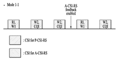
- the UE reports feedback content (eg, RI, W1, W2, and CQI) for each time point to the base station through the PUCCH.
- the first feedback time point after the A-CSI-RS enable / disable time point is transmitted from the information having the highest rank (eg, RI).
- an offset of the highest rank CSI may be set based on a corresponding enable signaling time point, and an offset of the remaining CSI may be given as a relative offset from the offset of the highest rank CSI.
- the container through which the CSI is transmitted uses the CSI feedback of the existing P-CSI-RS as it is. Therefore, the first CSI container after the A-CSI-RS enable time point is used as a higher rank CSI, that is, RI transmission, and the interval from the A-CSI-RS enable time point to the corresponding CSI container indicates that RI. May be determined as an offset for the
- the periodic CSI feedback offset for the P-CSI-RS may be given to the corresponding time even at the A-CSI-RS disable time. That is, the first feedback time point after the A-CSI-RS is disabled is transmitted from the CSI (eg, RI) having the highest rank. In this case, offset related information may not be given to the highest priority CSI (eg, RI) that is a reference during periodic CSI feedback setting for the A-CSI-RS and / or the P-CSI-RS. However, a relative reporting offset from the corresponding reference CSI type (eg, RI) may be given.
- the CSI-RS feedback enable / disable time may be limited to n-k.
- K may be the time required for the measurement of the CSI-RS and the calculation of the highest rank CSI, for example, RI.
- the application time of the signaling may be limited to a time n at which the CSI having the highest rank is performed, without limitation of the transmission / reception timing of the A-CSI-RS feedback enable / disable signaling.
- the transmission of the A-CSI-RS may be made at or before the time point n-k.
- the A-CSI-RS feedback enable / disable time point mentioned above may be explicitly indicated to the UE through L1 or L2 signaling.
- the time point designated through each signaling is offset of the periodic reporting scheme as described above. Can be determined.
- the A-CSI-RS feedback enable / disable time it may be pre-specified from a time point at which L1 / L2 signaling is received to a time point after a constant offset X.
- X 0 may be defined to set an offset of a CSI report to a reception point of L1 signaling, or MAC CE (control element) for L2 signaling.
- the MAC CE is applied from the reception time of the PDSCH including, for example, when the reception time of the PDSCH including the MAC CE is referred to as subframe n, this means that the offset of the CSI report is set to subframe n + 8.
- offsets of the corresponding CSI report types may be determined based on an enable / disable signaling time point. For example, if the RI, PMI, CQI is reported to the base station in a non-periodic CSI reporting method, the offset for the RI, 0 for the PMI may be set to 1, the offset for the CQI is 2, etc., in this case When n is 0 n, the offset of the RI report is set to n 0 , and the offsets of PMI and CQI are defined as n 0 +1 and n 0 +2, respectively.
- a unit of X may vary according to transmission numerology of UL resources and CSI reporting.
- an aperiodic CSI-interference measurement (hereinafter, A-CSI-IM) (resource) can be set for interference measurement.
- A-CSI-IM aperiodic CSI-interference measurement
- This configuration is similar to the above A-CSI-RS, but the UE regards the measurement result of the corresponding RS as interference in the CSI calculation.
- A-CSI-IM is an illustration of an A-CSI-IM. If A-CSI-IM is used as above, this A-CSI-IM is the same as X-CSI-RS (P-CSI-RS or A-CSI-RS) that will act as the desired signal. Transmitted, the terminal reports the CSI using the corresponding A-CSI-IM as interference.
- A-CSI-IM may be utilized in a multi-user (MU) case or coordinated multiple transmission / reception points (CoMP).
- MU multi-user
- CoMP coordinated multiple transmission / reception points
- the base station applies the beam used for the terminal 2 to the A-CSI-IM and transmits it as the A-CSI-IM of the terminal 1, the terminal is a corresponding A-CSI-
- the CSI applying the IM can be calculated and reported to the base station.
- the UE may calculate the CSI by considering the A-CSI-IM as interference, as the P-CSI-RS is a required signal.
- interference with the base station 1 and the base station 2 instead of the terminal 1 and 2 may be emulated (emulation) to the corresponding A-CSI-IM and transmitted.
- A-CSI-IM for different interference hypotheses may be transmitted at each A-CSI-IM time point. For example, if the A-CSI-IM is transmitted at 5 ms intervals and transmitted for a total of 20 ms, the emulated interference is transmitted as the A-CSI-IM, but for each transmission opportunity, the UE 2, 3, 4, and 5 are transmitted. Emulated interference can be transmitted.
- each A-CSI-IM has a corresponding CSI feedback instance is defined, and the terminal is a CSI corresponding to each A-CSI-IM (eg, MU CSI including the assumption of the terminal 2, 3, 4, 5) You can report it.
- the A-CSI-IM configuration may be set as follows.
- the base station transmits an A-CSI-IM indication to the terminal, and the terminal may calculate and report the CSI using the corresponding A-CSI-IM.
- A-CSI-IM can be indicated as a separate signaling for A-CSI-IM.
- A-CSI-RS and A-CSI-IM can be used simultaneously as shown in figure 4 (c).
- the base station may inform the transmission of the A-CSI-IM in every subframe instead of on / off of the A-CSI-IM.
- each A-CSI-RS / A-CSI-IM has a corresponding CSI feedback instance defined, and the CSI corresponding to each A-CSI-RS / A-CSI-IM (eg A-CSI-RS CSI is SU CSI / A-CSI-IM CSI may report MU CSI).
- the A-CSI-RS indication may specify a corresponding A-CSI-IM resource (or / and a CSI process including the A-CSI-IM). This case can be used in the situation as shown in Fig. 8 (a) or (b). Or specify an A-CSI-RS / A-CSI-IM pair previously defined in the A-CSI-RS indication or set to higher-layer signaling, or both A-CSI-RS and A-CSI-IM are defined.
- a CSI process can be designated and used in the situation as shown in FIG.
- A-CSI-RS / A-CSI-IM general purpose resources may be configured. Other settings are transmitted in the same manner as the A-CSI-RS, but a configuration in which the corresponding resource is A-CSI-RS / A-CSI-IM may be added.
- the base station transmits an A-CSI-RS / A-CSI-IM indication to the terminal and provides signaling on whether to use the corresponding resource as the A-CSI-RS or the A-CSI-IM and A-CSI-RS feedback.
- Signaling eg, A-CSI-RS / A-CSI-IM indication in DCI
- This may be used in the case of (a) and (b) of FIG. 8, where the A-CSI-RS / IM may be changed every subframe.
- each A-CSI-RS / A-CSI-IM has a corresponding CSI feedback opportunity defined, and the CSI corresponding to each A-CSI-RS / A-CSI-IM (eg, A-CSI-RS CSI).
- a single user (SU) CSI / A-CSI-IM CSI may report a multi-user (MU) CSI.
- the base station provides a corresponding A-CSI-RS / A-CSI-IM to the UE through A-CSI-RS feedback signaling through higher-layer signaling such as MAC signaling. It informs whether it is A-CSI-RS or A-CSI-IM. This may be used in all cases of FIG. 8, and the UE may calculate and report MU CSI or CoMP CSI on the assumption that the corresponding property is maintained in the same A-CSI-RS (IM) transmission interval.
- IM A-CSI-RS
- SP-CSI reporting is defined in situations such as FD-MIMO and new radio access technology (NR) -MIMO.
- the SP-CSI report has the following characteristics.
- a time interval for performing periodic CSI reporting is set to the UE.
- the UE reports the CSI to the base station using a schedule-less UL resource (eg, PUCCH) in a given period.
- a schedule-less UL resource eg, PUCCH
- the A-CSI-RS feedback signaling mentioned in the text has the same characteristics as the case of enabling / disabling through separate signaling from the A-CSI-RS, the A-CSI-RS feedback mentioned in the present patent It is clear that can be considered the same as the SP-CSI report.
- the SP-CSI enable / disable time point that is, the offset of the SP-CSI may be set to the UE at n + k time points through L1 / L2 signaling.
- n may be set as follows.
- the UE may be informed at which timing (n + k) an enable / disable (ie, a feedback offset) for CSI reporting is set. 9 illustrates this.
- a transmission time of a CSI-RS designated for CSI reporting may be set to n.
- a corresponding CSI-RS transmission time point may be set to time point n.
- the first CSI-RS transmission time point after the reception time of the DCI may be set to a time point n.
- the UE may be informed at which timing (n + k) an enable / disable (ie, a feedback offset) for CSI reporting is set.
- the UE may inform the UE at which timing (n + k) an enable / disable (ie, feedback offset) for CSI reporting is set based on the reception time n of the ACK / NACK for the PDSCH including the corresponding MAC CE.
- a transmission time of a CSI-RS designated for CSI reporting may be set to n.
- a corresponding CSI-RS transmission time point may be set to time point n.
- the first CSI-RS transmission time point after the reception time of the PDSCH including the corresponding MAC CE may be set to time point n.
- enable / disable signaling indicates which configuration according to the application timing of the above configuration. Can be.
- the terminal may assume that the CSI report configuration received from the base station is applied from the same timing.
- the UE may check the SP for the previous CSI reporting configuration before the above-described timing (that is, t ⁇ n (+ p) + k).
- the CSI feedback timing k may be specified in the following manner.
- Fixed timing k can be predefined.
- the CSI feedback timing may also be instructed to the UE only by the transmission / measurement timing indication of the CSI-RS.
- k When RS timing is defined as n, k may be designated as 4 ms or a corresponding timing (for example, 4 subframes).
- Fixed timing k may be included in the CSI process, stage setup, or RS setup.
- the CSI feedback timing may also be instructed to the UE only by the transmission / measurement timing indication of the CSI-RS.
- the range of k can be predetermined. Through the SP-CSI enable / disable signaling, a k value within a corresponding range may be assigned to the UE as L1 / L2 signaling.
- a range of k may be included in the CSI process, stage setup, or RS setup.
- a k value within a corresponding range may be assigned to the UE as L1 / L2 signaling.
- Disable signaling may be sent from the base station with signaling similar to the enable signaling. This, in contrast to the enable signaling, informs the terminal of the end of the SP-CSI report.
- the base station can transmit the corresponding signaling / status to the terminal so that the SP CSI is no longer reported from the terminal.
- an enable / disable state consisting of a bit field of DCI should be used to transmit the corresponding signaling to the UE.
- the corresponding SP CSI report can be disabled at a specified timing. For example, when a total of four CSI settings are configured through L2 / L3 signaling and indicate one of them through a 2-bit field of DCI to transmit enable signaling to the terminal, if the base station is in state "01", When the base station transmits the same "01 enable” signaling in a state where the "CSI report configuration 1" is enabled through the UE, the terminal interprets the signaling as "disable” and no longer performs the corresponding SP CSI report. .
- a specific attribute is set to a specified value during the SP-CSI configuration, for example, when a "0" resource for CSI is reset and / or a "0" period for CSI reporting, the UE does not report the corresponding SP-CSI. Can be considered.
- This scheme may be limited to L2 signaling in consideration of signaling overhead.
- a time interval for performing CSI reporting may be determined in advance.
- this scheme since the signaling overhead is expected to be larger than the above “explicit” disable “signaling” and “toggle” schemes, this scheme may be limited to L2 signaling.
- the existing operating SP-CSI reporting can be stopped.
- eMBB extreme or enhanced mobile broadband
- URLLC Ultra-Reliable and Low Latency Communication
- the above methods are regarded as only temporary interruption, and when the eMBB service is used again, existing SP-CSI reporting can be resumed with the same configuration (eg, period, offset, etc.). In this case, when the probability of resuming the SP-CSI reporting is high (eg, short time transmission of URLLC data), the SP-CSI enabling signaling may be reduced.
- the timing indication may be included in the disable signaling to inform the UE of the time when the corresponding signaling is valid, that is, when the reporting of the SP-CSI is stopped. It has a structure of n + k (+ v) similar to the timing indication included in the enable signaling above (k is not included), and ⁇ n and v have a similar meaning to the above enable signaling.
- the value k is the point at which the UE actually stops reporting the SP-CSI.
- This patent proposes a technique for periodic CSI reporting when using A-CSI-RS, but the same can be applied to aperiodic CSI reporting using A-CSI-RS.
- the aforementioned CSI may be included for periodic CSI.
- A-CSI-IM for aperiodic CSI reporting may be used in the same manner and together with A-CSI-RS transmitted in one-shot.
- in the actual application of the above technology can be applied alone or in combination of the above technology.
- FIG. 12 relates to a channel state reporting method based on aperiodic channel state information-reference signal (CSI-RS) in a wireless communication system.
- CSI-RS channel state information-reference signal
- the terminal may receive the aperiodic CSI-RS based channel state report indication (S1210).
- the terminal may transmit the CSI derived from the aperiodic CSI-RS according to the channel state report indication (S1220).
- the aperiodic CSI-RS is received periodically for a predetermined time interval, and the CSI transmitted at the first valid CSI reporting time point after the channel status report indication is received includes information of the type having the highest priority.
- the transmission offset of the type of information having the highest priority may be determined based on when the channel state report indication is received.
- the channel state report indication may be set to be received at a predetermined time point.
- the transmission offset of the type of information having the remaining priority among the derived CSI may be relatively determined from the transmission offset of the type of information having the highest priority.
- the derived CSI may be transmitted through an uplink control channel during a predetermined time interval.
- the time point at which the received channel status report indication is applied may be preset or explicitly set through other signaling.
- the embodiment related to FIG. 12 may alternatively or additionally include at least some of the above-described embodiment (s).
- FIG. 13 is a block diagram illustrating components of a transmitter 10 and a receiver 20 that perform embodiments of the present invention.
- the transmitter 10 and the receiver 20 are associated with transmitters / receivers 13 and 23 capable of transmitting or receiving radio signals carrying information and / or data, signals, messages, etc.
- Memory 12, 22 for storing a variety of information, the transmitter / receiver 13, 23 and the memory 12, 22 and the like is operatively connected to control the components to control the components described above
- the memories 12 and 22 may store a program for processing and controlling the processors 11 and 21, and may temporarily store input / output information.
- the memories 12 and 22 may be utilized as buffers.
- the processors 11 and 21 typically control the overall operation of the various modules in the transmitter or receiver. In particular, the processors 11 and 21 may perform various control functions for carrying out the present invention.
- the processors 11 and 21 may also be called controllers, microcontrollers, microprocessors, microcomputers, or the like.
- the processors 11 and 21 may be implemented by hardware or firmware, software, or a combination thereof.
- firmware or software When implementing the present invention using hardware, application specific integrated circuits (ASICs) or digital signal processors (DSPs), digital signal processing devices (DSPDs), programmable logic devices (PLDs), FPGAs ( field programmable gate arrays) may be provided in the processors 11 and 21.
- ASICs application specific integrated circuits
- DSPs digital signal processors
- DSPDs digital signal processing devices
- PLDs programmable logic devices
- FPGAs field programmable gate arrays
- firmware or software may be configured to include a module, a procedure, or a function for performing the functions or operations of the present invention, and configured to perform the present invention.
- the firmware or software may be provided in the processors 11 and 21 or stored in the memory 12 and 22 to be driven by the processors 11 and 21.
- the processor 11 of the transmission apparatus 10 is predetermined from the processor 11 or a scheduler connected to the processor 11 and has a predetermined encoding and modulation on a signal and / or data to be transmitted to the outside. After performing the transmission to the transmitter / receiver (13). For example, the processor 11 converts the data sequence to be transmitted into K layers through demultiplexing, channel encoding, scrambling, and modulation.
- the coded data string is also called a codeword and is equivalent to a transport block, which is a data block provided by the MAC layer.
- One transport block (TB) is encoded into one codeword, and each codeword is transmitted to a receiving device in the form of one or more layers.
- the transmitter / receiver 13 may include an oscillator for frequency upconversion.
- the transmitter / receiver 13 may include Nt transmit antennas, where Nt is a positive integer greater than or equal to one.
- the signal processing of the receiver 20 is the reverse of the signal processing of the transmitter 10.
- the transmitter / receiver 23 of the receiver 20 receives a radio signal transmitted by the transmitter 10.
- the transmitter / receiver 23 may include Nr receive antennas, and the transmitter / receiver 23 frequency down-converts each of the signals received through the receive antennas to restore baseband signals. do.
- Transmitter / receiver 23 may include an oscillator for frequency downconversion.
- the processor 21 may decode and demodulate a radio signal received through a reception antenna to restore data originally transmitted by the transmission apparatus 10.
- the transmitter / receiver 13, 23 is equipped with one or more antennas.
- the antenna transmits a signal processed by the transmitter / receiver 13, 23 to the outside or receives a radio signal from the outside under the control of the processors 11 and 21, thereby transmitting / receiving the transmitter / receiver. It performs the function of forwarding to (13, 23).
- Antennas are also called antenna ports.
- Each antenna may correspond to one physical antenna or may be configured by a combination of more than one physical antenna elements.
- the signal transmitted from each antenna can no longer be decomposed by the receiver 20.
- a reference signal (RS) transmitted in correspondence with the corresponding antenna defines the antenna as viewed from the perspective of the receiver 20, and whether the channel is a single radio channel from one physical antenna or includes the antenna.
- RS reference signal
- the receiver 20 enables channel estimation for the antenna. That is, the antenna is defined such that a channel carrying a symbol on the antenna can be derived from the channel through which another symbol on the same antenna is delivered.
- MIMO multi-input multi-output
- the terminal or the UE operates as the transmitter 10 in the uplink and the receiver 20 in the downlink.
- the base station or eNB operates as the receiving device 20 in the uplink, and operates as the transmitting device 10 in the downlink.
- the transmitter and / or the receiver may perform at least one or a combination of two or more of the embodiments of the present invention described above.
- the present invention can be used in a wireless communication device such as a terminal, a relay, a base station, and the like.
Landscapes
- Engineering & Computer Science (AREA)
- Signal Processing (AREA)
- Computer Networks & Wireless Communication (AREA)
- Quality & Reliability (AREA)
- Physics & Mathematics (AREA)
- Mathematical Physics (AREA)
- Mobile Radio Communication Systems (AREA)
Priority Applications (3)
| Application Number | Priority Date | Filing Date | Title |
|---|---|---|---|
| US16/312,295 US20190123801A1 (en) | 2016-06-23 | 2017-06-23 | Method for reporting channel state in wireless communication system and device therefor |
| EP17815742.6A EP3471311B1 (de) | 2016-06-23 | 2017-06-23 | Verfahren zur meldung des kanalstatus in einem drahtloskommunikationssystem und vorrichtung dafür |
| KR1020187036751A KR102208125B1 (ko) | 2016-06-23 | 2017-06-23 | 무선 통신 시스템에서 채널 상태 보고를 위한 방법 및 이를 위한 장치 |
Applications Claiming Priority (4)
| Application Number | Priority Date | Filing Date | Title |
|---|---|---|---|
| US201662354113P | 2016-06-23 | 2016-06-23 | |
| US62/354,113 | 2016-06-23 | ||
| US201662437687P | 2016-12-22 | 2016-12-22 | |
| US62/437,687 | 2016-12-22 |
Publications (1)
| Publication Number | Publication Date |
|---|---|
| WO2017222329A1 true WO2017222329A1 (ko) | 2017-12-28 |
Family
ID=60783977
Family Applications (1)
| Application Number | Title | Priority Date | Filing Date |
|---|---|---|---|
| PCT/KR2017/006622 WO2017222329A1 (ko) | 2016-06-23 | 2017-06-23 | 무선 통신 시스템에서 채널 상태 보고를 위한 방법 및 이를 위한 장치 |
Country Status (4)
| Country | Link |
|---|---|
| US (1) | US20190123801A1 (de) |
| EP (1) | EP3471311B1 (de) |
| KR (1) | KR102208125B1 (de) |
| WO (1) | WO2017222329A1 (de) |
Cited By (11)
| Publication number | Priority date | Publication date | Assignee | Title |
|---|---|---|---|---|
| CN109644365A (zh) * | 2018-03-02 | 2019-04-16 | Oppo广东移动通信有限公司 | 无线通信方法和设备 |
| WO2019242501A1 (en) | 2018-06-20 | 2019-12-26 | FG Innovation Company Limited | Method and apparatus for handling embb and urllc simultaneous transmissions |
| WO2020091498A1 (ko) * | 2018-11-02 | 2020-05-07 | 엘지전자 주식회사 | 무선 통신 시스템에서 단말 및 기지국의 동작 방법 및 이를 지원하는 장치 |
| KR20200070301A (ko) * | 2017-10-20 | 2020-06-17 | 가부시키가이샤 엔티티 도코모 | 유저단말 및 무선 통신 방법 |
| CN111684744A (zh) * | 2018-01-04 | 2020-09-18 | 欧芬诺有限责任公司 | 半持久信道状态信息报告 |
| CN111837352A (zh) * | 2018-01-12 | 2020-10-27 | 瑞典爱立信有限公司 | 半持续csi报告的激活和去激活 |
| CN111955023A (zh) * | 2018-02-15 | 2020-11-17 | 株式会社Ntt都科摩 | 用户终端以及无线通信方法 |
| EP3739983A4 (de) * | 2018-02-23 | 2020-12-09 | Guangdong Oppo Mobile Telecommunications Corp., Ltd. | Verfahren zum senden von downlink-steuerungsinformationen, endgerät und netzwerkvorrichtung |
| CN112166637A (zh) * | 2018-05-17 | 2021-01-01 | 汉阳大学校产学协力团 | 信道状态信息传输方法及其装置 |
| US11888563B2 (en) | 2018-08-10 | 2024-01-30 | Huawei Technologies Co., Ltd. | Channel state information reporting method and apparatus |
| US12068824B2 (en) | 2018-05-17 | 2024-08-20 | Hyundai Motor Company | Method and apparatus for transmitting channel state information |
Families Citing this family (12)
| Publication number | Priority date | Publication date | Assignee | Title |
|---|---|---|---|---|
| JP6951416B2 (ja) * | 2016-08-05 | 2021-10-20 | エルジー エレクトロニクス インコーポレイティドLg Electronics Inc. | 無線通信システムにおけるチャネル態報告のための方法及びその装置 |
| CN108809606A (zh) * | 2016-11-04 | 2018-11-13 | 华为技术有限公司 | 信道状态信息反馈的方法与装置 |
| JP7112421B2 (ja) | 2017-03-24 | 2022-08-03 | テレフオンアクチーボラゲット エルエム エリクソン(パブル) | Puschを介したセミパーシステントcsiフィードバック |
| WO2018199703A1 (ko) * | 2017-04-28 | 2018-11-01 | 엘지전자 주식회사 | 무선 통신 시스템에서 채널 상태 정보를 보고하기 위한 방법 및 이를 위한 장치 |
| WO2018227538A1 (en) * | 2017-06-16 | 2018-12-20 | Qualcomm Incorporated | Reporting aperiodic csi via pucch |
| US11128359B2 (en) | 2018-01-04 | 2021-09-21 | Comcast Cable Communications, Llc | Methods and systems for information reporting |
| PL3738262T3 (pl) | 2018-01-12 | 2022-05-02 | Telefonaktiebolaget Lm Ericsson (Publ) | Włączanie i wyłączanie półtrwałego zgłaszania CSI |
| US11006445B2 (en) * | 2018-02-08 | 2021-05-11 | Ofinno, Llc | Confirmation mechanism for CSI report activation and deactivation |
| US11483044B2 (en) * | 2019-09-20 | 2022-10-25 | Qualcomm Incorporated | Channel state information reporting prioritization |
| EP4226553A1 (de) * | 2020-10-09 | 2023-08-16 | Telefonaktiebolaget LM Ericsson (publ) | Systeme und verfahren zur timing-bestimmung für aperiodisches csi auf pucch |
| US11917669B2 (en) | 2020-11-06 | 2024-02-27 | Electronics And Telecommunications Research Institute | Method and apparatus for transmitting and receiving signal for cooperative transmission in communication system |
| JP2022138966A (ja) * | 2021-03-11 | 2022-09-26 | パナソニックホールディングス株式会社 | 基地局、端末、及び、通信方法 |
Citations (2)
| Publication number | Priority date | Publication date | Assignee | Title |
|---|---|---|---|---|
| KR20150035555A (ko) * | 2012-07-02 | 2015-04-06 | 엘지전자 주식회사 | 무선 통신 시스템에서 채널상태정보 보고 방법 및 장치 |
| WO2015060681A1 (ko) * | 2013-10-24 | 2015-04-30 | 엘지전자 주식회사 | 무선 통신 시스템에서 채널 상태 정보를 보고하는 방법 및 이를 위한 장치 |
Family Cites Families (8)
| Publication number | Priority date | Publication date | Assignee | Title |
|---|---|---|---|---|
| US9001747B2 (en) * | 2008-03-26 | 2015-04-07 | Nokia Corporation | Reporting channel state information |
| EP2289187B1 (de) * | 2008-06-04 | 2016-12-14 | Wireless Future Technologies Inc. | Kanalqualitätssignalisierung für persistente/semipersistente funkressourcenzuweisungen |
| CN102684835B (zh) * | 2012-05-10 | 2015-05-20 | 电信科学技术研究院 | 多点信道状态信息的上报方法和设备 |
| US9980167B2 (en) * | 2012-05-30 | 2018-05-22 | Telefonaktiebolaget Lm Ericsson (Publ) | Methods and network nodes for managing transmission of at least one channel quality report |
| WO2015012653A1 (en) * | 2013-07-25 | 2015-01-29 | Lg Electronics Inc. | Method of reporting channel state information and apparatus thereof |
| US10033507B2 (en) * | 2014-07-28 | 2018-07-24 | Lg Electronics Inc. | Method for performing channel estimation, and apparatus therefor |
| US20160149679A1 (en) * | 2014-10-10 | 2016-05-26 | Telefonaktiebolaget L M Ericsson (Publ) | Method for dynamic csi feedback |
| US10404332B2 (en) * | 2016-01-28 | 2019-09-03 | Qualcomm Incorporated | Downlink common burst channelization |
-
2017
- 2017-06-23 WO PCT/KR2017/006622 patent/WO2017222329A1/ko unknown
- 2017-06-23 EP EP17815742.6A patent/EP3471311B1/de active Active
- 2017-06-23 US US16/312,295 patent/US20190123801A1/en not_active Abandoned
- 2017-06-23 KR KR1020187036751A patent/KR102208125B1/ko active IP Right Grant
Patent Citations (2)
| Publication number | Priority date | Publication date | Assignee | Title |
|---|---|---|---|---|
| KR20150035555A (ko) * | 2012-07-02 | 2015-04-06 | 엘지전자 주식회사 | 무선 통신 시스템에서 채널상태정보 보고 방법 및 장치 |
| WO2015060681A1 (ko) * | 2013-10-24 | 2015-04-30 | 엘지전자 주식회사 | 무선 통신 시스템에서 채널 상태 정보를 보고하는 방법 및 이를 위한 장치 |
Non-Patent Citations (4)
| Title |
|---|
| LG ELECTRONICS: "Discussion on CSI Reporting Enhancements for Hybrid CSI-RS", R1-164526, 3GPP TSG RAN WG1 MEETING #85, 14 May 2016 (2016-05-14), XP051096406 * |
| SAMSUNG: "On Aperiodic CSI-RS Design", R1-164773, 3GPP TSG RAN WG1 #85, 13 May 2016 (2016-05-13), XP051090138 * |
| See also references of EP3471311A4 * |
| XINWEI: "Discussion on CSI Reporting for Hybrid CSI-RS", R1-164895, 3GPP TSG RAN WG1 MEETING #85, 13 May 2016 (2016-05-13), XP051090230 * |
Cited By (28)
| Publication number | Priority date | Publication date | Assignee | Title |
|---|---|---|---|---|
| KR102458260B1 (ko) | 2017-10-20 | 2022-10-25 | 가부시키가이샤 엔티티 도코모 | 유저단말 및 무선 통신 방법 |
| KR20200070301A (ko) * | 2017-10-20 | 2020-06-17 | 가부시키가이샤 엔티티 도코모 | 유저단말 및 무선 통신 방법 |
| CN111684744B (zh) * | 2018-01-04 | 2022-04-29 | 三星电子株式会社 | 半持久信道状态信息报告的方法、装置和计算机可读介质 |
| US11122642B2 (en) | 2018-01-04 | 2021-09-14 | Samsung Electronics Co., Ltd. | Beam failure recovery procedure |
| CN111684744A (zh) * | 2018-01-04 | 2020-09-18 | 欧芬诺有限责任公司 | 半持久信道状态信息报告 |
| US10951355B2 (en) | 2018-01-04 | 2021-03-16 | Samsung Electronics Co., Ltd. | Preamble transmission counter for a beam failure recover of a wireless device |
| CN111837352A (zh) * | 2018-01-12 | 2020-10-27 | 瑞典爱立信有限公司 | 半持续csi报告的激活和去激活 |
| CN111955023A (zh) * | 2018-02-15 | 2020-11-17 | 株式会社Ntt都科摩 | 用户终端以及无线通信方法 |
| EP3739983A4 (de) * | 2018-02-23 | 2020-12-09 | Guangdong Oppo Mobile Telecommunications Corp., Ltd. | Verfahren zum senden von downlink-steuerungsinformationen, endgerät und netzwerkvorrichtung |
| US11516836B2 (en) | 2018-02-23 | 2022-11-29 | Guangdong Oppo Mobile Telecommunications Corp., Ltd. | Downlink control information transmission method, terminal device and network device |
| CN112202539A (zh) * | 2018-02-23 | 2021-01-08 | Oppo广东移动通信有限公司 | 下行控制信息传输方法、终端设备和网络设备 |
| KR20200118184A (ko) * | 2018-03-02 | 2020-10-14 | 광동 오포 모바일 텔레커뮤니케이션즈 코포레이션 리미티드 | 무선 통신 방법과 장치 |
| WO2019165638A1 (zh) * | 2018-03-02 | 2019-09-06 | Oppo广东移动通信有限公司 | 无线通信方法和设备 |
| EP3737144A4 (de) * | 2018-03-02 | 2020-11-25 | Guangdong Oppo Mobile Telecommunications Corp., Ltd. | Drahtloskommunikationsverfahren und -vorrichtung |
| CN109644365A (zh) * | 2018-03-02 | 2019-04-16 | Oppo广东移动通信有限公司 | 无线通信方法和设备 |
| CN109644365B (zh) * | 2018-03-02 | 2020-08-04 | Oppo广东移动通信有限公司 | 无线通信方法和设备 |
| AU2018411307B2 (en) * | 2018-03-02 | 2021-09-30 | Guangdong Oppo Mobile Telecommunications Corp., Ltd. | Wireless communication method and device |
| KR102392463B1 (ko) | 2018-03-02 | 2022-04-28 | 광동 오포 모바일 텔레커뮤니케이션즈 코포레이션 리미티드 | 무선 통신 방법과 장치 |
| US11539414B2 (en) | 2018-03-02 | 2022-12-27 | Guangdong Oppo Mobile Telecommunications Corp., Ltd. | Wireless communication method and device |
| US12068824B2 (en) | 2018-05-17 | 2024-08-20 | Hyundai Motor Company | Method and apparatus for transmitting channel state information |
| CN112166637B (zh) * | 2018-05-17 | 2024-04-02 | 现代自动车株式会社 | 信道状态信息传输方法及其装置 |
| CN112166637A (zh) * | 2018-05-17 | 2021-01-01 | 汉阳大学校产学协力团 | 信道状态信息传输方法及其装置 |
| CN112335284B (zh) * | 2018-06-20 | 2023-10-20 | 鸿颖创新有限公司 | 用于处理eMBB和URLLC同时传输的方法和装置 |
| WO2019242501A1 (en) | 2018-06-20 | 2019-12-26 | FG Innovation Company Limited | Method and apparatus for handling embb and urllc simultaneous transmissions |
| EP3811665A4 (de) * | 2018-06-20 | 2022-04-13 | FG Innovation Company Limited | Verfahren und vorrichtung zur handhabung von gleichzeitigen embb- und urllc-übertragungen |
| CN112335284A (zh) * | 2018-06-20 | 2021-02-05 | 鸿颖创新有限公司 | 用于处理eMBB和URLLC同时传输的方法和装置 |
| US11888563B2 (en) | 2018-08-10 | 2024-01-30 | Huawei Technologies Co., Ltd. | Channel state information reporting method and apparatus |
| WO2020091498A1 (ko) * | 2018-11-02 | 2020-05-07 | 엘지전자 주식회사 | 무선 통신 시스템에서 단말 및 기지국의 동작 방법 및 이를 지원하는 장치 |
Also Published As
| Publication number | Publication date |
|---|---|
| KR102208125B1 (ko) | 2021-01-27 |
| EP3471311A1 (de) | 2019-04-17 |
| EP3471311A4 (de) | 2020-02-26 |
| US20190123801A1 (en) | 2019-04-25 |
| KR20190008929A (ko) | 2019-01-25 |
| EP3471311B1 (de) | 2022-10-26 |
Similar Documents
| Publication | Publication Date | Title |
|---|---|---|
| WO2017222329A1 (ko) | 무선 통신 시스템에서 채널 상태 보고를 위한 방법 및 이를 위한 장치 | |
| WO2018026230A1 (ko) | 무선 통신 시스템에서 채널 상태 보고를 위한 방법 및 이를 위한 장치 | |
| WO2016204546A1 (ko) | 비주기적 채널 상태 정보-참조 신호를 이용한 채널 상태 보고를 위한 방법 및 이를 위한 장치 | |
| WO2018056784A1 (ko) | 무선 통신 시스템에서 간섭 측정을 위한 방법 및 이를 위한 장치 | |
| WO2018030804A1 (ko) | 무선 통신 시스템에서 채널 상태 보고를 위한 방법 및 이를 위한 장치 | |
| WO2016126063A1 (ko) | 무선 통신 시스템에서 채널 상태 보고 방법 및 이를 위한 장치 | |
| WO2018226039A2 (ko) | 무선 통신 시스템에서 하향링크 신호를 수신 또는 전송하기 위한 방법 및 이를 위한 장치 | |
| WO2019160361A1 (ko) | 무선 통신 시스템에서 신호를 송수신하는 방법 및 장치 | |
| WO2019017753A1 (ko) | 무선 통신 시스템에서 채널 상태 보고를 위한 방법 및 이를 위한 장치 | |
| WO2017171307A1 (ko) | 비주기적 채널 상태 정보-참조 신호를 이용한 채널 상태 보고를 위한 방법 및 이를 위한 장치 | |
| WO2016163819A1 (ko) | 채널 상태 보고를 위한 방법 및 이를 위한 장치 | |
| WO2016144050A1 (ko) | 무선 통신 시스템에서 신호를 전송하기 위한 방법 및 이를 위한 장치 | |
| WO2016072712A2 (ko) | 채널과 관련된 피드백을 위한 방법 및 이를 위한 장치 | |
| WO2016093600A1 (ko) | 상향링크 제어 정보를 전송하기 위한 방법 및 이를 위한 장치 | |
| WO2018164452A1 (ko) | 무선 통신 시스템에서 하향링크 신호를 수신 또는 전송하기 위한 방법 및 이를 위한 장치 | |
| WO2017105135A2 (ko) | 무선 통신 시스템에서 상향링크 참조 신호 전송 또는 수신 방법 및 이를 위한 장치 | |
| WO2016122197A1 (ko) | 상향링크 신호를 전송하기 위한 방법 및 이를 위한 장치 | |
| WO2018208087A1 (ko) | 무선 통신 시스템에서 상향링크 신호를 전송하기 위한 방법 및 이를 위한 장치 | |
| WO2018128340A1 (ko) | 무선 통신 시스템에서 채널 상태 보고를 위한 방법 및 이를 위한 장치 | |
| WO2018030714A1 (ko) | 무선 통신 시스템에서 채널 상태 보고를 위한 방법 및 이를 위한 장치 | |
| WO2017052193A1 (ko) | 비면허 대역에서 데이터를 송수신하는 방법 및 이를 위한 장치 | |
| WO2017171516A1 (ko) | 무선 통신 시스템에서 상향링크 제어 정보의 전송 또는 수신 방법 및 이를 위한 장치 | |
| WO2018236180A1 (ko) | 무선 통신 시스템에서 채널 상태 보고를 위한 방법 및 이를 위한 장치 | |
| WO2017034182A1 (ko) | 무선 통신 시스템에서 위치 결정을 위한 참조 신호 수신 또는 전송 방법 및 이를 위한 장치 | |
| WO2017039166A1 (ko) | 채널 상태 보고 방법 및 이를 위한 장치 |
Legal Events
| Date | Code | Title | Description |
|---|---|---|---|
| 121 | Ep: the epo has been informed by wipo that ep was designated in this application |
Ref document number: 17815742 Country of ref document: EP Kind code of ref document: A1 |
|
| ENP | Entry into the national phase |
Ref document number: 20187036751 Country of ref document: KR Kind code of ref document: A |
|
| NENP | Non-entry into the national phase |
Ref country code: DE |
|
| ENP | Entry into the national phase |
Ref document number: 2017815742 Country of ref document: EP Effective date: 20190108 |