WO2017221823A1 - Vibration damping device - Google Patents
Vibration damping device Download PDFInfo
- Publication number
- WO2017221823A1 WO2017221823A1 PCT/JP2017/022266 JP2017022266W WO2017221823A1 WO 2017221823 A1 WO2017221823 A1 WO 2017221823A1 JP 2017022266 W JP2017022266 W JP 2017022266W WO 2017221823 A1 WO2017221823 A1 WO 2017221823A1
- Authority
- WO
- WIPO (PCT)
- Prior art keywords
- liquid chamber
- flow path
- barrier
- pores
- liquid
- Prior art date
Links
Images

Classifications
-
- F—MECHANICAL ENGINEERING; LIGHTING; HEATING; WEAPONS; BLASTING
- F16—ENGINEERING ELEMENTS AND UNITS; GENERAL MEASURES FOR PRODUCING AND MAINTAINING EFFECTIVE FUNCTIONING OF MACHINES OR INSTALLATIONS; THERMAL INSULATION IN GENERAL
- F16F—SPRINGS; SHOCK-ABSORBERS; MEANS FOR DAMPING VIBRATION
- F16F13/00—Units comprising springs of the non-fluid type as well as vibration-dampers, shock-absorbers, or fluid springs
- F16F13/04—Units comprising springs of the non-fluid type as well as vibration-dampers, shock-absorbers, or fluid springs comprising both a plastics spring and a damper, e.g. a friction damper
- F16F13/06—Units comprising springs of the non-fluid type as well as vibration-dampers, shock-absorbers, or fluid springs comprising both a plastics spring and a damper, e.g. a friction damper the damper being a fluid damper, e.g. the plastics spring not forming a part of the wall of the fluid chamber of the damper
- F16F13/08—Units comprising springs of the non-fluid type as well as vibration-dampers, shock-absorbers, or fluid springs comprising both a plastics spring and a damper, e.g. a friction damper the damper being a fluid damper, e.g. the plastics spring not forming a part of the wall of the fluid chamber of the damper the plastics spring forming at least a part of the wall of the fluid chamber of the damper
- F16F13/10—Units comprising springs of the non-fluid type as well as vibration-dampers, shock-absorbers, or fluid springs comprising both a plastics spring and a damper, e.g. a friction damper the damper being a fluid damper, e.g. the plastics spring not forming a part of the wall of the fluid chamber of the damper the plastics spring forming at least a part of the wall of the fluid chamber of the damper the wall being at least in part formed by a flexible membrane or the like
- F16F13/105—Units comprising springs of the non-fluid type as well as vibration-dampers, shock-absorbers, or fluid springs comprising both a plastics spring and a damper, e.g. a friction damper the damper being a fluid damper, e.g. the plastics spring not forming a part of the wall of the fluid chamber of the damper the plastics spring forming at least a part of the wall of the fluid chamber of the damper the wall being at least in part formed by a flexible membrane or the like characterised by features of partitions between two working chambers
- F16F13/107—Passage design between working chambers
-
- F—MECHANICAL ENGINEERING; LIGHTING; HEATING; WEAPONS; BLASTING
- F16—ENGINEERING ELEMENTS AND UNITS; GENERAL MEASURES FOR PRODUCING AND MAINTAINING EFFECTIVE FUNCTIONING OF MACHINES OR INSTALLATIONS; THERMAL INSULATION IN GENERAL
- F16F—SPRINGS; SHOCK-ABSORBERS; MEANS FOR DAMPING VIBRATION
- F16F13/00—Units comprising springs of the non-fluid type as well as vibration-dampers, shock-absorbers, or fluid springs
- F16F13/04—Units comprising springs of the non-fluid type as well as vibration-dampers, shock-absorbers, or fluid springs comprising both a plastics spring and a damper, e.g. a friction damper
- F16F13/06—Units comprising springs of the non-fluid type as well as vibration-dampers, shock-absorbers, or fluid springs comprising both a plastics spring and a damper, e.g. a friction damper the damper being a fluid damper, e.g. the plastics spring not forming a part of the wall of the fluid chamber of the damper
- F16F13/08—Units comprising springs of the non-fluid type as well as vibration-dampers, shock-absorbers, or fluid springs comprising both a plastics spring and a damper, e.g. a friction damper the damper being a fluid damper, e.g. the plastics spring not forming a part of the wall of the fluid chamber of the damper the plastics spring forming at least a part of the wall of the fluid chamber of the damper
- F16F13/10—Units comprising springs of the non-fluid type as well as vibration-dampers, shock-absorbers, or fluid springs comprising both a plastics spring and a damper, e.g. a friction damper the damper being a fluid damper, e.g. the plastics spring not forming a part of the wall of the fluid chamber of the damper the plastics spring forming at least a part of the wall of the fluid chamber of the damper the wall being at least in part formed by a flexible membrane or the like
Definitions
- the present invention relates to a vibration isolator that is applied to, for example, automobiles and industrial machines and absorbs and attenuates vibrations of a vibration generating unit such as an engine.
- This application claims priority based on Japanese Patent Application No. 2016-124914 for which it applied to Japan on June 23, 2016, and uses the content here.
- this type of vibration isolator a cylindrical first attachment member connected to one of the vibration generating portion and the vibration receiving portion, a second attachment member connected to the other, and both of these attachment members
- a configuration including an elastic body that connects the two and a partition member that divides a liquid chamber in a first mounting member in which a liquid is sealed into a main liquid chamber and a sub liquid chamber.
- the partition member is formed with a restriction passage that communicates the main liquid chamber and the sub liquid chamber.
- this vibration isolator for example, a large load (vibration) is input from the unevenness of the road surface, etc., and the load is input in the reverse direction due to the rebound of the elastic body after the fluid pressure in the main fluid chamber suddenly increases.
- the main liquid chamber is suddenly depressurized. Then, cavitation in which a large number of bubbles are generated in the liquid due to this sudden negative pressure is generated, and abnormal noise may be generated due to cavitation collapse in which the generated bubbles collapse. Therefore, for example, by providing a valve body in the restriction passage as in the vibration isolator shown in Patent Document 1 below, the main liquid chamber can be negatively pressured even when large amplitude vibration is input. Suppressing configurations are known.
- the conventional vibration isolator has a problem that the structure is complicated by providing the valve body, and tuning of the valve body is required, which increases the manufacturing cost. Further, the provision of the valve body reduces the degree of freedom in design, and as a result, the vibration isolation characteristics may be reduced.
- the present invention has been made in view of the above circumstances, and an object thereof is to provide a vibration isolator capable of suppressing the occurrence of abnormal noise due to cavitation collapse without reducing the vibration isolation characteristics with a simple structure. To do.
- the vibration isolator of the present invention includes a cylindrical first mounting member connected to one of the vibration generating unit and the vibration receiving unit, a second mounting member connected to the other, and both the mounting members.
- An elastic body that is elastically coupled; and a partition member that partitions the liquid chamber in the first mounting member in which the liquid is sealed into a first liquid chamber and a second liquid chamber; and the partition member,
- a liquid-filled vibration isolator having a restriction passage communicating the first liquid chamber and the second liquid chamber, wherein the restriction passage is formed in a first barrier facing the first liquid chamber.
- the present invention it is possible to provide a vibration isolator capable of suppressing the generation of abnormal noise due to cavitation collapse without reducing the vibration isolation characteristics with a simple structure.
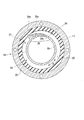
- FIG. 2 is an AA cross-sectional view of the partition member and the elastic body shown in FIG. It is sectional drawing of the partition member and elastic body which concern on 2nd Embodiment.
- the vibration isolator 10 is connected to a cylindrical first mounting member 11 connected to one of the vibration generating unit and the vibration receiving unit, and to the other of the vibration generating unit and the vibration receiving unit.
- a liquid-sealed vibration isolator including a partition member 16 partitioned into a chamber 15.
- the central axis of the first mounting member 11 is referred to as an axis O
- the direction along the axis O is referred to as an axial direction.
- the second mounting member 12 side along the axial direction is referred to as the upper side
- the partition member 16 side is referred to as the lower side.
- a direction orthogonal to the axis O is referred to as a “radial direction”
- a direction around the axis O is referred to as a “circumferential direction”.
- the first mounting member 11, the second mounting member 12, and the elastic body 13 are each formed in a circular shape or an annular shape in a plan view, and are disposed coaxially with the axis O.
- the second mounting member 12 is connected to an engine as a vibration generating unit, and the first mounting member 11 is connected to a vehicle body as a vibration receiving unit. This suppresses transmission of engine vibration to the vehicle body.
- the second mounting member 12 is a columnar member extending in the axial direction, and has a lower end formed in a hemispherical shape, and has a flange 12a above the lower end of the hemispherical shape.
- a screw hole 12b extending downward from the upper end surface of the second mounting member 12 is formed in the upper portion, and a bolt (not shown) serving as a mounting tool on the engine side is screwed into the screw hole 12b. It has become so.
- the second mounting member 12 is disposed on the upper end opening side of the first mounting member 11 via the elastic body 13.
- the elastic body 13 is a rubber body that is vulcanized and bonded to the upper end opening of the first mounting member 11 and the lower end side outer peripheral surface of the second mounting member 12, respectively, and interposed between them.
- the upper end opening of the mounting member 11 is closed from above.
- the elastic body 13 is sufficiently in close contact with the second mounting member 12 by the upper end of the elastic body 13 coming into contact with the flange portion 12 a of the second mounting member 12, so that the elastic body 13 follows better due to the displacement of the second mounting member 12. It has become.
- a rubber film 17 is integrally formed at the lower end portion of the elastic body 13 to liquid-tightly cover the inner peripheral surface of the first mounting member 11 and a part of the lower end opening edge.
- an elastic body made of synthetic resin or the like can be used in addition to rubber.
- the first mounting member 11 is formed in a cylindrical shape having a flange 18 at a lower end portion, and is connected to a vehicle body or the like as a vibration receiving portion via the flange 18. A portion of the inside of the first attachment member 11 located below the elastic body 13 is a liquid chamber 19.
- a partition member 16 is provided in the lower end portion of the first mounting member 11, and a diaphragm 20 is further provided below the partition member 16.
- the diaphragm 20 is made of an elastic material such as rubber or soft resin, and is formed in a bottomed cylindrical shape.
- the upper end portion of the diaphragm 20 is sandwiched between the partition member 16 and the ring-shaped holder 21 positioned below the partition member 16 in the axial direction.
- an annular mounting groove 16 a is formed on the lower surface of the partition member 16, in which the upper end portion of the diaphragm 20 is liquid-tightly engaged.
- a lower flange portion 22 is formed on the outer periphery of the partition member 16, and the upper surface of the holder 21 is in contact with the lower surface of the lower flange portion 22.
- the lower flange portion 22 of the partition member 16 and the holder 21 are disposed in this order at the lower end opening edge of the first mounting member 11 in this order, and are fixed by screws 23.
- the diaphragm 20 is attached to the lower end opening of the first attachment member 11 via the partition member 16.
- the diaphragm 20 has a bottom that is deep at the outer peripheral side and shallow at the center.
- various conventionally known shapes can be adopted in addition to such a shape.
- the liquid chamber 19 is formed in the first attachment member 11 by attaching the diaphragm 20 to the first attachment member 11 via the partition member 16 in this way.
- the liquid chamber 19 is disposed in the first mounting member 11, that is, inside the first mounting member 11 in plan view, and is a sealed space that is liquid-tightly sealed by the elastic body 13 and the diaphragm 20. It has become.
- the liquid chamber 19 is filled (filled) with the liquid L.
- the liquid chamber 19 is partitioned into a main liquid chamber 14 and a sub liquid chamber 15 by a partition member 16.
- the main liquid chamber 14 is formed by using the lower surface 13a of the elastic body 13 as a part of the wall surface.
- the rubber film 17 and the partition member 16 that cover the elastic body 13 and the inner peripheral surface of the first mounting member 11 in a liquid-tight manner.
- the inner volume changes due to the deformation of the elastic body 13.
- the auxiliary liquid chamber 15 is a space surrounded by the diaphragm 20 and the partition member 16, and the internal volume changes due to the deformation of the diaphragm 20.
- the vibration isolator 10 having such a configuration is a compression-type device that is mounted and used so that the main liquid chamber 14 is positioned on the upper side in the vertical direction and the auxiliary liquid chamber 15 is positioned on the lower side in the vertical direction. .
- a holding groove 16b that holds the lower end portion of the rubber film 17 in a liquid-tight manner is formed in a portion of the upper surface of the partition member 16 that is continuous with the inner peripheral edge of the lower flange portion 22.
- an annular upper flange portion 16 c whose outer peripheral surface is in liquid-tight contact with the inner peripheral surface of the rubber film 17 is formed at the upper end portion of the partition member 16. The space between the rubber film 17 and the partition member 16 is liquid-tightly closed by the holding groove 16b and the upper flange portion 16c.
- the partition member 16 is provided with a restriction passage 24 that allows the main liquid chamber 14 and the sub liquid chamber 15 to communicate with each other.
- the restriction passage 24 includes a main body flow path 25 disposed in the partition member 16, a first communication portion 26 that communicates the main body flow path 25 and the main liquid chamber 14, and a main body. And a second communication portion 27 that communicates the flow path 25 and the auxiliary liquid chamber 15.
- the main body flow path 25 extends along the circumferential direction in the partition member 16, and the flow path direction R and the circumferential direction of the main body flow path 25 are in the same direction.
- the main body flow path 25 is formed in an arc shape arranged coaxially with the axial center O, and extends over the entire circumference along the circumferential direction. Both end portions along the circumferential direction of the main body flow path 25 are separated from each other by partition walls 28a extending in the radial direction and the axial direction.
- the main body flow path 25 is defined by the first barrier 28 facing the main liquid chamber 14, the second barrier 29 facing the sub liquid chamber 15, the upper flange portion 16c, the rubber film 17, and the partition wall 28a. Has been. Note that the first barrier 28 and the second barrier 29 may not define the main body flow path 25.
- the first barrier 28 is formed in a cylindrical shape extending downward from the inner peripheral edge of the upper flange portion 16c. As shown in FIG. 2, the portion of the outer peripheral surface of the first barrier 28 where the first communication portion 26 is disposed gradually increases in the outer radial direction as the distance from the second communication portion 27 in the flow path direction R increases. Heading to For this reason, in the main body channel 25, the channel area at the connection portion 25 a with the first communication part 26 gradually decreases as the distance from the second communication part 27 in the channel direction R increases.
- the second barrier 29 is formed in a plate shape whose front and back surfaces face the axial direction. The upper surface of the second barrier 29 and the lower end of the first barrier 28 are connected to each other.
- the first barrier 28 is sandwiched between the main body flow path 25 and the main liquid chamber 14 in the radial direction, and is positioned between the main body flow path 25 and the main liquid chamber 14.
- the second barrier 29 is sandwiched between the main body flow path 25 and the secondary liquid chamber 15 in the axial direction, and is positioned between the main body flow path 25 and the secondary liquid chamber 15.
- the first communication portion 26 includes a plurality of pores 26 a that penetrate the first barrier 28 in the radial direction and are disposed along the flow path direction R.
- the plurality of pores 26 a are arranged in a portion of the first barrier 28 that forms one end portion along the circumferential direction of the main body flow path 25.
- the second communication portion 27 is an opening that penetrates the second barrier 29 in the axial direction.
- the second communication portion 27 is disposed in a portion of the second barrier 29 that forms the other end portion along the circumferential direction of the main body flow path 25.
- the plurality of pores 26a are all formed in a rectangular parallelepiped shape.
- the openings of the plurality of pores 26a toward the main liquid chamber 14 are all formed in a rectangular shape that is longer in the axial direction than in the circumferential direction when viewed from the inside in the radial direction.
- the channel cross-sectional areas of the plurality of pores 26a are the same over the entire length of the channel length of each pore 26a.
- the circumferential widths of the plurality of pores 26a are equal to each other.
- the plurality of pores 26a are arranged at equal intervals in the circumferential direction.
- the axial lengths of the plurality of pores 26a are smaller as they are spaced apart from the second communication portion 27 in the flow direction R.
- the projected area or the opening area of the minimum cross section is smaller as the plurality of pores 26a are positioned away from the second communication portion 27 in the flow path direction R.
- the ratio of the projected area or the opening area of the minimum cross section of the pore 26 a occupying per predetermined area on the inner peripheral surface facing the main liquid chamber 14 in the first barrier 28 is from the second communication portion 27.
- the plurality of pores 26a have a longer channel length as they are spaced from the second communicating portion 27 in the channel direction R. As described above, as the plurality of pores 26a are spaced apart from the second communication portion 27 in the flow direction R, the resistance when the liquid L flows through the pores 26a increases.
- the “projection area” is a narrow area passing through the center of the minimum cross section of the pore 26a to the surface of the first barrier 28 or the second barrier 29 located in the main liquid chamber 14 or the sub liquid chamber 15. The projected area in the direction in which the hole center line extends.
- the two attachment members 11 and 12 are relatively displaced while elastically deforming the elastic body 13 at the time of vibration input.
- the liquid pressure in the main liquid chamber 14 fluctuates, the liquid L in the main liquid chamber 14 flows into the sub liquid chamber 15 through the restriction passage 24, and the liquid L in the sub liquid chamber 15 flows into the restriction passage 24.
- the main liquid chamber 14 That is, a part of the liquid L in the sub liquid chamber 15 returns to the main liquid chamber 14. At this time, for example, due to the negative pressure in the main liquid chamber 14, the liquid L partially evaporates and bubbles are generated, causing cavitation collapse.
- the vibration isolator 10 when the liquid L flows from the main body flow path 25 to the main liquid chamber 14 through the plurality of pores 26a, the first barrier 28 in which these pores 26a are formed. As a result, the liquid L flows through each pore 26a while causing a pressure loss, so that an increase in the flow velocity of the liquid L flowing through each pore 26a can be suppressed. Moreover, since the liquid L circulates through the plurality of pores 26a instead of the single pore 26a, the liquid L can be branched and circulated, and the liquid L that has passed through the individual pores 26a. The flow rate of can be reduced.
- the ratio of the projected area or the opening area of the minimum cross section of each pore 26 a occupying per predetermined area on the inner peripheral surface facing the main liquid chamber 14 in the first barrier 28 is from the second communication portion 27. Since the liquid L flowing in the restriction passage 24 reaches the first communication portion 26 from the second communication portion 27, among the plurality of pores 26 a, since it gradually decreases as the distance in the flow path direction R increases. It is possible to suppress passage of the pores 26a located on the second communication portion 27 side in the flow path direction R to the first communication portion 26 side due to inertial force.
- the liquid L can easily flow out from the pores 26a located on the second communication portion 27 side, and the flow velocity of the liquid L flowing out from the respective pores 26a is made uniform to suppress local increase. In addition, it is possible to more effectively suppress the generation of air bubbles due to the generation of bubbles and the collapse of cavitation.
- the projected area or the opening area of the minimum cross section is smaller, so Among these, the ratio of the projected area or the opening area of the minimum cross section of each pore 26 a occupying per predetermined area on the inner peripheral surface facing the main liquid chamber 14 is separated from the second communication portion 27 in the flow direction R. Accordingly, a structure that gradually decreases can be reliably realized with a simple configuration.
- the flow path length is so long that the some pore 26a is located in the flow direction R from the 2nd communication part 27, the flow path length becomes long, Therefore It becomes possible to increase the pressure loss of the liquid L flowing through the pores 26a located on the first communication portion 26 side in the direction R, and among the plurality of pores 26a, the first communication portion 26 side in the flow direction R. It is possible to prevent a large amount of liquid from flowing out at high speed from the pores 26a located at the positions.
- the flow channel area at the connection portion 25a with the first communication portion 26 gradually decreases as the distance from the second communication portion 27 in the flow channel direction R decreases.
- the flow resistance gradually increases and the flow velocity of the liquid L is suppressed. This prevents the liquid L from passing through the pores 26a located on the second communication portion 27 side in the flow path direction R due to inertia, and allows the liquid to easily flow out from the pores 26a on the second communication portion 27 side.
- the circumferential interval at which the plurality of pores 26a in this embodiment are arranged is not uniform. Specifically, the interval between the pores 26a adjacent to each other in the flow path direction R gradually increases as the distance from the second communication portion increases in the flow path direction R.
- the interval between the pores 26a adjacent to each other in the flow path direction R gradually increases as the distance from the second communicating portion in the flow path direction R increases.
- the ratio of the projected area or the opening area of the minimum cross section of each pore 26 a occupying per predetermined area on the inner peripheral surface facing the main liquid chamber 14 is separated from the second communication portion 27 in the flow direction R. Accordingly, a structure that gradually decreases can be reliably realized with a simple configuration.
- the first communication portion 26 includes a plurality of pores 26a, but the present invention is not limited to this.
- the second communication portion 27 may include a plurality of pores arranged along the flow path direction R.
- the ratio of the projected area or the opening area of the minimum cross section of the pores per predetermined area of the lower surface facing the secondary liquid chamber 15 in the second barrier 29 is determined from the first communication part 26 to the flow path. As the distance in the direction R increases, the distance may gradually decrease.
- the plurality of pores in this case may penetrate the second barrier 29 in the axial direction.
- the projected area or the opening area of the minimum cross section may be smaller as the plurality of fine pores are spaced apart from the first communication portion 26 in the flow path direction R.
- the plurality of pores in this case may have a longer channel length as they are positioned away from the first communication portion 26 in the channel direction R.
- the interval between the pores adjacent to each other in the flow path direction R may gradually increase as the distance from the first communication portion increases in the flow path direction R.
- the plurality of pores 26 a may not be formed in the first communication portion 26.
- the flow passage area in the connection portion 25a with the first communication portion 26 in the main body flow passage 25 gradually decreases as the flow passage direction R is separated from the second communication portion 27.
- the flow area at the connection portion with the second communication portion 27 may gradually decrease as the distance from the first communication portion 26 in the flow direction R is increased.
- the axial width of the main flow channel 25 in the connection portion 25a for example.
- the partition member 16 may be formed so as to gradually decrease as the distance from the second communication portion 27 increases in the flow path direction R.
- the pore 26a was formed in the rectangular shape in the said embodiment, you may form in a column shape or a cone shape.
- the channel cross-sectional area of the pores 26a is the same over the entire length of the channel length, but the pores 26a whose channel cross-sectional area changes may be adopted.
- the plurality of pores 26a are arranged along the flow path direction R.
- the plurality of pores 26a may be arranged along the flow path direction R and along the axial direction. .
- the main body flow path 25 is extended and arrange
- the partition member 16 is disposed at the lower end portion of the first mounting member 11, and the lower flange portion 22 of the partition member 16 is brought into contact with the lower end surface of the first mounting member 11.
- the partition member 16 is disposed sufficiently above the lower end surface of the first mounting member 11, and the diaphragm 20 is disposed on the lower side of the partition member 16, that is, the lower end portion of the first mounting member 11.
- the secondary liquid chamber 15 may be formed from the lower end of the member 11 to the bottom surface of the diaphragm 20.
- the main liquid chamber 14 is located in the vertical lower side, and The auxiliary liquid chamber 15 is mounted so as to be positioned on the upper side in the vertical direction, and can be applied to a suspension type vibration isolator in which a negative pressure is applied to the main liquid chamber 14 when a support load is applied.
- the partition member 16 partitions the liquid chamber 19 in the first mounting member 11 into the main liquid chamber 14 having the elastic body 13 as a part of the wall surface and the sub liquid chamber 15. It is not limited to this.
- a pair of elastic bodies 13 may be provided in the axial direction, and instead of providing the auxiliary liquid chamber 15, a pressure receiving liquid chamber having the elastic body 13 at a part of the wall surface may be provided.
- the partition member 16 partitions the liquid chamber 19 in the first mounting member 11 in which the liquid L is enclosed into the first liquid chamber 14 and the second liquid chamber 15, and the first liquid chamber 14 and the second liquid chamber 15. At least one of the two liquid chambers can be appropriately changed to another configuration having the elastic body 13 in a part of the wall surface.
- the vibration isolator 10 according to the present invention is not limited to the engine mount of the vehicle, and can be applied to other than the engine mount.
- the present invention can be applied to a mount of a generator mounted on a construction machine, or can be applied to a mount of a machine installed in a factory or the like.
- the two attachment members are relatively displaced while elastically deforming the elastic body, the liquid pressure in the first liquid chamber is fluctuated, and the liquid passes through the restriction passage. An attempt is made to circulate between the first liquid chamber and the second liquid chamber. At this time, the liquid flows into the main body flow path through one of the first communication section and the second communication section, and then flows out from the main flow path through the other of the first communication section and the second communication section.
- the flow rate difference between the liquid that has passed through the pores and flowed into the first liquid chamber or the second liquid chamber and the liquid in the first liquid chamber or the second liquid chamber is suppressed to a small value. It is possible to suppress the generation of vortices caused and the generation of bubbles due to the vortices. Furthermore, the ratio of the projected area or the opening area of the minimum cross section of each pore per predetermined area in the first barrier or the second barrier flows from either one of the first communication portion and the second communication portion. Since the liquid gradually decreases as the distance in the road direction increases, when the liquid flowing in the restriction passage reaches one of the first communication portion and the second communication portion, the flow of the plurality of pores is reduced.
- the projected area or the opening area of the minimum cross section is such that the plurality of fine pores are located away from either one of the first communication portion and the second communication portion in the flow path direction. May be smaller.
- the ratio of the projected area or the opening area of the minimum cross section of each pore occupying per predetermined area in the first barrier or the second barrier is from either one of the first communication part and the second communication part.
- the interval between the pores adjacent to each other in the flow channel direction gradually increases as the distance from the other of the first communication portion and the second communication portion increases in the flow channel direction. Also good.
- the ratio of the projected area or the opening area of the minimum cross section of each pore occupying per predetermined area in the first barrier or the second barrier is from either one of the first communication part and the second communication part.
- the present invention it is possible to provide a vibration isolator that can suppress the occurrence of abnormal noise due to cavitation collapse without reducing the vibration isolation characteristics with a simple structure.
- vibration isolator 11 first mounting member 12 second mounting member 13 elastic body 14 main liquid chamber (first liquid chamber) 15 Secondary liquid chamber (second liquid chamber) 16 Partition member 19 Liquid chamber 24 Restriction passage 25 Main body flow path 25a Connection portion 26 First communication portion 27 Second communication portion 28 First barrier 29 Second barrier 31 First opening (opening) L liquid
Abstract
This vibration damping device (10) is provided with a first attachment member (11), a second attachment member (12), an elastic body (13) and a partition member (16). In the partition member, a restricted passageway (24) is formed which allows communication between a first liquid chamber (14) and a second liquid chamber (15). The restricted passageway is provided with a first communication unit (26) which opens to the first liquid chamber, a second communication unit (27) which opens to the second liquid chamber, and a main body flow path (25) which allows communication between the first communication unit and the second communication unit. At least one of the first communication unit and the second communication unit is provided with multiple fine holes (26a) arranged along the flow path direction of the main body flow path. The ratio that the projected area or the opening area of the smallest cross-section in the fine holes occupies per prescribed area on a first barrier wall or a second barrier wall becomes gradually smaller the further away said fine holes are positioned from the other of the first communication unit and the second communication unit in the flowpath direction.
Description
本発明は、例えば自動車や産業機械等に適用され、エンジン等の振動発生部の振動を吸収および減衰する防振装置に関する。
本願は、2016年6月23日に日本に出願された特願2016-124914号に基づき優先権を主張し、その内容をここに援用する。 The present invention relates to a vibration isolator that is applied to, for example, automobiles and industrial machines and absorbs and attenuates vibrations of a vibration generating unit such as an engine.
This application claims priority based on Japanese Patent Application No. 2016-124914 for which it applied to Japan on June 23, 2016, and uses the content here.
この種の防振装置として、従来、振動発生部および振動受部のうちの一方に連結される筒状の第1取付け部材、および他方に連結される第2取付け部材と、これらの両取付け部材を連結する弾性体と、液体が封入された第1取付け部材内の液室を主液室と副液室とに区画する仕切り部材と、を備える構成が知られている。仕切り部材には、主液室と副液室とを連通する制限通路が形成されている。この防振装置では、振動入力時に、両取付け部材が弾性体を弾性変形させながら相対的に変位し、主液室の液圧を変動させて制限通路に液体を流通させることで、振動を吸収および減衰している。
Conventionally, as this type of vibration isolator, a cylindrical first attachment member connected to one of the vibration generating portion and the vibration receiving portion, a second attachment member connected to the other, and both of these attachment members There is known a configuration including an elastic body that connects the two and a partition member that divides a liquid chamber in a first mounting member in which a liquid is sealed into a main liquid chamber and a sub liquid chamber. The partition member is formed with a restriction passage that communicates the main liquid chamber and the sub liquid chamber. In this vibration isolator, at the time of vibration input, both attachment members are relatively displaced while elastically deforming the elastic body, and the vibration is absorbed by changing the liquid pressure in the main liquid chamber and allowing the liquid to flow through the restricted passage. And is decaying.
ところで、この防振装置では、例えば路面の凹凸等から大きな荷重(振動)が入力され、主液室の液圧が急激に上昇した後、弾性体のリバウンド等によって逆方向に荷重が入力されたときに、主液室が急激に負圧化されることがある。すると、この急激な負圧化により液中に多数の気泡が生成されるキャビテーションが発生し、さらに生成した気泡が崩壊するキャビテーション崩壊に起因して、異音が生じることがある。
そこで、例えば下記特許文献1に示される防振装置のように、制限通路内に弁体を設けることで、大きな振幅の振動が入力されたときであっても、主液室の負圧化を抑制する構成が知られている。 By the way, in this vibration isolator, for example, a large load (vibration) is input from the unevenness of the road surface, etc., and the load is input in the reverse direction due to the rebound of the elastic body after the fluid pressure in the main fluid chamber suddenly increases. Sometimes, the main liquid chamber is suddenly depressurized. Then, cavitation in which a large number of bubbles are generated in the liquid due to this sudden negative pressure is generated, and abnormal noise may be generated due to cavitation collapse in which the generated bubbles collapse.
Therefore, for example, by providing a valve body in the restriction passage as in the vibration isolator shown in Patent Document 1 below, the main liquid chamber can be negatively pressured even when large amplitude vibration is input. Suppressing configurations are known.
しかしながら、前記従来の防振装置では、弁体が設けられることで構造が複雑になり、弁体のチューニングも必要となるため、製造コストが増加するといった課題がある。また、弁体を設けることで設計自由度が低下し、結果として防振特性が低下する可能性もある。
However, the conventional vibration isolator has a problem that the structure is complicated by providing the valve body, and tuning of the valve body is required, which increases the manufacturing cost. Further, the provision of the valve body reduces the degree of freedom in design, and as a result, the vibration isolation characteristics may be reduced.
本発明は前記事情に鑑みてなされたもので、簡易な構造で防振特性を低下させることなく、キャビテーション崩壊に起因する異音の発生を抑えることができる防振装置を提供することを目的とする。
The present invention has been made in view of the above circumstances, and an object thereof is to provide a vibration isolator capable of suppressing the occurrence of abnormal noise due to cavitation collapse without reducing the vibration isolation characteristics with a simple structure. To do.
本発明の防振装置は、振動発生部および振動受部のうちのいずれか一方に連結される筒状の第1取付け部材、および他方に連結される第2取付け部材と、これら両取付け部材を弾性的に連結する弾性体と、液体が封入された前記第1取付け部材内の液室を第1液室と第2液室とに区画する仕切り部材と、を備えるとともに、前記仕切り部材に、前記第1液室と前記第2液室とを連通する制限通路が形成された液体封入型の防振装置であって、前記制限通路は、前記第1液室に面する第1障壁に形成されるとともに、前記第1液室に開口する第1連通部、前記第2液室に面する第2障壁に形成されるとともに、前記第2液室に開口する第2連通部、および前記第1連通部と前記第2連通部とを連通する本体流路を備え、前記第1連通部および前記第2連通部のうちの少なくとも一方は、前記第1障壁または前記第2障壁を貫通し、前記本体流路の流路方向に沿って配置された複数の細孔を備え、前記第1障壁、若しくは前記第2障壁における所定面積当たりに占める、前記細孔における最小横断面の投影面積または開口面積の割合が、前記第1連通部および前記第2連通部のうちのいずれか他方から前記流路方向に離間するに従い、漸次小さくなっている。
The vibration isolator of the present invention includes a cylindrical first mounting member connected to one of the vibration generating unit and the vibration receiving unit, a second mounting member connected to the other, and both the mounting members. An elastic body that is elastically coupled; and a partition member that partitions the liquid chamber in the first mounting member in which the liquid is sealed into a first liquid chamber and a second liquid chamber; and the partition member, A liquid-filled vibration isolator having a restriction passage communicating the first liquid chamber and the second liquid chamber, wherein the restriction passage is formed in a first barrier facing the first liquid chamber. A first communicating portion that opens to the first liquid chamber, a second communicating portion that is formed in the second barrier facing the second liquid chamber and opens to the second liquid chamber, and the first A main body channel that communicates between the first communication portion and the second communication portion; and the first communication portion and At least one of the second communication portions includes a plurality of pores penetrating the first barrier or the second barrier and arranged along the flow path direction of the main body flow path, and the first barrier Or the ratio of the projected area or the opening area of the minimum cross section of the pore per predetermined area in the second barrier is the flow rate from the other one of the first communication portion and the second communication portion. As the distance from the road increases, the distance gradually decreases.
本発明によれば、簡易な構造で防振特性を低下させることなく、キャビテーション崩壊に起因する異音の発生を抑えることができる防振装置を提供することができる。
According to the present invention, it is possible to provide a vibration isolator capable of suppressing the generation of abnormal noise due to cavitation collapse without reducing the vibration isolation characteristics with a simple structure.
(第1実施形態)
以下、本発明に係る防振装置の実施の形態について、図1および図2に基づいて説明する。
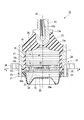
図1に示すように防振装置10は、振動発生部および振動受部のいずれか一方に連結される筒状の第1取付け部材11と、振動発生部および振動受部のいずれか他方に連結される第2取付け部材12と、これらの第1取付け部材11、第2取付け部材12同士を弾性的に連結する弾性体13と、第1取付け部材11内を後述する主液室14と副液室15とに区画する仕切り部材16と、を備える液体封入型の防振装置である。 (First embodiment)
Hereinafter, an embodiment of a vibration isolator according to the present invention will be described with reference to FIGS. 1 and 2.
As shown in FIG. 1, thevibration isolator 10 is connected to a cylindrical first mounting member 11 connected to one of the vibration generating unit and the vibration receiving unit, and to the other of the vibration generating unit and the vibration receiving unit. The second mounting member 12, the first mounting member 11, the elastic body 13 that elastically connects the second mounting members 12 to each other, the main liquid chamber 14 and the secondary liquid described later in the first mounting member 11. A liquid-sealed vibration isolator including a partition member 16 partitioned into a chamber 15.
以下、本発明に係る防振装置の実施の形態について、図1および図2に基づいて説明する。
図1に示すように防振装置10は、振動発生部および振動受部のいずれか一方に連結される筒状の第1取付け部材11と、振動発生部および振動受部のいずれか他方に連結される第2取付け部材12と、これらの第1取付け部材11、第2取付け部材12同士を弾性的に連結する弾性体13と、第1取付け部材11内を後述する主液室14と副液室15とに区画する仕切り部材16と、を備える液体封入型の防振装置である。 (First embodiment)
Hereinafter, an embodiment of a vibration isolator according to the present invention will be described with reference to FIGS. 1 and 2.
As shown in FIG. 1, the
以下、第1取付け部材11の中心軸線を軸心Oといい、軸心Oに沿う方向を軸方向という。また、軸方向に沿う第2取付け部材12側を上側、仕切り部材16側を下側という。また、防振装置10を軸方向から見た平面視において、軸心Oに直交する方向を「径方向」といい、軸心O周りに周回する方向を「周方向」という。
なお、第1取付け部材11、第2取付け部材12、および弾性体13はそれぞれ、平面視した状態で円形状若しくは円環状に形成されるとともに、軸心Oと同軸に配置されている。 Hereinafter, the central axis of thefirst mounting member 11 is referred to as an axis O, and the direction along the axis O is referred to as an axial direction. The second mounting member 12 side along the axial direction is referred to as the upper side, and the partition member 16 side is referred to as the lower side. Further, in a plan view of the vibration isolator 10 viewed from the axial direction, a direction orthogonal to the axis O is referred to as a “radial direction”, and a direction around the axis O is referred to as a “circumferential direction”.
Thefirst mounting member 11, the second mounting member 12, and the elastic body 13 are each formed in a circular shape or an annular shape in a plan view, and are disposed coaxially with the axis O.
なお、第1取付け部材11、第2取付け部材12、および弾性体13はそれぞれ、平面視した状態で円形状若しくは円環状に形成されるとともに、軸心Oと同軸に配置されている。 Hereinafter, the central axis of the
The
この防振装置10が、例えば自動車に装着される場合、第2取付け部材12が振動発生部としてのエンジンに連結され、第1取付け部材11が振動受部としての車体に連結される。これにより、エンジンの振動が車体に伝達することが抑えられる。
When the vibration isolator 10 is mounted on, for example, an automobile, the second mounting member 12 is connected to an engine as a vibration generating unit, and the first mounting member 11 is connected to a vehicle body as a vibration receiving unit. This suppresses transmission of engine vibration to the vehicle body.
第2取付け部材12は、軸方向に延在する柱状部材であり、下端部が半球面状に形成されるとともに、この半球面状の下端部より上方に鍔部12aを有している。この第2取付け部材12の上部には、その上端面から下方に向かって延びるねじ孔12bが穿設され、このねじ孔12bにエンジン側の取付け具となるボルト(図示せず)が螺合されるようになっている。また、この第2取付け部材12は、弾性体13を介して、第1取付け部材11の上端開口部側に配置されている。
The second mounting member 12 is a columnar member extending in the axial direction, and has a lower end formed in a hemispherical shape, and has a flange 12a above the lower end of the hemispherical shape. A screw hole 12b extending downward from the upper end surface of the second mounting member 12 is formed in the upper portion, and a bolt (not shown) serving as a mounting tool on the engine side is screwed into the screw hole 12b. It has become so. The second mounting member 12 is disposed on the upper end opening side of the first mounting member 11 via the elastic body 13.
弾性体13は、第1取付け部材11の上端開口部と第2取付け部材12の下端側外周面とにそれぞれ加硫接着されて、これらの間に介在させられたゴム体であって、第1取付け部材11の上端開口部を上側から閉塞している。この弾性体13は、その上端部が第2取付け部材12の鍔部12aに当接することで、第2取付け部材12に充分に密着し、該第2取付け部材12の変位により良好に追従するようになっている。また、弾性体13の下端部には、第1取付け部材11の内周面と下端開口縁の一部とを液密に被覆するゴム膜17が一体形成されている。なお、弾性体13としては、ゴム以外にも合成樹脂等からなる弾性体を用いることも可能である。
The elastic body 13 is a rubber body that is vulcanized and bonded to the upper end opening of the first mounting member 11 and the lower end side outer peripheral surface of the second mounting member 12, respectively, and interposed between them. The upper end opening of the mounting member 11 is closed from above. The elastic body 13 is sufficiently in close contact with the second mounting member 12 by the upper end of the elastic body 13 coming into contact with the flange portion 12 a of the second mounting member 12, so that the elastic body 13 follows better due to the displacement of the second mounting member 12. It has become. A rubber film 17 is integrally formed at the lower end portion of the elastic body 13 to liquid-tightly cover the inner peripheral surface of the first mounting member 11 and a part of the lower end opening edge. As the elastic body 13, an elastic body made of synthetic resin or the like can be used in addition to rubber.
第1取付け部材11は、下端部にフランジ18を有する円筒状に形成され、フランジ18を介して振動受部としての車体等に連結される。この第1取付け部材11の内部のうち、弾性体13より下方に位置する部分が、液室19となっている。本実施形態では、第1取付け部材11の下端部内に仕切り部材16が設けられ、さらにこの仕切り部材16の下方にダイヤフラム20が設けられている。
The first mounting member 11 is formed in a cylindrical shape having a flange 18 at a lower end portion, and is connected to a vehicle body or the like as a vibration receiving portion via the flange 18. A portion of the inside of the first attachment member 11 located below the elastic body 13 is a liquid chamber 19. In the present embodiment, a partition member 16 is provided in the lower end portion of the first mounting member 11, and a diaphragm 20 is further provided below the partition member 16.
ダイヤフラム20は、ゴムや軟質樹脂等の弾性材料からなり、有底円筒状に形成されている。ダイヤフラム20の上端部は、仕切り部材16と、仕切り部材16より下方に位置するリング状の保持具21と、によって軸方向に挟まれている。仕切り部材16の下面には、ダイヤフラム20の上端部が液密に係合する円環状の取付け溝16aが形成されている。仕切り部材16には、その外周に下側フランジ部22が形成されており、この下側フランジ部22の下面に前記保持具21の上面が当接している。
The diaphragm 20 is made of an elastic material such as rubber or soft resin, and is formed in a bottomed cylindrical shape. The upper end portion of the diaphragm 20 is sandwiched between the partition member 16 and the ring-shaped holder 21 positioned below the partition member 16 in the axial direction. On the lower surface of the partition member 16, an annular mounting groove 16 a is formed in which the upper end portion of the diaphragm 20 is liquid-tightly engaged. A lower flange portion 22 is formed on the outer periphery of the partition member 16, and the upper surface of the holder 21 is in contact with the lower surface of the lower flange portion 22.
このような構成のもとに、第1取付け部材11の下端開口縁に、仕切り部材16の下側フランジ部22、および保持具21が下方に向けてこの順に配置され、ねじ23によって固定されることにより、ダイヤフラム20は仕切り部材16を介して第1取付け部材11の下端開口部に取り付けられている。なお、ダイヤフラム20は、本実施形態ではその底部が、外周側で深く中央部で浅い形状になっている。ただし、ダイヤフラム20の形状としては、このような形状以外にも、従来公知の種々の形状を採用することができる。
Under such a configuration, the lower flange portion 22 of the partition member 16 and the holder 21 are disposed in this order at the lower end opening edge of the first mounting member 11 in this order, and are fixed by screws 23. Thus, the diaphragm 20 is attached to the lower end opening of the first attachment member 11 via the partition member 16. In the present embodiment, the diaphragm 20 has a bottom that is deep at the outer peripheral side and shallow at the center. However, as the shape of the diaphragm 20, various conventionally known shapes can be adopted in addition to such a shape.
そして、このように第1取付け部材11に仕切り部材16を介してダイヤフラム20が取り付けられたことにより、前記したように第1取付け部材11内に液室19が形成されている。液室19は、第1取付け部材11内、すなわち平面視して第1取付け部材11の内側に配設されたもので、弾性体13とダイヤフラム20とにより液密に封止された密閉空間となっている。そして、この液室19には、液体Lが封入(充填)されている。
And, as described above, the liquid chamber 19 is formed in the first attachment member 11 by attaching the diaphragm 20 to the first attachment member 11 via the partition member 16 in this way. The liquid chamber 19 is disposed in the first mounting member 11, that is, inside the first mounting member 11 in plan view, and is a sealed space that is liquid-tightly sealed by the elastic body 13 and the diaphragm 20. It has become. The liquid chamber 19 is filled (filled) with the liquid L.
液室19は、仕切り部材16によって主液室14と副液室15とに区画されている。主液室14は、弾性体13の下面13aを壁面の一部として形成されたもので、この弾性体13と第1取付け部材11の内周面を液密に覆うゴム膜17と仕切り部材16とによって囲まれた空間であり、弾性体13の変形によって内容積が変化する。副液室15は、ダイヤフラム20と仕切り部材16とによって囲まれた空間であり、ダイヤフラム20の変形によって内容積が変化する。このような構成からなる防振装置10は、主液室14が鉛直方向上側に位置し、副液室15が鉛直方向下側に位置するように取り付けられて用いられる、圧縮式の装置である。
The liquid chamber 19 is partitioned into a main liquid chamber 14 and a sub liquid chamber 15 by a partition member 16. The main liquid chamber 14 is formed by using the lower surface 13a of the elastic body 13 as a part of the wall surface. The rubber film 17 and the partition member 16 that cover the elastic body 13 and the inner peripheral surface of the first mounting member 11 in a liquid-tight manner. And the inner volume changes due to the deformation of the elastic body 13. The auxiliary liquid chamber 15 is a space surrounded by the diaphragm 20 and the partition member 16, and the internal volume changes due to the deformation of the diaphragm 20. The vibration isolator 10 having such a configuration is a compression-type device that is mounted and used so that the main liquid chamber 14 is positioned on the upper side in the vertical direction and the auxiliary liquid chamber 15 is positioned on the lower side in the vertical direction. .
仕切り部材16の上面のうち、下側フランジ部22の内周縁に連なる部分には、ゴム膜17の下端部を液密に保持する保持溝16bが形成されている。また、仕切り部材16の上端部には、その外周面がゴム膜17の内周面に液密に当接する環状の上側フランジ部16cが形成されている。保持溝16bおよび上側フランジ部16cによって、ゴム膜17と仕切り部材16との間が液密に閉塞されている。
A holding groove 16b that holds the lower end portion of the rubber film 17 in a liquid-tight manner is formed in a portion of the upper surface of the partition member 16 that is continuous with the inner peripheral edge of the lower flange portion 22. In addition, an annular upper flange portion 16 c whose outer peripheral surface is in liquid-tight contact with the inner peripheral surface of the rubber film 17 is formed at the upper end portion of the partition member 16. The space between the rubber film 17 and the partition member 16 is liquid-tightly closed by the holding groove 16b and the upper flange portion 16c.
また、仕切り部材16には、主液室14と副液室15とを連通する制限通路24が設けられている。
図1および図2に示すように、制限通路24は、仕切り部材16内に配置された本体流路25と、本体流路25と主液室14とを連通する第1連通部26と、本体流路25と副液室15とを連通する第2連通部27と、を備えている。
本体流路25は、仕切り部材16内で周方向に沿って延び、本体流路25の流路方向Rと周方向とは同等の方向になっている。本体流路25は、軸心Oと同軸に配置された円弧状に形成され、周方向に沿ってほぼ全周にわたって延びている。本体流路25の周方向に沿う両端部は、径方向および軸方向に延びる隔壁28aによって互いに隔てられている。
本体流路25は、主液室14に面する第1障壁28と、副液室15に面する第2障壁29と、上側フランジ部16cと、ゴム膜17と、隔壁28aと、により画成されている。なお、第1障壁28および第2障壁29は、本体流路25を画成していなくてもよい。 Further, thepartition member 16 is provided with a restriction passage 24 that allows the main liquid chamber 14 and the sub liquid chamber 15 to communicate with each other.
As shown in FIGS. 1 and 2, therestriction passage 24 includes a main body flow path 25 disposed in the partition member 16, a first communication portion 26 that communicates the main body flow path 25 and the main liquid chamber 14, and a main body. And a second communication portion 27 that communicates the flow path 25 and the auxiliary liquid chamber 15.
The mainbody flow path 25 extends along the circumferential direction in the partition member 16, and the flow path direction R and the circumferential direction of the main body flow path 25 are in the same direction. The main body flow path 25 is formed in an arc shape arranged coaxially with the axial center O, and extends over the entire circumference along the circumferential direction. Both end portions along the circumferential direction of the main body flow path 25 are separated from each other by partition walls 28a extending in the radial direction and the axial direction.
The mainbody flow path 25 is defined by the first barrier 28 facing the main liquid chamber 14, the second barrier 29 facing the sub liquid chamber 15, the upper flange portion 16c, the rubber film 17, and the partition wall 28a. Has been. Note that the first barrier 28 and the second barrier 29 may not define the main body flow path 25.
図1および図2に示すように、制限通路24は、仕切り部材16内に配置された本体流路25と、本体流路25と主液室14とを連通する第1連通部26と、本体流路25と副液室15とを連通する第2連通部27と、を備えている。
本体流路25は、仕切り部材16内で周方向に沿って延び、本体流路25の流路方向Rと周方向とは同等の方向になっている。本体流路25は、軸心Oと同軸に配置された円弧状に形成され、周方向に沿ってほぼ全周にわたって延びている。本体流路25の周方向に沿う両端部は、径方向および軸方向に延びる隔壁28aによって互いに隔てられている。
本体流路25は、主液室14に面する第1障壁28と、副液室15に面する第2障壁29と、上側フランジ部16cと、ゴム膜17と、隔壁28aと、により画成されている。なお、第1障壁28および第2障壁29は、本体流路25を画成していなくてもよい。 Further, the
As shown in FIGS. 1 and 2, the
The main
The main
第1障壁28は、上側フランジ部16cの内周縁から下方に向けて延びる筒状に形成されている。図2に示すように、第1障壁28の外周面のうち、第1連通部26が配設されている部分が、第2連通部27から流路方向Rに離間するに従い漸次径方向の外側に向かっている。このため、本体流路25のうち、第1連通部26との接続部分25aにおける流路面積は、第2連通部27から流路方向Rに離間するに従い、漸次小さくなっている。
第2障壁29は、表裏面が軸方向を向く板状に形成されている。第2障壁29の上面と、第1障壁28の下端と、は互いに連なっている。第1障壁28は、本体流路25と主液室14とに径方向に挟まれ、本体流路25と主液室14との間に位置している。第2障壁29は、本体流路25と副液室15とに軸方向に挟まれ、本体流路25と副液室15との間に位置している。 Thefirst barrier 28 is formed in a cylindrical shape extending downward from the inner peripheral edge of the upper flange portion 16c. As shown in FIG. 2, the portion of the outer peripheral surface of the first barrier 28 where the first communication portion 26 is disposed gradually increases in the outer radial direction as the distance from the second communication portion 27 in the flow path direction R increases. Heading to For this reason, in the main body channel 25, the channel area at the connection portion 25 a with the first communication part 26 gradually decreases as the distance from the second communication part 27 in the channel direction R increases.
Thesecond barrier 29 is formed in a plate shape whose front and back surfaces face the axial direction. The upper surface of the second barrier 29 and the lower end of the first barrier 28 are connected to each other. The first barrier 28 is sandwiched between the main body flow path 25 and the main liquid chamber 14 in the radial direction, and is positioned between the main body flow path 25 and the main liquid chamber 14. The second barrier 29 is sandwiched between the main body flow path 25 and the secondary liquid chamber 15 in the axial direction, and is positioned between the main body flow path 25 and the secondary liquid chamber 15.
第2障壁29は、表裏面が軸方向を向く板状に形成されている。第2障壁29の上面と、第1障壁28の下端と、は互いに連なっている。第1障壁28は、本体流路25と主液室14とに径方向に挟まれ、本体流路25と主液室14との間に位置している。第2障壁29は、本体流路25と副液室15とに軸方向に挟まれ、本体流路25と副液室15との間に位置している。 The
The
第1連通部26は、第1障壁28を径方向に貫通し、流路方向Rに沿って配置された複数の細孔26aを備えている。複数の細孔26aは、第1障壁28のうち、本体流路25の周方向に沿う一方側の端部を形成する部分に配置されている。
第2連通部27は、第2障壁29を軸方向に貫通する開口である。第2連通部27は、第2障壁29のうち、本体流路25の周方向に沿う他方側の端部を形成する部分に配置されている。 Thefirst communication portion 26 includes a plurality of pores 26 a that penetrate the first barrier 28 in the radial direction and are disposed along the flow path direction R. The plurality of pores 26 a are arranged in a portion of the first barrier 28 that forms one end portion along the circumferential direction of the main body flow path 25.
Thesecond communication portion 27 is an opening that penetrates the second barrier 29 in the axial direction. The second communication portion 27 is disposed in a portion of the second barrier 29 that forms the other end portion along the circumferential direction of the main body flow path 25.
第2連通部27は、第2障壁29を軸方向に貫通する開口である。第2連通部27は、第2障壁29のうち、本体流路25の周方向に沿う他方側の端部を形成する部分に配置されている。 The
The
複数の細孔26aは、いずれも直方体状に形成されている。複数の細孔26aの主液室14に向けた開口部はいずれも、径方向の内側から見た正面視において、周方向よりも軸方向に長い長方形状に形成されている。複数の細孔26aの流路断面積は、各細孔26aの流路長さの全長にわたって同等となっている。複数の細孔26aの周方向の幅は、それぞれ互いに同等となっている。複数の細孔26aは、それぞれ周方向に同等の間隔をあけて配置されている。
また、複数の細孔26aの軸方向の長さは、第2連通部27から流路方向Rに離間して位置するものほど小さくなっている。このため、複数の細孔26aは、第2連通部27から流路方向Rに離間して位置するものほど、最小横断面の投影面積または開口面積が小さくなっている。その結果、第1障壁28のうち、主液室14に面する内周面における所定面積あたりに占める、細孔26aの最小横断面の投影面積または開口面積の割合が、第2連通部27から流路方向Rに離間するに従い、漸次小さくなっている。
また、複数の細孔26aは、第2連通部27から流路方向Rに離間して位置するものほど、流路長さが長くなっている。
以上により、複数の細孔26aは、第2連通部27から流路方向Rに離間して位置するものほど、その細孔26aを液体Lが流通する際の抵抗が大きくなっている。
なお、「投影面積」とは、第1障壁28または第2障壁29における、主液室14内または副液室15内に位置する面への、細孔26aの最小横断面の中央を通る細孔中心線が延びる方向に向けた投影面積をいう。 The plurality ofpores 26a are all formed in a rectangular parallelepiped shape. The openings of the plurality of pores 26a toward the main liquid chamber 14 are all formed in a rectangular shape that is longer in the axial direction than in the circumferential direction when viewed from the inside in the radial direction. The channel cross-sectional areas of the plurality of pores 26a are the same over the entire length of the channel length of each pore 26a. The circumferential widths of the plurality of pores 26a are equal to each other. The plurality of pores 26a are arranged at equal intervals in the circumferential direction.
In addition, the axial lengths of the plurality ofpores 26a are smaller as they are spaced apart from the second communication portion 27 in the flow direction R. For this reason, the projected area or the opening area of the minimum cross section is smaller as the plurality of pores 26a are positioned away from the second communication portion 27 in the flow path direction R. As a result, the ratio of the projected area or the opening area of the minimum cross section of the pore 26 a occupying per predetermined area on the inner peripheral surface facing the main liquid chamber 14 in the first barrier 28 is from the second communication portion 27. As the distance in the flow path direction R increases, the distance gradually decreases.
The plurality ofpores 26a have a longer channel length as they are spaced from the second communicating portion 27 in the channel direction R.
As described above, as the plurality ofpores 26a are spaced apart from the second communication portion 27 in the flow direction R, the resistance when the liquid L flows through the pores 26a increases.
Note that the “projection area” is a narrow area passing through the center of the minimum cross section of thepore 26a to the surface of the first barrier 28 or the second barrier 29 located in the main liquid chamber 14 or the sub liquid chamber 15. The projected area in the direction in which the hole center line extends.
また、複数の細孔26aの軸方向の長さは、第2連通部27から流路方向Rに離間して位置するものほど小さくなっている。このため、複数の細孔26aは、第2連通部27から流路方向Rに離間して位置するものほど、最小横断面の投影面積または開口面積が小さくなっている。その結果、第1障壁28のうち、主液室14に面する内周面における所定面積あたりに占める、細孔26aの最小横断面の投影面積または開口面積の割合が、第2連通部27から流路方向Rに離間するに従い、漸次小さくなっている。
また、複数の細孔26aは、第2連通部27から流路方向Rに離間して位置するものほど、流路長さが長くなっている。
以上により、複数の細孔26aは、第2連通部27から流路方向Rに離間して位置するものほど、その細孔26aを液体Lが流通する際の抵抗が大きくなっている。
なお、「投影面積」とは、第1障壁28または第2障壁29における、主液室14内または副液室15内に位置する面への、細孔26aの最小横断面の中央を通る細孔中心線が延びる方向に向けた投影面積をいう。 The plurality of
In addition, the axial lengths of the plurality of
The plurality of
As described above, as the plurality of
Note that the “projection area” is a narrow area passing through the center of the minimum cross section of the
このような構成からなる防振装置10では、振動入力時に、両取付け部材11、12が弾性体13を弾性変形させながら相対的に変位する。すると、主液室14の液圧が変動し、主液室14内の液体Lが制限通路24を通って副液室15に流入し、また、副液室15内の液体Lが制限通路24を通って主液室14に流入する。すなわち、副液室15内の液体Lの一部が主液室14に戻る。このとき、例えば、主液室14が負圧化されることによって液体Lが一部蒸発して気泡が生成され、キャビテーション崩壊が生じる。あるいは、本体流路25を流通して第1連通部26に向かう液体Lの流れが、複数の細孔26aを慣性により通過した後、隔壁28aに衝突し、複数の細孔26aのうち隔壁28a寄りに位置するものから偏って主液室14内に流入することで、複数の細孔26aを通過した液体Lの流速が局所的に速くなり、気泡の生成およびキャビテーション崩壊が生じる場合がある。
In the vibration isolator 10 having such a configuration, the two attachment members 11 and 12 are relatively displaced while elastically deforming the elastic body 13 at the time of vibration input. Then, the liquid pressure in the main liquid chamber 14 fluctuates, the liquid L in the main liquid chamber 14 flows into the sub liquid chamber 15 through the restriction passage 24, and the liquid L in the sub liquid chamber 15 flows into the restriction passage 24. Through the main liquid chamber 14. That is, a part of the liquid L in the sub liquid chamber 15 returns to the main liquid chamber 14. At this time, for example, due to the negative pressure in the main liquid chamber 14, the liquid L partially evaporates and bubbles are generated, causing cavitation collapse. Or after the flow of the liquid L which distribute | circulates the main body flow path 25 and goes to the 1st communication part 26 passes through the several pore 26a by inertia, it collides with the partition 28a, The partition 28a among several pore 26a By flowing in the main liquid chamber 14 in a biased manner from the one located closer, the flow rate of the liquid L that has passed through the plurality of pores 26a is locally increased, and bubbles may be generated and cavitation collapse may occur.
本実施形態に係る防振装置10によれば、液体Lが本体流路25から、複数の細孔26aを通して主液室14に流出するときには、これらの細孔26aが形成された第1障壁28により圧力損失を生じながら液体Lが各細孔26aを流通するため、各細孔26aを流通する液体Lの流速の上昇を抑えることができる。しかも、液体Lが、単一の細孔26aではなく複数の細孔26aを流通するので、液体Lを複数に分岐させて流通させることが可能になり、個々の細孔26aを通過した液体Lの流速を低減させることができる。これにより、細孔26aを通過して主液室14に流入した液体Lと、主液室14内の液体Lと、の間で生じる流速差を小さく抑え、流速差に起因する渦の発生、およびこの渦に起因する気泡の発生を抑えることができる。
According to the vibration isolator 10 according to the present embodiment, when the liquid L flows from the main body flow path 25 to the main liquid chamber 14 through the plurality of pores 26a, the first barrier 28 in which these pores 26a are formed. As a result, the liquid L flows through each pore 26a while causing a pressure loss, so that an increase in the flow velocity of the liquid L flowing through each pore 26a can be suppressed. Moreover, since the liquid L circulates through the plurality of pores 26a instead of the single pore 26a, the liquid L can be branched and circulated, and the liquid L that has passed through the individual pores 26a. The flow rate of can be reduced. Thereby, the flow velocity difference generated between the liquid L that has flowed into the main liquid chamber 14 through the pores 26a and the liquid L in the main liquid chamber 14 is suppressed, and the generation of vortices due to the flow velocity difference is generated. And generation | occurrence | production of the bubble resulting from this vortex can be suppressed.
さらに、第1障壁28のうち、主液室14に面する内周面における所定面積当たりに占める、各細孔26aの最小横断面の投影面積または開口面積の割合が、第2連通部27から流路方向Rに離間するに従い漸次小さくなっているので、制限通路24内を流れる液体Lが、第2連通部27から第1連通部26に到達したときに、複数の細孔26aのうち、流路方向Rの第2連通部27側に位置する細孔26aを第1連通部26側に慣性力によって通過してしまうのを抑制することができる。これにより、この第2連通部27側に位置する細孔26aからも液体Lを流出させやすくなり、各細孔26aから流出する液体Lの流速を均一化して局所的に速くなるのを抑えて、気泡の発生およびキャビテーション崩壊に起因する異音の発生をより効果的に抑止することができる。
Furthermore, the ratio of the projected area or the opening area of the minimum cross section of each pore 26 a occupying per predetermined area on the inner peripheral surface facing the main liquid chamber 14 in the first barrier 28 is from the second communication portion 27. Since the liquid L flowing in the restriction passage 24 reaches the first communication portion 26 from the second communication portion 27, among the plurality of pores 26 a, since it gradually decreases as the distance in the flow path direction R increases. It is possible to suppress passage of the pores 26a located on the second communication portion 27 side in the flow path direction R to the first communication portion 26 side due to inertial force. As a result, the liquid L can easily flow out from the pores 26a located on the second communication portion 27 side, and the flow velocity of the liquid L flowing out from the respective pores 26a is made uniform to suppress local increase. In addition, it is possible to more effectively suppress the generation of air bubbles due to the generation of bubbles and the collapse of cavitation.
また、複数の細孔26aは、第2連通部27から流路方向Rに離間して位置するものほど、最小横断面の投影面積または開口面積が小さくなっていることにより、第1障壁28のうち、主液室14に面する内周面における所定面積あたりに占める、各細孔26aの最小横断面の投影面積または開口面積の割合が、第2連通部27から流路方向Rに離間するに従い、漸次小さくなる構造を簡易な構成で確実に実現することができる。
In addition, since the plurality of pores 26a are located away from the second communication portion 27 in the flow path direction R, the projected area or the opening area of the minimum cross section is smaller, so Among these, the ratio of the projected area or the opening area of the minimum cross section of each pore 26 a occupying per predetermined area on the inner peripheral surface facing the main liquid chamber 14 is separated from the second communication portion 27 in the flow direction R. Accordingly, a structure that gradually decreases can be reliably realized with a simple configuration.
また、複数の細孔26aは、第2連通部27から流路方向Rに離間して位置するものほど、その流路長さが長くなっているため、複数の細孔26aのうち、流路方向Rの第1連通部26側に位置する細孔26aを流通する液体Lの圧力損失を大きくすることが可能となり、複数の細孔26aのうち、流路方向Rの第1連通部26側に位置する細孔26aから大量の液体が高速で流出するのを抑制することができる。
Moreover, since the flow path length is so long that the some pore 26a is located in the flow direction R from the 2nd communication part 27, the flow path length becomes long, Therefore It becomes possible to increase the pressure loss of the liquid L flowing through the pores 26a located on the first communication portion 26 side in the direction R, and among the plurality of pores 26a, the first communication portion 26 side in the flow direction R. It is possible to prevent a large amount of liquid from flowing out at high speed from the pores 26a located at the positions.
また、本体流路25のうち、第1連通部26との接続部分25aにおける流路面積が、第2連通部27から流路方向Rに離間するに従い漸次小さくなっているため、液体Lが接続部分25aを流通する過程で漸次流通抵抗が増して液体Lの流速が抑えられる。これにより、慣性によって液体Lが流路方向Rの第2連通部27側に位置する細孔26aを通過するのを抑止し、第2連通部27側の細孔26aからも液体を流出させやすくなり、流路方向Rの第1連通部26側に位置する細孔26aから大量の液体Lが高速で流出するのを確実に抑えることができる。
Further, in the main body flow channel 25, the flow channel area at the connection portion 25a with the first communication portion 26 gradually decreases as the distance from the second communication portion 27 in the flow channel direction R decreases. In the process of flowing through the portion 25a, the flow resistance gradually increases and the flow velocity of the liquid L is suppressed. This prevents the liquid L from passing through the pores 26a located on the second communication portion 27 side in the flow path direction R due to inertia, and allows the liquid to easily flow out from the pores 26a on the second communication portion 27 side. Thus, it is possible to reliably suppress a large amount of liquid L from flowing out at high speed from the pores 26a located on the first communication portion 26 side in the flow path direction R.
(第2実施形態)
次に、本発明に係る第2実施形態について説明するが、第1実施形態と基本的な構成は同様である。このため、同様の構成には同一の符号を付してその説明は省略し、異なる点についてのみ説明する。
本実施形態では、複数の細孔26aが配置されている周方向の間隔が異なる。 (Second Embodiment)
Next, a second embodiment according to the present invention will be described. The basic configuration is the same as that of the first embodiment. For this reason, the same code | symbol is attached | subjected to the same structure, the description is abbreviate | omitted, and only a different point is demonstrated.
In the present embodiment, the circumferential intervals at which the plurality ofpores 26a are arranged are different.
次に、本発明に係る第2実施形態について説明するが、第1実施形態と基本的な構成は同様である。このため、同様の構成には同一の符号を付してその説明は省略し、異なる点についてのみ説明する。
本実施形態では、複数の細孔26aが配置されている周方向の間隔が異なる。 (Second Embodiment)
Next, a second embodiment according to the present invention will be described. The basic configuration is the same as that of the first embodiment. For this reason, the same code | symbol is attached | subjected to the same structure, the description is abbreviate | omitted, and only a different point is demonstrated.
In the present embodiment, the circumferential intervals at which the plurality of
図3に示すように、本実施形態における複数の細孔26aが配置されている周方向の間隔は均一ではない。詳しくは、流路方向Rで互いに隣り合う細孔26a同士の間隔は、第2連通部から流路方向Rに離間するに従い、漸次広くなっている。
As shown in FIG. 3, the circumferential interval at which the plurality of pores 26a in this embodiment are arranged is not uniform. Specifically, the interval between the pores 26a adjacent to each other in the flow path direction R gradually increases as the distance from the second communication portion increases in the flow path direction R.
本実施形態によれば、流路方向Rで互いに隣り合う細孔26a同士の間隔が、第2連通部から流路方向Rに離間するに従い、漸次広くなっていることにより、第1障壁28のうち、主液室14に面する内周面における所定面積あたりに占める、各細孔26aの最小横断面の投影面積または開口面積の割合が、第2連通部27から流路方向Rに離間するに従い、漸次小さくなる構造を簡易な構成で確実に実現することができる。
According to the present embodiment, the interval between the pores 26a adjacent to each other in the flow path direction R gradually increases as the distance from the second communicating portion in the flow path direction R increases. Among these, the ratio of the projected area or the opening area of the minimum cross section of each pore 26 a occupying per predetermined area on the inner peripheral surface facing the main liquid chamber 14 is separated from the second communication portion 27 in the flow direction R. Accordingly, a structure that gradually decreases can be reliably realized with a simple configuration.
なお、本発明の技術的範囲は前記実施形態に限定されるものではなく、本発明の趣旨を逸脱しない範囲において種々の変更を加えることが可能である。
The technical scope of the present invention is not limited to the above-described embodiment, and various modifications can be made without departing from the spirit of the present invention.
例えば、前記実施形態では、第1連通部26が複数の細孔26aを備えているが、本発明はこれに限られない。例えば、第2連通部27が、流路方向Rに沿って配置された複数の細孔を備えていてもよい。この場合には、第2障壁29のうち、副液室15に面する下面の所定面積あたりに占める細孔の最小横断面の投影面積または開口面積の割合が、第1連通部26から流路方向Rに離間するに従い、漸次小さくなっていてもよい。この場合の複数の細孔は、第2障壁29を軸方向に貫通していてもよい。また、この場合の複数の細孔は、第1連通部26から流路方向Rに離間して位置するものほど、最小横断面の投影面積または開口面積が小さくなっていてもよい。また、この場合の複数の細孔は、第1連通部26から流路方向Rに離間して位置するものほど、その流路長さが長くなっていてもよい。また、この場合には、流路方向Rで互いに隣り合う細孔同士の間隔が、第1連通部から流路方向Rに離間するに従い、漸次広くなっていてもよい。また、この場合には、第1連通部26に複数の細孔26aが形成されていなくてもよい。
For example, in the above-described embodiment, the first communication portion 26 includes a plurality of pores 26a, but the present invention is not limited to this. For example, the second communication portion 27 may include a plurality of pores arranged along the flow path direction R. In this case, the ratio of the projected area or the opening area of the minimum cross section of the pores per predetermined area of the lower surface facing the secondary liquid chamber 15 in the second barrier 29 is determined from the first communication part 26 to the flow path. As the distance in the direction R increases, the distance may gradually decrease. The plurality of pores in this case may penetrate the second barrier 29 in the axial direction. In addition, in this case, the projected area or the opening area of the minimum cross section may be smaller as the plurality of fine pores are spaced apart from the first communication portion 26 in the flow path direction R. In addition, the plurality of pores in this case may have a longer channel length as they are positioned away from the first communication portion 26 in the channel direction R. In this case, the interval between the pores adjacent to each other in the flow path direction R may gradually increase as the distance from the first communication portion increases in the flow path direction R. In this case, the plurality of pores 26 a may not be formed in the first communication portion 26.
また、前記実施形態では、本体流路25のうち、第1連通部26との接続部分25aにおける流路面積が第2連通部27から流路方向Rに離間するに従い漸次小さくなっていたが、本体流路25のうち、第2連通部27との接続部分における流路面積が第1連通部26から流路方向Rに離間するに従い漸次小さくなっていてもよい。
また、本体流路25のうち接続部分25aの流路面積を第2連通部27から流路方向Rに離間するに従い漸次小さくするために、例えば接続部分25aにおける本体流路25の軸方向の幅を、第2連通部27から流路方向Rに離間するに従い、漸次小さくなるように仕切り部材16を形成してもよい。 Further, in the embodiment, the flow passage area in theconnection portion 25a with the first communication portion 26 in the main body flow passage 25 gradually decreases as the flow passage direction R is separated from the second communication portion 27. In the main body flow path 25, the flow area at the connection portion with the second communication portion 27 may gradually decrease as the distance from the first communication portion 26 in the flow direction R is increased.
Further, in order to gradually reduce the flow channel area of theconnection portion 25a in the main body flow channel 25 from the second communication portion 27 in the flow direction R, for example, the axial width of the main flow channel 25 in the connection portion 25a, for example. The partition member 16 may be formed so as to gradually decrease as the distance from the second communication portion 27 increases in the flow path direction R.
また、本体流路25のうち接続部分25aの流路面積を第2連通部27から流路方向Rに離間するに従い漸次小さくするために、例えば接続部分25aにおける本体流路25の軸方向の幅を、第2連通部27から流路方向Rに離間するに従い、漸次小さくなるように仕切り部材16を形成してもよい。 Further, in the embodiment, the flow passage area in the
Further, in order to gradually reduce the flow channel area of the
また、前記実施形態では細孔26aを長方形状に形成したが、円柱状や円錐状に形成してもよい。
また、前記実施形態では細孔26aの流路断面積が、その流路長さの全長にわたって同等となっていたが、流路断面積が変化する細孔26aを採用してもよい。
また、前記実施形態では複数の細孔26aが流路方向Rに沿って配置されているが、複数の細孔26aが流路方向Rに沿い、かつ軸方向に沿って配置されていてもよい。
また、前記実施形態では、本体流路25が周方向に延びて配置されているが、本発明はこれに限られない。 Moreover, although thepore 26a was formed in the rectangular shape in the said embodiment, you may form in a column shape or a cone shape.
In the above embodiment, the channel cross-sectional area of thepores 26a is the same over the entire length of the channel length, but the pores 26a whose channel cross-sectional area changes may be adopted.
In the above embodiment, the plurality ofpores 26a are arranged along the flow path direction R. However, the plurality of pores 26a may be arranged along the flow path direction R and along the axial direction. .
Moreover, in the said embodiment, although the mainbody flow path 25 is extended and arrange | positioned in the circumferential direction, this invention is not limited to this.
また、前記実施形態では細孔26aの流路断面積が、その流路長さの全長にわたって同等となっていたが、流路断面積が変化する細孔26aを採用してもよい。
また、前記実施形態では複数の細孔26aが流路方向Rに沿って配置されているが、複数の細孔26aが流路方向Rに沿い、かつ軸方向に沿って配置されていてもよい。
また、前記実施形態では、本体流路25が周方向に延びて配置されているが、本発明はこれに限られない。 Moreover, although the
In the above embodiment, the channel cross-sectional area of the
In the above embodiment, the plurality of
Moreover, in the said embodiment, although the main
また、前記実施形態では、仕切り部材16を第1取付け部材11の下端部に配置し、該仕切り部材16の下側フランジ部22を第1取付け部材11の下端面に当接させているが、例えば仕切り部材16を第1取付け部材11の下端面より充分上方に配置し、この仕切り部材16の下側、すなわち第1取付け部材11の下端部にダイヤフラム20を配設することで、第1取付け部材11の下端部からダイヤフラム20の底面にかけて副液室15を形成してもよい。
In the embodiment, the partition member 16 is disposed at the lower end portion of the first mounting member 11, and the lower flange portion 22 of the partition member 16 is brought into contact with the lower end surface of the first mounting member 11. For example, the partition member 16 is disposed sufficiently above the lower end surface of the first mounting member 11, and the diaphragm 20 is disposed on the lower side of the partition member 16, that is, the lower end portion of the first mounting member 11. The secondary liquid chamber 15 may be formed from the lower end of the member 11 to the bottom surface of the diaphragm 20.
また、前記実施形態では、支持荷重が作用することで主液室14に正圧が作用する圧縮式の防振装置10について説明したが、主液室14が鉛直方向下側に位置し、かつ副液室15が鉛直方向上側に位置するように取り付けられ、支持荷重が作用することで主液室14に負圧が作用する吊り下げ式の防振装置にも適用可能である。
Moreover, in the said embodiment, although the compression type vibration isolator 10 which a positive pressure acts on the main liquid chamber 14 by the support load acting was demonstrated, the main liquid chamber 14 is located in the vertical lower side, and The auxiliary liquid chamber 15 is mounted so as to be positioned on the upper side in the vertical direction, and can be applied to a suspension type vibration isolator in which a negative pressure is applied to the main liquid chamber 14 when a support load is applied.
また前記実施形態では、仕切り部材16が、第1取付け部材11内の液室19を、弾性体13を壁面の一部に有する主液室14、および副液室15に仕切るものとしたが、これに限られるものではない。例えば、ダイヤフラム20を設けるのに代えて、弾性体13を軸方向に一対設けて、副液室15を設けるのに代えて、弾性体13を壁面の一部に有する受圧液室を設けてもよい。例えば、仕切り部材16が、液体Lが封入される第1取付け部材11内の液室19を、第1液室14および第2液室15に仕切り、第1液室14および第2液室15の両液室のうちの少なくとも1つが、弾性体13を壁面の一部に有する他の構成に適宜変更することが可能である。
In the embodiment, the partition member 16 partitions the liquid chamber 19 in the first mounting member 11 into the main liquid chamber 14 having the elastic body 13 as a part of the wall surface and the sub liquid chamber 15. It is not limited to this. For example, instead of providing the diaphragm 20, a pair of elastic bodies 13 may be provided in the axial direction, and instead of providing the auxiliary liquid chamber 15, a pressure receiving liquid chamber having the elastic body 13 at a part of the wall surface may be provided. Good. For example, the partition member 16 partitions the liquid chamber 19 in the first mounting member 11 in which the liquid L is enclosed into the first liquid chamber 14 and the second liquid chamber 15, and the first liquid chamber 14 and the second liquid chamber 15. At least one of the two liquid chambers can be appropriately changed to another configuration having the elastic body 13 in a part of the wall surface.
また、本発明に係る防振装置10は、車両のエンジンマウントに限定されるものではなく、エンジンマウント以外に適用することも可能である。例えば、建設機械に搭載された発電機のマウントにも適用することも可能であり、或いは、工場等に設置される機械のマウントにも適用することも可能である。
Further, the vibration isolator 10 according to the present invention is not limited to the engine mount of the vehicle, and can be applied to other than the engine mount. For example, the present invention can be applied to a mount of a generator mounted on a construction machine, or can be applied to a mount of a machine installed in a factory or the like.
本発明の防振装置によれば、振動入力時に、両取付け部材が弾性体を弾性変形させながら相対的に変位して第1液室の液圧が変動し、液体が制限通路を通って第1液室と第2液室との間を流通しようとする。このとき液体は、第1連通部および第2連通部のうちの一方を通して本体流路に流入した後、第1連通部および第2連通部のうちの他方を通して本体流路から流出する。
ここで、防振装置に大きな荷重(振動)が入力された場合であって、液体が本体流路から、第1連通部または第2連通部に備えられた複数の細孔を通して流出するときには、これらの細孔が形成された第1障壁または第2障壁により圧力損失を生じながら液体が各細孔を流通するため、各細孔を流通する液体の流速を抑えることができる。しかも、液体が、単一の細孔ではなく複数の細孔を流通するので、液体を複数に分岐させて流通させることが可能になり、個々の細孔を通過した液体の流速を低減させることができる。これにより、細孔を通過して第1液室または第2液室に流入した液体と、第1液室内または第2液室内の液体と、の間で生じる流速差を小さく抑え、流速差に起因する渦の発生、およびこの渦に起因する気泡の発生を抑えることができる。
さらに、第1障壁若しくは第2障壁における所定面積当たりに占める、各細孔の最小横断面の投影面積または開口面積の割合が、第1連通部および第2連通部のうちのいずれか他方から流路方向に離間するに従い漸次小さくなっているので、制限通路内を流れる液体が、第1連通部および第2連通部のうちのいずれか一方に到達したときに、複数の細孔のうち、流路方向の他方側に位置する細孔を慣性力によって通過してしまうのを抑制することができる。これにより、この他方側に位置する細孔からも液体を流出させやすくなり、各細孔から流出する液体の流速を均一化して局所的に速くなるのを抑えて、気泡の発生およびキャビテーション崩壊に起因する異音の発生をより効果的に抑止することができる。 According to the vibration isolator of the present invention, at the time of vibration input, the two attachment members are relatively displaced while elastically deforming the elastic body, the liquid pressure in the first liquid chamber is fluctuated, and the liquid passes through the restriction passage. An attempt is made to circulate between the first liquid chamber and the second liquid chamber. At this time, the liquid flows into the main body flow path through one of the first communication section and the second communication section, and then flows out from the main flow path through the other of the first communication section and the second communication section.
Here, when a large load (vibration) is input to the vibration isolator, and when the liquid flows out from the main body flow path through the plurality of pores provided in the first communication portion or the second communication portion, Since the liquid flows through each pore while causing a pressure loss by the first barrier or the second barrier in which these pores are formed, the flow rate of the liquid flowing through each pore can be suppressed. In addition, since the liquid flows through a plurality of pores instead of a single pore, it is possible to divide the liquid into a plurality of channels and reduce the flow rate of the liquid that has passed through the individual pores. Can do. As a result, the flow rate difference between the liquid that has passed through the pores and flowed into the first liquid chamber or the second liquid chamber and the liquid in the first liquid chamber or the second liquid chamber is suppressed to a small value. It is possible to suppress the generation of vortices caused and the generation of bubbles due to the vortices.
Furthermore, the ratio of the projected area or the opening area of the minimum cross section of each pore per predetermined area in the first barrier or the second barrier flows from either one of the first communication portion and the second communication portion. Since the liquid gradually decreases as the distance in the road direction increases, when the liquid flowing in the restriction passage reaches one of the first communication portion and the second communication portion, the flow of the plurality of pores is reduced. It is possible to suppress the passage of pores located on the other side in the road direction due to inertial force. This makes it easier for liquid to flow out from the pores located on the other side, uniformizing the flow velocity of the liquid flowing out from each pore, and suppressing local increase in speed, resulting in bubble generation and cavitation collapse. It is possible to more effectively suppress the occurrence of abnormal noise.
ここで、前記複数の細孔は、前記第1連通部および前記第2連通部のうちのいずれか他方から前記流路方向に離間して位置するものほど、最小横断面の投影面積または開口面積が小さくなっていてもよい。
Here, the projected area or the opening area of the minimum cross section is such that the plurality of fine pores are located away from either one of the first communication portion and the second communication portion in the flow path direction. May be smaller.
この場合、第1障壁若しくは第2障壁における所定面積あたりに占める、各細孔の最小横断面の投影面積または開口面積の割合が、第1連通部および第2連通部のうちのいずれか他方から流路方向に離間するに従い、漸次小さくなる構造を簡易な構成で確実に実現することができる。
In this case, the ratio of the projected area or the opening area of the minimum cross section of each pore occupying per predetermined area in the first barrier or the second barrier is from either one of the first communication part and the second communication part. A structure that gradually decreases as the distance in the flow path direction increases can be reliably realized with a simple configuration.
また、前記流路方向で互いに隣り合う前記細孔同士の間隔は、前記第1連通部および前記第2連通部のうちのいずれか他方から前記流路方向に離間するに従い、漸次広くなっていてもよい。
In addition, the interval between the pores adjacent to each other in the flow channel direction gradually increases as the distance from the other of the first communication portion and the second communication portion increases in the flow channel direction. Also good.
この場合、第1障壁若しくは第2障壁における所定面積あたりに占める、各細孔の最小横断面の投影面積または開口面積の割合が、第1連通部および第2連通部のうちのいずれか他方から流路方向に離間するに従い、漸次小さくなる構造を簡易な構成で確実に実現することができる。
In this case, the ratio of the projected area or the opening area of the minimum cross section of each pore occupying per predetermined area in the first barrier or the second barrier is from either one of the first communication part and the second communication part. A structure that gradually decreases as the distance in the flow path direction increases can be reliably realized with a simple configuration.
その他、本発明の趣旨に逸脱しない範囲で、前記実施形態における構成要素を周知の構成要素に置き換えることは適宜可能であり、また、前記した変形例を適宜組み合わせてもよい。
In addition, it is possible to appropriately replace the constituent elements in the embodiment with well-known constituent elements without departing from the spirit of the present invention, and the above-described modified examples may be appropriately combined.
本発明によれば、簡易な構造で防振特性を低下させることなく、キャビテーション崩壊に起因する異音の発生を抑えることができる防振装置を提供することができる。
According to the present invention, it is possible to provide a vibration isolator that can suppress the occurrence of abnormal noise due to cavitation collapse without reducing the vibration isolation characteristics with a simple structure.
10 防振装置
11 第1取付け部材
12 第2取付け部材
13 弾性体
14 主液室(第1液室)
15 副液室(第2液室)
16 仕切り部材
19 液室
24 制限通路
25 本体流路
25a 接続部分
26 第1連通部
27 第2連通部
28 第1障壁
29 第2障壁
31 第1開口部(開口部)
L 液体 10vibration isolator 11 first mounting member 12 second mounting member 13 elastic body 14 main liquid chamber (first liquid chamber)
15 Secondary liquid chamber (second liquid chamber)
16Partition member 19 Liquid chamber 24 Restriction passage 25 Main body flow path 25a Connection portion 26 First communication portion 27 Second communication portion 28 First barrier 29 Second barrier 31 First opening (opening)
L liquid
11 第1取付け部材
12 第2取付け部材
13 弾性体
14 主液室(第1液室)
15 副液室(第2液室)
16 仕切り部材
19 液室
24 制限通路
25 本体流路
25a 接続部分
26 第1連通部
27 第2連通部
28 第1障壁
29 第2障壁
31 第1開口部(開口部)
L 液体 10
15 Secondary liquid chamber (second liquid chamber)
16
L liquid
Claims (3)
- 振動発生部および振動受部のうちのいずれか一方に連結される筒状の第1取付け部材、および他方に連結される第2取付け部材と、
これら両取付け部材を弾性的に連結する弾性体と、
液体が封入された前記第1取付け部材内の液室を第1液室と第2液室とに区画する仕切り部材と、を備えるとともに、
前記仕切り部材に、前記第1液室と前記第2液室とを連通する制限通路が形成された液体封入型の防振装置であって、
前記制限通路は、
前記第1液室に面する第1障壁に形成されるとともに、前記第1液室に開口する第1連通部、前記第2液室に面する第2障壁に形成されるとともに、前記第2液室に開口する第2連通部、および前記第1連通部と前記第2連通部とを連通する本体流路を備え、
前記第1連通部および前記第2連通部のうちの少なくとも一方は、前記第1障壁または前記第2障壁を貫通し、前記本体流路の流路方向に沿って配置された複数の細孔を備え、
前記第1障壁、若しくは前記第2障壁における所定面積当たりに占める、前記細孔における最小横断面の投影面積または開口面積の割合が、前記第1連通部および前記第2連通部のうちのいずれか他方から前記流路方向に離間するに従い、漸次小さくなっている防振装置。 A cylindrical first mounting member coupled to one of the vibration generating unit and the vibration receiving unit, and a second mounting member coupled to the other;
An elastic body that elastically connects both the mounting members;
A partition member that divides the liquid chamber in the first mounting member in which the liquid is sealed into a first liquid chamber and a second liquid chamber;
A liquid-filled vibration isolator in which a restriction passage communicating the first liquid chamber and the second liquid chamber is formed in the partition member,
The restricted passage is
The second barrier is formed in the first barrier facing the first liquid chamber, the first communicating portion opening in the first liquid chamber, the second barrier facing the second liquid chamber, and the second. A second communication part that opens to the liquid chamber, and a main body flow path that communicates the first communication part and the second communication part,
At least one of the first communication portion and the second communication portion has a plurality of pores that penetrate the first barrier or the second barrier and are arranged along the flow channel direction of the main body flow channel. Prepared,
The ratio of the projected area or the opening area of the minimum cross section of the pores per predetermined area in the first barrier or the second barrier is any one of the first communication part and the second communication part. An anti-vibration device that gradually decreases from the other side in the direction of the flow path. - 前記複数の細孔は、前記第1連通部および前記第2連通部のうちのいずれか他方から前記流路方向に離間して位置するものほど、最小横断面の投影面積または開口面積が小さくなっている請求項1に記載の防振装置。 The projected area or the opening area of the minimum cross-section becomes smaller as the plurality of pores are positioned away from either one of the first communication portion and the second communication portion in the flow path direction. The vibration isolator according to claim 1.
- 前記流路方向で互いに隣り合う前記細孔同士の間隔は、前記第1連通部および前記第2連通部のうちのいずれか他方から前記流路方向に離間するに従い、漸次広くなっている請求項1または2に記載の防振装置。 The interval between the pores adjacent to each other in the flow path direction gradually increases as the distance from the other of the first communication portion and the second communication portion increases in the flow path direction. The vibration isolator according to 1 or 2.
Priority Applications (3)
| Application Number | Priority Date | Filing Date | Title |
|---|---|---|---|
| US16/099,572 US10788093B2 (en) | 2016-06-23 | 2017-06-16 | Vibration-damping device |
| EP17815291.4A EP3477148B1 (en) | 2016-06-23 | 2017-06-16 | Vibration damping device |
| CN201780038196.5A CN109312811B (en) | 2016-06-23 | 2017-06-16 | Vibration-proof device |
Applications Claiming Priority (2)
| Application Number | Priority Date | Filing Date | Title |
|---|---|---|---|
| JP2016124914A JP6674334B2 (en) | 2016-06-23 | 2016-06-23 | Anti-vibration device |
| JP2016-124914 | 2016-06-23 |
Publications (1)
| Publication Number | Publication Date |
|---|---|
| WO2017221823A1 true WO2017221823A1 (en) | 2017-12-28 |
Family
ID=60784532
Family Applications (1)
| Application Number | Title | Priority Date | Filing Date |
|---|---|---|---|
| PCT/JP2017/022266 WO2017221823A1 (en) | 2016-06-23 | 2017-06-16 | Vibration damping device |
Country Status (5)
| Country | Link |
|---|---|
| US (1) | US10788093B2 (en) |
| EP (1) | EP3477148B1 (en) |
| JP (1) | JP6674334B2 (en) |
| CN (1) | CN109312811B (en) |
| WO (1) | WO2017221823A1 (en) |
Families Citing this family (3)
| Publication number | Priority date | Publication date | Assignee | Title |
|---|---|---|---|---|
| JP6577911B2 (en) | 2016-06-23 | 2019-09-18 | 株式会社ブリヂストン | Vibration isolator |
| JP6824818B2 (en) * | 2017-05-18 | 2021-02-03 | 株式会社ブリヂストン | Anti-vibration device |
| JP6983060B2 (en) | 2017-12-26 | 2021-12-17 | 株式会社ブリヂストン | Anti-vibration device |
Citations (5)
| Publication number | Priority date | Publication date | Assignee | Title |
|---|---|---|---|---|
| JPS62224749A (en) * | 1986-03-13 | 1987-10-02 | ロ−ド・コ−ポレ−シヨン | Fluid filling vibration insulator |
| JP2007182930A (en) * | 2006-01-06 | 2007-07-19 | Toyo Tire & Rubber Co Ltd | Liquid-sealed vibration control device |
| JP2012172832A (en) | 2011-02-24 | 2012-09-10 | Toyo Tire & Rubber Co Ltd | Liquid-sealed type vibration control device |
| WO2016027606A1 (en) * | 2014-08-20 | 2016-02-25 | 株式会社ブリヂストン | Vibration-damping device |
| JP2016124914A (en) | 2014-12-26 | 2016-07-11 | 太陽インキ製造株式会社 | Curable resin composition, dry film, cured product, and printed wiring board |
Family Cites Families (7)
| Publication number | Priority date | Publication date | Assignee | Title |
|---|---|---|---|---|
| DE3225700C1 (en) * | 1982-07-09 | 1983-11-17 | Fa. Carl Freudenberg, 6940 Weinheim | Elastic rubber bearing |
| JPS6040843A (en) * | 1983-08-15 | 1985-03-04 | Bridgestone Corp | Orifice structure for vibration-proof device |
| JPH083344B2 (en) * | 1988-02-29 | 1996-01-17 | 日産自動車株式会社 | Vibration control body with variable viscosity fluid control |
| DE59603462D1 (en) * | 1995-07-27 | 1999-12-02 | Lemfoerder Metallwaren Ag | Engine mounts for motor vehicles |
| JP5150644B2 (en) | 2007-12-12 | 2013-02-20 | 株式会社ブリヂストン | Vibration isolator |
| JP5919129B2 (en) | 2012-08-03 | 2016-05-18 | 株式会社ブリヂストン | Vibration isolator |
| JP6344870B2 (en) * | 2014-08-20 | 2018-06-20 | 株式会社ブリヂストン | Vibration isolator |
-
2016
- 2016-06-23 JP JP2016124914A patent/JP6674334B2/en active Active
-
2017
- 2017-06-16 CN CN201780038196.5A patent/CN109312811B/en active Active
- 2017-06-16 EP EP17815291.4A patent/EP3477148B1/en active Active
- 2017-06-16 US US16/099,572 patent/US10788093B2/en active Active
- 2017-06-16 WO PCT/JP2017/022266 patent/WO2017221823A1/en unknown
Patent Citations (5)
| Publication number | Priority date | Publication date | Assignee | Title |
|---|---|---|---|---|
| JPS62224749A (en) * | 1986-03-13 | 1987-10-02 | ロ−ド・コ−ポレ−シヨン | Fluid filling vibration insulator |
| JP2007182930A (en) * | 2006-01-06 | 2007-07-19 | Toyo Tire & Rubber Co Ltd | Liquid-sealed vibration control device |
| JP2012172832A (en) | 2011-02-24 | 2012-09-10 | Toyo Tire & Rubber Co Ltd | Liquid-sealed type vibration control device |
| WO2016027606A1 (en) * | 2014-08-20 | 2016-02-25 | 株式会社ブリヂストン | Vibration-damping device |
| JP2016124914A (en) | 2014-12-26 | 2016-07-11 | 太陽インキ製造株式会社 | Curable resin composition, dry film, cured product, and printed wiring board |
Also Published As
| Publication number | Publication date |
|---|---|
| EP3477148A1 (en) | 2019-05-01 |
| CN109312811B (en) | 2020-09-18 |
| JP2017227294A (en) | 2017-12-28 |
| US20190145488A1 (en) | 2019-05-16 |
| EP3477148A4 (en) | 2019-06-26 |
| US10788093B2 (en) | 2020-09-29 |
| CN109312811A (en) | 2019-02-05 |
| EP3477148B1 (en) | 2020-06-24 |
| JP6674334B2 (en) | 2020-04-01 |
Similar Documents
| Publication | Publication Date | Title |
|---|---|---|
| JP6450619B2 (en) | Vibration isolator | |
| WO2017222014A1 (en) | Vibration damping device | |
| WO2017221823A1 (en) | Vibration damping device | |
| WO2017221818A1 (en) | Vibration damping device | |
| WO2018198444A1 (en) | Vibration damping device | |
| WO2018198442A1 (en) | Vibration damping device | |
| JP6577911B2 (en) | Vibration isolator | |
| WO2018211754A1 (en) | Vibration damping device | |
| WO2018193895A1 (en) | Vibration dampening device | |
| WO2019117062A1 (en) | Vibration-damping device | |
| JP2018194101A (en) | Vibration isolation device | |
| WO2018225289A1 (en) | Anti-vibration device | |
| JP2018119621A (en) | Vibration absorption device | |
| JP2018115713A (en) | Vibration isolation device | |
| JP7161842B2 (en) | Anti-vibration device | |
| JP2019203542A (en) | Vibration isolation device | |
| JP2019203541A (en) | Vibration isolation device |
Legal Events
| Date | Code | Title | Description |
|---|---|---|---|
| 121 | Ep: the epo has been informed by wipo that ep was designated in this application |
Ref document number: 17815291 Country of ref document: EP Kind code of ref document: A1 |
|
| NENP | Non-entry into the national phase |
Ref country code: DE |
|
| ENP | Entry into the national phase |
Ref document number: 2017815291 Country of ref document: EP Effective date: 20190123 |