WO2017221782A1 - 犬用ベスト - Google Patents
犬用ベスト Download PDFInfo
- Publication number
- WO2017221782A1 WO2017221782A1 PCT/JP2017/021931 JP2017021931W WO2017221782A1 WO 2017221782 A1 WO2017221782 A1 WO 2017221782A1 JP 2017021931 W JP2017021931 W JP 2017021931W WO 2017221782 A1 WO2017221782 A1 WO 2017221782A1
- Authority
- WO
- WIPO (PCT)
- Prior art keywords
- dog
- support plate
- pair
- base material
- vest
- Prior art date
- Legal status (The legal status is an assumption and is not a legal conclusion. Google has not performed a legal analysis and makes no representation as to the accuracy of the status listed.)
- Ceased
Links
Images





Classifications
-
- A—HUMAN NECESSITIES
- A01—AGRICULTURE; FORESTRY; ANIMAL HUSBANDRY; HUNTING; TRAPPING; FISHING
- A01K—ANIMAL HUSBANDRY; AVICULTURE; APICULTURE; PISCICULTURE; FISHING; REARING OR BREEDING ANIMALS, NOT OTHERWISE PROVIDED FOR; NEW BREEDS OF ANIMALS
- A01K15/00—Devices for taming animals, e.g. nose-rings or hobbles; Devices for overturning animals in general; Training or exercising equipment; Covering boxes
- A01K15/02—Training or exercising equipment, e.g. mazes or labyrinths for animals ; Electric shock devices; Toys specially adapted for animals
- A01K15/027—Exercising equipment, e.g. tread mills, carousels
- A01K15/0275—Exercising equipment, e.g. tread mills, carousels comprising fitness monitoring devices, e.g. for equines or dogs
-
- A—HUMAN NECESSITIES
- A01—AGRICULTURE; FORESTRY; ANIMAL HUSBANDRY; HUNTING; TRAPPING; FISHING
- A01K—ANIMAL HUSBANDRY; AVICULTURE; APICULTURE; PISCICULTURE; FISHING; REARING OR BREEDING ANIMALS, NOT OTHERWISE PROVIDED FOR; NEW BREEDS OF ANIMALS
- A01K13/00—Devices for grooming or caring of animals, e.g. curry-combs; Fetlock rings; Tail-holders; Devices for preventing crib-biting; Washing devices; Protection against weather conditions or insects
Definitions
- the present invention relates to a vest for dogs.
- This application claims priority based on Japanese Patent Application No. 2016-121692 filed in Japan on June 20, 2016, the contents of which are incorporated herein by reference.
- Non-Patent Document 1 a dog vest is attached to the back of a disaster rescue dog, and a device such as a camera or a wireless transmission device for transmitting an image acquired by the camera is mounted on the dog vest. It is being considered.
- the image of the disaster area seen by the disaster rescue dog is transmitted to and recorded on a portable computer or the like possessed by a handler that gives an instruction to the disaster rescue dog.
- the handler checks the transmitted image and gives instructions to the disaster rescue dog if necessary.
- the dog vest is slippery against the back due to the hair growing on the dog's skin. If the dog vest is displaced in the left-right direction around the torso of the dog with respect to the back, the restoring force to return to the original position does not act on the dog vest, and thus the disaster rescue dog is burdened.
- the present invention has been made in view of such problems, and an object of the present invention is to provide a dog vest that is prevented from shifting in the left-right direction when attached to the back of the dog.
- the dog vest according to the first aspect of the present invention has a base material and flexibility, and is configured to be attached to the first main surface of the base material and disposed on the back of the dog.
- the pair of elastic members are configured to contact the back of the dog with the spine of the dog sandwiched between the pair of elastic members.
- the dog vest includes a cloth housing portion attached to the second main surface of the base material, the base material is made of cloth, and the housing portion extends in the thickness direction of the support plate.
- the substrate may be disposed within a range of an outer edge of the support plate.
- the engaging portion disposed in the center portion in the parallel direction of the pair of elastic members on the first main surface of the base material, and the center portion in the parallel direction in the support plate And an engaged portion that is detachably attached to the engaging portion.
- the pair of elastic members may extend in a direction crossing a parallel direction of the pair of elastic members and along the outer surface of the base material. 9.81 MPa or more and 78.5 MPa or less may be sufficient as the bending strength based on the prescription
- the elastic member may be a sponge.
- the pair of elastic members may be configured not to interfere with the dog's scapula.
- the dog vest according to the second aspect of the present invention has a base material and flexibility, and is configured to be attached to the first main surface of the base material and disposed on the back of the dog.
- the second elastic member is configured such that the dog's spine enters the recess of the second elastic member and contacts the dog's back.
- the second elastic member may be configured not to interfere with the dog's scapula.
- the dog vest according to the third aspect of the present invention has a base material and flexibility, and is configured to be attached to the first main surface of the base material and disposed on the back of the dog.
- the pair of elastic members are configured to sandwich the dog's back in the left-right direction between the pair of elastic members.
- the distance between the pair of elastic members in the parallel direction of the pair of elastic members along the outer surface of the support plate is 100 mm or more and 140 mm or less.
- the dog vest according to the above aspect of the present invention can be prevented from shifting in the left-right direction when attached to the back of the dog.
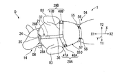
- FIG. 1 and FIG.2 the vest 1 for dogs of this embodiment is used attaching to the back part D1 of the dog D.
- FIG. The dog D is preferably a disaster rescue dog that has received certain training.
- the dog D is a large dog having a weight of about 30 kg
- the dog D is a golden retriever, a German shepherd dog, or the like.
- the weight (mass) of the dog vest 1 is preferably about 10% of the weight of the dog D.
- the weight of the dog vest 1 for large dogs is about 3 kg
- the weight of the dog vest 1 for medium-sized dogs is about 1.3 kg.
- the dog vest 1 of this embodiment includes a base material 11, a support plate 12 attached to the first main surface 11 a of the base material 11, and the base material 11 in the support plate 12.
- a pair of sponges (elastic members) 13 that are attached to the outer surface 12a opposite to the above, and an attachment / detachment part 14 that attaches the base material 11 to the back part D1 of the dog D in a detachable manner.
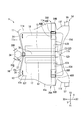
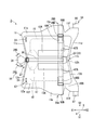
- FIG. 3 is a view of the dog vest 1 spreading flat in the thickness direction of the base material 11 and the support plate 12.
- the base material 11 is formed in a sheet shape with cloth, for example.
- a relatively strong fabric such as a fabric with an adhesive core attached to the fabric, a fabric laminated on the fabric, or a fabric coated with vinyl on the fabric may be used as the base material 11.
- a mesh layer may be provided on the base material 11.
- the base material 11 has a rectangular shape when viewed in the thickness direction of the base material 11.
- cloth housing parts 17 and 18 are attached to the second main surface 11 b of the base material 11. More specifically, the accommodating portion 17 is attached to the right side Y1 with respect to the central portion 11h of the base material 11 in the left-right direction Y.
- the left-right direction Y is a direction including the right side Y1 and the left side Y2, and is a parallel direction in which the pair of sponges 13 are arranged.
- the right side Y1 is the first side in the left-right direction Y
- the left side Y2 is the second side in the left-right direction Y.
- the front-rear direction X is a direction including the front X1 and the rear X2, and is a direction orthogonal (crossing) to the left-right direction Y.
- the front-rear direction X and the left-right direction Y are directions along the outer surface 12a of the support plate 12 that is flat in a natural state to be described later.
- These front X1, rear X2, right Y1, and left Y2 are directions based on the dog D to which the dog vest 1 is attached.
- the accommodating portion 18 is attached to the left side Y2 with respect to the central portion 11h of the base material 11.
- the accommodating parts 17 and 18 are formed in a bag shape.
- the accommodating parts 17 and 18 are attached to the base material 11 so as to be symmetrical in the left-right direction Y across the central part 11 h of the base material 11.
- the housing portions 17 and 18 are preferably arranged within the range of the outer edge 12 f of the support plate 12 in the base 11 when viewed in the thickness direction of the support plate 12.
- the range of the outer edge 12f of the support plate 12 mentioned here means that it may be inside the outer edge 12f or on the outer edge 12f when viewed in the thickness direction.
- a known wire fastener 18 a is attached to the accommodating portion 18.
- the user can accommodate the devices E1 and E2 such as a battery in the housing portion 18 through the wire fastener 18a.
- the devices E3 and E4 can be accommodated in the accommodating portion 17.
- the internal volumes of the accommodating portions 17 and 18 are made substantially equal, and the total weight of the devices E3 and E4 accommodated in the accommodating portion 17 and the total weight of the devices E1 and E2 accommodated in the accommodating portion 18 are substantially equal. It is preferable to do. By doing in this way, when the dog vest 1 is attached to the back D1 of the dog D, the dog vest 1 is less likely to be displaced in the left-right direction Y with respect to the back D1 of the dog D.
- a bag-like holding member 19 having an opening at the front X1 and the rear X2 is attached to the base 11 at the base of the front leg D3 of the dog D.
- a first surface fastener (engagement portion) 22 is disposed in the central portion 11 h in the left-right direction Y of the first main surface 11 a of the base material 11.
- the first hook-and-loop fastener 22 is provided with many J-shaped hooks (not shown).
- the first surface fastener 22 is fixed to the end portion of the rear X2 of the base material 11 with an adhesive, a suture thread or the like.
- the support plate 12 is formed of a light, thin, and soft (flexible) plate material. Specifically, the support plate 12 is formed of a resin plate material such as polypropylene, vinyl chloride, polycarbonate, or nylon. The support plate 12 has, for example, a flat plate shape that is rectangular when viewed in the thickness direction in a natural state where no external force is applied. The support plate 12 can be curved along the back D1 of the dog D by applying an external force.
- the support plate 12 may be formed of a carbon material obtained by plain weaving of fibrous carbon.
- the thickness of the support plate 12 is preferably 0.5 mm or greater and 1.0 mm or less, and more preferably 0.75 mm.
- the flexural strength based on the ASTM (American Society for Test Material) D790 specification of the support plate 12 is 100 kgf / cm 2 or more and 800 kgf / cm 2 or less (1 kgf / cm 2 is 98.1 kPa (kilopascal)). It is preferably about .81 MPa or more and 78.5 MPa or less.
- the Japanese Industrial Standard corresponding to ASTM D790 is JIS K 7074: 1988, which is a bending test method for carbon fiber reinforced plastics.
- Concave portions 12c and 12d corresponding to the concave portions 11c and 11d of the base material 11 are formed on the sides of the support plate 12 which are the front X1 and the rear X2. That is, when viewed in the vertical direction, the concave portion 12 c of the support plate 12 is disposed so as to overlap the concave portion 11 c of the base material 11. The recess 12 d of the support plate 12 is disposed so as to overlap the recess 11 d of the base material 11.
- the support plate 12 is disposed on the back D1 of the dog D in a curved state along the back D1. Since the recess 11c is formed in the base 11 and the recess 12c is formed in the support plate 12, when the dog vest 1 is attached to the back D1 of the dog D, the dog D moves the head without any trouble. Can do. Further, since the concave portion 11d is formed in the base material 11 and the concave portion 12d is formed in the support plate 12, the dog D warps the back portion D1 when the dog vest 1 is attached to the back portion D1 of the dog D. It becomes easy to bend.
- a second surface fastener (engaged portion) 23 is disposed at the center portion 12h in the left-right direction Y of the outer surface of the support plate 12 opposite to the outer surface 12a.
- the 1st surface fastener 22 and the 2nd surface fastener 23 comprise a surface fastener.
- the second hook-and-loop fastener 23 is provided with a number of U-shaped loops (not shown).
- the second surface fastener 23 is fixed to the rear X2 end of the support plate 12 with an adhesive or the like.
- the second hook-and-loop fastener 23 is detachably attached to the first hook-and-loop fastener 22 by engaging the loop of the second hook-and-loop fastener 23 with the hook of the first hook-and-loop fastener 22 or releasing the engagement.
- the end X2 of the base 11 and the end X2 of the support plate 12 are in the center portions 11h and 12h in the left-right direction Y of the base 11 and the support plate 12, respectively. Is detachable.
- the front X1 end of the base 11 and the front X1 end of the support plate 12 are fixed by a pair of fixing members 24 such as sutures.
- the pair of fixing members 24 fix the end portion on the right side Y1 of the base material 11 and the end portion on the right side Y1 of the support plate 12, and the end portion on the left side Y2 of the base material 11 and the left side of the support plate 12.
- the end of the direction Y2 is fixed.
- members such as hook-and-loop fastener 22,23, instead of a pair of fixing member 24.
- FIG. instead of the hook-and-loop fasteners 22 and 23, the base X 11 and the rear X2 ends of the support plate 12 may be fixed with sutures or the like.
- each sponge 13 has a rectangular parallelepiped shape.
- the pair of sponges 13 are attached to the support plate 12 with sutures, an adhesive, or the like in a state where they are arranged with a space in the left-right direction Y.
- the pair of sponges 13 extends in the front-rear direction X.
- the thickness of each sponge 13 is preferably 5 mm or more and 40 mm or less, more preferably 10 mm or more and 30 mm or less, and particularly preferably 20 mm.
- Each sponge 13 has a compressive stress at 25% strain based on JIS K 6767: 1999, foamed plastic-polyethylene test method, preferably 1 kPa (kilopascal) to 50 kPa, more preferably 2 kPa to 10 kPa. .
- the aforementioned compressive stress may be 130 kPa. It is preferable to change the thickness of each sponge 13 according to the compressive stress of the sponge 13. As shown in FIG. 4, the distance between the pair of sponges 13 (the distance along the outer surface 12a of the support plate 12) is preferably about the diameter of the spine D6 of the dog D to which the dog vest 1 is attached. For example, this distance is 30 mm.
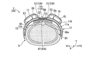
- the pair of sponges 13 sandwiches the spine D6 of the dog D between the pair of sponges 13, and the back D1 of the dog D It arrange
- the detachable part 14 is not particularly limited as long as the base material 11 can be detachably attached to the back part D1 of the dog D.
- the attachment / detachment part 14 is the 1st length which connects the base material 11 and the connection tool 27 which are arrange
- the configurations of the first length adjusting mechanism 28A and the second length adjusting mechanism 28B are the same.
- the configuration of the first length adjusting mechanism 28A is shown by adding an uppercase letter “A” to the number.
- a configuration corresponding to the first length adjusting mechanism 28A in the second length adjusting mechanism 28B is indicated by adding an uppercase letter “B” to the same numeral as the first length adjusting mechanism 28A.
- the overlapping description is omitted.
- the first belt piece 40A of the first length adjustment mechanism 28A and the first belt piece 40B of the second length adjustment mechanism 28B have the same configuration. The same applies to the first length adjustment mechanism 29A and the second length adjustment mechanism 29B.
- the connecting tool 27 includes, for example, a connecting member 34, a belt feed buckle 35 fixed to the connecting member 34, and a central belt 36 extending from the belt feed buckle 35 to the rear X2.
- the connecting member 34 is formed in a hexagonal plate shape with metal, resin, or the like.
- the belt feed buckle 35 is formed in a ring shape from metal, resin, or the like.
- the central belt 36 is held by a belt feeding buckle 35.
- the end portion of the front belt X1 of the central belt 36 can be attached to and detached from the central portion in the longitudinal direction of the central belt 36 by a hook-and-loop fastener 37. Since the end portion of the front belt X1 of the central belt 36 is attached by the hook-and-loop fastener 37, the end portion of the central belt 36 is unlikely to obstruct the movement of the dog D.
- the first length adjusting mechanism 28A and the second length adjusting mechanism 28B are used by being attached around the neck D8 of the dog D.
- the first length adjusting mechanism 28A includes a first belt piece 40A extending from the connecting member 34 to the right Y1, an insertion buckle 41A fixed to the end of the first belt piece 40A, and a right side Y1 of the insertion buckle 41A. It has a fixed belt feed buckle 42A and a second belt piece 43A having a first end held by the belt feed buckle 42A.
- the insertion buckle 41A has a known configuration, and has a convex member and a concave member (not shown) that are detachable from each other. For example, the concave member is fixed to the end of the first belt piece 40A, and the convex member is fixed to the belt feed buckle 42A.
- the user attaches the convex member and the concave member to make the insertion buckle 41A in a connected state, or separates the convex member and the concave member to make the insertion buckle 41A in a separated state.
- 40A and the second belt piece 43A can be connected, or this connection can be released.
- the second end of the second belt piece 43A is sewn to the base material 11.
- the second length adjustment mechanism 28B is configured in the same manner as the first length adjustment mechanism 28A, and includes a first belt piece 40B, an insertion buckle 41B, a belt feed buckle 42B, and a second belt piece 43B. ing. As shown in FIG. 1, the 1st end part of the 2nd belt piece 43B can be attached or detached to the base material 11 by the hook-and-loop fastener 44B.
- the first length adjusting mechanism 29 ⁇ / b> A and the second length adjusting mechanism 29 ⁇ / b> B are used by being attached around the front X ⁇ b> 1 portion of the torso D ⁇ b> 10 of the dog D.
- the second length adjustment mechanism 29B is configured in the same manner as the first length adjustment mechanism 28A.
- the second length adjusting mechanism 29B includes a first belt piece 47B extending from the rear X2 end of the central belt 36 to the left Y2, an insertion buckle 48B fixed to the end of the first belt piece 47B, and an insertion buckle.
- a belt feed buckle 49B fixed to 48B and a second belt piece 50B having a first end portion held by the belt feed buckle 49B are provided.
- the second end of the second belt piece 50B is sewn to the flap 11e of the base material 11.
- the overall length of the second length adjusting mechanism 29B is adjusted.
- the first end of the second belt piece 50B can be attached to and detached from the base material 11 with a hook-and-loop fastener 51B.
- the detachable portion 14 has a third length adjusting mechanism 54 attached to the pair of flaps 11 f of the base material 11.
- the third length adjusting mechanism 54 is sewn to the first belt piece 55 sewn on the left Y2 flap 11f, the insertion buckle 56 fixed to the first belt piece 55, and the right Y1 flap 11f.
- a belt feed buckle 58 that holds the second belt piece 57.
- the end of the first belt piece 55 is fixed to a concave member of the insertion buckle 56, for example.
- the second belt piece 57 is folded at the center in the longitudinal direction, and the folded portion is locked to the convex member of the insertion buckle 56. A portion where the second belt piece 57 is folded and overlapped is held by the belt feeding buckle 58.
- the overall length of the third length adjusting mechanism 54 is adjusted.
- FIG. 4 Various devices are mounted on the vest 1 for dogs configured as described above. Specifically, as shown in FIG. 1, the camera E ⁇ b> 6 is held in the holding member 19, and the antenna E ⁇ b> 7 for the wireless transmission device is attached to the front X ⁇ b> 1 of the base material 11.
- Devices E1 to E4 shown in FIG. 4 include a battery, an image processing board, a wireless transmission device, and the like. The devices E1 to E4 may be formed of a relatively hard material such as metal or plastic, or may have corners. Each device is connected by a cable with a symbol omitted.
- the user puts the insertion buckles 41A, 41B, 48A, 48B, 56 of the attaching / detaching portion 14 into a separated state as appropriate, or lengthens the length adjusting mechanisms 28A, 28B, 29A, 29B.
- the user passes the neck D8 of the dog D between the base material 11 and the length adjusting mechanisms 28A and 28B. If necessary, the insertion buckles 41A and 41B are connected.
- the first end portions of the second belt pieces 43 ⁇ / b> A and 43 ⁇ / b> B are gripped by the left and right hands, and these first end portions are pulled away from the connecting member 34 of the connecting device 27.
- the length adjustment mechanisms 28A, 28B are shortened equally to the left and right, and the length adjustment mechanisms 28A, 28B are attached to the neck D8.
- the front legs D3 are passed between the length adjusting mechanisms 29A, 29B and the central belt 36.
- a pair of sponges 13 are arranged so as to contact the back D1 of the dog D.
- each sponge 13 extends in the front-rear direction X and is arranged so that the spine D ⁇ b> 6 of the dog D is sandwiched between the pair of sponges 13.
- a sponge 13 extending in the front-rear direction X is attached along the spine D6 of the dog D. If necessary, the insertion buckles 48A and 48B are connected.
- the first end portions of the second belt pieces 50 ⁇ / b> A and 50 ⁇ / b> B are gripped by the left and right hands, and these first end portions are pulled away from the central belt 36 of the connector 27.
- the length adjustment mechanisms 29A, 29B are shortened equally to the left and right, and the length adjustment mechanisms 29A, 29B are attached to the front X1 portion of the body D10.
- the belt pieces 55 and 57 of the third length adjusting mechanism 54 are wound around the rear X2 portion of the body D10, and the insertion buckle 56 is brought into a connected state.
- the length of the third length adjusting mechanism 54 is shortened.
- the third length adjusting mechanism 54 is attached to the rear X2 portion of the body D10.
- the dog vest 1 is attached to the back part D1 of the dog D through the base material 11 by the attaching / detaching part 14 in the above procedure.
- the pair of sponges 13 are compressed in the thickness direction.
- the base member 11 is attached to the back D1 of the dog D by the attaching / detaching unit 14.
- the dog vest 1 tries to move in the left-right direction Y in which the pair of sponges 13 are arranged with respect to the spine D6 of the dog D
- the pair of sponges 13 are locked to the spine D6 of the dog D.
- the sponge 13 extending in the front-rear direction X is attached along the spine D6 of the dog D, the sponge 13 is difficult to be inclined with respect to the spine D6 of the dog D.
- the accommodating portions 17 and 18 are disposed within the range of the outer edge 12 f of the support plate 12 in the base material 11. As a result, the devices E1 to E4 accommodated in the accommodating portions 17 and 18 come into contact with the back D1 of the dog D via the support plate 12 that is harder than the cloth accommodating portions 17 and 18 and the base material 11.
- the user places the insertion buckles 41A, 41B, 48A, 48B, 56 in a separated state.
- the length adjusting mechanisms 28A and 28B are removed from the neck D8.
- the length adjusting mechanisms 29A, 29B, 54 are removed from the body D10.
- the dog vest 1 is removed from the back D1 of the dog D by the above procedure.
- the base material 11 is attached to the back D1 of the dog D by the attaching / detaching unit 14 with the pair of sponges 13 sandwiching the spine D6 of the dog D.
- the pair of sponges 13 are locked to the spine D6 of the dog D. Since the direction in which the pair of sponges 13 are arranged is the left-right direction Y of the dog D, the dog vest 1 attached to the dog D can be prevented from shifting in the left-right direction Y around the torso D10 of the dog D.
- the device mounted on the dog vest when the device mounted on the dog vest is relatively hard, the device may hit the back when the dog vest is attached to the back of the disaster rescue dog, and the disaster rescue dog may feel uncomfortable There is.
- the accommodating parts 17 and 18 are arrange
- the stress acting on the back D1 of the dog D is dispersed, and the dog D feels when the dog vest 1 is attached.
- a sense of incongruity can be reduced.
- the back D1 of the dog D is less likely to be pressed and the positions of the devices E1 to E4 can be prevented from changing. If the position of a device such as a sensor changes, not only the movement of the dog D is disturbed, but also noise appears in the data from the sensor.
- the center part 11h of the base material 11 and the support plate 12 in the left-right direction Y is connected to each other by the hook-and-loop fasteners 22, 23, the end portions of the base material 11 and the support plate 12 in the left-right direction Y are connected.
- the center portion 12 h of the support plate 12 can be prevented from shifting in the left-right direction Y with respect to the center portion 11 h of the base material 11.
- the accommodating parts 17 and 18 are attached to the base material 11 so as to be symmetrical in the left-right direction Y across the central part 11 h of the base material 11. Therefore, the dog vest 1 can be made difficult to shift in the left-right direction Y due to the own weight of the devices E1 to E4 accommodated in the accommodating portions 17 and 18.
- Each sponge 13 extends in the front-rear direction X, and a pair of sponges 13 are attached along the spine D6 of the dog D. Thereby, it can suppress that a pair of sponge 13 becomes diagonal with respect to the spine D6 of the dog D.
- FIG. Since the elastic member is the sponge 13, when the dog vest 1 is attached to the back D1 of the dog D, the pair of sponges 13 are reliably compressed, and the sponge 13 can be reliably deformed following the shape of the spine D6.
- the attachment / detachment portion 14 includes the connector 27, the first length adjustment mechanism 28A, and the second length adjustment mechanism 28B, the attachment / detachment portion 14 can be equally tightened to the back portion D1 of the dog D.
- FIG. 8 is a view corresponding to FIG. 3 of the dog vest according to the first embodiment, and is a bottom view in which a part of the main part of the dog vest is broken.
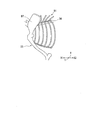
- FIG. 9 is a side view showing a part of the skeleton of the first half of the dog.
- symbol same as 1st Embodiment is attached
- FIG. 8 is a view of the dog vest 3 spreading flat in the thickness direction of the base material 11 and the support plate 12.
- the dog vest 3 of the present embodiment is formed so that the sponge (elastic member) 13A avoids the portion corresponding to the position where the shoulder blade D7 is disposed in the back D1 of the dog D.
- This is different from the dog vest 1 of the first embodiment.
- the dog vest is worn when the sponge is placed on the scapula D7. The scapula D7 pushes up the sponge.
- the back part D1 except the vicinity of the scapula D7 and the sponge do not sufficiently contact.
- the dog vest may be displaced from the predetermined position on the back D1 in the left-right direction Y due to the movement of the scapula D7.
- the scapula avoiding portion 15 where the sponge 13 ⁇ / b> A is not disposed is formed on the front X ⁇ b> 1 on the head side of the dog D. That is, the sponge 13A is formed so as to avoid a position where the scapula D7 of the back portion D1 is disposed.
- the pair of sponges 13A preferably surrounds the thoracic vertebra that is a part of the spine D6 and is disposed so as to press the thoracic vertebra from above. Accordingly, even when the dog D having a skeleton whose shape of the scapula D7 is raised on the body surface is walking and the scapula D7 is moving, the sponge 13A and the back D1 can be sufficiently brought into contact with each other.
- the dog vest 3 can be reliably prevented from shifting in the left-right direction Y.
- a pair of sponges 13A may be connected by a connecting material 66 formed of sponge, as in a dog vest 3A shown in FIG.
- the connecting member 66 has a recess 66a corresponding to the spine D6 of the dog D.
- the pair of sponges 13A and the connecting material 66 constitute a second elastic member 67A.
- the second elastic member 67A comes into contact with the back D1 of the dog D while the spine D6 of the dog D enters the recess 66a. Therefore, the second elastic member 67A is locked in the left-right direction Y with respect to the spine D6 of the dog D, and when the dog vest 3A is attached to the back D1 of the dog D, the dog vest 3A is moved in the left-right direction Y. Shifting can be suppressed.
- a plurality of sponges 13A may be provided in the front-rear direction X.
- the length of each sponge 13A in the front-rear direction X may be short.
- the elastic member is the sponge 13A, the elastic member can be made of urethane foam or the like in addition to the sponge 13A.
- the scapula avoiding portion 15 is formed by removing the front portion of the sponge 13 to become the sponge 13A, but the configuration of the scapula avoiding portion is not limited to this.
- the scapula avoiding portion 15 may be formed by reducing the thickness of the front portion of the sponge 13 or forming a recess along the shape of the scapula D7. That is, the configuration of the scapula avoiding portion 15 is not limited as long as the sponge is configured not to interfere with the scapula D7.
- the dog vest having the same configuration as that of the second embodiment was worn on a standard poodle, and the ease of slippage of the dog vest and the degree of stress of the dog were verified.
- the standard poodle is a dog breed having a skeleton in which the shape of the scapula is raised on the body surface as described above.
- the standard poodle wearing the dog vest had a distance of 8 cm from the base of the neck to the scapula. Therefore, the scapula avoiding portion was configured by not forming an elastic member up to 10 cm from the front end of the base material. A sponge was used as the elastic member.
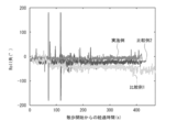
- FIG. 10 shows the change over time of the inclination of the dog vest with respect to the back of the dog when strolling the standard poodle wearing the dog vest according to this embodiment.
- An inertial measurement device IMU was used for measurement of the tilt (Roll angle).
- Comparative Example 1 is a vest for dogs in which a sponge is formed up to the front end of the base material and does not have a scapula avoidance part.
- Comparative Example 2 is a dog vest that does not have a sponge itself.
- Comparative Example 1 since the dog is a standard poodle, a dog vest that does not have a scapula avoidance portion is referred to as Comparative Example 1 for convenience.
- the dog vest of Comparative Example 1 is the dog vest of the example.
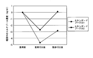
- the cortisol concentrations of two standard poodles wearing the vest for dogs according to this example having the configuration of the second embodiment were measured.
- the measurement was performed by collecting three conditions of saliva after the dog vest was worn before the dog vest was worn, and after walking while wearing the dog vest. In general, it is said that it takes about 10 minutes from when a dog feels stress until it is reflected in the salivary cortisol concentration. Therefore, after waiting for 15 minutes in each state, saliva was collected.
- the measurement results are shown in FIG.
- concentration of the saliva before putting on the vest for dogs is shown.
- the amount of change after wearing the dog vest according to this example and after taking a walk was -3 to 5 ng / ml (nanogram per milliliter) for both standard poodles.
- the amount of change in this range is judged to be very small, and it can be considered that neither standard poodle feels the stress due to wearing the dog vest according to this embodiment.
- FIG. 12 is a view corresponding to FIG. 3 of the dog vest according to the first embodiment, and is a bottom view in which a part of the main part of the dog vest according to the third embodiment is broken.
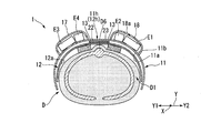
- FIG. 13 is a cross-sectional view as seen from the front of the dog vest attached to the dog.
- symbol same as 1st Embodiment is attached
- the vest 4 for dogs of this embodiment has the base material 11 and the support plate 12 shortened in the left-right direction Y with respect to the dog vest 1 which concerns on 1st Embodiment. Is different.
- the distance L1 in the left-right direction Y between the pair of sponges 13 along the outer surface 12a of the support plate 12 is not less than 100 mm and not more than 140 mm.
- the distance L1 is more preferably 100 mm or more and 120 mm or less.
- the dog vest 4 configured as described above is used by being attached to a so-called slender dog D16 (hereinafter simply referred to as a dog D16) shown in FIG.
- the dog D16 means a dog whose whole body is thin, such as the torso D10.
- the dog D16 is a thin labrador, a standard poodle or the like.
- Such a dog D16 is, for example, in the left-right direction Y of the torso D10 with respect to the length in the up-down direction of the torso D10 in a quadrilateral posture in which both hands and both feet are put on the ground or floor with respect to the dog D
- the ratio of the lengths becomes shorter. That is, the trunk
- the pair of sponges 13 sandwich the entire back portion D1 of the dog D16 in the left-right direction Y between the pair of sponges 13, as shown in FIG.
- Each sponge 13 is arranged at the end in the left-right direction Y of the back D1 of the dog D16.
- the pair of sponges 13 sandwich the middle part in the vertical direction of the body D10 of the dog D16 in the left-right direction Y.
- the pair of sponges 13 sandwich the vertical middle portion of the rib D12 of the dog D16 in the left-right direction Y.
- the pair of sponges 13 does not sandwich only the spine D6 of the dog D16 between the pair of sponges 13, but the entire back portion D1 of the dog D16, which is a wider range, between the pair of sponges 13 in the left-right direction Y. Pinch.
- the surface of the sponge 13 that contacts the back part D1 of the dog D faces downward (see FIG. 4).
- the surface of each sponge 13 that contacts the back D1 of the dog D16 faces downward and inward in the left-right direction Y and faces obliquely downward.
- the surface of the sponge 13 that contacts the back D1 of the dog D16 applies a force F in a direction substantially perpendicular to the outer surface of the contacting back D1.
- the force F is divided into a component force F1 along the vertical direction and a component force F2 along the left-right direction Y.
- the entire back portion D1 of the dog D16 can be reliably sandwiched between the pair of sponges 13 in the left-right direction Y. It is possible to suppress the shift in the left-right direction Y when the vest 4 is attached.
- the dog vest of the present invention can be used as a vest for mounting a device on the back of the dog while suppressing the burden on the dog.
Landscapes
- Life Sciences & Earth Sciences (AREA)
- Environmental Sciences (AREA)
- Zoology (AREA)
- Animal Husbandry (AREA)
- Biodiversity & Conservation Biology (AREA)
- Health & Medical Sciences (AREA)
- General Health & Medical Sciences (AREA)
- Physical Education & Sports Medicine (AREA)
- Animal Behavior & Ethology (AREA)
- Professional, Industrial, Or Sporting Protective Garments (AREA)
Abstract
犬用ベスト(1)は、基材(11)と、可撓性を有し、基材の第一の主面(11a)に取付けられるとともに犬(D)の背部(D1)上に配置される支持板(12)と、支持板(12)における基材とは反対の外面(12a)に、互いに間隔を空けて並べて取付けられる一対の弾性部材(13)と、基材(11)を犬(D)の背部(D1)に着脱可能に取付ける着脱部と、を備え、一対の弾性部材(13)は、一対の弾性部材(13)の間に犬(D)の背骨(D6)を挟んで、犬(D)の背部(D1)に接触するように配置される。
Description
本発明は、犬用ベストに関する。
本願は、2016年6月20日に、日本に出願された日本国特願2016-121692号に基づき優先権を主張し、その内容をここに援用する。
本願は、2016年6月20日に、日本に出願された日本国特願2016-121692号に基づき優先権を主張し、その内容をここに援用する。
従来、広範囲にわたる被災地に点在する被災者を迅速に発見するために、災害救助犬(犬)を導入する方法が検討されている。
災害救助犬を導入するためには、災害救助犬の探査の記録と、探査の信頼性を判断する方法と、が必要不可欠である。
災害救助犬を導入するためには、災害救助犬の探査の記録と、探査の信頼性を判断する方法と、が必要不可欠である。
例えば非特許文献1のように、災害救助犬の背部に犬用ベストを取付け、この犬用ベストにカメラや、カメラで取得した画像を送信するための無線送信装置等の機器を搭載することが検討されている。災害救助犬が見た被災地の画像は、災害救助犬に指示を与えるハンドラーが所持する携帯型コンピュータ等に送信され、記録される。ハンドラーは、送信された画像を確認し、必要に応じて災害救助犬に指示を与える。
坂口、大野、外2名、「災害救助犬の動作計測」、No.12-3 Proceedings of the 2012 JSME Conference on Robotics and Mechatronics, Hamamatsu, Japan, May 27-29, 2012
しかしながら、犬の皮膚に生えている体毛により、背部に対して犬用ベストが滑りやすい。背部に対して犬用ベストが犬の胴体周りに犬の左右方向にずれると、犬用ベストには元の位置に戻る復元力が作用しないため、災害救助犬に負担がかかる。
本発明は、このような問題点に鑑みてなされたものであって、犬の背部に取付けたときに左右方向にずれるのを抑制した犬用ベストを提供することを目的とする。
上記課題を解決するために、この発明は以下の手段を提案している。
本発明の第一態様にかかる犬用ベストは、基材と、可撓性を有し、前記基材の第一の主面に取付けられるとともに犬の背部上に配置されるように構成される支持板と、前記支持板における前記基材とは反対の外面に、互いに間隔を空けて並べて取付けられる一対の弾性部材と、前記基材を前記犬の背部に着脱可能に取付ける着脱部と、を備え、前記一対の弾性部材は、前記一対の弾性部材の間に前記犬の背骨を挟んで、前記犬の背部に接触するように構成される。
本発明の第一態様にかかる犬用ベストは、基材と、可撓性を有し、前記基材の第一の主面に取付けられるとともに犬の背部上に配置されるように構成される支持板と、前記支持板における前記基材とは反対の外面に、互いに間隔を空けて並べて取付けられる一対の弾性部材と、前記基材を前記犬の背部に着脱可能に取付ける着脱部と、を備え、前記一対の弾性部材は、前記一対の弾性部材の間に前記犬の背骨を挟んで、前記犬の背部に接触するように構成される。
上記態様にかかる犬用ベストにおいて、前記基材の第二の主面に取付けられた布製の収容部を備え、前記基材は布製であり、前記収容部は、前記支持板の厚さ方向に見たときに、前記基材における前記支持板の外縁の範囲内に配置されてもよい。
上記態様にかかる犬用ベストにおいて、前記基材の前記第一の主面における前記一対の弾性部材の並列方向の中央部に配置された係合部と、前記支持板における前記並列方向の中央部に配置され、前記係合部に着脱可能に取付けられる被係合部と、を備えてもよい。
上記態様にかかる犬用ベストにおいて、前記基材の前記第一の主面における前記一対の弾性部材の並列方向の中央部に配置された係合部と、前記支持板における前記並列方向の中央部に配置され、前記係合部に着脱可能に取付けられる被係合部と、を備えてもよい。
前記一対の弾性部材は、前記一対の弾性部材の並列方向に交差する方向であって、前記基材の前記外面に沿う方向に延びてもよい。
前記支持板の、ASTM D790の規定に基づいた曲げ強さは、9.81MPa以上78.5MPa以下であってもよい。
前記支持板の、ASTM D790の規定に基づいた曲げ強さは、9.81MPa以上78.5MPa以下であってもよい。
前記弾性部材の、JIS K 6767の規定に基づいた25%ひずみ時の圧縮応力は、1kPa以上50kPa以下であってもよい。
前記弾性部材は、スポンジであってもよい。
前記弾性部材は、スポンジであってもよい。
前記一対の弾性部材は、前記犬の肩甲骨と干渉しないように構成されてもよい。
本発明の第二態様にかかる犬用ベストは、基材と、可撓性を有し、前記基材の第一の主面に取付けられるとともに犬の背部上に配置されるように構成される支持板と、凹部が形成され、前記支持板における前記基材とは反対の外面に取付けられる第二弾性部材と、前記基材を前記犬の背部に着脱可能に取付ける着脱部と、を備え、前記第二弾性部材は、前記第二弾性部材の前記凹部内に前記犬の背骨が入るとともに、前記犬の背部に接触するように構成される。
前記第二弾性部材は、前記犬の肩甲骨と干渉しないように構成されてもよい。
本発明の第三態様にかかる犬用ベストは、基材と、可撓性を有し、前記基材の第一の主面に取付けられるとともに犬の背部上に配置されるように構成される支持板と、前記支持板における前記基材とは反対の外面に、互いに間隔を空けて並べて取付けられる一対の弾性部材と、前記基材を前記犬の背部に着脱可能に取付ける着脱部と、を備え、前記一対の弾性部材は、前記一対の弾性部材の間に前記犬の背部を左右方向に挟むように構成される。
前記一対の弾性部材の間の、前記支持板の前記外面に沿った前記一対の弾性部材の並列方向の距離は、100mm以上140mm以下である。
本発明の上記態様に係る犬用ベストによれば、犬の背部に取付けたときに左右方向にずれるのを抑制することができる。
[第1実施形態]
以下、本発明の第1実施形態に係る犬用ベストを、図1から図7を参照しながら説明する。
図1及び図2に示すように、本実施形態の犬用ベスト1は、犬Dの背部D1に取付けて用いられる。犬Dは、一定の訓練を受けた災害救助犬であることが好ましい。犬Dは、例えば、体重が30kg程度の大型犬であれば、ゴールデン・レトリバー、ジャーマン・シェパード・ドッグ等である。体重が15kg程度の中型犬であれば、ブリタニー・スパニエル、スタンダードプードル等である。体重が8kg程度の小型犬であれば、ジャック・ラッセル・テリア等である。
なお、犬用ベスト1の重量(質量)は、犬Dの体重の10%程度であることが好ましい。例えば、大型犬用の犬用ベスト1の重量は3kg程度であり、中型犬用の犬用ベスト1の重量は1.3kg程度である。
図3及び図4に示すように、本実施形態の犬用ベスト1は、基材11と、基材11の第一の主面11aに取付けられる支持板12と、支持板12における基材11とは反対の外面12aに取付けられる一対のスポンジ(弾性部材)13と、基材11を犬Dの背部D1に着脱可能に取付ける着脱部14と、を備えている。
なお、図3は、平坦に広がった犬用ベスト1を、基材11及び支持板12の厚さ方向に見た図である。
なお、図3は、平坦に広がった犬用ベスト1を、基材11及び支持板12の厚さ方向に見た図である。
基材11は、例えば布でシート状に形成されている。基材11に、布に接着芯を付けた生地、布にラミネートした生地、布にビニールコーティングをした生地等、比較的丈夫な生地を用いてもよい。基材11の通気性を向上させるために、基材11にメッシュ層を設けてもよい。
図3に示すように、基材11は、基材11の厚さ方向に見たときに、矩形状である。犬用ベスト1が犬Dに取付けられたときに、基材11において犬Dの前方X1、及び後方X2となる辺には、凹部11c、11dが形成されている。犬用ベスト1が犬Dに取付けられたときに、基材11において犬Dの右方Y1、及び左方Y2となる辺には、後述する長さ調節機構29A、29B、54を取付けやすくするためのフラップ11e、11fが形成されている。フラップ11eは、フラップ11fよりも前方X1に形成されている。
図3に示すように、基材11は、基材11の厚さ方向に見たときに、矩形状である。犬用ベスト1が犬Dに取付けられたときに、基材11において犬Dの前方X1、及び後方X2となる辺には、凹部11c、11dが形成されている。犬用ベスト1が犬Dに取付けられたときに、基材11において犬Dの右方Y1、及び左方Y2となる辺には、後述する長さ調節機構29A、29B、54を取付けやすくするためのフラップ11e、11fが形成されている。フラップ11eは、フラップ11fよりも前方X1に形成されている。
図1及び図4に示すように、基材11の第二の主面11bには、布製の収容部17、18が取付けられている。より詳しくは、収容部17は、基材11の左右方向Yの中央部11hよりも右方Y1に取付けられている。なお、この左右方向Yは、右方Y1及び左方Y2を含む方向であり、一対のスポンジ13が並ぶ並列方向となる。例えば、右方Y1が左右方向Yの第一方となり、左方Y2が左右方向Yの第二方となる。
前後方向Xは、前方X1及び後方X2を含む方向であり、左右方向Yに直交(交差)する方向となる。これら前後方向X及び左右方向Yは、後述する自然状態で平板状となった支持板12の外面12aに沿う方向である。これら前方X1、後方X2、右方Y1、及び左方Y2は、犬用ベスト1が取付けられた犬Dを基準とした方向である。
収容部18は、基材11の中央部11hよりも左方Y2に取付けられている。収容部17、18は、袋状に形成されている。収容部17、18は、基材11の中央部11hを挟んで左右方向Yに対称となるように基材11に取付けられている。
図3に示すように、収容部17、18は、支持板12の厚さ方向に見たときに、基材11における支持板12の外縁12fの範囲内に配置されていることが好ましい。ここで言う支持板12の外縁12fの範囲内は、厚さ方向に見たときに外縁12fの内部であってもよいし、外縁12f上にあってもよいことを意味する。
図1及び図4に示すように、収容部18には公知の線ファスナー18aが取付けられている。線ファスナー18aを開いた状態にすると、使用者は、線ファスナー18aを通して収容部18内にバッテリー等の機器E1、E2を収容することができる。同様に、収容部17内に機器E3、E4を収容することができる。
収容部17、18の内容積をほぼ等しくするとともに、収容部17内に収容される機器E3、E4の全重量と収容部18内に収容される機器E1、E2の全重量とを、ほぼ等しくすることが好ましい。このようにすることで、犬Dの背部D1に犬用ベスト1を取付けたときに、犬Dの背部D1に対して犬用ベスト1が左右方向Yにずれにくくなる。
収容部17、18の内容積をほぼ等しくするとともに、収容部17内に収容される機器E3、E4の全重量と収容部18内に収容される機器E1、E2の全重量とを、ほぼ等しくすることが好ましい。このようにすることで、犬Dの背部D1に犬用ベスト1を取付けたときに、犬Dの背部D1に対して犬用ベスト1が左右方向Yにずれにくくなる。
図1に示すように、基材11における犬Dの前脚D3の付け根の位置には、前方X1及び後方X2が開口した袋状の保持部材19が取付けられている。
図3及び図4に示すように、基材11の第一の主面11aにおける左右方向Yの中央部11hには、第一面ファスナー(係合部)22が配置されている。第一面ファスナー22には、図示はしないがJ字形のフックが多数設けられている。第一面ファスナー22は、基材11の後方X2の端部に接着剤や縫合糸等により固定されている。
図3及び図4に示すように、基材11の第一の主面11aにおける左右方向Yの中央部11hには、第一面ファスナー(係合部)22が配置されている。第一面ファスナー22には、図示はしないがJ字形のフックが多数設けられている。第一面ファスナー22は、基材11の後方X2の端部に接着剤や縫合糸等により固定されている。
支持板12は、軽く、薄く、柔軟な(可撓性を有する)板材で形成されている。具体的には、支持板12は、例えばポリプロピレン、塩化ビニル、ポリカーボネート、ナイロン等の樹脂製の板材で形成されている。支持板12は、例えば、外力が作用しない自然状態では、厚さ方向に見たときに矩形状となる平板状である。支持板12は、外力を作用させることで犬Dの背部D1に沿って湾曲させることが可能である。なお、支持板12は、繊維状のカーボンを平織り等にしたカーボン素材で形成してもよい。
支持板12の厚さは、0.5mm以上1.0mm以下であることが好ましく、0.75mmであることがより好ましい。支持板12のASTM(米国試験材料協会) D790の規定に基づいた曲げ強さは、100kgf/cm2以上800kgf/cm2以下(1kgf/cm2は98.1kPa(キロパスカル)であるため、9.81MPa以上78.5MPa以下)程度であることが好ましい。
なお、ASTM D790の規定に相当する日本工業規格は、JIS K 7074:1988、炭素繊維強化プラスチックの曲げ試験方法の規定である。
支持板12の厚さは、0.5mm以上1.0mm以下であることが好ましく、0.75mmであることがより好ましい。支持板12のASTM(米国試験材料協会) D790の規定に基づいた曲げ強さは、100kgf/cm2以上800kgf/cm2以下(1kgf/cm2は98.1kPa(キロパスカル)であるため、9.81MPa以上78.5MPa以下)程度であることが好ましい。
なお、ASTM D790の規定に相当する日本工業規格は、JIS K 7074:1988、炭素繊維強化プラスチックの曲げ試験方法の規定である。
支持板12の前方X1、及び後方X2となる辺には、基材11の凹部11c、11dに対応した凹部12c、12dが形成されている。すなわち、上下方向に見たときに、支持板12の凹部12cは、基材11の凹部11cに重なるように配置されている。支持板12の凹部12dは、基材11の凹部11dに重なるように配置されている。
支持板12は、犬Dの背部D1上に背部D1に沿って湾曲した状態に配置される。
基材11に凹部11cが形成され、支持板12に凹部12cが形成されていることで、犬Dの背部D1に犬用ベスト1を取付けたときに、犬Dが頭部を支障なく動かすことができる。また、基材11に凹部11dが形成され、支持板12に凹部12dが形成されていることで、犬Dの背部D1に犬用ベスト1を取付けたときに、犬Dが背部D1を反らすように曲げやすくなる。
基材11に凹部11cが形成され、支持板12に凹部12cが形成されていることで、犬Dの背部D1に犬用ベスト1を取付けたときに、犬Dが頭部を支障なく動かすことができる。また、基材11に凹部11dが形成され、支持板12に凹部12dが形成されていることで、犬Dの背部D1に犬用ベスト1を取付けたときに、犬Dが背部D1を反らすように曲げやすくなる。
支持板12における外面12aとは反対側の外面の左右方向Yの中央部12hには、第二面ファスナー(被係合部)23が配置されている。なお、第一面ファスナー22及び第二面ファスナー23は、面ファスナーを構成する。
第二面ファスナー23には、図示はしないがU字形のループが多数設けられている。第二面ファスナー23は、支持板12の後方X2の端部に接着剤等により固定されている。第二面ファスナー23のループが第一面ファスナー22のフックに係合したり、この係合が解除したりすることで、第二面ファスナー23は第一面ファスナー22に着脱可能に取付けられる。
このように、基材11の後方X2の端部と支持板12の後方X2の端部とは、基材11及び支持板12の左右方向Yの中央部11h、12hにおいて、面ファスナー22、23により着脱可能である。
第二面ファスナー23には、図示はしないがU字形のループが多数設けられている。第二面ファスナー23は、支持板12の後方X2の端部に接着剤等により固定されている。第二面ファスナー23のループが第一面ファスナー22のフックに係合したり、この係合が解除したりすることで、第二面ファスナー23は第一面ファスナー22に着脱可能に取付けられる。
このように、基材11の後方X2の端部と支持板12の後方X2の端部とは、基材11及び支持板12の左右方向Yの中央部11h、12hにおいて、面ファスナー22、23により着脱可能である。
本実施形態では、基材11の前方X1の端部と支持板12の前方X1の端部とは、縫合糸等の一対の固定部材24で固定されている。一対の固定部材24は、基材11の右方Y1の端部と支持板12の右方Y1の端部とを固定するとともに、基材11の左方Y2の端部と支持板12の左方Y2の端部とを固定する。
基材11の第一面ファスナー22から支持板12の第二面ファスナー23を取外すことで、使用者は、基材11に対して支持板12を一対の固定部材24周りに回転させることができる。
なお、基材11及び支持板12の前方X1の端部を、一対の固定部材24に代えて面ファスナー22、23等のような部材で着脱可能に取付けてもよい。面ファスナー22、23に代えて、基材11及び支持板12の後方X2の端部を縫合糸等で固定してもよい。
基材11の第一面ファスナー22から支持板12の第二面ファスナー23を取外すことで、使用者は、基材11に対して支持板12を一対の固定部材24周りに回転させることができる。
なお、基材11及び支持板12の前方X1の端部を、一対の固定部材24に代えて面ファスナー22、23等のような部材で着脱可能に取付けてもよい。面ファスナー22、23に代えて、基材11及び支持板12の後方X2の端部を縫合糸等で固定してもよい。
スポンジ13には、公知のゴムスポンジ等が用いられる。各スポンジ13は、直方体状である。一対のスポンジ13は、互いに左右方向Yに間隔を空けて並べた状態で、支持板12に縫合糸や接着剤等で取付けられている。
一対のスポンジ13は、前後方向Xに延びる。例えば、各スポンジ13の厚さは5mm以上40mm以下であることが好ましく、10mm以上30mm以下であることがより好ましく、20mmであることが特に好ましい。
各スポンジ13の、JIS K 6767:1999、発泡プラスチック-ポリエチレン-試験方法の規定に基づいた25%ひずみ時の圧縮応力は、1kPa(キロパスカル)以上50kPa以下が好ましく、2kPa以上10kPa以下がより好ましい。スポンジ13の左右方向Yの長さ及び厚さ、スポンジ13の気泡の組成等の内部構造によっては、前述の圧縮応力は、130kPaでもよい。
各スポンジ13の厚さは、スポンジ13の圧縮応力に応じて変えることが好ましい。
図4に示すように、一対のスポンジ13の間の距離(支持板12の外面12aに沿った距離)は、犬用ベスト1を取付ける犬Dの背骨D6の直径程度であることが好ましい。例えば、この距離は30mmである。
図4に示すように、犬Dの背部D1に犬用ベスト1を取付けたときに、一対のスポンジ13は、一対のスポンジ13の間に犬Dの背骨D6を挟んで、犬Dの背部D1に接触するように配置される。
着脱部14は、基材11を犬Dの背部D1に着脱可能に取付け可能であれば特に限定されない。本実施形態では、図2及び図5に示すように、着脱部14は、連結具27と、連結具27に対する右方Y1に配置された基材11と連結具27とを接続する第一長さ調節機構28A、29Aと、連結具27に対する左方Y2に配置された基材11と連結具27とを接続する第二長さ調節機構28B、29Bと、を有する。
本実施形態では、第一長さ調節機構28Aと第二長さ調節機構28Bとの構成は同一である。このため、第一長さ調節機構28Aの構成を、数字に英大文字「A」を付加することで示す。第二長さ調節機構28Bのうち第一長さ調節機構28Aと対応する構成を、第一長さ調節機構28Aと同一の数字に英大文字「B」を付加することで示す。これにより、重複する説明を省略する。例えば、第一長さ調節機構28Aの第一ベルト片40Aと第二長さ調節機構28Bの第一ベルト片40Bとは、互いに同一の構成である。
第一長さ調節機構29A、第二長さ調節機構29Bについても、同様である。
本実施形態では、第一長さ調節機構28Aと第二長さ調節機構28Bとの構成は同一である。このため、第一長さ調節機構28Aの構成を、数字に英大文字「A」を付加することで示す。第二長さ調節機構28Bのうち第一長さ調節機構28Aと対応する構成を、第一長さ調節機構28Aと同一の数字に英大文字「B」を付加することで示す。これにより、重複する説明を省略する。例えば、第一長さ調節機構28Aの第一ベルト片40Aと第二長さ調節機構28Bの第一ベルト片40Bとは、互いに同一の構成である。
第一長さ調節機構29A、第二長さ調節機構29Bについても、同様である。
連結具27は、例えば連結部材34と、この連結部材34に固定されたベルト送りバックル35と、ベルト送りバックル35から後方X2に延びる中央ベルト36と、を備えている。連結部材34は、金属や樹脂等で六角形の板状に形成されている。ベルト送りバックル35は、金属や樹脂等でリング形に形成されている。中央ベルト36は、ベルト送りバックル35に保持されている。使用者が、ベルト送りバックル35に保持される中央ベルト36の前方X1の端部の位置を変えると、中央ベルト36の後方X2の端部の前後方向Xの位置が調節される。
中央ベルト36の前方X1の端部は、面ファスナー37により中央ベルト36の長手方向の中央部に着脱可能である。面ファスナー37により中央ベルト36の前方X1の端部を取付けるため、中央ベルト36の端部が犬Dの動きの支障になりにくい。
中央ベルト36の前方X1の端部は、面ファスナー37により中央ベルト36の長手方向の中央部に着脱可能である。面ファスナー37により中央ベルト36の前方X1の端部を取付けるため、中央ベルト36の端部が犬Dの動きの支障になりにくい。
第一長さ調節機構28A及び第二長さ調節機構28Bは、犬Dの首部D8周りに取付けて用いられる。
第一長さ調節機構28Aは、連結部材34から右方Y1に延びる第一ベルト片40Aと、第一ベルト片40Aの端部に固定された差し込みバックル41Aと、差し込みバックル41Aの右方Y1に固定されたベルト送りバックル42Aと、ベルト送りバックル42Aに第一端部が保持された第二ベルト片43Aと、を有している。
差し込みバックル41Aは公知の構成のものであり、互いに着脱可能とされた図示しない凸状部材及び凹状部材を有している。例えば、凹状部材が第一ベルト片40Aの端部に固定され、凸状部材がベルト送りバックル42Aに固定されている。
第一長さ調節機構28Aは、連結部材34から右方Y1に延びる第一ベルト片40Aと、第一ベルト片40Aの端部に固定された差し込みバックル41Aと、差し込みバックル41Aの右方Y1に固定されたベルト送りバックル42Aと、ベルト送りバックル42Aに第一端部が保持された第二ベルト片43Aと、を有している。
差し込みバックル41Aは公知の構成のものであり、互いに着脱可能とされた図示しない凸状部材及び凹状部材を有している。例えば、凹状部材が第一ベルト片40Aの端部に固定され、凸状部材がベルト送りバックル42Aに固定されている。
使用者は、凸状部材と凹状部材とを取付けて差し込みバックル41Aを接続状態にしたり、凸状部材と凹状部材とを分離して差し込みバックル41Aを分離状態にしたりすることで、第一ベルト片40Aと第二ベルト片43Aとを接続したり、この接続を解除したりすることができる。
第二ベルト片43Aの第二端部は、基材11に縫い付けられている。使用者が、ベルト送りバックル42Aに保持される第二ベルト片43Aの第一端部の位置を変えると、第一長さ調節機構28A全体としての長さが調節される。
第二ベルト片43Aの第二端部は、基材11に縫い付けられている。使用者が、ベルト送りバックル42Aに保持される第二ベルト片43Aの第一端部の位置を変えると、第一長さ調節機構28A全体としての長さが調節される。
第二長さ調節機構28Bは、第一長さ調節機構28Aと同様に構成され、第一ベルト片40Bと、差し込みバックル41Bと、ベルト送りバックル42Bと、第二ベルト片43Bと、を有している。
図1に示すように、第二ベルト片43Bの第一端部は、面ファスナー44Bにより基材11に着脱可能である。
図1に示すように、第二ベルト片43Bの第一端部は、面ファスナー44Bにより基材11に着脱可能である。
図1及び図2に示すように、第一長さ調節機構29A及び第二長さ調節機構29Bは、犬Dの胴体D10の前方X1の部分周りに取付けて用いられる。
第二長さ調節機構29Bは、第一長さ調節機構28Aと同様に構成されている。第二長さ調節機構29Bは、中央ベルト36の後方X2の端部から左方Y2に延びる第一ベルト片47Bと、第一ベルト片47Bの端部に固定された差し込みバックル48Bと、差し込みバックル48Bに固定されたベルト送りバックル49Bと、ベルト送りバックル49Bに第一端部が保持された第二ベルト片50Bと、を有している。第二ベルト片50Bの第二端部は、基材11のフラップ11eに縫い付けられている。使用者が、ベルト送りバックル49Bに保持される第二ベルト片50Bの第一端部の位置を変えると、第二長さ調節機構29B全体としての長さが調節される。
第二ベルト片50Bの第一端部は、面ファスナー51Bにより基材11に着脱可能である。
着脱部14は、基材11の一対のフラップ11fに取付けられた第三長さ調節機構54を有している。
第三長さ調節機構54は、左方Y2のフラップ11fに縫い付けられた第一ベルト片55と、第一ベルト片55に固定された差し込みバックル56と、右方Y1のフラップ11fに縫い付けられた第二ベルト片57と、第二ベルト片57を保持するベルト送りバックル58と、を有する。
第一ベルト片55の端部は、例えば差し込みバックル56の凹状部材に固定されている。第二ベルト片57は、長手方向の中央部が折り返され、この折り返された部分が差し込みバックル56の凸状部材に係止されている。第二ベルト片57が折り返されて重なった部分が、ベルト送りバックル58に保持されている。
使用者が、第二ベルト片57を折り返す位置を変えると、第三長さ調節機構54全体としての長さが調節される。
このように構成された犬用ベスト1には、各種の機器が搭載される。具体的には、図1に示すように、保持部材19内にカメラE6が保持され、基材11の前方X1に無線送信装置用のアンテナE7が取付けられる。図4に示す機器E1~E4として、バッテリー、画像処理基板、無線送信装置等がある。機器E1~E4は、金属やプラスチック等の比較的硬い材料で形成されていたり、角部を有していたりする場合がある。
各機器同士は、符号を省略したケーブルで接続されている。
各機器同士は、符号を省略したケーブルで接続されている。
次に、このように構成された犬用ベスト1を犬Dに取付ける手順について説明する。
予め、使用者は、着脱部14の差し込みバックル41A、41B、48A、48B、56を適宜分離状態にしたり、長さ調節機構28A、28B、29A、29Bを長くしたりしておく。
使用者は、基材11と長さ調節機構28A、28Bとの間に、犬Dの首部D8を通す。必要に応じて、差し込みバックル41A、41Bを接続状態にする。第二ベルト片43A、43Bの第一端部を左右の手で把持し、これらの第一端部を連結具27の連結部材34から離間するように引く。長さ調節機構28A、28Bの長さが左右均等に短くなり、長さ調節機構28A、28Bが首部D8に取付けられる。
予め、使用者は、着脱部14の差し込みバックル41A、41B、48A、48B、56を適宜分離状態にしたり、長さ調節機構28A、28B、29A、29Bを長くしたりしておく。
使用者は、基材11と長さ調節機構28A、28Bとの間に、犬Dの首部D8を通す。必要に応じて、差し込みバックル41A、41Bを接続状態にする。第二ベルト片43A、43Bの第一端部を左右の手で把持し、これらの第一端部を連結具27の連結部材34から離間するように引く。長さ調節機構28A、28Bの長さが左右均等に短くなり、長さ調節機構28A、28Bが首部D8に取付けられる。
長さ調節機構29A、29Bと中央ベルト36との間に、各前脚D3を通す。一対のスポンジ13が、犬Dの背部D1に接触するように配置する。このとき、図4に示すように各スポンジ13が、前後方向Xに延びるとともに、一対のスポンジ13の間に犬Dの背骨D6を挟むように配置する。前後方向Xに延びたスポンジ13が、犬Dの背骨D6に沿って取付けられる。
必要に応じて、差し込みバックル48A、48Bを接続状態にする。第二ベルト片50A、50Bの第一端部を左右の手で把持し、これらの第一端部を連結具27の中央ベルト36から離間するように引く。長さ調節機構29A、29Bの長さが左右均等に短くなり、長さ調節機構29A、29Bが胴体D10の前方X1の部分に取付けられる。
必要に応じて、差し込みバックル48A、48Bを接続状態にする。第二ベルト片50A、50Bの第一端部を左右の手で把持し、これらの第一端部を連結具27の中央ベルト36から離間するように引く。長さ調節機構29A、29Bの長さが左右均等に短くなり、長さ調節機構29A、29Bが胴体D10の前方X1の部分に取付けられる。
第三長さ調節機構54のベルト片55、57を胴体D10の後方X2の部分に巻き付け、差し込みバックル56を接続状態にする。第二ベルト片57の端部を差し込みバックル56から離間するように引くと、第三長さ調節機構54の長さが短くなる。第三長さ調節機構54が、胴体D10の後方X2の部分に取付けられる。
以上の手順で、着脱部14により犬Dの背部D1に基材11を介して犬用ベスト1が取付けられる。
犬Dの背部D1に犬用ベスト1を取付ける際に、一対のスポンジ13が厚さ方向に圧縮される。
以上の手順で、着脱部14により犬Dの背部D1に基材11を介して犬用ベスト1が取付けられる。
犬Dの背部D1に犬用ベスト1を取付ける際に、一対のスポンジ13が厚さ方向に圧縮される。
一対のスポンジ13が犬Dの背骨D6を挟んだ状態で、着脱部14により犬Dの背部D1に基材11が取り付けられる。犬Dの背骨D6に対して犬用ベスト1が一対のスポンジ13が並ぶ左右方向Yに移動しようとすると、犬Dの背骨D6に一対のスポンジ13が係止される。
前後方向Xに延びたスポンジ13が犬Dの背骨D6に沿って取付けられるため、スポンジ13は犬Dの背骨D6に対して斜めになりにくい。
収容部17、18は、基材11における支持板12の外縁12fの範囲内に配置されている。これにより、収容部17、18内に収容された機器E1~E4は、布製の収容部17、18、基材11に比べて硬い支持板12を介して犬Dの背部D1に接触する。
前後方向Xに延びたスポンジ13が犬Dの背骨D6に沿って取付けられるため、スポンジ13は犬Dの背骨D6に対して斜めになりにくい。
収容部17、18は、基材11における支持板12の外縁12fの範囲内に配置されている。これにより、収容部17、18内に収容された機器E1~E4は、布製の収容部17、18、基材11に比べて硬い支持板12を介して犬Dの背部D1に接触する。
なお、使用者が犬Dの背部D1から犬用ベスト1を取外すには、差し込みバックル41A、41B、48A、48B、56を分離状態にする。長さ調節機構28A、28Bを首部D8から取外す。長さ調節機構29A、29B、54を胴体D10から取外す。
以上の手順で、犬Dの背部D1から犬用ベスト1が取外される。
以上の手順で、犬Dの背部D1から犬用ベスト1が取外される。
以上説明したように、本実施形態の犬用ベスト1によれば、一対のスポンジ13が犬Dの背骨D6を挟んだ状態で、着脱部14により犬Dの背部D1に基材11が取り付けられる。犬Dの背骨D6に対して犬用ベスト1が一対のスポンジ13が並ぶ方向に移動しようとすると、犬Dの背骨D6に一対のスポンジ13が係止される。一対のスポンジ13が並ぶ方向は犬Dの左右方向Yとなるため、犬Dに取付けた犬用ベスト1が犬Dの胴体D10周りに左右方向Yにずれるのを抑制することができる。
前述の非特許文献1において、犬用ベストに搭載した機器が比較的硬い場合には、犬用ベストを災害救助犬の背部に取付けたときに機器が背部に当たり、災害救助犬が違和感を覚える恐れがある。
これに対して本実施形態の犬用ベスト1では、収容部17、18は基材11における支持板12の外縁12fの範囲内に配置されている。このため、収容部17、18内に収容された機器E1~E4は、支持板12を介して犬Dの背部D1に接触する。機器E1~E4が支持板12を介さずに犬Dの背部D1に接触する場合に比べて犬Dの背部D1に作用する応力が分散され、犬用ベスト1を取付けたときに犬Dが感じる違和感を低減させることができる。
犬用ベスト1が支持板12を備えることで、犬Dの背部D1が圧迫されにくくなり、機器E1~E4の位置が変わることを防ぐことができる。なお、センサ等の機器の位置が変わると、犬Dの動きが妨げられるだけでなく、センサによるデータにノイズが載る。
面ファスナー22、23により基材11及び支持板12の左右方向Yの中央部11hが互いに接続されているため、基材11及び支持板12の左右方向Yの端部が接続されている場合に比べて、基材11の中央部11hに対して支持板12の中央部12hが左右方向Yにずれるのを抑えることができる。
収容部17、18は、基材11の中央部11hを挟んで左右方向Yに対称となるように基材11に取付けられている。このため、収容部17、18内に収容された機器E1~E4の自重により犬用ベスト1が左右方向Yにずれにくくすることができる。
収容部17、18は、基材11の中央部11hを挟んで左右方向Yに対称となるように基材11に取付けられている。このため、収容部17、18内に収容された機器E1~E4の自重により犬用ベスト1が左右方向Yにずれにくくすることができる。
各スポンジ13が前後方向Xに延び、一対のスポンジ13が犬Dの背骨D6に沿って取付けられる。これにより、一対のスポンジ13が犬Dの背骨D6に対して斜めになるのを抑えることができる。
弾性部材がスポンジ13であるため、犬Dの背部D1に犬用ベスト1を取付ける際に一対のスポンジ13が確実に圧縮され、背骨D6の形状に倣ってスポンジ13を確実に変形させることができる。
着脱部14が連結具27と、第一長さ調節機構28Aと、第二長さ調節機構28Bと、を有することで、犬Dの背部D1に着脱部14を左右均等に締め付けることができる。
弾性部材がスポンジ13であるため、犬Dの背部D1に犬用ベスト1を取付ける際に一対のスポンジ13が確実に圧縮され、背骨D6の形状に倣ってスポンジ13を確実に変形させることができる。
着脱部14が連結具27と、第一長さ調節機構28Aと、第二長さ調節機構28Bと、を有することで、犬Dの背部D1に着脱部14を左右均等に締め付けることができる。
[第2実施形態]
本発明の第2実施形態に係る犬用ベストについて、図8及び図9を参照しながら説明する。図8は、上記第1実施形態に係る犬用ベストの図3に対応する図であり、犬用ベストの要部の一部を破断した底面図である。また、図9は、犬の前半身の骨格の一部を示す側面図である。
なお、第1実施形態と同一の構成については、第1実施形態と同一の符号を付してそれらの説明は省略する。
本発明の第2実施形態に係る犬用ベストについて、図8及び図9を参照しながら説明する。図8は、上記第1実施形態に係る犬用ベストの図3に対応する図であり、犬用ベストの要部の一部を破断した底面図である。また、図9は、犬の前半身の骨格の一部を示す側面図である。
なお、第1実施形態と同一の構成については、第1実施形態と同一の符号を付してそれらの説明は省略する。
図8は、平坦に広がった犬用ベスト3を、基材11及び支持板12の厚さ方向に見た図である。図8からわかるように本実施形態の犬用ベスト3は、スポンジ(弾性部材)13Aが、犬Dの背部D1のうちの肩甲骨D7が配置される位置に相当する部分を避けるように形成される点で、第1の実施形態の犬用ベスト1と異なる。
図9に示すように、例えばスタンダードプードルなどの、肩甲骨D7の形状が体表面に浮き出るような骨格を有する犬種では、スポンジが肩甲骨D7上に配置されると犬用ベストが装着された際に肩甲骨D7がスポンジを押し上げる。そのため、肩甲骨D7の近傍を除く背部D1とスポンジとが十分に接触しないおそれがある。その結果、犬Dの歩行の際に、肩甲骨D7の動きによって、犬用ベストが背部D1上の所定の位置から左右方向Yにずれてしまうおそれがある。
一方、本実施形態では図8に示すように、犬Dの頭部側である前方X1にはスポンジ13Aが配置されない肩甲骨回避部15が形成される。つまり、スポンジ13Aが、背部D1のうちの肩甲骨D7が配置される位置を避けるように形成される。なお、一対のスポンジ13Aは、背骨D6の一部である胸椎を囲むとともに、胸椎を上方から押さえるように配置されることが好ましい。
これにより、肩甲骨D7の形状が体表面に浮き出るような骨格を有する犬Dが歩行して肩甲骨D7が動いている際にも、スポンジ13Aと背部D1とを十分に接触させることができるため、犬用ベスト3が左右方向Yにずれてしまうことを確実に抑制できる。
なお、本実施形態では、図6に示す犬用ベスト3Aのように、一対のスポンジ13Aを、スポンジで形成された連結材66で連結してもよい。連結材66には、犬Dの背骨D6に対応した凹部66aが形成されている。一対のスポンジ13A及び連結材66で、第二弾性部材67Aを構成する。第二弾性部材67Aは、凹部66a内に犬Dの背骨D6が入るとともに、犬Dの背部D1に接触する。このため、犬Dの背骨D6に対して第二弾性部材67Aが左右方向Yに係止され、犬Dの背部D1に犬用ベスト3Aを取付けたときに、犬用ベスト3Aが左右方向Yにずれるのを抑制することができる。
また、図7に示すように、本実施形態では、各スポンジ13Aを前後方向Xに複数備えてもよい。各スポンジ13Aの前後方向Xの長さは、短くてもよい。
弾性部材はスポンジ13Aであるとしたが、弾性部材はスポンジ13A以外にも、発泡ウレタン等を用いることができる。
弾性部材はスポンジ13Aであるとしたが、弾性部材はスポンジ13A以外にも、発泡ウレタン等を用いることができる。
また、図8では、スポンジ13の前方部分が取り除かれてスポンジ13Aとなることで肩甲骨回避部15が形成されているが、肩甲骨回避部の構成はこれに限定されない。例えば、スポンジ13の前方部分の厚さを薄くする、又は肩甲骨D7の形状に沿った凹部を形成すること等で、肩甲骨回避部15を形成してもよい。つまり、スポンジが肩甲骨D7と干渉しないように構成されていれば、肩甲骨回避部15の構成は限定されない。
(実施例)
実施例として、上記第2実施形態と同じ構成の犬用ベストをスタンダードプードルに着用させて、犬用ベストのずれやすさ及び犬のストレス度を検証した。なお、スタンダードプードルは、上述のように肩甲骨の形状が体表面に浮き出るような骨格を有する犬種である。
実施例として、上記第2実施形態と同じ構成の犬用ベストをスタンダードプードルに着用させて、犬用ベストのずれやすさ及び犬のストレス度を検証した。なお、スタンダードプードルは、上述のように肩甲骨の形状が体表面に浮き出るような骨格を有する犬種である。
今回の実施例で犬用ベストを着用したスタンダードプードルは、首の付け根から肩甲骨までの距離が約8cmであった。そのため、基材の前側の端部から10cmまでは弾性部材を形成しないことで肩甲骨回避部を構成した。弾性部材には、スポンジを使用した。
図10に、本実施例に係る犬用ベストを着用したスタンダードプードルを散歩した際の、犬の背部に対する犬用ベストの傾きの経時変化を示す。傾き(Roll角)の測定には、慣性計測装置(IMU)を用いた。
比較例1は、基材の前側の端部までスポンジを形成して、肩甲骨回避部を有さない犬用ベストである。また、比較例2は、スポンジ自体を有さない犬用ベストである。
なお、本実施例では犬がスタンダードプードルであるため、肩甲骨回避部を有さない犬用ベストを便宜的に比較例1とした。しかしながら、肩甲骨の形状が体表面に浮き出ない骨格を有する犬種においては、比較例1の犬用ベストは、実施例の犬用ベストとなる。
比較例1は、基材の前側の端部までスポンジを形成して、肩甲骨回避部を有さない犬用ベストである。また、比較例2は、スポンジ自体を有さない犬用ベストである。
なお、本実施例では犬がスタンダードプードルであるため、肩甲骨回避部を有さない犬用ベストを便宜的に比較例1とした。しかしながら、肩甲骨の形状が体表面に浮き出ない骨格を有する犬種においては、比較例1の犬用ベストは、実施例の犬用ベストとなる。
図10からわかるように実施例では、犬を散歩させて400s経過しても傾きは0°に近い状態を保っているのに対し、比較例1では継時的に傾きが増加していった。また、比較例2でも実施例と比べて明らかに傾きが大きくなった。
さらに、今回の散歩の開始から終了までの犬用ベストの傾きを30点ランダムサンプリングして、犬用ベストの傾きの平均及び標準偏差を算出した。平均は、実施例が-7.4°、比較例1が-39.7°、比較例2が-21.2°であり、標準偏差は、実施例が6.0°、比較例1が14.1°、比較例2が11.2°であった。
これらの結果からも、スタンダードプードルに犬用ベストを着用させた場合、上述の第2実施形態の構成を有することで犬用ベストが左右方向にずれてしまうことを確実に抑制できることがわかった。
さらに、今回の散歩の開始から終了までの犬用ベストの傾きを30点ランダムサンプリングして、犬用ベストの傾きの平均及び標準偏差を算出した。平均は、実施例が-7.4°、比較例1が-39.7°、比較例2が-21.2°であり、標準偏差は、実施例が6.0°、比較例1が14.1°、比較例2が11.2°であった。
これらの結果からも、スタンダードプードルに犬用ベストを着用させた場合、上述の第2実施形態の構成を有することで犬用ベストが左右方向にずれてしまうことを確実に抑制できることがわかった。
続いて、犬用ベストの着用による犬のストレス度を検証するため、第2実施形態の構成を有する本実施例に係る犬用ベストを着用させた2匹のスタンダードプードルのコルチゾール濃度を計測した。計測は、犬用ベストを着用させる前、犬用ベストを着用させた後、犬用ベストを着用さえたまま散歩した後の3条件の唾液を採取して行った。なお、一般に犬がストレスを感じてから唾液のコルチゾール濃度に反映されるまでは10分程度かかるといわれているため、それぞれの状態で15分待機した後に唾液を採取した。その計測結果を図11に示す。なお、比較を容易にするため、図11では犬用ベストを着用させる前の唾液のコルチゾール濃度との差分(変化量)を示す。
本実施例に係る犬用ベストを着用させた後、及び散歩した後の変化量は、どちらのスタンダードプードルでも-3~5ng/ml(ナノグラム毎ミリリットル)であった。この範囲の変化量は非常に微量であると判断され、どちらのスタンダードプードルも本実施例に係る犬用ベストの着用によるストレスはほとんど感じていないと考えることができる。
[第3実施形態]
本発明の第3実施形態に係る犬用ベストについて図12及び図13を参照しながら説明する。図12は、上記第1実施形態に係る犬用ベストの図3に対応する図であり、第3実施形態に係る犬用ベストの要部の一部を破断した底面図である。また、図13は、同犬用ベストを犬に取付けた状態の正面視した断面図である。
なお、第1実施形態及び第2実施形態と同一の構成については、第1実施形態と同一の符号を付してそれらの説明は省略する。
本発明の第3実施形態に係る犬用ベストについて図12及び図13を参照しながら説明する。図12は、上記第1実施形態に係る犬用ベストの図3に対応する図であり、第3実施形態に係る犬用ベストの要部の一部を破断した底面図である。また、図13は、同犬用ベストを犬に取付けた状態の正面視した断面図である。
なお、第1実施形態及び第2実施形態と同一の構成については、第1実施形態と同一の符号を付してそれらの説明は省略する。
図12及び図13に示すように、本実施形態の犬用ベスト4は、第1実施形態に係る犬用ベスト1に対して、基材11及び支持板12が左右方向Yに短く形成されていることが異なる。さらに、図12に示すように、支持板12の外面12aに沿った一対のスポンジ13の間の左右方向Yにおける距離L1は、100mm以上140mm以下である。
距離L1は、100mm以上120mm以下であることがより好ましい。
距離L1は、100mm以上120mm以下であることがより好ましい。
このように構成された犬用ベスト4は、図13に示す、いわゆる細身の犬D16(以下、単に犬D16と言う)に取付けて用いられる。犬D16は、胴体D10等の全身が痩せた犬のことを意味する。犬D16は、細身のラブラドールや、スタンダードプードル等である。
このような犬D16は、例えば、前述の犬Dに対して、両手及び両足を地や床につけて這う姿勢である四つんばいの姿勢において、胴体D10の上下方向の長さに対する胴体D10の左右方向Yの長さの比が短くなる。すなわち、胴体D10が、より縦長の形状になる。
このような犬D16は、例えば、前述の犬Dに対して、両手及び両足を地や床につけて這う姿勢である四つんばいの姿勢において、胴体D10の上下方向の長さに対する胴体D10の左右方向Yの長さの比が短くなる。すなわち、胴体D10が、より縦長の形状になる。
このような犬D16に犬用ベスト4を取付けると、図13に示すように、一対のスポンジ13は、一対のスポンジ13の間に犬D16の背部D1全体を左右方向Yに挟む。各スポンジ13は、犬D16の背部D1における左右方向Yの端部にそれぞれ配置される。言い換えれば、四つんばいの姿勢の犬D16において、一対のスポンジ13が、犬D16の胴体D10における上下方向の中間部を左右方向Yに挟む。さらに言い換えれば、一対のスポンジ13が、犬D16の肋骨D12における上下方向の中間部を左右方向Yに挟む。
すなわち、一対のスポンジ13は、一対のスポンジ13の間に犬D16の背骨D6のみを挟むのではなく、一対のスポンジ13の間に犬D16のより広い範囲である背部D1全体を左右方向Yに挟む。
すなわち、一対のスポンジ13は、一対のスポンジ13の間に犬D16の背骨D6のみを挟むのではなく、一対のスポンジ13の間に犬D16のより広い範囲である背部D1全体を左右方向Yに挟む。
なお、上記の説明では、犬D16に犬用ベスト4を取付けるときの一対のスポンジ13の位置が明確になるように、四つんばいの姿勢の犬D16における向きを基準にして説明している場合がある。しかし、本実施形態の犬用ベスト4を犬D16に取付けた後では、犬D16が立ち上がった姿勢、四つんばいの姿勢等のいずれの姿勢であっても、犬用ベスト4が有効に用いられることは明らかである。
第1実施形態では、スポンジ13における犬Dの背部D1接触する面は下方を向いている(図4参照)。これに対して、本実施形態の犬用ベスト4では、各スポンジ13における犬D16の背部D1に接触する面は、下方、かつ左右方向Yの内側を向く、斜め下方を向くいている。
スポンジ13における犬D16の背部D1に接触する面は、接触する背部D1の外面に対してほぼ直交する方向に力Fを作用させる。力Fは、上下方向に沿う分力F1と、左右方向Yに沿う分力F2と、に分けられる。スポンジ13における背部D1に接触する面が斜め下方を向くことで、第1実施形態に比べて力Fに対する分力F2の割合が大きくなる。このため、犬用ベスト4は、一対のスポンジ13により、背部D1全体を左右方向Yに挟む力を作用させやすい。
スポンジ13における犬D16の背部D1に接触する面は、接触する背部D1の外面に対してほぼ直交する方向に力Fを作用させる。力Fは、上下方向に沿う分力F1と、左右方向Yに沿う分力F2と、に分けられる。スポンジ13における背部D1に接触する面が斜め下方を向くことで、第1実施形態に比べて力Fに対する分力F2の割合が大きくなる。このため、犬用ベスト4は、一対のスポンジ13により、背部D1全体を左右方向Yに挟む力を作用させやすい。
以上説明したように、本実施形態の犬用ベスト4によれば、一対のスポンジ13により犬D16の背部D1全体を左右方向Yにより確実に挟むことができるため、犬D16の背部D1に犬用ベスト4を取付けたときに左右方向Yにずれるのを抑制することができる。
以上、本発明の第1実施形態から第3実施形態について図面を参照して詳述したが、具体的な構成はこの実施形態に限られるものではなく、本発明の要旨を逸脱しない範囲の構成の変更、組み合わせ、削除等も含まれる。さらに、各実施形態で示した構成のそれぞれを適宜組み合わせて利用できることは、言うまでもない。
本発明の犬用ベストは、犬にかかる負担を抑えて犬の背部に機器を搭載するためのベストとして用いることができる。
1、2、3、3A、4 犬用ベスト
11 基材
11a 第一の主面
11b 第二の主面
11h、12h 中央部
12 支持板
12a 外面
12f 外縁
13、13A スポンジ(弾性部材)
14 着脱部
17、18 収容部
22 第一面ファスナー(係合部)
23 第二面ファスナー(被係合部)
66a 凹部
67、67A 第二弾性部材
D、D16 犬
D1 背部
D6 背骨
D7 肩甲骨
L1 距離
Y 左右方向(並列方向)
11 基材
11a 第一の主面
11b 第二の主面
11h、12h 中央部
12 支持板
12a 外面
12f 外縁
13、13A スポンジ(弾性部材)
14 着脱部
17、18 収容部
22 第一面ファスナー(係合部)
23 第二面ファスナー(被係合部)
66a 凹部
67、67A 第二弾性部材
D、D16 犬
D1 背部
D6 背骨
D7 肩甲骨
L1 距離
Y 左右方向(並列方向)
Claims (12)
- 基材と、
可撓性を有し、前記基材の第一の主面に取付けられるとともに犬の背部上に配置されるように構成される支持板と、
前記支持板における前記基材とは反対の外面に、互いに間隔を空けて並べて取付けられる一対の弾性部材と、
前記基材を前記犬の背部に着脱可能に取付ける着脱部と、
を備え、
前記一対の弾性部材は、前記一対の弾性部材の間に前記犬の背骨を挟んで、前記犬の背部に接触するように構成される犬用ベスト。 - 前記基材の第二の主面に取付けられた布製の収容部を備え、
前記基材は布製であり、
前記収容部は、前記支持板の厚さ方向に見たときに、前記基材における前記支持板の外縁の範囲内に配置されている請求項1に記載の犬用ベスト。 - 前記基材の前記第一の主面における前記一対の弾性部材の並列方向の中央部に配置された係合部と、
前記支持板における前記並列方向の中央部に配置され、前記係合部に着脱可能に取付けられる被係合部と、
を備える請求項1又は2に記載の犬用ベスト。 - 前記一対の弾性部材は、前記一対の弾性部材の並列方向に交差する方向であって、前記基材の前記外面に沿う方向に延びる請求項1から3のいずれか一項に記載の犬用ベスト。
- 前記支持板の、ASTM D790の規定に基づいた曲げ強さは、9.81MPa以上78.5MPa以下である請求項1から4のいずれか一項に記載の犬用ベスト。
- 前記弾性部材の、JIS K 6767の規定に基づいた25%ひずみ時の圧縮応力は、1kPa以上50kPa以下である請求項1から5のいずれか一項に記載の犬用ベスト。
- 前記弾性部材は、スポンジである請求項1から6のいずれか一項に記載の犬用ベスト。
- 前記一対の弾性部材は、前記犬の肩甲骨と干渉しないように構成される、請求項1から7のいずれか一項に記載の犬用ベスト。
- 基材と、
可撓性を有し、前記基材の第一の主面に取付けられるとともに犬の背部上に配置されるように構成される支持板と、
凹部が形成され、前記支持板における前記基材とは反対の外面に取付けられる第二弾性部材と、
前記基材を前記犬の背部に着脱可能に取付ける着脱部と、
を備え、
前記第二弾性部材は、前記第二弾性部材の前記凹部内に前記犬の背骨が入るとともに、前記犬の背部に接触するように構成される犬用ベスト。 - 前記第二弾性部材は、前記犬の肩甲骨と干渉しないように構成される、請求項9に記載の犬用ベスト。
- 基材と、
可撓性を有し、前記基材の第一の主面に取付けられるとともに犬の背部上に配置されるように構成される支持板と、
前記支持板における前記基材とは反対の外面に、互いに間隔を空けて並べて取付けられる一対の弾性部材と、
前記基材を前記犬の背部に着脱可能に取付ける着脱部と、
を備え、
前記一対の弾性部材は、前記一対の弾性部材の間に前記犬の背部を左右方向に挟むように構成される犬用ベスト。 - 前記一対の弾性部材の間の、前記支持板の前記外面に沿った前記一対の弾性部材の並列方向における距離は、100mm以上140mm以下である請求項11に記載の犬用ベスト。
Priority Applications (1)
| Application Number | Priority Date | Filing Date | Title |
|---|---|---|---|
| JP2018523959A JP6508759B2 (ja) | 2016-06-20 | 2017-06-14 | 犬用ベスト |
Applications Claiming Priority (2)
| Application Number | Priority Date | Filing Date | Title |
|---|---|---|---|
| JP2016-121692 | 2016-06-20 | ||
| JP2016121692 | 2016-06-20 |
Publications (1)
| Publication Number | Publication Date |
|---|---|
| WO2017221782A1 true WO2017221782A1 (ja) | 2017-12-28 |
Family
ID=60784703
Family Applications (1)
| Application Number | Title | Priority Date | Filing Date |
|---|---|---|---|
| PCT/JP2017/021931 Ceased WO2017221782A1 (ja) | 2016-06-20 | 2017-06-14 | 犬用ベスト |
Country Status (2)
| Country | Link |
|---|---|
| JP (1) | JP6508759B2 (ja) |
| WO (1) | WO2017221782A1 (ja) |
Cited By (2)
| Publication number | Priority date | Publication date | Assignee | Title |
|---|---|---|---|---|
| JP2021013644A (ja) * | 2019-07-12 | 2021-02-12 | 富士フイルム株式会社 | 診断支援装置、診断支援方法、及び診断支援プログラム |
| JP7827927B1 (ja) * | 2025-11-10 | 2026-03-10 | 恭子 石蔵 | 犬服 |
Citations (4)
| Publication number | Priority date | Publication date | Assignee | Title |
|---|---|---|---|---|
| JPH10108578A (ja) * | 1996-10-08 | 1998-04-28 | Shionogi & Co Ltd | 動物用ジャケット |
| JP2005527225A (ja) * | 2002-05-31 | 2005-09-15 | チュッフォ・ガット・ソシエタ・ア・レスポンサビリタ・リミタータ | 家庭内の動物用ジャケット |
| US20150245591A1 (en) * | 2014-03-03 | 2015-09-03 | Johnny Dwayne Dumas, JR. | Spike bite pet protector |
| US20160015003A1 (en) * | 2014-07-15 | 2016-01-21 | Ra Brands, L.L.C. | Animal vest and camera mount |
-
2017
- 2017-06-14 JP JP2018523959A patent/JP6508759B2/ja active Active
- 2017-06-14 WO PCT/JP2017/021931 patent/WO2017221782A1/ja not_active Ceased
Patent Citations (4)
| Publication number | Priority date | Publication date | Assignee | Title |
|---|---|---|---|---|
| JPH10108578A (ja) * | 1996-10-08 | 1998-04-28 | Shionogi & Co Ltd | 動物用ジャケット |
| JP2005527225A (ja) * | 2002-05-31 | 2005-09-15 | チュッフォ・ガット・ソシエタ・ア・レスポンサビリタ・リミタータ | 家庭内の動物用ジャケット |
| US20150245591A1 (en) * | 2014-03-03 | 2015-09-03 | Johnny Dwayne Dumas, JR. | Spike bite pet protector |
| US20160015003A1 (en) * | 2014-07-15 | 2016-01-21 | Ra Brands, L.L.C. | Animal vest and camera mount |
Cited By (4)
| Publication number | Priority date | Publication date | Assignee | Title |
|---|---|---|---|---|
| JP2021013644A (ja) * | 2019-07-12 | 2021-02-12 | 富士フイルム株式会社 | 診断支援装置、診断支援方法、及び診断支援プログラム |
| US11455728B2 (en) | 2019-07-12 | 2022-09-27 | Fujifilm Corporation | Diagnosis support device, diagnosis support method, and diagnosis support program |
| JP7144370B2 (ja) | 2019-07-12 | 2022-09-29 | 富士フイルム株式会社 | 診断支援装置、診断支援方法、及び診断支援プログラム |
| JP7827927B1 (ja) * | 2025-11-10 | 2026-03-10 | 恭子 石蔵 | 犬服 |
Also Published As
| Publication number | Publication date |
|---|---|
| JPWO2017221782A1 (ja) | 2019-03-22 |
| JP6508759B2 (ja) | 2019-05-08 |
Similar Documents
| Publication | Publication Date | Title |
|---|---|---|
| EP2116994B1 (en) | Strap for musical instrument and musical instrument connector | |
| US8387844B2 (en) | Harness for breathing apparatus | |
| US8550036B2 (en) | Animal restraint system | |
| CN103249328A (zh) | 人体结构自适应且符合人体工学的负载分布带 | |
| CN113597269B (zh) | 收紧包 | |
| EP2974597A1 (en) | Animal vest and camera mount | |
| CN102573711A (zh) | 用于检测和/或影响身体姿态的装置 | |
| JP6199964B2 (ja) | ロックシステムを有する浮力調整器 | |
| JP6508759B2 (ja) | 犬用ベスト | |
| US20090283561A1 (en) | Anti-slip apparatus | |
| US20170209096A1 (en) | Tool, biological sensor, and sensing device | |
| US20140361059A1 (en) | Weight transfer carrying device and method | |
| CN1972827B (zh) | 用于车辆座椅安全带或吊带的肩垫和儿童车辆安全携带装置 | |
| US20170259891A1 (en) | Board carrier | |
| US11491407B2 (en) | Wearable device for storing and using a portable gaming system | |
| CN215228928U (zh) | 一种腰椎保护服 | |
| CA2974318C (en) | Board carrier | |
| JP5026723B2 (ja) | 子守帯 | |
| JP2003010010A (ja) | 対面・前向きだっこ兼用ベビーキャリア | |
| CA2571895A1 (en) | Dual configuration continuous precision rein system | |
| JP4355903B2 (ja) | 工具ホルダー | |
| JP2008200760A (ja) | 工具ホルダー用ループ | |
| US11738832B1 (en) | Watersport support system | |
| WO2020115931A1 (ja) | リュックサック | |
| KR20140125010A (ko) | 디스플레이부를 갖는 휴대용 전자 단말기용 케이스 |
Legal Events
| Date | Code | Title | Description |
|---|---|---|---|
| 121 | Ep: the epo has been informed by wipo that ep was designated in this application |
Ref document number: 17815251 Country of ref document: EP Kind code of ref document: A1 |
|
| ENP | Entry into the national phase |
Ref document number: 2018523959 Country of ref document: JP Kind code of ref document: A |
|
| NENP | Non-entry into the national phase |
Ref country code: DE |
|
| 122 | Ep: pct application non-entry in european phase |
Ref document number: 17815251 Country of ref document: EP Kind code of ref document: A1 |