WO2017217523A1 - Compressor - Google Patents
Compressor Download PDFInfo
- Publication number
- WO2017217523A1 WO2017217523A1 PCT/JP2017/022252 JP2017022252W WO2017217523A1 WO 2017217523 A1 WO2017217523 A1 WO 2017217523A1 JP 2017022252 W JP2017022252 W JP 2017022252W WO 2017217523 A1 WO2017217523 A1 WO 2017217523A1
- Authority
- WO
- WIPO (PCT)
- Prior art keywords
- oil supply
- oil
- supply passage
- compressor
- orifice
- Prior art date
Links
Images


Classifications
-
- F—MECHANICAL ENGINEERING; LIGHTING; HEATING; WEAPONS; BLASTING
- F04—POSITIVE - DISPLACEMENT MACHINES FOR LIQUIDS; PUMPS FOR LIQUIDS OR ELASTIC FLUIDS
- F04C—ROTARY-PISTON, OR OSCILLATING-PISTON, POSITIVE-DISPLACEMENT MACHINES FOR LIQUIDS; ROTARY-PISTON, OR OSCILLATING-PISTON, POSITIVE-DISPLACEMENT PUMPS
- F04C18/00—Rotary-piston pumps specially adapted for elastic fluids
- F04C18/30—Rotary-piston pumps specially adapted for elastic fluids having the characteristics covered by two or more of groups F04C18/02, F04C18/08, F04C18/22, F04C18/24, F04C18/48, or having the characteristics covered by one of these groups together with some other type of movement between co-operating members
- F04C18/34—Rotary-piston pumps specially adapted for elastic fluids having the characteristics covered by two or more of groups F04C18/02, F04C18/08, F04C18/22, F04C18/24, F04C18/48, or having the characteristics covered by one of these groups together with some other type of movement between co-operating members having the movement defined in group F04C18/08 or F04C18/22 and relative reciprocation between the co-operating members
- F04C18/344—Rotary-piston pumps specially adapted for elastic fluids having the characteristics covered by two or more of groups F04C18/02, F04C18/08, F04C18/22, F04C18/24, F04C18/48, or having the characteristics covered by one of these groups together with some other type of movement between co-operating members having the movement defined in group F04C18/08 or F04C18/22 and relative reciprocation between the co-operating members with vanes reciprocating with respect to the inner member
-
- F—MECHANICAL ENGINEERING; LIGHTING; HEATING; WEAPONS; BLASTING
- F04—POSITIVE - DISPLACEMENT MACHINES FOR LIQUIDS; PUMPS FOR LIQUIDS OR ELASTIC FLUIDS
- F04C—ROTARY-PISTON, OR OSCILLATING-PISTON, POSITIVE-DISPLACEMENT MACHINES FOR LIQUIDS; ROTARY-PISTON, OR OSCILLATING-PISTON, POSITIVE-DISPLACEMENT PUMPS
- F04C29/00—Component parts, details or accessories of pumps or pumping installations, not provided for in groups F04C18/00 - F04C28/00
- F04C29/02—Lubrication; Lubricant separation
-
- F—MECHANICAL ENGINEERING; LIGHTING; HEATING; WEAPONS; BLASTING
- F04—POSITIVE - DISPLACEMENT MACHINES FOR LIQUIDS; PUMPS FOR LIQUIDS OR ELASTIC FLUIDS
- F04C—ROTARY-PISTON, OR OSCILLATING-PISTON, POSITIVE-DISPLACEMENT MACHINES FOR LIQUIDS; ROTARY-PISTON, OR OSCILLATING-PISTON, POSITIVE-DISPLACEMENT PUMPS
- F04C29/00—Component parts, details or accessories of pumps or pumping installations, not provided for in groups F04C18/00 - F04C28/00
- F04C29/12—Arrangements for admission or discharge of the working fluid, e.g. constructional features of the inlet or outlet
Abstract
[Problem] To provide a compressor that is capable of preventing an oil supply passage from being clogged even when there is a foreign object in the structure in which lubricating oil, stored in an oil storage chamber located in a high-pressure region, is supplied through the oil supply passage that is provided with an orifice to the portion of relatively low pressure. [Solution] A rear head (3) is provided with an oil supply passage (45) that connects an oil storage chamber (38) and a back-pressure recess (46). A filter assembly (50) in which a strainer (51) and an orifice (54) are integrally formed is provided midway of the oil supply passage (45). The oil supply passage (45) is configured by arranging a first oil supply hole (45a) bored from a first direction and a second oil supply hole (45b) bored from a second direction so as to intersect each other inside the rear head (3).
Description
本発明は、高圧領域に設けられた貯油室に溜められた潤滑油を給油通路を介して各部に供給する圧縮機に関し、特に、給油通路内の異物にも関わらず安定して潤滑油を供給することが可能な圧縮機に関する。
The present invention relates to a compressor that supplies lubricating oil stored in an oil storage chamber provided in a high-pressure region to each part through an oil supply passage, and in particular, stably supplies the lubricating oil regardless of foreign matters in the oil supply passage. It is related with the compressor which can do.
冷凍サイクルにおいては、圧縮機の圧縮機構や軸受等の各摺動部の潤滑を行なうために冷媒ガス中に潤滑油を混在させているが、この潤滑油を冷媒ガス中に混在させたまま圧縮機から冷凍サイクル内へ循環させると、圧縮機の潤滑油が枯渇して各摺動部への潤滑が不十分なる恐れがある。このため、圧縮機から冷媒回路への潤滑油の流出を抑えるために、圧縮機構で圧縮された作動流体から潤滑油を分離する油分離器を設け、分離された潤滑油を圧縮機内の圧力差を利用して各摺動部に供給する圧縮機が知られている。
In the refrigeration cycle, lubricating oil is mixed in the refrigerant gas in order to lubricate the sliding parts of the compressor compression mechanism and bearings. The lubricating oil is mixed with the refrigerant gas and compressed. If it is circulated from the compressor into the refrigeration cycle, the lubricating oil of the compressor may be depleted and lubrication to each sliding portion may be insufficient. For this reason, in order to suppress the outflow of the lubricating oil from the compressor to the refrigerant circuit, an oil separator that separates the lubricating oil from the working fluid compressed by the compression mechanism is provided, and the separated lubricating oil is subjected to a pressure difference in the compressor. There is known a compressor that supplies each of the sliding portions using the above.
例えば、特許文献1には、油溜りに貯留された潤滑油を、リアサイドブロックに設けられた通路を介してサライ溝からベーン室に供給するベーン型圧縮機が開示されている。油溜りに貯留された潤滑油は、圧縮機構から吐出された高圧の冷媒ガスにより加圧されているため、圧力差により前記通路を通って比較的低圧のサライ溝に供給される。
For example, Patent Document 1 discloses a vane type compressor that supplies lubricating oil stored in an oil sump to a vane chamber from a Sarai groove through a passage provided in a rear side block. Since the lubricating oil stored in the oil reservoir is pressurized by the high-pressure refrigerant gas discharged from the compression mechanism, it is supplied to the relatively low-pressure Sarai groove through the passage due to the pressure difference.
この通路の途中には絞りが設けられているため、潤滑油が絞りを通過する際に圧力が低減され、サライ溝に高圧の潤滑油がそのまま供給されることが防がれる。
Since the throttle is provided in the middle of this passage, the pressure is reduced when the lubricating oil passes through the throttle, and the high-pressure lubricating oil is prevented from being supplied to the Sarai groove as it is.
しかしながら、油溜りに溜められた潤滑油にはコンタミ等の異物が沈殿することがある。このため異物が潤滑油とともに通路を介して供給されると、絞りを詰まらせてしまいサライ溝への潤滑油の供給が阻害される恐れがある。
However, foreign matter such as contamination may be precipitated in the lubricating oil stored in the oil sump. For this reason, when the foreign matter is supplied together with the lubricating oil through the passage, the throttle is clogged, and the supply of the lubricating oil to the saray groove may be hindered.
そこで、図7に示されるように、サイドブロック103に形成された給油通路145の出口にオリフィス145cを配した構成において、給油通路145の入口にフィルタ150を設ける構成が考えられる。
Therefore, as shown in FIG. 7, in the configuration in which the orifice 145c is arranged at the outlet of the oil supply passage 145 formed in the side block 103, a configuration in which a filter 150 is provided at the inlet of the oil supply passage 145 is conceivable.
このような構成にすることで、異物が給油通路145の入り口から侵入したとしても、フィルタ150にて異物を捕獲して給油通路145の内部に侵入することを防ぐことができるので、給油通路145の出口に形成されたオリフィス145cが異物により塞がれて潤滑油の供給が阻害されることを防ぐことができる。
With such a configuration, even if foreign matter enters from the entrance of the oil supply passage 145, it is possible to prevent the foreign matter from being captured by the filter 150 and enter the oil supply passage 145. It is possible to prevent the orifice 145c formed at the outlet of the nozzle from being blocked by foreign matter and obstructing the supply of the lubricating oil.
しかしながら、この構成においては、フィルタ150は、オリフィス145cが設けられている箇所とは離れた箇所に設けられているので、フィルタ150を装着する前から給油通路に残っていた異物については、フィルタで捕獲することが出来ず、このような残留異物がオリフィスを塞ぐ恐れがあった。
However, in this configuration, since the filter 150 is provided at a location away from the location where the orifice 145c is provided, foreign matter remaining in the oil supply passage before the filter 150 is attached is filtered. There was a possibility that such residual foreign matter could block the orifice because it could not be captured.
特に、給油通路145を、第1の通路145aと、第1の通路とは異なる方向から穿設した第2の通路145bとを交差させて形成した場合には、交差して連通した箇所の残余部に多少なりとも袋小路部145a4が形成される。この袋小路部145a4に溜まった異物は、部品製造時の洗浄工程においても除去されにくく、オリフィスを塞ぐ残留異物を生じる不都合があった。
In particular, when the oil supply passage 145 is formed by intersecting the first passage 145a and the second passage 145b drilled from a different direction from the first passage, the remaining portion of the intersecting and communicating portions A bag path portion 145a4 is formed in the portion. The foreign matter accumulated in the bag path portion 145a4 is difficult to be removed in the cleaning process at the time of manufacturing the part, and there is a problem in that a residual foreign matter that blocks the orifice is generated.
本発明は、係る事情に鑑みてなされたものであり、給油通路に異物が残留していたとしても潤滑油を安定して供給することが可能な圧縮機を提供することを主たる課題としている。
The present invention has been made in view of such circumstances, and has as its main object to provide a compressor capable of stably supplying lubricating oil even if foreign matter remains in the oil supply passage.
上記課題を達成するために、本発明に係る圧縮機は、潤滑油を含む流体を圧縮して吐出する圧縮機機構と、高圧領域に配され、前記圧縮機構から吐出された流体から潤滑油を分離する油分離器と、この油分離器で分離された潤滑油を貯留する貯油室と、この貯油室と前記高圧領域の圧力よりも圧力が低い低圧領域を連通する給油通路とを備え、前記給油通路を通過する流体から異物を捕獲するフィルタと、前記給油通路を通過する流体の圧力を減圧するオリフィスを、流体の流れ方向に対してこの順序で前記給油通路内に併設したことを特徴としている。
In order to achieve the above object, a compressor according to the present invention includes a compressor mechanism that compresses and discharges a fluid containing lubricating oil, and a lubricant that is disposed in a high-pressure region and that discharges the lubricating oil from the fluid discharged from the compression mechanism. An oil separator to be separated; an oil storage chamber for storing lubricating oil separated by the oil separator; and an oil supply passage that communicates the oil storage chamber with a low pressure region whose pressure is lower than the pressure of the high pressure region, A filter for capturing foreign matter from the fluid passing through the oil supply passage and an orifice for reducing the pressure of the fluid passing through the oil supply passage are provided in the oil supply passage in this order with respect to the fluid flow direction. Yes.
上記の構成によれば、給油通路を通過する流体から異物を捕獲するフィルタと、給油通路を通過する流体の圧力を減圧するオリフィスが、流体の流れ方向に対してこの順序で前記給油通路内に併設されているので、オリフィスには必ずフィルタにより濾過された潤滑油が供給されることになり、異物によりオリフィスが塞がれる恐れを排除することができる。
According to the above configuration, the filter that captures foreign matter from the fluid that passes through the oil supply passage and the orifice that reduces the pressure of the fluid that passes through the oil supply passage are disposed in the oil supply passage in this order with respect to the flow direction of the fluid. Since it is provided together, the lubricating oil filtered by the filter is always supplied to the orifice, and the possibility that the orifice is blocked by foreign matter can be eliminated.
フィルタとオリフィスを給油通路内で併設させる方法として、フィルタとオリフィスを一体に形成したフィルタ組立体を給油通路内に設けるようにするとよい。
As a method of arranging the filter and the orifice in the oil supply passage, a filter assembly in which the filter and the orifice are integrally formed may be provided in the oil supply passage.
このような構成とすることで、フィルタとオリフィスを簡単に給油通路内に併設させることが可能となり、またどちらか一方の装着を忘れるという過失を防ぐことができる。
With such a configuration, it is possible to easily install the filter and the orifice in the oil supply passage, and it is possible to prevent the negligence of forgetting to install one of them.
また、給油通路を方向の異なる2つの給油孔を交差させて形成した構成において、2つの給油孔が交差した箇所の上流にフィルタ組立体を設けても良い。このようにすることで、交差した箇所に形成される袋小路部に洗浄によっても除去されなかった異物が残っていたとしても、オリフィスは袋小路部の上流に設けられているので、異物により塞がれる恐れがない。
Further, in a configuration in which the oil supply passage is formed by intersecting two oil supply holes having different directions, a filter assembly may be provided upstream of a location where the two oil supply holes intersect. By doing in this way, even if foreign matter that has not been removed by washing remains in the bag path formed at the intersecting location, the orifice is provided upstream of the bag path, and thus is blocked by the foreign object. There is no fear.
また、給油通路を方向の異なる2つの給油孔を交差させて形成した構成において、2つの給油孔が交差した箇所の下流にフィルタ組立体を設けても良い。このようにすることで、交差した箇所に形成される袋小路部に洗浄によっても除去されなかった異物が残っていたとしても、フィルタにより異物をろ過した潤滑油をオリフィスに流すことが出来るので、オリフィスが異物により塞がれる恐れがない。
Further, in a configuration in which the oil supply passage is formed by intersecting two oil supply holes having different directions, a filter assembly may be provided downstream of a location where the two oil supply holes intersect. By doing in this way, even if foreign matter that has not been removed by washing remains in the narrow path portion formed at the intersecting location, the lubricating oil that has been filtered out by the filter can flow to the orifice. There is no risk of being blocked by foreign matter.
以上述べたように、本発明によれば、潤滑油を含む流体を圧縮して吐出する圧縮機機構と、高圧領域に配され、前記圧縮機構から吐出された流体から潤滑油を分離する油分離器と、この油分離器で分離された潤滑油を貯留する貯油室と、この貯油室と前記高圧領域の圧力よりも圧力が低い低圧領域を連通する給油通路とを備えた圧縮機において、前記給油通路を通過する流体から異物を捕獲するフィルタと、前記給油通路を通過する流体の圧力を減圧するオリフィスを、流体の流れ方向に対してこの順序で前記給油通路内に併設するようにしたので、異物によりオリフィスが塞がれる恐れを排除することが可能となる。
As described above, according to the present invention, the compressor mechanism that compresses and discharges the fluid containing the lubricating oil, and the oil separation that is disposed in the high pressure region and separates the lubricating oil from the fluid discharged from the compression mechanism. A compressor, an oil storage chamber that stores the lubricating oil separated by the oil separator, and an oil supply passage that communicates the oil storage chamber with a low pressure region that is lower in pressure than the high pressure region. Since a filter for capturing foreign matter from the fluid passing through the oil supply passage and an orifice for reducing the pressure of the fluid passing through the oil supply passage are provided in the oil supply passage in this order with respect to the flow direction of the fluid. Therefore, it is possible to eliminate the possibility that the orifice is blocked by the foreign matter.
以下、本発明に係る圧縮機の実施形態を、添付図面を参照しながら説明する。
Hereinafter, embodiments of a compressor according to the present invention will be described with reference to the accompanying drawings.
(第1の実施形態)
図1及び図2において、冷媒を作動流体とする冷凍サイクルに適したベーン型圧縮機が示されている。このベーン型圧縮機1は、シリンダ5と、このシリンダ5内に回転可能に収容され、駆動軸6に固定されたロータ7と、このロータ7に設けられた複数のベーン溝8に挿入されるベーン9と、シリンダ5のリア側端面を閉塞するリアヘッド(リア側のサイド部材)3と、シリンダ5のフロント側端面を閉塞すると共にシリンダ5の外周面を包囲し、前記リアヘッド3に嵌合するフロントヘッド(フロント側のサイド部材)2と、を有して構成されている。 (First embodiment)
1 and 2 show a vane type compressor suitable for a refrigeration cycle using a refrigerant as a working fluid. The vane compressor 1 is inserted into acylinder 5, a rotor 7 rotatably accommodated in the cylinder 5, and fixed to a drive shaft 6, and a plurality of vane grooves 8 provided in the rotor 7. The vane 9, the rear head (rear side member) 3 that closes the rear side end surface of the cylinder 5, the front side end surface of the cylinder 5 is closed, the outer peripheral surface of the cylinder 5 is surrounded, and is fitted to the rear head 3. And a front head (front side member) 2.
図1及び図2において、冷媒を作動流体とする冷凍サイクルに適したベーン型圧縮機が示されている。このベーン型圧縮機1は、シリンダ5と、このシリンダ5内に回転可能に収容され、駆動軸6に固定されたロータ7と、このロータ7に設けられた複数のベーン溝8に挿入されるベーン9と、シリンダ5のリア側端面を閉塞するリアヘッド(リア側のサイド部材)3と、シリンダ5のフロント側端面を閉塞すると共にシリンダ5の外周面を包囲し、前記リアヘッド3に嵌合するフロントヘッド(フロント側のサイド部材)2と、を有して構成されている。 (First embodiment)
1 and 2 show a vane type compressor suitable for a refrigeration cycle using a refrigerant as a working fluid. The vane compressor 1 is inserted into a
シリンダ5には、断面楕円形の孔が形成されており、このシリンダ5内には、駆動軸6に固定されたロータ7が回転可能に収容されている。ロータ7は、シリンダ5の楕円の短径と略同一の直径を有する断面真円の円柱形状をなしており、このロータ7の内周面とシリンダ5の短径部とが近接するようにシリンダ5の中心にロータ7を配置させることにより、シリンダ5の長径部分の内周面とロータ7の外周面との間に2つの圧縮空間10が形成されている。
The cylinder 5 is formed with a hole having an elliptical cross section, and a rotor 7 fixed to the drive shaft 6 is rotatably accommodated in the cylinder 5. The rotor 7 has a cylindrical shape with a perfectly circular cross section having the same diameter as the ellipse minor axis of the cylinder 5, and the cylinder is arranged so that the inner peripheral surface of the rotor 7 and the minor axis part of the cylinder 5 are close to each other. By arranging the rotor 7 at the center of 5, two compression spaces 10 are formed between the inner peripheral surface of the long diameter portion of the cylinder 5 and the outer peripheral surface of the rotor 7.
ロータ7に設けられたベーン溝8は、駆動軸6と平行に、且つ、周方向に等間隔に複数(この例では5つ)形成されており、これらのベーン溝8は、ロータ7の回転中心からの放射方向に対してロータ7の回転方向に所定角度傾けて設けられている。
A plurality of vane grooves 8 provided in the rotor 7 are formed in parallel to the drive shaft 6 and at equal intervals in the circumferential direction (five in this example). The rotor 7 is provided so as to be inclined at a predetermined angle in the rotation direction of the rotor 7 with respect to the radial direction from the center.
各ベーン9は、各ベーン溝8にスライド可能に挿入されており、ロータ7の回転に伴う遠心力及びベーン溝8の底部に供給される圧力によって径方向外側に向けて付勢され、シリンダ5の楕円孔の内壁と摺接するようになっている。したがって、圧縮空間10はベーン5によって仕切られて複数の圧縮室25に形成され、各圧縮室25の容積は、ベーン9がロータ7の回転に伴いシリンダ5の楕円孔の長径部から短径部へ進行すると徐々に減少し、この圧縮室25内の作動流体を圧縮するようになっている。
Each vane 9 is slidably inserted into each vane groove 8 and is urged radially outward by the centrifugal force accompanying the rotation of the rotor 7 and the pressure supplied to the bottom of the vane groove 8. It comes in sliding contact with the inner wall of the elliptical hole. Therefore, the compression space 10 is partitioned by the vanes 5 to be formed into a plurality of compression chambers 25, and the volume of each compression chamber 25 is such that the vane 9 rotates from the long diameter portion to the short diameter portion of the elliptical hole of the cylinder 5 as the rotor 7 rotates. The pressure gradually decreases as the flow proceeds to, and the working fluid in the compression chamber 25 is compressed.
駆動軸6は、フロントヘッド2及びリアヘッド3にベアリング11,12を介して回転可能に支持されと共に、その一端部がフロントヘッド2から突出している。この駆動軸6のフロントヘッド2から突出した部分には、図示しない電磁クラッチを介して駆動プーリが連結され、車両のエンジンから駆動ベルトを介して回転動力が伝達されるようになっている。また、この駆動軸6の一端側は、フロントヘッド2との間に設けられたシャフトシール13を介してフロントヘッド7との間が気密よく封じられている。
The drive shaft 6 is rotatably supported by the front head 2 and the rear head 3 via bearings 11 and 12, and one end portion thereof protrudes from the front head 2. A driving pulley is connected to a portion of the driving shaft 6 protruding from the front head 2 via an electromagnetic clutch (not shown) so that rotational power is transmitted from the engine of the vehicle via a driving belt. Further, one end side of the drive shaft 6 is hermetically sealed with the front head 7 through a shaft seal 13 provided between the drive shaft 6 and the front head 2.
フロントヘッド2は、シリンダ5に当接するサイドブロック部21とシリンダ5及びリアヘッド3の一部を包囲するシェル部22とが一体化されているもので、このフロントヘッド2には、作動流体(冷媒ガス)を吸入する吸入口23と、この吸入口23が連通する吸入室(低圧室)24とが形成されている。この吸入室24は、シリンダ5の楕円孔の短径部に対してロータ7の回転方向前方から楕円孔の長径部近傍にかけて圧縮室25と連通している。
The front head 2 is formed by integrating a side block portion 21 that contacts the cylinder 5 and a shell portion 22 that surrounds a portion of the cylinder 5 and the rear head 3. The front head 2 includes a working fluid (refrigerant). A suction port 23 for sucking gas) and a suction chamber (low pressure chamber) 24 through which the suction port 23 communicates are formed. The suction chamber 24 communicates with the compression chamber 25 from the front in the rotation direction of the rotor 7 to the vicinity of the long diameter portion of the elliptic hole with respect to the short diameter portion of the elliptic hole of the cylinder 5.
シリンダ5は、その軸方向の両端部に径方向に突出するフランジ部29が形成されており、それぞれのフランジ部29は、フロントヘッド2のシェル形成部22の内周形状に合わせた形状に形成されている。シリンダ5及びリアヘッド3の一部がフロントヘッド2のシェル部22に挿入された状態において、シリンダ5のフランジ部29を含むフロント側端面は、フロントヘッド2のサイドブロック部21の端面に当接しており、また、シリンダ5のフランジ部29を含むリア側端面は、リアヘッド3の端面に当接している。
The cylinder 5 is formed with flange portions 29 projecting in the radial direction at both ends in the axial direction, and each flange portion 29 is formed in a shape matching the inner peripheral shape of the shell forming portion 22 of the front head 2. Has been. In a state in which a part of the cylinder 5 and the rear head 3 is inserted into the shell portion 22 of the front head 2, the front side end surface including the flange portion 29 of the cylinder 5 is in contact with the end surface of the side block portion 21 of the front head 2. In addition, the rear side end surface including the flange portion 29 of the cylinder 5 is in contact with the end surface of the rear head 3.
シリンダ5の外周面には、シリンダ5の楕円孔の短径部近傍において圧縮室25と連通可能な吐出ポート26が設けられている。また、シリンダ5の外周面とフロントヘッド2のシェル部22の内周面との間には、シリンダ5の両端に形成されたフランジ部29の間に画成された吐出室28が形成されている。前記吐出ポート26はこの吐出室28に開口し、前記ベーン間に形成される圧縮室25が吐出ポート26を介して吐出室28に連通可能となっている。そして、吐出ポート26は、吐出室28に収容される吐出弁27によって開閉されるようになっている。
A discharge port 26 that can communicate with the compression chamber 25 is provided on the outer peripheral surface of the cylinder 5 in the vicinity of the short diameter portion of the elliptical hole of the cylinder 5. A discharge chamber 28 defined between flange portions 29 formed at both ends of the cylinder 5 is formed between the outer peripheral surface of the cylinder 5 and the inner peripheral surface of the shell portion 22 of the front head 2. Yes. The discharge port 26 opens into the discharge chamber 28, and the compression chamber 25 formed between the vanes can communicate with the discharge chamber 28 via the discharge port 26. The discharge port 26 is opened and closed by a discharge valve 27 accommodated in the discharge chamber 28.
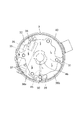
図1及び図3に示されるように、リアヘッド3のシリンダ5と対向する端面には、ロータ7の端面と摺動可能に近接するサイドブロック部31と、このサイドブロック部31の径方向外側に周方向に沿って分離した複数の凹部が形成されている。リアヘッド3の端面がシリンダ5に当接することによりこれらの凹部が閉塞され、第1高圧室32、第2高圧室40、第1貯油室38a、第2貯油室38bが形成される。第1高圧室32と吐出室28はフランジ部29に穿設された通孔30を介して連通している。
As shown in FIGS. 1 and 3, the end surface of the rear head 3 facing the cylinder 5 is provided with a side block portion 31 slidably adjacent to the end surface of the rotor 7, and radially outward of the side block portion 31. A plurality of recesses separated along the circumferential direction are formed. When the end face of the rear head 3 comes into contact with the cylinder 5, these recesses are closed, and the first high pressure chamber 32, the second high pressure chamber 40, the first oil storage chamber 38a, and the second oil storage chamber 38b are formed. The first high pressure chamber 32 and the discharge chamber 28 communicate with each other through a through hole 30 formed in the flange portion 29.
また、リアヘッド3のシリンダヘッドと対向する端面の中央には、ロータ7のベーン溝8の底部に連通して背圧を導入する背圧凹部46が形成されている。
Further, a back pressure recess 46 is formed in the center of the end face of the rear head 3 facing the cylinder head to introduce back pressure in communication with the bottom of the vane groove 8 of the rotor 7.
さらに、リアヘッド3には、吐出ガスに混在する潤滑油を分離するための遠心分離式のオイル分離器33が設けられている。このオイル分離器33は、リアヘッド3に一体に形成されているもので、導入孔34を介して第1高圧室32と連通する円柱状の空間をなすオイル分離室35を備え、このオイル分離室35にリアヘッド3と一体に形成された略円筒状の分離筒(セパレータパイプ)36を同軸上に配設して構成されている。
Further, the rear head 3 is provided with a centrifugal oil separator 33 for separating lubricating oil mixed in the discharge gas. The oil separator 33 is formed integrally with the rear head 3 and includes an oil separation chamber 35 that forms a cylindrical space that communicates with the first high-pressure chamber 32 via the introduction hole 34. A substantially cylindrical separation cylinder (separator pipe) 36 formed integrally with the rear head 3 is arranged on the same axis 35.
オイル分離室35は、駆動軸6の軸方向に対して略直交する方向に延設されると共にその軸線が鉛直線に対して斜めに傾斜するように形成されている。オイル分離室の35の上端部は、分離筒35の中心に形成された孔を介して第2高圧室40に連通し、さらにこの第2高圧室40を介して吐出口41に連通している。また、オイル分離室35の下端部は、リアヘッド3の外周面に開口し、この開口部分は、蓋部材15によって気密に封止されている。さらに、オイル分離室35の下部には、圧縮機1の下部に設けられた第1貯油室38aと連通する排油孔37が形成されている。
The oil separation chamber 35 is formed so as to extend in a direction substantially perpendicular to the axial direction of the drive shaft 6 and to have its axis inclined obliquely with respect to the vertical line. The upper end portion of the oil separation chamber 35 communicates with the second high pressure chamber 40 through a hole formed in the center of the separation cylinder 35, and further communicates with the discharge port 41 through the second high pressure chamber 40. . Further, the lower end portion of the oil separation chamber 35 opens to the outer peripheral surface of the rear head 3, and this opening portion is hermetically sealed by the lid member 15. Further, an oil drain hole 37 communicating with a first oil storage chamber 38 a provided in the lower portion of the compressor 1 is formed in the lower portion of the oil separation chamber 35.
シリンダ5のリアヘッド3に対向する端面の下部には、周方向に沿って延設された連通凹部39(図3において1点鎖線で示す)が形成されている。連通凹部39は、周方向の一端側において第1貯油室38aと連通するとともに、周方向の他端側において第2貯油室38bと連通している。
A communicating recess 39 (indicated by a one-dot chain line in FIG. 3) extending along the circumferential direction is formed at the lower portion of the end surface of the cylinder 5 facing the rear head 3. The communication recess 39 communicates with the first oil storage chamber 38a on one end side in the circumferential direction, and communicates with the second oil storage chamber 38b on the other end side in the circumferential direction.
したがって、オイル分離室35に流入された作動流体は、このオイル分離室35内に設けられた分離筒36の周りを旋回し、その過程で混在している潤滑油が分離される。潤滑油が分離除去された吐出ガスは、分離筒36の中心の孔を通って第2高圧室40に導かれた後、吐出口41を介して冷凍サイクルへ送出される。
Therefore, the working fluid that has flowed into the oil separation chamber 35 swirls around the separation cylinder 36 provided in the oil separation chamber 35, and the mixed lubricating oil is separated in the process. The discharge gas from which the lubricating oil has been separated and removed is guided to the second high-pressure chamber 40 through the hole in the center of the separation cylinder 36 and then sent to the refrigeration cycle through the discharge port 41.
また、オイル分離室35で分離された潤滑油は、オイル分離室35の下部に設けられた排油孔37を介して第1貯油室38aに導かれて貯められるとともに、連通凹部39を介して第2貯油室38bに導かれて貯められる。
In addition, the lubricating oil separated in the oil separation chamber 35 is guided and stored in the first oil storage chamber 38 a through the oil drain hole 37 provided in the lower portion of the oil separation chamber 35, and also through the communication recess 39. It is led and stored in the second oil storage chamber 38b.
さらに図3及び図5(a)に示されるように、圧縮機構を構成する部材のひとつであるリアヘッド3には、貯油室38に貯められた潤滑油を背圧凹部46に導く給油通路45が設けられている。この給油通路45は、第1貯油室38aと第2貯油室38bの間であってシリンダ5の連通凹部39に対向する箇所に圧縮機1の軸線と平行な方向に向けて穿設された第1の給油孔45aと、背圧凹部46から圧縮機1の軸線に対して径方向外側に向けて傾斜させて穿設された第2の給油孔45bとを、リアヘッド3の内部で交差させて連通することにより形成されている。
Further, as shown in FIGS. 3 and 5A, the rear head 3, which is one of the members constituting the compression mechanism, has an oil supply passage 45 that guides the lubricating oil stored in the oil storage chamber 38 to the back pressure recess 46. Is provided. The oil supply passage 45 is formed between the first oil storage chamber 38a and the second oil storage chamber 38b and at a location facing the communication recess 39 of the cylinder 5 in a direction parallel to the axis of the compressor 1. The first oil supply hole 45 a and the second oil supply hole 45 b formed by inclining radially outward from the back pressure concave portion 46 with respect to the axis of the compressor 1 are crossed inside the rear head 3. It is formed by communicating.
第1の給油孔45aは、入口近傍から所定の深さに亘って形成された大径部45a1と、大径部45a1より僅かに径が小さく大径部45a1より深い深さまで形成された中径部45a2とを備えている。大径部45a1と中径部45a2は、お互いの中心を一致させて連設するように形成されている。
The first oil supply hole 45a has a large diameter portion 45a1 formed over a predetermined depth from the vicinity of the inlet, and a medium diameter formed to a depth slightly smaller than the large diameter portion 45a1 and deeper than the large diameter portion 45a1. Part 45a2. The large-diameter portion 45a1 and the medium-diameter portion 45a2 are formed so as to be continuously arranged with their centers aligned.
第2の給油孔45bは、前記した通り、背圧凹部46から圧縮機1の軸線に対して径方向外側に向けて傾斜させて穿設されている。第2の給油孔45bの径は、第1の給油孔45aの中径部45a2の径より小さく、また、第2の給油孔45bの底端が、中径部45a2の底端近傍の側面に交差するよう穿設されている。
As described above, the second oil supply hole 45b is formed by inclining radially outward from the back pressure recess 46 with respect to the axis of the compressor 1. The diameter of the second oil supply hole 45b is smaller than the diameter of the middle diameter part 45a2 of the first oil supply hole 45a, and the bottom end of the second oil supply hole 45b is on the side surface near the bottom end of the medium diameter part 45a2. It is drilled to intersect.
したがって、貯油室38と背圧凹部46とは、シリンダ5の連通凹部39、第1の給油孔45a、及び第2の給油孔45bを介して連通している。
Therefore, the oil storage chamber 38 and the back pressure recess 46 communicate with each other via the communication recess 39 of the cylinder 5, the first oil supply hole 45a, and the second oil supply hole 45b.
さらに、給油通路45の途中には、この給油通路45を通過する潤滑油から異物を捕獲するフィルタと、前記給油通路を通過する潤滑油の圧力を減圧するオリフィスが、潤滑油の流れの方向に対してこの順序で併設するように設けられている。
Further, in the middle of the oil supply passage 45, a filter for capturing foreign matter from the lubricating oil passing through the oil supply passage 45 and an orifice for reducing the pressure of the lubricating oil passing through the oil supply passage are provided in the direction of the lubricating oil flow. On the other hand, they are provided in this order.
この例においては、図4に示されるように、ストレーナ51とオリフィス54が形成されたキャップ53とが一体に形成されたフィルタ組立体50を、第1の給油孔45aの入口に装着することにより、フィルタ(ストレーナ)とオリフィスが併設されるようになっている。
In this example, as shown in FIG. 4, a filter assembly 50 in which a strainer 51 and a cap 53 having an orifice 54 are integrally formed is attached to the inlet of the first oil supply hole 45a. A filter (strainer) and an orifice are provided side by side.
より具体的には、フィルタ組立体50は、底部にオリフィス54が形成された有底円筒状のキャップ53と、キャップ53の内側に配置され、金属網をかご状に成形したストレーナ51と、キャップ53とストレーナ51を双方の開口端を重ならせた状態でカシめて保持するリング状のホルダ52にて構成されている。
More specifically, the filter assembly 50 includes a bottomed cylindrical cap 53 having an orifice 54 formed at the bottom, a strainer 51 disposed inside the cap 53 and formed of a metal net in a basket shape, and a cap. 53 and the strainer 51 are configured by a ring-shaped holder 52 that holds the open ends in a state in which both open ends overlap each other.
ホルダ52の外径は、第1の給油孔45aの大径部45a1より僅かに大きい。また、ホルダ52の軸方向長さは、大径部45a1の深さより僅かに短い。これにより、図5(b)に示されるように、このフィルタ組立体50を第1給油孔の入口からリアヘッド3の端面まで押し込むことにより、フィルタ組立体50が第1給油孔内に軽圧入にて固定される。
The outer diameter of the holder 52 is slightly larger than the large diameter portion 45a1 of the first oil supply hole 45a. The axial length of the holder 52 is slightly shorter than the depth of the large diameter portion 45a1. Accordingly, as shown in FIG. 5B, the filter assembly 50 is lightly press-fitted into the first oil supply hole by pushing the filter assembly 50 from the inlet of the first oil supply hole to the end surface of the rear head 3. Fixed.
一方、第1の給油孔45aの中径部45a2の内径は、フィルタ組立体50のホルダ52の外径より小さく、またフィルタ組立体50のキャップ53の外径より大きい。これにより、フィルタ組立体50が大径部45a1の深さを超えてそれ以上押しこまれることが防がれる。
On the other hand, the inner diameter of the middle diameter portion 45a2 of the first oil supply hole 45a is smaller than the outer diameter of the holder 52 of the filter assembly 50 and larger than the outer diameter of the cap 53 of the filter assembly 50. This prevents the filter assembly 50 from being pushed further beyond the depth of the large diameter portion 45a1.
第2の給油孔45bと第1の給油孔45a(の中径部45a2)とは、第1の給油孔45aに挿入されたフィルタ組立体50よりも深い位置で交差しているため、中径部45a2の側面に開口した交差部が逆止弁組立体50により塞がれることはない。
Since the second oil supply hole 45b and the first oil supply hole 45a (medium diameter portion 45a2) intersect at a position deeper than the filter assembly 50 inserted into the first oil supply hole 45a, the medium diameter The intersecting portion opened to the side surface of the portion 45 a 2 is not blocked by the check valve assembly 50.
以上の構成において、圧縮機1が運転されると、圧縮室25で圧縮された高圧の作動流体は、吐出ポート26を介して吐出室28に吐出され、通孔30を介して第1高圧室32からオイル分離器33に導入される。作動流体には潤滑油が含まれており、オイル分離器33で分離された潤滑油は排油孔37を介して貯油室38に貯められる。
In the above configuration, when the compressor 1 is operated, the high-pressure working fluid compressed in the compression chamber 25 is discharged to the discharge chamber 28 via the discharge port 26, and the first high-pressure chamber via the through hole 30. 32 to the oil separator 33. The working fluid contains lubricating oil, and the lubricating oil separated by the oil separator 33 is stored in the oil storage chamber 38 through the oil drain hole 37.
貯油室38は、上述した経路を介して吐出室28の高圧圧力がほぼそのまま作用する高圧領域にある。一方、背圧凹部46は、内部の作動流体がサイドブロック部31とロータ7の隙間を通して圧縮室25に漏れるため、高圧領域より圧力が低い領域にある。このため、貯油室38に貯められた潤滑油は、貯油室38の圧力と背圧凹部46の圧力の差により、連通凹部39を介して給油通路45に送り込まれる。
The oil storage chamber 38 is in a high pressure region where the high pressure of the discharge chamber 28 acts almost as it is through the above-described path. On the other hand, the back pressure recess 46 is in a region where the pressure is lower than the high pressure region because the internal working fluid leaks into the compression chamber 25 through the gap between the side block portion 31 and the rotor 7. For this reason, the lubricating oil stored in the oil storage chamber 38 is fed into the oil supply passage 45 through the communication recess 39 due to the difference between the pressure in the oil storage chamber 38 and the pressure in the back pressure recess 46.
貯油室に貯められた潤滑油には、圧縮機構部分で発生した摩耗粉や、圧縮機1外の冷凍サイクルから吸入された異物が混入していることがある。しかしながら、給油通路45の途中にはストレーナ51とオリフィス54が一体に形成されたフィルタ組立体50が設けられているため、ストレーナ51で異物を捕獲除去した潤滑油が下流に併設されたオリフィス54に送出される。これにより、オリフィス54が異物で塞がれることなく、オリフィス54により適正に減圧された潤滑油が背圧凹部46に供給される。
The lubricating oil stored in the oil storage chamber may be mixed with wear powder generated in the compression mechanism and foreign matter sucked from the refrigeration cycle outside the compressor 1. However, since the filter assembly 50 in which the strainer 51 and the orifice 54 are integrally formed is provided in the middle of the oil supply passage 45, the lubricating oil that captures and removes the foreign matter by the strainer 51 is provided in the orifice 54 provided downstream. Sent out. As a result, the lubricating oil that has been properly depressurized by the orifice 54 is supplied to the back pressure recess 46 without the orifice 54 being blocked by foreign matter.
潤滑油がオリフィス54を通過するときに減圧するので、オリフィス54が形成されたキャップ53の上流と下流には圧力差が発生している。このため、この圧力差によりフィルタ組立体50が第1の給油孔45aの中に押し込まれていってしまう恐れが考えられる。しかしながら、フィルタ組立体50のホルダ52が圧入されている大径部45a1の内径に対して、中径部45a2の内径は十分小さいので、フィルタ組立体50が圧力差によって押し込まれてしまうことはない。
Since the pressure is reduced when the lubricating oil passes through the orifice 54, a pressure difference is generated between the upstream and downstream of the cap 53 where the orifice 54 is formed. For this reason, there is a possibility that the filter assembly 50 may be pushed into the first oil supply hole 45a due to this pressure difference. However, since the inner diameter of the middle diameter portion 45a2 is sufficiently smaller than the inner diameter of the large diameter portion 45a1 into which the holder 52 of the filter assembly 50 is press-fitted, the filter assembly 50 is not pushed in due to a pressure difference. .
ところで、リアヘッド3をダイキャストで形成した場合、鋳巣漏れの懸念を排除するために、加工工程後に含浸処理を行うことが考えられる。このような含浸処理を行った場合、十分な洗浄を行って、各部の孔等に入り込んだ含浸剤を除去する必要があるが、給油通路を方向の異なる2つの給油孔を交差させて形成した場合、各給油通路の交差した箇所よりさらに奥側の部分は、流体が流れにくい袋小路(図5、図7の符号45a4、図8の符号145a4)となる。このため、含浸処理に用いた含浸剤が袋小路部45a4、145a4で固形化したまま洗浄されず、圧縮機運転中に脱落して下流に流れていくことが考えられる。
By the way, when the rear head 3 is formed by die casting, it is conceivable to perform an impregnation treatment after the processing step in order to eliminate the fear of casting hole leakage. When such impregnation treatment is performed, it is necessary to perform sufficient cleaning to remove the impregnating agent that has entered the holes of each part, but the oil supply passage is formed by intersecting two oil supply holes with different directions. In this case, a portion further on the back side than the intersecting portion of the oil supply passages becomes a bag path (reference numeral 45a4 in FIGS. 5 and 7 and reference numeral 145a4 in FIG. 8) in which the fluid does not easily flow. For this reason, it is conceivable that the impregnating agent used for the impregnation treatment is not washed while solidified in the bag path portions 45a4 and 145a4, but falls off during the compressor operation and flows downstream.
このため、図7に示す従来の構成においては、袋小路部145a4に残留していた含浸剤Cが運転中に脱落して下流側のオリフィス145cを塞ぐ恐れがあったが、本実施形態においては、オリフィス54は袋小路部45a4の下流に設けられていないので、オリフィスが異物により塞がれて潤滑油の供給が阻害される恐れはない。
For this reason, in the conventional configuration shown in FIG. 7, the impregnating agent C remaining in the bag path portion 145a4 may fall off during operation and block the downstream orifice 145c, but in this embodiment, Since the orifice 54 is not provided downstream of the bag path 45a4, there is no possibility that the orifice is blocked by foreign matter and the supply of lubricating oil is hindered.
(第2の実施形態)
図6(a)には本発明の第2の実施形態に係る給油通路45が示されている。第2の実施形態は、第1の実施形態に比して、大径部45a1がより深く形成されている点、中径部45a2に替えてさらに外径が小さい小径部45a3が設けられている点のみ第1の実施形態と異なる。その他の構成については第1の実施形態と同じであるので、同じ符号を付して説明を省略する。 (Second Embodiment)
FIG. 6A shows anoil supply passage 45 according to the second embodiment of the present invention. The second embodiment is provided with a small-diameter portion 45a3 having a smaller outer diameter in place of the medium-diameter portion 45a2 in that the large-diameter portion 45a1 is formed deeper than the first embodiment. Only the points differ from the first embodiment. Since other configurations are the same as those of the first embodiment, the same reference numerals are given and description thereof is omitted.
図6(a)には本発明の第2の実施形態に係る給油通路45が示されている。第2の実施形態は、第1の実施形態に比して、大径部45a1がより深く形成されている点、中径部45a2に替えてさらに外径が小さい小径部45a3が設けられている点のみ第1の実施形態と異なる。その他の構成については第1の実施形態と同じであるので、同じ符号を付して説明を省略する。 (Second Embodiment)
FIG. 6A shows an
第1の給油孔45aは、入口近傍から所定の深さに亘って形成された大径部45a1と、大径部45a1より径が小さく大径部45a1より深い深さまで形成された小径部45a3とを備えている。大径部45a1と小径部45a3は、お互いの中心を一致させて連設するように形成されている。
The first oil supply hole 45a includes a large-diameter portion 45a1 formed from the vicinity of the inlet to a predetermined depth, and a small-diameter portion 45a3 formed to a depth smaller than the large-diameter portion 45a1 and deeper than the large-diameter portion 45a1. It has. The large-diameter portion 45a1 and the small-diameter portion 45a3 are formed so as to be connected with their centers aligned.
第2の給油孔45bは、背圧凹部46から圧縮機1の軸線に対して径方向外側に向けて傾斜させて穿設されている。第2の給油孔45bの径は、第1の給油孔45aの小径部45a3の径より小さく、また、第2の給油孔45bの底端が、小径部45a3の側面に交差するよう穿設されている。
The second oil supply hole 45b is formed so as to incline radially outward from the back pressure recess 46 with respect to the axis of the compressor 1. The diameter of the second oil supply hole 45b is smaller than the diameter of the small diameter part 45a3 of the first oil supply hole 45a, and the bottom end of the second oil supply hole 45b is formed so as to intersect the side surface of the small diameter part 45a3. ing.
図6(b)に示されるように、第1の給油孔45aの入口には、第1の実施形態と同様のフィルタ組立体50が装着されている。第2の実施形態においては、第1の実施形態と異なり、ホルダ52の外径が圧入される大径部45a1は、ホルダ52のみならず、キャップ53まで含んだフィルタ組立体50全体を含むことが出来る深さを有している。
As shown in FIG. 6B, a filter assembly 50 similar to that of the first embodiment is attached to the inlet of the first oil supply hole 45a. In the second embodiment, unlike the first embodiment, the large-diameter portion 45a1 into which the outer diameter of the holder 52 is press-fitted includes not only the holder 52 but also the entire filter assembly 50 including the cap 53. It has a depth that can be.
また第1の実施形態の中径部45a2に替えて、小径部45a3が、第1の給油孔45aの大径部45a1に連設するように設けられている。中径部45a2の内径がフィルタ組立体50のキャップ53の外径より大きいのに対し、小径部45a3の内径はキャップ53の外径より小さい。このため、フィルタ組立体50が小径部45a3の深さを超えてそれ以上押しこまれることが防がれる。
Also, instead of the medium diameter portion 45a2 of the first embodiment, a small diameter portion 45a3 is provided so as to be connected to the large diameter portion 45a1 of the first oil supply hole 45a. The inner diameter of the medium diameter portion 45 a 2 is larger than the outer diameter of the cap 53 of the filter assembly 50, whereas the inner diameter of the small diameter portion 45 a 3 is smaller than the outer diameter of the cap 53. For this reason, the filter assembly 50 is prevented from being pushed further beyond the depth of the small diameter portion 45a3.
特に第1の実施形態においては、ホルダ52とキャップ53のカシメ固定が緩んでしまった場合には、キャップ53のみが中径部45a2の底まで落ち込んで第2の給油孔との交差孔を塞いでしまう恐れがあるところ、この第2の実施形態においては、キャップ53が小径部45a3の中まで入りこむことができないため、キャップ53の落ち込みが防がれ、第2給油孔との交差孔が塞がれる恐れを排除することができる。
In particular, in the first embodiment, when the caulking of the holder 52 and the cap 53 is loosened, only the cap 53 falls to the bottom of the middle diameter portion 45a2 and closes the intersection hole with the second oil supply hole. In this second embodiment, since the cap 53 cannot enter the small diameter portion 45a3, the cap 53 is prevented from falling and the intersection hole with the second oil supply hole is blocked. The fear of peeling off can be eliminated.
なお、上述の例においては、フィルタ組立体50を、ストレーナ51とオリフィス54が形成されたキャップ53とをホルダ52でカシメ固定するように構成したが、キャップ53に直接ストレーナ51をカシメ固定してフィルタ組立体50としてもよい。
In the above-described example, the filter assembly 50 is configured such that the strainer 51 and the cap 53 in which the orifice 54 is formed are caulked and fixed by the holder 52, but the strainer 51 is caulked and fixed directly to the cap 53. The filter assembly 50 may be used.
また、上述の例においては、フィルタ組立体50を給油通路45の入口に設けたが、給油通路45の出口側に設けても良い。
In the above-described example, the filter assembly 50 is provided at the inlet of the oil supply passage 45, but may be provided at the outlet side of the oil supply passage 45.
1 圧縮機
2 フロントヘッド
3 リアヘッド
5 シリンダ
6 駆動軸
7 ロータ
28 吐出室
33 オイル分離器
35 オイル分離室
36 オイル分離筒
37 排油孔
38 貯油室
39 連通凹部
45 給油通路
45a 第1の給油孔
45a1 大径部
45a2 中径部
45b 第2の給油孔
46 背圧凹部
50 フィルタ組立体
51 ストレーナ
52 ホルダ
53 キャップ
54 オリフィス
C 異物 DESCRIPTION OF SYMBOLS 1Compressor 2 Front head 3 Rear head 5 Cylinder 6 Drive shaft 7 Rotor 28 Discharge chamber 33 Oil separator 35 Oil separation chamber 36 Oil separation cylinder 37 Oil drain hole 38 Oil storage chamber 39 Communication recess 45 Oil supply passage 45a First oil supply hole 45a1 Large diameter portion 45a2 Medium diameter portion 45b Second oil supply hole 46 Back pressure concave portion 50 Filter assembly 51 Strainer 52 Holder 53 Cap 54 Orifice C Foreign matter
2 フロントヘッド
3 リアヘッド
5 シリンダ
6 駆動軸
7 ロータ
28 吐出室
33 オイル分離器
35 オイル分離室
36 オイル分離筒
37 排油孔
38 貯油室
39 連通凹部
45 給油通路
45a 第1の給油孔
45a1 大径部
45a2 中径部
45b 第2の給油孔
46 背圧凹部
50 フィルタ組立体
51 ストレーナ
52 ホルダ
53 キャップ
54 オリフィス
C 異物 DESCRIPTION OF SYMBOLS 1
Claims (6)
- 潤滑油を含む流体を圧縮して吐出する圧縮機構と、高圧領域に配され、前記圧縮機構から吐出された流体から潤滑油を分離する油分離器と、この油分離器で分離された潤滑油を貯留する貯油室と、この貯油室と前記高圧領域の圧力よりも圧力が低い領域を連通する給油通路とを備え、
前記給油通路を通過する流体から異物を捕獲するフィルタと、前記給油通路を通過する流体の圧力を減圧するオリフィスを、流体の流れ方向に対してこの順序で前記給油通路内に併設したことを特徴とする圧縮機。 A compression mechanism that compresses and discharges a fluid containing lubricating oil; an oil separator that is disposed in a high pressure region and separates the lubricating oil from the fluid discharged from the compression mechanism; and the lubricating oil separated by the oil separator And an oil supply passage that communicates the oil storage chamber with a region where the pressure is lower than the pressure of the high pressure region,
A filter for capturing foreign matter from the fluid passing through the oil supply passage and an orifice for reducing the pressure of the fluid passing through the oil supply passage are provided in the oil supply passage in this order with respect to the fluid flow direction. Compressor. - 前記フィルタと前記オリフィスを一体に形成したフィルタ組立体を前記給油通路に設けることにより、前記フィルタと前記オリフィスを前記給油通路内に併設させたことを特徴とする請求項1に記載の圧縮機。 2. The compressor according to claim 1, wherein a filter assembly in which the filter and the orifice are integrally formed is provided in the oil supply passage so that the filter and the orifice are provided in the oil supply passage.
- 前記給油通路は、前記圧縮機機構を構成する部材のうちひとつ部材の内部において、この部材の第1の方向から穿設された第1の給油孔と、前記第1の方向とは異なる第2の方向から穿設された第2の給油孔を交差させることにより形成されていることを特徴とする請求項1または2に記載の圧縮機。 The oil supply passage has a first oil supply hole drilled from a first direction of the member in one of the members constituting the compressor mechanism, and a second different from the first direction. The compressor according to claim 1 or 2, wherein the compressor is formed by intersecting the second oil supply holes drilled from the direction of.
- 前記フィルタ組立体は、前記給油通路内において、前記第1の給油孔と前記第2の給油孔の交差箇所に対し流れ方向の上流側に設けられていることを特徴とする請求項3に記載の圧縮機。 The said filter assembly is provided in the upstream of the flow direction with respect to the cross | intersection location of the said 1st oil supply hole and the said 2nd oil supply hole in the said oil supply channel | path. Compressor.
- 前記フィルタ組立体は、前記給油通路内において、前記第1の給油孔と前記第2の給油孔の交差箇所に対し流れ方向の下流側に設けられていることを特徴とする請求項3に記載の圧縮機。 The said filter assembly is provided in the downstream of the flow direction with respect to the cross | intersection location of the said 1st oil supply hole and the said 2nd oil supply hole in the said oil supply channel | path. Compressor.
- 前記圧縮機構は、軸方向の両側がサイド部材で挟まれることにより閉塞されるシリンダと、前記シリンダ内に収容されると共に複数のベーン溝が形成されたロータと、前記ロータの前記ベーン溝内に収容され、先端が前記ベーン溝から出没して前記シリンダの内周面を摺動するベーンと、両側の前記サイド部材に回転可能に支持されると共に前記ロータと連結されて外部からの回転力を前記ロータに伝達する駆動軸とを備え、
前記給油通路は、前記サイド部材のうちのひとつに設けられることを特徴とする請求項3~5に記載の圧縮機。 The compression mechanism includes a cylinder that is closed when both sides in the axial direction are sandwiched between side members, a rotor that is accommodated in the cylinder and has a plurality of vane grooves, and a vane groove of the rotor. A vane that is housed and slides on the inner peripheral surface of the cylinder with its tip protruding and retracting from the vane groove, and rotatably supported by the side members on both sides and connected to the rotor to receive a rotational force from the outside. A drive shaft that transmits to the rotor,
The compressor according to any one of claims 3 to 5, wherein the oil supply passage is provided in one of the side members.
Applications Claiming Priority (2)
| Application Number | Priority Date | Filing Date | Title |
|---|---|---|---|
| JP2016120521 | 2016-06-17 | ||
| JP2016-120521 | 2016-06-17 |
Publications (1)
| Publication Number | Publication Date |
|---|---|
| WO2017217523A1 true WO2017217523A1 (en) | 2017-12-21 |
Family
ID=60663117
Family Applications (1)
| Application Number | Title | Priority Date | Filing Date |
|---|---|---|---|
| PCT/JP2017/022252 WO2017217523A1 (en) | 2016-06-17 | 2017-06-16 | Compressor |
Country Status (1)
| Country | Link |
|---|---|
| WO (1) | WO2017217523A1 (en) |
Cited By (1)
| Publication number | Priority date | Publication date | Assignee | Title |
|---|---|---|---|---|
| WO2024088338A1 (en) * | 2022-10-28 | 2024-05-02 | 杭州绿能新能源汽车部件有限公司 | Compressor |
Citations (3)
| Publication number | Priority date | Publication date | Assignee | Title |
|---|---|---|---|---|
| JP2000265984A (en) * | 1999-03-17 | 2000-09-26 | Seiko Seiki Co Ltd | Gas compressor |
| JP2006037795A (en) * | 2004-07-26 | 2006-02-09 | Calsonic Compressor Inc | Variable displacement gas compressor |
| JP2008157174A (en) * | 2006-12-26 | 2008-07-10 | Calsonic Compressor Inc | Variable displacement gas compressor |
-
2017
- 2017-06-16 WO PCT/JP2017/022252 patent/WO2017217523A1/en active Application Filing
Patent Citations (3)
| Publication number | Priority date | Publication date | Assignee | Title |
|---|---|---|---|---|
| JP2000265984A (en) * | 1999-03-17 | 2000-09-26 | Seiko Seiki Co Ltd | Gas compressor |
| JP2006037795A (en) * | 2004-07-26 | 2006-02-09 | Calsonic Compressor Inc | Variable displacement gas compressor |
| JP2008157174A (en) * | 2006-12-26 | 2008-07-10 | Calsonic Compressor Inc | Variable displacement gas compressor |
Cited By (1)
| Publication number | Priority date | Publication date | Assignee | Title |
|---|---|---|---|---|
| WO2024088338A1 (en) * | 2022-10-28 | 2024-05-02 | 杭州绿能新能源汽车部件有限公司 | Compressor |
Similar Documents
| Publication | Publication Date | Title |
|---|---|---|
| JP3874300B2 (en) | Vane pump | |
| EP2520803B1 (en) | Compressor | |
| WO2006087904A1 (en) | Vane pump | |
| KR101519698B1 (en) | Vane rotary compressor | |
| CN103671110A (en) | Vane compressor | |
| JP5708570B2 (en) | Vane type compressor | |
| WO2017217523A1 (en) | Compressor | |
| KR100937919B1 (en) | A scroll compressor improved in function of oil circulation and back pressure control | |
| WO2016190380A1 (en) | Compressor | |
| EP2236828A1 (en) | Scroll compressor | |
| JP6760836B2 (en) | Refueling structure of vane type compressor | |
| JP5409037B2 (en) | Compressor | |
| JP2006348760A (en) | Compressor | |
| JP4469742B2 (en) | Compressor | |
| WO2015093504A1 (en) | Compressor | |
| KR101823061B1 (en) | Vane compressor | |
| JP4436185B2 (en) | Compressor | |
| JP2006207544A (en) | Scroll compressor | |
| JP2018168780A (en) | Vane type compressor | |
| JP2008157174A (en) | Variable displacement gas compressor | |
| JP2005226467A (en) | Gas compressor | |
| JP2010223102A (en) | Piston type compressor | |
| JP2006233810A (en) | Scroll compressor | |
| JP2007162587A (en) | Gas compressor | |
| JP2005076527A (en) | Rotary compressor |
Legal Events
| Date | Code | Title | Description |
|---|---|---|---|
| 121 | Ep: the epo has been informed by wipo that ep was designated in this application |
Ref document number: 17813417 Country of ref document: EP Kind code of ref document: A1 |
|
| NENP | Non-entry into the national phase |
Ref country code: DE |
|
| 122 | Ep: pct application non-entry in european phase |
Ref document number: 17813417 Country of ref document: EP Kind code of ref document: A1 |
|
| NENP | Non-entry into the national phase |
Ref country code: JP |