WO2017217501A1 - エンジン始動システム、及び、始動機 - Google Patents
エンジン始動システム、及び、始動機 Download PDFInfo
- Publication number
- WO2017217501A1 WO2017217501A1 PCT/JP2017/022171 JP2017022171W WO2017217501A1 WO 2017217501 A1 WO2017217501 A1 WO 2017217501A1 JP 2017022171 W JP2017022171 W JP 2017022171W WO 2017217501 A1 WO2017217501 A1 WO 2017217501A1
- Authority
- WO
- WIPO (PCT)
- Prior art keywords
- starter
- engine
- torque
- motor
- starting
- Prior art date
- Legal status (The legal status is an assumption and is not a legal conclusion. Google has not performed a legal analysis and makes no representation as to the accuracy of the status listed.)
- Ceased
Links
Images







Classifications
-
- F—MECHANICAL ENGINEERING; LIGHTING; HEATING; WEAPONS; BLASTING
- F02—COMBUSTION ENGINES; HOT-GAS OR COMBUSTION-PRODUCT ENGINE PLANTS
- F02D—CONTROLLING COMBUSTION ENGINES
- F02D45/00—Electrical control not provided for in groups F02D41/00 - F02D43/00
-
- F—MECHANICAL ENGINEERING; LIGHTING; HEATING; WEAPONS; BLASTING
- F02—COMBUSTION ENGINES; HOT-GAS OR COMBUSTION-PRODUCT ENGINE PLANTS
- F02N—STARTING OF COMBUSTION ENGINES; STARTING AIDS FOR SUCH ENGINES, NOT OTHERWISE PROVIDED FOR
- F02N11/00—Starting of engines by means of electric motors
-
- F—MECHANICAL ENGINEERING; LIGHTING; HEATING; WEAPONS; BLASTING
- F02—COMBUSTION ENGINES; HOT-GAS OR COMBUSTION-PRODUCT ENGINE PLANTS
- F02N—STARTING OF COMBUSTION ENGINES; STARTING AIDS FOR SUCH ENGINES, NOT OTHERWISE PROVIDED FOR
- F02N11/00—Starting of engines by means of electric motors
- F02N11/04—Starting of engines by means of electric motors the motors being associated with current generators
-
- F—MECHANICAL ENGINEERING; LIGHTING; HEATING; WEAPONS; BLASTING
- F02—COMBUSTION ENGINES; HOT-GAS OR COMBUSTION-PRODUCT ENGINE PLANTS
- F02N—STARTING OF COMBUSTION ENGINES; STARTING AIDS FOR SUCH ENGINES, NOT OTHERWISE PROVIDED FOR
- F02N11/00—Starting of engines by means of electric motors
- F02N11/08—Circuits specially adapted for starting of engines
-
- Y—GENERAL TAGGING OF NEW TECHNOLOGICAL DEVELOPMENTS; GENERAL TAGGING OF CROSS-SECTIONAL TECHNOLOGIES SPANNING OVER SEVERAL SECTIONS OF THE IPC; TECHNICAL SUBJECTS COVERED BY FORMER USPC CROSS-REFERENCE ART COLLECTIONS [XRACs] AND DIGESTS
- Y02—TECHNOLOGIES OR APPLICATIONS FOR MITIGATION OR ADAPTATION AGAINST CLIMATE CHANGE
- Y02T—CLIMATE CHANGE MITIGATION TECHNOLOGIES RELATED TO TRANSPORTATION
- Y02T10/00—Road transport of goods or passengers
- Y02T10/10—Internal combustion engine [ICE] based vehicles
- Y02T10/40—Engine management systems
Definitions
- This disclosure relates to a technique for starting an engine using first and second starters.
- an engine start technique for starting an engine using a motor generator having a power generation function and a motor function in combination with a pinion dive starter see Patent Document 1.
- the timing for stopping the starter and the timing for starting the motor operation of the motor generator are set as follows.
- the timing to stop the starter is set after passing through the compression top dead center (TDC) of the engine that occurs first after the start of fuel injection.
- the timing of starting the motor operation of the motor generator is set before passing the first TDC and before reaching the next TDC.
- the timing for stopping the starter is set after passing the first TDC after the start of fuel injection.
- fuel injection is not started unless cylinder discrimination by the crank angle sensor of the engine is completed. That is, several crankings are required before fuel injection is started. In this case, re-engagement of the one-way clutch occurs before the starter is stopped. Therefore, it cannot always be said that the starting sound generated during cranking can be reduced.
- the one-way clutch is reconnected, the driving / driven state is switched between the ring gear and the pinion. The generation of the starting sound during cranking is caused by such switching between driving / driven.
- the starting sound is a gear collision sound generated by switching between driving / driven and a meshing sound between the ring gear and the pinion.
- the present disclosure provides an engine start system that can reduce a start sound generated during cranking.
- An engine start system that is an aspect of the technology of the present disclosure includes a first starter, a second starter, and a control device.
- the first starter is connected to the crankshaft of the engine and rotationally drives the crankshaft.
- the second starter cranks the engine by rotationally driving a ring gear connected to the crankshaft.
- the control device controls operations of the first starter and the second starter.
- the first starter is a motor generator having both functions of a generator and an electric motor.
- the second starter is a pinion dive starter.
- the second starter includes a motor, a pinion, a one-way clutch, and a solenoid device.
- the motor rotates upon receiving power.
- the pinion moves in the axial direction and meshes with the ring gear.
- the one-way clutch can transmit torque in only one direction from the motor side to the pinion side, and interrupts torque transmission from the pinion side to the motor side.
- the solenoid device has a function of moving the pinion in the axial direction and a function of starting / stopping (on / off) power supply to the motor.
- the required overpass torque means a torque obtained by adding the rotational torque obtained from the kinetic energy stored in the engine from the start of cranking and the drive torque that can be output by the motor operation of the first starter.
- the engine starting torque is a torque obtained by adding the compression torque of the engine and the friction torque.
- the overpass conditional expression defines a magnitude relationship in which the required overpass torque is larger than the engine start torque (required overpass torque> magnitude relationship represented by the engine start torque).
- the control device includes a start control unit and an overpass determination unit. The start control unit starts the cranking by starting the second starter in response to an engine start request, stops the operation of the second starter at a predetermined timing, and operates the motor of the first starter. To start.
- the transit determination unit determines whether or not the transit condition is satisfied after cranking is started by the second starter.
- the start control unit controls the operation of the second starter regardless of whether or not the engine has passed the first compression top dead center when the passing condition is satisfied before the engine has passed the first compression top dead center. Stop and start motor operation of the first starter.
- the engine start system determines as follows when the passing condition formula is satisfied before cranking over the first compression top dead center after cranking is started by the second starter.
- the engine start system determines that the engine can get over the first compression top dead center even if the second starter is stopped when the overtaking conditional expression is satisfied. Therefore, when the overtaking conditional expression is satisfied, the operation of the second starter can be stopped before the engine gets over the first compression top dead center.
- the engine start system of this indication can make the timing which stops operation of the 2nd starter (pinion dive starter) compared with a prior art. As a result, the driving time of the second starter can be shortened, and the meshing noise between the pinion and the ring gear can be reduced.
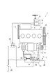
- the engine start system 1 of this embodiment is provided with the 1st starter 5, the 2nd starter 7, and the 1st control apparatus 8, as illustrated in FIG.
- the first starter 5 is connected to the crankshaft 3 of the engine 2 via a belt 4.
- the second starter 7 can be connected to a ring gear 6 attached to the crankshaft 3.
- the first control device 8 controls the operations of the first starter 5 and the second starter 7.
- the first control device 8 has a built-in microcomputer, for example.
- the microcomputer includes a CPU that realizes a control function and an arithmetic function, a storage device (memory) of ROM and RAM, an input / output device of I / O, and the like.
- the storage device includes a non-transitional tangible recording medium. Signals (detection information) indicating detection values are input to the first control device 8 from various detectors that detect the state of the engine 2.
- the first control device 8 outputs a signal (control information) for controlling the engine 2 based on the input signal.
- the first starter 5 is a motor generator having functions of both a generator and an electric motor.
- the first starter 5 includes a second control device 9 different from the first control device 8, and the operation is controlled by the second control device 9.
- the second control device 9 includes a microcomputer including a CPU, a ROM, a RAM, an I / O, and the like.
- a signal indicating a control command is input from the first controller 8 to the second controller 9.
- Signals (detection information) indicating detection values are input to the second control device 9 from various detectors that detect the state of the first starter 5 and the like.
- the second control device 9 outputs a signal (control information) for controlling the first starter 5 based on these input signals.
- the second control device 9 includes an inverter circuit for adjusting the voltage and frequency applied to the first starter 5.
- the microcomputer of the second control device 9 can arbitrarily control the rotation speed of the first starter 5 by outputting a signal to the inverter circuit.
- the second starter 7 pushes the pinion 10 in the A direction (right direction in FIG. 1) that is the axial direction, and meshes with the ring gear 6. Then, the second starter 7 transmits the torque generated in the motor 11 to the pinion 10 and rotationally drives the ring gear 6.
- the second starter 7 is a well-known pinion dive starter.
- the second starter 7 includes the following clutch 12 and electromagnetic switch 13 and the like.
- the clutch 12 is a one-way clutch that transmits torque in only one direction.
- the clutch 12 transmits torque generated in the motor 11 from the motor side to the pinion side.
- the clutch 12 blocks torque transmission from the pinion side to the motor side.
- the electromagnetic switch 13 includes a solenoid 14 and a plunger 15.
- the solenoid 14 generates an electromagnetic force when energized.
- the plunger 15 is attracted in the B direction (left direction in FIG. 1) by the electromagnetic force of the solenoid 14.
- the electromagnetic switch 13 moves the pinion 10 in the A direction (the right direction in FIG. 1) in conjunction with the movement of the plunger 15.
- the electromagnetic switch 13 opens and closes the main contact 16 provided on the power supply line of the motor 11 to start / stop (on / off) power supply to the motor 11.
- the first control device 8 has functions of a start control unit 17 and an overriding determination unit 18.
- the start control unit 17 controls the operations of the first and second starters 5 and 7 when the engine 2 is started.
- the overpass determining unit 18 determines whether or not a pass over conditional expression described later is satisfied after cranking of the engine 2 is started.
- the start control unit 17 and the transit determination unit 18 are realized (by software) by the CPU executing a program stored in a storage device (memory) included in the microcomputer, for example. Also good.
- the implementation methods of the start control unit 17 and the overpass determination unit 18 are not limited to this.
- the start control unit 17 and the overpass determination unit 18 may be realized (by hardware) by combining electronic circuits such as ICs.
- the first control device 8 determines whether or not a start request for the engine 2 has been input (step S1).
- the engine 2 start request is output at the following times. For example, after the idling stop is executed, when the driver performs an operation of loosening the brake pedal, or when the operation of switching the shift lever from the N range (neutral) to the D range (driving) is performed. .
- the idling stop is a known technique for automatically stopping the engine 2 when the vehicle is temporarily stopped at an intersection or the like.
- the first control device 8 repeats the process of step S1 until a start request for the engine 2 is input (step S1: NO). On the other hand, when the start request for the engine 2 is input (step S1: YES), the first control device 8 proceeds to the process of step S2.
- the first control device 8 performs the following start control on the second starter 7 by the start control unit 17. Specifically, the start control unit 17 outputs an on signal (start signal) to a relay 19 (see FIG. 1) provided in the energization line of the solenoid 14 and turns on the electromagnetic switch 13 to thereby perform the second start.
- the machine 7 is activated (step S2).
- the relay 19 When the relay 19 is turned on, the electromagnetic switch 13 energizes the solenoid 14 from the battery 20 to generate electromagnetic force.
- the plunger 15 is attracted by the electromagnetic force and moves in the B direction (left direction in FIG. 1).
- the pinion 10 is pushed out in the A direction (the right direction in FIG. 1) and meshes with the ring gear 6.
- the main contact 16 is closed, and electric power is supplied from the battery 20 to the motor 11.
- the torque of the motor 11 is transmitted to the pinion 10 via the clutch 12 and rotationally drives the ring gear 6.
- the first control device 8 determines whether or not the engine 2 has passed the first compression top dead center (first TDC) (step S3). Whether the engine 2 has passed the first TDC can be determined based on the following information. For example, the engine speed can be detected by an existing crank angle sensor (not shown) (for example, the engine speed can be calculated based on the crank angle detected by the crank angle sensor). Further, the determination may be made based on at least one information of the rotation speed, torque, and current of the first starter 5 connected to the crankshaft 3. If the engine 2 has not overtaken the first TDC (step S3: NO), the first control device 8 proceeds to the process of step S4. On the other hand, when the engine 2 has passed the first TDC (step S3: YES), the first control device 8 proceeds to the process of step S5.
- first TDC first compression top dead center
- the first control device 8 determines whether or not the overpass conditional expression is satisfied by the overpass determining unit 18 (step S4).
- the overpass conditional expression is a predetermined condition for determining whether or not the engine 2 can get over the first TDC when the operation of the second starter 7 is stopped before the engine 2 gets over the first TDC.
- the required overpass torque is a torque obtained by adding the rotational torque obtained from the kinetic energy stored in the engine 2 from the start of cranking and the drive torque that can be output by the motor operation of the first starter 5.
- the engine starting torque is a torque obtained by adding the compression torque of the engine 2 and the friction torque.
- the overpassing determination unit 18 calculates the drive torque that can be output from the first starter 5 based on the output restriction map (data map) of the second control device 9.
- 3A and 3B illustrate an output restriction map according to the present embodiment.
- the output restriction map is data indicating a correlation between the drive torque that can be output from the first starter 5 and the engine speed.
- the drive torque that can be output from the first starter 5 is calculated by applying the engine speed to the output restriction map.
- the rotational speed value Nec illustrated in FIG. 3A is a rotational speed that can be switched from cranking by the second starter 7 to cranking by the first starter 5. Therefore, before the engine speed reaches Nec, the output restriction map may be set as follows in order to prevent the overtaking conditional expression from being satisfied. As illustrated in FIG. 3B, in the output restriction map, the numerical value of the drive torque may be set to zero in a range where the engine speed is equal to or less than Neu, which is slightly larger than Nec.
- the rotational torque obtained from the kinetic energy stored in the engine 2 can be calculated from the inertia moment of the rotating system including the crankshaft 3 and the ring gear 6 and the engine speed. Therefore, by inputting a known value to the inertia moment of the rotating system, the engine speed that can be overridden can be calculated.
- the pass-over determination unit 18 can determine whether or not the pass-over conditional expression is satisfied using the engine speed that can be used as a determination condition. That is, when the engine speed that can be detected by the crank angle sensor or the like exceeds the engine speed that can be passed over, the passing-over conditional expression is established.
- the first control device 8 proceeds to the process of step S5 when the overtaking conditional expression is satisfied (step S4: YES).
- the first control device 8 returns to the process of step S3 when the passing over conditional expression is not satisfied (step S4: NO).
- the first control device 8 performs the following stop control on the second starter 7 by the start control unit 17. Specifically, the start control unit 17 outputs an off signal (stop signal) to the relay 19 to turn off the electromagnetic switch 13, thereby stopping the operation of the second starter 7 (step S5).
- the electromagnetic switch 13 is turned off, in the second starter 7, the pinion 10 is disengaged from the ring gear 6 and the main contact 16 is opened, and the power supply from the battery 20 to the motor 11 is stopped.
- the relay 19 functions as a stop signal receiving unit that receives a stop signal for stopping the operation of the second starter 7.
- the first control device 8 performs the following operation control on the first starter 5 by the start control unit 17. Specifically, the start control unit 17 outputs a drive command (start signal) to the second control device 9 and starts the motor operation of the first starter 5 (step S6).
- the timing for starting the motor operation of the first starter 5 is before the engine 2 gets over the first TDC. For example, as illustrated in the time chart of FIG. 4, the timing is the same as when the operation of the second starter 7 is stopped.
- the 2nd control apparatus 9 functions as a start signal receiving part which receives the start signal which starts the motor operation
- the first control device 8 determines whether or not the engine 2 has completely exploded (step S7).
- the determination as to whether or not the engine 2 has completely detonated can be made, for example, when the engine speed exceeds a preset complete explosion speed and it is determined that the engine 2 has completely detonated. Until the engine 2 is completely exploded (step S7: NO), the process of step S7 is repeated. On the other hand, if it is determined that the engine 2 has exploded completely (step S7: YES), the first control device 8 proceeds to the process of step S8.
- the first control device 8 controls the first starter 5 by the start control unit 17 as follows.
- the start control unit 17 outputs a stop command to the second control device 9 to stop the motor operation of the first starter 5 (step S8).
- the first starter 5 is connected to the crankshaft 3 via the belt 4. Therefore, the first starter 5 functions as a generator after stopping the motor operation.
- the engine start system 1 of the present embodiment starts up the second starter 7 and starts cranking. After the engine 2 gets over the first TDC, Once established, control is performed as follows. For example, the engine start system 1 stops the operation of the second starter 7 and starts the motor operation of the first starter 5 at the timing when the passing-over conditional expression is satisfied (t1). That is, the engine start system 1 performs the cranking by switching from the second starter 7 to the first starter 5.
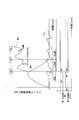
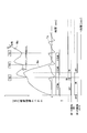
- FIG. 4 exemplifies a graph showing fluctuations in the engine rotational speed Ne, the motor rotational speed Nm of the second starter 7, and the engine starting torque Te ( ⁇ compression torque + friction torque).
- the time chart which shows the on / off timing of the 1st starter 5 and the 2nd starter 7 is illustrated.
- the motor rotation speed Nm is a rotation speed converted into the rotation speed of the crankshaft 3 from the gear ratio between the pinion 10 and the ring gear 6.
- the engine start system 1 of this embodiment can make the timing which stops operation
- the driving time of the second starter 7 (the time during which the pinion 10 is engaged with the ring gear 6) is shortened. Therefore, the meshing sound at the time of cranking can be reduced.
- the present embodiment is a first case in which the engine 2 gets over the first TDC (first compression top dead center) without satisfying the overtaking conditional expression.
- the operation of the second starter 7 is stopped and the motor operation of the first starter 5 is started before the clutch coupling timing.
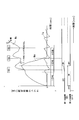
- the timing for starting the motor operation of the first starter 5 can be set to any one of three patterns as illustrated in the time chart of FIG. Specifically, (1) before the timing of stopping the operation of the second starter 7, (2) the same as the timing of stopping the operation of the second starter 7, (3) the operation of the second starter 7 It can be set to either after the stop timing. In either case, it is before the clutch engagement timing.
- the clutch engagement timing is a timing at which the clutch 12 is estimated to be reconnected when the second starter 7 continues cranking.
- This clutch coupling timing is a timing at which the motor speed of the second starter 7 catches up with the engine speed after the clutch 12 is disengaged after the engine 2 gets over the first TDC. Therefore, it can be estimated by monitoring at least the engine speed.
- the operation of the second starter 7 is stopped before the clutch engagement timing even when the engine 2 has passed the first TDC without satisfying the overtaking conditional expression. Thereby, in this embodiment, the recombination of the clutch 12 does not occur. As a result, there is no generation of gear collision noise associated with the re-engagement of the clutch 12. Therefore, it is possible to reduce the starting sound generated during cranking.
- the motor operation of the first starter 5 is started before the clutch coupling timing.
- movement of the 2nd starter 7 is somewhat delayed, the clutch 12 does not rejoin.
- generation of gear collision noise can be avoided.
- the timing of starting the motor operation of the first starter 5 is (3), it is necessary to supply power to both the first starter 5 and the second starter 7 at the same time. Absent. That is, when the timing for starting the motor operation of the first starter 5 is set after the timing for stopping the operation of the second starter 7, both the first starter 5 and the second starter 7 are set. There is no need to supply power at the same time.
- the timing for starting the motor operation of the first starter 5 is (3), a large instantaneous power is not required when starting the motor operation of the first starter 5. . Thereby, the instantaneous interruption of the battery 20 can be prevented.
- the second control device 9 includes functions of a start control unit 17 and a ride-over determination unit 18.
- the control procedure at the time of engine start of this embodiment is the same as that of the first embodiment. Therefore, the description is abbreviate
- the second control device 9 includes functions of a start control unit 17 and a ride-over determination unit 18.
- a command for the relay 19 (a command for the second starter 7) is issued from the second control device 9 via the first control device 8.
- the control procedure at the time of engine start of this embodiment is the same as that of the first embodiment. Therefore, the description is abbreviate
- This embodiment is an example in the case of using a tandem solenoid starter for the second starter 7.
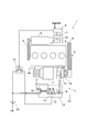
- the electromagnetic switch 13 of the second starter 7 includes first and second solenoids 22 and 23 as illustrated in FIG.
- the first solenoid 22 is a solenoid for pushing out the pinion 10.
- the second solenoid 23 is a solenoid for opening and closing the main contact 16.
- the operations of the first and second solenoids 22 and 23 are independently controlled by the first control device 8.
- the control procedure at the time of engine start executed by the first control device 8 of the present embodiment will be described with reference to the flowchart illustrated in FIG. 9. A detailed description of processing (steps) common to the first embodiment will be omitted (see FIG. 2 of the first embodiment).
- the first control device 8 determines whether or not a start request for the engine 2 has been input (step S11).
- the first control device 8 performs the following start control on the second starter 7 by the start control unit 17. Specifically, the start control unit 17 outputs an ON signal to the first and second relays 24 and 25 (see FIG. 8) and energizes the first and second solenoids 22 and 23 to thereby generate the second signal.
- the starter 7 is activated (step S12).
- the first solenoid 22 is energized from the battery 20 to generate electromagnetic force.
- the first plunger 26 is attracted by the electromagnetic force and moves in the B direction (left direction in FIG. 8).
- the second solenoid 23 is energized from the battery 20 to generate an electromagnetic force.
- the second plunger 27 is attracted by the electromagnetic force and moves in the C direction (the right direction in FIG. 8).
- the pinion 10 is pushed out in the A direction (right direction in FIG. 8) by the operation of the first solenoid 22 and meshes with the ring gear 6.
- the operation of the second solenoid 23 closes the main contact 16, and power is supplied from the battery 20 to the motor 11.
- the torque of the motor 11 is transmitted to the pinion 10 via the clutch 12 and rotationally drives the ring gear 6.
- the first control device 8 determines whether or not the engine 2 has passed the first TDC (first compression top dead center) (step S13). The first control device 8 determines whether or not the overpass conditional expression is satisfied by the overpass determining unit 18 (step S14). The first control device 8 outputs an off signal to the first relay 24 by the start control unit 17, and stops energization of the first solenoid 22 (step S15). When the energization of the first solenoid 22 is stopped, the pinion 10 is detached from the ring gear 6 in the second starter 7. The first control device 8 controls the first starter 5 by the start control unit 17 as follows. Specifically, the start control unit 17 outputs a drive command to the second control device 9 and starts the motor operation of the first starter 5 (step S16).
- the first control device 8 outputs an off signal to the second relay 25 by the start control unit 17 to stop energization of the second solenoid 23.
- the main contact 16 is opened, and the power supply from the battery 20 to the motor 11 is stopped. Thereby, the operation of the second starter 7 is stopped.
- the first control device 8 determines whether or not the engine 2 has completely exploded (step S17).
- the first control device 8 controls the first starter 5 by the start control unit 17 as follows. Specifically, the start control unit 17 outputs a stop command to the second control device 9 to stop the motor operation of the first starter 5 (step S18).
- the following control is performed. Specifically, before the power supply to the motor 11 is stopped by stopping the energization to the second solenoid 23, the energization to the first solenoid 22 is stopped and the pinion 10 is detached from the ring gear 6. Thereby, in this embodiment, the recombination of the clutch 12 does not occur substantially. Therefore, in this embodiment, after the drive command for starting the motor operation of the first starter 5 is output to the second controller 9, the motor operation of the first starter 5 is actually started. Even if there is a time difference between the start time and the start time, the starting sound generated during cranking can be reduced.
- the present embodiment is an example in the case where the timing for stopping the operation of the second starter 7 and the timing for starting the motor operation of the first starter 5 are changed according to the initial crank angle.
- the initial crank angle refers to a crank angle when cranking is started by the second starter 7 (when the crankshaft 3 is stationary).
- the rotational torque obtained from the kinetic energy stored in the engine 2 from the start of cranking increases and decreases depending on the initial crank angle. Therefore, by grasping the initial crank angle, the drive torque that can be output by the motor operation of the first starter 5 can be reduced. As a result, the power consumption of the first starter 5 can be reduced.
- This embodiment is a second case where the engine 2 has passed the first TDC (first compression top dead center) without satisfying the passing conditional expression.
- the operation control of the first and second starters 5 and 7 by the start control unit 17 is different from the second embodiment.
- the first starter 5 is operated as an electric motor before the engine 2 gets over the first TDC.
- the first starter 5 outputs a driving torque having a value smaller than an upper limit value that can be set based on the output restriction map shown in FIG. 3A, for example. Thereafter, the first starter 5 keeps the drive torque at this small value (see the ON1 period shown in FIG. 10).
- the operation of the second starter 7 is stopped before the clutch coupling timing. Further, in the present embodiment, the drive torque of the first starter 5 is increased stepwise to the target value (see the transition from ON1 to ON2 shown in FIG. 10). Thereby, in this embodiment, before the engine 2 gets over the first TDC, the operation check of the first starter 5 can be performed.
- timing of raising the drive torque of the first starter 5 described above may be before or after the operation of the second starter 7 is stopped.
- the timing for raising the driving torque of the first starter 5 and the timing for stopping the operation of the second starter 7 may be changed according to the initial crank angle.
- the present embodiment is a third case in which the engine 2 gets over the first TDC without the overtaking conditional expression being satisfied.
- the operation control of the first and second starters 5 and 7 by the start control unit 17 is different from the seventh embodiment.
- the first starter 5 is operated as an electric motor before the engine 2 gets over the first TDC.
- the drive torque is increased linearly (the drive torque is increased over time). Increase proportionally).
- the operation of the second starter 7 is stopped before the clutch engagement timing. Further, in the present embodiment, the drive torque of the first starter 5 is raised to the target value in a step shape.
- timing of raising the drive torque of the first starter 5 described above may be before or after the operation of the second starter 7 is stopped.
- the timing for raising the driving torque of the first starter 5 and the timing for stopping the operation of the second starter 7 may be changed according to the initial crank angle.
- the present embodiment is a fourth case where the engine 2 gets over the first TDC without the overtaking conditional expression being satisfied.
- This embodiment is different from the seventh and eighth embodiments in the operation control of the first and second starters 5 and 7 by the start control unit 17.
- the first starter 5 is operated as an electric motor before the engine 2 gets over the first TDC.
- the present embodiment temporarily stops the first starter 5 as an electric motor, as illustrated in FIG.
- the operation of the second starter 7 is stopped before the clutch engagement timing.
- the first starter 5 is operated as an electric motor.
- the peak value of the compression torque can be calculated by monitoring the battery voltage or the battery current.
- the compression torque is considerably larger than the friction torque (compression torque >> friction torque). Therefore, the ratio of the compression torque is large in the engine starting torque in the compression stroke.
- This compression torque peaks slightly before TDC (compression top dead center). Further, at the peak position of the compression torque, the slopes of the battery voltage and the battery current are substantially zero.
- the peak value of the compression torque can be calculated by grasping in advance the correlation between the value of the battery voltage or battery current near the zero slope and the compression torque.
- the engine starting system 1 detects the in-cylinder pressure of the engine 2 by using an existing in-cylinder pressure sensor. Then, the first control device 8 can calculate the compression torque by theoretical calculation based on the detection result.
- the engine start system 1 has shown the example in which the rotation angle (crank angle) of the crankshaft 3 is detected by the crank angle sensor.
- the first starter 5 is connected to the crankshaft 3 via the belt 4. Therefore, the engine start system 1 detects the rotation angle of the first starter 5 using a rotation angle sensor provided in the first starter 5. Then, the crank angle is estimated based on the rotation angle.
- the engine start system 1 can determine the timing of passing the first TDC (first compression top dead center) even if the crank angle sensor is not provided.
- addition of a sensor, a branch of sensor wiring, etc. become unnecessary. As a result, the system can be simplified. Moreover, cost can be reduced.
- the 1st starter 5 of 1st Embodiment is connected with the crankshaft 3 via the belt 4, it is not this limitation.
- a clutch may be built in the pulley of the first starter 5 around which the belt 4 is stretched.
- an example in which the overpass conditional expression includes a drive torque that can be output from the first starter 5 is not limited thereto.
- An overtaking conditional expression that does not include the drive torque that can be output from the first starter 5 may be set.
- the overriding determination unit 18 included in the first control device 8 includes a rotation torque obtained from kinetic energy stored in the engine 2 from the start of cranking, and an engine starting torque (compression torque of the engine 2 + friction torque). Based on the magnitude relationship, it may be determined whether the operation of the second starter 7 can be stopped before the engine 2 gets over the first TDC (first compression top dead center).
- the timing when the operation of the second starter 7 is stopped, and the first starter 5 It is not necessary to match the timing of starting the motor operation. That is, the timing for starting the motor operation of the first starter 5 does not necessarily have to be before TDC (compression top dead center). It may be before the clutch engagement timing at the latest.
Landscapes
- Engineering & Computer Science (AREA)
- Chemical & Material Sciences (AREA)
- Combustion & Propulsion (AREA)
- Mechanical Engineering (AREA)
- General Engineering & Computer Science (AREA)
- Control Of Vehicle Engines Or Engines For Specific Uses (AREA)
- Combined Controls Of Internal Combustion Engines (AREA)
Abstract
第1制御装置8は、始動制御部17及び乗り越し判断部18を有する。始動制御部17は、第2始動機7を起動してクランキングを開始した後、所定のタイミングで第2始動機の動作を停止し、且つ、第1始動機5のモータ動作を開始する。乗り越し判断部18は、第2始動機により、クランキングが開始された後、所定の乗り越し条件式が成立するか否かを判断する。始動制御部は、エンジン2が最初の圧縮上死点を乗り越す前に、乗り越し条件式が成立したとき、エンジンが最初の圧縮上死点を乗り越したか否かに関係なく、第2始動機の動作を停止し、且つ、第1始動機のモータ動作を開始する。
Description
本開示は、第1及び第2始動機を用いてエンジンの始動を行う技術に関する。
例えば、発電機能及びモータ機能を備えるモータジェネレータと、ピニオン飛び込み式のスタータと、を併用して、エンジンの始動を行うエンジン始動技術が知られている(特許文献1参照)。
この技術では、スタータを起動して、エンジンのクランキングを開始した後、スタータを停止するタイミングと、モータジェネレータのモータ動作を開始するタイミングと、を以下のように設定している。スタータを停止するタイミングは、燃料噴射の開始後、最初に発生するエンジンの圧縮上死点(TDC)を通過した以降に設定される。モータジェネレータのモータ動作を開始するタイミングは、最初のTDCを通過してから次のTDCに達する前に設定される。
この技術では、スタータを起動して、エンジンのクランキングを開始した後、スタータを停止するタイミングと、モータジェネレータのモータ動作を開始するタイミングと、を以下のように設定している。スタータを停止するタイミングは、燃料噴射の開始後、最初に発生するエンジンの圧縮上死点(TDC)を通過した以降に設定される。モータジェネレータのモータ動作を開始するタイミングは、最初のTDCを通過してから次のTDCに達する前に設定される。
上記技術では、スタータを停止するタイミングを、燃料噴射の開始後、最初のTDCを通過した以降に設定している。しかし実際は、エンジンのクランク角センサによる気筒判別が完了しないと、燃料噴射が開始されない。すなわち、燃料噴射が開始されるまでに、数回のクランキングが必要になる。この場合、スタータを停止させるまでに、一方向クラッチの再結合が発生する。そのため、必ずしもクランキング中に発生する始動音を小さくできるとは言えない。一方向クラッチが再結合するときには、リングギヤとピニオンとの間で、駆動/被駆動が入れ替わる。クランキング中の始動音の発生は、このような駆動/被駆動の入れ替わりに起因する。具体的には、始動音は、駆動/被駆動の入れ替わりによって発生するギヤ衝突音、及び、リングギヤとピニオンとの噛み合い音である。
また、上記技術では、燃料噴射の開始後、最初のTDCを通過した以降に、スタータの動作を停止する。よって、スタータの駆動時間を短くすることが困難である。これにより、リングギヤとピニオンとの噛み合い音が発生する時間は長くなる。
本開示は、クランキング中に発生する始動音を低減できるエンジン始動システムを提供する。
本開示は、クランキング中に発生する始動音を低減できるエンジン始動システムを提供する。
本開示の技術の一態様であるエンジン始動システムは、第1始動機、第2始動機、及び制御装置を備える。第1始動機は、エンジンのクランク軸に連結されて、クランク軸を回転駆動する。第2始動機は、クランク軸に連結されるリングギヤを回転駆動することによって、エンジンをクランキングする。制御装置は、第1始動機及び第2始動機の動作を制御する。
前記第1始動機は、発電機と電動機との両方の機能を備えるモータジェネレータである。第2始動機は、ピニオン飛び込み式スタータである。第2始動機は、モータ、ピニオン、一方向クラッチ、及びソレノイド装置を含んで構成される。モータは、電力供給を受けて回転する。ピニオンは、軸方向に移動してリングギヤに噛み合う。一方向クラッチは、モータ側からピニオン側への一方向のみのトルクを伝達でき、ピニオン側からモータ側へのトルク伝達を遮断する。ソレノイド装置は、ピニオンを軸方向に移動させる機能、及び、モータへの電力供給を開始・停止(オン・オフ)する機能を備える。
前記第1始動機は、発電機と電動機との両方の機能を備えるモータジェネレータである。第2始動機は、ピニオン飛び込み式スタータである。第2始動機は、モータ、ピニオン、一方向クラッチ、及びソレノイド装置を含んで構成される。モータは、電力供給を受けて回転する。ピニオンは、軸方向に移動してリングギヤに噛み合う。一方向クラッチは、モータ側からピニオン側への一方向のみのトルクを伝達でき、ピニオン側からモータ側へのトルク伝達を遮断する。ソレノイド装置は、ピニオンを軸方向に移動させる機能、及び、モータへの電力供給を開始・停止(オン・オフ)する機能を備える。
乗り越し必要トルクとは、クランキングの開始からエンジンに蓄えられる運動エネルギーによって得られる回転トルクと、第1始動機のモータ動作によって出力可能な駆動トルクと、を加算したトルクをいう。エンジン始動トルクとは、エンジンの圧縮トルクと、フリクショントルクと、を加算したトルクをいう。乗り越し条件式には、乗り越し必要トルクがエンジン始動トルクより大きい大小関係(乗り越し必要トルク>エンジン始動トルクで表される大小関係)を定義する。制御装置は、始動制御部及び乗り越し判断部を有する。始動制御部は、エンジンの始動要求により、第2始動機を起動してクランキングを開始した後、所定のタイミングで、第2始動機の動作を停止し、且つ、第1始動機のモータ動作を開始する。乗り越し判断部は、第2始動機により、クランキングが開始された後、乗り越し条件式が成立するか否かを判断する。始動制御部は、エンジンが最初の圧縮上死点を乗り越す前に、乗り越し条件式が成立したとき、エンジンが最初の圧縮上死点を乗り越したか否かに関係なく、第2始動機の動作を停止し、且つ、第1始動機のモータ動作を開始する。
本開示のエンジン始動システムは、第2始動機により、クランキングが開始された後、エンジンが最初の圧縮上死点を乗り越す前に、乗り越し条件式が成立すると、次のように判断する。エンジン始動システムは、乗り越し条件式が成立した時点で、第2始動機を停止しても、エンジンが最初の圧縮上死点を乗り越せると判断する。よって、乗り越し条件式が成立したときは、エンジンが最初の圧縮上死点を乗り越す前に、第2始動機の動作を停止させられる。これにより、本開示のエンジン始動システムは、従来技術と比較して、第2始動機(ピニオン飛び込み式スタータ)の動作を停止するタイミングを早くできる。その結果、第2始動機の駆動時間を短くでき、ピニオンとリングギヤとの噛み合い音を低減できる。
本開示の技術を実施するための形態について、図面を参照し詳細に説明する。
〔第1実施形態〕
本実施形態のエンジン始動システム1は、図1に例示するように、第1始動機5、第2始動機7、及び第1制御装置8を備える。第1始動機5は、エンジン2のクランク軸3に、ベルト4を介して連結される。第2始動機7は、クランク軸3に取り付けられたリングギヤ6に連結可能である。第1制御装置8は、第1始動機5及び第2始動機7の動作を制御する。なお、第1制御装置8は、例えばマイクロコンピュータを内蔵している。マイクロコンピュータは、制御機能や演算機能を実現するCPU、ROMやRAMの記憶装置(メモリ)、I/Oの入出力装置等を備える。記憶装置には、非遷移的実体的記録媒体が含まれる。第1制御装置8には、エンジン2の状態を検出する各種検出器から、検出値を示す信号(検出情報)が入力される。第1制御装置8は、この入力信号に基づいて、エンジン2を制御するための信号(制御情報)を出力する。
本実施形態のエンジン始動システム1は、図1に例示するように、第1始動機5、第2始動機7、及び第1制御装置8を備える。第1始動機5は、エンジン2のクランク軸3に、ベルト4を介して連結される。第2始動機7は、クランク軸3に取り付けられたリングギヤ6に連結可能である。第1制御装置8は、第1始動機5及び第2始動機7の動作を制御する。なお、第1制御装置8は、例えばマイクロコンピュータを内蔵している。マイクロコンピュータは、制御機能や演算機能を実現するCPU、ROMやRAMの記憶装置(メモリ)、I/Oの入出力装置等を備える。記憶装置には、非遷移的実体的記録媒体が含まれる。第1制御装置8には、エンジン2の状態を検出する各種検出器から、検出値を示す信号(検出情報)が入力される。第1制御装置8は、この入力信号に基づいて、エンジン2を制御するための信号(制御情報)を出力する。
第1始動機5は、発電機及び電動機の両方の機能を有するモータジェネレータである。第1始動機5は、第1制御装置8とは別の第2制御装置9を備え、第2制御装置9により動作が制御される。なお、第2制御装置9は、第1制御装置8と同様に、CPU、ROM、RAM、I/O等を備えるマイクロコンピュータを内蔵している。第2制御装置9には、第1制御装置8から、制御指令を示す信号が入力される。第2制御装置9には、第1始動機5等の状態を検出する各種検出器から、検出値を示す信号(検出情報)が入力される。第2制御装置9は、これらの入力信号に基づいて、第1始動機5を制御するための信号(制御情報)を出力する。また、第2制御装置9は、第1始動機5に印加する電圧及び周波数を調整するためのインバータ回路を備える。第2制御装置9のマイクロコンピュータは、インバータ回路に信号を出力することによって、第1始動機5の回転速度を任意に制御できる。
第2始動機7は、ピニオン10を軸方向であるA方向(図1の右方向)に押し出して、リングギヤ6に噛み合わせる。そして、第2始動機7は、モータ11に発生するトルクをピニオン10に伝達して、リングギヤ6を回転駆動する。このように、第2始動機7は、周知のピニオン飛び込み式スタータである。第2始動機7は、以下のクラッチ12及び電磁スイッチ13等を含んで構成される。
クラッチ12は、トルクの伝達を一方向のみに行う一方向クラッチである。クラッチ12は、モータ11に発生するトルクを、モータ側からピニオン側へ伝達する。一方、クラッチ12は、ピニオン側からモータ側へのトルク伝達を遮断する。
電磁スイッチ13は、ソレノイド14及びプランジャ15等を含んで構成される。ソレノイド14は、通電によって電磁力を発生する。プランジャ15は、ソレノイド14の電磁力によって、B方向(図1の左方向)へ吸引される。電磁スイッチ13は、プランジャ15の動きに連動して、ピニオン10をA方向(図1の右方向)に移動させる。そして、電磁スイッチ13は、モータ11の電源ラインに設けられるメイン接点16を開閉して、モータ11への電力供給を開始・停止(オン・オフ)する。
クラッチ12は、トルクの伝達を一方向のみに行う一方向クラッチである。クラッチ12は、モータ11に発生するトルクを、モータ側からピニオン側へ伝達する。一方、クラッチ12は、ピニオン側からモータ側へのトルク伝達を遮断する。
電磁スイッチ13は、ソレノイド14及びプランジャ15等を含んで構成される。ソレノイド14は、通電によって電磁力を発生する。プランジャ15は、ソレノイド14の電磁力によって、B方向(図1の左方向)へ吸引される。電磁スイッチ13は、プランジャ15の動きに連動して、ピニオン10をA方向(図1の右方向)に移動させる。そして、電磁スイッチ13は、モータ11の電源ラインに設けられるメイン接点16を開閉して、モータ11への電力供給を開始・停止(オン・オフ)する。
第1制御装置8は、始動制御部17及び乗り越し判断部18の機能を有する。始動制御部17は、エンジン2の始動時に、第1及び第2始動機5,7の動作を制御する。乗り越し判断部18は、エンジン2のクランキングが開始された後、後述する乗り越し条件式が成立するか否かを判断する。なお、始動制御部17及び乗り越し判断部18は、以降に説明するように、例えばマイクロコンピュータが備える記憶装置(メモリ)に記憶されているプログラムをCPUが実行することによって(ソフトウェアによって)実現してもよい。始動制御部17及び乗り越し判断部18の実現方法はこれに限らない。始動制御部17及び乗り越し判断部18は、例えばIC等の電子回路を組み合わせることによって(ハードウェアによって)実現してもよい。
以下、本実施形態の第1制御装置8により実行されるエンジン始動時の制御手順を、図2に例示するフローチャートに従って説明する。下記のステップS1~S8は、図2に例示するフローチャートの各処理に付したS1~S8に該当する。
以下、本実施形態の第1制御装置8により実行されるエンジン始動時の制御手順を、図2に例示するフローチャートに従って説明する。下記のステップS1~S8は、図2に例示するフローチャートの各処理に付したS1~S8に該当する。
第1制御装置8は、エンジン2の始動要求が入力された否かを判断する(ステップS1)。エンジン2の始動要求は、次のようなときに出力される。例えば、アイドリングストップが実行された後、運転者がブレーキペダルを緩める動作が行われたときや、シフトレバーをNレンジ(ニュートラル)からDレンジ(ドライビング)に切り替える動作が行われたとき等である。なお、アイドリングストップとは、車両が交差点等で一時停止した際に、エンジン2を自動的に停止させる周知技術である。第1制御装置8は、エンジン2の始動要求が入力されるまで(ステップS1:NO)、ステップS1の処理を繰り返す。一方、第1制御装置8は、エンジン2の始動要求が入力されると(ステップS1:YES)、ステップS2の処理へ進む。
第1制御装置8は、始動制御部17により、第2始動機7に対して、次のような起動制御を行う。具体的には、始動制御部17は、ソレノイド14の通電ラインに設けられるリレー19(図1参照)にオン信号(起動信号)を出力して、電磁スイッチ13をオンすることによって、第2始動機7を起動する(ステップS2)。リレー19がオンされることによって、電磁スイッチ13では、バッテリ20からソレノイド14に通電されて、電磁力が発生する。電磁スイッチ13では、その電磁力により、プランジャ15が吸引されてB方向(図1の左方向)に移動する。このような電磁スイッチ13の作動によって、ピニオン10はA方向(図1の右方向)に押し出されて、リングギヤ6に噛み合う。そして、メイン接点16が閉成して、バッテリ20からモータ11に対して電力が供給される。その結果、モータ11のトルクが、クラッチ12を介して、ピニオン10に伝達されて、リングギヤ6を回転駆動する。
第1制御装置8は、エンジン2が最初の圧縮上死点(最初のTDC)を乗り越したか否かを判断する(ステップS3)。エンジン2が最初のTDCを乗り越したか否かの判断は、次のような情報に基づいて判断できる。例えば、既存のクランク角センサ(非図示)によって検出可能なエンジン回転数等である(例えばエンジン回転数は、クランク角センサによって検出されるクランク角度に基づき算出できる)。また、クランク軸3に連結されている第1始動機5の回転数、トルク、及び電流の少なくとも1つの情報に基づいて判断してもよい。第1制御装置8は、エンジン2が最初のTDCを乗り越していない場合(ステップS3:NO)、ステップS4の処理へ進む。一方、第1制御装置8は、エンジン2が最初のTDCを乗り越した場合(ステップS3:YES)、ステップS5の処理へ進む。
第1制御装置8は、乗り越し判断部18により、乗り越し条件式が成立したか否かを判断する(ステップS4)。
乗り越し条件式は、エンジン2が最初のTDCを乗り越す前に、第2始動機7の動作を停止した場合に、エンジン2が最初のTDCを乗り越すことができるか否かを判断するための所定の条件が定義された式である。具体的には、乗り越し条件式は「乗り越し必要トルク>エンジン始動トルク」で表される。よって、乗り越し判断部18は、この大小関係が成立するとき(乗り越し必要トルクの方がエンジン始動トルクより大きいとき)に乗り越し可能と判断する。なお、乗り越し必要トルクは、クランキングの開始からエンジン2に蓄えられる運動エネルギーによって得られる回転トルクと、第1始動機5のモータ動作によって出力可能な駆動トルクと、を加算したトルクである。エンジン始動トルクは、エンジン2の圧縮トルクと、フリクショントルクと、を加算したトルクである。
乗り越し条件式は、エンジン2が最初のTDCを乗り越す前に、第2始動機7の動作を停止した場合に、エンジン2が最初のTDCを乗り越すことができるか否かを判断するための所定の条件が定義された式である。具体的には、乗り越し条件式は「乗り越し必要トルク>エンジン始動トルク」で表される。よって、乗り越し判断部18は、この大小関係が成立するとき(乗り越し必要トルクの方がエンジン始動トルクより大きいとき)に乗り越し可能と判断する。なお、乗り越し必要トルクは、クランキングの開始からエンジン2に蓄えられる運動エネルギーによって得られる回転トルクと、第1始動機5のモータ動作によって出力可能な駆動トルクと、を加算したトルクである。エンジン始動トルクは、エンジン2の圧縮トルクと、フリクショントルクと、を加算したトルクである。
本実施形態では、乗り越し判断部18には、エンジン2の圧縮トルクと、フリクショントルクとして、予め把握された既知の値を入力する。そして、乗り越し判断部18は、第1始動機5の出力可能な駆動トルクを、第2制御装置9が有する出力制限マップ(データマップ)に基づき算出する。図3A,図3Bには、本実施形態に係る出力制限マップが例示されている。図3A,図3Bに例示するように、出力制限マップは、第1始動機5の出力可能な駆動トルクとエンジン回転数との相関を示すデータである。そして、第1始動機5の出力可能な駆動トルクは、エンジン回転数を出力制限マップに当てはめることによって算出される。
なお、図3Aに例示する回転数の値Necは、第2始動機7によるクランキングから、第1始動機5によるクランキングへと、切り替えることが可能な回転数である。
そこで、エンジン回転数がNecに到達する前に、乗り越し条件式が成立しないようにするために、出力制限マップを次のように設定してもよい。図3Bに例示するように、出力制限マップにおいて、エンジン回転数が、Necよりも僅かに大きいNeu以下の範囲では、駆動トルクの数値をゼロに設定してもよい。
そこで、エンジン回転数がNecに到達する前に、乗り越し条件式が成立しないようにするために、出力制限マップを次のように設定してもよい。図3Bに例示するように、出力制限マップにおいて、エンジン回転数が、Necよりも僅かに大きいNeu以下の範囲では、駆動トルクの数値をゼロに設定してもよい。
また、エンジン2に蓄えられる運動エネルギーによって得られる回転トルクは、クランク軸3及びリングギヤ6を含む回転系の慣性モーメントと、エンジン回転数と、によって算出できる。そのため、回転系の慣性モーメントに、既知の値を入力することによって、乗り越し可能なエンジン回転数を算出できる。
以上により、乗り越し判断部18は、乗り越し可能なエンジン回転数を判断条件として、乗り越し条件式が成立するか否かを判断できる。すなわち、クランク角センサ等で検出可能なエンジン回転数が、乗り越し可能なエンジン回転数を上回ったときに、乗り越し条件式が成立する。
第1制御装置8は、乗り越し条件式が成立した場合(ステップS4:YES)は、ステップS5の処理へ進む。第1制御装置8は、乗り越し条件式が成立していない場合(ステップS4:NO)、ステップS3の処理へ戻る。
以上により、乗り越し判断部18は、乗り越し可能なエンジン回転数を判断条件として、乗り越し条件式が成立するか否かを判断できる。すなわち、クランク角センサ等で検出可能なエンジン回転数が、乗り越し可能なエンジン回転数を上回ったときに、乗り越し条件式が成立する。
第1制御装置8は、乗り越し条件式が成立した場合(ステップS4:YES)は、ステップS5の処理へ進む。第1制御装置8は、乗り越し条件式が成立していない場合(ステップS4:NO)、ステップS3の処理へ戻る。
第1制御装置8は、始動制御部17により、第2始動機7に対して、次のような停止制御を行う。具体的には、始動制御部17は、リレー19にオフ信号(停止信号)を出力して、電磁スイッチ13をオフすることによって、第2始動機7の動作を停止する(ステップS5)。電磁スイッチ13がオフされることによって、第2始動機7では、ピニオン10がリングギヤ6から離脱し、且つ、メイン接点16が開成して、バッテリ20からモータ11への電力供給が停止される。なお、ステップS5の実行において、リレー19は、第2始動機7の動作を停止する停止信号を受信する停止信号受信部として機能する。
第1制御装置8は、始動制御部17により、第1始動機5に対して、次のような動作制御を行う。具体的には、始動制御部17は、第2制御装置9に駆動指令(開始信号)を出力して、第1始動機5のモータ動作を開始する(ステップS6)。この第1始動機5のモータ動作を開始するタイミングは、エンジン2が最初のTDCを乗り越す前である。例えば、図4のタイムチャートに例示するように、第2始動機7の動作を停止するタイミングと同じである。なお、ステップS6の実行において、第2制御装置9は、第1始動機5のモータ動作を開始する開始信号を受信する開始信号受信部として機能する。
第1制御装置8は、エンジン2が完爆したか否かを判断する(ステップS7)。エンジン2が完爆したか否かの判断は、例えば、エンジン回転数が、予め設定される完爆回転数を超えた場合に、エンジン2が完爆したと判断できる。エンジン2が完爆するまで(ステップS7:NO)、ステップS7の処理を繰り返す。一方、第1制御装置8は、エンジン2が完爆したと判断された場合(ステップS7:YES)、ステップS8の処理へ進む。
第1制御装置8は、始動制御部17により、第1始動機5に対して、次のような動作制御を行う。具体的には、始動制御部17は、第2制御装置9に停止指令を出力して、第1始動機5のモータ動作を停止する(ステップS8)。なお、第1始動機5は、ベルト4を介して、クランク軸3に連結されている。よって、第1始動機5は、モータ動作を停止した後、発電機として機能する。
第1制御装置8は、始動制御部17により、第1始動機5に対して、次のような動作制御を行う。具体的には、始動制御部17は、第2制御装置9に停止指令を出力して、第1始動機5のモータ動作を停止する(ステップS8)。なお、第1始動機5は、ベルト4を介して、クランク軸3に連結されている。よって、第1始動機5は、モータ動作を停止した後、発電機として機能する。
〔効果〕
本実施形態のエンジン始動システム1は、図4に例示するように、第2始動機7を起動して、クランキングを開始した後、エンジン2が最初のTDCを乗り越す前に、乗り越し条件式が成立すると、次のように制御する。例えば、エンジン始動システム1は、乗り越し条件式が成立したタイミングで(t1)、第2始動機7の動作を停止し、且つ、第1始動機5のモータ動作を開始する。つまり、エンジン始動システム1は、第2始動機7から第1始動機5に切り替えてクランキングを行う。なお、図4には、エンジン回転数Ne、第2始動機7のモータ回転数Nm、エンジン始動トルクTe(≒圧縮トルク+フリクショントルク)の変動を示すグラフが例示されている。また、第1始動機5と第2始動機7とのオン・オフタイミングを示すタイムチャートが例示されている。モータ回転数Nmは、ピニオン10とリングギヤ6とのギヤ比から、クランク軸3の回転数に換算した回転数である。
これにより、本実施形態のエンジン始動システム1は、従来技術と比較して、第2始動機7の動作を停止するタイミングを早くできる。その結果、第2始動機7の駆動時間(ピニオン10がリングギヤ6に噛み合っている時間)が短くなる。そのため、クランキング時の噛み合い音を低減できる。
本実施形態のエンジン始動システム1は、図4に例示するように、第2始動機7を起動して、クランキングを開始した後、エンジン2が最初のTDCを乗り越す前に、乗り越し条件式が成立すると、次のように制御する。例えば、エンジン始動システム1は、乗り越し条件式が成立したタイミングで(t1)、第2始動機7の動作を停止し、且つ、第1始動機5のモータ動作を開始する。つまり、エンジン始動システム1は、第2始動機7から第1始動機5に切り替えてクランキングを行う。なお、図4には、エンジン回転数Ne、第2始動機7のモータ回転数Nm、エンジン始動トルクTe(≒圧縮トルク+フリクショントルク)の変動を示すグラフが例示されている。また、第1始動機5と第2始動機7とのオン・オフタイミングを示すタイムチャートが例示されている。モータ回転数Nmは、ピニオン10とリングギヤ6とのギヤ比から、クランク軸3の回転数に換算した回転数である。
これにより、本実施形態のエンジン始動システム1は、従来技術と比較して、第2始動機7の動作を停止するタイミングを早くできる。その結果、第2始動機7の駆動時間(ピニオン10がリングギヤ6に噛み合っている時間)が短くなる。そのため、クランキング時の噛み合い音を低減できる。
以下、本開示の技術の他の実施形態について説明する。
なお、以降の説明では、第1実施形態と共通する部品及び構成は、第1実施形態と同一の符号を付与し、詳細な説明は省略する(第1実施形態を参照する)。
〔第2実施形態〕
本実施形態は、乗り越し条件式が成立することなく、エンジン2が最初のTDC(最初の圧縮上死点)を乗り越した場合の第1事例である。具体的には、本実施形態では、図5に例示するように、クラッチ結合タイミングより前に、第2始動機7の動作を停止し、且つ、第1始動機5のモータ動作を開始する。第1始動機5のモータ動作を開始するタイミングは、図5のタイムチャートに例示するように、3つのパターンのうちのいずれかに設定できる。具体的には、(1)第2始動機7の動作を停止するタイミングより前、(2)第2始動機7の動作を停止するタイミングと同じ、(3)第2始動機7の動作を停止するタイミングより後、のいずれかに設定できる。なお、いずれの場合も、クラッチ結合タイミングより前である。
なお、以降の説明では、第1実施形態と共通する部品及び構成は、第1実施形態と同一の符号を付与し、詳細な説明は省略する(第1実施形態を参照する)。
〔第2実施形態〕
本実施形態は、乗り越し条件式が成立することなく、エンジン2が最初のTDC(最初の圧縮上死点)を乗り越した場合の第1事例である。具体的には、本実施形態では、図5に例示するように、クラッチ結合タイミングより前に、第2始動機7の動作を停止し、且つ、第1始動機5のモータ動作を開始する。第1始動機5のモータ動作を開始するタイミングは、図5のタイムチャートに例示するように、3つのパターンのうちのいずれかに設定できる。具体的には、(1)第2始動機7の動作を停止するタイミングより前、(2)第2始動機7の動作を停止するタイミングと同じ、(3)第2始動機7の動作を停止するタイミングより後、のいずれかに設定できる。なお、いずれの場合も、クラッチ結合タイミングより前である。
クラッチ結合タイミングとは、第2始動機7により、クランキングを継続していた場合に、クラッチ12が再結合すると推定されるタイミングである。このクラッチ結合タイミングは、エンジン2が最初のTDCを乗り越してから、クラッチ12が非連結となった後、第2始動機7のモータ回転数が、エンジン回転数に追いつくタイミングである。そのため、少なくともエンジン回転数をモニターすることによって推定できる。
本実施形態では、乗り越し条件式が成立することなく、エンジン2が最初のTDCを乗り越した場合でも、クラッチ結合タイミングより前に、第2始動機7の動作を停止する。これにより、本実施形態では、クラッチ12の再結合が発生しない。その結果、クラッチ12の再結合に伴うギヤ衝突音の発生がない。そのため、クランキング中に発生する始動音を低減できる。
本実施形態では、乗り越し条件式が成立することなく、エンジン2が最初のTDCを乗り越した場合でも、クラッチ結合タイミングより前に、第2始動機7の動作を停止する。これにより、本実施形態では、クラッチ12の再結合が発生しない。その結果、クラッチ12の再結合に伴うギヤ衝突音の発生がない。そのため、クランキング中に発生する始動音を低減できる。
また、本実施形態では、クラッチ結合タイミングより前に、第1始動機5のモータ動作を開始する。これにより、本実施形態では、第2始動機7の動作を停止するタイミングが多少遅れても、クラッチ12が再結合することはない。その結果、ギヤ衝突音の発生を回避できる。さらに、本実施形態では、第1始動機5のモータ動作を開始するタイミングが上記(3)の場合、第1始動機5と第2始動機7との両方に、同時に電力供給を行う必要がない。すなわち、第1始動機5のモータ動作を開始するタイミングを、第2始動機7の動作を停止するタイミングより後に設定する場合には、第1始動機5と第2始動機7との両方に、同時に電力供給を行う必要がない。このように、本実施形態では、第1始動機5のモータ動作を開始するタイミングが上記(3)の場合、第1始動機5のモータ動作を開始するときに、大きな瞬時電力を必要としない。これにより、バッテリ20の瞬断を防止できる。
〔第3実施形態〕
本実施形態は、図6に例示するように、第2制御装置9が始動制御部17及び乗り越し判断部18の機能を備える。なお、本実施形態のエンジン始動時の制御手順は、第1実施形態と同じである。よって、第1実施形態(図2)を参照し、その説明を省略する。
本実施形態は、図6に例示するように、第2制御装置9が始動制御部17及び乗り越し判断部18の機能を備える。なお、本実施形態のエンジン始動時の制御手順は、第1実施形態と同じである。よって、第1実施形態(図2)を参照し、その説明を省略する。
〔第4実施形態〕
本実施形態は、図7に例示するように、第2制御装置9が始動制御部17及び乗り越し判断部18の機能を備える。そして、本実施形態は、リレー19に対する指令(第2始動機7に対する指令)は、第2制御装置9から第1制御装置8を経由して行う。なお、本実施形態のエンジン始動時の制御手順は、第1実施形態と同じである。よって、第1実施形態(図2)を参照し、その説明を省略する。
本実施形態は、図7に例示するように、第2制御装置9が始動制御部17及び乗り越し判断部18の機能を備える。そして、本実施形態は、リレー19に対する指令(第2始動機7に対する指令)は、第2制御装置9から第1制御装置8を経由して行う。なお、本実施形態のエンジン始動時の制御手順は、第1実施形態と同じである。よって、第1実施形態(図2)を参照し、その説明を省略する。
〔第5実施形態〕
本実施形態は、第2始動機7にタンデムソレノイドスタータを使用する場合の事例である。
第2始動機7の電磁スイッチ13は、図8に例示するように、第1及び第2ソレノイド22,23を有する。第1ソレノイド22は、ピニオン10を押し出すためのソレノイドである。第2ソレノイド23は、メイン接点16を開閉するためのソレノイドである。第1及び第2ソレノイド22,23の動作は、第1制御装置8によって独立制御される。
以下、本実施形態の第1制御装置8により実行されるエンジン始動時の制御手順を、図9に例示するフローチャートに従って説明する。なお、第1実施形態と共通する処理(ステップ)の詳細な説明は省略する(第1実施形態の図2を参照する)。
本実施形態は、第2始動機7にタンデムソレノイドスタータを使用する場合の事例である。
第2始動機7の電磁スイッチ13は、図8に例示するように、第1及び第2ソレノイド22,23を有する。第1ソレノイド22は、ピニオン10を押し出すためのソレノイドである。第2ソレノイド23は、メイン接点16を開閉するためのソレノイドである。第1及び第2ソレノイド22,23の動作は、第1制御装置8によって独立制御される。
以下、本実施形態の第1制御装置8により実行されるエンジン始動時の制御手順を、図9に例示するフローチャートに従って説明する。なお、第1実施形態と共通する処理(ステップ)の詳細な説明は省略する(第1実施形態の図2を参照する)。
第1制御装置8は、エンジン2の始動要求が入力された否かを判断する(ステップS11)。
第1制御装置8は、始動制御部17により、第2始動機7に対して、次のような起動制御を行う。具体的には、始動制御部17は、第1及び第2リレー24,25(図8参照)にオン信号を出力して、第1及び第2ソレノイド22,23に通電することによって、第2始動機7を起動する(ステップS12)。第1リレー24がオンされることによって、第1ソレノイド22では、バッテリ20から通電されて、電磁力が発生する。第1ソレノイド22では、その電磁力により、第1プランジャ26が吸引されてB方向(図8の左方向)へ移動する。また、第2リレー25がオンされることによって、第2ソレノイド23では、バッテリ20から通電されて、電磁力が発生する。第2ソレノイド23では、その電磁力により、第2プランジャ27が吸引されてC方向(図8の右方向)へ移動する。このように、第1ソレノイド22の作動によって、ピニオン10はA方向(図8の右方向)に押し出されて、リングギヤ6に噛み合う。そして、第2ソレノイド23の作動によって、メイン接点16が閉成して、バッテリ20からモータ11に対して電力が供給される。その結果、モータ11のトルクが、クラッチ12を介して、ピニオン10に伝達されて、リングギヤ6を回転駆動する。
第1制御装置8は、始動制御部17により、第2始動機7に対して、次のような起動制御を行う。具体的には、始動制御部17は、第1及び第2リレー24,25(図8参照)にオン信号を出力して、第1及び第2ソレノイド22,23に通電することによって、第2始動機7を起動する(ステップS12)。第1リレー24がオンされることによって、第1ソレノイド22では、バッテリ20から通電されて、電磁力が発生する。第1ソレノイド22では、その電磁力により、第1プランジャ26が吸引されてB方向(図8の左方向)へ移動する。また、第2リレー25がオンされることによって、第2ソレノイド23では、バッテリ20から通電されて、電磁力が発生する。第2ソレノイド23では、その電磁力により、第2プランジャ27が吸引されてC方向(図8の右方向)へ移動する。このように、第1ソレノイド22の作動によって、ピニオン10はA方向(図8の右方向)に押し出されて、リングギヤ6に噛み合う。そして、第2ソレノイド23の作動によって、メイン接点16が閉成して、バッテリ20からモータ11に対して電力が供給される。その結果、モータ11のトルクが、クラッチ12を介して、ピニオン10に伝達されて、リングギヤ6を回転駆動する。
第1制御装置8は、エンジン2が最初のTDC(最初の圧縮上死点)を乗り越したか否かを判断する(ステップS13)。
第1制御装置8は、乗り越し判断部18により、乗り越し条件式が成立したか否かを判断する(ステップS14)。
第1制御装置8は、始動制御部17により、第1リレー24にオフ信号を出力して、第1ソレノイド22への通電を停止する(ステップS15)。第1ソレノイド22への通電が停止されることによって、第2始動機7では、ピニオン10がリングギヤ6から離脱する。
第1制御装置8は、始動制御部17により、第1始動機5に対して、次のような動作制御を行う。具体的には、始動制御部17は、第2制御装置9に駆動指令を出力して、第1始動機5のモータ動作を開始する(ステップS16)。さらに第1制御装置8は、始動制御部17により、第2リレー25にオフ信号を出力して、第2ソレノイド23への通電を停止する。その結果、第2始動機7では、メイン接点16が開成して、バッテリ20からモータ11への電力供給が停止される。これにより、第2始動機7の動作は停止する。
第1制御装置8は、エンジン2が完爆したか否かを判断する(ステップS17)。
第1制御装置8は、始動制御部17により、第1始動機5に対して、次のような動作制御を行う。具体的には、始動制御部17は、第2制御装置9に停止指令を出力して、第1始動機5のモータ動作を停止する(ステップS18)。
第1制御装置8は、乗り越し判断部18により、乗り越し条件式が成立したか否かを判断する(ステップS14)。
第1制御装置8は、始動制御部17により、第1リレー24にオフ信号を出力して、第1ソレノイド22への通電を停止する(ステップS15)。第1ソレノイド22への通電が停止されることによって、第2始動機7では、ピニオン10がリングギヤ6から離脱する。
第1制御装置8は、始動制御部17により、第1始動機5に対して、次のような動作制御を行う。具体的には、始動制御部17は、第2制御装置9に駆動指令を出力して、第1始動機5のモータ動作を開始する(ステップS16)。さらに第1制御装置8は、始動制御部17により、第2リレー25にオフ信号を出力して、第2ソレノイド23への通電を停止する。その結果、第2始動機7では、メイン接点16が開成して、バッテリ20からモータ11への電力供給が停止される。これにより、第2始動機7の動作は停止する。
第1制御装置8は、エンジン2が完爆したか否かを判断する(ステップS17)。
第1制御装置8は、始動制御部17により、第1始動機5に対して、次のような動作制御を行う。具体的には、始動制御部17は、第2制御装置9に停止指令を出力して、第1始動機5のモータ動作を停止する(ステップS18)。
本実施形態では、第2始動機7の動作を停止する際に、次のような制御を行う。具体的には、第2ソレノイド23への通電を停止することによりモータ11への電力供給を停止する前に、第1ソレノイド22への通電を停止して、ピニオン10をリングギヤ6から離脱させる。これにより、本実施形態では、実質的にクラッチ12の再結合が発生しない。そのため、本実施形態では、第2制御装置9に対して、第1始動機5のモータ動作を開始させるための駆動指令が出力されてから、実際に第1始動機5のモータ動作が開始されるまでの間に時間差が生じても、クランキング中に発生する始動音を低減できる。
〔第6実施形態〕
本実施形態は、第2始動機7の動作を停止するタイミングと、第1始動機5のモータ動作を開始するタイミングとを、初期のクランク角度に応じて変更する場合の事例である。初期のクランク角度とは、第2始動機7によって、クランキングを開始するとき(クランク軸3が静止しているとき)のクランク角度をいう。
クランキングの開始からエンジン2に蓄えられる運動エネルギーによって得られる回転トルクは、初期のクランク角度によって増減する。そのため、初期のクランク角度を把握することによって、第1始動機5のモータ動作による出力可能な駆動トルクを小さくできる。その結果、第1始動機5の消費電力を低減できる。
本実施形態は、第2始動機7の動作を停止するタイミングと、第1始動機5のモータ動作を開始するタイミングとを、初期のクランク角度に応じて変更する場合の事例である。初期のクランク角度とは、第2始動機7によって、クランキングを開始するとき(クランク軸3が静止しているとき)のクランク角度をいう。
クランキングの開始からエンジン2に蓄えられる運動エネルギーによって得られる回転トルクは、初期のクランク角度によって増減する。そのため、初期のクランク角度を把握することによって、第1始動機5のモータ動作による出力可能な駆動トルクを小さくできる。その結果、第1始動機5の消費電力を低減できる。
〔第7実施形態〕
本実施形態は、乗り越し条件式が成立することなく、エンジン2が最初のTDC(最初の圧縮上死点)を乗り越した場合の第2事例である。本実施形態は、始動制御部17による第1及び第2始動機5,7の動作制御が第2実施形態と異なる。具体的には、本実施形態では、図10に例示するように、エンジン2が最初のTDCを乗り越す前に、第1始動機5を電動機として動作させる。このとき、第1始動機5は、例えば図3Aに示す出力制限マップに基づき設定可能な上限値よりも小さな値の駆動トルクを出力する。その後、第1始動機5は、駆動トルクをこの小さな値に保ち続ける(図10に示すON1の期間を参照)。
本実施形態は、乗り越し条件式が成立することなく、エンジン2が最初のTDC(最初の圧縮上死点)を乗り越した場合の第2事例である。本実施形態は、始動制御部17による第1及び第2始動機5,7の動作制御が第2実施形態と異なる。具体的には、本実施形態では、図10に例示するように、エンジン2が最初のTDCを乗り越す前に、第1始動機5を電動機として動作させる。このとき、第1始動機5は、例えば図3Aに示す出力制限マップに基づき設定可能な上限値よりも小さな値の駆動トルクを出力する。その後、第1始動機5は、駆動トルクをこの小さな値に保ち続ける(図10に示すON1の期間を参照)。
本実施形態では、エンジン2が最初のTDCを乗り越した後、クラッチ結合タイミングより前に、第2始動機7の動作を停止する。さらに、本実施形態では、第1始動機5の駆動トルクをステップ状に目標値まで引き上げる(図10に示すON1からON2への推移を参照)。
これにより、本実施形態では、エンジン2が最初のTDCを乗り越す前に、第1始動機5の動作チェックが行える。
これにより、本実施形態では、エンジン2が最初のTDCを乗り越す前に、第1始動機5の動作チェックが行える。
なお、上述した第1始動機5の駆動トルクの引き上げタイミングは、第2始動機7の動作を停止する前または後にしてもよい。また、第1始動機5の駆動トルクの引き上げタイミング、及び、第2始動機7の動作を停止するタイミングは、初期のクランク角度に応じて変更してもよい。
〔第8実施形態〕
本実施形態は、乗り越し条件式が成立することなく、エンジン2が最初のTDCを乗り越した場合の第3事例である。本実施形態は、始動制御部17による第1及び第2始動機5,7の動作制御が第7実施形態と異なる。具体的には、本実施形態では、エンジン2が最初のTDCを乗り越す前に、第1始動機5を電動機として動作させる。ここで本実施形態は、第7実施形態と異なり、図11に例示するように、第1始動機5の動作を開始した後、駆動トルクを直線的に増加させていく(駆動トルクを時間に対して比例増加させる)。そして、本実施形態では、エンジン2が最初のTDCを乗り越した後、クラッチ結合タイミングより前に、第2始動機7の動作を停止する。さらに、本実施形態では、第1始動機5の駆動トルクをステップ状に目標値まで引き上げる。
本実施形態は、乗り越し条件式が成立することなく、エンジン2が最初のTDCを乗り越した場合の第3事例である。本実施形態は、始動制御部17による第1及び第2始動機5,7の動作制御が第7実施形態と異なる。具体的には、本実施形態では、エンジン2が最初のTDCを乗り越す前に、第1始動機5を電動機として動作させる。ここで本実施形態は、第7実施形態と異なり、図11に例示するように、第1始動機5の動作を開始した後、駆動トルクを直線的に増加させていく(駆動トルクを時間に対して比例増加させる)。そして、本実施形態では、エンジン2が最初のTDCを乗り越した後、クラッチ結合タイミングより前に、第2始動機7の動作を停止する。さらに、本実施形態では、第1始動機5の駆動トルクをステップ状に目標値まで引き上げる。
なお、上述した第1始動機5の駆動トルクの引き上げタイミングは、第2始動機7の動作を停止する前または後にしてもよい。また、第1始動機5の駆動トルクの引き上げタイミング、及び、第2始動機7の動作を停止するタイミングは、初期のクランク角度に応じて変更してもよい。
〔第9実施形態〕
本実施形態は、乗り越し条件式が成立することなく、エンジン2が最初のTDCを乗り越した場合の第4事例である。本実施形態は、始動制御部17による第1及び第2始動機5,7の動作制御が第7及び第8実施形態と異なる。具体的には、本実施形態では、エンジン2が最初のTDCを乗り越す前に、第1始動機5を電動機として動作させる。ここで本実施形態は、第7及び第8実施形態と異なり、図12に例示するように、第1始動機5を電動機として一時的に動作させて停止させる。そして、本実施形態では、エンジン2が最初のTDCを乗り越した後、クラッチ結合タイミングより前に、第2始動機7の動作を停止する。さらに、本実施形態では、第1始動機5を電動機として動作させる。
これにより、本実施形態では、エンジン2が最初のTDCを乗り越す前に、エンジン始動システム1の動作チェックが行える。
本実施形態は、乗り越し条件式が成立することなく、エンジン2が最初のTDCを乗り越した場合の第4事例である。本実施形態は、始動制御部17による第1及び第2始動機5,7の動作制御が第7及び第8実施形態と異なる。具体的には、本実施形態では、エンジン2が最初のTDCを乗り越す前に、第1始動機5を電動機として動作させる。ここで本実施形態は、第7及び第8実施形態と異なり、図12に例示するように、第1始動機5を電動機として一時的に動作させて停止させる。そして、本実施形態では、エンジン2が最初のTDCを乗り越した後、クラッチ結合タイミングより前に、第2始動機7の動作を停止する。さらに、本実施形態では、第1始動機5を電動機として動作させる。
これにより、本実施形態では、エンジン2が最初のTDCを乗り越す前に、エンジン始動システム1の動作チェックが行える。
〔変形例〕
第1実施形態では、エンジン始動システム1の第1制御装置8には、エンジン2の圧縮トルクと、フリクショントルクとして、予め把握された既知の値を入力する事例を示したが、この限りでない。例えば、バッテリ電圧またはバッテリ電流を監視して、圧縮トルクのピーク値を算出できる。圧縮行程では、圧縮トルクがフリクショントルクよりかなり大きい(圧縮トルク>>フリクショントルク)。よって、圧縮行程におけるエンジン始動トルクでは、圧縮トルクの割合が大きい。この圧縮トルクは、TDC(圧縮上死点)より少し前にピークとなる。また、圧縮トルクのピーク位置では、バッテリ電圧及びバッテリ電流の傾きが略ゼロとなる。そのため、傾きゼロの近傍のバッテリ電圧またはバッテリ電流の値と、圧縮トルクと、の相関を、予め把握することによって、圧縮トルクのピーク値を算出できる。
また、エンジン始動システム1は、既存の筒内圧センサによって、エンジン2の筒内圧を検出する。そして、第1制御装置8は、その検出結果に基づく理論計算によって、圧縮トルクを算出できる。
第1実施形態では、エンジン始動システム1の第1制御装置8には、エンジン2の圧縮トルクと、フリクショントルクとして、予め把握された既知の値を入力する事例を示したが、この限りでない。例えば、バッテリ電圧またはバッテリ電流を監視して、圧縮トルクのピーク値を算出できる。圧縮行程では、圧縮トルクがフリクショントルクよりかなり大きい(圧縮トルク>>フリクショントルク)。よって、圧縮行程におけるエンジン始動トルクでは、圧縮トルクの割合が大きい。この圧縮トルクは、TDC(圧縮上死点)より少し前にピークとなる。また、圧縮トルクのピーク位置では、バッテリ電圧及びバッテリ電流の傾きが略ゼロとなる。そのため、傾きゼロの近傍のバッテリ電圧またはバッテリ電流の値と、圧縮トルクと、の相関を、予め把握することによって、圧縮トルクのピーク値を算出できる。
また、エンジン始動システム1は、既存の筒内圧センサによって、エンジン2の筒内圧を検出する。そして、第1制御装置8は、その検出結果に基づく理論計算によって、圧縮トルクを算出できる。
第1実施形態では、エンジン始動システム1は、クランク角センサによって、クランク軸3の回転角度(クランク角度)を検出する事例を示したが、この限りでない。例えば、第1始動機5は、ベルト4を介して、クランク軸3に連結されている。そこで、エンジン始動システム1は、第1始動機5が備える回転角センサによって、第1始動機5の回転角度を検出する。そして、その回転角度に基づきクランク角度を推定する。この場合、エンジン始動システム1は、クランク角センサを備えていなくても、最初のTDC(最初の圧縮上死点)を通過するタイミングを判断できる。これにより、エンジン始動システム1では、センサの追加やセンサ配線の分岐等が不要となる。その結果、システムを簡素化できる。また、コストを低減できる。
なお、第1実施形態の第1始動機5は、ベルト4を介して、クランク軸3に連結されているが、この限りでない。例えば、ベルト4が掛け渡される第1始動機5のプーリに、クラッチを内蔵する構成とすることもできる。
なお、第1実施形態の第1始動機5は、ベルト4を介して、クランク軸3に連結されているが、この限りでない。例えば、ベルト4が掛け渡される第1始動機5のプーリに、クラッチを内蔵する構成とすることもできる。
第1実施形態では、乗り越し条件式が、第1始動機5の出力可能な駆動トルクを含む事例を示したが、この限りでない。第1始動機5の出力可能な駆動トルクを含まない乗り越し条件式を設定してもよい。例えば、第1制御装置8が有する乗り越し判断部18は、クランキングの開始からエンジン2に蓄えられる運動エネルギーによって得られる回転トルクと、エンジン始動トルク(エンジン2の圧縮トルク+フリクショントルク)と、の大小関係に基づいて、エンジン2が最初のTDC(最初の圧縮上死点)を乗り越す前に、第2始動機7の動作を停止できるか否かを判断するようにしてもよい。この場合には、エンジン2が最初のTDC(最初の圧縮上死点)を乗り越す前に、乗り越し条件式が成立した場合、第2始動機7の動作を停止するタイミングと、第1始動機5のモータ動作を開始するタイミングと、を合わせる必要はない。すなわち、第1始動機5のモータ動作を開始するタイミングは、必ずしもTDC(圧縮上死点)より前である必要はない。遅くともクラッチ結合タイミングより前であればよい。
1 エンジン始動システム
2 エンジン
3 クランク軸
4 ベルト
5 第1始動機
6 リングギヤ
7 第2始動機
8 第1制御装置
9 第2制御装置(開始信号受信部)
10 ピニオン
11 モータ
12 クラッチ(一方向クラッチ)
13 電磁スイッチ(ソレノイド装置)
17 始動制御部
18 乗り越し判断部
19 リレー(停止信号受信部)
2 エンジン
3 クランク軸
4 ベルト
5 第1始動機
6 リングギヤ
7 第2始動機
8 第1制御装置
9 第2制御装置(開始信号受信部)
10 ピニオン
11 モータ
12 クラッチ(一方向クラッチ)
13 電磁スイッチ(ソレノイド装置)
17 始動制御部
18 乗り越し判断部
19 リレー(停止信号受信部)
Claims (20)
- エンジン(2)のクランク軸(3)に連結されて、前記クランク軸を回転駆動する第1始動機(5)と、
前記クランク軸に連結されるリングギヤ(6)を回転駆動することによって前記エンジンをクランキングする第2始動機(7)と、
前記第1始動機及び前記第2始動機の動作を制御する制御装置(8)と、を有し、
前記第1始動機は、
発電機と電動機との両方の機能を備えるモータジェネレータであり、
前記第2始動機は、
電力供給を受けて回転するモータ(11)と、
軸方向に移動して前記リングギヤに噛み合うピニオン(10)と、
前記モータ側から前記ピニオン側への一方向のみのトルクを伝達でき、前記ピニオン側から前記モータ側へのトルク伝達を遮断する一方向クラッチ(12)と、
前記ピニオンを軸方向に移動させる機能及び前記モータへの電力供給を開始・停止する機能を備えるソレノイド装置(13)と、を含んで構成されるピニオン飛び込み式スタータであって、
クランキングの開始から前記エンジンに蓄えられる運動エネルギーによって得られる回転トルクと、前記第1始動機のモータ動作によって出力可能な駆動トルクと、を加算したトルクを乗り越し必要トルクとし、
前記エンジンの圧縮トルクと、フリクショントルクと、を加算したトルクをエンジン始動トルクとし、
前記乗り越し必要トルクが前記エンジン始動トルクより大きい大小関係を乗り越し条件式と定義するとき、
前記制御装置は、
前記エンジンの始動要求により、前記第2始動機を起動してクランキングを開始した後、所定のタイミングで、前記第2始動機の動作を停止し、且つ、前記第1始動機のモータ動作を開始する始動制御部(17)と、
前記第2始動機によりクランキングが開始された後、前記乗り越し条件式が成立するか否かを判断する乗り越し判断部(18)と、を有し、
前記始動制御部は、
前記エンジンが最初の圧縮上死点を乗り越す前に、前記乗り越し条件式が成立したとき、前記エンジンが最初の圧縮上死点を乗り越したか否かに関係なく、前記第2始動機の動作を停止し、且つ、前記第1始動機のモータ動作を開始する、エンジン始動システム(1)。 - 前記始動制御部は、
前記乗り越し条件式が成立することなく、前記エンジンが最初の圧縮上死点を乗り越した場合に、前記第2始動機の動作を停止するタイミング、及び、前記第1始動機のモータ動作を開始するタイミングを、前記一方向クラッチが再結合すると推定されるタイミングより前に設定する、請求項1に記載のエンジン始動システム。 - 前記始動制御部は、
前記第1始動機のモータ動作を開始するタイミングを、前記第2始動機の動作を停止するタイミングと同一、又は、前記第2始動機の動作を停止するタイミングの前後に設定する、請求項2に記載のエンジン始動システム。 - 前記始動制御部は、
前記第1始動機のモータ動作を開始するタイミングを、前記第2始動機が有する前記モータへの電力供給を停止した後に設定する、請求項1乃至3のいずれか一項に記載のエンジン始動システム。 - 前記始動制御部は、
前記クランキングが開始される前の初期のクランク角度を把握し、
前記クランキングが開始された後、前記第2始動機の動作を停止するタイミングと、前記第1始動機のモータ動作を開始するタイミングとを、初期の前記クランク角度に応じて変更する、請求項1乃至4のいずれか一項に記載のエンジン始動システム。 - 前記制御装置は、
前記エンジンが最初の圧縮上死点を乗り越す前に、前記第1始動機を電動機として一時的に動作させて停止する、請求項1乃至5のいずれか一項に記載のエンジン始動システム。 - エンジン(2)のクランク軸(3)に連結されて、前記クランク軸を回転駆動できる第1始動機(5)と、
前記クランク軸に連結されるリングギヤ(6)を回転駆動することによって前記エンジンをクランキングする第2始動機(7)と、
前記第1始動機及び前記第2始動機の動作を制御する制御装置(8)と、を有し、
前記第1始動機は、
発電機と電動機との両方の機能を備えるモータジェネレータであり、
前記第2始動機は、
電力供給を受けて回転するモータ(11)と、
軸方向に移動して前記リングギヤに噛み合うピニオン(10)と、
前記モータ側から前記ピニオン側への一方向のみのトルクを伝達でき、前記ピニオン側から前記モータ側へのトルク伝達を遮断する一方向クラッチ(12)と、
前記ピニオンを軸方向に移動させる機能及び前記モータへの電力供給を開始・停止する機能を備えるソレノイド装置(13)と、を含んで構成されるピニオン飛び込み式スタータであって、
クランキングの開始から前記エンジンに蓄えられる運動エネルギーによって得られる回転トルクと、前記第1始動機のモータ動作によって出力可能な駆動トルクと、を加算したトルクを乗り越し必要トルクとし、
前記エンジンの圧縮トルクと、フリクショントルクと、を加算したトルクをエンジン始動トルクとし、
前記乗り越し必要トルクが前記エンジン始動トルクより大きい大小関係を乗り越し条件式と定義するとき、
前記制御装置は、
前記エンジンの始動要求により、前記第2始動機を起動してクランキングを開始した後、前記第1始動機のモータ動作を開始し、さらに、所定のタイミングで、前記第2始動機の動作を停止する始動制御部(17)と、
前記第2始動機によりクランキングが開始された後、前記乗り越し条件式が成立するか否かを判断する乗り越し判断部(18)と、を有し、
前記始動制御部は、
前記エンジンが最初の圧縮上死点を乗り越す前に、前記乗り越し条件式が成立したとき、前記エンジンが最初の圧縮上死点を乗り越したか否かに関係なく、前記第2始動機の動作を停止し、且つ、前記第1始動機のモータ動作による出力を引き上げる、エンジン始動システム(1)。 - 前記始動制御部は、
前記乗り越し条件式が成立することなく、前記エンジンが最初の圧縮上死点を乗り越した場合に、前記第2始動機の動作を停止するタイミング、及び、前記第1始動機のモータ動作による出力を引き上げるタイミングを、前記一方向クラッチが再結合すると推定されるタイミングより前に設定する、請求項7に記載のエンジン始動システム。 - 前記始動制御部は、
前記第1始動機のモータ動作による出力を引き上げるタイミングを、前記第2始動機の動作を停止するタイミングと同一、又は、前記第2始動機の動作を停止するタイミングの前後に設定する、請求項8に記載のエンジン始動システム。 - 前記始動制御部は、
前記第1始動機のモータ動作による出力を引き上げるタイミングを、前記第2始動機が有する前記モータへの電力供給を停止した後に設定する、請求項7乃至9のいずれか一項に記載のエンジン始動システム。 - 前記始動制御部は、
前記クランキングが開始される前の初期のクランク角度を把握し、
前記クランキングが開始された後、前記第2始動機の動作を停止するタイミングと、前記第1始動機のモータ動作による出力を引き上げるタイミングとを、初期の前記クランク角度に応じて変更する、請求項7乃至10のいずれか一項に記載のエンジン始動システム。 - 前記ソレノイド装置は、
前記ピニオンを軸方向に移動させる機能を有する第1ソレノイドと、
前記モータへの通電電流を開始・停止する機能を有する第2ソレノイドと、を備え、
前記始動制御部は、
前記第2始動機の動作を停止する際に、前記第2ソレノイドにより、前記モータへの電力供給を停止する前に、前記第1ソレノイドにより、前記ピニオンを前記リングギヤから離脱させる、請求項1乃至11のいずれか一項に記載のエンジン始動システム。 - 前記乗り越し条件式が成立するか否かを判断するために必要な、少なくとも一つの条件を乗り越し判断条件とするとき、
前記乗り越し判断部は、
エンジン回転数を前記乗り越し判断条件とする、請求項1乃至12のいずれか一項に記載のエンジン始動システム。 - 前記クランク軸の回転角度を検出するクランク角センサを有し、
前記始動制御部は、
前記クランク角センサによって検出される前記クランク軸の回転角度に基づき前記エンジン回転数を算出する、請求項13に記載のエンジン始動システム。 - 前記第1始動機の回転角度を検出する回転角センサを有し、
前記始動制御部は、
前記回転角センサで検出される前記第1始動機の回転角度に基づきクランク角度を推定し、推定した前記クランク角度に基づき前記エンジン回転数を算出する、請求項13に記載のエンジン始動システム。 - 前記第1始動機は、
ベルト(4)を介して、前記クランク軸に連結されている、請求項1乃至15のいずれか一項に記載のエンジン始動システム。 - エンジン(2)のクランク軸(3)に連結されて、前記クランク軸を回転駆動する電動機と、発電機と、の両方の機能を備えるモータジェネレータを有し、
前記クランク軸に連結されるリングギヤ(6)を回転駆動することによって前記エンジンをクランキングするピニオン飛び込み式スタータである第2始動機(7)とともに、制御装置(8)により動作が制御される第1始動機(5)であって、
クランキングの開始から前記エンジンに蓄えられる運動エネルギーによって得られる回転トルクと、前記電動機のモータ動作によって出力可能な駆動トルクと、を加算したトルクを乗り越し必要トルクとし、
前記エンジンの圧縮トルクと、フリクショントルクと、を加算したトルクをエンジン始動トルクとし、
前記乗り越し必要トルクが前記エンジン始動トルクより大きい大小関係を乗り越し条件式と定義するとき、
前記制御装置は、
前記エンジンの始動要求により、前記第2始動機を起動してクランキングを開始した後、所定のタイミングで、前記第2始動機の動作を停止し、且つ、前記第1始動機のモータ動作を開始する始動制御部(17)と、
前記第2始動機によりクランキングが開始された後、前記乗り越し条件式が成立するか否かを判断する乗り越し判断部(18)と、を有し、
前記始動制御部は、
前記エンジンが最初の圧縮上死点を乗り越す前に、前記乗り越し条件式が成立したとき、前記エンジンが最初の圧縮上死点を乗り越したか否かに関係なく、前記第2始動機の動作を停止し、且つ、前記第1始動機のモータ動作を開始する開始信号を送信し、
前記第1始動機は、
前記開始信号を受信する開始信号受信部(9)を有する、第1始動機。 - エンジン(2)のクランク軸(3)に連結されて、前記クランク軸を回転駆動できる電動機と、発電機と、の両方の機能を備えるモータジェネレータを有する第1始動機(5)とともに、制御装置(8)により動作が制御され、
前記クランク軸に連結されるリングギヤ(6)を回転駆動することによって前記エンジンをクランキングするピニオン飛び込み式スタータである第2始動機(7)であって、
クランキングの開始から前記エンジンに蓄えられる運動エネルギーによって得られる回転トルクと、前記第1始動機のモータ動作によって出力可能な駆動トルクと、を加算したトルクを乗り越し必要トルクとし、
前記エンジンの圧縮トルクと、フリクショントルクと、を加算したトルクをエンジン始動トルクとし、
前記乗り越し必要トルクが前記エンジン始動トルクより大きい大小関係を乗り越し条件式と定義するとき、
前記制御装置は、
前記エンジンの始動要求により、前記第2始動機を起動してクランキングを開始した後、所定のタイミングで、前記第2始動機の動作を停止し、且つ、前記第1始動機のモータ動作を開始する始動制御部(17)と、
前記第2始動機によりクランキングが開始された後、前記乗り越し条件式が成立するか否かを判断する乗り越し判断部(18)と、を有し、
前記始動制御部は、
前記エンジンが最初の圧縮上死点を乗り越す前に、前記乗り越し条件式が成立したとき、前記エンジンが最初の圧縮上死点を乗り越したか否かに関係なく、前記第1始動機のモータ動作を開始し、且つ、前記第2始動機の動作を停止する停止信号を送信し、
前記第2始動機は、
前記停止信号を受信する停止信号受信部(19)を有する、第2始動機。 - エンジン(2)のクランク軸(3)に連結されて、前記クランク軸を回転駆動する電動機と、発電機と、の両方の機能を備えるモータジェネレータを有し、
前記クランク軸に連結されるリングギヤ(6)を回転駆動することによって前記エンジンをクランキングするピニオン飛び込み式スタータである第2始動機(7)とともに、制御装置(8)により動作が制御される第1始動機(5)であって、
クランキングの開始から前記エンジンに蓄えられる運動エネルギーによって得られる回転トルクと、前記電動機のモータ動作によって出力可能な駆動トルクと、を加算したトルクを乗り越し必要トルクとし、
前記エンジンの圧縮トルクと、フリクショントルクと、を加算したトルクをエンジン始動トルクとし、
前記乗り越し必要トルクが前記エンジン始動トルクより大きい大小関係を乗り越し条件式と定義するとき、
前記制御装置は、
前記エンジンの始動要求により、前記第2始動機を起動してクランキングを開始した後、前記第1始動機のモータ動作を開始し、さらに、所定のタイミングで、前記第2始動機の動作を停止する始動制御部(17)と、
前記第2始動機によりクランキングが開始された後、前記乗り越し条件式が成立するか否かを判断する乗り越し判断部(18)と、を有し、
前記始動制御部は、
前記エンジンが最初の圧縮上死点を乗り越す前に、前記乗り越し条件式が成立したとき、前記エンジンが最初の圧縮上死点を乗り越したか否かに関係なく、前記第2始動機の動作を停止し、且つ、前記第1始動機のモータ動作による出力を引き上げる開始信号を送信し、
前記第1始動機は、
前記開始信号を受信する開始信号受信部(9)を有する、第1始動機。 - エンジン(2)のクランク軸(3)に連結されて、前記クランク軸を回転駆動できる電動機と、発電機と、の両方の機能を備えるモータジェネレータを有する第1始動機(5)とともに、制御装置(8)により動作が制御され、
前記クランク軸に連結されるリングギヤ(6)を回転駆動することによって前記エンジンをクランキングするピニオン飛び込み式スタータである第2始動機(7)であって、
クランキングの開始から前記エンジンに蓄えられる運動エネルギーによって得られる回転トルクと、前記第1始動機のモータ動作によって出力可能な駆動トルクと、を加算したトルクを乗り越し必要トルクとし、
前記エンジンの圧縮トルクと、フリクショントルクと、を加算したトルクをエンジン始動トルクとし、
前記乗り越し必要トルクが前記エンジン始動トルクより大きい大小関係を乗り越し条件式と定義するとき、
前記制御装置は、
前記エンジンの始動要求により、前記第2始動機を起動してクランキングを開始した後、前記第1始動機のモータ動作を開始し、さらに、所定のタイミングで、前記第2始動機の動作を停止する始動制御部(17)と、
前記第2始動機によりクランキングが開始された後、前記乗り越し条件式が成立するか否かを判断する乗り越し判断部(18)と、を有し、
前記始動制御部は、
前記エンジンが最初の圧縮上死点を乗り越す前に、前記乗り越し条件式が成立したとき、前記エンジンが最初の圧縮上死点を乗り越したか否かに関係なく、前記第1始動機のモータ動作による出力を引き上げ、且つ、前記第2始動機の動作を停止する停止信号を送信し、
前記第2始動機は、
前記停止信号を受信する停止信号受信部(19)を有する、第2始動機。
Priority Applications (3)
| Application Number | Priority Date | Filing Date | Title |
|---|---|---|---|
| US16/308,699 US10865757B2 (en) | 2016-06-16 | 2017-06-15 | Engine starting system and starter |
| CN201780037407.3A CN109416012B (zh) | 2016-06-16 | 2017-06-15 | 发动机起动系统及起动机 |
| DE112017002993.7T DE112017002993B4 (de) | 2016-06-16 | 2017-06-15 | Maschinenstartsystem und Starter |
Applications Claiming Priority (4)
| Application Number | Priority Date | Filing Date | Title |
|---|---|---|---|
| JP2016119994 | 2016-06-16 | ||
| JP2016-119994 | 2016-06-16 | ||
| JP2017103946A JP6497411B2 (ja) | 2016-06-16 | 2017-05-25 | エンジン始動システム、および、始動機 |
| JP2017-103946 | 2017-05-25 |
Publications (1)
| Publication Number | Publication Date |
|---|---|
| WO2017217501A1 true WO2017217501A1 (ja) | 2017-12-21 |
Family
ID=60663749
Family Applications (1)
| Application Number | Title | Priority Date | Filing Date |
|---|---|---|---|
| PCT/JP2017/022171 Ceased WO2017217501A1 (ja) | 2016-06-16 | 2017-06-15 | エンジン始動システム、及び、始動機 |
Country Status (1)
| Country | Link |
|---|---|
| WO (1) | WO2017217501A1 (ja) |
Cited By (1)
| Publication number | Priority date | Publication date | Assignee | Title |
|---|---|---|---|---|
| WO2018155095A1 (ja) * | 2017-02-23 | 2018-08-30 | 株式会社デンソー | エンジンの始動制御装置 |
Citations (3)
| Publication number | Priority date | Publication date | Assignee | Title |
|---|---|---|---|---|
| JP2004251222A (ja) * | 2003-02-21 | 2004-09-09 | Hitachi Ltd | ハイブリッド車両の始動制御装置 |
| JP2004346770A (ja) * | 2003-05-20 | 2004-12-09 | Toyota Motor Corp | 内燃機関の始動装置及び方法並びに動力システム |
| JP2016098748A (ja) * | 2014-11-25 | 2016-05-30 | 三菱電機株式会社 | エンジン始動制御装置およびエンジン始動制御方法 |
-
2017
- 2017-06-15 WO PCT/JP2017/022171 patent/WO2017217501A1/ja not_active Ceased
Patent Citations (3)
| Publication number | Priority date | Publication date | Assignee | Title |
|---|---|---|---|---|
| JP2004251222A (ja) * | 2003-02-21 | 2004-09-09 | Hitachi Ltd | ハイブリッド車両の始動制御装置 |
| JP2004346770A (ja) * | 2003-05-20 | 2004-12-09 | Toyota Motor Corp | 内燃機関の始動装置及び方法並びに動力システム |
| JP2016098748A (ja) * | 2014-11-25 | 2016-05-30 | 三菱電機株式会社 | エンジン始動制御装置およびエンジン始動制御方法 |
Cited By (1)
| Publication number | Priority date | Publication date | Assignee | Title |
|---|---|---|---|---|
| WO2018155095A1 (ja) * | 2017-02-23 | 2018-08-30 | 株式会社デンソー | エンジンの始動制御装置 |
Similar Documents
| Publication | Publication Date | Title |
|---|---|---|
| JP6497411B2 (ja) | エンジン始動システム、および、始動機 | |
| US9199632B2 (en) | Control device for hybrid vehicle | |
| JP6589696B2 (ja) | エンジン始動システム | |
| EP3179125B1 (en) | Vehicle control device, and vehicle control method | |
| US9981663B2 (en) | Control device for vehicle | |
| JP2016200051A (ja) | エンジン始動制御装置 | |
| US9616882B2 (en) | Hybrid vehicle control device | |
| CN104228825B (zh) | 用于使车辆运转的方法 | |
| US20140106932A1 (en) | Engine automatic control system and engine automatic control method | |
| EP3604847B1 (en) | Vehicle | |
| US10036340B2 (en) | Controller for vehicle and control method for vehicle | |
| US9518508B2 (en) | Control device of a hybrid vehicle and method for operating same | |
| JP5413325B2 (ja) | エンジン停止始動制御装置 | |
| CN107795423B (zh) | 发动机起动系统 | |
| WO2014054471A1 (ja) | エンジン始動装置および始動方法 | |
| WO2017217501A1 (ja) | エンジン始動システム、及び、始動機 | |
| US9664169B2 (en) | Engine starting control device for a vehicle with manual transmission | |
| JP6565618B2 (ja) | エンジン始動装置 | |
| JP6547643B2 (ja) | エンジン始動装置 | |
| JP2016161051A (ja) | 車両制御装置 | |
| JP7771813B2 (ja) | ハイブリッド車両の変速制御装置 | |
| WO2016136795A1 (ja) | エンジン始動装置及びエンジン始動方法 | |
| JP5724238B2 (ja) | エンジン停止始動制御装置 | |
| JP6413834B2 (ja) | 駆動制御装置 | |
| JP2015190462A (ja) | 車載用始動制御装置 |
Legal Events
| Date | Code | Title | Description |
|---|---|---|---|
| 121 | Ep: the epo has been informed by wipo that ep was designated in this application |
Ref document number: 17813395 Country of ref document: EP Kind code of ref document: A1 |
|
| 122 | Ep: pct application non-entry in european phase |
Ref document number: 17813395 Country of ref document: EP Kind code of ref document: A1 |