WO2017217049A1 - Radiation imaging device - Google Patents
Radiation imaging device Download PDFInfo
- Publication number
- WO2017217049A1 WO2017217049A1 PCT/JP2017/010511 JP2017010511W WO2017217049A1 WO 2017217049 A1 WO2017217049 A1 WO 2017217049A1 JP 2017010511 W JP2017010511 W JP 2017010511W WO 2017217049 A1 WO2017217049 A1 WO 2017217049A1
- Authority
- WO
- WIPO (PCT)
- Prior art keywords
- image
- grating
- absorption
- self
- radiation
- Prior art date
Links
Images


Classifications
-
- G—PHYSICS
- G01—MEASURING; TESTING
- G01N—INVESTIGATING OR ANALYSING MATERIALS BY DETERMINING THEIR CHEMICAL OR PHYSICAL PROPERTIES
- G01N23/00—Investigating or analysing materials by the use of wave or particle radiation, e.g. X-rays or neutrons, not covered by groups G01N3/00 – G01N17/00, G01N21/00 or G01N22/00
- G01N23/02—Investigating or analysing materials by the use of wave or particle radiation, e.g. X-rays or neutrons, not covered by groups G01N3/00 – G01N17/00, G01N21/00 or G01N22/00 by transmitting the radiation through the material
- G01N23/04—Investigating or analysing materials by the use of wave or particle radiation, e.g. X-rays or neutrons, not covered by groups G01N3/00 – G01N17/00, G01N21/00 or G01N22/00 by transmitting the radiation through the material and forming images of the material
- G01N23/041—Phase-contrast imaging, e.g. using grating interferometers
-
- A—HUMAN NECESSITIES
- A61—MEDICAL OR VETERINARY SCIENCE; HYGIENE
- A61B—DIAGNOSIS; SURGERY; IDENTIFICATION
- A61B6/00—Apparatus for radiation diagnosis, e.g. combined with radiation therapy equipment
-
- A—HUMAN NECESSITIES
- A61—MEDICAL OR VETERINARY SCIENCE; HYGIENE
- A61B—DIAGNOSIS; SURGERY; IDENTIFICATION
- A61B6/00—Apparatus for radiation diagnosis, e.g. combined with radiation therapy equipment
- A61B6/42—Apparatus for radiation diagnosis, e.g. combined with radiation therapy equipment with arrangements for detecting radiation specially adapted for radiation diagnosis
- A61B6/4291—Apparatus for radiation diagnosis, e.g. combined with radiation therapy equipment with arrangements for detecting radiation specially adapted for radiation diagnosis the detector being combined with a grid or grating
-
- A—HUMAN NECESSITIES
- A61—MEDICAL OR VETERINARY SCIENCE; HYGIENE
- A61B—DIAGNOSIS; SURGERY; IDENTIFICATION
- A61B6/00—Apparatus for radiation diagnosis, e.g. combined with radiation therapy equipment
- A61B6/48—Diagnostic techniques
- A61B6/484—Diagnostic techniques involving phase contrast X-ray imaging
-
- G—PHYSICS
- G01—MEASURING; TESTING
- G01N—INVESTIGATING OR ANALYSING MATERIALS BY DETERMINING THEIR CHEMICAL OR PHYSICAL PROPERTIES
- G01N23/00—Investigating or analysing materials by the use of wave or particle radiation, e.g. X-rays or neutrons, not covered by groups G01N3/00 – G01N17/00, G01N21/00 or G01N22/00
- G01N23/02—Investigating or analysing materials by the use of wave or particle radiation, e.g. X-rays or neutrons, not covered by groups G01N3/00 – G01N17/00, G01N21/00 or G01N22/00 by transmitting the radiation through the material
- G01N23/04—Investigating or analysing materials by the use of wave or particle radiation, e.g. X-rays or neutrons, not covered by groups G01N3/00 – G01N17/00, G01N21/00 or G01N22/00 by transmitting the radiation through the material and forming images of the material
- G01N23/046—Investigating or analysing materials by the use of wave or particle radiation, e.g. X-rays or neutrons, not covered by groups G01N3/00 – G01N17/00, G01N21/00 or G01N22/00 by transmitting the radiation through the material and forming images of the material using tomography, e.g. computed tomography [CT]
-
- G—PHYSICS
- G01—MEASURING; TESTING
- G01N—INVESTIGATING OR ANALYSING MATERIALS BY DETERMINING THEIR CHEMICAL OR PHYSICAL PROPERTIES
- G01N2223/00—Investigating materials by wave or particle radiation
- G01N2223/30—Accessories, mechanical or electrical features
- G01N2223/303—Accessories, mechanical or electrical features calibrating, standardising
-
- G—PHYSICS
- G01—MEASURING; TESTING
- G01N—INVESTIGATING OR ANALYSING MATERIALS BY DETERMINING THEIR CHEMICAL OR PHYSICAL PROPERTIES
- G01N2223/00—Investigating materials by wave or particle radiation
- G01N2223/60—Specific applications or type of materials
- G01N2223/612—Specific applications or type of materials biological material
- G01N2223/6126—Specific applications or type of materials biological material tissue
-
- G—PHYSICS
- G01—MEASURING; TESTING
- G01N—INVESTIGATING OR ANALYSING MATERIALS BY DETERMINING THEIR CHEMICAL OR PHYSICAL PROPERTIES
- G01N23/00—Investigating or analysing materials by the use of wave or particle radiation, e.g. X-rays or neutrons, not covered by groups G01N3/00 – G01N17/00, G01N21/00 or G01N22/00
- G01N23/02—Investigating or analysing materials by the use of wave or particle radiation, e.g. X-rays or neutrons, not covered by groups G01N3/00 – G01N17/00, G01N21/00 or G01N22/00 by transmitting the radiation through the material
- G01N23/04—Investigating or analysing materials by the use of wave or particle radiation, e.g. X-rays or neutrons, not covered by groups G01N3/00 – G01N17/00, G01N21/00 or G01N22/00 by transmitting the radiation through the material and forming images of the material
- G01N23/044—Investigating or analysing materials by the use of wave or particle radiation, e.g. X-rays or neutrons, not covered by groups G01N3/00 – G01N17/00, G01N21/00 or G01N22/00 by transmitting the radiation through the material and forming images of the material using laminography or tomosynthesis
Definitions
- the present invention relates to a radiation imaging apparatus capable of imaging the internal structure of an object using radiation transmitted through the object.
- Such a radiation imaging apparatus can only capture an object having a property of absorbing radiation to some extent. For example, living soft tissue hardly absorbs radiation. Even if such a tissue is photographed with a general device, the projection image shows almost nothing. Thus, when attempting to image the internal structure of an object that does not absorb radiation, a general radiographic apparatus has a theoretical limit.
- a radiation phase difference imaging apparatus that images the internal structure of an object using the phase difference of transmitted radiation.
- Such an apparatus uses Talbot interference to image the internal structure of an object.
- the radiation source 53 in FIG. 36 emits radiation in phase.
- an image of the phase grating 55 appears on a projection plane separated from the phase grating 55 by a predetermined distance (Talbot distance).
- This image is called a self-image.
- the self image is not simply a projection image of the phase grating 55.
- the self-image occurs only at a position where the projection plane is separated from the phase grating 55 by the Talbot distance.
- the self-image is composed of interference fringes generated by light interference.
- the reason why the self-image of the phase grating 55 appears at the Talbot distance is that the phases of the radiation generated from the radiation source 53 are aligned. When the phase of radiation is disturbed, the self-image that appears in the Talbot distance is also disturbed.
- the radiation phase contrast imaging device uses the disturbance of the self-image to image the internal structure of the object. Assume that an object is placed between the radiation source and the phase grating 55. Since this object hardly absorbs radiation, most of the radiation incident on the object is emitted to the phase grating 55 side.
- phase of the radiation changes while passing through the object.
- the radiation emitted from the object passes through the phase grating 55 with its phase changed.
- this radiation is observed on the projection plane placed at the Talbot distance, the self-image of the phase grating 55 is disturbed. This degree of disturbance of the self-image represents a change in the phase of the radiation.
- phase of the radiation that has passed through the object specifically changes depends on where the radiation has passed through the object. If the object has a homogeneous configuration, the change in the phase of the radiation is the same everywhere in the object. However, in general, an object has some internal structure. If radiation is transmitted through such an object, the phase change will not be the same.
- the internal structure of the object can be known.
- the change in phase can be known by observing the self-image of the phase grating 55 at the Talbot distance.
- detection of a self-image is performed by a radiation detector.
- the radiation detector has a detection surface for detecting radiation, and the radiation detector can image the self image by projecting the self image on the detection surface (see, for example, Patent Document 1).
- the state of interference changes according to the change in the positional relationship.
- the original self image can be known.
- the positional relationship between the self-image and the absorption grating can be changed by relatively moving the radiation source, the phase grating, and the absorption grating.
- the method of imaging using interference between a radiation beam having a striped pattern and a striped absorption grating is not limited to imaging related to Talbot interference. Imaging using edge illumination also uses interference between the striped radiation beam and the striped absorption grating. A method for directly detecting a self-image without an absorption grating has also been proposed. Also, as described with Talbot interference, a method has been proposed in which the phase grating is replaced with a mask grating and images are taken with a plurality of fan beams or pencil beams.
- the conventional radiation phase difference imaging apparatus has the following problems. That is, the conventional radiation phase contrast imaging apparatus must perform imaging without a subject for the purpose of knowing the positional relationship between the self-image and the absorption grating.
- the self-image cannot be taken directly.
- the self-image is reconstructed by calculation based on a plurality of interference images obtained by continuous shooting while changing the positional relationship between the self-image and the absorption grating.
- each interference image is executed on the assumption that the image is taken when the self-image and the absorption grating are in a predetermined positional relationship.
- Each of the interference images can be predicted before being shot. However, the actually obtained interference image is out of the expected image because the subject is reflected. The deviation from this expectation represents the internal structure of the subject.
- the self-image and the absorption lattice are finely striped patterns.
- the interference image needs to be captured when the self-image and the absorption grating are at specific positions. However, it is difficult to make the positional relationship between the self-image and the absorption grating ideal. If the position of the grating is shifted due to thermal expansion or vibration of the optical system, or if the radiation source point of the radiation source is slightly shifted from the ideal position, the self-image and the absorption grating will be shifted from the ideal positional relationship. The interference image is taken with the positional relationship maintained. Then, the arithmetic processing related to the reconstruction of the self-image does not operate correctly, and a self-image different from the actual image is generated.
- the interference image is continuously shot while changing the positional relationship between the phase grating and the absorption grating in the absence of the subject. Based on the obtained plurality of interference images, the positional relationship between the self-image and the absorption grating is calculated. Then, the interference image is continuously shot while changing the positional relationship between the phase grating and the absorption grating in the presence of the subject. Finally, the interference image in which the subject is reflected is calculated in consideration of the calculated positional relationship, and a phase image is generated.
- CT imaging is to take a tomographic image of the internal structure of a subject by repeatedly taking a self-image while rotating the subject.
- there are a considerable number of interference images and it takes time to shoot.
- the positional relationship of the lattice changes during shooting. Therefore, even if continuous shooting without a subject is performed before CT imaging and the positional relationship of the grid is calculated, the self-image obtained at the end of imaging is the self-image of the calculated grid position. It can happen that it is far away.
- the present invention has been made in view of such circumstances, and an object of the present invention is to provide a radiation imaging apparatus capable of performing accurate imaging without immediately before imaging without a subject.
- the radiographic apparatus includes a radiation source that irradiates radiation, a region for a subject that is provided with a predetermined pattern that absorbs radiation and through which a radiation beam that passes through the subject passes, and a subject A grating provided with a reference area, which is an area provided with a pattern different from the target area, (A) an absorption grating provided with a predetermined pattern for absorbing radiation, and (B) detecting radiation.
- C1 moiré generated between the image of the reference region pattern appearing on the detection surface and the pattern on the absorption lattice is detected.
- the detection unit projects the image of the lattice on the detection surface in which the detection elements are arranged vertically and horizontally.
- a position calculation unit that calculates a relative position of the radiation source, the grating, and the absorption grating, and an image generation that performs correction with reference to the calculated relative position when generating an image based on the output of the detection unit It is characterized in further comprising and.
- the apparatus of the present invention is provided with a grid provided with a subject area and a reference area. Although any region is provided with a predetermined pattern for absorbing radiation, the pattern is different. An image of a lattice (lattice image) formed on the detection surface is photographed by a detection element provided so as to cover the detection surface, and the pattern in the subject area is repeated and the pattern is repeated on the absorption lattice. By making the pitch an integral multiple of the pitch, it becomes possible to observe the lattice image at an integer multiple pixel period.
- the reference area having a pattern different from the object area is provided, and in this area, the image of the lattice is observed in a moire pattern with a long period.
- This long-period moire-like image changes its position due to a minute change in the relative position of the grating and the detection surface, so it can detect a minute change in the relative position of the radiation source, the grating, and the detection surface from the image in the reference area. It becomes.
- the subject is shown in the reference area, it is possible to detect a change in the relative position by averaging in the direction in which the lattice absorber extends, but it is preferable that there is no subject in the reference area. Further, the same effect can be obtained by providing reference areas having different pitches on the detection surface instead of providing reference areas on the lattice. Further, the subject region portion need not be provided with an absorber. In this case, the relative position among the radiation source, the grating, and the detection surface can be accurately known and corrected to improve the imaging spatial resolution of the subject arranged near the grating.
- the radiation imaging apparatus includes a radiation source that irradiates radiation, a region for a subject that is provided with a predetermined pattern that absorbs radiation and through which a radiation beam that passes through the subject passes, and a subject (B) Detection for projecting an image of a grating onto a detection surface in which detection elements for detecting radiation are arranged vertically and horizontally. And (C2) a position calculation unit that detects a moire generated between the pattern image of the reference region appearing on the detection surface and the arrangement of the detection elements, and calculates a relative position between the radiation source, the grating, and the detection surface; And an image generation unit that performs correction with reference to the calculated relative position when generating an image based on the output of the detection unit.
- the present invention can be applied to a configuration having no absorption grating. That is, the present invention can use the moire generated between the image of the pattern of the reference region appearing on the detection surface and the arrangement of the detection elements in order to know the relative position between the grating and the detection surface.
- the reference area of the lattice is provided at an end portion in one direction of the object area.
- the reference areas of the lattice are provided at both ends in one direction of the object area.
- the pattern in the reference region is configured by arranging dark lines that absorb radiation
- the pattern in the absorption lattice is configured by arranging dark lines that absorb radiation, and in the reference region. It is more desirable that the dark line arrangement pitch is not an integral multiple of the dark line arrangement pitch in the absorption grating.
- the pattern in the reference region is more preferably formed by arranging dark lines that absorb radiation, and the arrangement pitch of the dark lines is not an integral multiple of the arrangement pitch of the detection elements.
- the pattern in the subject area of the lattice is for the moire single-shot method.
- the detection element for detecting radiation is configured by arranging a detection region for detecting radiation and a non-detection region for transmitting radiation.
- the present invention can be used in the apparatus related to the edge illumination method as described above.
- the detection element for detecting the radiation and the non-detection area for transmitting the radiation are provided in the detection element, and the pitch of the grid image is made the same as the pitch of the detection area for detecting the radiation, thereby making the edge of the grid image It can be detected.
- a detection element for detecting radiation is further stacked in addition to the detection element for detecting radiation.
- the present invention When the present invention is used for the edge illumination method described above, it detects radiation that has passed through the radiation transmitting portion in the detection element, thereby improving detection sensitivity and more accurate phase. Images and dark field images can be detected.
- a lattice absorber extending in one direction for absorbing radiation is arranged in a direction orthogonal to the one direction between the previous lattice and the detection element for detecting the radiation.
- a configuration with an additional second grating is also possible.
- the present invention can be used in an apparatus using the principle of acquiring a phase or dark field image from a moire generated between the gratings, or in an edge illumination method using two gratings. Further, it is possible to obtain the same effect by providing a reference region having a different pitch in the second lattice, instead of providing a reference region in the lattice.
- the present invention can be used for a phase image or dark field image photographing apparatus using a fringe scanning method.
- the image of the grating reflected on the detection surface may be a self-image of the grating generated by Talbot interference.
- the detection sensitivity of the phase / dark field image can be improved by making the grating pitch so fine that Talbot interference occurs.
- the present invention can be configured as an apparatus having a Talbot-Lau configuration by adding a multi-slit.
- the present invention can be applied to tomosynthesis imaging or CT imaging, which requires a plurality of images for a long time, so that the relative position changing between the images can be accurately corrected.
- the apparatus of the present invention is provided with a grid provided with a subject area and a reference area. Although any region is provided with a predetermined pattern for absorbing radiation, the pattern is different. In this region, the lattice image is observed in a moire pattern with a long period. This long-period moire-like image changes its position due to a minute change in the relative position of the grating and the detection surface, so it can detect a minute change in the relative position of the radiation source, the grating, and the detection surface from the image in the reference area. It becomes.
- FIG. 1 is a functional block diagram illustrating an overall configuration of a radiation imaging apparatus according to Embodiment 1.
- FIG. 3 is a plan view illustrating a phase grating and an absorption grating according to Example 1.
- FIG. It is a top view explaining a mode that a self-image is reflected on a detection surface of a radiation concerning Example 1, and a detection surface. It is a top view explaining a mode that the absorption grating which concerns on Example 1 has covered the detection surface. It is a top view explaining a mode that the absorption grating which concerns on Example 1 moves with respect to a detection surface. It is a schematic diagram explaining the image continuously taken while moving the absorption grating which concerns on Example 1 with respect to FPD.
- FIG. 3 is a plan view illustrating a phase grating and an absorption grating according to Example 1.
- FIG. It is a top view explaining a mode that a self-image is reflected on a detection surface of a radiation concerning Example 1, and a detection
- FIG. 6 is a schematic diagram for explaining self-image generation processing according to the first embodiment.
- FIG. 6 is a schematic diagram for explaining a positional deviation between the absorption grating and the detection surface according to the first embodiment.
- FIG. 6 is a schematic diagram illustrating a transition of continuously shot images according to the first embodiment.
- 3 is a schematic diagram illustrating a configuration of a phase grating according to Embodiment 1.
- FIG. 6 is a plan view for explaining a state in which a self-image is reflected on a detection surface according to Embodiment 1.
- FIG. It is a top view explaining a mode that an interference fringe generate
- X-rays correspond to the radiation of the present invention.
- FPD is an abbreviation for flat panel detector.
- the image of the phase grating reflected on the detection surface on which the X-rays are incident in the FPD of the first embodiment is a self-image of the phase grating generated by Talbot interference.
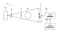
- FIG. 1 is a functional block diagram showing a configuration of an X-ray phase difference imaging apparatus according to the present invention.
- the X-ray source 3 according to the present invention includes an anode 3a that collides with electrons and a multi-slit 3b that allows X-rays emitted from the anode 3a to enter, and irradiates X-rays.
- the anode 3a is an electron target, and X-rays are generated when high-speed electrons collide. X-rays occur at a single focal point.
- the X-ray source 3 emits X-rays.
- the X-ray source 3 is configured to output X-rays having a specific wavelength.
- the subject M is placed between the phase grating 5 and the FPD 4. Alternatively, as shown in FIG. 36, the subject M may be placed between the multi slit 3b and the phase grating 5.
- the X-ray source 3 corresponds to the radiation source of the present invention.
- the FPD 4 corresponds to the detection unit of the present invention, and the phase grating 5 corresponds to the grating of the present invention.
- the fan-shaped X-ray beam emitted from the anode 3a enters the multi slit 3b.
- the multi slit 3b is made of a material such as gold that is easy to process, and has a thickness that does not allow X-rays to pass therethrough.
- the multi-slit 3b has a configuration in which slits extending in the vertical direction are arranged in the horizontal direction. Each of the slits is a through hole of the multi slit 3b.
- slits that transmit X-rays generated at a single generation point are arranged at a constant pitch in the orthogonal direction, which is a direction orthogonal to the extending direction of the slit, and the slit is not provided in a portion. Absorbs incident X-rays.
- the X-ray beam generated at the anode 3a passes through one of the slits provided in the multi slit 3b and exits from the multi slit 3b. At this time, each of the X-ray beams that have passed through the slits of the multi-slit 3b causes interference, and becomes a highly coherent X-ray beam toward the phase grating 5 (see FIG. 1).
- the left side of FIG. 2 shows the phase grating 5.
- the phase grating 5 has a plurality of absorption lines 5a extending linearly to absorb X-rays.
- the absorption lines 5a are arranged in the vertical direction at a predetermined pitch in a direction orthogonal to the extending direction (lateral direction).
- the X-ray beam emitted from the multi slit 3 b passes through the phase grating 5. At that time, part of the X-ray beam is absorbed by the phase grating 5.
- the X-ray beam emitted from the phase grating 5 reflects a pattern in which a plurality of bright lines remaining without being absorbed by the absorption line 5a are arranged.
- the pitch of the absorption lines 5a of the phase grating 5 is sufficiently small, interference occurs between the bright lines. Due to this interference, a blurred image like the image of the phase grating 5 is generated at a distance away from the phase grating 5 by the Talbot distance. It should be noted that this image is not a simple shadow of the phase grating 5 but an interference fringe caused by interference. Such an image is called a self-image.
- the X-rays emitted from the phase grating 5 are directed to the FPD 4 (see FIG. 1).
- the FPD 4 is configured to detect a self-image of the phase grating 5 caused by Talbot interference on the detection surface 4a that detects X-rays.
- the FPD 4 is, for example, a direct conversion type X-ray detector. That is, the direct conversion type FPD 4 has a conversion layer that converts X-rays into pairs of electrons and holes (charge carrier pairs). Carriers generated in the conversion layer are captured and accumulated in each of the detection elements 4p. When a signal for outputting a carrier is sent to the detection element 4p, the detection element 4p outputs the accumulated carrier as a detection signal.
- the fineness of the detection element 4p is the main factor that determines the spatial resolution of the FPD 4. As the detection element 4p is smaller, the spatial resolution of the FPD 4 is improved, and a finer structure can be detected.
- the conversion layer corresponds to the conversion unit of the present invention.
- the FPD 4 may be configured to detect fluorescence generated by X-rays instead of this configuration.
- the FPD 4 is configured to project the image of the phase grating 5 on the detection surface 4a in which the detection elements 4p for detecting X-rays are arranged vertically and horizontally to detect the image of the phase grating 5.
- the absorption grating 6 is provided so as to cover the detection surface 4 a on the FPD 4.
- the absorption grating 6 has a plurality of absorption lines 6a extending in a line shape that absorbs X-rays.
- the absorption lines 6a are arranged at a predetermined pitch in a direction orthogonal to the extending direction.
- the striped pattern of the absorption line 6a and the striped pattern of the phase grating 5 interfere with each other. This interference state is detected by the FPD 4.
- elongated absorption lines 6 a that absorb X-rays are arranged in a direction orthogonal to the direction in which the absorption lines 6 a extend.
- the direction in which the absorption line 6 a of the absorption grating 6 extends coincides with the direction in which the absorption line 5 a of the phase grating 5 extends.
- the absorption grating 6 corresponds to the second grating of the present invention.
- the absorption grating 6 is provided with a predetermined repeating pattern that absorbs X-rays.
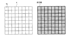
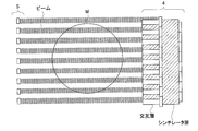
- the left side of FIG. 3 illustrates the configuration of the X-ray detection surface 4a of the FPD 4.
- the detection surface 4a of the FPD 4 has a shape such that a self-image of the phase grating 5 having a rectangular shape is reflected. Therefore, the detection surface 4 a of the FPD 4 has a rectangular structure like the phase grating 5.
- rectangular detection elements 4p are arranged vertically and horizontally. The direction in which the absorption line 5a of the phase grating 5 extends coincides with the longitudinal direction in which the detection elements 4p are arranged on the detection surface 4a of the FPD 4, and the direction in which the absorption line 5a of the phase grating 5 is arranged is FPD4.
- FIG. 3 shows a state in which the self-image of the phase grating 5 is reflected on the detection surface 4a.
- the detection element 4p on the detection surface 4a is drawn with a bold line.
- two dark lines constituting a self-image are captured in the single detection element 4p.
- This configuration is for convenience of explanation, and actually, four dark lines constituting a self-image appear in a single detection element 4p.
- the arrangement pitch in the vertical direction of the detection elements 4p is an integral multiple of the arrangement pitch of the dark lines of the self-image of the phase grating 5 appearing on the detection surface 4a.
- the arrangement pitch of the detection elements 4p is not necessarily an integral multiple of the arrangement pitch of the absorption lines 5a of the phase grating 5.
- the self-image of the phase grating 5 is larger than the phase grating 5. This is because the X-rays radiate from the X-ray source 3 so that the image of the phase grating 5 is enlarged and reflected on the detection surface 4a.
- the arrangement pitch of the absorption lines 5a of the phase grating 5 is set to be an integral multiple of the arrangement pitch of the dark lines of the self-image of the phase grating 5 appearing on the detection surface 4a.
- the self-image has a finer structure than the structure that can be captured by the detection element 4p. Therefore, it is supposed that a self image cannot be taken with this FPD4. However, it is possible to shoot a self-portrait by repeating the shooting many times. This point will be described later.
- the self-image according to the present invention has a characteristic configuration at the right end and the left end. However, this characteristic configuration is omitted on the right side of FIG. 3 for convenience of explanation. The configuration at both ends of the self-image will be described later.
- FIG. 4 shows a state in which the detection grating 4 is covered with the absorption grating 6.
- the detection element 4p on the detection surface 4a is drawn with emphasis by a bold line.
- two absorption lines 6a of the absorption grating 6 are reflected in the single detection element 4p.
- This configuration is for convenience of explanation, and actually, four absorption lines 6a are reflected in a single detection element 4p. That is, the arrangement pitch in the vertical direction of the detection elements 4p is an integral multiple of the arrangement pitch of the absorption lines 6a.
- the arrangement pitch of the self-images appearing on the detection surface 4a is the same as the arrangement pitch of the absorption lines 6a constituting the absorption grating 6.
- the absorption grating moving mechanism 15 illustrated in FIG. 1 will be described.
- the absorption grating moving mechanism 15 is configured to move the absorption grating 6 in the arrangement direction of the absorption lines 6a with respect to the detection surface 4a (vertical direction: a direction orthogonal to the direction in which the absorption lines 6a extend).
- the absorption lattice movement control unit 16 is provided for the purpose of controlling the absorption lattice movement mechanism 15.
- the absorption grating moving mechanism 15 is configured to change the positional relationship between the image of the phase grating 5 reflected on the detection surface and the absorption grating 6 in a direction orthogonal to one direction.
- the absorption grating moving mechanism 15 is provided for the purpose of changing the relative position between the absorption grating 6 and the self-image of the phase grating 5. Therefore, the absorption grating movement mechanism 15 and the absorption grating movement control unit 16 are specific means for changing the relative positions of the absorption grating 6 and the self-image of the phase grating 5.
- the absorption grating moving mechanism 15 corresponds to a relative position changing unit of the present invention.
- the relative position can be changed.
- the relative position can be changed by moving the anode 3a in the arrangement direction (vertical direction) of the absorption lines 6a, and by moving the multi slit 3b in the arrangement direction (vertical direction) of the absorption lines 6a.
- the relative position can be changed.
- the relative position can also be changed by moving the phase grating 5 in the arrangement direction of the absorption lines 6a.
- a moving mechanism (a source moving mechanism, a multi-slit moving mechanism, a phase grating moving mechanism) that moves each part to be moved is provided instead of the absorption grating moving mechanism 15.
- a control unit (a radiation source movement control unit, a multi-slit movement control unit, and a phase grating movement control unit) that controls the moving mechanism is provided instead of the absorption grating movement control unit 16.
- a control unit a radiation source movement control unit, a multi-slit movement control unit, and a phase grating movement control unit
- the moving mechanism is provided instead of the absorption grating movement control unit 16.
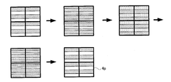
- FIG. 5 shows how the absorption grating 6 is moved by the absorption grating moving mechanism 15.
- FIG. 5 shows one range in which the detection elements 4p are arranged in 2 ⁇ 2 on the detection surface. Therefore, there are four absorption lines 6a of the absorption grating 6 in this range.
- the absorption line 6 a and the dark line constituting the self-image of the phase grating 5 are just overlapped. In this state, X-rays can pass through the gap between the absorption lines 6a adjacent to each other.
- the absorption grating 6 When the absorption grating 6 is moved from this state, the dark line of the self image starts to overlap with the absorption line 6a again. As a result, the area of the dark region where the X-rays do not hit is reduced on the detection element 4p. When the absorption grating 6 is further moved thereafter, the state returns to a state where the absorption lines 6a and the dark lines constituting the self-image of the phase grating 5 are just overlapped.
- FIG. 6 shows an interference image (interference image) obtained when the state in which the self-image of the phase grating 5 interferes with the absorption grating 6 while moving the absorption grating 6 in the arrangement direction of the absorption lines 6a.
- the arrangement pitch of the absorption lines 6a constituting the absorption grating 6 and the arrangement pitch of the dark lines constituting the self-image of the phase grating 5 are the same, and the arrangement pitch of the detection elements 4p is obtained by multiplying the arrangement pitch by an integer. Therefore, no moiré occurs between the phase grating 5 and the array of detection elements 4p, and no moiré occurs between the absorption grating 6 and the array of detection elements 4p. Therefore, no interference fringes appear in any interference image.
- the absorption grating moving mechanism 15 that realizes such movement of the absorption grating 6.
- the absorption grating moving mechanism 15 moves the absorption grating 6 by at least the arrangement pitch of the absorption lines 6 a of the absorption grating 6. Intermittent images are continuously shot during that time.
- the number of interference images to be photographed is, for example, eight. As shown in FIG. 6, nine interference images may be taken.
- the self-image generating unit 12 is configured to calculate the original self-image based on a series of interference images continuously shot while changing the relative positions of the absorption grating 6 and the phase grating 5 as shown in FIG. It is.
- the self-image generating unit 12 of the present invention is configured to accurately reproduce the self-image by taking into account how much the relative position between the absorption grating 6 and the self-image of the phase grating 5 is deviated from the ideal. The point will be described.
- the self-image generation unit 12 corresponds to the lattice image generation unit of the present invention.
- FIG. 8 shows a change in the relative position of the self-images of the absorption grating 6 and the phase grating 5 related to actual interference image continuous shooting.
- the self-image generation unit 12 cannot accurately generate the original self-image based on such an interference image that cannot be continuously shot as ideal.
- the self-image reflected on the detection surface 4a is disturbed by the influence of the subject M.
- the interference image further includes the influence of the positional deviation between the self-images of the absorption grating 6 and the phase grating 5 in this disturbance, the original self-image is grasped. It becomes quite difficult.
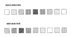
- FIG. 9 explains the circumstances.
- the upper part of FIG. 9 is an interference image obtained when continuous shooting is performed while moving the absorption grating 6 and represents an ideal transition of the interference image.
- the lower part of FIG. 9 is an interference image obtained when continuous shooting is executed while actually moving the absorption grating 6. Comparing the top and bottom of FIG. 9, it can be seen that the timing at which the darkest interference image appears is different. This difference in timing represents how much the self-images of the absorption grating 6 and the phase grating 5 deviate from ideal.
- the absorption grating 6 is included in the self-image pattern. It is likely that only information relating to the pattern of the self-image can be extracted from a series of interference images in which the influence of the positional deviation between 6 and the self-image of the phase grating 5 is superimposed. However, it is not so easy in practice.
- the interference image 6 is continuously shot while the absorption grating 6 is moved without the subject M, and the positions of the absorption grating 6 and the self-image of the phase grating 5 are determined based on the series of interference images. The deviation is calculated. If the positional deviation is actually measured in advance in this manner, a self-image disturbed by the influence of the subject M can be accurately acquired based on a series of interference images continuously taken with the subject M being captured.
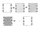
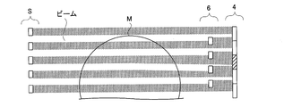
- FIG. 10 illustrates the phase grating 5 described on the left side of FIG. 2 in more detail. That is, when the extending direction of the absorption line 5 a in the phase grating 5 is recognized as the lateral direction of the phase grating 5, the arrangement pitch of the absorption lines 5 a at the left end and the right end of the phase grating 5 is the absorption line in the center of the phase grating 5. This is different from the arrangement pitch of 5a. As can be seen from FIG. 10, the direction in which the absorption line 5a extends is the horizontal direction in both end regions and the same horizontal direction in the central region.
- the absorption line 5a at the left end of the phase grating 5 and the absorption line 5a at the center are not continuous with each other, and are arranged vertically in the array and the center of the absorption lines 5a arranged vertically in the left end.
- a gap that does not have the absorption line 5a is provided between the absorption line 5a and the array.
- the absorption line 5a at the right end of the phase grating 5 and the absorption line 5a at the center are not continuous with each other, and are arranged vertically in the arrangement and the center of the absorption lines 5a arranged vertically in the right end.
- a gap that does not have the absorption line 5a is provided between the arranged absorption lines 5a.
- the central portion corresponds to the subject area of the present invention, and both ends correspond to the reference region of the present invention.
- the phase grating 5 is an area in which a predetermined repetitive pattern for absorbing X-rays is provided and an object area through which an X-ray beam passing through the object passes is different from the object area. And a reference region which is a region where the pattern is provided. The arrangement pitch of the pattern repeated in the subject area is different from the arrangement pitch of the pattern repeated in the reference area.
- the phase grating 5 is an area where absorption lines 5a extending in one direction that absorb X-rays are arranged in a direction perpendicular to one direction, and an X-ray beam that passes through the subject M passes therethrough.
- the central portion is provided with an end portion through which an X-ray beam that does not pass through the subject M passes, and the central portion is an area arranged so that the arrangement pitch of the absorption lines 5a is different. That is, the arrangement pitch in the vertical direction of the detection elements 4p is not an integral multiple of the arrangement pitch of the dark lines that appear at both ends of the self-image of the phase grating 5.
- the self-image of the phase grating 5 is larger than the phase grating 5. This is because the X-rays radiate from the X-ray source 3 so that the image of the phase grating 5 is enlarged and reflected on the detection surface 4a.
- the arrangement pitch of the absorption lines 5a of the phase grating 5 is set so as not to be an integral multiple of the arrangement pitch of the dark lines of the self-images of the phase grating 5 appearing on the detection surface 4a, and the detection element 4p has the absorption lines 5a. It does not mean that it is not an integral multiple of the arrangement pitch.
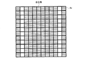
- FIG. 11 shows a state where the self-image of the phase grating 5 is reflected on the detection surface 4a, and this time also includes the edge of the self-image of the phase grating 5.
- the detection element 4p on the detection surface 4a is drawn with emphasis by a bold line.
- the detection element 4p is divided into four lines for each of the detection elements 4p positioned on the detection surface 4a where the central portion of the self-image is projected. One dark line appears, and one dark line appears on the third stage. All of the detection elements 4p in the central portion have self-image dark lines appearing in this pattern.
- the dark lines of the self image are not reflected in the same pattern on each of the detection elements 4p positioned at the portions where both ends of the self image are projected.
- the position and the number of the self-image dark line appear vary depending on each detection element 4p.
- the reason for the change in the dark line pattern reflected on the detection element 4p at both ends of the self-image is that the arrangement of the absorption lines 5a arranged at both ends of the self-image is devised.
- the arrangement pitch of the dark lines constituting the self-image of the phase grating 5 on the detection surface 4a is different between the central portion and both end portions of the self-image.
- the arrangement pitch of the dark lines at both ends of the self image is shorter than the arrangement pitch of the dark lines at the center of the self image. Therefore, the position and the number of dark lines appearing on the detection elements 4p are not constant among the detection elements 4p.
- sequence pitch concerning both ends is shorter than the arrangement
- the arrangement pitch related to both ends may be longer than the arrangement pitch related to the center.
- the arrangement pitch of the dark lines at both ends of the phase grating 5 is not an integral multiple of the arrangement pitch of the detection elements 4p4a and the arrangement pitch of the absorption lines 6a of the absorption grating 6a.
- the positions and the number of dark lines appearing on the detection elements 4p are all the detection elements 4p. It is not different. Focusing on a certain detection element 4p, using the dark line appearance pattern on the detection element 4p as a reference pattern and looking at each detection element 4p arranged in the vertical direction of the detection element 4p, the dark line appearance pattern Gradually changes from the standard pattern. Then, after reaching a certain pattern, it approaches the reference pattern again and returns to the reference pattern. Thereafter, this pattern change is repeated.
- the detection elements 4p having the same number of dark line positions appearing on the detection element 4p appear at equal intervals.
- the detection elements 4p having the same appearance pattern of dark lines are at positions separated by, for example, 20 pieces in the vertical direction.
- the subject M in the X-ray phase contrast imaging apparatus of the present invention is configured to be reflected in the center of the self-image of the phase grating 5. Therefore, both ends of the self-image of the phase grating 5 are a result of X-rays not passing through the subject M being imaged, and the self-image is not disturbed by the influence of the subject M.
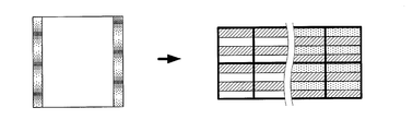
- FIG. 12 shows how the self-image of the phase grating 5 interferes with the absorption grating 6 at both ends of the self-image.
- the arrangement pitch of the dark lines in the self-image of the phase grating 5 and the arrangement pitch of the absorption lines 6a in the absorption grating 6 coincide on the detection surface 4a of the FPD 4, It was an explanation that interference fringes do not occur with the absorption grating 6. This description is about the center of the self-image. In fact, at both ends of the self-image, the absorption grating 6 and the self-image interfere with each other to generate interference fringes as shown on the right side of FIG.
- the arrangement pitch of the self-image of the phase grating 5 is shorter than the arrangement pitch of the absorption lines 6a of the absorption grating 6 at both ends of the self-image.
- the arrangement pitch of the dark lines at both ends of the phase grating 5 is not an integral multiple of the arrangement pitch of the absorption lines 6 a of the absorption grating 6. Therefore, the positions of the dark lines of the self-image that appear in the vicinity of each of the absorption lines 6a at both ends of the self-image are not constant between the absorption lines 6a.
- the positions of the dark lines appearing in the vicinity of the absorption lines 6a are all the absorption lines 6a. It is not different. For example, paying attention to the absorption line 6a that just overlaps the dark line of the self-image and looking at each absorption line 6a arranged in the vertical direction of the absorption line 6a, the dark line gradually shifts from the absorption line 6a. Go. Then, after reaching a state where the absorption line 6a and the dark line do not overlap, the absorption line 6a again overlaps the dark line, and the dark line again overlaps the absorption line 6a again. Thereafter, this change is repeated.
- the arrangement pitch of the detection elements 4p is twice the arrangement pitch of the absorption lines 6a
- the dark lines of the self image overlap every 40 absorption lines 6a arranged in the vertical direction.
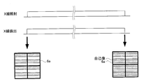
- FIG. 13 shows the interference image obtained when the self-image of the phase grating 5 interferes with the absorption grating 6 while moving the absorption grating 6 in the arrangement direction of the absorption lines 6a.
- FIG. 4 is a diagram including an end portion of the self-image of the phase grating 5. In any interference image, interference fringes appear at both ends. The central part of the self-image of the phase grating 5 is reflected in the central part of the interference image. The fact that no interference fringes appear in this portion has already been described with reference to FIG. Both ends of the self-image of the phase grating 5 are reflected at both ends of the interference image. The interference fringes appearing in this portion has already been described with reference to FIG.
- interference fringes generated by interference between the self-image of the phase grating 5 and the absorption grating 6 are reflected at both ends of each interference image.
- the interference fringes are configured by alternately arranging bright bright portions and dark dark portions.
- the bright part of the interference fringe is located at the upper end of the interference image.
- the bright part gradually moves to the lower side of the interference image.
- the upper end of the interference image returns to the bright portion again.
- Such movement of the interference fringes is caused by the relative movement of the self-images of the absorption grating 6 and the phase grating 5 described in FIG.
- the absorption line 6a of the absorption grating 6 and the dark line of the self-image are just overlapped.
- the absorption grating 6 is moved with respect to the self-image, the place where the absorption line 6a and the dark line of the self-image just overlap moves to the lower side of the self-image. Then, the bright part in the interference fringe on the interference image also follows and moves downward.
- the left side of FIG. 14 shows a state where bright portions of interference fringes appear at the upper end of the interference image at both ends of the interference image.
- the absorption line 6a of the absorption grating 6 and the dark line of the phase grating 5 are just overlapped as illustrated.
- the right side of FIG. 14 shows a state where the bright portions of the interference fringes appear at positions slightly shifted downward from the upper end of the interference image at both ends of the interference image.
- the absorption line 6 a of the absorption grating 6 and the dark line of the phase grating 5 are slightly shifted from the state where they overlap each other.
- the left side of FIG. 15 shows a state in which the bright portions of the interference fringes are further shifted downward from the state of the right side of FIG. 14 at both ends of the interference image.
- the absorption line 6 a of the absorption grating 6 and the dark line of the phase grating 5 are further shifted as illustrated.
- the right side of FIG. 15 shows a state where the bright portions of the interference fringes appear at positions further shifted to the lower side of the interference image at both ends of the interference image.
- the absorption line 6 a of the absorption grating 6 and the dark line of the phase grating 5 do not overlap as shown in the figure.
- the position calculation unit 11 in FIG. 1 detects the relative position of the self-image of the phase grating 5 with respect to the absorption grating 6 based on such a principle. Interference fringes unique to the interference image are captured at both ends of the continuously captured interference image. Therefore, the position calculation unit 11 can detect the relative position of the self-image of the phase grating 5 with respect to the absorption grating 6 for each interference image.
- the position calculation unit 11 is based on the difference in the detected amount of X-rays between the detection elements 4p located in the region where both ends of the phase grating 5 on the detection surface 4a are reflected, and the phase grating 5 and the absorption grating 6 The relative position of is calculated.
- the position calculation unit 11 detects the moire (interference fringes) generated between the pattern image of the reference region that appears on the detection surface and the pattern on the absorption grating, and calculates the relative position between the phase grating 5 and the absorption grating 6. To do. At this time, the position calculation unit 11 also calculates the position of the X-ray source 3 with respect to the phase grating 5 and the absorption grating 6. This is because the appearance of the interference fringes varies depending on the relative positions of the three members of the X-ray source 3, the phase grating 5, and the absorption grating 6.
- the detection result regarding the relative position of the self-image of the phase grating 5 with respect to the absorption grating 6 detected by the position calculation unit 11 is sent to the self-image generation unit 12 together with the interference image.
- the self-image generation unit 12 corrects the calculation related to the self-image generation based on the detection result of the relative position corresponding to the interference image, generates a self-image of the phase grating 5, and a self-image including the self-image. Generate an image.
- the self-image generating unit 12 is based on the image of the phase grating 5 obtained by continuous shooting while changing the positional relationship between the image of the phase grating 5 and the absorption grating 6 and the image obtained by superposing the absorption grating 6. Is generated.
- the self-image generation unit 12 according to the present invention is characterized in that, in particular, when generating an image of the phase grating 5 based on the output of the FPD 4, correction is performed with reference to the calculated relative position.
- the generated self-image is sent to the fluoroscopic image generator 13.
- the fluoroscopic image generation unit 13 generates a fluoroscopic image in which the phase difference distribution inside the subject M is imaged based on the self-image. Based on this operation, the operation of the X-ray phase contrast imaging apparatus of the present invention is completed.
- the left end of the central portion of the self-image of the phase grating 5 is in a state where the absorption line 6a just overlaps the self-image as shown in FIG.
- the interference fringes appearing on the right side of the interference image in FIG. 16 are actually the same as the interference fringes described on the right side in FIG. Accordingly, the right end of the center portion of the self-image of the phase grating 5 is in a state where the absorption line 6a does not overlap the self-image as shown in FIG.
- the positional relationship between the absorption grating 6 and the self-image of the phase grating 5 at the right end of the center of the phase grating 5 and the phase grating 5 It is possible to individually obtain the positional relationship between the absorption grating 6 and the self-image of the phase grating 5 at the left end of the central portion. By measuring these two positional relationships, it can be seen how much the self-image of the phase grating 5 is inclined with respect to the absorption grating 6.
- the position calculation unit 11 calculates the inclination state of the self-image. If it is found that the self-image is tilted too much, for example, by rotating the phase grating 5, the tilt of the self-image of the phase grating 5 can be corrected and the continuous operation of interference images can be continued. .
- the subject rotation mechanism 17 is provided for the purpose of rotating the subject M with respect to the respective parts 3, 4, 5, and 6.
- the subject rotation control unit 18 is provided for the purpose of controlling the subject rotation mechanism 17.
- ⁇ Tomographic image generator> A plurality of fluoroscopic images generated while rotating the subject M are sent to the tomographic image generation unit 14.
- the tomographic image generation unit 14 reconstructs a plurality of fluoroscopic images and generates a tomographic image of the subject M to which the phase difference distribution of the subject M is mapped.
- the self-image In order to generate a single fluoroscopic image, the self-image must be captured a plurality of times. Therefore, to acquire a tomographic image, a considerable number of self-images must be taken. As described above, the self-image of the phase grating 5 moves little by little on the detection surface 4a due to thermal expansion of the portion that fixes the phase grating 5 while the self-image capturing is repeated.
- the present invention even if such a situation occurs, the positional relationship between the self-image and the absorption grating 6 can be measured every time the self-image is taken, so that the tomographic image can be obtained without being affected by the movement of the self-image. Can be generated.
- the present invention can also perform CT imaging of the subject M.
- the units 11, 12, 13, 14, 16, and 18 according to the present invention are realized by the CPU of the apparatus executing various programs. Instead of the CPU, each unit may be realized by an individual microcomputer.
- the apparatus of the present invention is provided with the phase grating 5 provided with the central portion and both end portions.
- the lattice absorbers are arranged in any region, the arrangement pitch is different.
- the image (grating image) of the phase grating 5 connected on the detection surface interferes with the absorption grating 6 provided so as to cover the detection surface. In photographing by the fringe scanning method and the edge illumination method, no interference fringes occur in the portion where the center portion of the detection surface appears. Therefore, when the subject M is not placed, X-ray detection is performed between the detection elements 4p. There is no difference in quantity.
- the self-image of the phase grating 5 interferes with the absorption grating 6 to generate interference fringes.
- the appearance position of this interference fringe represents the relative position between the self-image and the absorption grating 6 on the detection surface.
- Both end portions of the phase grating 5 are reflected in the captured interference image, and the center portion of the phase grating 5 is located in a portion different from that in the interference image. Therefore, according to the present invention, in order to know the relative positions of the phase grating 5 and the absorption grating 6, it is not necessary to separately perform shooting without the subject M. This is because the interference image includes interference fringes representing the relative positions of the self-image and the absorption grating 6 in addition to the region where the subject M is reflected.
- phase grating 5 If the reference regions are provided at both ends of the phase grating 5, not only the positional deviation between the phase grating 5 and the absorption grating 6 but also the rotation angle of the absorption grating 6 with respect to the phase grating 5 can be calculated. Similarly, not only the positional deviation between the phase grating 5 and the FPD 4 but also the rotation angle of the phase grating 5 and the FPD 4 can be calculated.
- the present invention is not limited to the above-described configuration, and can be modified as follows.
- the absorption grating 6 is moved with respect to the FPD 4.
- the present invention is not limited to this configuration.
- the present invention may be applied to an X-ray phase contrast imaging apparatus in which the absorption grating 6 is fixed to the FPD 4.
- FIG. 17 shows an attempt to image an X-ray phase difference by a method called a moire single-shot method.
- FIG. 18 shows the phase grating 5 according to this modification.
- the phase grating 5 according to the present modification is also provided with a central portion that transmits the X-ray beam transmitted by the subject M and both end portions that allow the X-ray beam that does not pass through the subject M to pass.
- the configuration for both ends is the same as that of the phase grating 5 of the first embodiment.
- the absorption line 5 a of the phase grating 5 is inclined with respect to the direction in which the absorption line 6 a of the absorption grating 6 extends.
- the arrangement pitch of the absorption lines 5a of the phase grating 5 is the same as the arrangement pitch of the absorption lines 6a.
- the direction of arrangement differs between the absorption line 6a and the absorption line 5a at the center of the phase grating 5.
- the direction in which the grating absorber extends at the center of the phase grating 5 is inclined from the direction in which the grating absorber extends at both ends of the phase grating 5, and the direction in which the absorption line 6 a extends in the absorption grating 6. It coincides with the direction in which the grating absorber extends at both ends of the phase grating 5.
- the self-image of the phase grating 5 can be imaged without moving the absorption grating 6 with respect to the FPD 4.
- interference fringes are generated between the absorption grating 6 and the phase grating 5. This interference fringe is for the self-image related to the central portion of the phase grating 5 and is different from the interference fringe for the self-image at the end of the phase grating 5 described with reference to FIG.
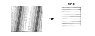
- FIG. 19 an interference image in which interference fringes spread over one surface is obtained as shown in FIG.
- the interference image obtained in FIG. 19 is actually a single sheet formed by combining a plurality of interference images having different relative positions between the self-image of the phase grating 5 and the absorption grating 6 described in FIG. It can be regarded as an interference image. Therefore, the self-image generation unit 12 can generate a self-image based on the interference fringe interference image obtained in FIG. Even in this modification, the self-image cannot be generated correctly unless the relative position between the self-image of the phase grating 5 and the absorption grating 6 is accurately known.
- the device since the device is devised so that interference fringes are generated at both ends of the self-image of the phase grating 5, the self-image of the phase grating 5 and the absorption grating 6 are based on the appearance positions of the interference fringes.
- the relative position of can be accurately known.
- the present invention can be applied to the apparatus related to the moire single-shot method as described above.
- the moire single-photographing method interference fringes are also generated at the center, and it is not impossible in principle to know the relative position between the absorption grating 6 and the grating image using this.
- the interference fringes appearing at the center of the self-image of the phase grating in the moire single-shot method are too fine for pitching and are not suitable for knowing the relative position between the absorption grating 6 and the grating image.
- both ends of which the pitch of the grating absorber is adjusted so as to generate an interference fringe pattern suitable for knowing the relative position are provided separately from the central portion, so that the grating can be accurately
- the positional relationship between the image and the absorption grating 6 can be known.
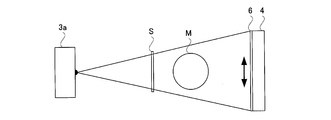
- FIG. 20 shows an apparatus configuration relating to the edge illumination imaging apparatus.
- the multi slit 3b is not provided, and the shadow of the grating S is reflected in the FPD 4.
- the grating S is provided in place of the phase grating 5 in the first embodiment, and has the same configuration as the phase grating 5 described with reference to FIG.
- the phase grating in the first embodiment is a term used when describing Talbot interference.
- Talbot interference since Talbot interference is not used, it is simply referred to as a grating S.
- the arrangement pitch of the absorption lines in the grating S is wider than the arrangement pitch of the absorption lines 5 a in the phase grating 5.
- FIG. 21 shows the configuration of the detection surface of the FPD 4 and the absorption grating 6 in this modification.
- the detection surface 4a of the FPD 4 is configured by the detection elements 4p being arranged vertically and horizontally.
- the absorption line 6a of the absorption grating 6 extends in the lateral direction of the detection surface 4a as in the first embodiment. They are arranged in the longitudinal direction of the detection surface 4a.
- the gap in the vertical direction of the adjacent absorption lines 6a is half the width of the detection elements 4p, and the width of the absorption lines 6a in the arrangement direction is half of the detection elements 4p.
- the absorption lines 6a are arranged in the vertical direction at an arrangement pitch corresponding to 4p1 detection elements.
- the absorption grating 6 is aligned with the FPD 4 so that the absorption lines 6a are positioned so as to straddle the adjacent detection elements 4p.
- the edge illumination imaging apparatus is configured to generate an interference image related to the internal structure of the subject M by repeating photographing twice. This point will be briefly described.
- FIG. 22 shows the first of the two shootings.
- the X-rays that have passed through the grating S pass through the subject M as a stripe beam and enter the absorption grating 6.
- the striped beam is formed by arranging X-ray beams that pass through the slits and have an elongated shape and half the width of the detection element 4p having the width of FPD4.
- the absorption grating 6 is disposed at a position where the lower half of each of the elongated X-ray beams is incident on the absorption line 6a. Therefore, the lower half of each of the elongated X-ray beams is absorbed and becomes narrower. Is incident on the FPD 4.
- This further narrowed X-ray beam is incident on a certain detection element 4p.
- the X-ray beam is configured to enter the central portion of the detection element 4p.
- the detection element 4p on which the X-ray beam is incident will be referred to as an incident target detection element 4p.
- the X-ray beam When the subject M is not placed between the grating S and the absorption grating 6, the X-ray beam only enters the center of the detection element 4p. However, when the subject M is placed between the grating S and the absorption grating 6, the traveling direction changes while the X-ray beam passes through the subject M. As shown in FIG. 23, when the elongated X-ray beam bends downward, the X-ray beam tends to enter while being shifted downward in the target detection element 4p. However, the X-ray beam is blocked by the absorption line 6a of the absorption grating 6, and does not reach the incident target detection element 4p indicated by oblique lines. It is possible to know how much the X-ray beam is bent downward by the output of the detection element 4p as the incident target. Based on such a principle, the edge illumination imaging apparatus captures an interference image indicating the degree to which the X-ray is bent downward.
- the FPD 4 and the absorption grating 6 are moved upward by half the detection element 4p with respect to the striped X-ray beam. By this operation, the positional relationship between the striped beam and the absorption grating 6 changes.
- FIG. 24 shows the second of the two shootings.
- the X-rays that have passed through the grating S pass through the subject M as a stripe beam and enter the absorption grating 6.
- the striped beam is configured by arranging X-ray beams that pass through slits and have an elongated shape.
- the absorption grating 6 is disposed at a position where the upper half of each of the elongated X-ray beams is incident on the absorption line 6a. Therefore, each of the elongated X-ray beams is absorbed at the upper half and becomes narrower. Is incident on the FPD 4. This further narrowed X-ray beam is incident on a certain detection element 4p. At this time, the X-ray beam is configured to enter the central portion of the detection element 4p.
- the detection element 4p on which the X-ray beam is incident will be referred to as an incident target detection element 4p.
- the X-ray beam When the subject M is not placed between the grating S and the absorption grating 6, the X-ray beam only enters the lower half of the detection element 4p. However, when the subject M is placed between the grating S and the absorption grating 6, the traveling direction changes while the X-ray beam passes through the subject M. As shown in FIG. 25, when the elongated X-ray beam bends downward as indicated by the arrow, the X-ray beam tends to be incident on the incident target detection element 4p with an upward shift. However, the X-ray beam is blocked by the absorption line 6a of the absorption grating 6, and does not reach the incident target detection element 4p indicated by oblique lines. It is possible to know how much the X-ray beam is bent upward by the output of the detection element 4p as the incident target. Based on such a principle, the edge illumination imaging apparatus captures an interference image indicating the degree to which the X-ray is bent upward.
- the edge illumination imaging apparatus generates an interference image in which a change in the X-ray traveling direction by the subject M is imaged based on the two captured interference images.
- the interference fringes indicating the shadow of the grating S and the relative position of the absorption grating 6 appear at both ends of the interference image (see FIG. 12). According to the apparatus of the present invention, even if the relative position of the shadow of the grating S and the absorption grating 6 is not ideal, it is not affected by that and accurate imaging of the inside of the subject M is possible.
- the principle of the present invention can also be applied to an edge illumination imaging apparatus having a configuration in which the absorption grating 6 is not provided.
- the apparatus according to this modification includes an X-ray detector having a scintillator that generates fluorescence when X-rays enter.
- detection elements are arranged in a two-dimensional matrix. This detection element is configured to detect fluorescence generated in the scintillator.
- Such an X-ray detector is called an indirect detector.
- a layer formed by arranging detection elements will be referred to as a two-dimensional matrix layer.
- FIG. 26 shows a state in which edge illumination imaging is performed using the X-ray detector of this modification.
- the FPD 4 in this modification has alternating layers configured by alternately arranging scintillator elements C having half the width of the detecting elements 4p and glass elements G having half the width of the detecting elements 4p.
- the scintillator element is made of a material that emits fluorescence when X-rays enter, and the glass element G is made of glass that does not emit fluorescence even when X-rays enter.
- the alternating layers are aligned with the two-dimensional matrix layer so that the scintillator elements straddle the adjacent detection elements 4p.
- the configuration in FIG. 26 can be taken in the same manner as in FIG. That is, in the detection element 4p of FIG. 22, the part where the absorption line 6a of the absorption grating 6 is provided corresponds to the part where the glass elements G of alternating layers are provided in the detection element 4p of FIG. Further, in the detection element 4p in FIG. 22, the portion exposed from the absorption line 6a corresponds to the portion in which the scintillator elements C of the alternating layers are provided in the detection element 4p in FIG. Therefore, if the configuration of FIG. 26 is used, an interference image showing the degree to which the X-ray is bent downward can be taken.
- the configuration of this modification is also configured to capture the interference image twice. After the imaging according to FIG. 26 is completed, the FPD 4 is moved upward by a half of the detection element 4p with respect to the stripe-shaped X-ray beam before the subsequent second imaging is performed. By this operation, the positional relationship between the striped beam and the FPD 4 is changed as shown in FIG.
- FIG. 28 illustrates a configuration for moving the FPD 4.
- the FPD movement mechanism 15a is configured to move the FPD 4, and the FPD movement control unit 16a is configured to control the FPD movement mechanism 15a.
- the FPD moving mechanism 15 a is provided for the purpose of changing the relative position between the self-image of the phase grating 5 and the FPD 4.
- the change of the relative position is the same as that of the first embodiment in that it can be realized by moving the X-ray source 3, the multi slit 3b, and the phase grating 5.
- the part where the absorption line 6a of the absorption grating 6 is provided corresponds to the part where the glass elements G of alternating layers are provided in the detection element 4p of FIG.
- the part exposed from the absorption line 6a corresponds to the part in which the scintillator elements C of the alternating layers are provided in the detection element 4p of FIG. Therefore, if the configuration of FIG. 27 is used, an interference image showing the degree to which the X-ray is bent upward can be taken.
- the present invention can also be applied to a configuration in which the above modification (3) is further developed and two interference images are taken at a time.
- the FPD 4 according to this modification is provided with a scintillator layer composed only of a scintillator and another two-dimensional matrix layer in the alternating layers and the two-dimensional matrix layer described in FIG. .
- the two-dimensional matrix layer provided with the scintillator layer interposed therebetween is aligned so that the mutual detection elements are shifted by half of the detection elements. 26 is performed by the two-dimensional matrix layer located on the left side of the scintillator layer, and the interference image according to FIG. 27 is captured by the two-dimensional matrix layer located on the right side of the scintillator layer.
- the absorption grating 6 is moved with respect to the FPD 4.
- the present invention is not limited to this configuration.
- the present invention may be applied to an X-ray phase difference imaging apparatus having a configuration in which the absorption grating 6 is omitted.
- Detecting elements 4p are arranged vertically and horizontally on the detection surface of the FPD 4 according to the modification as shown in FIG. Since the detection element 4p is sufficiently fine, the width of the dark line of the self image is approximately the same as the width of the detection element 4p. The arrangement pitch of the detection elements 4p on the detection surface is smaller than the arrangement pitch of the lattice absorber images on the detection surface.
- the detection element 4p may be finely configured so that the width of the dark line of the self-image is wider than the width of the detection element 4p.
- FIG. 32 shows how the arrangement of the detection elements 4p interferes with the self-image of the phase grating 5 at both ends of the detection surface at the end of the FPD 4.
- the arrangement pitch of the dark lines constituting the self image is an integral multiple of the width of the detection element 4 p, the self image is only detected as it is on the detection surface.
- the arrangement pitch of the dark lines constituting the self-image is not an integral multiple of the width of the detection element 4p at both ends of the FPD 4, the detection element 4p arrangement and the self-image of the phase grating 5 interfere at this portion. .
- the dark line of the self image just overlaps the detection element 4p.
- a dark line of a self-image is superimposed for every four detection elements 4p.
- the dark lines that have just overlapped the detection element 4p on the upper side are also detected elements 4p, 8 that are separated from the detection element 4p by four. If the detection elements 4p separated from each other, the detection elements 4p separated from each other by 12 and the detection elements 4p separated from each other by 16 are viewed in order, the dark line gradually shifts from the detection element 4p toward the lower side.
- the position calculation unit 11 is based on the difference in the detected amount of X-rays between the detection elements 4p located in the region where both ends of the phase grating 5 on the detection surface are reflected. And the relative position of the FPD 4 is calculated.
- the position calculation unit 11 calculates the relative position between the phase grating 5 and the FPD 4 by detecting moire (interference fringes) generated between the pattern image of the reference region appearing on the detection surface and the pattern on the absorption grating.
- the position calculation unit 11 also calculates the position of the X-ray source 3 with respect to the phase grating 5 and the FPD 4. This is because the appearance of the interference fringes changes depending on the relative positions of the three members of the X-ray source 3, the phase grating 5, and the FPD4.
- the deviation between the detection element 4p and the dark line can be observed by a change in the X-ray dose detected by the detection element 4p. That is, since the dark line of the self image just overlaps the detection element 4p at the upper end position, almost no X-ray is detected. As the outputs of the detection element 4p, the detection element 4p, the separation element 4p, the separation element 4p, the separation element 4p, and the detection element 4p, which are separated from each other, are detected in order. To come. This is because the overlap of dark lines is gradually eliminated.
- the relative position between the array of detection elements 4p and the self-image of the phase grating 5 can be calculated based on the difference in the detected amount of X-rays.
- the calculated relative position can be used to correct the captured self-image. That is, the photographed self-image is disturbed because the relative position between the arrangement of the detection elements 4p and the self-image of the phase grating 5 is not ideal. If the relative position can be measured accurately, this disturbance can be removed by correction.
- the present invention can be applied to apparatuses other than the apparatus provided with the absorption grating 6. That is, the detection elements 4p having a predetermined size are arranged vertically and horizontally on the detection surface. Accordingly, the FPD 4 generates an interference image by discretely sampling X-rays. Therefore, interference may occur between the array of the detection elements 4p and the lattice image on the detection surface. Based on such a principle, interference fringes are generated in the portion of the interference image output from the FPD 4 where the reference region of the phase grating 5 is reflected. This interference fringe represents the relative position between the phase grating 5 and the FPD 4.
- Both end portions of the phase grating 5 are reflected in the captured interference image, and the center portion of the phase grating 5 is located in a portion different from that in the interference image. Therefore, according to the present invention, it is not necessary to separately perform shooting without the subject M in order to know the relative position of the phase grating 5 and the FPD 4. This is because the interference image includes interference fringes representing the relative position of the lattice image and the FPD 4 in addition to the region where the subject M is reflected.
- the interference image is captured by one shot, but the present invention is not limited to this configuration.
- a plurality of images may be continuously shot and added to generate an interference image.
- FIG. 33 illustrates a method for capturing an interference image in the first embodiment.
- X-ray detection is continuously performed during one X-ray irradiation, and the detection data accumulated in the FPD 4 is read after the X-ray irradiation ends.
- an imaging method only one image is obtained during one X-ray irradiation.
- An error may occur when the position of the phase grating 5 is shifted or the radiation generation point of the radiation source 3 is shifted from the ideal position due to thermal expansion or vibration of the optical system during imaging. . That is, as shown in FIG.
- the absorption line 6a of the absorption grating 6 and the self-image of the phase grating 5 are in a state of being overlapped with each other.
- the relative position of the phase grating 5 and the absorption grating 6 gradually changes, and the positions of the self-images of the absorption line 6a and the phase grating 5 are also shifted accordingly.
- the configuration of the first embodiment does not consider such circumstances, and generates an interference image on the assumption that the relative positions of the phase grating 5 and the absorption grating 6 have not changed from the start of imaging.
- FIG. 34 illustrates the configuration of this modification.
- the FPD 4 is read many times during one radiography, and a plurality of images are generated based on the result.
- the image generated at this time is an image in which the interference image is underexposed, and is referred to as an instantaneous interference image. Pay attention to the edge of the instantaneous interference image.
- Interference fringes formed by interference between the self-images of the absorption grating 6 and the phase grating 5 are reflected at the edge of the image.
- the interference fringes at the start of imaging indicate that the absorption line 6a of the absorption grating 6 and the dark line of the self-image of the phase grating 5 are exactly overlapped as described on the left side of FIG.
- the interference fringes appearing at the ends of the instantaneous interference images that are continuously shot change gradually.
- the relative position of the absorption grating 6 and the phase grating 5 changed due to the influence of thermal expansion of the optical system during photographing.
- the interference image of this modification is generated by adding only the instantaneous interference images captured when the relative position between the absorption grating 6 and the phase grating 5 has not changed from the start of imaging among the continuously captured instantaneous interference images. Is done. If the interference image is generated in this way, it is possible to generate an interference image that is captured with the positional relationship between the absorption grating 6 and the phase grating 5 being surely fixed.
- long-time exposure is performed by continuing the shooting by performing the operation of returning the relative position to the shooting start position without adding the changed instantaneous interference image. Shooting can be performed.
- FIG. 35 assumes a case where the optical system is vibrating.
- the interference fringes appearing at the end of the instantaneous interference image change periodically.
- the interference image in this case is also generated by adding only the instantaneous interference images captured when the relative position between the absorption grating 6 and the phase grating 5 has not changed from the start of imaging among the instantaneous interference images continuously shot. . Therefore, the instantaneous interference images to be added are images that are taken at a certain time interval longer than the time interval necessary for continuous image capturing. In this case, it is more preferable to determine the interval of continuous shooting in consideration of the natural frequency of the seismic isolation function.
- This modification can be applied not only to the first embodiment but also to shooting according to another modification.
- the pattern provided on the phase grating and the absorption grating in the present invention has a stripe shape
- the present invention is not limited to this configuration.
- the pattern can be other such as a checkered pattern.
- Radiation source 4 FPD (detector) 5 Phase grating (grating) 6 Absorption grating (filter) 11 Position Calculation Unit 12 Self Image Generation Unit (Lattice Image Generation Unit) 15 Absorption grid moving mechanism (relative position changing unit)
Abstract
Provided is a radiation imaging device capable of precise imaging without performing pre-imaging in the absence of a subject. According to the present invention, it is possible to provide a radiation imaging device capable of precise imaging without performing pre-imaging in the absence of a subject. Specifically, this device is provided with a phase grating 5 having a subject region and a reference region. Both regions have a predetermined pattern that absorbs radiation, the patterns being different from each other. In this region, a long-period moiré-like image of the phase grating 5 is observed. Since the long-period moiré-like image changes the position thereof with a minute change in the relative positions of the phase grating 5 and an absorption grating 6, it is possible to detect a minute change in the relative positions of a radiation source, the phase grating 5 and the absorption grating 6 from an image of the reference region.
Description
本発明は、物体を透過した放射線を利用して物体の内部構造をイメージングすることができる放射線撮影装置に関する。
The present invention relates to a radiation imaging apparatus capable of imaging the internal structure of an object using radiation transmitted through the object.
従来、物体に放射線を透過させて物体の内部構造をイメージングする放射線撮影装置として様々なものが考え出されている。このような放射線撮影装置の一般的なものとしては、物体に放射線を当て、物体を通過させることにより放射線の投影像を撮影するものである。このような投影像には、放射線を通しやすさに応じて濃淡が現れており、これが物体の内部構造を表している。
Conventionally, various devices have been devised as radiation imaging apparatuses for imaging the internal structure of an object by transmitting the radiation to the object. As a general thing of such a radiography apparatus, a projected image of radiation is captured by irradiating an object with radiation and passing the object through. In such a projected image, shading appears according to the ease of passing radiation, and this represents the internal structure of the object.
このような放射線撮影装置では、ある程度放射線を吸収する性質を有する物体しか撮影することができない。例えば生体軟部組織などは、放射線をほとんど吸収しない。一般的な装置でこのような組織を撮影したとしても、投影像にはほとんど何も写らない。このように放射線を吸収しない物体の内部構造をイメージングしようとするときは、一般的な放射線撮影装置では原理上の限界がある。
Such a radiation imaging apparatus can only capture an object having a property of absorbing radiation to some extent. For example, living soft tissue hardly absorbs radiation. Even if such a tissue is photographed with a general device, the projection image shows almost nothing. Thus, when attempting to image the internal structure of an object that does not absorb radiation, a general radiographic apparatus has a theoretical limit.
そこで、透過放射線の位相差を利用して物体の内部構造をイメージングする放射線位相差撮影装置が考え出されてきている。このような装置は、タルボ干渉を利用して物体の内部構造をイメージングする。
Therefore, a radiation phase difference imaging apparatus that images the internal structure of an object using the phase difference of transmitted radiation has been devised. Such an apparatus uses Talbot interference to image the internal structure of an object.
タルボ干渉について説明する。図36の放射線源53からは、位相のそろった放射線が照射されている。この放射線がスダレ状となっている位相格子55を通過させると、位相格子55から所定の距離(タルボ距離)離れた投影面上に位相格子55の像が現れる。この像を自己像と呼ぶ。自己像は、単なる位相格子55の投影像ではない。自己像は、投影面が位相格子55からタルボ距離だけ離れた位置でしか生じない。自己像は、光の干渉によって生じた干渉縞から構成される。タルボ距離において位相格子55の自己像が現れる理由は放射線源53から生じる放射線の位相がそろっているからである。放射線の位相が乱れると、タルボ距離に表れる自己像も乱れる。
Explain Talbot interference. The radiation source 53 in FIG. 36 emits radiation in phase. When the radiation passes through the phase grating 55 having a saddle shape, an image of the phase grating 55 appears on a projection plane separated from the phase grating 55 by a predetermined distance (Talbot distance). This image is called a self-image. The self image is not simply a projection image of the phase grating 55. The self-image occurs only at a position where the projection plane is separated from the phase grating 55 by the Talbot distance. The self-image is composed of interference fringes generated by light interference. The reason why the self-image of the phase grating 55 appears at the Talbot distance is that the phases of the radiation generated from the radiation source 53 are aligned. When the phase of radiation is disturbed, the self-image that appears in the Talbot distance is also disturbed.
放射線位相差撮影装置は自己像の乱れを利用して物体の内部構造をイメージングする。放射線源と位相格子55との間に物体を置いたものとする。この物体は、放射線をほとんど吸収しないので、物体に入射した放射線のほとんどは位相格子55側に出射する。
The radiation phase contrast imaging device uses the disturbance of the self-image to image the internal structure of the object. Assume that an object is placed between the radiation source and the phase grating 55. Since this object hardly absorbs radiation, most of the radiation incident on the object is emitted to the phase grating 55 side.
放射線は物体を完全に素通りしたかというとそうではない。放射線の位相が物体を通過する間に変わるのである。物体を出射した放射線は位相が変化したまま位相格子55を通過する。この放射線をタルボ距離に置いた投影面で観察すると、位相格子55の自己像に乱れが生じている。この自己像の乱れの程度は放射線の位相変化を表している。
It is not the case that the radiation has completely passed through the object. The phase of the radiation changes while passing through the object. The radiation emitted from the object passes through the phase grating 55 with its phase changed. When this radiation is observed on the projection plane placed at the Talbot distance, the self-image of the phase grating 55 is disturbed. This degree of disturbance of the self-image represents a change in the phase of the radiation.
物体を透過した放射線の位相が具体的にどの程度変化するかは、放射線が物体のどこを通過したかによって変わる。仮に物体が均質な構成であれば、放射線の位相の変化は物体のどこを通っても同じである。しかし、一般的に物体は何らかの内部構造を有している。このような物体に放射線を透過させると位相の変化が同じとならないのである。
The extent to which the phase of the radiation that has passed through the object specifically changes depends on where the radiation has passed through the object. If the object has a homogeneous configuration, the change in the phase of the radiation is the same everywhere in the object. However, in general, an object has some internal structure. If radiation is transmitted through such an object, the phase change will not be the same.
したがって、位相の変化が分かれば物体の内部構造を知ることができる。位相の変化はタルボ距離における位相格子55の自己像を観察することで知ることができる。このような自己像の検出は放射線検出器によって行われる。放射線検出器は放射線を検出する検出面を有しており、自己像をこの検出面に投影させることにより、放射線検出器は自己像のイメージングをすることができる(例えば特許文献1参照)。
Therefore, if the phase change is known, the internal structure of the object can be known. The change in phase can be known by observing the self-image of the phase grating 55 at the Talbot distance. Such detection of a self-image is performed by a radiation detector. The radiation detector has a detection surface for detecting radiation, and the radiation detector can image the self image by projecting the self image on the detection surface (see, for example, Patent Document 1).
物体の内部構造を詳細に知るには、それだけ自己像も微細にする必要がある。このような自己像を放射線検出器で検出するのは相当難しい。そこで、自己像を一度に撮影するのではなく、撮影を何度も行って自己像を得るような撮影方法が考え出されている。この方法について具体的に説明する。この方法では、放射線検出器の検出面に縞模様のパターンを有する吸収格子が設けられている。自己像は、縞模様のパターンを有しているから、自己像と吸収格子とが干渉する。放射線検出器によってこの干渉の様子は容易に撮影することができる。
In order to know the internal structure of the object in detail, it is necessary to make the self-image finer. It is quite difficult to detect such a self-image with a radiation detector. In view of this, an imaging method has been devised in which a self-portrait is obtained not by taking a self-portrait all at once, but by taking many shots. This method will be specifically described. In this method, an absorption grating having a striped pattern is provided on the detection surface of the radiation detector. Since the self-image has a striped pattern, the self-image and the absorption grating interfere with each other. The interference state can be easily photographed by the radiation detector.
自己像と吸収格子の位置関係を変えながら連写していくと、位置関係の変更に応じて干渉の様子が変化してくる。こうして得られた複数枚の干渉画像に基づいて元の自己像を知ることができる。自己像と吸収格子との位置関係を変化させるには、放射線源と位相格子と吸収格子とを相対移動させることで実現される。このような間接的な自己像の撮影方法として縞走査法がある。
If you take a series of shots while changing the positional relationship between the self-image and the absorption grating, the state of interference changes according to the change in the positional relationship. Based on the plurality of interference images thus obtained, the original self image can be known. The positional relationship between the self-image and the absorption grating can be changed by relatively moving the radiation source, the phase grating, and the absorption grating. As such an indirect self-image capturing method, there is a fringe scanning method.
なお、縞模様のパターンを有する放射線ビームと縞模様の吸収格子との干渉を利用してイメージングする手法は、タルボ干渉に係るイメージングに限られない。エッジイルミネーションを利用したイメージングでも縞模様の放射線ビームと縞模様の吸収格子同士の干渉を利用している。また、吸収格子なしで、自己像を直接検出する手法も提案されている。また、タルボ干渉で説明したが、位相格子をマスク格子に置き換えて複数のファンビームあるいはペンシルビームにて撮影する手法も提案されている。
Note that the method of imaging using interference between a radiation beam having a striped pattern and a striped absorption grating is not limited to imaging related to Talbot interference. Imaging using edge illumination also uses interference between the striped radiation beam and the striped absorption grating. A method for directly detecting a self-image without an absorption grating has also been proposed. Also, as described with Talbot interference, a method has been proposed in which the phase grating is replaced with a mask grating and images are taken with a plurality of fan beams or pencil beams.
しかしながら、従来構成の放射線位相差撮影装置は、次のような問題点がある。
すなわち、従来の放射線位相差撮影装置は、自己像と吸収格子の位置関係を知る目的で被写体なしの撮影を行わなければならない。 However, the conventional radiation phase difference imaging apparatus has the following problems.
That is, the conventional radiation phase contrast imaging apparatus must perform imaging without a subject for the purpose of knowing the positional relationship between the self-image and the absorption grating.
従来構成では、自己像は、直接的に撮影することができない。自己像と吸収格子の位置関係を変えながら連写して得られる複数枚の干渉画像が基にして自己像が演算により再構成されるのである。この自己像の再構成を実現する演算処理では、干渉画像の各々は、自己像と吸収格子が所定の位置関係となったときに撮影されたものであることを前提に実行される。干渉画像の各々は、どのような画像になるか撮影前に予想をつけることができる。しかし、実際に得られる干渉画像は、被写体が写り込んでいるので、予想の像とは外れたものとなる。この予想とのズレが被写体の内部構造を表していることになる。
In the conventional configuration, the self-image cannot be taken directly. The self-image is reconstructed by calculation based on a plurality of interference images obtained by continuous shooting while changing the positional relationship between the self-image and the absorption grating. In the arithmetic processing for realizing the reconstruction of the self-image, each interference image is executed on the assumption that the image is taken when the self-image and the absorption grating are in a predetermined positional relationship. Each of the interference images can be predicted before being shot. However, the actually obtained interference image is out of the expected image because the subject is reflected. The deviation from this expectation represents the internal structure of the subject.
自己像と吸収格子は、互いに細かい縞模様のパターンである。干渉画像の撮影は、自己像と吸収格子が特定の位置にあるときに撮影されたものとする必要がある。しかし、自己像と吸収格子の位置関係を理想通りにすることは難しい。光学系の熱膨張や、振動などの影響で、格子の位置がずれたり、放射線源の放射線発生点が理想の位置からわずかにずれたりすると、自己像と吸収格子とが理想の位置関係からずれた位置関係となったまま干渉画像の撮影がなされてしまう。すると、自己像の再構成に係る演算処理が正しく動作せず、実際とは異なる自己像が生成されてしまう。
The self-image and the absorption lattice are finely striped patterns. The interference image needs to be captured when the self-image and the absorption grating are at specific positions. However, it is difficult to make the positional relationship between the self-image and the absorption grating ideal. If the position of the grating is shifted due to thermal expansion or vibration of the optical system, or if the radiation source point of the radiation source is slightly shifted from the ideal position, the self-image and the absorption grating will be shifted from the ideal positional relationship. The interference image is taken with the positional relationship maintained. Then, the arithmetic processing related to the reconstruction of the self-image does not operate correctly, and a self-image different from the actual image is generated.
従来、このような問題を解決するのに、自己像と吸収格子との位置関係を実測する方法が考え出されている。つまり、まずは被写体なしの状態で位相格子と吸収格子の位置関係を変えながら干渉画像を連写するのである。得られた複数の干渉画像に基づいて、自己像と吸収格子の位置関係を算出する。そして、今度は、被写体ありの状態で位相格子と吸収格子の位置関係を変えながら干渉画像を連写する。最後に、算出された位置関係を加味して被写体が写り込んでいる干渉画像を演算処理し、位相像が生成される。
Conventionally, in order to solve such a problem, a method for actually measuring the positional relationship between the self-image and the absorption grating has been devised. That is, first, the interference image is continuously shot while changing the positional relationship between the phase grating and the absorption grating in the absence of the subject. Based on the obtained plurality of interference images, the positional relationship between the self-image and the absorption grating is calculated. Then, the interference image is continuously shot while changing the positional relationship between the phase grating and the absorption grating in the presence of the subject. Finally, the interference image in which the subject is reflected is calculated in consideration of the calculated positional relationship, and a phase image is generated.
つまり、従来構成によれば、被写体を撮影する前に、まず被写体なしの撮影を実行しなければならない。撮影に手間がかかるのである。このような問題は、特にCT撮影をしようとするときに重大となる。CT撮影は、被写体を回転させながら自己像の撮影を繰り返すことにより、被写体の内部構造の断層像を撮影するというものである。このような撮影方法では、干渉画像はかなりの枚数となり、撮影にも時間がかかる。すると、撮影途中で格子の位置関係が変わってきてしまう。したがって、CT撮影をする前に被写体なしの連写を行い格子の位置関係を算出したとしても、撮影の最後の方で得られた自己像は、算出しておいた格子位置の自己像とはかけ離れてしまうということが起こりえる。
That is, according to the conventional configuration, before shooting a subject, it is necessary to first perform shooting without a subject. It takes time to shoot. Such a problem becomes serious especially when CT imaging is attempted. CT imaging is to take a tomographic image of the internal structure of a subject by repeatedly taking a self-image while rotating the subject. In such a photographing method, there are a considerable number of interference images, and it takes time to shoot. Then, the positional relationship of the lattice changes during shooting. Therefore, even if continuous shooting without a subject is performed before CT imaging and the positional relationship of the grid is calculated, the self-image obtained at the end of imaging is the self-image of the calculated grid position. It can happen that it is far away.
この様な不都合は、タルボ干渉を利用した撮影方法に限って生じるのではない。エッジイルミネーションや、自己像を直接検出する手法を利用したイメージングでも同様な問題が生じ得る。
Such an inconvenience does not occur only in the photographing method using Talbot interference. Similar problems may arise in edge illumination and imaging using a technique that directly detects self-images.
本発明は、この様な事情に鑑みてなされたものであって、その目的は、被写体なしの撮影を直前に行わなくても正確なイメージングができる放射線撮影装置を提供することにある。
The present invention has been made in view of such circumstances, and an object of the present invention is to provide a radiation imaging apparatus capable of performing accurate imaging without immediately before imaging without a subject.
本発明は上述の課題を解決するために次のような構成をとる。
すなわち、本発明に係る放射線撮影装は、放射線を照射する放射線源と、放射線を吸収する所定のパターンが設けられている領域であって被写体を透過する放射線ビームが通過する被写体用領域と、被写体用領域とは異なるパターンが設けられている領域である参照領域とが設けられた格子と、(A)放射線を吸収する所定のパターンが設けられている吸収格子と、(B)放射線を検出する検出素子が縦横に配列された検出面上に格子の像を投影させる検出部と、(C1)検出面上に現れる参照領域のパターンの像と吸収格子上のパターンとの間で生じるモアレを検出して放射線源と格子と吸収格子との相対位置を算出する位置算出部と、検出部の出力に基づいて画像を生成する際に、算出された相対位置を参照して補正を実行する画像生成部とを備えることを特徴とするものである。 The present invention has the following configuration in order to solve the above-described problems.
That is, the radiographic apparatus according to the present invention includes a radiation source that irradiates radiation, a region for a subject that is provided with a predetermined pattern that absorbs radiation and through which a radiation beam that passes through the subject passes, and a subject A grating provided with a reference area, which is an area provided with a pattern different from the target area, (A) an absorption grating provided with a predetermined pattern for absorbing radiation, and (B) detecting radiation. (C1) moiré generated between the image of the reference region pattern appearing on the detection surface and the pattern on the absorption lattice is detected. The detection unit projects the image of the lattice on the detection surface in which the detection elements are arranged vertically and horizontally. A position calculation unit that calculates a relative position of the radiation source, the grating, and the absorption grating, and an image generation that performs correction with reference to the calculated relative position when generating an image based on the output of the detection unit It is characterized in further comprising and.
[作用・効果]本発明によれば、被写体なしの撮影を直前に行わなくても正確なイメージングができる放射線撮影装置を提供することができる。すなわち、本発明の装置は、被写体用領域と参照領域が設けられた格子が設けられている。いずれの領域にも放射線を吸収する所定のパターンが設けられているものの、そのパターンが異なる。検出面上で結ばれる格子の像(格子像)は、検出面を覆うように設けられている検出素子で撮影され、被写体用領域のパターンが繰り返されるピッチを吸収格子におけりパターンが繰り返されるピッチの整数倍にすることで、整数倍画素周期にて格子の像を観察可能となる。
しかし、検出素子のピッチ/整数倍以下の格子と検出面の相対位置の変化は、被写体用領域の画像よりは検出困難である。特に整数倍が2~8程度の場合、検出困難な相対位置の変化は、大きな誤差要因となる。本発明によれば、前記被写体用領域とはパターンが異なる参照領域が設けられており、この領域では、格子の像が長い周期のモアレ状に観察される。この長い周期のモアレ状の像は、格子と検出面の相対位置の微細な変化で位置が変わるため、参照領域の画像より、放射線源と格子と検出面の相対位置の微細な変化を検出可能となる。参照領域に被写体が写っていても、格子吸収体が伸びる方向に対して平均を行うなどで相対位置の変化を検出可能であるが、参照領域には被写体が無いほうが好ましい。
また、格子に参照領域を設けるのではなく、検出面にピッチの異なる参照領域を設けても同様の効果を得ることが可能である。
また、被写体用領域部分は吸収体を設けなくても良い。この場合、放射線源と格子と検出面間の相対位置が正確に分かり、補正することにより、格子付近に配置された被写体の撮影空間分解能を向上させることが可能となる。 [Operation / Effect] According to the present invention, it is possible to provide a radiation imaging apparatus capable of performing accurate imaging without immediately performing imaging without a subject. That is, the apparatus of the present invention is provided with a grid provided with a subject area and a reference area. Although any region is provided with a predetermined pattern for absorbing radiation, the pattern is different. An image of a lattice (lattice image) formed on the detection surface is photographed by a detection element provided so as to cover the detection surface, and the pattern in the subject area is repeated and the pattern is repeated on the absorption lattice. By making the pitch an integral multiple of the pitch, it becomes possible to observe the lattice image at an integer multiple pixel period.
However, a change in the relative position between the detection element pitch / integer multiple lattice and the detection surface is more difficult to detect than the image of the subject area. In particular, when the integer multiple is about 2 to 8, a change in relative position that is difficult to detect becomes a large error factor. According to the present invention, the reference area having a pattern different from the object area is provided, and in this area, the image of the lattice is observed in a moire pattern with a long period. This long-period moire-like image changes its position due to a minute change in the relative position of the grating and the detection surface, so it can detect a minute change in the relative position of the radiation source, the grating, and the detection surface from the image in the reference area. It becomes. Even if the subject is shown in the reference area, it is possible to detect a change in the relative position by averaging in the direction in which the lattice absorber extends, but it is preferable that there is no subject in the reference area.
Further, the same effect can be obtained by providing reference areas having different pitches on the detection surface instead of providing reference areas on the lattice.
Further, the subject region portion need not be provided with an absorber. In this case, the relative position among the radiation source, the grating, and the detection surface can be accurately known and corrected to improve the imaging spatial resolution of the subject arranged near the grating.
また、本発明に係る放射線撮影装置は、放射線を照射する放射線源と、放射線を吸収する所定のパターンが設けられている領域であって被写体を透過する放射線ビームが通過する被写体用領域と、被写体用領域とは異なるパターンが設けられている領域である参照領域とが設けられた格子と、(B)放射線を検出する検出素子が縦横に配列された検出面上に格子の像を投影させる検出部と、(C2)検出面上に現れる参照領域のパターンの像と各検出素子の配列の間で生じるモアレを検出して放射線源と格子と検出面との相対位置を算出する位置算出部と、検出部の出力に基づいて画像を生成する際に、算出された相対位置を参照して補正を実行する画像生成部とを備えることを特徴とするものである。
The radiation imaging apparatus according to the present invention includes a radiation source that irradiates radiation, a region for a subject that is provided with a predetermined pattern that absorbs radiation and through which a radiation beam that passes through the subject passes, and a subject (B) Detection for projecting an image of a grating onto a detection surface in which detection elements for detecting radiation are arranged vertically and horizontally. And (C2) a position calculation unit that detects a moire generated between the pattern image of the reference region appearing on the detection surface and the arrangement of the detection elements, and calculates a relative position between the radiation source, the grating, and the detection surface; And an image generation unit that performs correction with reference to the calculated relative position when generating an image based on the output of the detection unit.
[作用・効果]本発明は、吸収格子を有しない構成にも適用することができる。すなわち本発明は、格子と検出面との相対位置を知るのに検出面上に現れる参照領域のパターンの像と各検出素子の配列の間で生じるモアレを利用することができる。
[Operation / Effect] The present invention can be applied to a configuration having no absorption grating. That is, the present invention can use the moire generated between the image of the pattern of the reference region appearing on the detection surface and the arrangement of the detection elements in order to know the relative position between the grating and the detection surface.
また、上述の放射線撮影装置において、格子の参照領域は、被写体用領域の1方向についての端部に設けられていればより望ましい。
In the above-described radiation imaging apparatus, it is more preferable that the reference area of the lattice is provided at an end portion in one direction of the object area.
[作用・効果]上述の構成によれば、参照領域が端部に設けられているので参照領域が被写体の撮影を阻害することがない。
[Operation / Effect] According to the above-described configuration, since the reference area is provided at the end, the reference area does not hinder the photographing of the subject.
また、上述の放射線撮影装置において、格子の参照領域は、被写体用領域の1方向についての両端に設けられていればより望ましい。
In the above-described radiation imaging apparatus, it is more preferable that the reference areas of the lattice are provided at both ends in one direction of the object area.
[作用・効果]上述の構成によれば、参照領域を両端に設けることで、格子の回転方向の位置ずれも検出することができる。
[Operation / Effect] According to the above-described configuration, it is possible to detect the positional deviation in the rotation direction of the grating by providing the reference regions at both ends.
また、上述の放射線撮影装置において、参照領域におけるパターンは、放射線を吸収する暗線が配列されて構成されるとともに、吸収格子におけるパターンは、放射線を吸収する暗線が配列されて構成され、参照領域における暗線の配列ピッチが吸収格子における暗線の配列ピッチの整数倍になっていなければより望ましい。
Further, in the above-described radiographic apparatus, the pattern in the reference region is configured by arranging dark lines that absorb radiation, and the pattern in the absorption lattice is configured by arranging dark lines that absorb radiation, and in the reference region. It is more desirable that the dark line arrangement pitch is not an integral multiple of the dark line arrangement pitch in the absorption grating.
また、上述の放射線撮影装置において、参照領域におけるパターンは、放射線を吸収する暗線が配列されて構成され、暗線の配列ピッチが検出素子の配列ピッチの整数倍になっていなければより望ましい。
In the above-described radiation imaging apparatus, the pattern in the reference region is more preferably formed by arranging dark lines that absorb radiation, and the arrangement pitch of the dark lines is not an integral multiple of the arrangement pitch of the detection elements.
[作用・効果]上述の構成によれば、確実にモアレを発生させることができる。
[Operation / Effect] According to the above-described configuration, moire can be generated reliably.
また、上述の放射線撮影装置において、格子の前記被写体用領域におけるパターンは、モアレ一枚撮り法用となっていればより望ましい。
In the above-described radiation imaging apparatus, it is more desirable that the pattern in the subject area of the lattice is for the moire single-shot method.
[作用・効果]本発明はモアレ一枚撮り法を用いた撮影にも適用することができる。
[Operation / Effect] The present invention can also be applied to photographing using the moire single-shot method.
また、上述の放射線撮影装置において、位置算出部によって算出された相対位置に基づいて画像を複数枚加算すればより望ましい。
In the above-described radiation imaging apparatus, it is more desirable to add a plurality of images based on the relative position calculated by the position calculation unit.
[作用・効果]上述の構成によれば、画像を複数撮影しながら格子と吸収格子のズレ、または格子と検出面のズレの経時的変化を加味しながら撮影を実行することができる。
[Operation / Effect] According to the above-described configuration, it is possible to execute imaging while taking into account a time-dependent change in the gap between the grating and the absorption grating or the deviation between the grating and the detection surface while taking a plurality of images.
また、本明細書は次のような発明も開示している。
The present specification also discloses the following invention.
(1)上述の放射線撮影装置において、前記放射線を検出する検出素子は、放射線を検出する検出領域と、放射線を透過する非検出領域が配列されて構成されていればより望ましい。
(1) In the above-described radiation imaging apparatus, it is more desirable that the detection element for detecting radiation is configured by arranging a detection region for detecting radiation and a non-detection region for transmitting radiation.
[作用・効果]本発明は、上述のようなエッジイルミネーション法に関する装置に用いることができる。その場合、検出素子内に放射線を検出する検出領域と、放射線を透過する非検出領域を設け、格子像のピッチを放射線を検出する検出領域のピッチと同じにすることで、格子像のエッジを検出可能となる。
[Operation / Effect] The present invention can be used in the apparatus related to the edge illumination method as described above. In that case, the detection element for detecting the radiation and the non-detection area for transmitting the radiation are provided in the detection element, and the pitch of the grid image is made the same as the pitch of the detection area for detecting the radiation, thereby making the edge of the grid image It can be detected.
(2)また、上述の放射線撮影装置において、前記放射線を検出する検出素子に加えて、更に放射線を検出する検出素子を重ねる構成がより望ましい。
(2) Further, in the above-described radiographic apparatus, it is more preferable that a detection element for detecting radiation is further stacked in addition to the detection element for detecting radiation.
[作用・効果]本発明は、上述に示したエッジイルミネーション法に用いる場合、検出素子内の、放射線を透過する部分を通り抜けた放射線も検出することで、検出感度の向上と、より正確な位相像、暗視野像の検出が可能となる。
[Operation / Effect] When the present invention is used for the edge illumination method described above, it detects radiation that has passed through the radiation transmitting portion in the detection element, thereby improving detection sensitivity and more accurate phase. Images and dark field images can be detected.
(3)また、上述の放射線撮影装置において、前期格子と前記放射線を検出する検出素子との間に、放射線を吸収する1方向に伸びる格子吸収体が前記1方向に直交する方向に配列されている第二の格子が更にある構成も可能である。
(3) Further, in the above-described radiation imaging apparatus, a lattice absorber extending in one direction for absorbing radiation is arranged in a direction orthogonal to the one direction between the previous lattice and the detection element for detecting the radiation. A configuration with an additional second grating is also possible.
[作用・効果]本発明は、格子間によって生じるモアレより、位相あるいは暗視野像を取得する原理を利用した装置や、2枚の格子を利用したエッジイルミネーション法に使用することができる。また、格子に参照領域を設けるのではなく、第二の格子にピッチの異なる参照領域を設けても同様の効果を得ることが可能である。
[Operation / Effect] The present invention can be used in an apparatus using the principle of acquiring a phase or dark field image from a moire generated between the gratings, or in an edge illumination method using two gratings. Further, it is possible to obtain the same effect by providing a reference region having a different pitch in the second lattice, instead of providing a reference region in the lattice.
(4)また、上述の放射線撮影装置において、放射線源と格子と第二の格子と検出部の相対位置を変化させることによって得られる複数の撮影画像より、位相像あるいは暗視野像を算出する構成がより望ましい。
(4) In the above-described radiation imaging apparatus, a configuration for calculating a phase image or a dark field image from a plurality of captured images obtained by changing the relative positions of the radiation source, the grating, the second grating, and the detection unit. Is more desirable.
[作用・効果]本発明は、縞走査法を利用した位相像あるいは暗視野像撮影装置に使用することができる。
[Operation / Effect] The present invention can be used for a phase image or dark field image photographing apparatus using a fringe scanning method.
(5)また、上述の放射線撮影装置において、前記検出面に写り込む前記格子の像は、タルボ干渉によって生じる前記格子の自己像であることを特徴とすることも可能である。
(5) In the above radiographic apparatus, the image of the grating reflected on the detection surface may be a self-image of the grating generated by Talbot interference.
[作用・効果]本発明は、格子ピッチをタルボ干渉が生じるぐらいに微細にすることで、位相・暗視野像の検出感度の向上が可能となる。
[Operation / Effect] In the present invention, the detection sensitivity of the phase / dark field image can be improved by making the grating pitch so fine that Talbot interference occurs.
(6)また、上述の放射線撮影装置において、前記放射線源と格子の間に、第三の格子を追加する構成も可能である。
(6) In the above-described radiation imaging apparatus, a configuration in which a third grating is added between the radiation source and the grating is also possible.
[作用・効果]本発明は、マルチスリットを追加することで、Talbot-Lau構成の装置とすることも可能である。
[Operation / Effect] The present invention can be configured as an apparatus having a Talbot-Lau configuration by adding a multi-slit.
(7)また、上述の放射線撮影装置において、トモシンセシス撮影、あるいはCT撮影を行うことがより望ましい。
(7) It is more desirable to perform tomosynthesis imaging or CT imaging in the above-described radiation imaging apparatus.
[作用・効果]本発明は、長時間、複数枚撮影を必要とする、トモシンセシス撮影、あるいはCT撮影に適応することにより、撮影間で変化する相対位置を正確に補正することが可能となる。
[Operation / Effect] The present invention can be applied to tomosynthesis imaging or CT imaging, which requires a plurality of images for a long time, so that the relative position changing between the images can be accurately corrected.
本発明によれば、被写体なしの撮影を直前に行わなくても正確なイメージングができる放射線撮影装置を提供することができる。すなわち、本発明の装置は、被写体用領域と参照領域が設けられた格子が設けられている。いずれの領域にも放射線を吸収する所定のパターンが設けられているものの、そのパターンが異なる。この領域では、格子の像が長い周期のモアレ状に観察される。この長い周期のモアレ状の像は、格子と検出面の相対位置の微細な変化で位置が変わるため、参照領域の画像より、放射線源と格子と検出面の相対位置の微細な変化を検出可能となる。
According to the present invention, it is possible to provide a radiation imaging apparatus capable of performing accurate imaging without immediately performing imaging without a subject. That is, the apparatus of the present invention is provided with a grid provided with a subject area and a reference area. Although any region is provided with a predetermined pattern for absorbing radiation, the pattern is different. In this region, the lattice image is observed in a moire pattern with a long period. This long-period moire-like image changes its position due to a minute change in the relative position of the grating and the detection surface, so it can detect a minute change in the relative position of the radiation source, the grating, and the detection surface from the image in the reference area. It becomes.
以降、発明を実施するための最良の形態について説明する。X線は本発明の放射線に相当する。また、FPDは、フラットパネルディテクタの略である。実施例1のFPDにおいてX線が入射する検出面に写り込む位相格子の像は、タルボ干渉によって生じる位相格子の自己像である。
Hereinafter, the best mode for carrying out the invention will be described. X-rays correspond to the radiation of the present invention. FPD is an abbreviation for flat panel detector. The image of the phase grating reflected on the detection surface on which the X-rays are incident in the FPD of the first embodiment is a self-image of the phase grating generated by Talbot interference.
図1は、本発明に係るX線位相差撮影装置の構成を示す機能ブロック図である。図1に示すように本発明に係るX線源3は、電子が衝突する陽極3aと、陽極3aから放射されたX線を入射させるマルチスリット3bとを備え、X線を照射する構成である。陽極3aは、電子のターゲットであり、高速の電子を衝突させるとX線が発生する。X線は、単一の焦点で生じる。X線源3は、X線を照射する。X線源3は、特定の波長のX線を出力することを目的とした構成となっている。被写体Mは、位相格子5とFPD4の間に載置される。また、図36に示すように被写体Mをマルチスリット3bと位相格子5との間に載置する構成としてもよい。X線源3は、本発明の放射線源に相当する。FPD4は本発明の検出部に相当し、位相格子5は本発明の格子に相当する。
FIG. 1 is a functional block diagram showing a configuration of an X-ray phase difference imaging apparatus according to the present invention. As shown in FIG. 1, the X-ray source 3 according to the present invention includes an anode 3a that collides with electrons and a multi-slit 3b that allows X-rays emitted from the anode 3a to enter, and irradiates X-rays. . The anode 3a is an electron target, and X-rays are generated when high-speed electrons collide. X-rays occur at a single focal point. The X-ray source 3 emits X-rays. The X-ray source 3 is configured to output X-rays having a specific wavelength. The subject M is placed between the phase grating 5 and the FPD 4. Alternatively, as shown in FIG. 36, the subject M may be placed between the multi slit 3b and the phase grating 5. The X-ray source 3 corresponds to the radiation source of the present invention. The FPD 4 corresponds to the detection unit of the present invention, and the phase grating 5 corresponds to the grating of the present invention.
陽極3aを出射したファン状のX線ビームは、マルチスリット3bに入射する。マルチスリット3bは加工がしやすい例えば金などの素材で構成され、X線が透過しない程度の厚みを有している。マルチスリット3bは、縦方向に伸びるスリットが横方向に配列した構成となっている。スリットの各々はマルチスリット3bの貫通孔である。マルチスリット3bは、単一の発生点で生じたX線を透過させるスリットがスリットの延伸方向に直交する方向である直交方向に一定のピッチで配列されており、スリットが設けられていない部分に入射したX線を吸収する。
The fan-shaped X-ray beam emitted from the anode 3a enters the multi slit 3b. The multi slit 3b is made of a material such as gold that is easy to process, and has a thickness that does not allow X-rays to pass therethrough. The multi-slit 3b has a configuration in which slits extending in the vertical direction are arranged in the horizontal direction. Each of the slits is a through hole of the multi slit 3b. In the multi-slit 3b, slits that transmit X-rays generated at a single generation point are arranged at a constant pitch in the orthogonal direction, which is a direction orthogonal to the extending direction of the slit, and the slit is not provided in a portion. Absorbs incident X-rays.
陽極3aで発生したX線ビームは、マルチスリット3bに設けられたスリットのいずれかを通過して、マルチスリット3bから出射する。このとき、マルチスリット3bのスリットを通過したX線ビームの各々は干渉を起こし、コヒーレント性の高いX線ビームとなって、位相格子5に向かう(図1参照)。
The X-ray beam generated at the anode 3a passes through one of the slits provided in the multi slit 3b and exits from the multi slit 3b. At this time, each of the X-ray beams that have passed through the slits of the multi-slit 3b causes interference, and becomes a highly coherent X-ray beam toward the phase grating 5 (see FIG. 1).
図2左側は、位相格子5を示している。位相格子5は、X線を吸収する線状に伸びる複数の吸収線5aを有している。吸収線5aは、延びる方向(横方向)に直交する方向に所定のピッチで縦方向に配列している。マルチスリット3bを出射したX線ビームは位相格子5を通過する。その際に、X線ビームの一部は位相格子5に吸収される。位相格子5から出射されるX線ビームは、吸収線5aで吸収されずに残った明線が複数配列したパターンを写し込んだものとなる。位相格子5の吸収線5aのピッチは十分に小さいので、明線同士で干渉が生じる。この干渉により、位相格子5からタルボ距離だけ離れた距離において位相格子5の像のようなスダレ状の像が生じる。この像は、単なる位相格子5の影ではなく、干渉により生じた干渉縞であることには注意が必要である。このような像を自己像と呼ぶ。位相格子5を出射したX線は、FPD4に向かう(図1参照)。FPD4は、X線を検出する検出面4aでタルボ干渉によって生じる位相格子5の自己像を検出する構成である。
The left side of FIG. 2 shows the phase grating 5. The phase grating 5 has a plurality of absorption lines 5a extending linearly to absorb X-rays. The absorption lines 5a are arranged in the vertical direction at a predetermined pitch in a direction orthogonal to the extending direction (lateral direction). The X-ray beam emitted from the multi slit 3 b passes through the phase grating 5. At that time, part of the X-ray beam is absorbed by the phase grating 5. The X-ray beam emitted from the phase grating 5 reflects a pattern in which a plurality of bright lines remaining without being absorbed by the absorption line 5a are arranged. Since the pitch of the absorption lines 5a of the phase grating 5 is sufficiently small, interference occurs between the bright lines. Due to this interference, a blurred image like the image of the phase grating 5 is generated at a distance away from the phase grating 5 by the Talbot distance. It should be noted that this image is not a simple shadow of the phase grating 5 but an interference fringe caused by interference. Such an image is called a self-image. The X-rays emitted from the phase grating 5 are directed to the FPD 4 (see FIG. 1). The FPD 4 is configured to detect a self-image of the phase grating 5 caused by Talbot interference on the detection surface 4a that detects X-rays.
FPD4は、例えば、直接変換型のX線検出器である。すなわち、直接変換型のFPD4は、X線を電子およびホールの対(電荷のキャリア対)に変換する変換層を有している。変換層で生じたキャリアは、検出素子4pの各々に捕獲され、蓄積される。検出素子4pにキャリアを出力する信号を送ると、検出素子4pは蓄積していたキャリアを検出信号として出力する。この検出素子4pの細かさがFPD4の空間分解能を決定する主な要因となっている。検出素子4pが小さいほどFPD4の空間分解能はよくなり、より微細な構造を検出できるようになる。変換層は、本発明の変換部に相当する。実施例1に係るFPD4は、この構成に代えてX線により生じた蛍光を検出する構成とすることもできる。FPD4は、X線を検出する検出素子4pが縦横に配列された検出面4a上に位相格子5の像を投影させ、位相格子5の像を検出する構成である。
The FPD 4 is, for example, a direct conversion type X-ray detector. That is, the direct conversion type FPD 4 has a conversion layer that converts X-rays into pairs of electrons and holes (charge carrier pairs). Carriers generated in the conversion layer are captured and accumulated in each of the detection elements 4p. When a signal for outputting a carrier is sent to the detection element 4p, the detection element 4p outputs the accumulated carrier as a detection signal. The fineness of the detection element 4p is the main factor that determines the spatial resolution of the FPD 4. As the detection element 4p is smaller, the spatial resolution of the FPD 4 is improved, and a finer structure can be detected. The conversion layer corresponds to the conversion unit of the present invention. The FPD 4 according to the first embodiment may be configured to detect fluorescence generated by X-rays instead of this configuration. The FPD 4 is configured to project the image of the phase grating 5 on the detection surface 4a in which the detection elements 4p for detecting X-rays are arranged vertically and horizontally to detect the image of the phase grating 5.
吸収格子6は、FPD4上の検出面4aを覆うように設けられている。吸収格子6は、X線を吸収する線状に伸びる複数の吸収線6aを有している。吸収線6aは、延びる方向に直交する方向に所定のピッチで配列している。この吸収線6aの縞模様のパターンと位相格子5の縞模様のパターンは互いに干渉することになる。この干渉の様子をFPD4で検出することになる。吸収格子6は、X線を吸収する細長状の吸収線6aが吸収線6aの伸びる方向に直交する方向に配列されている。吸収格子6の吸収線6aの伸びる方向は、位相格子5の吸収線5aの伸びる方向に一致している。吸収格子6は本発明の第二の格子に相当する。吸収格子6は、X線を吸収する所定の繰り返しのパターンが設けられている。
The absorption grating 6 is provided so as to cover the detection surface 4 a on the FPD 4. The absorption grating 6 has a plurality of absorption lines 6a extending in a line shape that absorbs X-rays. The absorption lines 6a are arranged at a predetermined pitch in a direction orthogonal to the extending direction. The striped pattern of the absorption line 6a and the striped pattern of the phase grating 5 interfere with each other. This interference state is detected by the FPD 4. In the absorption grating 6, elongated absorption lines 6 a that absorb X-rays are arranged in a direction orthogonal to the direction in which the absorption lines 6 a extend. The direction in which the absorption line 6 a of the absorption grating 6 extends coincides with the direction in which the absorption line 5 a of the phase grating 5 extends. The absorption grating 6 corresponds to the second grating of the present invention. The absorption grating 6 is provided with a predetermined repeating pattern that absorbs X-rays.
図3左側は、FPD4が有するX線の検出面4aの構成を説明している。FPD4の検出面4aは、矩形となっている位相格子5の自己像が写り込むような形状をしている。したがって、FPD4の検出面4aは、位相格子5と同じように矩形の構造をしている。FPD4の検出面4aには、矩形の検出素子4pが縦横に配列されている。位相格子5が有する吸収線5aの伸びる方向は、FPD4の検出面4aにおける検出素子4pが配列される方向である縦方向に一致し、位相格子5が有する吸収線5aの配列する方向は、FPD4の検出面4aの横方向に一致している。位相格子5は、X線を吸収する1方向に伸びる吸収線が1方向と直交する方向に配列されている。また、検出素子4pの配列の縦方向は、吸収格子6の吸収線6aの配列方向に一致し、検出素子4pの配列の横方向は、吸収格子6の吸収線6aの伸びる方向に一致している。
The left side of FIG. 3 illustrates the configuration of the X-ray detection surface 4a of the FPD 4. The detection surface 4a of the FPD 4 has a shape such that a self-image of the phase grating 5 having a rectangular shape is reflected. Therefore, the detection surface 4 a of the FPD 4 has a rectangular structure like the phase grating 5. On the detection surface 4a of the FPD 4, rectangular detection elements 4p are arranged vertically and horizontally. The direction in which the absorption line 5a of the phase grating 5 extends coincides with the longitudinal direction in which the detection elements 4p are arranged on the detection surface 4a of the FPD 4, and the direction in which the absorption line 5a of the phase grating 5 is arranged is FPD4. This coincides with the horizontal direction of the detection surface 4a. In the phase grating 5, absorption lines extending in one direction that absorb X-rays are arranged in a direction orthogonal to the one direction. Further, the vertical direction of the arrangement of the detection elements 4p coincides with the arrangement direction of the absorption lines 6a of the absorption grating 6, and the horizontal direction of the arrangement of the detection elements 4p coincides with the direction in which the absorption lines 6a of the absorption grating 6 extend. Yes.
図3右側は、検出面4aに位相格子5の自己像が写り込んでいる様子を示している。図3左側では、検出面4a上の検出素子4pは、太線で強調して描かれている。当該図を見れば分かるように、単一の検出素子4pに自己像を構成する暗線が2本写り込んでいる。この構成は、説明の便宜上であって、実際は単一の検出素子4pに自己像を構成する暗線は4本写り込む。このように、検出素子4pの縦方向に関する配列ピッチは、検出面4aに現れる位相格子5の自己像の暗線の配列ピッチの整数倍となっている。このとき検出素子4pの配列ピッチが位相格子5の吸収線5aの配列ピッチの整数倍になっているとは限らないことには注意が必要である。位相格子5よりも位相格子5の自己像のほうが大きい。X線源3からはX線が放射状に広がるから位相格子5の像が拡大されて検出面4aに写り込むからである。位相格子5の吸収線5aの配列ピッチは、検出面4aに現れる位相格子5の自己像の暗線の配列ピッチの整数倍となるように設定されている。
The right side of FIG. 3 shows a state in which the self-image of the phase grating 5 is reflected on the detection surface 4a. On the left side of FIG. 3, the detection element 4p on the detection surface 4a is drawn with a bold line. As can be seen from the figure, two dark lines constituting a self-image are captured in the single detection element 4p. This configuration is for convenience of explanation, and actually, four dark lines constituting a self-image appear in a single detection element 4p. Thus, the arrangement pitch in the vertical direction of the detection elements 4p is an integral multiple of the arrangement pitch of the dark lines of the self-image of the phase grating 5 appearing on the detection surface 4a. At this time, it should be noted that the arrangement pitch of the detection elements 4p is not necessarily an integral multiple of the arrangement pitch of the absorption lines 5a of the phase grating 5. The self-image of the phase grating 5 is larger than the phase grating 5. This is because the X-rays radiate from the X-ray source 3 so that the image of the phase grating 5 is enlarged and reflected on the detection surface 4a. The arrangement pitch of the absorption lines 5a of the phase grating 5 is set to be an integral multiple of the arrangement pitch of the dark lines of the self-image of the phase grating 5 appearing on the detection surface 4a.
このように実施例1に係る装置においては、検出素子4pで捉えることができる構造よりも自己像の方が細かい構造を有している。したがって、本来ならばこのFPD4では自己像を撮影することはできないはずである。しかし、撮影を何度も繰り返すことにより自己像の撮影が可能である。この点については後述とする。
Thus, in the apparatus according to the first embodiment, the self-image has a finer structure than the structure that can be captured by the detection element 4p. Therefore, it is supposed that a self image cannot be taken with this FPD4. However, it is possible to shoot a self-portrait by repeating the shooting many times. This point will be described later.
本発明に係る自己像は、右端および左端に特徴的な構成を有している。しかし、図3右側は説明の便宜上、この特徴的な構成については省略されている。自己像の両端部における構成についても後述とする。
The self-image according to the present invention has a characteristic configuration at the right end and the left end. However, this characteristic configuration is omitted on the right side of FIG. 3 for convenience of explanation. The configuration at both ends of the self-image will be described later.
図4は、検出面4aに吸収格子6が覆い被せられている様子を示している。図4では、検出面4a上の検出素子4pは、太線で強調して描かれている。当該図を見れば分かるように、単一の検出素子4pに吸収格子6の吸収線6aが2本写り込んでいる。この構成は、説明の便宜上であって、実際は単一の検出素子4pに吸収線6aは4本写り込む。つまり、検出素子4pの縦方向に関する配列ピッチは、吸収線6aの配列ピッチの整数倍となっている。また、実施例1に係る装置においては、検出面4aに現れる自己像の配列ピッチと吸収格子6を構成する吸収線6aの配列ピッチとは同じとなっている。
FIG. 4 shows a state in which the detection grating 4 is covered with the absorption grating 6. In FIG. 4, the detection element 4p on the detection surface 4a is drawn with emphasis by a bold line. As can be seen from the drawing, two absorption lines 6a of the absorption grating 6 are reflected in the single detection element 4p. This configuration is for convenience of explanation, and actually, four absorption lines 6a are reflected in a single detection element 4p. That is, the arrangement pitch in the vertical direction of the detection elements 4p is an integral multiple of the arrangement pitch of the absorption lines 6a. In the apparatus according to the first embodiment, the arrangement pitch of the self-images appearing on the detection surface 4a is the same as the arrangement pitch of the absorption lines 6a constituting the absorption grating 6.
<吸収格子移動機構>
図1に説明されている吸収格子移動機構15について説明する。吸収格子移動機構15は、吸収格子6を検出面4aに対して吸収線6aの配列方向(縦方向:吸収線6aの伸びる方向に直交する方向)に移動させる構成となっている。吸収格子移動制御部16は、吸収格子移動機構15を制御する目的で設けられている。吸収格子移動機構15は、検出面に写り込む位相格子5の像と吸収格子6の位置関係を1方向に直交する方向について変更させる構成である。この吸収格子移動機構15は、吸収格子6と位相格子5の自己像との相対位置を変更する目的で設けられている。したがって、吸収格子移動機構15および吸収格子移動制御部16は、吸収格子6と位相格子5の自己像との相対位置を変更させる具体的な手段である。吸収格子移動機構15は本発明の相対位置変更部に相当する。 <Absorption lattice moving mechanism>
The absorption grating movingmechanism 15 illustrated in FIG. 1 will be described. The absorption grating moving mechanism 15 is configured to move the absorption grating 6 in the arrangement direction of the absorption lines 6a with respect to the detection surface 4a (vertical direction: a direction orthogonal to the direction in which the absorption lines 6a extend). The absorption lattice movement control unit 16 is provided for the purpose of controlling the absorption lattice movement mechanism 15. The absorption grating moving mechanism 15 is configured to change the positional relationship between the image of the phase grating 5 reflected on the detection surface and the absorption grating 6 in a direction orthogonal to one direction. The absorption grating moving mechanism 15 is provided for the purpose of changing the relative position between the absorption grating 6 and the self-image of the phase grating 5. Therefore, the absorption grating movement mechanism 15 and the absorption grating movement control unit 16 are specific means for changing the relative positions of the absorption grating 6 and the self-image of the phase grating 5. The absorption grating moving mechanism 15 corresponds to a relative position changing unit of the present invention.
図1に説明されている吸収格子移動機構15について説明する。吸収格子移動機構15は、吸収格子6を検出面4aに対して吸収線6aの配列方向(縦方向:吸収線6aの伸びる方向に直交する方向)に移動させる構成となっている。吸収格子移動制御部16は、吸収格子移動機構15を制御する目的で設けられている。吸収格子移動機構15は、検出面に写り込む位相格子5の像と吸収格子6の位置関係を1方向に直交する方向について変更させる構成である。この吸収格子移動機構15は、吸収格子6と位相格子5の自己像との相対位置を変更する目的で設けられている。したがって、吸収格子移動機構15および吸収格子移動制御部16は、吸収格子6と位相格子5の自己像との相対位置を変更させる具体的な手段である。吸収格子移動機構15は本発明の相対位置変更部に相当する。 <Absorption lattice moving mechanism>
The absorption grating moving
吸収格子移動機構15および吸収格子移動制御部16を有しない構成であっても、当該相対位置は変更することが可能である。例えば、陽極3aを吸収線6aの配列方向(縦方向)に移動させることで当該相対位置の変更は可能であるし、マルチスリット3bを吸収線6aの配列方向(縦方向)に移動させることによっても当該相対位置の変更が可能である。また、位相格子5を吸収線6aの配列方向に移動させることによっても当該相対位置の変更が可能である。これらの場合、移動対象の各部を移動させる移動機構(線源移動機構、マルチスリット移動機構、位相格子移動機構)が吸収格子移動機構15の代わりに設けられることになる。また、これらの場合、移動機構を制御する制御部(線源移動制御部、マルチスリット移動制御部、位相格子移動制御部)が吸収格子移動制御部16の代わりに設けられることになる。以降の実施例1の説明としては、吸収格子6を移動させる構成について説明する。
Even in a configuration that does not include the absorption grating movement mechanism 15 and the absorption grating movement control unit 16, the relative position can be changed. For example, the relative position can be changed by moving the anode 3a in the arrangement direction (vertical direction) of the absorption lines 6a, and by moving the multi slit 3b in the arrangement direction (vertical direction) of the absorption lines 6a. The relative position can be changed. The relative position can also be changed by moving the phase grating 5 in the arrangement direction of the absorption lines 6a. In these cases, a moving mechanism (a source moving mechanism, a multi-slit moving mechanism, a phase grating moving mechanism) that moves each part to be moved is provided instead of the absorption grating moving mechanism 15. In these cases, a control unit (a radiation source movement control unit, a multi-slit movement control unit, and a phase grating movement control unit) that controls the moving mechanism is provided instead of the absorption grating movement control unit 16. In the following description of the first embodiment, a configuration for moving the absorption grating 6 will be described.
図5は、吸収格子移動機構15により吸収格子6が移動されていく様子を示している。図5には、検出面上において検出素子4pが縦2×横2に配列された1範囲が図示されている。したがって、吸収格子6の吸収線6aは、この範囲に4本あることになる。図5上段左側の状態においては、吸収線6aと位相格子5の自己像を構成する暗線がちょうど重なった状態となっている。この状態では、X線は、互いに隣接する吸収線6aの隙間から通り抜けることができる。
FIG. 5 shows how the absorption grating 6 is moved by the absorption grating moving mechanism 15. FIG. 5 shows one range in which the detection elements 4p are arranged in 2 × 2 on the detection surface. Therefore, there are four absorption lines 6a of the absorption grating 6 in this range. In the state on the left side of the upper stage in FIG. 5, the absorption line 6 a and the dark line constituting the self-image of the phase grating 5 are just overlapped. In this state, X-rays can pass through the gap between the absorption lines 6a adjacent to each other.
この状態から、吸収格子6を吸収線6aの配列方向(縦方向)に移動させていくと、吸収格子6が位相格子5の自己像に対して移動していく。すると、互いに隣接する吸収線6aの隙間を埋めるように位相格子5の自己像の暗線が現れる。すると、検出素子4p上ではX線が当たらない暗い領域の面積が増加することになる。さらに吸収格子6を移動させていくと、今度は、互いに隣接する吸収線6aの隙間を位相格子5の自己像の暗線が覆い隠してしまう。すると、検出素子4pに届くX線は極端に少なくなる。
From this state, when the absorption grating 6 is moved in the arrangement direction (vertical direction) of the absorption lines 6 a, the absorption grating 6 moves with respect to the self-image of the phase grating 5. Then, a dark line of the self-image of the phase grating 5 appears so as to fill a gap between the absorption lines 6a adjacent to each other. As a result, the area of the dark region where the X-rays do not hit increases on the detection element 4p. If the absorption grating 6 is further moved, this time, the dark line of the self-image of the phase grating 5 covers the gap between the absorption lines 6a adjacent to each other. Then, X-rays that reach the detection element 4p are extremely reduced.
この状態から吸収格子6を移動させていくと、今度は自己像の暗線が吸収線6aと再び重なり始める。すると、検出素子4p上ではX線が当たらない暗い領域の面積が減少することになる。その後更に吸収格子6を移動させていくと、吸収線6aと位相格子5の自己像を構成する暗線がちょうど重なった状態に戻る。
When the absorption grating 6 is moved from this state, the dark line of the self image starts to overlap with the absorption line 6a again. As a result, the area of the dark region where the X-rays do not hit is reduced on the detection element 4p. When the absorption grating 6 is further moved thereafter, the state returns to a state where the absorption lines 6a and the dark lines constituting the self-image of the phase grating 5 are just overlapped.
図6は、吸収格子6を吸収線6aの配列方向に移動させながら位相格子5の自己像と吸収格子6が干渉する様子を撮影したときに得られる干渉画像(干渉画像)を示している。吸収格子6を構成する吸収線6aの配列ピッチおよび位相格子5の自己像を構成する暗線の配列ピッチは同じで、その配列ピッチを整数倍すると検出素子4pの配列ピッチとなるように構成されているので、位相格子5と検出素子4pの配列との間でモアレが発生しないし、吸収格子6と検出素子4pの配列との間でモアレが発生しない。したがって、いずれの干渉画像にも干渉縞は現れていない。
FIG. 6 shows an interference image (interference image) obtained when the state in which the self-image of the phase grating 5 interferes with the absorption grating 6 while moving the absorption grating 6 in the arrangement direction of the absorption lines 6a. The arrangement pitch of the absorption lines 6a constituting the absorption grating 6 and the arrangement pitch of the dark lines constituting the self-image of the phase grating 5 are the same, and the arrangement pitch of the detection elements 4p is obtained by multiplying the arrangement pitch by an integer. Therefore, no moiré occurs between the phase grating 5 and the array of detection elements 4p, and no moiré occurs between the absorption grating 6 and the array of detection elements 4p. Therefore, no interference fringes appear in any interference image.
吸収格子6を移動させながら干渉画像を連写されていくと、連写の始めは明るい干渉画像が取得される。やがて、得られる干渉画像は次第に暗くなり、最も暗くなった後、また次第に明るくなって元の明るさに戻る。このような干渉画像の明るさの変化は、図5で説明した吸収格子6と位相格子5の自己像との相対移動により起こる。
When the interference image is continuously shot while moving the absorption grating 6, a bright interference image is acquired at the beginning of the continuous shooting. Eventually, the obtained interference image becomes gradually darker, and after becoming the darkest, it gradually becomes brighter and returns to the original brightness. Such a change in the brightness of the interference image is caused by the relative movement between the absorption grating 6 and the self-image of the phase grating 5 described with reference to FIG.
このような吸収格子6の移動を実現するのは、吸収格子移動機構15である。吸収格子移動機構15は、少なくとも吸収格子6の吸収線6aの配列ピッチ分だけ吸収格子6を移動させる。干渉画像の連写はその間に実行される。撮影される干渉画像の枚数としては、例えば8枚である。図6に示すように干渉画像を9枚撮影するようにしてもよい。
It is the absorption grating moving mechanism 15 that realizes such movement of the absorption grating 6. The absorption grating moving mechanism 15 moves the absorption grating 6 by at least the arrangement pitch of the absorption lines 6 a of the absorption grating 6. Intermittent images are continuously shot during that time. The number of interference images to be photographed is, for example, eight. As shown in FIG. 6, nine interference images may be taken.
<自己像生成部>
一連の干渉画像は、自己像生成部12に送出される。自己像生成部12は、図7に示すように吸収格子6と位相格子5の自己像との相対位置が変更されながら連写された一連の干渉画像に基づき、元の自己像を算出する構成である。本発明の自己像生成部12は、吸収格子6と位相格子5の自己像との相対位置が理想とどの程度ずれているかを加味して自己像を正確に再現できる構成になっているのでこの点について説明する。自己像生成部12は本発明の格子像生成部に相当する。 <Self-image generator>
A series of interference images is sent to the self-image generation unit 12. The self-image generating unit 12 is configured to calculate the original self-image based on a series of interference images continuously shot while changing the relative positions of the absorption grating 6 and the phase grating 5 as shown in FIG. It is. The self-image generating unit 12 of the present invention is configured to accurately reproduce the self-image by taking into account how much the relative position between the absorption grating 6 and the self-image of the phase grating 5 is deviated from the ideal. The point will be described. The self-image generation unit 12 corresponds to the lattice image generation unit of the present invention.
一連の干渉画像は、自己像生成部12に送出される。自己像生成部12は、図7に示すように吸収格子6と位相格子5の自己像との相対位置が変更されながら連写された一連の干渉画像に基づき、元の自己像を算出する構成である。本発明の自己像生成部12は、吸収格子6と位相格子5の自己像との相対位置が理想とどの程度ずれているかを加味して自己像を正確に再現できる構成になっているのでこの点について説明する。自己像生成部12は本発明の格子像生成部に相当する。 <Self-image generator>
A series of interference images is sent to the self-
図8は、実際の干渉画像連写に係る吸収格子6と位相格子5の自己像の相対位置の変化を表している。図5に示す理想の相対移動と比べると、撮影開始の状態が異なっている。すなわち、理想では、吸収格子6の吸収線6aがちょうど位相格子5の自己像に重なっている状態で撮影開始のところ、実際には吸収格子6と位相格子5の自己像の位置合わせが十分でなく、互いにずれてしまった状態で撮影開始となっている。この状態から吸収格子6を移動させて干渉画像を連写させたとする。この場合、吸収格子6は、図5で説明した理想の場合と同じ速度で移動するので、始めのズレは解消されることがない。結果として、全ての干渉画像において相対位置が理想通りとならない。
FIG. 8 shows a change in the relative position of the self-images of the absorption grating 6 and the phase grating 5 related to actual interference image continuous shooting. Compared with the ideal relative movement shown in FIG. That is, ideally, when the imaging is started in a state where the absorption line 6a of the absorption grating 6 just overlaps the self-image of the phase grating 5, the self-image alignment of the absorption grating 6 and the phase grating 5 is actually sufficient. However, the shooting is started in a state where they are shifted from each other. It is assumed that the interference grating 6 is moved from this state to continuously capture interference images. In this case, since the absorption grating 6 moves at the same speed as in the ideal case described with reference to FIG. 5, the initial deviation is not eliminated. As a result, the relative position is not ideal in all the interference images.
自己像生成部12は、このような理想通りに連写ができなかった干渉画像に基づいては、元の自己像を正確に生成することができない。検出面4a上に写り込む自己像には、被写体Mの影響を受けて乱れが生じている。この乱れを含む干渉画像を撮影する場合において、この乱れに更に吸収格子6と位相格子5の自己像との位置ズレの影響が干渉画像に含まれるとするならば、元の自己像を把握するのは相当難しくなってしまうのである。
The self-image generation unit 12 cannot accurately generate the original self-image based on such an interference image that cannot be continuously shot as ideal. The self-image reflected on the detection surface 4a is disturbed by the influence of the subject M. In the case of capturing an interference image including this disturbance, if the interference image further includes the influence of the positional deviation between the self-images of the absorption grating 6 and the phase grating 5 in this disturbance, the original self-image is grasped. It becomes quite difficult.
吸収格子6と位相格子5の自己像との位置ズレは、吸収格子6を移動させながら干渉画像を連写することで知ることができるはずである。図9は、その事情を説明している。図9の上段は吸収格子6を移動させながら連写を実行させたときに得られる干渉画像で、理想的な干渉画像の推移を表している。一方、図9の下段は実際に吸収格子6を移動させながら連写を実行させたときに得られる干渉画像である。図9の上段と下段を見比べると、最も暗い干渉画像が現れるタイミングが互いに異なることが分かる。このタイミングの違いが吸収格子6と位相格子5の自己像がどの程度理想からズレていたかを表していることになる。
The positional deviation between the absorption grating 6 and the self-image of the phase grating 5 should be known by continuously shooting the interference image while moving the absorption grating 6. FIG. 9 explains the circumstances. The upper part of FIG. 9 is an interference image obtained when continuous shooting is performed while moving the absorption grating 6 and represents an ideal transition of the interference image. On the other hand, the lower part of FIG. 9 is an interference image obtained when continuous shooting is executed while actually moving the absorption grating 6. Comparing the top and bottom of FIG. 9, it can be seen that the timing at which the darkest interference image appears is different. This difference in timing represents how much the self-images of the absorption grating 6 and the phase grating 5 deviate from ideal.
したがって、吸収格子6を移動させながら連写された干渉画像に基づいて吸収格子6と位相格子5の自己像がどの程度理想からズレていたかを算出しておけば、自己像のパターンに吸収格子6と位相格子5の自己像との位置ズレの影響が重畳している一連の干渉画像から自己像のパターンに関する情報だけを取り出すことができそうである。しかし、実際にはそう簡単ではない。すなわち、吸収格子6を移動させながら連写された干渉画像には吸収格子6と位相格子5の自己像との位置ズレのみならず被写体Mの影響により乱れた自己像のパターンの影響も重畳しているからである。
Therefore, if it is calculated how much the self-images of the absorption grating 6 and the phase grating 5 deviate from the ideal based on the interference images continuously taken while moving the absorption grating 6, the absorption grating 6 is included in the self-image pattern. It is likely that only information relating to the pattern of the self-image can be extracted from a series of interference images in which the influence of the positional deviation between 6 and the self-image of the phase grating 5 is superimposed. However, it is not so easy in practice. That is, not only the positional deviation between the self-image of the absorption grating 6 and the phase grating 5 but also the influence of the pattern of the self-image that is disturbed by the influence of the subject M is superimposed on the interference image continuously taken while moving the absorption grating 6. Because.
そこで従来構成によれば、まず、被写体Mなしの状態で吸収格子6を移動させながら干渉画像を連写し、この一連の干渉画像に基づいて、吸収格子6と位相格子5の自己像との位置ズレを算出するようにしている。こうして位置ズレをあらかじめ実測しておけば、被写体Mを写し込んだ状態で連写された一連の干渉画像に基づき、被写体Mの影響で乱れた自己像を正確に取得することができる。
Therefore, according to the conventional configuration, first, the interference image 6 is continuously shot while the absorption grating 6 is moved without the subject M, and the positions of the absorption grating 6 and the self-image of the phase grating 5 are determined based on the series of interference images. The deviation is calculated. If the positional deviation is actually measured in advance in this manner, a self-image disturbed by the influence of the subject M can be accurately acquired based on a series of interference images continuously taken with the subject M being captured.
<本発明の最も特徴的な構成>
本発明によれば、この被写体Mなしの撮影を行わなくても吸収格子6と位相格子5の自己像との位置ズレを算出することができるように工夫がなされているのでこの点について説明する。 <The most characteristic configuration of the present invention>
According to the present invention, since it has been devised so that the positional deviation between theabsorption grating 6 and the self-image of the phase grating 5 can be calculated without performing photographing without the subject M, this point will be described. .
本発明によれば、この被写体Mなしの撮影を行わなくても吸収格子6と位相格子5の自己像との位置ズレを算出することができるように工夫がなされているのでこの点について説明する。 <The most characteristic configuration of the present invention>
According to the present invention, since it has been devised so that the positional deviation between the
図10は、図2左側でも説明した位相格子5をより詳細に説明している。すなわち、位相格子5における吸収線5aの伸びる方向を位相格子5の横方向と認識したときに、位相格子5の左端および右端における吸収線5aの配列ピッチは、位相格子5の中央部における吸収線5aの配列ピッチとは異なっている。なお、図10を参照すれば分かるように、吸収線5aの伸びる方向は、両端部領域でも横方向であるし、中央領域でも同じ横方向となっている。また、位相格子5の左端部における吸収線5aと中央部における吸収線5aとは互いに連続しておらず、左端部において縦向きに並んでいる吸収線5aの配列と中央部において縦向きに並んでいる吸収線5aの配列との間には、吸収線5aを有しない隙間が設けられている。同様に、位相格子5の右端部における吸収線5aと中央部における吸収線5aとは互いに連続しておらず、右端部において縦向きに並んでいる吸収線5aの配列と中央部において縦向きに並んでいる吸収線5aの配列との間には、吸収線5aを有しない隙間が設けられている。中央部は、本発明の被写体用領域に相当し、両端部は、本発明の参照領域に相当する。
FIG. 10 illustrates the phase grating 5 described on the left side of FIG. 2 in more detail. That is, when the extending direction of the absorption line 5 a in the phase grating 5 is recognized as the lateral direction of the phase grating 5, the arrangement pitch of the absorption lines 5 a at the left end and the right end of the phase grating 5 is the absorption line in the center of the phase grating 5. This is different from the arrangement pitch of 5a. As can be seen from FIG. 10, the direction in which the absorption line 5a extends is the horizontal direction in both end regions and the same horizontal direction in the central region. Also, the absorption line 5a at the left end of the phase grating 5 and the absorption line 5a at the center are not continuous with each other, and are arranged vertically in the array and the center of the absorption lines 5a arranged vertically in the left end. A gap that does not have the absorption line 5a is provided between the absorption line 5a and the array. Similarly, the absorption line 5a at the right end of the phase grating 5 and the absorption line 5a at the center are not continuous with each other, and are arranged vertically in the arrangement and the center of the absorption lines 5a arranged vertically in the right end. A gap that does not have the absorption line 5a is provided between the arranged absorption lines 5a. The central portion corresponds to the subject area of the present invention, and both ends correspond to the reference region of the present invention.
本発明に係る位相格子5は、X線を吸収する所定の繰り返しのパターンが設けられている領域であって被写体を透過するX線ビームが通過する被写体用領域と、被写体用領域とは異なる繰り返しのパターンが設けられている領域である参照領域とが設けられている。被写体用領域において繰り返されるパターンの配列ピッチは、参照領域において繰り返されるパターンの配列ピッチと異なっている。
The phase grating 5 according to the present invention is an area in which a predetermined repetitive pattern for absorbing X-rays is provided and an object area through which an X-ray beam passing through the object passes is different from the object area. And a reference region which is a region where the pattern is provided. The arrangement pitch of the pattern repeated in the subject area is different from the arrangement pitch of the pattern repeated in the reference area.
すなわち、実施例1に係る位相格子5は、X線を吸収する1方向に伸びる吸収線5aが1方向に直交する方向に配列されている領域であって被写体Mを透過するX線ビームが通過する中央部と、中央部とは吸収線5aの配列のピッチが異なるように配列されている領域であって被写体Mを透過しないX線ビームが通過する両端部とが設けられている。つまり、検出素子4pの縦方向に関する配列ピッチは、位相格子5の自己像の両端部に現れる暗線の配列ピッチの整数倍となっていない。
That is, the phase grating 5 according to the first embodiment is an area where absorption lines 5a extending in one direction that absorb X-rays are arranged in a direction perpendicular to one direction, and an X-ray beam that passes through the subject M passes therethrough. The central portion is provided with an end portion through which an X-ray beam that does not pass through the subject M passes, and the central portion is an area arranged so that the arrangement pitch of the absorption lines 5a is different. That is, the arrangement pitch in the vertical direction of the detection elements 4p is not an integral multiple of the arrangement pitch of the dark lines that appear at both ends of the self-image of the phase grating 5.
このとき検出素子4pの配列ピッチが位相格子5の両端部に属する吸収線5aの配列ピッチの関係については注意が必要である。位相格子5よりも位相格子5の自己像のほうが大きい。X線源3からはX線が放射状に広がるから位相格子5の像が拡大されて検出面4aに写り込むからである。位相格子5の吸収線5aの配列ピッチは、検出面4aに現れる位相格子5の自己像の暗線の配列ピッチの整数倍とならないように設定されているのであって、検出素子4pが吸収線5aの配列ピッチの整数倍になっていないということを意味するものではない。
At this time, attention must be paid to the relationship between the arrangement pitch of the detection elements 4 p and the arrangement pitch of the absorption lines 5 a belonging to both ends of the phase grating 5. The self-image of the phase grating 5 is larger than the phase grating 5. This is because the X-rays radiate from the X-ray source 3 so that the image of the phase grating 5 is enlarged and reflected on the detection surface 4a. The arrangement pitch of the absorption lines 5a of the phase grating 5 is set so as not to be an integral multiple of the arrangement pitch of the dark lines of the self-images of the phase grating 5 appearing on the detection surface 4a, and the detection element 4p has the absorption lines 5a. It does not mean that it is not an integral multiple of the arrangement pitch.
図11は、検出面4aに位相格子5の自己像が写り込んでいる様子を再掲するものであって、今度は、位相格子5の自己像の端部も含んでいる図である。図11では、検出面4a上の検出素子4pは、太線で強調して描かれている。当該図を見れば分かるように、検出面4aにおいて、自己像の中央部が投影される部分に位置する検出素子4pの各々には、検出素子4pを4行に分割するとして、1段目に1本の暗線が現れ、3段目に1本の暗線が現れている。中央部の検出素子4pは、全てこのパターンで自己像の暗線が現れている。一方、検出面4aにおいて、自己像の両端部が投影される部分に位置する検出素子4pの各々には、自己像の暗線が同じパターンとして写り込んではいない。自己像の暗線が出現する位置と本数は、各検出素子4pでまちまちとなる。
FIG. 11 shows a state where the self-image of the phase grating 5 is reflected on the detection surface 4a, and this time also includes the edge of the self-image of the phase grating 5. In FIG. 11, the detection element 4p on the detection surface 4a is drawn with emphasis by a bold line. As can be seen from the figure, the detection element 4p is divided into four lines for each of the detection elements 4p positioned on the detection surface 4a where the central portion of the self-image is projected. One dark line appears, and one dark line appears on the third stage. All of the detection elements 4p in the central portion have self-image dark lines appearing in this pattern. On the other hand, on the detection surface 4a, the dark lines of the self image are not reflected in the same pattern on each of the detection elements 4p positioned at the portions where both ends of the self image are projected. The position and the number of the self-image dark line appear vary depending on each detection element 4p.
自己像の両端部において、検出素子4pに写り込む暗線のパターンに変化があるのは、自己像の両端部に配列している吸収線5aの配列に工夫がなされているからである。検出面4a上における位相格子5の自己像を構成する暗線の配列ピッチは、自己像の中央部と両端部で異なっている。図11の場合、自己像の中央部における暗線の配列ピッチよりも自己像の両端部における暗線の配列ピッチの方が短くなっている。したがって、検出素子4pに出現する暗線の位置と本数は各検出素子4pの間で一定とならない。なお、両端部に係る配列ピッチが中央部に係る配列ピッチよりも短いのは、実施形態の一例を示しているに過ぎない。両端部に係る配列ピッチが中央部に係る配列ピッチよりも長くしてもよい。別の表現をすれば、位相格子5の両端部における暗線の配列ピッチは、検出素子4p4aの配列ピッチおよび吸収格子6aの吸収線6aの配列ピッチの整数倍とはなっていない。
The reason for the change in the dark line pattern reflected on the detection element 4p at both ends of the self-image is that the arrangement of the absorption lines 5a arranged at both ends of the self-image is devised. The arrangement pitch of the dark lines constituting the self-image of the phase grating 5 on the detection surface 4a is different between the central portion and both end portions of the self-image. In the case of FIG. 11, the arrangement pitch of the dark lines at both ends of the self image is shorter than the arrangement pitch of the dark lines at the center of the self image. Therefore, the position and the number of dark lines appearing on the detection elements 4p are not constant among the detection elements 4p. In addition, it is only an example of embodiment that the arrangement | sequence pitch concerning both ends is shorter than the arrangement | sequence pitch concerning a center part. The arrangement pitch related to both ends may be longer than the arrangement pitch related to the center. In other words, the arrangement pitch of the dark lines at both ends of the phase grating 5 is not an integral multiple of the arrangement pitch of the detection elements 4p4a and the arrangement pitch of the absorption lines 6a of the absorption grating 6a.
とはいっても、自己像の暗線と検出素子4pとは、それぞれ一定のピッチで配列されていることには違いはないので、検出素子4pに出現する暗線の位置と本数が全ての検出素子4pで異なるわけではない。ある検出素子4pに注目してその検出素子4p上の暗線の出現パターンを基準のパターンとして、その検出素子4pの縦方向に配列している各検出素子4pを見ていくと、暗線の出現パターンは、基準のパターンから少しずつ変化していく。そして、あるパターンに達した後、再び基準のパターンに近づいていき、基準のパターンに戻る。以降、このパターンの変化が繰り返されることになる。したがって、自己像の端部に位置するある検出素子4pがあったとして、その検出素子4pに出現している暗線の位置と本数が同じ検出素子4pが等間隔に現れる。例えば、暗線の出現パターンが同じとなっている検出素子4p同士は、縦方向に例えば20個分離れた位置にある。
However, since there is no difference between the dark lines of the self-image and the detection elements 4p being arranged at a fixed pitch, the positions and the number of dark lines appearing on the detection elements 4p are all the detection elements 4p. It is not different. Focusing on a certain detection element 4p, using the dark line appearance pattern on the detection element 4p as a reference pattern and looking at each detection element 4p arranged in the vertical direction of the detection element 4p, the dark line appearance pattern Gradually changes from the standard pattern. Then, after reaching a certain pattern, it approaches the reference pattern again and returns to the reference pattern. Thereafter, this pattern change is repeated. Accordingly, even if there is a certain detection element 4p located at the end of the self-image, the detection elements 4p having the same number of dark line positions appearing on the detection element 4p appear at equal intervals. For example, the detection elements 4p having the same appearance pattern of dark lines are at positions separated by, for example, 20 pieces in the vertical direction.
なお、本発明のX線位相差撮影装置における被写体Mは、位相格子5の自己像の中央部に写り込む構成となっている。したがって、位相格子5の自己像の両端部は、被写体Mを通過していないX線が結像した結果であり、被写体Mの影響で自己像が乱れてはいない。
Note that the subject M in the X-ray phase contrast imaging apparatus of the present invention is configured to be reflected in the center of the self-image of the phase grating 5. Therefore, both ends of the self-image of the phase grating 5 are a result of X-rays not passing through the subject M being imaged, and the self-image is not disturbed by the influence of the subject M.
図12は、自己像の両端部において、位相格子5の自己像と吸収格子6とが干渉する様子を示している。図6の説明では、位相格子5の自己像における暗線の配列ピッチと吸収格子6における吸収線6aの配列ピッチは、FPD4の検出面4a上で一致しているので、位相格子5の自己像と吸収格子6とは互いに干渉縞を生じさせないという説明であった。この説明は、自己像の中央部についてのものである。実は、自己像の両端部では、吸収格子6と自己像とが互いに干渉して図12右側に示すような干渉縞が発生する。自己像の両端部において、吸収格子6の吸収線6aの配列ピッチよりも位相格子5の自己像の配列ピッチが短いかくなっているからである。別の表現をすれば、位相格子5の両端部における暗線の配列ピッチが吸収格子6の吸収線6aの配列ピッチの整数倍とはなっていないからである。したがって、自己像の両端部において、吸収線6aの各々の近傍に出現する自己像の暗線の位置は吸収線6aの間で一定とならない。
FIG. 12 shows how the self-image of the phase grating 5 interferes with the absorption grating 6 at both ends of the self-image. In the description of FIG. 6, since the arrangement pitch of the dark lines in the self-image of the phase grating 5 and the arrangement pitch of the absorption lines 6a in the absorption grating 6 coincide on the detection surface 4a of the FPD 4, It was an explanation that interference fringes do not occur with the absorption grating 6. This description is about the center of the self-image. In fact, at both ends of the self-image, the absorption grating 6 and the self-image interfere with each other to generate interference fringes as shown on the right side of FIG. This is because the arrangement pitch of the self-image of the phase grating 5 is shorter than the arrangement pitch of the absorption lines 6a of the absorption grating 6 at both ends of the self-image. In other words, the arrangement pitch of the dark lines at both ends of the phase grating 5 is not an integral multiple of the arrangement pitch of the absorption lines 6 a of the absorption grating 6. Therefore, the positions of the dark lines of the self-image that appear in the vicinity of each of the absorption lines 6a at both ends of the self-image are not constant between the absorption lines 6a.
とはいっても、自己像の暗線と吸収線6aとは、それぞれ一定のピッチで配列されていることには違いはないので、吸収線6aの近傍に出現する暗線の位置が全ての吸収線6aで異なるわけではない。例えば、自己像の暗線とちょうど重なっている吸収線6aに注目してその吸収線6aの縦方向に配列している各吸収線6aを見ていくと、暗線は、次第に吸収線6aからずれていく。そして、吸収線6aと暗線とが重ならなくなった状態に達した後、再び吸収線6aが暗線に重なっていき、再び暗線が吸収線6aにちょうど重なる。以降、この変化が繰り返されることになる。検出素子4pの配列ピッチが吸収線6aの配列ピッチの2倍となっている場合は、自己像の暗線は縦方向に配列されている吸収線6aの40本毎にちょうど重なる。
However, since there is no difference between the dark lines and the absorption lines 6a of the self-image being arranged at a constant pitch, the positions of the dark lines appearing in the vicinity of the absorption lines 6a are all the absorption lines 6a. It is not different. For example, paying attention to the absorption line 6a that just overlaps the dark line of the self-image and looking at each absorption line 6a arranged in the vertical direction of the absorption line 6a, the dark line gradually shifts from the absorption line 6a. Go. Then, after reaching a state where the absorption line 6a and the dark line do not overlap, the absorption line 6a again overlaps the dark line, and the dark line again overlaps the absorption line 6a again. Thereafter, this change is repeated. When the arrangement pitch of the detection elements 4p is twice the arrangement pitch of the absorption lines 6a, the dark lines of the self image overlap every 40 absorption lines 6a arranged in the vertical direction.
図13は、吸収格子6を吸収線6aの配列方向に移動させながら位相格子5の自己像と吸収格子6が干渉する様子を撮影したときに得られる干渉画像を再掲するものであって、今度は、位相格子5の自己像の端部も含んでいる図である。いずれの干渉画像にも両端部に干渉縞が現れている。干渉画像の中央部は、位相格子5の自己像の中央部が写り込んでいる。この部分に干渉縞が現れないのは、図6を用いて既に説明済みである。干渉画像の両端部には、位相格子5の自己像の両端部が写り込んでいる。この部分に干渉縞が現れるのは図12を用いて既に説明済みである。
FIG. 13 shows the interference image obtained when the self-image of the phase grating 5 interferes with the absorption grating 6 while moving the absorption grating 6 in the arrangement direction of the absorption lines 6a. FIG. 4 is a diagram including an end portion of the self-image of the phase grating 5. In any interference image, interference fringes appear at both ends. The central part of the self-image of the phase grating 5 is reflected in the central part of the interference image. The fact that no interference fringes appear in this portion has already been described with reference to FIG. Both ends of the self-image of the phase grating 5 are reflected at both ends of the interference image. The interference fringes appearing in this portion has already been described with reference to FIG.
各干渉画像の中央部に注目する。吸収格子6を移動させながら干渉画像を連写されていくと、図13に示すように連写の始めは中央部が明るい干渉画像が取得される。やがて、得られる干渉画像の中央部は次第に暗くなり、最も暗くなった後、また次第に明るくなって元の明るさに戻る。このような干渉画像の中央部における明るさの変化は、図5で説明した吸収格子6と位相格子5の自己像との相対移動により起こる。
Note the center of each interference image. When the interference image is continuously shot while moving the absorption grating 6, an interference image having a bright central portion is acquired at the beginning of the continuous shooting as shown in FIG. Eventually, the center part of the obtained interference image becomes gradually darker, and after becoming darkest, it gradually becomes brighter and returns to the original brightness. Such a change in brightness at the center of the interference image is caused by the relative movement between the absorption grating 6 and the self-image of the phase grating 5 described with reference to FIG.
今度は各干渉画像の両端部に注目する。各干渉画像の両端部には、図13に示すように位相格子5の自己像と吸収格子6とが干渉して生じた干渉縞が写り込んでいる。この干渉縞は、明るい明部と暗い暗部とが交互に配列して構成されている。連写の始めは、干渉縞の明部は、干渉画像の上端に位置している。連写を続けていくと、明部は、次第に干渉画像の下側に移動していく。更に連写を続けていくと、干渉画像の上端は再び明部に戻る。このような干渉縞の移動は、図12で説明した吸収格子6と位相格子5の自己像の相対移動が原因となる。干渉縞に現れる明部においては、吸収格子6の吸収線6aと自己像の暗線とがちょうど重なった状態となっている。吸収格子6が自己像に対して移動されると、吸収線6aと自己像の暗線がちょうど重なる場所が自己像の下側に移動していく。すると、干渉画像上の干渉縞における明部もこれに追従して下側に移動していくことになる。
This time, pay attention to both ends of each interference image. As shown in FIG. 13, interference fringes generated by interference between the self-image of the phase grating 5 and the absorption grating 6 are reflected at both ends of each interference image. The interference fringes are configured by alternately arranging bright bright portions and dark dark portions. At the beginning of continuous shooting, the bright part of the interference fringe is located at the upper end of the interference image. As continuous shooting is continued, the bright part gradually moves to the lower side of the interference image. When continuous shooting is continued, the upper end of the interference image returns to the bright portion again. Such movement of the interference fringes is caused by the relative movement of the self-images of the absorption grating 6 and the phase grating 5 described in FIG. In the bright part appearing in the interference fringes, the absorption line 6a of the absorption grating 6 and the dark line of the self-image are just overlapped. When the absorption grating 6 is moved with respect to the self-image, the place where the absorption line 6a and the dark line of the self-image just overlap moves to the lower side of the self-image. Then, the bright part in the interference fringe on the interference image also follows and moves downward.
干渉画像上における干渉縞の出現位置を調べれば、この干渉画像が撮影されたときに吸収格子6と位相格子5の自己像とがどのような位置関係になっていたかが分かるので、この点について説明する。図14左側は、干渉画像両端において、干渉縞の明部が干渉画像上端の位置に現れている状態を示している。このとき、位相格子5の自己像の中央部においては、図示がされているように、吸収格子6の吸収線6aと位相格子5の暗線とがちょうど重なった状態となっている。一方、図14右側は、干渉画像両端において、干渉縞の明部が干渉画像上端からわずかに下側にずれた位置に現れている状態を示している。このとき、位相格子5の自己像の中央部においては、図示がされているように、吸収格子6の吸収線6aと位相格子5の暗線とがちょうど重なった状態からわずかにずれている。
By examining the appearance position of the interference fringes on the interference image, it is possible to know the positional relationship between the absorption grating 6 and the self-image of the phase grating 5 when the interference image is photographed. To do. The left side of FIG. 14 shows a state where bright portions of interference fringes appear at the upper end of the interference image at both ends of the interference image. At this time, in the center portion of the self-image of the phase grating 5, the absorption line 6a of the absorption grating 6 and the dark line of the phase grating 5 are just overlapped as illustrated. On the other hand, the right side of FIG. 14 shows a state where the bright portions of the interference fringes appear at positions slightly shifted downward from the upper end of the interference image at both ends of the interference image. At this time, in the central portion of the self-image of the phase grating 5, as shown in the figure, the absorption line 6 a of the absorption grating 6 and the dark line of the phase grating 5 are slightly shifted from the state where they overlap each other.
図15左側は、干渉画像両端において、干渉縞の明部が図14右側の状態から更に干渉画像の下側ずれた状態を示している。このとき、位相格子5の自己像の中央部においては、図示がされているように、吸収格子6の吸収線6aと位相格子5の暗線とがさらにずれた状態となっている。一方、図15右側は、干渉画像両端において、干渉縞の明部が干渉画像の下側に更にずれた位置に現れている状態を示している。このとき、位相格子5の自己像の中央部においては、図示がされているように、吸収格子6の吸収線6aと位相格子5の暗線とが重ならない状態となっている。
The left side of FIG. 15 shows a state in which the bright portions of the interference fringes are further shifted downward from the state of the right side of FIG. 14 at both ends of the interference image. At this time, in the central portion of the self-image of the phase grating 5, the absorption line 6 a of the absorption grating 6 and the dark line of the phase grating 5 are further shifted as illustrated. On the other hand, the right side of FIG. 15 shows a state where the bright portions of the interference fringes appear at positions further shifted to the lower side of the interference image at both ends of the interference image. At this time, in the center portion of the self-image of the phase grating 5, the absorption line 6 a of the absorption grating 6 and the dark line of the phase grating 5 do not overlap as shown in the figure.
図1における位置算出部11は、このような原理に基づいて吸収格子6に対する位相格子5の自己像の相対位置を検出する。連写された干渉画像の両端には、その干渉画像に固有の干渉縞が写り込んでいる。したがって、位置算出部11は、干渉画像の各々について吸収格子6に対する位相格子5の自己像の相対位置を検出することができる。位置算出部11は、検出面4a上の位相格子5の両端部が写り込む領域に位置する各検出素子4pの間で異なるX線の検出量の差に基づいて、位相格子5と吸収格子6の相対位置を算出する。位置算出部11は、検出面上に現れる参照領域のパターンの像と吸収格子上のパターンとの間で生じるモアレ(干渉縞)を検出して位相格子5と吸収格子6との相対位置を算出する。また、このとき位置算出部11は、位相格子5と吸収格子6に対するX線源3の位置も算出することになる。干渉縞の現れ方は、X線源3,位相格子5,吸収格子6の3つの部材の相対位置によって変わるからである。
The position calculation unit 11 in FIG. 1 detects the relative position of the self-image of the phase grating 5 with respect to the absorption grating 6 based on such a principle. Interference fringes unique to the interference image are captured at both ends of the continuously captured interference image. Therefore, the position calculation unit 11 can detect the relative position of the self-image of the phase grating 5 with respect to the absorption grating 6 for each interference image. The position calculation unit 11 is based on the difference in the detected amount of X-rays between the detection elements 4p located in the region where both ends of the phase grating 5 on the detection surface 4a are reflected, and the phase grating 5 and the absorption grating 6 The relative position of is calculated. The position calculation unit 11 detects the moire (interference fringes) generated between the pattern image of the reference region that appears on the detection surface and the pattern on the absorption grating, and calculates the relative position between the phase grating 5 and the absorption grating 6. To do. At this time, the position calculation unit 11 also calculates the position of the X-ray source 3 with respect to the phase grating 5 and the absorption grating 6. This is because the appearance of the interference fringes varies depending on the relative positions of the three members of the X-ray source 3, the phase grating 5, and the absorption grating 6.
位置算出部11が検出した吸収格子6に対する位相格子5の自己像の相対位置に関する検出結果は、干渉画像とともに自己像生成部12に送出される。自己像生成部12は、干渉画像に対応する相対位置の検出結果に基づいて、自己像生成に係る演算に補正を行い、位相格子5の自己像を生成し、自己像を写し込んだ自己像画像を生成する。自己像生成部12は、位相格子5の像と吸収格子6の位置関係を変更させながら連写して得られた位相格子5の像と吸収格子6が重合した像に基づいて位相格子5の像を生成する構成となっている。本発明に係る自己像生成部12は、特にFPD4の出力に基づいて位相格子5の像を生成する際に、算出された相対位置を参照して補正を実行する点が特徴的である。
The detection result regarding the relative position of the self-image of the phase grating 5 with respect to the absorption grating 6 detected by the position calculation unit 11 is sent to the self-image generation unit 12 together with the interference image. The self-image generation unit 12 corrects the calculation related to the self-image generation based on the detection result of the relative position corresponding to the interference image, generates a self-image of the phase grating 5, and a self-image including the self-image. Generate an image. The self-image generating unit 12 is based on the image of the phase grating 5 obtained by continuous shooting while changing the positional relationship between the image of the phase grating 5 and the absorption grating 6 and the image obtained by superposing the absorption grating 6. Is generated. The self-image generation unit 12 according to the present invention is characterized in that, in particular, when generating an image of the phase grating 5 based on the output of the FPD 4, correction is performed with reference to the calculated relative position.
生成された自己像画像は、透視画像生成部13に送出される。透視画像生成部13は、自己像に基づいて、被写体M内部の位相差の分布がイメージングされた透視画像を生成する。この動作に基づいて本発明のX線位相差撮影装置の動作は終了となる。
The generated self-image is sent to the fluoroscopic image generator 13. The fluoroscopic image generation unit 13 generates a fluoroscopic image in which the phase difference distribution inside the subject M is imaged based on the self-image. Based on this operation, the operation of the X-ray phase contrast imaging apparatus of the present invention is completed.
<干渉画像の両端に干渉縞を写し込ませる理由>
続いて、干渉縞を干渉画像の両端に写し込ませる必要性について説明する。干渉縞を干渉画像の両端に写し込ませれば、位相格子5の自己像が吸収格子6に対してどの程度傾斜しているかが分かる。例えば、図16で説明しているように、干渉画像の左側に現れる干渉縞と干渉画像の右側に現れる干渉縞が互いに干渉画像の縦方向にずれているものとする。図16の干渉画像の左側に現れている干渉縞は、実は、図14左側で説明した干渉縞と同じである。従って、位相格子5の自己像の中央部の左端は、図16に示すように、吸収線6aが自己像にちょうど重なった状態となっている。また、図16の干渉画像の右側に現れている干渉縞は、実は、図15右側で説明した干渉縞と同じである。従って、位相格子5の自己像の中央部の右端は、図16に示すように、吸収線6aが自己像に重なっていない状態となっている。 <Reasons for imprinting interference fringes at both ends of the interference image>
Next, the necessity for imprinting interference fringes on both ends of the interference image will be described. If the interference fringes are imprinted on both ends of the interference image, it can be seen how much the self-image of the phase grating 5 is inclined with respect to theabsorption grating 6. For example, as described in FIG. 16, it is assumed that the interference fringes appearing on the left side of the interference image and the interference fringes appearing on the right side of the interference image are shifted from each other in the vertical direction of the interference image. The interference fringes appearing on the left side of the interference image in FIG. 16 are actually the same as the interference fringes described on the left side in FIG. Accordingly, the left end of the central portion of the self-image of the phase grating 5 is in a state where the absorption line 6a just overlaps the self-image as shown in FIG. In addition, the interference fringes appearing on the right side of the interference image in FIG. 16 are actually the same as the interference fringes described on the right side in FIG. Accordingly, the right end of the center portion of the self-image of the phase grating 5 is in a state where the absorption line 6a does not overlap the self-image as shown in FIG.
続いて、干渉縞を干渉画像の両端に写し込ませる必要性について説明する。干渉縞を干渉画像の両端に写し込ませれば、位相格子5の自己像が吸収格子6に対してどの程度傾斜しているかが分かる。例えば、図16で説明しているように、干渉画像の左側に現れる干渉縞と干渉画像の右側に現れる干渉縞が互いに干渉画像の縦方向にずれているものとする。図16の干渉画像の左側に現れている干渉縞は、実は、図14左側で説明した干渉縞と同じである。従って、位相格子5の自己像の中央部の左端は、図16に示すように、吸収線6aが自己像にちょうど重なった状態となっている。また、図16の干渉画像の右側に現れている干渉縞は、実は、図15右側で説明した干渉縞と同じである。従って、位相格子5の自己像の中央部の右端は、図16に示すように、吸収線6aが自己像に重なっていない状態となっている。 <Reasons for imprinting interference fringes at both ends of the interference image>
Next, the necessity for imprinting interference fringes on both ends of the interference image will be described. If the interference fringes are imprinted on both ends of the interference image, it can be seen how much the self-image of the phase grating 5 is inclined with respect to the
このように、位相格子5の自己像の両端に干渉縞を発生させるようにすれば、位相格子5の中央部の右端における吸収格子6と位相格子5の自己像との位置関係と位相格子5の中央部の左端における吸収格子6と位相格子5の自己像との位置関係とを個別に求めることができる。この2つの位置関係の測定により、位相格子5の自己像が吸収格子6に対してどの程度傾斜しているかがわかる。自己像の傾斜状況は、位置算出部11が算出する。自己像があまりにも傾斜していることが判明した場合は、例えば、位相格子5を回転させることにより位相格子5の自己像の傾斜を正して干渉画像の連写作業を続行することができる。
If interference fringes are generated at both ends of the self-image of the phase grating 5 in this way, the positional relationship between the absorption grating 6 and the self-image of the phase grating 5 at the right end of the center of the phase grating 5 and the phase grating 5 It is possible to individually obtain the positional relationship between the absorption grating 6 and the self-image of the phase grating 5 at the left end of the central portion. By measuring these two positional relationships, it can be seen how much the self-image of the phase grating 5 is inclined with respect to the absorption grating 6. The position calculation unit 11 calculates the inclination state of the self-image. If it is found that the self-image is tilted too much, for example, by rotating the phase grating 5, the tilt of the self-image of the phase grating 5 can be corrected and the continuous operation of interference images can be continued. .
<被写体回転機構>
被写体回転機構17は、被写体Mを各部3,4,5,6に対して回転させる目的で設けられている。被写体回転制御部18は、被写体回転機構17を制御する目的で設けられている。 <Subject rotation mechanism>
Thesubject rotation mechanism 17 is provided for the purpose of rotating the subject M with respect to the respective parts 3, 4, 5, and 6. The subject rotation control unit 18 is provided for the purpose of controlling the subject rotation mechanism 17.
被写体回転機構17は、被写体Mを各部3,4,5,6に対して回転させる目的で設けられている。被写体回転制御部18は、被写体回転機構17を制御する目的で設けられている。 <Subject rotation mechanism>
The
<断層画像生成部>
被写体Mを回転させながら生成された複数枚の透視画像は、断層画像生成部14に送出される。断層画像生成部14は、複数枚の透視画像を再構成して被写体Mの位相差分布がマッピングされた被写体Mの断層像を生成する。透視画像を1枚生成するには、自己像の撮影を複数回実行しなければならない。したがって、断層像を取得するには、自己像をかなりの枚数撮影しなければならない。このように自己像の撮影を繰り返すうちに、位相格子5を固定する部分が熱膨張することにより位相格子5の自己像が検出面4a上で少しずつ動いてきてしまう。本発明によれば、このようなことがあっても、自己像の撮影毎に自己像と吸収格子6との位置関係を実測することができるので、自己像の移動に影響されないで断層像を生成することができる。このように、本発明は被写体MのCT撮影を行うこともできる。 <Tomographic image generator>
A plurality of fluoroscopic images generated while rotating the subject M are sent to the tomographicimage generation unit 14. The tomographic image generation unit 14 reconstructs a plurality of fluoroscopic images and generates a tomographic image of the subject M to which the phase difference distribution of the subject M is mapped. In order to generate a single fluoroscopic image, the self-image must be captured a plurality of times. Therefore, to acquire a tomographic image, a considerable number of self-images must be taken. As described above, the self-image of the phase grating 5 moves little by little on the detection surface 4a due to thermal expansion of the portion that fixes the phase grating 5 while the self-image capturing is repeated. According to the present invention, even if such a situation occurs, the positional relationship between the self-image and the absorption grating 6 can be measured every time the self-image is taken, so that the tomographic image can be obtained without being affected by the movement of the self-image. Can be generated. Thus, the present invention can also perform CT imaging of the subject M.
被写体Mを回転させながら生成された複数枚の透視画像は、断層画像生成部14に送出される。断層画像生成部14は、複数枚の透視画像を再構成して被写体Mの位相差分布がマッピングされた被写体Mの断層像を生成する。透視画像を1枚生成するには、自己像の撮影を複数回実行しなければならない。したがって、断層像を取得するには、自己像をかなりの枚数撮影しなければならない。このように自己像の撮影を繰り返すうちに、位相格子5を固定する部分が熱膨張することにより位相格子5の自己像が検出面4a上で少しずつ動いてきてしまう。本発明によれば、このようなことがあっても、自己像の撮影毎に自己像と吸収格子6との位置関係を実測することができるので、自己像の移動に影響されないで断層像を生成することができる。このように、本発明は被写体MのCT撮影を行うこともできる。 <Tomographic image generator>
A plurality of fluoroscopic images generated while rotating the subject M are sent to the tomographic
本発明に係る各部11,12,13,14,16,18は、装置が有するCPUが各種プログラムを実行することにより実現される。CPUに代えて、各部は、個別のマイコンにより実現されていてもよい。
The units 11, 12, 13, 14, 16, and 18 according to the present invention are realized by the CPU of the apparatus executing various programs. Instead of the CPU, each unit may be realized by an individual microcomputer.
以上のように、本発明によれば、被写体Mなしの撮影を事前に行わなくても正確なイメージングができるX線撮影装置を提供することができる。すなわち、本発明の装置は、中央部と両端部が設けられた位相格子5が設けられている。いずれの領域にも格子吸収体が配列されているものの、その配列ピッチが異なる。検出面上で結ばれる位相格子5の像(格子像)は、検出面を覆うように設けられている吸収格子6と干渉する。縞走査法や、エッジイルミネーション法による撮影において、検出面の中央部が現れている部分では干渉縞は生じないので、被写体Mが置かれていない場合は各検出素子4pの間でX線の検出量の差はない。
As described above, according to the present invention, it is possible to provide an X-ray imaging apparatus capable of performing accurate imaging without performing imaging without the subject M in advance. That is, the apparatus of the present invention is provided with the phase grating 5 provided with the central portion and both end portions. Although the lattice absorbers are arranged in any region, the arrangement pitch is different. The image (grating image) of the phase grating 5 connected on the detection surface interferes with the absorption grating 6 provided so as to cover the detection surface. In photographing by the fringe scanning method and the edge illumination method, no interference fringes occur in the portion where the center portion of the detection surface appears. Therefore, when the subject M is not placed, X-ray detection is performed between the detection elements 4p. There is no difference in quantity.
しかし、検出面4aにおける位相格子5の両端部が現れている部分では、位相格子5の自己像と吸収格子6とが干渉して干渉縞が生じている。この干渉縞の出現位置は、検出面上における自己像と吸収格子6との相対位置を表している。位相格子5の両端部は、撮影される干渉画像に写り込んでおり、干渉画像において、位相格子5の中央部が写り込むのとは別の部分に位置している。したがって、本発明によれば、位相格子5と吸収格子6の相対位置を知るのに被写体Mなしの撮影を別に行う必要がない。干渉画像には、被写体Mが写り込んでいる領域とは別に自己像と吸収格子6の相対位置を表す干渉縞が写り込んでいるからである。
However, in the portion where both ends of the phase grating 5 appear on the detection surface 4a, the self-image of the phase grating 5 interferes with the absorption grating 6 to generate interference fringes. The appearance position of this interference fringe represents the relative position between the self-image and the absorption grating 6 on the detection surface. Both end portions of the phase grating 5 are reflected in the captured interference image, and the center portion of the phase grating 5 is located in a portion different from that in the interference image. Therefore, according to the present invention, in order to know the relative positions of the phase grating 5 and the absorption grating 6, it is not necessary to separately perform shooting without the subject M. This is because the interference image includes interference fringes representing the relative positions of the self-image and the absorption grating 6 in addition to the region where the subject M is reflected.
また、参照領域が位相格子5の両端に設けられていれば、位相格子5と吸収格子6との位置ずれのみならず、位相格子5に対する吸収格子6の回転角度も算出できるようになる。また、同様に位相格子5とFPD4の位置ずれのみならず、位相格子5とFPD4の回転角度も算出することができるようになる。
If the reference regions are provided at both ends of the phase grating 5, not only the positional deviation between the phase grating 5 and the absorption grating 6 but also the rotation angle of the absorption grating 6 with respect to the phase grating 5 can be calculated. Similarly, not only the positional deviation between the phase grating 5 and the FPD 4 but also the rotation angle of the phase grating 5 and the FPD 4 can be calculated.
本発明は、上述の構成に限られず、下記のように変形実施することができる。
The present invention is not limited to the above-described configuration, and can be modified as follows.
(1)実施例1の構成によれば、吸収格子6がFPD4に対して移動する構成となっていたが、本発明はこの構成に限られない。図17に示すように、吸収格子6がFPD4に固定されている構成のX線位相差撮影装置に本発明を適用してもよい。図17は、モアレ一枚撮り法と呼ばれる方法でX線位相差をイメージングしようというものである。
(1) According to the configuration of the first embodiment, the absorption grating 6 is moved with respect to the FPD 4. However, the present invention is not limited to this configuration. As shown in FIG. 17, the present invention may be applied to an X-ray phase contrast imaging apparatus in which the absorption grating 6 is fixed to the FPD 4. FIG. 17 shows an attempt to image an X-ray phase difference by a method called a moire single-shot method.
図18は、本変形例に係る位相格子5を表している。本変形例に係る位相格子5にも、実施例1と同様に被写体Mが透過するX線ビームを通過させる中央部と被写体Mを通過しないX線ビームを通過させる両端部が設けられている。うち、両端部についての構成については、実施例1の位相格子5と同様である。一方、本変形例に係る位相格子5の中央部では、位相格子5の吸収線5aが吸収格子6の吸収線6aの伸びる方向に対して傾斜している。位相格子5の吸収線5aの配列ピッチは吸収線6aの配列ピッチと同じである。しかし、本変形例の場合、位相格子5の中央部では配列の方向が吸収線6aと吸収線5aとの間で異なる。本変形例においては、位相格子5の中央部における格子吸収体の伸びる方向が位相格子5の両端部における格子吸収体の伸びる方向から傾斜しており、吸収格子6における吸収線6aの伸びる方向が位相格子5の両端部における格子吸収体の伸びる方向と一致している。
FIG. 18 shows the phase grating 5 according to this modification. Similarly to the first embodiment, the phase grating 5 according to the present modification is also provided with a central portion that transmits the X-ray beam transmitted by the subject M and both end portions that allow the X-ray beam that does not pass through the subject M to pass. Among these, the configuration for both ends is the same as that of the phase grating 5 of the first embodiment. On the other hand, in the center portion of the phase grating 5 according to this modification, the absorption line 5 a of the phase grating 5 is inclined with respect to the direction in which the absorption line 6 a of the absorption grating 6 extends. The arrangement pitch of the absorption lines 5a of the phase grating 5 is the same as the arrangement pitch of the absorption lines 6a. However, in the case of this modification, the direction of arrangement differs between the absorption line 6a and the absorption line 5a at the center of the phase grating 5. In this modification, the direction in which the grating absorber extends at the center of the phase grating 5 is inclined from the direction in which the grating absorber extends at both ends of the phase grating 5, and the direction in which the absorption line 6 a extends in the absorption grating 6. It coincides with the direction in which the grating absorber extends at both ends of the phase grating 5.
本変形例によれば、吸収格子6をFPD4に対して移動させなくても、位相格子5の自己像をイメージングすることができる。本変形例によれば、吸収格子6に対して位相格子5が傾斜した状態となっているので、吸収格子6と位相格子5との間で干渉縞が生じる。この干渉縞は、位相格子5の中央部に係る自己像についてのものであって、図12で説明した位相格子5の端部における自己像についての干渉縞とは異なるので注意が必要である。
According to this modification, the self-image of the phase grating 5 can be imaged without moving the absorption grating 6 with respect to the FPD 4. According to this modification, since the phase grating 5 is inclined with respect to the absorption grating 6, interference fringes are generated between the absorption grating 6 and the phase grating 5. This interference fringe is for the self-image related to the central portion of the phase grating 5 and is different from the interference fringe for the self-image at the end of the phase grating 5 described with reference to FIG.
したがって、自己像を撮影すると、図19に示すように、干渉縞が一面に広がったような干渉画像が取得される。なお、図19においては、干渉画像の両端に現れるはずの図12で説明した干渉縞は描かれていない。この図19で得られた干渉画像は、実は、図7で説明した位相格子5の自己像と吸収格子6との相対位置が異なる複数の干渉画像がストライプ状に組み合わさってできた1枚の干渉画像と捉えることができる。したがって、自己像生成部12は、図19で得られる干渉縞の干渉画像に基づいて自己像を生成することができる。この変形例においても、位相格子5の自己像と吸収格子6との相対位置を正確に知っておかないと、正しく自己像を生成することができない。しかしながら、本発明によれば、位相格子5の自己像の両端部に干渉縞が生じるように工夫がされているので、この干渉縞の出現位置に基づいて位相格子5の自己像と吸収格子6の相対位置を正確に知ることができる。
Therefore, when a self-image is photographed, an interference image in which interference fringes spread over one surface is obtained as shown in FIG. In FIG. 19, the interference fringes described in FIG. 12 that should appear at both ends of the interference image are not drawn. The interference image obtained in FIG. 19 is actually a single sheet formed by combining a plurality of interference images having different relative positions between the self-image of the phase grating 5 and the absorption grating 6 described in FIG. It can be regarded as an interference image. Therefore, the self-image generation unit 12 can generate a self-image based on the interference fringe interference image obtained in FIG. Even in this modification, the self-image cannot be generated correctly unless the relative position between the self-image of the phase grating 5 and the absorption grating 6 is accurately known. However, according to the present invention, since the device is devised so that interference fringes are generated at both ends of the self-image of the phase grating 5, the self-image of the phase grating 5 and the absorption grating 6 are based on the appearance positions of the interference fringes. The relative position of can be accurately known.
以上のように、本発明は、上述のようなモアレ一枚撮り法に関する装置に適用することができる。モアレ一枚撮り法では、中央部にも干渉縞が生じるのでこれを利用して吸収格子6と格子像との相対位置を知ることは原理上不可能ではない。しかし、モアレ一枚撮り法で位相格子の自己像の中央部に現れる干渉縞はピッチが細かすぎて吸収格子6と格子像との相対位置を知るのには向いていない。本発明によれば、相対位置を知るのに適した干渉縞のパターンが生じるように格子吸収体のピッチが調整された両端部を中央部とは別に設ける構成となっているので、正確に格子像と吸収格子6の位置関係を知ることができる。
As described above, the present invention can be applied to the apparatus related to the moire single-shot method as described above. In the moire single-photographing method, interference fringes are also generated at the center, and it is not impossible in principle to know the relative position between the absorption grating 6 and the grating image using this. However, the interference fringes appearing at the center of the self-image of the phase grating in the moire single-shot method are too fine for pitching and are not suitable for knowing the relative position between the absorption grating 6 and the grating image. According to the present invention, both ends of which the pitch of the grating absorber is adjusted so as to generate an interference fringe pattern suitable for knowing the relative position are provided separately from the central portion, so that the grating can be accurately The positional relationship between the image and the absorption grating 6 can be known.
(2)本発明の原理は、タルボ干渉を利用した装置以外にも適用することができる。以降、エッジイルミネーションイメージング装置に本発明を適用した変形例について説明する。図20は、エッジイルミネーションイメージング装置に関する装置構成を示している。本構成は、マルチスリット3bを備えない構成であって、格子Sの影がFPD4に写り込むようになっている。この格子Sは、実施例1における位相格子5の代わりに設けられている構成であって、形状は、図10で説明した位相格子5と同様の構成をしている。実施例1における位相格子とは、タルボ干渉を説明するときに使用される用語である。本変形例では、タルボ干渉を利用していないので単に格子Sと呼ぶことにする。ただし、格子Sにおける吸収線の配列ピッチは、位相格子5における吸収線5aの配列ピッチよりも広い。
(2) The principle of the present invention can be applied to devices other than Talbot interference. Hereinafter, modified examples in which the present invention is applied to an edge illumination imaging apparatus will be described. FIG. 20 shows an apparatus configuration relating to the edge illumination imaging apparatus. In this configuration, the multi slit 3b is not provided, and the shadow of the grating S is reflected in the FPD 4. The grating S is provided in place of the phase grating 5 in the first embodiment, and has the same configuration as the phase grating 5 described with reference to FIG. The phase grating in the first embodiment is a term used when describing Talbot interference. In this modification, since Talbot interference is not used, it is simply referred to as a grating S. However, the arrangement pitch of the absorption lines in the grating S is wider than the arrangement pitch of the absorption lines 5 a in the phase grating 5.
図21は、本変形例におけるFPD4の検出面と吸収格子6の構成を示している。FPD4の検出面4aは、実施例1の構成と同様、検出素子4pが縦横に配列されて構成されている。一方、吸収格子6の吸収線6aは、実施例1と同様に検出面4aの横方向に伸びており。検出面4aの縦方向に配列している。しかし、互いに隣り合う吸収線6aの縦方向における隙間は、検出素子4pの半分の幅となっており、吸収線6aの配列方向における幅は、検出素子4pの半分となっている。したがって、吸収線6aは、検出素子4p1個分の配列ピッチで縦方向に配列していることになる。吸収格子6は、吸収線6aが互いに隣り合う検出素子4pに跨がる位置に来るようにFPD4と位置合わせがなされている。
FIG. 21 shows the configuration of the detection surface of the FPD 4 and the absorption grating 6 in this modification. Similar to the configuration of the first embodiment, the detection surface 4a of the FPD 4 is configured by the detection elements 4p being arranged vertically and horizontally. On the other hand, the absorption line 6a of the absorption grating 6 extends in the lateral direction of the detection surface 4a as in the first embodiment. They are arranged in the longitudinal direction of the detection surface 4a. However, the gap in the vertical direction of the adjacent absorption lines 6a is half the width of the detection elements 4p, and the width of the absorption lines 6a in the arrangement direction is half of the detection elements 4p. Therefore, the absorption lines 6a are arranged in the vertical direction at an arrangement pitch corresponding to 4p1 detection elements. The absorption grating 6 is aligned with the FPD 4 so that the absorption lines 6a are positioned so as to straddle the adjacent detection elements 4p.
エッジイルミネーションイメージング装置は、撮影を2回繰り返すことにより、被写体Mの内部構造に関する干渉画像を生成する構成となっている。この点について簡単に説明する。
The edge illumination imaging apparatus is configured to generate an interference image related to the internal structure of the subject M by repeating photographing twice. This point will be briefly described.
図22は、2回の撮影のうちの1回目を示している。格子Sを通過したX線は、ストライプ状のビームとなって被写体Mを通過して、吸収格子6に入射する。ストライプ状のビームは、スリットを通り抜けて形状が細長状で幅がFPD4の検出素子4pの半分となったX線ビームが配列して構成されている。吸収格子6は、細長状のX線ビームの各々の下半分が吸収線6aに入射する位置に配置されているので、細長状のX線ビームの各々は下半分が吸収され更に幅狭になってFPD4に入射することになる。この更に幅狭になったX線ビームは、ある検出素子4pに入射することになる。このときX線ビームはその検出素子4pの中央部に入射するように構成されている。このX線ビームが入射する検出素子4pのことを入射目標の検出素子4pと呼ぶことにする。
FIG. 22 shows the first of the two shootings. The X-rays that have passed through the grating S pass through the subject M as a stripe beam and enter the absorption grating 6. The striped beam is formed by arranging X-ray beams that pass through the slits and have an elongated shape and half the width of the detection element 4p having the width of FPD4. The absorption grating 6 is disposed at a position where the lower half of each of the elongated X-ray beams is incident on the absorption line 6a. Therefore, the lower half of each of the elongated X-ray beams is absorbed and becomes narrower. Is incident on the FPD 4. This further narrowed X-ray beam is incident on a certain detection element 4p. At this time, the X-ray beam is configured to enter the central portion of the detection element 4p. The detection element 4p on which the X-ray beam is incident will be referred to as an incident target detection element 4p.
被写体Mが格子Sと吸収格子6との間に載置されていない場合、X線ビームは、検出素子4pの中央部に入射するだけである。しかし、被写体Mが格子Sと吸収格子6との間に載置されると、X線ビームが被写体Mを通過する間に進行方向が変わる。図23に示すように、細長状のX線ビームが下方向に曲がると、X線ビームは、入射目標の検出素子4pの下方向にずれて入射しようとする。しかし、X線ビームは、吸収格子6の吸収線6aに阻まれてしまい、斜線で示す入射目標の検出素子4pまで届かなくなってしまう。入射目標の検出素子4pの出力により、X線ビームが下方向にどの程度曲がったかを知ることができる。エッジイルミネーションイメージング装置は、このような原理に基づいて、X線が下方向に曲がる程度を示した干渉画像を撮影する。
When the subject M is not placed between the grating S and the absorption grating 6, the X-ray beam only enters the center of the detection element 4p. However, when the subject M is placed between the grating S and the absorption grating 6, the traveling direction changes while the X-ray beam passes through the subject M. As shown in FIG. 23, when the elongated X-ray beam bends downward, the X-ray beam tends to enter while being shifted downward in the target detection element 4p. However, the X-ray beam is blocked by the absorption line 6a of the absorption grating 6, and does not reach the incident target detection element 4p indicated by oblique lines. It is possible to know how much the X-ray beam is bent downward by the output of the detection element 4p as the incident target. Based on such a principle, the edge illumination imaging apparatus captures an interference image indicating the degree to which the X-ray is bent downward.
引き続く2回目の撮影が行われる前に、FPD4および吸収格子6がストライプ状のX線ビームに対して検出素子4p半分だけ上側に移動される。この動作により、ストライプ状のビームと吸収格子6との位置関係が変化することになる。
Before the second imaging is performed, the FPD 4 and the absorption grating 6 are moved upward by half the detection element 4p with respect to the striped X-ray beam. By this operation, the positional relationship between the striped beam and the absorption grating 6 changes.
図24は、2回の撮影のうちの2回目を示している。格子Sを通過したX線は、ストライプ状のビームとなって被写体Mを通過して、吸収格子6に入射する。ストライプ状のビームは、スリットを通り抜けて形状が細長状となったX線ビームが配列して構成されている。吸収格子6は、細長状のX線ビームの各々の上半分が吸収線6aに入射する位置に配置されているので、細長状のX線ビームの各々は上半分が吸収され更に幅狭になってFPD4に入射することになる。この更に幅狭になったX線ビームは、ある検出素子4pに入射することになる。このときX線ビームはその検出素子4pの中央部に入射するように構成されている。このX線ビームが入射する検出素子4pのことを入射目標の検出素子4pと呼ぶことにする。
FIG. 24 shows the second of the two shootings. The X-rays that have passed through the grating S pass through the subject M as a stripe beam and enter the absorption grating 6. The striped beam is configured by arranging X-ray beams that pass through slits and have an elongated shape. The absorption grating 6 is disposed at a position where the upper half of each of the elongated X-ray beams is incident on the absorption line 6a. Therefore, each of the elongated X-ray beams is absorbed at the upper half and becomes narrower. Is incident on the FPD 4. This further narrowed X-ray beam is incident on a certain detection element 4p. At this time, the X-ray beam is configured to enter the central portion of the detection element 4p. The detection element 4p on which the X-ray beam is incident will be referred to as an incident target detection element 4p.
被写体Mが格子Sと吸収格子6との間に載置されていない場合、X線ビームは、検出素子4pの下半分に入射するだけである。しかし、被写体Mが格子Sと吸収格子6との間に載置されると、X線ビームが被写体Mを通過する間に進行方向が変わる。図25に示すように、細長状のX線ビームが矢印に示すように下方向に曲がると、X線ビームは、入射目標の検出素子4pの上方向にずれて入射しようとする。しかし、X線ビームは、吸収格子6の吸収線6aに阻まれてしまい、斜線で示す入射目標の検出素子4pまで届かなくなってしまう。入射目標の検出素子4pの出力により、X線ビームが上方向にどの程度曲がったかを知ることができる。エッジイルミネーションイメージング装置は、このような原理に基づいて、X線が上方向に曲がる程度を示した干渉画像を撮影する。
When the subject M is not placed between the grating S and the absorption grating 6, the X-ray beam only enters the lower half of the detection element 4p. However, when the subject M is placed between the grating S and the absorption grating 6, the traveling direction changes while the X-ray beam passes through the subject M. As shown in FIG. 25, when the elongated X-ray beam bends downward as indicated by the arrow, the X-ray beam tends to be incident on the incident target detection element 4p with an upward shift. However, the X-ray beam is blocked by the absorption line 6a of the absorption grating 6, and does not reach the incident target detection element 4p indicated by oblique lines. It is possible to know how much the X-ray beam is bent upward by the output of the detection element 4p as the incident target. Based on such a principle, the edge illumination imaging apparatus captures an interference image indicating the degree to which the X-ray is bent upward.
エッジイルミネーションイメージング装置は、撮影された2枚の干渉画像に基づき、被写体MによるX線の進行方向の変化がイメージングされた干渉画像を生成する。
The edge illumination imaging apparatus generates an interference image in which a change in the X-ray traveling direction by the subject M is imaged based on the two captured interference images.
本変形例においても、干渉画像の両端には、格子Sの影と吸収格子6の相対位置を示す干渉縞が現れている(図12参照)。本発明の装置によれば、格子Sの影と吸収格子6の相対位置が理想通りとなっていなくてもその影響を受けず正確な被写体M内部のイメージングが可能となる。
Also in this modified example, the interference fringes indicating the shadow of the grating S and the relative position of the absorption grating 6 appear at both ends of the interference image (see FIG. 12). According to the apparatus of the present invention, even if the relative position of the shadow of the grating S and the absorption grating 6 is not ideal, it is not affected by that and accurate imaging of the inside of the subject M is possible.
(3)本発明の原理は、吸収格子6を設けていない構成のエッジイルミネーションイメージング装置についても適用することができる。本変形例に係る装置は、X線が入射すると蛍光が生じるシンチレータを有するX線検出器を備えている。このようなX線検出器には、二次元マトリックス状に検出素子が配列されている。この検出素子は、シンチレータで生じた蛍光を検出する構成である。このような方式のX線検出器は、間接型の検出器と呼ばれる。検出素子が配列して構成される層を、二次元マトリックス層と呼ぶことにする。
(3) The principle of the present invention can also be applied to an edge illumination imaging apparatus having a configuration in which the absorption grating 6 is not provided. The apparatus according to this modification includes an X-ray detector having a scintillator that generates fluorescence when X-rays enter. In such an X-ray detector, detection elements are arranged in a two-dimensional matrix. This detection element is configured to detect fluorescence generated in the scintillator. Such an X-ray detector is called an indirect detector. A layer formed by arranging detection elements will be referred to as a two-dimensional matrix layer.
図26は、本変形例のX線検出器を用いてエッジイルミネーションイメージングを行っている様子を示している。本変形例におけるFPD4は、検出素子4pの半分の幅を有するシンチレータ素子Cと同じく検出素子4pの半分の幅を有するガラス素子Gとが交互に配列されて構成される交互層を有している。シンチレータ素子は、X線が入射すると蛍光を発する素材で構成されており、ガラス素子Gは、X線が入射しても蛍光を発しないガラスで構成されている。そして、交互層は、シンチレータ素子が互いに隣接する検出素子4pに跨がるように二次元マトリックス層と位置合わせがなされている。
FIG. 26 shows a state in which edge illumination imaging is performed using the X-ray detector of this modification. The FPD 4 in this modification has alternating layers configured by alternately arranging scintillator elements C having half the width of the detecting elements 4p and glass elements G having half the width of the detecting elements 4p. . The scintillator element is made of a material that emits fluorescence when X-rays enter, and the glass element G is made of glass that does not emit fluorescence even when X-rays enter. The alternating layers are aligned with the two-dimensional matrix layer so that the scintillator elements straddle the adjacent detection elements 4p.
図26の構成は、上述の図22と同様の撮影をすることができる。すなわち、図22の検出素子4pにおいて、吸収格子6の吸収線6aが設けられている部分は、図26の検出素子4pにおいて、交互層のガラス素子Gが設けられている部分に相当する。また、図22の検出素子4pにおいて、吸収線6aから露出している部分は、図26の検出素子4pにおいて、交互層のシンチレータ素子Cが設けられている部分に相当する。したがって、図26の構成を用いれば、X線が下方向に曲がる程度を示した干渉画像を撮影することができる。
The configuration in FIG. 26 can be taken in the same manner as in FIG. That is, in the detection element 4p of FIG. 22, the part where the absorption line 6a of the absorption grating 6 is provided corresponds to the part where the glass elements G of alternating layers are provided in the detection element 4p of FIG. Further, in the detection element 4p in FIG. 22, the portion exposed from the absorption line 6a corresponds to the portion in which the scintillator elements C of the alternating layers are provided in the detection element 4p in FIG. Therefore, if the configuration of FIG. 26 is used, an interference image showing the degree to which the X-ray is bent downward can be taken.
本変形例の構成も、干渉画像の撮影を2回行う構成となっている。図26に係る撮影が終了した後、引き続く2回目の撮影が行われる前に、FPD4がストライプ状のX線ビームに対して検出素子4p半分だけ上側に移動される。この動作により、ストライプ状のビームとFPD4との位置関係が変化して図27のようになる。
The configuration of this modification is also configured to capture the interference image twice. After the imaging according to FIG. 26 is completed, the FPD 4 is moved upward by a half of the detection element 4p with respect to the stripe-shaped X-ray beam before the subsequent second imaging is performed. By this operation, the positional relationship between the striped beam and the FPD 4 is changed as shown in FIG.
図28は、FPD4を移動させる構成について説明している。FPD移動機構15aは、FPD4を移動させる構成であり、FPD移動制御部16aは、FPD移動機構15aを制御する構成である。FPD移動機構15aは、位相格子5の自己像とFPD4との相対位置を変更する目的で設けられている。この相対位置の変更は、X線源3,マルチスリット3b,位相格子5を移動させることにより実現することができる点については実施例1と同様である。
FIG. 28 illustrates a configuration for moving the FPD 4. The FPD movement mechanism 15a is configured to move the FPD 4, and the FPD movement control unit 16a is configured to control the FPD movement mechanism 15a. The FPD moving mechanism 15 a is provided for the purpose of changing the relative position between the self-image of the phase grating 5 and the FPD 4. The change of the relative position is the same as that of the first embodiment in that it can be realized by moving the X-ray source 3, the multi slit 3b, and the phase grating 5.
図27の構成は、上述の図24と同様の撮影をすることができる。すなわち、図24の検出素子4pにおいて、吸収格子6の吸収線6aが設けられている部分は、図27の検出素子4pにおいて、交互層のガラス素子Gが設けられている部分に相当する。また、図24の検出素子4pにおいて、吸収線6aから露出している部分は、図27の検出素子4pにおいて、交互層のシンチレータ素子Cが設けられている部分に相当する。したがって、図27の構成を用いれば、X線が上方向に曲がる程度を示した干渉画像を撮影することができる。
27 can perform the same photographing as that in FIG. 24 described above. That is, in the detection element 4p of FIG. 24, the part where the absorption line 6a of the absorption grating 6 is provided corresponds to the part where the glass elements G of alternating layers are provided in the detection element 4p of FIG. Further, in the detection element 4p of FIG. 24, the part exposed from the absorption line 6a corresponds to the part in which the scintillator elements C of the alternating layers are provided in the detection element 4p of FIG. Therefore, if the configuration of FIG. 27 is used, an interference image showing the degree to which the X-ray is bent upward can be taken.
(4)本発明は、上述の変形例(3)を更に発展させた、2枚の干渉画像の撮影を1度に行う構成についても適用することができる。本変形例に係るFPD4は、図29に示すように図26で説明した交互層および二次元マトリクス層に、シンチレータのみで構成されるシンチレータ層と、もう一つの二次元マトリクス層が設けられている。シンチレータ層を挟んで設けられている二次元マトリクス層は、互いの検出素子が検出素子の半分だけずれる位置に来るように位置合わせがなされている。これにより、図26に係る干渉画像の撮影は、シンチレータ層の左側に位置する二次元マトリクス層で実行され、図27に係る干渉画像の撮影は、シンチレータ層の右側に位置する二次元マトリクス層で実行される構成となっている。すなわち、本変形例によれば、ストライプ状のビームとFPD4との位置関係を変化させながら2回の撮影を行わなくても、ストライプ状のビームとFPD4との位置関係が固定された状態で、図26(図22)に係る干渉画像と図27(図24)に係る干渉画像の2枚の画像を一度のX線照射で撮影することができる。
(4) The present invention can also be applied to a configuration in which the above modification (3) is further developed and two interference images are taken at a time. As shown in FIG. 29, the FPD 4 according to this modification is provided with a scintillator layer composed only of a scintillator and another two-dimensional matrix layer in the alternating layers and the two-dimensional matrix layer described in FIG. . The two-dimensional matrix layer provided with the scintillator layer interposed therebetween is aligned so that the mutual detection elements are shifted by half of the detection elements. 26 is performed by the two-dimensional matrix layer located on the left side of the scintillator layer, and the interference image according to FIG. 27 is captured by the two-dimensional matrix layer located on the right side of the scintillator layer. It is configured to be executed. That is, according to the present modification, the positional relationship between the stripe beam and the FPD 4 is fixed without performing the image capturing twice while changing the positional relationship between the stripe beam and the FPD 4. Two images of the interference image according to FIG. 26 (FIG. 22) and the interference image according to FIG. 27 (FIG. 24) can be taken by one X-ray irradiation.
(5)実施例1の構成によれば、吸収格子6がFPD4に対して移動する構成となっていたが、本発明はこの構成に限られない。図30に示すように、吸収格子6を省略した構成のX線位相差撮影装置に本発明を適用してもよい。
(5) According to the configuration of the first embodiment, the absorption grating 6 is moved with respect to the FPD 4. However, the present invention is not limited to this configuration. As shown in FIG. 30, the present invention may be applied to an X-ray phase difference imaging apparatus having a configuration in which the absorption grating 6 is omitted.
本変形例によれば、FPD4を移動させる必要は無い。FPD4の検出面上の検出素子4pが位相格子5の自己像を直接検出できる程度に微細だからである。この方法によれば、図7で説明したように複数の干渉画像に基づいて自己像を生成する必要は無く、一度の撮影で自己像そのものを取得することができる。
According to this modification, it is not necessary to move the FPD 4. This is because the detection element 4p on the detection surface of the FPD 4 is fine enough to directly detect the self-image of the phase grating 5. According to this method, as described with reference to FIG. 7, it is not necessary to generate a self-image based on a plurality of interference images, and the self-image itself can be acquired by one shooting.
変形例に係るFPD4の検出面には、図31に示すように検出素子4pが縦横に配列されている。そして、検出素子4pは十分に微細なので、自己像の暗線の幅が検出素子4pの幅と同程度となっている。そして、検出面の検出素子4pの配列ピッチが検出面における格子吸収体の像の配列ピッチよりも小さい。
Detecting elements 4p are arranged vertically and horizontally on the detection surface of the FPD 4 according to the modification as shown in FIG. Since the detection element 4p is sufficiently fine, the width of the dark line of the self image is approximately the same as the width of the detection element 4p. The arrangement pitch of the detection elements 4p on the detection surface is smaller than the arrangement pitch of the lattice absorber images on the detection surface.
また、図示はなされていないが、自己像の暗線の幅を検出素子4pの幅よりも広くなるように検出素子4pを微細に構成するようにしてもよい。
Although not shown, the detection element 4p may be finely configured so that the width of the dark line of the self-image is wider than the width of the detection element 4p.
図32は、FPD4の端部において、検出面の両端部において検出素子4pの配列と位相格子5の自己像とが干渉する様子を示している。FPD4の中央部においては、自己像を構成する暗線の配列ピッチが検出素子4pの幅の整数倍となっているので、検出面では自己像をそのまま検出するだけである。しかし、FPD4の両端部では、自己像を構成する暗線の配列ピッチが検出素子4pの幅の整数倍となっていないので、この部分で検出素子4p配列と位相格子5の自己像とが干渉する。
FIG. 32 shows how the arrangement of the detection elements 4p interferes with the self-image of the phase grating 5 at both ends of the detection surface at the end of the FPD 4. In the central portion of the FPD 4, since the arrangement pitch of the dark lines constituting the self image is an integral multiple of the width of the detection element 4 p, the self image is only detected as it is on the detection surface. However, since the arrangement pitch of the dark lines constituting the self-image is not an integral multiple of the width of the detection element 4p at both ends of the FPD 4, the detection element 4p arrangement and the self-image of the phase grating 5 interfere at this portion. .
図32に基づいてこの点について説明する。図32に示すFPD4の上端部では、自己像の暗線がちょうど検出素子4pに重なっている。検出素子4pのうち右端に位置する縦一列に注目すると、検出素子4p4つごとに自己像の暗線が重畳していることが分かる。しかし、暗線の配列ピッチが検出素子4pの幅の整数倍となっていないので、上側の方では検出素子4pにちょうど重なっていた暗線も、この検出素子4pから4つ離れた検出素子4p,8つ離れた検出素子4p,12離れた検出素子4p,16離れた検出素子4pというように順に見ていくと、下側に行くにつれ暗線が検出素子4pからだんだんとずれてくる。
This point will be described with reference to FIG. At the upper end of the FPD 4 shown in FIG. 32, the dark line of the self image just overlaps the detection element 4p. When attention is paid to a vertical line located at the right end of the detection elements 4p, it can be seen that a dark line of a self-image is superimposed for every four detection elements 4p. However, since the arrangement pitch of the dark lines is not an integral multiple of the width of the detection element 4p, the dark lines that have just overlapped the detection element 4p on the upper side are also detected elements 4p, 8 that are separated from the detection element 4p by four. If the detection elements 4p separated from each other, the detection elements 4p separated from each other by 12 and the detection elements 4p separated from each other by 16 are viewed in order, the dark line gradually shifts from the detection element 4p toward the lower side.
本変形例に係る位置算出部11は、検出面上の位相格子5の両端部が写り込む領域に位置する各検出素子4pの間で異なるX線の検出量の差に基づいて、位相格子5とFPD4の相対位置を算出する。位置算出部11は、検出面上に現れる参照領域のパターンの像と吸収格子上のパターンとの間で生じるモアレ(干渉縞)を検出して位相格子5とFPD4との相対位置を算出する。また、このとき位置算出部11は、位相格子5とFPD4に対するX線源3の位置も算出することになる。干渉縞の現れ方は、X線源3,位相格子5,FPD4の3つの部材の相対位置によって変わるからである。
The position calculation unit 11 according to this modification is based on the difference in the detected amount of X-rays between the detection elements 4p located in the region where both ends of the phase grating 5 on the detection surface are reflected. And the relative position of the FPD 4 is calculated. The position calculation unit 11 calculates the relative position between the phase grating 5 and the FPD 4 by detecting moire (interference fringes) generated between the pattern image of the reference region appearing on the detection surface and the pattern on the absorption grating. At this time, the position calculation unit 11 also calculates the position of the X-ray source 3 with respect to the phase grating 5 and the FPD 4. This is because the appearance of the interference fringes changes depending on the relative positions of the three members of the X-ray source 3, the phase grating 5, and the FPD4.
この検出素子4pと暗線のズレは、検出素子4pが検出するX線量の変化で観察することができる。すなわち、上端の位置にある検出素子4pには自己像の暗線がちょうど重なっているのでほとんどX線を検出しない。この検出素子4pから4つ離れた検出素子4p,8つ離れた検出素子4p,12離れた検出素子4p,16離れた検出素子4pの出力を順に見ていくと、次第に多くのX線を検出するようになる。暗線の重なりが次第に解消されるからである。このX線の検出量の違いにより検出素子4pの配列と位相格子5の自己像との相対位置を算出することができる。算出された相対位置は、撮影された自己像を補正するのに用いることができる。すなわち、撮影された自己像は、検出素子4pの配列と位相格子5の自己像との相対位置が理想通りとなっていないことにより乱れたものとなっている。相対位置を正確に測定することができれば、この乱れを補正により取り除くことができる。
The deviation between the detection element 4p and the dark line can be observed by a change in the X-ray dose detected by the detection element 4p. That is, since the dark line of the self image just overlaps the detection element 4p at the upper end position, almost no X-ray is detected. As the outputs of the detection element 4p, the detection element 4p, the separation element 4p, the separation element 4p, the separation element 4p, and the detection element 4p, which are separated from each other, are detected in order. To come. This is because the overlap of dark lines is gradually eliminated. The relative position between the array of detection elements 4p and the self-image of the phase grating 5 can be calculated based on the difference in the detected amount of X-rays. The calculated relative position can be used to correct the captured self-image. That is, the photographed self-image is disturbed because the relative position between the arrangement of the detection elements 4p and the self-image of the phase grating 5 is not ideal. If the relative position can be measured accurately, this disturbance can be removed by correction.
以上のように、本発明は、吸収格子6を備えた装置以外の装置にも適用することができる。すなわち、検出面では所定の大きさを有する検出素子4pが縦横に配列されて構成されている。したがって、FPD4は、X線を離散的にサンプリングして干渉画像を生成することになる。したがって、検出素子4pの配列と検出面上の格子像との間で干渉が発生することがあるのである。このような原理に基づき、FPD4から出力される干渉画像のうち位相格子5の参照領域が写り込んでいる部分には、干渉縞が生じる。この干渉縞は、位相格子5とFPD4の相対位置を表していることになる。位相格子5の両端部は、撮影される干渉画像に写り込んでおり、干渉画像において、位相格子5の中央部が写り込むのとは別の部分に位置している。したがって、本発明によれば、位相格子5とFPD4の相対位置を知るのに被写体Mなしの撮影を別に行う必要がない。干渉画像には、被写体Mが写り込んでいる領域とは別に格子像とFPD4の相対位置を表す干渉縞が写り込んでいるからである。
As described above, the present invention can be applied to apparatuses other than the apparatus provided with the absorption grating 6. That is, the detection elements 4p having a predetermined size are arranged vertically and horizontally on the detection surface. Accordingly, the FPD 4 generates an interference image by discretely sampling X-rays. Therefore, interference may occur between the array of the detection elements 4p and the lattice image on the detection surface. Based on such a principle, interference fringes are generated in the portion of the interference image output from the FPD 4 where the reference region of the phase grating 5 is reflected. This interference fringe represents the relative position between the phase grating 5 and the FPD 4. Both end portions of the phase grating 5 are reflected in the captured interference image, and the center portion of the phase grating 5 is located in a portion different from that in the interference image. Therefore, according to the present invention, it is not necessary to separately perform shooting without the subject M in order to know the relative position of the phase grating 5 and the FPD 4. This is because the interference image includes interference fringes representing the relative position of the lattice image and the FPD 4 in addition to the region where the subject M is reflected.
(6)実施例1の構成では、干渉画像をワンショットで撮影する方式となっていたが、本発明はこの構成に限られない。複数の画像を連写してこれらを加算して干渉画像を生成する様にしてもよい。
(6) In the configuration of the first embodiment, the interference image is captured by one shot, but the present invention is not limited to this configuration. A plurality of images may be continuously shot and added to generate an interference image.
図33は、実施例1における干渉画像の撮影方法を説明している。実施例1の構成では、一度のX線照射中に継続的にX線検出を行い、X線照射終了後、FPD4に蓄積された検出データを読み出す構成となっている。このような撮影方法では、一度のX線照射中に1枚の画像が得られるのみである。このような撮影方法には、次のような問題点がある。撮影中に光学系の熱膨張や、振動などの影響で、位相格子5の位置がずれたり、放射線源3の放射線発生点が理想の位置からずれることにより、誤差を生じる可能性があるのである。すなわち、図33に示すように、撮影の開始時においては、吸収格子6の吸収線6aと位相格子5の自己像とがちょうど重なった状態となっていたところ、X線照射を続けていくうちに、次第に位相格子5と吸収格子6との相対位置が変化し、それに連れて吸収線6aと位相格子5の自己像の位置もずれてきてしまっている。実施例1の構成ではこの様な事情を考慮せず、位相格子5と吸収格子6の相対位置は撮影の開始から変化がないものとして干渉画像を生成している。
FIG. 33 illustrates a method for capturing an interference image in the first embodiment. In the configuration of the first embodiment, X-ray detection is continuously performed during one X-ray irradiation, and the detection data accumulated in the FPD 4 is read after the X-ray irradiation ends. In such an imaging method, only one image is obtained during one X-ray irradiation. Such a photographing method has the following problems. An error may occur when the position of the phase grating 5 is shifted or the radiation generation point of the radiation source 3 is shifted from the ideal position due to thermal expansion or vibration of the optical system during imaging. . That is, as shown in FIG. 33, at the start of imaging, the absorption line 6a of the absorption grating 6 and the self-image of the phase grating 5 are in a state of being overlapped with each other. In addition, the relative position of the phase grating 5 and the absorption grating 6 gradually changes, and the positions of the self-images of the absorption line 6a and the phase grating 5 are also shifted accordingly. The configuration of the first embodiment does not consider such circumstances, and generates an interference image on the assumption that the relative positions of the phase grating 5 and the absorption grating 6 have not changed from the start of imaging.
図34は、本変形例の構成を説明している。本変形例によれば、1度の放射線撮影の間にFPD4の読み出しを何度も行い、その結果に基づいて複数の画像を生成するようにしている。この時生成される画像は、干渉画像が露光不足となったような画像であり、瞬時干渉画像と呼ぶことにする。瞬時干渉画像の端部に注目する。画像の端部には、吸収格子6と位相格子5の自己像とが干渉してできた干渉縞が写り込んでいる。撮影開始時点の干渉縞は、図14左側で説明したように、吸収格子6の吸収線6aと位相格子5の自己像の暗線とがちょうど重なっていることを表している。撮影を続けていくうちに連写される瞬時干渉画像の端部に現れる干渉縞は次第に変化していく。撮影中における光学系の熱膨張の影響により、吸収格子6と位相格子5の相対位置が変化したのである。本変形例の干渉画像は、連写された瞬時干渉画像のうち、吸収格子6と位相格子5との相対位置が撮影開始から変化がないときに撮影された瞬時干渉画像のみを加算して生成される。このようにして干渉画像を生成すれば、吸収格子6と位相格子5との位置関係を確実に一定の状態として撮影された干渉画像を生成することができる。また、相対位置が撮影開始から変化したことを検出した場合、変化した瞬時干渉画像は加算せずに、相対位置を撮影開始位置に戻す操作を行って撮影を継続することにより、長時間の露光撮影を行うことが可能となる。
FIG. 34 illustrates the configuration of this modification. According to this modification, the FPD 4 is read many times during one radiography, and a plurality of images are generated based on the result. The image generated at this time is an image in which the interference image is underexposed, and is referred to as an instantaneous interference image. Pay attention to the edge of the instantaneous interference image. Interference fringes formed by interference between the self-images of the absorption grating 6 and the phase grating 5 are reflected at the edge of the image. The interference fringes at the start of imaging indicate that the absorption line 6a of the absorption grating 6 and the dark line of the self-image of the phase grating 5 are exactly overlapped as described on the left side of FIG. As shooting continues, the interference fringes appearing at the ends of the instantaneous interference images that are continuously shot change gradually. The relative position of the absorption grating 6 and the phase grating 5 changed due to the influence of thermal expansion of the optical system during photographing. The interference image of this modification is generated by adding only the instantaneous interference images captured when the relative position between the absorption grating 6 and the phase grating 5 has not changed from the start of imaging among the continuously captured instantaneous interference images. Is done. If the interference image is generated in this way, it is possible to generate an interference image that is captured with the positional relationship between the absorption grating 6 and the phase grating 5 being surely fixed. In addition, when it is detected that the relative position has changed from the start of shooting, long-time exposure is performed by continuing the shooting by performing the operation of returning the relative position to the shooting start position without adding the changed instantaneous interference image. Shooting can be performed.
図35は、光学系が振動している場合を想定している。この場合、瞬時干渉画像の端部に現れる干渉縞は、周期的に変化することになる。この場合の干渉画像も連写された瞬時干渉画像のうち、吸収格子6と位相格子5との相対位置が撮影開始から変化がないときに撮影された瞬時干渉画像のみを加算して生成される。したがって、加算される瞬時干渉画像は、画像連写に必要な経時的間隔よりも長い、ある経時的間隔を空けて撮影されたもの同士となる。なお、この場合、除震機能の固有振動数を考慮して連写の間隔を決定にすることがより好ましい。
FIG. 35 assumes a case where the optical system is vibrating. In this case, the interference fringes appearing at the end of the instantaneous interference image change periodically. The interference image in this case is also generated by adding only the instantaneous interference images captured when the relative position between the absorption grating 6 and the phase grating 5 has not changed from the start of imaging among the instantaneous interference images continuously shot. . Therefore, the instantaneous interference images to be added are images that are taken at a certain time interval longer than the time interval necessary for continuous image capturing. In this case, it is more preferable to determine the interval of continuous shooting in consideration of the natural frequency of the seismic isolation function.
本変形例は、実施例1のみならず、他の変形例に係る撮影についても適用することができる。
This modification can be applied not only to the first embodiment but also to shooting according to another modification.
(7)本発明における位相格子および吸収格子に設けられたパターンは、ストライプ状となっていたが本発明はこの構成に限られない。パターンを市松模様などの他のものとすることもできる。
(7) Although the pattern provided on the phase grating and the absorption grating in the present invention has a stripe shape, the present invention is not limited to this configuration. The pattern can be other such as a checkered pattern.
3 放射線源
4 FPD(検出部)
5 位相格子(格子)
6 吸収格子(フィルタ)
11 位置算出部
12 自己像生成部(格子像生成部)
15 吸収格子移動機構(相対位置変更部) 3Radiation source 4 FPD (detector)
5 Phase grating (grating)
6 Absorption grating (filter)
11Position Calculation Unit 12 Self Image Generation Unit (Lattice Image Generation Unit)
15 Absorption grid moving mechanism (relative position changing unit)
4 FPD(検出部)
5 位相格子(格子)
6 吸収格子(フィルタ)
11 位置算出部
12 自己像生成部(格子像生成部)
15 吸収格子移動機構(相対位置変更部) 3
5 Phase grating (grating)
6 Absorption grating (filter)
11
15 Absorption grid moving mechanism (relative position changing unit)
Claims (8)
- 放射線を照射する放射線源と、
放射線を吸収する所定のパターンが設けられている領域であって被写体を透過する放射線ビームが通過する被写体用領域と、前記被写体用領域とは異なるパターンが設けられている領域である参照領域とが設けられた格子と、
(A)放射線を吸収する所定のパターンが設けられている吸収格子と、
(B)放射線を検出する検出素子が縦横に配列された検出面上に前記格子の像を投影させる検出部と、
(C1)前記検出面上に現れる前記参照領域のパターンの像と前記吸収格子上のパターンとの間で生じるモアレを検出して前記放射線源と前記格子と前記吸収格子との相対位置を算出する位置算出部と、
前記検出部の出力に基づいて画像を生成する際に、算出された前記相対位置を参照して補正を実行する画像生成部とを備えることを特徴とする放射線撮影装置。 A radiation source that emits radiation;
An area for a subject in which a predetermined pattern for absorbing radiation is provided, through which a radiation beam passing through the subject passes, and a reference area in which a pattern different from the area for the subject is provided. A grid provided;
(A) an absorption grating provided with a predetermined pattern for absorbing radiation;
(B) a detection unit that projects the image of the grating onto a detection surface in which detection elements that detect radiation are arranged in a vertical and horizontal direction;
(C1) moiré generated between the pattern image of the reference region appearing on the detection surface and the pattern on the absorption grating is detected to calculate the relative positions of the radiation source, the grating, and the absorption grating. A position calculation unit;
A radiation imaging apparatus comprising: an image generation unit that performs correction with reference to the calculated relative position when generating an image based on an output of the detection unit. - 放射線を照射する放射線源と、
放射線を吸収する所定のパターンが設けられている領域であって被写体を透過する放射線ビームが通過する被写体用領域と、前記被写体用領域とは異なるパターンが設けられている領域である参照領域とが設けられた格子と、
(B)放射線を検出する検出素子が縦横に配列された検出面上に前記格子の像を投影させる検出部と、
(C2)前記検出面上に現れる前記参照領域のパターンの像と各検出素子の配列の間で生じるモアレを検出して前記放射線源と前記格子と前記検出面との相対位置を算出する位置算出部と、
前記検出部の出力に基づいて画像を生成する際に、算出された前記相対位置を参照して補正を実行する画像生成部とを備えることを特徴とする放射線撮影装置。 A radiation source that emits radiation;
An area for a subject in which a predetermined pattern for absorbing radiation is provided, through which a radiation beam passing through the subject passes, and a reference area in which a pattern different from the area for the subject is provided. A grid provided;
(B) a detection unit that projects the image of the grating onto a detection surface in which detection elements that detect radiation are arranged in a vertical and horizontal direction;
(C2) Position calculation for detecting a moire generated between the pattern image of the reference region appearing on the detection surface and the arrangement of the detection elements and calculating a relative position between the radiation source, the grating, and the detection surface And
A radiation imaging apparatus comprising: an image generation unit that performs correction with reference to the calculated relative position when generating an image based on an output of the detection unit. - 請求項1または請求項2に記載の放射線撮影装置において、
前記格子の前記参照領域は、前記被写体用領域の1方向についての端部に設けられていることを特徴とする放射線撮影装置。 The radiographic apparatus according to claim 1 or 2,
The radiographic apparatus according to claim 1, wherein the reference area of the lattice is provided at an end of the object area in one direction. - 請求項3に記載の放射線撮影装置において、
前記格子の前記参照領域は、前記被写体用領域の1方向についての両端に設けられていることを特徴とする放射線撮影装置。 The radiographic apparatus according to claim 3,
The radiographic apparatus according to claim 1, wherein the reference areas of the lattice are provided at both ends of the subject area in one direction. - 請求項1に記載の放射線撮影装置において、
前記参照領域におけるパターンは、放射線を吸収する暗線が配列されて構成されるとともに、
前記吸収格子におけるパターンは、放射線を吸収する暗線が配列されて構成され、
前記参照領域における前記暗線の配列ピッチが前記吸収格子における前記暗線の配列ピッチの整数倍になっていないことを特徴とする放射線撮影装置。 The radiographic apparatus according to claim 1,
The pattern in the reference region is configured by arranging dark lines that absorb radiation,
The pattern in the absorption grating is configured by arranging dark lines that absorb radiation,
The radiation imaging apparatus according to claim 1, wherein the arrangement pitch of the dark lines in the reference region is not an integral multiple of the arrangement pitch of the dark lines in the absorption grating. - 請求項2に記載の放射線撮影装置において、
前記参照領域におけるパターンは、放射線を吸収する暗線が配列されて構成され、前記暗線の配列ピッチが前記検出素子の配列ピッチの整数倍になっていないことを特徴とする放射線撮影装置。 The radiation imaging apparatus according to claim 2,
The pattern in the reference region is configured by arranging dark lines that absorb radiation, and the arrangement pitch of the dark lines is not an integral multiple of the arrangement pitch of the detection elements. - 請求項1ないし請求項6のいずれかに記載の放射線撮影装置において、
前記格子の前記被写体用領域におけるパターンは、モアレ一枚撮り法用となっていることを特徴とする放射線撮影装置。 The radiographic apparatus according to any one of claims 1 to 6,
The radiation imaging apparatus according to claim 1, wherein a pattern in the subject area of the lattice is for a moire single-shot method. - 請求項1ないし請求項7のいずれかに記載の放射線撮影装置において、
前記位置算出部によって算出された相対位置に基づいて画像を複数枚加算することを特徴とする放射線撮影装置。 The radiographic apparatus according to any one of claims 1 to 7,
A radiation imaging apparatus, wherein a plurality of images are added based on the relative position calculated by the position calculation unit.
Priority Applications (4)
| Application Number | Priority Date | Filing Date | Title |
|---|---|---|---|
| CN201780037450.XA CN109328035B (en) | 2016-06-15 | 2017-03-15 | Radiographic apparatus |
| JP2018523320A JP6680356B2 (en) | 2016-06-15 | 2017-03-15 | Radiography device |
| US16/309,820 US10859512B2 (en) | 2016-06-15 | 2017-03-15 | X-ray phase contrast imaging apparatus |
| EP17812955.7A EP3473183A4 (en) | 2016-06-15 | 2017-03-15 | Radiation imaging device |
Applications Claiming Priority (2)
| Application Number | Priority Date | Filing Date | Title |
|---|---|---|---|
| JP2016118933 | 2016-06-15 | ||
| JP2016-118933 | 2016-06-15 |
Publications (1)
| Publication Number | Publication Date |
|---|---|
| WO2017217049A1 true WO2017217049A1 (en) | 2017-12-21 |
Family
ID=60664049
Family Applications (1)
| Application Number | Title | Priority Date | Filing Date |
|---|---|---|---|
| PCT/JP2017/010511 WO2017217049A1 (en) | 2016-06-15 | 2017-03-15 | Radiation imaging device |
Country Status (5)
| Country | Link |
|---|---|
| US (1) | US10859512B2 (en) |
| EP (1) | EP3473183A4 (en) |
| JP (1) | JP6680356B2 (en) |
| CN (1) | CN109328035B (en) |
| WO (1) | WO2017217049A1 (en) |
Families Citing this family (1)
| Publication number | Priority date | Publication date | Assignee | Title |
|---|---|---|---|---|
| EP3821810A1 (en) * | 2019-11-13 | 2021-05-19 | Koninklijke Philips N.V. | Active gratings position tracking in gratings-based phase-contrast and dark-field imaging |
Citations (2)
| Publication number | Priority date | Publication date | Assignee | Title |
|---|---|---|---|---|
| JP2011174715A (en) * | 2010-02-23 | 2011-09-08 | Canon Inc | X-ray imaging device |
| JP2012228371A (en) * | 2011-04-26 | 2012-11-22 | Canon Inc | Imaging apparatus |
Family Cites Families (15)
| Publication number | Priority date | Publication date | Assignee | Title |
|---|---|---|---|---|
| JP5548085B2 (en) | 2010-03-30 | 2014-07-16 | 富士フイルム株式会社 | Adjustment method of diffraction grating |
| JP2012020107A (en) * | 2010-06-16 | 2012-02-02 | Fujifilm Corp | Radiation phase image photographing apparatus |
| JP2012103237A (en) * | 2010-10-14 | 2012-05-31 | Canon Inc | Imaging apparatus |
| WO2012056724A1 (en) | 2010-10-29 | 2012-05-03 | 富士フイルム株式会社 | Phase contrast radiation imaging device |
| NL2007716C2 (en) | 2010-11-04 | 2012-11-13 | Norgine Bv | Formulations. |
| JP2012166010A (en) * | 2011-01-26 | 2012-09-06 | Fujifilm Corp | Radiographic imaging apparatus and radiographic image detector |
| JP5885405B2 (en) * | 2011-06-13 | 2016-03-15 | キヤノン株式会社 | Imaging apparatus, interference fringe analysis program, and interference fringe analysis method |
| JP2013050441A (en) * | 2011-08-03 | 2013-03-14 | Canon Inc | Wavefront measuring apparatus, wavefront measuring method, program and x-ray imaging apparatus |
| JP2013063099A (en) * | 2011-09-15 | 2013-04-11 | Canon Inc | X-ray imaging device |
| JP2013070867A (en) * | 2011-09-28 | 2013-04-22 | Canon Inc | Imaging apparatus and imaging method |
| JP6182840B2 (en) | 2012-06-25 | 2017-08-23 | ソニー株式会社 | Manufacturing method of radiation detector |
| JP2014090967A (en) | 2012-11-06 | 2014-05-19 | Canon Inc | X-ray imaging apparatus |
| CN103829964A (en) * | 2012-11-27 | 2014-06-04 | Ge医疗系统环球技术有限公司 | X-ray detector, collimator, CT equipment and methods used by X-ray detector, collimator, and CT equipment |
| JP2014178130A (en) * | 2013-03-13 | 2014-09-25 | Canon Inc | X-ray imaging device and x-ray imaging system |
| CN105637351B (en) * | 2013-10-31 | 2018-11-13 | 国立大学法人东北大学 | Non-destructive testing apparatus |
-
2017
- 2017-03-15 US US16/309,820 patent/US10859512B2/en active Active
- 2017-03-15 EP EP17812955.7A patent/EP3473183A4/en not_active Withdrawn
- 2017-03-15 JP JP2018523320A patent/JP6680356B2/en active Active
- 2017-03-15 WO PCT/JP2017/010511 patent/WO2017217049A1/en active Application Filing
- 2017-03-15 CN CN201780037450.XA patent/CN109328035B/en not_active Expired - Fee Related
Patent Citations (2)
| Publication number | Priority date | Publication date | Assignee | Title |
|---|---|---|---|---|
| JP2011174715A (en) * | 2010-02-23 | 2011-09-08 | Canon Inc | X-ray imaging device |
| JP2012228371A (en) * | 2011-04-26 | 2012-11-22 | Canon Inc | Imaging apparatus |
Non-Patent Citations (1)
| Title |
|---|
| See also references of EP3473183A4 * |
Also Published As
| Publication number | Publication date |
|---|---|
| CN109328035A (en) | 2019-02-12 |
| CN109328035B (en) | 2022-05-10 |
| EP3473183A4 (en) | 2020-02-12 |
| US10859512B2 (en) | 2020-12-08 |
| US20190175126A1 (en) | 2019-06-13 |
| JPWO2017217049A1 (en) | 2019-01-10 |
| EP3473183A1 (en) | 2019-04-24 |
| JP6680356B2 (en) | 2020-04-15 |
Similar Documents
| Publication | Publication Date | Title |
|---|---|---|
| JP6460226B2 (en) | X-ray equipment | |
| JP5475737B2 (en) | Radiation imaging apparatus and image processing method | |
| JP5961614B2 (en) | Grating apparatus for phase contrast imaging, apparatus for phase contrast imaging, X-ray system having the apparatus, and method of using the apparatus | |
| CN107106101B (en) | Radiation phase difference imaging device | |
| JP2012090944A (en) | Radiographic system and radiographic method | |
| WO2011070493A1 (en) | Apparatus for phase-contrast imaging comprising a displaceable x-ray detector element and method | |
| JP2008197495A (en) | X-ray imaging film and production method, x-ray imaging method and system | |
| JP2013164339A (en) | X-ray imaging device | |
| WO2013065502A1 (en) | Radiographic imaging method and device | |
| WO2017217049A1 (en) | Radiation imaging device | |
| JP6656391B2 (en) | Radiation phase contrast imaging device | |
| JP6631707B2 (en) | X-ray phase contrast imaging system | |
| JP6424760B2 (en) | Radiation phase contrast imaging device | |
| WO2013038881A1 (en) | Radiography device and image processing method | |
| JP2013042788A (en) | Radiographic apparatus and unwrapping processing method | |
| WO2013027536A1 (en) | Radiography device and radiography method | |
| JP6641725B2 (en) | X-ray equipment | |
| WO2013027519A1 (en) | Radiography device and unwrapping method | |
| WO2013099467A1 (en) | Radiographic method and apparatus | |
| JP6732169B2 (en) | Radiation phase contrast imaging device | |
| WO2013051647A1 (en) | Radiography device and image processing method | |
| JP2012228371A (en) | Imaging apparatus | |
| WO2012133553A1 (en) | Radiography system and radiography method | |
| JP6287813B2 (en) | Radiation phase contrast imaging device | |
| JP2013090921A (en) | Radiography apparatus and image processing method |
Legal Events
| Date | Code | Title | Description |
|---|---|---|---|
| WWE | Wipo information: entry into national phase |
Ref document number: 2018523320 Country of ref document: JP |
|
| 121 | Ep: the epo has been informed by wipo that ep was designated in this application |
Ref document number: 17812955 Country of ref document: EP Kind code of ref document: A1 |
|
| NENP | Non-entry into the national phase |
Ref country code: DE |
|
| ENP | Entry into the national phase |
Ref document number: 2017812955 Country of ref document: EP Effective date: 20190115 |