WO2017213233A1 - 水中生物を誘導する方法及び水中生物を誘導するシステム - Google Patents
水中生物を誘導する方法及び水中生物を誘導するシステム Download PDFInfo
- Publication number
- WO2017213233A1 WO2017213233A1 PCT/JP2017/021360 JP2017021360W WO2017213233A1 WO 2017213233 A1 WO2017213233 A1 WO 2017213233A1 JP 2017021360 W JP2017021360 W JP 2017021360W WO 2017213233 A1 WO2017213233 A1 WO 2017213233A1
- Authority
- WO
- WIPO (PCT)
- Prior art keywords
- fish
- electrode means
- electrode
- water
- region
- Prior art date
Links
Images


Classifications
-
- E—FIXED CONSTRUCTIONS
- E02—HYDRAULIC ENGINEERING; FOUNDATIONS; SOIL SHIFTING
- E02B—HYDRAULIC ENGINEERING
- E02B1/00—Equipment or apparatus for, or methods of, general hydraulic engineering, e.g. protection of constructions against ice-strains
- E02B1/006—Arresting, diverting or chasing away fish in water-courses or water intake ducts, seas or lakes, e.g. fish barrages, deterrent devices ; Devices for cleaning fish barriers
-
- A—HUMAN NECESSITIES
- A01—AGRICULTURE; FORESTRY; ANIMAL HUSBANDRY; HUNTING; TRAPPING; FISHING
- A01K—ANIMAL HUSBANDRY; CARE OF BIRDS, FISHES, INSECTS; FISHING; REARING OR BREEDING ANIMALS, NOT OTHERWISE PROVIDED FOR; NEW BREEDS OF ANIMALS
- A01K61/00—Culture of aquatic animals
- A01K61/10—Culture of aquatic animals of fish
-
- A—HUMAN NECESSITIES
- A01—AGRICULTURE; FORESTRY; ANIMAL HUSBANDRY; HUNTING; TRAPPING; FISHING
- A01K—ANIMAL HUSBANDRY; CARE OF BIRDS, FISHES, INSECTS; FISHING; REARING OR BREEDING ANIMALS, NOT OTHERWISE PROVIDED FOR; NEW BREEDS OF ANIMALS
- A01K63/00—Receptacles for live fish, e.g. aquaria; Terraria
-
- A—HUMAN NECESSITIES
- A01—AGRICULTURE; FORESTRY; ANIMAL HUSBANDRY; HUNTING; TRAPPING; FISHING
- A01K—ANIMAL HUSBANDRY; CARE OF BIRDS, FISHES, INSECTS; FISHING; REARING OR BREEDING ANIMALS, NOT OTHERWISE PROVIDED FOR; NEW BREEDS OF ANIMALS
- A01K79/00—Methods or means of catching fish in bulk not provided for in groups A01K69/00 - A01K77/00, e.g. fish pumps; Detection of fish; Whale fishery
-
- A—HUMAN NECESSITIES
- A01—AGRICULTURE; FORESTRY; ANIMAL HUSBANDRY; HUNTING; TRAPPING; FISHING
- A01M—CATCHING, TRAPPING OR SCARING OF ANIMALS; APPARATUS FOR THE DESTRUCTION OF NOXIOUS ANIMALS OR NOXIOUS PLANTS
- A01M29/00—Scaring or repelling devices, e.g. bird-scaring apparatus
- A01M29/24—Scaring or repelling devices, e.g. bird-scaring apparatus using electric or magnetic effects, e.g. electric shocks, magnetic fields or microwaves
-
- A—HUMAN NECESSITIES
- A01—AGRICULTURE; FORESTRY; ANIMAL HUSBANDRY; HUNTING; TRAPPING; FISHING
- A01K—ANIMAL HUSBANDRY; CARE OF BIRDS, FISHES, INSECTS; FISHING; REARING OR BREEDING ANIMALS, NOT OTHERWISE PROVIDED FOR; NEW BREEDS OF ANIMALS
- A01K79/00—Methods or means of catching fish in bulk not provided for in groups A01K69/00 - A01K77/00, e.g. fish pumps; Detection of fish; Whale fishery
- A01K79/02—Methods or means of catching fish in bulk not provided for in groups A01K69/00 - A01K77/00, e.g. fish pumps; Detection of fish; Whale fishery by electrocution
-
- Y—GENERAL TAGGING OF NEW TECHNOLOGICAL DEVELOPMENTS; GENERAL TAGGING OF CROSS-SECTIONAL TECHNOLOGIES SPANNING OVER SEVERAL SECTIONS OF THE IPC; TECHNICAL SUBJECTS COVERED BY FORMER USPC CROSS-REFERENCE ART COLLECTIONS [XRACs] AND DIGESTS
- Y02—TECHNOLOGIES OR APPLICATIONS FOR MITIGATION OR ADAPTATION AGAINST CLIMATE CHANGE
- Y02A—TECHNOLOGIES FOR ADAPTATION TO CLIMATE CHANGE
- Y02A40/00—Adaptation technologies in agriculture, forestry, livestock or agroalimentary production
- Y02A40/80—Adaptation technologies in agriculture, forestry, livestock or agroalimentary production in fisheries management
- Y02A40/81—Aquaculture, e.g. of fish
Definitions
- the present invention relates to a method for inducing aquatic organisms and a system for inducing aquatic organisms.
- the breeding of aquatic organisms, especially fish farming, especially the so-called split farming, which is widely practiced at present, is the construction of so-called ginger closed compartments surrounded by nets in water such as seas, lakes or aquariums. This is done through a process of setting up a farm, raising fish in it, capturing it after it has grown to a stage sufficient for shipping, and shipping it.
- Patent Document 1 a net for suppressing deposits is known for the purpose of improving the maintainability of the net.
- Patent Document 2 It is also known that an electric fence is installed in the sea in order to eliminate the maintenance of the net itself.
- JP-A-6-153744 Japanese Patent Laid-Open No. 5-123079
- aquatic organisms such as fish have a breeding environment suitable for various types of natural conditions such as water temperature and water quality.
- One of the most important factors for increasing productivity in the farm is to select a place with natural conditions according to the type of aquatic life.
- a person actually crawls a ginger and performs a work such as feeding a cultured aquatic organism with food or medicine, or capturing a cultured aquatic organism for shipping. Going on a ship to sacrifice itself was very dangerous and hard work. Therefore, working on a ship to reach a ginger itself has been a cause of difficulty in improving productivity.
- a single aquarium is divided by a net to provide a plurality of areas, depending on the degree of fish growth. It has been practiced to categorize and rear them in the area, or to disperse the fish by a stream of water in order to disperse enough oxygen in the fishes that are gathered in the aquarium.
- a fish was put into a tank or when a fish was taken out of a tank, it had to be put in and out using a net. In such a case, there is an increasing demand for a method that can move the aquatic organisms without directly touching and damaging the aquatic organisms.
- the problem to be solved by the present invention is to guide the movement in the desired direction by restricting the movement in the undesired direction without directly touching the aquatic life bred in the water.
- Methods, systems, and electrode devices used therein are used therein.
- a method includes a step of arranging a plurality of electrode means in water apart from each other, and applying an electrical pulse to at least one of the plurality of electrode means. And generating an electric field and / or magnetic field around at least one electrode means to stimulate the aquatic organism by the electric and / or magnetic field to induce the aquatic organism.
- a system includes a plurality of electrode means installed in water, and a control means for controlling application of an electric pulse to at least one electrode means of the plurality of electrode means, This control is performed by inducing an underwater organism by stimulating the underwater organism by generating an electric field and / or magnetic field around the at least one electrode means.
- the aquatic organisms around the electrode to which the electric pulse is applied feels stimulation under the influence of the electric field and / or magnetic field generated there, and moves by itself to leave the area.
- an electrical pulse to the electrode in the direction in which it is desired to prevent the movement of the aquatic organisms in this way, it is possible to direct the aquatic organisms to move in the opposite direction, that is, the direction in which they want to induce the aquatic organisms. In this way, aquatic organisms can be induced.
- the induction of aquatic organisms limits the direction of movement of the aquatic organisms by stimulating the aquatic organisms to be induced by an electric and / or magnetic field, and the aquatic organisms are placed in a desired area. And / or moving in a desired direction.
- the electrical pulse can be applied so that the stimulus applied to the aquatic organism by the electric and / or magnetic field decreases in the direction in which the aquatic organism should be induced.
- the stimulus received by the aquatic organisms gradually decreases as it proceeds in the direction to induce the aquatic organisms
- the stimulus received by the aquatic organisms gradually increases as it proceeds in a direction different from the direction to be induced. Therefore, aquatic creatures that are moving in a direction different from the direction to be guided, and fish that are farther away from the direction to be guided receive a stronger stimulus, and if they escape to a weaker stimulus, It will move in the direction to naturally induce, and can induce aquatic organisms.
- an electrode device used to perform the above-described method or an electrode device included in the above-described system, wherein the electrode means to which an electrical pulse is applied and the electrode means are underwater And an electrode device that forms an electric field and / or a magnetic field in water for inducing aquatic organisms when an electric pulse is applied.
- the electrode means can include a linear portion having at least a partially conductive and corrosion-resistant surface, and the linear portion can include a flexible pipe or wire.
- a positioning means for arranging a plurality of electrode means in a water tank is further provided, and the positioning means is a plate-like shape in which the end portions of the electrode means are inserted and positioning holes are provided. It can have a member.
- an electrode means can also be arrange
- an electric pulse and / or a magnetic field can be formed in the water by applying an electric pulse to the electrode means, and the underwater organism is stimulated via the electric field and / or the magnetic field.
- the aquatic organisms By giving and urging the aquatic organisms to escape from this stimulus, the aquatic organisms can be guided in a desired direction.
- the frequency at which a person goes to the place of the fish on the ship and performs the work is markedly increased. Therefore, it is possible to greatly reduce the labor and cost of manual work for fish culture, and thus the productivity of the culture can be remarkably improved.
- the fish is induced by the electric field and / or magnetic field formed by the electric pulse, when the fish is induced, the fish is not directly touched like a net, and the cultured fish is prevented from being damaged. it can. Therefore, the quality of the cultured fish to be shipped can be improved, and it can contribute to the improvement of productivity from the aspect of quality.
- the electric field and / or magnetic field formed by the electric pulse is not a mesh-like obstacle, unlike the fence by the conventional net, so that the electric and / or magnetic field is formed regardless of the size of the fish.
- the fish can be prevented from moving through the area and the fish can be guided.
- FIG. 1 is a diagram schematically illustrating an embodiment of a system according to the present invention. It is a figure which illustrates the electric pulse applied to an electrode means. It is a figure for demonstrating the principle of the method by this invention.
- 2 is a diagram illustrating an embodiment of an arrangement of electrode means 10.
- FIG. It is a figure which shows another example of the arrangement
- FIG. 3 is a diagram showing an embodiment of an electrode device 70. It is a figure showing another embodiment of an electrode apparatus.
- FIG. 5 shows a further embodiment of an electrode device 70. It is a figure which shows typically the example of the electric field formed in embodiment of FIG.
- FIG. 1 is a diagram showing an outline of an embodiment of a system according to the present invention, in particular, a fish farming system.
- FIG. 1 shows an example in which a fish culture system 1 is provided in the sea 2.
- the fish farming system 1 includes a plurality of electrode means 10 installed in water, and a control means 20 for controlling an electric pulse applied to each electrode means 10.
- a fish is induced by an electric field formed by the electric pulse in a region 12 surrounded by the plurality of electrode means 10.
- FIG. 1 shows an example in which each electrode means 10 and the control device 20 communicate via wireless, but each electrode means 10 and the control device 20 are electrically connected by wired connection. It may be.
- the power supply to each electrode means 10 and / or the control device 20 may be performed from a battery module provided in the electrode means 10 as described later, or from an external power source by a wired / wireless or non-contact method. It may be done by connection.
- the control means 20 performs selection of an electrode means to which an electric pulse is to be applied, setting of parameters of the electric pulse to be applied and control of timing, and control or management of other attached sensors and devices, which will be described below. It is configured.
- the control device 20 may further include a memory that stores various parameters of the electric pulse, information on the characteristics of the fish to be induced, and data on natural conditions such as water quality and weather.
- the control apparatus 20 may be provided as one controller with respect to the system 1, for example, may be provided in a distributed manner for each electrode means.
- a plurality of electrode means 10 are arranged at intervals from each other on the outside and inside of a bay partitioned by dikes 14a and 14b.
- the region 12 surrounded by the plurality of electrode means 10 communicates with the ginger region 12a through the ginger region 12a and the entrance / exit region 12b, and the guide path extends from the ginger region 12a toward the port 16.
- Region 12c In addition, in FIG. 1
- the electrode means 10 is a ginger area
- the electrode means arranged at the position where the ginger region, the entrance / exit region and / or the guide path region are to be formed is selected from the electrode means arranged in a matrix form.
- a ginger region, an entrance / exit region, and a guide path region can be formed in the desired region.
- the position of the ginger region, doorway, taxiway can be changed. Like grazing sheep, fish can be guided to the most suitable area for the time.
- an electric pulse is applied to the plurality of electrode means 10 arranged at intervals in the water to generate an electric field in the water, and the fish is induced by the generated electric field.
- an electric field is generated in the water by applying an electric pulse to the electrode means 10
- electrical stimulation is given to the fish in the region where the electric field is generated.
- an electric pulse that generates an electric field that gives an electrical stimulus that fish dislikes can be applied to the electrode means to create a region where the fish does not stand around the electrode means, thereby forming a barrier by the electric field.
- the intensity of the electric field formed in water by applying an electric pulse to the electrode means 10 increases as the distance from the electrode means 10 decreases, and the electric field intensity decreases as the distance increases. Furthermore, as the strength of the electric field increases, the intensity of the stimulation felt by the fish also increases. Therefore, when an electrical pulse is applied to a certain electrode means 10, the fish near the electrode means 10 receives a greater stimulus. Therefore, when an electric pulse is applied to a certain electrode means 10, the fish will naturally move away from the electrode means 10 in an attempt to escape in a weakly stimulating direction, and the fish can be guided.
- an electrode means to which an electric pulse is to be applied By appropriately selecting an electrode means to which an electric pulse is to be applied from among a plurality of electrode means, and appropriately selecting parameters of each electric pulse to be applied to each electrode means.
- the fish is guided by forming an area where a barrier / fish cannot enter due to an electric field having a desired width and strength at a desired position.
- FIG. 2 is a diagram illustrating an electric pulse applied to the electrode means.
- an electrical pulse as shown in FIGS. 2A, 2B, or 2C is applied to at least one of the plurality of electrode means 10, particularly one of the two electrode means 10 adjacent to each other.
- 2A shows an example of a square wave
- FIGS. 2B and 2C show an example of a sine wave.
- FIG. 2C shows an example in which a sine wave in which the peak value A gradually decreases during the period t is applied.
- the maximum peak value is shown as a representative value of the peak value A.
- the peak value A may change within the period t.
- the frequency of intermittently applied electric pulses is referred to as period T, and the frequency of voltage / current applied within one electric pulse, that is, for example, the sign of FIGS. 2B and 2C.
- the frequency of the wave is called a frequency.
- the voltage / current value in the period T during which no electrical pulse is applied may be 0, or a DC or AC bias voltage / current may be applied.
- a weak DC / AC current / voltage component may be superposed.
- the intensity of the stimulus given to the fish due to the electrical pulse or the intensity of the stimulus felt by the fish depends on the electrical intensity such as the peak value or the average current, but it depends on other parameters such as frequency. Also depends. That is, the sensitivity to fish stimulation is not only intensity-dependent but also frequency-dependent. Therefore, in order to obtain a desired stimulus intensity, various parameters such as the intensity, frequency, period, and duty ratio of the applied electric pulse may be adjusted. In addition, the dependency varies depending on the size and type of fish. Therefore, if the frequency with the highest sensitivity is selected in consideration of the sensitivity dependency of the fish to be induced, for example, frequency dependency, a relatively strong stimulus can be given even with a relatively low intensity electric pulse. Can do.
- the intensity of the electric pulse for example, the voltage value or the current value
- the power consumption of the entire system can be reduced.
- the influence by the electric corrosion etc. to the electrode mentioned later can also be reduced. That is, by selecting an optimal parameter for the target fish, for example, an optimal frequency, it is possible to induce the fish with sufficient stimulation by an electric field having a smaller intensity.
- the distance between the electrode means takes into account the peak value that can be applied, the size of the fish to be guided, the geographical conditions of the bottom of the water, and other external conditions such as the degree of obstacles to the traffic of ships, etc. Can be determined.
- the distance between the electrode means 10 may be, for example, a relatively long distance such as about 100 m or about 1 km, 50 cm to 10 m, 60 cm to 5 m, 70 cm to 3 m, 80 cm to 1 m, It may be a relatively short distance. Further, for example, within the water tank, it can be appropriately selected on the order of several tens of cm, for example, 30 cm to 50 cm, depending on the size of the water tank. Then, with respect to the predetermined electrode means interval, a parameter such as an average voltage or an average current capable of obtaining a desired stimulation intensity, for example, an electric field intensity is selected, and an electric pulse is applied to the electrode means.
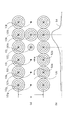
- FIG. 3 is a diagram for explaining the principle of the method according to the present invention.
- FIG. 3 shows an image of an electric field generated when an electric pulse is applied to the electrode means 10a to 10f arranged in a line at a predetermined interval d.
- six electrode means 10a to 10f are shown.
- the number of electrode means 10 is not limited to six.
- ginger regions 12a to guiding paths 12c are formed.
- a large number of electrode means 10 are arranged side by side.
- an electric pulse is applied to the electrode means 10a, 10c, 10e (becomes a positive pole), and the adjacent electrode means 10b, 10d, 10f are set to 0 [V] ( ⁇ Pole).
- an electric pulse is applied to the electrode means 10b, 10d, and 10f, and the electrode means 10a, 10c, and 10e become 0 [V].
- the negative pole does not necessarily have a polarity different from 0 [V] or the positive pole side, and may be a potential that causes some potential difference between the positive pole side and the negative pole.
- FIG. 3 schematically shows the intensity of the electric field generated in each period around the electrode means 10a to 10f in the case of such a case in the form of an equipotential line 30.
- the equipotential lines 30 around the respective electrode means 10a to 10f represent only a partial range, but in practice, the electric field is of course also in a range farther than this. It may extend, or may extend to the next electrode means or to a range farther than that.
- the equipotential lines 30 are shown concentrically so as to surround the respective electrode means 10a to 10f. Therefore, the region where the electrode means 10a to 10f arranged in a row at a distance from each other is connected is covered by the concentric equipotential lines 30.
- An electric field generated by an electric pulse applied to each of the electrode means 10a to 10f is generated in a region covered by the equipotential lines 30, that is, an entire region where the electrode means 10a to 10f are arranged in a line.
- fish 32 approaches or enters the area, it receives electrical stimulation.
- the electric pulses applied to the electrode means 10a to 10f are set so as to generate an electric field that gives an electrical stimulus that the fish 32 dislikes.
- the fish 32 tends to move toward a direction where the electrical stimulation becomes weaker and a direction where the electrical stimulus is lost. Accordingly, the fish is guided away from the electrode means 10a to 10f, that is, toward the arrow 34a in FIG. Conversely, the closer to the electrode means 10a to 10f, the stronger the electric field and the stronger the electrical stimulation, so that the fish does not move in the direction approaching the electrode means 10a to 10f, that is, in the direction of the arrow 34b in FIG. In this way, an electric field barrier is formed and the fish cannot pass between the electrode means 10a to 10f.
- an electric field is generated around the electrode means to which the electric pulse is applied, and this electric field changes depending on the distance from the electrode means.
- the closer to the electrode means the stronger the electric field and therefore the greater the stimulation the fish receives.
- susceptibility to fish stimulation also depends on other parameters such as frequency.
- the strength of the electric field will be mainly described, but the “intensity” of the stimulus received by the fish by the electric field is intended rather than the physical “intensity” of the electric field itself. Note that there may be cases.
- the degree of irritation felt by the fish due to the electric field generated by the electric pulse / the influence of the fish depends on the type, size and / or various organs of the fish, Varies depending on fins, floats, etc.
- Various parameters, such as average voltage or average current, peak value, duty ratio, frequency, etc. of the electrical pulse, depending on the specific personality, such as the type of fish, the size and / or the sensitivity of the various organs that are intended to act By adjusting, it is possible to appropriately control the degree and type of stimulation received by the fish.
- a plurality of electrode means 10 are arranged at intervals from each other along a substantially rectangular outline forming the ginger region 12 a, and the electrode means adjacent to these electrode means 10
- an electric pulse as shown in FIG. 2 is applied between 10
- an electric field for applying electrical stimulation as shown in FIG. 3 is generated in water.
- a barrier is formed by an electric field that prevents fish from passing along the outline of the ginger region 12a, and the fish can be guided to be confined in the ginger region 12a.
- any one or a plurality of electrode means for example, electrode means 10c and 10d, among the electrode means 10a to 10f shown in FIG. 3, are assigned to the entrance / exit 12b in FIG.
- the entrance / exit can be opened / closed by switching on / off electrical pulses to the electrode means 10c, 10d assigned to the entrance / exit 12b.
- an electric pulse is applied to the electrode means 10c and 10d assigned to the entrance 12b.
- an electric field is also formed at the positions of the electrode means 10c and 10d, and an electric stimulus is given to the fish that tries to pass through the electric field, and the fish in the ginger region 12a
- the fish that are guided to be trapped in and outside the ginger region 12a are locked out of the ginger region 12a.
- the entrance / exit 12b is simply opened so that the fish in the ginger region 12a naturally notices the entrance / exit 12b and moves to the guide path 12c.
- an electric pulse that gives a stronger stimulus is applied in order from the electrode means 10 that is far from the entrance / exit 12b, and the fish leaves the area and enters the entrance / exit 12b.
- fish attracting means for attracting fish may be provided in the vicinity of the entrance 12b or in the guide path 12c.
- the fish attracting means may be a light attracting light (such as a light bulb, an LED, or a light emitting element such as a laser) that emits light that is preferred by the fish, or an electricity that the fish prefers.
- It may be an electrode means for generating a stimulus.
- This fish attracting means may be attached to the electrode device 10, or may be provided integrally, or may be provided separately from the electrode device 10.
- a driving-in means may be provided.
- a jet water flow may be generated using a pump or the like, and the fish may be moved in the water flow.
- FIG. 4 is a diagram illustrating an embodiment of an arrangement of electrode means 10 that forms, for example, a guide path 12c.
- an image of an electric field generated when an electric pulse is applied to the electrode means 10g to 10l.
- the electrode means 10 g to 10 l arranged in a row at intervals are arranged in two rows with a substantially constant width w.
- the same intensity electric pulse is applied to the electrode means 10g to 10k as in the electrode means 10a to 10f shown in FIG. Therefore, as described above, an electric field is formed so that fish cannot pass through the rows formed by the electrode means 10g to 10k.
- the guide path 12c is formed.
- the fish moves in the guide path 12c mainly in the left-right direction in the figure. That is, the fish cannot go out from the guide path 12c nor enter the guide path 12c across the row of the electrode means 10g to 10l.
- an electric pulse stronger than the electrode means 10g to 10k is applied to the rightmost electrode means 10l of the two rows of electrode means 10g to 10l, and a strong electric field is formed around the electrode means 10l.
- the intensity of this strong electric pulse applied to the electrode means 10l is such that the stimulation by the electric field formed around the electrode means 10l is caused by the fish at any position across the width W direction between the at least two electrode means 10l, 10l. Is set to produce sufficient stimulation to prevent the passage of the. (Hereinafter, such (relatively strong) electric field and electric pulse may be simply referred to as “strong electric field” and “strong electric pulse”.) Therefore, between the rows of electrode means 10g to 10l.
- a barrier due to an electric field is generated at a position sandwiched between the electrode means 10l in the formed guiding path 12c, and the fish is sandwiched between the electrode means 10l and 10l to which the above-described strong electric pulse is applied in the guiding path 12c. Cannot pass through the designated area. Accordingly, the fish cannot move in the direction of the arrow 42b in the guide path 12c, and is thus guided in the direction of the arrow 42a.
- the electric pulse intensity is increased to form an electric field that can be stimulated over a wider range (that is, the entire direction across the induction path).
- Other parameters can also be adjusted to create the applied electric field. That is, by changing the frequency, pulse width, duty ratio, and other various parameters, for example, by selecting a value that is more sensitive to the target fish, or by selecting a value that is easy to propagate to a wider range
- an electric field that gives stimulation over a wider range can be formed.
- This strong electric pulse is applied to the electrode means 10l and 10l for a predetermined period, and then applied to the adjacent electrode means 10k and 10k. At this time, the electric pulse applied to the electrode means 10l and 10l may maintain the same intensity as the above-mentioned strong electric pulse, or can be weakened to the same intensity as the other electrode means 10g to 10j. Subsequently, after a predetermined period has passed, an electric pulse having the same intensity as the above-described strong electric pulse is applied to the adjacent electrode means 10j. In this way, a strong electric pulse is sequentially applied to the adjacent electrode means along the desired moving direction according to the speed at which the fish moves, and a barrier due to the electric field formed by this strong electric pulse is formed.
- the fish is gradually moved toward the direction of guiding the fish in the guide path 12c.
- the fish in the guide path 12c is moved and guided in the direction of the arrow 42a in the figure as if it is gradually pushed from behind to the barrier by the electric field formed by this strong electric pulse. To go.
- fish attracting means for attracting fish may be provided.
- various types of means can be used alone or in combination as the fish attracting means.
- the above-described driving means may be provided.
- FIG. 5 shows another example of the arrangement of the electrode means 10 in the guide path 12c.
- FIG. 5A is a diagram showing the arrangement of the electrode means 10 in the guiding path 12c.
- FIG. 5B shows the intensity of the electric field generated near the center in the width direction of the guiding path 12c in FIG. FIG.
- two rows of electrode means 10g to 10l are provided substantially parallel to each other, and a guide path 12c is formed therebetween. Further, one row of electrode means 10'g to 10'l is provided between the two rows of electrode means 10g to 10l.
- an electric pulse is applied to one electrode means 10'k of the electrode means 10'g to 10'l in the central row, and an electric field is generated around it. Due to the electric field formed by the electrode means 10k, 10k and the central electrode means 10′k that form the outline of the guide path 12c, the position of the electrode means 10′k in the guide path 12c reaches the entire width of the guide path 12c.
- FIG. 5B shows a change in electric field strength near the center in the width direction in the guide path 12c.
- the horizontal axis in FIG. 5B corresponds to the horizontal direction in FIG. 5A, and the vertical axis corresponds to the electric field strength.
- Curve 54 shows the strength of the electric field at each location.
- the electrode means 10'g to 10'l in the center row are applied with the electrical pulses as described above to the electrode means 10'k, and in addition to the electrode means 10'k, especially for guiding fish.
- An electric pulse weaker than that of the electrode means 10′k may be applied to the electrode means 10′j adjacent to the direction in which it is intended. This electric pulse creates a weak electric field around the electrode means 10'j. Therefore, as shown by the curve 54, the electric field in the vicinity of the center in the width direction of the guide path 12c shows a low value (for example, it may be 0) from the electrode means 10′g to 10′j.
- the electrode means 10′i As the electrode means 10′i approaches the electrode means 10′j, it gradually begins to rise, becomes the highest at the position of the electrode means 10′k, and begins to fall as it moves away from the electrode means 10′k. Then, when the fish on the left side of the electrode means 10′k in the guide path 12c in FIG. 5, for example, the fish in the vicinity of the electrode means 10′i moves to the right side in the figure, the electric field gradually increases. The strength of the electrical stimulation received also becomes stronger. Therefore, the fish itself moves in the direction in which the stimulation by the electric field is weakened, that is, in the direction of the arrow 52a. Therefore, before approaching the electrode means 10'k, the fish in the guide path 12c starts to move in a direction where electric stimulation due to an electric field is weaker when approaching the electrode means 10'j.
- the next electrode means more specifically, the next in the direction in which the fish is to be guided.
- An electrical pulse similar to the electrical pulse applied to the electrode means 10′k is applied to the electrode means, for example, the electrode means 10′j.
- the weak electric pulse applied to the electrode means 10'j is further applied to the electrode means 10'j adjacent thereto.
- the electric pulse and the weak electric pulse are sequentially applied to the adjacent electrode means in the desired direction, thereby depending on the electric field formed by these electric pulses.
- the barrier is gradually moved toward the direction in which the fish is to be guided in the guide path 12c to guide the fish.
- the electrode means 10 When an electric pulse is applied to the electrode means 10 in water, for example, when applied in seawater, the electrode means 10 may cause elution of the material of the electrode means due to the effect of ion conduction, corrosion due to oxidation, Damage may be unavoidable due to accumulation of kimono.
- the intensity of the electric pulse is increased, that is, when the voltage value / current value of the applied electric pulse is increased, such damage may be increased.
- the degree of damage caused to each electrode means 10 can be kept low.
- FIG. 6 shows still another example of the arrangement of the electrode means 10 in the guide path 12c.
- two rows of electrode means 10m to 10s are arranged in a zigzag shape. That is, in the guiding path 12c, the electrode means 10m, 10o, 10q, 10s arranged on the inner side and the electrode means 10n, 10p, 10r arranged on the outer side are alternately arranged to form two rows. is doing.
- an electric pulse having the same intensity is applied to the electrode means 10m to 10r among these electrode means 10m to 10s, and the rightmost electrode means 10s in FIG. A strong electrical pulse is applied. Thereafter, this strong electric pulse is sequentially applied to the adjacent electrode means at predetermined time intervals.
- the electrode means 10m to 10s are arranged in a zigzag shape, for example, as shown in FIG. 7 (in FIG. 7, the reference to the lower electrode means in the figure is omitted, The electrode means are considered to have the same reference numerals as in FIG. 6.)
- One electrode means 10o second electrode means from the left in the lower row in the figure
- the distance in the longitudinal direction of the guide path 12c is shorter than the distance between the adjacent electrode means. That is, for example, when one electrode means 10o is missing in the form shown in FIG. 6, the distance between the remaining adjacent electrode means 10n and 10p is 1 in the form illustrated in FIGS. When one electrode means is missing, it becomes shorter than the distance between the adjacent electrode means remaining. Therefore, the remaining electrode means 10n, 10p can cover the electric field of the portion lacking due to a failure or the like and form the electric field so as to cover the outline of the guiding path 12c.
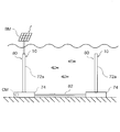
- FIG. 8 is a view showing an embodiment of an electrode device 70 including electrode means used in the present invention.
- FIG. 8A shows a process of installing the electrode device 70 at a predetermined position in water.
- FIG. 8B shows the electrode device 70 in which the electrode means 10 to which an electric pulse is applied and the electrode means. This represents a state in which the fixing means 74 for fixing at a desired installation position in water is connected. When an electric pulse is applied, an electric field is formed in the water.
- the electrode means 10 includes a linear portion 72a having a conductive and corrosion-resistant surface that extends at least partially from the water bottom toward the water surface, and the fixing means 74 is provided at the lower end of the linear portion 72a. At the upper end of the linear portion 72 a, a float 76 that supports the linear portion 72 a with the fixing means 74 is provided.
- FIG. 8A schematically shows the inside of the float 76.
- the float 76 is a substantially spherical shell having a space inside, and is configured to float on the water surface.
- the linear portion 72a is stored inside the float 76 in a wound state, and when the float 76 reaches the fixing means 74, The linear part 72a is unwound.
- a propulsion unit such as a propeller or a jet water flow generator and a position detection unit such as a GPS device
- a position of the float is detected while detecting the position via the position detection unit.
- the linear member 72a can be unwound by automatically proceeding to the position via the propulsion means and reaching the target position.
- a mutual position detecting means capable of detecting the mutual positional relationship between the fixing means 74 and the float 76 may be provided.
- a transmitter may be provided on the fixing means 74 side
- a receiver for receiving a signal from the transmitter may be provided on the floating side
- a radar or the like may be provided on the floating side. It may be done.
- connection part 78 which connects the linear part 72a and the fixing means 74 so that attachment or detachment is possible is provided in the lower end of the linear part 72a of the electrode apparatus 70. As shown in FIG.
- the connecting portion 78 provided at the lower end of the linear portion 72a approaches the fixing means 74 disposed on the bottom of the water.
- the connecting portion 78 reaches the depth of the fixing means 74 provided at the bottom of the water, it is connected to the fixing means 74 and the electrode means 10 is fixed at a predetermined position.
- the upper surface of the fixing means 74 and the lower surface of the connecting portion 78 may be provided with screwing portions that are screwed together, or magnets that are attracted to each other may be provided.
- the connecting portion 78 can be detachably attached to the fixing means 74 by turning on and off the current flowing through the coil.
- the electrode means and the fixing means are configured to be detachable, the electrode means and the fixing means can be detached from the fixing means during maintenance. Even if the electrode means is corroded or the deposits deposited on the electrode means reach a certain level (amount) and the desired electric field cannot be obtained, the electrode means is fixed. The electrode means can be pulled out of the water for maintenance. Also, another new electrode means can be immediately connected to the fixing means from which the electrode means has been removed, and the electrode device can be used again. Further, according to such a configuration, for example, when replacing the electrode means used in water, the electrode means is removed while leaving the fixing means in place, and a new electrode means is attached to the remaining fixing means. By attaching, the electrode means can be easily installed at the original position.
- the electrode means is configured so that an electric field can be formed in water due to its function, it may be affected by electric corrosion, etc., and therefore requires more frequent maintenance than the fixing means. In some cases, the lifespan must be relatively short. Then, if replacement / maintenance is performed while the electrode means and the fixing means are connected, the fixing means is pulled out of the water in a short cycle that is not necessary for the fixing means, and in some cases, the electrode means and the electrode means are replaced. The efficiency is reduced. If the electrode means and the fixing means are configured to be detachable, the electrode means can be lifted out of the water as needed while leaving the fixing means in the water, so that maintenance and / or replacement can be performed. And cost efficiency.
- the fixing means is configured to be able to fix the electrode means in water against the buoyancy applied to the fixing means itself and the electrode means, it takes a great deal of labor to pull it up. .
- the electrode means can be pulled up relatively easily, if the electrode means can be pulled up separately from the fixing means, the labor for lifting itself can be reduced.
- the linear portion 72 a is supported in a state of being installed between the float 76 and the fixing means 74.
- the linear portion 72a is supported in a tensioned state between the float 76 and the fixing means 74 by the buoyancy applied to the float 76.
- the linear portion can be linearly held by the tension applied to the linear portion between the fixing means and the float. Since the linear portion serving as the electrode means is held in a straight line, when a plurality of electrode means are arranged side by side, the distance between the adjacent electrode means is kept within a certain range, and therefore the electrode means It is possible to form an electric field having a constant strength over the longitudinal direction.
- a flexible braided wire pipe or a wire can be applied to the linear portion 72a.
- a braided wire made of stainless steel can be used as the braided wire pipe or wire.
- a wire made of other conductive materials such as platinum, iridium, ruthenium, rhodium, titanium, copper, chromium, carbon, and / or an alloy containing them is knitted. You may also use a stuffed one.
- a conductive polymer material made of polyacetylene, polypyrrole, polythiophene, polyaniline, or the like, or a composite material in which an inorganic and / or organic (for example, carbon) conductive material is added to the polymer material can be applied.
- the braided wire pipe or wire may be subjected to a corrosion-resistant coating or plating. In the corrosion-resistant coating, the braided wire or pipe may be coated as a whole, or the strand may be coated.
- the linear portion When the surface of the linear portion has conductivity, the linear portion itself can function as an electrode, and an electric field can be generated in water by an electric pulse applied to the electrode means. Further, when the linear portion has a corrosion-resistant surface, it is possible to reduce deterioration of the electrode means due to being installed in water and being applied with electricity. Further, when the electrode means is formed in a linear shape, the structure of the electrode means can be simplified, the shape is simplified and the maintainability is improved as compared with the conventional net-like structure. In addition, when the linear portion includes a flexible pipe or wire, the pipe or wire has a relatively thin shape, so that the linear portion is less likely to receive the force of water flow in water. Moreover, when the linear part has flexibility, the force of the water flow can be suitably received.
- the wire can be handled in a wound state, and the electrode means can be handled easily.
- the linear portion is a braided wire pipe or wire, water can pass between the braided wires, so that the force of the water flow can be released as appropriate, and the material, thickness,
- the linear portion may be, for example, a linear solid conductor rod, a hollow conductor pipe, or a flexible conductor wire that is supported by being pulled in a straight line. Good. Further, it is sufficient that at least a part of the surface of the linear portion is conductive and corrosion-resistant, and the inside and other portions of the surface may be nonconductors such as plastic, concrete, and earth and sand.
- the fixing means 74 may have a weight capable of fixing the electrode means 10 in water, or may have a fixing portion 74a fixed to the water bottom. If the fixing portion 74a is provided, the fixing means 10 can be more firmly fixed to the water bottom. Therefore, even when a large force is applied to the electrode means, such as when the water flow is intense, the electrode means does not shift. On the other hand, if the fixing means 74 has a weight capable of fixing the electrode means 10 in the water, the fixing means 10 can be further submerged in the water without requiring work for fixing the fixing means 74 to the bottom of the water. The fixing means 10 can be easily installed on the bottom of the water, and the electrode means can be easily installed at a desired position in water.
- the electrode device 70 may be provided with a battery module BM.
- FIG. 8B shows an example in which a solar cell module is attached to the upper hemisphere of the float 76 as the battery module BM.
- various battery power generation modules such as a seawater battery module, a wind power generation module, and a tidal power generation module can be applied to the battery module BM.
- the battery module may include a storage battery in addition to these power generation modules. For example, if the battery module includes a solar battery cell and a storage battery, the electric power generated in the daytime using the solar battery cell is stored in the storage battery, and the power necessary for the electrode device is constantly passed through the battery module. Can be covered.
- the battery module includes a tidal power generator, a wind power generator, or a plurality of different types of power generation means, power can be stably supplied without a storage battery. it can.
- These power generation modules BM may be provided in each electrode device 70, for example, one battery module BM may be provided for one pair or several electrode devices 70. If the power generation module BM can stably supply all the power used by the electrode means 10, the electrode device 70 including the power generation module BM need not be provided with a power supply cable. Therefore, the trouble of laying a cable for connecting the plurality of electrode means 10 to each other and the power source can be saved. In particular, when a large number of electrode devices are arranged in a wide area such as the sea, it is very useful to save the trouble of laying the cable. Further, if one power generation module BM is provided for one pair or several electrode devices 70, only a few electrode means 70 corresponding to one power generation module BM need to be connected by wire. .
- the number of battery modules can be saved rather than connecting the battery modules one by one to all the electrode devices constituting the aquaculture system, and it is necessary to lay the electric wires over a wide range so as to cover all the electrode devices. Since there is no, it is easy to lay the electric wire.
- the power generation module BM can be used as a backup power source in case of an emergency or failure of the power supply facility after providing a cable for supplying power to each electrode device 70.
- the electrode device 70 may be provided with a communication module CM that communicates with a control unit that controls an electric pulse.
- FIG. 8B shows an example in which a wireless communication module CM is provided inside the float 76.
- the electrode device 70 can receive a signal for determining an electric pulse to be applied to the electrode means 10 from the control means.
- position information of the electrode device 70 information indicating the state of damage or corrosion of the electrode means 10, information regarding the state of connection with the fixing means 74, and the like can be transmitted to the control means.
- the position information of the electrode device 70 can be acquired by GPS or the like, or can be relatively more precisely obtained based on the positional relationship with the peripheral electrode device 70.
- the communication module CM is wireless, it is possible to save labor for laying an electric wire for communication of a control signal between the control unit and the electrode device.
- the position of the moving body that moves in and near the area where the plurality of electrode means 10 are provided can be determined precisely based on the mutual positional relationship with each electrode means 10.
- FIG. 9 is a diagram showing another embodiment of the electrode device.
- FIG. 9 exemplarily shows two electrode devices 80. These electrode devices 80 are directly provided with a linear portion 72a as the electrode means 10 on the upper surface of the fixing means 74 provided on the bottom of the water.
- the linear portion 72a is formed of a braided wire pipe as described above.
- One electrode device 80 is provided with a battery module BM, and is connected to the other electrode device 80 via a cable 82. In this way, electricity generated by one battery module can be supplied to a plurality of electrode devices. In addition, various signals can be exchanged between the electrode devices 80 via the cable 82.
- FIG. 8 a further embodiment of the electrode device 70 is shown in FIG.
- the electrode device 70 of the present embodiment is different from the first embodiment shown in FIG. 8 in that the electrode means 110 formed in a linear shape in the first embodiment shown in FIG. It is different from the embodiment.
- substantially the entire linear portion 72a is formed to be conductive, but in this embodiment, the linear portion 172 is formed to be non-conductive and has a plurality of points.
- the electrode 174 is provided to be attached to the linear portion 172 so as to be separated from each other. In the present embodiment, these point electrodes 174 are provided on the linear portion 172 at equal intervals.
- the point-like electrodes 174 are distributed at equal intervals in the water depth direction.
- the interval between the dotted electrodes is not necessarily equal, and the dotted electrodes 174 may be arranged so that the distance between the bottoms of the water is smaller and gradually increases toward the water surface, Conversely, the point-like electrodes 174 may be arranged so that the interval is larger at the bottom of the water and gradually decreases toward the water surface.
- Wirings are respectively attached to the linear portions 172 so that electric pulses can be individually applied to the respective point-like electrodes 174. In response to a command from the control unit 20, an electric pulse is selectively applied to each point electrode.
- a strong electric pulse is applied to the point-like electrodes 174 arranged on the bottom side, as schematically shown in FIG.
- the fish can be guided to the water surface direction 134a, that is, a position where the water depth is shallow.
- a strong electrical pulse is applied to the dotted electrode 174 disposed on the water surface side and a weak electrical pulse is applied to the dotted electrode disposed on the water bottom side, the fish is moved in the bottom direction 134b, that is, in the depth of water. It can be guided to a deep position.
- an electric pulse having the same strength is applied to each of the dotted electrodes 174 provided on one linear portion 172, a uniform electric field can be formed in the water depth direction.
- the fish when fish can be guided not only in the water surface direction (ie, horizontal direction) but also in the water depth direction (ie, vertical direction), for example, when trying to catch cultured fish, the fish is guided in the water surface direction. Can do. For example, when the flow near the water surface is rough, the cultured fish can be guided toward the bottom of the water. In addition, when the water quality is distributed in the depth direction for some reason, the fish can be guided to a more preferable depth region of the water quality.
- the intensity, frequency, duty ratio, etc. of the electric pulse according to the type and size of the fish, it is possible to select the fish not only in the water surface direction but also in the water depth direction. It becomes possible to guide to a desired position every time. For example, by arranging the sacrificial region according to the type of fish partially overlapping in the water depth direction, guiding the necessary type of fish to the shallower or deeper direction according to the season, feeding, and catching time. Can do.
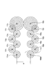
- FIG. 12 is a diagram schematically showing another embodiment of the electrode device.
- the linear portion 274 is installed to be inclined with respect to the vertical direction in water. More specifically, two floats 76 are arranged on the water surface, and fixing means 74 for fixing them in the horizontal direction is arranged directly below each float 76. Another fixing means 74 is provided between the fixing means 74, and the linear portion 274 is bridged from each float 76 to the other fixing means 74.
- the line-shaped portions 274 are provided with point-like electrodes 174 at equal intervals. As a result, the point-like electrodes 174 are arranged obliquely with respect to the vertical direction and radially arranged from the bottom to the water surface when viewed from the water surface.
- the dotted electrodes 174 are arranged in this way, first, even if an electric pulse of the same strength is applied to each of the dotted electrodes 174, the water-side dotted electrodes 174 are close to each other. In comparison with, the strength of the electric field is relatively strong. Therefore, the fish is guided toward the water surface. After that, as shown in FIG. 13, when a strong electric pulse is applied to the dotted electrode 174 on the bottom of the water, the fish is further guided toward the water surface.
- the point-like electrodes 174 are arranged in a three-dimensional matrix in water, as shown in FIG.
- An electric field distribution similar to that of the fourth embodiment can be obtained by applying an electric pulse to the point-like electrode 174 at a position corresponding to the fourth embodiment.
- the distance between the linear electrodes 174 can be narrowed near the water surface and widened near the bottom of the water.
- another float 76 is provided between the floats 76, and between this another float 76 and the fixing means 74 at both ends.
- the linear part 274 can be bridged and arranged.
- the electrode means 10 is first arranged so as to form the ginger region 12a and the guide path 12c communicating with the ginger region 12a through the entrance 12b. Then, an electric pulse is applied to the electrode means 10.
- An electric pulse is controlled and applied to the electrode means 10 by the control means as follows. That is, the electric pulse is set and applied so that an electric field is generated so that the fish is guided in the guide path 12c toward the ginger region 12a.
- the control means does not apply an electrical pulse to the electrode means 10 of the entrance 12b, and the entrance 12b is opened.
- the control means applies an electric pulse to the electrode means 10 of the entrance 12b to close the entrance 12b.
- Whether the fish in the taxiway 12c has entered the ginger region 12a is detected by detecting the number of fish remaining in the taxiway 12c, the number of fish having passed through the entrance 12b, and / or the number of fish having entered the ginger region 12a, A determination can be made based on this.
- a known fish finder, an optical detector, or the like may be used.
- An electric field is formed through the electrode means of the present invention, and the current flowing therethrough , And by analyzing the current value together with the position information of the electrode means, it may be determined how much fish is in which position in the electric field.
- the fish When the fish enters the ginger region 12a, the fish is raised and grown in the ginger region 12a for a predetermined period. In the meantime, for example, food of cultured fish bred in the ginger region 12a, such as small fish, can be sent from the port side to the ginger region 12a side via the guide path 12c.
- an electric pulse is applied to the electrodes to generate an electric field so that the ginger region 12a is further divided into two or more sections.
- the electrodes can be guided to any section.
- the fish may be guided to a desired section in combination with the above-described fish collecting means and / or driving-in means.
- the cultured fish When the cultured fish has grown to a state suitable for shipping, the cultured fish can be guided from the ginger region 12a to the vicinity of the port via the guide path 12c.
- a ginger region 12a can be formed in the aquarium, an electric field can be generated in the ginger region 12a and divided into a plurality of sections, and a desired fish can be classified into a desired section according to the size of the fish.
- it can also be used when guiding and dispersing using an electric field or isolating a specific fish so that the fish does not concentrate too much at a specific location in the aquarium.
- the method or system according to the embodiment of the present invention is used to guide the fish there, and the (substantial) If a (substantial) taxiway is connected to the doorway, the inside of the taxiway can be guided using this method or system.
- the aquaculture system 1 may be provided with various sensors for detecting the water temperature, the air temperature, the speed of the water flow, the density of the food, the growth status of the cultured fish, and the like.
- the control means can determine what electric pulse is applied to which electrode means 10 based on the detection values from these sensors.
- the control means may be programmed in advance so as to apply a predetermined electric pulse to the predetermined electrode means 10 at a predetermined date and time. At that time, for example, individual threshold values are set for the detection values by the above-mentioned various sensors, or complex conditions are set, and what electric pulse is applied to which electrode means 10 is a pre-patterned table. And an electric pulse may be applied to each electrode means according to the table.
- a plurality of these threshold values and tables are stored according to the type of the cultured fish, and can be read and used as appropriate according to the type of the current cultured fish.
- fish has been described as an example of an aquatic organism.
- the scope of the present invention is not necessarily limited to biological fish, but mammals such as whales, dolphins, fur seals, sea lions, and the like. It can be applied to reptiles such as crocodiles, amphibians such as frogs, jellyfish, squid, octopus, shrimp, and algae.
- reptiles such as crocodiles, amphibians such as frogs, jellyfish, squid, octopus, shrimp, and algae.
- shellfish and cormorants as a protective fence to keep away living organisms that prey on these and organisms that are harmful to them It is also possible to apply the present invention.
- the electrode means or the electrode device may have a light emitter such as a light, such as a so-called lamp buoy, on the upper part thereof. If such a light emitter can change color, brightness, etc., the state of the electric pulse applied to each electrode means can be visually recognized from the outside by the display mode / light emission mode of the light emitter. Then, the use state of the above-mentioned ginger region, doorway and / or taxiway, for example, in which range the ginger region is used, whether the doorway is closed, or in which direction the fish is guided It can be confirmed at a glance on the spot.
- a light emitter such as a light, such as a so-called lamp buoy
- each electrode means or electrode device has a self-diagnosis function, and the display mode / light emission mode of the illuminant is determined according to its own state, for example, the degree of deterioration of the electrode means, the presence or absence of a failure, the type of failure, May be different.
- the display mode / light emission mode of the illuminant is determined according to its own state, for example, the degree of deterioration of the electrode means, the presence or absence of a failure, the type of failure, May be different.
- the electrode means / electrode device are arranged in a matrix, the light emission mode of the light emitter is changed regardless of the state of the electrode means, and the outside, particularly the upper part, for example, You may display some message with respect to the person of the sky, for example, advertisement.
- the float is configured to be visible from the surface of the water, it can be used as a mark for recognizing that the electrode device is installed on the ship that navigates the surface of the water. , Can ensure both the safety of far
- FIG. 14 is a diagram illustrating the procedure of the method according to the embodiment of the invention. Hereinafter, each step shown in FIG. 14 will be described.
- Step S101 A fish (eg, fry) before being raised in a predetermined area (eg, ginger area) is moved from the first place to the predetermined area and moved.
- a predetermined area eg, ginger area
- Such movement includes, for example, swimming and moving fish (eg, fry) before breeding in the predetermined area (eg, ginger area) in the water surface direction and / or the water depth direction. This is achieved, for example, by applying a first external factor in the water surface direction and / or water depth direction to the fish before being raised in the predetermined region.
- Examples of the first external factor include, for example, an electric field, a magnetic field, a water flow having a water pressure larger than the thrust of the fish before being raised in the predetermined region, an anoxic water mass, ultrasonic waves, light, air ( Bubbles), changes in water temperature, or natural enemies of fish before breeding in the predetermined area or imitating the natural enemies (for example, pseudo food), but is not limited thereto.
- Step S102 From the second place to the predetermined area, the fish serving as the food for the fish being bred in the predetermined area is swam and moved.
- Such movement includes, for example, swimming and moving a fish serving as a food for the fish being bred in the predetermined area in the water surface direction and / or the water depth direction. This is achieved, for example, by applying a second external factor in the water surface direction and / or the water depth direction to the fish serving as the food.
- the second external factor for example, an electric field, a magnetic field, a water flow having a water pressure larger than the thrust of the fish serving as a bait, an anoxic water mass, an ultrasonic wave, Although it is light, air (bubble), a change in water temperature, or a natural enemy of fish serving as its food, or imitating the natural enemy (for example, pseudo food), it is not limited to these.
- Step S103 The fish (for example, adult fish) reared in the predetermined area is moved from the predetermined area to the third place by swimming.
- Such movement includes, for example, swimming and moving a fish (for example, an adult fish) after being raised in the predetermined area in the water surface direction and / or the water depth direction. This is achieved, for example, by applying a third external factor in the water surface direction and / or the water depth direction to the fish after being reared in the predetermined region.
- the third external factor similarly to the first external factor and the second external factor, for example, an electric field, a magnetic field, larger than the thrust of the fish itself after being raised in the predetermined region
- region is not limited to the fish which grew to an adult fish.
- the fish after being raised in the predetermined region may be a fish that is growing up to an adult fish.
- the fish after being reared in the predetermined area is captured at the third place.
- Such capture is done by human power or using a machine.
- this capture may be performed in water near the water surface, may be performed near the bottom of the water, may be performed at a depth intermediate between the water surface and the bottom of the water, or air near the water surface. It may be done in.
- region is not ask
- the third external factor may be used for subsequent capture, or may be captured using a net.
- the capture moves the fish after being raised in the predetermined area to swim to a third location in the water, which is then substantially in latitude and longitude from the third location in the water. It is also possible to perform the swimming at the fourth place near the water surface after swimming and moving the fish after being raised in the predetermined area to the fourth place near the water surface that is equal to and different in water depth only. That is, immediately after the capture, the fish after being reared in the predetermined area may be moved and moved only in the depth direction from the third place in the water to the fourth place near the water surface.
- This is suitable, for example, for aquaculture of fish that prefer low temperatures (eg, salmon). This is because a fish that prefers a low temperature is required to capture and land the fish before the water temperature rises because the quality of the fish itself decreases when the water temperature rises.
- the water depth level when moving the fish after being raised in the predetermined area from the predetermined area to the third place is moved from the first place to the depth of the fish before being raised in the predetermined area.
- This is suitable, for example, for flounder culture. This is because flounder larvae have the property of swimming at a depth level close to the water surface, whereas adult flounder fishes have the property of swimming at a depth level close to the bottom of the water.
- first place, the second place, and the third place may be the same place.
- first place and the second place may be ports (for example, the port 16 shown in FIG. 1 to be described later), or the first place, the second place, and the third place may be , All may be ports (for example, the port 16 shown in FIG. 1 described later).
- the route through which the fish before being raised in the predetermined area swims and moves, and the fish serving as food swims and moves may be exactly the same, or at least some of these paths may overlap or may be completely different.
- the fish before being raised in the predetermined area and the fish serving as the food may be moved from the first place (or the second place) to the predetermined area by simultaneously swimming.
- the route through which the fish before being raised in the predetermined area swims and moves and is raised in the predetermined area.
- the path through which the subsequent fish swims and moves may be exactly the same, or at least a part of these paths may overlap or may be completely different.
- the route through which the fish serving as the food swims and moves, and the fish after being raised in the predetermined area swim.
- the paths that pass when moving may be exactly the same, or at least some of these paths may overlap or may be completely different.
- the first external factor, the second external factor, and the third external factor may all be the same, or at least one of them may be different.
- the first external factor is given to the fish by the first external factor giving means.
- the second external factor is given to the fish by the second external factor giving means.
- the third external factor is given to the fish by the third external factor giving means.
- the first external factor assigning means, the second external factor assigning means, and the third external factor assigning means may be configured by a single means, or at least one of them may be It may be configured by separate means.
- the first external factor applying unit, the second external factor applying unit, and the third external factor applying unit are configured by a single unit called the control unit 20 shown in FIG. Is possible.
- the influence on the fish before being raised in the predetermined area due to the application of the first external factor becomes smaller in the direction in which the fish before being raised in the predetermined area is going to be moved. You may do it. Thereby, it is possible to guide the fish in a direction in which the influence given by the first external factor becomes smaller. In this way, it is possible to smoothly swim and move the fish in the direction that the user intends to move the fish. In addition, if you want to change the direction you want to move the fish because of a sudden change in the weather during the movement of the fish, you can change the direction of the fish by increasing the influence of the direction of the fish's movement. Is possible.
- the external factor is at least one of an electric field generated by applying a voltage to the plurality of electrode means and a magnetic field generated by a current flowing through the plurality of electrode means, and 4, when a plurality of electrode means 10g to 10l arranged in a row at a distance from each other are arranged in parallel in two rows, after the voltage applied to the electrode means 10g is increased,
- the direction in which the fish is desired to move can be changed from the direction of the arrow 42a to the direction of the arrow 42b by reducing the voltage applied to the electrode means 10l to the same level as the electrode means 10i.
- the impact on the prey fish due to the application of the second external factor and the impact on the fish after being raised in that area by the application of the third external factor are also: You may make it become small toward the direction which is moving those fish. Thereby, it is possible to guide the fish in a direction in which the influence given by the second external factor and the third external factor becomes smaller. In this way, it is possible to smoothly swim and move the fish in the direction that the user intends to move.
- the magnitude of the influence caused by the third external factor being applied to the fish after being reared in the predetermined area By reducing the size from the bottom to the water surface, the fish after being reared in the predetermined area may be moved from the bottom to the water surface while being moved.
- the user can capture the fish after being raised in the predetermined area in the water as compared with a normal capture operation.
- the magnitude of the influence caused by the external factor applied is reduced as it moves from the water surface to the bottom of the water, so that the fish moves while swimming from the water surface toward the bottom of the water. You may make it make it. Thereby, for example, when a harmful substance or an obstacle floats on the water surface, it can be moved while avoiding the water surface.
- the method for culturing fish includes all of steps S101 to S103 has been described as an example, but the present invention is not limited to this.
- the method for culturing fish of the present invention should be recognized as a method including at least one of steps S101 to S103. That is, a method including any one of steps S101 to S103, a method including any two steps of steps S101 to S103, or all steps of steps S101 to S103 are included. All methods are within the scope of the method of culturing fish of the present invention.
- step S101 when it is not necessary to put fish (for example, fry) before being raised in the predetermined area into the predetermined area because a fish egg has hatched in the predetermined area (for example, a ginger area)
- step S101 can be omitted.
- the fish (eg, fry) before being raised in the predetermined area may be transported from the first place to the predetermined area by ship.
- step S102 is omitted.
- a fish serving as a feed for fish being bred in the predetermined area may be transported from the second place to the predetermined area by ship.
- step S103 the fish after being raised in a predetermined area (eg, a ginger area) is captured in the predetermined area, and the captured fish is transferred from the predetermined area to the third area by boat. You may make it carry.
- a predetermined area eg, a ginger area
- an embodiment using an electric field generated by applying a voltage to a plurality of electrode means will be described as an example of an external factor.
- the external factor is not limited to such an electric field.
- the external factor applying means can apply the external factor to the fish so that the fish can swim and move in the same manner as when the external factor is the electric field.
- the magnetic field is not explicitly described, but when swimming and moving the fish, in addition to the electric field generated by applying a voltage to the plurality of electrode means, or the Instead of the electric field, the fish may be swam and moved by a magnetic field generated by a current flowing through the plurality of electrode means.
- the fish may be moved by swimming by at least one of an electric field generated by applying a voltage to the plurality of electrode means and a magnetic field generated by a current flowing through the plurality of electrode means.
- the magnetic field generated in the water can be adjusted by adjusting the parameter of the voltage applied to the electrode means, that is, the current, as in the above-described embodiment.
- the electrode means since the electrode means does not need to be in direct contact with water and only needs to function as a current path, the electrode means can be covered with a waterproof coating or the like, and damage to the electrode means can be significantly reduced.
- a large number of columnar electrodes 110 are provided in a state of being arranged in a matrix so as to be substantially parallel to each other.
- the electrode 110 may be, for example, a columnar or cylindrical columnar body, or may have a prismatic shape such as a quadrangular column. Further, the electrode 110 may be a thinner wire-like linear body.
- Positioning members 120 and 120 for supporting and positioning the upper end or lower end of these electrodes 110 are provided on the upper and lower portions of the electrodes 110, respectively.
- a control unit is also provided in this embodiment, but it is not shown. The control unit selects one or more electrodes 110 from the plurality of electrodes 110 and controls to apply an electric pulse.
- Each positioning member 120 has an insulating plate 124 provided with a large number of fitting portions 122 having a contour shape corresponding to the cross-sectional contour of the end portion of the electrode 110.
- Positioning members 120 are disposed on the upper and lower portions of the electrodes 110, respectively, and the ends of the electrodes 110 are fitted into the fitting portions 122 of the positioning members 120, whereby the electrodes 110 are positioned at least laterally with respect to the positioning members 120. And fixed.
- These insertion portions 122 may be formed so as to penetrate the plate 124 or may be formed as recesses that do not penetrate.
- the plate 124 and each electrode 110 may be disposed in water, particularly in the water tank, in a state of being integrally fixed in advance, or may be installed while being assembled when installed in the water tank 100.
- the lower plate 124 is installed in the water tank, and then the upper plate 124 is installed, and then the electrode 110 is inserted into the through-hole-like fitting portion 122 of the upper plate 124 to lower the lower plate 124.
- the electrode 110 may be positioned in the water tank by inserting the tip of the electrode 110 into the insertion portion 122 of the lower plate 124.
- a fixing member for fixing the upper or lower plate 124 may be provided inside the water tank 100, or a fixing member for fixing the inner surface of the water tank 100 is provided outside the plate 124. It may be. For example, if it is a fixing member on the water tank side, it is a mounting piece or mounting frame bulging inward from the water tank wall surface, and by placing the outer peripheral end of the plate 124 thereon, The plate 124 can be positioned at a predetermined position in the water tank 100. Additionally or alternatively, a protrusion for engaging the inner wall surface of the aquarium may be provided outside the plate 124. Further, the upper or lower plate can be fixed to the inner wall, the bottom portion, or in some cases the lid portion of the water tank by screwing, bonding, magnet, friction or the like.
- a spacer member may be provided between the upper and lower plates 124 so as to be spaced apart from each other at a predetermined interval.
- the upper plate 124 is fixed at a predetermined position in the vicinity of the bottom in the water tank, and the upper plate is in the vicinity of the water surface in the water tank in a state of being guided through an electrode inserted through the fitting portion 122 of the upper plate, for example. It may be configured to be able to move along the top and bottom of the water surface.
- the upper plate may be configured to be able to receive a desired buoyancy from the water in the water tank by adjusting the density, for example, by being formed of a hollow or foamed material.
- the electrode 110 is formed as a relatively thin linear member such as a wire.
- This embodiment is different from the previous embodiment mainly in the fixing method of the plate 124 and the electrode 110.
- the points that are common / corresponding to the other embodiments can be applied as they are / correspondingly, while omitting individual descriptions.
- the electrode 110 can be fixedly assembled in a state in which the end portion is embedded in each insertion portion 122 of the upper plate 124 and / or the lower plate 124.
- the lower end of the electrode 110 is positioned in a state where the lower end of the electrode 110 is embedded and fixed in the insertion portion 122 of the lower plate 124, and the upper end of the electrode 110 is inserted and positioned in the insertion portion 122 of the upper plate 124. Also good.
- the outer contour of the plate 124 may be formed so as to substantially match the shape of the inner contour of the water tank 100 with a predetermined clearance, and has an arbitrary shape such as a polygon or a circle. May be. What is necessary is just to have an outer contour smaller than the inner contour of the water tank 100 to be used.
- the wiring for supplying the electric pulse to each electrode 110 may be assembled to the plate 124 or each electrode 110, and the connection portion provided at the end of each electrode 110, preferably on the upper side, is waterproof. It may be removably attached and connected via a connector, or may be fixedly connected by soldering or the like and waterproofed. Alternatively, they may be contactlessly connected by inductive connection or the like.
- the electric pulse applied to each electrode 110 is the same as that of the above-described embodiment.
- various voltage ranges such as several V to several kV, several V to several hundred V, 5 V to 50 V, 10 V to 30 V, several Hz to several GHz, several Hz to several MHz, 10 Hz to 100 kHz, 100 Hz to 10 KHz.
- the electrode 110 may be disposed at a position along the inner wall surface of the water tank.
- the electrode 110 may be attached and disposed via fixing portions provided on the upper and lower sides of the inner wall surface of the water tank, or the electrode 110 is attached to the inner wall surface of the water tank by bonding or the like. Also good.
- the groove-shaped recessed part is formed in the inner wall surface of a water tank, and the electrode 110 may be inserted in this recessed part, and the electrode 110 may be arrange
- the water put into the aquarium may be seawater or fresh water. Further, artificially generated seawater may be used.
- Such an electrode device is applied to any water tank for business use or personal use, such as ornamental use, amusement use, aquaculture use, and storage.
- an illumination device such as an illumination is installed in and / or outside of the aquarium, and the lighting device is turned on and off in conjunction with the direction of guiding the fish, thereby guiding the fish while exerting a production effect on the viewer. can do.
- the position of the person watching the fish outside the aquarium for example, whether the person is looking inside the aquarium from the side of the aquarium or from the top or bottom .
- the fish can be guided to a position that is easy for humans to see.
- the environment in the aquarium can be managed efficiently.
- the fish when it is desired to perform an arbitrary operation such as cleaning the inside of the water tank, the fish can be guided to a predetermined area in advance and the operation can be performed in an area where there is no fish. At that time, after guiding the fish using the apparatus or method according to the present invention, the water is physically blocked by another means between the area where the fish is guided and the other area, and only one area is It may be possible to drain from.
Abstract
Description
例えば、固定手段74の上面と連結部78の下面に、互いに螺合する螺合部を設けても良いし、又は、互いに吸着する磁石等を設けても良い。その際、磁石として電磁石を用いれば、コイルに流れる電流を入切することで、連結部78を固定手段74に着脱可能に取り付けることができる。
また、電極手段は、その機能上、水中に電界を形成できるように構成されているため、電蝕等の影響を受ける恐れがあり、そのため、固定手段に比べて、より頻繁なメンテナンスを要し、その寿命が比較的短くならざるを得ない場合が考えられる。そうすると、電極手段と固定手段とを連結したまま、交換/メンテナンスを行えば、固定手段に対しては本来必要のないほど短いサイクルで、固定手段を水中から引き上げ、場合によっては電極手段とともに交換されてしまうことになり、効率が悪くなる。電極手段と固定手段とが着脱可能に構成されていれば、固定手段を水中に残したまま、電極手段を必要に応じて水中から引き上げて、メンテナンス及び/又は交換することができるため、作業上も費用上も効率がよくなる。
また、固定手段が、固定手段自身と電極手段とにかかる浮力に抗して、電極手段を水中に固定できるように構成されていると、これを引き上げるためには、多大な労力を必要とする。これに対し、電極手段は、比較的に容易に引き上げることができるため、電極手段を固定手段から分離して引き上げることができれば、引き上げにかかる労力そのものを低減することができる。
線状部72aは、可撓性の編組線パイプ又はワイヤを適用することができる。この編組線パイプ又はワイヤとしては、ステンレス鋼からなる導電性の線材を編み込んだものを使用することができる。さらに、ステンレス鋼からなる線材に換えて、又は、加えて、白金、イリジウム、ルテニウム、ロジウム、チタン、銅、クロム、カーボン、及び/又はこれらを含む合金等その他の導電性材料からなる線材を編みこんだものを使用しても良い。また、ポリアセチレン、ポリピロール、ポリチオフェン、ポリアニリンなどからなる導電性の高分子材料や、高分子材料に無機及び/又は有機(例えば、カーボンなど)の導電性材料を添加した複合材料を適用することもできる。さらに、非導電性の合成樹脂からなる線材を組み合わせてもよい。これらの素線を適宜組み合わせ、その割合を選択することで、線状部72aの所定の導電性、耐食性、可撓性及び/又は伸縮性を担保することができる。
また、上記の編組線パイプ又はワイヤは、耐食性のコーティングやメッキが施されていてもよい。この耐食性のコーティングは、編組線ワイヤ又はパイプは全体としてコーティングされていてもよいし、素線がコーティングされていてもよい。
線状部の表面が導電性を有していると、線状部そのものを電極として機能させることができ、電極手段に印加された電気パルスによって、水中に電界を発生させることができる。また、線状部が耐腐食性の表面を有していると、水中に設置され、電気を印加されることによる電極手段の劣化を低減することができる。また、電極手段が線状に形成されていると、電極手段の構造を単純化することができ、従来の網の網目状の構造に比べて形状が単純化され、メンテナンス性が向上する。
また、線状部が、可撓性のパイプ又はワイヤを含んでいると、パイプ又はワイヤは比較的細い形状を有するため、水中において、線状部が水流の力を受けにくくなる。また、線状部が可撓性を有すると、水流の力を好適に受け流すことができる。そうすると、水中で変形して破損してしまったり、電極手段の設置位置がずれてしまったりするのを防ぐことができ、また、水中に電極手段を設置する前後に電極手段を運搬したりする際に、ワイヤを巻いた状態で取り扱うことができ、電極手段の取り扱いが容易になる。
さらに、線状部が編組線パイプ又はワイヤであれば、編み込まれた素線の間を水が通り抜けることができるので、水流の力を適宜逃がすことができるとともに、素線の材質、太さ、これらの組み合わせ、及び/又は、編み方等を変更することができ、パイプ又はワイヤの導電性、耐食性、可撓性等の特性を幅広く調節することができる。
また、線状部は、例えば、直線状の中実の導電体棒又は中空の導電体パイプ、可撓性の導電体ワイヤであって、直線状に引っ張られて支持されたものであってもよい。
また、線状部は少なくとも表面の一部が導電性かつ耐腐食性であれば足り、内部及び表面の他の部分は、例えばプラスチックやコンクリート、土砂等の不導体であってもよい。
また、浮きが水面から視認可能に構成されていると、水面を航行する船に対して、そこに電極装置が設置されていることを認識できる目印とすることができ、船の安全な航行と、養殖魚の安全との両方を担保することができる。
まず、電極110が自立できる程度の比較的太い太さ及び剛性を有している実施形態について説明する。
Claims (20)
- 水中に複数の電極手段を互いに離間させて配置するステップと、
前記複数の電極手段のうちの少なくとも1つの電極手段に電気パルスを印加するステップであって、前記少なくとも1つ電極手段の周囲に電界及び/又は磁界を生じさせることにより、該電界及び/又は磁界によって水中生物に刺激を与えて水中生物を誘導するステップと、
を含む、水中生物を誘導する方法。 - 前記の水中生物の誘導は、誘導されるべき水中生物に前記電界及び/又は磁界によって刺激を与えることにより該水中生物の移動方向を制限し、該水中生物を所望の領域に留まらせ及び/又は所望の方向に移動させることで行われる、請求項1記載の方法。
- 前記の電界及び/又は磁界によって水中生物に与えられる刺激が該水中生物を誘導すべき方向に向かって小さくなるように、前記電気パルスを印加する、請求項1記載の方法。
- 前記の電界及び/又は磁界によって水中生物に与えられる刺激の強さを、前記電気パルスの波高値、デューティ比、周波数のうち、少なくとも1つを調節することにより設定する、請求項1記載の方法。
- 前記複数の電極手段を、前記電気パルスによって形成された前記電界及び/又は磁界によって、魚を飼育するための生簀領域と、当該生簀領域への魚の出入りを可能にする出入口領域と、当該出入口領域を介して前記生簀領域と連通する誘導路領域とを形成するように配置する、請求項1記載の方法。
- 前記複数の電極手段をマトリックス状に配置し、前記電気パルスによって形成される前記電界及び/又は磁界が、魚を飼育するための生簀領域と、当該生簀領域への魚の出入りを可能にする出入口領域と、当該出入口領域を介して前記生簀領域と連通する誘導路領域とを形成するように、前記複数の電極手段のうちのいくつか又は全ての電極手段に電気パルスを印加する、請求項1記載の方法。
- 前記誘導路領域内において、前記生簀領域へ近づくように及び/又は前記生簀領域から離れるように、水中生物を誘導する、請求項5又は6記載の方法。
- 前記誘導路領域内において、第1水深レベルでは、第1方向へ水中生物を誘導し、
前記誘導路領域内において、第1水深レベルとは異なる第2水深レベルでは、前記第1方向と異なる第2方向へ水中生物を誘導する、請求項5又は6記載の方法。 - 水中に設置された複数の電極手段と、前記複数の電極手段のうちの少なくとも1つの電極手段への電気パルスの印加を制御する制御手段と、を備え、
前記制御は、前記少なくとも1つ電極手段の周囲に電界及び/又は磁界を生じさせることにより、該電界及び/又は磁界によって水中生物に刺激を与えて水中生物を誘導するように行われる、システム。 - 前記の水中生物の誘導を、誘導されるべき水中生物に前記電界及び/又は磁界によって刺激を与えることにより該水中生物の移動方向を制限し、該水中生物を所望の領域に留まらせ及び/又は所望の方向に移動させることにより行う、請求項9記載のシステム。
- 前記の電界及び/又は磁界によって水中生物に与えられる刺激が該水中生物を誘導すべき方向に向かって小さくなるように、前記制御手段によって前記電気パルスのパラメータが設定される、請求項9項記載のシステム。
- 前記制御手段によって設定される前記電気パルスのパラメータは、前記電気パルスの平均電圧又は平均電流、前記電気パルスの波高値、デューティ比、周波数のうち少なくとも1つを含む、請求項11記載のシステム。
- 前記電極手段は、水面方向及び/又は水深方向に分布して配置されている、請求項9項記載のシステム。
- 請求項1記載の方法において使用される電極装置、又は、請求項9記載のシステムに含まれる電極装置であって、
前記電気パルスが印加される電極手段と、当該電極手段を水中に固定するための固定手段とを有し、前記電気パルスが印加された時に水中生物を誘導するための電界及び/又は磁界を水中に形成する、電極装置。 - 前記電極手段は、少なくとも部分的に導電性かつ耐腐食性の表面を有する線状部を含む、請求項14記載の電極装置。
- 前記線状部は、可撓性のパイプ又はワイヤを含む、請求項15記載の電極装置。
- 前記線状部は、上側を支持手段によって、下側を固定手段によって支持されており、
前記支持手段は、浮きを含み、前記固定手段は、前記電極手段を水中に固定できる重量を有しているか、又は、
前記固定手段は、水底に固定された固着部を有している、請求項15記載の電極装置。 - 前記電極装置は、前記電極手段と前記固定手段とを着脱可能に連結する連結部を有する、請求項14記載の電極装置。
- 複数の前記電極手段を水槽中に配置するための位置決め手段をさらに備え、該位置決め手段は、各電極手段の端部が挿入され位置決め孔が設けられている板状部材を有する、請求項14記載の電極装置。
- 前記電極手段が、水槽の内壁表面及び/又は内壁内部に配置されている、請求項14記載の電極装置。
Priority Applications (8)
| Application Number | Priority Date | Filing Date | Title |
|---|---|---|---|
| EP17810406.3A EP3453256B1 (en) | 2016-06-10 | 2017-06-08 | Method for guiding underwater organisms, and system for guiding underwater organisms |
| DK17810406.3T DK3453256T3 (da) | 2016-06-10 | 2017-06-08 | Fremgangsmåde til dirigering af undervandsorganismer og system til dirigering af undervandsorganismer |
| US16/308,374 US11384495B2 (en) | 2016-06-10 | 2017-06-08 | Method for guiding underwater organisms, and system for guiding underwater organisms |
| CA3026348A CA3026348C (en) | 2016-06-10 | 2017-06-08 | Method for guiding underwater organisms, and system for guiding underwater organisms |
| ES17810406T ES2871552T3 (es) | 2016-06-10 | 2017-06-08 | Procedimiento para guiar organismos submarinos y sistema para guiar organismos submarinos |
| CN201780034956.5A CN109310071B (zh) | 2016-06-10 | 2017-06-08 | 对水生生物进行引导的方法以及对水生生物进行引导的系统 |
| JP2017563358A JP6362056B2 (ja) | 2016-06-10 | 2017-06-08 | 水中生物を誘導する方法及び水中生物を誘導するシステム |
| PH12018502579A PH12018502579A1 (en) | 2016-06-10 | 2018-12-06 | Method for guiding underwater organisms, and system for guiding underwater organisms |
Applications Claiming Priority (6)
| Application Number | Priority Date | Filing Date | Title |
|---|---|---|---|
| JP2016-128131 | 2016-06-10 | ||
| JP2016128131 | 2016-06-10 | ||
| JP2016166353 | 2016-08-26 | ||
| JP2016-166353 | 2016-08-26 | ||
| JP2016-207470 | 2016-10-24 | ||
| JP2016207470 | 2016-10-24 |
Publications (1)
| Publication Number | Publication Date |
|---|---|
| WO2017213233A1 true WO2017213233A1 (ja) | 2017-12-14 |
Family
ID=60577957
Family Applications (1)
| Application Number | Title | Priority Date | Filing Date |
|---|---|---|---|
| PCT/JP2017/021360 WO2017213233A1 (ja) | 2016-06-10 | 2017-06-08 | 水中生物を誘導する方法及び水中生物を誘導するシステム |
Country Status (9)
| Country | Link |
|---|---|
| US (1) | US11384495B2 (ja) |
| EP (1) | EP3453256B1 (ja) |
| JP (2) | JP6362056B2 (ja) |
| CN (1) | CN109310071B (ja) |
| CA (1) | CA3026348C (ja) |
| DK (1) | DK3453256T3 (ja) |
| ES (1) | ES2871552T3 (ja) |
| PH (1) | PH12018502579A1 (ja) |
| WO (1) | WO2017213233A1 (ja) |
Cited By (3)
| Publication number | Priority date | Publication date | Assignee | Title |
|---|---|---|---|---|
| CN108719270A (zh) * | 2018-06-06 | 2018-11-02 | 杨育萱 | 一种基于虚拟电子围栏的生物防治系统及方法 |
| WO2021064829A1 (ja) | 2019-09-30 | 2021-04-08 | 炎重工株式会社 | 水生生物を選別するための装置 |
| US20210176971A1 (en) * | 2019-12-16 | 2021-06-17 | Regents Of The University Of Minnesota | Involuntary guidance and transport system for fish |
Families Citing this family (8)
| Publication number | Priority date | Publication date | Assignee | Title |
|---|---|---|---|---|
| CA2886321A1 (en) | 2011-09-27 | 2013-04-04 | Crosstek Llc | Wildlife exclusion systems and methods for railway tracks |
| US11751544B2 (en) * | 2018-11-01 | 2023-09-12 | Edem Tsikata | Cavitation barrier for aquatic species |
| CN110228575B (zh) * | 2019-05-20 | 2020-11-10 | 西安交通大学 | 一种水下仿生引导机器鱼及引导鱼类运动方法 |
| CN111096247B (zh) * | 2019-12-27 | 2021-10-26 | 青岛海洋科学与技术国家实验室发展中心 | 一种用于训练海狮进行打捞标记的辅助装置及其使用方法 |
| CN111466366B (zh) * | 2020-04-16 | 2022-09-23 | 中国环境科学研究院 | 定向防止水生动物传播的方法和装置 |
| AU2022294257A1 (en) * | 2021-06-17 | 2024-01-04 | Armaments Corporation Of South Africa Soc Ltd | A system for deterring aquatic animals |
| CN114258883A (zh) * | 2021-12-13 | 2022-04-01 | 明阳智慧能源集团股份公司 | 一种基于海上风电的海水养殖装置 |
| CN114319216B (zh) * | 2022-03-17 | 2022-06-21 | 徐州沣收喷灌设备有限公司 | 一种基于仿生学原理的市政工程用喷灌街道清洗车 |
Citations (9)
| Publication number | Priority date | Publication date | Assignee | Title |
|---|---|---|---|---|
| JPS4911695A (ja) * | 1972-05-29 | 1974-02-01 | ||
| JPS4941185A (ja) * | 1972-09-06 | 1974-04-17 | ||
| JPH05123079A (ja) | 1991-10-31 | 1993-05-21 | Permelec Electrode Ltd | 海中柵 |
| JPH06153744A (ja) | 1992-09-25 | 1994-06-03 | Riyouyou Sangyo Kk | 魚類寄生虫および細菌の死滅と生簀網付着生物の除去方法 |
| JPH09279553A (ja) * | 1996-04-15 | 1997-10-28 | Dam Suigenchi Kankyo Seibi Center | 電気スクリーン |
| US6978734B1 (en) * | 2003-10-01 | 2005-12-27 | Smith-Root, Inc. | Electric fish barrier for water intakes at varying depths |
| JP2016128131A (ja) | 2010-08-13 | 2016-07-14 | クック・メディカル・テクノロジーズ・リミテッド・ライアビリティ・カンパニーCook Medical Technologies Llc | 予めカニューレが挿入された開窓部 |
| JP2016166353A (ja) | 2015-03-06 | 2016-09-15 | 日本化学工業株式会社 | コンポジット粒子及びその製造方法 |
| JP2016207470A (ja) | 2015-04-22 | 2016-12-08 | 株式会社小糸製作所 | 車両用灯具 |
Family Cites Families (24)
| Publication number | Priority date | Publication date | Assignee | Title |
|---|---|---|---|---|
| US1292246A (en) * | 1918-05-18 | 1919-01-21 | Henry T Burkey | Electric fish-stop. |
| US1974444A (en) * | 1929-06-12 | 1934-09-25 | Burkey Mfg Company | Method of and apparatus for electrically diverting fish |
| US2233045A (en) * | 1938-06-13 | 1941-02-25 | Bonner Franklin Samuel | Electrical fish screen |
| US2808674A (en) * | 1952-12-29 | 1957-10-08 | Vang Alfred | Means for controlling the movements of fish |
| US2778140A (en) * | 1953-03-09 | 1957-01-22 | Vernon C Applegate | Method and apparatus for controlling aquatic animals |
| US2913846A (en) * | 1958-03-24 | 1959-11-24 | Alberton L Mclain | Apparatus for controlling the upstream movement of fish |
| US2991421A (en) * | 1959-11-19 | 1961-07-04 | Volz Charles Daniel | Fish guidance direct current switching devices |
| US3491474A (en) * | 1968-04-04 | 1970-01-27 | Charles B Metcalf Jr | Electric trawl net |
| US3714729A (en) * | 1971-02-09 | 1973-02-06 | J Moise | Fish harvesting method and apparatus |
| US4750451A (en) * | 1987-02-03 | 1988-06-14 | Smith David V | Fish repelling apparatus using a plurality of series connected pulse generators to produce an optimized electric field |
| US4825810A (en) * | 1987-09-16 | 1989-05-02 | Sharber Norman G | Electric barrier for fish |
| US5327854A (en) * | 1992-07-31 | 1994-07-12 | Smith-Root, Inc. | Electric fish shocking devices using programmable output waveforms |
| US5445111A (en) * | 1993-06-22 | 1995-08-29 | Smith-Root, Inc. | Electrified fish barriers |
| US6134824A (en) * | 1997-04-25 | 2000-10-24 | Gleeson; Lawrence | Use of electric fields to direct fish movement |
| JP2004530445A (ja) * | 2001-07-06 | 2004-10-07 | エイリク ラルセン,レイフ | 電子的に監視されている養魚場網および方法 |
| US7284501B2 (en) * | 2004-10-29 | 2007-10-23 | Ocean Farm Technologies, Inc. | Containment pens for finfish aquaculture |
| WO2007058554A1 (en) * | 2005-11-16 | 2007-05-24 | Elektrotim S.A. | Method of the fish behaviour control and the device for controlling fish behaviour in water environment |
| DE102006041063A1 (de) * | 2006-09-01 | 2008-03-13 | Fraunhofer-Gesellschaft zur Förderung der angewandten Forschung e.V. | Hochdruckvorrichtung und Verfahren zu deren Herstellung und Betrieb |
| CN101191792B (zh) * | 2006-11-24 | 2011-08-31 | 中国科学院生态环境研究中心 | 基于水生生物回避行为的水质在线安全预警系统和方法 |
| US7975425B1 (en) * | 2006-12-08 | 2011-07-12 | Vanburch Kirby | Nuisance carp control measures |
| US20100224134A1 (en) * | 2009-03-05 | 2010-09-09 | Carl Burger | Systems and Methods for Electrified Fish Barriers |
| PL214028B1 (pl) * | 2009-05-29 | 2013-06-28 | Elektrotim Spolka Akcyjna | Sposób wytwarzania nieliniowego rozkladu natezenia pola elektrycznego w srodowisku wodnym i urzadzenie do wytwarzania nieliniowego rozkladu natezenia pola elektrycznego w srodowisku wodnym |
| EP2770824A1 (de) * | 2011-10-25 | 2014-09-03 | IUS Weibel & Ness GmbH | Verfahren zum schutz von fischen |
| US9596836B2 (en) * | 2013-07-12 | 2017-03-21 | Smith Root, Inc. | Apparatus and methods for the guidance of fish |
-
2017
- 2017-06-08 US US16/308,374 patent/US11384495B2/en active Active
- 2017-06-08 JP JP2017563358A patent/JP6362056B2/ja active Active
- 2017-06-08 EP EP17810406.3A patent/EP3453256B1/en active Active
- 2017-06-08 DK DK17810406.3T patent/DK3453256T3/da active
- 2017-06-08 WO PCT/JP2017/021360 patent/WO2017213233A1/ja unknown
- 2017-06-08 CA CA3026348A patent/CA3026348C/en active Active
- 2017-06-08 CN CN201780034956.5A patent/CN109310071B/zh active Active
- 2017-06-08 ES ES17810406T patent/ES2871552T3/es active Active
-
2018
- 2018-04-23 JP JP2018082390A patent/JP6741303B2/ja active Active
- 2018-12-06 PH PH12018502579A patent/PH12018502579A1/en unknown
Patent Citations (9)
| Publication number | Priority date | Publication date | Assignee | Title |
|---|---|---|---|---|
| JPS4911695A (ja) * | 1972-05-29 | 1974-02-01 | ||
| JPS4941185A (ja) * | 1972-09-06 | 1974-04-17 | ||
| JPH05123079A (ja) | 1991-10-31 | 1993-05-21 | Permelec Electrode Ltd | 海中柵 |
| JPH06153744A (ja) | 1992-09-25 | 1994-06-03 | Riyouyou Sangyo Kk | 魚類寄生虫および細菌の死滅と生簀網付着生物の除去方法 |
| JPH09279553A (ja) * | 1996-04-15 | 1997-10-28 | Dam Suigenchi Kankyo Seibi Center | 電気スクリーン |
| US6978734B1 (en) * | 2003-10-01 | 2005-12-27 | Smith-Root, Inc. | Electric fish barrier for water intakes at varying depths |
| JP2016128131A (ja) | 2010-08-13 | 2016-07-14 | クック・メディカル・テクノロジーズ・リミテッド・ライアビリティ・カンパニーCook Medical Technologies Llc | 予めカニューレが挿入された開窓部 |
| JP2016166353A (ja) | 2015-03-06 | 2016-09-15 | 日本化学工業株式会社 | コンポジット粒子及びその製造方法 |
| JP2016207470A (ja) | 2015-04-22 | 2016-12-08 | 株式会社小糸製作所 | 車両用灯具 |
Cited By (3)
| Publication number | Priority date | Publication date | Assignee | Title |
|---|---|---|---|---|
| CN108719270A (zh) * | 2018-06-06 | 2018-11-02 | 杨育萱 | 一种基于虚拟电子围栏的生物防治系统及方法 |
| WO2021064829A1 (ja) | 2019-09-30 | 2021-04-08 | 炎重工株式会社 | 水生生物を選別するための装置 |
| US20210176971A1 (en) * | 2019-12-16 | 2021-06-17 | Regents Of The University Of Minnesota | Involuntary guidance and transport system for fish |
Also Published As
| Publication number | Publication date |
|---|---|
| CA3026348A1 (en) | 2017-12-14 |
| EP3453256A4 (en) | 2020-01-15 |
| US11384495B2 (en) | 2022-07-12 |
| EP3453256B1 (en) | 2021-04-28 |
| US20190264406A1 (en) | 2019-08-29 |
| JPWO2017213233A1 (ja) | 2018-06-21 |
| DK3453256T3 (da) | 2021-06-28 |
| CA3026348C (en) | 2020-06-02 |
| JP6362056B2 (ja) | 2018-07-25 |
| JP2018134097A (ja) | 2018-08-30 |
| ES2871552T3 (es) | 2021-10-29 |
| EP3453256A1 (en) | 2019-03-13 |
| PH12018502579A1 (en) | 2019-09-30 |
| JP6741303B2 (ja) | 2020-08-19 |
| CN109310071B (zh) | 2020-03-20 |
| CN109310071A (zh) | 2019-02-05 |
Similar Documents
| Publication | Publication Date | Title |
|---|---|---|
| JP6362056B2 (ja) | 水中生物を誘導する方法及び水中生物を誘導するシステム | |
| Formicki et al. | Magnetoreception in fish | |
| DK180272B1 (en) | A device, an assembly, a system and method for trapping and killing marine organisms | |
| JP6851057B2 (ja) | 電極装置 | |
| Gill et al. | The Potential Effects of Electromagnetic Fields Generated by Cabling Between Offshore Wind Turbines Upon Elasmobranch Fishes: Research Project for Countryside Council for Wales | |
| US4594965A (en) | Symbiotic aqua-culture | |
| JP7217017B2 (ja) | 水生生物の飛び出し防止装置 | |
| US5417006A (en) | Magnetic influence and control of living organisms | |
| US20030163937A1 (en) | Artificial aquarium having magnetic and water pump drive system | |
| JP6868891B2 (ja) | 電極装置 | |
| KR101570417B1 (ko) | 난방 기능을 갖는 인공 어초 | |
| GB2472035A (en) | Open ocean fish farm | |
| Huntingford et al. | Movement and orientation | |
| JP5007578B2 (ja) | エイ撃退装置 | |
| RU2785623C2 (ru) | Устройство защиты водных биоресурсов | |
| KR20070012300A (ko) | 수중모터를 이용한 관상어 인공부화기 | |
| Graham et al. | Developing New Management Techniques for Sharks in the Drift Gillnet Fishery of the Southern California Bight | |
| JPH0751031B2 (ja) | 藻の遊走子の付着方法 | |
| KR20130119052A (ko) | 어류생장촉진장치 |
Legal Events
| Date | Code | Title | Description |
|---|---|---|---|
| ENP | Entry into the national phase |
Ref document number: 2017563358 Country of ref document: JP Kind code of ref document: A |
|
| 121 | Ep: the epo has been informed by wipo that ep was designated in this application |
Ref document number: 17810406 Country of ref document: EP Kind code of ref document: A1 |
|
| ENP | Entry into the national phase |
Ref document number: 3026348 Country of ref document: CA |
|
| NENP | Non-entry into the national phase |
Ref country code: DE |
|
| ENP | Entry into the national phase |
Ref document number: 2017810406 Country of ref document: EP Effective date: 20181206 |