WO2017213034A1 - Link operating device - Google Patents
Link operating device Download PDFInfo
- Publication number
- WO2017213034A1 WO2017213034A1 PCT/JP2017/020548 JP2017020548W WO2017213034A1 WO 2017213034 A1 WO2017213034 A1 WO 2017213034A1 JP 2017020548 W JP2017020548 W JP 2017020548W WO 2017213034 A1 WO2017213034 A1 WO 2017213034A1
- Authority
- WO
- WIPO (PCT)
- Prior art keywords
- link
- end side
- base end
- rotation
- hub
- Prior art date
Links
Images


Classifications
-
- B—PERFORMING OPERATIONS; TRANSPORTING
- B25—HAND TOOLS; PORTABLE POWER-DRIVEN TOOLS; MANIPULATORS
- B25J—MANIPULATORS; CHAMBERS PROVIDED WITH MANIPULATION DEVICES
- B25J9/00—Programme-controlled manipulators
- B25J9/003—Programme-controlled manipulators having parallel kinematics
- B25J9/0045—Programme-controlled manipulators having parallel kinematics with kinematics chains having a rotary joint at the base
- B25J9/0048—Programme-controlled manipulators having parallel kinematics with kinematics chains having a rotary joint at the base with kinematics chains of the type rotary-rotary-rotary
-
- B—PERFORMING OPERATIONS; TRANSPORTING
- B25—HAND TOOLS; PORTABLE POWER-DRIVEN TOOLS; MANIPULATORS
- B25J—MANIPULATORS; CHAMBERS PROVIDED WITH MANIPULATION DEVICES
- B25J17/00—Joints
- B25J17/02—Wrist joints
- B25J17/0208—Compliance devices
- B25J17/0216—Compliance devices comprising a stewart mechanism
-
- B—PERFORMING OPERATIONS; TRANSPORTING
- B25—HAND TOOLS; PORTABLE POWER-DRIVEN TOOLS; MANIPULATORS
- B25J—MANIPULATORS; CHAMBERS PROVIDED WITH MANIPULATION DEVICES
- B25J9/00—Programme-controlled manipulators
- B25J9/0009—Constructional details, e.g. manipulator supports, bases
-
- B—PERFORMING OPERATIONS; TRANSPORTING
- B25—HAND TOOLS; PORTABLE POWER-DRIVEN TOOLS; MANIPULATORS
- B25J—MANIPULATORS; CHAMBERS PROVIDED WITH MANIPULATION DEVICES
- B25J9/00—Programme-controlled manipulators
- B25J9/0009—Constructional details, e.g. manipulator supports, bases
- B25J9/0021—All motors in base
-
- B—PERFORMING OPERATIONS; TRANSPORTING
- B25—HAND TOOLS; PORTABLE POWER-DRIVEN TOOLS; MANIPULATORS
- B25J—MANIPULATORS; CHAMBERS PROVIDED WITH MANIPULATION DEVICES
- B25J9/00—Programme-controlled manipulators
- B25J9/003—Programme-controlled manipulators having parallel kinematics
- B25J9/0045—Programme-controlled manipulators having parallel kinematics with kinematics chains having a rotary joint at the base
-
- B—PERFORMING OPERATIONS; TRANSPORTING
- B25—HAND TOOLS; PORTABLE POWER-DRIVEN TOOLS; MANIPULATORS
- B25J—MANIPULATORS; CHAMBERS PROVIDED WITH MANIPULATION DEVICES
- B25J9/00—Programme-controlled manipulators
- B25J9/06—Programme-controlled manipulators characterised by multi-articulated arms
-
- B—PERFORMING OPERATIONS; TRANSPORTING
- B25—HAND TOOLS; PORTABLE POWER-DRIVEN TOOLS; MANIPULATORS
- B25J—MANIPULATORS; CHAMBERS PROVIDED WITH MANIPULATION DEVICES
- B25J9/00—Programme-controlled manipulators
- B25J9/08—Programme-controlled manipulators characterised by modular constructions
-
- B—PERFORMING OPERATIONS; TRANSPORTING
- B25—HAND TOOLS; PORTABLE POWER-DRIVEN TOOLS; MANIPULATORS
- B25J—MANIPULATORS; CHAMBERS PROVIDED WITH MANIPULATION DEVICES
- B25J9/00—Programme-controlled manipulators
- B25J9/10—Programme-controlled manipulators characterised by positioning means for manipulator elements
- B25J9/102—Gears specially adapted therefor, e.g. reduction gears
- B25J9/1025—Harmonic drives
-
- B—PERFORMING OPERATIONS; TRANSPORTING
- B25—HAND TOOLS; PORTABLE POWER-DRIVEN TOOLS; MANIPULATORS
- B25J—MANIPULATORS; CHAMBERS PROVIDED WITH MANIPULATION DEVICES
- B25J9/00—Programme-controlled manipulators
- B25J9/10—Programme-controlled manipulators characterised by positioning means for manipulator elements
- B25J9/104—Programme-controlled manipulators characterised by positioning means for manipulator elements with cables, chains or ribbons
-
- B—PERFORMING OPERATIONS; TRANSPORTING
- B25—HAND TOOLS; PORTABLE POWER-DRIVEN TOOLS; MANIPULATORS
- B25J—MANIPULATORS; CHAMBERS PROVIDED WITH MANIPULATION DEVICES
- B25J9/00—Programme-controlled manipulators
- B25J9/10—Programme-controlled manipulators characterised by positioning means for manipulator elements
- B25J9/106—Programme-controlled manipulators characterised by positioning means for manipulator elements with articulated links
-
- B—PERFORMING OPERATIONS; TRANSPORTING
- B25—HAND TOOLS; PORTABLE POWER-DRIVEN TOOLS; MANIPULATORS
- B25J—MANIPULATORS; CHAMBERS PROVIDED WITH MANIPULATION DEVICES
- B25J9/00—Programme-controlled manipulators
- B25J9/10—Programme-controlled manipulators characterised by positioning means for manipulator elements
- B25J9/108—Bearings specially adapted therefor
-
- B—PERFORMING OPERATIONS; TRANSPORTING
- B25—HAND TOOLS; PORTABLE POWER-DRIVEN TOOLS; MANIPULATORS
- B25J—MANIPULATORS; CHAMBERS PROVIDED WITH MANIPULATION DEVICES
- B25J9/00—Programme-controlled manipulators
- B25J9/10—Programme-controlled manipulators characterised by positioning means for manipulator elements
- B25J9/12—Programme-controlled manipulators characterised by positioning means for manipulator elements electric
- B25J9/126—Rotary actuators
-
- F—MECHANICAL ENGINEERING; LIGHTING; HEATING; WEAPONS; BLASTING
- F16—ENGINEERING ELEMENTS AND UNITS; GENERAL MEASURES FOR PRODUCING AND MAINTAINING EFFECTIVE FUNCTIONING OF MACHINES OR INSTALLATIONS; THERMAL INSULATION IN GENERAL
- F16H—GEARING
- F16H21/00—Gearings comprising primarily only links or levers, with or without slides
- F16H21/46—Gearings comprising primarily only links or levers, with or without slides with movements in three dimensions
-
- F—MECHANICAL ENGINEERING; LIGHTING; HEATING; WEAPONS; BLASTING
- F16—ENGINEERING ELEMENTS AND UNITS; GENERAL MEASURES FOR PRODUCING AND MAINTAINING EFFECTIVE FUNCTIONING OF MACHINES OR INSTALLATIONS; THERMAL INSULATION IN GENERAL
- F16M—FRAMES, CASINGS OR BEDS OF ENGINES, MACHINES OR APPARATUS, NOT SPECIFIC TO ENGINES, MACHINES OR APPARATUS PROVIDED FOR ELSEWHERE; STANDS; SUPPORTS
- F16M11/00—Stands or trestles as supports for apparatus or articles placed thereon Stands for scientific apparatus such as gravitational force meters
- F16M11/02—Heads
- F16M11/04—Means for attachment of apparatus; Means allowing adjustment of the apparatus relatively to the stand
- F16M11/06—Means for attachment of apparatus; Means allowing adjustment of the apparatus relatively to the stand allowing pivoting
- F16M11/12—Means for attachment of apparatus; Means allowing adjustment of the apparatus relatively to the stand allowing pivoting in more than one direction
- F16M11/121—Means for attachment of apparatus; Means allowing adjustment of the apparatus relatively to the stand allowing pivoting in more than one direction constituted of several dependent joints
Definitions
- the present invention relates to a link actuating device used for equipment requiring a wide operating range with high speed and high accuracy, such as medical equipment and industrial equipment.
- Patent Documents 1 and 2 propose parallel link mechanisms used for various working devices such as medical equipment and industrial equipment.
- the parallel link mechanism of Patent Document 1 is relatively simple in configuration, but since the operating angle of each link is small, if the operating range of the traveling plate is set large, the link length becomes long, so that the dimensions of the entire mechanism are reduced. There is a problem that the size of the device increases and the size of the device increases. There is also a problem that the rigidity of the whole mechanism is low and the weight of the tool mounted on the traveling plate, that is, the weight of the traveling plate is limited to a small weight.
- the parallel link mechanism of Patent Document 2 has a configuration in which the distal end side link hub is connected to the proximal end side link hub through three or more sets of four-bar linkages so that the posture can be changed. Although it is compact, it can operate in a wide range of operation with high speed and high accuracy.
- the end link member on the base end side is composed of a curved portion and a rotational coupling portion, and the radial inner edge and the radial outer edge of the curved portion are rotationally coupled.
- At least a part of the gear mechanism that transmits the rotational movement by the attitude control actuator to the end link member on the base end side in a space sandwiched between two virtual planes obtained by extending in the length direction of the section It is proposed to arrange them (Japanese Patent Application No. 2015-250939).
- this proposed configuration can be applied when the input shaft and output shaft of the speed reduction mechanism cross each other, but cannot be applied when the input shaft and output shaft are on the same axis. .
- the object of the present invention is to provide a speed reduction mechanism that can operate in a wide range of operation with high speed and high accuracy, and the input shaft and the output shaft are on the same axis without increasing the radial dimension. Is to provide a simple link actuating device.
- the link actuating device of the present invention comprises: A proximal link hub, A link hub on the tip side, At least three sets of link mechanisms for connecting the distal end side link hub to the proximal end side link hub so that the posture thereof can be changed; Each link mechanism A proximal end link member having one end rotatably connected to the proximal link hub; A distal end side end link member having one end rotatably connected to the distal end side link hub; A central link member rotatably connected to the other end of the proximal end link member and the other end of the distal end link member; At least three sets of link mechanisms having An attitude control actuator that is provided in two or more sets of the at least three sets of link mechanisms, and that arbitrarily changes the attitude of the distal end side link hub with respect to the proximal end side link hub; A deceleration mechanism that decelerates and transmits the rotational power of the corresponding attitude control actuator to the proximal end link member; It has.
- the end link member on the base end side is a rotational connection composed of a curved portion curved at an arbitrary angle and a pair of rotationally connected bodies arranged at one end of the curved portion and spaced apart from each other.
- the speed reduction mechanism has an input shaft and an output shaft on the same axis, and the shafts of the input shaft and the output shaft are disposed on the base end side between the pair of rotary coupling bodies.
- the link hub and the end link member of the base end side are arranged so as to coincide with the central axis of the rotation pair, and the output shaft of the speed reduction mechanism is connected to one of the rotation connection bodies of the pair of rotation connection bodies.
- the input shaft of the speed reduction mechanism is fixed and is rotatably supported by the other rotary coupling body of the pair of rotary coupling bodies.
- each attitude control actuator when each attitude control actuator is rotationally driven, the rotational power is decelerated via the speed reduction mechanism and transmitted to the proximal end link member.
- the angle of the end link member on the base end side is changed, and the attitude of the link hub on the front end side with respect to the link hub on the base end side is changed.
- the link hub on the distal end side is connected to the link hub on the proximal end side through three or more four-link linkage mechanisms so that the posture can be changed, it is compact, yet high-speed, high-precision, and has a wide range of operations. Range operation is possible.
- the speed reduction mechanism is fixed between one rotation coupling body and the input shaft of the speed reduction mechanism is rotatably supported by the other rotation coupling body, thereby arranging the speed reduction mechanism between the pair of rotation coupling bodies. Is possible.
- the speed reduction mechanism can be installed on the radially outer side of the parallel link mechanism without protruding, and a more compact configuration can be realized. That is, it is possible to install a speed reduction mechanism in which the input shaft and the output shaft are on the same axis without increasing the radial dimension.
- the speed reduction mechanism has a structure for connecting the pair of rotation coupling bodies, which is advantageous in improving rigidity.
- the posture control actuator may be provided so that the rotation output shaft of the posture control actuator and the input shaft of the speed reduction mechanism are orthogonal to each other.
- the rotation output shaft of the attitude control actuator and the input shaft of the speed reduction mechanism are coupled using a bevel gear or the like so that power can be transmitted.
- the rotation output shaft of the posture control actuator and the input shaft of the speed reduction mechanism are orthogonal to each other, the rotation output shaft of the posture control actuator and the central axis of the link hub on the base end side are parallel to each other.
- the central axis of the link hub on the base end side is the central axis of each rotation pair of the link hub on the base end side and the end link member on the base end side, and the end link member on the base end side and the
- the base spherical link center the point at which the central axis of each rotation pair of the central link member intersects. It is a straight line that intersects at right angles with the central axis of each rotation pair of the end link member on the end side.
- the posture control actuator may be provided so that the rotation output shaft of the posture control actuator and the input shaft of the speed reduction mechanism are parallel to each other. With this configuration, the attitude control actuator can be installed close to the center of the parallel link mechanism, and a compact configuration can be realized.
- a belt for power transmission is hung on the pulley attached to the rotation output shaft of the attitude control actuator and the pulley attached to the input shaft of the speed reduction mechanism.
- the power can be transmitted from the rotation output shaft of the attitude control actuator to the input shaft of the speed reduction mechanism.
- the base-side link hub includes base end members that support the link mechanisms, and the base-side link hub and the base end with respect to the base end member.
- the central axis of the rotational pair of the side end link member and the output shaft of the attitude control actuator are arranged on opposite sides.
- the parallel link mechanism is configured by connecting the link hub on the distal end side to the link hub on the base end side through three or more sets of four-link chains so that the posture can be changed. High accuracy and wide range of operation is possible.
- the center axis of the rotation pair of the base end side link hub and the base end side end link member and the output shaft of the attitude control actuator are arranged opposite to each other with respect to the base end member. Therefore, the attitude control actuator and the components associated with the attitude control actuator are not arranged around the rotation pair of the base end side link hub and the base end side end link member. For this reason, the attitude control actuator and the parallel link mechanism are unlikely to interfere with each other, and the parallel link mechanism can take a wide operating range while having a compact radial dimension.
- the posture control actuator is arranged at the above position, there is no component of the parallel link mechanism on the surface of the base member opposite to the side where each link mechanism is located, and the posture control actuator is arranged. High design freedom.
- the base-side link hub is provided so as to protrude from the base-end member toward the front-end side, and each of the base-end-side end link members is rotatably supported.
- the output shaft of the attitude control actuator may be parallel to an arrangement surface of the plurality of rotation support members in the base end member.
- the output shaft of the attitude control actuator can be provided close to the base end member as a whole. Thereby, the dimension of the direction along the central axis of the link hub of the base end side of the whole link actuator can be made compact.
- the base-side link hub is provided so as to protrude from the base-end member toward the front-end side, and each of the base-end-side end link members is rotatably supported.
- a central axis of a rotation pair of the base end side link hub and the base end side end link member is parallel to an array surface of the plurality of rotation support members in the base end member. Good.
- the central axis of the rotation pair of the base end side link hub and the base end side end link member can be provided close to the base end member as a whole. Thereby, the dimension of the direction along the central axis of the link hub of the base end side of the whole link actuator can be made compact.
- the base end member may have a through hole in a central portion of the plurality of rotation support members.
- the through-hole can be provided through the wiring or the like, and the wiring or the like can be easily handled.
- the attitude control actuator may be disposed inward with reference to the output shaft.
- the radial dimension of the portion where the attitude control actuator is disposed is reduced, and a compact configuration can be realized.
- the size in the direction along the central axis of the link hub on the base end side is compact as compared with the configuration in which the attitude control actuator is arranged in the direction along the central axis of the link hub on the base end side.
- the output shaft of the posture control actuator is connected to the proximal end side link hub and the proximal end side link.
- position offset in parallel with respect to the plane which the center axis
- FIG. 5 is a cross-sectional view of a portion of FIG. 4.
- FIG. 6 is a sectional view taken along line VI-VI in FIG. 5.
- FIG. 7 is a sectional view taken along line VII-VII in FIG. 1.
- FIG. 8 is a partial view of FIG. 7. It is the figure which expressed one link mechanism of the parallel link mechanism with a straight line. It is the front view which abbreviate
- It is XI-XI sectional drawing of FIG. It is sectional drawing of the peripheral part of the gear mechanism of the link actuator. It is sectional drawing which shows a different structure of a gear mechanism.
- FIG. 15 is a sectional view taken along the line XV-XV in FIG. 14. It is sectional drawing of the peripheral part of the power transmission mechanism of the link actuator. It is the front view which abbreviate
- FIG. 22 is a sectional view taken along line XXII-XXII in FIG. 21. It is sectional drawing of the peripheral part of the power transmission mechanism of the link actuator. It is the front view which abbreviate
- FIG. 25 is a sectional view taken along the line XXX-XXX in FIG. 24.
- FIG. 25 is a sectional view taken along XXXI-XXXI in FIG. 24. It is the front view which abbreviate
- FIG. 33 is a sectional view taken along the line XXXIII-XXXIII in FIG. 32. It is the front view which abbreviate
- FIG. 35 is a sectional view taken along the line XXXV-XXXV in FIG. 34.
- FIG. 35 is a sectional view taken along the line XXXVI-XXXVI in FIG.
- FIG. 35 is a sectional view taken along the line XXXVII-XXXVII in FIG. 34. It is the front view which abbreviate
- FIG. 39 is a sectional view taken along the line XXXIX-XXXIX in FIG. 38.
- FIG. 39 is a sectional view taken along the line XXX-XXXX in FIG. 38.
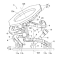
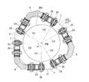
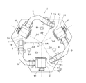
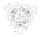
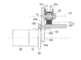
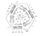
- FIG. 1 is a front view in which a part of the link operating device is omitted.
- the link actuating device includes a parallel link mechanism 1, an attitude control actuator 50 that operates the parallel link mechanism 1, and a speed reduction mechanism (not shown in FIG. 1).
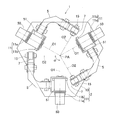
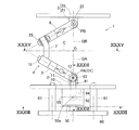
- FIG. 2 is a diagram showing one state of the parallel link mechanism 1
- FIG. 3 is a diagram showing different states of the parallel link mechanism 1.
- 2 and 3 show a state seen from the opposite direction to FIG.
- the parallel link mechanism 1 is configured such that a distal end side link hub 3 is connected to a proximal end side link hub 2 via three sets of link mechanisms 4 so that the posture can be changed. In FIG. 1, only one set of link mechanisms 4 is shown.
- the number of link mechanisms 4 may be four or more.
- 2 and 3 show the basic configuration of the parallel link mechanism 1, and when the attitude control actuator 50 and the speed reduction mechanism are attached to form a link operating device, a part of the parallel link mechanism 1 is different from the figure. Different configuration.
- each link mechanism 4 is composed of a base end side end link member 5, a front end side end link member 6, and a central link member 7, and is a four-joint chain comprising four rotary pairs.
- the link mechanism is made.
- the end link member 5 on the proximal end side and the end link member 6 on the distal end side are each formed in an L shape.
- One end of the end link member 5 on the base end side is rotatably connected to the link hub 2 on the base end side.
- the distal end side end link member 6 is rotatably connected to the distal end side link hub 3.
- the center link member 7 is rotatably connected to both ends of the end link members 5 and 6 on the proximal end side and the distal end side, respectively.
- the parallel link mechanism 1 has a structure in which two spherical link mechanisms are combined, and each rotation pair of the link hubs 2 and 3 and the end link members 5 and 6, and the end link members 5 and 6 and the central link member 7.
- the distances from the rotary pairs of the link hubs 2 and 3 and the end link members 5 and 6 and the respective spherical link centers PA and PB are the same.
- the distances from the rotary pairs of 6 and the central link member 7 and the spherical link centers PA and PB are also the same.
- the central axis of each rotational pair of the end link members 5 and 6 and the central link member 7 may have a certain crossing angle ⁇ (FIG. 1) or may be parallel.
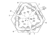
- FIG. 4 is a cross-sectional view taken along the line IV-IV in FIG. 1, and shows a central axis O1 of each rotation pair of the link hub 2 on the base end side and the end link member 5 on the base end side, the center link member 7 and the base end side
- the relationship between the center axis O2 of each rotation pair of the end link member 5 and the spherical link center PA on the base end side is shown. That is, the point where the central axis O1 and the central axis O2 intersect is the spherical link center PA on the base end side.
- FIG. 7 which is a sectional view taken along the line VII-VII of FIG.
- FIG. 1 shows the center axis O1 of each rotation pair of the link hub 3 on the distal end side and the end link member 6 on the distal end side, the center link member 7 and the end on the distal end side.
- the relationship between the center axis O2 of each rotation pair of the partial link member 6 and the spherical link center PB on the tip side is shown. That is, the point where the central axis O1 and the central axis O2 intersect is the spherical link center PB on the tip side.
- the angle ⁇ formed by the central axis O2 of the lens is 90 °, the angle ⁇ is not limited to 90 °.
- FIG. 9 is a diagram in which a set of link mechanisms 4 is expressed by a straight line.
- the parallel link mechanism 1 of this embodiment is a rotationally symmetric type, and includes a base end side link hub 2 and a base end side end link member 5, a front end side link hub 3 and a front end side end link member 6. The positional relationship is such that it is rotationally symmetric with respect to the center line C of the central link member 7.
- the central portion of each central link member 7 is located on a common orbit circle D.
- the link hub 3 on the distal end side is rotatable about two orthogonal axes with respect to the link hub 2 on the proximal end side.
- a degree mechanism is configured.
- this mechanism is a mechanism that can freely change the posture of the link hub 3 on the distal end side with respect to the link hub 2 on the proximal end side with two degrees of freedom for rotation.
- this two-degree-of-freedom mechanism is compact, the movable range of the link hub 3 on the distal end side with respect to the link hub 2 on the proximal end side can be widened.
- a straight line that passes through the spherical link centers PA and PB and intersects the link hubs 2 and 3 and the central axis O1 (FIGS. 4 and 7) of the rotation pairs of the end link members 5 and 6 at right angles is linked hubs 2 and 3.
- Center axes QA and QB, the maximum value of the bending angle ⁇ (FIG. 9) between the center axis QA of the link hub 2 on the proximal end side and the center axis QB of the link hub 3 on the distal end side is about ⁇ 90 °. be able to.
- the turning angle ⁇ (FIG.
- the bending angle ⁇ is a vertical angle in which the central axis QB of the distal end side link hub 3 is inclined with respect to the central axis QA of the proximal end side link hub 2, and the turning angle ⁇ is the proximal end side link hub.
- This is a horizontal angle at which the central axis QB of the link hub 3 on the distal end side is inclined with respect to the central axis QA of the second axis.
- the posture change of the link hub 3 on the distal end side with respect to the link hub 2 on the proximal end side is performed with the intersection O between the center axis QA of the link hub 2 on the proximal end side and the center axis QB of the link hub 3 on the distal end side as a rotation center.
- . 2 shows a state in which the central axis QA of the link hub 2 on the proximal end side and the central axis QB of the link hub 3 on the distal end side are on the same line
- FIG. 3 shows the central axis QA of the link hub 2 on the proximal end side.
- the parallel link mechanism 1 functions as a constant velocity universal joint that rotates at a constant speed with the same rotation angle on the proximal end side and the distal end side when transmitting rotation from the proximal end side to the distal end side.
- Condition 1 The angle and length of the central axis O1 of the rotational pair of the link hubs 2 and 3 and the end link members 5 and 6 in each link mechanism 4 are equal to each other.
- Condition 2 The central axis O1 of the rotational pair of the link hubs 2 and 3 and the end link members 5 and 6 and the central axis O2 of the rotational pair of the end link members 5 and 6 and the central link member 7 are on the proximal side. And at the front end side, they intersect at the spherical link centers PA and PB.
- Condition 3 The geometric shapes of the proximal end side end link member 5 and the distal end side end link member 6 are equal.
- Condition 4 The geometric shapes of the proximal end portion and the distal end portion of the central link member 7 are equal.
- Condition 5 With respect to the symmetry plane of the central link member 7, the angular positional relationship between the central link member 7 and the end link members 5 and 6 is the same on the proximal end side and the distal end side.
- the base end side link hub 2 includes a flat base end member 10 and three sets of rotation support members provided on the circumference of the base end member 10 at equal intervals. 11.
- a flat base end member 10 is provided such that the upper and lower surfaces are horizontal, and each rotation support member 11 protrudes upward from the upper surface of the base end member 10.
- the base end member 10 does not need to be flat.
- the center of the circumference where the three sets of rotation support members 11 are arranged is located on the central axis QA of the link hub 2 on the base end side.
- Each set of rotation support members 11 includes an actuator support member 11a located on the outer side in the radial direction and a speed reduction mechanism support member 11b located on the inner side.
- the actuator support member 11a and the speed reduction mechanism support member 11b are arranged at a predetermined interval from each other.
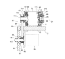
- Each rotation support member 11 is rotatably connected to one end of the end link member 5 on the base end side. Further, the attitude control actuator 50 (FIGS. 1 and 4) is supported on the actuator support member 11 a of the rotation support member 11. The speed reduction mechanism 51 (FIG. 4) is supported by the speed reduction mechanism support member 11b. A connection structure between the rotation support member 11 and the end link member 5 on the proximal end side, and a support structure for the attitude control actuator 50 and the speed reduction mechanism 51 to the rotation support member 11 will be described later.
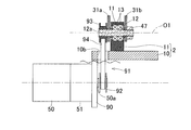
- FIG. 5 which is a partial cross-sectional view of FIG. 4, a rotating shaft 15 is attached to the other end of the end link member 5 on the base end side.
- the rotary shaft 15 is rotatably supported at one end of the central link member 7 via, for example, two bearings 16.
- the rotating shaft 15 may be rotatably supported by bringing the rotating shaft 15 into contact with one end of the central link member 7.
- the bearing 16 is a ball bearing such as a deep groove ball bearing or an angular ball bearing.
- the bearing 16 is fixed to the central link member 7 by a method such as press-fitting, bonding, or caulking. The same applies to the types and installation methods of the bearings provided in other rotating pairs.
- the rotary shaft 15 may be rotatably supported by bringing the rotary shaft 15 into contact with the central link member 7 in a rotatable manner.
- the link hub 3 on the distal end side includes a distal end member 20 and three rotation support members 21 provided on the circumference of the distal end member 20 at equal intervals. Consists of.
- the tip member 20 has a flat plate shape, for example.
- the center of the circumference where the three rotation support members 21 are arranged is located on the central axis QB of the link hub 3 on the distal end side.
- the link hub 3 on the distal end side has a circular through hole 20 a inside the three sets of rotation support members 21.
- a rotation shaft 22 that intersects the central axis QB (FIG. 1) of the link hub 3 on the distal end side is rotatably supported by each rotation support member 21 via a bearing 23.
- the rotating shaft 22 is attached to one end of the end link member 6 on the distal end side.
- a rotating shaft 25 is attached to the other end of the end link member 6 on the front end side.
- the rotating shaft 25 is rotatably supported on the other end of the central link member 7 via, for example, two bearings 26.
- the rotating shaft 25 may be rotatably supported by bringing the rotating shaft 25 into contact with the other end of the central link member 7 in a freely rotatable manner.
- FIG. 5 is a partial sectional view of FIG. 4 and FIG. 8 which is a partial view of FIG. Since the base end side end link member 5 and the front end side end link member 6 have the same configuration except for a part thereof, the base end side end link member 5 will be described as a representative here.
- the code of the corresponding location is shown in parentheses. The portions where the configurations of the base end side and the end side end link members 5 and 6 are different will be described as appropriate.
- the end link member 5 (6) is composed of one bending portion 30, the rotation connecting portion 31 ⁇ / b> A on the link hub side located at both ends of the bending portion 30, and the central link side.
- the rotation connecting portion 31B is composed of a pair of rotation coupling bodies 31a and 31b fixed to the outer side surface and the inner side surface of the end portion of the bending portion 30, respectively.
- the curved portion 30 is, for example, a cast product of a metal material.
- the bending portion 30 has a shape bent at a predetermined angle ⁇ (see FIG. 4; 90 ° in this example).
- the bending angle ⁇ can be arbitrarily determined.
- one bolt screw hole 32 penetrating between the outer surface and the inner surface is provided.
- Two positioning holes 33 located on both sides of the bolt screw hole 32 are provided at both ends of the bending portion 30.
- Rotation coupling bodies 31a and 31b of the rotation coupling portions 31A and 31B are made into a predetermined shape by processing a plate-like member having a constant thickness such as a metal plate or the like.
- the rotationally connected bodies 31a and 31b (FIG. 5) of the rotationally connecting portion 31A on the link hub side in the end link member 5 on the proximal end side are bent as will be described later.
- the other rotary coupling bodies 31a and 31b have a flat plate shape.
- Each rotation coupling body 31a, 31b is provided with one bolt insertion hole 34 corresponding to the bolt screw hole 32 of the bending portion 30 and two positioning holes 35 corresponding to the positioning hole 33 of the bending portion 30. It has been.
- any of the rotary shafts 15, 22, and 25 is included in the rotary coupling bodies 31 a and 31 b used in the rotary coupling portions 31 A and 31 B other than the rotary coupling portion 31 A on the link hub side of the end link member 5 on the proximal end side.
- a through-hole 36 through which is inserted is provided. If a plate-like member having a simple shape and a constant thickness is used as the material of the rotary coupling bodies 31a and 31b, it can be manufactured at low cost and is excellent in mass productivity. In particular, when the material is a metal plate, the contour shape and the processing of the holes 34, 35, and 36 are easy.
- the positioning pins 37 are inserted into the positioning holes 33 of the bending portion 30 and the positioning holes 35 of the outer and inner rotary connecting bodies 31a and 31b.
- the bolts 38 are inserted into the bolt insertion holes 34 of the rotary coupling bodies 31 a and 31 b from the outside and the inside, respectively, and the screw portions of the bolts 38 are screwed into the bolt screw holes 32 of the bending portion 30. That is, the outer and inner rotary coupling bodies 31 a and 31 b are individually fixed to the bending portion 30 by different bolts 38 while being positioned by the common positioning pin 37.
- the assembly becomes easy and the variation in the assembly accuracy by the operator is reduced.
- the accuracy of the positional relationship between the bending portion 30 and the rotary coupling bodies 31a and 31b is improved, a smooth operation of the parallel link mechanism 1 can be realized.
- the link hub side rotation connecting portion 31A in the base end side end link member 5 is formed by bending a pair of outer and inner rotation connecting bodies 31a and 31b, for example, by bending. Yes.
- the mutual interval between the portions connected to the rotation support member 11 is wider than the mutual interval between the portions fixed to the bending portion 30.
- the outer rotation coupling body 31 a is disposed inside the actuator support member 11 a of the rotation support member 11.
- the inner rotation coupling body 31 b is disposed inside the speed reduction mechanism support member 11 b of the rotation support member 11.
- the rotation connecting portion 31 ⁇ / b> A of the end link member 5 on the proximal end side is assembled to the rotation support member 11 together with the attitude control actuator 50 and the speed reduction mechanism 51. Specifically, it is assembled as follows.
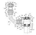
- the attitude control actuator 50 is fixed to the outer surface of the actuator support member 11 a of the rotation support member 11.
- the attitude control actuator 50 is, for example, a rotary motor.
- the rotation output shaft 50a of the attitude control actuator 50 passes through the actuator support member 11a and the outer rotary coupling body 31a and extends inward from the rotary coupling body 31a.
- the rotation output shaft 50a is rotatably supported by a bearing 61 provided on the rotation coupling body 31a.
- the speed reduction mechanism 51 is fixed to the outer surface of the speed reduction mechanism support member 11b of the rotation support member 11.
- the speed reduction mechanism 51 is configured such that the input shaft 51a and the output shaft 51b are on the same axis.
- the input shaft 51a and the output shaft 51b are on the same axis as the central axis O1 of the rotational pair of the link hub 2 on the base end side and the end link member 5 on the base end side.
- the input shaft 51 a of the speed reduction mechanism 51 is the same axis as the rotation output shaft 50 a of the attitude control actuator 50.
- the input shaft 51a and the output shaft 51b are rotatably supported on the housing of the speed reduction mechanism 51 by bearings 62 and 63, respectively.
- a spacer 64 is interposed between the speed reduction mechanism 51 and the actuator support member 11a.
- a flange 65 is fixed to the tip of the output shaft 51 b of the speed reduction mechanism 51, and a cylindrical member 66 is fixed to the outer periphery of the flange 65.
- the cylindrical member 66 extends inwardly through the inner diameter hole 67 of the speed reduction mechanism support member 11b, and the tip end surface thereof is coupled to the inner rotary coupling body 31b by a plurality of bolts 68.
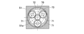
- the speed reduction mechanism 51 is a planetary gear mechanism.
- the speed reduction mechanism 51 including a planetary gear mechanism has a sun gear 70, a plurality of planetary gears 71, a carrier 72, and an internal gear 73.
- the sun gear 70 is coupled to the input shaft 51a and the carrier 72 is coupled to the output shaft 51b, the rotation of the input shaft 51a is decelerated in the same direction and output to the output shaft 51b.
- the rotation support member 21 is arranged between a pair of outer and inner rotation coupling bodies 31 a and 31 b in the rotation coupling section 31 ⁇ / b> A on the link hub side in the end link member 6 on the distal end side. . Then, the end link member 6 and the rotation support member 21 are rotatably connected to each other via the rotation shaft 22. Specifically, the connections are made as follows.
- the rotary shaft 22 has a head portion 22a having a larger diameter than other portions at the outer diameter end, and a male screw portion 22b at the inner diameter end.
- the rotary shaft 22 is inserted from the male screw portion 22b side into the outer rotary coupling body 31a, the spacer 45, the inner ring of the two bearings 23, the spacer 46, and the through holes of the inner rotary coupling body 31b in order.
- a nut 47 is screwed onto 22b.
- the head 22a of the rotating shaft 22 and the nut 47 sandwich the pair of rotary coupling bodies 31a and 31b, the inner ring of the two bearings 23, and the two spacers 45 and 46, thereby preloading the bearing 23.
- the end link member 6 and the rotation support member 21 are rotatably connected to each other.
- the rotation link 31B on the center link side of the end link member 5 (6) is between the pair of rotation links 31a and 31b on the outside and inside.
- One end (the other end) is arranged.
- the end link member 5 (6) and the central link member 7 are rotatably connected to each other via the rotary shaft 15 (25).
- the connections are made as follows.
- the rotary shaft 15 (25) has a head portion 15a (25a) having a larger diameter than other portions at the outer diameter end, and a male screw portion 15b (25b) at the inner diameter end. From the male screw portion 15b (25b) side, the rotary shaft 15 (25) is connected to the outer rotary coupling body 31a, the spacer 45, the inner ring of the two bearings 16 (26), the spacer 46, and the inner rotary coupling body 31b. The nuts 47 are inserted through the through holes in order, and the nuts 47 are screwed into the male screw portions 15b (25b).
- the head 15a (25a) of the rotary shaft 15 (25) and the nut 47 sandwich the pair of rotary coupling bodies 31a and 31b, the inner ring of the two bearings 16 (26), and the two spacers 45 and 46.
- the end link member 5 (6) and the central link member 7 are rotatably connected to each other in a state where a preload is applied to the bearing 16 (26).
- This link actuating device operates the parallel link mechanism 1 by rotationally driving each attitude control actuator 50. Specifically, when the attitude control actuator 50 is rotationally driven, the rotation is decelerated via the speed reduction mechanism 51, and the inner rotational coupling body of the rotational hub 31 ⁇ / b> A on the link hub side of the end link member 5 on the proximal end side. 31b. Thereby, the angle of the end link member 5 on the base end side is changed, and the attitude of the link hub 3 on the distal end side with respect to the link hub 2 on the base end side is changed.
- the parallel link mechanism 1 has a compact structure because the distal end side link hub 3 is connected to the proximal end side link hub 2 via three sets of four-link chains 3 so that the posture can be changed. Nevertheless, it can operate in a wide range of operation with high speed and high accuracy.
- Each of the rotation coupling portions 31A and 31B of the end link members 5 and 6 includes a pair of rotation coupling bodies 31a and 31b. Since the rotation coupling bodies 31a and 31b are made of a metal plate that is detachably attached to the bending portion 30, the rotation coupling bodies 31a and 31b can be manufactured at low cost and with high productivity by sheet metal processing. The rotary coupling bodies 31a and 31b can be made to correspond to the difference in the size of the link actuator only by changing the size of the metal plate as the material. For this reason, it is possible to easily change the size of the link operating device.
- each part can be made into a simple shape, the processing cost can be suppressed, and the mass productivity can be suppressed. Will improve. If the rotary coupling bodies 31a and 31b of the rotary coupling portions 31A and 31B have the same shape, the parts can be shared, and the cost is low and the mass productivity is good. However, the thickness and shape of the rotary coupling bodies 31a and 31b may be varied depending on the location where the rotary coupling bodies 31a and 31b are used and the required strength.
- the output shaft 51b of the speed reduction mechanism 51 is fixed to the inner rotation coupling body 31b, and the input shaft 51a of the speed reduction mechanism 51 is rotatably supported by the outer rotation coupling body 31a, thereby a pair of rotation coupling bodies 31a and 31b. It is possible to arrange the speed reduction mechanism 51 between them. Thereby, the speed reduction mechanism 51 can be installed on the radially outer side of the parallel link mechanism 1 without projecting, and a more compact configuration can be realized. That is, the speed reduction mechanism 51 in which the input shaft 51a and the output shaft 51b are on the same axis can be installed without increasing the radial dimension. In addition, if the speed reduction mechanism 51 is disposed between the pair of rotation coupling bodies 31a and 31b, the speed reduction mechanism 51 has a structure for connecting the pair of rotation coupling bodies 31a and 31b, which is advantageous in improving rigidity.
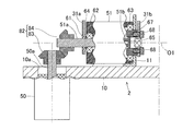
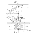
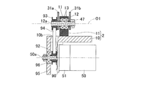
- This link actuator differs from the embodiment shown in FIGS. 1, 4, and 5 in the arrangement of the attitude control actuator 50. That is, in the embodiment, the rotation output shaft 50a of the attitude control actuator 50 is coaxial with the input shaft 51a of the deceleration mechanism 51, whereas in this embodiment, the rotation output shaft 50a of the attitude control actuator 50 and the deceleration are reduced.
- the input shaft 51a of the mechanism 51 is a separate axis and is arranged perpendicular to each other.
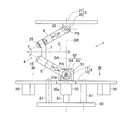
- the base end member 10 is supported on the upper ends of a plurality of support columns 81 provided on the base plate 80.
- the attitude control actuator 50 is fixedly provided on the bottom surface of the base end member 10, and the rotation output shaft 50 a passes through the opening 10 a of the base end member 10 and protrudes upward.
- the rotation output shaft 50 a extending in the vertical direction is connected to the horizontal input shaft 51 a of the speed reduction mechanism 51 via a gear mechanism 82.
- the gear mechanism 82 includes a drive-side bevel gear 83 attached to the rotation output shaft 50a and a driven-side bevel gear 84 attached to the input shaft 51a.
- the posture control actuator 50 when the posture control actuator 50 is provided so that the rotation output shaft 50a of the posture control actuator 50 and the input shaft 51a of the speed reduction mechanism 51 are orthogonal to each other, the base end side link hub 2 and the base end are provided.
- the other parts are not arranged around the rotating pair with the end link member 5 on the side, and the parallel link mechanism 1 can take a wide operating range. Others are the same as the said embodiment.
- the link actuating device is configured such that the rotation axis of the proximal end side link hub 2 and the proximal end side end link member 5 with respect to the proximal end member 10 and the output of the attitude control actuator 50 are the same.
- the shaft 50a is disposed on the opposite side.
- the posture control actuator 50 is arranged at the above position, there is no component of the parallel link mechanism 1 on the surface of the base member 10 opposite to the side where each link mechanism 4 is located.
- the degree of freedom in designing the arrangement of the actuator 50 is high. Others are the same as the said embodiment.
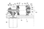
- the gear mechanism 82 shown in FIG. 12 has a configuration in which the driven bevel gear 84 is positioned inside the drive-side bevel gear 83. However, like the gear mechanism 82 shown in FIG. It is good also as a structure in which the bevel gear 84 of the driven side outside is located. In the configuration of FIG. 13, the attitude control actuator 50 can be arranged on the center side in the radial direction, and the parallel link mechanism 1 can be made more compact than the configuration of FIG. 12.
- the attitude control actuator 50 is arranged so that the rotation output shaft 50 a of the attitude control actuator 50 is parallel to the input shaft 51 a of the speed reduction mechanism 51.
- the rotation is transmitted from the rotation output shaft 50a to the input shaft 51a by a belt-type power transmission mechanism 91.
- the base end member 10 is supported on the upper ends of a plurality of support columns 81 provided on the base plate 80.
- FIG. 16 which is a cross-sectional view taken along the line XVI-XVI of FIG. 14, the attitude control actuator 50 with the rotary output shaft 50a placed horizontally on the actuator support member 90 fixed to the bottom surface of the base end member 10.
- the power transmission mechanism 91 includes a driving side timing pulley 92 attached to the rotation output shaft 50a of the attitude control actuator 50, a driven side timing pulley 93 attached to the input shaft 51a of the speed reduction mechanism 51, and both timings.
- a timing belt 94 hung on pulleys 92 and 93. The timing belt 94 passes through the opening 10 a of the base end member 10.
- the rotation output shaft support member 95 is provided in a suspended posture on the bottom surface of the base end member 10.
- a rotation output shaft 50 a of the attitude control actuator 50 is rotatably supported by a bearing 96 provided on the rotation output shaft support member 95.
- the bearing 96 is axially formed by a spacer 97 interposed between an inner ring (not shown) of the bearing 96 and a timing pulley 92 on the driving side, and a nut 98 screwed to a tip screw portion of the rotary output shaft 50a. Is positioned.
- the base-side link hub 2 and the base Other parts are not arranged around the rotation pair with the end link member 5 on the end side, and the parallel link mechanism 1 can take a wide operation range.
- the power transmission mechanism 91 does not necessarily have a configuration using the timing belt 94.
- the base end member 10 Since the base end member 10 has a flat plate shape, the base end member 10 is provided with a plurality of rotation support members 11 without increasing the dimension in the direction along the central axis QA of the base end side link hub 2. Can be provided.
- the output shaft 50 a of the attitude control actuator 50 is parallel to the base end member 10, the output shaft 50 a of the attitude control actuator 50 can be provided close to the base end member 10 as a whole.
- the central axis O1 of the rotating pair of the base end side link hub 2 and the base end side end link member 5 is parallel to the base end member 10, the central axis O1 is entirely connected to the base end member. 10 can be provided.
- the dimension of the direction in alignment with the central axis QA of the link hub 2 of the base end side of the whole link actuator can be made compact.
- the base end member 10 may not be entirely flat. Even when the base end member 10 is not flat, the arrangement surface of the base end member 10 on which the plurality of rotation support members 11 are disposed and the output shaft 50a and / or the central axis O1 of the rotation pair are provided. What is necessary is just to be parallel.
- an actuator support member 90 is provided at a position slightly inside the outer peripheral edge of the bottom surface of the base end member 10, and the attitude control actuator 50 and the speed reduction mechanism 51 are attached to the inner side surface of the actuator support member 90. Yes.
- the output shaft 50a of the attitude control actuator 50 extends to the outer diameter side.
- An actuator rotation support member 95 is provided on the outer peripheral edge of the bottom surface of the base end member 10, and the output shaft 50 a is rotatably supported by the actuator rotation support member 95 via a bearing 96.
- each posture control actuator 50 can be accommodated within a range below the base end member 10 so that it does not protrude outward from the base end member 10. Others are the same as the said embodiment.
- the output shaft 50a of the attitude control actuator 50 is connected to the rotation pair of the base end side link hub 2 and the base end side end link member 5.
- the central axis O1 and the plane formed by the central axis QA of the link hub 2 on the proximal end side may be arranged offset in parallel.
- the posture control actuators 50 By arranging the posture control actuators 50 so as to be offset in this way, even if the posture control actuators 50 are long in the axial direction of the output shaft 50a, the posture control actuators 50 can be prevented from interfering with each other. it can.
- a space 78 for passing wiring or the like can be widened in the central portion in the radial direction of the portion where the attitude control actuator 50 is disposed. Accordingly, the through hole 10a of the base end member 10 is also enlarged. Others are the same as the third embodiment.
- the center of the circumference where the three rotation support members 11 are arranged is located on the central axis QA of the link hub 2 on the proximal end side.
- a through hole 10 a may be formed at the center of the row of the rotation support members 11.
- the center of the through hole 10a is also located on the central axis QA of the link hub 2 on the proximal end side.
- the through hole 10a is provided in the central portion of the base member 10 where the plurality of rotation support members 11 are arranged, the through hole 10a can be provided with a wiring or the like, and the wiring or the like can be easily routed.
- this link actuating device also has the posture control actuator 50 arranged so that the rotation output shaft 50 a of the posture control actuator 50 is parallel to the input shaft 51 a of the speed reduction mechanism 51. Has been.
- the difference from the embodiment of FIGS. 14 to 16 is that the rotation is transmitted from the rotation output shaft 50a to the input shaft 51a by the gear-type power transmission mechanism 101.
- the posture control actuator 50 is provided on the actuator support member 90 in a posture in which the rotation output shaft 50a is horizontal, as in the embodiment of FIGS.
- the gear-type power transmission mechanism 101 includes a drive gear 102 attached to the rotation output shaft 50 a of the attitude control actuator 50, a counter gear 103 provided in the opening 10 a of the base end member 10, and an input of the speed reduction mechanism 51. It is comprised with the driven gear 104 attached to the axis
- Each of the gears 102, 103, and 104 is a spur gear.
- the power transmission mechanism 101 in the figure has three gears, but it may be other than three.
- the rotation is transmitted in the same direction from the rotation output shaft 50a of the attitude control actuator 50 to the input shaft 51a of the speed reduction mechanism 51, but may be transmitted in the opposite direction. Others are the same as the said embodiment.
- the speed reduction mechanism is provided, and the base end side end link member includes a curved portion curved at an arbitrary angle and a pair of rotary coupling bodies arranged at one end of the curved portion and spaced apart from each other.
- the speed reduction mechanism has an input shaft and an output shaft on the same axis, and the shafts of the input shaft and the output shaft are interposed between the pair of rotary connections.
- the base end side link hub and the base end side end link member are arranged so as to coincide with the central axis of the rotation pair, and the output shaft of the speed reduction mechanism is one of the pair of rotary coupling bodies.
- the present invention does not require that the input shaft of the speed reduction mechanism is rotatably supported by the other rotational coupling body of the pair of rotational coupling bodies, and is fixed to the rotational coupling body.
- a link actuator according to an application mode not included in the range will be described.
- This application mode includes the following modes 1 to 6. According to the link actuating device according to this application mode, it is possible to operate in a wide range of operation with high speed and high accuracy, the radial dimension is compact, and the degree of freedom in designing the arrangement of the attitude control actuator is high.
- the link hub on the distal end side is connected to the link hub on the proximal end side through three or more sets of link mechanisms so that the posture can be changed, and each link mechanism includes the link hub on the proximal end side and the link hub on the distal end side.
- End link members on the base end side and the tip end side one end of which is rotatably connected to the link hub, and a center on which both ends are rotatably connected to the other ends of the end link members on the base end side and the tip end side, respectively.
- a posture control actuator that has two or more link mechanisms out of the three or more link mechanisms and arbitrarily changes the posture of the distal link hub with respect to the proximal link hub.
- the link actuating device provided with The link hub on the base end side has a base end member that supports the link mechanisms, With respect to the base end member, a central axis of a rotation pair of the base end side link hub and the base end side end link member and an output shaft of the attitude control actuator are arranged on opposite sides.
- a link actuating device characterized in that: [Aspect 2] In the link actuating device according to aspect 1, the base end side link hub is provided to protrude from the base end member to the front end side, and each of the base end side end link members is rotatably supported. A rotation support member; The link actuating device, wherein the output shaft of the attitude control actuator is parallel to an arrangement surface of the plurality of rotation support members in the base end member.
- the base end side link hub is provided to protrude from the base end member to the front end side, and rotatably supports the base end side end link members.
- Link actuator that is parallel.
- the link actuating device wherein the proximal end side link hub and the central axis of each rotation pair of the proximal end side end link member, and the proximal end side end link member and the central link member
- the point at which the central axis of each rotation pair intersects is referred to as the spherical link center on the base end side, passes through the spherical link center on the base end side, and the base end side link hub and the base end side end link member
- the straight line that intersects the central axis of each rotation pair at right angles is referred to as the central axis of the link hub on the base end side
- the output shaft of the attitude control actuator is a plane formed by the central axis of the rotation pair of the base end side link hub and the base end side end link member, and the central axis of the base end side link hub
- a link actuating device arranged offset in parallel.
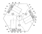
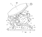
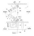
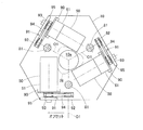
- FIG. 24 is a front view in which a part of the link operating device is omitted.
- the link actuating device includes a parallel link mechanism 1 and a plurality of attitude control actuators 50 that actuate the parallel link mechanism 1.
- the parallel link mechanism 1 is supported vertically on the upper ends of a plurality of support columns 81 installed on the base plate 80.
- FIG. 25 is a diagram showing one state of the parallel link mechanism 1
- FIG. 26 is a diagram showing different states of the parallel link mechanism 1.
- 25 and 26 show a state seen from the opposite direction to FIG.
- the parallel link mechanism 1 is configured such that a distal end side link hub 3 is connected to a proximal end side link hub 2 via three sets of link mechanisms 4 so that the posture can be changed. In FIG. 24, only one set of link mechanisms 4 is shown. The number of link mechanisms 4 may be four or more.
- 25 and 26 show the basic configuration of the parallel link mechanism 1, and when the attitude control actuator 50 and the like are attached to form a link operating device, a part of the parallel link mechanism 1 is different from the drawing. It becomes.
- each link mechanism 4 is composed of a base end side end link member 5, a front end side end link member 6, and a central link member 7, and is a four-bar chain consisting of four rotary pairs.
- the link mechanism is made.
- the end link members 5 and 6 on the proximal end side and the distal end side are L-shaped, and one ends thereof are rotatably connected to the link hub 2 on the proximal end side and the link hub 3 on the distal end side, respectively.
- the center link member 7 is rotatably connected to both ends of the end link members 5 and 6 on the proximal end side and the distal end side, respectively.
- FIG. 27 which is a sectional view taken along the line XXVII-XXVII of FIG. 24, shows the central axis O1 of each rotation pair of the link hub 2 on the base end side and the end link member 5 on the base end side, the center link member 7 and the base end side.
- the relationship between the center axis O2 of each rotation pair of the end link member 5 and the spherical link center PA on the base end side is shown. That is, the point where the central axis O1 and the central axis O2 intersect is the spherical link center PA on the base end side.
- FIG. 30, which is a sectional view taken along the line XXX-XXX of FIG.
- FIGS. 27 and 30 shows the central axis O1 of each rotation pair of the link hub 3 on the distal end side and the end link member 6 on the distal end side, the central link member 7 and the end on the distal end side.
- the relationship between the center axis O2 of each rotation pair of the partial link member 6 and the spherical link center PB on the tip side is shown. That is, the point where the central axis O1 and the central axis O2 intersect is the spherical link center PB on the tip side.
- the angle ⁇ formed by the central axis O2 of the angle ⁇ is 90 °, the angle ⁇ may be other than 90 °.
- the link hub 2 on the base end side is provided with a flat plate base end member 10 that supports each link mechanism 4 and an equal distribution on the circumference of the base end member 10. And three rotation support members 11.
- a flat base end member 10 is provided such that the upper and lower surfaces are horizontal, and each rotation support member 11 protrudes upward from the upper surface of the base end member 10.
- the parallel link mechanism 1 is supported by the base member 80 by connecting the upper end of the column 81 to the bottom surface of the base end member 10.
- the base end member 10 does not need to be flat.
- the center of the circumference where the three rotation support members 11 are arranged is located on the central axis QA of the link hub 2 on the proximal end side.
- a through hole 10 a is formed at the center of the rotation support members 11.
- the center of the through hole 10a is also located on the central axis QA of the link hub 2 on the proximal end side.
- FIG. 28 which is a sectional view taken along the line XXVIII-XXVIII of FIG. 24, one end of the end link member 5 on the base end side is rotatably connected to each rotation support member 11.
- the rotation shaft 12 is rotatably supported by the rotation support member 11 via the two bearings 13, and one end of the end link member 5 on the proximal end side is connected to the rotation shaft 12.
- the other end of the end link member 5 on the base end side is connected to one end of the central link member 7.
- the rotation shaft 15 is rotatably supported by the central link member 7 via two bearings 16, and the other end of the end link member 5 on the proximal end side is connected to the rotation shaft 15. .
- the bearings 13 and 16 are ball bearings such as deep groove ball bearings and angular ball bearings, for example. These bearings 13 and 16 are fixed to the rotation support member 11 or the central link member 7 by a method such as press fitting, adhesion, or caulking. Instead of using the bearings 13 and 16 as in this example, the rotary shafts 12 and 15 are rotatably contacted with the rotary support member 11 or the central link member 7 so that the rotary shafts 12 and 15 are rotatably supported. Also good. The same applies to the types and installation methods of the bearings provided in other rotating pairs.
- the link hub 3 on the distal end side includes a flat plate-shaped distal end member 20 and three rotational supports provided on the circumference of the distal end member 20 at equal intervals. It is comprised with the member 21.
- FIG. The center of the circumference where the three rotation support members 21 are arranged is located on the central axis QB of the link hub 3 on the distal end side.
- the tip member 20 may not be flat.
- FIG. 31 which is a XXXI-XXXI sectional view of FIG. 24, one end of the end link member 6 on the distal end side is rotatably connected to each rotation support member 21.
- the rotation shaft 22 is rotatably supported by the rotation support member 21 via two bearings 23, and one end of the end link member 6 on the distal end side is connected to the rotation shaft 22.
- the other end of the end link member 6 on the front end side is connected to the other end of the central link member 7.
- the rotary shaft 25 is rotatably supported by the central link member 7 via two bearings 26, and the other end of the end link member 6 on the distal end side of the rotary shaft 25 is connected.
- end link members 5 and 6 will be described with reference to FIGS. Since the end link members 5 and 6 on the proximal end side and the distal end side have the same configuration except for a part, the end link member 5 on the proximal end side will be described as a representative here, and the end link on the distal end side will be described. For 6, the code of the corresponding location is shown in parentheses. The parts having different configurations of the end link members 5 and 6 on the proximal end side and the distal end side will be described as needed.
- each rotation connection part 31A, 31B consists of a pair of rotation connection body 31a, 31b each fixed to the outer surface and inner surface of the edge part of the bending part 30.
- the curved portion 30 is, for example, a cast product of a metal material, and has a shape curved at a predetermined angle ⁇ (see FIGS. 27 and 30; in this example, 90 °).
- the bending angle ⁇ can be arbitrarily determined.
- one bolt screw hole 32 penetrating between the outer surface and the inner surface and two positioning holes 33 positioned on both sides of the bolt screw hole 32 are provided.
- Rotation coupling bodies 31a and 31b of the rotation coupling portions 31A and 31B are made into a predetermined shape by processing a plate-like member having a constant thickness such as a metal plate or the like.
- the shape of the rotary coupling bodies 31a and 31b is, for example, an elongated straight line, and one bolt insertion hole 34 corresponding to the bolt screw hole 32 of the bending portion 30 and two positioning positions corresponding to the positioning hole 33 of the bending portion 30.
- a hole 35 and a through hole 36 through which any one of the rotary shafts 12, 15, 22, and 25 is inserted are provided.
- a plate-like member having a simple shape and a constant thickness is used as the material of the rotary coupling bodies 31a and 31b, it can be manufactured at low cost and is excellent in mass productivity. In particular, when the material is a metal plate, the contour shape and the processing of the holes 34, 35, and 36 are easy.
- the positioning pins 37 are inserted into the positioning holes 33 of the bending portion 30 and the positioning holes 35 of the outer and inner rotary connecting bodies 31a and 31b.
- the bolts 38 are inserted into the bolt insertion holes 34 of the rotary coupling bodies 31 a and 31 b from the outside and the inside, respectively, and the screw portions of the bolts 38 are screwed into the bolt screw holes 32 of the bending portion 30. That is, the outer and inner rotary coupling bodies 31 a and 31 b are individually fixed to the bending portion 30 by different bolts 38 while being positioned by the common positioning pin 37.
- the assembly becomes easy and the variation in the assembly accuracy by the operator is reduced.
- the accuracy of the positional relationship between the bending portion 30 and the rotary coupling bodies 31a and 31b is improved, a smooth operation of the parallel link mechanism 1 can be realized.
- the rotation support member 11 is disposed between a pair of outer and inner rotation connecting bodies 31a and 31b.
- the end link member 5 and the rotation support member 11 are connected to each other via the rotation shaft 12 so as to be rotatable. Specifically, they are connected as follows.
- the rotary shaft 12 has a pulley mounting portion 12a for attaching a timing pulley 93 to be described later to the outer diameter end, and has a male screw portion 12b at the inner diameter end.
- the rotary shaft 12 is inserted from the male screw portion 12b side into the outer rotary coupling body 31a, the spacer 45, the inner ring of the two bearings 13, the spacer 46, and the through holes of the inner rotary coupling body 31b in order.
- a nut 47 is screwed to 12b.
- the timing pulley 93 and the nut 47 sandwich the pair of rotary coupling bodies 31a and 31b, the inner ring of the two bearings 13, and the two spacers 45 and 46, thereby applying a preload to the bearing 13.
- the end link member 6 and the rotation support member 21 are rotatably connected to each other.
- the timing pulley 93 is rotatable with respect to the outer rotary coupling body 31a.
- the rotation support member 21 is disposed between a pair of outer and inner rotation coupling bodies 31 a and 31 b in the rotation coupling section 31 ⁇ / b> A on the link hub side in the end link member 6 on the distal end side. . Then, the end link member 6 and the rotation support member 21 are rotatably connected to each other via the rotation shaft 22. Specifically, they are connected as follows.
- the rotary shaft 22 has a head portion 22a having a larger diameter than other portions at the outer diameter end, and a male screw portion 22b at the inner diameter end.
- the rotary shaft 22 is inserted from the male screw portion 22b side into the outer rotary coupling body 31a, the spacer 45, the inner ring of the two bearings 23, the spacer 46, and the through holes of the inner rotary coupling body 31b in order.
- a nut 47 is screwed onto 22b.
- the head 22a of the rotating shaft 22 and the nut 47 sandwich the pair of rotary coupling bodies 31a and 31b, the inner ring of the two bearings 23, and the two spacers 45 and 46, thereby preloading the bearing 23.
- the end link member 6 and the rotation support member 21 are rotatably connected to each other.
- the rotation link 31B on the center link side of the end link member 5 (6) is between the pair of rotation links 31a and 31b on the outside and inside.
- One end (the other end) is arranged.
- the end link member 5 (6) and the central link member 7 are rotatably connected to each other via the rotary shaft 15 (25).
- the connections are made as follows.
- the rotary shaft 15 (25) has a head portion 15a (25a) having a larger diameter than other portions at the outer diameter end, and a male screw portion 15b (25b) at the inner diameter end. From the male screw portion 15b (25b) side, the rotary shaft 15 (25) is connected to the outer rotary coupling body 31a, the spacer 45, the inner ring of the two bearings 16 (26), the spacer 46, and the inner rotary coupling body 31b. The nuts 47 are inserted through the through holes in order, and the nuts 47 are screwed into the male screw portions 15b (25b).
- the head 15a (25a) of the rotary shaft 15 (25) and the nut 47 sandwich the pair of rotary coupling bodies 31a and 31b, the inner ring of the two bearings 16 (26), and the two spacers 45 and 46.
- the end link member 5 (6) and the central link member 7 are rotatably connected to each other in a state where a preload is applied to the bearing 16 (26).
- FIG. 29 is a sectional view taken along line XXIX-XXIX in FIG.
- An actuator support member 90 is provided projecting downward from the outer peripheral edge of the bottom surface of the base end member 10, and the posture control actuator 50 and the accompanying speed reduction mechanism 51 are attached to the outer surface of the actuator support member 90. Yes. Specifically, the attitude control actuator 50 and the attached speed reduction mechanism 51 are attached to the actuator support member 90 in the speed reduction mechanism 51.
- the attitude control actuator 50 is a rotary motor, and its output shaft 50 a extends horizontally through the actuator support member 90 to the inside of the actuator support member 90. Then, rotation is transmitted from the output shaft 50 a of the attitude control actuator 50 to the rotating shaft 12 by a belt-type power transmission mechanism 91.
- the belt-type power transmission mechanism 91 includes a driving-side timing pulley 92 attached to the output shaft 50a, a driven-side timing pulley 93 attached to the pulley attaching portion 12a of the rotating shaft 12, and both timing pulleys 92, 93. And a timing belt 94 hung on the belt.
- the timing belt 94 is passed through an opening 10 b opened in the base end member 10.
- This link actuating device operates the parallel link mechanism 1 by rotationally driving each attitude control actuator 50. Specifically, when the attitude control actuator 50 is rotationally driven, the rotational power is decelerated by the reduction mechanism 51, and the reduced rotational power is transmitted to the rotary shaft 12 via the power transmission mechanism 91. Thereby, the angle of the end link member 5 on the base end side is changed, and the attitude of the link hub 3 on the distal end side with respect to the link hub 2 on the base end side is changed.
- the parallel link mechanism 1 has a compact structure because the distal end side link hub 3 is connected to the proximal end side link hub 2 via three sets of four-link chains 3 so that the posture can be changed. Nevertheless, it can operate in a wide range of operation with high speed and high accuracy.
- Each of the rotation coupling portions 31A and 31B of the end link members 5 and 6 includes a pair of rotation coupling bodies 31a and 31b. Since the rotation coupling bodies 31a and 31b are made of a metal plate that is detachably attached to the bending portion 30, the rotation coupling bodies 31a and 31b can be manufactured at low cost and with high productivity by sheet metal processing. The rotary coupling bodies 31a and 31b can be made to correspond to the difference in the size of the link actuator only by changing the size of the metal plate as the material. For this reason, it is possible to easily change the size of the link operating device.
- each part can be made into a simple shape, the processing cost can be suppressed, and the mass productivity can be suppressed. Will improve. If the rotary coupling bodies 31a and 31b of the rotary coupling portions 31A and 31B have the same shape, the parts can be shared, and the cost is low and the mass productivity is good. However, the thickness and shape of the rotary coupling bodies 31a and 31b may be varied depending on the location where the rotary coupling bodies 31a and 31b are used and the required strength.
- This link actuating device is configured such that the proximal end side link hub 2 and the proximal end side end link member 5 have a rotational axis of the central axis O1 and the attitude control actuator 50 output shaft 50a. Are disposed on opposite sides of each other. As a result, the posture control actuator 50 and the components associated with the posture control actuator 50 are not arranged around the rotation pair of the base end side link hub 2 and the base end side end link member 5. The For this reason, the attitude control actuator 50 and the parallel link mechanism 1 are unlikely to interfere with each other, and the parallel link mechanism 1 can take a wide operating range while having a compact radial dimension. Further, since the posture control actuator 50 is arranged at the above position, there is no component of the parallel link mechanism 1 on the surface of the base member 10 opposite to the side where each link mechanism 4 is located. The degree of freedom in designing the arrangement of the actuator 50 is high.
- the base end member 10 Since the base end member 10 has a flat plate shape, the base end member 10 is provided with a plurality of rotation support members 11 without increasing the dimension in the direction along the central axis QA of the base end side link hub 2. Can be provided.
- the output shaft 50 a of the attitude control actuator 50 is parallel to the base end member 10, the output shaft 50 a of the attitude control actuator 50 can be provided close to the base end member 10 as a whole.
- the central axis O1 of the rotating pair of the base end side link hub 2 and the base end side end link member 5 is parallel to the base end member 10, the central axis O1 is entirely connected to the base end member. 10 can be provided. From these things, the dimension of the direction in alignment with the central axis QA of the link hub 2 of the base end side of the whole link actuator can be made compact.
- the through hole 10a is provided in the central portion of the base member 10 where the plurality of rotation support members 11 are arranged, the through hole 10a can be provided with a wiring or the like, and the wiring or the like can be easily routed.
- a power transmission mechanism 101 that transmits rotation from the output shaft 50a of the attitude control actuator 50 to the rotary shaft 12 is constituted by a gear train. That is, the power transmission mechanism 101 includes a drive gear 102 attached to the output shaft 50a, a counter gear 103 rotatably supported by the actuator support member 90, and a driven gear 104 attached to the rotary shaft 12. The A part of the counter gear 103 and the driven gear 104 are arranged in an opening 10 b opened in the base end member 10.
- each of the gears 102, 103, and 104 is a spur gear, but a gear train may be configured by a gear other than the spur gear. Others are the same as the first application mode.
- the power transmission mechanism 101 in the figure has three gears, but it may be other than three.
- the rotation is transmitted in the same direction from the output shaft 50a of the attitude control actuator 50 to the rotating shaft 12, but may be transmitted in the opposite direction.
- FIG. 34 to 37 show a third application form of the present invention.
- This link actuating device differs from the first application mode in the arrangement of each attitude control actuator 50. That is, in the first application mode, each attitude control actuator 50 is arranged outward with respect to the output shaft 50a, whereas in the third application mode, each attitude control actuator 50 is output to the output shaft 50a. It is arranged inward with respect to 50a.
- an actuator support member 90 is provided at a position slightly inside the outer peripheral edge of the bottom surface of the base end member 10, and the posture control actuator 90 and the speed reduction mechanism 51 are attached to the inner side surface of the actuator support member 90. ing.
- the output shaft 50a of the attitude control actuator 50 extends to the outer diameter side.
- An actuator rotation support member 95 is provided on the outer peripheral edge of the bottom surface of the base end member 10, and the output shaft 50 a is rotatably supported by the actuator rotation support member 95 via a bearing 96. Others are the same as the first application mode.
- each posture control actuator 50 can be accommodated within a range below the base end member 10 so that it does not protrude outward from the base end member 10.
- the attitude control actuator 50 is arranged vertically along the central axis QA of the link hub 2 on the base end side, the radial dimension can be made compact.
- the vertical dimension along the central axis QA of the link hub 2 on the side increases.
- the arrangement of the third application form can make both the radial dimension and the longitudinal dimension compact.
- [Fourth application] 38 to 40 show a fourth application form of the present invention.
- the output shaft 50a of the attitude control actuator 50 is the center axis O1 of the rotational pair of the base end side link hub 2 and the base end side end link member 5 with respect to the third application mode.
- the plane formed by the central axis QA of the link hub 2 on the base end side is offset in parallel. Others are the same as the third application mode.
- the posture control actuators 50 By arranging the posture control actuators 50 so as to be offset in this way, even if the posture control actuators 50 are long in the axial direction of the output shaft 50a, the posture control actuators 50 can be prevented from interfering with each other. it can.
- a space 78 for passing wiring or the like can be widened in the central portion in the radial direction of the portion where the attitude control actuator 50 is disposed. Accordingly, the through hole 10a of the base end member 10 is also enlarged.
Abstract
A link operating device is configured such that a link hub (3) on the front end side is connected to a link hub (2) on the base end side through at least three sets of link mechanisms (4) so that the attitude of the link hub (3) on the front end side is changeable. Each of the link mechanisms (4) has an end section link member (5) on the base end side, an end section link member (6) on the front end side, and a center link member (7). Two or more sets of the link mechanisms are provided with attitude controlling actuators (50) and speed reducing mechanisms (51). Each of the end section link members (5) on the base end side has a bent section (30) and a pair of rotation connection bodies (31a, 31b) provided at one end of the bent section (30). A speed reducing mechanism (51) is disposed between the pair of rotation connection bodies (31a, 31b), an output shaft (51a) is affixed to one rotation connection body (31b), and an input shaft (51b) is rotatably supported by the other rotation connection body (31a).
Description
本出願は、2016年6月8日出願の特願2016-114103および2017年5月15日出願の特願2017-096170の優先権を主張するものであり、その全体を参照により本願の一部をなすものとして引用する。
This application claims priority of Japanese Patent Application No. 2016-114103 filed on June 8, 2016 and Japanese Patent Application No. 2017-096170 filed on May 15, 2017, which is incorporated herein by reference in its entirety. Cited as what constitutes
この発明は、医療機器や産業機器等の高速、高精度で、広範な作動範囲を必要とする機器に用いられるリンク作動装置に関する。
The present invention relates to a link actuating device used for equipment requiring a wide operating range with high speed and high accuracy, such as medical equipment and industrial equipment.
医療機器や産業機器等の各種作業装置に用いられるパラレルリンク機構が、特許文献1、2に提案されている。
Patent Documents 1 and 2 propose parallel link mechanisms used for various working devices such as medical equipment and industrial equipment.
特許文献1のパラレルリンク機構は、構成が比較的簡単であるが、各リンクの作動角が小さいため、トラベリングプレートの作動範囲を大きく設定すると、リンク長が長くなることにより、機構全体の寸法が大きくなって装置の大型化を招くという問題がある。また、機構全体の剛性が低く、トラベリングプレートに搭載されるツールの重量、つまりトラベリングプレートにおける可搬重量が小さいものに制限されるという問題もある。
The parallel link mechanism of Patent Document 1 is relatively simple in configuration, but since the operating angle of each link is small, if the operating range of the traveling plate is set large, the link length becomes long, so that the dimensions of the entire mechanism are reduced. There is a problem that the size of the device increases and the size of the device increases. There is also a problem that the rigidity of the whole mechanism is low and the weight of the tool mounted on the traveling plate, that is, the weight of the traveling plate is limited to a small weight.
特許文献2のパラレルリンク機構は、基端側のリンクハブに対し先端側のリンクハブを、4節連鎖の3組以上のリンク機構を介して姿勢を変更可能に連結した構成としたことにより、コンパクトでありながら、高速、高精度で、広範な作動範囲の動作が可能である。
The parallel link mechanism of Patent Document 2 has a configuration in which the distal end side link hub is connected to the proximal end side link hub through three or more sets of four-bar linkages so that the posture can be changed. Although it is compact, it can operate in a wide range of operation with high speed and high accuracy.
しかし、特許文献2のパラレルリンク機構は、姿勢制御用のモータ、減速機構等を設けてリンク作動装置とする場合、パラレルリンク機構の径方向外側にモータと減速機構が配置されるため、径方向に大きくなるという問題がある。また、減速機構やモータがリンク機構と干渉して作動範囲が制限されるという問題もある。
However, when the parallel link mechanism of Patent Document 2 is provided with a posture control motor, a speed reduction mechanism, and the like to form a link actuating device, the motor and the speed reduction mechanism are disposed outside the parallel link mechanism in the radial direction. There is a problem of becoming larger. There is also a problem that the operating range is limited due to interference between the speed reduction mechanism and the motor and the link mechanism.
そこで、パラレルリンク機構の径方向寸法を小さくするために、基端側の端部リンク部材を湾曲部と回転連結部とで構成し、湾曲部の径方向内側縁および径方向外側縁を回転連結部の長さ方向に延長して得られる仮想の2つの平面に挟まれた空間内に、姿勢制御用アクチュエータによる回転運動を基端側の端部リンク部材に伝達する歯車機構の少なくとも一部を配置することが提案されている(特願2015-250939)。しかし、この提案の構成は、減速機構の入力軸と出力軸が交差している場合には適用可能であるが、入力軸と出力軸が同一軸上にある場合には適用できないという問題がある。
Therefore, in order to reduce the radial dimension of the parallel link mechanism, the end link member on the base end side is composed of a curved portion and a rotational coupling portion, and the radial inner edge and the radial outer edge of the curved portion are rotationally coupled. At least a part of the gear mechanism that transmits the rotational movement by the attitude control actuator to the end link member on the base end side in a space sandwiched between two virtual planes obtained by extending in the length direction of the section It is proposed to arrange them (Japanese Patent Application No. 2015-250939). However, this proposed configuration can be applied when the input shaft and output shaft of the speed reduction mechanism cross each other, but cannot be applied when the input shaft and output shaft are on the same axis. .
この発明の目的は、高速、高精度で、広範な作動範囲の動作を行うことができ、入力軸と出力軸とが同一軸上にある減速機構を、径方向寸法を大きくすることなく設置可能なリンク作動装置を提供することである。
The object of the present invention is to provide a speed reduction mechanism that can operate in a wide range of operation with high speed and high accuracy, and the input shaft and the output shaft are on the same axis without increasing the radial dimension. Is to provide a simple link actuating device.
この発明のリンク作動装置は、
基端側のリンクハブと、
先端側のリンクハブと、
前記基端側のリンクハブに対して前記先端側のリンクハブを姿勢変更可能に連結する少なくとも3組のリンク機構であって、
各リンク機構が、
前記基端側のリンクハブに一端が回転可能に連結された基端側端部リンク部材と、
前記先端側のリンクハブに一端が回転可能に連結された先端側端部リンク部材と、
前記基端側端部リンク部材の他端および前記先端側端部リンク部材の他端に両端がそれぞれ回転可能に連結された中央リンク部材と、
を有する少なくとも3組のリンク機構と、
前記少なくとも3組のリンク機構のうちの2組以上のリンク機構に設けられ、前記基端側のリンクハブに対する前記先端側のリンクハブの姿勢を任意に変更させる姿勢制御用アクチュエータと、
対応する前記姿勢制御用アクチュエータの回転動力を減速して前記基端側の端部リンク部材に伝達する減速機構と、
を備えている。
このリンク作動装置において、前記基端側の端部リンク部材は、任意の角度に湾曲した湾曲部と、この湾曲部の一端に設けられ互いに間隔を開けて並ぶ一対の回転連結体からなる回転連結部とを有し、前記減速機構は、入力軸と出力軸とが同一軸上にあり、前記一対の回転連結体の間に、前記入力軸および前記出力軸の各軸心を前記基端側のリンクハブと前記基端側の端部リンク部材の回転対偶の中心軸と一致させて配置され、前記減速機構の前記出力軸が、前記一対の回転連結体のうちの一方の回転連結体に固定され、かつ、前記減速機構の前記入力軸が、前記一対の回転連結体のうちの他方の回転連結体に回転自在に支持されていることを特徴とする。 The link actuating device of the present invention comprises:
A proximal link hub,
A link hub on the tip side,
At least three sets of link mechanisms for connecting the distal end side link hub to the proximal end side link hub so that the posture thereof can be changed;
Each link mechanism
A proximal end link member having one end rotatably connected to the proximal link hub;
A distal end side end link member having one end rotatably connected to the distal end side link hub;
A central link member rotatably connected to the other end of the proximal end link member and the other end of the distal end link member;
At least three sets of link mechanisms having
An attitude control actuator that is provided in two or more sets of the at least three sets of link mechanisms, and that arbitrarily changes the attitude of the distal end side link hub with respect to the proximal end side link hub;
A deceleration mechanism that decelerates and transmits the rotational power of the corresponding attitude control actuator to the proximal end link member;
It has.
In this link actuating device, the end link member on the base end side is a rotational connection composed of a curved portion curved at an arbitrary angle and a pair of rotationally connected bodies arranged at one end of the curved portion and spaced apart from each other. The speed reduction mechanism has an input shaft and an output shaft on the same axis, and the shafts of the input shaft and the output shaft are disposed on the base end side between the pair of rotary coupling bodies. The link hub and the end link member of the base end side are arranged so as to coincide with the central axis of the rotation pair, and the output shaft of the speed reduction mechanism is connected to one of the rotation connection bodies of the pair of rotation connection bodies. The input shaft of the speed reduction mechanism is fixed and is rotatably supported by the other rotary coupling body of the pair of rotary coupling bodies.
この構成によると、各姿勢制御用アクチュエータを回転駆動すると、その回転動力が減速機構を介して減速して基端側の端部リンク部材に伝達される。それにより、基端側の端部リンク部材の角度が変わり、基端側のリンクハブに対する先端側のリンクハブの姿勢が変更される。基端側のリンクハブに対し先端側のリンクハブを、4節連鎖の3組以上のリンク機構を介して姿勢を変更可能に連結したため、コンパクトでありながら、高速、高精度で、広範な作動範囲の動作が可能である。
According to this configuration, when each attitude control actuator is rotationally driven, the rotational power is decelerated via the speed reduction mechanism and transmitted to the proximal end link member. Thereby, the angle of the end link member on the base end side is changed, and the attitude of the link hub on the front end side with respect to the link hub on the base end side is changed. Since the link hub on the distal end side is connected to the link hub on the proximal end side through three or more four-link linkage mechanisms so that the posture can be changed, it is compact, yet high-speed, high-precision, and has a wide range of operations. Range operation is possible.
基端側の端部リンク部材が湾曲部で湾曲しているため、リンク作動装置全体の径方向の寸法を小さくすることができ、コンパクトな構成を実現できる。また、減速機構の出力軸を一方の回転連結体に固定し、かつ減速機構の入力軸を他方の回転連結体に回転自在に支持させることにより、一対の回転連結体の間に減速機構を配置することが可能である。これにより、パラレルリンク機構の径方向外側に減速機構を張り出さずに設置することができ、より一層コンパクトな構成を実現できる。つまり、入力軸と出力軸とが同一軸上にある減速機構を、径方向寸法を大きくすることなく設置することが可能である。加えて、一対の回転連結体の間に減速機構を配置すれば、減速機構が一対の回転連結体を連結する構造となり、剛性を向上させるうえで有利である。
Since the end link member on the base end side is curved at the curved portion, the radial dimension of the entire link operating device can be reduced, and a compact configuration can be realized. In addition, the speed reduction mechanism is fixed between one rotation coupling body and the input shaft of the speed reduction mechanism is rotatably supported by the other rotation coupling body, thereby arranging the speed reduction mechanism between the pair of rotation coupling bodies. Is possible. As a result, the speed reduction mechanism can be installed on the radially outer side of the parallel link mechanism without protruding, and a more compact configuration can be realized. That is, it is possible to install a speed reduction mechanism in which the input shaft and the output shaft are on the same axis without increasing the radial dimension. In addition, if a speed reduction mechanism is disposed between the pair of rotation coupling bodies, the speed reduction mechanism has a structure for connecting the pair of rotation coupling bodies, which is advantageous in improving rigidity.
この発明の一実施形態において、前記姿勢制御用アクチュエータの回転出力軸と前記減速機構の前記入力軸とが互いに直交するように、前記姿勢制御用アクチュエータが設けられていてもよい。この場合、姿勢制御用アクチュエータの回転出力軸と減速機構の入力軸とを、例えば傘歯車等を用いて動力伝達可能に連結する。これにより、基端側のリンクハブと基端側の端部リンク部材の回転対偶の周りに他の部品が配置されない構造となり、パラレルリンク機構が広い動作範囲をとることができる。
In one embodiment of the present invention, the posture control actuator may be provided so that the rotation output shaft of the posture control actuator and the input shaft of the speed reduction mechanism are orthogonal to each other. In this case, the rotation output shaft of the attitude control actuator and the input shaft of the speed reduction mechanism are coupled using a bevel gear or the like so that power can be transmitted. As a result, no other parts are arranged around the rotation pair of the base end side link hub and the base end side end link member, and the parallel link mechanism can take a wide operating range.
前記姿勢制御用アクチュエータの回転出力軸と前記減速機構の前記入力軸とが互いに直交している場合、前記姿勢制御用アクチュエータの回転出力軸と前記基端側のリンクハブの中心軸とが平行であってもよい。なお、基端側のリンクハブの中心軸は、前記基端側のリンクハブと前記基端側の端部リンク部材の各回転対偶の中心軸、および前記基端側の端部リンク部材と前記中央リンク部材の各回転対偶の中心軸がそれぞれ交差する点が基端側の球面リンク中心と称される場合に、この基端側の球面リンク中心を通り前記基端側のリンクハブと前記基端側の端部リンク部材の各回転対偶の中心軸と直角に交わる直線のことである。この構成であると、姿勢制御用アクチュエータをパラレルリンク機構の中心に近づけて設置することができ、コンパクトな構成を実現できる。
When the rotation output shaft of the posture control actuator and the input shaft of the speed reduction mechanism are orthogonal to each other, the rotation output shaft of the posture control actuator and the central axis of the link hub on the base end side are parallel to each other. There may be. The central axis of the link hub on the base end side is the central axis of each rotation pair of the link hub on the base end side and the end link member on the base end side, and the end link member on the base end side and the When the point at which the central axis of each rotation pair of the central link member intersects is called the base spherical link center, the base link hub and the base pass through the base spherical link center. It is a straight line that intersects at right angles with the central axis of each rotation pair of the end link member on the end side. With this configuration, the attitude control actuator can be installed close to the center of the parallel link mechanism, and a compact configuration can be realized.
この発明の一実施形態において、前記姿勢制御用アクチュエータの前記回転出力軸と前記減速機構の前記入力軸とが互いに平行となるように、前記姿勢制御用アクチュエータが設けられていてもよい。この構成であると、姿勢制御用アクチュエータをパラレルリンク機構の中心に近づけて設置することができ、コンパクトな構成を実現できる。
In one embodiment of the present invention, the posture control actuator may be provided so that the rotation output shaft of the posture control actuator and the input shaft of the speed reduction mechanism are parallel to each other. With this configuration, the attitude control actuator can be installed close to the center of the parallel link mechanism, and a compact configuration can be realized.
また、上記の構成である場合、前記姿勢制御用アクチュエータの前記回転出力軸に取り付けられたプーリと、前記減速機構の前記入力軸に取り付けられたプーリとに、動力伝達用のベルトを掛けることにより、姿勢制御用アクチュエータの回転出力軸から減速機構の入力軸へ動力を伝達することができる。
In the case of the above configuration, a belt for power transmission is hung on the pulley attached to the rotation output shaft of the attitude control actuator and the pulley attached to the input shaft of the speed reduction mechanism. The power can be transmitted from the rotation output shaft of the attitude control actuator to the input shaft of the speed reduction mechanism.
この発明の一実施形態において、前記基端側のリンクハブは、前記各リンク機構を支持する基端部材を有し、前記基端部材に対して、前記基端側のリンクハブと前記基端側の端部リンク部材の回転対偶の中心軸と、前記姿勢制御用アクチュエータの出力軸とが互いに反対側に配置されている。
In one embodiment of the present invention, the base-side link hub includes base end members that support the link mechanisms, and the base-side link hub and the base end with respect to the base end member. The central axis of the rotational pair of the side end link member and the output shaft of the attitude control actuator are arranged on opposite sides.
この構成によると、各姿勢制御用アクチュエータを回転駆動すると、その回転動力が基端側の端部リンク部材に伝達される。それにより、基端側の端部リンク部材の角度が変わり、基端側のリンクハブに対する先端側のリンクハブの姿勢が変更される。基端側のリンクハブに対し先端側のリンクハブを、4節連鎖の3組以上のリンク機構を介して姿勢を変更可能に連結してパラレルリンク機構を構成したため、コンパクトでありながら、高速、高精度で、広範な作動範囲の動作が可能である。
According to this configuration, when each attitude control actuator is rotationally driven, the rotational power is transmitted to the end link member on the base end side. Thereby, the angle of the end link member on the base end side is changed, and the attitude of the link hub on the front end side with respect to the link hub on the base end side is changed. The parallel link mechanism is configured by connecting the link hub on the distal end side to the link hub on the base end side through three or more sets of four-link chains so that the posture can be changed. High accuracy and wide range of operation is possible.
この構成は、基端部材に対して、基端側のリンクハブと基端側の端部リンク部材の回転対偶の中心軸と、姿勢制御用アクチュエータの出力軸とが互いに反対側に配置されているため、姿勢制御用アクチュエータやこの姿勢制御用アクチュエータに付随する部品が、基端側のリンクハブと基端側の端部リンク部材の回転対偶部の周辺に配置されない。このため、姿勢制御用アクチュエータとパラレルリンク機構とが干渉し難く、パラレルリンク機構が、径方向寸法がコンパクトでありながら、広い動作範囲をとることができる。また、姿勢制御用アクチュエータを前記位置に配置したことにより、基端部材における各リンク機構がある側と反対側の面にはパラレルリンク機構の構成部品が存在せず、姿勢制御用アクチュエータの配置の設計自由度が高い。
In this configuration, the center axis of the rotation pair of the base end side link hub and the base end side end link member and the output shaft of the attitude control actuator are arranged opposite to each other with respect to the base end member. Therefore, the attitude control actuator and the components associated with the attitude control actuator are not arranged around the rotation pair of the base end side link hub and the base end side end link member. For this reason, the attitude control actuator and the parallel link mechanism are unlikely to interfere with each other, and the parallel link mechanism can take a wide operating range while having a compact radial dimension. In addition, since the posture control actuator is arranged at the above position, there is no component of the parallel link mechanism on the surface of the base member opposite to the side where each link mechanism is located, and the posture control actuator is arranged. High design freedom.
この発明の一実施形態において、前記基端側のリンクハブは、前記基端部材から先端側に突出して設けられ前記各基端側の端部リンク部材をそれぞれ回転自在に支持する複数の回転支持部材を有し、前記姿勢制御用アクチュエータの前記出力軸が、前記基端部材における前記複数の回転支持部材の並び面と平行であってもよい。
この場合、姿勢制御用アクチュエータの出力軸を、全体的に基端部材に接近して設けることができる。これにより、リンク作動装置全体の基端側のリンクハブの中心軸に沿う方向の寸法をコンパクトにできる。 In one embodiment of the present invention, the base-side link hub is provided so as to protrude from the base-end member toward the front-end side, and each of the base-end-side end link members is rotatably supported. And the output shaft of the attitude control actuator may be parallel to an arrangement surface of the plurality of rotation support members in the base end member.
In this case, the output shaft of the attitude control actuator can be provided close to the base end member as a whole. Thereby, the dimension of the direction along the central axis of the link hub of the base end side of the whole link actuator can be made compact.
この発明の一実施形態において、前記基端側のリンクハブは、前記基端部材から先端側に突出して設けられ前記各基端側の端部リンク部材をそれぞれ回転自在に支持する複数の回転支持部材を有し、前記基端側のリンクハブと前記基端側の端部リンク部材の回転対偶の中心軸が、前記基端部材における前記複数の回転支持部材の並び面と平行であってもよい。この場合、基端側のリンクハブと基端側の端部リンク部材の回転対偶の中心軸を、全体的に基端部材に接近して設けることができる。これにより、リンク作動装置全体の基端側のリンクハブの中心軸に沿う方向の寸法をコンパクトにできる。
In one embodiment of the present invention, the base-side link hub is provided so as to protrude from the base-end member toward the front-end side, and each of the base-end-side end link members is rotatably supported. A central axis of a rotation pair of the base end side link hub and the base end side end link member is parallel to an array surface of the plurality of rotation support members in the base end member. Good. In this case, the central axis of the rotation pair of the base end side link hub and the base end side end link member can be provided close to the base end member as a whole. Thereby, the dimension of the direction along the central axis of the link hub of the base end side of the whole link actuator can be made compact.
この発明の一実施形態において、前記基端部材は、前記複数の回転支持部材の並びの中央部に貫通孔を有していてもよい。貫通孔を有すると、貫通孔に配線等を通して設けることができ、配線等の取り回しが容易である。
In one embodiment of the present invention, the base end member may have a through hole in a central portion of the plurality of rotation support members. When the through-hole is provided, the through-hole can be provided through the wiring or the like, and the wiring or the like can be easily handled.
この発明の一実施形態において、前記姿勢制御用アクチュエータが、その出力軸を基準にして内向きに配置されていてもよい。この構成であると、姿勢制御用アクチュエータが配置されている部分の径方向寸法が小さくなり、コンパクトな構成を実現できる。また、姿勢制御用アクチュエータを基端側のリンクハブの中心軸に沿う方向に配置する構成に比べて、基端側のリンクハブの中心軸に沿う方向の寸法がコンパクトになる。
In one embodiment of the present invention, the attitude control actuator may be disposed inward with reference to the output shaft. With this configuration, the radial dimension of the portion where the attitude control actuator is disposed is reduced, and a compact configuration can be realized. In addition, the size in the direction along the central axis of the link hub on the base end side is compact as compared with the configuration in which the attitude control actuator is arranged in the direction along the central axis of the link hub on the base end side.
前記姿勢制御用アクチュエータが、その出力軸を基準にして内向きに配置されている場合、前記姿勢制御用アクチュエータの前記出力軸が、前記基端側のリンクハブと前記基端側の端部リンク部材の各回転対偶の中心軸と、前記基端側のリンクハブの中心軸とが成す平面に対して、平行にオフセットして配置されていてもよい。姿勢制御用アクチュエータをオフセットして配置することで、各姿勢制御用アクチュエータが互いに干渉することを避けることができる。また、姿勢制御用アクチュエータが配置されている部分の径方向の中心部に、配線等を通すための空間を広くとることができる。
When the posture control actuator is disposed inward with respect to the output shaft, the output shaft of the posture control actuator is connected to the proximal end side link hub and the proximal end side link. You may arrange | position offset in parallel with respect to the plane which the center axis | shaft of each rotation pair of a member and the center axis | shaft of the said link end side link hub comprise. By arranging the posture control actuators offset, it is possible to avoid the posture control actuators from interfering with each other. In addition, a space for wiring and the like can be widened in the central portion in the radial direction of the portion where the attitude control actuator is disposed.
請求の範囲および/または明細書および/または図面に開示された少なくとも2つの構成のどのような組合せも、本発明に含まれる。特に、請求の範囲の各請求項の2つ以上のどのような組合せも、本発明に含まれる。
Any combination of at least two configurations disclosed in the claims and / or the specification and / or drawings is included in the present invention. In particular, any combination of two or more of each claim in the claims is included in the present invention.
この発明は、添付の図面を参考にした以下の好適な実施形態の説明から、より明瞭に理解されるであろう。しかしながら、実施形態および図面は単なる図示および説明のためのものであり、この発明の範囲を定めるために利用されるべきものではない。この発明の範囲は添付の請求の範囲によって定まる。添付図面において、複数の図面における同一の符号は、同一または相当する部分を示す。
この発明の一実施形態にかかるリンク作動装置の一部を省略した正面図である。
同リンク作動装置のパラレルリンク機構の一状態を示す図である。
同パラレルリンク機構の異なる状態を示す図である。
図1のIV-IV断面図である。
図4の一部分の断面図である。
図5のVI-VI断面図である。
図1のVII-VII断面図である。
図7の部分図である。
同パラレルリンク機構の1つのリンク機構を直線で表現した図である。
この発明の異なる実施形態にかかるリンク作動装置の一部を省略した正面図である。
図10のXI-XI断面図である。
同リンク作動装置の歯車機構の周辺部の断面図である。
歯車機構の異なる構成を示す断面図である。
この発明のさらに異なる実施形態にかかるリンク作動装置の一部を省略した正面図である。
図14のXV-XV断面図である。
同リンク作動装置の動力伝達機構の周辺部の断面図である。
この発明の第5の実施形態にかかるリンク作動装置の一部を省略した正面図である。
図17のXVIII-XVIII断面図である。
図18の一部の断面図である。
図17のXX-XX断面図である。
この発明のさらに異なる実施形態にかかるリンク作動装置の一部を省略した正面図である。
図21のXXII-XXII断面図である。
同リンク作動装置の動力伝達機構の周辺部の断面図である。
この発明の応用態様の第1の応用形態にかかるリンク作動装置の一部を省略した正面図である。
同リンク作動装置のパラレルリンク機構の一状態を示す図である。
同パラレルリンク機構の異なる状態を示す図である。
図24のXXVII-XXVII断面図である。
図24のXXVIII-XXVIII断面図である。
図24のXXIX-XXIX断面図である。
図24のXXX-XXX断面図である。
図24のXXXI-XXXI断面図である。
この発明の応用態様の第2の応用形態にかかるリンク作動装置の一部を省略した正面図である。
図32のXXXIII-XXXIII断面図である。
この発明の応用態様の第3の応用形態にかかるリンク作動装置の一部を省略した正面図である。
図34のXXXV-XXXV断面図である。
図34のXXXVI-XXXVI断面図である。
図34のXXXVII-XXXVII断面図である。
この発明の応用態様の第4の応用形態にかかるリンク作動装置の一部を省略した正面図である。
図38のXXXIX-XXXIX断面図である。
図38のXXXX-XXXX断面図である。
The present invention will be more clearly understood from the following description of preferred embodiments with reference to the accompanying drawings. However, the embodiments and drawings are for illustration and description only and should not be used to define the scope of the present invention. The scope of the invention is defined by the appended claims. In the accompanying drawings, the same reference numerals in a plurality of drawings indicate the same or corresponding parts.
It is the front view which abbreviate | omitted some link actuating devices concerning one Embodiment of this invention. It is a figure which shows one state of the parallel link mechanism of the link actuating device. It is a figure which shows the different state of the parallel link mechanism. FIG. 4 is a sectional view taken along line IV-IV in FIG. 1. FIG. 5 is a cross-sectional view of a portion of FIG. 4. FIG. 6 is a sectional view taken along line VI-VI in FIG. 5. FIG. 7 is a sectional view taken along line VII-VII in FIG. 1. FIG. 8 is a partial view of FIG. 7. It is the figure which expressed one link mechanism of the parallel link mechanism with a straight line. It is the front view which abbreviate | omitted a part of link operating device concerning different embodiment of this invention. It is XI-XI sectional drawing of FIG. It is sectional drawing of the peripheral part of the gear mechanism of the link actuator. It is sectional drawing which shows a different structure of a gear mechanism. It is the front view which abbreviate | omitted a part of link operating device concerning further different embodiment of this invention. FIG. 15 is a sectional view taken along the line XV-XV in FIG. 14. It is sectional drawing of the peripheral part of the power transmission mechanism of the link actuator. It is the front view which abbreviate | omitted some link actuating devices concerning 5th Embodiment of this invention. It is XVIII-XVIII sectional drawing of FIG. FIG. 19 is a partial cross-sectional view of FIG. 18. It is XX-XX sectional drawing of FIG. It is the front view which abbreviate | omitted a part of link operating device concerning further different embodiment of this invention. FIG. 22 is a sectional view taken along line XXII-XXII in FIG. 21. It is sectional drawing of the peripheral part of the power transmission mechanism of the link actuator. It is the front view which abbreviate | omitted a part of link actuating device concerning the 1st application form of the application aspect of this invention. It is a figure which shows one state of the parallel link mechanism of the link actuating device. It is a figure which shows the different state of the parallel link mechanism. It is XXVII-XXVII sectional drawing of FIG. FIG. 25 is a sectional view taken along line XXVIII-XXVIII in FIG. 24. FIG. 25 is a sectional view taken along the line XXIX-XXIX in FIG. 24. FIG. 25 is a sectional view taken along the line XXX-XXX in FIG. 24. FIG. 25 is a sectional view taken along XXXI-XXXI in FIG. 24. It is the front view which abbreviate | omitted some link actuating devices concerning the 2nd application form of the application aspect of this invention. FIG. 33 is a sectional view taken along the line XXXIII-XXXIII in FIG. 32. It is the front view which abbreviate | omitted a part of link operating device concerning the 3rd application form of the application aspect of this invention. FIG. 35 is a sectional view taken along the line XXXV-XXXV in FIG. 34. FIG. 35 is a sectional view taken along the line XXXVI-XXXVI in FIG. FIG. 35 is a sectional view taken along the line XXXVII-XXXVII in FIG. 34. It is the front view which abbreviate | omitted a part of link operating device concerning the 4th application form of the application aspect of this invention. FIG. 39 is a sectional view taken along the line XXXIX-XXXIX in FIG. 38. FIG. 39 is a sectional view taken along the line XXXX-XXXX in FIG. 38.
この発明の一実施形態にかかるリンク作動装置を図1~図9と共に説明する。図1はリンク作動装置の一部を省略した正面図である。このリンク作動装置は、パラレルリンク機構1と、このパラレルリンク機構1を作動させる姿勢制御用アクチュエータ50と、減速機構(図1には図示なし)とで構成される。
A link actuator according to an embodiment of the present invention will be described with reference to FIGS. FIG. 1 is a front view in which a part of the link operating device is omitted. The link actuating device includes a parallel link mechanism 1, an attitude control actuator 50 that operates the parallel link mechanism 1, and a speed reduction mechanism (not shown in FIG. 1).
図2はパラレルリンク機構1の一状態を示す図、図3は同パラレルリンク機構1の異なる状態を示す図である。図2、図3は、図1とは反対方向から見た状態を示している。パラレルリンク機構1は、基端側のリンクハブ2に対し先端側のリンクハブ3を3組のリンク機構4を介して姿勢変更可能に連結したものである。図1では、1組のリンク機構4のみが示されている。リンク機構4の数は、4組以上であってもよい。なお、図2、図3はパラレルリンク機構1の基本構成を示しており、姿勢制御用アクチュエータ50および減速機構を取り付けてリンク作動装置として構成する場合、パラレルリンク機構1の一部が図とは異なる構成となる。
FIG. 2 is a diagram showing one state of the parallel link mechanism 1, and FIG. 3 is a diagram showing different states of the parallel link mechanism 1. 2 and 3 show a state seen from the opposite direction to FIG. The parallel link mechanism 1 is configured such that a distal end side link hub 3 is connected to a proximal end side link hub 2 via three sets of link mechanisms 4 so that the posture can be changed. In FIG. 1, only one set of link mechanisms 4 is shown. The number of link mechanisms 4 may be four or more. 2 and 3 show the basic configuration of the parallel link mechanism 1, and when the attitude control actuator 50 and the speed reduction mechanism are attached to form a link operating device, a part of the parallel link mechanism 1 is different from the figure. Different configuration.
図1~図3において、各リンク機構4は、基端側の端部リンク部材5、先端側の端部リンク部材6、および中央リンク部材7で構成され、4つの回転対偶からなる4節連鎖のリンク機構をなす。基端側の端部リンク部材5および先端側の端部リンク部材6はそれぞれL字状に形成されている。基端側の端部リンク部材5の一端は基端側のリンクハブ2に回転自在に連結されている。先端側の端部リンク部材6は先端側のリンクハブ3に回転自在に連結されている。中央リンク部材7は、両端に基端側および先端側の端部リンク部材5,6の他端がそれぞれ回転自在に連結されている。
1 to 3, each link mechanism 4 is composed of a base end side end link member 5, a front end side end link member 6, and a central link member 7, and is a four-joint chain comprising four rotary pairs. The link mechanism is made. The end link member 5 on the proximal end side and the end link member 6 on the distal end side are each formed in an L shape. One end of the end link member 5 on the base end side is rotatably connected to the link hub 2 on the base end side. The distal end side end link member 6 is rotatably connected to the distal end side link hub 3. The center link member 7 is rotatably connected to both ends of the end link members 5 and 6 on the proximal end side and the distal end side, respectively.
パラレルリンク機構1は、2つの球面リンク機構を組み合わせた構造であって、リンクハブ2,3と端部リンク部材5,6の各回転対偶、および端部リンク部材5,6と中央リンク部材7の各回転対偶の中心軸が、基端側と先端側においてそれぞれの球面リンク中心PA,PB(図1)で交差している。また、基端側と先端側において、リンクハブ2,3と端部リンク部材5,6の各回転対偶とそれぞれの球面リンク中心PA,PBからの距離も同じであり、端部リンク部材5,6と中央リンク部材7の各回転対偶とそれぞれの球面リンク中心PA,PBからの距離も同じである。端部リンク部材5,6と中央リンク部材7との各回転対偶の中心軸は、ある交差角γ(図1)を持っていてもよいし、平行であってもよい。
The parallel link mechanism 1 has a structure in which two spherical link mechanisms are combined, and each rotation pair of the link hubs 2 and 3 and the end link members 5 and 6, and the end link members 5 and 6 and the central link member 7. The center axis of each rotation pair of the two crosses at the spherical link centers PA and PB (FIG. 1) on the proximal end side and the distal end side. In addition, on the proximal end side and the distal end side, the distances from the rotary pairs of the link hubs 2 and 3 and the end link members 5 and 6 and the respective spherical link centers PA and PB are the same. The distances from the rotary pairs of 6 and the central link member 7 and the spherical link centers PA and PB are also the same. The central axis of each rotational pair of the end link members 5 and 6 and the central link member 7 may have a certain crossing angle γ (FIG. 1) or may be parallel.
図1のIV-IV断面図である図4に、基端側のリンクハブ2と基端側の端部リンク部材5の各回転対偶の中心軸O1と、中央リンク部材7と基端側の端部リンク部材5の各回転対偶の中心軸O2と、基端側の球面リンク中心PAとの関係が示されている。つまり、中心軸O1と中心軸O2とが交差する点が基端側の球面リンク中心PAである。また、図1のVII-VII断面図である図7に、先端側のリンクハブ3と先端側の端部リンク部材6の各回転対偶の中心軸O1と、中央リンク部材7と先端側の端部リンク部材6の各回転対偶の中心軸O2と、先端側の球面リンク中心PBとの関係が示されている。つまり、中心軸O1と中心軸O2とが交差する点が先端側の球面リンク中心PBである。図4、図7の例では、リンクハブ2,3と端部リンク部材5,6との各回転対偶の中心軸O1と、端部リンク部材5,6と中央リンク部材7との各回転対偶の中心軸O2とが成す角度αが90°とされているが、前記角度αは90°に限定されない。
4 is a cross-sectional view taken along the line IV-IV in FIG. 1, and shows a central axis O1 of each rotation pair of the link hub 2 on the base end side and the end link member 5 on the base end side, the center link member 7 and the base end side The relationship between the center axis O2 of each rotation pair of the end link member 5 and the spherical link center PA on the base end side is shown. That is, the point where the central axis O1 and the central axis O2 intersect is the spherical link center PA on the base end side. FIG. 7 which is a sectional view taken along the line VII-VII of FIG. 1 shows the center axis O1 of each rotation pair of the link hub 3 on the distal end side and the end link member 6 on the distal end side, the center link member 7 and the end on the distal end side. The relationship between the center axis O2 of each rotation pair of the partial link member 6 and the spherical link center PB on the tip side is shown. That is, the point where the central axis O1 and the central axis O2 intersect is the spherical link center PB on the tip side. In the example of FIGS. 4 and 7, the central axis O1 of each rotation pair of the link hubs 2 and 3 and the end link members 5 and 6, and each rotation pair of the end link members 5 and 6 and the center link member 7. Although the angle α formed by the central axis O2 of the lens is 90 °, the angle α is not limited to 90 °.
3組のリンク機構4は、幾何学的に同一形状をなす。幾何学的に同一形状とは、図9のように、各リンク部材5,6,7を直線で表現した幾何学モデル、すなわち各回転対偶と、これら回転対偶間を結ぶ直線とで表現したモデルが、中央リンク部材7の中央部に対する基端側部分と先端側部分が対称を成す形状であることを言う。図9は、一組のリンク機構4を直線で表現した図である。この実施形態のパラレルリンク機構1は回転対称タイプで、基端側のリンクハブ2および基端側の端部リンク部材5と、先端側のリンクハブ3および先端側の端部リンク部材6との位置関係が、中央リンク部材7の中心線Cに対して回転対称となる位置構成になっている。各中央リンク部材7の中央部は、共通の軌道円D上に位置している。
3Three sets of link mechanisms 4 have the same geometric shape. As shown in FIG. 9, the geometrically identical shape is a geometric model in which the link members 5, 6, and 7 are expressed by straight lines, that is, a model that is expressed by each rotation pair and a straight line connecting these rotation pairs. However, it says that the base end side part with respect to the center part of the center link member 7 and a front end side part are the shapes which make symmetry. FIG. 9 is a diagram in which a set of link mechanisms 4 is expressed by a straight line. The parallel link mechanism 1 of this embodiment is a rotationally symmetric type, and includes a base end side link hub 2 and a base end side end link member 5, a front end side link hub 3 and a front end side end link member 6. The positional relationship is such that it is rotationally symmetric with respect to the center line C of the central link member 7. The central portion of each central link member 7 is located on a common orbit circle D.
基端側のリンクハブ2と先端側のリンクハブ3と3組のリンク機構4とで、基端側のリンクハブ2に対し先端側のリンクハブ3が直交2軸周りに回転自在な2自由度機構が構成される。言い換えると、この機構は、基端側のリンクハブ2に対して先端側のリンクハブ3を、回転が2自由度で姿勢変更自在な機構である。この2自由度機構は、コンパクトでありながら、基端側のリンクハブ2に対する先端側のリンクハブ3の可動範囲を広くとれる。
With the link hub 2 on the proximal end side, the link hub 3 on the distal end side, and the three sets of link mechanisms 4, the link hub 3 on the distal end side is rotatable about two orthogonal axes with respect to the link hub 2 on the proximal end side. A degree mechanism is configured. In other words, this mechanism is a mechanism that can freely change the posture of the link hub 3 on the distal end side with respect to the link hub 2 on the proximal end side with two degrees of freedom for rotation. Although this two-degree-of-freedom mechanism is compact, the movable range of the link hub 3 on the distal end side with respect to the link hub 2 on the proximal end side can be widened.
例えば、球面リンク中心PA,PBを通り、リンクハブ2,3と端部リンク部材5,6の各回転対偶の中心軸O1(図4、図7)と直角に交わる直線をリンクハブ2,3の中心軸QA,QBとした場合、基端側のリンクハブ2の中心軸QAと先端側のリンクハブ3の中心軸QBの折れ角θ(図9)の最大値を約±90°とすることができる。また、基端側のリンクハブ2に対する先端側のリンクハブ3の旋回角φ(図9)を0°~360°の範囲に設定できる。折れ角θは、基端側のリンクハブ2の中心軸QAに対して先端側のリンクハブ3の中心軸QBが傾斜した垂直角度のことであり、旋回角φは、基端側のリンクハブ2の中心軸QAに対して先端側のリンクハブ3の中心軸QBが傾斜した水平角度のことである。
For example, a straight line that passes through the spherical link centers PA and PB and intersects the link hubs 2 and 3 and the central axis O1 (FIGS. 4 and 7) of the rotation pairs of the end link members 5 and 6 at right angles is linked hubs 2 and 3. Center axes QA and QB, the maximum value of the bending angle θ (FIG. 9) between the center axis QA of the link hub 2 on the proximal end side and the center axis QB of the link hub 3 on the distal end side is about ± 90 °. be able to. Further, the turning angle φ (FIG. 9) of the distal end side link hub 3 with respect to the proximal end side link hub 2 can be set in a range of 0 ° to 360 °. The bending angle θ is a vertical angle in which the central axis QB of the distal end side link hub 3 is inclined with respect to the central axis QA of the proximal end side link hub 2, and the turning angle φ is the proximal end side link hub. This is a horizontal angle at which the central axis QB of the link hub 3 on the distal end side is inclined with respect to the central axis QA of the second axis.
基端側のリンクハブ2に対する先端側のリンクハブ3の姿勢変更は、基端側のリンクハブ2の中心軸QAと先端側のリンクハブ3の中心軸QBの交点Oを回転中心として行われる。図2は、基端側のリンクハブ2の中心軸QAと先端側のリンクハブ3の中心軸QBが同一線上にある状態を示し、図3は、基端側のリンクハブ2の中心軸QAに対して先端側のリンクハブ3の中心軸QBが或る作動角をとった状態を示す。姿勢が変化しても、基端側と先端側の球面リンク中心PA,PB間の距離L(図9)は変化しない。
The posture change of the link hub 3 on the distal end side with respect to the link hub 2 on the proximal end side is performed with the intersection O between the center axis QA of the link hub 2 on the proximal end side and the center axis QB of the link hub 3 on the distal end side as a rotation center. . 2 shows a state in which the central axis QA of the link hub 2 on the proximal end side and the central axis QB of the link hub 3 on the distal end side are on the same line, and FIG. 3 shows the central axis QA of the link hub 2 on the proximal end side. In contrast, a state in which the central axis QB of the link hub 3 on the distal end side takes a certain operating angle is shown. Even if the posture changes, the distance L (FIG. 9) between the spherical link centers PA and PB on the proximal end side and the distal end side does not change.
各リンク機構4が次の各条件を満たす場合、幾何学的対称性から基端側のリンクハブ2および基端側の端部リンク部材5と、先端側のリンクハブ3および先端側の端部リンク部材6とは同じに動く。よって、パラレルリンク機構1は、基端側から先端側へ回転伝達を行う場合、基端側と先端側は同じ回転角になって等速で回転する等速自在継手として機能する。
条件1:各リンク機構4におけるリンクハブ2,3と端部リンク部材5,6との回転対偶の中心軸O1の角度および長さが互いに等しい。
条件2:リンクハブ2,3と端部リンク部材5,6との回転対偶の中心軸O1および端部リンク部材5,6と中央リンク部材7との回転対偶の中心軸O2が、基端側および先端側において球面リンク中心PA,PBで交差する。
条件3:基端側の端部リンク部材5と先端側の端部リンク部材6の幾何学的形状が等しい。
条件4:中央リンク部材7における基端側部分と先端側部分の幾何学的形状が等しい。
条件5:中央リンク部材7の対称面に対して、中央リンク部材7と端部リンク部材5,6との角度位置関係が基端側と先端側とで同じである。 When eachlink mechanism 4 satisfies the following conditions, the link hub 2 on the proximal end side and the end link member 5 on the proximal end side, the link hub 3 on the distal end side, and the end portion on the distal end side due to geometric symmetry It moves in the same way as the link member 6. Therefore, the parallel link mechanism 1 functions as a constant velocity universal joint that rotates at a constant speed with the same rotation angle on the proximal end side and the distal end side when transmitting rotation from the proximal end side to the distal end side.
Condition 1: The angle and length of the central axis O1 of the rotational pair of the link hubs 2 and 3 and the end link members 5 and 6 in each link mechanism 4 are equal to each other.
Condition 2: The central axis O1 of the rotational pair of the link hubs 2 and 3 and the end link members 5 and 6 and the central axis O2 of the rotational pair of the end link members 5 and 6 and the central link member 7 are on the proximal side. And at the front end side, they intersect at the spherical link centers PA and PB.
Condition 3: The geometric shapes of the proximal end sideend link member 5 and the distal end side end link member 6 are equal.
Condition 4: The geometric shapes of the proximal end portion and the distal end portion of thecentral link member 7 are equal.
Condition 5: With respect to the symmetry plane of thecentral link member 7, the angular positional relationship between the central link member 7 and the end link members 5 and 6 is the same on the proximal end side and the distal end side.
条件1:各リンク機構4におけるリンクハブ2,3と端部リンク部材5,6との回転対偶の中心軸O1の角度および長さが互いに等しい。
条件2:リンクハブ2,3と端部リンク部材5,6との回転対偶の中心軸O1および端部リンク部材5,6と中央リンク部材7との回転対偶の中心軸O2が、基端側および先端側において球面リンク中心PA,PBで交差する。
条件3:基端側の端部リンク部材5と先端側の端部リンク部材6の幾何学的形状が等しい。
条件4:中央リンク部材7における基端側部分と先端側部分の幾何学的形状が等しい。
条件5:中央リンク部材7の対称面に対して、中央リンク部材7と端部リンク部材5,6との角度位置関係が基端側と先端側とで同じである。 When each
Condition 1: The angle and length of the central axis O1 of the rotational pair of the
Condition 2: The central axis O1 of the rotational pair of the
Condition 3: The geometric shapes of the proximal end side
Condition 4: The geometric shapes of the proximal end portion and the distal end portion of the
Condition 5: With respect to the symmetry plane of the
図1~図4に示すように、基端側のリンクハブ2は、平板状の基端部材10と、この基端部材10における円周上に等配で設けられた3組の回転支持部材11とで構成される。図の例では、平板状の基端部材10が上下の面が水平になるように設けられ、この基端部材10の上面から各回転支持部材11が上方に突出している。なお、基端部材10は平板状でなくてもよい。3組の回転支持部材11が配置される円周の中心は、基端側のリンクハブ2の中心軸QA上に位置する。各組の回転支持部材11は、径方向の外側に位置するアクチュエータ支持部材11aと、内側に位置する減速機構支持部材11bとからなる。アクチュエータ支持部材11aおよび減速機構支持部材11bは、互いに一定の間隔を開けて並んでいる。
As shown in FIGS. 1 to 4, the base end side link hub 2 includes a flat base end member 10 and three sets of rotation support members provided on the circumference of the base end member 10 at equal intervals. 11. In the example of the figure, a flat base end member 10 is provided such that the upper and lower surfaces are horizontal, and each rotation support member 11 protrudes upward from the upper surface of the base end member 10. In addition, the base end member 10 does not need to be flat. The center of the circumference where the three sets of rotation support members 11 are arranged is located on the central axis QA of the link hub 2 on the base end side. Each set of rotation support members 11 includes an actuator support member 11a located on the outer side in the radial direction and a speed reduction mechanism support member 11b located on the inner side. The actuator support member 11a and the speed reduction mechanism support member 11b are arranged at a predetermined interval from each other.
各回転支持部材11には、基端側の端部リンク部材5の一端が回転自在に連結される。また、回転支持部材11のアクチュエータ支持部材11aに姿勢制御用アクチュエータ50(図1、図4)が支持される。減速機構支持部材11bに減速機構51(図4)が支持される。回転支持部材11と基端側の端部リンク部材5との連結構造、並びに回転支持部材11への姿勢制御用アクチュエータ50および減速機構51の支持構造については、後で説明する。
Each rotation support member 11 is rotatably connected to one end of the end link member 5 on the base end side. Further, the attitude control actuator 50 (FIGS. 1 and 4) is supported on the actuator support member 11 a of the rotation support member 11. The speed reduction mechanism 51 (FIG. 4) is supported by the speed reduction mechanism support member 11b. A connection structure between the rotation support member 11 and the end link member 5 on the proximal end side, and a support structure for the attitude control actuator 50 and the speed reduction mechanism 51 to the rotation support member 11 will be described later.
図4の一部分の断面図である図5に示すように、基端側の端部リンク部材5の他端には、回転軸15が取り付けられている。この回転軸15は、中央リンク部材7の一端に例えば2個の軸受16を介して回転自在に支持されている。回転軸15を用いる代わりに、回転軸15を中央リンク部材7の一端に回転自在に接触させることで、回転軸15を回転自在に支持してもよい。
As shown in FIG. 5 which is a partial cross-sectional view of FIG. 4, a rotating shaft 15 is attached to the other end of the end link member 5 on the base end side. The rotary shaft 15 is rotatably supported at one end of the central link member 7 via, for example, two bearings 16. Instead of using the rotating shaft 15, the rotating shaft 15 may be rotatably supported by bringing the rotating shaft 15 into contact with one end of the central link member 7.
前記軸受16は、例えば深溝玉軸受、アンギュラ玉軸受等の玉軸受である。この軸受16は、中央リンク部材7に圧入、接着、加締め等の方法で固定してある。他の回転対偶部に設けられる軸受の種類および設置方法も同様である。この例のように軸受16を用いる代わりに、回転軸15を中央リンク部材7に回転自在に接触させることで、回転軸15を回転自在に支持してもよい。
The bearing 16 is a ball bearing such as a deep groove ball bearing or an angular ball bearing. The bearing 16 is fixed to the central link member 7 by a method such as press-fitting, bonding, or caulking. The same applies to the types and installation methods of the bearings provided in other rotating pairs. Instead of using the bearing 16 as in this example, the rotary shaft 15 may be rotatably supported by bringing the rotary shaft 15 into contact with the central link member 7 in a rotatable manner.
図1~図3、および図7に示すように、先端側のリンクハブ3は、先端部材20と、この先端部材20における円周上に等配で設けられた3個の回転支持部材21とで構成される。先端部材20は例えば平板状である。3個の回転支持部材21が配置される円周の中心は、先端側のリンクハブ3の中心軸QB上に位置する。図3、図7に図示されているように、先端側のリンクハブ3は、3組の回転支持部材21の内側に円形の貫通孔20aを有する。各回転支持部材21に、先端側のリンクハブ3の中心軸QB(図1)と交差する回転軸22が軸受23を介してそれぞれ回転自在に支持されている。回転軸22は、先端側の端部リンク部材6の一端に取り付けられている。
As shown in FIGS. 1 to 3 and 7, the link hub 3 on the distal end side includes a distal end member 20 and three rotation support members 21 provided on the circumference of the distal end member 20 at equal intervals. Consists of. The tip member 20 has a flat plate shape, for example. The center of the circumference where the three rotation support members 21 are arranged is located on the central axis QB of the link hub 3 on the distal end side. As shown in FIGS. 3 and 7, the link hub 3 on the distal end side has a circular through hole 20 a inside the three sets of rotation support members 21. A rotation shaft 22 that intersects the central axis QB (FIG. 1) of the link hub 3 on the distal end side is rotatably supported by each rotation support member 21 via a bearing 23. The rotating shaft 22 is attached to one end of the end link member 6 on the distal end side.
先端側の端部リンク部材6の他端には、回転軸25が取り付けられている。この回転軸25は、中央リンク部材7の他端に例えば2個の軸受26を介して回転自在に支持されている。回転軸25を用いる代わりに、回転軸25を中央リンク部材7の他端に回転自在に接触させることで、回転軸25を回転自在に支持してもよい。
A rotating shaft 25 is attached to the other end of the end link member 6 on the front end side. The rotating shaft 25 is rotatably supported on the other end of the central link member 7 via, for example, two bearings 26. Instead of using the rotating shaft 25, the rotating shaft 25 may be rotatably supported by bringing the rotating shaft 25 into contact with the other end of the central link member 7 in a freely rotatable manner.
次に、図4の一部分の断面図である図5、および図7の部分図である図8と共に、端部リンク部材5,6の構成について説明する。基端側の端部リンク部材5と先端側の端部リンク部材6とは一部を除いて同じ構成であるので、ここでは代表して基端側の端部リンク部材5について説明し、先端側の端部リンク6については対応する箇所の符号を括弧内に記す。基端側および先端側の端部リンク部材5,6で構成が異なる箇所については、適宜説明する。
Next, the structure of the end link members 5 and 6 will be described together with FIG. 5 which is a partial sectional view of FIG. 4 and FIG. 8 which is a partial view of FIG. Since the base end side end link member 5 and the front end side end link member 6 have the same configuration except for a part thereof, the base end side end link member 5 will be described as a representative here. For the end link 6 on the side, the code of the corresponding location is shown in parentheses. The portions where the configurations of the base end side and the end side end link members 5 and 6 are different will be described as appropriate.
図5(図8)に示すように、端部リンク部材5(6)は、1つの湾曲部30と、この湾曲部30の両端にそれぞれ位置するリンクハブ側の回転連結部31Aおよび中央リンク側の回転連結部31Bとで構成される。この実施形態では、回転連結部31A,31Bは、湾曲部30の端部の外側面および内側面にそれぞれ固定された一対の回転連結体31a,31bからなる。
As shown in FIG. 5 (FIG. 8), the end link member 5 (6) is composed of one bending portion 30, the rotation connecting portion 31 </ b> A on the link hub side located at both ends of the bending portion 30, and the central link side. The rotation connecting portion 31B. In this embodiment, the rotation coupling portions 31A and 31B are composed of a pair of rotation coupling bodies 31a and 31b fixed to the outer side surface and the inner side surface of the end portion of the bending portion 30, respectively.
湾曲部30は、例えば金属材料の鋳造品である。湾曲部30は、所定の角度α(図4参照;この例では90°)に湾曲した形状をしている。湾曲角度αは任意に決めることができる。湾曲部30の両端には、外側面と内側面間を貫通する1つのボルト用ねじ孔32が設けられている。湾曲部30の両端において、ボルト用ねじ孔32の両側に位置する2つの位置決め孔33が設けられている。
The curved portion 30 is, for example, a cast product of a metal material. The bending portion 30 has a shape bent at a predetermined angle α (see FIG. 4; 90 ° in this example). The bending angle α can be arbitrarily determined. At both ends of the bending portion 30, one bolt screw hole 32 penetrating between the outer surface and the inner surface is provided. Two positioning holes 33 located on both sides of the bolt screw hole 32 are provided at both ends of the bending portion 30.
回転連結部31A,31Bの回転連結体31a,31bは、金属板等の厚さが一定の板状の部材に対して板金加工等の加工をすることで所定の形状に作られる。基端側の端部リンク部材5におけるリンクハブ側の回転連結部31Aの回転連結体31a,31b(図5)は、後で説明するように屈曲形状である。他の回転連結体31a,31bは平板状である。各回転連結体31a,31bには、湾曲部30の前記ボルト用ねじ孔32に対応する1つのボルト挿通孔34と、湾曲部30の前記位置決め孔33に対応する2つの位置決め孔35とが設けられている。また、基端側の端部リンク部材5のリンクハブ側の回転連結部31A以外の回転連結部31A,31Bに用いられる回転連結体31a,31bには、前記回転軸15,22,25のいずれかが挿通される貫通孔36が設けられている。回転連結体31a,31bの素材として、単純な形状であり厚さが一定の板状の部材を用いると、安価に製作することができ、かつ量産性に優れる。特に、素材を金属板とすると、輪郭形状や前記各孔34,35,36の加工が容易である。
Rotation coupling bodies 31a and 31b of the rotation coupling portions 31A and 31B are made into a predetermined shape by processing a plate-like member having a constant thickness such as a metal plate or the like. The rotationally connected bodies 31a and 31b (FIG. 5) of the rotationally connecting portion 31A on the link hub side in the end link member 5 on the proximal end side are bent as will be described later. The other rotary coupling bodies 31a and 31b have a flat plate shape. Each rotation coupling body 31a, 31b is provided with one bolt insertion hole 34 corresponding to the bolt screw hole 32 of the bending portion 30 and two positioning holes 35 corresponding to the positioning hole 33 of the bending portion 30. It has been. Further, any of the rotary shafts 15, 22, and 25 is included in the rotary coupling bodies 31 a and 31 b used in the rotary coupling portions 31 A and 31 B other than the rotary coupling portion 31 A on the link hub side of the end link member 5 on the proximal end side. A through-hole 36 through which is inserted is provided. If a plate-like member having a simple shape and a constant thickness is used as the material of the rotary coupling bodies 31a and 31b, it can be manufactured at low cost and is excellent in mass productivity. In particular, when the material is a metal plate, the contour shape and the processing of the holes 34, 35, and 36 are easy.
湾曲部30と回転連結体31a,31bとの固定に際しては、湾曲部30の位置決め孔33と、外側および内側の各回転連結体31a,31bの位置決め孔35とに位置決めピン37を挿通して位置決めする。その状態で、外側と内側からそれぞれボルト38を各回転連結体31a,31bのボルト挿通孔34に挿通し、そのボルト38のねじ部を湾曲部30のボルト用ねじ孔32に螺合させる。つまり、外側および内側の回転連結体31a,31bは、共通の位置決めピン37で位置決めされた状態で、互いに異なるボルト38によりそれぞれ個別に湾曲部30に固定される。このように位置決めピン37を用いることで、組立てが容易となり、作業者による組立て精度のばらつきが少なくなる。また、湾曲部30と回転連結体31a,31bの位置関係の精度が向上するため、パラレルリンク機構1のスムーズな動作を実現できる。
When fixing the bending portion 30 and the rotary connecting bodies 31a and 31b, the positioning pins 37 are inserted into the positioning holes 33 of the bending portion 30 and the positioning holes 35 of the outer and inner rotary connecting bodies 31a and 31b. To do. In this state, the bolts 38 are inserted into the bolt insertion holes 34 of the rotary coupling bodies 31 a and 31 b from the outside and the inside, respectively, and the screw portions of the bolts 38 are screwed into the bolt screw holes 32 of the bending portion 30. That is, the outer and inner rotary coupling bodies 31 a and 31 b are individually fixed to the bending portion 30 by different bolts 38 while being positioned by the common positioning pin 37. By using the positioning pin 37 in this way, the assembly becomes easy and the variation in the assembly accuracy by the operator is reduced. In addition, since the accuracy of the positional relationship between the bending portion 30 and the rotary coupling bodies 31a and 31b is improved, a smooth operation of the parallel link mechanism 1 can be realized.
図5に示すように、基端側の端部リンク部材5におけるリンクハブ側の回転連結部31Aは、外側および内側の一対の回転連結体31a,31bが、例えば曲げ加工により屈曲形状とされている。リンクハブ側の回転連結部31Aにおいて、湾曲部30に固定される部分の相互間隔よりも回転支持部材11に連結される部分の相互間隔の方が広くなっている。外側の回転連結体31aは、回転支持部材11のアクチュエータ支持部材11aの内側に配置される。内側の回転連結体31bは、回転支持部材11の減速機構支持部材11bの内側に配置される。そして、回転支持部材11に、基端側の端部リンク部材5の回転連結部31Aが、姿勢制御用アクチュエータ50および減速機構51と共に組み付けられる。具体的には、次のように組み付けられる。
As shown in FIG. 5, the link hub side rotation connecting portion 31A in the base end side end link member 5 is formed by bending a pair of outer and inner rotation connecting bodies 31a and 31b, for example, by bending. Yes. In the rotary connecting portion 31A on the link hub side, the mutual interval between the portions connected to the rotation support member 11 is wider than the mutual interval between the portions fixed to the bending portion 30. The outer rotation coupling body 31 a is disposed inside the actuator support member 11 a of the rotation support member 11. The inner rotation coupling body 31 b is disposed inside the speed reduction mechanism support member 11 b of the rotation support member 11. Then, the rotation connecting portion 31 </ b> A of the end link member 5 on the proximal end side is assembled to the rotation support member 11 together with the attitude control actuator 50 and the speed reduction mechanism 51. Specifically, it is assembled as follows.
回転支持部材11のアクチュエータ支持部材11aの外側面に、姿勢制御用アクチュエータ50が固定される。姿勢制御用アクチュエータ50は、例えば回転モータである。姿勢制御用アクチュエータ50の回転出力軸50aは、アクチュエータ支持部材11aと外側の回転連結体31aを貫通して、回転連結体31aよりも内側に延びている。回転出力軸50aは、回転連結体31aに設けられた軸受61により回転自在に支持されている。
The attitude control actuator 50 is fixed to the outer surface of the actuator support member 11 a of the rotation support member 11. The attitude control actuator 50 is, for example, a rotary motor. The rotation output shaft 50a of the attitude control actuator 50 passes through the actuator support member 11a and the outer rotary coupling body 31a and extends inward from the rotary coupling body 31a. The rotation output shaft 50a is rotatably supported by a bearing 61 provided on the rotation coupling body 31a.
回転支持部材11の減速機構支持部材11bの外側面に、減速機構51が固定される。減速機構51は、入力軸51aと出力軸51bとが同一軸上にある形態である。入力軸51aおよび出力軸51bは、基端側のリンクハブ2と基端側の端部リンク部材5の回転対偶の中心軸O1と同一軸上にある。この実施形態の場合、減速機構51の入力軸51aは姿勢制御用アクチュエータ50の回転出力軸50aと同一軸である。入力軸51aおよび出力軸51bは、軸受62,63によって、それぞれ減速機構51のハウジングに回転自在に支持されている。減速機構51とアクチュエータ支持部材11aとの間には、スペーサ64が介在している。
The speed reduction mechanism 51 is fixed to the outer surface of the speed reduction mechanism support member 11b of the rotation support member 11. The speed reduction mechanism 51 is configured such that the input shaft 51a and the output shaft 51b are on the same axis. The input shaft 51a and the output shaft 51b are on the same axis as the central axis O1 of the rotational pair of the link hub 2 on the base end side and the end link member 5 on the base end side. In the case of this embodiment, the input shaft 51 a of the speed reduction mechanism 51 is the same axis as the rotation output shaft 50 a of the attitude control actuator 50. The input shaft 51a and the output shaft 51b are rotatably supported on the housing of the speed reduction mechanism 51 by bearings 62 and 63, respectively. A spacer 64 is interposed between the speed reduction mechanism 51 and the actuator support member 11a.
減速機構51の出力軸51bの先端にフランジ65が固定され、このフランジ65の外周に円筒状部材66が固定されている。円筒状部材66は、減速機構支持部材11bの内径孔67を貫通して内側へ延びており、その先端面が複数のボルト68によって、内側の回転連結体31bに結合されている。
A flange 65 is fixed to the tip of the output shaft 51 b of the speed reduction mechanism 51, and a cylindrical member 66 is fixed to the outer periphery of the flange 65. The cylindrical member 66 extends inwardly through the inner diameter hole 67 of the speed reduction mechanism support member 11b, and the tip end surface thereof is coupled to the inner rotary coupling body 31b by a plurality of bolts 68.
この実施形態の場合、減速機構51は遊星歯車機構とされる。図5のVI-VI断面図である図6に示すように、遊星歯車機構からなる減速機構51は、太陽歯車70と、複数の遊星歯車71と、キャリア72と、内歯歯車73とを有する。例えば、太陽歯車70を入力軸51aに結合し、キャリア72を出力軸51bに結合することで、入力軸51aの回転が同方向回転で減速して出力軸51bに出力される。
In the case of this embodiment, the speed reduction mechanism 51 is a planetary gear mechanism. As shown in FIG. 6 which is a VI-VI cross-sectional view of FIG. 5, the speed reduction mechanism 51 including a planetary gear mechanism has a sun gear 70, a plurality of planetary gears 71, a carrier 72, and an internal gear 73. . For example, when the sun gear 70 is coupled to the input shaft 51a and the carrier 72 is coupled to the output shaft 51b, the rotation of the input shaft 51a is decelerated in the same direction and output to the output shaft 51b.
図8に示すように、先端側の端部リンク部材6におけるリンクハブ側の回転連結部31Aは、外側および内側の一対の回転連結体31a,31b間に、前記回転支持部材21が配置される。そして、前記回転軸22を介して、端部リンク部材6と回転支持部材21とが互いに回転自在に連結される。具体的には、次のように連結する。
As shown in FIG. 8, the rotation support member 21 is arranged between a pair of outer and inner rotation coupling bodies 31 a and 31 b in the rotation coupling section 31 </ b> A on the link hub side in the end link member 6 on the distal end side. . Then, the end link member 6 and the rotation support member 21 are rotatably connected to each other via the rotation shaft 22. Specifically, the connections are made as follows.
回転軸22は、外径端に他の部分よりも径が大きい頭部22aを有し、内径端に雄ねじ部22bを有する。この回転軸22を雄ねじ部22bの側から、外側の回転連結体31a、スペーサ45、2つの軸受23の内輪、スペーサ46、および内側の回転連結体31bの各貫通孔に順に挿通し、雄ねじ部22bにナット47を螺着する。これにより、回転軸22の頭部22aとナット47とで、一対の回転連結体31a,31b、2つの軸受23の内輪、および2つのスペーサ45,46を挟み付けることで、軸受23に予圧を付与した状態で、端部リンク部材6と回転支持部材21とを互いに回転自在に連結する。
The rotary shaft 22 has a head portion 22a having a larger diameter than other portions at the outer diameter end, and a male screw portion 22b at the inner diameter end. The rotary shaft 22 is inserted from the male screw portion 22b side into the outer rotary coupling body 31a, the spacer 45, the inner ring of the two bearings 23, the spacer 46, and the through holes of the inner rotary coupling body 31b in order. A nut 47 is screwed onto 22b. As a result, the head 22a of the rotating shaft 22 and the nut 47 sandwich the pair of rotary coupling bodies 31a and 31b, the inner ring of the two bearings 23, and the two spacers 45 and 46, thereby preloading the bearing 23. In the applied state, the end link member 6 and the rotation support member 21 are rotatably connected to each other.
図5(図8)に示すように、端部リンク部材5(6)における中央リンク側の回転連結部31Bは、外側および内側の一対の回転連結体31a,31b間に、中央リンク部材7の一端(他端)が配置される。そして、前記回転軸15(25)を介して、端部リンク部材5(6)と中央リンク部材7とが互いに回転自在に連結される。具体的には、次のように連結する。
As shown in FIG. 5 (FIG. 8), the rotation link 31B on the center link side of the end link member 5 (6) is between the pair of rotation links 31a and 31b on the outside and inside. One end (the other end) is arranged. Then, the end link member 5 (6) and the central link member 7 are rotatably connected to each other via the rotary shaft 15 (25). Specifically, the connections are made as follows.
回転軸15(25)は、外径端に他の部分よりも径が大きい頭部15a(25a)を有し、内径端に雄ねじ部15b(25b)を有する。この回転軸15(25)を雄ねじ部15b(25b)の側から、外側の回転連結体31a、スペーサ45、2つの軸受16(26)の内輪、スペーサ46、および内側の回転連結体31bの各貫通孔に順に挿通し、雄ねじ部15b(25b)にナット47を螺着する。これにより、回転軸15(25)の頭部15a(25a)とナット47とで、一対の回転連結体31a,31b、2つの軸受16(26)の内輪、および2つのスペーサ45,46を挟み付けることで、軸受16(26)に予圧を付与した状態で、端部リンク部材5(6)と中央リンク部材7とを互いに回転自在に連結する。
The rotary shaft 15 (25) has a head portion 15a (25a) having a larger diameter than other portions at the outer diameter end, and a male screw portion 15b (25b) at the inner diameter end. From the male screw portion 15b (25b) side, the rotary shaft 15 (25) is connected to the outer rotary coupling body 31a, the spacer 45, the inner ring of the two bearings 16 (26), the spacer 46, and the inner rotary coupling body 31b. The nuts 47 are inserted through the through holes in order, and the nuts 47 are screwed into the male screw portions 15b (25b). Thus, the head 15a (25a) of the rotary shaft 15 (25) and the nut 47 sandwich the pair of rotary coupling bodies 31a and 31b, the inner ring of the two bearings 16 (26), and the two spacers 45 and 46. By attaching, the end link member 5 (6) and the central link member 7 are rotatably connected to each other in a state where a preload is applied to the bearing 16 (26).
このリンク作動装置は、各姿勢制御用アクチュエータ50を回転駆動することで、パラレルリンク機構1を作動させる。詳しくは、姿勢制御用アクチュエータ50を回転駆動すると、その回転が減速機構51を介して減速して、基端側の端部リンク部材5のリンクハブ側の回転連結部31Aにおける内側の回転連結体31bに伝達される。これにより、基端側の端部リンク部材5の角度が変わり、基端側のリンクハブ2に対する先端側のリンクハブ3の姿勢が変更される。パラレルリンク機構1は、基端側のリンクハブ2に対し先端側のリンクハブ3を、4節連鎖の3組のリンク機構4を介して姿勢を変更可能に連結した構成であるたため、コンパクトでありながら、高速、高精度で、広範な作動範囲の動作が可能である。
This link actuating device operates the parallel link mechanism 1 by rotationally driving each attitude control actuator 50. Specifically, when the attitude control actuator 50 is rotationally driven, the rotation is decelerated via the speed reduction mechanism 51, and the inner rotational coupling body of the rotational hub 31 </ b> A on the link hub side of the end link member 5 on the proximal end side. 31b. Thereby, the angle of the end link member 5 on the base end side is changed, and the attitude of the link hub 3 on the distal end side with respect to the link hub 2 on the base end side is changed. The parallel link mechanism 1 has a compact structure because the distal end side link hub 3 is connected to the proximal end side link hub 2 via three sets of four-link chains 3 so that the posture can be changed. Nevertheless, it can operate in a wide range of operation with high speed and high accuracy.
端部リンク部材5,6が湾曲部30で湾曲しているため、リンク作動装置全体の径方向の寸法を小さくすることができ、コンパクトな構成を実現できる。端部リンク部材5,6の回転連結部31A,31Bはいずれも一対の回転連結体31a,31bからなる。回転連結体31a,31bは、湾曲部30に対して着脱自在に取り付けられた金属板からなっているため、板金加工によって回転連結体31a,31bを安価にかつ量産性良く製作することができる。素材となる金属板の大きさを変更するだけで、リンク作動装置のサイズの違いに回転連結体31a,31bを対応させることができる。このため、リンク作動装置のサイズの変更を容易に実現できる。
Since the end link members 5 and 6 are bent at the bending portion 30, the radial dimension of the entire link operating device can be reduced, and a compact configuration can be realized. Each of the rotation coupling portions 31A and 31B of the end link members 5 and 6 includes a pair of rotation coupling bodies 31a and 31b. Since the rotation coupling bodies 31a and 31b are made of a metal plate that is detachably attached to the bending portion 30, the rotation coupling bodies 31a and 31b can be manufactured at low cost and with high productivity by sheet metal processing. The rotary coupling bodies 31a and 31b can be made to correspond to the difference in the size of the link actuator only by changing the size of the metal plate as the material. For this reason, it is possible to easily change the size of the link operating device.
また、端部リンク部材5,6を湾曲部30および回転連結部31A,31Bの2種類の部位に分割すると、各部位を単純な形状とすることが可能となり、加工費を抑制でき、量産性が向上する。回転連結部31A,31Bの回転連結体31a,31bを互いに同一の形状とすると、部品の共通化を図れ、安価で量産性が良い。ただし、回転連結体31a,31bが用いられる箇所や求められる強度に応じて、回転連結体31a,31bの厚さや形状を異ならせてもよい。
Further, when the end link members 5 and 6 are divided into two types of parts, that is, the curved part 30 and the rotary connecting parts 31A and 31B, each part can be made into a simple shape, the processing cost can be suppressed, and the mass productivity can be suppressed. Will improve. If the rotary coupling bodies 31a and 31b of the rotary coupling portions 31A and 31B have the same shape, the parts can be shared, and the cost is low and the mass productivity is good. However, the thickness and shape of the rotary coupling bodies 31a and 31b may be varied depending on the location where the rotary coupling bodies 31a and 31b are used and the required strength.
基端側のリンクハブ2と基端側の端部リンク部材5との回転対偶部に関しては、以下の作用・効果がある。減速機構51の出力軸51bを内側の回転連結体31bに固定し、かつ減速機構51の入力軸51aを外側の回転連結体31aに回転自在に支持させることにより、一対の回転連結体31a,31bの間に減速機構51を配置することが可能である。これにより、パラレルリンク機構1の径方向外側に減速機構51を張り出さずに設置することができ、より一層コンパクトな構成を実現できる。つまり、入力軸51aと出力軸51bとが同一軸上にある減速機構51を、径方向寸法を大きくすることなく設置することが可能である。加えて、一対の回転連結体31a,31bの間に減速機構51を配置すれば、減速機構51が一対の回転連結体31a,31bを連結する構造となり、剛性を向上させる上で有利である。
The following functions and effects are obtained with respect to the rotating pair of the link hub 2 on the base end side and the end link member 5 on the base end side. The output shaft 51b of the speed reduction mechanism 51 is fixed to the inner rotation coupling body 31b, and the input shaft 51a of the speed reduction mechanism 51 is rotatably supported by the outer rotation coupling body 31a, thereby a pair of rotation coupling bodies 31a and 31b. It is possible to arrange the speed reduction mechanism 51 between them. Thereby, the speed reduction mechanism 51 can be installed on the radially outer side of the parallel link mechanism 1 without projecting, and a more compact configuration can be realized. That is, the speed reduction mechanism 51 in which the input shaft 51a and the output shaft 51b are on the same axis can be installed without increasing the radial dimension. In addition, if the speed reduction mechanism 51 is disposed between the pair of rotation coupling bodies 31a and 31b, the speed reduction mechanism 51 has a structure for connecting the pair of rotation coupling bodies 31a and 31b, which is advantageous in improving rigidity.
図10~図12はこの発明の異なる実施形態を示す。このリンク作動装置は、図1、図4、図5に示す前記実施形態に対して、姿勢制御用アクチュエータ50の配置が異なっている。すなわち、前記実施形態は、姿勢制御用アクチュエータ50の回転出力軸50aが減速機構51の入力軸51aと同軸であるのに対し、この実施形態では、姿勢制御用アクチュエータ50の回転出力軸50aと減速機構51の入力軸51aとが別軸で、互いに対して直交した配置となっている。
10 to 12 show different embodiments of the present invention. This link actuator differs from the embodiment shown in FIGS. 1, 4, and 5 in the arrangement of the attitude control actuator 50. That is, in the embodiment, the rotation output shaft 50a of the attitude control actuator 50 is coaxial with the input shaft 51a of the deceleration mechanism 51, whereas in this embodiment, the rotation output shaft 50a of the attitude control actuator 50 and the deceleration are reduced. The input shaft 51a of the mechanism 51 is a separate axis and is arranged perpendicular to each other.
図10に示すように、この実施形態のリンク作動装置は、ベース板80に設けられた複数の支柱81の上端に基端部材10が支持されている。図12に示すように、姿勢制御用アクチュエータ50は基端部材10の底面に固定して設けられ、その回転出力軸50aが基端部材10の開口10aを貫通して上方に突出している。上下方向に延びる回転出力軸50aは、歯車機構82を介して、減速機構51の水平方向の入力軸51aと連結されている。歯車機構82は、回転出力軸50aに取り付けられた駆動側の傘歯車83と、入力軸51aに取り付けられた従動側の傘歯車84とでなる。
As shown in FIG. 10, in the link operating device of this embodiment, the base end member 10 is supported on the upper ends of a plurality of support columns 81 provided on the base plate 80. As shown in FIG. 12, the attitude control actuator 50 is fixedly provided on the bottom surface of the base end member 10, and the rotation output shaft 50 a passes through the opening 10 a of the base end member 10 and protrudes upward. The rotation output shaft 50 a extending in the vertical direction is connected to the horizontal input shaft 51 a of the speed reduction mechanism 51 via a gear mechanism 82. The gear mechanism 82 includes a drive-side bevel gear 83 attached to the rotation output shaft 50a and a driven-side bevel gear 84 attached to the input shaft 51a.
このように姿勢制御用アクチュエータ50の回転出力軸50aと減速機構51の入力軸51aとが互いに直交するように姿勢制御用アクチュエータ50が設けられていると、基端側のリンクハブ2と基端側の端部リンク部材5との回転対偶の周りに他の部品が配置されない構造となり、パラレルリンク機構1が広い動作範囲をとることができる。他は、前記実施形態と同じである。
In this way, when the posture control actuator 50 is provided so that the rotation output shaft 50a of the posture control actuator 50 and the input shaft 51a of the speed reduction mechanism 51 are orthogonal to each other, the base end side link hub 2 and the base end are provided. The other parts are not arranged around the rotating pair with the end link member 5 on the side, and the parallel link mechanism 1 can take a wide operating range. Others are the same as the said embodiment.
また、このリンク作動装置は、基端部材10に対して、基端側のリンクハブ2と基端側の端部リンク部材5の回転対偶部の中心軸O1と、姿勢制御用アクチュエータ50の出力軸50aとが互いに反対側に配置されている。これにより、姿勢制御用アクチュエータ50やこの姿勢制御用アクチュエータ50に付随する部品が、基端側のリンクハブ2と基端側の端部リンク部材5の回転対偶部の周辺に配置されない構成とされる。このため、姿勢制御用アクチュエータ50とパラレルリンク機構1とが干渉し難く、パラレルリンク機構1が、径方向寸法がコンパクトでありながら、広い動作範囲をとることができる。また、姿勢制御用アクチュエータ50を前記位置に配置したことにより、基端部材10における各リンク機構4がある側と反対側の面にはパラレルリンク機構1の構成部品が存在しないため、姿勢制御用アクチュエータ50の配置の設計自由度が高い。他は、前記実施形態と同じである。
In addition, the link actuating device is configured such that the rotation axis of the proximal end side link hub 2 and the proximal end side end link member 5 with respect to the proximal end member 10 and the output of the attitude control actuator 50 are the same. The shaft 50a is disposed on the opposite side. As a result, the posture control actuator 50 and the components associated with the posture control actuator 50 are not arranged around the rotation pair of the base end side link hub 2 and the base end side end link member 5. The For this reason, the attitude control actuator 50 and the parallel link mechanism 1 are unlikely to interfere with each other, and the parallel link mechanism 1 can take a wide operating range while having a compact radial dimension. Further, since the posture control actuator 50 is arranged at the above position, there is no component of the parallel link mechanism 1 on the surface of the base member 10 opposite to the side where each link mechanism 4 is located. The degree of freedom in designing the arrangement of the actuator 50 is high. Others are the same as the said embodiment.
図12に示す歯車機構82は、駆動側の傘歯車83の内側に従動側の傘歯車84が位置する構成であるが、図13に示す歯車機構82のように、駆動側の傘歯車83の外側に従動側の傘歯車84が位置する構成としてもよい。図13の構成は、図12の構成よりも、姿勢制御用アクチュエータ50を径方向の中心側に配置することができ、パラレルリンク機構1をコンパクトにできる。
The gear mechanism 82 shown in FIG. 12 has a configuration in which the driven bevel gear 84 is positioned inside the drive-side bevel gear 83. However, like the gear mechanism 82 shown in FIG. It is good also as a structure in which the bevel gear 84 of the driven side outside is located. In the configuration of FIG. 13, the attitude control actuator 50 can be arranged on the center side in the radial direction, and the parallel link mechanism 1 can be made more compact than the configuration of FIG. 12.
図14~図16はこの発明のさらに異なる実施形態を示す。このリンク作動装置は、姿勢制御用アクチュエータ50の回転出力軸50aが減速機構51の入力軸51aと平行になるように、姿勢制御用アクチュエータ50が配置されている。回転出力軸50aから入力軸51aへは、ベルト式の動力伝達機構91によって回転が伝達される。
14 to 16 show still another embodiment of the present invention. In this link actuating device, the attitude control actuator 50 is arranged so that the rotation output shaft 50 a of the attitude control actuator 50 is parallel to the input shaft 51 a of the speed reduction mechanism 51. The rotation is transmitted from the rotation output shaft 50a to the input shaft 51a by a belt-type power transmission mechanism 91.
詳しくは、図14の全体図に示すように、ベース板80に設けられた複数の支柱81の上端に基端部材10が支持されている。そして、図14のXVI-XVI断面図である図16に示すように、基端部材10の底面に固定されたアクチュエータ支持部材90に、回転出力軸50aが水平となる姿勢で姿勢制御用アクチュエータ50が設けられている。前記動力伝達機構91は、姿勢制御用アクチュエータ50の回転出力軸50aに取り付けられた駆動側のタイミングプーリ92と、減速機構51の入力軸51aに取り付けられた従動側のタイミングプーリ93と、両タイミングプーリ92,93に掛けられたタイミングベルト94とで構成される。タイミングベルト94は、基端部材10の開口10aを通っている。
Specifically, as shown in the overall view of FIG. 14, the base end member 10 is supported on the upper ends of a plurality of support columns 81 provided on the base plate 80. Then, as shown in FIG. 16 which is a cross-sectional view taken along the line XVI-XVI of FIG. 14, the attitude control actuator 50 with the rotary output shaft 50a placed horizontally on the actuator support member 90 fixed to the bottom surface of the base end member 10. Is provided. The power transmission mechanism 91 includes a driving side timing pulley 92 attached to the rotation output shaft 50a of the attitude control actuator 50, a driven side timing pulley 93 attached to the input shaft 51a of the speed reduction mechanism 51, and both timings. And a timing belt 94 hung on pulleys 92 and 93. The timing belt 94 passes through the opening 10 a of the base end member 10.
基端部材10の底面に回転出力軸支持部材95が垂下姿勢で設けられている。この回転出力軸支持部材95に設けられた軸受96によって姿勢制御用アクチュエータ50の回転出力軸50aが回転自在に支持されている。軸受96は、軸受96の内輪(図示せず)と駆動側のタイミングプーリ92との間に介在するスペーサ97と、回転出力軸50aの先端ねじ部に螺着させたナット98とによって、軸方向に位置決めされている。
The rotation output shaft support member 95 is provided in a suspended posture on the bottom surface of the base end member 10. A rotation output shaft 50 a of the attitude control actuator 50 is rotatably supported by a bearing 96 provided on the rotation output shaft support member 95. The bearing 96 is axially formed by a spacer 97 interposed between an inner ring (not shown) of the bearing 96 and a timing pulley 92 on the driving side, and a nut 98 screwed to a tip screw portion of the rotary output shaft 50a. Is positioned.
このように姿勢制御用アクチュエータ50の回転出力軸50aと減速機構51の入力軸51aとが互いに平行になるように姿勢制御用アクチュエータ50が設けられていても、基端側のリンクハブ2と基端側の端部リンク部材5との回転対偶の周りに他の部品が配置されない構造となり、パラレルリンク機構1が広い動作範囲をとることができる。なお、動力伝達機構91は必ずしもタイミングベルト94を用いた構成でなくてもよい。
As described above, even if the posture control actuator 50 is provided so that the rotation output shaft 50a of the posture control actuator 50 and the input shaft 51a of the speed reduction mechanism 51 are parallel to each other, the base-side link hub 2 and the base Other parts are not arranged around the rotation pair with the end link member 5 on the end side, and the parallel link mechanism 1 can take a wide operation range. The power transmission mechanism 91 does not necessarily have a configuration using the timing belt 94.
基端部材10が平板状であるため、基端部材10における基端側のリンクハブ2の中心軸QAに沿う方向の寸法を大きくすることなく、基端部材10に複数の回転支持部材11を設けることができる。また、姿勢制御用アクチュエータ50の出力軸50aが基端部材10と平行であるため、姿勢制御用アクチュエータ50の出力軸50aを全体的に基端部材10に接近して設けることができる。さらに、基端側のリンクハブ2と基端側の端部リンク部材5との回転対偶部の中心軸O1が基端部材10と平行であるため、前記中心軸O1を全体的に基端部材10に接近して設けることができる。これらのことから、リンク作動装置全体の基端側のリンクハブ2の中心軸QAに沿う方向の寸法をコンパクトにできる。なお、上述のように、基端部材10はその全体が平板状でなくともよい。基端部材10が平板状でない場合でも、基端部材10における、複数の回転支持部材11が配設される面である並び面と上記出力軸50aおよび/または回転対偶部の中心軸O1とが平行であればよい。
Since the base end member 10 has a flat plate shape, the base end member 10 is provided with a plurality of rotation support members 11 without increasing the dimension in the direction along the central axis QA of the base end side link hub 2. Can be provided. In addition, since the output shaft 50 a of the attitude control actuator 50 is parallel to the base end member 10, the output shaft 50 a of the attitude control actuator 50 can be provided close to the base end member 10 as a whole. Further, since the central axis O1 of the rotating pair of the base end side link hub 2 and the base end side end link member 5 is parallel to the base end member 10, the central axis O1 is entirely connected to the base end member. 10 can be provided. From these things, the dimension of the direction in alignment with the central axis QA of the link hub 2 of the base end side of the whole link actuator can be made compact. As described above, the base end member 10 may not be entirely flat. Even when the base end member 10 is not flat, the arrangement surface of the base end member 10 on which the plurality of rotation support members 11 are disposed and the output shaft 50a and / or the central axis O1 of the rotation pair are provided. What is necessary is just to be parallel.
また、基端部材10の底面の外周縁よりも少し内径側の位置にアクチュエータ支持部材90が設けられ、このアクチュエータ支持部材90の内側面に、姿勢制御用アクチュエータ50および減速機構51が取り付けられている。姿勢制御用アクチュエータ50の出力軸50aは外径側に延びている。基端部材10の底面の外周縁にはアクチュエータ回転支持部材95が設けられ、このアクチュエータ回転支持部材95に軸受96を介して出力軸50aが回転自在に支持されている。
Also, an actuator support member 90 is provided at a position slightly inside the outer peripheral edge of the bottom surface of the base end member 10, and the attitude control actuator 50 and the speed reduction mechanism 51 are attached to the inner side surface of the actuator support member 90. Yes. The output shaft 50a of the attitude control actuator 50 extends to the outer diameter side. An actuator rotation support member 95 is provided on the outer peripheral edge of the bottom surface of the base end member 10, and the output shaft 50 a is rotatably supported by the actuator rotation support member 95 via a bearing 96.
このように各姿勢制御用アクチュエータ50を内向きに配置すると、姿勢制御用アクチュエータ50が配置されている部分の径方向寸法が小さくなり、コンパクトな構成を実現できる。具体的には、各姿勢制御用アクチュエータ50を基端部材10の下方の範囲内に収めて、基端部材10よりも外径側に張り出さないようにすることができる。他は、前記実施形態と同じである。
When the posture control actuators 50 are arranged inward in this way, the radial dimension of the portion where the posture control actuators 50 are arranged is reduced, and a compact configuration can be realized. Specifically, each posture control actuator 50 can be accommodated within a range below the base end member 10 so that it does not protrude outward from the base end member 10. Others are the same as the said embodiment.
また、図17~図20に示すように、このリンク作動装置において、姿勢制御用アクチュエータ50の出力軸50aが、基端側のリンクハブ2と基端側の端部リンク部材5の回転対偶の中心軸O1と、基端側のリンクハブ2の中心軸QAとが成す平面に対して、平行にオフセットして配置されていてもよい。
In addition, as shown in FIGS. 17 to 20, in this link operating device, the output shaft 50a of the attitude control actuator 50 is connected to the rotation pair of the base end side link hub 2 and the base end side end link member 5. The central axis O1 and the plane formed by the central axis QA of the link hub 2 on the proximal end side may be arranged offset in parallel.
このように姿勢制御用アクチュエータ50をオフセットして配置することで、姿勢制御用アクチュエータ50が出力軸50aの軸心方向に長くても、各姿勢制御用アクチュエータ50が互いに干渉することを避けることができる。また、姿勢制御用アクチュエータ50が配置されている部分の径方向の中心部に、配線等を通すための空間78を広くとることができる。それに伴い、基端部材10の貫通孔10aも大きくしてある。他は、第3の実施形態と同じである。
By arranging the posture control actuators 50 so as to be offset in this way, even if the posture control actuators 50 are long in the axial direction of the output shaft 50a, the posture control actuators 50 can be prevented from interfering with each other. it can. In addition, a space 78 for passing wiring or the like can be widened in the central portion in the radial direction of the portion where the attitude control actuator 50 is disposed. Accordingly, the through hole 10a of the base end member 10 is also enlarged. Others are the same as the third embodiment.
また、図18に示すように、3個の回転支持部材11が配置される円周の中心は、基端側のリンクハブ2の中心軸QA上に位置する。基端部材10には、各回転支持部材11の並びの中央部に貫通孔10aが形成されていてもよい。この貫通孔10aの中心も、基端側のリンクハブ2の中心軸QA上に位置する。
Further, as shown in FIG. 18, the center of the circumference where the three rotation support members 11 are arranged is located on the central axis QA of the link hub 2 on the proximal end side. In the base end member 10, a through hole 10 a may be formed at the center of the row of the rotation support members 11. The center of the through hole 10a is also located on the central axis QA of the link hub 2 on the proximal end side.
基端部材10における複数の回転支持部材11の並びの中央部に貫通孔10aが設けられているため、この貫通孔10aに配線等を通して設けることができ、配線等の取り回しが容易である。
Since the through hole 10a is provided in the central portion of the base member 10 where the plurality of rotation support members 11 are arranged, the through hole 10a can be provided with a wiring or the like, and the wiring or the like can be easily routed.
図21~図23はこの発明のさらに異なる実施形態を示す。このリンク作動装置も、図14~図16の実施形態と同様に、姿勢制御用アクチュエータ50の回転出力軸50aが減速機構51の入力軸51aと平行になるように、姿勢制御用アクチュエータ50が配置されている。図14~図16の実施形態と異なる点は、回転出力軸50aから入力軸51aへ、歯車式の動力伝達機構101によって回転が伝達されることである。
21 to 23 show still another embodiment of the present invention. Similarly to the embodiments of FIGS. 14 to 16, this link actuating device also has the posture control actuator 50 arranged so that the rotation output shaft 50 a of the posture control actuator 50 is parallel to the input shaft 51 a of the speed reduction mechanism 51. Has been. The difference from the embodiment of FIGS. 14 to 16 is that the rotation is transmitted from the rotation output shaft 50a to the input shaft 51a by the gear-type power transmission mechanism 101.
姿勢制御用アクチュエータ50は、図14~図16の実施形態と同様に、アクチュエータ支持部材90に、回転出力軸50aが水平となる姿勢で姿勢制御用アクチュエータ50が設けられている。歯車式の動力伝達機構101は、姿勢制御用アクチュエータ50の回転出力軸50aに取り付けられた駆動歯車102と、基端部材10の開口10a内に設けられたカウンタ歯車103と、減速機構51の入力軸51aに取り付けられた従動歯車104とで構成される。各歯車102,103,104はいずれも平歯車である。
In the posture control actuator 50, the posture control actuator 50 is provided on the actuator support member 90 in a posture in which the rotation output shaft 50a is horizontal, as in the embodiment of FIGS. The gear-type power transmission mechanism 101 includes a drive gear 102 attached to the rotation output shaft 50 a of the attitude control actuator 50, a counter gear 103 provided in the opening 10 a of the base end member 10, and an input of the speed reduction mechanism 51. It is comprised with the driven gear 104 attached to the axis | shaft 51a. Each of the gears 102, 103, and 104 is a spur gear.
このように動力伝達機構101が歯車式である場合も、ベルト式の場合と同様の作用および効果が得られる。図の動力伝達機構101は歯車の数が3枚であるが、3枚以外であってもよい。また、図の動力伝達機構101は、姿勢制御用アクチュエータ50の回転出力軸50aから減速機構51の入力軸51aへ回転が同方向に伝達されるが、逆方向に伝達してもよい。他は、前記実施形態と同じである。
Thus, even when the power transmission mechanism 101 is a gear type, the same operation and effect as in the belt type can be obtained. The power transmission mechanism 101 in the figure has three gears, but it may be other than three. In the power transmission mechanism 101 in the figure, the rotation is transmitted in the same direction from the rotation output shaft 50a of the attitude control actuator 50 to the input shaft 51a of the speed reduction mechanism 51, but may be transmitted in the opposite direction. Others are the same as the said embodiment.
以上、実施例に基づいて本発明を実施するための形態を説明したが、ここで開示した実施の形態はすべての点で例示であって制限的なものではない。本発明の範囲は上記した説明ではなくて特許請求の範囲によって示され、特許請求の範囲と均等の意味および範囲内でのすべての変更が含まれることが意図される。
As mentioned above, although the form for implementing this invention based on the Example was demonstrated, embodiment disclosed here is an illustration and restrictive at no points. The scope of the present invention is defined by the terms of the claims, rather than the description above, and is intended to include any modifications within the scope and meaning equivalent to the terms of the claims.
次に、前記減速機構を備え、前記基端側の端部リンク部材は、任意の角度に湾曲した湾曲部と、この湾曲部の一端に設けられ互いに間隔を開けて並ぶ一対の回転連結体からなる回転連結部とを有し、前記減速機構は、入力軸と出力軸とが同一軸心上にあり、前記一対の回転連結体の間に、前記入力軸および前記出力軸の各軸心を前記基端側のリンクハブと前記基端側の端部リンク部材の回転対偶の中心軸と一致させて配置され、前記減速機構の前記出力軸が、前記一対の回転連結体のうちの一方の回転連結体に固定され、かつ、前記減速機構の前記入力軸が、前記一対の回転連結体のうちの他方の回転連結体に回転自在に支持されていることを構成要件としない、本発明の範囲に含まれない応用態様に係るリンク作動装置について説明する。この応用態様は、以下の態様1~6を含む。この応用形態に係るリンク作動装置によれば、高速、高精度で、広範な作動範囲の動作を行うことができ、径方向寸法がコンパクトで、姿勢制御用アクチュエータの配置の設計自由度が高い。
[態様1]
基端側のリンクハブに対し先端側のリンクハブが3組以上のリンク機構を介して姿勢を変更可能に連結され、前記各リンク機構は、それぞれ前記基端側のリンクハブおよび前記先端側のリンクハブに一端が回転可能に連結された基端側および先端側の端部リンク部材と、これら基端側および先端側の端部リンク部材の他端に両端がそれぞれ回転可能に連結された中央リンク部材とを有し、前記3組以上のリンク機構のうちの2組以上のリンク機構に、前記基端側のリンクハブに対する前記先端側のリンクハブの姿勢を任意に変更させる姿勢制御用アクチュエータが設けられたリンク作動装置において、
前記基端側のリンクハブは、前記各リンク機構を支持する基端部材を有し、
前記基端部材に対して、前記基端側のリンクハブと前記基端側の端部リンク部材の回転対偶の中心軸と、前記姿勢制御用アクチュエータの出力軸とが互いに反対側に配置されていることを特徴とするリンク作動装置。
[態様2]
態様1に記載のリンク作動装置において、前記基端側のリンクハブは、前記基端部材から先端側に突出して設けられ前記各基端側の端部リンク部材をそれぞれ回転自在に支持する複数の回転支持部材を有し、
前記姿勢制御用アクチュエータの前記出力軸は、前記基端部材における前記複数の回転支持部材の並び面と平行であるリンク作動装置。
[態様3]
態様1または態様2に記載のリンク作動装置において、前記基端側のリンクハブは、前記基端部材から先端側に突出して設けられ前記各基端側の端部リンク部材をそれぞれ回転自在に支持する複数の回転支持部材を有し、前記基端側のリンクハブと前記基端側の端部リンク部材の回転対偶の中心軸は、前記基端部材における前記複数の回転支持部材の並び面と平行であるリンク作動装置。
[態様4]
態様1ないし態様3のいずれか1項に記載のリンク作動装置において、前記基端部材は、前記複数の回転支持部材の並びの中央部に貫通孔を有するリンク作動装置。
[態様5]
態様1ないし態様4のいずれか1項に記載のリンク作動装置において、前記姿勢制御用アクチュエータが、その出力軸を基準にして内向きに配置されているリンク作動装置。
[態様6]
態様5に記載のリンク作動装置において、前記基端側のリンクハブと前記基端側の端部リンク部材の各回転対偶の中心軸、および前記基端側の端部リンク部材と前記中央リンク部材の各回転対偶の中心軸がそれぞれ交差する点を基端側の球面リンク中心を称し、この基端側の球面リンク中心を通り前記基端側のリンクハブと前記基端側の端部リンク部材の各回転対偶の中心軸と直角に交わる直線を基端側のリンクハブの中心軸と称する場合、
前記姿勢制御用アクチュエータの前記出力軸が、前記基端側のリンクハブと前記基端側の端部リンク部材の回転対偶の中心軸と、前記基端側のリンクハブの中心軸とが成す平面に対して、平行にオフセットして配置されているリンク作動装置。 Next, the speed reduction mechanism is provided, and the base end side end link member includes a curved portion curved at an arbitrary angle and a pair of rotary coupling bodies arranged at one end of the curved portion and spaced apart from each other. The speed reduction mechanism has an input shaft and an output shaft on the same axis, and the shafts of the input shaft and the output shaft are interposed between the pair of rotary connections. The base end side link hub and the base end side end link member are arranged so as to coincide with the central axis of the rotation pair, and the output shaft of the speed reduction mechanism is one of the pair of rotary coupling bodies. The present invention does not require that the input shaft of the speed reduction mechanism is rotatably supported by the other rotational coupling body of the pair of rotational coupling bodies, and is fixed to the rotational coupling body. A link actuator according to an application mode not included in the range will be described. This application mode includes the followingmodes 1 to 6. According to the link actuating device according to this application mode, it is possible to operate in a wide range of operation with high speed and high accuracy, the radial dimension is compact, and the degree of freedom in designing the arrangement of the attitude control actuator is high.
[Aspect 1]
The link hub on the distal end side is connected to the link hub on the proximal end side through three or more sets of link mechanisms so that the posture can be changed, and each link mechanism includes the link hub on the proximal end side and the link hub on the distal end side. End link members on the base end side and the tip end side, one end of which is rotatably connected to the link hub, and a center on which both ends are rotatably connected to the other ends of the end link members on the base end side and the tip end side, respectively. A posture control actuator that has two or more link mechanisms out of the three or more link mechanisms and arbitrarily changes the posture of the distal link hub with respect to the proximal link hub. In the link actuating device provided with
The link hub on the base end side has a base end member that supports the link mechanisms,
With respect to the base end member, a central axis of a rotation pair of the base end side link hub and the base end side end link member and an output shaft of the attitude control actuator are arranged on opposite sides. A link actuating device characterized in that:
[Aspect 2]
In the link actuating device according toaspect 1, the base end side link hub is provided to protrude from the base end member to the front end side, and each of the base end side end link members is rotatably supported. A rotation support member;
The link actuating device, wherein the output shaft of the attitude control actuator is parallel to an arrangement surface of the plurality of rotation support members in the base end member.
[Aspect 3]
In the link actuating device according to aspect 1 or 2, the base end side link hub is provided to protrude from the base end member to the front end side, and rotatably supports the base end side end link members. A central axis of a rotational pair of the base end side link hub and the base end side end link member, and an array surface of the plurality of rotation support members in the base end member. Link actuator that is parallel.
[Aspect 4]
4. The link operating device according toclaim 1, wherein the base end member has a through hole in a central portion of the plurality of rotation support members.
[Aspect 5]
5. The link actuator according to any one ofaspects 1 to 4, wherein the attitude control actuator is disposed inward with reference to the output shaft.
[Aspect 6]
6. The link actuating device according toaspect 5, wherein the proximal end side link hub and the central axis of each rotation pair of the proximal end side end link member, and the proximal end side end link member and the central link member The point at which the central axis of each rotation pair intersects is referred to as the spherical link center on the base end side, passes through the spherical link center on the base end side, and the base end side link hub and the base end side end link member When the straight line that intersects the central axis of each rotation pair at right angles is referred to as the central axis of the link hub on the base end side,
The output shaft of the attitude control actuator is a plane formed by the central axis of the rotation pair of the base end side link hub and the base end side end link member, and the central axis of the base end side link hub In contrast, a link actuating device arranged offset in parallel.
[態様1]
基端側のリンクハブに対し先端側のリンクハブが3組以上のリンク機構を介して姿勢を変更可能に連結され、前記各リンク機構は、それぞれ前記基端側のリンクハブおよび前記先端側のリンクハブに一端が回転可能に連結された基端側および先端側の端部リンク部材と、これら基端側および先端側の端部リンク部材の他端に両端がそれぞれ回転可能に連結された中央リンク部材とを有し、前記3組以上のリンク機構のうちの2組以上のリンク機構に、前記基端側のリンクハブに対する前記先端側のリンクハブの姿勢を任意に変更させる姿勢制御用アクチュエータが設けられたリンク作動装置において、
前記基端側のリンクハブは、前記各リンク機構を支持する基端部材を有し、
前記基端部材に対して、前記基端側のリンクハブと前記基端側の端部リンク部材の回転対偶の中心軸と、前記姿勢制御用アクチュエータの出力軸とが互いに反対側に配置されていることを特徴とするリンク作動装置。
[態様2]
態様1に記載のリンク作動装置において、前記基端側のリンクハブは、前記基端部材から先端側に突出して設けられ前記各基端側の端部リンク部材をそれぞれ回転自在に支持する複数の回転支持部材を有し、
前記姿勢制御用アクチュエータの前記出力軸は、前記基端部材における前記複数の回転支持部材の並び面と平行であるリンク作動装置。
[態様3]
態様1または態様2に記載のリンク作動装置において、前記基端側のリンクハブは、前記基端部材から先端側に突出して設けられ前記各基端側の端部リンク部材をそれぞれ回転自在に支持する複数の回転支持部材を有し、前記基端側のリンクハブと前記基端側の端部リンク部材の回転対偶の中心軸は、前記基端部材における前記複数の回転支持部材の並び面と平行であるリンク作動装置。
[態様4]
態様1ないし態様3のいずれか1項に記載のリンク作動装置において、前記基端部材は、前記複数の回転支持部材の並びの中央部に貫通孔を有するリンク作動装置。
[態様5]
態様1ないし態様4のいずれか1項に記載のリンク作動装置において、前記姿勢制御用アクチュエータが、その出力軸を基準にして内向きに配置されているリンク作動装置。
[態様6]
態様5に記載のリンク作動装置において、前記基端側のリンクハブと前記基端側の端部リンク部材の各回転対偶の中心軸、および前記基端側の端部リンク部材と前記中央リンク部材の各回転対偶の中心軸がそれぞれ交差する点を基端側の球面リンク中心を称し、この基端側の球面リンク中心を通り前記基端側のリンクハブと前記基端側の端部リンク部材の各回転対偶の中心軸と直角に交わる直線を基端側のリンクハブの中心軸と称する場合、
前記姿勢制御用アクチュエータの前記出力軸が、前記基端側のリンクハブと前記基端側の端部リンク部材の回転対偶の中心軸と、前記基端側のリンクハブの中心軸とが成す平面に対して、平行にオフセットして配置されているリンク作動装置。 Next, the speed reduction mechanism is provided, and the base end side end link member includes a curved portion curved at an arbitrary angle and a pair of rotary coupling bodies arranged at one end of the curved portion and spaced apart from each other. The speed reduction mechanism has an input shaft and an output shaft on the same axis, and the shafts of the input shaft and the output shaft are interposed between the pair of rotary connections. The base end side link hub and the base end side end link member are arranged so as to coincide with the central axis of the rotation pair, and the output shaft of the speed reduction mechanism is one of the pair of rotary coupling bodies. The present invention does not require that the input shaft of the speed reduction mechanism is rotatably supported by the other rotational coupling body of the pair of rotational coupling bodies, and is fixed to the rotational coupling body. A link actuator according to an application mode not included in the range will be described. This application mode includes the following
[Aspect 1]
The link hub on the distal end side is connected to the link hub on the proximal end side through three or more sets of link mechanisms so that the posture can be changed, and each link mechanism includes the link hub on the proximal end side and the link hub on the distal end side. End link members on the base end side and the tip end side, one end of which is rotatably connected to the link hub, and a center on which both ends are rotatably connected to the other ends of the end link members on the base end side and the tip end side, respectively. A posture control actuator that has two or more link mechanisms out of the three or more link mechanisms and arbitrarily changes the posture of the distal link hub with respect to the proximal link hub. In the link actuating device provided with
The link hub on the base end side has a base end member that supports the link mechanisms,
With respect to the base end member, a central axis of a rotation pair of the base end side link hub and the base end side end link member and an output shaft of the attitude control actuator are arranged on opposite sides. A link actuating device characterized in that:
[Aspect 2]
In the link actuating device according to
The link actuating device, wherein the output shaft of the attitude control actuator is parallel to an arrangement surface of the plurality of rotation support members in the base end member.
[Aspect 3]
In the link actuating device according to
[Aspect 4]
4. The link operating device according to
[Aspect 5]
5. The link actuator according to any one of
[Aspect 6]
6. The link actuating device according to
The output shaft of the attitude control actuator is a plane formed by the central axis of the rotation pair of the base end side link hub and the base end side end link member, and the central axis of the base end side link hub In contrast, a link actuating device arranged offset in parallel.
この応用態様の応用形態を図面と共に説明する。なお、以下の説明において、上述の本発明の実施形態と共通する事項については説明を省略する。また、添付図面において、本発明の実施形態における符号と同一の符号は、本発明の実施形態における部分と同一または相当する部分を示す。
[第1の応用形態]
図24~図31は第1の応用形態を示す。図24はリンク作動装置の一部を省略した正面図である。このリンク作動装置は、パラレルリンク機構1と、このパラレルリンク機構1を作動させる複数の姿勢制御用アクチュエータ50とを備える。図24に示すリンク作動装置は、ベース板80に設置した複数の支柱81の上端に、パラレルリンク機構1が縦向きに支持されている。 An application mode of this application mode will be described with reference to the drawings. In the following description, descriptions of matters common to the above-described embodiment of the present invention are omitted. In the accompanying drawings, the same reference numerals as those in the embodiments of the present invention denote the same or corresponding parts as those in the embodiments of the present invention.
[First application form]
24 to 31 show a first application form. FIG. 24 is a front view in which a part of the link operating device is omitted. The link actuating device includes aparallel link mechanism 1 and a plurality of attitude control actuators 50 that actuate the parallel link mechanism 1. In the link actuating device shown in FIG. 24, the parallel link mechanism 1 is supported vertically on the upper ends of a plurality of support columns 81 installed on the base plate 80.
[第1の応用形態]
図24~図31は第1の応用形態を示す。図24はリンク作動装置の一部を省略した正面図である。このリンク作動装置は、パラレルリンク機構1と、このパラレルリンク機構1を作動させる複数の姿勢制御用アクチュエータ50とを備える。図24に示すリンク作動装置は、ベース板80に設置した複数の支柱81の上端に、パラレルリンク機構1が縦向きに支持されている。 An application mode of this application mode will be described with reference to the drawings. In the following description, descriptions of matters common to the above-described embodiment of the present invention are omitted. In the accompanying drawings, the same reference numerals as those in the embodiments of the present invention denote the same or corresponding parts as those in the embodiments of the present invention.
[First application form]
24 to 31 show a first application form. FIG. 24 is a front view in which a part of the link operating device is omitted. The link actuating device includes a
図25はパラレルリンク機構1の一状態を示す図、図26は同パラレルリンク機構1の異なる状態を示す図である。図25、図26は、図24とは反対方向から見た状態を示している。パラレルリンク機構1は、基端側のリンクハブ2に対し先端側のリンクハブ3を3組のリンク機構4を介して姿勢変更可能に連結したものである。図24では、1組のリンク機構4のみが示されている。リンク機構4の数は、4組以上であってもよい。なお、図25、図26はパラレルリンク機構1の基本構成を示しており、姿勢制御用アクチュエータ50等を取り付けてリンク作動装置として構成する場合、パラレルリンク機構1の一部が図とは異なる構成となる。
FIG. 25 is a diagram showing one state of the parallel link mechanism 1, and FIG. 26 is a diagram showing different states of the parallel link mechanism 1. 25 and 26 show a state seen from the opposite direction to FIG. The parallel link mechanism 1 is configured such that a distal end side link hub 3 is connected to a proximal end side link hub 2 via three sets of link mechanisms 4 so that the posture can be changed. In FIG. 24, only one set of link mechanisms 4 is shown. The number of link mechanisms 4 may be four or more. 25 and 26 show the basic configuration of the parallel link mechanism 1, and when the attitude control actuator 50 and the like are attached to form a link operating device, a part of the parallel link mechanism 1 is different from the drawing. It becomes.
図24~図26において、各リンク機構4は、基端側の端部リンク部材5、先端側の端部リンク部材6、および中央リンク部材7で構成され、4つの回転対偶からなる4節連鎖のリンク機構をなす。基端側および先端側の端部リンク部材5,6はL字状をなし、一端がそれぞれ基端側のリンクハブ2および先端側のリンクハブ3に回転自在に連結されている。中央リンク部材7は、両端に基端側および先端側の端部リンク部材5,6の他端がそれぞれ回転自在に連結されている。
24 to 26, each link mechanism 4 is composed of a base end side end link member 5, a front end side end link member 6, and a central link member 7, and is a four-bar chain consisting of four rotary pairs. The link mechanism is made. The end link members 5 and 6 on the proximal end side and the distal end side are L-shaped, and one ends thereof are rotatably connected to the link hub 2 on the proximal end side and the link hub 3 on the distal end side, respectively. The center link member 7 is rotatably connected to both ends of the end link members 5 and 6 on the proximal end side and the distal end side, respectively.
図24のXXVII-XXVII断面図である図27に、基端側のリンクハブ2と基端側の端部リンク部材5の各回転対偶の中心軸O1と、中央リンク部材7と基端側の端部リンク部材5の各回転対偶の中心軸O2と、基端側の球面リンク中心PAとの関係が示されている。つまり、中心軸O1と中心軸O2とが交差する点が基端側の球面リンク中心PAである。また、図24のXXX-XXX断面図である図30に、先端側のリンクハブ3と先端側の端部リンク部材6の各回転対偶の中心軸O1と、中央リンク部材7と先端側の端部リンク部材6の各回転対偶の中心軸O2と、先端側の球面リンク中心PBとの関係が示されている。つまり、中心軸O1と中心軸O2とが交差する点が先端側の球面リンク中心PBである。図27、図30の例では、リンクハブ2,3と端部リンク部材5,6との各回転対偶の中心軸O1と、端部リンク部材5,6と中央リンク部材7との各回転対偶の中心軸O2とが成す角度αが90°とされているが、前記角度αは90°以外であってもよい。
27, which is a sectional view taken along the line XXVII-XXVII of FIG. 24, shows the central axis O1 of each rotation pair of the link hub 2 on the base end side and the end link member 5 on the base end side, the center link member 7 and the base end side. The relationship between the center axis O2 of each rotation pair of the end link member 5 and the spherical link center PA on the base end side is shown. That is, the point where the central axis O1 and the central axis O2 intersect is the spherical link center PA on the base end side. Further, FIG. 30, which is a sectional view taken along the line XXX-XXX of FIG. 24, shows the central axis O1 of each rotation pair of the link hub 3 on the distal end side and the end link member 6 on the distal end side, the central link member 7 and the end on the distal end side. The relationship between the center axis O2 of each rotation pair of the partial link member 6 and the spherical link center PB on the tip side is shown. That is, the point where the central axis O1 and the central axis O2 intersect is the spherical link center PB on the tip side. In the example of FIGS. 27 and 30, the central axis O1 of each rotation pair of the link hubs 2 and 3 and the end link members 5 and 6, and each rotation pair of the end link members 5 and 6 and the center link member 7. Although the angle α formed by the central axis O2 of the angle α is 90 °, the angle α may be other than 90 °.
図24~図27に示すように、基端側のリンクハブ2は、各リンク機構4を支持する平板状の基端部材10と、この基端部材10における円周上に等配で設けられた3個の回転支持部材11とで構成される。図の例では、平板状の基端部材10が上下の面が水平になるように設けられ、この基端部材10の上面から各回転支持部材11が上方に突出している。図24に示すように、前記支柱81の上端を基端部材10の底面に連結することで、ベース部材80にパラレルリンク機構1が支持される。なお、基端部材10は平板状でなくてもよい。
As shown in FIG. 24 to FIG. 27, the link hub 2 on the base end side is provided with a flat plate base end member 10 that supports each link mechanism 4 and an equal distribution on the circumference of the base end member 10. And three rotation support members 11. In the example of the figure, a flat base end member 10 is provided such that the upper and lower surfaces are horizontal, and each rotation support member 11 protrudes upward from the upper surface of the base end member 10. As shown in FIG. 24, the parallel link mechanism 1 is supported by the base member 80 by connecting the upper end of the column 81 to the bottom surface of the base end member 10. In addition, the base end member 10 does not need to be flat.
図27に示すように、3個の回転支持部材11が配置される円周の中心は、基端側のリンクハブ2の中心軸QA上に位置する。基端部材10には、各回転支持部材11の並びの中央部に貫通孔10aが形成されている。この貫通孔10aの中心も、基端側のリンクハブ2の中心軸QA上に位置する。
27, the center of the circumference where the three rotation support members 11 are arranged is located on the central axis QA of the link hub 2 on the proximal end side. In the base end member 10, a through hole 10 a is formed at the center of the rotation support members 11. The center of the through hole 10a is also located on the central axis QA of the link hub 2 on the proximal end side.
図24のXXVIII-XXVIII断面図である図28に示すように、各回転支持部材11には、基端側の端部リンク部材5の一端が回転自在に連結されている。具体的には、回転支持部材11に2個の軸受13を介して回転軸12が回転自在に支持され、この回転軸12に基端側の端部リンク部材5の一端が連結されている。
As shown in FIG. 28 which is a sectional view taken along the line XXVIII-XXVIII of FIG. 24, one end of the end link member 5 on the base end side is rotatably connected to each rotation support member 11. Specifically, the rotation shaft 12 is rotatably supported by the rotation support member 11 via the two bearings 13, and one end of the end link member 5 on the proximal end side is connected to the rotation shaft 12.
また、基端側の端部リンク部材5の他端は、中央リンク部材7の一端に連結されている。具体的には、中央リンク部材7に2個の軸受16を介して回転軸15が回転自在に支持され、この回転軸15に基端側の端部リンク部材5の他端が連結されている。
Also, the other end of the end link member 5 on the base end side is connected to one end of the central link member 7. Specifically, the rotation shaft 15 is rotatably supported by the central link member 7 via two bearings 16, and the other end of the end link member 5 on the proximal end side is connected to the rotation shaft 15. .
前記軸受13,16は、例えば深溝玉軸受、アンギュラ玉軸受等の玉軸受である。これらの軸受13,16は、回転支持部材11または中央リンク部材7に圧入、接着、加締め等の方法で固定してある。この例のように軸受13,16を用いる代わりに、回転軸12,15を回転支持部材11または中央リンク部材7に回転自在に接触させることで、回転軸12,15を回転自在に支持してもよい。他の回転対偶部に設けられる軸受の種類および設置方法も同様である。
The bearings 13 and 16 are ball bearings such as deep groove ball bearings and angular ball bearings, for example. These bearings 13 and 16 are fixed to the rotation support member 11 or the central link member 7 by a method such as press fitting, adhesion, or caulking. Instead of using the bearings 13 and 16 as in this example, the rotary shafts 12 and 15 are rotatably contacted with the rotary support member 11 or the central link member 7 so that the rotary shafts 12 and 15 are rotatably supported. Also good. The same applies to the types and installation methods of the bearings provided in other rotating pairs.
図24~図26、および図30に示すように、先端側のリンクハブ3は、平板状の先端部材20と、この先端部材20における円周上に等配で設けられた3個の回転支持部材21とで構成される。3個の回転支持部材21が配置される円周の中心は、先端側のリンクハブ3の中心軸QB上に位置する。なお、先端部材20は平板状でなくてもよい。
As shown in FIG. 24 to FIG. 26 and FIG. 30, the link hub 3 on the distal end side includes a flat plate-shaped distal end member 20 and three rotational supports provided on the circumference of the distal end member 20 at equal intervals. It is comprised with the member 21. FIG. The center of the circumference where the three rotation support members 21 are arranged is located on the central axis QB of the link hub 3 on the distal end side. The tip member 20 may not be flat.
図24のXXXI-XXXI断面図である図31に示すように、各回転支持部材21には、先端側の端部リンク部材6の一端が回転自在に連結されている。具体的には、回転支持部材21に2個の軸受23を介して回転軸22が回転自在に支持され、この回転軸22に先端側の端部リンク部材6の一端が連結されている。
As shown in FIG. 31 which is a XXXI-XXXI sectional view of FIG. 24, one end of the end link member 6 on the distal end side is rotatably connected to each rotation support member 21. Specifically, the rotation shaft 22 is rotatably supported by the rotation support member 21 via two bearings 23, and one end of the end link member 6 on the distal end side is connected to the rotation shaft 22.
また、先端側の端部リンク部材6の他端は、中央リンク部材7の他端に連結されている。具体的には、中央リンク部材7に2個の軸受26を介して回転軸25が回転自在に支持され、この回転軸25の先端側の端部リンク部材6の他端が連結されている。
Further, the other end of the end link member 6 on the front end side is connected to the other end of the central link member 7. Specifically, the rotary shaft 25 is rotatably supported by the central link member 7 via two bearings 26, and the other end of the end link member 6 on the distal end side of the rotary shaft 25 is connected.
次に、図28および図31と共に、端部リンク部材5,6の構成について説明する。基端側および先端側の端部リンク部材5,6は一部を除いて同じ構成であるので、ここでは代表して基端側の端部リンク部材5について説明し、先端側の端部リンク6については対応する箇所の符号を括弧内に記す。基端側および先端側の端部リンク部材5,6で構成が異なる箇所については、随時説明する。
Next, the configuration of the end link members 5 and 6 will be described with reference to FIGS. Since the end link members 5 and 6 on the proximal end side and the distal end side have the same configuration except for a part, the end link member 5 on the proximal end side will be described as a representative here, and the end link on the distal end side will be described. For 6, the code of the corresponding location is shown in parentheses. The parts having different configurations of the end link members 5 and 6 on the proximal end side and the distal end side will be described as needed.
図28(図31)に示すように、端部リンク部材5(6)は、1つの湾曲部30と、この湾曲部30の両端にそれぞれ位置するリンクハブ側および中央リンク側の各回転連結部31A,31Bとで構成される。この応用形態では、各回転連結部31A,31Bは、湾曲部30の端部の外側面および内側面にそれぞれ固定された一対の回転連結体31a,31bからなる。
As shown in FIG. 28 (FIG. 31), the end link member 5 (6) is composed of one bending portion 30, and each rotation connecting portion on the link hub side and the central link side located at both ends of the bending portion 30. 31A and 31B. In this application form, each rotation connection part 31A, 31B consists of a pair of rotation connection body 31a, 31b each fixed to the outer surface and inner surface of the edge part of the bending part 30. As shown in FIG.
湾曲部30は、例えば金属材料の鋳造品であり、所定の角度α(図27、図30参照;この例では90°)に湾曲した形状をしている。湾曲角度αは任意に決めることができる。湾曲部30の両端には、外側面と内側面間を貫通する1つのボルト用ねじ孔32と、このボルト用ねじ孔32の両側に位置する2つの位置決め孔33とがそれぞれ設けられている。
The curved portion 30 is, for example, a cast product of a metal material, and has a shape curved at a predetermined angle α (see FIGS. 27 and 30; in this example, 90 °). The bending angle α can be arbitrarily determined. At both ends of the curved portion 30, one bolt screw hole 32 penetrating between the outer surface and the inner surface and two positioning holes 33 positioned on both sides of the bolt screw hole 32 are provided.
回転連結部31A,31Bの回転連結体31a,31bは、金属板等の厚さが一定の板状の部材に対して板金加工等の加工をすることで所定の形状に作られる。回転連結体31a,31bの形状は例えば細長い直線状で、湾曲部30の前記ボルト用ねじ孔32に対応する1つのボルト挿通孔34と、湾曲部30の前記位置決め孔33に対応する2つの位置決め孔35と、前記回転軸12,15,22,25のいずれかが挿通される貫通孔36が設けられている。回転連結体31a,31bの素材として、単純な形状であり厚さが一定の板状の部材を用いると、安価に製作することができ、かつ量産性に優れる。特に、素材を金属板とすると、輪郭形状や前記各孔34,35,36の加工が容易である。
Rotation coupling bodies 31a and 31b of the rotation coupling portions 31A and 31B are made into a predetermined shape by processing a plate-like member having a constant thickness such as a metal plate or the like. The shape of the rotary coupling bodies 31a and 31b is, for example, an elongated straight line, and one bolt insertion hole 34 corresponding to the bolt screw hole 32 of the bending portion 30 and two positioning positions corresponding to the positioning hole 33 of the bending portion 30. A hole 35 and a through hole 36 through which any one of the rotary shafts 12, 15, 22, and 25 is inserted are provided. If a plate-like member having a simple shape and a constant thickness is used as the material of the rotary coupling bodies 31a and 31b, it can be manufactured at low cost and is excellent in mass productivity. In particular, when the material is a metal plate, the contour shape and the processing of the holes 34, 35, and 36 are easy.
湾曲部30と回転連結体31a,31bとの固定に際しては、湾曲部30の位置決め孔33と、外側および内側の各回転連結体31a,31bの位置決め孔35とに位置決めピン37を挿通して位置決めする。その状態で、外側と内側からそれぞれボルト38を各回転連結体31a,31bのボルト挿通孔34に挿通し、そのボルト38のねじ部を湾曲部30のボルト用ねじ孔32に螺合させる。つまり、外側および内側の回転連結体31a,31bは、共通の位置決めピン37で位置決めされた状態で、互いに異なるボルト38によりそれぞれ個別に湾曲部30に固定される。このように位置決めピン37を用いることで、組立てが容易となり、作業者による組立て精度のばらつきが少なくなる。また、湾曲部30と回転連結体31a,31bの位置関係の精度が向上するため、パラレルリンク機構1のスムーズな動作を実現できる。
When fixing the bending portion 30 and the rotary connecting bodies 31a and 31b, the positioning pins 37 are inserted into the positioning holes 33 of the bending portion 30 and the positioning holes 35 of the outer and inner rotary connecting bodies 31a and 31b. To do. In this state, the bolts 38 are inserted into the bolt insertion holes 34 of the rotary coupling bodies 31 a and 31 b from the outside and the inside, respectively, and the screw portions of the bolts 38 are screwed into the bolt screw holes 32 of the bending portion 30. That is, the outer and inner rotary coupling bodies 31 a and 31 b are individually fixed to the bending portion 30 by different bolts 38 while being positioned by the common positioning pin 37. By using the positioning pin 37 in this way, the assembly becomes easy and the variation in the assembly accuracy by the operator is reduced. In addition, since the accuracy of the positional relationship between the bending portion 30 and the rotary coupling bodies 31a and 31b is improved, a smooth operation of the parallel link mechanism 1 can be realized.
図28に示すように、基端側の端部リンク部材5におけるリンクハブ側の回転連結部31Aは、外側および内側の一対の回転連結体31a,31bの間に、回転支持部材11が配置される。そして、前記回転軸12を介して、端部リンク部材5と回転支持部材11とが互いに回転自在に連結される。具体的には、次のように連結される。
As shown in FIG. 28, in the rotation connecting portion 31A on the link hub side of the end link member 5 on the proximal end side, the rotation support member 11 is disposed between a pair of outer and inner rotation connecting bodies 31a and 31b. The The end link member 5 and the rotation support member 11 are connected to each other via the rotation shaft 12 so as to be rotatable. Specifically, they are connected as follows.
回転軸12は、外径端に後述するタイミングプーリ93を取り付けるプーリ取付部12aを有し、内径端に雄ねじ部12bを有する。この回転軸12を雄ねじ部12bの側から、外側の回転連結体31a、スペーサ45、2つの軸受13の内輪、スペーサ46、および内側の回転連結体31bの各貫通孔に順に挿通し、雄ねじ部12bにナット47を螺着する。これにより、タイミングプーリ93とナット47とで、一対の回転連結体31a,31b、2つの軸受13の内輪、および2つのスペーサ45,46を挟み付けることで、軸受13に予圧を付与した状態で、端部リンク部材6と回転支持部材21とを互いに回転自在に連結する。但し、タイミングプーリ93は、外側の回転連結体31aに対して回転自在とされている。
The rotary shaft 12 has a pulley mounting portion 12a for attaching a timing pulley 93 to be described later to the outer diameter end, and has a male screw portion 12b at the inner diameter end. The rotary shaft 12 is inserted from the male screw portion 12b side into the outer rotary coupling body 31a, the spacer 45, the inner ring of the two bearings 13, the spacer 46, and the through holes of the inner rotary coupling body 31b in order. A nut 47 is screwed to 12b. As a result, the timing pulley 93 and the nut 47 sandwich the pair of rotary coupling bodies 31a and 31b, the inner ring of the two bearings 13, and the two spacers 45 and 46, thereby applying a preload to the bearing 13. The end link member 6 and the rotation support member 21 are rotatably connected to each other. However, the timing pulley 93 is rotatable with respect to the outer rotary coupling body 31a.
図31に示すように、先端側の端部リンク部材6におけるリンクハブ側の回転連結部31Aは、外側および内側の一対の回転連結体31a,31bの間に、回転支持部材21が配置される。そして、前記回転軸22を介して、端部リンク部材6と回転支持部材21とが互いに回転自在に連結される。具体的には、次のように連結される。
As shown in FIG. 31, the rotation support member 21 is disposed between a pair of outer and inner rotation coupling bodies 31 a and 31 b in the rotation coupling section 31 </ b> A on the link hub side in the end link member 6 on the distal end side. . Then, the end link member 6 and the rotation support member 21 are rotatably connected to each other via the rotation shaft 22. Specifically, they are connected as follows.
回転軸22は、外径端に他の部分よりも径が大きい頭部22aを有し、内径端に雄ねじ部22bを有する。この回転軸22を雄ねじ部22bの側から、外側の回転連結体31a、スペーサ45、2つの軸受23の内輪、スペーサ46、および内側の回転連結体31bの各貫通孔に順に挿通し、雄ねじ部22bにナット47を螺着する。これにより、回転軸22の頭部22aとナット47とで、一対の回転連結体31a,31b、2つの軸受23の内輪、および2つのスペーサ45,46を挟み付けることで、軸受23に予圧を付与した状態で、端部リンク部材6と回転支持部材21とを互いに回転自在に連結する。
The rotary shaft 22 has a head portion 22a having a larger diameter than other portions at the outer diameter end, and a male screw portion 22b at the inner diameter end. The rotary shaft 22 is inserted from the male screw portion 22b side into the outer rotary coupling body 31a, the spacer 45, the inner ring of the two bearings 23, the spacer 46, and the through holes of the inner rotary coupling body 31b in order. A nut 47 is screwed onto 22b. As a result, the head 22a of the rotating shaft 22 and the nut 47 sandwich the pair of rotary coupling bodies 31a and 31b, the inner ring of the two bearings 23, and the two spacers 45 and 46, thereby preloading the bearing 23. In the applied state, the end link member 6 and the rotation support member 21 are rotatably connected to each other.
図28(図31)に示すように、端部リンク部材5(6)における中央リンク側の回転連結部31Bは、外側および内側の一対の回転連結体31a,31b間に、中央リンク部材7の一端(他端)が配置される。そして、前記回転軸15(25)を介して、端部リンク部材5(6)と中央リンク部材7とが互いに回転自在に連結される。具体的には、次のように連結する。
As shown in FIG. 28 (FIG. 31), the rotation link 31B on the center link side of the end link member 5 (6) is between the pair of rotation links 31a and 31b on the outside and inside. One end (the other end) is arranged. Then, the end link member 5 (6) and the central link member 7 are rotatably connected to each other via the rotary shaft 15 (25). Specifically, the connections are made as follows.
回転軸15(25)は、外径端に他の部分よりも径が大きい頭部15a(25a)を有し、内径端に雄ねじ部15b(25b)を有する。この回転軸15(25)を雄ねじ部15b(25b)の側から、外側の回転連結体31a、スペーサ45、2つの軸受16(26)の内輪、スペーサ46、および内側の回転連結体31bの各貫通孔に順に挿通し、雄ねじ部15b(25b)にナット47を螺着する。これにより、回転軸15(25)の頭部15a(25a)とナット47とで、一対の回転連結体31a,31b、2つの軸受16(26)の内輪、および2つのスペーサ45,46を挟み付けることで、軸受16(26)に予圧を付与した状態で、端部リンク部材5(6)と中央リンク部材7とを互いに回転自在に連結する。
The rotary shaft 15 (25) has a head portion 15a (25a) having a larger diameter than other portions at the outer diameter end, and a male screw portion 15b (25b) at the inner diameter end. From the male screw portion 15b (25b) side, the rotary shaft 15 (25) is connected to the outer rotary coupling body 31a, the spacer 45, the inner ring of the two bearings 16 (26), the spacer 46, and the inner rotary coupling body 31b. The nuts 47 are inserted through the through holes in order, and the nuts 47 are screwed into the male screw portions 15b (25b). Thus, the head 15a (25a) of the rotary shaft 15 (25) and the nut 47 sandwich the pair of rotary coupling bodies 31a and 31b, the inner ring of the two bearings 16 (26), and the two spacers 45 and 46. By attaching, the end link member 5 (6) and the central link member 7 are rotatably connected to each other in a state where a preload is applied to the bearing 16 (26).
図29は、図24のXXIX-XXIX断面図である。基端部材10の底面の外周縁から下向きに突出してアクチュエータ支持部材90が設けられ、このアクチュエータ支持部材90の外側面に、前記姿勢制御用アクチュエータ50およびこれに付属の減速機構51が取り付けられている。具体的には、減速機構51の部分で、姿勢制御用アクチュエータ50および付属の減速機構51がアクチュエータ支持部材90に取り付けられている。
FIG. 29 is a sectional view taken along line XXIX-XXIX in FIG. An actuator support member 90 is provided projecting downward from the outer peripheral edge of the bottom surface of the base end member 10, and the posture control actuator 50 and the accompanying speed reduction mechanism 51 are attached to the outer surface of the actuator support member 90. Yes. Specifically, the attitude control actuator 50 and the attached speed reduction mechanism 51 are attached to the actuator support member 90 in the speed reduction mechanism 51.
姿勢制御用アクチュエータ50は回転モータであって、その出力軸50aが、アクチュエータ支持部材90を貫通してアクチュエータ支持部材90の内側まで水平に延びている。そして、姿勢制御用アクチュエータ50の出力軸50aから前記回転軸12へ、ベルト式の動力伝達機構91によって回転が伝達される。ベルト式の動力伝達機構91は、出力軸50aに取り付けられた駆動側のタイミングプーリ92と、回転軸12のプーリ取付部12aに取り付けられた従動側のタイミングプーリ93と、両タイミングプーリ92,93に掛けられたタイミングベルト94とで構成される。タイミングベルト94は、基端部材10に開けられた開口10bに通されている。
The attitude control actuator 50 is a rotary motor, and its output shaft 50 a extends horizontally through the actuator support member 90 to the inside of the actuator support member 90. Then, rotation is transmitted from the output shaft 50 a of the attitude control actuator 50 to the rotating shaft 12 by a belt-type power transmission mechanism 91. The belt-type power transmission mechanism 91 includes a driving-side timing pulley 92 attached to the output shaft 50a, a driven-side timing pulley 93 attached to the pulley attaching portion 12a of the rotating shaft 12, and both timing pulleys 92, 93. And a timing belt 94 hung on the belt. The timing belt 94 is passed through an opening 10 b opened in the base end member 10.
このリンク作動装置は、各姿勢制御用アクチュエータ50を回転駆動することで、パラレルリンク機構1を作動させる。詳しくは、姿勢制御用アクチュエータ50を回転駆動すると、その回転動力が減速機構51によって減速され、その減速された回転動力が、動力伝達機構91を介して回転軸12に伝達される。それにより、基端側の端部リンク部材5の角度が変わり、基端側のリンクハブ2に対する先端側のリンクハブ3の姿勢が変更される。パラレルリンク機構1は、基端側のリンクハブ2に対し先端側のリンクハブ3を、4節連鎖の3組のリンク機構4を介して姿勢を変更可能に連結した構成であるたため、コンパクトでありながら、高速、高精度で、広範な作動範囲の動作が可能である。
This link actuating device operates the parallel link mechanism 1 by rotationally driving each attitude control actuator 50. Specifically, when the attitude control actuator 50 is rotationally driven, the rotational power is decelerated by the reduction mechanism 51, and the reduced rotational power is transmitted to the rotary shaft 12 via the power transmission mechanism 91. Thereby, the angle of the end link member 5 on the base end side is changed, and the attitude of the link hub 3 on the distal end side with respect to the link hub 2 on the base end side is changed. The parallel link mechanism 1 has a compact structure because the distal end side link hub 3 is connected to the proximal end side link hub 2 via three sets of four-link chains 3 so that the posture can be changed. Nevertheless, it can operate in a wide range of operation with high speed and high accuracy.
端部リンク部材5,6が湾曲部30で湾曲しているため、リンク作動装置全体の径方向の寸法を小さくすることができ、コンパクトな構成を実現できる。端部リンク部材5,6の回転連結部31A,31Bはいずれも一対の回転連結体31a,31bからなる。回転連結体31a,31bは、湾曲部30に対して着脱自在に取り付けられた金属板からなっているため、板金加工によって回転連結体31a,31bを安価にかつ量産性良く製作することができる。素材となる金属板の大きさを変更するだけで、リンク作動装置のサイズの違いに回転連結体31a,31bを対応させることができる。このため、リンク作動装置のサイズの変更を容易に実現できる。
Since the end link members 5 and 6 are bent at the bending portion 30, the radial dimension of the entire link operating device can be reduced, and a compact configuration can be realized. Each of the rotation coupling portions 31A and 31B of the end link members 5 and 6 includes a pair of rotation coupling bodies 31a and 31b. Since the rotation coupling bodies 31a and 31b are made of a metal plate that is detachably attached to the bending portion 30, the rotation coupling bodies 31a and 31b can be manufactured at low cost and with high productivity by sheet metal processing. The rotary coupling bodies 31a and 31b can be made to correspond to the difference in the size of the link actuator only by changing the size of the metal plate as the material. For this reason, it is possible to easily change the size of the link operating device.
また、端部リンク部材5,6を湾曲部30および回転連結部31A,31Bの2種類の部位に分割すると、各部位を単純な形状とすることが可能となり、加工費を抑制でき、量産性が向上する。回転連結部31A,31Bの回転連結体31a,31bを互いに同一の形状とすると、部品の共通化を図れ、安価で量産性が良い。ただし、回転連結体31a,31bが用いられる箇所や求められる強度に応じて、回転連結体31a,31bの厚さや形状を異ならせてもよい。
Further, when the end link members 5 and 6 are divided into two types of parts, that is, the curved part 30 and the rotary connecting parts 31A and 31B, each part can be made into a simple shape, the processing cost can be suppressed, and the mass productivity can be suppressed. Will improve. If the rotary coupling bodies 31a and 31b of the rotary coupling portions 31A and 31B have the same shape, the parts can be shared, and the cost is low and the mass productivity is good. However, the thickness and shape of the rotary coupling bodies 31a and 31b may be varied depending on the location where the rotary coupling bodies 31a and 31b are used and the required strength.
このリンク作動装置は、基端部材10に対して、基端側のリンクハブ2と基端側の端部リンク部材5の回転対偶部の中心軸O1と、姿勢制御用アクチュエータ50の出力軸50aとが互いに反対側に配置されている。これにより、姿勢制御用アクチュエータ50やこの姿勢制御用アクチュエータ50に付随する部品が、基端側のリンクハブ2と基端側の端部リンク部材5の回転対偶部の周辺に配置されない構成とされる。このため、姿勢制御用アクチュエータ50とパラレルリンク機構1とが干渉し難く、パラレルリンク機構1が、径方向寸法がコンパクトでありながら、広い動作範囲をとることができる。また、姿勢制御用アクチュエータ50を前記位置に配置したことにより、基端部材10における各リンク機構4がある側と反対側の面にはパラレルリンク機構1の構成部品が存在しないため、姿勢制御用アクチュエータ50の配置の設計自由度が高い。
This link actuating device is configured such that the proximal end side link hub 2 and the proximal end side end link member 5 have a rotational axis of the central axis O1 and the attitude control actuator 50 output shaft 50a. Are disposed on opposite sides of each other. As a result, the posture control actuator 50 and the components associated with the posture control actuator 50 are not arranged around the rotation pair of the base end side link hub 2 and the base end side end link member 5. The For this reason, the attitude control actuator 50 and the parallel link mechanism 1 are unlikely to interfere with each other, and the parallel link mechanism 1 can take a wide operating range while having a compact radial dimension. Further, since the posture control actuator 50 is arranged at the above position, there is no component of the parallel link mechanism 1 on the surface of the base member 10 opposite to the side where each link mechanism 4 is located. The degree of freedom in designing the arrangement of the actuator 50 is high.
基端部材10が平板状であるため、基端部材10における基端側のリンクハブ2の中心軸QAに沿う方向の寸法を大きくすることなく、基端部材10に複数の回転支持部材11を設けることができる。また、姿勢制御用アクチュエータ50の出力軸50aが基端部材10と平行であるため、姿勢制御用アクチュエータ50の出力軸50aを全体的に基端部材10に接近して設けることができる。さらに、基端側のリンクハブ2と基端側の端部リンク部材5との回転対偶部の中心軸O1が基端部材10と平行であるため、前記中心軸O1を全体的に基端部材10に接近して設けることができる。これらのことから、リンク作動装置全体の基端側のリンクハブ2の中心軸QAに沿う方向の寸法をコンパクトにできる。
Since the base end member 10 has a flat plate shape, the base end member 10 is provided with a plurality of rotation support members 11 without increasing the dimension in the direction along the central axis QA of the base end side link hub 2. Can be provided. In addition, since the output shaft 50 a of the attitude control actuator 50 is parallel to the base end member 10, the output shaft 50 a of the attitude control actuator 50 can be provided close to the base end member 10 as a whole. Further, since the central axis O1 of the rotating pair of the base end side link hub 2 and the base end side end link member 5 is parallel to the base end member 10, the central axis O1 is entirely connected to the base end member. 10 can be provided. From these things, the dimension of the direction in alignment with the central axis QA of the link hub 2 of the base end side of the whole link actuator can be made compact.
基端部材10における複数の回転支持部材11の並びの中央部に貫通孔10aが設けられているため、この貫通孔10aに配線等を通して設けることができ、配線等の取り回しが容易である。
Since the through hole 10a is provided in the central portion of the base member 10 where the plurality of rotation support members 11 are arranged, the through hole 10a can be provided with a wiring or the like, and the wiring or the like can be easily routed.
[第2の応用形態]
図32、図33はこの発明の第2の応用形態を示す。このリンク作動装置は、姿勢制御用アクチュエータ50の出力軸50aから回転軸12へ回転を伝達する動力伝達機構101が歯車列で構成されている。すなわち、動力伝達機構101は、出力軸50aに取り付けられた駆動歯車102と、アクチュエータ支持部材90に回転自在に支持されたカウンタ歯車103と、回転軸12に取り付けられた従動歯車104とで構成される。カウンタ歯車103および従動歯車104は、その一部が基端部材10に開けられた開口10bに配置されている。図の例では、各歯車102,103,104がいずれも平歯車であるが、平歯車以外の歯車で歯車列を構成してもよい。他は、第1の応用形態と同じである。 [Second application form]
32 and 33 show a second application form of the present invention. In this link actuating device, apower transmission mechanism 101 that transmits rotation from the output shaft 50a of the attitude control actuator 50 to the rotary shaft 12 is constituted by a gear train. That is, the power transmission mechanism 101 includes a drive gear 102 attached to the output shaft 50a, a counter gear 103 rotatably supported by the actuator support member 90, and a driven gear 104 attached to the rotary shaft 12. The A part of the counter gear 103 and the driven gear 104 are arranged in an opening 10 b opened in the base end member 10. In the example of the figure, each of the gears 102, 103, and 104 is a spur gear, but a gear train may be configured by a gear other than the spur gear. Others are the same as the first application mode.
図32、図33はこの発明の第2の応用形態を示す。このリンク作動装置は、姿勢制御用アクチュエータ50の出力軸50aから回転軸12へ回転を伝達する動力伝達機構101が歯車列で構成されている。すなわち、動力伝達機構101は、出力軸50aに取り付けられた駆動歯車102と、アクチュエータ支持部材90に回転自在に支持されたカウンタ歯車103と、回転軸12に取り付けられた従動歯車104とで構成される。カウンタ歯車103および従動歯車104は、その一部が基端部材10に開けられた開口10bに配置されている。図の例では、各歯車102,103,104がいずれも平歯車であるが、平歯車以外の歯車で歯車列を構成してもよい。他は、第1の応用形態と同じである。 [Second application form]
32 and 33 show a second application form of the present invention. In this link actuating device, a
このように動力伝達機構101が歯車式である場合も、ベルト式の場合と同様の作用および効果が得られる。図の動力伝達機構101は歯車の数が3枚であるが、3枚以外であってもよい。また、図の動力伝達機構101は、姿勢制御用アクチュエータ50の出力軸50aから回転軸12へ回転が同方向に伝達されるが、逆方向に伝達してもよい。
Thus, even when the power transmission mechanism 101 is a gear type, the same operation and effect as in the belt type can be obtained. The power transmission mechanism 101 in the figure has three gears, but it may be other than three. In the illustrated power transmission mechanism 101, the rotation is transmitted in the same direction from the output shaft 50a of the attitude control actuator 50 to the rotating shaft 12, but may be transmitted in the opposite direction.
[第3の応用形態]
図34~図37はこの発明の第3の応用形態を示す。このリンク作動装置は、第1の応用形態と比べて、各姿勢制御用アクチュエータ50の配置が異なっている。すなわち、第1の応用形態では、各姿勢制御用アクチュエータ50が出力軸50aを基準にして外向きに配置されているのに対し、第3の応用形態は、各姿勢制御用アクチュエータ50が出力軸50aを基準にして内向きに配置されている。 [Third application form]
34 to 37 show a third application form of the present invention. This link actuating device differs from the first application mode in the arrangement of eachattitude control actuator 50. That is, in the first application mode, each attitude control actuator 50 is arranged outward with respect to the output shaft 50a, whereas in the third application mode, each attitude control actuator 50 is output to the output shaft 50a. It is arranged inward with respect to 50a.
図34~図37はこの発明の第3の応用形態を示す。このリンク作動装置は、第1の応用形態と比べて、各姿勢制御用アクチュエータ50の配置が異なっている。すなわち、第1の応用形態では、各姿勢制御用アクチュエータ50が出力軸50aを基準にして外向きに配置されているのに対し、第3の応用形態は、各姿勢制御用アクチュエータ50が出力軸50aを基準にして内向きに配置されている。 [Third application form]
34 to 37 show a third application form of the present invention. This link actuating device differs from the first application mode in the arrangement of each
詳しくは、基端部材10の底面の外周縁よりも少し内径側の位置にアクチュエータ支持部材90が設けられ、このアクチュエータ支持部材90の内側面に、姿勢制御用アクチュエータ90および減速機構51が取り付けられている。姿勢制御用アクチュエータ50の出力軸50aは外径側に延びている。基端部材10の底面の外周縁にはアクチュエータ回転支持部材95が設けられ、このアクチュエータ回転支持部材95に軸受96を介して出力軸50aが回転自在に支持されている。他は、第1の応用形態と同じである。
Specifically, an actuator support member 90 is provided at a position slightly inside the outer peripheral edge of the bottom surface of the base end member 10, and the posture control actuator 90 and the speed reduction mechanism 51 are attached to the inner side surface of the actuator support member 90. ing. The output shaft 50a of the attitude control actuator 50 extends to the outer diameter side. An actuator rotation support member 95 is provided on the outer peripheral edge of the bottom surface of the base end member 10, and the output shaft 50 a is rotatably supported by the actuator rotation support member 95 via a bearing 96. Others are the same as the first application mode.
このように各姿勢制御用アクチュエータ50を内向きに配置すると、姿勢制御用アクチュエータ50が配置されている部分の径方向寸法が小さくなり、コンパクトな構成を実現できる。具体的には、各姿勢制御用アクチュエータ50を基端部材10の下方の範囲内に収めて、基端部材10よりも外径側に張り出さないようにすることができる。
When the posture control actuators 50 are arranged inward in this way, the radial dimension of the portion where the posture control actuators 50 are arranged is reduced, and a compact configuration can be realized. Specifically, each posture control actuator 50 can be accommodated within a range below the base end member 10 so that it does not protrude outward from the base end member 10.
なお、姿勢制御用アクチュエータ50を基端側のリンクハブ2の中心軸QAに沿って縦向きに配置しても、径方向寸法をコンパクトにすることが可能であるが、この配置は、基端側のリンクハブ2の中心軸QAに沿う縦方向の寸法が大きくなる。これに対し、第3の応用形態の配置は、径方向の寸法および縦方向の寸法の両方をコンパクトにすることができる。
Even if the attitude control actuator 50 is arranged vertically along the central axis QA of the link hub 2 on the base end side, the radial dimension can be made compact. The vertical dimension along the central axis QA of the link hub 2 on the side increases. On the other hand, the arrangement of the third application form can make both the radial dimension and the longitudinal dimension compact.
[第4の応用形態]
図38~図40はこの発明の第4の応用形態を示す。このリンク作動装置は、第3の応用形態に対して、姿勢制御用アクチュエータ50の出力軸50aが、基端側のリンクハブ2と基端側の端部リンク部材5の回転対偶の中心軸O1と、基端側のリンクハブ2の中心軸QAとが成す平面に対して、平行にオフセットして配置されている。他は、第3の応用形態と同じである。 [Fourth application]
38 to 40 show a fourth application form of the present invention. In this link actuating device, theoutput shaft 50a of the attitude control actuator 50 is the center axis O1 of the rotational pair of the base end side link hub 2 and the base end side end link member 5 with respect to the third application mode. And the plane formed by the central axis QA of the link hub 2 on the base end side is offset in parallel. Others are the same as the third application mode.
図38~図40はこの発明の第4の応用形態を示す。このリンク作動装置は、第3の応用形態に対して、姿勢制御用アクチュエータ50の出力軸50aが、基端側のリンクハブ2と基端側の端部リンク部材5の回転対偶の中心軸O1と、基端側のリンクハブ2の中心軸QAとが成す平面に対して、平行にオフセットして配置されている。他は、第3の応用形態と同じである。 [Fourth application]
38 to 40 show a fourth application form of the present invention. In this link actuating device, the
このように姿勢制御用アクチュエータ50をオフセットして配置することで、姿勢制御用アクチュエータ50が出力軸50aの軸心方向に長くても、各姿勢制御用アクチュエータ50が互いに干渉することを避けることができる。また、姿勢制御用アクチュエータ50が配置されている部分の径方向の中心部に、配線等を通すための空間78を広くとることができる。それに伴い、基端部材10の貫通孔10aも大きくしてある。
By arranging the posture control actuators 50 so as to be offset in this way, even if the posture control actuators 50 are long in the axial direction of the output shaft 50a, the posture control actuators 50 can be prevented from interfering with each other. it can. In addition, a space 78 for passing wiring or the like can be widened in the central portion in the radial direction of the portion where the attitude control actuator 50 is disposed. Accordingly, the through hole 10a of the base end member 10 is also enlarged.
1…パラレルリンク機構
2…基端側のリンクハブ
3…先端側のリンクハブ
4…リンク機構
5…基端側の端部リンク部材
6…先端側の端部リンク部材
7…中央リンク部材
10…基端部材
10a…貫通孔
11…回転支持部材
30…湾曲部
31A,31B…回転連結部
31a,31b…回転連結体
50…姿勢制御用アクチュエータ
50a…回転出力軸
51…減速機構
51a…減速機構の入力軸
51b…減速機構の出力軸
92,93…タイミングプーリ
94…タイミングベルト
O1…基端側のリンクハブと基端側の端部リンク部材の回転対偶の中心軸
PA…基端側の球面リンク中心
QA…基端側のリンクハブの中心軸 DESCRIPTION OFSYMBOLS 1 ... Parallel link mechanism 2 ... Base end side link hub 3 ... Front end side link hub 4 ... Link mechanism 5 ... Base end side end link member 6 ... End side end link member 7 ... Central link member 10 ... Base end member 10a ... through hole 11 ... rotation support member 30 ... curved portions 31A, 31B ... rotation coupling portions 31a, 31b ... rotation coupling body 50 ... position control actuator 50a ... rotation output shaft 51 ... deceleration mechanism 51a ... deceleration mechanism Input shaft 51b ... Output shafts 92, 93 of the speed reduction mechanism ... Timing pulley 94 ... Timing belt O1 ... Center axis PA of rotation pair of proximal end side link hub and proximal end side end link member PA ... Base end side spherical link Center QA: Center axis of the proximal side link hub
2…基端側のリンクハブ
3…先端側のリンクハブ
4…リンク機構
5…基端側の端部リンク部材
6…先端側の端部リンク部材
7…中央リンク部材
10…基端部材
10a…貫通孔
11…回転支持部材
30…湾曲部
31A,31B…回転連結部
31a,31b…回転連結体
50…姿勢制御用アクチュエータ
50a…回転出力軸
51…減速機構
51a…減速機構の入力軸
51b…減速機構の出力軸
92,93…タイミングプーリ
94…タイミングベルト
O1…基端側のリンクハブと基端側の端部リンク部材の回転対偶の中心軸
PA…基端側の球面リンク中心
QA…基端側のリンクハブの中心軸 DESCRIPTION OF
Claims (11)
- 基端側のリンクハブと、
先端側のリンクハブと、
前記基端側のリンクハブに対して前記先端側のリンクハブを姿勢変更可能に連結する少なくとも3組のリンク機構であって、
各リンク機構が、
前記基端側のリンクハブに一端が回転可能に連結された基端側端部リンク部材と、
前記先端側のリンクハブに一端が回転可能に連結された先端側端部リンク部材と、
前記基端側端部リンク部材の他端および前記先端側端部リンク部材の他端に両端がそれぞれ回転可能に連結された中央リンク部材と、
を有する少なくとも3組のリンク機構と、
前記少なくとも3組のリンク機構のうちの2組以上のリンク機構に設けられ、前記基端側のリンクハブに対する前記先端側のリンクハブの姿勢を任意に変更させる姿勢制御用アクチュエータと、
対応する前記姿勢制御用アクチュエータの回転動力を減速して前記基端側の端部リンク部材に伝達する減速機構と、
を備えるリンク作動装置であって、
前記基端側の端部リンク部材は、任意の角度に湾曲した湾曲部と、この湾曲部の一端に設けられ互いに間隔を開けて並ぶ一対の回転連結体からなる回転連結部とを有し、
前記減速機構は、入力軸と出力軸とが同一軸上にあり、前記一対の回転連結体の間に、前記入力軸および前記出力軸の各軸心を前記基端側のリンクハブと前記基端側の端部リンク部材の回転対偶の中心軸と一致させて配置され、
前記減速機構の前記出力軸が、前記一対の回転連結体のうちの一方の回転連結体に固定され、かつ、前記減速機構の前記入力軸が、前記一対の回転連結体のうちの他方の回転連結体に回転自在に支持されている、
リンク作動装置。 A proximal link hub,
A link hub on the tip side,
At least three sets of link mechanisms for connecting the distal end side link hub to the proximal end side link hub so that the posture thereof can be changed;
Each link mechanism
A proximal end link member having one end rotatably connected to the proximal link hub;
A distal end side end link member having one end rotatably connected to the distal end side link hub;
A central link member rotatably connected to the other end of the proximal end link member and the other end of the distal end link member;
At least three sets of link mechanisms having
An attitude control actuator that is provided in two or more sets of the at least three sets of link mechanisms, and that arbitrarily changes the attitude of the distal end side link hub with respect to the proximal end side link hub;
A deceleration mechanism that decelerates and transmits the rotational power of the corresponding attitude control actuator to the proximal end link member;
A link actuating device comprising:
The base end-side end link member has a curved portion that is curved at an arbitrary angle, and a rotary connecting portion that is provided at one end of the curved portion and is composed of a pair of rotary connecting bodies that are arranged at intervals.
In the speed reduction mechanism, the input shaft and the output shaft are on the same axis, and the shaft centers of the input shaft and the output shaft are disposed between the pair of rotary coupling bodies and the base-side link hub and the base. It is arranged to coincide with the central axis of the rotation pair of the end link member on the end side,
The output shaft of the speed reduction mechanism is fixed to one rotation connection body of the pair of rotation connection bodies, and the input shaft of the speed reduction mechanism is the other rotation of the pair of rotation connection bodies. It is rotatably supported by the connected body,
Link actuator. - 請求項1に記載のリンク作動装置において、前記姿勢制御用アクチュエータの回転出力軸と前記減速機構の前記入力軸とが互いに直交するように、前記姿勢制御用アクチュエータが設けられているリンク作動装置。 2. The link actuator according to claim 1, wherein the attitude control actuator is provided so that the rotation output shaft of the attitude control actuator and the input shaft of the speed reduction mechanism are orthogonal to each other.
- 請求項2に記載のリンク作動装置において、前記基端側のリンクハブと前記基端側の端部リンク部材の各回転対偶の中心軸と、前記基端側の端部リンク部材と前記中央リンク部材の各回転対偶の中心軸とが、基端側球面リンク中心において交差し、
前記基端側球面リンク中心を通り前記基端側のリンクハブと前記基端側の端部リンク部材の各回転対偶の中心軸と直角に交わる直線である基端側のリンクハブの中心軸と、前記姿勢制御用アクチュエータの回転出力軸とが平行であるリンク作動装置。 3. The link actuating device according to claim 2, wherein a central axis of each rotation pair of the base end side link hub and the base end side end link member, the base end side end link member and the central link. The central axis of each rotating pair of members intersects at the base-end spherical link center,
A central axis of the base end side link hub, which is a straight line passing through the base end side spherical link center and perpendicular to the central axis of each rotation pair of the base end side link hub and the base end side end link member; A link actuating device in which the rotation output shaft of the attitude control actuator is parallel. - 請求項1に記載のリンク作動装置において、前記姿勢制御用アクチュエータの前記回転出力軸と前記減速機構の前記入力軸とが互いに平行となるように、前記姿勢制御用アクチュエータが設けられているリンク作動装置。 The link actuation device according to claim 1, wherein the attitude control actuator is provided so that the rotation output shaft of the attitude control actuator and the input shaft of the speed reduction mechanism are parallel to each other. apparatus.
- 請求項4に記載のリンク作動装置において、前記姿勢制御用アクチュエータの前記回転出力軸に取り付けられたプーリと、前記減速機構の前記入力軸に取り付けられたプーリとに、動力伝達用のベルトが掛けられているリンク作動装置。 5. The link actuator according to claim 4, wherein a belt for power transmission is hung on a pulley attached to the rotation output shaft of the attitude control actuator and a pulley attached to the input shaft of the speed reduction mechanism. Link actuators.
- 請求項1から5のいずれか一項に記載のリンク作動装置において、
前記基端側のリンクハブは、前記各リンク機構を支持する基端部材を有し、
前記基端部材に対して、前記基端側のリンクハブと前記基端側の端部リンク部材の回転対偶の中心軸と、前記姿勢制御用アクチュエータの出力軸とが互いに反対側に配置されているリンク作動装置。 In the link actuating device according to any one of claims 1 to 5,
The link hub on the base end side has a base end member that supports the link mechanisms,
With respect to the base end member, a central axis of a rotation pair of the base end side link hub and the base end side end link member and an output shaft of the attitude control actuator are arranged on opposite sides. Link actuator. - 請求項6に記載のリンク作動装置において、前記基端側のリンクハブは、前記基端部材から先端側に突出して設けられ前記各基端側の端部リンク部材をそれぞれ回転自在に支持する複数の回転支持部材を有し、
前記姿勢制御用アクチュエータの前記出力軸は、前記基端部材における前記複数の回転支持部材の並び面と平行であるリンク作動装置。 7. The link actuating device according to claim 6, wherein the base end side link hub is provided so as to protrude from the base end member toward the front end side and rotatably supports the base end side end link members. A rotation support member of
The link actuating device, wherein the output shaft of the attitude control actuator is parallel to an arrangement surface of the plurality of rotation support members in the base end member. - 請求項6または7に記載のリンク作動装置において、前記基端側のリンクハブは、前記基端部材から先端側に突出して設けられ前記各基端側の端部リンク部材をそれぞれ回転自在に支持する複数の回転支持部材を有し、前記基端側のリンクハブと前記基端側の端部リンク部材の回転対偶の中心軸は、前記基端部材における前記複数の回転支持部材の並び面と平行であるリンク作動装置。 8. The link actuating device according to claim 6, wherein the base end side link hub is provided to project from the base end member to the front end side, and rotatably supports the base end side end link members. A central axis of a rotational pair of the base end side link hub and the base end side end link member, and an array surface of the plurality of rotation support members in the base end member. Link actuator that is parallel.
- 請求項6から8のいずれか一項に記載のリンク作動装置において、前記基端部材は、前記複数の回転支持部材の並びの中央部に貫通孔を有するリンク作動装置。 9. The link operating device according to claim 6, wherein the base end member has a through hole at a central portion of the plurality of rotation support members.
- 請求項6から9のいずれか一項に記載のリンク作動装置において、前記姿勢制御用アクチュエータが、その出力軸を基準にして内向きに配置されているリンク作動装置。 10. The link actuator according to any one of claims 6 to 9, wherein the attitude control actuator is disposed inward with reference to an output shaft thereof.
- 請求項10に記載のリンク作動装置において、前記基端側のリンクハブと前記基端側の端部リンク部材の各回転対偶の中心軸と、前記基端側の端部リンク部材と前記中央リンク部材の各回転対偶の中心軸とが、基端側球面リンク中心において交差し、
前記基端側の球面リンク中心を通り前記基端側のリンクハブと前記基端側の端部リンク部材の各回転対偶の中心軸と直角に交わる直線である基端側のリンクハブの中心軸と、前記基端側のリンクハブと前記基端側の端部リンク部材の回転対偶の中心軸とが成す平面に対して、前記姿勢制御用アクチュエータの前記出力軸が平行にオフセットして配置されているリンク作動装置。 11. The link actuating device according to claim 10, wherein a central axis of each rotation pair of the base end side link hub and the base end side end link member, the base end side end link member and the central link. The central axis of each rotating pair of members intersects at the base-end spherical link center,
The central axis of the base-side link hub, which is a straight line passing through the base-side spherical link center and perpendicular to the central axis of each rotation pair of the base-side link hub and the base-side end link member And the output shaft of the attitude control actuator is arranged to be offset in parallel with respect to a plane formed by the link hub on the base end side and the central axis of the rotation pair of the end link member on the base end side. Link actuator.
Priority Applications (3)
| Application Number | Priority Date | Filing Date | Title |
|---|---|---|---|
| CN201780035200.2A CN109312834B (en) | 2016-06-08 | 2017-06-02 | Connecting rod actuating device |
| EP17810212.5A EP3470704B1 (en) | 2016-06-08 | 2017-06-02 | Link operating device |
| US16/210,632 US11000946B2 (en) | 2016-06-08 | 2018-12-05 | Link operating device |
Applications Claiming Priority (4)
| Application Number | Priority Date | Filing Date | Title |
|---|---|---|---|
| JP2016114103A JP6297622B2 (en) | 2016-06-08 | 2016-06-08 | Link actuator |
| JP2016-114103 | 2016-06-08 | ||
| JP2017096170A JP7089852B2 (en) | 2017-05-15 | 2017-05-15 | Link actuator |
| JP2017-096170 | 2017-05-15 |
Related Child Applications (1)
| Application Number | Title | Priority Date | Filing Date |
|---|---|---|---|
| US16/210,632 Continuation US11000946B2 (en) | 2016-06-08 | 2018-12-05 | Link operating device |
Publications (1)
| Publication Number | Publication Date |
|---|---|
| WO2017213034A1 true WO2017213034A1 (en) | 2017-12-14 |
Family
ID=60578617
Family Applications (1)
| Application Number | Title | Priority Date | Filing Date |
|---|---|---|---|
| PCT/JP2017/020548 WO2017213034A1 (en) | 2016-06-08 | 2017-06-02 | Link operating device |
Country Status (4)
| Country | Link |
|---|---|
| US (1) | US11000946B2 (en) |
| EP (1) | EP3470704B1 (en) |
| CN (1) | CN109312834B (en) |
| WO (1) | WO2017213034A1 (en) |
Families Citing this family (5)
| Publication number | Priority date | Publication date | Assignee | Title |
|---|---|---|---|---|
| JP6719956B2 (en) * | 2016-04-20 | 2020-07-08 | Ntn株式会社 | Dual arm actuator |
| JP7140508B2 (en) * | 2018-02-26 | 2022-09-21 | Ntn株式会社 | WORKING DEVICE USING PARALLEL LINK MECHANISM AND CONTROL METHOD THEREOF |
| JP7022008B2 (en) * | 2018-06-08 | 2022-02-17 | Ntn株式会社 | Link actuator |
| CN113855111B (en) * | 2020-06-30 | 2023-09-05 | 北京术锐机器人股份有限公司 | Driving transmission system and surgical robot |
| CN114102665B (en) * | 2021-12-15 | 2022-06-21 | 北京工业大学 | Modular multi-hinge telescopic rigid-flexible coupling space mechanical arm based on paper folding structure |
Citations (3)
| Publication number | Priority date | Publication date | Assignee | Title |
|---|---|---|---|---|
| JP2001520941A (en) * | 1997-10-16 | 2001-11-06 | ロス−ハイム デザインズ, インコーポレイテッド | Robot manipulator |
| JP2013096547A (en) * | 2011-11-04 | 2013-05-20 | Ntn Corp | Parallel link mechanism, constant velocity universal joint, and link actuation device |
| WO2015151898A1 (en) * | 2014-03-31 | 2015-10-08 | Ntn株式会社 | Parallel link mechanism and link actuation device |
Family Cites Families (17)
| Publication number | Priority date | Publication date | Assignee | Title |
|---|---|---|---|---|
| US5893296A (en) | 1997-03-13 | 1999-04-13 | Ross-Hime Designs, Incorporated | Multiple rotatable links robotic manipulator |
| JP2000094245A (en) | 1998-09-17 | 2000-04-04 | Fanuc Ltd | Working equipment having parallel link mechanism |
| JP2005144627A (en) * | 2003-11-18 | 2005-06-09 | Ntn Corp | Link operating device |
| US7971505B2 (en) * | 2004-03-11 | 2011-07-05 | Ntn Corporation | Link actuating device |
| US7478576B2 (en) * | 2005-03-22 | 2009-01-20 | Ross-Hime Designs, Inc. | Robotic manipulator |
| JP2010260139A (en) * | 2009-05-08 | 2010-11-18 | Ntn Corp | Remote-controlled work robot |
| JP5528207B2 (en) * | 2010-05-19 | 2014-06-25 | Ntn株式会社 | Link actuator |
| KR101213452B1 (en) * | 2010-08-27 | 2012-12-18 | 한양대학교 에리카산학협력단 | Master-slave system using 4-dof parallel mechanism |
| JP5675258B2 (en) * | 2010-10-14 | 2015-02-25 | Ntn株式会社 | Link actuator |
| JP2013068280A (en) * | 2011-09-22 | 2013-04-18 | Ntn Corp | Link actuating device |
| EP2762749B1 (en) * | 2011-09-29 | 2017-12-13 | NTN Corporation | Link actuating device |
| JP5951224B2 (en) * | 2011-11-02 | 2016-07-13 | Ntn株式会社 | Method for initial setting of origin position of link actuator and link actuator |
| WO2013065675A1 (en) | 2011-11-04 | 2013-05-10 | Ntn株式会社 | Parallel link mechanism, constant velocity universal joint, and link actuator |
| JP5785055B2 (en) * | 2011-11-07 | 2015-09-24 | Ntn株式会社 | Link actuator |
| US9522469B2 (en) * | 2012-03-23 | 2016-12-20 | Ntn Corporation | Link actuation device |
| JP6186970B2 (en) * | 2012-10-30 | 2017-08-30 | 株式会社ジェイテクト | Transport device |
| JP6262193B2 (en) | 2015-12-24 | 2018-01-17 | Ntn株式会社 | Link actuator |
-
2017
- 2017-06-02 WO PCT/JP2017/020548 patent/WO2017213034A1/en unknown
- 2017-06-02 CN CN201780035200.2A patent/CN109312834B/en active Active
- 2017-06-02 EP EP17810212.5A patent/EP3470704B1/en active Active
-
2018
- 2018-12-05 US US16/210,632 patent/US11000946B2/en active Active
Patent Citations (3)
| Publication number | Priority date | Publication date | Assignee | Title |
|---|---|---|---|---|
| JP2001520941A (en) * | 1997-10-16 | 2001-11-06 | ロス−ハイム デザインズ, インコーポレイテッド | Robot manipulator |
| JP2013096547A (en) * | 2011-11-04 | 2013-05-20 | Ntn Corp | Parallel link mechanism, constant velocity universal joint, and link actuation device |
| WO2015151898A1 (en) * | 2014-03-31 | 2015-10-08 | Ntn株式会社 | Parallel link mechanism and link actuation device |
Non-Patent Citations (1)
| Title |
|---|
| See also references of EP3470704A4 * |
Also Published As
| Publication number | Publication date |
|---|---|
| EP3470704A1 (en) | 2019-04-17 |
| CN109312834B (en) | 2021-08-10 |
| EP3470704B1 (en) | 2021-04-28 |
| CN109312834A (en) | 2019-02-05 |
| US20190105769A1 (en) | 2019-04-11 |
| US11000946B2 (en) | 2021-05-11 |
| EP3470704A4 (en) | 2020-01-15 |
Similar Documents
| Publication | Publication Date | Title |
|---|---|---|
| WO2017213034A1 (en) | Link operating device | |
| JP6297622B2 (en) | Link actuator | |
| JP6289973B2 (en) | Parallel link mechanism and link actuator | |
| US9427866B2 (en) | Gear mechanism, speed reducer, and robot arm | |
| JP7089852B2 (en) | Link actuator | |
| US20090017955A1 (en) | Reduction Gear Box | |
| WO2012049996A1 (en) | Link actuating device | |
| WO2017110739A1 (en) | Link actuating device | |
| KR200450505Y1 (en) | Gear reducer | |
| US20150209958A1 (en) | Gear mechanism, speed change apparatus, actuator, and articulated robot arm | |
| JP2014005926A (en) | Link operation device | |
| WO2018088445A1 (en) | Working device and double-arm type working device | |
| WO2015182557A1 (en) | Parallel link mechanism and link operation device | |
| WO2013015165A1 (en) | Constant-velocity universal joint and link actuator | |
| JP6352054B2 (en) | Parallel link mechanism and link actuator | |
| JPS632753B2 (en) | ||
| WO2022230194A1 (en) | Parallel link robot | |
| EP4144492A1 (en) | Joint device for robot | |
| JP6617301B2 (en) | Mobile transport mechanism | |
| JPS6225347Y2 (en) | ||
| CN108884916B (en) | Rotation transmission device | |
| KR20220014259A (en) | Joint apparatus for robot | |
| JP2019120331A (en) | Parallel link mechanism and link operation device | |
| JP2002276759A (en) | Rotary continuously variable transmission | |
| KR20100131317A (en) | Coupling for adjustable position of axis-center |
Legal Events
| Date | Code | Title | Description |
|---|---|---|---|
| 121 | Ep: the epo has been informed by wipo that ep was designated in this application |
Ref document number: 17810212 Country of ref document: EP Kind code of ref document: A1 |
|
| NENP | Non-entry into the national phase |
Ref country code: DE |
|
| ENP | Entry into the national phase |
Ref document number: 2017810212 Country of ref document: EP Effective date: 20190108 |