WO2017209247A1 - Rotor for rotating electrical machine - Google Patents
Rotor for rotating electrical machine Download PDFInfo
- Publication number
- WO2017209247A1 WO2017209247A1 PCT/JP2017/020446 JP2017020446W WO2017209247A1 WO 2017209247 A1 WO2017209247 A1 WO 2017209247A1 JP 2017020446 W JP2017020446 W JP 2017020446W WO 2017209247 A1 WO2017209247 A1 WO 2017209247A1
- Authority
- WO
- WIPO (PCT)
- Prior art keywords
- cylindrical member
- claw
- shaped magnetic
- magnetic pole
- rotor
- Prior art date
Links
Images


Classifications
-
- H—ELECTRICITY
- H02—GENERATION; CONVERSION OR DISTRIBUTION OF ELECTRIC POWER
- H02K—DYNAMO-ELECTRIC MACHINES
- H02K1/00—Details of the magnetic circuit
- H02K1/06—Details of the magnetic circuit characterised by the shape, form or construction
- H02K1/22—Rotating parts of the magnetic circuit
- H02K1/24—Rotor cores with salient poles ; Variable reluctance rotors
- H02K1/243—Rotor cores with salient poles ; Variable reluctance rotors of the claw-pole type
-
- H—ELECTRICITY
- H02—GENERATION; CONVERSION OR DISTRIBUTION OF ELECTRIC POWER
- H02K—DYNAMO-ELECTRIC MACHINES
- H02K1/00—Details of the magnetic circuit
- H02K1/06—Details of the magnetic circuit characterised by the shape, form or construction
- H02K1/22—Rotating parts of the magnetic circuit
- H02K1/24—Rotor cores with salient poles ; Variable reluctance rotors
-
- H—ELECTRICITY
- H02—GENERATION; CONVERSION OR DISTRIBUTION OF ELECTRIC POWER
- H02K—DYNAMO-ELECTRIC MACHINES
- H02K1/00—Details of the magnetic circuit
- H02K1/06—Details of the magnetic circuit characterised by the shape, form or construction
- H02K1/22—Rotating parts of the magnetic circuit
- H02K1/27—Rotor cores with permanent magnets
-
- H—ELECTRICITY
- H02—GENERATION; CONVERSION OR DISTRIBUTION OF ELECTRIC POWER
- H02K—DYNAMO-ELECTRIC MACHINES
- H02K19/00—Synchronous motors or generators
- H02K19/16—Synchronous generators
- H02K19/22—Synchronous generators having windings each turn of which co-operates alternately with poles of opposite polarity, e.g. heteropolar generators
-
- H—ELECTRICITY
- H02—GENERATION; CONVERSION OR DISTRIBUTION OF ELECTRIC POWER
- H02K—DYNAMO-ELECTRIC MACHINES
- H02K21/00—Synchronous motors having permanent magnets; Synchronous generators having permanent magnets
- H02K21/02—Details
- H02K21/04—Windings on magnets for additional excitation ; Windings and magnets for additional excitation
- H02K21/042—Windings on magnets for additional excitation ; Windings and magnets for additional excitation with permanent magnets and field winding both rotating
- H02K21/044—Rotor of the claw pole type
-
- H—ELECTRICITY
- H02—GENERATION; CONVERSION OR DISTRIBUTION OF ELECTRIC POWER
- H02K—DYNAMO-ELECTRIC MACHINES
- H02K2213/00—Specific aspects, not otherwise provided for and not covered by codes H02K2201/00 - H02K2211/00
- H02K2213/03—Machines characterised by numerical values, ranges, mathematical expressions or similar information
Definitions
- the present disclosure relates to a rotor of a rotating electrical machine that is mounted on, for example, an automobile or a truck and used as an electric motor or a generator.
- a conventional rotating electric machine there has been known one provided with a stator around which a stator winding is wound, and a rotor arranged to be rotatably opposed to the stator in a radial direction across an electromagnetic gap.
- a Landell type rotor including a field core having a plurality of claw-shaped magnetic pole portions and a field winding is known.
- the field core is formed with a cylindrical boss portion fixed to the rotating shaft and magnetic poles arranged on the outer peripheral side of the boss portion and having different polarities alternately in the circumferential direction.
- the field winding is wound around the outer peripheral side of the boss portion and generates a magnetomotive force when energized.
- a cylindrical magnetic pole cylinder portion (cylindrical member) is formed of a laminated body in which a plurality of soft magnetic plates are laminated in the axial direction, and is arranged on the outer peripheral side of the claw-shaped magnetic pole part of the field core.
- This cylindrical member has a convex portion corresponding to the contour shape of the claw-shaped magnetic pole portion and a concave portion corresponding to the gap between adjacent claw-shaped magnetic pole portions on the outer diameter side surface.
- the convex portion and the concave portion of the cylindrical member are connected in a slope shape.
- Patent Document 2 describes a technique for forming a rotor core by winding a strip-shaped soft magnetic long plate having round holes and slits in a spiral manner and laminating them in the axial direction.
- a member disposed on the outer peripheral side of the claw-shaped magnetic pole portion of the field core is formed on the outer peripheral surface of the claw-shaped magnetic pole portion when the roundness is not sufficient.
- the chattering noise of the claw-shaped magnetic pole portion due to vibration is often taken up as a factor that deteriorates the performance of the Landell motor. In the case of Patent Document 1, such a situation often occurs. In this situation, the magnetic resistance due to the air gap is increased and the magnetic force is reduced at the floating portion.
- the present disclosure eliminates the gap between the cylindrical member disposed on the outer peripheral side of the claw-shaped magnetic pole part and the claw-shaped magnetic pole part, thereby improving torque by reducing the magnetic resistance and by vibrating the claw-shaped magnetic pole part. It is an object to be solved to provide a stator of a rotating electrical machine that can realize a reduction in strength.
- a cylindrical boss part a plurality of disk parts projecting radially outward from the axial end part of the boss part at a predetermined circumferential direction pitch, and an axis from the outer peripheral end part of each disk part to the outer peripheral side of the boss part
- a field core having a plurality of claw-shaped magnetic pole portions that protrude in the direction and are magnetized in different polarities in the circumferential direction
- a rotor of a rotating electrical machine comprising a cylindrical member arranged to cover the outer periphery of the claw-shaped magnetic pole part,
- the cylindrical member is composed of a plurality of steel plates laminated in the axial direction, and the inner diameter in a steady state is smaller than the outer diameter of the claw-shaped magnetic pole part.
- the cylindrical member is composed of a plurality of steel plates stacked in the axial direction, and the inner diameter in a steady state is smaller than the outer diameter of the claw-shaped magnetic pole portion. Therefore, when the cylindrical member is mounted on the outer periphery of the claw-shaped magnetic pole portion, the inner peripheral surface of the cylindrical member is in close contact with the outer peripheral surface of the claw-shaped magnetic pole portion, and the claw-shaped magnetic pole portion and the cylindrical shape No gap (air gap) is formed between the members. Thereby, the improvement of the torque by reduction of magnetic resistance and the avoidance of the strength reduction by the vibration of the claw-shaped magnetic pole part can be realized.
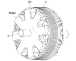
- FIG. 3 is a perspective view of a rotor according to Embodiment 1.
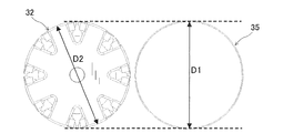
- FIG. FIG. 3 is a perspective view of a state where a cylindrical member of the rotor according to the first embodiment is removed. It is the front view seen from the axial direction of the state which removed the cylindrical member of the rotor which concerns on Embodiment 1.
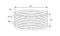
- FIG. It is a perspective view of the steady state of the cylindrical member which concerns on Embodiment 1.
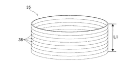
- FIG. is a perspective view which shows a state when the cylindrical member which concerns on Embodiment 1 is mounted
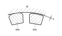
- FIG. 1 It is explanatory drawing which shows the relationship between the field core in Embodiment 1, and the dimension of a cylindrical member. It is explanatory drawing which shows the relationship between the field core in the modification 1, and the dimension of a cylindrical member. It is explanatory drawing which shows the state of the cylindrical member with which the outer periphery of the claw-shaped magnetic pole part was mounted
- FIG. It is a characteristic view which shows the relationship between the tempering temperature after performing hardening about steel with a carbon amount of 0.4%, and a yield point.
- FIG. 5 is a characteristic diagram showing a relationship between a tempering temperature after quenching and a breaking stress when a bar is treated as a beam and a breaking force is applied perpendicular to the longitudinal direction of the beam.
- 6 is a perspective view of a rotor according to Embodiment 2.
- FIG. It is a perspective view of the steady state of the cylindrical member which concerns on Embodiment 2.
- FIG. It is a perspective view which shows a state when the cylindrical member which concerns on Embodiment 2 is mounted
- 10 is a perspective view of a rotor according to Modification 3.
- Embodiment 1 The rotor of the rotating electrical machine according to the first embodiment will be described with reference to FIGS.
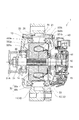
- the rotor according to the first embodiment is mounted on, for example, a rotating electrical machine used as the vehicle alternator 1.
- a rotating electrical machine used as the vehicle alternator 1 As shown in FIGS. 1 and 2, the housing 10, the stator 20, and the rotor 30 are mounted. , Field winding feeding mechanism, rectifier 45 and the like.
- the housing 10 includes a bottomed cylindrical front housing 11 and a rear housing 12 each having an open end.
- the front housing 11 and the rear housing 12 are fastened by bolts 13 in a state where the openings are joined to each other.
- the stator 20 is an armature including an annular stator core 21 having a plurality of slots and teeth (not shown) arranged in the circumferential direction, and a three-phase phase winding wound around the slots of the stator core 21. And winding 25.
- the stator 20 is fixed to the inner peripheral surfaces of the peripheral walls of the front housing 11 and the rear housing 12 while being sandwiched in the axial direction.
- the rotor 30 is disposed on the radially inner side of the stator 20, and is provided so as to be able to rotate integrally with a rotating shaft 31 that is rotatably supported by the housing 10 via a pair of bearings 14, 14.
- the rotor 30 is a Landel type rotor having a field core 32 composed of a pair of pole cores 32 a and 32 b and a field winding 33.
- the rotor 30 is rotationally driven by an engine (not shown) mounted on the vehicle via a pulley 31A fixed to the front end portion of the rotating shaft 31.
- the field winding power supply mechanism is a device for supplying power to the field winding 33, and includes a pair of brushes 41, a pair of slip rings 42, a regulator 43, and the like.
- the rotor 30 rotates in a predetermined direction together with the rotating shaft 31.
- the first and second claw-shaped magnetic pole portions of the first and second pole cores 32a and 32b. 323a and 323b are excited.
- NS magnetic poles are alternately formed along the rotational circumferential direction of the rotor 30.
- a rotating magnetic field is applied to the armature winding 25 of the stator 20, thereby generating an alternating electromotive force in the armature winding 25.
- the alternating electromotive force generated in the armature winding 25 is rectified into a direct current through the rectifier 45 and then supplied to a battery (not shown).
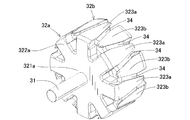
- the rotor 30 according to the first embodiment includes a rotary shaft 31 that is rotatably supported by the housing 10 via a pair of bearings 14 and 14, and an outer periphery of the rotary shaft 31.
- a field core 32 composed of a pair of pole cores 32a and 32b fitted and fixed to each other; a field winding 33 wound around a boss 321 (321a and 321b) of the field core 32; A plurality of permanent magnets 34 disposed between the claw-shaped magnetic pole portions 323 (323a, 323b) adjacent in the circumferential direction and a cylindrical member disposed so as to cover the outer periphery of the claw-shaped magnetic pole portion 323 of the field core 32 35.
- the rotor 30 is rotatably provided on the inner circumferential side of the stator 20 so as to face the radial direction.
- the field core 32 includes a first pole core 32a fixed to the front side (left side in FIG. 1) of the rotary shaft 31 and the rear side (right side in FIG. 1) of the rotary shaft 31.
- the second pole core 32b is fixed.
- the first pole core 32a includes a cylindrical first boss portion 321a, a first disk portion 322a, and a first claw-shaped magnetic pole portion 323a.
- the first boss portion 321 a causes the field magnetic flux to flow in the axial direction on the radially inner side of the field winding 33.
- the first disk portion 322a projects radially outward at a predetermined pitch in the circumferential direction from the axial front end portion of the first boss portion 321a to flow field magnetic flux in the radial direction.
- the first claw-shaped magnetic pole portion 323a protrudes in the axial direction from the outer peripheral end portion of each first disk portion 322a to the outer peripheral side of the first boss portion 321a so as to surround the field winding 33, and the stator core 21 and the magnetic flux Give and receive.
- the second pole core 32b has the same shape as the first pole core 32a, and includes a second boss portion 321b, a second disk portion 322b, and a second claw-shaped magnetic pole portion 323b.
- the first and second pole cores 32a and 32b are made of a soft magnetic material.
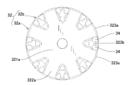
- the first pole core 32a and the second pole core 32b are formed so that the first claw-shaped magnetic pole portions 323a and the second claw-shaped magnetic pole portions 323b face each other alternately so that the axial rear end surface of the first pole core 32a and the second pole core 32b It is assembled in a state in which the front end surface in the axial direction is in contact.
- the first claw-shaped magnetic pole portions 323a of the first pole core 32a and the second claw-shaped magnetic pole portions 323b of the second pole core 32b are alternately arranged in the circumferential direction.
- Each of the first and second pole cores 32a and 32b has eight claw-shaped magnetic pole portions 323.
- a 16-pole (N pole: 8, S pole: 8) Landell rotor core is formed. ing.
- the field winding 33 is wound around the outer peripheral surfaces of the first and second boss portions 321a and 321b while being electrically insulated from the field core 32, and the first and second claw-shaped magnetic pole portions 323a. , 323b.
- the field winding 33 generates a magnetomotive force in the boss portion 321 when a field current If is supplied from a field current control circuit (not shown).
- a field current control circuit not shown.
- magnetic poles having different polarities are formed on the first claw-shaped magnetic pole portion 323a and the second claw-shaped magnetic pole portion 323b of the first and second pole cores 32a and 32b, respectively.
- the first claw-shaped magnetic pole part 323a is magnetized to the S pole
- the second claw-shaped magnetic pole part 323b is magnetized to the N pole.
- the magnetic flux generated in the boss part 321 of the field core 32 by the field winding 33 flows from the first boss part 321a of the first pole core 32a to the first disk part 322a and the first claw-shaped magnetic pole part 323a, for example.
- the first claw-shaped magnetic pole portion 323a flows through the stator core 21 to the second claw-shaped magnetic pole portion 323b of the second pole core 32b, and the second claw-shaped magnetic pole portion 323b, the second disk portion 322b, A magnetic circuit that returns to the first boss portion 321a via the boss portion 321b is formed.
- This magnetic circuit is a magnetic circuit that generates a counter electromotive force of the rotor 30.
- each gap extending in a direction inclined from the axial direction is formed between the first claw-shaped magnetic pole portions 323a and the second claw-shaped magnetic pole portions 323b that are alternately arranged in the circumferential direction.
- One permanent magnet 34 is arranged in each gap.
- Each permanent magnet 34 has a rectangular parallelepiped outer shape, and an easy magnetization axis is directed in the circumferential direction.
- Each permanent magnet 34 has first and second claw-shaped magnetic poles in a state where end surfaces (flux inflow / outflow surfaces) on both sides in the circumferential direction are in contact with the circumferential side surfaces of the first and second claw-shaped magnetic pole portions 323a and 323b, respectively. It is hold
- the permanent magnets 34 are arranged so that the polarities thereof coincide with the polarities alternately appearing in the first and second claw-shaped magnetic pole portions 323a and 323b by the excitation of the field winding 33.
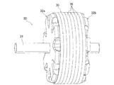
- the cylindrical member 35 is formed in a cylindrical shape by a plurality of ring-shaped steel plates (soft magnetic bodies) 36 stacked in the axial direction, and the field core 32. Are arranged so as to be coaxial with the field core 32 so as to cover the outer peripheral surface of the claw-shaped magnetic pole portion 323.
- the cylindrical member 35 has the same axial width as the axial length of the claw-shaped magnetic pole portion 323. Therefore, the cylindrical member 35 is formed in a size that covers the entire outer peripheral surface of the claw-shaped magnetic pole portion 323.
- the cylindrical member 35 has an inner diameter D ⁇ b> 1 in a steady state that is smaller than an outer diameter D ⁇ b> 2 of the claw-shaped magnetic pole part 323.
- the steady state in the first embodiment means a state in which no external force is applied before the cylindrical member 35 is attached to the outer periphery of the field core 32.
- the cylindrical member 35 is fitted on the outer peripheral surface of the claw-shaped magnetic pole portion 323 by press fitting, and is fixed in a state where a predetermined pressure is applied to the outer peripheral surface of the claw-shaped magnetic pole portion 323. As a result, as shown in FIG.
- the claw-shaped magnetic pole portion 323 is deformed by the centrifugal force generated when the rotor 30 rotates as shown in FIG. Further, since the claw-shaped magnetic pole part 323 extends from the base of the claw-shaped magnetic pole part 323, chatter vibration of a similar mode is generated by vibration, and the total force of the centrifugal force and the vibration is generated. Increase stress. In the case of the first embodiment, since the inner diameter surface of the cylindrical member 35 suppresses the claw-shaped magnetic pole portion 323 like a spring, a vibration damper effect is obtained.
- the cylindrical member 35 is formed with a distorted portion 35A that protrudes toward the inner diameter side, the pressing force of the distorted portion 35A is applied to the outer peripheral surface of the claw-shaped magnetic pole portion 323. Therefore, a better damper effect can be obtained.
- the cylindrical member 35 of Embodiment 1 has an axial length L1 that is smaller than an axial length L2 in a steady state when mounted on the outer periphery of the claw-shaped magnetic pole portion 323. Yes. That is, when the cylindrical member 35 is mounted on the outer periphery of the claw-shaped magnetic pole portion 323, it is desirable that the steel plates 36 adjacent in the axial direction are in close contact with each other in order to obtain a magnetically dense structure. Further, the cylindrical member 35 has a gap G ⁇ b> 1 between at least a part of the steel plates 36 adjacent in the axial direction in order to suppress the axial vibration of the cylindrical member 35.
- the steel plate 36 constituting the cylindrical member 35 is composed of a ring-shaped magnetic body and an electrically insulating layer that covers both the front and back surfaces of the magnetic body. Therefore, the cylindrical member 35 formed by laminating a plurality of steel plates 36 has a structure in which magnetic bodies and electrical insulating layers are alternately laminated in the axial direction. Thereby, the eddy current loss in the cylindrical member 35 can be reduced.
- the magnetic body is made of a magnetic material having a carbon content of 0.4 to 1.05%.
- iron containing carbon is hardened by quenching or processing, and then forms a martensite structure through a tempering process, and becomes high strength. This is widely known in common sense. It is effective in the present disclosure to obtain an ideal aspect as a structural material by using this structure. That is, in the present disclosure, it can be said that electromagnetic soft iron that cannot sufficiently form a martensite structure is not a suitable material.
- FIG. 11 is a characteristic diagram showing the relationship between the tempering temperature and the yield point after quenching for steel with a carbon content of 0.4%. It can be confirmed from FIG. 11 that the stress is increased at a temperature of 200 ° C. when the carbon content is 0.4%. Therefore, it can be said that the effect is confirmed if the carbon content is 0.4%.
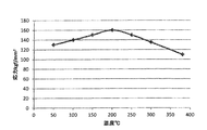
- FIG. 12 is a characteristic diagram showing the relationship between the tempering temperature after quenching and the breaking stress when a bar is treated as a beam and a breaking force is applied perpendicular to the longitudinal direction of the beam.
- This breaking stress is a method of applying a stress close to whether or not the tubular member 35 breaks when receiving the force of the claw-shaped magnetic pole portion 323 and the permanent magnet 34.
- a high carbon steel having a carbon content different from the S10C class low carbon steel generally used as a magnetic material has the most excellent breaking stress value at about 200 ° C.
- a temperature range of about 80 to 200 ° C. in the vicinity of the installation site of the rotating electrical machine according to Embodiment 1 is suitable as a tempering temperature if the carbon content is in the range of 1.35% or less. ing. Further, when the carbon content is in the range of 1.05% or less, a temperature range of about 80 to 200 ° C. near the installation site of the rotating electrical machine according to Embodiment 1 is more suitable as the tempering temperature. For this reason, members within the above carbon amount range are partially heated by heat generated by iron loss or the like of high-energy bodies such as centrifugal force, magnets, and magnetic pole surface of the rotor, and tempered during operation. In this way, it is spontaneously brought into an ideal state.
- the ferrous material containing 0.4% to 1.35% carbon is suitable for the steel plate 36 of the cylindrical member 35, and the ferrous material containing 0.4% to 1.05% carbon is used. It can be said that this is more suitable for the steel plate 36 of the cylindrical member 35.
- the JIS symbols are classified into SK, SUP, SWRH, SWRS, etc., and those called carbon tool steel, hard steel wire, piano wire, and martensitic stainless steel are respectively used for the cylindrical member 35. Suitable for steel plate 36.
- the cylindrical member 35 is configured by the plurality of steel plates 36 stacked in the axial direction, and the inner diameter D1 in the steady state is the claw-shaped magnetic pole portion 323. It is smaller than the outer diameter D2. Therefore, when the cylindrical member 35 is mounted on the outer periphery of the claw-shaped magnetic pole portion 323, the inner peripheral surface of the cylindrical member 35 is in close contact with the outer peripheral surface of the claw-shaped magnetic pole portion 323, and the claw-shaped magnetic pole portion 323 is pressed. A gap (air gap) is not formed between the portion 323 and the cylindrical member 35. Thereby, it is possible to improve the torque by reducing the magnetic resistance and to avoid the strength reduction due to the vibration of the claw-shaped magnetic pole portion 323.
- the cylindrical member 35 has an axial length L1 that is smaller than the axial length L2 in the steady state when mounted on the outer periphery of the claw-shaped magnetic pole portion 323, and is at least partially adjacent in the axial direction.
- a gap G ⁇ b> 1 is provided between the steel plates 36. According to this configuration, when the cylindrical member 35 is mounted, the cylindrical member 35 can have a magnetically dense structure, and vibration in the axial direction of the cylindrical member 35 can be suppressed.
- the steel plate 36 constituting the cylindrical member 35 is formed of a magnetic material having a carbon content of 0.4 to 1.05%. Therefore, in a rotating electrical machine that is used in an environment where the temperature changes greatly between when the vehicle is operated and when the operation is stopped, material deterioration during the operation of the vehicle and low temperature tempering when the vehicle is stopped are repeated. Thereby, the material composition of the steel plate 36 is automatically restored. Therefore, the strength of the product is ensured at a high level without heat deterioration.
- FIGS. 1 A rotor 30 according to the second embodiment will be described with reference to FIGS.
- the basic configuration of the rotor 30 according to the second embodiment is the same as that of the first embodiment, but only the configuration of the cylindrical member 37 is different from the first embodiment.
- different points and important points will be described.
- symbol is used and detailed description is abbreviate
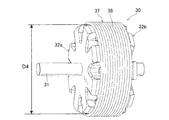
- the cylindrical member 37 of Embodiment 2 is configured by a steel wire 38 that is spirally wound and laminated in the axial direction.
- the cylindrical member 37 has an inner diameter D3 (FIG. 14) in a steady state smaller than an outer diameter D4 (FIG. 13) of the claw-shaped magnetic pole portion 323.
- the steady state in the second embodiment means a state in which no external force is applied before the cylindrical member 37 is mounted on the outer periphery of the field core 32.
- the cylindrical member 37 is fitted into the outer peripheral surface of the claw-shaped magnetic pole portion 323 by press fitting, and is fixed in a state where a predetermined pressure is applied to the outer peripheral surface of the claw-shaped magnetic pole portion 323.
- the cylindrical member 37 has an axial length L3 when it is mounted on the outer periphery of the claw-shaped magnetic pole portion 323 so that the natural length of the cylindrical member 37 (the cylindrical member 37 has a field
- the axial length of the cylindrical member 37 in a state where no external force is applied before being attached to the outer periphery of the core 32 is made smaller.
- the cylindrical member 37 has a gap G ⁇ b> 2 between at least a part of the steel wires 38 adjacent to the cylindrical member 37 in the axial direction in order to suppress vibration in the axial direction of the cylindrical member 37. ing.
- the steel wire 38 which comprises the cylindrical member 37 consists of a steel wire with a circular cross section and an electrically insulating layer covering the outer peripheral surface of the steel wire.
- the steel wire is formed of a magnetic material having a carbon content of preferably 0.4 to 1.35%, more preferably 0.4 to 1.05%, as in the first embodiment.
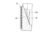
- the cylindrical member 37 is adjacent to the axial direction by a resin adhesive 39 applied between the outer peripheral surface of the claw-shaped magnetic pole portion 323 and the inner peripheral surface of the cylindrical member 37.
- Steel wires 38 are connected and fixed on the inner peripheral side.
- the cylindrical member 37 is configured by the steel wire 38 that is spirally wound and stacked in the axial direction, and the inner diameter D3 in the steady state has a claw.
- the magnetic pole portion 323 is smaller than the outer diameter D4. Therefore, no gap (air gap) is formed between the claw-shaped magnetic pole part 323 and the cylindrical member 37. Therefore, according to the rotor 30 of the second embodiment, the same operations and effects as those of the first embodiment can be realized, such as an improvement in torque due to a reduction in magnetic resistance and avoidance of a decrease in strength due to vibration of the claw-shaped magnetic pole portion 323. Play.
- the tubular member 37 has the steel wires 38 adjacent to each other in the axial direction coupled and fixed on the inner peripheral side by the resin adhesive 39. Therefore, it is possible to prevent the occurrence of a problem that the cylindrical member 37 tends to fall apart when the self-weight or impact load is input or when the composition changes due to tempering.
- the tubular member 37 is formed by connecting and fixing the steel wires 38 adjacent in the axial direction on the inner peripheral side.
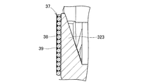
- the steel wires 38 adjacent to each other in the axial direction may be connected and fixed on the outer peripheral side with a resin adhesive 39 or the like applied to the outer peripheral surface of 37.
- the steel plates 36 adjacent to each other in the axial direction are also connected and fixed to the cylindrical member 35 of the first embodiment on the inner peripheral side or the outer peripheral side with a resin adhesive or the like as in the second embodiment. May be.
- the steel wire 38 constituting the cylindrical member 37 has a circular cross section, but instead of this, a steel wire 38A having a rectangular cross section as in Modification 3 shown in FIG. May be adopted.
- the rotor 30 according to the present invention is applied to the vehicle alternator 1 .
- an electric motor as a rotating electric machine mounted on the vehicle, and further, a generator and an electric motor are provided.
- the present invention can also be applied to rotating electrical machines that can be used selectively.
- a rotor (30) of a rotating electrical machine comprising a cylindrical member (35) arranged to cover the outer periphery of the claw-shaped magnetic pole part,
- the cylindrical member is composed of a plurality of steel plates (36) stacked in the axial direction, and an inner diameter (D1) in a steady state is smaller than an outer diameter (D2) of the claw
- the cylindrical member is composed of a plurality of steel plates stacked in the axial direction, and the inner diameter in a steady state is smaller than the outer diameter of the claw-shaped magnetic pole portion. Therefore, when the cylindrical member is mounted on the outer periphery of the claw-shaped magnetic pole portion, the inner peripheral surface of the cylindrical member is in close contact with the outer peripheral surface of the claw-shaped magnetic pole portion, and the claw-shaped magnetic pole portion and the cylindrical shape No gap (air gap) is formed between the members. Thereby, the improvement of the torque by reduction of magnetic resistance and the avoidance of the strength reduction by the vibration of the claw-shaped magnetic pole part can be realized.
- the cylindrical member has an axial length (L1) when mounted on an outer periphery of the claw-shaped magnetic pole portion, which is longer than an axial length (L2) in a steady state.
- a gap (G1) is provided between at least some of the steel plates that are made smaller and are axially adjacent.
- the cylindrical member can have a magnetically dense structure when the cylindrical member is mounted.
- the axial vibration of the cylindrical member can be suppressed. Even if the gap between the steel plates is a minute gap between the insulating films provided on the surface of the steel plate, a certain degree of vibration suppressing effect can be obtained.
- the cylindrical member when mounting the cylindrical member on the outer periphery of the claw-shaped magnetic pole part, without providing a member for fixing the cylindrical member, by increasing the friction coefficient of the contact surface of the cylindrical member and the claw-shaped magnetic pole part, The position in the axial direction may be fixed. At this time, it is preferable to use irregularities due to cutting marks formed on the outer peripheral surface of the claw-shaped magnetic pole portion, which usually becomes an air gap, because irregularities can be freely formed.
- a rotor (30) of a rotating electrical machine comprising a cylindrical member (37) arranged to cover the outer periphery of the claw-shaped magnetic pole part,
- the cylindrical member is composed of steel wires (38, 38A) which are spirally wound and laminated in the axial direction, and the inner diameter (D3) in a steady state is larger than the outer diameter (D4) of the claw-shaped magnetic
- the cylindrical member is formed of a steel wire that is spirally wound and laminated in the axial direction, and the inner diameter in a steady state is smaller than the outer diameter of the claw-shaped magnetic pole portion. Therefore, when the cylindrical member is mounted on the outer periphery of the claw-shaped magnetic pole portion, the inner peripheral surface of the cylindrical member is in close contact with the outer peripheral surface of the claw-shaped magnetic pole portion, and the claw-shaped magnetic pole portion and the cylindrical shape No gap (air gap) is formed between the members. Thereby, the improvement of the torque by reduction of magnetic resistance and the avoidance of the strength reduction by the vibration of the claw-shaped magnetic pole part can be realized. Further, when mounting the cylindrical member, the diameter of the cylindrical member can be expanded and mounted on the outer periphery of the claw-shaped magnetic pole portion, so that the mounting operation of the cylindrical member is facilitated.
- the cylindrical member has an axial length (L3) when mounted on an outer periphery of the claw-shaped magnetic pole portion, and a natural length (L4) of the cylindrical member. And a gap (G2) between at least some of the steel wires adjacent in the axial direction. According to this structure, the vibration of the cylindrical member in the axial direction can be suppressed. In addition, about the mounting
- the magnetic material constituting the cylindrical member has a carbon content of 0.4 to 1.05%.
- a rotating electrical machine such as a motor equipped with the rotor of the present disclosure is used in an environment where the temperature changes from minus to 100 ° C. or more. Therefore, by adopting the present disclosure, the surface of the claw-shaped magnetic pole part that is a heat source within the operating temperature range, the permanent magnet of the adjacent heat source, and the cylindrical member that receives heat from the stator are low-temperature baked. The effect of reversion is exhibited, and the composition can be automatically repaired.
- Distortion due to centrifugal force and stress due to temperature change is heated by large iron loss and copper loss due to a large current at the start of idle stop, and the cylindrical member is exposed to a particularly high temperature.
- the cylindrical member of the present invention having a low heat capacity and receiving heat generated by a heat source designed with a limit of 100 to 200 ° C. is equivalent to that.
- the cylindrical member is formed by connecting and fixing the steels adjacent in the axial direction on the inner peripheral side. According to this configuration, it is possible to prevent the occurrence of a problem that the cylindrical member tends to fall apart when the weight or impact load is input or when the composition changes due to tempering.
- the axial dimension may not be determined, especially when the material selection is made of a material having a carbon content of 0.6% or more, which is tempered at a low temperature. There is sex.
- the carbon content of the materials shown in Patent Documents 1 and 2 can be assumed to be 0.1% or less in consideration of the content suggestion of electromagnetic properties.
- a fixing means welding, an adhesive agent, etc. are employable, for example.
- the cylindrical member is configured such that the steels adjacent in the axial direction are connected and fixed on the outer peripheral side. According to this structure, generation
- a fixing means a varnish, an adhesive agent, etc. are employable. Alternatively, a material having a self-bonding function that is bonded by heating may be used.
Abstract
A rotor (30) for a rotating electrical machine (1) comprising: a field core (32) having a boss (321), a plurality of disks (322), and a plurality of hook-shaped magnetic poles (323); a field winding (33) wound on the outer circumferential side of the boss (321) and generating magnetomotive force as a result of having current supplied thereto; and a cylindrical member (35) arranged so as to cover the outer circumference of the hook-shaped magnetic poles. The cylindrical member (35) comprises a plurality of metal plates (36) laminated in the axial direction and has an inner diameter (D1) in a steady state that is smaller than the outer diameter (D2) of the hook-shaped magnetic poles (323).
Description
本出願は、2016年6月3日に出願された特許出願番号2016-112287号に基づくものであって、その優先権の利益を主張するものであり、その特許出願のすべての内容が、参照により本明細書に組み入れられる。
This application is based on patent application No. 2016-112287 filed on June 3, 2016, and claims the benefit of its priority. Is incorporated herein by reference.
本開示は、例えば自動車やトラック等に搭載されて電動機や発電機として使用される回転電機の回転子に関する。
The present disclosure relates to a rotor of a rotating electrical machine that is mounted on, for example, an automobile or a truck and used as an electric motor or a generator.
従来の回転電機として、固定子巻線が巻装された固定子と、該固定子と電磁ギャップを隔てて径方向に対向して回転可能に配置された回転子とを備えたものが知られている。回転電機の回転子として、複数の爪状磁極部を有する界磁コアと、界磁巻線と、を備えたランデル型回転子が知られている。前記界磁コアには、回転軸に固定される円筒状のボス部と、該ボス部の外周側に配置されて周方向交互に異なる極性の磁極とが形成される。前記界磁巻線は、前記ボス部の外周側に巻装されて通電により起磁力を発生する。
As a conventional rotating electric machine, there has been known one provided with a stator around which a stator winding is wound, and a rotor arranged to be rotatably opposed to the stator in a radial direction across an electromagnetic gap. ing. As a rotor of a rotating electrical machine, a Landell type rotor including a field core having a plurality of claw-shaped magnetic pole portions and a field winding is known. The field core is formed with a cylindrical boss portion fixed to the rotating shaft and magnetic poles arranged on the outer peripheral side of the boss portion and having different polarities alternately in the circumferential direction. The field winding is wound around the outer peripheral side of the boss portion and generates a magnetomotive force when energized.
特許文献1には、軸方向に複数枚の軟磁性板が積層された積層体からなり、界磁コアの爪状磁極部の外周側に配置された筒状の磁極筒部(筒状部材)が開示されている。この筒状部材は、外径側表面に、爪状磁極部の輪郭形状に対応した凸部と、隣り合う爪状磁極部の間の空隙に対応した凹部とを有する。筒状部材の凸部と凹部とはスロープ状に接続されている。これにより、特許文献1の筒状部材によれば、回転子が回転した際に、固定子に作用する磁束の変動を緩和して磁気騒音を低減することが可能とされている。
In Patent Document 1, a cylindrical magnetic pole cylinder portion (cylindrical member) is formed of a laminated body in which a plurality of soft magnetic plates are laminated in the axial direction, and is arranged on the outer peripheral side of the claw-shaped magnetic pole part of the field core. Is disclosed. This cylindrical member has a convex portion corresponding to the contour shape of the claw-shaped magnetic pole portion and a concave portion corresponding to the gap between adjacent claw-shaped magnetic pole portions on the outer diameter side surface. The convex portion and the concave portion of the cylindrical member are connected in a slope shape. Thereby, according to the cylindrical member of patent document 1, when a rotor rotates, it is made possible to relieve | moderate the fluctuation | variation of the magnetic flux which acts on a stator, and to reduce a magnetic noise.
また、特許文献2には、丸孔やスリットを有する帯板状の軟磁性長尺板を、螺旋状に巻き重ねて軸方向に積層することによりロータコアを形成する技術が記載されている。
Further, Patent Document 2 describes a technique for forming a rotor core by winding a strip-shaped soft magnetic long plate having round holes and slits in a spiral manner and laminating them in the axial direction.
特許文献1に記載された筒状部材のように、界磁コアの爪状磁極部の外周側に配置される部材は、真円度が十分でない場合には、爪状磁極部の外周面に対して浮き(隙間)がある箇所と、浮きが無い箇所が存在する。そのため、耐震強度的に強固な部分とそうでない部分とが存在することとなる。特に、振動による爪状磁極部のビビリ音は、ランデル型モータの性能悪化要因として取り上げられることも多い。特許文献1の場合には、往々にしてこのような状況が起きやすい。この状況では、浮きのある箇所で、エアギャップによる磁気抵抗が強くなり、磁力低下も併発している。
Like the cylindrical member described in Patent Document 1, a member disposed on the outer peripheral side of the claw-shaped magnetic pole portion of the field core is formed on the outer peripheral surface of the claw-shaped magnetic pole portion when the roundness is not sufficient. On the other hand, there are places where there is a float (gap) and places where there is no float. Therefore, there will be a portion that is strong in seismic strength and a portion that is not. In particular, the chattering noise of the claw-shaped magnetic pole portion due to vibration is often taken up as a factor that deteriorates the performance of the Landell motor. In the case of Patent Document 1, such a situation often occurs. In this situation, the magnetic resistance due to the air gap is increased and the magnetic force is reduced at the floating portion.
また、特許文献2に記載の技術では、丸孔やスリットを有する帯板状の軟磁性長尺板を、螺旋状に巻き重ねることによって、円筒形状のロータコアが作製される。このような場合には、潰した(塑性変形させた)部分に応力集中係数の増加が起こり、強度設計上良くないことは自明である。また、潰した部分に隙間が形成されるため、磁気回路の構成部品としての能力が低下することになる。その結果、磁性体が粗になり、磁気的性能の低下が起こることも自明である。
In the technique described in Patent Document 2, a cylindrical rotor core is manufactured by spirally winding a strip-shaped soft magnetic long plate having round holes and slits. In such a case, it is obvious that the stress concentration coefficient increases in the crushed (plastically deformed) portion, which is not good in strength design. Further, since a gap is formed in the crushed portion, the ability as a component of the magnetic circuit is reduced. As a result, it is obvious that the magnetic material becomes rough and the magnetic performance is degraded.
本開示は、爪状磁極部の外周側に配置される筒状部材と爪状磁極部との間の隙間を無くすことにより、磁気抵抗の低減によるトルクの向上と、爪状磁極部の振動による強度低下の回避を実現できる回転電機の固定子を提供することを解決すべき課題とする。
The present disclosure eliminates the gap between the cylindrical member disposed on the outer peripheral side of the claw-shaped magnetic pole part and the claw-shaped magnetic pole part, thereby improving torque by reducing the magnetic resistance and by vibrating the claw-shaped magnetic pole part. It is an object to be solved to provide a stator of a rotating electrical machine that can realize a reduction in strength. *
本開示の第一の態様では、
筒状のボス部、前記ボス部の軸方向端部から周方向所定ピッチで径方向外側に突出する複数のディスク部、及び、各前記ディスク部の外周端部から前記ボス部の外周側へ軸方向に突出し、周方向交互に異なる極性に磁化される複数の爪状磁極部を有する界磁コアと、
前記ボス部の外周側に巻装されて通電により起磁力を発生する界磁巻線と、
前記爪状磁極部の外周を覆うように配置された筒状部材と、を備えた回転電機の回転子において、
前記筒状部材は、軸方向に積層された複数の鋼の板により構成され、定常状態における内径が前記爪状磁極部の外径よりも小さくされている。 In a first aspect of the present disclosure,
A cylindrical boss part, a plurality of disk parts projecting radially outward from the axial end part of the boss part at a predetermined circumferential direction pitch, and an axis from the outer peripheral end part of each disk part to the outer peripheral side of the boss part A field core having a plurality of claw-shaped magnetic pole portions that protrude in the direction and are magnetized in different polarities in the circumferential direction;
A field winding wound around the outer periphery of the boss and generating a magnetomotive force by energization;
In a rotor of a rotating electrical machine comprising a cylindrical member arranged to cover the outer periphery of the claw-shaped magnetic pole part,
The cylindrical member is composed of a plurality of steel plates laminated in the axial direction, and the inner diameter in a steady state is smaller than the outer diameter of the claw-shaped magnetic pole part.
この構成によれば、筒状部材は、軸方向に積層された複数の鋼の板により構成され、定常状態における内径が爪状磁極部の外径よりも小さくされている。そのため、爪状磁極部の外周に筒状部材を装着した際に、爪状磁極部の外周面に筒状部材の内周面が押圧しつつ密着した状態になり、爪状磁極部と筒状部材との間に隙間(エアギャップ)が形成されない。これにより、磁気抵抗の低減によるトルクの向上と、爪状磁極部の振動による強度低下の回避を実現できる。
According to this configuration, the cylindrical member is composed of a plurality of steel plates stacked in the axial direction, and the inner diameter in a steady state is smaller than the outer diameter of the claw-shaped magnetic pole portion. Therefore, when the cylindrical member is mounted on the outer periphery of the claw-shaped magnetic pole portion, the inner peripheral surface of the cylindrical member is in close contact with the outer peripheral surface of the claw-shaped magnetic pole portion, and the claw-shaped magnetic pole portion and the cylindrical shape No gap (air gap) is formed between the members. Thereby, the improvement of the torque by reduction of magnetic resistance and the avoidance of the strength reduction by the vibration of the claw-shaped magnetic pole part can be realized.
以下、本発明に係る回転電機の回転子の実施形態について図面を参照して具体的に説明する。
Hereinafter, an embodiment of a rotor of a rotating electrical machine according to the present invention will be specifically described with reference to the drawings.
〔実施形態1〕
実施形態1に係る回転電機の回転子について図1~図12を参照して説明する。実施形態1の回転子は、例えば車両用交流発電機1として使用される回転電機に搭載されるものであって、図1および図2に示すように、ハウジング10、固定子20、回転子30、界磁巻線給電機構、整流器45等を含む。 Embodiment 1
The rotor of the rotating electrical machine according to the first embodiment will be described with reference to FIGS. The rotor according to the first embodiment is mounted on, for example, a rotating electrical machine used as the vehicle alternator 1. As shown in FIGS. 1 and 2, thehousing 10, the stator 20, and the rotor 30 are mounted. , Field winding feeding mechanism, rectifier 45 and the like.
実施形態1に係る回転電機の回転子について図1~図12を参照して説明する。実施形態1の回転子は、例えば車両用交流発電機1として使用される回転電機に搭載されるものであって、図1および図2に示すように、ハウジング10、固定子20、回転子30、界磁巻線給電機構、整流器45等を含む。 Embodiment 1
The rotor of the rotating electrical machine according to the first embodiment will be described with reference to FIGS. The rotor according to the first embodiment is mounted on, for example, a rotating electrical machine used as the vehicle alternator 1. As shown in FIGS. 1 and 2, the
ハウジング10は、それぞれ一端が開口した有底円筒状のフロントハウジング11とリアハウジング12とからなる。フロントハウジング11とリアハウジング12は、開口部同士が接合された状態でボルト13により締結されている。固定子20は、周方向に配列された図示しない複数のスロット及びティースを有する円環状の固定子コア21と、固定子コア21のスロットに巻装された三相の相巻線よりなる電機子巻線25とを有する。この固定子20は、フロントハウジング11とリアハウジング12の周壁内周面に、軸方向に挟持された状態で固定されている。
The housing 10 includes a bottomed cylindrical front housing 11 and a rear housing 12 each having an open end. The front housing 11 and the rear housing 12 are fastened by bolts 13 in a state where the openings are joined to each other. The stator 20 is an armature including an annular stator core 21 having a plurality of slots and teeth (not shown) arranged in the circumferential direction, and a three-phase phase winding wound around the slots of the stator core 21. And winding 25. The stator 20 is fixed to the inner peripheral surfaces of the peripheral walls of the front housing 11 and the rear housing 12 while being sandwiched in the axial direction.
回転子30は、固定子20の径方向内側に配置されており、ハウジング10に一対の軸受け14,14を介して回転自在に支持された回転軸31に一体回転可能に設けられている。この回転子30は、一対のポールコア32a,32bよりなる界磁コア32と界磁巻線33とを有するランデル型回転子である。回転子30は、回転軸31の前端部に固定されたプーリ31Aを介して、車両に搭載された図示しないエンジンによって回転駆動される。界磁巻線給電機構は、界磁巻線33に給電するための装置であり、一対のブラシ41、一対のスリップリング42及びレギュレータ43等を有する。
The rotor 30 is disposed on the radially inner side of the stator 20, and is provided so as to be able to rotate integrally with a rotating shaft 31 that is rotatably supported by the housing 10 via a pair of bearings 14, 14. The rotor 30 is a Landel type rotor having a field core 32 composed of a pair of pole cores 32 a and 32 b and a field winding 33. The rotor 30 is rotationally driven by an engine (not shown) mounted on the vehicle via a pulley 31A fixed to the front end portion of the rotating shaft 31. The field winding power supply mechanism is a device for supplying power to the field winding 33, and includes a pair of brushes 41, a pair of slip rings 42, a regulator 43, and the like.
以上の構成を有する車両用交流発電機1は、図示しないベルト等を介してプーリ31Aにエンジンからの回転力が伝えられると、回転子30が回転軸31と共に所定方向に回転する。この状態で、ブラシ41からスリップリング42を介して回転子30の界磁巻線33に励磁電圧を印加することにより、第1及び第2ポールコア32a,32bの第1及び第2爪状磁極部323a,323bが励磁される。その結果、回転子30の回転周方向に沿って交互にNS磁極が形成される。これにより、固定子20の電機子巻線25に回転磁界が付与されることで、電機子巻線25に交流の起電力を発生させる。電機子巻線25で発生した交流の起電力は、整流器45を通って直流電流に整流された後、図示しないバッテリに供給される。
In the vehicular AC generator 1 having the above configuration, when the rotational force from the engine is transmitted to the pulley 31A via a belt (not shown) or the like, the rotor 30 rotates in a predetermined direction together with the rotating shaft 31. In this state, by applying an excitation voltage from the brush 41 to the field winding 33 of the rotor 30 via the slip ring 42, the first and second claw-shaped magnetic pole portions of the first and second pole cores 32a and 32b. 323a and 323b are excited. As a result, NS magnetic poles are alternately formed along the rotational circumferential direction of the rotor 30. As a result, a rotating magnetic field is applied to the armature winding 25 of the stator 20, thereby generating an alternating electromotive force in the armature winding 25. The alternating electromotive force generated in the armature winding 25 is rectified into a direct current through the rectifier 45 and then supplied to a battery (not shown).
次に、実施形態1の回転子30の特徴構成について図1~図10を参照して詳しく説明する。実施形態1の回転子30は、図1~図4および図10に示すように、ハウジング10に一対の軸受け14,14を介して回転自在に支持される回転軸31と、回転軸31の外周に嵌合固定された一対のポールコア32a,32bよりなる界磁コア32と、界磁コア32のボス部321(321a、321b)に巻装された界磁巻線33と、界磁コア32の周方向に隣接する爪状磁極部323(323a、323b)の間に配置された複数の永久磁石34と、界磁コア32の爪状磁極部323の外周を覆うように配置された筒状部材35と、を有する。この回転子30は、固定子20の内周側に径方向に対向して回転可能に設けられている。
Next, the characteristic configuration of the rotor 30 according to the first embodiment will be described in detail with reference to FIGS. As shown in FIGS. 1 to 4 and 10, the rotor 30 according to the first embodiment includes a rotary shaft 31 that is rotatably supported by the housing 10 via a pair of bearings 14 and 14, and an outer periphery of the rotary shaft 31. A field core 32 composed of a pair of pole cores 32a and 32b fitted and fixed to each other; a field winding 33 wound around a boss 321 (321a and 321b) of the field core 32; A plurality of permanent magnets 34 disposed between the claw-shaped magnetic pole portions 323 (323a, 323b) adjacent in the circumferential direction and a cylindrical member disposed so as to cover the outer periphery of the claw-shaped magnetic pole portion 323 of the field core 32 35. The rotor 30 is rotatably provided on the inner circumferential side of the stator 20 so as to face the radial direction.
界磁コア32は、図1及び図3に示すように、回転軸31の前側(図1の左側)に固定された第1ポールコア32aと、回転軸31の後側(図1の右側)に固定された第2ポールコア32bとにより構成されている。第1ポールコア32aは、円筒状の第1ボス部321aと、第1ディスク部322aと、第1爪状磁極部323aとからなる。第1ボス部321aは、界磁巻線33の径方向内側にて界磁束を軸方向に流す。第1ディスク部322aは、第1ボス部321aの軸方向前端部から周方向の所定ピッチで径方向外側へ突出して界磁束を径方向に流す。第1爪状磁極部323aは、各第1ディスク部322aの外周端部から第1ボス部321aの外周側へ界磁巻線33を囲むように軸方向に突出して固定子コア21と磁束の授受をする。
As shown in FIGS. 1 and 3, the field core 32 includes a first pole core 32a fixed to the front side (left side in FIG. 1) of the rotary shaft 31 and the rear side (right side in FIG. 1) of the rotary shaft 31. The second pole core 32b is fixed. The first pole core 32a includes a cylindrical first boss portion 321a, a first disk portion 322a, and a first claw-shaped magnetic pole portion 323a. The first boss portion 321 a causes the field magnetic flux to flow in the axial direction on the radially inner side of the field winding 33. The first disk portion 322a projects radially outward at a predetermined pitch in the circumferential direction from the axial front end portion of the first boss portion 321a to flow field magnetic flux in the radial direction. The first claw-shaped magnetic pole portion 323a protrudes in the axial direction from the outer peripheral end portion of each first disk portion 322a to the outer peripheral side of the first boss portion 321a so as to surround the field winding 33, and the stator core 21 and the magnetic flux Give and receive.
第2ポールコア32bは、第1ポールコア32aと同一形状を有し、第2ボス部321bと、第2ディスク部322bと、第2爪状磁極部323bとからなる。第1及び第2ポールコア32a,32bは、軟磁性体からなる。
The second pole core 32b has the same shape as the first pole core 32a, and includes a second boss portion 321b, a second disk portion 322b, and a second claw-shaped magnetic pole portion 323b. The first and second pole cores 32a and 32b are made of a soft magnetic material.
第1ポールコア32aと第2ポールコア32bは、第1爪状磁極部323aと第2爪状磁極部323bを互い違いに向かい合わせるようにして、第1ポールコア32aの軸方向後端面と第2ポールコア32bの軸方向前端面とが接触した状態に組み付けられている。これにより、第1ポールコア32aの第1爪状磁極部323aと第2ポールコア32bの第2爪状磁極部323bとが周方向で交互に配置される。第1及び第2ポールコア32a,32bは、それぞれ8個の爪状磁極部323をもち、実施形態1では、16極(N極:8、S極:8)のランデル型回転子コアを形成している。
The first pole core 32a and the second pole core 32b are formed so that the first claw-shaped magnetic pole portions 323a and the second claw-shaped magnetic pole portions 323b face each other alternately so that the axial rear end surface of the first pole core 32a and the second pole core 32b It is assembled in a state in which the front end surface in the axial direction is in contact. Thus, the first claw-shaped magnetic pole portions 323a of the first pole core 32a and the second claw-shaped magnetic pole portions 323b of the second pole core 32b are alternately arranged in the circumferential direction. Each of the first and second pole cores 32a and 32b has eight claw-shaped magnetic pole portions 323. In the first embodiment, a 16-pole (N pole: 8, S pole: 8) Landell rotor core is formed. ing.
界磁巻線33は、第1及び第2ボス部321a,321bの外周面に界磁コア32と電気的に絶縁された状態で巻装されており、第1及び第2爪状磁極部323a,323bに囲まれている。この界磁巻線33は、図示しない界磁電流制御回路から界磁電流Ifが通電されることによってボス部321に起磁力を発生させる。これにより、第1及び第2ポールコア32a,32bの第1爪状磁極部323aと第2爪状磁極部323bにそれぞれ異なる極性の磁極が形成される。実施形態1の場合には、第1爪状磁極部323aがS極に磁化され、第2爪状磁極部323bがN極に磁化される。
The field winding 33 is wound around the outer peripheral surfaces of the first and second boss portions 321a and 321b while being electrically insulated from the field core 32, and the first and second claw-shaped magnetic pole portions 323a. , 323b. The field winding 33 generates a magnetomotive force in the boss portion 321 when a field current If is supplied from a field current control circuit (not shown). As a result, magnetic poles having different polarities are formed on the first claw-shaped magnetic pole portion 323a and the second claw-shaped magnetic pole portion 323b of the first and second pole cores 32a and 32b, respectively. In the case of the first embodiment, the first claw-shaped magnetic pole part 323a is magnetized to the S pole, and the second claw-shaped magnetic pole part 323b is magnetized to the N pole.
この場合、界磁巻線33により界磁コア32のボス部321に発生した磁束は、例えば第1ポールコア32aの第1ボス部321aから第1ディスク部322a、第1爪状磁極部323aに流れた後、第1爪状磁極部323aから固定子コア21を経由して第2ポールコア32bの第2爪状磁極部323bに流れ、第2爪状磁極部323bから第2ディスク部322b、第2ボス部321bを経由して第1ボス部321aに戻る磁気回路を形成する。この磁気回路は、回転子30の逆起電力を生む磁気回路である。
In this case, the magnetic flux generated in the boss part 321 of the field core 32 by the field winding 33 flows from the first boss part 321a of the first pole core 32a to the first disk part 322a and the first claw-shaped magnetic pole part 323a, for example. After that, the first claw-shaped magnetic pole portion 323a flows through the stator core 21 to the second claw-shaped magnetic pole portion 323b of the second pole core 32b, and the second claw-shaped magnetic pole portion 323b, the second disk portion 322b, A magnetic circuit that returns to the first boss portion 321a via the boss portion 321b is formed. This magnetic circuit is a magnetic circuit that generates a counter electromotive force of the rotor 30.
そして、図3に示すように、周方向で交互に配置された第1爪状磁極部323aと第2爪状磁極部323bの間には、軸方向から傾斜した方向に延在する隙間が形成されており、各隙間には永久磁石34が1個ずつ配置されている。各永久磁石34は、直方体形状の外形を有し、磁化容易軸が周方向に向けられる。また、各永久磁石34は、周方向両側の端面(磁束流入出面)が第1及び第2爪状磁極部323a,323bの周方向側面にそれぞれ当接した状態で第1及び第2爪状磁極部323a,323bに保持されている。これにより、各永久磁石34は、その極性が界磁巻線33の励磁によって第1及び第2爪状磁極部323a,323bに交互に現れる極性と一致するように配置されている。
As shown in FIG. 3, a gap extending in a direction inclined from the axial direction is formed between the first claw-shaped magnetic pole portions 323a and the second claw-shaped magnetic pole portions 323b that are alternately arranged in the circumferential direction. One permanent magnet 34 is arranged in each gap. Each permanent magnet 34 has a rectangular parallelepiped outer shape, and an easy magnetization axis is directed in the circumferential direction. Each permanent magnet 34 has first and second claw-shaped magnetic poles in a state where end surfaces (flux inflow / outflow surfaces) on both sides in the circumferential direction are in contact with the circumferential side surfaces of the first and second claw-shaped magnetic pole portions 323a and 323b, respectively. It is hold | maintained at the parts 323a and 323b. As a result, the permanent magnets 34 are arranged so that the polarities thereof coincide with the polarities alternately appearing in the first and second claw-shaped magnetic pole portions 323a and 323b by the excitation of the field winding 33.
筒状部材35は、図2、図4~図7に示すように、軸方向に積層されたリング状の複数の鋼板(軟磁性体)36により円筒状に形成されており、界磁コア32の爪状磁極部323の外周面を覆うように接触して界磁コア32と同軸状に配置されている。この筒状部材35は、軸方向の幅が爪状磁極部323の軸方向長さと同じ程度にされている。よって、筒状部材35は、爪状磁極部323の外周面の全域を覆う大きさに形成されている。
As shown in FIGS. 2 and 4 to 7, the cylindrical member 35 is formed in a cylindrical shape by a plurality of ring-shaped steel plates (soft magnetic bodies) 36 stacked in the axial direction, and the field core 32. Are arranged so as to be coaxial with the field core 32 so as to cover the outer peripheral surface of the claw-shaped magnetic pole portion 323. The cylindrical member 35 has the same axial width as the axial length of the claw-shaped magnetic pole portion 323. Therefore, the cylindrical member 35 is formed in a size that covers the entire outer peripheral surface of the claw-shaped magnetic pole portion 323.
筒状部材35は、図7に示すように、定常状態における内径D1が爪状磁極部323の外径D2よりも小さくされている。なお、実施形態1における定常状態とは、筒状部材35を界磁コア32の外周に装着する前の外力が掛かっていない状態を意味する。この筒状部材35は、爪状磁極部323の外周面に圧入により嵌合されており、爪状磁極部323の外周面に対して所定圧力が作用した状態で固定されている。これにより、図9に示すように、第1爪状磁極部323aが製造公差により内径側にずれて隙間Sが形成されていても、筒状部材35と第1爪状磁極部323aとの機械的、電気的結合がなされ、磁気的結合の促進や振動力の低減が実現される。
As shown in FIG. 7, the cylindrical member 35 has an inner diameter D <b> 1 in a steady state that is smaller than an outer diameter D <b> 2 of the claw-shaped magnetic pole part 323. The steady state in the first embodiment means a state in which no external force is applied before the cylindrical member 35 is attached to the outer periphery of the field core 32. The cylindrical member 35 is fitted on the outer peripheral surface of the claw-shaped magnetic pole portion 323 by press fitting, and is fixed in a state where a predetermined pressure is applied to the outer peripheral surface of the claw-shaped magnetic pole portion 323. As a result, as shown in FIG. 9, even if the first claw-shaped magnetic pole part 323a is displaced toward the inner diameter side due to manufacturing tolerances and a gap S is formed, the machine between the cylindrical member 35 and the first claw-shaped magnetic pole part 323a. And electrical coupling are achieved, and magnetic coupling is promoted and vibration force is reduced.
なお、実施形態1のようなランデル型回転子では、図10に示すように、回転子30の回転時に発生する遠心力によって爪状磁極部323が変形する。また、爪状磁極部323の付け根から爪状磁極部323が延びているので、振動によっても類似したモードのビビリ振動が発生し、遠心力と振動の総力となって、爪状磁極部323の応力を増大させる。実施形態1の場合には、筒状部材35の内径面がばねのように爪状磁極部323を抑えるため、振動のダンパー効果が得られる。
In the Landell type rotor as in the first embodiment, the claw-shaped magnetic pole portion 323 is deformed by the centrifugal force generated when the rotor 30 rotates as shown in FIG. Further, since the claw-shaped magnetic pole part 323 extends from the base of the claw-shaped magnetic pole part 323, chatter vibration of a similar mode is generated by vibration, and the total force of the centrifugal force and the vibration is generated. Increase stress. In the case of the first embodiment, since the inner diameter surface of the cylindrical member 35 suppresses the claw-shaped magnetic pole portion 323 like a spring, a vibration damper effect is obtained.
図8に示す変形例1のように、筒状部材35に内径側へ凸となる歪み部35Aを形成しておけば、歪み部35Aの押圧力が爪状磁極部323の外周面にばねのように作用するので、より良好なダンパー効果が得られる。
As in the first modification shown in FIG. 8, if the cylindrical member 35 is formed with a distorted portion 35A that protrudes toward the inner diameter side, the pressing force of the distorted portion 35A is applied to the outer peripheral surface of the claw-shaped magnetic pole portion 323. Therefore, a better damper effect can be obtained.
また、実施形態1の筒状部材35は、図5及び図6に示すように、爪状磁極部323の外周に装着されたときの軸長L1が定常状態における軸長L2よりも小さくされている。即ち、筒状部材35が爪状磁極部323の外周に装着されたときには、磁気的に密な構造とするために、軸方向に隣接する鋼板36が密着していることが望ましい。また、筒状部材35は、筒状部材35の軸方向の振動を抑制するために、軸方向に隣接する少なくとも一部の鋼板36の間に隙間G1を有するようにされている。
Further, as shown in FIGS. 5 and 6, the cylindrical member 35 of Embodiment 1 has an axial length L1 that is smaller than an axial length L2 in a steady state when mounted on the outer periphery of the claw-shaped magnetic pole portion 323. Yes. That is, when the cylindrical member 35 is mounted on the outer periphery of the claw-shaped magnetic pole portion 323, it is desirable that the steel plates 36 adjacent in the axial direction are in close contact with each other in order to obtain a magnetically dense structure. Further, the cylindrical member 35 has a gap G <b> 1 between at least a part of the steel plates 36 adjacent in the axial direction in order to suppress the axial vibration of the cylindrical member 35.
筒状部材35を構成する鋼板36は、リング状の磁性体と、磁性体の表裏両面を覆う電気的絶縁層とからなる。よって、複数の鋼板36が積層されてなる筒状部材35は、磁性体と電気的絶縁層とが軸方向に交互に積層された構造を有する。これにより、筒状部材35での渦電流損を低減できる。
The steel plate 36 constituting the cylindrical member 35 is composed of a ring-shaped magnetic body and an electrically insulating layer that covers both the front and back surfaces of the magnetic body. Therefore, the cylindrical member 35 formed by laminating a plurality of steel plates 36 has a structure in which magnetic bodies and electrical insulating layers are alternately laminated in the axial direction. Thereby, the eddy current loss in the cylindrical member 35 can be reduced.
磁性体は、炭素量が0.4~1.05%の磁性材料で形成されている。炭素を含む鉄は、簡潔にいうと、焼き入れや加工により硬化された後、焼き戻しの工程を経てマルテンサイト組織を形成し、高強度となる。このことは、常識的に広く知られている。この組織を用いることで構造材として理想的な態様にすることは、本開示において有効である。即ち、本開示において、マルテンサイト組織を十分に形成し得ない電磁軟鉄は、適した材料ではないといえる。
The magnetic body is made of a magnetic material having a carbon content of 0.4 to 1.05%. Briefly speaking, iron containing carbon is hardened by quenching or processing, and then forms a martensite structure through a tempering process, and becomes high strength. This is widely known in common sense. It is effective in the present disclosure to obtain an ideal aspect as a structural material by using this structure. That is, in the present disclosure, it can be said that electromagnetic soft iron that cannot sufficiently form a martensite structure is not a suitable material.
実施形態1の鋼板36においては、マルテンサイト系ステンレスや、それと同等以上の強度をもつ炭素鋼群が適している。図11は、炭素量0.4%の鋼に関して焼き入れを行った後の焼き戻し温度と降伏点との関係を示す特性図である。図11より、炭素量が0.4%であるものは、温度200℃で応力が増加されることが確認できる。よって、炭素量が0.4%あれば効果が確認されているといえる。
In the steel plate 36 of the first embodiment, martensitic stainless steel or a carbon steel group having strength equal to or higher than that is suitable. FIG. 11 is a characteristic diagram showing the relationship between the tempering temperature and the yield point after quenching for steel with a carbon content of 0.4%. It can be confirmed from FIG. 11 that the stress is increased at a temperature of 200 ° C. when the carbon content is 0.4%. Therefore, it can be said that the effect is confirmed if the carbon content is 0.4%.
また、図12は、焼き入れを行った後の焼き戻し温度と、棒材を梁として扱い、梁の長手方向と垂直に破断力を掛けた時の破断応力との関係を示す特性図である。この破断応力は、爪状磁極部323や永久磁石34の力を受けたときに、筒状部材35が破断するかどうかに近い応力の掛かり方である。これによると、一般的に磁性体として採用されるS10Cクラスの低炭素鋼とは離れた炭素量をもつ高炭素鋼は、200℃程度で最も優れた破断応力値をもつ。
FIG. 12 is a characteristic diagram showing the relationship between the tempering temperature after quenching and the breaking stress when a bar is treated as a beam and a breaking force is applied perpendicular to the longitudinal direction of the beam. . This breaking stress is a method of applying a stress close to whether or not the tubular member 35 breaks when receiving the force of the claw-shaped magnetic pole portion 323 and the permanent magnet 34. According to this, a high carbon steel having a carbon content different from the S10C class low carbon steel generally used as a magnetic material has the most excellent breaking stress value at about 200 ° C.
また、破断力を伴うとなれば、炭素量1.35%以下の範囲であると、実施形態1に係る回転電機の設置部位付近の80~200℃程度の温度範囲は、焼き戻し温度として適している。また、炭素量1.05%以下の範囲であると、実施形態1に係る回転電機の設置部位付近の80~200℃程度の温度範囲は、焼き戻し温度として更に適している。このため、上記炭素量の範囲内の部材は、遠心力や磁石、回転子の磁極部表面等の高エネルギ体の鉄損等による発熱により部分的に加熱され、動作中に焼き戻しがなされることで、理想的状態に自生される。
Further, if accompanied by a breaking force, a temperature range of about 80 to 200 ° C. in the vicinity of the installation site of the rotating electrical machine according to Embodiment 1 is suitable as a tempering temperature if the carbon content is in the range of 1.35% or less. ing. Further, when the carbon content is in the range of 1.05% or less, a temperature range of about 80 to 200 ° C. near the installation site of the rotating electrical machine according to Embodiment 1 is more suitable as the tempering temperature. For this reason, members within the above carbon amount range are partially heated by heat generated by iron loss or the like of high-energy bodies such as centrifugal force, magnets, and magnetic pole surface of the rotor, and tempered during operation. In this way, it is spontaneously brought into an ideal state.
上記より、炭素量0.4%~1.35%を含む鉄系材料が、筒状部材35の鋼板36に適しており、炭素量0.4%~1.05%を含む鉄系材料が、筒状部材35の鋼板36に更に適しているといえる。また、好ましくは、JIS記号でSK、SUP、SWRH、SWRS等に分類されるものであり、それぞれ炭素工具鋼、硬鋼線材、ピアノ線材、マルテンサイト系ステンレスと呼ばれるものが、筒状部材35の鋼板36に適している。
From the above, the ferrous material containing 0.4% to 1.35% carbon is suitable for the steel plate 36 of the cylindrical member 35, and the ferrous material containing 0.4% to 1.05% carbon is used. It can be said that this is more suitable for the steel plate 36 of the cylindrical member 35. Preferably, the JIS symbols are classified into SK, SUP, SWRH, SWRS, etc., and those called carbon tool steel, hard steel wire, piano wire, and martensitic stainless steel are respectively used for the cylindrical member 35. Suitable for steel plate 36.
以上のように構成された実施形態1の回転子30によれば、筒状部材35は、軸方向に積層された複数の鋼板36により構成され、定常状態における内径D1が爪状磁極部323の外径D2よりも小さくされている。そのため、爪状磁極部323の外周に筒状部材35を装着した際に、爪状磁極部323の外周面に筒状部材35の内周面が押圧しつつ密着した状態になり、爪状磁極部323と筒状部材35との間に隙間(エアギャップ)が形成されない。これにより、磁気抵抗の低減によるトルクの向上と、爪状磁極部323の振動による強度低下の回避を実現できる。
According to the rotor 30 of the first embodiment configured as described above, the cylindrical member 35 is configured by the plurality of steel plates 36 stacked in the axial direction, and the inner diameter D1 in the steady state is the claw-shaped magnetic pole portion 323. It is smaller than the outer diameter D2. Therefore, when the cylindrical member 35 is mounted on the outer periphery of the claw-shaped magnetic pole portion 323, the inner peripheral surface of the cylindrical member 35 is in close contact with the outer peripheral surface of the claw-shaped magnetic pole portion 323, and the claw-shaped magnetic pole portion 323 is pressed. A gap (air gap) is not formed between the portion 323 and the cylindrical member 35. Thereby, it is possible to improve the torque by reducing the magnetic resistance and to avoid the strength reduction due to the vibration of the claw-shaped magnetic pole portion 323.
また、実施形態1では、筒状部材35は、爪状磁極部323の外周に装着されたときの軸長L1が定常状態における軸長L2よりも小さくされ、且つ軸方向に隣接する少なくとも一部の鋼板36の間に隙間G1を有する。この構成によれば、筒状部材35の装着時に、筒状部材35が磁気的に密な構造とすることができるとともに、筒状部材35の軸方向の振動を抑制することができる。
In the first embodiment, the cylindrical member 35 has an axial length L1 that is smaller than the axial length L2 in the steady state when mounted on the outer periphery of the claw-shaped magnetic pole portion 323, and is at least partially adjacent in the axial direction. A gap G <b> 1 is provided between the steel plates 36. According to this configuration, when the cylindrical member 35 is mounted, the cylindrical member 35 can have a magnetically dense structure, and vibration in the axial direction of the cylindrical member 35 can be suppressed.
また、実施形態1では、筒状部材35を構成する鋼板36は、炭素量が0.4~1.05%の磁性材料で形成されている。そのため、車両の運転時と運転停止時とで温度変化の激しい環境で使用される回転電機において、車両の運転時の材料劣化と、車両の運転停止時の低温焼き戻しが繰り返される。これにより、鋼板36の材料組成が自動的に修復される。従って、熱劣化を省いた高いレベルで製品の強度が確保される。
In Embodiment 1, the steel plate 36 constituting the cylindrical member 35 is formed of a magnetic material having a carbon content of 0.4 to 1.05%. Therefore, in a rotating electrical machine that is used in an environment where the temperature changes greatly between when the vehicle is operated and when the operation is stopped, material deterioration during the operation of the vehicle and low temperature tempering when the vehicle is stopped are repeated. Thereby, the material composition of the steel plate 36 is automatically restored. Therefore, the strength of the product is ensured at a high level without heat deterioration.
〔実施形態2〕
実施形態2に係る回転子30について図13~図18を参照して説明する。実施形態2に係る回転子30は、基本的構成が実施形態1と同じであるが、筒状部材37の構成だけが実施形態1と異なる。以下、異なる点及び重要な点について説明する。なお、実施形態1と共通する要素については同じ符号を使用し、詳しい説明を省略する。 [Embodiment 2]
Arotor 30 according to the second embodiment will be described with reference to FIGS. The basic configuration of the rotor 30 according to the second embodiment is the same as that of the first embodiment, but only the configuration of the cylindrical member 37 is different from the first embodiment. Hereinafter, different points and important points will be described. In addition, about the element which is common in Embodiment 1, the same code | symbol is used and detailed description is abbreviate | omitted.
実施形態2に係る回転子30について図13~図18を参照して説明する。実施形態2に係る回転子30は、基本的構成が実施形態1と同じであるが、筒状部材37の構成だけが実施形態1と異なる。以下、異なる点及び重要な点について説明する。なお、実施形態1と共通する要素については同じ符号を使用し、詳しい説明を省略する。 [Embodiment 2]
A
実施形態2の筒状部材37は、螺旋状に巻き重ねて軸方向に積層された鋼線38により構成されている。この筒状部材37は、定常状態における内径D3(図14)が爪状磁極部323の外径D4(図13)よりも小さくされている。なお、実施形態2における定常状態とは、筒状部材37を界磁コア32の外周に装着する前の外力が掛かっていない状態を意味する。この筒状部材37は、爪状磁極部323の外周面に圧入により嵌合されており、爪状磁極部323の外周面に対して所定の圧力が作用した状態で固定されている。これにより、爪状磁極部323が製造公差により内径側にずれて隙間Sが形成されていても、筒状部材37と爪状磁極部323との機械的、電気的結合がなされ、磁気的結合の促進や振動力の低減が実現される(図9参照)。
The cylindrical member 37 of Embodiment 2 is configured by a steel wire 38 that is spirally wound and laminated in the axial direction. The cylindrical member 37 has an inner diameter D3 (FIG. 14) in a steady state smaller than an outer diameter D4 (FIG. 13) of the claw-shaped magnetic pole portion 323. The steady state in the second embodiment means a state in which no external force is applied before the cylindrical member 37 is mounted on the outer periphery of the field core 32. The cylindrical member 37 is fitted into the outer peripheral surface of the claw-shaped magnetic pole portion 323 by press fitting, and is fixed in a state where a predetermined pressure is applied to the outer peripheral surface of the claw-shaped magnetic pole portion 323. Thereby, even if the claw-shaped magnetic pole part 323 is displaced toward the inner diameter side due to manufacturing tolerances and the gap S is formed, the cylindrical member 37 and the claw-shaped magnetic pole part 323 are mechanically and electrically coupled to each other, and the magnetic coupling is performed. And reduction of vibration force are realized (see FIG. 9).
また、筒状部材37は、図14及び図15に示すように、爪状磁極部323の外周に装着されたときの軸長L3が筒状部材37の自然長(筒状部材37を界磁コア32の外周に装着する前の外力が掛かっていない状態の筒状部材37の軸長)よりも小さくされている。これにより、筒状部材37が爪状磁極部323の外周に装着されたときには磁気的に密な構造となる。また、筒状部材37は、筒状部材37の軸方向の振動を抑制するために、筒状部材37の軸方向に隣接する少なくとも一部の鋼線38の間に隙間G2を有するようにされている。
Further, as shown in FIGS. 14 and 15, the cylindrical member 37 has an axial length L3 when it is mounted on the outer periphery of the claw-shaped magnetic pole portion 323 so that the natural length of the cylindrical member 37 (the cylindrical member 37 has a field The axial length of the cylindrical member 37 in a state where no external force is applied before being attached to the outer periphery of the core 32 is made smaller. Thereby, when the cylindrical member 37 is attached to the outer periphery of the claw-shaped magnetic pole portion 323, a magnetically dense structure is obtained. Further, the cylindrical member 37 has a gap G <b> 2 between at least a part of the steel wires 38 adjacent to the cylindrical member 37 in the axial direction in order to suppress vibration in the axial direction of the cylindrical member 37. ing.
筒状部材37を構成する鋼線38は、円形断面の鋼線材と、鋼線材の外周面を覆う電気的絶縁層とからなる。鋼線材は、上記実施形態1と同様に、炭素量が好ましくは0.4~1.35%、更に好ましくは0.4~1.05%の磁性材料で形成されている。また、筒状部材37は、図16に示すように、爪状磁極部323の外周面と筒状部材37の内周面との間に塗布された樹脂接着剤39により、軸方向に隣接する鋼線38同士が内周側で連結固定されている。
The steel wire 38 which comprises the cylindrical member 37 consists of a steel wire with a circular cross section and an electrically insulating layer covering the outer peripheral surface of the steel wire. The steel wire is formed of a magnetic material having a carbon content of preferably 0.4 to 1.35%, more preferably 0.4 to 1.05%, as in the first embodiment. Further, as shown in FIG. 16, the cylindrical member 37 is adjacent to the axial direction by a resin adhesive 39 applied between the outer peripheral surface of the claw-shaped magnetic pole portion 323 and the inner peripheral surface of the cylindrical member 37. Steel wires 38 are connected and fixed on the inner peripheral side.
以上のように構成された実施形態2の回転子30によれば、筒状部材37は、螺旋状に巻き重ねて軸方向に積層された鋼線38により構成され、定常状態における内径D3が爪状磁極部323の外径D4よりも小さくされている。そのため、爪状磁極部323と筒状部材37との間に隙間(エアギャップ)が形成されない。したがって、実施形態2の回転子30によれば、磁気抵抗の低減によるトルクの向上と、爪状磁極部323の振動による強度低下の回避を実現できる等、実施形態1と同様の作用及び効果を奏する。
According to the rotor 30 of the second embodiment configured as described above, the cylindrical member 37 is configured by the steel wire 38 that is spirally wound and stacked in the axial direction, and the inner diameter D3 in the steady state has a claw. The magnetic pole portion 323 is smaller than the outer diameter D4. Therefore, no gap (air gap) is formed between the claw-shaped magnetic pole part 323 and the cylindrical member 37. Therefore, according to the rotor 30 of the second embodiment, the same operations and effects as those of the first embodiment can be realized, such as an improvement in torque due to a reduction in magnetic resistance and avoidance of a decrease in strength due to vibration of the claw-shaped magnetic pole portion 323. Play.
さらに、実施形態2では、筒状部材37は、樹脂接着剤39により、軸方向に隣接する鋼線38同士が内周側で連結固定されている。したがって、自重もしくは衝撃荷重の入力時、または焼き戻しによる組成変化時において、筒状部材37がバラバラになろうとする不具合の発生を防止できる。
Further, in the second embodiment, the tubular member 37 has the steel wires 38 adjacent to each other in the axial direction coupled and fixed on the inner peripheral side by the resin adhesive 39. Therefore, it is possible to prevent the occurrence of a problem that the cylindrical member 37 tends to fall apart when the self-weight or impact load is input or when the composition changes due to tempering.
〔他の実施形態〕
本発明は、上記の実施形態に限定されるものではなく、本発明の趣旨を逸脱しない範囲で種々変更することが可能である。 [Other Embodiments]
The present invention is not limited to the above-described embodiment, and various modifications can be made without departing from the spirit of the present invention.
本発明は、上記の実施形態に限定されるものではなく、本発明の趣旨を逸脱しない範囲で種々変更することが可能である。 [Other Embodiments]
The present invention is not limited to the above-described embodiment, and various modifications can be made without departing from the spirit of the present invention.
例えば、上記の実施形態2では、筒状部材37は、軸方向に隣接する鋼線38同士が内周側で連結固定されているが、図17に示す変形例2のように、筒状部材37の外周面に塗布された樹脂接着剤39などにより、軸方向に隣接する鋼線38同士を外周側で連結固定するようにしてもよい。また、実施形態1の筒状部材35に対しても、軸方向に隣接する鋼板36同士を、実施形態2のように、樹脂接着剤などにより、内周側または外周側で連結固定するようにしてもよい。
For example, in the above-described second embodiment, the tubular member 37 is formed by connecting and fixing the steel wires 38 adjacent in the axial direction on the inner peripheral side. However, as in the second modification shown in FIG. The steel wires 38 adjacent to each other in the axial direction may be connected and fixed on the outer peripheral side with a resin adhesive 39 or the like applied to the outer peripheral surface of 37. In addition, the steel plates 36 adjacent to each other in the axial direction are also connected and fixed to the cylindrical member 35 of the first embodiment on the inner peripheral side or the outer peripheral side with a resin adhesive or the like as in the second embodiment. May be.
また、上記の実施形態2では、筒状部材37を構成する鋼線38が円形断面のものであるが、これに代えて、図18に示す変形例3のように、矩形断面の鋼線38Aを採用してもよい。
In the second embodiment, the steel wire 38 constituting the cylindrical member 37 has a circular cross section, but instead of this, a steel wire 38A having a rectangular cross section as in Modification 3 shown in FIG. May be adopted.
また、上記の実施形態では、本発明に係る回転子30を車両用交流発電機1に適用した例を説明したが、車両に搭載される回転電機としての電動機や、さらには発電機と電動機を選択的に使用し得る回転電機にも本発明を適用できる。
In the above embodiment, the example in which the rotor 30 according to the present invention is applied to the vehicle alternator 1 has been described. However, an electric motor as a rotating electric machine mounted on the vehicle, and further, a generator and an electric motor are provided. The present invention can also be applied to rotating electrical machines that can be used selectively.
〔本開示の態様〕
本開示の第一の態様では、
筒状のボス部(321)、前記ボス部の軸方向端部から周方向所定ピッチで径方向外側に突出する複数のディスク部(322)、及び、各前記ディスク部の外周端部から前記ボス部の外周側へ軸方向に突出し、周方向交互に異なる極性に磁化される複数の爪状磁極部(323)を有する界磁コア(32)と、
前記ボス部の外周側に巻装されて通電により起磁力を発生する界磁巻線(33)と、
前記爪状磁極部の外周を覆うように配置された筒状部材(35)と、を備えた回転電機の回転子(30)において、
前記筒状部材は、軸方向に積層された複数の鋼の板(36)により構成され、定常状態における内径(D1)が前記爪状磁極部の外径(D2)よりも小さくされている。 [Aspects of the present disclosure]
In a first aspect of the present disclosure,
A cylindrical boss part (321), a plurality of disk parts (322) projecting radially outward at a predetermined pitch in the circumferential direction from the axial end part of the boss part, and the boss part from the outer peripheral end part of each disk part A field core (32) having a plurality of claw-shaped magnetic pole portions (323) that protrude in the axial direction toward the outer peripheral side of the portion and are magnetized in different polarities in the circumferential direction;
A field winding (33) wound around the outer periphery of the boss and generating a magnetomotive force by energization;
In a rotor (30) of a rotating electrical machine comprising a cylindrical member (35) arranged to cover the outer periphery of the claw-shaped magnetic pole part,
The cylindrical member is composed of a plurality of steel plates (36) stacked in the axial direction, and an inner diameter (D1) in a steady state is smaller than an outer diameter (D2) of the claw-shaped magnetic pole part.
この構成によれば、筒状部材は、軸方向に積層された複数の鋼の板により構成され、定常状態における内径が爪状磁極部の外径よりも小さくされている。そのため、爪状磁極部の外周に筒状部材を装着した際に、爪状磁極部の外周面に筒状部材の内周面が押圧しつつ密着した状態になり、爪状磁極部と筒状部材との間に隙間(エアギャップ)が形成されない。これにより、磁気抵抗の低減によるトルクの向上と、爪状磁極部の振動による強度低下の回避を実現することができる。
According to this configuration, the cylindrical member is composed of a plurality of steel plates stacked in the axial direction, and the inner diameter in a steady state is smaller than the outer diameter of the claw-shaped magnetic pole portion. Therefore, when the cylindrical member is mounted on the outer periphery of the claw-shaped magnetic pole portion, the inner peripheral surface of the cylindrical member is in close contact with the outer peripheral surface of the claw-shaped magnetic pole portion, and the claw-shaped magnetic pole portion and the cylindrical shape No gap (air gap) is formed between the members. Thereby, the improvement of the torque by reduction of magnetic resistance and the avoidance of the strength reduction by the vibration of the claw-shaped magnetic pole part can be realized.
本開示の第二の態様では、第一の態様において、前記筒状部材は、前記爪状磁極部の外周に装着されたときの軸長(L1)が定常状態における軸長(L2)よりも小さくされ、且つ軸方向に隣接する少なくとも一部の前記鋼の板の間に隙間(G1)を有する。この構成によれば、筒状部材の装着時に、筒状部材が磁気的に密な構造とすることができる。また、筒状部材の軸方向の振動を抑制することができる。なお、鋼の板の間の隙間は、鋼の板の表面に設けられる絶縁皮膜の間の微小な隙間であっても、ある程度の振動抑制効果を得ることができる。また、筒状部材を爪状磁極部の外周に装着する際に、筒状部材を固定する部材を設けることなく、筒状部材と爪状磁極部の接触面の摩擦係数を高くすることによって、軸方向の位置固定をするようにしてもよい。この際、通例エアギャップとなる爪状磁極部の外周表面に形成される切削痕による凹凸を利用すると、自在に凹凸を形成することができるためなお良い。
According to a second aspect of the present disclosure, in the first aspect, the cylindrical member has an axial length (L1) when mounted on an outer periphery of the claw-shaped magnetic pole portion, which is longer than an axial length (L2) in a steady state. A gap (G1) is provided between at least some of the steel plates that are made smaller and are axially adjacent. According to this configuration, the cylindrical member can have a magnetically dense structure when the cylindrical member is mounted. Moreover, the axial vibration of the cylindrical member can be suppressed. Even if the gap between the steel plates is a minute gap between the insulating films provided on the surface of the steel plate, a certain degree of vibration suppressing effect can be obtained. Further, when mounting the cylindrical member on the outer periphery of the claw-shaped magnetic pole part, without providing a member for fixing the cylindrical member, by increasing the friction coefficient of the contact surface of the cylindrical member and the claw-shaped magnetic pole part, The position in the axial direction may be fixed. At this time, it is preferable to use irregularities due to cutting marks formed on the outer peripheral surface of the claw-shaped magnetic pole portion, which usually becomes an air gap, because irregularities can be freely formed.
本開示の第三の態様では、
筒状のボス部(321)、前記ボス部の軸方向端部から周方向所定ピッチで径方向外側に突出する複数のディスク部(322)、及び、各前記ディスク部の外周端部から前記ボス部の外周側へ軸方向に突出し、周方向交互に異なる極性に磁化される複数の爪状磁極部(323)を有する界磁コア(32)と、
前記ボス部の外周側に巻装されて通電により起磁力を発生する界磁巻線(33)と、
前記爪状磁極部の外周を覆うように配置された筒状部材(37)と、を備えた回転電機の回転子(30)において、
前記筒状部材は、螺旋状に巻き重ねて軸方向に積層された鋼の線(38,38A)により構成され、定常状態における内径(D3)が前記爪状磁極部の外径(D4)よりも小さくされている。 In a third aspect of the present disclosure,
A cylindrical boss part (321), a plurality of disk parts (322) projecting radially outward at a predetermined pitch in the circumferential direction from the axial end part of the boss part, and the boss part from the outer peripheral end part of each disk part A field core (32) having a plurality of claw-shaped magnetic pole portions (323) that protrude in the axial direction toward the outer peripheral side of the portion and are magnetized in different polarities in the circumferential direction;
A field winding (33) wound around the outer periphery of the boss and generating a magnetomotive force by energization;
In a rotor (30) of a rotating electrical machine comprising a cylindrical member (37) arranged to cover the outer periphery of the claw-shaped magnetic pole part,
The cylindrical member is composed of steel wires (38, 38A) which are spirally wound and laminated in the axial direction, and the inner diameter (D3) in a steady state is larger than the outer diameter (D4) of the claw-shaped magnetic pole part. It is also small.
この構成によれば、筒状部材は、螺旋状に巻き重ねて軸方向に積層された鋼の線により構成され、定常状態における内径が前記爪状磁極部の外径よりも小さくされている。そのため、爪状磁極部の外周に筒状部材を装着した際に、爪状磁極部の外周面に筒状部材の内周面が押圧しつつ密着した状態になり、爪状磁極部と筒状部材との間に隙間(エアギャップ)が形成されない。これにより、磁気抵抗の低減によるトルクの向上と、爪状磁極部の振動による強度低下の回避を実現することができる。また、筒状部材を装着する際に、筒状部材の径を拡げて爪状磁極部の外周に装着することができるので、筒状部材の取り付け作業が容易になる。
According to this configuration, the cylindrical member is formed of a steel wire that is spirally wound and laminated in the axial direction, and the inner diameter in a steady state is smaller than the outer diameter of the claw-shaped magnetic pole portion. Therefore, when the cylindrical member is mounted on the outer periphery of the claw-shaped magnetic pole portion, the inner peripheral surface of the cylindrical member is in close contact with the outer peripheral surface of the claw-shaped magnetic pole portion, and the claw-shaped magnetic pole portion and the cylindrical shape No gap (air gap) is formed between the members. Thereby, the improvement of the torque by reduction of magnetic resistance and the avoidance of the strength reduction by the vibration of the claw-shaped magnetic pole part can be realized. Further, when mounting the cylindrical member, the diameter of the cylindrical member can be expanded and mounted on the outer periphery of the claw-shaped magnetic pole portion, so that the mounting operation of the cylindrical member is facilitated.
本開示の第四の態様では、第三の態様において、前記筒状部材は、前記爪状磁極部の外周に装着されたときの軸長(L3)が前記筒状部材の自然長(L4)よりも小さくされ、且つ軸方向に隣接する少なくとも一部の前記鋼の線の間に隙間(G2)を有する。この構成によれば、筒状部材の軸方向の振動を抑制することができる。なお、筒状部材の爪状磁極部への装着については、上記第二の態様と同様である。
In a fourth aspect of the present disclosure, in the third aspect, the cylindrical member has an axial length (L3) when mounted on an outer periphery of the claw-shaped magnetic pole portion, and a natural length (L4) of the cylindrical member. And a gap (G2) between at least some of the steel wires adjacent in the axial direction. According to this structure, the vibration of the cylindrical member in the axial direction can be suppressed. In addition, about the mounting | wearing to the nail | claw-shaped magnetic pole part of a cylindrical member, it is the same as that of the said 2nd aspect.
本開示の第五の態様では、第一~第四の何れかの態様において、前記筒状部材を構成する磁性材料は、炭素量が0.4~1.05%のものである。本開示の回転子を搭載するモータなどの回転電機は、マイナスから100℃以上の温度変化の激しい環境で使用されるものである。そのため、本開示を採用することで、使用温度範囲内で発熱源である爪状磁極部の表面や、隣接する発熱源の永久磁石、また固定子からの熱を受ける筒状部材は、低温焼き戻しの効果が発揮され、組成を自動的に修復することができる。遠心力や温度変化による応力による歪みは、アイドルストップ始動の大電流により、大きな鉄損、銅損により熱せられ、筒状部材は特に高温にさらされる。通例、100~200℃を限界として設計される発熱源の発熱を受ける、熱容量が低くて薄い本発明の筒状部材は、それと同等となることが明白である。この条件と、車両放置時の冷却とを繰り返すことで、車両使用時の材料劣化と、車両非使用時の低温焼き戻しが繰り返され、材料組成が自動的に元に戻り、製品の強度が熱劣化を省いた高いレベルで確保される。
In the fifth aspect of the present disclosure, in any of the first to fourth aspects, the magnetic material constituting the cylindrical member has a carbon content of 0.4 to 1.05%. A rotating electrical machine such as a motor equipped with the rotor of the present disclosure is used in an environment where the temperature changes from minus to 100 ° C. or more. Therefore, by adopting the present disclosure, the surface of the claw-shaped magnetic pole part that is a heat source within the operating temperature range, the permanent magnet of the adjacent heat source, and the cylindrical member that receives heat from the stator are low-temperature baked. The effect of reversion is exhibited, and the composition can be automatically repaired. Distortion due to centrifugal force and stress due to temperature change is heated by large iron loss and copper loss due to a large current at the start of idle stop, and the cylindrical member is exposed to a particularly high temperature. It is obvious that the cylindrical member of the present invention having a low heat capacity and receiving heat generated by a heat source designed with a limit of 100 to 200 ° C. is equivalent to that. By repeating this condition and cooling when the vehicle is left unattended, material deterioration when the vehicle is used and low temperature tempering when the vehicle is not used are repeated, the material composition is automatically restored, and the strength of the product is increased. It is secured at a high level without deterioration.
本開示の第六の態様では、第一~第五の何れかの態様において、前記筒状部材は、軸方向に隣接する前記鋼同士が内周側で連結固定されている。この構成によれば、自重や衝撃荷重入力時、焼き戻しによる組成変化時において、筒状部材がバラバラになろうとする不具合の発生を防止することができる。このような示唆のない上記の特許文献1,2では、特に材料選定を低温焼き戻しがなされる、炭素量0.6%以上の材料で作製してしまった場合、軸方向寸法が定まらない可能性がある。特許文献1,2に示される材料の炭素量は、電磁気的性質の内容示唆を考えると、炭素量0.1%以下であることが想定できる。なお、固定手段としては、例えば溶接や接着剤などを採用することができる。
In the sixth aspect of the present disclosure, in any one of the first to fifth aspects, the cylindrical member is formed by connecting and fixing the steels adjacent in the axial direction on the inner peripheral side. According to this configuration, it is possible to prevent the occurrence of a problem that the cylindrical member tends to fall apart when the weight or impact load is input or when the composition changes due to tempering. In the above-mentioned Patent Documents 1 and 2 without such suggestion, the axial dimension may not be determined, especially when the material selection is made of a material having a carbon content of 0.6% or more, which is tempered at a low temperature. There is sex. The carbon content of the materials shown in Patent Documents 1 and 2 can be assumed to be 0.1% or less in consideration of the content suggestion of electromagnetic properties. In addition, as a fixing means, welding, an adhesive agent, etc. are employable, for example.
本開示の第七の態様では、第一~第五の何れかの態様において、前記筒状部材は、軸方向に隣接する前記鋼同士が外周側で連結固定されている。この構成によれば、筒状部材の外周面で接着剤などで固着させることにより、錆の発生を防止することができる。なお、固定手段としては、ワニスや接着剤などを採用することができる。また、熱すると接着される自己融着機能を有する材料でもよい。
In a seventh aspect of the present disclosure, in any one of the first to fifth aspects, the cylindrical member is configured such that the steels adjacent in the axial direction are connected and fixed on the outer peripheral side. According to this structure, generation | occurrence | production of rust can be prevented by making it adhere with an adhesive agent etc. on the outer peripheral surface of a cylindrical member. In addition, as a fixing means, a varnish, an adhesive agent, etc. are employable. Alternatively, a material having a self-bonding function that is bonded by heating may be used.
なお、明細書、請求の範囲及び要約で記載された各部材や部位の後の括弧内の符号は、前述した実施形態に記載の具体的な部材や部位との対応関係を示すものであり、請求の範囲に記載された各請求項の構成に何ら影響を及ぼすものではない。
In addition, the reference numerals in parentheses after each member or part described in the specification, claims and summary indicate the correspondence with the specific member or part described in the above-described embodiment, It does not affect the configuration of each claim described in the claims.
In addition, the reference numerals in parentheses after each member or part described in the specification, claims and summary indicate the correspondence with the specific member or part described in the above-described embodiment, It does not affect the configuration of each claim described in the claims.
Claims (7)
- 筒状のボス部(321)、前記ボス部の軸方向端部から周方向所定ピッチで径方向外側に突出する複数のディスク部(322)、及び、各前記ディスク部の外周端部から前記ボス部の外周側へ軸方向に突出し、周方向交互に異なる極性に磁化される複数の爪状磁極部(323)を有する界磁コア(32)と、
前記ボス部の外周側に巻装されて通電により起磁力を発生する界磁巻線(33)と、
前記爪状磁極部の外周を覆うように配置された筒状部材(35)と、を備えた回転電機(1)の回転子(30)において、
前記筒状部材は、軸方向に積層された複数の鋼の板(36)により構成され、定常状態における内径(D1)が前記爪状磁極部の外径(D2)よりも小さくされている回転電機の回転子。 A cylindrical boss part (321), a plurality of disk parts (322) projecting radially outward at a predetermined pitch in the circumferential direction from the axial end part of the boss part, and the boss part from the outer peripheral end part of each disk part A field core (32) having a plurality of claw-shaped magnetic pole portions (323) that protrude in the axial direction toward the outer peripheral side of the portion and are magnetized in different polarities in the circumferential direction;
A field winding (33) wound around the outer periphery of the boss and generating a magnetomotive force by energization;
In the rotor (30) of the rotating electrical machine (1), comprising a cylindrical member (35) arranged so as to cover the outer periphery of the claw-shaped magnetic pole part,
The cylindrical member is constituted by a plurality of steel plates (36) stacked in the axial direction, and the inner diameter (D1) in a steady state is smaller than the outer diameter (D2) of the claw-shaped magnetic pole part. Electric rotor. - 請求項1において、
前記筒状部材は、前記爪状磁極部の外周に装着されたときの軸長(L1)が定常状態における軸長(L2)よりも小さくされ、且つ軸方向に隣接する少なくとも一部の前記鋼の板の間に隙間(G1)を有する回転電機の回転子。 In claim 1,
The cylindrical member has an axial length (L1) when attached to the outer periphery of the claw-shaped magnetic pole portion that is smaller than an axial length (L2) in a steady state, and at least a part of the steel adjacent in the axial direction. A rotor of a rotating electrical machine having a gap (G1) between the plates. - 筒状のボス部(321)、前記ボス部の軸方向端部から周方向所定ピッチで径方向外側に突出する複数のディスク部(322)、及び、各前記ディスク部の外周端部から前記ボス部の外周側へ軸方向に突出し、周方向交互に異なる極性に磁化される複数の爪状磁極部(323)を有する界磁コア(32)と、
前記ボス部の外周側に巻装されて通電により起磁力を発生する界磁巻線(33)と、
前記爪状磁極部の外周を覆うように配置された筒状部材(37)と、を備えた回転電機の回転子(30)において、
前記筒状部材は、螺旋状に巻き重ねて軸方向に積層された鋼の線(38,38A)により構成され、定常状態における内径(D3)が前記爪状磁極部の外径(D4)よりも小さくされている回転電機の回転子。 A cylindrical boss part (321), a plurality of disk parts (322) projecting radially outward at a predetermined pitch in the circumferential direction from the axial end part of the boss part, and the boss part from the outer peripheral end part of each disk part A field core (32) having a plurality of claw-shaped magnetic pole portions (323) that protrude in the axial direction toward the outer peripheral side of the portion and are magnetized in different polarities in the circumferential direction;
A field winding (33) wound around the outer periphery of the boss and generating a magnetomotive force by energization;
In a rotor (30) of a rotating electrical machine comprising a cylindrical member (37) arranged to cover the outer periphery of the claw-shaped magnetic pole part,
The cylindrical member is composed of steel wires (38, 38A) which are spirally wound and laminated in the axial direction, and the inner diameter (D3) in a steady state is larger than the outer diameter (D4) of the claw-shaped magnetic pole part. The rotor of the rotating electrical machine is also made smaller. - 請求項3において、
前記筒状部材は、前記爪状磁極部の外周に装着されたときの軸長(L3)が前記筒状部材の自然長(L4)よりも小さくされ、且つ軸方向に隣接する少なくとも一部の前記鋼の線の間に隙間(G2)を有する回転電機の回転子。 In claim 3,
The cylindrical member has an axial length (L3) that is smaller than a natural length (L4) of the cylindrical member when mounted on the outer periphery of the claw-shaped magnetic pole portion, and is at least partially adjacent to the axial direction. A rotor of a rotating electrical machine having a gap (G2) between the steel wires. - 請求項1~4の何れか一項において、
前記筒状部材を構成する磁性材料の炭素量が、0.4~1.05%である回転電機の回転子。 In any one of claims 1 to 4,
A rotor of a rotating electrical machine in which the carbon content of the magnetic material constituting the cylindrical member is 0.4 to 1.05%. - 請求項1~5の何れか一項において、
前記筒状部材は、軸方向に隣接する前記鋼同士が内周側で連結固定されている回転電機の回転子。 In any one of claims 1 to 5,
The cylindrical member is a rotor of a rotating electrical machine in which the adjacent steels in the axial direction are connected and fixed on the inner peripheral side. - 請求項1~5の何れか一項において、
前記筒状部材は、軸方向に隣接する前記鋼同士が外周側で連結固定されている回転電機の回転子。 In any one of claims 1 to 5,
The cylindrical member is a rotor of a rotating electrical machine in which the steels adjacent in the axial direction are connected and fixed on the outer peripheral side.
Priority Applications (3)
| Application Number | Priority Date | Filing Date | Title |
|---|---|---|---|
| DE112017002801.9T DE112017002801T5 (en) | 2016-06-03 | 2017-06-01 | ROTOR OF AN ELECTRIC LATHE |
| CN201780034462.7A CN109314416A (en) | 2016-06-03 | 2017-06-01 | The rotor of rotating electric machine |
| US16/306,692 US20190123603A1 (en) | 2016-06-03 | 2017-06-01 | Rotor of rotating electrical machine |
Applications Claiming Priority (2)
| Application Number | Priority Date | Filing Date | Title |
|---|---|---|---|
| JP2016-112287 | 2016-06-03 | ||
| JP2016112287A JP6641600B2 (en) | 2016-06-03 | 2016-06-03 | Rotating electric machine rotor |
Publications (1)
| Publication Number | Publication Date |
|---|---|
| WO2017209247A1 true WO2017209247A1 (en) | 2017-12-07 |
Family
ID=60477689
Family Applications (1)
| Application Number | Title | Priority Date | Filing Date |
|---|---|---|---|
| PCT/JP2017/020446 WO2017209247A1 (en) | 2016-06-03 | 2017-06-01 | Rotor for rotating electrical machine |
Country Status (5)
| Country | Link |
|---|---|
| US (1) | US20190123603A1 (en) |
| JP (1) | JP6641600B2 (en) |
| CN (1) | CN109314416A (en) |
| DE (1) | DE112017002801T5 (en) |
| WO (1) | WO2017209247A1 (en) |
Families Citing this family (1)
| Publication number | Priority date | Publication date | Assignee | Title |
|---|---|---|---|---|
| CN110858732B (en) * | 2018-08-24 | 2022-04-19 | 广东威灵电机制造有限公司 | Stator and motor |
Citations (2)
| Publication number | Priority date | Publication date | Assignee | Title |
|---|---|---|---|---|
| JPH0998556A (en) * | 1995-10-03 | 1997-04-08 | Hitachi Ltd | Ac generator for vehicle |
| JP2009148057A (en) * | 2007-12-13 | 2009-07-02 | Denso Corp | Ac generator for vehicle |
Family Cites Families (11)
| Publication number | Priority date | Publication date | Assignee | Title |
|---|---|---|---|---|
| US3599020A (en) * | 1970-02-27 | 1971-08-10 | Ibm | Linear actuator with alternating magnetic poles |
| US3914631A (en) * | 1973-08-17 | 1975-10-21 | Ibm | Capstan motor having a ceramic output shaft and an adhesively attached capstan |
| US4496287A (en) * | 1980-02-14 | 1985-01-29 | Robert M. Nelson | Sensors for detection of fluid condition, and control systems utilizing their signals |
| JP3598586B2 (en) * | 1995-06-06 | 2004-12-08 | 株式会社デンソー | AC generator for vehicles |
| JP4211200B2 (en) | 2000-06-12 | 2009-01-21 | 株式会社デンソー | Synchronous machine with magnet |
| US7168480B2 (en) * | 2004-04-29 | 2007-01-30 | Los Alamos National Security, Llc | Off-axis cooling of rotating devices using a crank-shaped heat pipe |
| JP4291235B2 (en) * | 2004-08-20 | 2009-07-08 | 株式会社日立製作所 | Vehicle power supply |
| CN202586695U (en) * | 2012-02-16 | 2012-12-05 | 合肥环洋电气有限公司 | Brushless hybrid excitation type claw-pole generator |
| US20140183988A1 (en) * | 2012-12-31 | 2014-07-03 | Teco-Westinghouse Motor Company | Assemblies For Cooling Electric Machines |
| JP6166926B2 (en) * | 2013-03-26 | 2017-07-19 | 山洋電気株式会社 | Linear motor |
| JP2016112287A (en) | 2014-12-17 | 2016-06-23 | 株式会社アサヒ製作所 | Dryer |
-
2016
- 2016-06-03 JP JP2016112287A patent/JP6641600B2/en active Active
-
2017
- 2017-06-01 WO PCT/JP2017/020446 patent/WO2017209247A1/en active Application Filing
- 2017-06-01 DE DE112017002801.9T patent/DE112017002801T5/en not_active Withdrawn
- 2017-06-01 CN CN201780034462.7A patent/CN109314416A/en not_active Withdrawn
- 2017-06-01 US US16/306,692 patent/US20190123603A1/en not_active Abandoned
Patent Citations (2)
| Publication number | Priority date | Publication date | Assignee | Title |
|---|---|---|---|---|
| JPH0998556A (en) * | 1995-10-03 | 1997-04-08 | Hitachi Ltd | Ac generator for vehicle |
| JP2009148057A (en) * | 2007-12-13 | 2009-07-02 | Denso Corp | Ac generator for vehicle |
Also Published As
| Publication number | Publication date |
|---|---|
| JP6641600B2 (en) | 2020-02-05 |
| CN109314416A (en) | 2019-02-05 |
| JP2017220989A (en) | 2017-12-14 |
| DE112017002801T5 (en) | 2019-02-28 |
| US20190123603A1 (en) | 2019-04-25 |
Similar Documents
| Publication | Publication Date | Title |
|---|---|---|
| JP6597705B2 (en) | Rotating electric machine | |
| USRE43055E1 (en) | Permanent magnet type generator | |
| JP5976211B2 (en) | Rotating electric machine and manufacturing method thereof | |
| WO2010052794A1 (en) | Dynam-electric machine and method for manufacturing rotor thereof | |
| JPH0998556A (en) | Ac generator for vehicle | |
| US6882081B2 (en) | Rotor for rotary electric rotor | |
| US7671508B2 (en) | Automotive alternator having improved structure for effectively cooling field coil | |
| JP4879708B2 (en) | Rotating electric machine | |
| US8115362B2 (en) | Rotating electric machine having fusion bonded stator core blocks | |
| JP3663958B2 (en) | Vehicle alternator | |
| WO2017209247A1 (en) | Rotor for rotating electrical machine | |
| CN110417156B (en) | Rotary electric machine | |
| JP2009171699A (en) | Motor | |
| JP2000184643A (en) | Outer rotor for wheel-in motor | |
| JP6641601B2 (en) | Rotor for rotating electric machine | |
| JP4556408B2 (en) | Claw pole type rotating machine | |
| JP6061832B2 (en) | Rotating electric machine and manufacturing method thereof | |
| JP2018113824A (en) | Dynamo-electric machine | |
| US20050116581A1 (en) | Rotor for dynamo-electric machine | |
| US20170353074A1 (en) | Rotor for rotating electric machine | |
| WO2017209246A1 (en) | Rotating electrical machine | |
| US10840786B2 (en) | Rotary electric machine having magnetic flux supplied from a field coil | |
| JP6634960B2 (en) | Rotating electric machine rotor | |
| JP4607823B2 (en) | AC rotating electric machine | |
| US10523070B2 (en) | Rotor for rotary electric machine |
Legal Events
| Date | Code | Title | Description |
|---|---|---|---|
| 121 | Ep: the epo has been informed by wipo that ep was designated in this application |
Ref document number: 17806797 Country of ref document: EP Kind code of ref document: A1 |
|
| 122 | Ep: pct application non-entry in european phase |
Ref document number: 17806797 Country of ref document: EP Kind code of ref document: A1 |