WO2017208780A1 - コヒーレントサンプリング - Google Patents
コヒーレントサンプリング Download PDFInfo
- Publication number
- WO2017208780A1 WO2017208780A1 PCT/JP2017/018006 JP2017018006W WO2017208780A1 WO 2017208780 A1 WO2017208780 A1 WO 2017208780A1 JP 2017018006 W JP2017018006 W JP 2017018006W WO 2017208780 A1 WO2017208780 A1 WO 2017208780A1
- Authority
- WO
- WIPO (PCT)
- Prior art keywords
- difference
- sampling point
- sampling
- signal
- sub
- Prior art date
- Legal status (The legal status is an assumption and is not a legal conclusion. Google has not performed a legal analysis and makes no representation as to the accuracy of the status listed.)
- Ceased
Links
Images







Classifications
-
- G—PHYSICS
- G01—MEASURING; TESTING
- G01M—TESTING STATIC OR DYNAMIC BALANCE OF MACHINES OR STRUCTURES; TESTING OF STRUCTURES OR APPARATUS, NOT OTHERWISE PROVIDED FOR
- G01M11/00—Testing of optical apparatus; Testing structures by optical methods not otherwise provided for
- G01M11/02—Testing optical properties
-
- G—PHYSICS
- G01—MEASURING; TESTING
- G01R—MEASURING ELECTRIC VARIABLES; MEASURING MAGNETIC VARIABLES
- G01R13/00—Arrangements for displaying electric variables or waveforms
- G01R13/02—Arrangements for displaying electric variables or waveforms for displaying measured electric variables in digital form
- G01R13/0218—Circuits therefor
- G01R13/0272—Circuits therefor for sampling
-
- G—PHYSICS
- G01—MEASURING; TESTING
- G01R—MEASURING ELECTRIC VARIABLES; MEASURING MAGNETIC VARIABLES
- G01R13/00—Arrangements for displaying electric variables or waveforms
- G01R13/20—Cathode-ray oscilloscopes
- G01R13/22—Circuits therefor
- G01R13/34—Circuits for representing a single waveform by sampling, e.g. for very high frequencies
-
- H—ELECTRICITY
- H04—ELECTRIC COMMUNICATION TECHNIQUE
- H04B—TRANSMISSION
- H04B10/00—Transmission systems employing electromagnetic waves other than radio-waves, e.g. infrared, visible or ultraviolet light, or employing corpuscular radiation, e.g. quantum communication
- H04B10/07—Arrangements for monitoring or testing transmission systems; Arrangements for fault measurement of transmission systems
- H04B10/075—Arrangements for monitoring or testing transmission systems; Arrangements for fault measurement of transmission systems using an in-service signal
- H04B10/079—Arrangements for monitoring or testing transmission systems; Arrangements for fault measurement of transmission systems using an in-service signal using measurements of the data signal
-
- H—ELECTRICITY
- H04—ELECTRIC COMMUNICATION TECHNIQUE
- H04B—TRANSMISSION
- H04B10/00—Transmission systems employing electromagnetic waves other than radio-waves, e.g. infrared, visible or ultraviolet light, or employing corpuscular radiation, e.g. quantum communication
- H04B10/60—Receivers
- H04B10/61—Coherent receivers
-
- H—ELECTRICITY
- H04—ELECTRIC COMMUNICATION TECHNIQUE
- H04L—TRANSMISSION OF DIGITAL INFORMATION, e.g. TELEGRAPHIC COMMUNICATION
- H04L27/00—Modulated-carrier systems
Definitions
- This invention relates to a signal sampling method and a sampling system.
- Signal multiplexing is progressing rapidly. For example, several tens to hundreds of optical signal channels are multiplexed in the time domain, and the optical transmission speed approaches 100 gigab / s to several terab / s. More complex optical multiplexing systems are also attracting attention. Examples of such optical multiplexing systems include coherent optical transmission systems such as optical phase shift keying (optical PSK) and optical orthogonal amplitude modulation (optical QAM), optical orthogonal frequency division multiplexing (optical OFDM), and optical code division. Multiplex (optical OCDM).
- a coherent optical measuring device based on a real-time (full rate) sampling oscilloscope is used. In this method, an optical signal to be measured is sampled at high speed at a symbol rate or more on the time axis, and the signal under measurement is evaluated based on the sampling point.
- phase information is lost, and phase fluctuations cannot be measured and evaluated.
- phase fluctuation of a laser signal used as an optical carrier or local light is a major factor in the example of optical phase fluctuation.
- optical phase varies due to chromatic dispersion and nonlinear effects in the optical fiber. These variations occur at a very high speed and cause waveform distortion of each symbol. As described above, when low-speed sampling is performed, the above optical phase fluctuation cannot be detected.
- a sampling oscilloscope is used to measure non-coherent optical signals.
- This method obtains and evaluates a time waveform of an optical signal by thinning out the optical signal by low-speed sampling.
- This method can be used as a standard measurement method for high-speed optical signals because it can measure eye patterns and time waveforms of fixed patterns.
- the signal light to be measured is limited to the intensity-modulated light and the intensity change can be measured, but the optical phase cannot be measured.
- Japanese Patent No. 5598958 describes a demodulator.
- This demodulator samples an ultrafast optical multilevel signal by down-converting to low speed, electrically demodulating the complex signal based on the low-speed sample, and feeding back the local light based on the demodulated complex signal
- the ultrafast optical multilevel signal and the phase synchronization signal interfere with each other, so that the complex information can be demodulated by the low-speed complex demodulation circuit.
- Japanese Patent No. 5522572 describes an optical sampling demodulation method of optical MSK modulation / arbitrary shift amount CPFSK. This technique performs balanced detection for each I component and Q component of an optical phase continuous frequency modulation (CPFSK) signal, estimates the phase of a carrier wave using a sampling signal, and performs phase-synchronous detection, thereby providing a CPFSK signal. Can be demodulated.
- CPFSK optical phase continuous frequency modulation
- An object of the present invention is to realize sampling (signal measurement) and analysis of a signal under measurement easily and at low cost by capturing optical phase fluctuations and high-frequency signals even when low-speed sampling is performed.
- the amplitude of the signal to be measured is combined with a predetermined sub-sampling. This is based on the knowledge that fluctuation, phase fluctuation, and frequency fluctuation can be obtained statistically accurately.
- This sampling method obtains amplitude fluctuation, phase fluctuation, and frequency fluctuation of a signal under measurement, and includes the following steps.
- a step of obtaining a main sampling point with a repetition period of half or less of the band frequency of the signal under measurement to be measured (S110).
- a step of performing sampling separately from the main sampling point to obtain a sub-sampling point (S120).
- a step of obtaining an amplitude difference or ratio, a phase difference or ratio, and a frequency difference or ratio between the signal under measurement and the reference signal at each sampling point (S130).
- a step of obtaining an amplitude difference ( ⁇ A), a phase difference ( ⁇ ), and a frequency difference ( ⁇ f) between the main sampling point and the sub-sampling point (S150).
- the preferred sampling method of the present invention is one sub-sampling point for each main sampling point.
- the preferable sampling method of the present invention further includes the following steps.
- the step (S140) of obtaining the amplitude difference ( ⁇ A), phase difference ( ⁇ ), and frequency difference ( ⁇ f) between the main sampling point and the sub-sampling point refers to the sampling correction value, the signal to be measured at each sampling point, and the measured signal.
- the amplitude difference (or amplitude ratio), phase difference (or phase ratio), and frequency difference (or frequency ratio) of the signal Using the amplitude difference (or amplitude ratio), phase difference (or phase ratio), and frequency difference (or frequency ratio) of the signal, the amplitude difference ( ⁇ A) and phase difference ( ⁇ ) between the main sampling point and the sub-sampling point ) And a frequency difference ( ⁇ f).
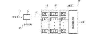
- This sampling system includes a mixing unit 17, a time delay control unit 19, a sampling unit 21, and a signal processing unit 23.
- the mixing unit 17 is connected to the propagation path 13 through which the signal under measurement 11 propagates, and is an element that mixes the signal under measurement 11 propagated through the propagation path 13 and the reference signal 15.
- the time delay control unit 19 obtains a main sampling point from the signal to be measured and the reference signal mixed by the mixing unit with a repetition period less than half of the band frequency of the signal to be measured, and performs sampling at a predetermined time difference from the main sampling point. To obtain sub-sampling points.
- the sampling part 21 is an element for obtaining an amplitude difference or ratio, a phase difference or ratio, and a frequency difference or ratio between a signal under measurement and a reference signal at each sampling point (each main sampling point and each sub-sampling point). is there.
- the signal processing unit 23 Find the time difference ( ⁇ t) between the main sampling point and the sub-sampling point, An amplitude difference ( ⁇ A) which is a difference in amplitude or ratio between the signal under measurement and the reference signal at the main sampling point and the sub sampling point, and a phase difference between the signal under measurement and the reference signal at the main sampling point and the sub sampling point Or a phase difference ( ⁇ ) that is a difference in ratio and a frequency difference ( ⁇ f) that is a difference in frequency or ratio between the signal under measurement and the reference signal at the main sampling point and the sub-sampling point; Using the time difference ( ⁇ t), amplitude difference ( ⁇ A), phase difference ( ⁇ ) and frequency difference ( ⁇ f) between the main sampling point and the sub-sampling point, Obtain the amplitude variation, phase variation, and frequency variation of the signal under measurement.
- ⁇ A amplitude difference
- ⁇ f frequency difference
- the sampling system 25 includes a reference signal fluctuation acquisition unit 27 for obtaining amplitude fluctuation, phase fluctuation, and frequency fluctuation of a reference signal between a main sampling point and a sub sampling point; Using the amplitude variation, phase variation, and frequency variation of the reference signal, What further has the compensation part 29 which compensates the sampling signal sampled in the sampling part 21 or the signal processing part 23 is preferable.
- the sampling system 25 includes a time delay control unit 35, a mixing unit 39, a sampling unit 41, and a signal processing unit 43.
- the time delay control unit 35 is connected to a propagation path 33 through which the signal under measurement 31 propagates, obtains a main sampling point with a repetition period equal to or less than half of the band frequency of the signal under measurement, and has a predetermined time difference from the main sampling point. This is an element for sampling and obtaining sub-sampling points.
- the mixing unit 39 is an element for mixing the signal under measurement output from the time delay control unit 35 and the reference signal 37.
- the sampling part 41 is an element for obtaining an amplitude difference or ratio, a phase difference or ratio, and a frequency difference or ratio between the signal under measurement and the reference signal at each sampling point.
- the signal processing unit 43 Find the time difference ( ⁇ t) between the main sampling point and the sub-sampling point, An amplitude difference ( ⁇ A) which is a difference in amplitude or ratio between the signal under measurement and the reference signal at the main sampling point and the sub sampling point, and a phase difference between the signal under measurement and the reference signal at the main sampling point and the sub sampling point Or a phase difference ( ⁇ ) that is a difference in ratio and a frequency difference ( ⁇ f) that is a difference in frequency or ratio between the signal under measurement and the reference signal at the main sampling point and the sub-sampling point; Using the time difference ( ⁇ t), amplitude difference ( ⁇ A), phase difference ( ⁇ ) and frequency difference ( ⁇ f) between the main sampling point and the sub-sampling point, This is an element for obtaining the amplitude fluctuation, phase fluctu
- FIG. 1 is a flowchart for explaining the sampling method of the present invention.
- FIG. 2 is a block diagram for explaining the sampling system of the present invention.
- FIG. 3 is a block diagram for explaining the sampling system of the present invention.
- FIG. 4 is a partial view of a sampling system having a reference signal fluctuation acquisition unit which is a preferred example of this sampling system.
- FIG. 5 is a block diagram for explaining the sampling system of the present invention.
- FIG. 6 is a block diagram of elements for providing a time delay.
- FIG. 7 is a block diagram of elements for providing a time delay.
- FIG. 8 is a block diagram showing a QPSK signal monitoring system using the dual sampling technique of the present invention.
- FIG. 9 is a diagram for explaining coherent sampling.
- FIG. 10 is a diagram for explaining coherent sampling.
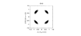
- FIG. 11 shows an example of a measured constellation.
- FIG. 12 shows an example of the measured constellation.
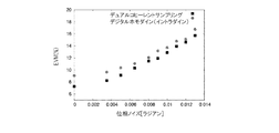
- FIG. 13 shows the observed error vector amplitude (EVM) for
- FIG. 1 is a flow for explaining the sampling method of the present invention.
- S indicates a step (process), but the process is a concept for explaining the sampling method of the present invention, and is not necessarily intended to be performed in this order.
- This sampling method is to obtain the amplitude variation, phase variation, and frequency variation of the signal under measurement, and includes the steps shown in FIG.
- the main sampling step is a step of obtaining sampling points (sampling points) with a repetition period of half or less of the band frequency of the signal under measurement to be measured.
- Obtaining a sampling point (sampling point) means performing measurement (sampling) and obtaining various data at that time.
- the signal under measurement and the reference signal may be an optical signal, a radio signal, or an electrical signal.
- a preferred example of the signal under measurement is a coherent signal, and a coherent optical signal or a high-speed coherent signal is particularly preferable.
- a specific example of the coherent signal is a coherent signal of 100 gigabits / second or more, and may be a coherent signal of 1000 gigabits / second or more.
- Examples of signals are an optical PSK signal, an optical QAM signal, an optical ASK signal, an optical FSK signal, an optical CPFSK signal, an optical APSK signal, and an optical MSK signal (see Japanese Patent No. 5099506).
- Examples of the reference light are continuous (CW) light, pulse light, and optical comb signal (see Japanese Patent Nos. 5665038 and 5299859).
- the amplitude, phase, and frequency of the signal under measurement and the reference signal are measured with respect to the signal obtained by mixing the signal under measurement and the reference signal.
- the time when the main sampling is performed may be stored.
- all of an amplitude, a phase, and a frequency may be measured, any of these may be measured, and another element may be measured.
- the band frequency of the signal under measurement means the frequency range between the lowest frequency and the highest frequency of the signals used for propagation.
- the band frequency may be a value determined by the type of signal under measurement.
- band frequency of the signal under measurement examples are 106 MHz and 48 MHz.
- the band frequency of the signal under measurement may be 1 Hz or more and 10 THz or less, may be 1 MHz or more and 1 THz or less, may be 1 MHz or more and 1 GHz or less, and may be 1 MHz or more and 100 MHz or less. Further, the band frequency of the signal under measurement may be a DC frequency (0 Hz) or higher.
- the main sampling process is performed with a repetition period that is less than half the band frequency of the signal under measurement to be measured. This period may be 1/3 or less, 1/10 or less, or 1/20 or less of the band frequency of the signal under measurement. If sampling is performed at a low frequency, the number of processes is reduced, so that heat generated from the circuit can be reduced, and as a result, fluctuations and distortions derived from the heat can be reduced.
- Sampling may be performed using a known sampling device.
- the sub-sampling step (S120) is a step for obtaining a sub-sampling point by performing sampling different from the main sampling point.
- the subsampling may be performed with the same cycle as the main sampling or may not be performed with the same cycle. Further, the sub-sampling point may be after or before the main sampling in terms of time.
- the sub-sampling step (S120) is schematically shown after the main sampling step (S110) in the figure, these steps are usually performed in parallel (simultaneously).
- the amplitude, phase, and frequency of the signal under measurement and the reference signal are measured with respect to the signal obtained by mixing the signal under measurement and the reference signal.
- the time when the sub-sampling is performed may be stored.
- all of an amplitude, a phase, and a frequency may be measured, any of these may be measured, and another element may be measured.
- the time difference ( ⁇ t) between the sub-sampling points with respect to a certain main sampling point is short.
- a range in which the phase fluctuation of the reference signal at the main sampling point and the sub-sampling point is 1/10 or less is preferable.
- the phase fluctuation of the reference signal at the main sampling point and the sub-sampling point is 1/10 or less means that the value obtained by subtracting the smaller one from the larger of the phases of the reference signal at the main sampling point and the sub-sampling point is larger It means that the value divided by the value of 1/10 or less.
- This phase variation may be adjusted to be 1/15 or less, 1/20 or less, 1/50 or less, or 1/100 or less.
- the time difference ( ⁇ t) is adjusted by taking the phase fluctuation as an example, and the time difference may be adjusted using amplitude fluctuation or frequency fluctuation instead of the phase fluctuation. Since the phase fluctuation has a larger fluctuation amount than the amplitude fluctuation and the frequency fluctuation, if the phase fluctuation is equal to or less than a predetermined value, it is statistically estimated that the amplitude fluctuation and the frequency fluctuation are equal to or less than the values. The For this reason, when the time difference ( ⁇ t) is controlled using any one variation value, it is preferable to control the time difference ( ⁇ t) using the phase variation value.
- two or more of the phase variation, amplitude variation, and frequency variation of the reference signal are 1/10 or less (1/15 or less, 1/20 or less, 1/50 or less, or 1/100 or less). You may adjust so that it may become.
- the time difference ( ⁇ t) should be set so that the hypothesis is rejected in various statistical tests (for example, t test) when a hypothesis based on the measured variation is established. You can also.
- the time difference between the main sampling point and the sub-sampling point is shorter than the coherence time of the signal under measurement (the coherence time of the beat component of the signal under measurement and the reference signal). If the signal under measurement and the reference signal are continuous light, and the phase variation is less than plus or minus ⁇ , the optical phase difference measured at the main sampling point and sub-sampling point is the optical phase shift ( Fluctuation amount).
- the number of sub-sampling points for one main sampling point may be one, or two or more.
- weighting by three-point measurement can be performed, and if there is three-point measurement, an abnormal value can be determined as a non-adopted point, and measurement accuracy can be improved.
- sampling can be performed appropriately by adopting the following steps.
- Sub-sampling may be performed using a known sampling device.
- the sub-sampling may be performed using the same sampling device as the main sampling, or may be performed using another sampling device (sub-sampling device).
- the sampling result is preferably sent to one signal processing device (for example, a computer).
- a step of obtaining a difference or ratio between the signal under measurement and the reference signal includes an amplitude difference or ratio, a phase difference or ratio between the signal under measurement and the reference signal at each sampling point (main sampling point and sub-sampling point), and It is a step of obtaining a frequency difference or ratio.
- each main sampling point has a corresponding one or more sub-sampling points
- sampling data at the main sampling point and the sub-sampling point (the amplitude, phase, and phase of the signal under measurement and the reference signal)
- the amplitude difference, phase difference, and frequency difference are differences in amplitude, phase, and frequency between the signal under measurement and the reference signal.
- the amplitude ratio, phase ratio, and frequency ratio are ratios of the amplitude, phase, and frequency of the signal under measurement and the reference signal.
- the amplitude difference between the signal under measurement and the reference signal can be obtained by obtaining the difference between the amplitude of the signal under measurement at the main sampling point or the sub-sampling point and the amplitude of the reference signal.
- the amplitude ratio between the signal under measurement and the reference signal can be obtained by dividing the amplitude of the signal under measurement at the main sampling point or the sub-sampling point by the amplitude of the reference signal.
- the preferable sampling method of the present invention further includes the following steps.
- Step of obtaining reference signal fluctuation is a step of obtaining the amplitude variation, phase variation, and frequency variation of the reference signal between the main sampling point and the sub-sampling point.
- the phase variation of the reference signal between the main sampling point and the sub-sampling point may be measured, and the amplitude variation or the frequency variation may be obtained from the actually measured value.
- Other fluctuations may be statistically estimated from actually measured values, or amplitude fluctuations and frequency fluctuations corresponding to phase fluctuations are stored in advance, and amplitude fluctuations and frequency fluctuations are measured using the measured phase fluctuations. You may ask for. Similarly, amplitude fluctuations or frequency fluctuations may be measured to determine the remaining fluctuations.
- Step of obtaining sampling correction value uses the amplitude variation, phase variation, and frequency variation of the reference signal obtained in the step (S131) for obtaining the variation of the reference signal. This is a step of obtaining a sampling correction value.
- Step of obtaining time difference ( ⁇ t) is a step of obtaining the time difference ( ⁇ t) between the main sampling point and the sub-sampling point.
- the time difference ( ⁇ t) between the main sampling point and the sub-sampling point may be set using the set time difference.
- the time difference ( ⁇ t) may be obtained by measuring the sampling time of the main sampling point and the sub-sampling point and using the difference.
- a step of obtaining a difference between the main sampling point and the sub sampling point (S150) is a step of obtaining the amplitude difference ( ⁇ A), phase difference ( ⁇ ), and frequency difference ( ⁇ f) between the main sampling point and the sub-sampling point.
- this process includes the amplitude difference or ratio difference ( ⁇ A), phase difference or ratio difference ( ⁇ ), and frequency difference or ratio difference between the non-measurement signal and the reference signal at the main sampling point and the sub-sampling point ( This is a step of obtaining ⁇ f).
- the amplitude difference or ratio, phase difference or ratio, and frequency difference or ratio between the signal under measurement and the reference signal at the main sampling point Since the amplitude difference or ratio, phase difference or ratio, and frequency difference or ratio between the signal under measurement and the reference signal are determined, the amplitude difference or ratio, phase difference or ratio between the main sampling point and the corresponding sub-sampling point, and The frequency difference or ratio is compared, and the amplitude difference ( ⁇ A), phase difference ( ⁇ ), and frequency difference ( ⁇ f), which are these differences, are obtained.
- the amplitude difference ( ⁇ A) between the main sampling point and the sub-sampling point may be obtained.
- Step of determining amplitude variation, phase variation, and frequency variation of the signal under measurement includes the time difference ( ⁇ t), amplitude difference ( ⁇ A), phase difference ( ⁇ ), and frequency difference ( ⁇ f) between the main sampling point and the sub-sampling point. ) To obtain amplitude variation, phase variation, and frequency variation of the signal under measurement.
- the preferred sampling method of the present invention has two sub-sampling points for each main sampling point. If there are two sub-sampling points, the sub-sampling point that becomes an abnormal value from the value of the main sampling point can be excluded from the measurement. Further, if there are two sub-sampling points, three measurement values including the main sampling point can be obtained, so that a more accurate variation value can be obtained.
- the signal distortion amount (compensation value) of the signal under measurement is obtained using any one or two or more fluctuation amounts of the obtained amplitude variation, phase variation, and frequency variation of the signal under measurement.
- the process of obtaining the signal distortion amount (compensation value) of the signal under measurement based on amplitude fluctuation, phase fluctuation, and frequency fluctuation is well known. That is, since the fluctuation value becomes a distortion of the signal, if the amount of distortion is compensated, the original signal from which the distortion component is removed can be restored (demodulated). That is, the present invention is used to obtain the signal distortion amount (compensation value) of the signal under measurement using the amplitude fluctuation, phase fluctuation, and frequency fluctuation of the signal under measurement obtained as described above. Then, using the obtained signal distortion amount (compensation value) of the signal under measurement, the distortion of the signal under measurement is compensated, or when measuring the signal under measurement, the distortion is corrected to obtain a measurement signal. May be.
- the present invention may further include a step of obtaining a transfer function of the transmission medium using the distortion amount (compensation value) obtained as described above. If the transfer function of the transmission medium is obtained, the distortion amount (compensation value) when the same transmission medium is used can be predicted when different signals to be measured are demodulated in the future.
- FIG. 2 is a block diagram for explaining the sampling system of the present invention.
- the sampling system includes a mixing unit 17, a time delay control unit 19, a sampling unit 21, and a signal processing unit 23.
- the optical signals are mixed in the mixing unit.
- the optical signal may be photoelectrically converted and processed as an electrical signal.
- the mixing unit 17 is connected to the propagation path 13 through which the signal under measurement 11 propagates, and is an element that mixes the signal under measurement 11 propagated through the propagation path 13 and the reference signal 15.
- the mixing unit may be a coupler or an optical complex mixer.
- the mixing unit 17 can use a heterodyne mixer or an all-optical mixer in addition to a homodyne mixer.
- the time delay control unit 19 obtains a main sampling point from the signal under measurement and the reference signal mixed by the mixing unit with a repetition period equal to or less than half the band frequency of the signal under measurement, and performs sampling separately from the main sampling point. , Is an element for obtaining sub-sampling points.
- the optical signal is branched, and a time delay is given to each branched signal.
- the time delay may be adjusted by changing the optical path length, or may be adjusted to a predetermined time delay using a known method such as an electrical method of applying a voltage to the waveguide or a change of the temperature of the waveguide.
- the sampling part 21 is an element for obtaining an amplitude difference or ratio, a phase difference or ratio, and a frequency difference or ratio between a signal under measurement and a reference signal at each sampling point (each main sampling point and each sub-sampling point). is there. It suffices that the sampling unit has a detection system such as a sampler so that desired information can be measured.
- An example of the sample portion 21 is a known sampler.
- the sampler preferably has a band that is equal to or higher than the frequency band of the signal under measurement (a band that covers the frequency band of the signal under measurement).
- the signal processing unit 23 obtains a time difference ( ⁇ t) between the main sampling point and the sub-sampling point, and obtains an amplitude difference ( ⁇ A), a phase difference ( ⁇ ), and a frequency difference ( ⁇ f) between the main sampling point and the sub-sampling point. Using the time difference ( ⁇ t), amplitude difference ( ⁇ A), phase difference ( ⁇ ), and frequency difference ( ⁇ f) between the main sampling point and the sub-sampling point, the amplitude variation, phase variation, and frequency variation of the signal under measurement are obtained. It is an element for.
- An example of the signal processing unit 23 is a computer.
- the computer has a storage unit, a calculation unit, and a control unit. Based on the instructions of the control program, the computer reads out necessary information, performs various calculations, and stores it in the storage unit as appropriate. In addition, the operation results can be output from the input / output unit.
- FIG. 3 is a block diagram for explaining the sampling system of the present invention.
- an electric signal and a reference signal are input to the complex mixer and mixed in the complex mixer.
- the subsequent processing is the same as the system in FIG.
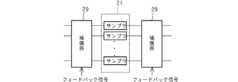
- FIG. 4 is a partial view of a sampling system having a reference signal fluctuation acquisition unit which is a preferred example of this sampling system.
- the sampling system 25 includes a reference signal fluctuation acquisition unit 27 that obtains amplitude fluctuation, phase fluctuation, and frequency fluctuation of a reference signal between a main sampling point and a sub-sampling point, and amplitude fluctuation, phase fluctuation, and frequency fluctuation of the reference signal.
- a sampling system having a compensation unit is known as described in, for example, Japanese Patent No. 5598958 and Japanese Patent No. 5522572.
- the feedback signal in FIG. 4 is output from, for example, the signal processing unit 23 or the compensation unit 27 in FIG. 2 or FIG.
- the feedback signal in FIG. 4 may be used as a feedback signal by calculating a compensation value using the amplitude and amplitude variation of the reference signal, the phase and phase variation of the reference signal, and the frequency and frequency variation of the reference signal. These values may be used as feedback signals by the signal processing unit performing arithmetic processing on measured values from a separately provided sensor. Since the feedback signal includes information on the value and fluctuation of the reference signal, appropriate compensation may be performed using the value. In this compensation, the input signal itself may be compensated before the signal is input to the sampler, or appropriate compensation may be given to the signal output from the sampler.
- FIG. 5 is a block diagram for explaining the sampling system of the present invention.
- the sampling system 25 includes a time delay control unit 35, a mixing unit 39, a sampling unit 41, and a signal processing unit 43.
- the time delay control unit 35 is connected to a propagation path 33 through which the signal under measurement 31 propagates, obtains a main sampling point with a repetition period equal to or less than half of the band frequency of the signal under measurement, and has a predetermined time difference from the main sampling point. This is an element for sampling and obtaining sub-sampling points.
- the mixing unit 39 is an element for mixing the signal under measurement output from the time delay control unit 35 and the reference signal 37.
- the sampling part 41 is an element for obtaining an amplitude difference or ratio, a phase difference or ratio, and a frequency difference or ratio between the signal under measurement and the reference signal at each sampling point.
- the signal processing unit 43 obtains a time difference ( ⁇ t) between the main sampling point and the sub-sampling point, and obtains an amplitude difference ( ⁇ A), a phase difference ( ⁇ ), and a frequency difference ( ⁇ f) between the main sampling point and the sub-sampling point. Using the time difference ( ⁇ t), amplitude difference ( ⁇ A), phase difference ( ⁇ ), and frequency difference ( ⁇ f) between the main sampling point and the sub-sampling point, the amplitude variation, phase variation, and frequency variation of the signal under measurement are obtained. It is an element for.
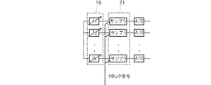
- FIG. 6 is a block diagram of elements for giving a time delay.
- the signal is delayed in a manner different from that described above.
- a signal from a mixing unit such as a complex mixer is branched, a delay is given to each branched signal, and then the signal is input to the sampler.
- a clock signal is input to the sampler and is synchronized.
- FIG. 7 is a block diagram of elements for giving a time delay.
- the signal is delayed in a manner different from that described above.
- a signal from a mixing unit such as a complex mixer is branched, and each branched signal is input to a sampler.
- the clock signal is also branched so as to correspond to each sampler, and a delay signal is mixed with each branched clock signal and input to each sampler.
- the signal distortion amount (compensation value) of the signal under measurement is calculated using any one or two or more fluctuation amounts of the obtained amplitude variation, phase variation, and frequency variation of the signal under measurement.
- the sampling system of the present invention compensates the distortion of the signal under measurement using the obtained signal distortion amount (compensation value) of the signal under measurement or corrects the distortion when measuring the signal under measurement.
- a demodulator for obtaining a signal for use may be included.
- the sampling system of the present invention may further include a medium information obtaining unit that obtains a transfer function of the transmission medium using the distortion amount (compensation value) obtained as described above.
- FIG. 8 is a block diagram showing a QPSK signal monitoring system using the dual sampling technique of the present invention.
- the dual sampling technology of the present invention was evaluated using a high-speed real-time oscilloscope and offline signal processing.
- the 10-GbaudQPSK signal generated by our I / Q modulator is mixed with local light, which is continuous light, using a phase diversity system (90 ° hybrid coupler after balance detection). It was.
- the I and Q components of the detection signal were observed with a 50GSa / s real-time oscilloscope and sent to an off-line DSP section.
- the following functions were emulated in the offline DSP section.
- (b) Dual coherent sampling and
- (c) Low speed DSP for estimating the phase of the carrier In the first part, the received signal was mixed with numerically controlled local continuous light.
- the 90-degree optical hybrid coupler separates the input signal into a Q component and an I component.
- the sampler detects the Q component and the I component separated by the 90-degree optical hybrid, respectively.
- the optical multilevel signal 16QAM and various optical multilevel signals can be adopted in addition to QPSK (quaternary phase shift keying). Specific examples of the optical multilevel signal are 8PSK, 32QAM, 64QAM, 128QAM, and 256QAM.
- the I component and the Q component which are projection components of the received signal onto the optical oscillator, are observed by the 90-degree hybrid coupler and subsequent balanced detection.
- the observed I component and Q component are input to a digital signal processor (DSP) system in order to recover the carrier phase.
- DSP digital signal processor
- the carrier phase of the received signal is obtained by a digital signal processing algorithm similar to digital coherent detection (S. Tsukamoto, et al, OFC2005, PDP29; C. Zhang et al, OFC'09, OTuG3, 2009; H. Sun et al, Opt. Express 16, pp. 873-8792008 (2008)), recovered using the sampled I and Q components.
- detection-drive feedback technology is implemented by DSP.
- DSP digital signal processing for carrier phase recovery can be performed in real time using a low-speed electric DSP having a low cost and a sampling speed of several megahertz.
- the DSP has a loop filter to obtain an error signal for feedback.
- Each sampler has an optical multilevel signal of f / nHz where the frequency of the optical multilevel signal is fHz (n is an integer of 2 or more, and a specific example of n is an integer of 10 2 or more and 10 7 or less. , And an integer of 5 ⁇ 10 2 to 10 5 ).
- fHz frequency of the optical multilevel signal
- n is an integer of 2 or more, and a specific example of n is an integer of 10 2 or more and 10 7 or less.
- an integer of 5 ⁇ 10 2 to 10 5 the complex component is down-converted and sampled at low speed. That is, the low-speed sampler functions as a broadband rate converter.
- Digital signal processor electrically restores each complex component from sampler-sampled optical multilevel signal.
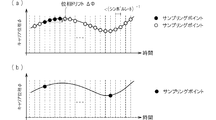
- FIG. 9A shows full-rate sampling (oversampling) typically used in the conventional digital homodyne (intradyne) detection.
- the carrier phase of the received signal is estimated based on a plurality of sampling points obtained continuously, and in addition to the function for obtaining a constellation, the carrier phase drift due to laser phase noise is also analyzed.
- FIG. 9 (b) shows equivalent sampling by a single coherent sampling system which is the prior art. Sampling to obtain a constellation is performed at a considerably low speed of about 10 to 100 MSa / s, for example. However, this method cannot grasp the phase fluctuation at the sampling point. Therefore, carrier phase fluctuations cannot be analyzed.
- FIG. 10 illustrates the dual sampling concept of the present invention.
- an intermediate value between the phase at the main sampling point and the phase at the sub-sampling point is estimated as the carrier phase.
- FIG. 11 (b) shows the constellation measured by a single set coherent sampling system at 500 MSa / s. In this method, the phase drift cannot be tracked, and as a result, it is apparent that the phase drift is not grasped.
- FIG. 12 is a constellation obtained using the dual coherent sampling system of the present invention. Using dual coherent sampling and a conventional digital homodyne receiver, the QPSK constellation damaged by laser drift is clearly restored.
- FIG. 13 shows the observed error vector amplitude (EVM) for laser phase noise when phase noise is added to the emulator.
- EVM error vector amplitude
- the present invention can be used in the fields of optical communication, radio and telecommunications.
Landscapes
- Physics & Mathematics (AREA)
- Engineering & Computer Science (AREA)
- Computer Networks & Wireless Communication (AREA)
- Signal Processing (AREA)
- General Physics & Mathematics (AREA)
- Electromagnetism (AREA)
- Chemical & Material Sciences (AREA)
- Analytical Chemistry (AREA)
- Optical Communication System (AREA)
- Digital Transmission Methods That Use Modulated Carrier Waves (AREA)
- Photometry And Measurement Of Optical Pulse Characteristics (AREA)
Abstract
【解決課題】 低速サンプリングを行っても,光位相変動をとらえ,低コストかつ簡易に被測定信号に対するサンプリング(信号測定)及び解析を実現する。 【解決手段】 測定対象となる被測定信号の帯域周波数の半分以下の繰り返し周期でメインサンプリングポイントを得る工程と,メインサンプリングポイントとは別にサンプリングを行いサブサンプリングポイントを得る工程と,各サンプリングポイントにおける被測定信号と参照信号の振幅差,位相差及び周波数差を得る工程と,メインサンプリングポイントとサブサンプリングポイントの時間差,振幅差(ΔA),位相差(Δφ)及び周波数差(Δf)を得る工程と,メインサンプリングポイントとサブサンプリングポイントの時間差(Δt),振幅差(ΔA),位相差(Δφ)及び周波数差(Δf)を用いて,被測定信号の振幅変動,位相変動及び周波数変動を求める工程とを含むサンプリング方法。
Description
この発明は,信号のサンプリング方法やサンプリングのためのシステムに関する。
信号の多重化が急速に進められている。たとえば,時間領域では数10~100の光信号チャネルが多重化され,光伝送速度は,100ギガb/s~数テラb/sに迫っている。さらに複雑な光多重方式も注目を集めている。そのような光多重方式の例は,光位相シフトキーイング(光PSK),及び光直行振幅変調(光QAM)などのコヒーレント光伝送方式や,光直交周波数分割多重(光OFDM),及び光符号分割多重(光OCDM)である。このような光信号を計測するために,リアルタイム(フルレート)サンプリングオシロスコープに基づくコヒーレント光測定器が使用されている。これは,測定対象となる光信号を時間軸上でシンボルレート又はそれ以上の頻度で高速サンプリングを行い,サンプリング点を基に被測定信号の評価を行うものである。
特に,コヒーレント光信号のサンプリングを行う場合,被測定信号のキャリア信号に対する光位相同期が必要であり,これらの信号処理は,デジタル信号処理によって行われる。この場合,サンプリング点を取得する頻度(レート)は高速であり,実時間での信号処理は困難である。そのため,信号処理回路が並列化される。また,取得されたサンプリング点におけるデータは,大規模のメモリに一度記憶された後に処理されるため,実際の処理はオフライン処理される。このため,従来の装置では,被測定信号のシンボルレート以上の高速サンプリングシステムまたはアナログデジタル変換器が必要となる。
コヒーレント信号に対して低速サンプリングを行うと,位相情報が喪失するので,位相変動を計測し,評価できなくなる。たとえば,光ファイバ通信を想定した場合,光位相変動の例は,光キャリアや局所光として用いられるレーザー信号の位相揺らぎが大きな要因である。さらに,光ファイバ中の波長分散や非線形効果によっても光位相が変動する。そして,これらの変動は,きわめて高速に生じ,各シンボルの波形歪みの原因となる。上記のとおり,低速サンプリングを行う場合は,上記の光位相変動をとらえることができなくなる。
一方,非コヒーレント光信号を計測するために,サンプリングオシロスコープが用いられる。この方法は,低速サンプリングにより,光信号を間引いて光信号の時間波形を取得し,評価するものである。この方法は,アイパターン測定や,固定パターンの時間波形測定を行うことができるため,高速光信号の測定方法として標準的に用いられる。しかしながら,この方法は,被測定信号光が強度変調光に限定され,強度変化を測定できるものの,光位相を測定することはできない。
特許5598958号公報には,復調器が記載されている。この復調器は,超高速な光多値信号を低速にダウンコンバージョンしてサンプリングし,この低速サンプルに基づいて複素信号を電気的に復調して,その復調した複素信号に基づいて局発光をフィードバックして位相同期動作を行うことで,超高速な光多値信号と位相同期信号とが干渉し,これにより低速な複素復調回路により複素情報を復調できるというものである。
特許5522572号公報には,光MSK変調/任意偏移量CPFSKの光サンプリング復調方法が記載されている。この技術は,光位相連続周波数変調(CPFSK)信号のI成分及びQ成分ごとにバランスド検波を行い,サンプリング信号を用いて搬送波の位相を推測して,位相同期検波を行うことで,CPFSK信号を復調できるというものである。
D.Derickson,Prentive Hall PTR,1998
H.Takara et al, Electron. lett., 1152-1153(1994).
本発明は,低速サンプリングを行っても,光位相変動及び高周波信号をとらえ,低コストかつ簡易に被測定信号に対するサンプリング(信号測定)及び解析を実現することを目的とする。
本発明は,基本的には,測定対象となる被測定信号の帯域周波数の半分以下の繰り返し周期という極めて低い周期でサンプリングを行っても,所定のサブサンプリングと組み合わせることにより,被測定信号の振幅変動,位相変動,及び周波数変動を,統計学的に正確に求めることができるという知見に基づくものである。
本出願のサンプリング方法に関する発明を説明する。このサンプリング方法は,被測定信号の振幅変動,位相変動,及び周波数変動を求めるものであり,以下の工程を含む。
測定対象となる被測定信号の帯域周波数の半分以下の繰り返し周期でメインサンプリングポイントを得る工程(S110)。
メインサンプリングポイントとは別にサンプリングを行い,サブサンプリングポイントを得る工程(S120)。
各サンプリングポイントにおける,被測定信号と参照信号の振幅差又は比,位相差又は比,及び周波数差又は比を得る工程(S130)。
メインサンプリングポイントとサブサンプリングポイントの時間差(Δt)を得る工程(S140)。
メインサンプリングポイントとサブサンプリングポイントの振幅差(ΔA),位相差(Δφ),及び周波数差(Δf)を求める工程(S150)。
メインサンプリングポイントとサブサンプリングポイントの時間差(Δt),振幅差(ΔA),位相差(Δφ)及び周波数差(Δf)を用いて,被測定信号の振幅変動,位相変動,及び周波数変動を求める工程(S160)。
メインサンプリングポイントとは別にサンプリングを行い,サブサンプリングポイントを得る工程(S120)。
各サンプリングポイントにおける,被測定信号と参照信号の振幅差又は比,位相差又は比,及び周波数差又は比を得る工程(S130)。
メインサンプリングポイントとサブサンプリングポイントの時間差(Δt)を得る工程(S140)。
メインサンプリングポイントとサブサンプリングポイントの振幅差(ΔA),位相差(Δφ),及び周波数差(Δf)を求める工程(S150)。
メインサンプリングポイントとサブサンプリングポイントの時間差(Δt),振幅差(ΔA),位相差(Δφ)及び周波数差(Δf)を用いて,被測定信号の振幅変動,位相変動,及び周波数変動を求める工程(S160)。
各メインサンプリングポイントに対するサブサンプリングポイントは,1つ又は2つ以上であってもよいが,本発明のサンプリング方法の好ましいものは,各メインサンプリングポイントに対するサブサンプリングポイントが1つのものであるが,2つ存在するものも好ましく,2つ以上存在するものでもよい。
本発明のサンプリング方法の好ましいものは,以下の工程をさらに含む。
メインサンプリングポイント及びサブサンプリングポイント間における参照信号の振幅変動,位相変動,及び周波数変動を求める工程(S131)。
求めた参照信号の振幅変動,位相変動,及び周波数変動を用いて,メインサンプリングポイント及びサブサンプリングポイントにおけるサンプリング補正値を求める工程(S133)。
そして,メインサンプリングポイントとサブサンプリングポイントの振幅差(ΔA),位相差(Δφ),及び周波数差(Δf)を求める工程(S140)は,サンプリング補正値と,各サンプリングポイントにおける被測定信号と参照信号の振幅差(又は振幅比),位相差(又は位相比),及び周波数差(又は周波数の比)とを用いて,メインサンプリングポイントとサブサンプリングポイントの振幅差(ΔA),位相差(Δφ),及び周波数差(Δf)を求める工程である。
メインサンプリングポイント及びサブサンプリングポイント間における参照信号の振幅変動,位相変動,及び周波数変動を求める工程(S131)。
求めた参照信号の振幅変動,位相変動,及び周波数変動を用いて,メインサンプリングポイント及びサブサンプリングポイントにおけるサンプリング補正値を求める工程(S133)。
そして,メインサンプリングポイントとサブサンプリングポイントの振幅差(ΔA),位相差(Δφ),及び周波数差(Δf)を求める工程(S140)は,サンプリング補正値と,各サンプリングポイントにおける被測定信号と参照信号の振幅差(又は振幅比),位相差(又は位相比),及び周波数差(又は周波数の比)とを用いて,メインサンプリングポイントとサブサンプリングポイントの振幅差(ΔA),位相差(Δφ),及び周波数差(Δf)を求める工程である。
次に,本出願のサンプリングシステムに関する発明を説明する。このサンプリングシステムは,混合部17,時間遅延制御部19,サンプリグ部21及び信号処理部23を有する。
混合部17は,被測定信号11が伝搬する伝搬路13と接続され,伝搬路13を伝搬した被測定信号11と,参照信号15とを混合する要素である。
時間遅延制御部19は,混合部で混合された被測定信号及び参照信号から,被測定信号の帯域周波数の半分以下の繰り返し周期でメインサンプリングポイントを得るとともに,メインサンプリングポイントと所定の時間差でサンプリングを行い,サブサンプリングポイントを得るための要素である。
サンプリグ部21は,各サンプリングポイント(各メインサンプリングポイントと各サブサンプリングポイント)にて,被測定信号と参照信号の振幅差又は比,位相差又は比,及び周波数差又は比を得るための要素である。
信号処理部23は,
メインサンプリングポイントと,サブサンプリングポイントの時間差(Δt)を求め,
メインサンプリングポイントとサブサンプリングポイントにおける前記被測定信号と参照信号の振幅差又は比の差である振幅差(ΔA),前記メインサンプリングポイントと前記サブサンプリングポイントにおける前記被測定信号と参照信号の位相差又は比の差である位相差(Δφ),及び前記メインサンプリングポイントと前記サブサンプリングポイントにおける前記被測定信号と参照信号の周波数差又は比の差である周波数差(Δf)を求め,
メインサンプリングポイントとサブサンプリングポイントの時間差(Δt),振幅差(ΔA),位相差(Δφ)及び周波数差(Δf)を用いて,
被測定信号の振幅変動,位相変動,及び周波数変動を求める。
混合部17は,被測定信号11が伝搬する伝搬路13と接続され,伝搬路13を伝搬した被測定信号11と,参照信号15とを混合する要素である。
時間遅延制御部19は,混合部で混合された被測定信号及び参照信号から,被測定信号の帯域周波数の半分以下の繰り返し周期でメインサンプリングポイントを得るとともに,メインサンプリングポイントと所定の時間差でサンプリングを行い,サブサンプリングポイントを得るための要素である。
サンプリグ部21は,各サンプリングポイント(各メインサンプリングポイントと各サブサンプリングポイント)にて,被測定信号と参照信号の振幅差又は比,位相差又は比,及び周波数差又は比を得るための要素である。
信号処理部23は,
メインサンプリングポイントと,サブサンプリングポイントの時間差(Δt)を求め,
メインサンプリングポイントとサブサンプリングポイントにおける前記被測定信号と参照信号の振幅差又は比の差である振幅差(ΔA),前記メインサンプリングポイントと前記サブサンプリングポイントにおける前記被測定信号と参照信号の位相差又は比の差である位相差(Δφ),及び前記メインサンプリングポイントと前記サブサンプリングポイントにおける前記被測定信号と参照信号の周波数差又は比の差である周波数差(Δf)を求め,
メインサンプリングポイントとサブサンプリングポイントの時間差(Δt),振幅差(ΔA),位相差(Δφ)及び周波数差(Δf)を用いて,
被測定信号の振幅変動,位相変動,及び周波数変動を求める。
このサンプリングシステム25は,メインサンプリングポイント及びサブサンプリングポイント間における,参照信号の振幅変動,位相変動,及び周波数変動を求める参照信号変動取得部27と,
参照信号の振幅変動,位相変動,及び周波数変動を用いて,
サンプリグ部21又は信号処理部23においてサンプリングされるサンプリング信号を補償する補償部29をさらに有するものが好ましい。
参照信号の振幅変動,位相変動,及び周波数変動を用いて,
サンプリグ部21又は信号処理部23においてサンプリングされるサンプリング信号を補償する補償部29をさらに有するものが好ましい。
本発明のサンプリングシステム25の上記とは別の構成は,以下のものである。
すなわち,このサンプリングシステム25は,時間遅延制御部35と,混合部39と,サンプリグ部41と,信号処理部43とを有する。
時間遅延制御部35は,被測定信号31が伝搬する伝搬路33と接続されており,被測定信号の帯域周波数の半分以下の繰り返し周期でメインサンプリングポイントを得るとともに,メインサンプリングポイントと所定の時間差でサンプリングを行い,サブサンプリングポイントを得るための要素である。
混合部39は,時間遅延制御部35から出力された被測定信号と参照信号37とを混合するための要素である。
サンプリグ部41は,各サンプリングポイントにおける,被測定信号と参照信号の振幅差又は比,位相差又は比,及び周波数差又は比を得るための要素である。
信号処理部43は,
メインサンプリングポイントと,サブサンプリングポイントの時間差(Δt)を求め,
メインサンプリングポイントとサブサンプリングポイントにおける前記被測定信号と参照信号の振幅差又は比の差である振幅差(ΔA),前記メインサンプリングポイントと前記サブサンプリングポイントにおける前記被測定信号と参照信号の位相差又は比の差である位相差(Δφ),及び前記メインサンプリングポイントと前記サブサンプリングポイントにおける前記被測定信号と参照信号の周波数差又は比の差である周波数差(Δf)を求め,
メインサンプリングポイントとサブサンプリングポイントの時間差(Δt),振幅差(ΔA),位相差(Δφ)及び周波数差(Δf)を用いて,
被測定信号の振幅変動,位相変動,及び周波数変動を求めるための要素である。
すなわち,このサンプリングシステム25は,時間遅延制御部35と,混合部39と,サンプリグ部41と,信号処理部43とを有する。
時間遅延制御部35は,被測定信号31が伝搬する伝搬路33と接続されており,被測定信号の帯域周波数の半分以下の繰り返し周期でメインサンプリングポイントを得るとともに,メインサンプリングポイントと所定の時間差でサンプリングを行い,サブサンプリングポイントを得るための要素である。
混合部39は,時間遅延制御部35から出力された被測定信号と参照信号37とを混合するための要素である。
サンプリグ部41は,各サンプリングポイントにおける,被測定信号と参照信号の振幅差又は比,位相差又は比,及び周波数差又は比を得るための要素である。
信号処理部43は,
メインサンプリングポイントと,サブサンプリングポイントの時間差(Δt)を求め,
メインサンプリングポイントとサブサンプリングポイントにおける前記被測定信号と参照信号の振幅差又は比の差である振幅差(ΔA),前記メインサンプリングポイントと前記サブサンプリングポイントにおける前記被測定信号と参照信号の位相差又は比の差である位相差(Δφ),及び前記メインサンプリングポイントと前記サブサンプリングポイントにおける前記被測定信号と参照信号の周波数差又は比の差である周波数差(Δf)を求め,
メインサンプリングポイントとサブサンプリングポイントの時間差(Δt),振幅差(ΔA),位相差(Δφ)及び周波数差(Δf)を用いて,
被測定信号の振幅変動,位相変動,及び周波数変動を求めるための要素である。
低速サンプリングを行っても,光位相変動をとらえ,低コストかつ簡易に被測定信号に対するサンプリング(信号測定)及び解析を実現できる。
以下,図面を用いて本発明を実施するための形態について説明する。本発明は,以下に説明する形態に限定されるものではなく,以下の形態から当業者が自明な範囲で適宜修正したものも含む。
図1は,本発明のサンプリング方法を説明するためのフローである。図中Sは,ステップ(工程)を示すものの,工程は,本発明のサンプリング方法を説明するための概念であって,必ずしもこの順番に行われることを意図したものではない。このサンプリング方法は,被測定信号の振幅変動,位相変動,及び周波数変動を求めるものであり,図1に記載された各工程を含む。
メインサンプリング工程(S110)
メインサンプリング工程は,測定対象となる被測定信号の帯域周波数の半分以下の繰り返し周期でサンプリングポイント(サンプリング点)を得る工程である。サンプリングポイント(サンプリング点)を得るとは,測定(サンプリング)を行って,その時点での各種データを得ることを意味する。被測定信号及び参照信号は,光信号でも無線信号でも電気信号でもよい。被測定信号の好ましい例は,コヒーレント信号であり,特に,コヒーレント光信号か高速コヒーレント信号が好ましい。具体的なコヒーレント信号の例は,100ギガビット/秒以上のコヒーレント信号であり,1000ギガビット/秒以上のコヒーレント信号でもよい。信号の例は,光PSK信号,光QAM信号,光ASK信号,光FSK信号,光CPFSK信号,光APSK信号及び光MSK信号である(特許5099506号公報参照)。参照光の例は,連続(CW)光,パルス光,及び光コム信号(特許5665038号公報及び特許5299859号公報参照)である。
メインサンプリング工程は,測定対象となる被測定信号の帯域周波数の半分以下の繰り返し周期でサンプリングポイント(サンプリング点)を得る工程である。サンプリングポイント(サンプリング点)を得るとは,測定(サンプリング)を行って,その時点での各種データを得ることを意味する。被測定信号及び参照信号は,光信号でも無線信号でも電気信号でもよい。被測定信号の好ましい例は,コヒーレント信号であり,特に,コヒーレント光信号か高速コヒーレント信号が好ましい。具体的なコヒーレント信号の例は,100ギガビット/秒以上のコヒーレント信号であり,1000ギガビット/秒以上のコヒーレント信号でもよい。信号の例は,光PSK信号,光QAM信号,光ASK信号,光FSK信号,光CPFSK信号,光APSK信号及び光MSK信号である(特許5099506号公報参照)。参照光の例は,連続(CW)光,パルス光,及び光コム信号(特許5665038号公報及び特許5299859号公報参照)である。
メインサンプリング工程では,例えば,被測定信号と参照信号とが混合された信号に対し,被測定信号と参照信号の振幅,位相,及び周波数を測定する。この際,メインサンプリングが行われた時間を記憶してもよい。なお,振幅,位相,及び周波数のすべてが測定されてもよいし,これらのうちのいずれかが測定されてもよいし,さらに他の要素が測定されてもよい。
被測定信号の帯域周波数は,伝播に利用する信号の周波数のうち一番低い周波数と一番高い周波数の間の周波数の範囲を意味する。帯域周波数は,被測定信号の種類によって決まっている値であってもよい。
被測定信号の帯域周波数の例は,106MHzや48MHzである。被測定信号の帯域周波数1Hz以上10THz以下であればよく,1MHz以上1THz以下でもよいし,1MHz以上1GHz以下でもよく,1MHz以上100MHz以下でもよい。また,被測定信号の帯域周波数は,DC周波数(0Hz)以上でもよい。
メインサンプリング工程は,測定対象となる被測定信号の帯域周波数の半分以下の繰り返し周期で行われる。この周期は,被測定信号の帯域周波数の1/3以下でも1/10以下でも1/20以下でもよい。低い頻度でサンプリングを行うようにすれば,処理回数が減るため,回路からの発熱を軽減でき,その結果,発熱由来の変動や歪みを軽減できる。
サンプリングは,公知のサンプリング装置を用いて行えばよい。
サブサンプリング工程(S120)
サブサンプリング工程(S120)は,メインサンプリングポイントとは別のサンプリングに行い,サブサンプリングポイントを得る工程である。
サブサンプリングは,メインサンプリングと同じ周期で行ってもよいし,同じ周期でなくても構わない。また,サブサンプリングポイントは,時間的にメインサンプリングの後であっても前であっても構わない。図では模式的にサブサンプリング工程(S120)がメインサンプリング工程(S110)の後のように示されているが,通常これらの工程は並行して(同時に)行われる。
サブサンプリング工程(S120)は,メインサンプリングポイントとは別のサンプリングに行い,サブサンプリングポイントを得る工程である。
サブサンプリングは,メインサンプリングと同じ周期で行ってもよいし,同じ周期でなくても構わない。また,サブサンプリングポイントは,時間的にメインサンプリングの後であっても前であっても構わない。図では模式的にサブサンプリング工程(S120)がメインサンプリング工程(S110)の後のように示されているが,通常これらの工程は並行して(同時に)行われる。
サブサンプリング工程では,例えば,被測定信号と参照信号とが混合された信号に対し,被測定信号と参照信号の振幅,位相,及び周波数を測定する。この際,サブサンプリングが行われた時間を記憶してもよい。なお,振幅,位相,及び周波数のすべてが測定されてもよいし,これらのうちのいずれかが測定されてもよいし,さらに他の要素が測定されてもよい。
あるメインサンプリングポイントに対するサブサンプリングポイントの時間差(Δt)が短いものが好ましい。具体的には,メインサンプリングポイントとサブサンプリングポイントにおける参照信号の位相変動が1/10以下となる範囲とするものが好ましい。メインサンプリングポイントとサブサンプリングポイントにおける参照信号の位相変動が1/10以下とは,メインサンプリングポイントとサブサンプリングポイントにおける参照信号の位相のうち大きい方から小さい方を引いて得られた値を大きい方の値で割った値が1/10以下であることを意味する。この位相変動は,1/15以下,1/20以下,1/50以下又は1/100以下となるように調整されてもよい。上記は,位相変動を例に時間差(Δt)を調整したものであり,位相変動の代わりに振幅変動又は周波数変動を用いて時間差を調整してもよい。位相変動は,振幅変動,及び周波数変動に比べて変動量が大きいので,位相変動が所定の値以下であれば,振幅変動,及び周波数変動はその値以下であることが統計学的に推測される。このため,いずれか1つの変動値を用いて時間差(Δt)を制御する場合は,位相変動の値を用いて,時間差(Δt)を制御することが好ましい。もっとも,時間差(Δt)は,参照信号の位相変動,振幅変動,及び周波数変動の2つ以上が1/10以下(1/15以下,1/20以下,1/50以下又は1/100以下)となるように調整されてもよい。
時間差(Δt)は,測定される変動量に基づく仮説を立てた場合における,各種統計学的検定(たとえばt検定)において,棄却域に入り,仮説が棄却される量となるように設定することもできる。
上記の時間差を定性的に表現すれば,メインサンプリングポイントとサブサンプリングポイントの時間差が,被測定信号のコヒーレンス時間(被測定信号と参照信号のビート成分のコヒーレンス時間)より短いこととなる。被測定信号と参照信号とを連続光とした場合,位相変動量がプラスマイナスπ以下であるときは,メインサンプリングポイントとサブサンプリングポイントにて測定された光位相差は,光位相の変移量(変動量)としてとらえることができる。
1つのメインサンプリングポイントに対するサブサンプリングポイントは,1つでもよいし,2つ以上でもよい。1つのメインサンプリングポイントに対するサブサンプリングポイントが2つの場合は,時間軸に対して非対称信号の測定を行うことができるという技術的メリットがある。また,この場合,3点測定による重みづけができるし,3点測定があれば,異常値を不採用点とすることができ,測定精度を向上させることができる。
あるメインサンプリングポイントに対するサブサンプリングポイントの時間差(Δt)が短いものであっても,短くなくても,以下の工程を採用することで,サンプリングを適切に行うことができる。
サブサンプリングは,公知のサンプリング装置を用いて行えばよい。サブサンプリングは,メインサンプリングと同じサンプリング装置を用いて行われてもよいし,別のサンプリング装置(サブサンプリング装置)を用いて行われてもよい。いずれの場合も,サンプリング結果が,1つの信号処理装置(たとえば,コンピュータ)に送られることが好ましい。
被測定信号と参照信号の差又は比を求める工程(S130)
被測定信号と参照信号の差又は比を求める工程(S130)は,各サンプリングポイント(メインサンプリングポイント及びサブサンプリングポイント)における,被測定信号と参照信号の振幅差又は比,位相差又は比,及び周波数差又は比を得る工程である。
具体的には,それぞれのメインサンプリングポイントには,対応する1又は複数のサブサンプリングポイントが存在するので,メインサンプリングポイントとサブサンプリングポイントにおけるサンプリングデータ(被測定信号と参照信号の振幅,位相,及び周波数値)を用いて,被測定信号と参照信号の振幅差,位相差,及び周波数差,又は振幅比,位相比,及び周波数比を得る工程である。振幅差,位相差,及び周波数差は,被測定信号と参照信号の振幅,位相,及び周波数の差である。振幅比,位相比,及び周波数比は,被測定信号と参照信号の振幅,位相,及び周波数の比である。たとえば,被測定信号と参照信号の振幅差は,メインサンプリングポイント又はサブサンプリングポイントにおける被測定信号の振幅と参照信号の振幅との差を求めることで求めることができる。また,被測定信号と参照信号の振幅比は,メインサンプリングポイント又はサブサンプリングポイントにおける被測定信号の振幅を参照信号の振幅で割ることにより求めることができる。
被測定信号と参照信号の差又は比を求める工程(S130)は,各サンプリングポイント(メインサンプリングポイント及びサブサンプリングポイント)における,被測定信号と参照信号の振幅差又は比,位相差又は比,及び周波数差又は比を得る工程である。
具体的には,それぞれのメインサンプリングポイントには,対応する1又は複数のサブサンプリングポイントが存在するので,メインサンプリングポイントとサブサンプリングポイントにおけるサンプリングデータ(被測定信号と参照信号の振幅,位相,及び周波数値)を用いて,被測定信号と参照信号の振幅差,位相差,及び周波数差,又は振幅比,位相比,及び周波数比を得る工程である。振幅差,位相差,及び周波数差は,被測定信号と参照信号の振幅,位相,及び周波数の差である。振幅比,位相比,及び周波数比は,被測定信号と参照信号の振幅,位相,及び周波数の比である。たとえば,被測定信号と参照信号の振幅差は,メインサンプリングポイント又はサブサンプリングポイントにおける被測定信号の振幅と参照信号の振幅との差を求めることで求めることができる。また,被測定信号と参照信号の振幅比は,メインサンプリングポイント又はサブサンプリングポイントにおける被測定信号の振幅を参照信号の振幅で割ることにより求めることができる。
本発明のサンプリング方法の好ましいものは,以下の工程をさらに含む。
メインサンプリングポイント及びサブサンプリングポイント間における,参照信号の振幅変動,位相変動,及び周波数変動を求める工程(S131)。
求めた参照信号の振幅変動,位相変動,及び周波数変動を用いて,メインサンプリングポイント及びサブサンプリングポイントにおけるサンプリング補正値を求める工程(S133)。
メインサンプリングポイント及びサブサンプリングポイント間における,参照信号の振幅変動,位相変動,及び周波数変動を求める工程(S131)。
求めた参照信号の振幅変動,位相変動,及び周波数変動を用いて,メインサンプリングポイント及びサブサンプリングポイントにおけるサンプリング補正値を求める工程(S133)。
参照信号の変動を求める工程(S131)
参照信号の変動を求める工程は,メインサンプリングポイント及びサブサンプリングポイント間における,参照信号の振幅変動,位相変動,及び周波数変動を求める工程である。この工程は,例えば,メインサンプリングポイント及びサブサンプリングポイント間における,参照信号の位相変動を実測し,実測した値から振幅変動や周波数変動を求めてもよい。これは統計学的に実測値から他の変動を推測してもよいし,あらかじめ位相変動と対応する振幅変動や周波数変動を記憶しておき,実測した位相変動を用いて,振幅変動や周波数変動を求めてもよい。同様にして,振幅変動又は周波数変動を実測して,残りの変動を求めてもよい。
参照信号の変動を求める工程は,メインサンプリングポイント及びサブサンプリングポイント間における,参照信号の振幅変動,位相変動,及び周波数変動を求める工程である。この工程は,例えば,メインサンプリングポイント及びサブサンプリングポイント間における,参照信号の位相変動を実測し,実測した値から振幅変動や周波数変動を求めてもよい。これは統計学的に実測値から他の変動を推測してもよいし,あらかじめ位相変動と対応する振幅変動や周波数変動を記憶しておき,実測した位相変動を用いて,振幅変動や周波数変動を求めてもよい。同様にして,振幅変動又は周波数変動を実測して,残りの変動を求めてもよい。
サンプリング補正値を求める工程(S133)
サンプリング補正値を求める工程(S133)は,上記の参照信号の変動を求める工程(S131)で求めた参照信号の振幅変動,位相変動,及び周波数変動を用いて,メインサンプリングポイント及びサブサンプリングポイントにおけるサンプリング補正値を求める工程である。
サンプリング補正値を求める工程(S133)は,上記の参照信号の変動を求める工程(S131)で求めた参照信号の振幅変動,位相変動,及び周波数変動を用いて,メインサンプリングポイント及びサブサンプリングポイントにおけるサンプリング補正値を求める工程である。
時間差(Δt)を得る工程(S140)
時間差(Δt)を得る工程(S140)は,メインサンプリングポイントとサブサンプリングポイントの時間差(Δt)を得る工程である。
この工程は,メインサンプリングポイントとサブサンプリングポイントがあらかじめ設定された時間差でサンプリングされている場合は,その設定された時間差を用いてメインサンプリングポイントとサブサンプリングポイントの時間差(Δt)としてもよい。また,メインサンプリングポイントとサブサンプリングポイントのサンプリング時間を測定し,差を用いることで時間差(Δt)としてもよい。
時間差(Δt)を得る工程(S140)は,メインサンプリングポイントとサブサンプリングポイントの時間差(Δt)を得る工程である。
この工程は,メインサンプリングポイントとサブサンプリングポイントがあらかじめ設定された時間差でサンプリングされている場合は,その設定された時間差を用いてメインサンプリングポイントとサブサンプリングポイントの時間差(Δt)としてもよい。また,メインサンプリングポイントとサブサンプリングポイントのサンプリング時間を測定し,差を用いることで時間差(Δt)としてもよい。
メインサンプリングポイントとサブサンプリングポイントの差を求める工程(S150)
メインサンプリングポイントとサブサンプリングポイントの差を求める工程(S150)は,メインサンプリングポイントとサブサンプリングポイントの振幅差(ΔA),位相差(Δφ),及び周波数差(Δf)を求める工程である。換言すると,この工程は,メインサンプリングポイントとサブサンプリングポイントにおける非測定信号及び参照信号の振幅差又は比の差(ΔA),位相差又は比の差(Δφ),及び周波数差又は比の差(Δf)を求める工程である。
つまり,被測定信号と参照信号の差を求める工程(S130)で,メインサンプリングポイントにおける被測定信号と参照信号の振幅差又は比,位相差又は比,及び周波数差又は比や,サブサンプリングポイントにおける被測定信号と参照信号の振幅差又は比,位相差又は比,及び周波数差又は比が求められているので,メインサンプリングポイントと対応するサブサンプリングポイントの振幅差又は比,位相差又は比,及び周波数差又は比を比較し,これらの差である振幅差(ΔA),位相差(Δφ),及び周波数差(Δf)を求めるものである。
サンプリング補正値と,各サンプリングポイントにおける被測定信号と参照信号の振幅差又は比,位相差又は比,及び周波数差又は比とを用いて,メインサンプリングポイントとサブサンプリングポイントの振幅差(ΔA),位相差(Δφ),及び周波数差(Δf)を求めてもよい。
メインサンプリングポイントとサブサンプリングポイントの差を求める工程(S150)は,メインサンプリングポイントとサブサンプリングポイントの振幅差(ΔA),位相差(Δφ),及び周波数差(Δf)を求める工程である。換言すると,この工程は,メインサンプリングポイントとサブサンプリングポイントにおける非測定信号及び参照信号の振幅差又は比の差(ΔA),位相差又は比の差(Δφ),及び周波数差又は比の差(Δf)を求める工程である。
つまり,被測定信号と参照信号の差を求める工程(S130)で,メインサンプリングポイントにおける被測定信号と参照信号の振幅差又は比,位相差又は比,及び周波数差又は比や,サブサンプリングポイントにおける被測定信号と参照信号の振幅差又は比,位相差又は比,及び周波数差又は比が求められているので,メインサンプリングポイントと対応するサブサンプリングポイントの振幅差又は比,位相差又は比,及び周波数差又は比を比較し,これらの差である振幅差(ΔA),位相差(Δφ),及び周波数差(Δf)を求めるものである。
サンプリング補正値と,各サンプリングポイントにおける被測定信号と参照信号の振幅差又は比,位相差又は比,及び周波数差又は比とを用いて,メインサンプリングポイントとサブサンプリングポイントの振幅差(ΔA),位相差(Δφ),及び周波数差(Δf)を求めてもよい。
被測定信号の振幅変動,位相変動,及び周波数変動を求める工程(S160)
被測定信号の振幅変動,位相変動,及び周波数変動を求める工程(S160)は,メインサンプリングポイントとサブサンプリングポイントの時間差(Δt),振幅差(ΔA),位相差(Δφ)及び周波数差(Δf)を用いて,被測定信号の振幅変動,位相変動,及び周波数変動を求める工程である。
被測定信号の振幅変動,位相変動,及び周波数変動を求める工程(S160)は,メインサンプリングポイントとサブサンプリングポイントの時間差(Δt),振幅差(ΔA),位相差(Δφ)及び周波数差(Δf)を用いて,被測定信号の振幅変動,位相変動,及び周波数変動を求める工程である。
本発明のサンプリング方法の好ましいものは,各メインサンプリングポイントに対するサブサンプリングポイントが,2つ存在するものである。サブサンプリングポイントが2つ存在すれば,メインサンプリングポイントの値からして異常値となるサブサンプリングポイントを測定から外すことができる。また,サブサンプリングポイントが2つ存在すれば,メインサンプリングポイントと合わせて3点の測定値が得られるため,より正確な変動値を求めることができる。
次に,求めた被測定信号の振幅変動,位相変動,及び周波数変動のいずれか1つ又は2つ以上の変動量を用いて,被測定信号の信号歪み量(補償値)を求める。振幅変動,位相変動,及び周波数変動に基づいて被測定信号の信号歪み量(補償値)を求める工程は公知である。つまり,変動値は信号の歪みとなるので,その歪み量分だけ補償すれば,歪み成分を取り除いた本来の信号を復元(復調)できることとなる。
すなわち,本発明は,上記のようにして求めた被測定信号の振幅変動,位相変動,及び周波数変動を用いて,被測定信号の信号歪み量(補償値)を求めるために用いられる。そして,求めた被測定信号の信号歪み量(補償値)を用いて,被測定信号の歪みを補償し,又は被測定信号を測定する際に,歪みを補正して,測定用の信号を得てもよい。
すなわち,本発明は,上記のようにして求めた被測定信号の振幅変動,位相変動,及び周波数変動を用いて,被測定信号の信号歪み量(補償値)を求めるために用いられる。そして,求めた被測定信号の信号歪み量(補償値)を用いて,被測定信号の歪みを補償し,又は被測定信号を測定する際に,歪みを補正して,測定用の信号を得てもよい。
本発明は,さらに,上記のようにして求めた歪み量(補償値)を用いて,伝送媒体の伝達関数を求める工程を含むものであってもよい。伝送媒体の伝達関数を求めれば,今後異なる被測定信号を復調等する場合に,同じ伝送媒体を用いた場合の歪み量(補償値)を予測できることとなる。
次に,本出願のサンプリングシステムに関する発明を説明する。
図2は,本発明のサンプリングシステムを説明するためのブロック図である。
図2に示されるように,このサンプリングシステムは,混合部17,時間遅延制御部19,サンプリグ部21及び信号処理部23を有する。図2では,光信号が混合部で混合されている。しかし,光信号を光電変換し,電気信号として処理するようにしてもよい。
混合部17は,被測定信号11が伝搬する伝搬路13と接続され,伝搬路13を伝搬した被測定信号11と,参照信号15とを混合する要素である。光信号を扱う場合,混合部はカプラや,光複素ミキサであればよい。混合部17は,ホモダインミキサのほかヘテロダインミキサや全光ミキサを用いることができる。 時間遅延制御部19は,混合部で混合された被測定信号及び参照信号から,被測定信号の帯域周波数の半分以下の繰り返し周期でメインサンプリングポイントを得るとともに,メインサンプリングポイントとは別にサンプリングを行い,サブサンプリングポイントを得るための要素である。図2に示される例では,光信号が分岐し,分岐したそれぞれの信号に対して,時間遅延が与えられている。時間遅延は,光路長を変化させることで調整してもよいし,導波路に電圧を印可するといった電気的方法,導波路の温度を変化させるなど,公知の方法を用いて,所定の時間遅延を信号に対して与えることができる。
サンプリグ部21は,各サンプリングポイント(各メインサンプリングポイントと各サブサンプリングポイント)にて,被測定信号と参照信号の振幅差又は比,位相差又は比,及び周波数差又は比を得るための要素である。サンプリング部にはサンプラなどの検出系が存在し,所望の情報を測定できるようにされていればよい。サンプリグ部21の例は,公知のサンプラである。サンプラは被測定信号の周波数帯域以上の帯域(被測定信号の周波数帯域をカバーする帯域)を有するものが好ましい。サンプラの帯域が,被測定信号の周波数帯域より狭い場合,被測定信号のゆがみを許容するか,歪みを補償する機構をさらに有することが好ましい。
信号処理部23は,メインサンプリングポイントと,サブサンプリングポイントの時間差(Δt)を求め,メインサンプリングポイントとサブサンプリングポイントの振幅差(ΔA),位相差(Δφ),及び周波数差(Δf)を求め,メインサンプリングポイントとサブサンプリングポイントの時間差(Δt),振幅差(ΔA),位相差(Δφ)及び周波数差(Δf)を用いて,被測定信号の振幅変動,位相変動,及び周波数変動を求めるための要素である。信号処理部23の例は,コンピュータである。コンピュータは,入出力部の他に,記憶部や,演算部及び制御部を有しており,制御プログラムの指令に基づいて,必要な情報を読み出して,各種演算を行い,適宜記憶部に記憶し,入出力部から演算結果を出力できる。
図2は,本発明のサンプリングシステムを説明するためのブロック図である。
図2に示されるように,このサンプリングシステムは,混合部17,時間遅延制御部19,サンプリグ部21及び信号処理部23を有する。図2では,光信号が混合部で混合されている。しかし,光信号を光電変換し,電気信号として処理するようにしてもよい。
混合部17は,被測定信号11が伝搬する伝搬路13と接続され,伝搬路13を伝搬した被測定信号11と,参照信号15とを混合する要素である。光信号を扱う場合,混合部はカプラや,光複素ミキサであればよい。混合部17は,ホモダインミキサのほかヘテロダインミキサや全光ミキサを用いることができる。 時間遅延制御部19は,混合部で混合された被測定信号及び参照信号から,被測定信号の帯域周波数の半分以下の繰り返し周期でメインサンプリングポイントを得るとともに,メインサンプリングポイントとは別にサンプリングを行い,サブサンプリングポイントを得るための要素である。図2に示される例では,光信号が分岐し,分岐したそれぞれの信号に対して,時間遅延が与えられている。時間遅延は,光路長を変化させることで調整してもよいし,導波路に電圧を印可するといった電気的方法,導波路の温度を変化させるなど,公知の方法を用いて,所定の時間遅延を信号に対して与えることができる。
サンプリグ部21は,各サンプリングポイント(各メインサンプリングポイントと各サブサンプリングポイント)にて,被測定信号と参照信号の振幅差又は比,位相差又は比,及び周波数差又は比を得るための要素である。サンプリング部にはサンプラなどの検出系が存在し,所望の情報を測定できるようにされていればよい。サンプリグ部21の例は,公知のサンプラである。サンプラは被測定信号の周波数帯域以上の帯域(被測定信号の周波数帯域をカバーする帯域)を有するものが好ましい。サンプラの帯域が,被測定信号の周波数帯域より狭い場合,被測定信号のゆがみを許容するか,歪みを補償する機構をさらに有することが好ましい。
信号処理部23は,メインサンプリングポイントと,サブサンプリングポイントの時間差(Δt)を求め,メインサンプリングポイントとサブサンプリングポイントの振幅差(ΔA),位相差(Δφ),及び周波数差(Δf)を求め,メインサンプリングポイントとサブサンプリングポイントの時間差(Δt),振幅差(ΔA),位相差(Δφ)及び周波数差(Δf)を用いて,被測定信号の振幅変動,位相変動,及び周波数変動を求めるための要素である。信号処理部23の例は,コンピュータである。コンピュータは,入出力部の他に,記憶部や,演算部及び制御部を有しており,制御プログラムの指令に基づいて,必要な情報を読み出して,各種演算を行い,適宜記憶部に記憶し,入出力部から演算結果を出力できる。
図3は,本発明のサンプリングシステムを説明するためのブロック図である。この例では,複素ミキサに電気信号と参照信号が入力され,複素ミキサにおいて混合される。この後の処理は,図2におけるシステムと同様である。
図4は,このサンプリングシステムの好ましい例である参照信号変動取得部を有するものの部分図である。このサンプリングシステム25は,メインサンプリングポイント及びサブサンプリングポイント間における,参照信号の振幅変動,位相変動,及び周波数変動を求める参照信号変動取得部27と,参照信号の振幅変動,位相変動,及び周波数変動を用いて,サンプリグ部21又は信号処理部23においてサンプリングされるサンプリング信号を補償する補償部29をさらに有する。補償部29を有するので,このシステムは,参照信号の変動を補償できることとなる。補償部を有するサンプリングシステムは,たとえば,特許5598958号公報及び特許5522572号公報に記載されたとおり公知である。図4におけるフィードバック信号は,たとえば,図2又は図3の信号処理部23又は補償部27から出力される。図4におけるフィードバック信号は,参照信号の振幅及び振幅変動,参照信号の位相及び位相変動,参照信号の周波数及び周波数変動を用いて,補償値が演算され,フィードバック信号とされてもよい。これらの値は,別に設けられたセンサからの測定値を信号処理部が演算処理し,フィードバック信号とされてもよい。フィードバック信号は,参照信号の値や変動に関する情報が含まれているため,その値を用いて適切な補償を行えばよい。この補償は,サンプラに信号が入力される前に入力信号自体を補償してもよいし,サンプラから出力された信号に対して,適切な補償を与えてもよい。
図5は,本発明のサンプリングシステムを説明するためのブロック図である。図5に示されるように,このサンプリングシステム25は,時間遅延制御部35と,混合部39と,サンプリグ部41と,信号処理部43とを有する。時間遅延制御部35は,被測定信号31が伝搬する伝搬路33と接続されており,被測定信号の帯域周波数の半分以下の繰り返し周期でメインサンプリングポイントを得るとともに,メインサンプリングポイントと所定の時間差でサンプリングを行い,サブサンプリングポイントを得るための要素である。
混合部39は,時間遅延制御部35から出力された被測定信号と参照信号37とを混合するための要素である。サンプリグ部41は,各サンプリングポイントにおける,被測定信号と参照信号の振幅差又は比,位相差又は比,及び周波数差又は比を得るための要素である。信号処理部43は,メインサンプリングポイントと,サブサンプリングポイントの時間差(Δt)を求め,メインサンプリングポイントとサブサンプリングポイントの振幅差(ΔA),位相差(Δφ),及び周波数差(Δf)を求め,メインサンプリングポイントとサブサンプリングポイントの時間差(Δt),振幅差(ΔA),位相差(Δφ)及び周波数差(Δf)を用いて,被測定信号の振幅変動,位相変動,及び周波数変動を求めるための要素である。
混合部39は,時間遅延制御部35から出力された被測定信号と参照信号37とを混合するための要素である。サンプリグ部41は,各サンプリングポイントにおける,被測定信号と参照信号の振幅差又は比,位相差又は比,及び周波数差又は比を得るための要素である。信号処理部43は,メインサンプリングポイントと,サブサンプリングポイントの時間差(Δt)を求め,メインサンプリングポイントとサブサンプリングポイントの振幅差(ΔA),位相差(Δφ),及び周波数差(Δf)を求め,メインサンプリングポイントとサブサンプリングポイントの時間差(Δt),振幅差(ΔA),位相差(Δφ)及び周波数差(Δf)を用いて,被測定信号の振幅変動,位相変動,及び周波数変動を求めるための要素である。
図6は,時間遅延を与えるための要素のブロック図である。この例は,先に説明したものとは異なる方法で信号に遅延を与えるものである。この例は,複素ミキサなどの混合部からの信号を分岐し,分岐されたそれぞれの信号にそれぞれ遅延を与えた後,サンプラへ信号が入力される。サンプラへは,クロック信号が入力され,同期が取られている。
図7は,時間遅延を与えるための要素のブロック図である。この例は,先に説明したものとは異なる方法で信号に遅延を与えるものである。この例は,複素ミキサなどの混合部からの信号を分岐し,分岐されたそれぞれの信号がサンプラへ信号が入力される。一方,クロック信号もそれぞれのサンプラに対応するように分岐され,分岐されたそれぞれのクロック信号に遅延信号が混合され,それぞれのサンプラへ入力される。
本発明のサンプリングシステムは,求めた被測定信号の振幅変動,位相変動,及び周波数変動のいずれか1つ又は2つ以上の変動量を用いて,被測定信号の信号歪み量(補償値)を求めるための要素を有していてもよい。このような要素は,信号処理部の一部であってもよいし,信号処理部とは別に設けられてもよい。
本発明のサンプリングシステムは,求めた被測定信号の信号歪み量(補償値)を用いて,被測定信号の歪みを補償し,又は被測定信号を測定する際に,歪みを補正して,測定用の信号を得るための復調部を有してもよい。
本発明のサンプリングシステムは,さらに,上記のようにして求めた歪み量(補償値)を用いて,伝送媒体の伝達関数を求める媒体情報取得部を有してもよい。
図8は,本発明のデュアルサンプリング技術を用いたQPSK信号のモニターシステムを示すブロック図である。
ここで,高速リアルタイムオシロスコープとオフライン信号処理を用いて,本発明のデュアルサンプリング技術を評価した。この装置では,送信器がわのI/Q変調器によって生成された10-GbaudQPSK信号が,位相ダイバーシティ系(バランス検波後の90°ハイブリッドカプラ)を用いて,連続光である局所光と混合された。検出信号のI及びQ成分は,50GSa/s実時間オシロスコープで観測し,オフラインのDSP部へ送られた。オフラインのDSP部では,以下の機能がエミュレートされた。(a)位相ノイズの生成(任意),(b)デュアルコヒーレントサンプリング及び(c)キャリアの位相を推測するための低速DSP。最初の部分では,受信信号は,数値制御された局所連続光と混合された。この部分では,レーザーの位相ノイズの影響を単に評価するため,連続光と所定の量の位相ノイズとを混合しホモダインミキシングをエミュレートした。この部分では,数値制御された局所光の波長を調整することで,受信信号と局所光のレーザー周波数オフセットをキャンセルした。
90度光ハイブリッドカプラは,入力された信号をQ成分とI成分とに分離する。サンプラは,90度光ハイブリッドが分離したQ成分及びI成分をそれぞれ検出する。光多値信号は,QPSK(4値位相シフトキーイング)の他,16QAMやさまざまな光多値信号を採用できる。具体的な光多値信号の例は,8PSK,32QAM,64QAM,128QAM,及び256QAMである。
光位相検出器系では,受信信号のうち光学的オシレータへの射影成分であるI成分及びQ成分が,90度ハイブリットカプラとその後のバランスト検波により観測される。
観測されたI成分及びQ成分は,キャリア位相をリカバリーするために,デジタルシグナルプロセッサ(DSP)系へ入力される。この系では,1組の電気的サンプラを用いてB/nHz(n=1,2,・・・)で低速サンプリングを行う。DSP系では,受信信号のキャリア位相は,デジタルコヒーレント検波と類似したデジタルシグナルプロセッシングアルゴリズムにより(S. Tsukamoto, et al, OFC2005, PDP29;C. Zhang et al, OFC’09, OTuG3, 2009;H. Sun et al, Opt. Express 16, pp. 873-879 (2008).),サンプリングされたI成分及びQ成分を用いてリカバーされる。
本件では,検出-駆動フィードバック技術がDSPにより実装される。そのようなキャリア位相リカバリーのためのシグナルプロセッシングは,低コストでサンプリング速度が数メガヘルツである低速の電気的DSPを用いてもリアルタイムに実行可能である。DSPは,フィードバック用のエラーシグナルを得るためにループフィルタを有する。
次のセクションは,受信された10-GbaudのI/Q信号をダウンコンバートするために,500MSa/sでのデュアルコヒーレントサンプリングが数値的にエミュレートされた。この実施例では,メインとサブサンプリングの時間差τを9ナノ秒とした。500MHzのDSPクロックにて処理することで,ダウンサンプリングしたI/Qシグナルから,コンスタレーションが復元された。メインとサブのDSPは,メインとサブのサンプリング信号から見積もられたキャリアの位相の平均値を取り合うように協働した。実システムでオフライン処理にてエミュレートされたすべての機能を実際の装置で実装する場合は,例えば,光学系と電子的なハードウェアとを用いて実現できる。
各サンプラは,光多値信号の周波数をfHzとすると,光多値信号をf/nHz(nは,2以上の整数であり,具体的なnの例は,102以上107以下の整数,及び5×102以上105以下の整数である)でサンプリングする。このサンプラにより,複素成分が,ダウンコンバージョンされて,低速サンプリングされる。すなわち,低速サンプラが,広帯域レート変換器として機能する。
デジタルシグナルプロセッサ(DSP)は,サンプラサンプリングした光多値信号からそれぞれの複素成分を電気的に復元する。
図9及び図10は,コヒーレントサンプリングを説明するための図である。図9(a)は,従来技術であるデジタルホモダイン(イントラダイン)検出において典型的に用いられるフルレートサンプリング(オーバーサンプリング)を示す。受信信号のキャリア位相は,連続的に取得された複数のサンプリングポイントに基づいて推測され,コンスタレーションを得るための機能に加えて,レーザー位相ノイズによるキャリアの位相ドリフトも分析される。図9(b)は,従来技術である単一コヒーレントサンプリングシステムによる等価サンプリングを示す。コンスタレーションを得るためのサンプリングが,例えば,約10~100MSa/sと相当程度低速で行われる。しかし,この方法では,サンプリングポイントにおける位相変動を把握することができない。したがって,キャリアの位相変動が分析できない。図10は,本発明のデュアルサンプリングのコンセプトを示すものである。この方法では,メインサンプリングポイントに加えて,メインサンプリングポイントと所定の時間内にある「サブ」サンプリングポイントが存在する。サブサンプリングが,受信信号のコヒーレンスが維持されている時間内に行われるので,サンプリング信号間での相対的な位相差の情報を失うことがない。それゆえ,従来のデジタルホモダイン検出におけるフルレートサンプリングに比べ,相当低速なクロックレートでDSPを動作させても,その相対的な位相差の情報を用いることで,キャリアの位相ドリフトを統計的に求めることができる。
図10の例では,メインサンプリングポイントにおける位相と,サブサンプリングポイントにおける位相との中間の値をキャリア位相として推測している。
図11及び図12は,σが20ピコ秒ごとの位相標準偏差として定義されるσ=0.012に設定した位相ノイズが加えられた場合の測定されたコンスタレーションの例を示す。図11(a)は,従来のイントラダイン検出を用いて測定されたコンスタレーションを示す。これは,キャリア位相推測のためのサンプリングポイント数n=64としたものである。図11(b)は,500MSa/sでのシングルセットのコヒーレントサンプリングシステムにより測定されたコンスタレーションを示す。この方法では,位相ドリフトを追跡できておらず,その結果明らかに,位相ドリフトが把握されていないことがわかる。N=64の例で,デジタルコヒーレント受信装置の例で,キャリア位相推測アルゴリズムを適用した場合であっても,サンプリングレートがレーザードリフトの速度に比べて遅すぎるため,図11(c)に示されるように,コンスタレーションが回復しない。
図12は,本発明のデュアルコヒーレントサンプリングシステムを用いて得られたコンスタレーションである。デュアルコヒーレントサンプリングと従来のデジタルホモダイン受信器とを用いて,レーザードリフトにより損なわれたQPSKコンスタレーションが明確に復元されている。
図13は,位相ノイズが上記エミュレータに加えられた際のレーザー位相ノイズに対する観測されたエラーベクトル振幅(EVM)を示す。2種のプロットは,それぞれ,デジタルサンプリング法によるものと,デュアルコヒーレントサンプリング法による測定値を示す。2つのEVMの相違は,低位相ノイズ領域において特に見られた。これは,デュアルサンプリング工程において,ASEノイズの四重極項又は他のガウシアンノイズが実際の値の半分と見積もられている一方,ランダムウォークノイズ過程によるレーザー位相ドリフトが正確に評価されていることによる。この相違は,ASEノイズによる寄与を求めることができるプロセッサにより修正できると考えられる。
本発明は,光通信や無線・及び電気通信の分野で利用されうる。
11 被測定信号; 13 伝搬路; 15 参照信号;
17 混合部; 19 時間遅延制御部; 21 サンプリグ部;
23 信号処理部; 25 サンプリングシステム;
27 補償部;
31 被測定信号; 33 伝搬路; 35 時間遅延制御部;
37 参照信号; 39 混合部;
41 サンプリグ部; 43 信号処理部;
45 サンプリングシステム
17 混合部; 19 時間遅延制御部; 21 サンプリグ部;
23 信号処理部; 25 サンプリングシステム;
27 補償部;
31 被測定信号; 33 伝搬路; 35 時間遅延制御部;
37 参照信号; 39 混合部;
41 サンプリグ部; 43 信号処理部;
45 サンプリングシステム
Claims (6)
- 測定対象となる被測定信号の帯域周波数の半分以下の繰り返し周期でメインサンプリングポイントを得る工程と,
前記メインサンプリングポイントとは別にサンプリングを行い,
サブサンプリングポイントを得る工程と,
各サンプリングポイントにおける,前記被測定信号と参照信号の振幅差又は比,位相差又は比,及び周波数差又は比を得る工程と,
前記メインサンプリングポイントと前記サブサンプリングポイントの時間差(Δt)を得る工程と,
前記メインサンプリングポイントと前記サブサンプリングポイントの振幅差(ΔA),位相差(Δφ),及び周波数差(Δf)を求める工程であって,前記振幅差(ΔA),位相差(Δφ),及び周波数差(Δf)は,それぞれ,前記メインサンプリングポイントと前記サブサンプリングポイントにおける被測定信号と参照信号の振幅差又は比の差,被測定信号と参照信号の位相差又は比の差,及び被測定信号と参照信号の周波数差又は比の差であるものと,
前記メインサンプリングポイントと前記サブサンプリングポイントの時間差(Δt),振幅差(ΔA),位相差(Δφ)及び周波数差(Δf)を用いて,前記被測定信号の振幅変動,位相変動,及び周波数変動を求める工程と,
を含むサンプリング方法。 - 請求項1に記載のサンプリング方法であって,
前記各メインサンプリングポイントに対するサブサンプリングポイントは,2つ存在する,サンプリング方法。 - 請求項1に記載のサンプリング方法であって,
前記メインサンプリングポイント及びサブサンプリングポイント間における,前記参照信号の振幅変動,位相変動,及び周波数変動を求める工程と
求めた前記参照信号の振幅変動,位相変動,及び周波数変動を用いて,メインサンプリングポイント及びサブサンプリングポイントにおけるサンプリング補正値を求める工程をさらに,含み,
前記メインサンプリングポイントと前記サブサンプリングポイントの振幅差(ΔA),位相差(Δφ),及び周波数差(Δf)を求める工程は,前記サンプリング補正値と,各サンプリングポイントにおける被測定信号と参照信号の振幅差,位相差,及び周波数差とを用いて,メインサンプリングポイントと前記サブサンプリングポイントの振幅差(ΔA),位相差(Δφ),及び周波数差(Δf)を求める工程である,
サンプリング方法。 - 被測定信号(11)が伝搬する伝搬路(13)と接続され,前記伝搬路(13)を伝搬した被測定信号(11)と,参照信号(15)とを混合する混合部(17)と,
前記混合部(17)で混合された被測定信号及び前記参照信号から,前記被測定信号の帯域周波数の半分以下の繰り返し周期でメインサンプリングポイントを得るとともに,前記メインサンプリングポイントとは別にサンプリングを行い,サブサンプリングポイントを得るための時間遅延制御部(19)と
各サンプリングポイントにおける,前記被測定信号と参照信号の振幅差又は比,位相差又は比,及び周波数差又は比を得るサンプリグ部(21)と,
信号処理部(23)と,を有し,
前記信号処理部(23)は,
前記メインサンプリングポイントと,前記サブサンプリングポイントの時間差(Δt)を得て,
前記メインサンプリングポイントと前記サブサンプリングポイントにおける前記被測定信号と参照信号の振幅差又は比の差である振幅差(ΔA),前記メインサンプリングポイントと前記サブサンプリングポイントにおける前記被測定信号と参照信号の位相差又は比の差である位相差(Δφ),及び前記メインサンプリングポイントと前記サブサンプリングポイントにおける前記被測定信号と参照信号の周波数差又は比の差である周波数差(Δf)を求め,
前記メインサンプリングポイントと前記サブサンプリングポイントの時間差(Δt),振幅差(ΔA),位相差(Δφ)及び周波数差(Δf)を用いて,
前記被測定信号の振幅変動,位相変動,及び周波数変動を求める,
サンプリングシステム(25)。 - 請求項4に記載のサンプリングシステム(25)であって,
前記メインサンプリングポイント及びサブサンプリングポイント間における,前記参照信号の振幅変動,位相変動,及び周波数変動を求める参照信号変動取得部(27)と,
前記参照信号の振幅変動,位相変動,及び周波数変動を用いて,
サンプリグ部(21)又は信号処理部(23)においてサンプリングされるサンプリング信号を補償する補償部(29)をさらに有する,
サンプリングシステム。 - 被測定信号(31)が伝搬する伝搬路(33)と接続され,前記被測定信号の帯域周波数の半分以下の繰り返し周期でメインサンプリングポイントを得るとともに,前記メインサンプリングポイントと所定の時間差でサンプリングを行い,サブサンプリングポイントを得るための時間遅延制御部(35)と,
前記時間遅延制御部(35)から出力された被測定信号と参照信号(37)とを混合するための混合部(39)と,
各サンプリングポイントにおける,前記被測定信号と参照信号の振幅差又は比,位相差又は比,及び周波数差又は比を得るサンプリグ部(41)と,
信号処理部(43)と,を有し,
前記信号処理部(43)は,
前記メインサンプリングポイントと,前記サブサンプリングポイントの時間差(Δt)を得て,
前記メインサンプリングポイントと前記サブサンプリングポイントにおける前記被測定信号と参照信号の振幅差又は比の差である振幅差(ΔA),前記メインサンプリングポイントと前記サブサンプリングポイントにおける前記被測定信号と参照信号の位相差又は比の差である位相差(Δφ),及び前記メインサンプリングポイントと前記サブサンプリングポイントにおける前記被測定信号と参照信号の周波数差又は比の差である周波数差(Δf)を求め,
前記メインサンプリングポイントと前記サブサンプリングポイントの時間差(Δt),振幅差(ΔA),位相差(Δφ)及び周波数差(Δf)を用いて,
前記被測定信号の振幅変動,位相変動,及び周波数変動を求める,
サンプリングシステム(45)。
Priority Applications (2)
| Application Number | Priority Date | Filing Date | Title |
|---|---|---|---|
| DE112017002721.7T DE112017002721T5 (de) | 2016-05-31 | 2017-05-12 | Kohärente Abtastung |
| US16/305,057 US10944481B2 (en) | 2016-05-31 | 2017-05-12 | Coherent sampling |
Applications Claiming Priority (2)
| Application Number | Priority Date | Filing Date | Title |
|---|---|---|---|
| JP2016-109633 | 2016-05-31 | ||
| JP2016109633A JP6684399B2 (ja) | 2016-05-31 | 2016-05-31 | コヒーレントサンプリング |
Publications (1)
| Publication Number | Publication Date |
|---|---|
| WO2017208780A1 true WO2017208780A1 (ja) | 2017-12-07 |
Family
ID=60477590
Family Applications (1)
| Application Number | Title | Priority Date | Filing Date |
|---|---|---|---|
| PCT/JP2017/018006 Ceased WO2017208780A1 (ja) | 2016-05-31 | 2017-05-12 | コヒーレントサンプリング |
Country Status (4)
| Country | Link |
|---|---|
| US (1) | US10944481B2 (ja) |
| JP (1) | JP6684399B2 (ja) |
| DE (1) | DE112017002721T5 (ja) |
| WO (1) | WO2017208780A1 (ja) |
Families Citing this family (3)
| Publication number | Priority date | Publication date | Assignee | Title |
|---|---|---|---|---|
| JP6896189B2 (ja) * | 2019-01-22 | 2021-06-30 | 三菱電機株式会社 | 周波数検出回路 |
| US11798618B2 (en) * | 2019-11-15 | 2023-10-24 | Rohde & Schwarz Gmbh & Co. Kg | Signal analyzer and method of processing data from an input signal |
| JP7055256B2 (ja) * | 2019-11-26 | 2022-04-15 | 三菱電機株式会社 | 周波数検出回路及び受信装置 |
Citations (3)
| Publication number | Priority date | Publication date | Assignee | Title |
|---|---|---|---|---|
| WO2002082038A1 (en) * | 2001-04-02 | 2002-10-17 | Advantest Corporation | Optical network analyzer |
| JP2004028652A (ja) * | 2002-06-24 | 2004-01-29 | Daido Steel Co Ltd | デジタル検波装置 |
| JP2007024657A (ja) * | 2005-07-15 | 2007-02-01 | Yokogawa Electric Corp | 標本化装置および標本化方法 |
Family Cites Families (11)
| Publication number | Priority date | Publication date | Assignee | Title |
|---|---|---|---|---|
| JPS5529501B2 (ja) | 1973-12-29 | 1980-08-04 | ||
| JPS6052394B2 (ja) | 1976-02-16 | 1985-11-19 | カシオ計算機株式会社 | 電子腕時計 |
| JPS5522572A (en) | 1978-08-07 | 1980-02-18 | Nissan Motor Co Ltd | Rotary valve |
| JPS5598958A (en) | 1979-01-18 | 1980-07-28 | Senkoo Interia Kk | Forming of embossed surface patter of carpet * mats using embroidering sewing machine |
| JPS5665038A (en) | 1979-11-02 | 1981-06-02 | Denki Kagaku Kogyo Kk | Oil-resistant rubber composition |
| US7460793B2 (en) * | 2002-12-11 | 2008-12-02 | Michael George Taylor | Coherent optical detection and signal processing method and system |
| US8768180B2 (en) * | 2009-02-23 | 2014-07-01 | Exfo, Inc. | All-optical, phase sensitive optical signal sampling |
| JP5598958B2 (ja) | 2010-03-19 | 2014-10-01 | 独立行政法人情報通信研究機構 | 分周型光位相追尾型復調器 |
| JP5522572B2 (ja) | 2010-03-19 | 2014-06-18 | 独立行政法人情報通信研究機構 | 光msk変調/任意偏移量cpfskの光サンプリング復調方法 |
| JP6065618B2 (ja) * | 2013-01-31 | 2017-01-25 | 富士通株式会社 | 適応等化器タップ係数補正方法、及び光受信機 |
| US9835723B2 (en) * | 2014-10-30 | 2017-12-05 | Nxp B.V. | Radar ambiguity resolving detector |
-
2016
- 2016-05-31 JP JP2016109633A patent/JP6684399B2/ja active Active
-
2017
- 2017-05-12 US US16/305,057 patent/US10944481B2/en active Active
- 2017-05-12 WO PCT/JP2017/018006 patent/WO2017208780A1/ja not_active Ceased
- 2017-05-12 DE DE112017002721.7T patent/DE112017002721T5/de active Pending
Patent Citations (3)
| Publication number | Priority date | Publication date | Assignee | Title |
|---|---|---|---|---|
| WO2002082038A1 (en) * | 2001-04-02 | 2002-10-17 | Advantest Corporation | Optical network analyzer |
| JP2004028652A (ja) * | 2002-06-24 | 2004-01-29 | Daido Steel Co Ltd | デジタル検波装置 |
| JP2007024657A (ja) * | 2005-07-15 | 2007-02-01 | Yokogawa Electric Corp | 標本化装置および標本化方法 |
Also Published As
| Publication number | Publication date |
|---|---|
| JP6684399B2 (ja) | 2020-04-22 |
| JP2017216604A (ja) | 2017-12-07 |
| US10944481B2 (en) | 2021-03-09 |
| US20200322060A1 (en) | 2020-10-08 |
| DE112017002721T5 (de) | 2019-02-21 |
Similar Documents
| Publication | Publication Date | Title |
|---|---|---|
| US8655191B2 (en) | Symbol timing recovery in polarization division multiplexed coherent optical transmission system | |
| US7627252B2 (en) | Clock recovery from an optical signal with dispersion impairments | |
| US8073345B2 (en) | Frequency estimation in an intradyne optical receiver | |
| EP2672636B1 (en) | Coherent optical receiver, and inter-channel skew detection device and detection method in coherent optical receiver | |
| US11777723B2 (en) | Post-reception synchronization in a continuous variable quantum key distribution (CV-QKD) system | |
| Hoffmann et al. | Frequency and phase estimation for coherent QPSK transmission with unlocked DFB lasers | |
| CN105203860B (zh) | 用于离散时间信号处理的相位噪声校正系统 | |
| EP2903173A1 (en) | Frequency offset estimation apparatus, reception apparatus, frequency offset estimation method, and reception method | |
| CN105164941B (zh) | 光信道探测器 | |
| US20150110486A1 (en) | In-band osnr measurement on polarization-multiplexed signals | |
| JP6684399B2 (ja) | コヒーレントサンプリング | |
| US7133135B2 (en) | Method and apparatus for the direct characterization of the phase of an optical signal | |
| JP7616628B2 (ja) | 位相回復に基づく光変調器評価技術 | |
| Johnson et al. | Time and carrier frequency synchronization for coherent optical communication: Implementation considerations, measurements, and analysis | |
| JP2017175326A (ja) | デジタルコヒーレント受信装置、光空間通信システム及びそのドップラーシフト捕捉方法 | |
| Nguyen et al. | IQ imbalance compensation based on maximum SNR estimation in coherent QPSK systems | |
| US9455862B2 (en) | Frequency synchronization for an OFDM optical receiver | |
| JP5366139B2 (ja) | 光信号波形計測装置 | |
| US11381444B2 (en) | Method and apparatus for coherent transmitter calibration | |
| US20020009162A1 (en) | Method and apparatus for correcting a signal | |
| Sakamoto | Dual coherent sampling with low-speed digital signal processing for monitoring carrier-phase-drifted constellations | |
| Okamoto et al. | Simultaneous dense differential phase-shift keying wavelength division multiplexing signal quality observation based on sequential ultrafast field sampling | |
| JPH09246916A (ja) | 自動周波数制御装置 | |
| Costa et al. | Experimental evaluation of a polarization tracking algorithm for single-polarization M-(D) PSK signals using coherent detection | |
| CA2719383A1 (en) | System and method for determining the envelope of a modulated signal |
Legal Events
| Date | Code | Title | Description |
|---|---|---|---|
| 121 | Ep: the epo has been informed by wipo that ep was designated in this application |
Ref document number: 17806338 Country of ref document: EP Kind code of ref document: A1 |
|
| 122 | Ep: pct application non-entry in european phase |
Ref document number: 17806338 Country of ref document: EP Kind code of ref document: A1 |