WO2017208581A1 - ヒートパイプの製造方法 - Google Patents
ヒートパイプの製造方法 Download PDFInfo
- Publication number
- WO2017208581A1 WO2017208581A1 PCT/JP2017/011705 JP2017011705W WO2017208581A1 WO 2017208581 A1 WO2017208581 A1 WO 2017208581A1 JP 2017011705 W JP2017011705 W JP 2017011705W WO 2017208581 A1 WO2017208581 A1 WO 2017208581A1
- Authority
- WO
- WIPO (PCT)
- Prior art keywords
- metal
- container
- core rod
- metal powder
- heat pipe
- Prior art date
- Legal status (The legal status is an assumption and is not a legal conclusion. Google has not performed a legal analysis and makes no representation as to the accuracy of the status listed.)
- Ceased
Links
Images







Classifications
-
- B—PERFORMING OPERATIONS; TRANSPORTING
- B22—CASTING; POWDER METALLURGY
- B22F—WORKING METALLIC POWDER; MANUFACTURE OF ARTICLES FROM METALLIC POWDER; MAKING METALLIC POWDER; APPARATUS OR DEVICES SPECIALLY ADAPTED FOR METALLIC POWDER
- B22F5/00—Manufacture of workpieces or articles from metallic powder characterised by the special shape of the product
- B22F5/12—Manufacture of workpieces or articles from metallic powder characterised by the special shape of the product of wires
-
- B—PERFORMING OPERATIONS; TRANSPORTING
- B22—CASTING; POWDER METALLURGY
- B22F—WORKING METALLIC POWDER; MANUFACTURE OF ARTICLES FROM METALLIC POWDER; MAKING METALLIC POWDER; APPARATUS OR DEVICES SPECIALLY ADAPTED FOR METALLIC POWDER
- B22F7/00—Manufacture of composite layers, workpieces, or articles, comprising metallic powder, by sintering the powder, with or without compacting wherein at least one part is obtained by sintering or compression
- B22F7/02—Manufacture of composite layers, workpieces, or articles, comprising metallic powder, by sintering the powder, with or without compacting wherein at least one part is obtained by sintering or compression of composite layers
- B22F7/04—Manufacture of composite layers, workpieces, or articles, comprising metallic powder, by sintering the powder, with or without compacting wherein at least one part is obtained by sintering or compression of composite layers with one or more layers not made from powder, e.g. made from solid metal
-
- F—MECHANICAL ENGINEERING; LIGHTING; HEATING; WEAPONS; BLASTING
- F28—HEAT EXCHANGE IN GENERAL
- F28D—HEAT-EXCHANGE APPARATUS, NOT PROVIDED FOR IN ANOTHER SUBCLASS, IN WHICH THE HEAT-EXCHANGE MEDIA DO NOT COME INTO DIRECT CONTACT
- F28D15/00—Heat-exchange apparatus with the intermediate heat-transfer medium in closed tubes passing into or through the conduit walls ; Heat-exchange apparatus employing intermediate heat-transfer medium or bodies
- F28D15/02—Heat-exchange apparatus with the intermediate heat-transfer medium in closed tubes passing into or through the conduit walls ; Heat-exchange apparatus employing intermediate heat-transfer medium or bodies in which the medium condenses and evaporates, e.g. heat pipes
-
- F—MECHANICAL ENGINEERING; LIGHTING; HEATING; WEAPONS; BLASTING
- F28—HEAT EXCHANGE IN GENERAL
- F28D—HEAT-EXCHANGE APPARATUS, NOT PROVIDED FOR IN ANOTHER SUBCLASS, IN WHICH THE HEAT-EXCHANGE MEDIA DO NOT COME INTO DIRECT CONTACT
- F28D15/00—Heat-exchange apparatus with the intermediate heat-transfer medium in closed tubes passing into or through the conduit walls ; Heat-exchange apparatus employing intermediate heat-transfer medium or bodies
- F28D15/02—Heat-exchange apparatus with the intermediate heat-transfer medium in closed tubes passing into or through the conduit walls ; Heat-exchange apparatus employing intermediate heat-transfer medium or bodies in which the medium condenses and evaporates, e.g. heat pipes
- F28D15/04—Heat-exchange apparatus with the intermediate heat-transfer medium in closed tubes passing into or through the conduit walls ; Heat-exchange apparatus employing intermediate heat-transfer medium or bodies in which the medium condenses and evaporates, e.g. heat pipes with tubes having a capillary structure
-
- H—ELECTRICITY
- H05—ELECTRIC TECHNIQUES NOT OTHERWISE PROVIDED FOR
- H05K—PRINTED CIRCUITS; CASINGS OR CONSTRUCTIONAL DETAILS OF ELECTRIC APPARATUS; MANUFACTURE OF ASSEMBLAGES OF ELECTRICAL COMPONENTS
- H05K7/00—Constructional details common to different types of electric apparatus
- H05K7/20—Modifications to facilitate cooling, ventilating, or heating
Definitions
- the present invention relates to a method for manufacturing a heat pipe.
- the heat pipe is used for cooling a CPU mounted on an electronic device such as a personal computer.
- the heat pipe is a sealed metal body in which a non-condensable fluid is degassed and an appropriate amount of hydraulic fluid is enclosed.
- the hydraulic fluid enclosed in the container evaporates by being heated from the outside of the container in the evaporating unit, and is condensed by being cooled in the condensing unit when the vapor is cooled, and transports heat as latent heat. Since heat is transported as latent heat, heat can be transported even with a small temperature difference between the evaporation section and the condensation section.
- the container it is necessary to return the working fluid condensed in the condensing part to the evaporation part.
- the evaporating part is located above the condensing part, or when the evaporating part and the condensing part are located horizontally, the surface tension of the working fluid is used for the reflux of the working fluid. Therefore, a wick structure is required inside the container.
- wick structure As the wick structure, a linear body in which a large number of fine wires are bundled, a mesh body such as a mesh, or a sintered body obtained by sintering metal powder such as copper powder is used. It is known that those using a sintered body of metal powder can obtain a high surface tension.
- a core rod having a notch is inserted into a container, and a space formed by the notch portion of the core rod and the inner wall of the container is filled with metal powder.
- a method of manufacturing a heat pipe is disclosed in which a container is heated with the core inserted, a core rod is pulled out of the container, the container is flattened, and a working fluid is sealed in the container.
- the container is heated in a state where the metal powder and the core rod are inserted, so that the metal powder is sintered to form a sintered metal, and the sintered metal is fixed to the container. be able to.
- the metal powder is sintered to form a sintered metal
- the sintered metal is fixed to the container.
- the present invention has been made to solve the above-described problem, and a heat pipe manufacturing method that does not require the core rod to be pulled out from the container, or a heat pipe manufacturing method that can easily pull out the core rod from the container.
- the purpose is to provide.
- the present inventors considered using an intermetallic compound of Sn or Sn alloy as the first metal and Cu alloy as the second metal having a higher melting point than the first metal as the wick structure.
- first metal for example, Sn
- second metal for example, Cu—Ni alloy
- the first metal melts when the temperature reaches the melting point of the first metal or higher.
- the first metal and the second metal react to produce an intermetallic compound (for example, (Cu, Ni) 6 Sn 5 ). Since voids (pores) are generated when the intermetallic compound part is formed, the intermetallic compound becomes porous suitable for the wick structure.
- the method of manufacturing a heat pipe according to the first embodiment of the present invention includes a step of preparing a rod-like wick structure made of an intermetallic compound of Sn or Sn alloy as a first metal and Cu alloy as a second metal. And inserting the wick structure into a tubular container, and deforming the container, leaving a gap between the inner wall of the container and the wick structure, and the above in the container. And a step of fixing the wick structure.
- a heat pipe can be manufactured without pulling out a core rod from a container by preparing a rod-like wick structure and inserting and fixing it into a tubular container. it can.
- the step of preparing the wick structure it is preferable to produce the wick structure by heating a metal powder containing the first metal and the second metal.
- a metal powder containing the first metal and the second metal For example, when producing a sintered body of copper powder as a wick structure, it is necessary to sinter at a high temperature of about 900 ° C. Therefore, it is necessary to separately produce a wick structure before inserting into a container. It was not done.
- heating is performed at a low temperature of about 300 ° C., so that the wick structure is easily manufactured. Can do.
- the manufacturing method of the heat pipe which concerns on 2nd Embodiment of this invention is the process of preparing the metal rod which consists of Sn or Sn alloy which is a 1st metal, and the space between the inner wall of a tubular container, and the said metal rod.
- 2nd Embodiment of this invention replaces with the conventionally used core bar, the metal bar which consists of 1st metals is used, and this metal bar and the metal powder containing a 2nd metal are inserted in a container.
- the first metal constituting the metal rod reacts with the second metal contained in the metal powder to form a wick structure made of an intermetallic compound.
- the metal rod disappears, a void is formed in the container. Therefore, the heat pipe can be manufactured without pulling out the core rod from the container.
- the metal rod and the metal powder in the step of inserting the metal rod and the metal powder, after inserting the metal rod into the container, the metal is inserted into a space between the inner wall of the container and the metal rod. Powder may be filled. Further, in the step of inserting the metal rod and the metal powder, after the metal powder is filled in the container, the metal rod is inserted into the container so as to extrude the metal powder in the container. Good. Furthermore, in the step of inserting the metal rod and the metal powder, the metal powder may be inserted into the container after the metal powder is adhered around the metal rod.
- the method for manufacturing a heat pipe according to the third embodiment of the present invention includes a step of preparing a mesh sheet containing Sn or Sn alloy as the first metal and Cu alloy as the second metal, and an inner wall of the tubular container. And inserting the mesh sheet into the container and heating the mesh sheet inserted into the container, thereby forming the first metal and the second metal constituting the mesh sheet. And reacting to form a wick structure composed of an intermetallic compound.
- the mesh sheet containing a 1st metal and a 2nd metal is inserted in a container so that the inner wall of a container may be followed.
- the first metal and the second metal constituting the mesh sheet react to form a wick structure made of an intermetallic compound. Therefore, the heat pipe can be manufactured without pulling out the core rod from the container.
- the mesh sheet in the step of preparing the mesh sheet, it is preferable to produce the mesh sheet by plating the first metal on a mesh made of the second metal.
- the mesh sheet is preferably prepared by attaching a metal powder containing the first metal to a mesh made of the second metal.
- the porosity of the wick structure formed after reacting with the first metal can be increased.
- the porosity of the wick structure can be further increased.
- the heat pipe manufacturing method includes a step of preparing a core rod with a mesh in which a mesh made of a Cu alloy as a second metal is wound around the core rod, and an inner wall of a tubular container And the metal powder containing Sn or Sn alloy as the first metal and the second metal are filled in the space between the metal core and the mesh core.
- the first metal and the second metal contained in the metal powder are reacted with each other by heating the cored rod with mesh and the metal powder inserted into the container, and the step of inserting the container into the container.
- the mesh made of the second metal is wound around the core rod, when the first metal and the second metal react between the inner wall of the container and the core rod, The melted first metal is less likely to come into contact with the core rod, and adhesion between the core rod and the intermetallic compound is prevented.
- the mesh wound around the core rod reacts with the first metal to form an intermetallic compound, it is fixed to the container. As a result, only the core rod can be pulled out from the container.
- At least the surface is made of a resin, and the resin is made by reacting Sn or Sn alloy as the first metal with Cu alloy as the second metal.
- the core rod material has a melting point higher than the temperature at which the intermetallic compound constituting the wick structure is generated, and a heat larger than the thermal expansion coefficient of the intermetallic compound.
- a resin having an expansion coefficient is used. Since such a resin expands when heated to form an intermetallic compound, a wick structure made of the intermetallic compound is formed while being pressed against the expanded resin. On the other hand, since the resin shrinks upon cooling after heating, a gap is generated between the wick structure and the core bar. Therefore, the core rod can be easily pulled out from the container.
- the resin is preferably a silicone resin.
- Sn or Sn alloy as the first metal and Cu alloy as the second metal are provided in the space between the inner wall of the tubular container and the core rod.
- One metal and the second metal Is reacted, characterized in that it comprises a step of forming a wick structure comprising an intermetallic compound.
- a part of the metal powder is made an intermetallic compound by heating the metal powder at a temperature lower than the melting point of the first metal with the core rod inserted in the container. .
- the core rod can be pulled out from the container. After the core rod is pulled out, the remaining metal powder is heated at a temperature equal to or higher than the melting point of the first metal, whereby the unreacted first metal and the second metal react to form a wick structure made of an intermetallic compound. Is formed.
- the core rod is made of a heating element, and in the step of heating the metal powder at a temperature lower than the melting point of the first metal, the core rod is preferably heated.
- the portion of the metal powder in contact with the core rod can be made into an intermetallic compound, which makes it easy to pull out the core rod from the container.
- the manufacturing method of the heat pipe which does not need to pull out a core rod from a container, or the manufacturing method of the heat pipe which can pull out a core rod from a container easily can be provided.
- FIG. 1 is a cross-sectional view schematically showing an example of a heat pipe manufactured by the heat pipe manufacturing method of the present invention.
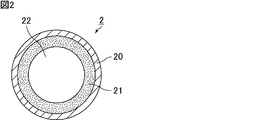
- FIG. 2 is a cross-sectional view schematically showing another example of a heat pipe manufactured by the heat pipe manufacturing method of the present invention.
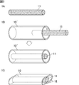
- FIG. 3 is a perspective view schematically showing an example of a heat pipe manufacturing method according to the first embodiment of the present invention.
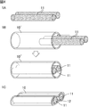
- FIG. 4 is a perspective view schematically showing another example of the heat pipe manufacturing method according to the first embodiment of the present invention.
- 5 (a), FIG. 5 (b), FIG. 5 (c), FIG. 5 (d), FIG. 5 (e) and FIG. 5 (f) show the manufacture of the heat pipe according to the first embodiment of the present invention.
- FIGS. 1 show typically another example of the heat pipe obtained by the method.
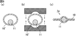
- 6 (a), 6 (b), and 6 (c) are cross-sectional views schematically showing an example of a method for manufacturing a heat pipe in which both side surfaces or one side surface of a container is flat.
- 7 (a), FIG. 7 (b), FIG. 7 (c1), FIG. 7 (c2), FIG. 7 (d1), and FIG. 7 (d2) are heat pipes having flat side surfaces or one side surface.
- 8 (a), 8 (b), 8 (c), and 8 (d) are cross-sectional views schematically showing still another example of a method for manufacturing a heat pipe in which one side surface of the container is flat. It is.
- FIG. 9A and 9B are cross-sectional views schematically showing still another example of the heat pipe obtained by the heat pipe manufacturing method according to the first embodiment of the present invention.
- FIG. 10 is a perspective view schematically showing an example of a heat pipe manufacturing method according to the second embodiment of the present invention.
- FIG. 11 is a perspective view schematically showing an example of a step of inserting a metal rod and metal powder.
- FIG. 12 is a perspective view schematically showing an example of a heat pipe manufacturing method according to the third embodiment of the present invention.
- FIG. 13 is a perspective view which shows typically an example of the manufacturing method of the heat pipe which concerns on 4th Embodiment of this invention.
- FIG. 14 is a perspective view schematically showing an example of a heat pipe manufacturing method according to the fifth embodiment of the present invention.
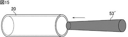
- FIG. 15 is a perspective view which shows typically another example of the manufacturing method of the heat pipe which concerns on 5th Embodiment of this invention.
- FIG. 16 is a perspective view which shows typically an example of the manufacturing method of the heat pipe which concerns on 6th Embodiment of this invention.
- the manufacturing method of the heat pipe of this invention is demonstrated.
- the present invention is not limited to the following configurations, and can be applied with appropriate modifications without departing from the scope of the present invention.
- the present invention also includes a combination of two or more desirable configurations of the present invention described below.
- FIG. 1 is a cross-sectional view schematically showing an example of a heat pipe manufactured by the heat pipe manufacturing method of the present invention.
- a heat pipe 1 shown in FIG. 1 includes a container 10 and a wick structure 11.
- the wick structure 11 is fixed to the central portion of the container 10, and a gap 12 is formed between the inner wall of the container 10 and the wick structure 11 at both ends of the container 10.
- the container 10 has a flat tube shape, but the cross-sectional shape of the container 10 is not particularly limited.
- a non-condensable gas such as air is degassed in the container 10, and a working fluid is sealed therein.
- FIG. 2 is a cross-sectional view schematically showing another example of a heat pipe manufactured by the heat pipe manufacturing method of the present invention.
- the heat pipe 2 shown in FIG. 2 includes a container 20 and a wick structure 21.
- the wick structure 21 is fixed to the inner wall of the container 20, and a gap 22 is formed in the central portion of the container 20.
- the container 20 has a tube shape with a substantially circular cross section, but the cross sectional shape of the container 20 is not particularly limited, and may have a flat tube shape.
- non-condensable gas such as air is degassed in the container 20, and the working fluid is sealed therein.
- the heat pipe 1 shown in FIG. 1 can be manufactured by the method according to the first embodiment of the present invention
- the heat pipe 2 shown in FIG. 2 is a method according to the second to sixth embodiments of the present invention. Can be manufactured by.
- FIG. 3 is a perspective view schematically showing an example of a heat pipe manufacturing method according to the first embodiment of the present invention.
- the rod-shaped wick structure 11 which consists of an intermetallic compound of a 1st metal and a 2nd metal is prepared.
- the wick structure is preferably produced by heating a metal powder containing a first metal and a second metal.
- a wick structure made of an intermetallic compound of a first metal and a second metal can be produced by filling the metal powder in a firing jig made of a heat-resistant ceramic such as alumina and heating. .
- a firing jig made of a heat-resistant ceramic such as alumina and heating.
- the wick structure can be produced by immersing a mesh made of a second metal into a rod shape, immersing it in the molten first metal, and heating it, or a porous rod made of the second metal. Can be produced by immersing in a molten first metal and heating it.
- the degree of porosity of the obtained sintered body can be adjusted, for example, pores having different sizes can be provided, compared to a method of heating metal powder containing the first metal and the second metal. Therefore, the performance of the heat pipe can be adjusted arbitrarily.
- pores are formed by the alloying reaction between the first metal and the second metal, whereas in the above method, the pores that are present from the beginning can be left in the mesh or porous rod made of the second metal. Therefore, if the size of the pores originally present in the mesh or porous rod made of the second metal is large, the first metal does not get wet at the center of the pores, so that the large pores remain as cavities, and further the alloying reaction As a result, small pores are newly formed.
- the ratio of the pores of different sizes can be adjusted depending on the temperature of the first metal to be melted, the immersion time, and the degree of porosity of the mesh or porous rod made of the second metal.
- the heating temperature is preferably 250 ° C. or higher and 350 ° C. or lower.
- the heating time is preferably 10 minutes or longer, more preferably 180 minutes or shorter, and more preferably 60 minutes or shorter.
- the first metal is Sn or Sn alloy, for example, Sn alone, Cu, Ni, Ag, Au, Sb, Zn, Bi, In, Ge, Al, Co, Mn, Fe, Cr, Mg, Mn
- Sn or Sn alloy for example, Sn alone, Cu, Ni, Ag, Au, Sb, Zn, Bi, In, Ge, Al, Co, Mn, Fe, Cr, Mg, Mn
- An alloy containing Sn and at least one selected from the group consisting of Pd, Si, Sr, Te, and P is given.
- Sn, Sn-3Ag-0.5Cu, Sn-3.5Ag, Sn-0.75Cu, Sn-58Bi, Sn-0.7Cu-0.05Ni, Sn-5Sb, Sn-2Ag-0.5Cu- 2Bi, Sn-57Bi-1Ag, Sn-3.5Ag-0.5Bi-8In, Sn-9Zn, or Sn-8Zn-3Bi is preferable.
- Sn-3Ag-0.5Cu indicates an alloy containing 3% by weight of Ag, 0.5% by weight of Cu, and the balance being Sn.
- the second metal is a Cu alloy, and examples thereof include a Cu—Ni alloy, a Cu—Mn alloy, a Cu—Al alloy, and a Cu—Cr alloy. Among these, a Cu—Ni alloy or a Cu—Mn alloy is preferable.
- the Cu—Ni alloy is preferably a Cu—Ni alloy with a Ni content of 5 wt% or more and 30 wt% or less, for example, Cu-5Ni, Cu-10Ni, Cu-15Ni, Cu-20Ni, Cu-25Ni, or Cu-30Ni.
- the Cu—Ni alloy includes alloys containing a third component such as a Cu—Ni—Co alloy and a Cu—Ni—Fe alloy.
- the Cu—Mn alloy is preferably a Cu—Mn alloy having a Mn ratio of 5 wt% or more and 30 wt% or less, such as Cu-5Mn, Cu-10Mn, Cu-15Mn, Cu-20Mn, Cu-25Mn, or Cu-30Mn.
- the Cu—Al alloy is preferably a Cu—Al alloy having an Al ratio of 5% by weight or more and 10% by weight or less, and examples thereof include Cu-5Al and Cu-10Al.
- the Cu—Cr alloy is preferably a Cu—Cr alloy having a Cr ratio of 5 wt% or more and 10 wt% or less, and examples thereof include Cu-5Cr and Cu-10Cr.
- the second metal may contain Mn and Ni at the same time, such as Cu—Mn—Ni, or may contain a third component such as P.
- Mn and Ni at the same time, such as Cu—Mn—Ni, or may contain a third component such as P.
- Cu-5Ni indicates an alloy containing 5% by weight of Ni and the balance being Cu. The same applies to Mn, Al or Cr.
- the metal powder containing the first metal and the second metal is heated so that the temperature reaches or exceeds the melting point of the first metal (for example, Sn), the first metal is melted.
- the first metal and the second metal for example, Cu—Ni alloy
- react to generate an intermetallic compound for example, (Cu, Ni) 6 Sn 5 ).
- the intermetallic compound As the intermetallic compound is generated, voids (pores) are formed in the intermetallic compound, so that the intermetallic compound is porous. From the viewpoint of making the intermetallic compound porous, it is preferable to react both in a state where the first metal and the second metal are not pressurized.
- the intermetallic compound in the wick structure can be easily confirmed by observing the cross section of the wick structure using a metal microscope. Specifically, intermetallic compounds such as (Cu, Ni) 6 Sn 5 are confirmed by performing composition analysis by energy dispersive X-ray analysis (EDX) and the like and crystal structure analysis by microscopic X-ray diffraction and the like. can do.
- EDX energy dispersive X-ray analysis
- the shape of the wick structure is not particularly limited as long as it is rod-shaped, but is preferably cylindrical.
- the shape of the wick structure may be a truncated cone shape.
- the length of the wick structure is not particularly limited.
- the wick structure 11 is inserted in tubular container 10 '.
- one wick structure 11 is inserted, but two or more wick structures may be inserted.
- the container is preferably made of a material having high thermal conductivity because heat needs to be transferred inside and outside.
- a material for the container for example, a metal such as copper or aluminum can be used.
- heat pipes need to have heat resistance and mechanical strength that can withstand internal vapor pressure and external force, for example, stainless steel, copper alloy, carbon steel, etc. may be used as the container material. it can.
- the shape of the container is not particularly limited, and may be a cylinder other than a cylinder. Further, the shape of the inner wall of the container is not particularly limited, and a capillary structure such as a groove may be provided on the inner wall.
- Examples of the method for deforming the container include rolling methods such as hot rolling and cold rolling, and processing methods such as bending. Since the intermetallic compound constituting the wick structure is a brittle member, the above processing is preferably performed within a range in which the container can be deformed.
- the wick structure can be brought into contact with the inner wall of the container, and the wick structure is fixed in the container by an anchor effect.
- the intermetallic compound constituting the wick structure is porous, the working fluid can be moved by capillary action.
- the gap between the container inner wall and the wick structure functions as a steam flow path.
- non-condensable gas such as air existing inside the container is degassed, and the working liquid is sealed in the container.
- the hydraulic fluid water, ethanol, methanol, naphthalene, benzene, alternative chlorofluorocarbon, ammonia or the like can be used.
- a vacuum degassing method or a method of injecting an excess amount of hydraulic fluid in advance and driving out the non-condensable gas by boiling the hydraulic fluid by heating the container Etc. are used for degassing non-condensable gas.
- the heat pipe 1 shown in FIG. 1 can be manufactured.
- FIG. 4 is a perspective view schematically showing another example of the heat pipe manufacturing method according to the first embodiment of the present invention.
- 1A of FIG. 4 unlike 1A of FIG. 3, two rod-like wick structures 11 are prepared.
- 1B of FIG. 4 after inserting the two wick structures 11 in the tubular container 10 ', the container 10' is deformed.
- the two wick structures 11 are fixed in the container 10 in the state which left the space
- two or more wick structures may be inserted into the container.
- Both side surfaces of the container 10 may be flat like a heat pipe 1a shown in FIG. 5 (a), a heat pipe 1b shown in FIG. 5 (b), and a heat pipe 1c shown in FIG. 5 (c).
- the side surface of the container 10 is flat like the heat pipe 1d shown in FIG. 5 (d), the heat pipe 1e shown in FIG. 5 (e), and the heat pipe 1f shown in FIG. 5 (f). Also good.
- a heat pipe in which both side surfaces or one side surfaces of the container are flat can be manufactured, for example, by the method described below.
- a container can be made into arbitrary shapes, such as not only the shape where the both sides
- FIG. 6A after the wick structure 11 is inserted into the tubular container 10 ′, the container 10 ′ is pressed as shown in FIG. 6B. Thereby, as shown in FIG.6 (c), the shape of the heat pipe 1a shown to Fig.5 (a) is obtained, for example.
- FIG. 7 (a), FIG. 7 (b), FIG. 7 (c1), FIG. 7 (c2), FIG. 7 (d1), and FIG. 7 (d2) are heat pipes having flat side surfaces or one side surface. It is sectional drawing which shows typically another example of this manufacturing method.
- a plate-like (including foil-like) container 10 ′′ is molded.
- FIG. 7C1 after the wick structure 11 is inserted so as to be accommodated in the two molded containers 10 ′′, the end of the container 10 ′′ is welded or the like.
- FIG. 7 (d1) for example, the shape of the heat pipe 1a shown in FIG. 5 (a) is obtained. Further, as shown in FIG.
- FIGS. 8A and 8B are cross-sectional views schematically showing still another example of a method for manufacturing a heat pipe in which one side surface of the container is flat. It is.
- a plate-like (including foil-like) container 10 ′′ is molded.
- FIG. 8C after the wick structure 11 is inserted so as to be accommodated in one molded container 10 ′′, the end of the container 10 ′′ is sealed by welding or the like. By doing so, as shown in FIG. 8D, for example, the shape of the heat pipe 1d shown in FIG. 5D is obtained.
- a method of enclosing the working fluid in the container for example, a method of impregnating the wick structure in advance before inserting the wick structure
- three ways Examples include a method of injecting a working fluid from an unsealed port after sealing and finally sealing all sides.
- FIGS. 9A and 9B are cross-sectional views schematically showing still another example of the heat pipe obtained by the heat pipe manufacturing method according to the first embodiment of the present invention.
- the cross-sectional shape of the wick structure 11a is semicircular
- the cross-sectional shape of the wick structure 11b is rectangular.
- the shape of the container 10 is the same as in FIG. 1, but FIGS. 5 (a), 5 (b), 5 (c), 5 (d), It may be the same as FIG. 5 (e), FIG. 5 (f) and the like.
- the shape of the wick structure is not limited to a columnar shape or a truncated cone shape, and may be a semi-columnar shape, a rectangular column shape (preferably a rectangular parallelepiped shape), a hexagonal column shape, or the like. Also good.
- a wick structure having a shape such as a semi-cylindrical shape or a prism shape is suitably used for a thin heat pipe.
- the wick structure having a predetermined shape is arranged, for example, by placing the metal powder so as to have a desired shape when filling a firing jig with metal powder containing a first metal and a second metal. Can be produced by heating.
- the wick structure has a curved surface, such as a columnar shape or a semi-cylindrical shape, the contact area with the firing jig can be reduced, so that the wick structure can be easily taken out from the firing jig. is there.
- the wick structure has a flat surface, such as a prismatic shape
- the wick structure when the wick structure is inserted into the container, the wick structure can be transported while holding the flat surface such as the side surface. Then, there is an advantage that it can be conveyed.
- a heat pipe having an arbitrary shape can be manufactured by preparing a wick structure having a predetermined shape in advance and deforming the container into the predetermined shape.
- FIG. 10 is a perspective view schematically showing an example of a heat pipe manufacturing method according to the second embodiment of the present invention.
- a metal rod 23 made of a first metal is prepared.
- a 1st metal is Sn or Sn alloy, and what was demonstrated in 1st Embodiment is mentioned.
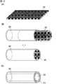
- the shape of the metal rod is preferably a hollow tube as shown in 2A of FIG.
- what rolled the foil for example, Sn foil
- the metal rod is a hollow tube, at least one end face may be sealed.
- the length of the metal rod is not particularly limited.
- the metal rod 23 and the metal powder 24 are inserted into the tubular container 20. At this time, the metal rod 23 and the metal powder 24 are inserted into the container 20 so that the space between the inner wall of the container 20 and the metal rod 23 is filled with the metal powder 24.
- the metal rod 23 is a hollow tube, it is preferable to fill the metal powder 24 so that the metal powder 24 does not enter the hollow portion.
- the material, shape, and the like of the container 20 are the same as those of the container 10 ′ described in the first embodiment.
- the metal powder includes a second metal.
- the second metal is a Cu alloy, and those described in the first embodiment can be mentioned.
- the content of the second metal in the metal powder is preferably 60% by weight or more, more preferably 80% by weight or more, and particularly preferably 100% by weight.
- FIG. 11 is a perspective view schematically showing an example of a step of inserting a metal rod and metal powder.
- 2B-1 of FIG. 11 after inserting the metal rod 23 into the container 20, the space between the inner wall of the container 20 and the metal rod 23 is filled with the metal powder 24.
- the metal rod 23 is a hollow tube, it is preferable that at least the end surface on the side where the metal powder is inserted is sealed so that the metal powder 24 does not enter the hollow portion.
- the metal rod 23 is inserted into the container 20 so as to push out the metal powder 24 in the container 20.
- the metal rod 23 is a hollow tube
- at least the end surface on the side where the metal rod is inserted is sealed so that the metal powder 24 does not enter the hollow portion.
- the metal rod 23 to which the metal powder 24 is attached is inserted into the container 20.
- at least one end surface may be sealed.
- a method of attaching metal powder around the metal rod a method of applying a paste containing metal powder around the metal rod, a method of plating metal particles on the metal rod, a method of spraying metal powder onto the metal rod, etc. Is mentioned.
- the metal powder may be further filled, or the metal powder may be filled. The metal bar may be inserted into the sealed container.
- the metal rod and metal powder inserted into the container are heated.
- the first metal constituting the metal rod reacts with the second metal contained in the metal powder to produce an intermetallic compound, and the metal rod disappears.
- a wick structure 21 made of an intermetallic compound is formed, and a void 22 is formed in the container 20.
- the wick structure made of the intermetallic compound is fixed in the container.
- the heating temperature is preferably a temperature equal to or higher than the melting point of the first metal, and specifically, 250 ° C. or higher and 350 ° C. or lower is preferable.
- the heating time is preferably 10 minutes or longer, more preferably 180 minutes or shorter, and more preferably 60 minutes or shorter.
- the reaction between the first metal and the second metal is as described in the first embodiment.
- the intermetallic compound constituting the wick structure is porous, the working fluid can be moved by capillary action.
- the void in the container functions as a steam flow path.
- non-condensable gas such as air existing inside the container is degassed, and the working fluid is sealed in the container.
- the container may be flattened or bent before the working fluid is sealed in the container or after the working fluid is sealed in the container.
- the heat pipe 2 shown in FIG. 2 can be manufactured.
- FIG. 12 is a perspective view schematically showing an example of a heat pipe manufacturing method according to the third embodiment of the present invention.
- the mesh sheet 35 containing a 1st metal and a 2nd metal is prepared.
- a 1st metal is Sn or Sn alloy, and what was demonstrated in 1st Embodiment is mentioned.
- the second metal is a Cu alloy, and those described in the first embodiment can be mentioned.
- Examples of the mesh shape of the mesh sheet include a woven mesh shape, a knitted mesh shape, and a mesh shape in which fine holes are punched at a predetermined interval.
- the mesh sheet is preferably produced by plating the first metal on a mesh made of the second metal.
- seat by making the metal powder containing a 1st metal adhere to the mesh which consists of a 2nd metal.
- metal powder may be attached to at least one main surface of the mesh.
- the metal powder attached to the mesh preferably contains a second metal in addition to the first metal.
- the second metal contained in the metal powder may be different from the second metal constituting the mesh, but is preferably the same as the second metal constituting the mesh.
- the content of the first metal in the metal powder is preferably 40% by weight or more and 80% by weight or less. Further, the content of the second metal in the metal powder is preferably 20% by weight or more and 60% by weight or less.
- the metal powder can be attached to the mesh by filling the mesh with metal powder, applying a paste containing the metal powder to the mesh, plating the metal particles onto the mesh, and spraying the metal powder onto the mesh. And the like.
- the particle size of the metal powder attached to the mesh is preferably larger than the mesh size of the mesh.
- the particle size of the metal powder is the same as or smaller than the mesh mesh size, the mesh mesh is filled with the metal powder, and the wick structure formed after the reaction may become dense.
- the mesh sheet 35 is inserted into the tubular container 20.
- the core sheet is not used, the mesh sheet 35 is rolled, and the mesh sheet 35 is inserted into the container 20 along the inner wall of the container 20.
- one mesh sheet 35 is inserted, but two or more mesh sheets may be inserted.
- the mesh sheet inserted into the container may overlap two or more layers.
- the material, shape, and the like of the container 20 are the same as those of the container 10 ′ described in the first embodiment.
- the mesh sheet inserted into the container is heated.
- the 1st metal and 2nd metal which comprise a mesh sheet react, and an intermetallic compound produces
- a wick structure 21 made of an intermetallic compound is formed.
- a gap 22 is formed in the container 20.
- the heating temperature is preferably a temperature equal to or higher than the melting point of the first metal, and specifically, 250 ° C. or higher and 350 ° C. or lower is preferable.
- the heating time is preferably 10 minutes or longer, more preferably 180 minutes or shorter, and more preferably 60 minutes or shorter.
- the reaction between the first metal and the second metal is as described in the first embodiment.
- the intermetallic compound constituting the wick structure is porous, the working fluid can be moved by capillary action.
- the void in the container functions as a steam flow path.
- non-condensable gas such as air existing inside the container is degassed, and the working fluid is sealed in the container.
- the container may be flattened or bent before the working fluid is sealed in the container or after the working fluid is sealed in the container. Moreover, after inserting a mesh sheet in a container, you may give the said process before heating a mesh sheet.
- the heat pipe 2 shown in FIG. 2 can be manufactured.
- FIG. 13 is a perspective view which shows typically an example of the manufacturing method of the heat pipe which concerns on 4th Embodiment of this invention.
- a core rod 46 with a mesh in which a mesh 45 made of a second metal is wound around the core rod 43 is prepared.
- one mesh sheet 45 is wound, but two or more mesh sheets may be wound.
- the mesh sheet wound around the core rod may overlap two or more layers.
- the second metal is a Cu alloy, and those described in the first embodiment can be mentioned. Moreover, what was demonstrated in 3rd Embodiment is mentioned as a mesh shape of a mesh sheet.
- the core rod material has a melting point higher than the temperature at which the first metal and the second metal react to produce an intermetallic compound, and the first metal and the second metal at the temperature at which the intermetallic compound is produced. Those that do not react with metals are preferred.
- a material for the core rod for example, stainless steel, alumina or the like can be used.
- the shape of the core rod is not particularly limited, but is preferably a cylindrical shape.
- the core rod may have a cutout portion along the long axis direction, or may have a shape that can be divided. Further, the shape of the core rod may be a truncated cone shape.
- the length of the core rod is not particularly limited, but is preferably the same as the container length or longer than the container.
- the meshed core rod 46 and the metal powder 44 are inserted into the tubular container 20.
- the mesh core rod 46 and the metal powder 44 are inserted into the container 20 so that the space between the inner wall of the container 20 and the mesh core rod 46 is filled with the metal powder 44.
- the material, shape, and the like of the container 20 are the same as those of the container 10 ′ described in the first embodiment.
- the metal powder includes a first metal and a second metal.
- a 1st metal is Sn or Sn alloy, and what was demonstrated in 1st Embodiment is mentioned.
- the second metal contained in the metal powder may be different from the second metal constituting the mesh, but is preferably the same as the second metal constituting the mesh.
- the content of the first metal in the metal powder is preferably 20% by weight or more and 60% by weight or less.
- the content of the second metal in the metal powder is preferably 40% by weight or more and 80% by weight or less.
- the same method as in the second embodiment that is, after inserting the core rod with mesh into the container, the inner wall of the container and the core rod with mesh is inserted.
- Method of filling the space between the metal powder, filling the container with metal powder, then inserting the core rod with mesh into the container to extrude the metal powder in the container, metal to the mesh of the core rod with mesh Examples include a method of inserting a core rod with a mesh to which a metal powder is adhered into a container after the powder is adhered.
- the metal powder may be further filled, or the container with the mesh is filled with the metal powder.
- a core rod may be inserted.
- the core rod with mesh and metal powder inserted in the container are heated.
- the first metal and the second metal contained in the metal powder react with each other, and the first metal contained in the metal powder reacts with the second metal constituting the meshed core rod to form an intermetallic compound.
- a wick structure 21 made of an intermetallic compound is formed.
- the wick structure made of the intermetallic compound is fixed in the container. Since the mesh made of the second metal is wound around the core rod, when the first metal and the second metal react between the inner wall of the container and the core rod, the molten first metal is applied to the core rod.
- the heating temperature is preferably a temperature equal to or higher than the melting point of the first metal, and specifically, 250 ° C. or higher and 350 ° C. or lower is preferable.
- the heating time is preferably 10 minutes or longer, more preferably 180 minutes or shorter, and more preferably 60 minutes or shorter.
- the reaction between the first metal and the second metal is as described in the first embodiment.
- the intermetallic compound constituting the wick structure is porous, the working fluid can be moved by capillary action.
- the core rod 43 is pulled out from the container 20.
- a gap 22 is formed in the container 20.
- the void in the container functions as a steam flow path.
- the mesh wound around the core rod reacts with the first metal to form an intermetallic compound, it is fixed to the container. As a result, only the core rod can be pulled out from the container.
- non-condensable gas such as air existing inside the container is degassed, and the working fluid is sealed in the container.
- the container may be flattened or bent before the working fluid is sealed in the container or after the working fluid is sealed in the container.
- the heat pipe 2 shown in FIG. 2 can be manufactured.
- FIG. 14 is a perspective view schematically showing an example of a heat pipe manufacturing method according to the fifth embodiment of the present invention.
- the core rod 53 which consists of resin is prepared.
- 14A shows a core rod 53 made entirely of resin, it may be a core rod made of resin at least on the surface. Further, in FIG. 14A, a cylindrical core rod is shown, but the core rod may be a round bar having a taper at least at one end. Furthermore, in FIG. 14A, a round bar-shaped core rod is shown, but a hollow round bar-shaped core rod may be used.
- the resin has a melting point higher than the temperature at which the first metal and the second metal react to form an intermetallic compound, and has a thermal expansion coefficient larger than the thermal expansion coefficient of the intermetallic compound.
- the melting point of the resin means a value measured according to differential scanning calorimetry (DSC) in JIS K7121.
- DSC differential scanning calorimetry
- the resin does not react with the first metal and the second metal at a temperature at which the intermetallic compound is generated.
- the resin material examples include silicone resin, polybenzimidazole resin (PBI), polyether ether ketone resin (PEEK), polyimide resin (PI), polyamideimide resin (PAI), and polytetrafluoroethylene resin (PTFE). And perfluoroalkoxy resin (PFA).
- a silicone resin is preferable.
- the core rod includes a material other than resin
- examples of the material other than resin include those described in the fourth embodiment.
- the shape, length, etc. of a core rod are the same as the core rod demonstrated in 4th Embodiment.
- the core rod 53 and the metal powder 54 are inserted into the tubular container 20.
- the core rod 53 and the metal powder 54 are inserted into the container 20 so that the space between the inner wall of the container 20 and the core rod 53 is filled with the metal powder 54.
- the material, shape, and the like of the container 20 are the same as those of the container 10 ′ described in the first embodiment.
- the metal powder includes a first metal and a second metal.
- a 1st metal is Sn or Sn alloy, and what was demonstrated in 1st Embodiment is mentioned.
- the second metal is a Cu alloy, and those described in the first embodiment can be mentioned.
- the content of the first metal in the metal powder is preferably 20% by weight or more and 40% by weight or less. Further, the content of the second metal in the metal powder is preferably 60% by weight or more and 80% by weight or less.
- the same method as in the second embodiment that is, after inserting the core rod into the container, the metal powder is inserted into the space between the inner wall of the container and the core rod.
- the metal powder is inserted into the space between the inner wall of the container and the core rod.
- the metal powder is for example, a method of inserting the attached core rod into the container may be used.
- the metal powder may be further filled, or the core rod is inserted into the container filled with metal powder. Also good.
- the core rod and metal powder inserted into the container are heated.
- the 1st metal and 2nd metal which are contained in metal powder react, and an intermetallic compound produces
- the resin constituting the core rod 53 expands during heating, the wick structure 21 made of an intermetallic compound is formed while being pressed against the expanded resin.
- the resin shrinks during cooling after heating a gap 52 is generated between the wick structure 21 and the core bar 53.
- the wick structure made of the intermetallic compound is fixed in the container.
- the heating temperature is preferably a temperature equal to or higher than the melting point of the first metal, and specifically, 250 ° C. or higher and 300 ° C. or lower is preferable.
- the heating time is preferably 10 minutes or longer, more preferably 180 minutes or shorter, and more preferably 60 minutes or shorter.
- the reaction between the first metal and the second metal is as described in the first embodiment.
- the intermetallic compound constituting the wick structure is porous, the working fluid can be moved by capillary action.
- the core rod 53 is pulled out from the container 20.
- a gap 22 is formed in the container 20.
- the void in the container functions as a steam flow path.
- the core rod can be easily pulled out from the container.
- non-condensable gas such as air existing inside the container is degassed, and the working fluid is sealed in the container.
- the container may be flattened or bent before the working fluid is sealed in the container or after the working fluid is sealed in the container.
- the heat pipe 2 shown in FIG. 2 can be manufactured.
- FIG. 15 is a perspective view which shows typically another example of the manufacturing method of the heat pipe which concerns on 5th Embodiment of this invention.
- a truncated cone-shaped core rod 53 ′ having a tapered tip is prepared.
- it is preferable that at least one tip of the core rod is tapered. From the viewpoint of ease of pulling out the core rod, it is preferable to insert the tapered portion of the core rod 53 ′ into the container 20 as shown in FIG. 15.
- FIG. 16 is a perspective view which shows typically an example of the manufacturing method of the heat pipe which concerns on 6th Embodiment of this invention.
- the core bar 63 and the metal powder 64 are inserted in the tubular container 20. As shown in FIG. At this time, the core rod 63 and the metal powder 64 are inserted into the container 20 so that the space between the inner wall of the container 20 and the core rod 63 is filled with the metal powder 64.
- the material, shape, and the like of the container 20 are the same as those of the container 10 ′ described in the first embodiment.
- the core rod examples include those described in the fourth embodiment.
- the core rod is preferably made of a heating element.
- a ceramic tube with a built-in heat wire is preferably used as the core rod, and an alumina tube with a built-in nichrome wire is more preferably used as the core rod.
- the shape, length, etc. of a core rod are the same as the core rod demonstrated in 4th Embodiment.
- the metal powder includes a first metal and a second metal.
- a 1st metal is Sn or Sn alloy, and what was demonstrated in 1st Embodiment is mentioned.
- the second metal is a Cu alloy, and those described in the first embodiment can be mentioned.
- the content of the first metal in the metal powder is preferably 20% by weight or more and 40% by weight or less. Further, the content of the second metal in the metal powder is preferably 60% by weight or more and 80% by weight or less.
- the same method as in the second embodiment that is, after inserting the core rod into the container, the metal powder is inserted into the space between the inner wall of the container and the core rod.
- the metal powder is inserted into the space between the inner wall of the container and the core rod.
- the metal powder is for example, a method of inserting the attached core rod into the container may be used.
- the metal powder may be further filled, or the core rod is inserted into the container filled with metal powder. Also good.
- the metal powder in the container in which the core rod is inserted is heated at a temperature lower than the melting point of the first metal.
- a part of the first metal and a part of the second metal contained in the metal powder 64 react, and a part of the metal powder 64 becomes the intermetallic compound 61.
- the shape of the metal powder 64 is maintained, and the metal powder 64 is fixed in the container 20.
- the entire container may be heated, but it is preferable to heat the metal powder by heating the core rod.
- the core rod By causing the core rod to generate heat, the metal powder at the portion in contact with the core rod can be made into an intermetallic compound.
- the heating temperature is not particularly limited as long as it is lower than the melting point of the first metal, but is preferably 170 ° C. or higher and 230 ° C. or lower, and more preferably 200 ° C. or higher and 230 ° C. or lower.
- the heating time is preferably 15 minutes or more and 180 minutes or less.
- the core rod 63 is pulled out from the container 20 as shown in 6C of FIG. As a result, a gap 22 is formed in the container 20. As described above, since the shape of the metal powder is maintained and the metal powder is fixed in the container, the core rod can be pulled out from the container.
- the metal powder in the container in which the core bar is pulled out is heated at a temperature equal to or higher than the melting point of the first metal.
- the unreacted first metal and the second metal contained in the metal powder react to generate an intermetallic compound.
- a wick structure 21 made of an intermetallic compound is formed.
- the wick structure made of the intermetallic compound is fixed in the container.
- the step of heating the metal powder at a temperature equal to or higher than the melting point of the first metal it is preferable to heat the entire container.
- the heating temperature is not particularly limited as long as it is a temperature equal to or higher than the melting point of the first metal, but is preferably 250 ° C or higher and 350 ° C or lower.
- the heating time is preferably 10 minutes or longer, more preferably 180 minutes or shorter, and more preferably 60 minutes or shorter.
- the reaction between the first metal and the second metal is as described in the first embodiment.
- the intermetallic compound constituting the wick structure is porous, the working fluid can be moved by capillary action.
- the void in the container functions as a steam flow path.
- non-condensable gas such as air existing inside the container is degassed, and the working fluid is sealed in the container.
- the container may be flattened or bent before the working fluid is sealed in the container or after the working fluid is sealed in the container.
- the heat pipe 2 shown in FIG. 2 can be manufactured.
- the configurations shown in the different embodiments can be partially replaced or combined.
- the core rod described in the fifth embodiment may be used in the fourth embodiment and the sixth embodiment, or the method described in the sixth embodiment is combined with the fourth embodiment and the fifth embodiment. Also good.
Landscapes
- Engineering & Computer Science (AREA)
- Mechanical Engineering (AREA)
- Thermal Sciences (AREA)
- Physics & Mathematics (AREA)
- Life Sciences & Earth Sciences (AREA)
- Manufacturing & Machinery (AREA)
- Sustainable Development (AREA)
- General Engineering & Computer Science (AREA)
- Composite Materials (AREA)
- Materials Engineering (AREA)
- Chemical & Material Sciences (AREA)
- Microelectronics & Electronic Packaging (AREA)
- Cooling Or The Like Of Semiconductors Or Solid State Devices (AREA)
- Powder Metallurgy (AREA)
Abstract
本発明のヒートパイプの製造方法は、第1金属であるSn又はSn合金と第2金属であるCu合金との金属間化合物からなる、棒状のウィック構造体を準備する工程と、管状のコンテナ内に上記ウィック構造体を挿入する工程と、上記コンテナを変形させることにより、上記コンテナの内壁と上記ウィック構造体との間に空隙を残した状態で、上記コンテナ内に上記ウィック構造体を固定する工程と、を備えることを特徴とする。
Description
本発明は、ヒートパイプの製造方法に関する。
ヒートパイプは、パソコン等の電子機器に搭載されるCPUの冷却等に使用される。ヒートパイプは、非凝縮性流体を脱気して、適量の作動液が封入されている密閉された金属体である。コンテナ内部に封入された作動液は、蒸発部においてコンテナ外部から加熱されることで蒸発し、凝縮部において蒸気が冷却されることで凝縮して作動液に戻り、潜熱として熱を輸送する。潜熱として熱を輸送するため、蒸発部と凝縮部の小さな温度差でも熱を輸送することが可能となる。
コンテナ内では、凝縮部で凝縮した作動液を蒸発部に還流させる必要がある。蒸発部が凝縮部より上側に位置する場合や、蒸発部及び凝縮部が水平に位置する場合には、作動液の還流に作動液の表面張力を利用する。そのため、コンテナ内部にウィック構造体を必要とする。
ウィック構造体には、多数本の細線を束ねた線状体、メッシュ等の網目体、銅粉等の金属粉末を焼結した焼結体が用いられる。金属粉末の焼結体を利用したものは、高い表面張力を得られることが知られている。
例えば、特許文献1には、切り欠き部を有する芯棒をコンテナ内に挿入し、芯棒の切り欠き部とコンテナの内壁とで形成される空間に金属粉末を充填し、金属粉末及び芯棒が挿入された状態でコンテナを加熱し、コンテナから芯棒を引き抜き、コンテナに扁平加工を施し、コンテナ内に作動液を封入するヒートパイプの製造方法が開示されている。
特許文献1に記載の方法では、金属粉末及び芯棒が挿入された状態でコンテナを加熱することで、金属粉末が焼結して焼結金属を形成し、この焼結金属をコンテナに固定することができる。しかし、加熱により焼結金属をコンテナに固定する際、芯棒と焼結金属とが固着してしまい、芯棒の引き抜きが困難になるという問題がある。
コンテナから芯棒が容易に引き抜けなくなると、ヒートパイプを製造するための時間が長くなるため、ヒートパイプの生産性が低下するという問題が生じる。
本発明は上記の問題を解決するためになされたものであり、コンテナから芯棒を引き抜く必要がないヒートパイプの製造方法、又は、コンテナから芯棒を容易に引き抜くことができるヒートパイプの製造方法を提供することを目的とする。
本発明者らは、第1金属であるSn又はSn合金と、第1金属よりも融点の高い第2金属であるCu合金との金属間化合物をウィック構造体として使用することを考えた。第1金属(例えばSn)と第2金属(例えばCu-Ni合金)とを加熱した場合、温度が第1金属の融点以上に達すると、第1金属が溶融する。さらに加熱が続くと、第1金属と第2金属とが反応し、金属間化合物(例えば(Cu,Ni)6Sn5)が生成する。金属間化合部が形成される際にはボイド(気孔)が生じるため、上記金属間化合物は、ウィック構造体に適した多孔質となる。
本発明の第1実施形態に係るヒートパイプの製造方法は、第1金属であるSn又はSn合金と第2金属であるCu合金との金属間化合物からなる、棒状のウィック構造体を準備する工程と、管状のコンテナ内に上記ウィック構造体を挿入する工程と、上記コンテナを変形させることにより、上記コンテナの内壁と上記ウィック構造体との間に空隙を残した状態で、上記コンテナ内に上記ウィック構造体を固定する工程と、を備えることを特徴とする。
本発明の第1実施形態では、棒状のウィック構造体を準備しておき、これを管状のコンテナ内に挿入して固定することによって、コンテナから芯棒を引き抜くことなくヒートパイプを製造することができる。
本発明の第1実施形態において、上記ウィック構造体を準備する工程では、上記第1金属と上記第2金属とを含む金属粉末を加熱することにより上記ウィック構造体を作製することが好ましい。
例えば、ウィック構造体として銅粉の焼結体を作製する場合には、900℃程度の高温で焼結を行う必要があるため、コンテナ内に挿入する前にウィック構造体を別途作製することは行われていなかった。これに対し、第1金属と第2金属との金属間化合物からなるウィック構造体を作製する場合には、300℃程度の低温で加熱を行えばよいため、ウィック構造体を容易に作製することができる。
例えば、ウィック構造体として銅粉の焼結体を作製する場合には、900℃程度の高温で焼結を行う必要があるため、コンテナ内に挿入する前にウィック構造体を別途作製することは行われていなかった。これに対し、第1金属と第2金属との金属間化合物からなるウィック構造体を作製する場合には、300℃程度の低温で加熱を行えばよいため、ウィック構造体を容易に作製することができる。
本発明の第2実施形態に係るヒートパイプの製造方法は、第1金属であるSn又はSn合金からなる金属棒を準備する工程と、管状のコンテナの内壁と上記金属棒との間の空間に、第2金属であるCu合金を含む金属粉末が充填されるように、上記金属棒及び上記金属粉末を上記コンテナ内に挿入する工程と、上記コンテナ内に挿入された上記金属棒及び上記金属粉末を加熱することにより、上記金属棒を構成する上記第1金属と上記金属粉末に含まれる上記第2金属とを反応させて、金属間化合物からなるウィック構造体を形成するとともに、上記コンテナ内に空隙を形成する工程と、を備えることを特徴とする。
本発明の第2実施形態では、従来使用されていた芯棒に代えて、第1金属からなる金属棒を使用し、この金属棒と第2金属を含む金属粉末とをコンテナ内に挿入する。コンテナ内に挿入された金属棒及び金属粉末を加熱することにより、金属棒を構成する第1金属と金属粉末に含まれる第2金属とが反応して、金属間化合物からなるウィック構造体が形成されるとともに、金属棒が消滅するため、コンテナ内に空隙が形成される。したがって、コンテナから芯棒を引き抜くことなくヒートパイプを製造することができる。
本発明の第2実施形態において、上記金属棒及び上記金属粉末を挿入する工程では、上記コンテナ内に上記金属棒を挿入した後、上記コンテナの内壁と上記金属棒との間の空間に上記金属粉末を充填してもよい。また、上記金属棒及び上記金属粉末を挿入する工程では、上記コンテナ内に上記金属粉末を充填した後、上記コンテナ内の上記金属粉末を押し出すように上記コンテナ内に上記金属棒を挿入してもよい。さらに、上記金属棒及び上記金属粉末を挿入する工程では、上記金属棒の周囲に上記金属粉末を付着させた後、上記金属粉末が付着した上記金属棒を上記コンテナ内に挿入してもよい。
本発明の第3実施形態に係るヒートパイプの製造方法は、第1金属であるSn又はSn合金と第2金属であるCu合金とを含むメッシュシートを準備する工程と、管状のコンテナの内壁に沿うように、上記メッシュシートを上記コンテナ内に挿入する工程と、上記コンテナ内に挿入された上記メッシュシートを加熱することにより、上記メッシュシートを構成する上記第1金属と上記第2金属とを反応させて、金属間化合物からなるウィック構造体を形成する工程と、を備えることを特徴とする。
本発明の第3実施形態では、第1金属と第2金属とを含むメッシュシートを、コンテナの内壁に沿うようにコンテナ内に挿入する。コンテナ内に挿入されたメッシュシートを加熱することにより、メッシュシートを構成する第1金属と第2金属とが反応して、金属間化合物からなるウィック構造体が形成される。したがって、コンテナから芯棒を引き抜くことなくヒートパイプを製造することができる。
本発明の第3実施形態において、上記メッシュシートを準備する工程では、上記第2金属からなるメッシュに上記第1金属をめっきすることにより上記メッシュシートを作製することが好ましい。また、上記メッシュシートを準備する工程では、上記第2金属からなるメッシュに上記第1金属を含む金属粉末を付着させることにより上記メッシュシートを作製することが好ましい。
第2金属からなるメッシュを用いることにより、第1金属と反応させた後に形成されるウィック構造体の気孔率を高くすることができる。金属粉末をメッシュに付着させる場合、ウィック構造体の気孔率をさらに高くすることができる。
第2金属からなるメッシュを用いることにより、第1金属と反応させた後に形成されるウィック構造体の気孔率を高くすることができる。金属粉末をメッシュに付着させる場合、ウィック構造体の気孔率をさらに高くすることができる。
本発明の第4実施形態に係るヒートパイプの製造方法は、第2金属であるCu合金からなるメッシュが芯棒の周囲に巻き付けられたメッシュ付き芯棒を準備する工程と、管状のコンテナの内壁と上記メッシュ付き芯棒との間の空間に、第1金属であるSn又はSn合金と上記第2金属とを含む金属粉末が充填されるように、上記メッシュ付き芯棒及び上記金属粉末を上記コンテナ内に挿入する工程と、上記コンテナ内に挿入された上記メッシュ付き芯棒及び上記金属粉末を加熱することにより、上記金属粉末に含まれる上記第1金属と上記第2金属とを反応させるとともに、上記金属粉末に含まれる上記第1金属と上記メッシュ付き芯棒を構成する上記第2金属とを反応させて、金属間化合物からなるウィック構造体を形成する工程と、上記コンテナから上記芯棒を引き抜く工程と、を備えることを特徴とする。
本発明の第4実施形態では、第2金属からなるメッシュが芯棒の周囲に巻き付けられているため、コンテナの内壁と芯棒との間で第1金属と第2金属とが反応した際、溶融した第1金属が芯棒に接触しにくくなり、芯棒と金属間化合物との固着が防止される。一方、芯棒の周囲に巻き付けられていたメッシュは、第1金属と反応して金属間化合物を形成するため、コンテナに固定される。その結果、コンテナから芯棒のみを引き抜くことができる。
本発明の第5実施形態に係るヒートパイプの製造方法は、少なくとも表面が樹脂からなり、上記樹脂は、第1金属であるSn又はSn合金と第2金属であるCu合金とが反応して金属間化合物が生成する温度よりも高い融点を有し、かつ、上記金属間化合物の熱膨張係数よりも大きい熱膨張係数を有する芯棒を準備する工程と、管状のコンテナの内壁と上記芯棒との間の空間に、上記第1金属と上記第2金属とを含む金属粉末が充填されるように、上記芯棒及び上記金属粉末を上記コンテナ内に挿入する工程と、上記コンテナ内に挿入された上記芯棒及び上記金属粉末を加熱することにより、上記金属粉末に含まれる上記第1金属と上記第2金属とを反応させて、金属間化合物からなるウィック構造体を形成する工程と、上記コンテナから上記芯棒を引き抜く工程と、を備えることを特徴とする。
本発明の第5実施形態では、芯棒の材料として、ウィック構造体を構成する金属間化合物が生成する温度よりも高い融点を有し、かつ、上記金属間化合物の熱膨張係数よりも大きい熱膨張係数を有する樹脂を使用する。このような樹脂は、金属間化合物を形成するための加熱の際に膨張するため、膨張した樹脂に押さえ付けられた状態で金属間化合物からなるウィック構造体が形成される。一方、加熱後、冷却の際に上記樹脂が収縮するため、ウィック構造体と芯棒との間に隙間が生じる。したがって、コンテナから芯棒を容易に引き抜くことができる。
本発明の第5実施形態において、上記樹脂は、シリコーン樹脂であることが好ましい。
本発明の第6実施形態に係るヒートパイプの製造方法は、管状のコンテナの内壁と芯棒との間の空間に、第1金属であるSn又はSn合金と第2金属であるCu合金とを含む金属粉末が充填されるように、上記芯棒及び上記金属粉末を上記コンテナ内に挿入する工程と、上記芯棒が挿入された状態の上記コンテナ内の上記金属粉末を、上記第1金属の融点未満の温度で加熱することにより、上記金属粉末に含まれる上記第1金属の一部と上記第2金属の一部とを反応させて金属間化合物を生成させる工程と、上記コンテナから上記芯棒を引き抜く工程と、上記芯棒が引き抜かれた状態の上記コンテナ内の上記金属粉末を、上記第1金属の融点以上の温度で加熱することにより、上記金属粉末に含まれる未反応の上記第1金属と上記第2金属とを反応させて、金属間化合物からなるウィック構造体を形成する工程と、を備えることを特徴とする。
本発明の第6実施形態では、コンテナ内に芯棒が挿入された状態で、第1金属の融点未満の温度で金属粉末を加熱することにより、金属粉末の一部を金属間化合物にしておく。その結果、金属粉末の形状が維持され、コンテナ内に金属粉末が固定されるため、コンテナから芯棒を引き抜くことができる。芯棒を引き抜いた後、第1金属の融点以上の温度で残りの金属粉末を加熱することにより、未反応の第1金属と第2金属とが反応して、金属間化合物からなるウィック構造体が形成される。
本発明の第6実施形態において、上記芯棒は、発熱体からなり、上記第1金属の融点未満の温度で上記金属粉末を加熱する工程では、上記芯棒を発熱させることが好ましい。
芯棒を発熱させることにより、芯棒と接する部分の金属粉末を金属間化合物にすることができるため、コンテナから芯棒を引き抜きやすくなる。
芯棒を発熱させることにより、芯棒と接する部分の金属粉末を金属間化合物にすることができるため、コンテナから芯棒を引き抜きやすくなる。
本発明によれば、コンテナから芯棒を引き抜く必要がないヒートパイプの製造方法、又は、コンテナから芯棒を容易に引き抜くことができるヒートパイプの製造方法を提供することができる。
以下、本発明のヒートパイプの製造方法について説明する。
しかしながら、本発明は、以下の構成に限定されるものではなく、本発明の要旨を変更しない範囲において適宜変更して適用することができる。なお、以下において記載する本発明の個々の望ましい構成を2つ以上組み合わせたものもまた本発明である。
しかしながら、本発明は、以下の構成に限定されるものではなく、本発明の要旨を変更しない範囲において適宜変更して適用することができる。なお、以下において記載する本発明の個々の望ましい構成を2つ以上組み合わせたものもまた本発明である。
図1は、本発明のヒートパイプの製造方法によって製造されるヒートパイプの一例を模式的に示す断面図である。
図1に示すヒートパイプ1は、コンテナ10及びウィック構造体11を備える。ウィック構造体11は、コンテナ10内の中央部に固定されており、コンテナ10内の両端部において、コンテナ10の内壁とウィック構造体11との間に空隙12が形成されている。図1では、コンテナ10は、扁平な管形状を有しているが、コンテナ10の断面形状は特に限定されない。図1には示していないが、コンテナ10内は、空気等の非凝縮性ガスが脱気されており、作動液が封入されている。
図1に示すヒートパイプ1は、コンテナ10及びウィック構造体11を備える。ウィック構造体11は、コンテナ10内の中央部に固定されており、コンテナ10内の両端部において、コンテナ10の内壁とウィック構造体11との間に空隙12が形成されている。図1では、コンテナ10は、扁平な管形状を有しているが、コンテナ10の断面形状は特に限定されない。図1には示していないが、コンテナ10内は、空気等の非凝縮性ガスが脱気されており、作動液が封入されている。
図2は、本発明のヒートパイプの製造方法によって製造されるヒートパイプの別の一例を模式的に示す断面図である。
図2に示すヒートパイプ2は、コンテナ20及びウィック構造体21を備える。ウィック構造体21は、コンテナ20の内壁に固定されており、コンテナ20内の中央部に空隙22が形成されている。図2では、コンテナ20は、断面が略円形の管形状を有しているが、コンテナ20の断面形状は特に限定されず、扁平な管形状を有していてもよい。図2には示していないが、コンテナ20内は、空気等の非凝縮性ガスが脱気されており、作動液が封入されている。
図2に示すヒートパイプ2は、コンテナ20及びウィック構造体21を備える。ウィック構造体21は、コンテナ20の内壁に固定されており、コンテナ20内の中央部に空隙22が形成されている。図2では、コンテナ20は、断面が略円形の管形状を有しているが、コンテナ20の断面形状は特に限定されず、扁平な管形状を有していてもよい。図2には示していないが、コンテナ20内は、空気等の非凝縮性ガスが脱気されており、作動液が封入されている。
上記ヒートパイプを製造する方法として、本発明の第1実施形態~第6実施形態に係るヒートパイプの製造方法について説明する。
図1に示すヒートパイプ1は、本発明の第1実施形態に係る方法によって製造することができ、図2に示すヒートパイプ2は、本発明の第2実施形態~第6実施形態に係る方法によって製造することができる。
図1に示すヒートパイプ1は、本発明の第1実施形態に係る方法によって製造することができ、図2に示すヒートパイプ2は、本発明の第2実施形態~第6実施形態に係る方法によって製造することができる。
以下に示す各実施形態は例示であり、異なる実施形態で示した構成の部分的な置換又は組み合わせが可能であることは言うまでもない。第2実施形態以降では、第1実施形態と共通の事項についての記述は省略し、異なる点についてのみ説明する。特に、同様の構成による同様の作用効果については、実施形態毎には逐次言及しない。
(第1実施形態)
図3は、本発明の第1実施形態に係るヒートパイプの製造方法の一例を模式的に示す斜視図である。
図3は、本発明の第1実施形態に係るヒートパイプの製造方法の一例を模式的に示す斜視図である。
まず、図3の1Aに示すように、第1金属と第2金属との金属間化合物からなる、棒状のウィック構造体11を準備する。
上記ウィック構造体は、第1金属と第2金属とを含む金属粉末を加熱することにより作製することが好ましい。例えば、アルミナ等の耐熱性セラミックからなる焼成用治具に上記金属粉末を充填して加熱することにより、第1金属と第2金属との金属間化合物からなるウィック構造体を作製することができる。金属粉末の形状もしくは粒径を調整することにより、ウィック構造体の気孔率を調整することができる。
上記ウィック構造体は、第2金属からなるメッシュを棒状に丸めたものを、溶融した第1金属に浸漬し、これを加熱することにより作製することもできるし、第2金属からなる多孔質棒を、溶融した第1金属に浸漬し、これを加熱することにより作製することもできる。上記の方法では、第1金属と第2金属とを含む金属粉末を加熱する方法と比べて、大小異なるサイズの気孔を付与することができる等、得られる焼結体の多孔質の具合を調整することができるため、ヒートパイプの性能を任意に調整することができる。具体的には、第1金属と第2金属とを含む金属粉末を加熱する方法では、第1金属と第2金属との合金化反応によって気孔が形成されるのに対し、上記の方法では、合金化反応によって気孔が形成される他、第2金属からなるメッシュ又は多孔質棒に当初から存在する気孔を残すことができる。したがって、第2金属からなるメッシュ又は多孔質棒に当初から存在する気孔のサイズが大きければ、気孔の中心には第1金属が濡れないため、大きい気孔が空洞として残存し、さらに、合金化反応によって小さい気孔が新たに形成される。なお、大小異なるサイズの気孔の割合は、溶融する第1金属の温度や浸漬時間、第2金属からなるメッシュ又は多孔質棒の多孔質の度合いによって調整することができる。
加熱温度は、250℃以上、350℃以下が好ましい。加熱時間は、10分間以上が好ましく、また、180分間以下が好ましく、60分間以下がより好ましい。
第1金属は、Sn又はSn合金であり、例えば、Sn単体、又は、Cu、Ni、Ag、Au、Sb、Zn、Bi、In、Ge、Al、Co、Mn、Fe、Cr、Mg、Mn、Pd、Si、Sr、Te及びPからなる群より選ばれる少なくとも1種とSnとを含む合金が挙げられる。中でも、Sn、Sn-3Ag-0.5Cu、Sn-3.5Ag、Sn-0.75Cu、Sn-58Bi、Sn-0.7Cu-0.05Ni、Sn-5Sb、Sn-2Ag-0.5Cu-2Bi、Sn-57Bi-1Ag、Sn-3.5Ag-0.5Bi-8In、Sn-9Zn、又は、Sn-8Zn-3Biが好ましい。
上記表記において、例えば、「Sn-3Ag-0.5Cu」は、Agを3重量%、Cuを0.5重量%含有し、残部をSnとする合金であることを示している。
上記表記において、例えば、「Sn-3Ag-0.5Cu」は、Agを3重量%、Cuを0.5重量%含有し、残部をSnとする合金であることを示している。
第2金属は、Cu合金であり、例えば、Cu-Ni合金、Cu-Mn合金、Cu-Al合金又はCu-Cr合金が挙げられる。これらの中では、Cu-Ni合金又はCu-Mn合金が好ましい。
Cu-Ni合金は、Niの割合が5重量%以上30重量%以下であるCu-Ni合金が好ましく、例えば、Cu-5Ni、Cu-10Ni、Cu-15Ni、Cu-20Ni、Cu-25Ni、又は、Cu-30Niが挙げられる。Cu-Ni合金には、Cu-Ni-Co合金、Cu-Ni-Fe合金等のように第3成分を含む合金も含まれる。
Cu-Mn合金は、Mnの割合が5重量%以上30重量%以下であるCu-Mn合金が好ましく、例えば、Cu-5Mn、Cu-10Mn、Cu-15Mn、Cu-20Mn、Cu-25Mn、又は、Cu-30Mnが挙げられる。
Cu-Al合金は、Alの割合が5重量%以上10重量%以下であるCu-Al合金が好ましく、例えば、Cu-5Al、又は、Cu-10Alが挙げられる。
Cu-Cr合金は、Crの割合が5重量%以上10重量%以下であるCu-Cr合金が好ましく、例えば、Cu-5Cr、又は、Cu-10Crが挙げられる。
なお、第2金属は、Cu-Mn-Ni等のようにMn及びNiを同時に含んでいてもよく、また、P等の第3成分を含んでいてもよい。
上記表記において、例えば、「Cu-5Ni」は、Niを5重量%含有し、残部をCuとする合金であることを示している。Mn、Al又はCrについても同様である。
Cu-Ni合金は、Niの割合が5重量%以上30重量%以下であるCu-Ni合金が好ましく、例えば、Cu-5Ni、Cu-10Ni、Cu-15Ni、Cu-20Ni、Cu-25Ni、又は、Cu-30Niが挙げられる。Cu-Ni合金には、Cu-Ni-Co合金、Cu-Ni-Fe合金等のように第3成分を含む合金も含まれる。
Cu-Mn合金は、Mnの割合が5重量%以上30重量%以下であるCu-Mn合金が好ましく、例えば、Cu-5Mn、Cu-10Mn、Cu-15Mn、Cu-20Mn、Cu-25Mn、又は、Cu-30Mnが挙げられる。
Cu-Al合金は、Alの割合が5重量%以上10重量%以下であるCu-Al合金が好ましく、例えば、Cu-5Al、又は、Cu-10Alが挙げられる。
Cu-Cr合金は、Crの割合が5重量%以上10重量%以下であるCu-Cr合金が好ましく、例えば、Cu-5Cr、又は、Cu-10Crが挙げられる。
なお、第2金属は、Cu-Mn-Ni等のようにMn及びNiを同時に含んでいてもよく、また、P等の第3成分を含んでいてもよい。
上記表記において、例えば、「Cu-5Ni」は、Niを5重量%含有し、残部をCuとする合金であることを示している。Mn、Al又はCrについても同様である。
第1金属と第2金属とを含む金属粉末を加熱することにより、温度が第1金属(例えばSn)の融点以上に達すると、第1金属が溶融する。さらに加熱が続くと、第1金属と第2金属(例えばCu-Ni合金)とが反応して金属間化合物(例えば(Cu,Ni)6Sn5)が生成する。金属間化合物が生成する反応に伴い、金属間化合物の中にはボイド(気孔)が形成されるため、上記金属間化合物は多孔質となる。金属間化合物を多孔質にする観点から、第1金属及び第2金属を加圧しない状態で両者を反応させることが好ましい。
ウィック構造体中の金属間化合物は、ウィック構造体の断面を金属顕微鏡を用いて観察することによって簡易的に確認することができる。詳細には、エネルギー分散型X線分析(EDX)等による組成分析と、微小部X線回折等による結晶構造解析とを行うことによって、(Cu,Ni)6Sn5等の金属間化合物を確認することができる。
ウィック構造体の形状は、棒状である限り特に限定されないが、円柱状であることが好ましい。ウィック構造体の形状は、円錐台形状等であってもよい。また、ウィック構造体の長さも、特に限定されない。
次に、図3の1Bに示すように、管状のコンテナ10´内にウィック構造体11を挿入する。図3の1Bでは、1本のウィック構造体11を挿入しているが、2本以上のウィック構造体を挿入してもよい。
コンテナは、熱を内部と外部で伝える必要があるため、熱伝導率の高い材料で構成されることが好ましい。コンテナの材料としては、例えば、銅、アルミニウム等の金属を使用することができる。また、ヒートパイプには、耐熱性と、内部蒸気圧および外力に耐え得る機械的強度とが必要であるため、コンテナの材料としては、例えば、ステンレス、銅合金、炭素鋼等を使用することもできる。コンテナの形状は特に限定されず、円筒状以外の筒状であってもよい。また、コンテナの内壁の形状も特に限定されず、グルーブ等の毛細管構造が内壁に備えられていてもよい。
続いて、コンテナを変形させる。これにより、図3の1Cに示すように、コンテナ10の内壁とウィック構造体11との間に空隙12を残した状態で、コンテナ10内にウィック構造体11を固定する。
コンテナを変形させる方法としては、例えば、熱間圧延、冷間圧延等の圧延や、曲げ等の加工方法が挙げられる。ウィック構造体を構成する金属間化合物は脆い部材であるため、上記の加工は、コンテナが変形可能な範囲で行うことが好ましい。コンテナを変形させることで、コンテナの内壁にウィック構造体を接触させることができ、アンカー効果によってウィック構造体がコンテナ内に固定される。
上述のとおり、ウィック構造体を構成する金属間化合物は多孔質であるため、毛細管現象によって作動液を移動させることができる。一方、コンテナ内壁とウィック構造体との間の空隙は、蒸気の流路として機能する。
その後、必要に応じて、コンテナ内部に存在する空気等の非凝縮性ガスを脱気し、コンテナ内に作動液を封入する。作動液としては、水、エタノール、メタノール、ナフタリン、ベンゼン、代替フロン、アンモニア等を使用することができる。また、非凝縮性ガスの脱気には、真空脱気法や、予め余分な量の作動液を注入しておき、コンテナを加熱して作動液を沸騰させることによって非凝縮性ガスを追い出す方法等が用いられる。
以上により、図1に示すヒートパイプ1を製造することができる。
図4は、本発明の第1実施形態に係るヒートパイプの製造方法の別の一例を模式的に示す斜視図である。
図4の1Aでは、図3の1Aと異なり、棒状のウィック構造体11を2本準備している。図4の1Bに示すように、管状のコンテナ10´内に2本のウィック構造体11を挿入した後、コンテナ10´を変形させる。これにより、図4の1Cに示すように、コンテナ10の内壁と2本のウィック構造体11との間に空隙12を残した状態で、コンテナ10内に2本のウィック構造体11を固定する。このように、2本以上のウィック構造体をコンテナ内に挿入してもよい。
図4の1Aでは、図3の1Aと異なり、棒状のウィック構造体11を2本準備している。図4の1Bに示すように、管状のコンテナ10´内に2本のウィック構造体11を挿入した後、コンテナ10´を変形させる。これにより、図4の1Cに示すように、コンテナ10の内壁と2本のウィック構造体11との間に空隙12を残した状態で、コンテナ10内に2本のウィック構造体11を固定する。このように、2本以上のウィック構造体をコンテナ内に挿入してもよい。
図5(a)、図5(b)、図5(c)、図5(d)、図5(e)及び図5(f)は、本発明の第1実施形態に係るヒートパイプの製造方法により得られるヒートパイプの別の例を模式的に示す断面図である。
図5(a)に示すヒートパイプ1a、図5(b)に示すヒートパイプ1b、及び、図5(c)に示すヒートパイプ1cのように、コンテナ10の両側側面が平坦であってもよいし、図5(d)に示すヒートパイプ1d、図5(e)に示すヒートパイプ1e、及び、図5(f)に示すヒートパイプ1fのように、コンテナ10の片側側面が平坦であってもよい。コンテナの両側側面又は片側側面を平坦にすることにより、より密集したスペースにヒートパイプを搭載することができるため、収納効率を上げることができる。そして、収納効率を上げることにより、ヒートパイプ搭載部の熱搬送効率の向上が期待できる。
図5(a)に示すヒートパイプ1a、図5(b)に示すヒートパイプ1b、及び、図5(c)に示すヒートパイプ1cのように、コンテナ10の両側側面が平坦であってもよいし、図5(d)に示すヒートパイプ1d、図5(e)に示すヒートパイプ1e、及び、図5(f)に示すヒートパイプ1fのように、コンテナ10の片側側面が平坦であってもよい。コンテナの両側側面又は片側側面を平坦にすることにより、より密集したスペースにヒートパイプを搭載することができるため、収納効率を上げることができる。そして、収納効率を上げることにより、ヒートパイプ搭載部の熱搬送効率の向上が期待できる。
コンテナの両側側面又は片側側面が平坦であるヒートパイプは、例えば、以下に示す方法によって製造することができる。なお、以下に示す方法では、コンテナの両側側面又は片側側面が平坦である形状だけでなく、側面以外の箇所も平坦である形状等、コンテナを任意の形状にすることができる。
図6(a)、図6(b)及び図6(c)は、コンテナの両側側面又は片側側面が平坦であるヒートパイプの製造方法の一例を模式的に示す断面図である。
図6(a)に示すように、管状のコンテナ10´内にウィック構造体11を挿入した後、図6(b)に示すように、コンテナ10´をプレスする。これにより、図6(c)に示すように、例えば、図5(a)に示すヒートパイプ1aの形状が得られる。
図6(a)に示すように、管状のコンテナ10´内にウィック構造体11を挿入した後、図6(b)に示すように、コンテナ10´をプレスする。これにより、図6(c)に示すように、例えば、図5(a)に示すヒートパイプ1aの形状が得られる。
図7(a)、図7(b)、図7(c1)、図7(c2)、図7(d1)及び図7(d2)は、コンテナの両側側面又は片側側面が平坦であるヒートパイプの製造方法の別の一例を模式的に示す断面図である。
図7(a)及び図7(b)に示すように、板状(箔状も含む)のコンテナ10´´を成型する。ここで、図7(c1)に示すように、成型後の2枚のコンテナ10´´の内部に収容されるようにウィック構造体11を挿入した後、溶接等によってコンテナ10´´の端部を封止することにより、図7(d1)に示すように、例えば、図5(a)に示すヒートパイプ1aの形状が得られる。また、図7(c2)に示すように、成型後のコンテナ10´´と未成型のコンテナ10´´との内部に収容されるようにウィック構造体11を挿入した後、溶接等によってコンテナ10´´の端部を封止することにより、図7(d2)に示すように、例えば、図5(b)に示すヒートパイプ1bの形状が得られる。
図7(a)及び図7(b)に示すように、板状(箔状も含む)のコンテナ10´´を成型する。ここで、図7(c1)に示すように、成型後の2枚のコンテナ10´´の内部に収容されるようにウィック構造体11を挿入した後、溶接等によってコンテナ10´´の端部を封止することにより、図7(d1)に示すように、例えば、図5(a)に示すヒートパイプ1aの形状が得られる。また、図7(c2)に示すように、成型後のコンテナ10´´と未成型のコンテナ10´´との内部に収容されるようにウィック構造体11を挿入した後、溶接等によってコンテナ10´´の端部を封止することにより、図7(d2)に示すように、例えば、図5(b)に示すヒートパイプ1bの形状が得られる。
図8(a)、図8(b)、図8(c)及び図8(d)は、コンテナの片側側面が平坦であるヒートパイプの製造方法のさらに別の一例を模式的に示す断面図である。
図8(a)及び図8(b)に示すように、板状(箔状も含む)のコンテナ10´´を成型する。図8(c)に示すように、成型後の1枚のコンテナ10´´の内部に収容されるようにウィック構造体11を挿入した後、溶接等によってコンテナ10´´の端部を封止することにより、図8(d)に示すように、例えば、図5(d)に示すヒートパイプ1dの形状が得られる。
図8(a)及び図8(b)に示すように、板状(箔状も含む)のコンテナ10´´を成型する。図8(c)に示すように、成型後の1枚のコンテナ10´´の内部に収容されるようにウィック構造体11を挿入した後、溶接等によってコンテナ10´´の端部を封止することにより、図8(d)に示すように、例えば、図5(d)に示すヒートパイプ1dの形状が得られる。
コンテナの両側側面又は片側側面が平坦であるヒートパイプにおいて、コンテナ内に作動液を封入する方法としては、例えば、ウィック構造体を挿入する前に予めウィック構造体に含侵しておく方法、三方を封止した後に未封止口から作動液を注入し、最後に四方を封止する方法等が挙げられる。
図9(a)及び図9(b)は、本発明の第1実施形態に係るヒートパイプの製造方法により得られるヒートパイプのさらに別の例を模式的に示す断面図である。
図9(a)に示すヒートパイプ1gでは、ウィック構造体11aの断面形状が半円形であり、図9(b)に示すヒートパイプ1hでは、ウィック構造体11bの断面形状が長方形である。図9(a)及び図9(b)では、コンテナ10の形状が図1と同じであるが、図5(a)、図5(b)、図5(c)、図5(d)、図5(e)及び図5(f)等と同じであってもよい。
図9(a)に示すヒートパイプ1gでは、ウィック構造体11aの断面形状が半円形であり、図9(b)に示すヒートパイプ1hでは、ウィック構造体11bの断面形状が長方形である。図9(a)及び図9(b)では、コンテナ10の形状が図1と同じであるが、図5(a)、図5(b)、図5(c)、図5(d)、図5(e)及び図5(f)等と同じであってもよい。
このように、ウィック構造体の形状は、円柱状又は円錐台形状に限定されず、半円柱状であってもよいし、四角柱状(好ましくは直方体)、六角柱状等の角柱状等であってもよい。特に、半円柱状や角柱状といった形状を有するウィック構造体は、薄型のヒートパイプに好適に用いられる。
所定の形状を有するウィック構造体は、例えば、第1金属と第2金属とを含む金属粉末を焼成用治具に充填する際に、目的の形状となるように上記金属粉末を配置し、これを加熱することにより作製することができる。円柱状又は半円柱状等、ウィック構造体が曲面部を有する場合には、焼成用治具との接触面積を小さくすることができるため、焼成用治具からウィック構造体を取り出しやすいという利点がある。また、角柱状等、ウィック構造体が平面部を有する場合には、コンテナ内にウィック構造体を挿入する際、側面等の平面部を保持して搬送することができるため、ウィック構造体を安定して搬送することができるという利点がある。
以上のように、第1実施形態では、所定の形状を有するウィック構造体を予め作製しておき、コンテナを所定の形状に変形させることにより、任意の形状のヒートパイプを製造することができる。
(第2実施形態)
図10は、本発明の第2実施形態に係るヒートパイプの製造方法の一例を模式的に示す斜視図である。
図10は、本発明の第2実施形態に係るヒートパイプの製造方法の一例を模式的に示す斜視図である。
まず、図10の2Aに示すように、第1金属からなる金属棒23を準備する。
第1金属は、Sn又はSn合金であり、第1実施形態で説明したものが挙げられる。
金属棒の形状は、図10の2Aに示すように、中空の管状であることが好ましい。この場合、第1金属からなる箔(例えばSn箔)を丸めたものも含まれ、2層以上重なっていてもよい。金属棒が中空の管状である場合、少なくとも一方の端面が封止されていてもよい。また、金属棒の長さは、特に限定されない。
次に、図10の2Bに示すように、管状のコンテナ20内に、金属棒23及び金属粉末24を挿入する。この際、コンテナ20の内壁と金属棒23との間の空間に金属粉末24が充填されるように、金属棒23及び金属粉末24をコンテナ20内に挿入する。金属棒23が中空の管状である場合、中空部に金属粉末24が入らないように金属粉末24を充填することが好ましい。
コンテナ20の材料、形状等は、第1実施形態で説明したコンテナ10´と同じである。
金属粉末は、第2金属を含む。第2金属は、Cu合金であり、第1実施形態で説明したものが挙げられる。金属粉末中の第2金属の含有量は、60重量%以上が好ましく、80重量%以上がより好ましく、100重量%が特に好ましい。
図11は、金属棒及び金属粉末を挿入する工程の例を模式的に示す斜視図である。
図11の2B-1では、コンテナ20内に金属棒23を挿入した後、コンテナ20の内壁と金属棒23との間の空間に金属粉末24を充填する。金属棒23が中空の管状である場合、中空部に金属粉末24が入らないように、少なくとも金属粉末を挿入する側の端面が封止されていることが好ましい。
図11の2B-2では、コンテナ20内に金属粉末24を充填した後、コンテナ20内の金属粉末24を押し出すようにコンテナ20内に金属棒23を挿入する。金属棒23が中空の管状である場合、中空部に金属粉末24が入らないように、少なくとも金属棒を挿入する側の端面(図11の2B-2では紙面左側の端面)が封止されていることが好ましい。
図11の2B-3では、金属棒23の周囲に金属粉末24を付着させた後、金属粉末24が付着した金属棒23をコンテナ20内に挿入する。金属棒23が中空の管状である場合、少なくとも一方の端面が封止されていてもよい。金属棒の周囲に金属粉末を付着させる方法としては、金属粉末を含むペーストを金属棒の周囲に塗布する方法、金属粒子を金属棒にめっき処理する方法、金属粉末を金属棒に溶射する方法等が挙げられる。
なお、図11の2B-3のように、金属粉末が付着した金属棒を使用する場合、当該金属棒をコンテナ内に挿入した後に、さらに金属粉末を充填してもよいし、金属粉末が充填されたコンテナ内に当該金属棒を挿入してもよい。
図11の2B-1では、コンテナ20内に金属棒23を挿入した後、コンテナ20の内壁と金属棒23との間の空間に金属粉末24を充填する。金属棒23が中空の管状である場合、中空部に金属粉末24が入らないように、少なくとも金属粉末を挿入する側の端面が封止されていることが好ましい。
図11の2B-2では、コンテナ20内に金属粉末24を充填した後、コンテナ20内の金属粉末24を押し出すようにコンテナ20内に金属棒23を挿入する。金属棒23が中空の管状である場合、中空部に金属粉末24が入らないように、少なくとも金属棒を挿入する側の端面(図11の2B-2では紙面左側の端面)が封止されていることが好ましい。
図11の2B-3では、金属棒23の周囲に金属粉末24を付着させた後、金属粉末24が付着した金属棒23をコンテナ20内に挿入する。金属棒23が中空の管状である場合、少なくとも一方の端面が封止されていてもよい。金属棒の周囲に金属粉末を付着させる方法としては、金属粉末を含むペーストを金属棒の周囲に塗布する方法、金属粒子を金属棒にめっき処理する方法、金属粉末を金属棒に溶射する方法等が挙げられる。
なお、図11の2B-3のように、金属粉末が付着した金属棒を使用する場合、当該金属棒をコンテナ内に挿入した後に、さらに金属粉末を充填してもよいし、金属粉末が充填されたコンテナ内に当該金属棒を挿入してもよい。
続いて、コンテナ内に挿入された金属棒及び金属粉末を加熱する。これにより、金属棒を構成する第1金属と金属粉末に含まれる第2金属とが反応して金属間化合物が生成するとともに、金属棒は消滅する。その結果、図10の2Cに示すように、金属間化合物からなるウィック構造体21が形成されるとともに、コンテナ20内に空隙22が形成される。溶融状態の金属間化合物が固まることによって、金属間化合物からなるウィック構造体はコンテナ内に固定される。
加熱温度は、第1金属の融点以上の温度であることが好ましく、具体的には、250℃以上、350℃以下が好ましい。加熱時間は、10分間以上が好ましく、また、180分間以下が好ましく、60分間以下がより好ましい。
第1金属と第2金属との反応は、第1実施形態で説明したとおりである。上述のとおり、ウィック構造体を構成する金属間化合物は多孔質であるため、毛細管現象によって作動液を移動させることができる。一方、コンテナ内の空隙は、蒸気の流路として機能する。
その後、第1実施形態と同様に、必要に応じて、コンテナ内部に存在する空気等の非凝縮性ガスを脱気し、コンテナ内に作動液を封入する。コンテナ内に作動液を封入する前、又は、コンテナ内に作動液を封入した後、コンテナに扁平加工や曲げ加工等を施してもよい。
以上により、図2に示すヒートパイプ2を製造することができる。
(第3実施形態)
図12は、本発明の第3実施形態に係るヒートパイプの製造方法の一例を模式的に示す斜視図である。
図12は、本発明の第3実施形態に係るヒートパイプの製造方法の一例を模式的に示す斜視図である。
まず、図12の3Aに示すように、第1金属と第2金属とを含むメッシュシート35を準備する。
第1金属は、Sn又はSn合金であり、第1実施形態で説明したものが挙げられる。第2金属は、Cu合金であり、第1実施形態で説明したものが挙げられる。
メッシュシートの網目形状としては、例えば、織られた網目形状、編まれた網目形状、細かい穴が所定の間隔で打ち抜かれた網目形状等が挙げられる。
上記メッシュシートは、第2金属からなるメッシュに第1金属をめっきすることにより作製することが好ましい。
また、上記メッシュシートは、第2金属からなるメッシュに第1金属を含む金属粉末を付着させることにより作製することが好ましい。この場合、メッシュの少なくとも一方の主面に金属粉末を付着させればよい。
メッシュに付着させる金属粉末は、第1金属に加えて第2金属を含むことが好ましい。金属粉末に含まれる第2金属は、メッシュを構成する第2金属と異なっていてもよいが、メッシュを構成する第2金属と同じであることが好ましい。
金属粉末中の第1金属の含有量は、40重量%以上、80重量%以下が好ましい。また、金属粉末中の第2金属の含有量は、20重量%以上、60重量%以下が好ましい。
メッシュに金属粉末を付着させる方法としては、メッシュの網目に金属粉末を充填する方法、金属粉末を含むペーストをメッシュに塗布する方法、金属粒子をメッシュにめっき処理する方法、金属粉末をメッシュに溶射する方法等が挙げられる。
ウィック構造体の気孔率を高くする観点から、メッシュに付着させる金属粉末の粒径は、メッシュの網目のサイズよりも大きいことが好ましい。金属粉末の粒径がメッシュの網目のサイズと同じか小さい場合、金属粉末によってメッシュの網目が埋まってしまい、反応後に形成されるウィック構造体が密になるおそれがある。
次に、図12の3Bに示すように、管状のコンテナ20内に、メッシュシート35を挿入する。この際、芯棒を使用せず、メッシュシート35を丸めて、コンテナ20の内壁に沿うようにメッシュシート35をコンテナ20内に挿入する。図12の3Bでは、1枚のメッシュシート35を挿入しているが、2枚以上のメッシュシートを挿入してもよい。また、コンテナ内に挿入されたメッシュシートは、2層以上に重なっていてもよい。
メッシュの一方の主面のみに金属粉末を付着させたメッシュシートを用いる場合、金属粉末が付着した主面が内側になるように丸めて、コンテナ内に挿入することが好ましい。
コンテナ20の材料、形状等は、第1実施形態で説明したコンテナ10´と同じである。
続いて、コンテナ内に挿入されたメッシュシートを加熱する。これにより、メッシュシートを構成する第1金属と第2金属とが反応して金属間化合物が生成する。その結果、図12の3Cに示すように、金属間化合物からなるウィック構造体21が形成される。また、コンテナ20内に空隙22が形成される。溶融状態の金属間化合物が固まることによって、金属間化合物からなるウィック構造体はコンテナ内に固定される。なお、メッシュシートの一部が反応せずに残っていてもよい。
加熱温度は、第1金属の融点以上の温度であることが好ましく、具体的には、250℃以上、350℃以下が好ましい。加熱時間は、10分間以上が好ましく、また、180分間以下が好ましく、60分間以下がより好ましい。
第1金属と第2金属との反応は、第1実施形態で説明したとおりである。上述のとおり、ウィック構造体を構成する金属間化合物は多孔質であるため、毛細管現象によって作動液を移動させることができる。一方、コンテナ内の空隙は、蒸気の流路として機能する。
その後、第1実施形態と同様に、必要に応じて、コンテナ内部に存在する空気等の非凝縮性ガスを脱気し、コンテナ内に作動液を封入する。コンテナ内に作動液を封入する前、又は、コンテナ内に作動液を封入した後、コンテナに扁平加工や曲げ加工等を施してもよい。また、コンテナ内にメッシュシートを挿入した後、メッシュシートを加熱する前に、上記加工を施してもよい。
以上により、図2に示すヒートパイプ2を製造することができる。
(第4実施形態)
図13は、本発明の第4実施形態に係るヒートパイプの製造方法の一例を模式的に示す斜視図である。
図13は、本発明の第4実施形態に係るヒートパイプの製造方法の一例を模式的に示す斜視図である。
まず、図13の4Aに示すように、第2金属からなるメッシュ45が芯棒43の周囲に巻き付けられたメッシュ付き芯棒46を準備する。図13の4Aでは、1枚のメッシュシート45が巻き付けられているが、2枚以上のメッシュシートが巻き付けられていてもよい。また、芯棒の周囲に巻き付けられたメッシュシートは、2層以上重なっていてもよい。
第2金属は、Cu合金であり、第1実施形態で説明したものが挙げられる。また、メッシュシートの網目形状としては、第3実施形態で説明したものが挙げられる。
芯棒の材料は、第1金属と第2金属とが反応して金属間化合物が生成する温度よりも高い融点を有し、かつ、上記金属間化合物が生成する温度で第1金属及び第2金属と反応しないものが好ましい。芯棒の材料としては、例えば、ステンレス、アルミナ等を使用することができる。
芯棒の形状は特に限定されないが、円柱状であることが好ましい。芯棒は、長軸方向に沿って切り欠き部を有していてもよく、また、分割可能な形状であってもよい。また、芯棒の形状は、円錐台形状でもよい。芯棒の長さは特に限定されないが、コンテナの長さと同じであるか、又は、コンテナよりも長いことが好ましい。
次に、図13の4Bに示すように、管状のコンテナ20内に、メッシュ付き芯棒46及び金属粉末44を挿入する。この際、コンテナ20の内壁とメッシュ付き芯棒46との間の空間に金属粉末44が充填されるように、メッシュ付き芯棒46及び金属粉末44をコンテナ20内に挿入する。
コンテナ20の材料、形状等は、第1実施形態で説明したコンテナ10´と同じである。
金属粉末は、第1金属と第2金属とを含む。第1金属は、Sn又はSn合金であり、第1実施形態で説明したものが挙げられる。金属粉末に含まれる第2金属は、メッシュを構成する第2金属と異なっていてもよいが、メッシュを構成する第2金属と同じであることが好ましい。
金属粉末中の第1金属の含有量は、20重量%以上、60重量%以下が好ましい。また、金属粉末中の第2金属の含有量は、40重量%以上、80重量%以下が好ましい。
メッシュ付き芯棒及び金属粉末をコンテナ内に挿入する方法としては、第2実施形態と同様の方法、すなわち、コンテナ内にメッシュ付き芯棒を挿入した後、コンテナの内壁とメッシュ付き芯棒との間の空間に金属粉末を充填する方法、コンテナ内に金属粉末を充填した後、コンテナ内の金属粉末を押し出すようにコンテナ内にメッシュ付き芯棒を挿入する方法、メッシュ付き芯棒のメッシュに金属粉末を付着させた後、金属粉末が付着したメッシュ付き芯棒をコンテナ内に挿入する方法等が挙げられる。金属粉末が付着したメッシュ付き芯棒を使用する場合、当該メッシュ付き芯棒をコンテナ内に挿入した後に、さらに金属粉末を充填してもよいし、金属粉末が充填されたコンテナ内に当該メッシュ付き芯棒を挿入してもよい。
続いて、コンテナ内に挿入されたメッシュ付き芯棒及び金属粉末を加熱する。これにより、金属粉末に含まれる第1金属と第2金属とが反応するとともに、金属粉末に含まれる第1金属とメッシュ付き芯棒を構成する第2金属とが反応して金属間化合物が生成する。その結果、図13の4Cに示すように、金属間化合物からなるウィック構造体21が形成される。溶融状態の金属間化合物が固まることによって、金属間化合物からなるウィック構造体はコンテナ内に固定される。第2金属からなるメッシュが芯棒の周囲に巻き付けられているため、コンテナの内壁と芯棒との間で第1金属と第2金属とが反応した際、溶融した第1金属が芯棒に接触しにくくなり、芯棒と金属間化合物との固着が防止される。なお、芯棒の周囲に巻き付けられたメッシュの一部が反応せずに残っていてもよい。特に、芯棒と金属間化合物との固着を防止する観点から、芯棒と接する部分のメッシュは、反応せずに残っていることが好ましい。
加熱温度は、第1金属の融点以上の温度であることが好ましく、具体的には、250℃以上、350℃以下が好ましい。加熱時間は、10分間以上が好ましく、また、180分間以下が好ましく、60分間以下がより好ましい。
第1金属と第2金属との反応は、第1実施形態で説明したとおりである。上述のとおり、ウィック構造体を構成する金属間化合物は多孔質であるため、毛細管現象によって作動液を移動させることができる。
そして、図13の4Dに示すように、コンテナ20から芯棒43を引き抜く。これにより、コンテナ20内に空隙22が形成される。コンテナ内の空隙は、蒸気の流路として機能する。上述のとおり、芯棒の周囲に巻き付けられていたメッシュは、第1金属と反応して金属間化合物を形成するため、コンテナに固定される。その結果、コンテナから芯棒のみを引き抜くことができる。
その後、第1実施形態と同様に、必要に応じて、コンテナ内部に存在する空気等の非凝縮性ガスを脱気し、コンテナ内に作動液を封入する。コンテナ内に作動液を封入する前、又は、コンテナ内に作動液を封入した後、コンテナに扁平加工や曲げ加工等を施してもよい。
以上により、図2に示すヒートパイプ2を製造することができる。
(第5実施形態)
図14は、本発明の第5実施形態に係るヒートパイプの製造方法の一例を模式的に示す斜視図である。
図14は、本発明の第5実施形態に係るヒートパイプの製造方法の一例を模式的に示す斜視図である。
まず、図14の5Aに示すように、樹脂からなる芯棒53を準備する。図14の5Aでは、全体が樹脂からなる芯棒53が示されているが、少なくとも表面が樹脂からなる芯棒であればよい。また、図14の5Aでは、円柱状の芯棒が示されているが、芯棒は、少なくとも一方の先端にテーパーが付けられた丸棒でもよい。さらに、図14の5Aでは、丸棒形状の芯棒が示されているが、中空の丸棒形状の芯棒でもよい。
上記樹脂は、第1金属と第2金属とが反応して金属間化合物が生成する温度よりも高い融点を有し、かつ、上記金属間化合物の熱膨張係数よりも大きい熱膨張係数を有する。ここで、樹脂の融点とは、JIS K7121における示差走査熱量測定(DSC)に準拠して測定した値を意味する。上記樹脂は、さらに、上記金属間化合物が生成する温度で第1金属及び第2金属と反応しないことが好ましい。
上記樹脂の材料としては、例えば、シリコーン樹脂、ポリベンゾイミダゾール樹脂(PBI)、ポリエーテルエーテルケトン樹脂(PEEK)、ポリイミド樹脂(PI)、ポリアミドイミド樹脂(PAI)、ポリテトラフルオロエチレン樹脂(PTFE)、パーフルオロアルコキシ樹脂(PFA)等が挙げられる。これらの中では、シリコーン樹脂が好ましい。
芯棒が樹脂以外の材料を含む場合、樹脂以外の材料としては、第4実施形態で説明したものが挙げられる。また、芯棒の形状、長さ等は、第4実施形態で説明した芯棒と同じである。
次に、図14の5Bに示すように、管状のコンテナ20内に、芯棒53及び金属粉末54を挿入する。この際、コンテナ20の内壁と芯棒53との間の空間に金属粉末54が充填されるように、芯棒53及び金属粉末54をコンテナ20内に挿入する。
コンテナ20の材料、形状等は、第1実施形態で説明したコンテナ10´と同じである。
金属粉末は、第1金属と第2金属とを含む。第1金属は、Sn又はSn合金であり、第1実施形態で説明したものが挙げられる。第2金属は、Cu合金であり、第1実施形態で説明したものが挙げられる。
金属粉末中の第1金属の含有量は、20重量%以上、40重量%以下が好ましい。また、金属粉末中の第2金属の含有量は、60重量%以上、80重量%以下が好ましい。
芯棒及び金属粉末をコンテナ内に挿入する方法としては、第2実施形態と同様の方法、すなわち、コンテナ内に芯棒を挿入した後、コンテナの内壁と芯棒との間の空間に金属粉末を充填する方法、コンテナ内に金属粉末を充填した後、コンテナ内の金属粉末を押し出すようにコンテナ内に芯棒を挿入する方法、芯棒の周囲に金属粉末を付着させた後、金属粉末が付着した芯棒をコンテナ内に挿入する方法等が挙げられる。金属粉末が付着した芯棒を使用する場合、当該芯棒をコンテナ内に挿入した後に、さらに金属粉末を充填してもよいし、金属粉末が充填されたコンテナ内に当該芯棒を挿入してもよい。
続いて、コンテナ内に挿入された芯棒及び金属粉末を加熱する。これにより、金属粉末に含まれる第1金属と第2金属とが反応して金属間化合物が生成する。図14の5Cに示すように、加熱の際、芯棒53を構成する樹脂は膨張するため、膨張した樹脂に押さえ付けられた状態で金属間化合物からなるウィック構造体21が形成される。一方、加熱後、冷却の際に上記樹脂が収縮するため、ウィック構造体21と芯棒53との間に隙間52が生じる。溶融状態の金属間化合物が固まることによって、金属間化合物からなるウィック構造体はコンテナ内に固定される。
加熱温度は、第1金属の融点以上の温度であることが好ましく、具体的には、250℃以上、300℃以下が好ましい。加熱時間は、10分間以上が好ましく、また、180分間以下が好ましく、60分間以下がより好ましい。
第1金属と第2金属との反応は、第1実施形態で説明したとおりである。上述のとおり、ウィック構造体を構成する金属間化合物は多孔質であるため、毛細管現象によって作動液を移動させることができる。
そして、図14の5Dに示すように、コンテナ20から芯棒53を引き抜く。これにより、コンテナ20内に空隙22が形成される。コンテナ内の空隙は、蒸気の流路として機能する。上述のとおり、ウィック構造体と芯棒との間に隙間が生じているため、コンテナから芯棒を容易に引き抜くことができる。
その後、第1実施形態と同様に、必要に応じて、コンテナ内部に存在する空気等の非凝縮性ガスを脱気し、コンテナ内に作動液を封入する。コンテナ内に作動液を封入する前、又は、コンテナ内に作動液を封入した後、コンテナに扁平加工や曲げ加工等を施してもよい。
以上により、図2に示すヒートパイプ2を製造することができる。
図15は、本発明の第5実施形態に係るヒートパイプの製造方法の別の一例を模式的に示す斜視図である。
図15では、図14に示す円柱状の芯棒53と異なり、先端にテーパーが付けられた円錐台形状の芯棒53´を準備する。このように、芯棒は、少なくとも一方の先端にテーパーが付けられていることが好ましい。芯棒の引き抜きやすさの観点から、図15に示すように、芯棒53´のテーパー部をコンテナ20へ挿入する方が好ましい。
図15では、図14に示す円柱状の芯棒53と異なり、先端にテーパーが付けられた円錐台形状の芯棒53´を準備する。このように、芯棒は、少なくとも一方の先端にテーパーが付けられていることが好ましい。芯棒の引き抜きやすさの観点から、図15に示すように、芯棒53´のテーパー部をコンテナ20へ挿入する方が好ましい。
(第6実施形態)
図16は、本発明の第6実施形態に係るヒートパイプの製造方法の一例を模式的に示す斜視図である。
図16は、本発明の第6実施形態に係るヒートパイプの製造方法の一例を模式的に示す斜視図である。
まず、図16の6Aに示すように、管状のコンテナ20内に、芯棒63及び金属粉末64を挿入する。この際、コンテナ20の内壁と芯棒63との間の空間に金属粉末64が充填されるように、芯棒63及び金属粉末64をコンテナ20内に挿入する。
コンテナ20の材料、形状等は、第1実施形態で説明したコンテナ10´と同じである。
芯棒の材料としては、第4実施形態で説明したものが挙げられる。後述するように、芯棒を発熱させる場合には、芯棒が発熱体からなることが好ましい。具体的には、熱線を内蔵したセラミック管を芯棒として使用することが好ましく、ニクロム線を内蔵したアルミナ管を芯棒として使用することがより好ましい。また、芯棒の形状、長さ等は、第4実施形態で説明した芯棒と同じである。
金属粉末は、第1金属と第2金属とを含む。第1金属は、Sn又はSn合金であり、第1実施形態で説明したものが挙げられる。第2金属は、Cu合金であり、第1実施形態で説明したものが挙げられる。
金属粉末中の第1金属の含有量は、20重量%以上、40重量%以下が好ましい。また、金属粉末中の第2金属の含有量は、60重量%以上、80重量%以下が好ましい。
芯棒及び金属粉末をコンテナ内に挿入する方法としては、第2実施形態と同様の方法、すなわち、コンテナ内に芯棒を挿入した後、コンテナの内壁と芯棒との間の空間に金属粉末を充填する方法、コンテナ内に金属粉末を充填した後、コンテナ内の金属粉末を押し出すようにコンテナ内に芯棒を挿入する方法、芯棒の周囲に金属粉末を付着させた後、金属粉末が付着した芯棒をコンテナ内に挿入する方法等が挙げられる。金属粉末が付着した芯棒を使用する場合、当該芯棒をコンテナ内に挿入した後に、さらに金属粉末を充填してもよいし、金属粉末が充填されたコンテナ内に当該芯棒を挿入してもよい。
次に、芯棒が挿入された状態のコンテナ内の金属粉末を、第1金属の融点未満の温度で加熱する。これにより、図16の6Bに示すように、金属粉末64に含まれる第1金属の一部と第2金属の一部とが反応し、金属粉末64の一部が金属間化合物61となる。その結果、金属粉末64の形状が維持され、コンテナ20内に金属粉末64が固定される。
第1金属の融点未満の温度で金属粉末を加熱する工程では、コンテナ全体を加熱してもよいが、芯棒を発熱させて金属粉末を加熱することが好ましい。芯棒を発熱させることにより、芯棒と接する部分の金属粉末を金属間化合物にすることができる。
加熱温度は、第1金属の融点未満の温度であれば特に限定されないが、170℃以上、230℃以下が好ましく、200℃以上、230℃以下がより好ましい。加熱時間は、15分間以上、180分間以下が好ましい。
続いて、図16の6Cに示すように、コンテナ20から芯棒63を引き抜く。これにより、コンテナ20内に空隙22が形成される。上述のとおり、金属粉末の形状が維持され、コンテナ内に金属粉末が固定されるため、コンテナから芯棒を引き抜くことができる。
そして、芯棒が引き抜かれた状態のコンテナ内の金属粉末を、第1金属の融点以上の温度で加熱する。これにより、金属粉末に含まれる未反応の第1金属と第2金属とが反応して金属間化合物が生成する。その結果、図16の6Dに示すように、金属間化合物からなるウィック構造体21が形成される。溶融状態の金属間化合物が固まることによって、金属間化合物からなるウィック構造体はコンテナ内に固定される。
第1金属の融点以上の温度で金属粉末を加熱する工程では、コンテナ全体を加熱することが好ましい。
加熱温度は、第1金属の融点以上の温度であれば特に限定されないが、250℃以上、350℃以下が好ましい。加熱時間は、10分間以上が好ましく、また、180分間以下が好ましく、60分間以下がより好ましい。
第1金属と第2金属との反応は、第1実施形態で説明したとおりである。上述のとおり、ウィック構造体を構成する金属間化合物は多孔質であるため、毛細管現象によって作動液を移動させることができる。一方、コンテナ内の空隙は、蒸気の流路として機能する。
その後、第1実施形態と同様に、必要に応じて、コンテナ内部に存在する空気等の非凝縮性ガスを脱気し、コンテナ内に作動液を封入する。コンテナ内に作動液を封入する前、又は、コンテナ内に作動液を封入した後、コンテナに扁平加工や曲げ加工等を施してもよい。
以上により、図2に示すヒートパイプ2を製造することができる。
上述したように、異なる実施形態で示した構成を部分的に置換又は組み合わせることが可能である。例えば、第5実施形態で説明した芯棒を第4実施形態及び第6実施形態で使用してもよいし、第6実施形態で説明した方法を第4実施形態及び第5実施形態と組み合わせてもよい。
1,1a,1b,1c,1d,1e,1f,1g,1h,2 ヒートパイプ
10,10´,10´´,20 コンテナ
11,11a,11b,21 ウィック構造体
12,22 空隙
23 金属棒
24,44,54,64 金属粉末
35 メッシュシート
43,53,53´,63 芯棒
45 メッシュ
46 メッシュ付き芯棒
52 隙間
61 金属間化合物
10,10´,10´´,20 コンテナ
11,11a,11b,21 ウィック構造体
12,22 空隙
23 金属棒
24,44,54,64 金属粉末
35 メッシュシート
43,53,53´,63 芯棒
45 メッシュ
46 メッシュ付き芯棒
52 隙間
61 金属間化合物
Claims (9)
- 第1金属であるSn又はSn合金と第2金属であるCu合金との金属間化合物からなる、棒状のウィック構造体を準備する工程と、
管状のコンテナ内に前記ウィック構造体を挿入する工程と、
前記コンテナを変形させることにより、前記コンテナの内壁と前記ウィック構造体との間に空隙を残した状態で、前記コンテナ内に前記ウィック構造体を固定する工程と、
を備えることを特徴とするヒートパイプの製造方法。 - 前記ウィック構造体を準備する工程では、前記第1金属と前記第2金属とを含む金属粉末を加熱することにより前記ウィック構造体を作製する請求項1に記載のヒートパイプの製造方法。
- 2本以上の前記ウィック構造体を前記コンテナ内に挿入する請求項1又は2に記載のヒートパイプの製造方法。
- 少なくとも表面が樹脂からなり、前記樹脂は、第1金属であるSn又はSn合金と第2金属であるCu合金とが反応して金属間化合物が生成する温度よりも高い融点を有し、かつ、前記金属間化合物の熱膨張係数よりも大きい熱膨張係数を有する芯棒を準備する工程と、
管状のコンテナの内壁と前記芯棒との間の空間に、前記第1金属と前記第2金属とを含む金属粉末が充填されるように、前記芯棒及び前記金属粉末を前記コンテナ内に挿入する工程と、
前記コンテナ内に挿入された前記芯棒及び前記金属粉末を加熱することにより、前記金属粉末に含まれる前記第1金属と前記第2金属とを反応させて、金属間化合物からなるウィック構造体を形成する工程と、
前記コンテナから前記芯棒を引き抜く工程と、
を備えることを特徴とするヒートパイプの製造方法。 - 前記芯棒は、少なくとも一方の先端にテーパーが付けられている請求項4に記載のヒートパイプの製造方法。
- 前記樹脂は、シリコーン樹脂である請求項4又は5に記載のヒートパイプの製造方法。
- 前記芯棒及び前記金属粉末を挿入する工程では、前記コンテナ内に前記芯棒を挿入した後、前記コンテナの内壁と前記芯棒との間の空間に前記金属粉末を充填する請求項4~6のいずれか1項に記載のヒートパイプの製造方法。
- 前記芯棒及び前記金属粉末を挿入する工程では、前記コンテナ内に前記金属粉末を充填した後、前記コンテナ内の前記金属粉末を押し出すように前記コンテナ内に前記芯棒を挿入する請求項4~6のいずれか1項に記載のヒートパイプの製造方法。
- 前記芯棒及び前記金属粉末を挿入する工程では、前記芯棒の周囲に前記金属粉末を付着させた後、前記金属粉末が付着した前記芯棒を前記コンテナ内に挿入する請求項4~6のいずれか1項に記載のヒートパイプの製造方法。
Priority Applications (2)
| Application Number | Priority Date | Filing Date | Title |
|---|---|---|---|
| JP2018520675A JP6721045B2 (ja) | 2016-05-30 | 2017-03-23 | ヒートパイプの製造方法 |
| CN201780033778.4A CN109312989B (zh) | 2016-05-30 | 2017-03-23 | 导热管的制造方法 |
Applications Claiming Priority (2)
| Application Number | Priority Date | Filing Date | Title |
|---|---|---|---|
| JP2016-107377 | 2016-05-30 | ||
| JP2016107377 | 2016-05-30 |
Publications (1)
| Publication Number | Publication Date |
|---|---|
| WO2017208581A1 true WO2017208581A1 (ja) | 2017-12-07 |
Family
ID=60479390
Family Applications (1)
| Application Number | Title | Priority Date | Filing Date |
|---|---|---|---|
| PCT/JP2017/011705 Ceased WO2017208581A1 (ja) | 2016-05-30 | 2017-03-23 | ヒートパイプの製造方法 |
Country Status (3)
| Country | Link |
|---|---|
| JP (1) | JP6721045B2 (ja) |
| CN (1) | CN109312989B (ja) |
| WO (1) | WO2017208581A1 (ja) |
Cited By (4)
| Publication number | Priority date | Publication date | Assignee | Title |
|---|---|---|---|---|
| CN112191842A (zh) * | 2020-09-10 | 2021-01-08 | 安徽德诠新材料科技有限公司 | 一种可多管烧结的导热管烧结模 |
| CN113720187A (zh) * | 2021-09-26 | 2021-11-30 | 中山莱通金属科技有限公司 | 一种烧结齿沟槽管及其制作工艺 |
| CN115289887A (zh) * | 2022-08-09 | 2022-11-04 | 湘潭大学 | 一种不锈钢热管制备方法 |
| CN119594771A (zh) * | 2024-12-10 | 2025-03-11 | 四川力泓电子科技有限公司 | 热管及其铜网安装方法 |
Families Citing this family (2)
| Publication number | Priority date | Publication date | Assignee | Title |
|---|---|---|---|---|
| CN111761049B (zh) * | 2019-04-01 | 2022-08-05 | 广州力及热管理科技有限公司 | 一种用于制作均温板中毛细结构的金属浆料 |
| KR102568890B1 (ko) * | 2020-10-12 | 2023-08-21 | 한국항공대학교산학협력단 | 저온소결식 하이브리드 윅 제작방법, 하이브리드 윅 및 이를 포함하는 히트 파이프 |
Citations (6)
| Publication number | Priority date | Publication date | Assignee | Title |
|---|---|---|---|---|
| JPS5144357A (ja) * | 1974-10-15 | 1976-04-15 | Tokico Ltd | |
| JPS5281750A (en) * | 1975-12-29 | 1977-07-08 | Tokico Ltd | Manufacturing process of heat pipe |
| JP2004198096A (ja) * | 2002-10-25 | 2004-07-15 | Furukawa Electric Co Ltd:The | 優れた毛細管力を有する扁平型ヒートパイプおよびそれを用いた冷却装置 |
| US20050022975A1 (en) * | 2003-06-26 | 2005-02-03 | Rosenfeld John H. | Brazed wick for a heat transfer device and method of making same |
| JP3110111U (ja) * | 2005-01-31 | 2005-06-16 | ▲玉▼成化工有限公司 | 熱導管 |
| JP2015147989A (ja) * | 2014-02-07 | 2015-08-20 | 株式会社村田製作所 | 多孔質金属体およびその製造方法 |
Family Cites Families (6)
| Publication number | Priority date | Publication date | Assignee | Title |
|---|---|---|---|---|
| JPH01191701A (ja) * | 1988-01-27 | 1989-08-01 | Kobe Steel Ltd | ライニング方法 |
| CN2735283Y (zh) * | 2004-09-15 | 2005-10-19 | 大连熵立得传热技术有限公司 | 锥形吸液芯热管导热柱 |
| TWI272981B (en) * | 2006-03-14 | 2007-02-11 | Jr-Dian Luo | Swaging machine for making heat pipes having shrinkage of fixed length |
| JP2009068787A (ja) * | 2007-09-14 | 2009-04-02 | Furukawa Electric Co Ltd:The | 薄型ヒートパイプおよびその製造方法 |
| CN101890807B (zh) * | 2010-07-19 | 2012-10-10 | 哈尔滨飞机工业集团有限责任公司 | 一种利用硅橡胶热膨胀加压成型复合材料零件的方法 |
| DE102016103752A1 (de) * | 2015-03-06 | 2016-09-08 | Gkn Sinter Metals, Llc | Verfahren zur Herstellung eines Messing oder Bronze aufweisenden Verbundbauteils mittels Sinterpassung |
-
2017
- 2017-03-23 WO PCT/JP2017/011705 patent/WO2017208581A1/ja not_active Ceased
- 2017-03-23 JP JP2018520675A patent/JP6721045B2/ja active Active
- 2017-03-23 CN CN201780033778.4A patent/CN109312989B/zh active Active
Patent Citations (6)
| Publication number | Priority date | Publication date | Assignee | Title |
|---|---|---|---|---|
| JPS5144357A (ja) * | 1974-10-15 | 1976-04-15 | Tokico Ltd | |
| JPS5281750A (en) * | 1975-12-29 | 1977-07-08 | Tokico Ltd | Manufacturing process of heat pipe |
| JP2004198096A (ja) * | 2002-10-25 | 2004-07-15 | Furukawa Electric Co Ltd:The | 優れた毛細管力を有する扁平型ヒートパイプおよびそれを用いた冷却装置 |
| US20050022975A1 (en) * | 2003-06-26 | 2005-02-03 | Rosenfeld John H. | Brazed wick for a heat transfer device and method of making same |
| JP3110111U (ja) * | 2005-01-31 | 2005-06-16 | ▲玉▼成化工有限公司 | 熱導管 |
| JP2015147989A (ja) * | 2014-02-07 | 2015-08-20 | 株式会社村田製作所 | 多孔質金属体およびその製造方法 |
Cited By (5)
| Publication number | Priority date | Publication date | Assignee | Title |
|---|---|---|---|---|
| CN112191842A (zh) * | 2020-09-10 | 2021-01-08 | 安徽德诠新材料科技有限公司 | 一种可多管烧结的导热管烧结模 |
| CN112191842B (zh) * | 2020-09-10 | 2023-09-29 | 安徽德诠新材料科技有限公司 | 一种可多管烧结的导热管烧结模 |
| CN113720187A (zh) * | 2021-09-26 | 2021-11-30 | 中山莱通金属科技有限公司 | 一种烧结齿沟槽管及其制作工艺 |
| CN115289887A (zh) * | 2022-08-09 | 2022-11-04 | 湘潭大学 | 一种不锈钢热管制备方法 |
| CN119594771A (zh) * | 2024-12-10 | 2025-03-11 | 四川力泓电子科技有限公司 | 热管及其铜网安装方法 |
Also Published As
| Publication number | Publication date |
|---|---|
| CN109312989B (zh) | 2020-11-13 |
| JP6721045B2 (ja) | 2020-07-08 |
| JPWO2017208581A1 (ja) | 2019-03-28 |
| CN109312989A (zh) | 2019-02-05 |
Similar Documents
| Publication | Publication Date | Title |
|---|---|---|
| JP6721045B2 (ja) | ヒートパイプの製造方法 | |
| KR102835826B1 (ko) | 가변 투과도의 심지 구조물을 갖는 히트 파이프 | |
| US7828046B2 (en) | Hybrid wicking materials for use in high performance heat pipes | |
| US9835383B1 (en) | Planar heat pipe with architected core and vapor tolerant arterial wick | |
| CA2407224C (en) | Method of making reactive multilayer foil and resulting product | |
| US7328831B1 (en) | Method of making a brazed metal article and the article formed thereby | |
| JP5902404B2 (ja) | 扁平型ヒートパイプおよびその製造方法 | |
| JP2013100977A (ja) | 冷却器 | |
| US20110132973A1 (en) | Method of manufacturing high-heat-load equipment by metallurgically joining carbon material with copper-alloy material | |
| CN106662409A (zh) | 多孔铝热交换部件 | |
| TW202223324A (zh) | 熱管 | |
| TW202112482A (zh) | 銲錫-金屬網複合材及其製造方法 | |
| US11725884B2 (en) | Heat pipe, method for manufacturing the same, and device | |
| US2884958A (en) | Rolled tube | |
| US20190017176A1 (en) | Methods for producing composite structures using diffusion or thermal reactions of a plurality of layers | |
| WO2020246588A1 (ja) | 有孔鋳造品およびその製造方法 | |
| JP6597896B2 (ja) | ヒートパイプの製造方法 | |
| JP2013100922A (ja) | 焼結ヒートパイプの製造方法 | |
| US20070207931A1 (en) | Grooved porous surface, production method and application in heat transfer | |
| US20210245310A1 (en) | Method for producing a heat pipe | |
| JP2013124781A (ja) | 扁平ヒートパイプおよびその製造方法 | |
| JP5877739B2 (ja) | 熱交換器用アルミニウム合金扁平管及びその製造方法並びに熱交換器コア及びその製造方法 | |
| JP2022029195A (ja) | 熱交換器及びその製造方法 | |
| JP7166892B2 (ja) | ヒートパイプ | |
| JP5700831B2 (ja) | 焼結ヒートパイプの製造方法 |
Legal Events
| Date | Code | Title | Description |
|---|---|---|---|
| ENP | Entry into the national phase |
Ref document number: 2018520675 Country of ref document: JP Kind code of ref document: A |
|
| 121 | Ep: the epo has been informed by wipo that ep was designated in this application |
Ref document number: 17806142 Country of ref document: EP Kind code of ref document: A1 |
|
| NENP | Non-entry into the national phase |
Ref country code: DE |
|
| 122 | Ep: pct application non-entry in european phase |
Ref document number: 17806142 Country of ref document: EP Kind code of ref document: A1 |