WO2017208494A1 - 車両用表示制御装置、車両用表示システム、車両表示制御方法及びプログラム - Google Patents
車両用表示制御装置、車両用表示システム、車両表示制御方法及びプログラム Download PDFInfo
- Publication number
- WO2017208494A1 WO2017208494A1 PCT/JP2017/002945 JP2017002945W WO2017208494A1 WO 2017208494 A1 WO2017208494 A1 WO 2017208494A1 JP 2017002945 W JP2017002945 W JP 2017002945W WO 2017208494 A1 WO2017208494 A1 WO 2017208494A1
- Authority
- WO
- WIPO (PCT)
- Prior art keywords
- vehicle
- video data
- display control
- unit
- display
- Prior art date
- Legal status (The legal status is an assumption and is not a legal conclusion. Google has not performed a legal analysis and makes no representation as to the accuracy of the status listed.)
- Ceased
Links
Images











Classifications
-
- B—PERFORMING OPERATIONS; TRANSPORTING
- B60—VEHICLES IN GENERAL
- B60R—VEHICLES, VEHICLE FITTINGS, OR VEHICLE PARTS, NOT OTHERWISE PROVIDED FOR
- B60R1/00—Optical viewing arrangements; Real-time viewing arrangements for drivers or passengers using optical image capturing systems, e.g. cameras or video systems specially adapted for use in or on vehicles
- B60R1/20—Real-time viewing arrangements for drivers or passengers using optical image capturing systems, e.g. cameras or video systems specially adapted for use in or on vehicles
- B60R1/22—Real-time viewing arrangements for drivers or passengers using optical image capturing systems, e.g. cameras or video systems specially adapted for use in or on vehicles for viewing an area outside the vehicle, e.g. the exterior of the vehicle
- B60R1/23—Real-time viewing arrangements for drivers or passengers using optical image capturing systems, e.g. cameras or video systems specially adapted for use in or on vehicles for viewing an area outside the vehicle, e.g. the exterior of the vehicle with a predetermined field of view
- B60R1/26—Real-time viewing arrangements for drivers or passengers using optical image capturing systems, e.g. cameras or video systems specially adapted for use in or on vehicles for viewing an area outside the vehicle, e.g. the exterior of the vehicle with a predetermined field of view to the rear of the vehicle
-
- B—PERFORMING OPERATIONS; TRANSPORTING
- B60—VEHICLES IN GENERAL
- B60R—VEHICLES, VEHICLE FITTINGS, OR VEHICLE PARTS, NOT OTHERWISE PROVIDED FOR
- B60R21/00—Arrangements or fittings on vehicles for protecting or preventing injuries to occupants or pedestrians in case of accidents or other traffic risks
-
- G—PHYSICS
- G06—COMPUTING OR CALCULATING; COUNTING
- G06T—IMAGE DATA PROCESSING OR GENERATION, IN GENERAL
- G06T1/00—General purpose image data processing
-
- G—PHYSICS
- G08—SIGNALLING
- G08G—TRAFFIC CONTROL SYSTEMS
- G08G1/00—Traffic control systems for road vehicles
- G08G1/16—Anti-collision systems
-
- H—ELECTRICITY
- H04—ELECTRIC COMMUNICATION TECHNIQUE
- H04N—PICTORIAL COMMUNICATION, e.g. TELEVISION
- H04N7/00—Television systems
- H04N7/18—Closed-circuit television [CCTV] systems, i.e. systems in which the video signal is not broadcast
Definitions
- the present invention relates to a vehicle display control device, a vehicle display control method, and a program.
- Patent Document 1 discloses a captured image in which a mark is superimposed on a captured image of a rear (rear side) of a vehicle captured by a camera at or near the position of another vehicle in the captured image. Describes a vehicle rear side photographing device that displays on a display such that the rate of change in the size of the mark in the vehicle is greater than the rate of change in the inter-vehicle distance between the vehicle and another vehicle.
- the present embodiment has been made in view of the above background, and provides a vehicle display control device, a vehicle display control system, a vehicle display control method, and a program capable of accurately grasping the operation of a rear vehicle. With the goal.
- the present embodiment is a vehicle display control device, a video data acquisition unit that acquires video data from a rear camera that captures the rear of the vehicle, a recognition unit that recognizes another vehicle in the video data, and the recognition unit
- a position information acquisition unit that acquires information on a change in position of the other vehicle recognized by the image data
- an image processing unit that superimposes a movement locus of the other vehicle based on the information on the change of position on the image data
- a display control unit for displaying video data on which the movement locus is superimposed on a rear view monitor for displaying a video behind the vehicle.
- the present embodiment is a vehicle display control method, the step of acquiring video data from a rear camera that captures the rear of the vehicle, the step of recognizing other vehicles in the video data, Acquiring information relating to a change in position of the recognized other vehicle in the video data, superimposing a movement locus of the other vehicle based on the information relating to the change in position on the video data, and Displaying video data on which the movement locus is superimposed on a rear view monitor for displaying video.
- the present embodiment is a program for vehicle display control, a processing procedure for acquiring video data from a rear camera that captures the rear of the vehicle, a processing procedure for recognizing another vehicle in the video data, and the recognition
- the computer executes a processing procedure for displaying video data on which the movement locus is superimposed on a rear view monitor for displaying video.
- FIG. 1 is a block diagram illustrating a schematic configuration of a vehicle display control apparatus according to a first embodiment; It is a figure which shows an example of the video data acquired by the back camera.
- FIG. 4 is clipped video data cut out from the video data in FIG. 3. It is a figure which shows an example of the video data (cutout video data) with which the locus
- FIG. 4 is a block diagram illustrating a schematic configuration of a vehicle display control apparatus according to a second embodiment; It is a figure which shows the relationship between vehicle travel speed and a period interval.
- FIG. It is a figure shown about the case where the locus
- FIG. It is a figure which shows an example of the period interval with respect to the running speed of a vehicle, and the number of display outlines.
- FIG. 1 It is a figure which shows an example of the period interval with respect to the environment where the vehicle is drive
- FIG. 6 is a block diagram illustrating a schematic configuration of a vehicle display control apparatus according to a third embodiment; It is a flowchart which shows the example of the flow of a process which displays a warning screen on a display part. It is a flowchart which shows another example of the flow of a process which displays a warning screen on a display part. It is a flowchart which shows another example of the flow of a process which displays a warning screen on a display part.
- FIG. 6 is a block diagram showing a schematic configuration of a vehicle display control apparatus according to a fourth embodiment; It is a figure which shows an example of the prescription
- FIG. 1 is a diagram illustrating an example of an arrangement of a vehicle (automobile) 1 in a driver's cab.
- the cab of the vehicle 1 has a general configuration, and a steering wheel 50, a dashboard 51, a windshield 52, a center console 54, a cluster panel that displays the traveling speed of the vehicle, the engine speed, and the like. 57, and the like.
- the center console 54 is often provided with a display unit 55 for displaying a navigation screen or the like.
- the rear view monitor 53 is disposed at the same position as a rear view mirror for rear confirmation in a general vehicle, that is, near the upper center of the windshield 52.
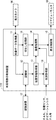
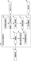
- FIG. 2 is a block diagram illustrating a schematic configuration of the vehicle display control apparatus 10.
- the vehicle display control apparatus 10 includes a video data acquisition unit 11, a recognition unit 12, a position information acquisition unit 13, an image processing unit 14, a display control unit 15, and a cutout processing unit 16. And comprising.
- the video data acquisition unit 11 acquires video data from the rear camera 56 that captures the rear of the vehicle 1.
- the recognition unit 12 collates the recognition dictionary 17 and recognizes another vehicle in the video data acquired by the video data acquisition unit 11.
- the recognition dictionary 17 is a database that stores image data groups of how the vehicle 1 having several representative shapes is viewed from various directions. Note that the recognition dictionary 17 may be stored in a storage unit included in the vehicle display control device 10, stored in a storage device inside or outside the vehicle display control device 10 and the vehicle 1, and usable via a network. It may be.
- the position information acquisition unit 13 acquires information regarding a change in position in the video data of the other vehicle recognized by the recognition unit 12.
- the image processing unit 14 superimposes the movement trajectory of the other vehicle based on the information related to the position change in the video data of the other vehicle recognized by the recognition unit 12 on the video data.
- the display control unit 15 displays video data in which the movement trajectory of the other vehicle is superimposed on the rear view monitor 53 for displaying the video behind the vehicle 1.
- the cutout processing unit 16 cuts out the video data into a display range to be displayed on the rear view monitor 53.
- the image processing unit 14 performs edge detection processing on the video data of the other vehicle recognized by the recognition unit 12 to extract the contour line of the other vehicle.
- a threshold is set for the length and thickness of the contour line in order to exclude unnecessary lines and lines indicating the fine structure in the video data of other vehicles. It is good also as a contour line of other vehicles using a contour line.
- the rear camera 56 generally includes a wide-angle lens, for example, a horizontal field angle of 120 to 180 degrees. For this reason, the cutout processing unit 16 performs cutout processing for setting an appropriate display range on the rear view monitor 53 on the video data captured by the rear camera 56.
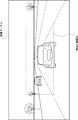
- FIG. 3 is a diagram illustrating an example of video data acquired by the rear camera 56.
- FIG. 4 is clipped video data cut out from the video data in FIG. As shown in FIGS. 3 and 4, the cutout section 16 in the video data A is cut out by the cutout processing unit 16, and cutout video data C is acquired.
- the recognition unit 12 may recognize other vehicles in the video data acquired by the video data acquisition unit 11 at predetermined time intervals. For example, when the rear camera 56 acquires the video behind the vehicle 1 at a frame rate of 30 fps (frame per second), the recognition unit 12 recognizes another vehicle every 20 frames for the acquired video data. To do. In this case, the predetermined interval is 20 seconds / 30 seconds.
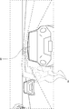
- FIG. 5 is a diagram showing an example of video data (cut-out video data) on which the trajectory of another vehicle is superimposed.
- the contour images 61 a and 61 b of the other vehicle 60 at the time before the current time are superimposed on the video data (cutout video data) as a movement locus.
- the contour image 61a is the contour image of the other vehicle recognized one time before the current time, that is, 20 seconds before 30/30.
- the contour image 61b is the contour image of the other vehicle recognized two times before the current time, that is, 40 seconds before 30 minutes.
- the driver can predict in which direction the other vehicle will move.
- the number of contour images (number of display contours) of other vehicles to be superimposed on the video data (cutout video data) is not limited to 2, and any number may be superimposed as long as it is 1 or more.
- the display control unit 15 generates a contour image in which the shape of the contour is processed when generating a contour image of another vehicle.
- the extracted contour line of the other vehicle may be colored so that the contour image superimposed on the video data is more easily recognized.
- the contour line in the moving direction of the other vehicle may be deleted from the extracted contour line of the other vehicle. Specifically, when the other vehicle 60 is moving in the right direction with respect to the video data as in the example shown in FIG. 5, the contour video 61 a and the contour video 61 b indicating the contour are respectively displayed on the left half and the left end portion. Only a contour line may be used. Furthermore, it is good also as an outline which becomes thin gradually from the moving direction opposite side of another vehicle to a moving direction.
- the driver of the vehicle 1 can accurately grasp the operation of the rear vehicle by superimposing the movement trajectory of the other vehicle on the video data acquired by the rear camera and displaying it on the rear view mirror.
- FIG. 6 is a block diagram illustrating a schematic configuration of the vehicle display control apparatus 110.
- the vehicle display control device 110 has basically the same configuration as the vehicle display control device 10 described with reference to FIG. 2 in the first embodiment, except that the situation acquisition unit 18 is provided. is there.
- the status acquisition unit 18 acquires the status of the vehicle 1 (see FIG. 1) via CAN (CAN: Controller Area Network), various sensors, a navigation system, and the like.
- CAN Controller Area Network
- the period interval in which the recognition unit 12 recognizes another vehicle in the video data acquired by the video data acquisition unit 11 is varied according to the status of the vehicle 1 acquired by the status acquisition unit 18.
- the situation of the vehicle 1 may be a vehicle traveling speed. That is, the situation acquisition unit 18 acquires information related to the traveling speed of the vehicle 1 from a speed sensor or the like.
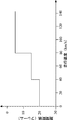
- FIG. 7 is a diagram illustrating an example of the relationship between the vehicle traveling speed and the period interval.
- the image processing unit 14 sets the period interval to 20 frames when the traveling speed V of the vehicle 1 is less than 40 km / h (V ⁇ 40 km / h), and 40 km / h or more and less than 80 km / h (40 km).
- / H ⁇ V ⁇ 80 km / h) the period interval is 15 frames
- the period interval is 5 frames. shorten.
- the rear camera 56 acquires the video behind the vehicle 1 at a frame rate of 30 fps, one frame in the period interval is 1/30 second.
- the number of contour images 61 (number of display contours) of the other vehicle 60 superimposed on the video data (cutout video data) may be changed according to the period interval.
- the number of display contours is 2 as shown in FIG. 8, when it is 15 frames, the number of display contours is 3 as shown in FIG. 9, and when it is 5 frames, it is FIG.
- the number of display contours is set to four.
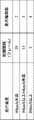
- FIG. 11 shows a list of period intervals and display contour numbers with respect to the traveling speed of the vehicle 1. The faster the traveling speed, the more difficult it is for the driver of the vehicle 1 to notice the sudden approach of another vehicle. By doing so, the driver of the vehicle 1 can grasp the operation of the rear vehicle more accurately. be able to.
- the situation of the vehicle 1 may be an environment (traveling environment) in which the vehicle 1 is traveling. That is, the situation acquisition unit 18 acquires information related to the travel environment from a navigation system or the like.
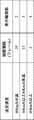
- FIG. 12 is a diagram illustrating an example of the period interval and the number of display contours with respect to the traveling environment. As shown in FIG. 12, if the driving environment is an urban area, the interval is 20 frames and the number of display contours is 2. If the driving environment is a suburb, the interval is 15 frames and the number of display contours is 3. In the case of a dedicated road, the interval is 5 frames and the number of display contours is 4. That is, the image processing unit 14 varies the period interval and the number of display contours according to the traveling environment. The difficulty of the driver of the vehicle 1 noticing suddenly approaching another vehicle changes depending on the driving environment. By doing so, the driver of the vehicle 1 can grasp the operation of the rear vehicle more accurately. Can do.
- the situation of the vehicle 1 may be a legal speed on a road on which the vehicle 1 is traveling. That is, the situation acquisition unit 18 acquires the legal speed on the road on which the vehicle 1 is traveling from a navigation system or the like.
- FIG. 13 is a diagram illustrating an example of the period interval and the number of display contours with respect to the legal speed on the road on which the vehicle 1 is traveling. As shown in FIG. 13, when the legal speed VL of the road on which the vehicle 1 is traveling is less than 40 km / h (VL ⁇ 40 km / h), the interval is 20 frames, the number of display contours is 2, and 40 km / h.
- the period interval is 15 frames and the number of display contours is 3, and when 80 km / h or more (80 km / h ⁇ VL), the period The interval is 5 frames and the number of display contours is 4. That is, the image processing unit 14 shortens the period interval and increases the number of display contours as the legal speed VL increases. The higher the legal speed on the road on which the vehicle 1 is traveling, the more the vehicle 1 travels at a higher speed, so it becomes difficult for the driver of the vehicle 1 to notice the sudden approach of another vehicle. By doing so, the driver of the vehicle 1 can grasp the operation of the rear vehicle more accurately.
- the situation of the vehicle 1 may be a relative speed of the other vehicle recognized by the recognition unit 12 with respect to the vehicle 1. That is, the situation acquisition unit 18 acquires the relative speed of the other vehicle recognized by the recognition unit 12 with respect to the vehicle 1 from a relative speed detection sensor or the like.
- FIG. 14 is a diagram illustrating an example of the period interval and the number of display contours with respect to the relative speed. As shown in FIG. 14, when the relative speed VR is less than 10 km / h (VR ⁇ 10 km / h), the period interval is 20 frames, the number of display contours is 2, and 10 km / h or more and less than 20 km / h (10 km / h).
- the period interval is 15 frames and the number of display contours is 3, and when 20 km / h or more (20 km / h ⁇ VR), the period interval is 5 frames and the number of display contours is 4 To do. That is, the image processing unit 14 shortens the period interval and increases the number of display contours as the relative speed VR is higher. The faster the relative speed, the more difficult it is for the driver of the vehicle 1 to notice the sudden approach of another vehicle. By doing so, the driver of the vehicle 1 can grasp the operation of the rear vehicle more accurately. be able to.
- the relative speed is a relative speed when the speed of the rear vehicle is higher than that of the vehicle 1.
- the situation of the vehicle 1 may be a degree of difficulty in viewing (bad visibility) in the surrounding environment of the vehicle 1. That is, the situation acquisition unit 18 acquires the degree of difficulty in viewing in the surrounding environment of the vehicle 1. Specifically, the situation acquisition unit 18 acquires information on the surrounding environment of the vehicle 1 (weather, daytime / nighttime, presence / absence of fog) from a navigation system or the like, and determines the degree of visual difficulty in the surrounding environment of the vehicle 1. .
- FIG. 15 is a diagram illustrating an example of the period interval and the number of display contours with respect to the degree of visual difficulty in the surrounding environment of the vehicle 1. As shown in FIG.
- the interval is 20 frames and the number of display contours is 2, which is slightly high (night and clear to cloudy, Or, in the case of daytime and fog, or in the daytime and rain), the interval interval is 15 frames and the number of display contours is 3, and in the case of high (night and fog or night and rain), the interval interval is 5 frames and the display contour. Equation 4 is assumed. That is, the image processing unit 14 shortens the period interval and increases the number of display contours as the degree of visual difficulty in the surrounding environment of the vehicle 1 is higher. The higher the degree of visual difficulty in the surrounding environment of the vehicle 1, the harder the driver of the vehicle 1 is aware of the sudden approach of another vehicle. In this way, the driver of the vehicle 1 can operate the rear vehicle. It can be grasped more accurately.
- the situation of the vehicle 1 may be the continuous travel time of the vehicle 1. That is, the situation acquisition unit 18 acquires the continuous travel time of the vehicle 1 from CAN or the like.
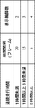
- FIG. 16 is a diagram illustrating an example of the period interval and the number of display contours with respect to the continuous travel time of the vehicle 1. As shown in FIG.
- the interval is 20 frames, the number of display contours is 2, and the time is 1 hour or more and less than 3 hours (1 hr ⁇ T If ⁇ 3 hr), the period interval is 15 frames and the number of display contours is 3, and if 3 hours or more (3 hr ⁇ T), the period interval is 5 frames and the number of display contours is 4. That is, the image processing unit 14 shortens the period interval and increases the number of display contours as the continuous running time of the vehicle 1 is longer. The longer the continuous operation time is, the more likely the driver's judgment of the vehicle 1 becomes dull due to fatigue. By doing so, the driver of the vehicle 1 can more accurately grasp the operation of the rear vehicle. .
- the continuous running time mentioned here excludes a short stop time due to a temporary stop or a signal wait, for example, a stop of less than 5 minutes.
- FIG. 17 is a block diagram illustrating a schematic configuration of the vehicle display control device 210.
- the vehicle display control apparatus 210 includes a video data acquisition unit 11, a recognition unit 12, a position information acquisition unit 213, an image processing unit 214, a display control unit 15, and a cutout processing unit 16. And a warning target vehicle determination unit 219 and a vehicle operation determination unit 220.
- the vehicle operation determination unit 220 determines whether or not the vehicle 1 is operating.
- the operation of the vehicle 1 means a state in which the vehicle 1 can be driven if the accelerator of the vehicle 1 is stepped on, for example, a state in which the engine is operating or an ignition switch is on.
- the video data acquisition unit 11 acquires video data from the rear camera 56 that captures the rear of the vehicle 1 when the vehicle 1 is operating.
- the warning target vehicle determination unit 219 determines whether or not the other vehicle recognized by the recognition unit 12 is a warning target. Specifically, when the relative speed of the other vehicle recognized by the recognition unit 12 with respect to the vehicle 1 is equal to or higher than the specified relative speed and the other vehicle approaches the vehicle 1, the warning target vehicle determination unit 219 May be determined to be a warning target.
- the warning target vehicle determination unit 219 acquires the relative speed of the other vehicle recognized by the recognition unit 12 with respect to the vehicle 1 from a relative speed detection sensor or the like.
- the warning target vehicle determination unit 219 determines that the other vehicle is a warning target when the inter-vehicle distance between the other vehicle recognized by the recognition unit 12 and the vehicle 1 is less than the specified inter-vehicle distance. Good.
- the warning target vehicle determination unit 219 acquires the inter-vehicle distance between the other vehicle recognized by the recognition unit 12 and the vehicle 1 from a millimeter wave radar or the like.
- the position information acquisition unit 213 acquires information related to a change in position in the video data of another vehicle that is determined to be a warning target by the warning target vehicle determination unit 219.
- the image processing unit 214 superimposes the movement trajectory of the other vehicle on the video data based on the information on the change in position in the video data of the other vehicle determined to be the warning target by the warning target vehicle determination unit 219.
- the image processing unit 214 performs edge detection processing on the video data of the other vehicle determined to be the warning target by the warning target vehicle determination unit 219, thereby extracting the contour line of the other vehicle.
- a threshold is set for the length and thickness of the contour line in order to exclude unnecessary lines and lines indicating the fine structure in the video data of other vehicles. It is good also as a contour line of other vehicles using a contour line.
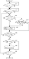
- FIG. 18 is a flowchart illustrating an example of a flow of processing for displaying a warning screen on the display unit 55.
- the vehicle operation determination unit 220 determines whether or not the vehicle 1 is operating (step S2101).
- the recognition unit 12 determines whether or not another vehicle has been recognized (step S2102).
- step S2102 If it is determined in step S2102 that the other vehicle has been recognized (in the case of YES), the warning target vehicle determination unit 219 determines whether the relative speed of the other vehicle with respect to the vehicle 1 is equal to or higher than the specified relative speed (step S2103).
- step S2103 If it is determined in step S2103 that the relative speed of the other vehicle to the vehicle 1 is equal to or greater than the specified relative speed (in the case of YES), the display control unit 15 starts the display of the warning screen or updates the display of the warning screen (Ste S2104). Following step S2104, the recognizing unit 12 determines whether or not the other vehicle still exists in the video captured by the rear camera 56 (step S2106).
- step S2103 If it is determined in step S2103 that the relative speed of the other vehicle to the vehicle 1 is not equal to or greater than the specified relative speed (in the case of NO), the warning target vehicle determination unit 219 determines that the inter-vehicle distance between the other vehicle and the vehicle 1 is less than the specified inter-vehicle distance. It is determined whether or not (step S2105). If it is determined in step S2105 that the inter-vehicle distance between the other vehicle and the vehicle 1 is less than the specified inter-vehicle distance (in the case of YES), the process proceeds to step S2104. If it is determined in step S2105 that the inter-vehicle distance between the other vehicle and the vehicle 1 is not less than the specified inter-vehicle distance (in the case of NO), the process proceeds to step S2106 described above.
- step S2106 If it is determined in step S2106 that the other vehicle is still present in the image captured by the rear camera 56 (YES), the process returns to step S2103. If no other vehicle is present in the image captured by the rear camera 56 in step S2106 (in the case of NO), the display control unit 15 determines whether the warning screen is being displayed (step S2107).
- step S2108 the display control unit 15 cancels the display of the warning screen (step S2108).
- step S2109 the vehicle operation determination unit 220 determines whether or not the vehicle 1 is operating (step S2109). If the vehicle 1 is operating in step S2109 (in the case of YES), the process returns to step S2102. If the vehicle 1 is not operating in step S2109 (NO), the process is terminated.
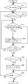
- FIG. 19 is a flowchart illustrating another example of the flow of processing for displaying a warning screen on the display unit 55.
- the warning target vehicle determination unit 219 determines whether or not the relative speed of the other vehicle with respect to the vehicle 1 is equal to or higher than the specified relative speed (In step S2103), it is determined whether the inter-vehicle distance between the other vehicle and the vehicle 1 is less than the specified inter-vehicle distance (step S2105).
- the warning target vehicle determination unit 219 determines whether or not the relative speed of the other vehicle with respect to the vehicle 1 is equal to or higher than the specified relative speed.
- the warning target vehicle determination unit 219 determines whether the relative speed of the other vehicle with respect to the vehicle 1 is equal to or higher than the specified relative speed. Only the determination (step S203) may be performed. The other steps are the same as those described with reference to FIG.
- FIG. 20 is a flowchart illustrating yet another example of the flow of processing for displaying a warning screen on the display unit 55.
- step S2102 when it is determined in step S2102 that the other vehicle has been recognized, it is determined whether the relative speed of the other vehicle with respect to the vehicle 1 is equal to or higher than the specified relative speed (step S2103), and the distance between the other vehicle and the vehicle 1 It is determined whether the distance is less than the specified inter-vehicle distance (step S2105).
- step S2103 the relative speed of the other vehicle with respect to the vehicle 1 is equal to or higher than the specified relative speed
- step S2105 the distance between the other vehicle and the vehicle 1
- the warning target vehicle determination unit 219 determines that the inter-vehicle distance between the other vehicle and the vehicle 1 is less than the specified inter-vehicle distance. Only the determination (step S303) may be performed. The other steps are the same as those described with reference to FIG.
- the warning target vehicle determination unit 219 determines whether the other vehicle recognized by the recognition unit 12 is a warning target based on the relative speed of the other vehicle with respect to the vehicle 1. It is determined by determining whether or not the speed is greater than the relative speed and / or determining whether or not the inter-vehicle distance between the other vehicle and the vehicle 1 is less than the specified inter-vehicle distance.
- the display control unit 15 causes the display unit 55 to display a warning screen when it is determined that the other vehicle is a warning target.
- the warning screen is displayed on the display unit 55 only when it is determined that the other vehicle is a warning target, so that the driver can timely indicate that the rear vehicle has approached. It is possible to grasp and to take an appropriate response to the approaching rear vehicle.
- Embodiment 4 of the present invention will be described below with reference to the drawings. It should be noted that portions common to Embodiments 1 to 3 are denoted by common reference numerals, and description thereof is omitted.
- the configuration of the vehicle display control device according to the present embodiment is basically the same as that of the vehicle display control device 210 described with reference to FIG. 17 in the third embodiment.
- the flow of processing for displaying a warning screen on the display unit 55 is the same as that described with reference to FIG. 18 in the third embodiment.
- the flow of processing for displaying the warning screen on the display unit 55 is the same as that of the modification 6 shown in FIG. 19 or the modification shown in FIG. 7 may be the same.
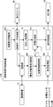
- FIG. 21 is a block diagram showing a schematic configuration of the vehicle display control device 310.
- the vehicle display control device 310 according to the present embodiment includes a situation acquisition unit 318. This point is different from the vehicle display control device 210 described with reference to FIG. 17 in the first embodiment.
- the status acquisition unit 318 acquires the status of the vehicle 1 (see FIG. 1) via CAN (CAN: Controller Area Network), various sensors, a navigation system, and the like. Depending on the situation of the vehicle 1 acquired by the situation acquisition unit 318, the warning target vehicle determination unit 219 varies the specified relative speed and / or the specified inter-vehicle distance.
- CAN Controller Area Network
- the situation of the vehicle 1 may be a vehicle traveling speed. That is, the situation acquisition unit 318 acquires information related to the traveling speed of the vehicle 1 from a speed sensor or the like.
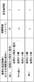
- FIG. 22 is a diagram illustrating an example of the specified relative speed and the specified inter-vehicle distance with respect to the vehicle travel speed. As illustrated in FIG. 22, the warning target vehicle determination unit 219 determines the specified relative speed when the traveling speed V of the vehicle 1 is 20 km / h or more and less than 40 km / h (20 km / h ⁇ V ⁇ 40 km / h).
- the specified relative speed is 210 km / h, 80 km / h or more (80 km / h ⁇ V).
- the specified relative speed may be set to 5 km / h, and the specified relative speed may be decreased as the traveling speed of the vehicle 1 increases.
- the warning target vehicle determination unit 219 is defined when the traveling speed V of the vehicle 1 is 20 km / h or more and less than 40 km / h (20 km / h ⁇ V ⁇ 40 km / h).
- the inter-vehicle distance is 210 m, 40 km / h or more and less than 80 km / h (40 km / h ⁇ V ⁇ 80 km / h)
- the specified inter-vehicle distance is 30 m, 80 km / h or more (80 km / h ⁇ V)
- the specified inter-vehicle distance may be increased as the traveling speed of the vehicle 1 is increased, for example, the specified inter-vehicle distance is 50 m.
- the traveling speed of the vehicle 1 the less the judgment is made because the driver is in a tense state and easily fatigues. For this reason, as the traveling speed of the vehicle 1 increases, it is necessary for the driver to make an appropriate determination with a margin for the approaching rear vehicle. If the specified relative speed is reduced, the driver can grasp the approaching rear vehicle at an earlier time, and thus can make an appropriate determination with a margin for the approaching rear vehicle. Similarly, if the specified inter-vehicle distance is increased, the driver can grasp the approaching rear vehicle at an earlier time, so that he / she can make an appropriate judgment with more margin for the approaching rear vehicle. become. Therefore, the warning target vehicle determination unit 219 can take an appropriate determination with more margin for the approaching rear vehicle by changing the specified relative speed and / or the specified inter-vehicle distance based on the vehicle traveling speed. It becomes like this.
- the number of contour images 61 (the number of display contours) of the other vehicle 60 to be superimposed on the video data (cutout video data) may be changed according to the vehicle traveling speed acquired by the situation acquisition unit 318. As shown in FIG. 22, when the traveling speed V of the vehicle 1 is 20 km / h or more and less than 40 km / h (20 km / h ⁇ V ⁇ 40 km / h), the number of display contours is set to 2, 40 km / h or more.
- the number of display contours is 3, and when the speed is 80 km / h or more (80 km / h ⁇ V), the number of display contours is 4. .
- the situation of the vehicle 1 may be an environment (traveling environment) in which the vehicle 1 is traveling. That is, the situation acquisition unit 318 acquires information related to the travel environment from a navigation system or the like.
- FIG. 23 is a diagram illustrating an example of the specified relative speed and the specified inter-vehicle distance with respect to the traveling environment. As shown in FIG. 23, the warning target vehicle determination unit 219 has a specified relative speed of 15 km / h when the driving environment is an urban area, a specified relative speed of 210 km / h when the driving environment is a suburb, an expressway, etc. The specified relative speed is 5 km / h in the case of an automobile-only road.
- the warning target vehicle determination unit 219 determines that the specified inter-vehicle distance is 210 m when the driving environment is an urban area, the specified inter-vehicle distance is 30 m when the driving environment is a suburb, and an automobile such as an expressway. In the case of a dedicated road, the specified inter-vehicle distance is 50 m.
- the traveling speed of the vehicle 1 is faster than when the driving environment is a suburb or a city area. Further, when the traveling environment is in the suburbs, the traveling speed of the vehicle 1 is faster than in the case of an urban area.
- the traveling speed of the vehicle 1 is increased, the driver is in a tense state and is easily fatigued, so that the judgment power is reduced. For this reason, as the traveling speed of the vehicle 1 increases, it is necessary for the driver to make an appropriate determination with a margin for the approaching rear vehicle. If the specified relative speed is reduced, the driver can grasp the approaching rear vehicle at an earlier time, and thus can make an appropriate determination with a margin for the approaching rear vehicle.
- the warning target vehicle determination unit 219 can make an appropriate determination with more margin for the approaching rear vehicle by changing the specified relative speed and / or the specified inter-vehicle distance based on the driving environment. become.
- the number of contour images 61 (the number of display contours) of the other vehicle 60 to be superimposed on the video data (cut-out video data) may be changed according to the traveling environment acquired by the situation acquisition unit 318. As shown in FIG. 23, when the driving environment is an urban area, the number of displayed contours is 2, when the driving environment is a suburb, the number of displayed contours is 3, and when the driving environment is an automobile-only road such as an expressway, the display is performed. Set the number of contours to 4. By doing in this way, the driver
- the situation of the vehicle 1 may be a degree of difficulty in viewing (bad visibility) in the surrounding environment of the vehicle 1. That is, the situation acquisition unit 318 acquires the degree of difficulty in viewing in the surrounding environment of the vehicle 1. Specifically, the situation acquisition unit 318 acquires information on the surrounding environment of the vehicle 1 (weather, daytime / nighttime, presence / absence of fog) from a navigation system or the like, and determines the degree of visual difficulty in the surrounding environment of the vehicle 1. .
- FIG. 24 is a diagram illustrating an example of the specified relative speed and the specified inter-vehicle distance with respect to the degree of visual difficulty in the surrounding environment of the vehicle 1. As shown in FIG.
- the warning target vehicle determination unit 219 sets the specified relative speed to 15 km / h, which is slightly high (nighttime) when the degree of visual difficulty in the surrounding environment of the vehicle 1 is low (daytime and clear to cloudy).
- the specified relative speed is 210 km / h, and in case of high (nighttime and foggy, nighttime and rain), the specified relative speed is 5 km. / H.
- the specified relative speed may be decreased as the degree of visual difficulty in the surrounding environment of the vehicle 1 is higher.
- the warning target vehicle determination unit 219 sets the specified inter-vehicle distance to 210 m, which is slightly higher (nighttime) when the degree of visual difficulty in the surrounding environment of the vehicle 1 is low (daytime and clear to cloudy).
- the specified inter-vehicle distance is 30 m. . That is, the specified inter-vehicle distance may be increased as the degree of visual difficulty in the surrounding environment of the vehicle 1 is higher.
- the warning target vehicle determination unit 219 makes an appropriate determination with more margin to the approaching rear vehicle by changing the specified relative speed and / or the specified inter-vehicle distance based on the degree of visual difficulty. You can take it.
- the number of contour images 61 of the other vehicle 60 to be superimposed on the video data (cutout video data) (the number of display contours) is changed according to the degree of visual difficulty in the surrounding environment acquired by the situation acquisition unit 318.
- the degree of visual difficulty in the surrounding environment of the vehicle 1 is low (daytime and sunny to cloudy)
- the number of display contours is set to 2 and is slightly higher (night and sunny to cloudy, daytime and fog). If there is or is daytime and rain, the display contour number is 3, and if it is high (night and fog or night and rain), the display contour number is 4.
- the present invention is not limited to the above-described embodiment, and can be appropriately changed without departing from the spirit of the present invention.
- the present invention is not limited to this, and the video data acquired by the center console or the like is displayed. Also good.
- the video data acquired by the rear camera is subjected to the processing for cutting out the range to be displayed on the display unit, but the rear camera is configured to acquire video data that matches the display range of the display unit. Also good. In this case, the cutting process becomes unnecessary.
- Processing in each part of the vehicle display control apparatus can be realized by causing a computer or the like to execute a program. More specifically, in the vehicle display control device, the program stored in the program memory is loaded into the main storage device, and the program is executed under the control of the CPU.
- the program can be stored using various types of non-transitory computer readable media and supplied to a computer.
- Non-transitory computer readable media include various types of tangible storage media.
- non-transitory computer-readable media examples include magnetic recording media (for example, flexible disks, magnetic tapes, hard disk drives), magneto-optical recording media (for example, magneto-optical disks), CD-ROMs (Read Only Memory), CD-R, CD-R / W, semiconductor memory (for example, mask ROM, PROM (Programmable ROM), EPROM (Erasable PROM), flash ROM, RAM (Random Access Memory)).
- the program may be supplied to the computer by various types of temporary computer readable media. Examples of transitory computer readable media include electrical signals, optical signals, and electromagnetic waves.
- the temporary computer-readable medium can supply the program to the computer via a wired communication path such as an electric wire and an optical fiber, or a wireless communication path.
- the processing in each part of the vehicle display control device is not limited to being realized by software by a program, but may be realized by any combination of hardware, firmware, and software.
- the vehicle display control apparatus and at least one of the display unit and the rear camera may be combined to form one vehicle display system.
- the vehicle display control apparatus can be used as an image display apparatus implemented in a passenger car, for example.
Landscapes
- Engineering & Computer Science (AREA)
- Multimedia (AREA)
- Mechanical Engineering (AREA)
- Physics & Mathematics (AREA)
- General Physics & Mathematics (AREA)
- Theoretical Computer Science (AREA)
- Signal Processing (AREA)
- Traffic Control Systems (AREA)
Abstract
車両用表示制御装置(10)であって、車両の後方を撮影する後方カメラ(56)から映像データを取得する映像データ取得部(11)と、映像データにおける他車両を認識する認識部(12)と、認識部(12)によって認識された他車両の映像データにおける位置の変化に関する情報を取得する位置情報取得部(13)と、上記位置の変化に関する情報に基づく他車両の移動軌跡を映像データに重畳する画像処理部(14)と、車両(1)の後方の映像を表示させるためのリヤビューモニタ(53)に移動軌跡が重畳された映像データを表示させる表示制御部(15)と、を備えるものである。
Description
本発明は、車両用表示制御装置、車両表示制御方法及びプログラムに関する。
自動車等に用いられる後方確認用のルームミラー(リヤビューミラー)などにおいて、電子表示化が進められている。
特許文献1には、カメラによって撮影された車両の後方(後側方)の撮影画像に対し、その撮影画像中における他車両の位置またはその近傍に目印を重畳し、目印が重畳された撮影画像における該目印の大きさの変化の割合が車両と他車両との車間距離の変化の割合よりも大きくなるようにディスプレイに表示させる、車両の後側方撮影装置が記載されている。
運転中、運転者は、常時リヤビューモニタを見ているわけではない。このため、運転者がリヤビューモニタを見たときに、それ以前には意識していなかった後方車両に突然気付くケースがある。このようなケースは、例えば、自車が走行中の車線に隣接した車線を走行している後方車両が、突然、自車の後方へと移動してきたときや、後方車両が比較的大きな相対速度で自車の後方に近接してきたときなどにおいて起こりうる。運転者が後方車両に突然気付いた場合、運転者は後方車両がそれ以前にどのような動作していたのか(後方車両がどのような方向から近づいてきたのか)が分からないため、後方車両のそれ以降の動作予測(後方車両がどのような方向に動くかの予測)が困難となるという問題があった。特許文献1に記載の技術は、運転者に対して後方車両の車間距離を適切に認識させることを目的としたものであり、特許文献1に記載の技術をリヤビューモニタに適用しても上記問題は解決されない。
本実施形態は、以上の背景に鑑みなされたものであり、後方車両の動作を的確に把握することができる車両用表示制御装置、車両用表示制御システム、車両表示制御方法及びプログラムを提供することを目的とする。
本実施形態は、車両用表示制御装置であって、車両の後方を撮影する後方カメラから映像データを取得する映像データ取得部と、前記映像データにおける他車両を認識する認識部と、前記認識部によって認識された他車両の前記映像データにおける位置の変化に関する情報を取得する位置情報取得部と、前記位置の変化に関する情報に基づく他車両の移動軌跡を前記映像データに重畳する画像処理部と、前記車両の後方の映像を表示させるためのリヤビューモニタに前記移動軌跡が重畳された映像データを表示させる表示制御部と、を備えるものである。
本実施形態は、車両用表示制御方法であって、車両の後方を撮影する後方カメラから映像データを取得するステップと、前記映像データにおける他車両を認識するステップと、
当該認識された他車両の前記映像データにおける位置の変化に関する情報を取得するステップと、前記位置の変化に関する情報に基づく他車両の移動軌跡を前記映像データに重畳するステップと、前記車両の後方の映像を表示させるためのリヤビューモニタに前記移動軌跡が重畳された映像データを表示させるステップと、を備えるものである。
当該認識された他車両の前記映像データにおける位置の変化に関する情報を取得するステップと、前記位置の変化に関する情報に基づく他車両の移動軌跡を前記映像データに重畳するステップと、前記車両の後方の映像を表示させるためのリヤビューモニタに前記移動軌跡が重畳された映像データを表示させるステップと、を備えるものである。
本実施形態は、車両用表示制御のためのプログラムであって、車両の後方を撮影する後方カメラから映像データを取得する処理手順と、前記映像データにおける他車両を認識する処理手順と、当該認識された他車両の前記映像データにおける位置の変化に関する情報を取得する処理手順と、前記位置の変化に関する情報に基づく他車両の移動軌跡を前記映像データに重畳する処理手順と、前記車両の後方の映像を表示させるためのリヤビューモニタに前記移動軌跡が重畳された映像データを表示させる処理手順と、をコンピュータに実行させるものである。
本実施形態によれば、後方車両の動作を的確に把握することができる。
[実施の形態1]
以下、図面を参照して本発明の実施の形態1について説明する。
まず、本発明にかかる車両用表示制御装置を搭載する車両1の運転室内の配置の一例について説明する。
図1は、車両(自動車)1の運転室内における配置の一例について説明する図である。図1に示すように、車両1の運転室内は一般的な構成であり、ステアリングホイール50、ダッシュボード51、ウインドシールド52、センターコンソール54、車両の走行速度やエンジン回転数などを表示するクラスタパネル57、などを備える。近年、センターコンソール54には、ナビゲーション画面などを表示する表示部55が設けられていることも多い。リヤビューモニタ53は、一般的な車両における後方確認用のリヤビューミラーと同様の位置、すなわち、ウインドシールド52の上部中央付近に配置されている。
以下、図面を参照して本発明の実施の形態1について説明する。
まず、本発明にかかる車両用表示制御装置を搭載する車両1の運転室内の配置の一例について説明する。
図1は、車両(自動車)1の運転室内における配置の一例について説明する図である。図1に示すように、車両1の運転室内は一般的な構成であり、ステアリングホイール50、ダッシュボード51、ウインドシールド52、センターコンソール54、車両の走行速度やエンジン回転数などを表示するクラスタパネル57、などを備える。近年、センターコンソール54には、ナビゲーション画面などを表示する表示部55が設けられていることも多い。リヤビューモニタ53は、一般的な車両における後方確認用のリヤビューミラーと同様の位置、すなわち、ウインドシールド52の上部中央付近に配置されている。
次に、本実施の形態にかかる車両用表示制御装置10の概略構成について説明する。
図2は、車両用表示制御装置10の概略構成を示すブロック図である。図2に示すように、車両用表示制御装置10は、映像データ取得部11と、認識部12と、位置情報取得部13と、画像処理部14と、表示制御部15と、切出し処理部16と、を備える。
図2は、車両用表示制御装置10の概略構成を示すブロック図である。図2に示すように、車両用表示制御装置10は、映像データ取得部11と、認識部12と、位置情報取得部13と、画像処理部14と、表示制御部15と、切出し処理部16と、を備える。
映像データ取得部11は、車両1の後方を撮影する後方カメラ56からの映像データを取得する。認識部12は、認識辞書17を照合し、映像データ取得部11において取得された映像データにおける他車両を認識する。認識辞書17は、いくつかの代表的な形状の車両1について、それぞれ、様々な方角からの見え方の画像データ群が格納されたデータベースである。なお、認識辞書17は、車両用表示制御装置10が備える記憶部に記憶されていてもよく、車両用表示制御装置10と車両1の内部または外部における記憶装置に記憶されネットワークを介して利用可能とするものであってもよい。
位置情報取得部13は、認識部12によって認識された他車両の映像データにおける位置の変化に関する情報を取得する。画像処理部14は、認識部12によって認識された他車両の映像データにおける位置の変化に関する情報に基づく他車両の移動軌跡を映像データに重畳する。表示制御部15は、車両1の後方の映像を表示させるためのリヤビューモニタ53に他車両の移動軌跡が重畳された映像データを表示させる。切出し処理部16は、映像データに対し、リヤビューモニタ53に表示させる表示範囲への切出しを行う。
画像処理部14は、認識部12が認識した他車両の映像データに対し、エッジ検出処理を行うことで、他車両の輪郭線などを抽出する。抽出した輪郭線に対しては、不要な線や他車両の映像データにおける細かい構成を示す線を除外するために、輪郭線の長さや太さに対してしきい値を設け、しきい値以上の輪郭線を用いて他車両の輪郭線としてもよい。
後方カメラ56は、例えば横方向画角120度~180度といった、広角なレンズを備えていることが一般的である。このため、切出し処理部16は、後方カメラ56により撮影された映像データに対し、リヤビューモニタ53における適切な表示範囲にするための切出し処理を行う。図3は、後方カメラ56によって取得された映像データの一例を示す図である。図4は、図3における映像データから切出された切出し映像データである。図3および図4に示すように、切出し処理部16によって、映像データAにおける切出し範囲Bが切出され、切出し映像データCが取得される。
認識部12は、映像データ取得部11において取得された映像データにおける他車両を所定の期間間隔で認識するようにしてもよい。例えば、後方カメラ56が車両1の後方の映像を30fps(frame per second)のフレームレートで取得する場合に、認識部12が、取得した映像データに対し20フレーム毎に他車両の認識を行うとする。この場合、所定の期間間隔は30分の20秒となる。
図5は、他車両の軌跡が重畳された映像データ(切出し映像データ)の一例を示す図である。図5に示すように、映像データ(切出し映像データ)には、他車両60における、現時点より前の時点の輪郭映像61a,61bが移動軌跡として重畳されている。所定の期間間隔が30分の20秒とすると、現時点より1つ前、つまり、30分の20秒前に認識した他車両の輪郭映像が輪郭映像61aである。また、現時点より2つ前、つまり30分の40秒前に認識した他車両の輪郭映像が輪郭映像61bである。このように他車両の輪郭映像を表示させることで、運転者は他車両がどのような方向から移動してきたのかを把握することができる。これにより、運転者は、他車両がどのような方向へと移動するのか予測をすることができる。なお、映像データ(切出し映像データ)に重畳する他車両の輪郭映像の数(表示輪郭数)は2に限らず、1以上であれば幾つ重畳してもよい。
表示制御部15は、他車両の輪郭映像を生成する際に、輪郭の形態を加工した輪郭映像を生成すると、より効果的である。例えば、抽出した他車両の輪郭線に着色処理を行い、映像データに重畳された輪郭映像がより認識されやすいようにしてもよい。さらには、抽出された他車両の輪郭線に対して、他車両の移動方向の輪郭線を消去してもよい。具体的には、図5に示す例のように他車両60が映像データに対して右方向に移動しているときは、輪郭線を示す輪郭映像61aおよび輪郭映像61bを各々左半分や左端部分のみの輪郭線としてもよい。さらには、他車両の移動方向反対側から移動方向にかけて徐々に薄くなる輪郭線としてもよい。
以上のように、後方カメラが取得した映像データに他車両の移動軌跡を重畳してリヤビューミラーに表示させることにより、車両1の運転者が後方車両の動作を的確に把握することができる。
[実施の形態2]
以下、図面を参照して本発明の実施の形態2について説明する。なお、実施の形態1と共通の部分には共通の符号を付してその説明を省略する。
図6は、車両用表示制御装置110の概略構成を示すブロック図である。図6に示すように、車両用表示制御装置110は、状況取得部18を備えること以外は、実施の形態1において図2を用いて説明した車両用表示制御装置10と基本的に同じ構成である。
以下、図面を参照して本発明の実施の形態2について説明する。なお、実施の形態1と共通の部分には共通の符号を付してその説明を省略する。
図6は、車両用表示制御装置110の概略構成を示すブロック図である。図6に示すように、車両用表示制御装置110は、状況取得部18を備えること以外は、実施の形態1において図2を用いて説明した車両用表示制御装置10と基本的に同じ構成である。
状況取得部18は、CAN(CAN:Controller Area Network)、各種センサ、ナビゲーションシステムなどを介して車両1(図1参照)の状況を取得する。画像処理部14では、状況取得部18が取得した車両1の状況に応じて、認識部12が映像データ取得部11において取得された映像データにおける他車両を認識する期間間隔を変動させる。
車両1の状況は、車両走行速度であってもよい。つまり、状況取得部18は、速度センサなどから車両1の走行速度に関する情報を取得する。図7は、車両走行速度と期間間隔との関係の一例を示す図である。図7に示すように、画像処理部14は、車両1の走行速度Vが、40km/h未満(V<40km/h)のとき期間間隔を20フレーム、40km/h以上80km/h未満(40km/h≦V<80km/h)のとき期間間隔を15フレーム、80km/h以上(80km/h≦V)のとき期間間隔を5フレームという具合に、車両1の走行速度が速いほど期間間隔を短くする。なお、後方カメラ56が車両1の後方の映像を30fpsのフレームレートで取得する場合、期間間隔における1フレームは1/30秒である。
映像データ(切出し映像データ)に重畳する他車両60の輪郭映像61の数(表示輪郭数)を期間間隔に応じて変更してもよい。例えば、期間間隔が、20フレームの場合は図8に示すように表示輪郭数を2に、15フレームの場合は図9に示すように表示輪郭数を3に、5フレームの場合は図10に示すように表示輪郭数を4にする。図11に、車両1の走行速度に対する期間間隔および表示輪郭数の一覧を示す。走行速度が速いほど車両1の運転者は突発的な他車両の接近に気付くのが困難になるが、このようにすることで、車両1の運転者が後方車両の動作をより的確に把握することができる。
[変形例1]
車両1の状況は、車両1が走行している環境(走行環境)であってもよい。つまり、状況取得部18は、ナビゲーションシステムなどから走行環境に関する情報を取得する。図12は、走行環境に対する期間間隔および表示輪郭数の一例を示す図である。図12に示すように、走行環境が、市街地である場合には期間間隔20フレーム、表示輪郭数2とし、郊外である場合には期間間隔15フレーム、表示輪郭数3とし、高速道路等の自動車専用道路である場合には期間間隔5フレーム、表示輪郭数4とする。つまり、画像処理部14は、走行環境に応じて期間間隔、表示輪郭数を変動させる。走行環境によって車両1の運転者が突発的な他車両の接近に気付く困難さが変わってくるが、このようにすることで、車両1の運転者が後方車両の動作をより的確に把握することができる。
車両1の状況は、車両1が走行している環境(走行環境)であってもよい。つまり、状況取得部18は、ナビゲーションシステムなどから走行環境に関する情報を取得する。図12は、走行環境に対する期間間隔および表示輪郭数の一例を示す図である。図12に示すように、走行環境が、市街地である場合には期間間隔20フレーム、表示輪郭数2とし、郊外である場合には期間間隔15フレーム、表示輪郭数3とし、高速道路等の自動車専用道路である場合には期間間隔5フレーム、表示輪郭数4とする。つまり、画像処理部14は、走行環境に応じて期間間隔、表示輪郭数を変動させる。走行環境によって車両1の運転者が突発的な他車両の接近に気付く困難さが変わってくるが、このようにすることで、車両1の運転者が後方車両の動作をより的確に把握することができる。
[変形例2]
車両1の状況は、車両1が走行している道路における法定速度であってもよい。つまり、状況取得部18は、ナビゲーションシステムなどから車両1が走行している道路における法定速度を取得する。図13は、車両1が走行している道路における法定速度に対する期間間隔および表示輪郭数の一例を示す図である。図13に示すように、車両1が走行している道路の法定速度VLが、40km/h未満(VL<40km/h)である場合には期間間隔20フレーム、表示輪郭数2とし、40km/h以上80km/h未満(40km/h≦VL<80km/h)である場合には期間間隔15フレーム、表示輪郭数3とし、80km/h以上(80km/h≦VL)である場合には期間間隔5フレーム、表示輪郭数4とする。つまり、画像処理部14は、法定速度VLが速いほど期間間隔を短くし、表示輪郭数を多くする。車両1が走行している道路における法定速度が速いほど車両1が高速で走行することが多くなるため車両1の運転者は突発的な他車両の接近に気付くのが困難になるが、このようにすることで、車両1の運転者が後方車両の動作をより的確に把握することができる。
車両1の状況は、車両1が走行している道路における法定速度であってもよい。つまり、状況取得部18は、ナビゲーションシステムなどから車両1が走行している道路における法定速度を取得する。図13は、車両1が走行している道路における法定速度に対する期間間隔および表示輪郭数の一例を示す図である。図13に示すように、車両1が走行している道路の法定速度VLが、40km/h未満(VL<40km/h)である場合には期間間隔20フレーム、表示輪郭数2とし、40km/h以上80km/h未満(40km/h≦VL<80km/h)である場合には期間間隔15フレーム、表示輪郭数3とし、80km/h以上(80km/h≦VL)である場合には期間間隔5フレーム、表示輪郭数4とする。つまり、画像処理部14は、法定速度VLが速いほど期間間隔を短くし、表示輪郭数を多くする。車両1が走行している道路における法定速度が速いほど車両1が高速で走行することが多くなるため車両1の運転者は突発的な他車両の接近に気付くのが困難になるが、このようにすることで、車両1の運転者が後方車両の動作をより的確に把握することができる。
[変形例3]
車両1の状況は、認識部12によって認識された他車両の車両1に対する相対速度であってもよい。つまり、状況取得部18は、相対速度検出センサなどから、認識部12によって認識された他車両の車両1に対する相対速度を取得する。図14は、相対速度に対する期間間隔および表示輪郭数の一例を示す図である。図14に示すように、相対速度VRが、10km/h未満(VR<10km/h)である場合には期間間隔20フレーム、表示輪郭数2とし、10km/h以上20km/h未満(10km/h≦VR<20km/h)である場合には期間間隔15フレーム、表示輪郭数3とし、20km/h以上(20km/h≦VR)である場合には期間間隔5フレーム、表示輪郭数4とする。つまり、画像処理部14は、相対速度VRが速いほど期間間隔を短くし、表示輪郭数を多くする。相対速度が速いほど車両1の運転者は突発的な他車両の接近に気付くのが困難になるが、このようにすることで、車両1の運転者が後方車両の動作をより的確に把握することができる。ここで言う相対速度とは、車両1より後方車両の速度が速い場合の相対速度である。
車両1の状況は、認識部12によって認識された他車両の車両1に対する相対速度であってもよい。つまり、状況取得部18は、相対速度検出センサなどから、認識部12によって認識された他車両の車両1に対する相対速度を取得する。図14は、相対速度に対する期間間隔および表示輪郭数の一例を示す図である。図14に示すように、相対速度VRが、10km/h未満(VR<10km/h)である場合には期間間隔20フレーム、表示輪郭数2とし、10km/h以上20km/h未満(10km/h≦VR<20km/h)である場合には期間間隔15フレーム、表示輪郭数3とし、20km/h以上(20km/h≦VR)である場合には期間間隔5フレーム、表示輪郭数4とする。つまり、画像処理部14は、相対速度VRが速いほど期間間隔を短くし、表示輪郭数を多くする。相対速度が速いほど車両1の運転者は突発的な他車両の接近に気付くのが困難になるが、このようにすることで、車両1の運転者が後方車両の動作をより的確に把握することができる。ここで言う相対速度とは、車両1より後方車両の速度が速い場合の相対速度である。
[変形例4]
車両1の状況は、車両1の周辺環境における目視困難(視界の悪さ)の度合いであってもよい。つまり、状況取得部18は、車両1の周辺環境における目視困難の度合いを取得する。具体的には、状況取得部18は、ナビゲーションシステムなどから車両1の周辺環境(天気、昼間・夜間、霧の有無)に関する情報を取得し、車両1の周辺環境における目視困難の度合いを判断する。図15は、車両1の周辺環境における目視困難の度合いに対する期間間隔および表示輪郭数の一例を示す図である。図15に示すように、車両1の周辺環境における目視困難の度合いが、低い(昼間かつ晴天~曇天)場合には期間間隔20フレーム、表示輪郭数2とし、やや高い(夜間かつ晴天~曇天、または、昼間かつ霧あり、または、昼間かつ雨)場合には期間間隔15フレーム、表示輪郭数3とし、高い(夜間かつ霧あり、または、夜間かつ雨)場合には期間間隔5フレーム、表示輪郭数4とする。つまり、画像処理部14は、車両1の周辺環境における目視困難の度合いが高いほど期間間隔を短くし、表示輪郭数を多くする。車両1の周辺環境における目視困難の度合いが高いほど車両1の運転者は突発的な他車両の接近に気付き難くなるが、このようにすることで、車両1の運転者が後方車両の動作をより的確に把握することができる。
車両1の状況は、車両1の周辺環境における目視困難(視界の悪さ)の度合いであってもよい。つまり、状況取得部18は、車両1の周辺環境における目視困難の度合いを取得する。具体的には、状況取得部18は、ナビゲーションシステムなどから車両1の周辺環境(天気、昼間・夜間、霧の有無)に関する情報を取得し、車両1の周辺環境における目視困難の度合いを判断する。図15は、車両1の周辺環境における目視困難の度合いに対する期間間隔および表示輪郭数の一例を示す図である。図15に示すように、車両1の周辺環境における目視困難の度合いが、低い(昼間かつ晴天~曇天)場合には期間間隔20フレーム、表示輪郭数2とし、やや高い(夜間かつ晴天~曇天、または、昼間かつ霧あり、または、昼間かつ雨)場合には期間間隔15フレーム、表示輪郭数3とし、高い(夜間かつ霧あり、または、夜間かつ雨)場合には期間間隔5フレーム、表示輪郭数4とする。つまり、画像処理部14は、車両1の周辺環境における目視困難の度合いが高いほど期間間隔を短くし、表示輪郭数を多くする。車両1の周辺環境における目視困難の度合いが高いほど車両1の運転者は突発的な他車両の接近に気付き難くなるが、このようにすることで、車両1の運転者が後方車両の動作をより的確に把握することができる。
[変形例5]
車両1の状況は、車両1の連続走行時間であってもよい。つまり、状況取得部18は、CANなどから車両1の連続走行時間を取得する。図16は、車両1の連続走行時間に対する期間間隔および表示輪郭数の一例を示す図である。図16に示すように、車両1の連続走行時間Tが、1時間未満(T<1hr)である場合には期間間隔20フレーム、表示輪郭数2とし、1時間以上3時間未満
(1hr≦T<3hr)である場合には期間間隔15フレーム、表示輪郭数3とし、3時間以上(3hr≦T)である場合には期間間隔5フレーム、表示輪郭数4とする。つまり、画像処理部14は、車両1の連続走行時間が長いほど期間間隔を短くし、表示輪郭数を多くする。連続運転時間が長くなればなるほど疲労によって車両1の運転者の判断が鈍りがちになるが、このようにすることで、車両1の運転者が後方車両の動作をより的確に把握することができる。ここで言う連続走行時間とは、一時停止や信号待ちによる短時間の停止時間、例えば5分未満の停止などを除外する。
車両1の状況は、車両1の連続走行時間であってもよい。つまり、状況取得部18は、CANなどから車両1の連続走行時間を取得する。図16は、車両1の連続走行時間に対する期間間隔および表示輪郭数の一例を示す図である。図16に示すように、車両1の連続走行時間Tが、1時間未満(T<1hr)である場合には期間間隔20フレーム、表示輪郭数2とし、1時間以上3時間未満
(1hr≦T<3hr)である場合には期間間隔15フレーム、表示輪郭数3とし、3時間以上(3hr≦T)である場合には期間間隔5フレーム、表示輪郭数4とする。つまり、画像処理部14は、車両1の連続走行時間が長いほど期間間隔を短くし、表示輪郭数を多くする。連続運転時間が長くなればなるほど疲労によって車両1の運転者の判断が鈍りがちになるが、このようにすることで、車両1の運転者が後方車両の動作をより的確に把握することができる。ここで言う連続走行時間とは、一時停止や信号待ちによる短時間の停止時間、例えば5分未満の停止などを除外する。
[実施の形態3]
以下、図面を参照して本発明の実施の形態3について説明する。なお、実施の形態1、実施の形態2と共通の部分には共通の符号を付してその説明を省略する。
まず、本実施の形態にかかる車両用表示制御装置210の概略構成について説明する。
図17は、車両用表示制御装置210の概略構成を示すブロック図である。図17に示すように、車両用表示制御装置210は、映像データ取得部11と、認識部12と、位置情報取得部213と、画像処理部214と、表示制御部15と、切出し処理部16と、警告対象車両判断部219と、車両動作判断部220と、を備える。
以下、図面を参照して本発明の実施の形態3について説明する。なお、実施の形態1、実施の形態2と共通の部分には共通の符号を付してその説明を省略する。
まず、本実施の形態にかかる車両用表示制御装置210の概略構成について説明する。
図17は、車両用表示制御装置210の概略構成を示すブロック図である。図17に示すように、車両用表示制御装置210は、映像データ取得部11と、認識部12と、位置情報取得部213と、画像処理部214と、表示制御部15と、切出し処理部16と、警告対象車両判断部219と、車両動作判断部220と、を備える。
車両動作判断部220は、車両1が動作中であるか否かを判断する。ここで、車両1が動作中とは、車両1のアクセルを踏めば車両1を走行させることが可能な状態で、例えばエンジンが稼働中の状態や、イグニッションスイッチがオンの状態をいう。映像データ取得部11は、車両1が動作中である場合に、車両1の後方を撮影する後方カメラ56からの映像データを取得する。
警告対象車両判断部219は、認識部12により認識された他車両が警告対象であるか否かの判断を行う。具体的には、警告対象車両判断部219は、認識部12により認識された他車両の車両1に対する相対速度が規定相対速度以上で、当該他車両が車両1に接近する場合に、当該他車両が警告対象であると判断してもよい。なお、警告対象車両判断部219は、相対速度検出センサなどから、認識部12により認識された他車両の車両1に対する相対速度を取得する。また、警告対象車両判断部219は、認識部12により認識された他車両と車両1との車間距離が規定車間距離未満になった場合に、当該他車両が警告対象であると判断してもよい。なお、警告対象車両判断部219は、ミリ波レーダーなどから、認識部12により認識された他車両と車両1との車間距離を取得する。
位置情報取得部213は、警告対象車両判断部219により警告対象であると判断された他車両の映像データにおける位置の変化に関する情報を取得する。画像処理部214は、警告対象車両判断部219により警告対象であると判断された他車両の映像データにおける位置の変化に関する情報に基づく他車両の移動軌跡を映像データに重畳する。画像処理部214は、警告対象車両判断部219により警告対象であると判断された他車両の映像データに対し、エッジ検出処理を行うことで、他車両の輪郭線などを抽出する。抽出した輪郭線に対しては、不要な線や他車両の映像データにおける細かい構成を示す線を除外するために、輪郭線の長さや太さに対してしきい値を設け、しきい値以上の輪郭線を用いて他車両の輪郭線としてもよい。
次に、図18を参照して、表示部55に警告画面を表示させる処理の流れについて説明する。なお、以下の説明において、車両用表示制御装置210の構成については図17を適宜参照する。
図18は、表示部55に警告画面を表示させる処理の流れの一例を示すフローチャートである。図18に示すように、まず、車両動作判断部220が、車両1が動作中であるか否かを判断する(ステップS2101)。ステップS2101で車両1が動作中であると判断した場合(YESの場合)、認識部12が、他車両を認識したか否かを判断する(ステップS2102)。ステップS2102で他車両を認識したと判断した場合(YESの場合)、警告対象車両判断部219が、他車両の車両1に対する相対速度が規定相対速度以上か否かを判断する(ステップS2103)。
図18は、表示部55に警告画面を表示させる処理の流れの一例を示すフローチャートである。図18に示すように、まず、車両動作判断部220が、車両1が動作中であるか否かを判断する(ステップS2101)。ステップS2101で車両1が動作中であると判断した場合(YESの場合)、認識部12が、他車両を認識したか否かを判断する(ステップS2102)。ステップS2102で他車両を認識したと判断した場合(YESの場合)、警告対象車両判断部219が、他車両の車両1に対する相対速度が規定相対速度以上か否かを判断する(ステップS2103)。
ステップS2103で他車両の車両1に対する相対速度が規定相対速度以上であると判断した場合(YESの場合)、表示制御部15が、警告画面の表示の開始、または警告画面の表示を更新する(ステップS2104)。ステップS2104に続き、認識部12が、他車両はまだ後方カメラ56により撮影された映像内に存在するか否かを判断する(ステップS2106)。
ステップS2103で他車両の車両1に対する相対速度が規定相対速度以上ではないと判断した場合(NOの場合)、警告対象車両判断部219が、他車両と車両1との車間距離は規定車間距離未満であるか否かを判断する(ステップS2105)。ステップS2105で他車両と車両1との車間距離は規定車間距離未満であると判断した場合(YESの場合)、処理をステップS2104に進める。ステップS2105で他車両と車両1との車間距離は規定車間距離未満ではないと判断した場合(NOの場合)、上述したステップS2106に処理を進める。
ステップS2106で他車両はまだ後方カメラ56により撮影された映像内に存在する場合(YESの場合)、処理をステップS2103に戻す。ステップS2106で他車両は後方カメラ56により撮影された映像内に存在しない場合(NOの場合)、表示制御部15が、警告画面は表示中か否かを判断する(ステップS2107)。
ステップS2107で警告画面は表示中である場合(YESの場合)、表示制御部15が、警告画面の表示を解除する(ステップS2108)。ステップS2108に続き、車両動作判断部220が、車両1が動作中か否かを判断する(ステップS2109)。ステップS2109で車両1が動作中の場合(YESの場合)、処理をステップS2102に戻す。ステップS2109で車両1が動作中ではない場合(NOの場合)、処理を終了する。
[変形例6]
図19は、表示部55に警告画面を表示させる処理の流れの別の一例を示すフローチャートである。図18では、ステップS2102で他車両を認識したと判断した場合に、警告対象車両判断部219(図17参照)が、他車両の車両1に対する相対速度が規定相対速度以上か否かの判断(ステップS2103)、および他車両と車両1との車間距離は規定車間距離未満であるか否かの判断(ステップS2105)をする。これに対し、図19に示すように、他車両を認識したと判断した場合(ステップS202)に、警告対象車両判断部219が、他車両の車両1に対する相対速度が規定相対速度以上か否かの判断(ステップS203)のみ行ってもよい。なお、その他のステップについては図18で説明したものと同じであり説明を省略する。
図19は、表示部55に警告画面を表示させる処理の流れの別の一例を示すフローチャートである。図18では、ステップS2102で他車両を認識したと判断した場合に、警告対象車両判断部219(図17参照)が、他車両の車両1に対する相対速度が規定相対速度以上か否かの判断(ステップS2103)、および他車両と車両1との車間距離は規定車間距離未満であるか否かの判断(ステップS2105)をする。これに対し、図19に示すように、他車両を認識したと判断した場合(ステップS202)に、警告対象車両判断部219が、他車両の車両1に対する相対速度が規定相対速度以上か否かの判断(ステップS203)のみ行ってもよい。なお、その他のステップについては図18で説明したものと同じであり説明を省略する。
[変形例7]
図20は、表示部55に警告画面を表示させる処理の流れのさらに別の一例を示すフローチャートである。図18では、ステップS2102で他車両を認識したと判断した場合に、他車両の車両1に対する相対速度が規定相対速度以上か否かの判断(ステップS2103)、および他車両と車両1との車間距離は規定車間距離未満であるか否かの判断(ステップS2105)をする。これに対し、図20に示すように、他車両を認識したと判断した場合(ステップS302)に、警告対象車両判断部219が、他車両と車両1との車間距離は規定車間距離未満であるか否かの判断(ステップS303)のみ行ってもよい。なお、その他のステップについては図18で説明したものと同じであり説明を省略する。
図20は、表示部55に警告画面を表示させる処理の流れのさらに別の一例を示すフローチャートである。図18では、ステップS2102で他車両を認識したと判断した場合に、他車両の車両1に対する相対速度が規定相対速度以上か否かの判断(ステップS2103)、および他車両と車両1との車間距離は規定車間距離未満であるか否かの判断(ステップS2105)をする。これに対し、図20に示すように、他車両を認識したと判断した場合(ステップS302)に、警告対象車両判断部219が、他車両と車両1との車間距離は規定車間距離未満であるか否かの判断(ステップS303)のみ行ってもよい。なお、その他のステップについては図18で説明したものと同じであり説明を省略する。
以上のように、本実施の形態では、警告対象車両判断部219は、認識部12により認識された他車両が警告対象であるか否かの判断を、他車両の車両1に対する相対速度が規定相対速度以上か否かの判断および/または他車両と車両1との車間距離は規定車間距離未満であるか否かの判断をすることによって行う。そして、表示制御部15は、当該他車両が警告対象であると判断された場合に警告画面を表示部55に表示させるようにする。このように、本実施の形態では、他車両が警告対象であると判断されたときのみ表示部55に警告画面が表示されるので、運転者は、後方車両が接近してきたことをタイムリーに把握することができ、接近してきた後方車両に対して適切な対応をとることができる。
[実施の形態4]
以下、図面を参照して本発明の実施の形態4について説明する。なお、実施の形態1~実施の形態3と共通の部分には共通の符号を付してその説明を省略する。
本実施の形態にかかる車両表示制御装置の構成は、実施の形態3において図17を用いて説明した車両用表示制御装置210と基本的に同じである。また、本実施の形態において、表示部55に警告画面を表示させる処理の流れは、実施の形態3において図18を用いて説明したものと同じである。なお、本実施の形態において、表示部55に警告画面を表示させる処理の流れは、図18を用いて説明したものの代わりに、図19に示す変形例6のもの、または図20に示す変形例7のものと同じであってもよい。
以下、図面を参照して本発明の実施の形態4について説明する。なお、実施の形態1~実施の形態3と共通の部分には共通の符号を付してその説明を省略する。
本実施の形態にかかる車両表示制御装置の構成は、実施の形態3において図17を用いて説明した車両用表示制御装置210と基本的に同じである。また、本実施の形態において、表示部55に警告画面を表示させる処理の流れは、実施の形態3において図18を用いて説明したものと同じである。なお、本実施の形態において、表示部55に警告画面を表示させる処理の流れは、図18を用いて説明したものの代わりに、図19に示す変形例6のもの、または図20に示す変形例7のものと同じであってもよい。
図21は、車両用表示制御装置310の概略構成を示すブロック図である。図21に示すように、本実施の形態にかかる車両用表示制御装置310は、状況取得部318を備えている。この点が実施の形態1において図17を用いて説明した車両用表示制御装置210と異なる。
状況取得部318は、CAN(CAN:Controller Area Network)、各種センサ、ナビゲーションシステムなどを介して車両1(図1参照)の状況を取得する。状況取得部318により取得された車両1の状況に応じて、警告対象車両判断部219が、規定相対速度および/または規定車間距離を変動させる。
車両1の状況は、車両走行速度であってもよい。つまり、状況取得部318は、速度センサなどから車両1の走行速度に関する情報を取得する。
図22は、車両走行速度に対する規定相対速度、規定車間距離の一例を示す図である。図22に示すように、警告対象車両判断部219は、車両1の走行速度Vが、20km/h以上40km/h未満(20km/h≦V<40km/h)である場合には規定相対速度を15km/h、40km/h以上80km/h未満(40km/h≦V<80km/h)である場合には規定相対速度を210km/h、80km/h以上(80km/h≦V)である場合には規定相対速度を5km/hという具合に、車両1の走行速度が速いほど規定相対速度を小さくしてもよい。
図22は、車両走行速度に対する規定相対速度、規定車間距離の一例を示す図である。図22に示すように、警告対象車両判断部219は、車両1の走行速度Vが、20km/h以上40km/h未満(20km/h≦V<40km/h)である場合には規定相対速度を15km/h、40km/h以上80km/h未満(40km/h≦V<80km/h)である場合には規定相対速度を210km/h、80km/h以上(80km/h≦V)である場合には規定相対速度を5km/hという具合に、車両1の走行速度が速いほど規定相対速度を小さくしてもよい。
また、図22に示すように、警告対象車両判断部219は、車両1の走行速度Vが、20km/h以上40km/h未満(20km/h≦V<40km/h)である場合には規定車間距離を210m、40km/h以上80km/h未満(40km/h≦V<80km/h)である場合には規定車間距離を30m、80km/h以上(80km/h≦V)である場合には規定車間距離を50mという具合に、車両1の走行速度が速いほど規定車間距離を長くしてもよい。
車両1の走行速度が速いほど、運転者は、緊張状態にあり疲労しやすいため判断力が鈍る。このため、車両1の走行速度が速いほど、運転者が、接近してきた後方車両に対してより余裕を持って適切な判断を取れるようにする必要がある。規定相対速度を小さくすると、運転者は、接近してきた後方車両をより早い時期に把握することができるため、接近してきた後方車両に対してより余裕を持って適切な判断を取れるようになる。同様に、規定車間距離を長くすると、運転者は、接近してきた後方車両をより早い時期に把握することができるため、接近してきた後方車両に対してより余裕を持って適切な判断を取れるようになる。従って、警告対象車両判断部219が、車両走行速度に基づいて、規定相対速度および/または規定車間距離を変動させることで、接近してきた後方車両に対してより余裕を持って適切な判断を取れるようになる。
さらに、状況取得部318により取得された車両走行速度に応じて、映像データ(切出し映像データ)に重畳する他車両60の輪郭映像61の数(表示輪郭数)を変更してもよい。図22に示すように、車両1の走行速度Vが、20km/h以上40km/h未満(20km/h≦V<40km/h)である場合には表示輪郭数を2に、40km/h以上80km/h未満(40km/h≦V<80km/h)である場合には表示輪郭数を3に、80km/h以上(80km/h≦V)である場合には表示輪郭数を4にする。このようにすることで、車両1の運転者が後方車両の動作をより的確に把握することができる。
[変形例8]
車両1の状況は、車両1が走行している環境(走行環境)であってもよい。つまり、状況取得部318は、ナビゲーションシステムなどから走行環境に関する情報を取得する。図23は、走行環境に対する規定相対速度、規定車間距離の一例を示す図である。図23に示すように、警告対象車両判断部219は、走行環境が、市街地である場合には規定相対速度を15km/h、郊外である場合には規定相対速度を210km/h、高速道路等の自動車専用道路である場合には規定相対速度を5km/hとする。
車両1の状況は、車両1が走行している環境(走行環境)であってもよい。つまり、状況取得部318は、ナビゲーションシステムなどから走行環境に関する情報を取得する。図23は、走行環境に対する規定相対速度、規定車間距離の一例を示す図である。図23に示すように、警告対象車両判断部219は、走行環境が、市街地である場合には規定相対速度を15km/h、郊外である場合には規定相対速度を210km/h、高速道路等の自動車専用道路である場合には規定相対速度を5km/hとする。
また、図23に示すように、警告対象車両判断部219は、走行環境が、市街地である場合には規定車間距離を210m、郊外である場合には規定車間距離を30m、高速道路等の自動車専用道路である場合には規定車間距離を50mとする。
走行環境が、自動車専用道路である場合には、郊外または市街地である場合に対し、車両1の走行速度が速い。また、走行環境が、郊外である場合には、市街地である場合に対し、車両1の走行速度が速い。上述したように、車両1の走行速度が速くなると、運転者は、緊張状態にあり疲労しやすいため判断力が鈍る。このため、車両1の走行速度が速いほど、運転者が、接近してきた後方車両に対してより余裕を持って適切な判断を取れるようにする必要がある。規定相対速度を小さくすると、運転者は、接近してきた後方車両をより早い時期に把握することができるため、接近してきた後方車両に対してより余裕を持って適切な判断を取れるようになる。同様に、規定車間距離を長くすると、運転者は、接近してきた後方車両をより早い時期に把握することができるため、接近してきた後方車両に対してより余裕を持って適切な判断を取れるようになる。従って、警告対象車両判断部219が、走行環境に基づいて、規定相対速度および/または規定車間距離を変動させることで、接近してきた後方車両に対してより余裕を持って適切な判断を取れるようになる。
さらに、状況取得部318により取得された走行環境に応じて、映像データ(切出し映像データ)に重畳する他車両60の輪郭映像61の数(表示輪郭数)を変更してもよい。図23に示すように、走行環境が、市街地である場合には表示輪郭数を2に、郊外である場合には表示輪郭数を3に、高速道路等の自動車専用道路である場合には表示輪郭数を4にする。このようにすることで、車両1の運転者が後方車両の動作をより的確に把握することができる。
[変形例9]
車両1の状況は、車両1の周辺環境における目視困難(視界の悪さ)の度合いであってもよい。つまり、状況取得部318は、車両1の周辺環境における目視困難の度合いを取得する。具体的には、状況取得部318は、ナビゲーションシステムなどから車両1の周辺環境(天気、昼間・夜間、霧の有無)に関する情報を取得し、車両1の周辺環境における目視困難の度合いを判断する。図24は、車両1の周辺環境における目視困難の度合いに対する規定相対速度、規定車間距離の一例を示す図である。図24に示すように、警告対象車両判断部219は、車両1の周辺環境における目視困難の度合いが、低い(昼間かつ晴天~曇天)場合には規定相対速度を15km/h、やや高い(夜間かつ晴天~曇天、または、昼間かつ霧あり、または、昼間かつ雨)場合には規定相対速度を210km/h、高い(夜間かつ霧あり、または、夜間かつ雨)場合には規定相対速度を5km/hとする。すなわち、車両1の周辺環境における目視困難の度合いが高いほど規定相対速度を小さくしてもよい。
車両1の状況は、車両1の周辺環境における目視困難(視界の悪さ)の度合いであってもよい。つまり、状況取得部318は、車両1の周辺環境における目視困難の度合いを取得する。具体的には、状況取得部318は、ナビゲーションシステムなどから車両1の周辺環境(天気、昼間・夜間、霧の有無)に関する情報を取得し、車両1の周辺環境における目視困難の度合いを判断する。図24は、車両1の周辺環境における目視困難の度合いに対する規定相対速度、規定車間距離の一例を示す図である。図24に示すように、警告対象車両判断部219は、車両1の周辺環境における目視困難の度合いが、低い(昼間かつ晴天~曇天)場合には規定相対速度を15km/h、やや高い(夜間かつ晴天~曇天、または、昼間かつ霧あり、または、昼間かつ雨)場合には規定相対速度を210km/h、高い(夜間かつ霧あり、または、夜間かつ雨)場合には規定相対速度を5km/hとする。すなわち、車両1の周辺環境における目視困難の度合いが高いほど規定相対速度を小さくしてもよい。
また、図24に示すように、警告対象車両判断部219は、車両1の周辺環境における目視困難の度合いが、低い(昼間かつ晴天~曇天)場合には規定車間距離を210m、やや高い(夜間かつ晴天~曇天、または、昼間かつ霧あり、または、昼間かつ雨)場合には規定車間距離を30m、高い(夜間かつ霧あり、または、夜間かつ雨)場合には規定車間距離を50mとする。すなわち、車両1の周辺環境における目視困難の度合いが高いほど規定車間距離を長くしてもよい。
目視困難の度合いが高くなると、運転者は、緊張状態にあり疲労しやすいため判断力が鈍る。このため、目視困難の度合いが高いほど、運転者が、接近してきた後方車両に対してより余裕を持って適切な判断を取れるようにする必要がある。規定相対速度を小さくすると、運転者は、接近してきた後方車両をより早い時期に把握することができるため、接近してきた後方車両に対してより余裕を持って適切な判断を取れるようになる。同様に、規定車間距離を長くすると、運転者は、接近してきた後方車両をより早い時期に把握することができるため、接近してきた後方車両に対してより余裕を持って適切な判断を取れるようになる。従って、警告対象車両判断部219が、目視困難の度合いに基づいて、規定相対速度および/または規定車間距離を変動させることで、接近してきた後方車両に対してより余裕を持って適切な判断を取れるようになる。
さらに、状況取得部318により取得された周辺環境における目視困難の度合いに応じて、映像データ(切出し映像データ)に重畳する他車両60の輪郭映像61の数(表示輪郭数)を変更してもよい。図24に示すように、車両1の周辺環境における目視困難の度合いが、低い(昼間かつ晴天~曇天)場合には表示輪郭数2とし、やや高い(夜間かつ晴天~曇天、または、昼間かつ霧あり、または、昼間かつ雨)場合には表示輪郭数3とし、高い(夜間かつ霧あり、または、夜間かつ雨)場合には表示輪郭数4とする。このようにすることで、車両1の運転者が後方車両の動作をより的確に把握することができる。
なお、本発明は上記実施の形態に限られたものではなく、趣旨を逸脱しない範囲で適宜変更することが可能である。例えば、上述した実施の形態1および2では、後方カメラによって取得した映像データをリヤビューモニタに表示させる例について説明したが、これに限らず、センターコンソールなどに設けた表示部に表示させるようにしてもよい。
上述した実施の形態では、後方カメラにより取得した映像データに対して表示部に表示する範囲の切出し処理を行ったが、後方カメラにおいて表示部の表示範囲に合わせた映像データを取得するようにしてもよい。この場合、切出し処理は不要となる。
本発明にかかる車両用表示制御装置の各部における処理は、コンピュータなどにプログラムを実行させることによって実現できる。より具体的には、車両用表示制御装置において、プログラムメモリに格納されたプログラムを主記憶装置にロードし、CPUの制御によって当該プログラムを実行して実現する。ここで、プログラムは、様々なタイプの非一時的なコンピュータ可読媒体(non-transitory computer readable medium)を用いて格納され、コンピュータに供給することができる。非一時的なコンピュータ可読媒体は、様々なタイプの実体のある記録媒体(tangible storage medium)を含む。非一時的なコンピュータ可読媒体の例は、磁気記録媒体(例えばフレキシブルディスク、磁気テープ、ハードディスクドライブ)、光磁気記録媒体(例えば光磁気ディスク)、CD-ROM(Read Only Memory)、CD-R、CD-R/W、半導体メモリ(例えば、マスクROM、PROM(Programmable ROM)、EPROM(Erasable PROM)、フラッシュROM、RAM(Random Access Memory))を含む。また、プログラムは、様々なタイプの一時的なコンピュータ可読媒体(transitory computer readable medium)によってコンピュータに供給されてもよい。一時的なコンピュータ可読媒体の例は、電気信号、光信号、及び電磁波を含む。一時的なコンピュータ可読媒体は、電線及び光ファイバ等の有線通信路、又は無線通信路を介して、プログラムをコンピュータに供給できる。また、車両用表示制御装置の各部における処理は、プログラムによるソフトウェアで実現することに限ることなく、ハードウェア、ファームウェア、及びソフトウェアのうちのいずれかの組み合わせ等により実現しても良い。
本発明にかかる車両用表示制御装置と、表示部および後方カメラのうちの少なくとも一つと、を組み合わせて一つの車両用表示システムとして構成してもよい。
この出願は、2016年5月31日に出願された日本出願特願2016-108426および2016年9月14日に出願された日本出願特願2016-179168を基礎とする優先権を主張し、その開示の全てをここに取り込む。
以上のように本実施形態に係る車両用表示制御装置は、例えば乗用車で実施される画像表示装置として利用可能である。
1 車両
10 車両用表示制御装置
11 映像データ取得部
12 認識部
13 位置情報取得部
14 画像処理部
15 表示制御部
17 認識辞書
53 リヤビューモニタ
56 後方カメラ
10 車両用表示制御装置
11 映像データ取得部
12 認識部
13 位置情報取得部
14 画像処理部
15 表示制御部
17 認識辞書
53 リヤビューモニタ
56 後方カメラ
Claims (26)
- 車両の後方を撮影する後方カメラから映像データを取得する映像データ取得部と、
前記映像データにおける他車両を認識する認識部と、
前記認識部によって認識された他車両の前記映像データにおける位置の変化に関する情報を取得する位置情報取得部と、
前記位置の変化に関する情報に基づく他車両の移動軌跡を前記映像データに重畳する画像処理部と、
前記車両の後方の映像を表示させるためのリヤビューモニタに前記移動軌跡が重畳された映像データを表示させる表示制御部と、を備える車両用表示制御装置。 - 前記認識部は、所定の期間間隔で前記映像データにおける他車両を認識する、請求項1に記載の車両用表示制御装置。
- 前記車両の状況を取得する状況取得部をさらに備え、前記画像処理部は、前記状況取得部が取得した前記車両の状況に応じて前記期間間隔を変動させる、請求項2に記載の車両用表示制御装置。
- 前記車両の状況とは前記車両が走行している環境であり、前記画像処理部は、前記状況取得部が取得した前記環境に応じて前記期間間隔を変動させる、請求項3に記載の車両用表示制御装置。
- 前記車両の状況とは前記車両の走行速度であり、前記画像処理部は、前記車両の走行速度が速いほど前記期間間隔を短くする、請求項3に記載の車両用表示制御装置。
- 前記車両の状況とは前記車両が走行している道路における法定速度であり、前記画像処理部は、前記法定速度が速いほど前記期間間隔を短くする、請求項3に記載の車両用表示制御装置。
- 前記車両の状況とは前記認識部によって認識された他車両の前記車両に対する相対速度であり、前記画像処理部は、前記相対速度が速いほど前記期間間隔を短くする、請求項3に記載の車両用表示制御装置。
- 前記車両の状況とは前記車両の周辺環境における目視困難の度合いであり、前記画像処理部は、前記目視困難の度合いが高いほど前記期間間隔を短くする、請求項3に記載の車両用表示制御装置。
- 前記車両の状況とは前記車両の連続走行時間であり、前記画像処理部は、前記連続走行時間が長いほど前記期間間隔を短くする、請求項3に記載の車両用表示制御装置。
- 前記認識部により認識された他車両が警告対象であるか否かの判断を行う警告対象車両判断部をさらに備え、
前記位置情報取得部は、前記認識部によって認識され前記警告対象車両判断部により警告対象であると判断された他車両の前記映像データにおける位置の変化に関する情報を取得し、
前記表示制御部は、前記警告対象車両判断部が警告対象の他車両が存在すると判断したとき、前記車両の後方の映像を表示させるための表示部に前記移動軌跡が重畳された映像データの表示を開始させる、請求項1に記載の車両用表示制御装置。 - 前記警告対象車両判断部は、前記認識部により認識された他車両が前記車両に接近し、
当該他車両の前記車両に対する相対速度が規定相対速度以上である場合に、当該他車両が警告対象であると判断する、請求項10に記載の車両用表示制御装置。 - 前記警告対象車両判断部は、前記認識部により認識された他車両と前記車両との車間距離が規定車間距離未満になった場合に、当該他車両が警告対象であると判断する、請求項10または11に記載の車両用表示制御装置。
- 前記車両の状況を取得する状況取得部をさらに備え、前記警告対象車両判断部は、前記状況取得部が取得した前記車両の状況に応じて前記規定車間距離を変動させる、請求項12に記載の車両用表示制御装置。
- 前記車両の状況とは前記車両が走行している環境であり、前記警告対象車両判断部は、前記状況取得部が取得した前記環境に応じて前記規定車間距離を変動させる、請求項13に記載の車両用表示制御装置。
- 前記車両の状況とは前記車両の走行速度であり、前記警告対象車両判断部は、前記車両の走行速度が速いほど前記規定車間距離を長くする、請求項13に記載の車両用表示制御装置。
- 前記車両の状況とは前記車両の周辺環境における目視困難の度合いであり、前記警告対象車両判断部は、前記目視困難の度合いが高いほど前記規定車間距離を長くする、請求項13に記載の車両用表示制御装置。
- 前記車両の状況を取得する状況取得部をさらに備え、前記警告対象車両判断部は、前記状況取得部が取得した前記車両の状況に応じて前記規定相対速度を変動させる、請求項11に記載の車両用表示制御装置。
- 前記車両の状況とは前記車両が走行している環境であり、前記警告対象車両判断部は、前記状況取得部が取得した前記環境に応じて前記規定相対速度を変動させる、請求項17に記載の車両用表示制御装置。
- 前記車両の状況とは前記車両の走行速度であり、前記警告対象車両判断部は、前記車両の走行速度が速いほど前記規定相対速度を小さくする、請求項17に記載の車両用表示制御装置。
- 前記車両の状況とは前記車両の周辺環境における目視困難の度合いであり、前記警告対象車両判断部は、前記目視困難の度合いが高いほど前記規定相対速度を小さくする、請求項17に記載の車両用表示制御装置。
- 前記画像処理部は、認識した他車両における、現時点より前の時点の輪郭映像を前記移動軌跡として前記映像データに重畳させる、請求項1から9のいずれか一項に記載の車両用表示制御装置。
- 請求項1から9、21のいずれか一項に記載の車両用表示制御装置と、
前記リヤビューモニタおよび前記後方カメラのうちの少なくとも一つと、を備える車両用表示システム。 - 前記画像処理部は、認識した他車両における、現時点より前の時点の輪郭映像を前記移動軌跡として前記映像データに重畳させる、請求項10から20のいずれか一項に記載の車両用表示制御装置。
- 請求項10から20、23のいずれか一項に記載の車両用表示制御装置と、
前記リヤビューモニタ、前記表示部および前記後方カメラのうちの少なくとも一つと、を備える車両用表示システム。 - 車両の後方を撮影する後方カメラから映像データを取得するステップと、
前記映像データにおける他車両を認識するステップと、
当該認識された他車両の前記映像データにおける位置の変化に関する情報を取得するステップと、
前記位置の変化に関する情報に基づく他車両の移動軌跡を前記映像データに重畳するステップと、
前記車両の後方の映像を表示させるための表示部に前記移動軌跡が重畳された映像データを表示させるステップと、を備える車両用表示制御方法。 - 車両用表示制御のためのプログラムであって、
車両の後方を撮影する後方カメラから映像データを取得する処理手順と、
前記映像データにおける他車両を認識する処理手順と、
当該認識された他車両の前記映像データにおける位置の変化に関する情報を取得する処理手順と、
前記位置の変化に関する情報に基づく他車両の移動軌跡を前記映像データに重畳する処理手順と、
前記車両の後方の映像を表示させるための表示部に前記移動軌跡が重畳された映像データを表示させる処理手順と、をコンピュータに実行させるプログラム。
Applications Claiming Priority (4)
| Application Number | Priority Date | Filing Date | Title |
|---|---|---|---|
| JP2016-108426 | 2016-05-31 | ||
| JP2016108426A JP2017216557A (ja) | 2016-05-31 | 2016-05-31 | 車両用表示制御装置、車両用表示システム、車両表示制御方法及びプログラム |
| JP2016179168A JP2018046384A (ja) | 2016-09-14 | 2016-09-14 | 車両用表示制御装置、車両用表示システム、車両表示制御方法及びプログラム |
| JP2016-179168 | 2016-09-14 |
Publications (1)
| Publication Number | Publication Date |
|---|---|
| WO2017208494A1 true WO2017208494A1 (ja) | 2017-12-07 |
Family
ID=60478113
Family Applications (1)
| Application Number | Title | Priority Date | Filing Date |
|---|---|---|---|
| PCT/JP2017/002945 Ceased WO2017208494A1 (ja) | 2016-05-31 | 2017-01-27 | 車両用表示制御装置、車両用表示システム、車両表示制御方法及びプログラム |
Country Status (1)
| Country | Link |
|---|---|
| WO (1) | WO2017208494A1 (ja) |
Cited By (3)
| Publication number | Priority date | Publication date | Assignee | Title |
|---|---|---|---|---|
| WO2019004078A1 (ja) * | 2017-06-27 | 2019-01-03 | パナソニックIpマネジメント株式会社 | 周辺画像表示装置および表示制御装置 |
| CN113412510A (zh) * | 2019-02-15 | 2021-09-17 | Jvc建伍株式会社 | 图像调整系统、图像调整装置以及图像调整方法 |
| US11373400B1 (en) | 2019-03-18 | 2022-06-28 | Express Scripts Strategic Development, Inc. | Methods and systems for image processing to present data in augmented reality |
Citations (6)
| Publication number | Priority date | Publication date | Assignee | Title |
|---|---|---|---|---|
| JPH09293199A (ja) * | 1996-04-25 | 1997-11-11 | Matsushita Electric Ind Co Ltd | 安全走行支援装置 |
| JP2007172035A (ja) * | 2005-12-19 | 2007-07-05 | Fujitsu Ten Ltd | 車載画像認識装置、車載撮像装置、車載撮像制御装置、警告処理装置、画像認識方法、撮像方法および撮像制御方法 |
| JP2008258822A (ja) * | 2007-04-03 | 2008-10-23 | Denso Corp | 車両周辺監視装置 |
| JP2009205386A (ja) * | 2008-02-27 | 2009-09-10 | Nikon Corp | 車載カメラシステムおよびその制御方法 |
| JP2012064080A (ja) * | 2010-09-17 | 2012-03-29 | Denso Corp | 車両用障害物等検出装置 |
| WO2014076841A1 (ja) * | 2012-11-19 | 2014-05-22 | パイオニア株式会社 | 表示装置、制御方法、プログラム、及び記憶媒体 |
-
2017
- 2017-01-27 WO PCT/JP2017/002945 patent/WO2017208494A1/ja not_active Ceased
Patent Citations (6)
| Publication number | Priority date | Publication date | Assignee | Title |
|---|---|---|---|---|
| JPH09293199A (ja) * | 1996-04-25 | 1997-11-11 | Matsushita Electric Ind Co Ltd | 安全走行支援装置 |
| JP2007172035A (ja) * | 2005-12-19 | 2007-07-05 | Fujitsu Ten Ltd | 車載画像認識装置、車載撮像装置、車載撮像制御装置、警告処理装置、画像認識方法、撮像方法および撮像制御方法 |
| JP2008258822A (ja) * | 2007-04-03 | 2008-10-23 | Denso Corp | 車両周辺監視装置 |
| JP2009205386A (ja) * | 2008-02-27 | 2009-09-10 | Nikon Corp | 車載カメラシステムおよびその制御方法 |
| JP2012064080A (ja) * | 2010-09-17 | 2012-03-29 | Denso Corp | 車両用障害物等検出装置 |
| WO2014076841A1 (ja) * | 2012-11-19 | 2014-05-22 | パイオニア株式会社 | 表示装置、制御方法、プログラム、及び記憶媒体 |
Cited By (4)
| Publication number | Priority date | Publication date | Assignee | Title |
|---|---|---|---|---|
| WO2019004078A1 (ja) * | 2017-06-27 | 2019-01-03 | パナソニックIpマネジメント株式会社 | 周辺画像表示装置および表示制御装置 |
| CN113412510A (zh) * | 2019-02-15 | 2021-09-17 | Jvc建伍株式会社 | 图像调整系统、图像调整装置以及图像调整方法 |
| US11373400B1 (en) | 2019-03-18 | 2022-06-28 | Express Scripts Strategic Development, Inc. | Methods and systems for image processing to present data in augmented reality |
| US11727683B2 (en) | 2019-03-18 | 2023-08-15 | Express Scripts Strategic Development, Inc. | Methods and systems for image processing to present data in augmented reality |
Similar Documents
| Publication | Publication Date | Title |
|---|---|---|
| US11189250B2 (en) | Display control device and display control method | |
| JP7722508B2 (ja) | 車両用表示制御装置及び車両用表示装置 | |
| US11220274B2 (en) | Vehicle display control device | |
| US10595176B1 (en) | Virtual lane lines for connected vehicles | |
| JP7205154B2 (ja) | 表示装置 | |
| US11414099B2 (en) | Dynamic stop time threshold selection for hands-free driving | |
| JP6346614B2 (ja) | 情報表示システム | |
| CN107199947A (zh) | 车辆用显示控制装置 | |
| EP3663168A1 (en) | Parking support method and parking support device | |
| CN107199948A (zh) | 车辆用显示控制装置 | |
| US20170043720A1 (en) | Camera system for displaying an area exterior to a vehicle | |
| JPWO2017068701A1 (ja) | 駐車スペース検出方法および装置 | |
| JPWO2017068699A1 (ja) | 駐車スペースの枠線の検出方法および装置 | |
| JP7606894B2 (ja) | 画像処理装置、画像処理方法およびプログラム | |
| JP7537393B2 (ja) | 制御装置、表示方法及びプログラム | |
| JP7253708B2 (ja) | 情報処理装置、車両及び情報処理方法 | |
| JP6448714B2 (ja) | 情報表示システム | |
| JP2009012608A (ja) | 車両用照明装置 | |
| WO2017208494A1 (ja) | 車両用表示制御装置、車両用表示システム、車両表示制御方法及びプログラム | |
| EP4112387A1 (en) | Image processing device, display system, image processing method, and recording medium | |
| US11345288B2 (en) | Display system, vehicle control apparatus, display control method, and storage medium for storing program | |
| JP2010012904A (ja) | 運転支援装置 | |
| US20260091677A1 (en) | Vehicle driver monitoring device and operation method therefor | |
| US20200231091A1 (en) | Display system, vehicle control apparatus, display control method, and storage medium for storing program | |
| US11052822B2 (en) | Vehicle control apparatus, control method, and storage medium for storing program |
Legal Events
| Date | Code | Title | Description |
|---|---|---|---|
| NENP | Non-entry into the national phase |
Ref country code: DE |
|
| 121 | Ep: the epo has been informed by wipo that ep was designated in this application |
Ref document number: 17806056 Country of ref document: EP Kind code of ref document: A1 |
|
| 122 | Ep: pct application non-entry in european phase |
Ref document number: 17806056 Country of ref document: EP Kind code of ref document: A1 |