WO2017207594A1 - Method of calibrating a mox sensor - Google Patents
Method of calibrating a mox sensor Download PDFInfo
- Publication number
- WO2017207594A1 WO2017207594A1 PCT/EP2017/063076 EP2017063076W WO2017207594A1 WO 2017207594 A1 WO2017207594 A1 WO 2017207594A1 EP 2017063076 W EP2017063076 W EP 2017063076W WO 2017207594 A1 WO2017207594 A1 WO 2017207594A1
- Authority
- WO
- WIPO (PCT)
- Prior art keywords
- gas
- sensor
- zero
- mox
- sensor device
- Prior art date
Links
- 238000000034 method Methods 0.000 title claims abstract description 64
- 230000035945 sensitivity Effects 0.000 claims abstract description 31
- 239000012855 volatile organic compound Substances 0.000 claims description 13
- 238000011144 upstream manufacturing Methods 0.000 claims 1
- 239000007789 gas Substances 0.000 description 133
- 229910044991 metal oxide Inorganic materials 0.000 description 47
- 150000004706 metal oxides Chemical class 0.000 description 46
- 230000015654 memory Effects 0.000 description 16
- 238000005259 measurement Methods 0.000 description 15
- 238000010438 heat treatment Methods 0.000 description 10
- 230000000694 effects Effects 0.000 description 9
- 230000008859 change Effects 0.000 description 8
- YXFVVABEGXRONW-UHFFFAOYSA-N Toluene Chemical compound CC1=CC=CC=C1 YXFVVABEGXRONW-UHFFFAOYSA-N 0.000 description 6
- 230000006399 behavior Effects 0.000 description 5
- 238000006243 chemical reaction Methods 0.000 description 5
- 238000012937 correction Methods 0.000 description 5
- 230000006870 function Effects 0.000 description 5
- 230000003679 aging effect Effects 0.000 description 4
- 238000004140 cleaning Methods 0.000 description 4
- 238000000354 decomposition reaction Methods 0.000 description 4
- 239000000203 mixture Substances 0.000 description 4
- BASFCYQUMIYNBI-UHFFFAOYSA-N platinum Chemical compound [Pt] BASFCYQUMIYNBI-UHFFFAOYSA-N 0.000 description 4
- 230000008569 process Effects 0.000 description 4
- WSFSSNUMVMOOMR-UHFFFAOYSA-N Formaldehyde Chemical compound O=C WSFSSNUMVMOOMR-UHFFFAOYSA-N 0.000 description 3
- 150000001875 compounds Chemical class 0.000 description 3
- 238000000746 purification Methods 0.000 description 3
- GWEVSGVZZGPLCZ-UHFFFAOYSA-N Titan oxide Chemical compound O=[Ti]=O GWEVSGVZZGPLCZ-UHFFFAOYSA-N 0.000 description 2
- 230000032683 aging Effects 0.000 description 2
- 238000004887 air purification Methods 0.000 description 2
- 230000008901 benefit Effects 0.000 description 2
- 238000004891 communication Methods 0.000 description 2
- 230000005284 excitation Effects 0.000 description 2
- 239000012530 fluid Substances 0.000 description 2
- 230000007774 longterm Effects 0.000 description 2
- 238000004519 manufacturing process Methods 0.000 description 2
- 239000000463 material Substances 0.000 description 2
- 238000012544 monitoring process Methods 0.000 description 2
- 229910052697 platinum Inorganic materials 0.000 description 2
- 239000004065 semiconductor Substances 0.000 description 2
- 239000000758 substrate Substances 0.000 description 2
- WFKWXMTUELFFGS-UHFFFAOYSA-N tungsten Chemical compound [W] WFKWXMTUELFFGS-UHFFFAOYSA-N 0.000 description 2
- 229910052721 tungsten Inorganic materials 0.000 description 2
- 239000010937 tungsten Substances 0.000 description 2
- OKTJSMMVPCPJKN-UHFFFAOYSA-N Carbon Chemical compound [C] OKTJSMMVPCPJKN-UHFFFAOYSA-N 0.000 description 1
- XUIMIQQOPSSXEZ-UHFFFAOYSA-N Silicon Chemical compound [Si] XUIMIQQOPSSXEZ-UHFFFAOYSA-N 0.000 description 1
- 230000002745 absorbent Effects 0.000 description 1
- 239000002250 absorbent Substances 0.000 description 1
- 238000009825 accumulation Methods 0.000 description 1
- 239000002253 acid Substances 0.000 description 1
- 239000007864 aqueous solution Substances 0.000 description 1
- 238000003705 background correction Methods 0.000 description 1
- 230000009286 beneficial effect Effects 0.000 description 1
- 229910052799 carbon Inorganic materials 0.000 description 1
- 230000021615 conjugation Effects 0.000 description 1
- 238000010924 continuous production Methods 0.000 description 1
- 230000001419 dependent effect Effects 0.000 description 1
- 230000008021 deposition Effects 0.000 description 1
- 238000013461 design Methods 0.000 description 1
- 238000009792 diffusion process Methods 0.000 description 1
- 238000006073 displacement reaction Methods 0.000 description 1
- 239000003344 environmental pollutant Substances 0.000 description 1
- 239000002657 fibrous material Substances 0.000 description 1
- 238000001914 filtration Methods 0.000 description 1
- 239000012212 insulator Substances 0.000 description 1
- 239000012528 membrane Substances 0.000 description 1
- 238000012806 monitoring device Methods 0.000 description 1
- 150000004767 nitrides Chemical class 0.000 description 1
- 230000003287 optical effect Effects 0.000 description 1
- 239000011368 organic material Substances 0.000 description 1
- 230000001590 oxidative effect Effects 0.000 description 1
- 231100000719 pollutant Toxicity 0.000 description 1
- 230000004044 response Effects 0.000 description 1
- 238000005070 sampling Methods 0.000 description 1
- 229910052710 silicon Inorganic materials 0.000 description 1
- 239000010703 silicon Substances 0.000 description 1
- 239000000243 solution Substances 0.000 description 1
- 238000003860 storage Methods 0.000 description 1
- OGIDPMRJRNCKJF-UHFFFAOYSA-N titanium oxide Inorganic materials [Ti]=O OGIDPMRJRNCKJF-UHFFFAOYSA-N 0.000 description 1
- ZNOKGRXACCSDPY-UHFFFAOYSA-N tungsten trioxide Chemical compound O=[W](=O)=O ZNOKGRXACCSDPY-UHFFFAOYSA-N 0.000 description 1
- 238000009423 ventilation Methods 0.000 description 1
- 238000004017 vitrification Methods 0.000 description 1
Classifications
-
- G—PHYSICS
- G01—MEASURING; TESTING
- G01N—INVESTIGATING OR ANALYSING MATERIALS BY DETERMINING THEIR CHEMICAL OR PHYSICAL PROPERTIES
- G01N33/00—Investigating or analysing materials by specific methods not covered by groups G01N1/00 - G01N31/00
- G01N33/0004—Gaseous mixtures, e.g. polluted air
- G01N33/0006—Calibrating gas analysers
-
- G—PHYSICS
- G01—MEASURING; TESTING
- G01N—INVESTIGATING OR ANALYSING MATERIALS BY DETERMINING THEIR CHEMICAL OR PHYSICAL PROPERTIES
- G01N27/00—Investigating or analysing materials by the use of electric, electrochemical, or magnetic means
- G01N27/02—Investigating or analysing materials by the use of electric, electrochemical, or magnetic means by investigating impedance
- G01N27/04—Investigating or analysing materials by the use of electric, electrochemical, or magnetic means by investigating impedance by investigating resistance
- G01N27/12—Investigating or analysing materials by the use of electric, electrochemical, or magnetic means by investigating impedance by investigating resistance of a solid body in dependence upon absorption of a fluid; of a solid body in dependence upon reaction with a fluid, for detecting components in the fluid
- G01N27/122—Circuits particularly adapted therefor, e.g. linearising circuits
Definitions
- the invention relates to a MOx (metal oxide) sensor.
- the invention further relates to a method of operating such MOx sensor.
- Gas sensors such as MOx sensors, are known in the art.
- US6774613 describes a semiconducting gas sensor which includes a gas-sensitive layer, a heater for heating the layer to a defined measuring temperature, and contact electrodes for measuring the electrical resistance of the gas-sensitive layer enclosed within a micro chamber, in which the gas-sensitive layer is arranged.
- the chamber can be sealed from the outside, and is constructed so that the chamber volume is small enough to allow at least one component of the gas or gas mixture that is to be analyzed to be at least largely exhausted via conversion on the gas-sensitive layer, within a predetermined measuring interval.
- gases or gas mixtures comprising several components can be analyzed.
- the measuring signal is reexamined following the conversion of at least one component.
- several sensor elements may be arranged with gas-sensitive layers, and may be operated at different temperatures.
- One gas sensor system for example, is comprised of at least two semiconducting gas sensors having micro chambers, which are arranged within a system of gas lines and valves, and can be filled individually.
- US2015/301005 describes a system and a method including an automatic sensor excitation voltage adjustment feature, a multi-range concentration feature, and a single calibration feature.
- the automatic sensor excitation voltage adjustment feature may include a transmitter having an associated microprocessor that provides an initial voltage to an associated sensor.
- the sensor may include a microprocessor, and as the voltage changes a correction signal may be relayed from the sensor microprocessor to the transmitter microprocessor. The correction signal may be used by the transmitter microprocessor to adjust the voltage applied to the sensor.
- the multi-range concentration sensor feature may include an amplifier associated with the sensor/microprocessor to create gain settings used to optimize sensor resolution by changing a gain value associated with the sensor.
- the single calibration feature enables a sensor to be calibrated at a single gas concentration value, and thereafter be used for a variety of different concentration range applications.
- MOX sensors represent a low cost option to measuring the volatile organic compounds (VOCs) in air.
- the measurement principle is relative, which may mean that current sensor value is compared to the sensor in clean air (base line value, Ro). Due to the fact that this baseline may change due to ambient fluctuations and aging effects, only events (high peak concentrations) can be extracted from the sensor base line value.
- the aging effect on the baseline may be a result of the accumulation of pollutants on the sensor surface, and may differ strongly between the application conditions. For instance, the aging effect may substantially differ from household to household, when for instance assuming an air treatment (especially purification) device in domestic application. This effect may irrecoverably change (e.g. lower) the baseline over time. In order to compensate for it, the severity of the aging effect must be measured. This is done by measuring the sensor resistance without any VOCs present, and compensating for ambient effects so the Ro is obtained. Regularly performing a zero -measurement (Ro) is required to maintain accurate sensor readings over the lifetime of the sensor.
- Ro zero -measurement
- baseline drift correction may dictate a new zero-level but do not correct for impact of e.g. the aging on also the sensitivity.
- an alternative gas sensor device which preferably further at least partly obviates one or more of above- described drawbacks.
- an alternative air treatment device comprising such gas sensor device(s), which preferably further at least partly obviates one or more of above-described drawbacks.
- the invention provides an alternative method of operating such gas sensor device(s), which method preferably further at least partly obviates one or more of above-described drawbacks.
- the invention may provide an airtight chamber around the (sensing surface of the) MOx sensor, which can be opened or closed at will.
- the chamber is open, and air can move in and out of the chamber.
- the oxidizing/reducing function of the MOx sensor removes the trapped VOC molecules. Once all the available VOCs have reacted, a true Ro can be measured. Further, for sensitivity changes may also be corrected based on a predetermined relation between the Ro and the sensitivity.
- the sensor level is especially measured in zero combustible gas conditions (i.e. after depletion), when the sensor is ON.
- the invention is especially not directed to determining the background concentration by subtracting the OFF (cold) value from the ON (warm) background value, as it appears that less reliable corrections may be obtained.
- a better determination appears to be the difference between the sensor ON (warm) with and without depleted combustible gas. This is because the sensor, when switched on, may have a fundamentally different characteristic then when it is not powered.
- the sensitivity may be calibrated. Also sensitivity may change with time and only a background correction may not provide a gas sensor that is reliable enough, especially later in its lifetime. Hence, the invention also provides a solution to this problem.
- the invention provides a gas sensor device (“device”) comprising (a) a MOx sensor ("sensor”) with a sensor surface, (b) a closing element and an actuator configured to shield in a closed state the sensor surface from ambient with a headspace over the sensor surface, and (c) a control system.
- the gas sensor device has in operation one or more of a sensing mode and a calibration mode.
- the control system is configured to calibrate the MOx sensor with a calibration procedure (in the calibration mode).
- the calibration procedure comprises (a) a zero-gas value determination stage comprising providing the MOx sensor at a predefined working temperature with the closing element in the closed state and determining the zero-gas value, and (b) a calibrating stage comprising calibrating the MOx sensor based on one or more of (a) the zero-gas value and (b) a predetermined relation between the zero-gas value and the sensitivity of the MOx sensor, especially a calibrating stage comprising calibrating the MOx sensor based on (a) the zero-gas value and (b) a predetermined relation between the zero-gas value and the sensitivity of the MOx sensor.
- Such sensor may be a relatively cheap but reliable sensor. Such sensor may keep during a substantial part of its lifetime its reliability, which is beneficial in view of lifetime and/or reliability of the device using such sensor, such as an air purification device. No reference gas is needed as the gas that is sampled for sensing may also be used for determining the zero-gas value. Calibration may be done fully automatically.
- the sensor may especially be used for sensing target components in air, such as VOCs (volatile organic compounds).
- VOCs volatile organic compounds
- the term "MOx sensor” especially relates to a semiconductor metal oxide sensor. Such sensors are known in the art. The sensor can especially be used to determine VOC presence and/or contents in e.g. air. An example of a MOx sensor is amongst others described in US6774613.
- the (semiconducting) gas sensor may comprise a gas-sensitive layer, whose electrical conductivity can be altered via contact with a gas.
- the sensor especially includes one or more heating elements for heating the (semiconductor / gas-sensitive) layer to a defined working temperature.
- the sensor may further include contact electrodes for measuring the electrical resistance or the electrical conductivity of the gas-sensitive layer, which is herein also indicated as sensor surface.
- a platinum or tungsten heating resistor, arranged in a meandering pattern, can e.g. be used as the heating element.
- the contact electrodes may also be made of platinum or tungsten.
- the sensor includes a (small) chamber substantially surrounding the sensor surface.
- the chamber can be closed (and opened) with the closing element, which can be opened and closes with an actuator.
- the chamber can be sealed from the outside. Therefore, the sensor surface can be exposed to a closed headspace or to an opened headspace.
- the sensor surface In the closed state, the sensor surface is especially shielded from ambient.
- the headspace In the open state, the headspace may be filled with ambient gas.
- the term "chamber" may also refer to a chamber with more than one opening, which may be closed (and opened) with e.g. more than one closing elements.
- the chamber may include a gas channel with openings at both sides, which - at least for the purpose of the determination stage - may be closed.
- the sensor may comprise a control system configured to control heating of the gas-sensitive layer, optionally configured to heat the gas-sensitive layer in stages, thus allowing individual components of the gas mixture to be selectively converted at predetermined measuring temperatures.
- a passivating layer e.g. comprising S1O2
- a silicon substrate may be provided as the supporting material, along with a nitride membrane, which separates the heater from the substrate.
- the gas-sensitive layer may in embodiments comprise Sn0 2 .
- the gas-sensitive layer may (also) comprise another (semiconducting) metallic oxide such as tungsten oxide (WO3) or titanium oxide (Ti0 2 ).
- the MOx sensor comprises a Sn0 2 layer based sensor.
- the predefined working temperature is selected from the range of 200-500 °C, such as in the range of 250-400 °C.
- the working temperature especially relates to the temperature of the sensor surface (i.e. gas- sensitive layer) during the sensing mode and also during the zero-gas determination stage (see further also below).
- the volume of the chamber is especially small enough that at least one component of the gas or gas mixture, e.g. toluene, is largely exhausted via (thermal) conversion, within a predetermined measuring interval, for example on the gas- sensitive layer.
- a predetermined measuring interval for example on the gas- sensitive layer.
- the chamber volume advantageously measures approx. 10 to 1000 ⁇ , such as 20-250 ⁇ . Smaller volumes may also be possible, such as substantially 0 ⁇ .
- the predetermined measuring interval wherein the conversion may be substantially complete may e.g. be in the range of about 10-180 seconds, such as in the range of about 20- 120 seconds, like in the range of about 30-60 seconds.
- the device comprises a closing element and an actuator.
- the closing element and actuator are configured to shield, with the closing element, in a closed state the sensor surface from ambient. Over the sensor surface, there may still be some headspace (possible volumes in the closed state indicated above), as it may not be desired to have the closing element touch the sensor surface.
- closing element may also refer to a plurality of closing elements, which together may shield the sensor surface, e.g. two parts, or a diaphragm type closing, etc..
- the actuator may be any actuator suitable to close and open a closing element, as known to the person skilled in the art.
- the actuator may include an electromotor, and/or may be based on hydraulic fluid pressure, pneumatic pressure, etc..
- the actuator may be configured to rotate the closing element or to slide the closing element, etc..
- the term "actuator" may also refer to a plurality of actuators, which may be configured to control a single closing element or which may be configured to control a plurality of closing elements (of a single chamber).
- the device comprises a control system.
- the control system may be configured to control the working temperature.
- the control system may be configured to control the heating element.
- the control system may be configured to control the closing element.
- the control element may use the actuator, to control the closing element.
- the control element may thus also be configured to control the actuator.
- the control element may functionally be coupled with a (remote) user input element, such as a graphical user input element, for instance defining (manually) whether the sensing mode should be used or the calibration mode.
- control system is configured to calibrate the MOx sensor with a calibration procedure (during the calibration mode).
- control system may include a processor and a memory.
- the memory may include predetermined values which during the calibration mode and/or during the sensing mode may be compared with data sensed with the sensor.
- the control element may be configured to start the calibration procedure based on data gathered by the sensor, for instance when one or more predetermined values are (not) met.
- the processor may e.g. continuously, or intermittently, or upon instruction by a user, etc., execute routines wherein sensed values are compared with the predetermined values, on the basis of which the control system may start the calibration procedure.
- predetermined values may be stored in a memory (e.g. during production; or during a (first) calibration stage during or after production).
- controlling and similar terms especially refer at least to determining the behavior or supervising the running of an element.
- controlling and similar terms may e.g. refer to imposing behavior to the element (determining the behavior or supervising the running of an element), etc., such as e.g. measuring, displaying, opening, shifting, changing temperature, etc..
- controlling and similar terms may additionally include monitoring.
- controlling and similar terms may include imposing behavior on an element and also imposing behavior on an element and monitoring the element.
- the control system may be a stand-alone control system, but may in embodiments also be a slave control system, controlled by a master control system of another device, such as e.g. the herein described air treatment device.
- the sensor device may include a communication device for (wireless) communication with another device, external from the sensor device.
- a remote sensor may control a (remote) other device, such as a gas purification device (see also below).
- a plurality of sensor devices may functionally be coupled with another device, such as a gas purification device. For instance, this may be of relevance in office buildings, hospitality areas, etc..
- the calibration procedure comprises a zero-gas value determination stage ("determination stage") comprising providing the MOx sensor at a predefined working temperature with the closing element in the closed state and determining the zero-gas value. Further, the calibration procedure comprises a calibration stage; see further also below.
- the calibration procedure is not necessarily a single continuous process wherein the calibration stage is directly following the determination stage. For instance, as will also be indicated below, it may be possible that during the sensing mode also the zero-gas value may be determined. In such embodiments, the determination stage may be separated in time from the calibration stage. However, in other embodiments it may be a single continuous procedure wherein the
- determination stage is (substantially) directly followed by the calibration stage.
- the chamber is closed with the sensor at its working temperature.
- the MOx sensor is provided at a predefined working temperature with the closing element in the closed state.
- the determination stage does especially not (necessarily) include sampling a reference gas.
- the ambient gas such as air
- the chamber is provided with the closing element in the closed state, and due to the sensor being at its working temperature, the gas components that can be sensed by the sensor will be decomposed.
- a substantially constant value may be reached. This value can be defined as Ro or zero-gas value or background value.
- the time that is waited may be predefined. Alternatively or additionally, the control system may control this time to determine the zero-gas value in dependence of the sensor signal.
- a component may have a decomposition decay time; when the change in sensor signal is below a predetermined value, the control system may define that the time to acquire the zero-gas value is enough.
- the invention provides amongst others a method of determining the baseline of an operational sensor, by measuring the difference between absolute sensor readout in exposed and non-exposed
- the determination stage may include a single measurement or a plurality of measurements.
- the calibration procedure also comprises a calibrating stage comprising calibrating the MOx sensor based on one or more of (a) the zero-gas value and (b) a predetermined relation between the zero-gas value and the sensitivity of the MOx sensor, especially based on (a) the zero-gas value and (b) a predetermined relation between the zero-gas value and the sensitivity of the MOx sensor.
- the zero- gas value can be used to reset the sensor to a new "zero level". Due to sensor drifting the baseline may shift. With the zero gas value, the baseline can be set again. In this way, the sensor becomes more reliable. Therefore, in embodiments the calibrating stage comprises calibrating the MOx sensor based on the zero-gas value. As the sensor may age with time, e.g. due to deposition on the sensor surface or vitrification of the sensor surface not only a zero value may drift, but also the sensitivity to the gas compound(s) that can be measured with the sensor. Hence, in yet further
- the calibration stage at least includes calibrating the MOx sensor based on a predetermined relation between the zero-gas value and the sensitivity of the MOx sensor. For a good calibration, it is therefore desirable to correct for the baseline shift and for a sensitivity change. Therefore, in specific embodiments the calibrating stage comprising calibrating the MOx sensor based on both (a) the zero-gas value and (b) the predetermined relation between the zero-gas value and the sensitivity of the MOx sensor. It surprisingly appeared that there is such relation. This may assist in providing a reliable sensor device by - in fact - only measuring the zero-gas value. Further, such calibration may be more reliable than e.g.
- the present method may include the duty effect, as duty may effect both zero-gas level (drift) and sensitivity (drift).
- the method as described herein may amongst others be used for correcting zero-gas level drift and/or sensitivity drift of the gas sensor device as described herein.
- the gas sensor device has in operation one or more of a sensing mode and a calibration mode.
- the device may sense or may be used to sense.
- the device may calibrate.
- sensing may be applied in such a way that substantially at the same time the device may sense and calibrate. Further, it may be that based on data obtained in an earlier measurement, a subsequent measurement may be started after or even while the calibration stage is executed.
- the calibration procedure may be executed intermittently, such as each day, or each week, etc., or based on (not) reaching predetermined values, etc. etc..
- the control system is configured to execute the calibration procedure after a predetermined operation time.
- the control system may also be configured to determine the operation time.
- the control system is configured to execute the calibration procedure directly after switching on the gas sensor device.
- the device may be used to measure (substantially) continuously other triggers for the calibration procedure, such as operation time, may also be applied.
- the control system is configured to execute the calibration procedure after reaching a predetermined value during the sensing mode. For instance, some sensing values may be indicative of drift. For instance, in embodiments a negative sensing value may be indicative of decalibration. Further, a specific trend in the sensing values, e.g. a trend in a long- term average VOC gas concentration may also be indicative of decalibration.
- the gas sensor device is configured to execute at least part of a sensing mode period with the closing element in the closed state. Therefore, in embodiments the therein described method may include sensing in a sensing mode (the gas in the headspace), wherein during the sensing the one or more times the sensor may be exposed to a closed headspace. In such situation, the signal may drop due to decomposition of (organic) components. The decay time may be indicative of the components available in the headspace. As after some time a zero-gas value or Ro may be reached, this value may be used to calibrate (directly or after the sensing mode). Hence, the sensing mode and calibration mode may also be executed at (substantially) the same time. Therefore, in embodiments the calibration mode may be comprised by the sensing mode. More precisely, the determination stage and calibration stage may in embodiments be comprised by the sensing mode.
- control system is configured to determine the zero-gas value one or more times while the gas sensor device is in the sensing mode. Especially, this may (thus) be combined with embodiments wherein the control system is (further) configured to execute the calibration stage after reaching a zero-gas value complying with a predetermined reference value.
- the device may include a chamber that due to natural convection or turbulence is filled with gas to be sensed.
- the sensor device may actively collect gas. Therefore, in embodiments the device may further comprise a gas flow control device configured to actively sample a gas.
- Such gas flow device may in embodiments also be used to flow the sensor surface with gas after a measurement in order to obtain a cleaning effect.
- the gas flow control device may include a fan, a pump, etc.. Further, the term "gas flow control device” may also refer to a plurality of such devices.
- the gas flow control device is especially controlled by the control system.
- the gas sensor device may especially be operated with the method as described herein (see also below).
- the invention also provides an air treatment device (especially air cleaning device) comprising the gas sensor device as defined herein.
- air treatment device may be configured to remove one or more species from a gas, such as air.
- the air treatment device may be configured to remove formaldehyde from air.
- the air treatment device may include a gas flow control device and one or more filters for cleaning air.
- the air treatment device may include the sensor as described herein.
- the air treatment device may be an air filtration device as described in W09745189, which is herein incorporated by reference.
- the air treatment device may include a housing having an air inlet and an air outlet, an air displacement means (i.e. a gas flow control device) for displacing air from the inlet to the outlet in a direction through an optional filter element, wherein in embodiments the filter element comprises at least one filter unit comprising an absorbent, fibrous material which is impregnated with an aqueous solution of an acid or a base, or wherein in embodiments the filter comprises active carbon, etc.
- applications of interest include air purification devices, personal exposure monitoring devices, vehicle cabin measurement sensors, ventilation units, various parts of a building climate management system, etc..
- applications of interest may e.g. include a wearable air sensor, a HVAC air treatment unit, etc..
- the air treatment device may include one or more of the herein described sensors.
- the invention also provides a method of operation a gas sensor device, especially the gas sensor device described herein. Therefore, the invention further provides a method of operating a gas sensor device comprising a MOx sensor with a sensor surface.
- the gas sensor device may have in operation one or more of a sensing mode and a calibration mode.
- the method of operation especially comprises one or more of (i) sensing a gas with the MOx sensor and (ii) calibrating the MOx sensor with a calibration procedure.
- the calibration procedure may especially comprise (a) determining in a determination stage a zero-gas value with the MOx sensor at a predefined working temperature and with the sensor surface exposed to a closed headspace, and (b) a calibrating the MOx sensor in a calibration stage based on one or more of (a) the zero-gas value and (b) a predetermined relation between the zero-gas value and the sensitivity of the MOx sensor, especially calibrating the MOx sensor in a calibration stage based (a) the zero- gas value and (b) a predetermined relation between the zero-gas value and the sensitivity of the MOx sensor.
- the calibration procedure may be executed intermittently, such as each day, or each week, etc., or based on (not) reaching predetermined values, etc. etc..
- Embodiments in relation to the device may of course also apply in relation to the method of operation.
- the MOx sensor comprises a Sn0 2 based sensor, and wherein the predefined working temperature is selected from the range of 200-500 °C, and wherein the calibrating stage comprises calibrating the MOx sensor based on both (a) the zero-gas value and (b) the predetermined relation between the zero-gas value and the sensitivity of the MOx sensor.
- the working temperature may also refer to a plurality of different working temperatures, for instance when a temperature scheme is applied.
- the determination stage may be included in the sensing mode (see also above). Therefore, the method may in embodiments comprise determining the zero-gas value one or more times while the gas sensor device is in the sensing mode, and the method further comprising execute the calibration stage after reaching a zero-gas value complying with a predetermined reference value.
- the invention further provides a method of operation such air treatment device comprising the herein described gas sensor device, wherein the method included treating air with the air treatment device, especially in response to a gas sensor signal of the gas sensor device, and wherein the method further includes the method of operating the gas sensor device as described herein.
- the invention also provides the use of the gas sensor device as described herein, for (a) correcting zero-gas level drift and/or sensitivity drift of the gas sensor device as described herein, and (b) for sensing volatile organic compounds (with the zero-gas level drift corrected and/or sensitivity drift corrected gas sensor device).
- Figs, la- lb schematically depict some embodiments of the sensor device
- FIG. 2 schematically depict some process flow charts; and Figs. 3a-3d schematically depict some aspects of the invention.
- Fig. la very schematically depicts an embodiment of a gas sensor device 10 comprising a MOx sensor 100.
- the MOx sensor 100 comprise a sensor surface 110.
- the device 10 comprises a closing element 21 and an actuator 22.
- the closing element is in an opened state but can e.g. be rotated in a closed state left dashed lines or in a completely opened state right dashed lines in cavity for receiving closing element 21.
- the actuator 22 can rotate the closing element.
- the closing element 21 is a plate like element.
- the element may have other shapes as well.
- the rotation may also be in the plane of the closing element.
- the closing element may be slided by the actuator.
- the example displayed in Fig. la is a non- limiting example.
- the actuator 22 and the closing element 21 are configured to shield in a closed state the sensor surface 110. There is some headspace 30 over the sensor surface 110, even in the closed state.
- a closed chamber is provided; in the opened state an opened chamber is provided.
- the headspace is sealed from ambient; in the latter state the headspace may be in fluid contact with the ambient. Due to e.g. diffusion, the gas in the headspace 30 may constantly be renewed.
- the chamber in the sensing mode the chamber may be opened, i.e. the headspace may not be sealed from ambient.
- the closing element may be configured horizontal and seals the headspace 30 from ambient.
- the chamber volume thus received may measure about 10 to 1000 ⁇ , such as 20-250 ⁇ . Smaller volumes may also be possible, such as substantially 0 ⁇ .
- a control system 40 including e.g. a processor 42 and a memory 41.
- the memory may be a long-term, short-term, or a combination of long- and-short term memories.
- the term memory may also refer to memories.
- the memory may configure the processor/controller to implement the methods, operational acts, and functions disclosed herein.
- the memory may be distributed or local and the processor, where additional processors may be provided, may be distributed or singular.
- the memory may be implemented as electrical, magnetic or optical memory, or any combination of these or other types of storage devices.
- the term "memory" should be construed broadly enough to encompass any information able to be read from or written to an address in the addressable space accessed by a processor.
- the controller/processor and the memory may be any type.
- the processor may be capable of performing the various described operations and executing instructions stored in the memory.
- the processor may be an application-specific or general-use integrated circuit(s).
- the processor may be a dedicated processor for performing in accordance with the present system or may be a general-purpose processor wherein only one of many functions operates for performing in accordance with the present system.
- the processor may operate utilizing a program portion, multiple program segments, or may be a hardware device utilizing a dedicated or multi- purpose integrated circuit.
- Reference 45 indicates a user interface, which may e.g. be used to manually initiate the calibration procedure or calibration stage, or which may be used for other applications.
- Fig. lb schematically depicts another embodiment of the gas sensor 10.
- a flow-through chamber is depicted, delimited by the closing elements 21.
- Reference 50 indicates an optional gas filter and reference 60 indicates a gas flow control device, such as a pump in this case.
- both closing elements 21 will be closed.
- one or both of them may be opened; for a flow-through application both will be opened.
- the herein defined volume is obtained, such as up to 1000 ⁇ , like 20-250 ⁇ , or even smaller.
- the devices 10 as schematically depicted in Figs, la and lb may also include a heating element which may be considered part of the MOx sensor 100 and is therefore not separately drawn for the sake of simplicity. Also the heating element may be controlled with the control system 40.
- the control system may further be configured to configure the closing element in the opened state during the sensing mode, or optionally (temporarily) in the closed state. Further, the control system may further especially be configured to configure the closing element in the closed state during the zero-gas determination stage.
- Fig. 2 schematically depict some non-limiting examples of flow schemes.
- I indicates a determination stage (DS), followed by an optional relating stage (RS), wherein a measured value is compared to a predetermined value.
- a calibration state (CS) may follow (or may not follow when e.g.
- II indicates an embodiment wherein e.g. upon switching on, first the calibration procedure (CP) is executed, whereafter the sensing stage or sensing mode may follow.
- III may indicate a sensing mode wherein during sensing the determination stage (DS) may also be executed.
- RS relating stage
- CS calibration stage
- Figure 3 a schematically depicts a measurement (sensing mode) with the sensor device (in closed state). Due to decomposition, the signal decays. Even though all (organic) material may be decomposed, there may be still a remaining nonzero level, indicated with Ro. After a calibration procedure (CP), a new measurement may be more reliable, and absence of organic material is also reflected by a substantially zero level after some time (or another predefined zero-level). For instance, the value of the zero-level may trigger the calibrating stage, when e.g. the zero-level is above or below a predetermined level.
- CP calibration procedure
- the value of the zero-level may trigger the calibrating stage, when e.g. the zero-level is above or below a predetermined level.
- Fig. 3b schematically depicts the signal of a specific organic component measured with the same sensor as function of concentration of the component in air.
- a substantially straight line is obtained (over at least part of its concentration range). However, after some time the curve drifts and also sensitivity appears to change (see middle graph). After a calibration procedure or after a calibration stage, substantially the same sensitivity and zero level may be obtained again.
- Fig. 3c schematically depicts non-limiting examples of relations that may exist between the sensitivity S and the zero value Ro (offset), with curve a and curve b being substantially linear, and a curve c displaying a non-linear relation.
- the linear relation greatly simplifies the calibration stage.
- the predetermined relation may e.g. be determined in the plant producing the sensors, or may even be predefined for a specific type of sensors.
- Fig. 3d schematically depicts a sensing stage wherein several times, here by way of example three times, the closing element or shutter is closed and a decay is measured. After the first time, the closing element is opened, which may e.g. lead to an increase. After some time the closing element is closed, and the
- the zero level, indicated with Ro is measured in one or both of the cycles (hence, e.g. the determination stage may include a plurality of measurements). Hence, in fact this may be used as determination stage.
- a calibration stage may calibrate the sensor. This may lead to a slightly change next curve, with calibration zero-gas level (and sensitivity).
- the ratio after about day 21 is substantially constant at 0.91 with a standard deviation of 0.029.
- the ratio (over time) can be used as predetermined relation; even, the value of 0.91 may be used as predetermined relation.
- the sensitivity and baseline can be calibrated. In the table, the units for the ratio value have not been included for the sake of simplicity.
- the adjective substantially may also be removed.
- the term “substantially” may also relate to 90% or higher, such as 95% or higher, especially 99%> or higher, even more especially 99.5%> or higher, including 100%.
- the term “comprise” includes also embodiments wherein the term “comprises” means “consists of.
- the term “and/or” especially relates to one or more of the items mentioned before and after "and/or”. For instance, a phrase “item 1 and/or item 2" and similar phrases may relate to one or more of item 1 and item 2.
- the term “substantially” may also relate to 90% or higher, such as 95% or higher, especially 99%> or higher, even more especially 99.5%> or higher, including 100%.
- the term “comprise” includes also embodiments wherein the term “comprises” means “consists of.
- the term “and/or” especially relates to one or more of the items mentioned before and after "and/or”. For instance, a phrase “item 1 and/or item 2" and similar phrases
- the invention further applies to a device comprising one or more of the characterizing features described in the description and/or shown in the attached drawings.
- the invention further pertains to a method or process comprising one or more of the characterizing features described in the description and/or shown in the attached drawings.
Abstract
The invention provides a gas sensor device (10) comprising (a) a MOx sensor (100) with a sensor surface (110), (b) a closing element (21) and an actuator (22) configured to shield in a closed state the sensor surface (110) from ambient with a headspace (30) over the sensor surface (110), and (c) a control system (40), wherein: - the gas sensor device (10) has in operation one or more of a sensing mode and a calibration mode; - the control system (40) is configured to calibrate the MOx sensor (100) with a calibration procedure comprising: - a zero-gas value determination stage comprising providing the MOx sensor (100) at a predefined working temperature with the closing element (21) in the closed state and determining the zero-gas value; - a calibrating stage comprising calibrating the MOx sensor (100) based on one or more of (a) the zero-gas value and (b) a predetermined relation between the zero-gas value and the sensitivity of the MOx sensor (100).
Description
Method of calibrating a MOx sensor
FIELD OF THE INVENTION
The invention relates to a MOx (metal oxide) sensor. The invention further relates to a method of operating such MOx sensor.
BACKGROUND OF THE INVENTION
Gas sensors, such as MOx sensors, are known in the art. US6774613, for instance, describes a semiconducting gas sensor which includes a gas-sensitive layer, a heater for heating the layer to a defined measuring temperature, and contact electrodes for measuring the electrical resistance of the gas-sensitive layer enclosed within a micro chamber, in which the gas-sensitive layer is arranged. The chamber can be sealed from the outside, and is constructed so that the chamber volume is small enough to allow at least one component of the gas or gas mixture that is to be analyzed to be at least largely exhausted via conversion on the gas-sensitive layer, within a predetermined measuring interval. With the limited gas store and the conversion of a component of the gas during the measurement process, gases or gas mixtures comprising several components can be analyzed. In this, the measuring signal is reexamined following the conversion of at least one component. Within the chamber, several sensor elements may be arranged with gas-sensitive layers, and may be operated at different temperatures. One gas sensor system, for example, is comprised of at least two semiconducting gas sensors having micro chambers, which are arranged within a system of gas lines and valves, and can be filled individually.
US2015/301005 describes a system and a method including an automatic sensor excitation voltage adjustment feature, a multi-range concentration feature, and a single calibration feature. The automatic sensor excitation voltage adjustment feature may include a transmitter having an associated microprocessor that
provides an initial voltage to an associated sensor. The sensor may include a microprocessor, and as the voltage changes a correction signal may be relayed from the sensor microprocessor to the transmitter microprocessor. The correction signal may be used by the transmitter microprocessor to adjust the voltage applied to the sensor. The multi-range concentration sensor feature may include an amplifier associated with the sensor/microprocessor to create gain settings used to optimize sensor resolution by changing a gain value associated with the sensor. This, in turn, enables a single sensor to be used for a variety of different concentration ranges, as desired by a user. The single calibration feature enables a sensor to be calibrated at a single gas concentration value, and thereafter be used for a variety of different concentration range applications.
SUMMARY OF THE INVENTION
Metal Oxide (MOX) sensors represent a low cost option to measuring the volatile organic compounds (VOCs) in air. The measurement principle is relative, which may mean that current sensor value is compared to the sensor in clean air (base line value, Ro). Due to the fact that this baseline may change due to ambient fluctuations and aging effects, only events (high peak concentrations) can be extracted from the sensor base line value.
With the desire to be able to measure low and absolute concentrations, this requires a compensation for this baseline drift. For instance, ambient effects on the baseline can be compensated for by measuring them with separate, low cost sensors (temperature, relative humidity (RH)). Nevertheless, this includes a further sensor, which may also be subject to aging or other time or ambient condition effects.
The aging effect on the baseline may be a result of the accumulation of pollutants on the sensor surface, and may differ strongly between the application conditions. For instance, the aging effect may substantially differ from household to household, when for instance assuming an air treatment (especially purification) device in domestic application. This effect may irrecoverably change (e.g. lower) the baseline over time. In order to compensate for it, the severity of the aging effect must
be measured. This is done by measuring the sensor resistance without any VOCs present, and compensating for ambient effects so the Ro is obtained. Regularly performing a zero -measurement (Ro) is required to maintain accurate sensor readings over the lifetime of the sensor.
An environment without VOCs is needed to perform this measurement, which is unlikely to occur in houses. It is possible to offer a clean gas to the sensor, for such baseline drift correction. However, this may imply a separate gas reservoir, whereas it may be a desire to perform the measurement also in situations where VOCs are still present, and it may be a desire to make the sample as simple as possible. Further, baseline corrections may dictate a new zero-level but do not correct for impact of e.g. the aging on also the sensitivity.
Hence, it is an aspect of the invention to provide an alternative gas sensor device, which preferably further at least partly obviates one or more of above- described drawbacks. Yet it is further an aspect of the invention to provide an alternative air treatment device comprising such gas sensor device(s), which preferably further at least partly obviates one or more of above-described drawbacks. In yet a further aspect, the invention provides an alternative method of operating such gas sensor device(s), which method preferably further at least partly obviates one or more of above-described drawbacks.
Amongst others, the invention may provide an airtight chamber around the (sensing surface of the) MOx sensor, which can be opened or closed at will. In embodiments, during normal operation the chamber is open, and air can move in and out of the chamber. Upon performing a Ro measurement, the chamber is sealed, and the oxidizing/reducing function of the MOx sensor removes the trapped VOC molecules. Once all the available VOCs have reacted, a true Ro can be measured. Further, for sensitivity changes may also be corrected based on a predetermined relation between the Ro and the sensitivity. In the present invention, the sensor level is especially measured in zero combustible gas conditions (i.e. after depletion), when the sensor is ON. Hence, the invention is especially not directed to determining the background concentration by subtracting the OFF (cold) value from the ON (warm)
background value, as it appears that less reliable corrections may be obtained. A better determination appears to be the difference between the sensor ON (warm) with and without depleted combustible gas. This is because the sensor, when switched on, may have a fundamentally different characteristic then when it is not powered.
Further, is surprisingly appears that based on the background determination, also the sensitivity may be calibrated. Also sensitivity may change with time and only a background correction may not provide a gas sensor that is reliable enough, especially later in its lifetime. Hence, the invention also provides a solution to this problem.
Hence, in a first aspect the invention provides a gas sensor device ("device") comprising (a) a MOx sensor ("sensor") with a sensor surface, (b) a closing element and an actuator configured to shield in a closed state the sensor surface from ambient with a headspace over the sensor surface, and (c) a control system. Especially, the gas sensor device has in operation one or more of a sensing mode and a calibration mode. Further, especially the control system is configured to calibrate the MOx sensor with a calibration procedure (in the calibration mode). Especially, the calibration procedure comprises (a) a zero-gas value determination stage comprising providing the MOx sensor at a predefined working temperature with the closing element in the closed state and determining the zero-gas value, and (b) a calibrating stage comprising calibrating the MOx sensor based on one or more of (a) the zero-gas value and (b) a predetermined relation between the zero-gas value and the sensitivity of the MOx sensor, especially a calibrating stage comprising calibrating the MOx sensor based on (a) the zero-gas value and (b) a predetermined relation between the zero-gas value and the sensitivity of the MOx sensor.
Such sensor may be a relatively cheap but reliable sensor. Such sensor may keep during a substantial part of its lifetime its reliability, which is beneficial in view of lifetime and/or reliability of the device using such sensor, such as an air purification device. No reference gas is needed as the gas that is sampled for sensing may also be used for determining the zero-gas value. Calibration may be done fully automatically. Hence, the sensor may especially be used for sensing target components in air, such as VOCs (volatile organic compounds).
The term "MOx sensor" especially relates to a semiconductor metal oxide sensor. Such sensors are known in the art. The sensor can especially be used to determine VOC presence and/or contents in e.g. air. An example of a MOx sensor is amongst others described in US6774613. Especially, the (semiconducting) gas sensor may comprise a gas-sensitive layer, whose electrical conductivity can be altered via contact with a gas.
The sensor especially includes one or more heating elements for heating the (semiconductor / gas-sensitive) layer to a defined working temperature. The sensor may further include contact electrodes for measuring the electrical resistance or the electrical conductivity of the gas-sensitive layer, which is herein also indicated as sensor surface. A platinum or tungsten heating resistor, arranged in a meandering pattern, can e.g. be used as the heating element. The contact electrodes may also be made of platinum or tungsten.
Further, especially the sensor includes a (small) chamber substantially surrounding the sensor surface. The chamber can be closed (and opened) with the closing element, which can be opened and closes with an actuator. Hence, the chamber can be sealed from the outside. Therefore, the sensor surface can be exposed to a closed headspace or to an opened headspace. In the closed state, the sensor surface is especially shielded from ambient. In the open state, the headspace may be filled with ambient gas. The term "chamber" may also refer to a chamber with more than one opening, which may be closed (and opened) with e.g. more than one closing elements. For instance, the chamber may include a gas channel with openings at both sides, which - at least for the purpose of the determination stage - may be closed.
The sensor may comprise a control system configured to control heating of the gas-sensitive layer, optionally configured to heat the gas-sensitive layer in stages, thus allowing individual components of the gas mixture to be selectively converted at predetermined measuring temperatures.
Especially, a passivating layer, e.g. comprising S1O2, may be positioned between the heating element and the gas-sensitive layer and may serve as an insulator. Especially, a silicon substrate may be provided as the supporting
material, along with a nitride membrane, which separates the heater from the substrate. The gas-sensitive layer may in embodiments comprise Sn02. In yet other embodiments, the gas-sensitive layer may (also) comprise another (semiconducting) metallic oxide such as tungsten oxide (WO3) or titanium oxide (Ti02).
In specific embodiments, the MOx sensor comprises a Sn02 layer based sensor. Further, especially the predefined working temperature is selected from the range of 200-500 °C, such as in the range of 250-400 °C. Here, the working temperature especially relates to the temperature of the sensor surface (i.e. gas- sensitive layer) during the sensing mode and also during the zero-gas determination stage (see further also below).
The volume of the chamber is especially small enough that at least one component of the gas or gas mixture, e.g. toluene, is largely exhausted via (thermal) conversion, within a predetermined measuring interval, for example on the gas- sensitive layer. With the relatively small chamber volume, individual components of the gas become converted during the measuring process, so that they do not contribute, or contribute only slightly, to the measuring signal. The chamber volume advantageously measures approx. 10 to 1000 μΐ, such as 20-250 μΐ. Smaller volumes may also be possible, such as substantially 0 μΐ. The predetermined measuring interval wherein the conversion may be substantially complete may e.g. be in the range of about 10-180 seconds, such as in the range of about 20- 120 seconds, like in the range of about 30-60 seconds.
As indicated above, the device comprises a closing element and an actuator. The closing element and actuator are configured to shield, with the closing element, in a closed state the sensor surface from ambient. Over the sensor surface, there may still be some headspace (possible volumes in the closed state indicated above), as it may not be desired to have the closing element touch the sensor surface.
The term closing element may also refer to a plurality of closing elements, which together may shield the sensor surface, e.g. two parts, or a diaphragm type closing, etc.. Hence, with the closing element, a (small) chamber may be closed, and opened.
The actuator may be any actuator suitable to close and open a closing element, as known to the person skilled in the art. The actuator may include an electromotor, and/or may be based on hydraulic fluid pressure, pneumatic pressure, etc.. The actuator may be configured to rotate the closing element or to slide the closing element, etc.. Further, the term "actuator" may also refer to a plurality of actuators, which may be configured to control a single closing element or which may be configured to control a plurality of closing elements (of a single chamber).
Further, the device comprises a control system. The control system may be configured to control the working temperature. Hence, the control system may be configured to control the heating element. Further, the control system may be configured to control the closing element. Especially, the control element may use the actuator, to control the closing element. Hence, the control element may thus also be configured to control the actuator. The control element may functionally be coupled with a (remote) user input element, such as a graphical user input element, for instance defining (manually) whether the sensing mode should be used or the calibration mode.
At least, the control system is configured to calibrate the MOx sensor with a calibration procedure (during the calibration mode). Further, the control system may include a processor and a memory. Especially the memory may include predetermined values which during the calibration mode and/or during the sensing mode may be compared with data sensed with the sensor. The control element may be configured to start the calibration procedure based on data gathered by the sensor, for instance when one or more predetermined values are (not) met. The processor may e.g. continuously, or intermittently, or upon instruction by a user, etc., execute routines wherein sensed values are compared with the predetermined values, on the basis of which the control system may start the calibration procedure. The
predetermined values may be stored in a memory (e.g. during production; or during a (first) calibration stage during or after production).
The term "controlling" and similar terms especially refer at least to determining the behavior or supervising the running of an element. Hence, herein
"controlling" and similar terms may e.g. refer to imposing behavior to the element (determining the behavior or supervising the running of an element), etc., such as e.g. measuring, displaying, opening, shifting, changing temperature, etc.. Beyond that, the term "controlling" and similar terms may additionally include monitoring. Hence, the term "controlling" and similar terms may include imposing behavior on an element and also imposing behavior on an element and monitoring the element.
The control system may be a stand-alone control system, but may in embodiments also be a slave control system, controlled by a master control system of another device, such as e.g. the herein described air treatment device.
Optionally, the sensor device may include a communication device for (wireless) communication with another device, external from the sensor device. In this way, a remote sensor may control a (remote) other device, such as a gas purification device (see also below). In this way, a plurality of sensor devices may functionally be coupled with another device, such as a gas purification device. For instance, this may be of relevance in office buildings, hospitality areas, etc..
The calibration procedure comprises a zero-gas value determination stage ("determination stage") comprising providing the MOx sensor at a predefined working temperature with the closing element in the closed state and determining the zero-gas value. Further, the calibration procedure comprises a calibration stage; see further also below.
The calibration procedure is not necessarily a single continuous process wherein the calibration stage is directly following the determination stage. For instance, as will also be indicated below, it may be possible that during the sensing mode also the zero-gas value may be determined. In such embodiments, the determination stage may be separated in time from the calibration stage. However, in other embodiments it may be a single continuous procedure wherein the
determination stage is (substantially) directly followed by the calibration stage.
During the determination stage, the chamber is closed with the sensor at its working temperature. Hence, the MOx sensor is provided at a predefined working temperature with the closing element in the closed state. Note that the
determination stage does especially not (necessarily) include sampling a reference gas. In contrast, especially the ambient gas, such as air, is sampled, the chamber is provided with the closing element in the closed state, and due to the sensor being at its working temperature, the gas components that can be sensed by the sensor will be decomposed. After some time, a substantially constant value may be reached. This value can be defined as Ro or zero-gas value or background value. The time that is waited may be predefined. Alternatively or additionally, the control system may control this time to determine the zero-gas value in dependence of the sensor signal. For instance, a component may have a decomposition decay time; when the change in sensor signal is below a predetermined value, the control system may define that the time to acquire the zero-gas value is enough. Hence, the invention provides amongst others a method of determining the baseline of an operational sensor, by measuring the difference between absolute sensor readout in exposed and non-exposed
(depleted) states. The determination stage may include a single measurement or a plurality of measurements.
The calibration procedure also comprises a calibrating stage comprising calibrating the MOx sensor based on one or more of (a) the zero-gas value and (b) a predetermined relation between the zero-gas value and the sensitivity of the MOx sensor, especially based on (a) the zero-gas value and (b) a predetermined relation between the zero-gas value and the sensitivity of the MOx sensor. The zero- gas value can be used to reset the sensor to a new "zero level". Due to sensor drifting the baseline may shift. With the zero gas value, the baseline can be set again. In this way, the sensor becomes more reliable. Therefore, in embodiments the calibrating stage comprises calibrating the MOx sensor based on the zero-gas value. As the sensor may age with time, e.g. due to deposition on the sensor surface or vitrification of the sensor surface not only a zero value may drift, but also the sensitivity to the gas compound(s) that can be measured with the sensor. Hence, in yet further
embodiments the calibration stage at least includes calibrating the MOx sensor based on a predetermined relation between the zero-gas value and the sensitivity of the MOx sensor. For a good calibration, it is therefore desirable to correct for the baseline shift
and for a sensitivity change. Therefore, in specific embodiments the calibrating stage comprising calibrating the MOx sensor based on both (a) the zero-gas value and (b) the predetermined relation between the zero-gas value and the sensitivity of the MOx sensor. It surprisingly appeared that there is such relation. This may assist in providing a reliable sensor device by - in fact - only measuring the zero-gas value. Further, such calibration may be more reliable than e.g. a comparison with a predetermined relation between sensitivity and time as such calibration would not take into account duty effects, whereas the present method may include the duty effect, as duty may effect both zero-gas level (drift) and sensitivity (drift). Hence, the method as described herein may amongst others be used for correcting zero-gas level drift and/or sensitivity drift of the gas sensor device as described herein.
Especially, the gas sensor device has in operation one or more of a sensing mode and a calibration mode. This implies that during operation of the device, the device may sense or may be used to sense. This also implies that during operation of the device, the device may calibrate. However, in some embodiments sensing may be applied in such a way that substantially at the same time the device may sense and calibrate. Further, it may be that based on data obtained in an earlier measurement, a subsequent measurement may be started after or even while the calibration stage is executed.
The calibration procedure may be executed intermittently, such as each day, or each week, etc., or based on (not) reaching predetermined values, etc. etc.. Hence, in embodiments the control system is configured to execute the calibration procedure after a predetermined operation time. Hence, the control system may also be configured to determine the operation time. Alternatively or additionally, the control system is configured to execute the calibration procedure directly after switching on the gas sensor device. However, as the device may be used to measure (substantially) continuously other triggers for the calibration procedure, such as operation time, may also be applied. Alternatively or additionally, the control system is configured to execute the calibration procedure after reaching a predetermined value during the sensing mode. For instance, some sensing values may be indicative
of drift. For instance, in embodiments a negative sensing value may be indicative of decalibration. Further, a specific trend in the sensing values, e.g. a trend in a long- term average VOC gas concentration may also be indicative of decalibration.
In embodiments, the gas sensor device is configured to execute at least part of a sensing mode period with the closing element in the closed state. Therefore, in embodiments the therein described method may include sensing in a sensing mode (the gas in the headspace), wherein during the sensing the one or more times the sensor may be exposed to a closed headspace. In such situation, the signal may drop due to decomposition of (organic) components. The decay time may be indicative of the components available in the headspace. As after some time a zero-gas value or Ro may be reached, this value may be used to calibrate (directly or after the sensing mode). Hence, the sensing mode and calibration mode may also be executed at (substantially) the same time. Therefore, in embodiments the calibration mode may be comprised by the sensing mode. More precisely, the determination stage and calibration stage may in embodiments be comprised by the sensing mode.
Therefore, in specific embodiments the control system is configured to determine the zero-gas value one or more times while the gas sensor device is in the sensing mode. Especially, this may (thus) be combined with embodiments wherein the control system is (further) configured to execute the calibration stage after reaching a zero-gas value complying with a predetermined reference value.
The device may include a chamber that due to natural convection or turbulence is filled with gas to be sensed. However, in further embodiments the sensor device may actively collect gas. Therefore, in embodiments the device may further comprise a gas flow control device configured to actively sample a gas. Such gas flow device may in embodiments also be used to flow the sensor surface with gas after a measurement in order to obtain a cleaning effect. The gas flow control device may include a fan, a pump, etc.. Further, the term "gas flow control device" may also refer to a plurality of such devices. The gas flow control device is especially controlled by the control system.
The gas sensor device may especially be operated with the method as described herein (see also below).
In yet a further aspect, the invention also provides an air treatment device (especially air cleaning device) comprising the gas sensor device as defined herein. Such air treatment device may be configured to remove one or more species from a gas, such as air. For instance, the air treatment device may be configured to remove formaldehyde from air. The air treatment device may include a gas flow control device and one or more filters for cleaning air. To monitor the effect of the air cleaning device, the air treatment device may include the sensor as described herein.
For instance, the air treatment device may be an air filtration device as described in W09745189, which is herein incorporated by reference. Hence, in embodiments the air treatment device may include a housing having an air inlet and an air outlet, an air displacement means (i.e. a gas flow control device) for displacing air from the inlet to the outlet in a direction through an optional filter element, wherein in embodiments the filter element comprises at least one filter unit comprising an absorbent, fibrous material which is impregnated with an aqueous solution of an acid or a base, or wherein in embodiments the filter comprises active carbon, etc..
Further, applications of interest include air purification devices, personal exposure monitoring devices, vehicle cabin measurement sensors, ventilation units, various parts of a building climate management system, etc.. Yet further applications may e.g. include a wearable air sensor, a HVAC air treatment unit, etc.. The air treatment device may include one or more of the herein described sensors.
In yet a further aspect, the invention also provides a method of operation a gas sensor device, especially the gas sensor device described herein. Therefore, the invention further provides a method of operating a gas sensor device comprising a MOx sensor with a sensor surface. As indicated above, the gas sensor device may have in operation one or more of a sensing mode and a calibration mode. The method of operation especially comprises one or more of (i) sensing a gas with the MOx sensor and (ii) calibrating the MOx sensor with a calibration procedure. The
calibration procedure may especially comprise (a) determining in a determination stage a zero-gas value with the MOx sensor at a predefined working temperature and with the sensor surface exposed to a closed headspace, and (b) a calibrating the MOx sensor in a calibration stage based on one or more of (a) the zero-gas value and (b) a predetermined relation between the zero-gas value and the sensitivity of the MOx sensor, especially calibrating the MOx sensor in a calibration stage based (a) the zero- gas value and (b) a predetermined relation between the zero-gas value and the sensitivity of the MOx sensor. As indicated above, the calibration procedure may be executed intermittently, such as each day, or each week, etc., or based on (not) reaching predetermined values, etc. etc..
Embodiments in relation to the device may of course also apply in relation to the method of operation. Especially, as indicated above the MOx sensor comprises a Sn02 based sensor, and wherein the predefined working temperature is selected from the range of 200-500 °C, and wherein the calibrating stage comprises calibrating the MOx sensor based on both (a) the zero-gas value and (b) the predetermined relation between the zero-gas value and the sensitivity of the MOx sensor. The working temperature may also refer to a plurality of different working temperatures, for instance when a temperature scheme is applied.
Further, in embodiments the determination stage may be included in the sensing mode (see also above). Therefore, the method may in embodiments comprise determining the zero-gas value one or more times while the gas sensor device is in the sensing mode, and the method further comprising execute the calibration stage after reaching a zero-gas value complying with a predetermined reference value.
The invention further provides a method of operation such air treatment device comprising the herein described gas sensor device, wherein the method included treating air with the air treatment device, especially in response to a gas sensor signal of the gas sensor device, and wherein the method further includes the method of operating the gas sensor device as described herein.
Hence, the invention also provides the use of the gas sensor device as described herein, for (a) correcting zero-gas level drift and/or sensitivity drift of the gas sensor device as described herein, and (b) for sensing volatile organic compounds (with the zero-gas level drift corrected and/or sensitivity drift corrected gas sensor device).
BRIEF DESCRIPTION OF THE DRAWINGS
Embodiments of the invention will now be described, by way of example only, with reference to the accompanying schematic drawings in which corresponding reference symbols indicate corresponding parts, and in which:
Figs, la- lb schematically depict some embodiments of the sensor device;
Fig. 2 schematically depict some process flow charts; and Figs. 3a-3d schematically depict some aspects of the invention.
The schematic drawings are not necessarily on scale.
DETAILED DESCRIPTION OF THE EMBODIMENTS
Fig. la very schematically depicts an embodiment of a gas sensor device 10 comprising a MOx sensor 100. The MOx sensor 100 comprise a sensor surface 110. Further, the device 10 comprises a closing element 21 and an actuator 22. Here, the closing element is in an opened state but can e.g. be rotated in a closed state left dashed lines or in a completely opened state right dashed lines in cavity for receiving closing element 21. The actuator 22 can rotate the closing element. Here, by way of example the closing element 21 is a plate like element. However, the element may have other shapes as well. Further the rotation may also be in the plane of the closing element. Alternatively, the closing element may be slided by the actuator. Hence, the example displayed in Fig. la is a non- limiting example. The actuator 22 and the closing element 21 are configured to shield in a closed state the sensor surface 110. There is some headspace 30 over the sensor surface 110, even in the closed state.
In the closed state, a closed chamber is provided; in the opened state an opened chamber is provided. In the former state, the headspace is sealed from ambient; in the latter state the headspace may be in fluid contact with the ambient. Due to e.g. diffusion, the gas in the headspace 30 may constantly be renewed. Hence, in the sensing mode the chamber may be opened, i.e. the headspace may not be sealed from ambient. In the closed state, here the closing element may be configured horizontal and seals the headspace 30 from ambient. The chamber volume thus received may measure about 10 to 1000 μΐ, such as 20-250 μΐ. Smaller volumes may also be possible, such as substantially 0 μΐ.
Schematically, a control system 40 is depicted, including e.g. a processor 42 and a memory 41. The memory may be a long-term, short-term, or a combination of long- and-short term memories. The term memory may also refer to memories. The memory may configure the processor/controller to implement the methods, operational acts, and functions disclosed herein. The memory may be distributed or local and the processor, where additional processors may be provided, may be distributed or singular. The memory may be implemented as electrical, magnetic or optical memory, or any combination of these or other types of storage devices. Moreover, the term "memory" should be construed broadly enough to encompass any information able to be read from or written to an address in the addressable space accessed by a processor. With this definition, information on a network, such as the Internet, is still within memory, for instance, because the processor may retrieve the information from the network. The controller/processor and the memory may be any type. The processor may be capable of performing the various described operations and executing instructions stored in the memory. The processor may be an application-specific or general-use integrated circuit(s). Further, the processor may be a dedicated processor for performing in accordance with the present system or may be a general-purpose processor wherein only one of many functions operates for performing in accordance with the present system. The processor may operate utilizing a program portion, multiple program segments, or may be a hardware device utilizing a dedicated or multi- purpose integrated circuit.
Each of the above systems may be utilized in conjunction with further systems. Reference 45 indicates a user interface, which may e.g. be used to manually initiate the calibration procedure or calibration stage, or which may be used for other applications.
Fig. lb schematically depicts another embodiment of the gas sensor 10. Here, by way of example a flow-through chamber is depicted, delimited by the closing elements 21. Reference 50 indicates an optional gas filter and reference 60 indicates a gas flow control device, such as a pump in this case. In the closed state, both closing elements 21 will be closed. In the opened state, one or both of them may be opened; for a flow-through application both will be opened. In the closed state, especially the herein defined volume is obtained, such as up to 1000 μΐ, like 20-250 μΐ, or even smaller.
The devices 10 as schematically depicted in Figs, la and lb may also include a heating element which may be considered part of the MOx sensor 100 and is therefore not separately drawn for the sake of simplicity. Also the heating element may be controlled with the control system 40.
The control system may further be configured to configure the closing element in the opened state during the sensing mode, or optionally (temporarily) in the closed state. Further, the control system may further especially be configured to configure the closing element in the closed state during the zero-gas determination stage.
Fig. 2 schematically depict some non-limiting examples of flow schemes. For instance, I indicates a determination stage (DS), followed by an optional relating stage (RS), wherein a measured value is compared to a predetermined value. Based thereon, a calibration state (CS) may follow (or may not follow when e.g.
calibration is not (yet) necessary). For instance, II indicates an embodiment wherein e.g. upon switching on, first the calibration procedure (CP) is executed, whereafter the sensing stage or sensing mode may follow. For instance, III may indicate a sensing mode wherein during sensing the determination stage (DS) may also be executed.
Upon an optional relating stage (RS), which may actually be executed parallel to the sensing mode, a calibration stage (CS) may follow.
Figure 3 a schematically depicts a measurement (sensing mode) with the sensor device (in closed state). Due to decomposition, the signal decays. Even though all (organic) material may be decomposed, there may be still a remaining nonzero level, indicated with Ro. After a calibration procedure (CP), a new measurement may be more reliable, and absence of organic material is also reflected by a substantially zero level after some time (or another predefined zero-level). For instance, the value of the zero-level may trigger the calibrating stage, when e.g. the zero-level is above or below a predetermined level.
Fig. 3b schematically depicts the signal of a specific organic component measured with the same sensor as function of concentration of the component in air. A substantially straight line is obtained (over at least part of its concentration range). However, after some time the curve drifts and also sensitivity appears to change (see middle graph). After a calibration procedure or after a calibration stage, substantially the same sensitivity and zero level may be obtained again.
Fig. 3c schematically depicts non-limiting examples of relations that may exist between the sensitivity S and the zero value Ro (offset), with curve a and curve b being substantially linear, and a curve c displaying a non-linear relation. In the present invention, it surprisingly appeared that there was a substantially linear relation, in fact substantially constant (see curve b). The linear relation greatly simplifies the calibration stage. The predetermined relation may e.g. be determined in the plant producing the sensors, or may even be predefined for a specific type of sensors.
Fig. 3d schematically depicts a sensing stage wherein several times, here by way of example three times, the closing element or shutter is closed and a decay is measured. After the first time, the closing element is opened, which may e.g. lead to an increase. After some time the closing element is closed, and the
decomposition reduces the measured compound(s) again leading to the second decay
curve. The zero level, indicated with Ro, is measured in one or both of the cycles (hence, e.g. the determination stage may include a plurality of measurements). Hence, in fact this may be used as determination stage. Before or at starting the next cycle, a calibration stage may calibrate the sensor. This may lead to a slightly change next curve, with calibration zero-gas level (and sensitivity).
For a SnC based MOx sensor the sensitivity and baseline were measured as a function of time with toluene as target compound in air . The data are provided in below table:
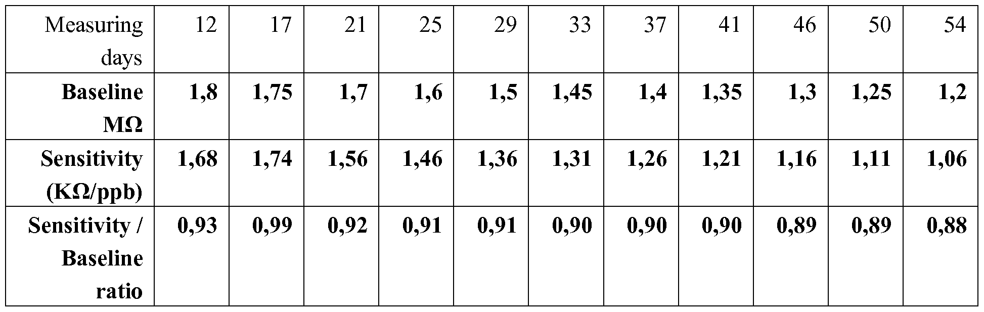
After some larger change in the first weeks, the ratio after about day 21 is substantially constant at 0.91 with a standard deviation of 0.029. The ratio (over time) can be used as predetermined relation; even, the value of 0.91 may be used as predetermined relation. When measuring (only) the baseline (drift), the sensitivity and baseline can be calibrated. In the table, the units for the ratio value have not been included for the sake of simplicity.
The term "substantially" herein, such as in "substantially consists", will be understood by the person skilled in the art. The term "substantially" may also include embodiments with "entirely", "completely", "all", etc. Hence, in
embodiments the adjective substantially may also be removed. Where applicable, the term "substantially" may also relate to 90% or higher, such as 95% or higher, especially 99%> or higher, even more especially 99.5%> or higher, including 100%. The term "comprise" includes also embodiments wherein the term "comprises" means
"consists of. The term "and/or" especially relates to one or more of the items mentioned before and after "and/or". For instance, a phrase "item 1 and/or item 2" and similar phrases may relate to one or more of item 1 and item 2. The term
"comprising" may in an embodiment refer to "consisting of but may in another embodiment also refer to "containing at least the defined species and optionally one or more other species".
Furthermore, the terms first, second, third and the like in the description and in the claims, are used for distinguishing between similar elements and not necessarily for describing a sequential or chronological order. It is to be understood that the terms so used are interchangeable under appropriate
circumstances and that the embodiments of the invention described herein are capable of operation in other sequences than described or illustrated herein.
The devices herein are amongst others described during operation. As will be clear to the person skilled in the art, the invention is not limited to methods of operation or devices in operation.
It should be noted that the above-mentioned embodiments illustrate rather than limit the invention, and that those skilled in the art will be able to design many alternative embodiments without departing from the scope of the appended claims. In the claims, any reference signs placed between parentheses shall not be construed as limiting the claim. Use of the verb "to comprise" and its conjugations does not exclude the presence of elements or steps other than those stated in a claim. The article "a" or "an" preceding an element does not exclude the presence of a plurality of such elements. The invention may be implemented by means of hardware comprising several distinct elements, and by means of a suitably programmed computer. In the device claim enumerating several means, several of these means may be embodied by one and the same item of hardware. The mere fact that certain measures are recited in mutually different dependent claims does not indicate that a combination of these measures cannot be used to advantage.
The invention further applies to a device comprising one or more of the characterizing features described in the description and/or shown in the attached
drawings. The invention further pertains to a method or process comprising one or more of the characterizing features described in the description and/or shown in the attached drawings.
The various aspects discussed in this patent can be combined in order to provide additional advantages. Further, the person skilled in the art will understand that embodiments can be combined, and that also more than two embodiments can be combined. Furthermore, some of the features can form the basis for one or more divisional applications.
Claims
1. A gas sensor device (10) comprising (a) a MOx sensor (100) with a sensor surface (110), (b) a closing element (21) and an actuator (22) configured to shield in a closed state the sensor surface (110) from ambient with a headspace (30) over the sensor surface (110), and (c) a control system (40), wherein:
the gas sensor device (10) has in operation one or more of a sensing mode and a calibration mode;
the control system (40) is configured to calibrate the MOx sensor (100) with a calibration procedure comprising:
a zero-gas value determination stage comprising providing the MOx sensor (100) at a predefined working temperature with the closing element (21) in the closed state and determining the zero-gas value;
a calibrating stage comprising calibrating the MOx sensor (100) based on (a) the zero-gas value and (b) a predetermined relation between the zero-gas value and the sensitivity of the MOx sensor (100).
2. The gas sensor device (10) according to claim 1, wherein the control system (40) is configured to execute the calibration procedure after a predetermined operation time.
3. The gas sensor device (10) according to any one of the preceding claims, wherein the control system (40) is configured to execute the calibration procedure directly after switching on the gas sensor device (10).
4. The gas sensor device (10) according to any one of the preceding claims, wherein the control system (40) is configured to execute the calibration procedure after reaching a predetermined value during the sensing mode.
5. The gas sensor device (10) according to any one of the preceding claims, wherein the control system (40) is configured to determine the zero-gas value one or more times while the gas sensor device (10) is in the sensing mode.
6. The gas sensor device (10) according to claim 5, wherein the control system (40) is configured to execute the calibration stage after reaching a zero-gas value complying with a predetermined reference value.
7. The gas sensor device (10) according to any one of the preceding claims, further comprising a gas filter (50) configure upstream of the sensor surface (110).
8. The gas sensor device (10) according to any one of the preceding claims, wherein the gas sensor device (10) is configured to execute at least part of a sensing mode period with the closing element in the closed state.
9. The gas sensor device (10) according to any one of the preceding claims, further comprising a gas flow control device (60) configured to actively sample a gas.
10. The gas sensor device (10) according to any one of the preceding claims, wherein the MOx sensor (100) comprises a Sn02 based MOx sensor, and wherein the predefined working temperature is selected from the range of 200-500 °C.
11. An air treatment device comprising the gas sensor device (10) according to any one of the preceding claims.
12. A method of operating a gas sensor device (10) comprising a MOx sensor (100) with a sensor surface (110), wherein the gas sensor device (10) has in operation one or more of a sensing mode and a calibration mode, the method comprising one or more of (i) sensing a gas with the MOx sensor (100) and (ii) calibrating the MOx sensor (100) with a calibration procedure, with the calibration procedure comprising:
determining in a determination stage a zero-gas value with the MOx sensor (100) at a predefined working temperature and with the sensor surface (110) exposed to a closed headspace (30);
calibrating the MOx sensor (100) in a calibration stage based on (a) the zero-gas value and (b) a predetermined relation between the zero-gas value and the sensitivity of the MOx sensor (100).
13. The method according to claim 12, wherein the MOx sensor (100) comprises a Sn02 based MOx sensor, and wherein the predefined working temperature is selected from the range of 200-500 °C.
14. The method according to any one of the preceding claims 12-13, the method comprising determining the zero-gas value one or more times while the gas sensor device (10) is in the sensing mode, and the method further comprising execute the calibration stage after reaching a zero-gas value complying with a predetermined reference value.
15. Use of the gas sensor device (10) according to any one of the preceding claims 1-10, for (a) correcting zero-gas level drift and/or sensitivity drift of the gas sensor device (10) according to the method according to any one of the preceding claims 12-14, and (b) for sensing volatile organic compounds.
Applications Claiming Priority (2)
| Application Number | Priority Date | Filing Date | Title |
|---|---|---|---|
| EP16172222 | 2016-05-31 | ||
| EP16172222.8 | 2016-05-31 |
Publications (1)
| Publication Number | Publication Date |
|---|---|
| WO2017207594A1 true WO2017207594A1 (en) | 2017-12-07 |
Family
ID=56117508
Family Applications (1)
| Application Number | Title | Priority Date | Filing Date |
|---|---|---|---|
| PCT/EP2017/063076 WO2017207594A1 (en) | 2016-05-31 | 2017-05-31 | Method of calibrating a mox sensor |
Country Status (1)
| Country | Link |
|---|---|
| WO (1) | WO2017207594A1 (en) |
Cited By (4)
| Publication number | Priority date | Publication date | Assignee | Title |
|---|---|---|---|---|
| CN109613184A (en) * | 2019-01-24 | 2019-04-12 | 北京雪迪龙科技股份有限公司 | A kind of gas monitoring system and gas monitoring method with zero gas inner circulation structure |
| EP3650851A1 (en) * | 2018-11-06 | 2020-05-13 | Withings | Calibration of an air quality sensor in a device |
| US11079364B2 (en) | 2018-11-06 | 2021-08-03 | Withings | Calibration of an air quality sensor in a device |
| WO2021176931A1 (en) * | 2020-03-05 | 2021-09-10 | 新東工業株式会社 | Gas measurement device |
Citations (4)
| Publication number | Priority date | Publication date | Assignee | Title |
|---|---|---|---|---|
| WO1997045189A1 (en) | 1996-05-31 | 1997-12-04 | Philips Electronics N.V. | Air filtration device |
| US6774613B1 (en) | 1999-05-31 | 2004-08-10 | Eads Deutschland Gmbh | Semiconductor gas sensor, gas sensor system and method of gas analysis |
| US20150233879A1 (en) * | 2014-02-19 | 2015-08-20 | Ino Therapeutics Llc | Systems And Methods For Compensating Long Term Sensitivity Drift Of Electrochemical Gas Sensors Exposed To Nitric Oxide |
| US20150301005A1 (en) | 2011-01-31 | 2015-10-22 | Scott Technologies, Inc. | System and Method for Automatically Adjusting Gas Sensor Settings and Parameters |
-
2017
- 2017-05-31 WO PCT/EP2017/063076 patent/WO2017207594A1/en active Application Filing
Patent Citations (4)
| Publication number | Priority date | Publication date | Assignee | Title |
|---|---|---|---|---|
| WO1997045189A1 (en) | 1996-05-31 | 1997-12-04 | Philips Electronics N.V. | Air filtration device |
| US6774613B1 (en) | 1999-05-31 | 2004-08-10 | Eads Deutschland Gmbh | Semiconductor gas sensor, gas sensor system and method of gas analysis |
| US20150301005A1 (en) | 2011-01-31 | 2015-10-22 | Scott Technologies, Inc. | System and Method for Automatically Adjusting Gas Sensor Settings and Parameters |
| US20150233879A1 (en) * | 2014-02-19 | 2015-08-20 | Ino Therapeutics Llc | Systems And Methods For Compensating Long Term Sensitivity Drift Of Electrochemical Gas Sensors Exposed To Nitric Oxide |
Cited By (6)
| Publication number | Priority date | Publication date | Assignee | Title |
|---|---|---|---|---|
| EP3650851A1 (en) * | 2018-11-06 | 2020-05-13 | Withings | Calibration of an air quality sensor in a device |
| US11079364B2 (en) | 2018-11-06 | 2021-08-03 | Withings | Calibration of an air quality sensor in a device |
| CN109613184A (en) * | 2019-01-24 | 2019-04-12 | 北京雪迪龙科技股份有限公司 | A kind of gas monitoring system and gas monitoring method with zero gas inner circulation structure |
| WO2021176931A1 (en) * | 2020-03-05 | 2021-09-10 | 新東工業株式会社 | Gas measurement device |
| JP2021139768A (en) * | 2020-03-05 | 2021-09-16 | 新東工業株式会社 | Gas measurement device |
| JP7278548B2 (en) | 2020-03-05 | 2023-05-22 | 新東工業株式会社 | gas measuring instrument |
Similar Documents
| Publication | Publication Date | Title |
|---|---|---|
| WO2017207594A1 (en) | Method of calibrating a mox sensor | |
| US6055840A (en) | Method and apparatus for determining concentration of a gas | |
| Haugen et al. | A calibration method for handling the temporal drift of solid state gas-sensors | |
| US6270651B1 (en) | Gas component sensor | |
| EP3203229B1 (en) | Calibrating a gas sensor | |
| Ryabtsev et al. | Application of semiconductor gas sensors for medical diagnostics | |
| JP4591105B2 (en) | Calibration method | |
| CA2223607C (en) | Breath testing apparatus | |
| JP2001507799A (en) | Humidity sensor for detecting differential heat and detection method | |
| US20060042353A1 (en) | Analyte quantitation using semiconducting metal oxide gas sensors | |
| JP7399275B2 (en) | How to operate and calibrate gas sensors and related gas sensors | |
| JP2007248356A (en) | Flammable gas detector and flammable gas detecting method | |
| US9222911B2 (en) | Method and device for detecting at least one property of a gas | |
| EP2581738B1 (en) | Calibration technique for calibrating a zirconium oxide oxygen sensor and calibrated sensor | |
| CN109142642A (en) | A kind of gas concentration quick sensing device and cognitive method | |
| Wu et al. | Odor-based incontinence sensor | |
| Welles | A portable photosynthesis system | |
| JP4175767B2 (en) | Gas analyzer and calibration method thereof | |
| JP2893086B2 (en) | Control method of atmosphere in culture chamber in incubator | |
| Song et al. | A micro hot-wire sensors for gas sensing applications | |
| US20080208503A1 (en) | Method and device for compensating temperature dependencies | |
| US11927514B2 (en) | Method and device for calibrating a fluid detector having a preconcentrator | |
| Gajdošík | The derivation of the electrical conductance/concentration dependency for SnO2 gas sensor for ethanol | |
| Tobaly | An apparatus for vapor pressure measurements of organic solids using a computer controlled null‐detector | |
| JP3554464B2 (en) | Chamber used for low concentration NOx measuring instrument |
Legal Events
| Date | Code | Title | Description |
|---|---|---|---|
| 121 | Ep: the epo has been informed by wipo that ep was designated in this application |
Ref document number: 17727855 Country of ref document: EP Kind code of ref document: A1 |
|
| NENP | Non-entry into the national phase |
Ref country code: DE |
|
| 122 | Ep: pct application non-entry in european phase |
Ref document number: 17727855 Country of ref document: EP Kind code of ref document: A1 |