WO2017206487A1 - 防风噪麦克风以及耳机线控装置 - Google Patents
防风噪麦克风以及耳机线控装置 Download PDFInfo
- Publication number
- WO2017206487A1 WO2017206487A1 PCT/CN2016/110765 CN2016110765W WO2017206487A1 WO 2017206487 A1 WO2017206487 A1 WO 2017206487A1 CN 2016110765 W CN2016110765 W CN 2016110765W WO 2017206487 A1 WO2017206487 A1 WO 2017206487A1
- Authority
- WO
- WIPO (PCT)
- Prior art keywords
- microphone
- sound
- wind noise
- sound channel
- side wall
- Prior art date
- Legal status (The legal status is an assumption and is not a legal conclusion. Google has not performed a legal analysis and makes no representation as to the accuracy of the status listed.)
- Ceased
Links
Images




Classifications
-
- H—ELECTRICITY
- H04—ELECTRIC COMMUNICATION TECHNIQUE
- H04R—LOUDSPEAKERS, MICROPHONES, GRAMOPHONE PICK-UPS OR LIKE ACOUSTIC ELECTROMECHANICAL TRANSDUCERS; ELECTRIC HEARING AIDS; PUBLIC ADDRESS SYSTEMS
- H04R1/00—Details of transducers, loudspeakers or microphones
- H04R1/08—Mouthpieces; Microphones; Attachments therefor
- H04R1/083—Special constructions of mouthpieces
-
- H—ELECTRICITY
- H04—ELECTRIC COMMUNICATION TECHNIQUE
- H04R—LOUDSPEAKERS, MICROPHONES, GRAMOPHONE PICK-UPS OR LIKE ACOUSTIC ELECTROMECHANICAL TRANSDUCERS; ELECTRIC HEARING AIDS; PUBLIC ADDRESS SYSTEMS
- H04R1/00—Details of transducers, loudspeakers or microphones
- H04R1/08—Mouthpieces; Microphones; Attachments therefor
-
- H—ELECTRICITY
- H04—ELECTRIC COMMUNICATION TECHNIQUE
- H04R—LOUDSPEAKERS, MICROPHONES, GRAMOPHONE PICK-UPS OR LIKE ACOUSTIC ELECTROMECHANICAL TRANSDUCERS; ELECTRIC HEARING AIDS; PUBLIC ADDRESS SYSTEMS
- H04R1/00—Details of transducers, loudspeakers or microphones
- H04R1/10—Earpieces; Attachments therefor ; Earphones; Monophonic headphones
-
- H—ELECTRICITY
- H04—ELECTRIC COMMUNICATION TECHNIQUE
- H04R—LOUDSPEAKERS, MICROPHONES, GRAMOPHONE PICK-UPS OR LIKE ACOUSTIC ELECTROMECHANICAL TRANSDUCERS; ELECTRIC HEARING AIDS; PUBLIC ADDRESS SYSTEMS
- H04R1/00—Details of transducers, loudspeakers or microphones
- H04R1/10—Earpieces; Attachments therefor ; Earphones; Monophonic headphones
- H04R1/1033—Cables or cables storage, e.g. cable reels
-
- H—ELECTRICITY
- H04—ELECTRIC COMMUNICATION TECHNIQUE
- H04R—LOUDSPEAKERS, MICROPHONES, GRAMOPHONE PICK-UPS OR LIKE ACOUSTIC ELECTROMECHANICAL TRANSDUCERS; ELECTRIC HEARING AIDS; PUBLIC ADDRESS SYSTEMS
- H04R1/00—Details of transducers, loudspeakers or microphones
- H04R1/10—Earpieces; Attachments therefor ; Earphones; Monophonic headphones
- H04R1/1041—Mechanical or electronic switches, or control elements
-
- H—ELECTRICITY
- H04—ELECTRIC COMMUNICATION TECHNIQUE
- H04R—LOUDSPEAKERS, MICROPHONES, GRAMOPHONE PICK-UPS OR LIKE ACOUSTIC ELECTROMECHANICAL TRANSDUCERS; ELECTRIC HEARING AIDS; PUBLIC ADDRESS SYSTEMS
- H04R1/00—Details of transducers, loudspeakers or microphones
- H04R1/10—Earpieces; Attachments therefor ; Earphones; Monophonic headphones
- H04R1/1083—Reduction of ambient noise
-
- B—PERFORMING OPERATIONS; TRANSPORTING
- B81—MICROSTRUCTURAL TECHNOLOGY
- B81B—MICROSTRUCTURAL DEVICES OR SYSTEMS, e.g. MICROMECHANICAL DEVICES
- B81B2201/00—Specific applications of microelectromechanical systems
- B81B2201/02—Sensors
- B81B2201/0257—Microphones or microspeakers
-
- H—ELECTRICITY
- H04—ELECTRIC COMMUNICATION TECHNIQUE
- H04R—LOUDSPEAKERS, MICROPHONES, GRAMOPHONE PICK-UPS OR LIKE ACOUSTIC ELECTROMECHANICAL TRANSDUCERS; ELECTRIC HEARING AIDS; PUBLIC ADDRESS SYSTEMS
- H04R1/00—Details of transducers, loudspeakers or microphones
- H04R1/02—Casings; Cabinets ; Supports therefor; Mountings therein
- H04R1/028—Casings; Cabinets ; Supports therefor; Mountings therein associated with devices performing functions other than acoustics, e.g. electric candles
-
- H—ELECTRICITY
- H04—ELECTRIC COMMUNICATION TECHNIQUE
- H04R—LOUDSPEAKERS, MICROPHONES, GRAMOPHONE PICK-UPS OR LIKE ACOUSTIC ELECTROMECHANICAL TRANSDUCERS; ELECTRIC HEARING AIDS; PUBLIC ADDRESS SYSTEMS
- H04R1/00—Details of transducers, loudspeakers or microphones
- H04R1/20—Arrangements for obtaining desired frequency or directional characteristics
- H04R1/32—Arrangements for obtaining desired frequency or directional characteristics for obtaining desired directional characteristic only
- H04R1/34—Arrangements for obtaining desired frequency or directional characteristics for obtaining desired directional characteristic only by using a single transducer with sound reflecting, diffracting, directing or guiding means
- H04R1/342—Arrangements for obtaining desired frequency or directional characteristics for obtaining desired directional characteristic only by using a single transducer with sound reflecting, diffracting, directing or guiding means for microphones
-
- H—ELECTRICITY
- H04—ELECTRIC COMMUNICATION TECHNIQUE
- H04R—LOUDSPEAKERS, MICROPHONES, GRAMOPHONE PICK-UPS OR LIKE ACOUSTIC ELECTROMECHANICAL TRANSDUCERS; ELECTRIC HEARING AIDS; PUBLIC ADDRESS SYSTEMS
- H04R2201/00—Details of transducers, loudspeakers or microphones covered by H04R1/00 but not provided for in any of its subgroups
- H04R2201/10—Details of earpieces, attachments therefor, earphones or monophonic headphones covered by H04R1/10 but not provided for in any of its subgroups
- H04R2201/107—Monophonic and stereophonic headphones with microphone for two-way hands free communication
-
- H—ELECTRICITY
- H04—ELECTRIC COMMUNICATION TECHNIQUE
- H04R—LOUDSPEAKERS, MICROPHONES, GRAMOPHONE PICK-UPS OR LIKE ACOUSTIC ELECTROMECHANICAL TRANSDUCERS; ELECTRIC HEARING AIDS; PUBLIC ADDRESS SYSTEMS
- H04R2410/00—Microphones
- H04R2410/07—Mechanical or electrical reduction of wind noise generated by wind passing a microphone
-
- H—ELECTRICITY
- H04—ELECTRIC COMMUNICATION TECHNIQUE
- H04R—LOUDSPEAKERS, MICROPHONES, GRAMOPHONE PICK-UPS OR LIKE ACOUSTIC ELECTROMECHANICAL TRANSDUCERS; ELECTRIC HEARING AIDS; PUBLIC ADDRESS SYSTEMS
- H04R2460/00—Details of hearing devices, i.e. of ear- or headphones covered by H04R1/10 or H04R5/033 but not provided for in any of their subgroups, or of hearing aids covered by H04R25/00 but not provided for in any of its subgroups
- H04R2460/01—Hearing devices using active noise cancellation
Definitions
- the present invention relates to the field of acoustic energy conversion technology, and more particularly to a wind noise prevention microphone and a headphone wire control device to which the microphone is applied.
- Existing microphones are prone to wind noise when used, especially when used outdoors. Wind noise is generated by the action of the wind blowing into the sound of the voice device and the turbulence generated by the friction of the sound channel and the microphone pickup hole.
- Existing voice devices such as the microphone of the control box, are more prone to wind noise because the microphone elements are disposed opposite to the sound entrance holes of the housing.
- An object of the present invention is to provide a new technical solution for a wind noise prevention microphone and a headphone wire control device.
- a wind noise resistant microphone includes:
- a microphone cavity formed by the bottom and the first side wall
- a microphone unit disposed in the microphone cavity, a sound collecting hole of the microphone unit is disposed opposite to the bottom, and a predetermined spacing is formed between the sound collecting hole and the bottom;
- the first side wall is perpendicular to the bottom and the sound channel is opposite the gap between the sound collecting hole and the bottom.
- the sound channel is linear, curved or wavy.
- a spoiler protruding from the inner wall of the sound channel and interlaced with each other is disposed in the sound channel.
- the sound channel has a circular, rectangular, semi-circular, trapezoidal or triangular cross section.
- the sound channel is filled with foam or sponge.
- the microphone unit is an electret microphone or a microelectromechanical microphone.
- a headphone wire control device includes: a housing having a device cavity, an audio processing device, and the above-described wind noise microphone, the wind noise microphone and the audio processing device being disposed within the device cavity, and the wind noise microphone and the audio
- the processing device is signally connected, one end of the sound channel is passed out from the first side wall, and the other end of the sound channel is passed out from the shell wall of the housing to form a receiving hole.
- the other end of the sound channel exits from the second side wall of the housing.
- the housing, the bottom, the first side wall, and the sound channel are integrally formed.
- the inventors of the present invention have found that in the prior art, the sound collecting hole of the microphone is disposed opposite to the sound channel of the voice device, and the structure is prone to generate wind noise and affect the sound picking effect. Therefore, the technical task to be achieved by the present invention or the technical problem to be solved is not thought of or expected by those skilled in the art, so the present invention is a new technical solution.
- the wind noise microphone provided by the invention has a sound channel disposed at a side of the sound collecting hole of the microphone, instead of directly facing the sound collecting hole of the microphone, and can effectively reduce wind noise. Improve the quality of sound pickup.
- the earphone wire control device is provided with the above-mentioned wind noise noise microphone, and has the characteristics of good sound effect.
- FIG. 1 is a schematic structural view of a microphone cavity and a sound channel according to an embodiment of the present invention.
- FIG. 2 is a schematic structural diagram of a voice device without a microphone unit according to an embodiment of the present invention.
- Figure 3 View of another angle of Figure 2.
- FIG. 4 is a schematic structural diagram of a voice device with a wind noise prevention microphone according to an embodiment of the present invention.
- Figure 5 is an exploded view of a speech device with a wind noise resistant microphone in accordance with an embodiment of the present invention.
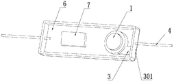
- FIG. 6 is a schematic structural diagram of a headphone wire control device according to an embodiment of the present invention.
- FIG. 7 is a schematic structural diagram of a sound channel according to an embodiment of the present invention.
- FIG. 8 is a schematic structural diagram of another sound channel according to an embodiment of the present invention.
- FIG. 9 is a schematic structural view of a third sound channel according to an embodiment of the present invention.
- FIG. 10 is a schematic structural diagram of a fourth sound channel according to an embodiment of the present invention.
- 1 microphone unit; 101: pickup hole; 2: microphone cavity; 201: first side wall; 202: bottom; 3: sound channel; 301: receiving hole; 302: spoiler; Wire; 5: foam; 6: housing; 601: second side wall; 7: audio processing device.
- the present invention provides a wind noise preventing microphone.
- the wind noise microphone can be applied to, but not limited to, a mobile phone, a computer, a smart watch, an intelligent control box, a walkie-talkie, a fixed telephone, and the like.
- the microphone includes a microphone cavity 2, a microphone unit 1 and a sound channel 3.
- the microphone cavity 2 is surrounded by a bottom portion 202 and a first side wall 201, and the microphone cavity 2 is a closed cavity.
- the shape of the microphone cavity 2 depends on the outer shape of the microphone unit 1.
- the microphone unit 1 can be, but is not limited to, a moving coil microphone, a moving iron microphone, an electret microphone (ECM), and a microelectromechanical microphone (MEMS).
- ECM microphones and MEMS microphones are small, flat and thin, especially suitable for use in electronic equipment.
- the ECM microphone has a circular sheet shape
- the MEMS microphone has a square sheet shape
- the microphone cavity 2 should be adapted to the contour of the microphone unit 1.
- the sound collecting hole 101 of the microphone unit 1 is disposed opposite to the bottom portion 202, and a pitch is set between the sound collecting hole 101 and the bottom portion 202 to provide a space for sound to enter.
- the sound channel 3 is used to connect the sound collecting hole 101 with the external space.
- the sound channel 3 is arranged to pass out from the first side wall 201. More preferably, as shown in FIG. 3, the first side wall 201 is perpendicular to the bottom portion 202, and the sound passage 3 is opposed to the gap between the sound collecting hole 101 and the bottom portion 202.
- the externally entering wind is parallel to the sound collecting hole 101, further reducing the wind noise.
- the sound channel 3 can be secured to the bottom portion 202 by techniques well known in the art, such as double-sided adhesive bonding, glue bonding, and the like.
- the sound passage 3 may be opened directly on the first side wall 201 without providing the sound passage 3.
- the sound channel 3 of the wind noise preventing microphone is disposed at the side of the sound collecting hole 101 of the microphone.
- the wind in the external environment is prevented from directly blowing into the sound collecting hole 101, and the wind noise can be effectively reduced. Improve the quality of sound pickup.
- the material of the bottom portion 202, the first side wall 201 and the sound channel 3 of the wind noise prevention microphone structure may be, but not limited to, plastic, silicone, rubber or thermoplastic elastomer (TPE). Preferably, it can be integrally molded by injection molding.
- the length of the sound channel 3 can be set according to actual needs. The larger the length, the better the wind noise prevention effect, but the greater the acoustic resistance encountered when the sound propagates, the greater the distortion of the sound; conversely, the smaller the length, the less obvious the wind noise prevention effect.
- the sound channel 3 It can be, but is not limited to, a straight line, an arc shape, or a wavy line shape. Among them, the linear sound channel 3 has a simple structure and is convenient to manufacture.
- the curved and wavy linear sound channel 3 can increase the flow distance of the wind within a limited length, and the sound resistance of the sound channel 3 is large, which can effectively reduce the speed after the wind enters, and the wind noise prevention effect is better.
- a spoiler 302 that protrudes from the inner wall of the sound passage 3 and is interlaced with each other is disposed in the sound passage 3.
- the turbulence, 302 arrangement both extends the flow path of the wind and effectively reduces the wind speed through the blockage of the spoiler 302. This structure can further reduce wind noise.
- the cross section of the sound channel 3 can be selected according to actual needs, and is not limited to a circle, a rectangle, a semicircle, a trapezoid or a triangle.
- the cross-sectional area of the sound channel 3 has a great influence on the wind noise prevention effect. The larger the cross-sectional area, the larger the amount of wind entering from the external space, and the greater the wind noise. Conversely, the smaller the cross-sectional area, the smaller the amount of wind entering. The smaller the wind noise, the greater the distortion of the sound.
- the sound channel 3 is filled with a foam 5 or a sponge.
- Foam 5 or sponge is a porous structure with a large specific surface area and a very large fiber structure, which can effectively reduce the wind speed entering the wind and absorb wind noise.
- the foam 5 or the sponge can effectively prevent foreign matter such as dust from entering, and reduce the sound distortion caused by the entry of impurities.
- the present invention also provides a headphone wire control device, as shown in Figures 2-6, comprising: a housing 6 having a device cavity, an audio processing device 7, and a wind noise microphone provided by the present invention.
- the wind noise prevention microphone and the audio processing device 7 are disposed in the device cavity and are electrically or signally connected to the external device through the wires 4.
- the housing wall of the housing 6 can be utilized as the bottom 202 of the wind noise mic microphone, and the first side wall 201 is disposed on the housing wall to form a microphone device cavity.
- the wind noise microphone is signally connected to the audio processing device 7, and the signal connection between the two can be realized through the PCB board.
- the audio processing device is configured to process the audio received by the microphone.
- the audio processing device directly converts the received sound signal into a transmittable audio signal, and transmits the audio signal to other audio devices to implement the function of audio transmission.
- the audio processing device further includes a code library and a transmitting device, and the device can compare the received sound signal with a keyword pre-stored in the code library, and output the comparison result to implement voice control.
- the material of the bottom portion 202, the first side wall 201, the sound channel 3, and the like of the casing 6 and the wind noise noise microphone may be, but not limited to, plastic, silica gel, rubber or thermoplastic elastomer (TPE). When it is made, it can be integrally molded by injection molding.
- the earphone wire control device adopts a windproof noise microphone, which conforms to the development trend of thinning and thinning of electronic devices.
- the receiving hole 301 of the wind noise microphone can be opened at the side of the earphone wire control device as needed, and in some examples, as shown in FIG. 6, the other end of the sound channel 3 is formed from the second side wall 601 of the casing 6.
- the hole 301 is received.
- the position at which the receiving hole 301 is disposed may not be limited by the position of the sound collecting hole 101 of the microphone.
- the earphone wire control device has the characteristics of small wind noise and good sound effect.
Landscapes
- Physics & Mathematics (AREA)
- Engineering & Computer Science (AREA)
- Acoustics & Sound (AREA)
- Signal Processing (AREA)
- Soundproofing, Sound Blocking, And Sound Damping (AREA)
- Details Of Audible-Bandwidth Transducers (AREA)
Abstract
本发明公开了一种防风噪麦克风以及耳机线控装置。该麦克风包括:由底部和第一侧壁包围形成的麦克风腔体;设置在所述麦克风腔体内的麦克风单体,所述麦克风单体的拾音孔与所述底部相对设置,并且所述拾音孔与所述底部之间具有设定的间距;以及连通所述拾音孔与外部空间的声音通道,所述声音通道从所述第一侧壁穿出。该麦克风的声音通道设置在麦克风的拾音孔的侧部,而不是直接与麦克风的拾音孔相对,可以有效地减小风噪。提高了声音拾取的质量。
Description
本发明涉及声能转换技术领域,更具体地,涉及一种防风噪麦克风以及应用了该麦克风的耳机线控装置。
现有的麦克风,使用时容易产生风噪,尤其在户外使用时。风噪是由风吹到语音设备的声音入孔,并与声音通道以及麦克风拾音孔摩擦产生的湍流的作用而产生的。现有的语音设备,如控制盒的麦克风,由于麦克风元件与壳体的声音入孔相对设置,较容易产生风噪。
发明内容
本发明的一个目的是提供一种防风噪麦克风以及耳机线控装置的新技术方案。
根据本发明的第一方面,提供了一种防风噪麦克风。该麦克风包括:
由底部和第一侧壁包围形成的麦克风腔体;
设置在所述麦克风腔体内的麦克风单体,所述麦克风单体的拾音孔与所述底部相对设置,并且所述拾音孔与所述底部之间具有设定的间距;以及
连通所述拾音孔与外部空间的声音通道,所述声音通道从所述第一侧壁穿出。
在一种实施方式中,所述第一侧壁与所述底部垂直,并且所述声音通道与所述拾音孔和所述底部之间的间隙相对。
在一种实施方式中,所述声音通道为直线形、弧线形或者波浪线形。
在一种实施方式中,所述声音通道内设置有凸出于所述声音通道的内壁且相互交错的扰流板。
在一种实施方式中,所述声音通道的横截面为圆形、矩形、半圆形、梯形或者三角形。
在一种实施方式中,所述声音通道内填充有泡棉或者海绵。
在一种实施方式中,所述麦克风单体为驻极体麦克风或者微机电麦克风。
根据本发明的另一方面提供一种耳机线控装置。该装置包括:具有装置腔体的壳体、音频处理装置和上述防风噪麦克风,所述防风噪麦克风和所述音频处理装置设置在所述装置腔体内,并且所述防风噪麦克风与所述音频处理装置信号连接,所述声音通道的一端从所述第一侧壁穿出,且所述声音通道的另一端从所述壳体的壳壁穿出形成接收孔。
在一种实施方式中,所述声音通道的另一端从所述壳体的第二侧壁穿出。
在一种实施方式中,所述壳体、所述底部、所述第一侧壁以及所述声音通道一体成型。
本发明的发明人发现,在现有技术中,麦克风的拾音孔与语音设备的声音通道相对设置,该结构容易产生风噪,影响声音的拾取效果。因此,本发明所要实现的技术任务或者所要解决的技术问题是本领域技术人员从未想到的或者没有预期到的,故本发明是一种新的技术方案。
本发明提供的防风噪麦克风,声音通道设置在麦克风的拾音孔的侧部,而不是直接与麦克风的拾音孔相对,可以有效地减小风噪。提高了声音拾取的质量。
此外,在声音通道内设置泡棉或者海绵可以更有效的减小风噪。
此外,该耳机线控装置设置有上述防风噪麦克风,具有声音效果好的特点。
通过以下参照附图对本发明的示例性实施例的详细描述,本发明的其它特征及其优点将会变得清楚。
被结合在说明书中并构成说明书的一部分的附图示出了本发明的实
施例,并且连同其说明一起用于解释本发明的原理。
图1:本发明实施例的麦克风腔体以及声音通道的结构示意图。
图2:本发明实施例的未设置麦克风单体的语音设备的结构示意图。
图3:图2另一个角度的视图。
图4:本发明实施例的具有防风噪麦克风的语音设备的结构示意图。
图5:本发明实施例的具有防风噪麦克风的语音设备的分解图。
图6:本发明实施例的耳机线控装置的结构示意图。
图7:本发明实施例的声音通道的结构示意图。
图8:本发明实施例的另一种声音通道的结构示意图。
图9:本发明实施例的第三种声音通道的结构示意图。
图10:本发明实施例的第四种声音通道的结构示意图。
图中,1:麦克风单体;101:拾音孔;2:麦克风腔体;201:第一侧壁;202:底部;3:声音通道;301:接收孔;302:扰流板;4:导线;5:泡棉;6:壳体;601:第二侧壁;7:音频处理装置。
现在将参照附图来详细描述本发明的各种示例性实施例。应注意到:除非另外具体说明,否则在这些实施例中阐述的部件和步骤的相对布置、数字表达式和数值不限制本发明的范围。
以下对至少一个示例性实施例的描述实际上仅仅是说明性的,决不作为对本发明及其应用或使用的任何限制。
对于相关领域普通技术人员已知的技术、方法和设备可能不作详细讨论,但在适当情况下,所述技术、方法和设备应当被视为说明书的一部分。
在这里示出和讨论的所有例子中,任何具体值应被解释为仅仅是示例性的,而不是作为限制。因此,示例性实施例的其它例子可以具有不同的值。
应注意到:相似的标号和字母在下面的附图中表示类似项,因此,一旦某一项在一个附图中被定义,则在随后的附图中不需要对其进行进一步讨论。
为了至少解决上述问题之一。本发明提供了一种防风噪麦克风。该防风噪麦克风可以应用在但不局限于手机、电脑、智能手表、智能控制盒、对讲机、固定电话机等语音设备中。如图1所示,该麦克风包括:麦克风腔体2、麦克风单体1和声音通道3。麦克风腔体2由底部202和第一侧壁201包围而成,麦克风腔体2为一个封闭腔。麦克风腔体2的形状根据麦克风单体1的外形结构而定。麦克风单体1可以是但不局限于动圈式麦克风、动铁式麦克风、驻极体麦克风(ECM)和微机电麦克风(MEMS)。其中,ECM麦克风和MEMS麦克风具有体积小、扁平化并且轻薄的特点,尤其适用于电子设备中。通常情况下,ECM麦克风为圆形片状,MEMS麦克风为方形片状,则麦克风腔体2应适应麦克风单体1的轮廓。
如图4-6所示,麦克风单体1的拾音孔101与底部202相对设置,并且拾音孔101与底部202之间具有设定的间距,以提供声音进入的空间。声音通道3用于连通拾音孔101与外部空间。在本发明实施例中,声音通道3被设置为从第一侧壁201穿出。更加优选的是,如图3所示,第一侧壁201与底部202相垂直,并且声音通道3与拾音孔101和底部202之间的间隙相对。这样外部进入的风与拾音孔101平行,进一步降低了风噪。可以通过本领域所熟知的技术手段,如双面胶粘接、胶水粘接等方式将声音通道3固定在底部202上。当然,如果第一侧壁201具有足够的厚度,该厚度足以使声音沿侧壁的厚度方向进入,则可以不设置声音通道3,直接在第一侧壁201上开设声音通道3。
该防风噪麦克风的声音通道3设置在麦克风的拾音孔101的侧部。避免了外界环境中的风直接吹到拾音孔101中,可以有效地减小风噪。提高了声音拾取的质量。
在本发明的一种具体的实施方式中,防风噪麦克风结构的底部202、第一侧壁201和声音通道3的材质可以是但不局限于塑料、硅胶、橡胶或者热塑性弹性体(TPE)。优选的是,可以采用注塑成型的方式一体成型。
需要说明的是,声音通道3的长度可以根据实际需要进行设置。长度越大则防风噪效果越好,但是声音传播时遇到的声阻也越大,声音失真越大;反之,长度越小则防风噪效果越不明显。如图7-9所示,声音通道3
可以是但不局限于直线形、弧线形或者波浪线形。其中,直线形的声音通道3结构简单,制作方便。弧线形和波浪线形的声音通道3可以使在有限的长度内风的流动距离增大,进而声音通道3的声阻大,可以有效地降低风进入后的速度,防风噪效果更好。在另一些示例中,如图10所示,声音通道3内设置有凸出与声音通道3的内壁且相互交错的扰流板302。扰流,302的设置既延长了风的流动路径,又能通过扰流板302的阻挡有效地降低风速。这种结构可以进一步降低风噪。
声音通道3的横截面可以根据实际需要进行选择,不局限于圆形、矩形、半圆形、梯形或者三角形。声音通道3的截面积对防风噪效果影响较大,截面积越大则从外部空间进入的风的量越大,风噪会越大;反之,截面积越小则进入的风的量越小,风噪越小,但声音的失真会越大。
为了进一步提高防风噪的效果,在本发明的一种具体的实施方式中,如图5所示,在声音通道3内填充有泡棉5或者海绵。泡棉5或者海绵为多孔结构,具有大的比表面积和非常多的纤维结构,可以有效地降低进入风的风速,并且可以吸收风噪。此外,泡棉5或者海绵还可以有效地阻止外界的灰尘等杂质进入,降低了因杂质进入导致的声音失真。
本发明还提供一种耳机线控装置,如图2-6所示,该装置包括:具有装置腔体的壳体6、音频处理装置7和本发明提供的防风噪麦克风。其中,防风噪麦克风和音频处理装置7设置在装置腔体内,并且通过导线4与外部设备电连接或者信号连接。可以利用壳体6的壳壁作为防风噪麦克风的底部202,在壳壁上设置第一侧壁201形成麦克风装置腔体。防风噪麦克风与音频处理装置7信号连接,可以通过PCB板实现二者之间的信号连接。声音通道3的一端从第一侧壁201穿出,并且声音通道3的另一端从壳体6的壳壁穿出形成接收孔301。音频处理设备用于处理麦克风接收的音频,在一些示例中,音频处理设备将接收到的声音信号直接转换为可发送的音频信号,将该音频信号发送到其他音频设备,实现音频传输的功能。在另一些示例中,音频处理设备还包括码库和发送装置,该设备可以将接收到的声音信号与码库中预存的关键词进行比对,并将比对结果输出,以实现语音控制的功能。
需要说明的是,壳体6以及防风噪麦克风的底部202、第一侧壁201、声音通道3等的材质可以是但不局限于塑料、硅胶、橡胶或者热塑性弹性体(TPE)。制作时,可以采用注塑成型的方式一体成型。
该耳机线控装置的采用防风噪麦克风,顺应了电子设备轻薄化的发展趋势。防风噪麦克风的接收孔301可以根据需要开设在耳机线控装置的侧部,在一些示例中,如图6所示,声音通道3的另一端从壳体6的第二侧壁601穿出形成接收孔301。接收孔301的设置位置可以不受麦克风的拾音孔101的位置的限制。该耳机线控装置具有风噪小、声音效果好的特点。
虽然已经通过例子对本发明的一些特定实施例进行了详细说明,但是本领域的技术人员应该理解,以上例子仅是为了进行说明,而不是为了限制本发明的范围。本领域的技术人员应该理解,可在不脱离本发明的范围和精神的情况下,对以上实施例进行修改。本发明的范围由所附权利要求来限定。
Claims (10)
- 一种防风噪麦克风,其特征在于,包括:由底部(202)和第一侧壁(201)包围形成的麦克风腔体(2);设置在所述麦克风腔体(2)内的麦克风单体(1),所述麦克风单体(1)的拾音孔(101)与所述底部(202)相对设置,并且所述拾音孔(101)与所述底部(202)之间具有设定的间距;以及连通所述拾音孔(101)与外部空间的声音通道(3),所述声音通道(3)从所述第一侧壁(201)穿出。
- 根据权利要求1所述的防风噪麦克风,其特征在于,所述第一侧壁(201)与所述底部(202)垂直,并且所述声音通道(3)与所述拾音孔(101)和所述底部(202)之间的间隙相对。
- 根据权利要求2或者3所述的防风噪麦克风,其特征在于,所述声音通道(3)为直线形、弧线形或者波浪线形。
- 根据权利要求1-3中的任意一项所述的防风噪麦克风,其特征在于,所述声音通道(3)内设置有凸出于所述声音通道(3)的内壁且相互交错的扰流板(302)。
- 根据权利要求1-4中的任意一项所述的防风噪麦克风,其特征在于,所述声音通道(3)的横截面为圆形、矩形、半圆形、梯形或者三角形。
- 根据权利要求1-5中的任意一项所述的防风噪麦克风,其特征在于,所述声音通道(3)内填充有泡棉(5)或者海绵。
- 根据权利要求1-6中的任意一项所述的防风噪麦克风,其特征在于,所述麦克风单体(1)为驻极体麦克风或者微机电麦克风。
- 一种耳机线控装置,其特征在于,包括:具有装置腔体的壳体(6)、音频处理装置(7)和如权利要求1-7中的任意一项所述的防风噪麦克风,所述防风噪麦克风和所述音频处理装置(7)设置在所述装置腔体内,并且所述防风噪麦克风与所述音频处理装置(7)信号连接,所述声音通道(3)的一端从所述第一侧壁(201)穿出,且所述声音通道(3)的另一端从所述壳体(6)的壳壁穿出形成接收孔(301)。
- 根据权利要求8所述的耳机线控装置,其特征在于,所述声音通道(3)的另一端从所述壳体(6)的第二侧壁(601)穿出。
- 根据权利要求8或者9所述的耳机线控装置,其特征在于,所述壳体(6)、所述底部(202)、所述第一侧壁(201)以及所述声音通道(3)一体成型。
Priority Applications (1)
| Application Number | Priority Date | Filing Date | Title |
|---|---|---|---|
| US16/304,559 US10715899B2 (en) | 2016-05-30 | 2016-12-19 | Wind noise prevention microphone and earphone cable control apparatus |
Applications Claiming Priority (2)
| Application Number | Priority Date | Filing Date | Title |
|---|---|---|---|
| CN201610375376.X | 2016-05-30 | ||
| CN201610375376.XA CN105959837B (zh) | 2016-05-30 | 2016-05-30 | 防风噪麦克风以及耳机线控装置 |
Publications (1)
| Publication Number | Publication Date |
|---|---|
| WO2017206487A1 true WO2017206487A1 (zh) | 2017-12-07 |
Family
ID=56907366
Family Applications (1)
| Application Number | Title | Priority Date | Filing Date |
|---|---|---|---|
| PCT/CN2016/110765 Ceased WO2017206487A1 (zh) | 2016-05-30 | 2016-12-19 | 防风噪麦克风以及耳机线控装置 |
Country Status (3)
| Country | Link |
|---|---|
| US (1) | US10715899B2 (zh) |
| CN (1) | CN105959837B (zh) |
| WO (1) | WO2017206487A1 (zh) |
Cited By (2)
| Publication number | Priority date | Publication date | Assignee | Title |
|---|---|---|---|---|
| CN111866650A (zh) * | 2020-08-19 | 2020-10-30 | 深圳市大十科技有限公司 | 一种防风噪的耳机装置 |
| CN118450292A (zh) * | 2023-09-14 | 2024-08-06 | 荣耀终端有限公司 | 一种麦克风模组及电子设备 |
Families Citing this family (17)
| Publication number | Priority date | Publication date | Assignee | Title |
|---|---|---|---|---|
| CN105959837B (zh) | 2016-05-30 | 2020-01-03 | 歌尔股份有限公司 | 防风噪麦克风以及耳机线控装置 |
| CN107493526B (zh) * | 2016-11-15 | 2023-08-15 | 北京酷智科技有限公司 | 一种拾音设备和耳麦 |
| CN106851446A (zh) * | 2017-02-28 | 2017-06-13 | 歌尔股份有限公司 | 麦克风防风噪装置以及电子设备 |
| CN106878839B (zh) * | 2017-02-28 | 2019-08-16 | 歌尔股份有限公司 | 麦克风防风噪装置以及电子设备 |
| WO2019127290A1 (zh) * | 2017-12-28 | 2019-07-04 | 海能达通信股份有限公司 | 通讯设备的防风噪装置及通讯设备 |
| CN108632694B (zh) * | 2018-08-16 | 2024-04-02 | 歌尔科技有限公司 | 一种可衰减麦克风风噪的电子产品 |
| CN112205001A (zh) * | 2019-09-27 | 2021-01-08 | 深圳市大疆创新科技有限公司 | 声音采集方法、声音采集结构及无人机 |
| CN110856076A (zh) * | 2019-12-25 | 2020-02-28 | 歌尔科技有限公司 | 一种防风噪耳机 |
| CN111107455B (zh) * | 2019-12-27 | 2021-07-13 | 思必驰科技股份有限公司 | 用于智能语音设备的防风处理方法、防风结构及具有该结构的智能语音设备 |
| CN111770405B (zh) * | 2020-06-15 | 2024-07-26 | 江西联创宏声电子股份有限公司 | 一种耳机 |
| CN111818435B (zh) * | 2020-06-24 | 2021-07-06 | 宁波工程学院 | 一种骨传导智能助听器 |
| CN214101705U (zh) * | 2020-09-02 | 2021-08-31 | 华为技术有限公司 | 防风噪耳机 |
| CN114649666A (zh) * | 2020-12-17 | 2022-06-21 | Oppo(重庆)智能科技有限公司 | 电子装置 |
| CN114827799B (zh) * | 2021-01-28 | 2025-03-04 | 镇江贝斯特新材料股份有限公司 | 降低风噪的电子装置及其应用 |
| CN115134695B (zh) * | 2021-03-24 | 2024-07-05 | 华为技术有限公司 | 用于传声器的拾音结构及电子终端设备 |
| CN114286215B (zh) * | 2021-11-09 | 2025-08-08 | 河源源丰电子有限公司 | 一种应用于外露式通讯耳机的防风噪麦克风收音结构 |
| CN115996341B (zh) * | 2023-03-23 | 2023-09-19 | 荣耀终端有限公司 | 降噪结构、拾音组件及电子设备 |
Citations (5)
| Publication number | Priority date | Publication date | Assignee | Title |
|---|---|---|---|---|
| US20070003090A1 (en) * | 2003-06-06 | 2007-01-04 | David Anderson | Wind noise reduction for microphone |
| CN102404656A (zh) * | 2010-09-16 | 2012-04-04 | 潍坊歌尔电子有限公司 | 盲孔式麦克风 |
| CN202617317U (zh) * | 2012-05-09 | 2012-12-19 | 中兴通讯股份有限公司 | 一种麦克装置 |
| CN202931519U (zh) * | 2012-11-08 | 2013-05-08 | 山东共达电声股份有限公司 | 单向进音的单向麦克风、受音装置 |
| CN105959837A (zh) * | 2016-05-30 | 2016-09-21 | 歌尔股份有限公司 | 防风噪麦克风以及耳机线控装置 |
Family Cites Families (10)
| Publication number | Priority date | Publication date | Assignee | Title |
|---|---|---|---|---|
| CN2817273Y (zh) * | 2005-06-23 | 2006-09-13 | 潍坊怡力达电声有限公司 | 长声道硅麦克风 |
| CN201274553Y (zh) * | 2008-08-28 | 2009-07-15 | 吴大义 | 一种头戴式麦克风 |
| CN201479339U (zh) * | 2009-08-18 | 2010-05-19 | 歌尔声学股份有限公司 | 麦克风降风噪安装装置 |
| CN201742540U (zh) * | 2010-06-29 | 2011-02-09 | 瑞声光电科技(常州)有限公司 | 消噪系统 |
| US20140193024A1 (en) * | 2013-01-10 | 2014-07-10 | Apple Inc. | Combined speaker and audio jack |
| CN104349225A (zh) * | 2013-07-29 | 2015-02-11 | 中兴通讯股份有限公司 | 一种麦克风的封装结构及终端设备 |
| CN203504716U (zh) * | 2013-09-11 | 2014-03-26 | 中山市天键电声有限公司 | 一种三端降噪麦克风 |
| US9888317B2 (en) * | 2013-10-22 | 2018-02-06 | Nokia Technologies Oy | Audio capture with multiple microphones |
| CN105025409B (zh) * | 2015-07-29 | 2019-02-26 | 深圳市九霄环佩科技有限公司 | 抗风噪耳机 |
| CN105072540A (zh) * | 2015-09-01 | 2015-11-18 | 青岛小微声学科技有限公司 | 一种立体声拾音装置及立体声拾音方法 |
-
2016
- 2016-05-30 CN CN201610375376.XA patent/CN105959837B/zh active Active
- 2016-12-19 US US16/304,559 patent/US10715899B2/en active Active
- 2016-12-19 WO PCT/CN2016/110765 patent/WO2017206487A1/zh not_active Ceased
Patent Citations (5)
| Publication number | Priority date | Publication date | Assignee | Title |
|---|---|---|---|---|
| US20070003090A1 (en) * | 2003-06-06 | 2007-01-04 | David Anderson | Wind noise reduction for microphone |
| CN102404656A (zh) * | 2010-09-16 | 2012-04-04 | 潍坊歌尔电子有限公司 | 盲孔式麦克风 |
| CN202617317U (zh) * | 2012-05-09 | 2012-12-19 | 中兴通讯股份有限公司 | 一种麦克装置 |
| CN202931519U (zh) * | 2012-11-08 | 2013-05-08 | 山东共达电声股份有限公司 | 单向进音的单向麦克风、受音装置 |
| CN105959837A (zh) * | 2016-05-30 | 2016-09-21 | 歌尔股份有限公司 | 防风噪麦克风以及耳机线控装置 |
Cited By (3)
| Publication number | Priority date | Publication date | Assignee | Title |
|---|---|---|---|---|
| CN111866650A (zh) * | 2020-08-19 | 2020-10-30 | 深圳市大十科技有限公司 | 一种防风噪的耳机装置 |
| US12432484B2 (en) | 2020-08-19 | 2025-09-30 | Shenzhen Dancing Future Technology Ltd. | Anti-wind noise earphone device |
| CN118450292A (zh) * | 2023-09-14 | 2024-08-06 | 荣耀终端有限公司 | 一种麦克风模组及电子设备 |
Also Published As
| Publication number | Publication date |
|---|---|
| US20190297406A1 (en) | 2019-09-26 |
| CN105959837A (zh) | 2016-09-21 |
| CN105959837B (zh) | 2020-01-03 |
| US10715899B2 (en) | 2020-07-14 |
Similar Documents
| Publication | Publication Date | Title |
|---|---|---|
| WO2017206487A1 (zh) | 防风噪麦克风以及耳机线控装置 | |
| US11202134B2 (en) | Speaker module | |
| CN105474664A (zh) | 耳机 | |
| CN208572340U (zh) | 一种腔体结构组件、麦克风组件及电子设备 | |
| CN205179362U (zh) | 单指向mems麦克风 | |
| CN205378215U (zh) | 一种指向性mems麦克风 | |
| CN109413554A (zh) | 一种指向性mems麦克风 | |
| US20130163790A1 (en) | Microphone unit and electronic apparatus | |
| JP2012169886A (ja) | マイクロホン | |
| CN105025409A (zh) | 抗风噪耳机 | |
| WO2018157518A1 (zh) | 麦克风防风噪装置以及电子设备 | |
| CN103369423A (zh) | 入耳式耳机 | |
| CN205622855U (zh) | 振动系统以及扬声器单体 | |
| CN205726224U (zh) | 具有麦克风的便携式设备、耳机线控装置以及耳机 | |
| CN110958509A (zh) | 一种发声装置模组和电子产品 | |
| CN107493526B (zh) | 一种拾音设备和耳麦 | |
| CN207124756U (zh) | 侧出声发声装置模组 | |
| CN205726280U (zh) | 耳机及其耳机线控装置 | |
| CN214177521U (zh) | 耳机、通信设备及终端 | |
| CN208806978U (zh) | 一种微型的扬声器 | |
| WO2020057011A1 (zh) | 发声装置以及电子设备 | |
| CN112565953B (zh) | 麦克风模组和听戴设备 | |
| CN204291367U (zh) | 微型扬声器 | |
| CN209462574U (zh) | 音箱用扬声结构及音箱 | |
| CN102404656B (zh) | 盲孔式麦克风 |
Legal Events
| Date | Code | Title | Description |
|---|---|---|---|
| NENP | Non-entry into the national phase |
Ref country code: DE |
|
| 121 | Ep: the epo has been informed by wipo that ep was designated in this application |
Ref document number: 16903867 Country of ref document: EP Kind code of ref document: A1 |
|
| 122 | Ep: pct application non-entry in european phase |
Ref document number: 16903867 Country of ref document: EP Kind code of ref document: A1 |