WO2017204264A1 - 直流給電用限流コイル - Google Patents
直流給電用限流コイル Download PDFInfo
- Publication number
- WO2017204264A1 WO2017204264A1 PCT/JP2017/019430 JP2017019430W WO2017204264A1 WO 2017204264 A1 WO2017204264 A1 WO 2017204264A1 JP 2017019430 W JP2017019430 W JP 2017019430W WO 2017204264 A1 WO2017204264 A1 WO 2017204264A1
- Authority
- WO
- WIPO (PCT)
- Prior art keywords
- yoke
- coil
- leg
- current
- coils
- Prior art date
- Legal status (The legal status is an assumption and is not a legal conclusion. Google has not performed a legal analysis and makes no representation as to the accuracy of the status listed.)
- Ceased
Links
Images









Classifications
-
- H—ELECTRICITY
- H01—ELECTRIC ELEMENTS
- H01F—MAGNETS; INDUCTANCES; TRANSFORMERS; SELECTION OF MATERIALS FOR THEIR MAGNETIC PROPERTIES
- H01F37/00—Fixed inductances not covered by group H01F17/00
Definitions
- the present invention relates to a DC current limiting coil used in DC power supply.
- HVDC high voltage direct current
- the circuit breaker cuts off the current when an excessive current starts flowing and time elapses and the current value reaches a predetermined value.
- the current value immediately after the occurrence of the short circuit accident or the like is small, and the current flowing through the coil (magnetic flux density) gradually increases with time. For this reason, it takes time until the current value reaches a value for operating the circuit breaker and the circuit breaker operates to interrupt the current.
- the resistance of the coil winding is very small.
- the resistance of the short-circuited portion is small, if the coil is magnetically saturated before the current is cut off, the inductance becomes very small, and a huge current may flow instantaneously.
- An object of the present invention is to provide a current-limiting coil for direct current power feeding that can quickly increase the current immediately after a large voltage is applied, and then suppress an increase in current over time.
- the current-limiting coil for DC power feeding of the present invention is: A current-limiting coil for DC power supply used in DC power supply, A core made of a material that allows easy passage of magnetic flux, Two coils wound around the core and connected in series; A first diode connected to both ends of one of the two coils; It is characterized by providing.
- the DC current limiting coil of the present invention is The two coils are connected in the direction of the sum connection.
- the DC current limiting coil of the present invention is A second diode is provided at both ends of one of the two coils or the other coil so that a current flows in a direction opposite to that of the first diode.
- the DC current limiting coil of the present invention is The two coils are connected in a differential connection direction.
- the DC current limiting coil of the present invention is A second diode is provided at both ends of the other coil of the two coils so that a current flows in a direction opposite to that of the first diode.
- the DC current limiting coil of the present invention is
- the core includes a first yoke and a second yoke facing each other, a first leg connecting one end of the first yoke and one end of the second yoke, and the first A second leg connecting the other end of the one yoke and the other end of the second yoke;
- the first yoke, the second yoke, the first leg, or the second leg has at least one gap;
- the two coils are wound around the first leg or the second leg, It is characterized by that.
- the DC current limiting coil of the present invention is
- the core includes a first yoke and a second yoke facing each other, a first leg connecting one end of the first yoke and one end of the second yoke, and the first A second leg connecting the other end of the one yoke and the other end of the second yoke;
- the first yoke, the second yoke, the first leg, or the second leg has at least one gap;
- One of the two coils is wound around the first leg, The other of the two coils is wound around the second leg, It is characterized by that.
- the DC current limiting coil of the present invention is
- the core includes a first yoke and a second yoke facing each other, a first leg connecting one end of the first yoke and one end of the second yoke, and the first A second leg connecting the other end of one yoke and the other end of the second yoke; a first extension yoke extending from the other end of the first yoke; A second extension yoke extending from the other end of the second yoke; an end of the first extension yoke opposite to the first yoke; and the second extension yoke.
- a third leg portion having a gap in the middle thereof, and connecting the yoke and the opposite end portion,
- One of the two coils is wound around the first leg,
- the other of the two coils is wound around the second leg, It is characterized by that.
- the DC current limiting coil of the present invention is The first yoke, the second yoke, the first leg, or the second leg has at least one gap.
- the DC current limiting coil of the present invention is
- the core includes a first yoke and a second yoke facing each other, a first leg connecting one end of the first yoke and one end of the second yoke, and the first A second leg connecting the other end of the one yoke and the other end of the second yoke, an intermediate portion of the first yoke and an intermediate portion of the second yoke; A third leg having a gap in the middle; One of the two coils is wound around the first leg, The other of the two coils is wound around the second leg, It is characterized by that.
- the DC current limiting coil of the present invention is
- the core includes a first yoke and a second yoke facing each other, a first leg connecting one end of the first yoke and one end of the second yoke, and the first A second leg connecting the other end of one yoke and the other end of the second yoke; a first extension yoke extending from the other end of the first yoke; A second extension yoke extending from the other end of the second yoke; an end of the first extension yoke opposite to the first yoke; and the second extension yoke.
- the current-limiting coil for DC power feeding of the present invention is A current-limiting coil for DC power supply used in DC power supply, A core made of a material that allows easy passage of magnetic flux, Two coils wound around the core and differentially connected; It is characterized by providing.
- the DC current limiting coil of the present invention is
- the core includes a first yoke and a second yoke facing each other, a first leg connecting one end of the first yoke and one end of the second yoke, and the first A second leg connecting the other end of the one yoke and the other end of the second yoke;
- the two coils are wound around the first leg or the second leg, It is characterized by that.
- the DC current limiting coil of the present invention is
- the core includes a first yoke and a second yoke facing each other, a first leg connecting one end of the first yoke and one end of the second yoke, and the first A second leg connecting the other end of the one yoke and the other end of the second yoke;
- One of the two coils is wound around the first leg, The other of the two coils is wound around the second leg, It is characterized by that.
- the DC current limiting coil of the present invention is
- the core includes a first yoke and a second yoke facing each other, a first leg connecting one end of the first yoke and one end of the second yoke, and the first A second leg connecting the other end of one yoke and the other end of the second yoke; a first extension yoke extending from the other end of the first yoke; A second extension yoke extending from the other end of the second yoke; an end of the first extension yoke opposite to the first yoke; and the second extension yoke.
- a third leg portion having a gap in the middle thereof, and connecting the yoke and the opposite end portion,
- One of the two coils is wound around the first leg,
- the other of the two coils is wound around the second leg, It is characterized by that.
- the DC current limiting coil of the present invention is
- the core includes a first yoke and a second yoke facing each other, a first leg connecting one end of the first yoke and one end of the second yoke, and the first A second leg connecting the other end of the one yoke and the other end of the second yoke, an intermediate portion of the first yoke and an intermediate portion of the second yoke; A third leg having a gap in the middle; One of the two coils is wound around the first leg, The other of the two coils is wound around the second leg, It is characterized by that.
- the rise of current immediately after a large voltage is applied can be accelerated, and thereafter an increase in current can be suppressed over time.
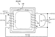
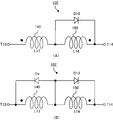
- FIG. 1A shows an example of the configuration of a DC current limiting coil according to the first embodiment.
- FIG. 1B shows another example of the configuration of the DC current limiting coil according to the first embodiment. It is a figure which shows an example of the voltage applied to the DC current limiting coil of FIG. 1, and the electric current which flows there. It is a figure which shows an example of a structure of the magnetic circuit of the current-limiting coil for DC feeding of FIG. It is a figure which shows an example of the time passage of an electric current when the voltage E10 is applied to the magnetic circuit of FIG.
- FIG. 1 (A) shows another example of the voltage applied to the current-limiting coil for direct current power supply of FIG. 1 (A), and the electric current which flows there. It is a figure which shows an example of a structure of the current limiting coil of FIG. 1 (A) by which two coils were wound and wound on the left leg part of a rectangular core. It is a figure which shows an example of a structure of the current limiting coil of FIG. 1 (A) by which two coils were each wound by the left leg part and right leg part of a rectangular-shaped core. It is a figure which shows an example of a structure of the current limiting coil of FIG. 1 (A) which has the core to which the path
- FIG. 12A shows an example of a basic configuration of the DC current limiting coil according to the second embodiment.
- FIG. 12 (B) shows an example of the configuration of the DC power feeding current limiting coil according to the second embodiment to which a back electromotive force suppression diode is added. It is a figure which shows an example of the voltage applied to the current-limiting coil for DC power feeding of FIG. 12 (A), and the electric current which flows there. It is a figure which shows an example of a structure of the magnetic circuit of the current-limiting coil for DC electric power feeding of FIG. 12 (A).
- FIG. 17 It is a figure which shows an example of the time passage of the electric current when the voltage E20 is applied to the magnetic circuit of FIG. It is a figure which shows an example of a structure of the current limiting coil of FIG. 17 by which two coils were piled around the left leg part of the rectangular core. It is a figure which shows an example of a structure of the current limiting coil of FIG. 17 by which two coils were wound by the left leg part and right leg part of a rectangular core, respectively. It is a figure which shows an example of a structure of the current limiting coil of FIG. 17 which has the core to which the path
- FIG. 1 shows an example of the configuration of DC current-limiting coils 101 and 101 ′ according to the first embodiment of the present invention.
- FIG. 3 shows an example of the configuration of the magnetic circuit of the DC current limiting coils 101 and 101 ′ shown in FIG.
- the current limiting coil 101 includes a coil 110, a coil 120, a core 130, a diode D11, and a diode D12.
- the current limiting coil 101 ′ also includes a coil 110, a coil 120, a core 130, a diode D11, and a diode D12. 2 and 3, the diode D12 is not shown, but the current limiting coils 101 and 101 ′ include the diode D12.
- the coil 110 and the coil 120 are connected in series and in the direction of summing connection between the terminal T11 and the terminal T12. That is, the self-inductances of the coil 110 and the coil 120 are L11 and L12, respectively, and the mutual inductance is M1. At this time, when the diode D11 and the diode D12 are not provided, the coil 110 and the coil 120 are connected so that the combined inductance of the current limiting coils 101 and 101 ′ is L11 + L12 + 2M1.
- a diode D11 and a diode D12 are connected to both ends of the coil 120 so that currents flow in opposite directions.
- the diode D11 has an anode connected to the connection point side of the coils 110 and 120, and a cathode connected to the terminal T12 side.
- the diode D12 has a cathode connected to the connection point side of the coils 110 and 120, and an anode connected to the terminal T12 side.
- the current flowing from the terminal T11 to the terminal T12 does not flow through the coil 120 but flows through the diode D11.
- a diode D11 and a diode D12 are connected to both ends of the coil 120 and the coil 110 so that currents flow in opposite directions.
- the diode D11 has an anode connected to the connection point side of the coils 110 and 120, and a cathode connected to the terminal T12 side.
- the diode D12 has an anode connected to the connection point side of the coil 110 and the coil 120, and a cathode connected to the terminal T11 side. Immediately after a large voltage is suddenly applied, the current flowing from the terminal T11 to the terminal T12 does not flow through the coil 120 but flows through the diode D11. The current flowing in the opposite direction does not flow through the coil 110 but flows through the diode D12. For this reason, immediately after a large voltage is suddenly applied, it can be considered that one of the coil 120 and the coil 110 is short-circuited.
- the coil 110 and the coil 120 are wound around the core 130.
- the core 130 is made of a material that can easily pass magnetic flux such as iron.
- the core 130 may be made of a material other than iron as long as it is a material that allows easy passage of magnetic flux. Since the operations of the current limiting coil 101 and the current limiting coil 101 ′ are the same, the current limiting coil 101 will be described below as an example.
- the current limiting coil 101 is inserted in the middle of the DC power supply line. Normally (that is, when a short circuit accident or the like does not occur), a substantially constant current flows through the coil 110 and the coil 120, and a magnetic flux ⁇ ′ is generated inside the core 130 by this current. At this time, the coil 110 and the coil 120 can be regarded as simple wiring.
- a short circuit accident occurs, for example, as shown in FIG. 2, when a large voltage E10 is applied suddenly with the terminal T11 and the terminal T12 as the positive side and the negative side, respectively, a voltage (E10-Vd) is applied to the coil 110.
- the exciting current im1 flows through the coil 110 from the terminal T11 to the terminal T12.
- the signs of + and ⁇ attached to both ends of the coil 110 indicate the direction of voltage drop. Since the coil 120 is considered to be short-circuited as described above, the exciting current im1 hardly flows through the coil 120. Vd is a voltage drop due to the diode D11.
- a magnetic flux ⁇ m1 is generated inside the core 130 by the exciting current im1.
- An electromotive force is generated in the coil 120 by the magnetic flux ⁇ m1. 2 and 3, the signs of + and ⁇ attached to both ends of the coil 120 indicate the direction of the electromotive force.
- a current i12 that loops between the coil 120 and the diode D11 flows.
- the current i12 attempts to generate a magnetic flux ⁇ 12 in the coil 120.
- the current i11 flows through the coil 110, and a magnetic flux ⁇ 11 having a magnitude that just cancels the magnetic flux ⁇ 12 is generated.
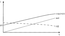
- the current i flowing between the terminal T11 and the terminal T12 is raised by the current value of the current i11 from the exciting current im1. That is, immediately after the voltage E10 is applied between the terminal T11 and the terminal T12, the current value of the current i flowing between the terminal T11 and the terminal T12 is the current value of the current i11. If it is assumed that there is no leakage magnetic flux in the coils 110 and 120, then the current value of the current i increases linearly. However, actually, there is a leakage magnetic flux in the coil 110 and the coil 120. Under the influence of this leakage magnetic flux, when time elapses, the magnetic flux ⁇ 11 and the magnetic flux ⁇ 12 decrease, and the current i11 and the current i12 decrease.
- the current limiting coil 101 has a fast rise of the current i immediately after the voltage E10 is applied, and suppresses the increase of the current i as time elapses.
- the diode D11 is required when the voltage E10 is applied with the terminal T11 and the terminal T12 as the positive side and the negative side, respectively. In this case, the diode D12 is not necessary.
- FIG. 6 shows an example of the configuration of a current limiting coil 101A in which two coils 110A and 120A are overlapped and wound around the left leg P11 of the rectangular core 130A.
- Current limiting coil 101A includes a coil 110A, a coil 120A, and a core 130A.
- the core 130A includes a yoke Y11, a yoke Y12, a leg part P11, and a leg part P12.
- the yoke Y11 and the yoke Y12 are opposed to each other.
- the leg P11 connects the left end of the yoke Y11 and the left end of the yoke Y12.
- the leg P12 connects the right end of the yoke Y11 and the right end of the yoke Y12.
- the core 130A has one or more gaps.
- the yoke Y12 has a gap AG11 in the middle.
- the yoke Y11, the leg part P11, or the leg part P12 may have a gap. If there is a gap in the core 130A, the magnetic flux leakage increases and the core 130A is less likely to be magnetically saturated.
- the windings of the coils 110A and 120A are wound around the leg P11 in opposite directions (for example, the coil 110A is counterclockwise and the coil 120A is clockwise).
- a terminal T11 and a terminal T12 are respectively provided at one end of the coil 110A and one end of the coil 120A (the beginning of winding of the coil 110A and the beginning of winding of the coil 120A) arranged on the yoke Y11 side.
- the other end of the coil 110A arranged on the yoke Y12 side and the other end of the coil 120A (the end of winding of the coil 110A and the end of winding of the coil 120A) are connected.
- the windings of the coil 110A and the coil 120A may be wound not in the leg part P11 but in the reverse direction on the leg part P12.
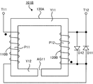
- FIG. 7 shows an example of the configuration of a current-limiting coil 101B in which two coils 110B and 120B are wound around a left leg P11 and a right leg P12 of a rectangular core 130A, respectively.
- Current limiting coil 101B includes a coil 110B, a coil 120B, and a core 130A.
- the core 130A of the current limiting coil 101B is the same as that of the current limiting coil 101A.
- the winding of the coil 110B is wound around the leg P11 counterclockwise.
- the winding of the coil 120B is wound around the leg P12 counterclockwise.
- a terminal T11 and a terminal T12 are provided at the end of the coil 110B on the yoke Y11 side and the end of the coil 120B on the yoke Y11 side (the beginning of winding of the coil 110B and the beginning of winding of the coil 120B), respectively.
- the end of coil 110B on the yoke Y12 side and the end of coil 120B on the yoke Y12 side (the end of winding of coil 110B and the end of winding of coil 120B) are connected.
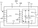
- FIG. 8 shows an example of the configuration of a current limiting coil 101C having a core 130B to which a leakage magnetic flux path is added adjacent to a rectangular portion.
- Current limiting coil 101C includes a coil 110B, a coil 120B, and a core 130B.
- the core 130B includes a yoke Y11, a yoke Y12, an extension yoke Y13, an extension yoke Y14, a leg part P11, a leg part P12, and a leg part P13.
- the yoke Y11 and the yoke Y12 are opposed to each other.
- the extension yoke Y13 is obtained by extending the yoke Y11.
- the extension yoke Y14 is obtained by extending the yoke Y12.
- the leg P11 connects the left end of the yoke Y11 and the left end of the yoke Y12.
- the leg P12 connects the right end of the yoke Y11 and the right end of the yoke Y12, that is, the connecting portion between the yoke Y11 and the extension yoke Y13 and the connecting portion between the yoke Y12 and the extension yoke Y14.
- the leg portion P13 includes the right end portion of the extension yoke Y13 and the right end portion of the extension yoke Y14 (the end portion of the extension yoke Y13 opposite to the yoke Y11 and the end portion of the extension yoke Y14 opposite to the yoke Y12). Link. However, the leg part P13 has a gap (gap) AG12 in the middle.
- the coils 110B and 120B in the current limiting coil 101C are the same as those in the current limiting coil 101B. That is, the winding of the coil 110B is wound around the leg P11 counterclockwise. The winding of the coil 120B is wound around the leg P12 counterclockwise. A terminal T11 and a terminal T12 are provided at the end of the coil 110B on the yoke Y11 side and the end of the coil 120B on the yoke Y11 side (the beginning of winding of the coil 110B and the beginning of winding of the coil 120B), respectively.
- the end of coil 110B on the yoke Y12 side and the end of coil 120B on the yoke Y12 side (the end of winding of coil 110B and the end of winding of coil 120B) are connected.
- the yoke Y11, the yoke Y12, the leg part P11, and the leg part P12 form a rectangular part.
- the expansion yoke Y13, the leg P13, and the expansion yoke Y14 serve as a leakage magnetic flux path. In the current limiting coil 101C, the leakage magnetic flux can pass not only in the air but also through the extension yoke Y13, the leg P13, and the extension yoke Y14.
- the core 130B may have one or more gaps in addition to the gap AG12.
- the yoke Y11, the yoke Y12, the extension yoke Y13, the extension yoke Y14, the leg part P11, or the leg part P12 may have a gap.
- FIG. 9 shows an example of the configuration of a current limiting coil 101D having a core 130C in which a leakage magnetic flux path is added in the middle of the rectangular portion.
- Current limiting coil 101D includes a coil 110B, a coil 120B, and a core 130C.
- the core 130C includes a yoke Y11, a yoke Y12, a leg part P11, a leg part P12, and a leg part P14.
- the yoke Y11 and the yoke Y12 are opposed to each other.
- the leg P11 connects the left end of the yoke Y11 and the left end of the yoke Y12.
- the leg P12 connects the right end of the yoke Y11 and the right end of the yoke Y12.
- the leg part P14 connects the intermediate part of the yoke Y11 and the intermediate part of the yoke Y12.
- the leg part P14 has a gap (gap) AG13 in the middle.
- Coil 110B and coil 120B in current limiting coil 101D are the same as those of current limiting coil 101B. That is, the winding of the coil 110B is wound around the leg P11 counterclockwise. The winding of the coil 120B is wound around the leg P12 counterclockwise. A terminal T11 and a terminal T12 are provided at the end of the coil 110B on the yoke Y11 side and the end of the coil 120B on the yoke Y11 side (the beginning of winding of the coil 110B and the beginning of winding of the coil 120B), respectively.
- the end of coil 110B on the yoke Y12 side and the end of coil 120B on the yoke Y12 side are connected.
- the leg part P14 becomes a path of leakage magnetic flux.
- the leakage magnetic flux can pass through the leg P14 as well as in the air.
- the core 130C may have one or more gaps in addition to the gap AG13.
- the yoke Y11, the yoke Y12, the leg part P11, or the leg part P12 may have a gap.
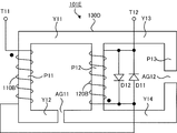
- FIG. 10 shows an example of the configuration of a current limiting coil 101E having a core 130D to which a leakage magnetic flux path is added adjacent to a rectangular portion having a gap AG11.
- Current limiting coil 101E includes a coil 110B, a coil 120B, and a core 130D.
- the core 130D is different from the core 130B of FIG. 8 in that the rectangular portion has one or more gaps (gap).
- the yoke Y12 has a gap AG11 in the middle.
- the core 130D is the same as the core 130B.
- the yoke Y11, the leg part P11, or the leg part P12 may have a gap.
- the extension yoke Y13 or the extension yoke Y14 may have a gap.
- Coil 110B and coil 120B in current limiting coil 101E are the same as those of current limiting coil 101B and current limiting coil 101C.
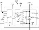
- FIG. 11 shows an example of the configuration of a current limiting coil 101F having a core 130E in which a leakage magnetic flux path is added in the middle of the rectangular portion and next to the rectangular portion.
- Current limiting coil 101F includes a coil 110B, a coil 120B, and a core 130E.
- the core 130E is obtained by adding an extension yoke Y13, an extension yoke Y14, and a leg P13 to the core 130C of FIG.
- the core 130E includes a yoke Y11, a yoke Y12, an extension yoke Y13, an extension yoke Y14, a leg part P11, a leg part P12, a leg part P13, and a leg part P14.
- the yoke Y11 and the yoke Y12 are opposed to each other.
- the extension yoke Y13 is obtained by extending the yoke Y11.
- the extension yoke Y14 is obtained by extending the yoke Y12.
- the leg P11 connects the left end of the yoke Y11 and the left end of the yoke Y12.
- the leg P12 connects the right end of the yoke Y11 and the right end of the yoke Y12, that is, the connecting portion between the yoke Y11 and the extension yoke Y13 and the connecting portion between the yoke Y12 and the extension yoke Y14.
- the leg portion P13 includes the right end portion of the extension yoke Y13 and the right end portion of the extension yoke Y14 (the end portion of the extension yoke Y13 opposite to the yoke Y11 and the end portion of the extension yoke Y14 opposite to the yoke Y12). Link. However, the leg part P13 has a gap AG12 in the middle.
- the leg part P14 connects the intermediate part of the yoke Y11 and the intermediate part of the yoke Y12. However, the leg part P14 has a gap AG13 in the middle.
- the yoke Y11, the yoke Y12, the extension yoke Y13, the extension yoke Y14, the leg part P11, or the leg part P12 may have a gap.
- Coil 110B and coil 120B in current limiting coil 101F are the same as those of current limiting coil 101B and current limiting coil 101D.
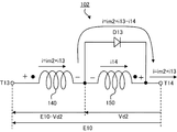
- FIG. 12A shows an example of a basic configuration of the DC current limiting coil 102 according to the second embodiment.
- FIG. 14 shows an example of the configuration of the magnetic circuit of the DC current limiting coil 102 of FIG.
- the current limiting coil 102 includes a coil 140, a coil 150, a core 160, and a diode D13.
- the coil 140 and the coil 150 are connected in the direction of differential connection in series between the terminal T13 and the terminal T14. That is, the self-inductances of the coil 140 and the coil 150 are L13 and L14, respectively, and the mutual inductance is M1 ′.
- the coil 140 and the coil 150 are connected so that the combined inductance of the current limiting coils 102 and 102 ′ becomes L13 + L14-2M1 ′.
- a diode D13 is connected to both ends of the coil 150 so that current flows from the terminal T13 toward the terminal T14. That is, in the example of FIG. 12A, the diode D13 has an anode connected to the connection point side of the coil 140 and the coil 150, and a cathode connected to the terminal T14 side. Immediately after a large voltage is suddenly applied, the current flowing from the terminal T13 toward the terminal T14 does not flow through the coil 150 but flows through the diode D13. For this reason, immediately after a large voltage is suddenly applied, the coil 150 can be regarded as being short-circuited.
- the coil 140 and the coil 150 are wound around the core 160.
- the core 160 is made of a material that can easily pass magnetic flux such as iron.
- the core 160 may be made of a material other than iron as long as it is a material through which magnetic flux can easily pass.
- the current limiting coil 102 is inserted in the middle of the DC power supply line. Normally (that is, when a short circuit accident or the like has not occurred), a substantially constant current flows through the coil 140 and the coil 150, and a magnetic flux ⁇ 1 ′ and a magnetic flux ⁇ 2 ′ are generated in the core 160 by this current. .
- the magnetic flux ⁇ 1 ′ and the magnetic flux ⁇ 2 ′ are in opposite directions and cancel each other.
- the coil 140 and the coil 150 can be regarded as simple wiring. When the number of turns of the coil 140 and the coil 150 is the same, the magnetic flux inside the core 160 is substantially zero.
- a short circuit accident occurs, for example, as shown in FIG.
- a magnetic flux ⁇ m2 is generated inside the core 160 by the exciting current im2.
- An electromotive force is generated in the coil 150 by the magnetic flux ⁇ m2.
- the symbols “+” and “ ⁇ ” attached to both ends of the coil 150 indicate the direction of the electromotive force.
- This electromotive force causes a current i14 to flow through the coil 150.
- the current i14 attempts to generate a magnetic flux ⁇ 14 in the coil 150.
- the current i13 flows through the coil 140, and a magnetic flux ⁇ 13 having a magnitude that just cancels the magnetic flux ⁇ 14 is generated.
- the magnetic flux inside the core 160 does not change from ⁇ m2.
- the current i flowing between the terminal T13 and the terminal T14 is raised by the current value of the current i13 from the exciting current im2.
- the current value of the current i flowing between the terminal T13 and the terminal T14 is the current value of the current i13. If it is assumed that there is no leakage magnetic flux in the coil 140 and the coil 150, then the current value of the current i increases linearly. However, actually, there is a leakage magnetic flux in the coil 140 and the coil 150. Under the influence of this leakage magnetic flux, when time elapses, the magnetic flux ⁇ 13 and the magnetic flux ⁇ 14 decrease, and the current i13 and the current i14 decrease.
- FIG. 12A shows an example in which the diode D13 is connected to both ends of the coil 150.
- the diode D13 is not connected to both ends of the coil 150, but the current flows from the terminal T13 to the both ends of the coil 140. You may connect so that it may flow toward T14. In this case, it can be considered that the coil 140 is short-circuited immediately after a large voltage is suddenly applied.
- the current limiting coil is installed on a high-voltage DC power supply line together with a circuit breaker.
- the current is interrupted by the circuit breaker.
- a back electromotive force is generated in the current limiting coil.
- FIG. 12B shows an example of the configuration of the DC current limiting coil 102 ′ according to the second embodiment to which the back electromotive force suppression diode Da is added.
- the current limiting coil 102 ′ is obtained by adding a back electromotive force suppression diode Da to the current limiting coil 102.
- the back electromotive force suppression diode Da has an anode connected to the connection point side of the coils 140 and 150 and a cathode connected to the terminal T13 side.
- the signs of + and ⁇ attached to both ends of the coil 140 and the coil 150 indicate the direction of the back electromotive force.
- the current ia flowing due to the counter electromotive force of the coil 140 flows through a loop formed by the counter electromotive force suppressing diode Da and the coil 140.
- the current ib that flows due to the counter electromotive force of the coil 150 flows through a loop formed by the diode D13 and the coil 150.
- the functions of the back electromotive force suppression diode Da and the diode D13 are opposite to those in the example of FIG.
- a magnetic flux ⁇ ′ is usually generated in the core 130.
- PHI magnetic flux
- m1 magnetic flux in the core 130 changes from ⁇ ′ to ⁇ ′ + ⁇ m1.
- Magnetic saturation is undesirable because magnetic saturation increases the current through the coil abruptly.
- the directions of the magnetic flux ⁇ ′ and the magnetic flux ⁇ m1 are the same, the current limiting coils 101 and 101 ′ are relatively easily magnetically saturated.
- the magnetic flux ⁇ 1 ′ is normally generated from the coil 140 and the magnetic flux ⁇ 2 ′ is generated from the coil 150.
- the magnetic flux ⁇ 1 ′ and the magnetic flux ⁇ 2 ′ are opposite to each other and cancel each other. For this reason, when the number of turns of the coil 140 and the coil 150 is the same, the magnetic flux in the core 160 is substantially zero.
- the magnetic flux in the core 160 changes from approximately 0 to ⁇ m2.
- the current limiting coils 102 and 102 ′ are less likely to be magnetically saturated because the width in which the magnetic flux can be changed is larger than that of the current limiting coils 101 and 101 ′.
- a core without a gap can be used as the core 160.
- a rectangular core 130A having a gap AG1 is used as the core 160, and the coil 140 is connected to the leg P1 or the leg P2 of the core 130A.
- the coil 150 can be wound in layers.
- a rectangular core 130A having a gap AG1 is used as the core 160, and the coil 140 is wound around the leg P1 of the core 130A.
- the coil 150 can be wound around the part P2. Further, in the current limiting coils 102 and 102 ′, the cores 130B to 130E shown in FIGS. 8 to 11 are used as the core 160, the coil 140 is wound around the leg part P1, and the coil 150 is wound around the leg part P2. Can turn.
- the configurations of the cores 130A to 130E shown in FIGS. 6 to 11 are examples and are not limited.
- cores having various configurations can be used as the core 130 and the core 160.
- various shapes such as an EI core, an EE core, and a UU core can be used.
- FIG. 17 shows an example of the configuration of a DC current limiting coil 201 according to the third embodiment of the present invention.
- FIG. 19 shows an example of the configuration of the magnetic circuit of the DC current limiting coil 201 of FIG.
- the current limiting coil 201 includes a coil 210, a coil 220, and a core 230.
- the coil 210 and the coil 220 are differentially connected in series between the terminal T21 and the terminal T22. That is, the self-inductances of the coils 210 and 220 are L21 and L22, respectively, and the mutual inductance is M2.
- the combined inductance of the current limiting coil 201 is L21 + L22-2M2.
- the coil 210 and the coil 220 are wound around the core 230.
- the core 230 is made of a material that can easily pass magnetic flux such as iron.
- the core 230 may be made of a material other than iron as long as it is a material that allows easy passage of magnetic flux.
- the current limiting coil 201 is inserted in the middle of the DC power supply line. Normally (that is, when no short circuit accident or the like has occurred), a substantially constant current flows through the coils 210 and 220. This current generates magnetic fluxes by the coils 210 and 220 in the core 230, respectively, but these magnetic fluxes are in opposite directions and cancel each other. At this time, the coil 210 and the coil 220 can be regarded as simple wiring.
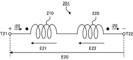
- a short circuit accident occurs, for example, as shown in FIG. 18, when voltage E20 is applied with terminals T21 and T22 set to the positive side and the negative side, respectively, the coil 210 and the coil 220 are directed from the terminal T21 toward the terminal T22. A current i20 flows.
- the current i ⁇ b> 20 generates a magnetic flux ⁇ M21 due to the coil 210 and a magnetic flux ⁇ M22 due to the coil 220, inside the core 230.
- a voltage E21 and a voltage E22 are generated in the coil 210 and the coil 220, respectively, by the magnetic flux ⁇ M21 and the magnetic flux ⁇ M22 .
- E20 E21 + E22. Since the coils 210 and 220 are differentially connected, the magnetic flux ⁇ M21 and the magnetic flux ⁇ M22 cancel each other.
- the mutual inductance 2M2 is subtracted from the self-inductances L21 and L22 of the coils 210 and 220, and the combined inductance of the current limiting coil 201 is reduced.
- the current i20 increases with a slope of E20 / (L21 + L22-2M2).
- the rise of the current i20 is fast.
- the current i20 flows, the leakage flux [Phi L22 from leakage flux [Phi L21 and the coil 220 from the coil 210 occurs.
- Leakage magnetic flux ⁇ L21 and leakage magnetic flux ⁇ L22 pass, for example, in the air.
- a leakage inductance corresponding to each of the leakage magnetic flux ⁇ L21 and the leakage magnetic flux ⁇ L22 is generated.
- the current i20 increases, and the leakage flux ⁇ L21 and the leakage flux ⁇ L22 increase.
- the state of the magnetic flux in the magnetic circuit changes, and as shown in FIG. 20, the increase rate of the current i20 decreases and the increase of the current i20 is suppressed.
- FIG. 21 shows an example of the configuration of a current-limiting coil 201A in which two coils 210A and 220A are overlapped and wound around the left leg P21 of the rectangular core 230A.
- Current limiting coil 201A includes a coil 210A, a coil 220A, and a core 230A.
- the core 230A includes a yoke Y21, a yoke Y22, a leg part P21, and a leg part P22.
- the yoke Y21 and the yoke Y22 face each other.
- the leg P21 connects the left end of the yoke Y21 and the left end of the yoke Y22.
- the leg P22 connects the right end of the yoke Y21 and the right end of the yoke Y22.
- the windings of the coils 210A and 220A are wound around the leg portion P21 in the same direction (for example, counterclockwise).
- a terminal T21 and a terminal T22 are respectively provided at one end of the coil 210A and one end of the coil 220A (the beginning of winding of the coil 210A and the beginning of winding of the coil 220A) disposed on the yoke Y21 side.
- the other end of coil 210A and the other end of coil 220A (the end of winding of coil 210A and the end of winding of coil 220A) are connected.
- the coupling coefficient between the coil 210 and the coil 220 is close to 1, and the leakage flux ⁇ L21 and the leakage flux ⁇ L22 are small.
- the windings of the coils 210A and 220A may be wound in the same direction not on the leg part P21 but on the leg part P22.
- FIG. 22 shows an example of the configuration of a current-limiting coil 201B in which two coils 210B and 220B are wound around a left leg P21 and a right leg P22 of a rectangular core 230A.
- Current limiting coil 201B includes a coil 210B, a coil 220B, and a core 230A.
- the core 230A of the current limiting coil 201B is the same as that of the current limiting coil 201A.
- the winding of the coil 210B is wound around the leg P21 counterclockwise.
- the winding of the coil 220B is wound clockwise around the leg P22.
- a terminal T21 and a terminal T22 are provided at the end of the coil 210B on the yoke Y21 side and the end of the coil 220B on the yoke Y21 side (the beginning of winding of the coil 210B and the beginning of winding of the coil 220B), respectively.
- the end of coil 210B on the yoke Y22 side and the end of coil 220B on the yoke Y22 side (the end of winding of coil 210B and the end of winding of coil 220B) are connected.
- the current limiting coil 201B has a coupling coefficient between the coils 210B and 220B smaller than that of the current limiting coil 201A, and has more leakage flux ⁇ L21 and leakage flux ⁇ L22 than the current limiting coil 201A.
- FIG. 23 shows an example of the configuration of a current-limiting coil 201C having a core 230B to which a leakage magnetic flux path is added adjacent to a rectangular portion.
- Current limiting coil 201C includes a coil 210B, a coil 220B, and a core 230B.
- the core 230B includes a yoke Y21, a yoke Y22, an extension yoke Y23, an extension yoke Y24, a leg part P21, a leg part P22, and a leg part P23.
- the yoke Y21 and the yoke Y22 face each other.
- the extension yoke Y23 is obtained by extending the yoke Y21.
- the extension yoke Y24 is obtained by extending the yoke Y22.
- the leg P21 connects the left end of the yoke Y21 and the left end of the yoke Y22.
- the leg P22 connects the right end of the yoke Y21 and the right end of the yoke Y22, that is, the connecting portion between the yoke Y21 and the extension yoke Y23 and the connecting portion between the yoke Y22 and the extension yoke Y24.
- the leg portion P23 includes the right end portion of the extension yoke Y23 and the right end portion of the extension yoke Y24 (the end portion of the extension yoke Y23 opposite to the yoke Y21 and the end portion of the extension yoke Y24 opposite to the yoke Y22). Link. However, the leg part P23 has a gap (gap) AG21 in the middle.
- Coil 210B and coil 220B in current limiting coil 201C are the same as those of current limiting coil 201B. That is, the winding of the coil 210B is wound around the leg P21 counterclockwise. The winding of the coil 220B is wound clockwise around the leg P22.
- a terminal T21 and a terminal T22 are provided at the end of the coil 210B on the yoke Y21 side and the end of the coil 220B on the yoke Y21 side (the beginning of winding of the coil 210B and the beginning of winding of the coil 220B), respectively.
- the end of coil 210B on the yoke Y22 side and the end of coil 220B on the yoke Y22 side (the end of winding of coil 210B and the end of winding of coil 220B) are connected.
- the yoke Y21, the yoke Y22, the leg part P21, and the leg part P22 form a rectangular part.
- the extension yoke Y23, the leg part P23, and the extension yoke Y24 serve as a path for the leakage flux ⁇ L21 and the leakage flux ⁇ L22 .
- the leakage flux ⁇ L21 and the leakage flux ⁇ L22 are larger than those in the current-limiting coil 201B, and the coupling coefficient between the coils 210B and 220B is even smaller than that in the current-limiting coil 201B.
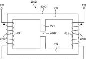
- FIG. 24 shows an example of the configuration of a current-limiting coil 201D having a core 230C in which a leakage magnetic flux path is added in the middle of the rectangular portion.
- Current limiting coil 201D includes coil 210B, coil 220B, and core 230C.
- the core 230C includes a yoke Y21, a yoke Y22, a leg part P21, a leg part P22, and a leg part P24.
- the yoke Y21 and the yoke Y22 face each other.
- the leg P21 connects the left end of the yoke Y21 and the left end of the yoke Y22.
- the leg P22 connects the right end of the yoke Y21 and the right end of the yoke Y22.
- the leg part P24 connects the intermediate part of the yoke Y21 and the intermediate part of the yoke Y22.
- the leg part P24 has a gap (gap) AG22 in the middle.
- Coil 210B and coil 220B in current limiting coil 201D are the same as those of current limiting coil 201B. That is, the winding of the coil 210B is wound around the leg P21 counterclockwise. The winding of the coil 220B is wound clockwise around the leg P22.
- a terminal T21 and a terminal T22 are provided at the end of the coil 210B on the yoke Y21 side and the end of the coil 220B on the yoke Y21 side (the beginning of winding of the coil 210B and the beginning of winding of the coil 220B), respectively.
- the end of coil 210B on the yoke Y22 side and the end of coil 220B on the yoke Y22 side (the end of winding of coil 210B and the end of winding of coil 220B) are connected.
- the leg part P24 becomes a path of the leakage magnetic flux ⁇ L21 and the leakage magnetic flux ⁇ L22 .
- the leakage magnetic flux ⁇ L21 and the leakage magnetic flux ⁇ L22 can pass through the leg portion P24 as well as in the air. For this reason, in the current limiting coil 201D, the leakage flux ⁇ L21 and the leakage flux ⁇ L22 are more than the current limiting coil 201B, and the coupling coefficient of the coil 210B and the coil 220B is further smaller than that of the current limiting coil 201B.
- the configurations of the cores 230A to 230C shown in FIGS. 21 to 24 are examples and are not limited.
- cores having various configurations can be used as the core 230.
- various shapes such as an EI core, an EE core, and a UU core can be used.
- the rise of current immediately after a large voltage is applied can be accelerated. For this reason, the operating time of a circuit breaker, a fuse, etc. can be shortened by inserting the current-limiting coil for DC power supply of the present invention in the middle of the DC power supply line. Further, according to the present invention, it is possible to suppress an increase in current as time elapses after a large voltage is applied. For this reason, by inserting the current-limiting coil for DC power supply of the present invention in the middle of the DC power supply line, the core is less likely to be magnetically saturated even if time elapses, and an excessive current is prevented from occurring suddenly. be able to.
Landscapes
- Engineering & Computer Science (AREA)
- Power Engineering (AREA)
- Emergency Protection Circuit Devices (AREA)
Abstract
限流コイル101は、和動接続の向きに接続されたコイル110とコイル120を有する。ただし、コイル120の両端には、ダイオードD11のアノードがコイル110とコイル120の接続点側に接続されており、そのカソードが端子T12側に接続されている。コイル110とコイル120は、コア130に巻回されている。端子T11と端子T12をそれぞれ正側と負側として電圧E10が印加されると、励磁電流im1が流れて、コア130の内部に磁束Φm1が生じる。磁束Φm1により、コイル120とダイオードD11をループする電流i12が流れる。電流i12は、コイル120に磁束Φ12を発生させようとする。しかし、電流i12に対応して、電流i11がコイル110に流れ、磁束Φ12をちょうど打ち消す大きさの磁束Φ11を発生させる。従って、端子T11から端子T12に向けて電流i=im1+i11が流れる。
Description
本発明は、直流給電において使用される直流給電用限流コイルに関する。
データセンタ等でサーバに高電圧直流を給電するシステムが知られている。また、スマートグリッドへの適用を目指して、380V程度の高電圧直流(HVDC:High Voltage Direct Current)送電の研究開発が進められている。
このような高電圧直流の給電線に短絡事故等が発生すると、過大電流が流れるおそれがある。この過大電流は、給電線の途中にコイルを挿入することにより、抑制することができる。電圧が急激に変化するとき、コイルのインダクタンスが電流の急激な変化を抑制する。
例えば、遮断器は、過大電流が流れ始めて時間が経過し、電流値が所定の値に達したときに電流を遮断する。
しかし、短絡事故等が発生して大きな電圧が印加されたとき、短絡事故等の発生直後の電流値は小さく、コイルに流れる電流(磁束密度)は時間とともに徐々に上昇する。このため、電流値が遮断器を動作させる値に達し、遮断器が動作して電流が遮断されるまで時間がかかる。
しかし、短絡事故等が発生して大きな電圧が印加されたとき、短絡事故等の発生直後の電流値は小さく、コイルに流れる電流(磁束密度)は時間とともに徐々に上昇する。このため、電流値が遮断器を動作させる値に達し、遮断器が動作して電流が遮断されるまで時間がかかる。
また、コイルの巻線の抵抗は非常に小さい。短絡箇所の抵抗も小さい場合、電流が遮断される前にコイルが磁気飽和すると、インダクタンスが非常に小さくなり、膨大な電流が瞬時に流れるおそれがある。
本発明の目的は、大きな電圧が印加された直後における電流の立ち上がりを早くし、その後に時間の経過とともに電流の増加を抑制することができる直流給電用限流コイルを提供することである。
上記目的を達成するために、本発明の直流給電用限流コイルは、
直流給電において使用される直流給電用限流コイルであって、
磁束を通しやすい材料で作られたコアと、
前記コアに巻回され、直列に接続された2つのコイルと、
前記2つのコイルのうちの一方のコイルの両端に接続された第1のダイオードと、
を備えることを特徴とする。
直流給電において使用される直流給電用限流コイルであって、
磁束を通しやすい材料で作られたコアと、
前記コアに巻回され、直列に接続された2つのコイルと、
前記2つのコイルのうちの一方のコイルの両端に接続された第1のダイオードと、
を備えることを特徴とする。
好ましくは、本発明の直流給電用限流コイルは、
前記2つのコイルが、和動接続の向きに接続されていることを特徴とする。
前記2つのコイルが、和動接続の向きに接続されていることを特徴とする。
好ましくは、本発明の直流給電用限流コイルは、
前記2つのコイルのうちの一方のコイルまたは他方のコイルの両端に、前記第1のダイオードと逆方向に電流が流れるように接続された第2のダイオードを備えることを特徴とする。
前記2つのコイルのうちの一方のコイルまたは他方のコイルの両端に、前記第1のダイオードと逆方向に電流が流れるように接続された第2のダイオードを備えることを特徴とする。
好ましくは、本発明の直流給電用限流コイルは、
前記2つのコイルが、差動接続の向きに接続されていることを特徴とする。
前記2つのコイルが、差動接続の向きに接続されていることを特徴とする。
好ましくは、本発明の直流給電用限流コイルは、
前記2つのコイルのうちの他方のコイルの両端に、前記第1のダイオードと逆方向に電流が流れるように接続された第2のダイオードを備えることを特徴とする。
前記2つのコイルのうちの他方のコイルの両端に、前記第1のダイオードと逆方向に電流が流れるように接続された第2のダイオードを備えることを特徴とする。
好ましくは、本発明の直流給電用限流コイルは、
前記コアが、対向する第1のヨークおよび第2のヨークと、当該第1のヨークの一方の端部および当該第2のヨークの一方の端部を連結する第1の脚部と、当該第1のヨークの他方の端部および当該第2のヨークの他方の端部を連結する第2の脚部とを有し、
前記第1のヨーク、前記第2のヨーク、前記第1の脚部、または前記第2の脚部が少なくとも1のギャップを有し、
前記2つのコイルが、前記第1の脚部または前記第2の脚部に重ね巻きされている、
ことを特徴とする。
前記コアが、対向する第1のヨークおよび第2のヨークと、当該第1のヨークの一方の端部および当該第2のヨークの一方の端部を連結する第1の脚部と、当該第1のヨークの他方の端部および当該第2のヨークの他方の端部を連結する第2の脚部とを有し、
前記第1のヨーク、前記第2のヨーク、前記第1の脚部、または前記第2の脚部が少なくとも1のギャップを有し、
前記2つのコイルが、前記第1の脚部または前記第2の脚部に重ね巻きされている、
ことを特徴とする。
好ましくは、本発明の直流給電用限流コイルは、
前記コアが、対向する第1のヨークおよび第2のヨークと、当該第1のヨークの一方の端部および当該第2のヨークの一方の端部を連結する第1の脚部と、当該第1のヨークの他方の端部および当該第2のヨークの他方の端部を連結する第2の脚部とを有し、
前記第1のヨーク、前記第2のヨーク、前記第1の脚部、または前記第2の脚部が少なくとも1のギャップを有し、
前記2つのコイルの一方が、前記第1の脚部に巻回されており、
前記2つのコイルの他方が、前記第2の脚部に巻回されている、
ことを特徴とする。
前記コアが、対向する第1のヨークおよび第2のヨークと、当該第1のヨークの一方の端部および当該第2のヨークの一方の端部を連結する第1の脚部と、当該第1のヨークの他方の端部および当該第2のヨークの他方の端部を連結する第2の脚部とを有し、
前記第1のヨーク、前記第2のヨーク、前記第1の脚部、または前記第2の脚部が少なくとも1のギャップを有し、
前記2つのコイルの一方が、前記第1の脚部に巻回されており、
前記2つのコイルの他方が、前記第2の脚部に巻回されている、
ことを特徴とする。
好ましくは、本発明の直流給電用限流コイルは、
前記コアが、対向する第1のヨークおよび第2のヨークと、当該第1のヨークの一方の端部および当該第2のヨークの一方の端部を連結する第1の脚部と、当該第1のヨークの他方の端部および当該第2のヨークの他方の端部を連結する第2の脚部と、当該第1のヨークの他方の端部から延長された第1の拡張ヨークと、当該第2のヨークの他方の端部から延長された第2の拡張ヨークと、当該第1の拡張ヨークにおける前記第1のヨークと反対側の端部と当該第2の拡張ヨークにおける前記第2のヨークと反対側の端部とを連結し、中間にギャップを有する第3の脚部とを有し、
前記2つのコイルの一方が、前記第1の脚部に巻回されており、
前記2つのコイルの他方が、前記第2の脚部に巻回されている、
ことを特徴とする。
前記コアが、対向する第1のヨークおよび第2のヨークと、当該第1のヨークの一方の端部および当該第2のヨークの一方の端部を連結する第1の脚部と、当該第1のヨークの他方の端部および当該第2のヨークの他方の端部を連結する第2の脚部と、当該第1のヨークの他方の端部から延長された第1の拡張ヨークと、当該第2のヨークの他方の端部から延長された第2の拡張ヨークと、当該第1の拡張ヨークにおける前記第1のヨークと反対側の端部と当該第2の拡張ヨークにおける前記第2のヨークと反対側の端部とを連結し、中間にギャップを有する第3の脚部とを有し、
前記2つのコイルの一方が、前記第1の脚部に巻回されており、
前記2つのコイルの他方が、前記第2の脚部に巻回されている、
ことを特徴とする。
好ましくは、本発明の直流給電用限流コイルは、
前記第1のヨーク、前記第2のヨーク、前記第1の脚部、または前記第2の脚部が少なくとも1のギャップを有することを特徴とする。
前記第1のヨーク、前記第2のヨーク、前記第1の脚部、または前記第2の脚部が少なくとも1のギャップを有することを特徴とする。
好ましくは、本発明の直流給電用限流コイルは、
前記コアが、対向する第1のヨークおよび第2のヨークと、当該第1のヨークの一方の端部および当該第2のヨークの一方の端部を連結する第1の脚部と、当該第1のヨークの他方の端部および当該第2のヨークの他方の端部を連結する第2の脚部と、当該第1のヨークの中間部分と当該第2のヨークの中間部分を連結し、中間にギャップを有する第3の脚部とを有し、
前記2つのコイルの一方が、前記第1の脚部に巻回されており、
前記2つのコイルの他方が、前記第2の脚部に巻回されている、
ことを特徴とする。
前記コアが、対向する第1のヨークおよび第2のヨークと、当該第1のヨークの一方の端部および当該第2のヨークの一方の端部を連結する第1の脚部と、当該第1のヨークの他方の端部および当該第2のヨークの他方の端部を連結する第2の脚部と、当該第1のヨークの中間部分と当該第2のヨークの中間部分を連結し、中間にギャップを有する第3の脚部とを有し、
前記2つのコイルの一方が、前記第1の脚部に巻回されており、
前記2つのコイルの他方が、前記第2の脚部に巻回されている、
ことを特徴とする。
好ましくは、本発明の直流給電用限流コイルは、
前記コアが、対向する第1のヨークおよび第2のヨークと、当該第1のヨークの一方の端部および当該第2のヨークの一方の端部を連結する第1の脚部と、当該第1のヨークの他方の端部および当該第2のヨークの他方の端部を連結する第2の脚部と、当該第1のヨークの他方の端部から延長された第1の拡張ヨークと、当該第2のヨークの他方の端部から延長された第2の拡張ヨークと、当該第1の拡張ヨークにおける前記第1のヨークと反対側の端部と当該第2の拡張ヨークにおける前記第2のヨークと反対側の端部とを連結し、中間にギャップを有する第3の脚部と、当該第1のヨークの中間部分と当該第2のヨークの中間部分を連結し、中間にギャップを有する第4の脚部とを有し、
前記2つのコイルの一方が、前記第1の脚部に巻回されており、
前記2つのコイルの他方が、前記第2の脚部に巻回されている、
ことを特徴とする。
前記コアが、対向する第1のヨークおよび第2のヨークと、当該第1のヨークの一方の端部および当該第2のヨークの一方の端部を連結する第1の脚部と、当該第1のヨークの他方の端部および当該第2のヨークの他方の端部を連結する第2の脚部と、当該第1のヨークの他方の端部から延長された第1の拡張ヨークと、当該第2のヨークの他方の端部から延長された第2の拡張ヨークと、当該第1の拡張ヨークにおける前記第1のヨークと反対側の端部と当該第2の拡張ヨークにおける前記第2のヨークと反対側の端部とを連結し、中間にギャップを有する第3の脚部と、当該第1のヨークの中間部分と当該第2のヨークの中間部分を連結し、中間にギャップを有する第4の脚部とを有し、
前記2つのコイルの一方が、前記第1の脚部に巻回されており、
前記2つのコイルの他方が、前記第2の脚部に巻回されている、
ことを特徴とする。
また、本発明の直流給電用限流コイルは、
直流給電において使用される直流給電用限流コイルであって、
磁束を通しやすい材料で作られたコアと、
前記コアに巻回され、差動接続された2つのコイルと、
を備えることを特徴とする。
直流給電において使用される直流給電用限流コイルであって、
磁束を通しやすい材料で作られたコアと、
前記コアに巻回され、差動接続された2つのコイルと、
を備えることを特徴とする。
好ましくは、本発明の直流給電用限流コイルは、
前記コアが、対向する第1のヨークおよび第2のヨークと、当該第1のヨークの一方の端部および当該第2のヨークの一方の端部を連結する第1の脚部と、当該第1のヨークの他方の端部および当該第2のヨークの他方の端部を連結する第2の脚部とを有し、
前記2つのコイルが、前記第1の脚部または前記第2の脚部に重ね巻きされている、
ことを特徴とする。
前記コアが、対向する第1のヨークおよび第2のヨークと、当該第1のヨークの一方の端部および当該第2のヨークの一方の端部を連結する第1の脚部と、当該第1のヨークの他方の端部および当該第2のヨークの他方の端部を連結する第2の脚部とを有し、
前記2つのコイルが、前記第1の脚部または前記第2の脚部に重ね巻きされている、
ことを特徴とする。
好ましくは、本発明の直流給電用限流コイルは、
前記コアが、対向する第1のヨークおよび第2のヨークと、当該第1のヨークの一方の端部および当該第2のヨークの一方の端部を連結する第1の脚部と、当該第1のヨークの他方の端部および当該第2のヨークの他方の端部を連結する第2の脚部とを有し、
前記2つのコイルの一方が、前記第1の脚部に巻回されており、
前記2つのコイルの他方が、前記第2の脚部に巻回されている、
ことを特徴とする。
前記コアが、対向する第1のヨークおよび第2のヨークと、当該第1のヨークの一方の端部および当該第2のヨークの一方の端部を連結する第1の脚部と、当該第1のヨークの他方の端部および当該第2のヨークの他方の端部を連結する第2の脚部とを有し、
前記2つのコイルの一方が、前記第1の脚部に巻回されており、
前記2つのコイルの他方が、前記第2の脚部に巻回されている、
ことを特徴とする。
好ましくは、本発明の直流給電用限流コイルは、
前記コアが、対向する第1のヨークおよび第2のヨークと、当該第1のヨークの一方の端部および当該第2のヨークの一方の端部を連結する第1の脚部と、当該第1のヨークの他方の端部および当該第2のヨークの他方の端部を連結する第2の脚部と、当該第1のヨークの他方の端部から延長された第1の拡張ヨークと、当該第2のヨークの他方の端部から延長された第2の拡張ヨークと、当該第1の拡張ヨークにおける前記第1のヨークと反対側の端部と当該第2の拡張ヨークにおける前記第2のヨークと反対側の端部とを連結し、中間にギャップを有する第3の脚部とを有し、
前記2つのコイルの一方が、前記第1の脚部に巻回されており、
前記2つのコイルの他方が、前記第2の脚部に巻回されている、
ことを特徴とする。
前記コアが、対向する第1のヨークおよび第2のヨークと、当該第1のヨークの一方の端部および当該第2のヨークの一方の端部を連結する第1の脚部と、当該第1のヨークの他方の端部および当該第2のヨークの他方の端部を連結する第2の脚部と、当該第1のヨークの他方の端部から延長された第1の拡張ヨークと、当該第2のヨークの他方の端部から延長された第2の拡張ヨークと、当該第1の拡張ヨークにおける前記第1のヨークと反対側の端部と当該第2の拡張ヨークにおける前記第2のヨークと反対側の端部とを連結し、中間にギャップを有する第3の脚部とを有し、
前記2つのコイルの一方が、前記第1の脚部に巻回されており、
前記2つのコイルの他方が、前記第2の脚部に巻回されている、
ことを特徴とする。
好ましくは、本発明の直流給電用限流コイルは、
前記コアが、対向する第1のヨークおよび第2のヨークと、当該第1のヨークの一方の端部および当該第2のヨークの一方の端部を連結する第1の脚部と、当該第1のヨークの他方の端部および当該第2のヨークの他方の端部を連結する第2の脚部と、当該第1のヨークの中間部分と当該第2のヨークの中間部分を連結し、中間にギャップを有する第3の脚部とを有し、
前記2つのコイルの一方が、前記第1の脚部に巻回されており、
前記2つのコイルの他方が、前記第2の脚部に巻回されている、
ことを特徴とする。
前記コアが、対向する第1のヨークおよび第2のヨークと、当該第1のヨークの一方の端部および当該第2のヨークの一方の端部を連結する第1の脚部と、当該第1のヨークの他方の端部および当該第2のヨークの他方の端部を連結する第2の脚部と、当該第1のヨークの中間部分と当該第2のヨークの中間部分を連結し、中間にギャップを有する第3の脚部とを有し、
前記2つのコイルの一方が、前記第1の脚部に巻回されており、
前記2つのコイルの他方が、前記第2の脚部に巻回されている、
ことを特徴とする。
本発明によれば、大きな電圧が印加された直後における電流の立ち上がりを早くし、その後に時間の経過とともに電流の増加を抑制することができる。
以下、本発明の実施形態に係る直流給電用限流コイルについて図面を参照しながら詳細に説明する。なお、実施形態を説明する全図において、共通の構成要素には同一の符号を付し、繰り返しの説明を省略する。
図1は、本発明の第1の実施形態に係る直流給電用限流コイル101,101’の構成の例を示す。図3は、図1の直流給電用限流コイル101,101’の磁気回路の構成の一例を示す。
限流コイル101は、コイル110と、コイル120と、コア130と、ダイオードD11と、ダイオードD12とを有する。限流コイル101’も、限流コイル101と同様に、コイル110と、コイル120と、コア130と、ダイオードD11と、ダイオードD12とを有する。なお、図2と図3には、ダイオードD12を図示していないが、限流コイル101,101’はダイオードD12を含む。
コイル110とコイル120は、端子T11と端子T12の間に直列に和動接続の向きに接続されている。すなわち、コイル110とコイル120の自己インダクタンスをそれぞれL11とL12、相互インダクタンスをM1とする。このとき、ダイオードD11とダイオードD12が無い場合には、限流コイル101,101’の合成インダクタンスがL11+L12+2M1となるようにコイル110とコイル120は接続されている。
限流コイル101は、コイル110と、コイル120と、コア130と、ダイオードD11と、ダイオードD12とを有する。限流コイル101’も、限流コイル101と同様に、コイル110と、コイル120と、コア130と、ダイオードD11と、ダイオードD12とを有する。なお、図2と図3には、ダイオードD12を図示していないが、限流コイル101,101’はダイオードD12を含む。
コイル110とコイル120は、端子T11と端子T12の間に直列に和動接続の向きに接続されている。すなわち、コイル110とコイル120の自己インダクタンスをそれぞれL11とL12、相互インダクタンスをM1とする。このとき、ダイオードD11とダイオードD12が無い場合には、限流コイル101,101’の合成インダクタンスがL11+L12+2M1となるようにコイル110とコイル120は接続されている。
ただし、図1(A)に示すように、限流コイル101では、コイル120の両端に、互いに逆方向に電流が流れるようにダイオードD11とダイオードD12が接続されている。例えば、ダイオードD11はアノードがコイル110とコイル120の接続点側に接続され、カソードが端子T12側に接続されている。ダイオードD12はカソードがコイル110とコイル120の接続点側に接続され、アノードが端子T12側に接続されている。急に大きな電圧が印加された直後に端子T11から端子T12に向かって流れる電流は、コイル120を流れず、ダイオードD11を通って流れる。また、その逆方向に流れる電流は、コイル120を流れず、ダイオードD12を通って流れる。このため、急に大きな電圧が印加された直後には、コイル120は短絡されているとみなすことができる。
一方、図1(B)に示すように、限流コイル101’では、コイル120とコイル110の両端に、互いに逆方向に電流が流れるようにダイオードD11とダイオードD12が接続されている。例えば、ダイオードD11はアノードがコイル110とコイル120の接続点側に接続され、カソードが端子T12側に接続されている。ダイオードD12はアノードがコイル110とコイル120の接続点側に接続され、カソードが端子T11側に接続されている。急に大きな電圧が印加された直後に端子T11から端子T12に向かって流れる電流は、コイル120を流れず、ダイオードD11を通って流れる。また、その逆方向に流れる電流は、コイル110を流れず、ダイオードD12を通って流れる。このため、急に大きな電圧が印加された直後には、コイル120とコイル110のいずれか一方が短絡されているとみなすことができる。
一方、図1(B)に示すように、限流コイル101’では、コイル120とコイル110の両端に、互いに逆方向に電流が流れるようにダイオードD11とダイオードD12が接続されている。例えば、ダイオードD11はアノードがコイル110とコイル120の接続点側に接続され、カソードが端子T12側に接続されている。ダイオードD12はアノードがコイル110とコイル120の接続点側に接続され、カソードが端子T11側に接続されている。急に大きな電圧が印加された直後に端子T11から端子T12に向かって流れる電流は、コイル120を流れず、ダイオードD11を通って流れる。また、その逆方向に流れる電流は、コイル110を流れず、ダイオードD12を通って流れる。このため、急に大きな電圧が印加された直後には、コイル120とコイル110のいずれか一方が短絡されているとみなすことができる。
コイル110とコイル120は、コア130に巻かれている。コア130は、鉄のような磁束を通しやすい材料で作られている。ただし、コア130は、磁束を通しやすい材料であれば、鉄以外の材料で作られていてもよい。
限流コイル101と限流コイル101’の動作は同様であるため、以下では限流コイル101を例に説明する。
限流コイル101と限流コイル101’の動作は同様であるため、以下では限流コイル101を例に説明する。
限流コイル101は、直流の給電線の途中に挿入される。通常(すなわち、短絡事故等が起こっていないとき)、コイル110とコイル120には略一定の電流が流れており、この電流によりコア130の内部には磁束Φ’が生じている。このとき、コイル110とコイル120は単なる配線とみなせる。短絡事故等が起こり、例えば、図2に示すように、端子T11と端子T12をそれぞれ正側と負側として急に大きな電圧E10が印加されると、コイル110に電圧(E10-Vd)がかかり、端子T11から端子T12に向けてコイル110に励磁電流im1が流れる。コイル110の両端に付した+と-の符号は電圧降下の向きを示す。なお、上述したようにコイル120は短絡されていると見なされるため、励磁電流im1はコイル120にはほとんど流れない。VdはダイオードD11による電圧降下である。
このとき、図3に示すように、励磁電流im1によって、コア130の内部に磁束Φm1が生じる。磁束Φm1によりコイル120に起電力が生じる。図2と図3においてコイル120の両端に付した+と-の符号は起電力の向きを示す。この起電力により、コイル120とダイオードD11をループする電流i12が流れる。電流i12は、コイル120に磁束Φ12を発生させようとする。しかし、電流i12に対応して、コイル110に電流i11が流れ、磁束Φ12をちょうど打ち消す大きさの磁束Φ11を発生させる。磁束Φ11と磁束Φ12が打ち消し合うため、コア130の内部の磁束はΦm1から変化しない。
従って、端子T11と端子T12をそれぞれ正側と負側として電圧E10が印加されたとき、端子T11から端子T12に向けて電流i=im1+i11が流れる。
従って、端子T11と端子T12をそれぞれ正側と負側として電圧E10が印加されたとき、端子T11から端子T12に向けて電流i=im1+i11が流れる。
図4に示すように、端子T11と端子T12間に流れる電流iは、励磁電流im1から電流i11の電流値だけ嵩上げされる。すなわち、端子T11と端子T12間に電圧E10が印加された直後に、端子T11と端子T12間に流れる電流iの電流値は、電流i11の電流値である。コイル110とコイル120に漏れ磁束がないと仮定すると、その後、電流iの電流値は直線的に増加する。しかし、実際には、コイル110とコイル120には漏れ磁束が存在する。この漏れ磁束の影響により、時間が経過すると、磁束Φ11と磁束Φ12が減少し、電流i11と電流i12が減少する。このため、時間が経過するにつれて、端子T11と端子T12間に流れる電流iの増加率が減少する。このように、限流コイル101は、電圧E10が印加された直後における電流iの立ち上がりが早く、時間が経過するにつれて電流iの増加を抑制する。
ダイオードD11は、端子T11と端子T12をそれぞれ正側と負側として電圧E10が印加される場合に必要となる。この場合、ダイオードD12は必要ない。
ダイオードD12は、図2の例とは逆に、端子T12と端子T11をそれぞれ正側と負側として電圧E10が印加される場合に必要となる。図5に示すように、電圧E10が印加されたとき、電流i=im1+i11は端子T12から端子T11に向けてダイオードD12とコイル110を通って流れる。また、電流i12はコイル120とダイオードD12をループして流れる。なお、この場合、ダイオードD11は必要ない。
ダイオードD12は、図2の例とは逆に、端子T12と端子T11をそれぞれ正側と負側として電圧E10が印加される場合に必要となる。図5に示すように、電圧E10が印加されたとき、電流i=im1+i11は端子T12から端子T11に向けてダイオードD12とコイル110を通って流れる。また、電流i12はコイル120とダイオードD12をループして流れる。なお、この場合、ダイオードD11は必要ない。
以下に、限流コイル101の具体的な構成例について説明する。
図6は、矩形状のコア130Aの左側の脚部P11に2つのコイル110Aとコイル120Aが重ね巻きされた限流コイル101Aの構成の一例を示す。
限流コイル101Aは、コイル110Aと、コイル120Aと、コア130Aとを含む。
コア130Aは、ヨークY11と、ヨークY12と、脚部P11と、脚部P12とを有する。ヨークY11とヨークY12は対向している。脚部P11は、ヨークY11の左の端部とヨークY12の左の端部を連結する。脚部P12は、ヨークY11の右の端部とヨークY12の右の端部を連結する。
コア130Aは1つ以上のギャップ(隙間)を有する。例えば、図6の例では、ヨークY12が中間にギャップAG11を有する。なお、ヨークY11、脚部P11、または脚部P12がギャップを有していてもよい。コア130Aにギャップがあると、漏れ磁束が増加し、コア130Aは磁気飽和しにくくなる。
図6は、矩形状のコア130Aの左側の脚部P11に2つのコイル110Aとコイル120Aが重ね巻きされた限流コイル101Aの構成の一例を示す。
限流コイル101Aは、コイル110Aと、コイル120Aと、コア130Aとを含む。
コア130Aは、ヨークY11と、ヨークY12と、脚部P11と、脚部P12とを有する。ヨークY11とヨークY12は対向している。脚部P11は、ヨークY11の左の端部とヨークY12の左の端部を連結する。脚部P12は、ヨークY11の右の端部とヨークY12の右の端部を連結する。
コア130Aは1つ以上のギャップ(隙間)を有する。例えば、図6の例では、ヨークY12が中間にギャップAG11を有する。なお、ヨークY11、脚部P11、または脚部P12がギャップを有していてもよい。コア130Aにギャップがあると、漏れ磁束が増加し、コア130Aは磁気飽和しにくくなる。
コイル110Aとコイル120Aの巻線は、脚部P11に逆向き(例えば、コイル110Aは左回り、コイル120Aは右回り)に重ね巻きされている。ヨークY11側に配置されているコイル110Aの一方の端部とコイル120Aの一方の端部(コイル110Aの巻き初めとコイル120Aの巻き初め)にそれぞれ端子T11と端子T12が設けられる。ヨークY12側に配置されているコイル110Aの他方の端部とコイル120Aの他方の端部(コイル110Aの巻き終わりとコイル120Aの巻き終わり)は接続される。
なお、コイル110Aとコイル120Aの巻線は、脚部P11ではなく、脚部P12に逆向きに重ね巻きされていてもよい。
なお、コイル110Aとコイル120Aの巻線は、脚部P11ではなく、脚部P12に逆向きに重ね巻きされていてもよい。
図7は、矩形状のコア130Aの左側の脚部P11と右側の脚部P12に2つのコイル110Bとコイル120Bがそれぞれ巻回された限流コイル101Bの構成の一例を示す。
限流コイル101Bは、コイル110Bと、コイル120Bと、コア130Aとを含む。
限流コイル101Bのコア130Aは、限流コイル101Aのものと同一である。
コイル110Bの巻線は、脚部P11に左回りに巻回されている。コイル120Bの巻線は、脚部P12に左回りに巻回されている。コイル110BのヨークY11側の端部とコイル120BのヨークY11側の端部(コイル110Bの巻き初めとコイル120Bの巻き初め)にそれぞれ端子T11と端子T12が設けられる。コイル110BのヨークY12側の端部とコイル120BのヨークY12側の端部(コイル110Bの巻き終わりとコイル120Bの巻き終わり)は接続される。
限流コイル101Bは、コイル110Bと、コイル120Bと、コア130Aとを含む。
限流コイル101Bのコア130Aは、限流コイル101Aのものと同一である。
コイル110Bの巻線は、脚部P11に左回りに巻回されている。コイル120Bの巻線は、脚部P12に左回りに巻回されている。コイル110BのヨークY11側の端部とコイル120BのヨークY11側の端部(コイル110Bの巻き初めとコイル120Bの巻き初め)にそれぞれ端子T11と端子T12が設けられる。コイル110BのヨークY12側の端部とコイル120BのヨークY12側の端部(コイル110Bの巻き終わりとコイル120Bの巻き終わり)は接続される。
図8は、矩形部に隣接して漏れ磁束の経路が付加されたコア130Bを有する限流コイル101Cの構成の一例を示す。
限流コイル101Cは、コイル110Bと、コイル120Bと、コア130Bとを含む。
コア130Bは、ヨークY11と、ヨークY12と、拡張ヨークY13と、拡張ヨークY14と、脚部P11と、脚部P12と、脚部P13とを有する。ヨークY11とヨークY12は対向している。拡張ヨークY13はヨークY11が延長されたものである。拡張ヨークY14はヨークY12が延長されたものである。脚部P11は、ヨークY11の左の端部とヨークY12の左の端部を連結する。脚部P12は、ヨークY11の右の端部とヨークY12の右の端部、すなわち、ヨークY11と拡張ヨークY13の接続部分およびヨークY12と拡張ヨークY14の接続部分を連結する。脚部P13は、拡張ヨークY13の右の端部と拡張ヨークY14の右の端部(拡張ヨークY13におけるヨークY11と反対側の端部と拡張ヨークY14におけるヨークY12と反対側の端部)を連結する。ただし、脚部P13は、中間にギャップ(隙間)AG12を有する。
限流コイル101Cは、コイル110Bと、コイル120Bと、コア130Bとを含む。
コア130Bは、ヨークY11と、ヨークY12と、拡張ヨークY13と、拡張ヨークY14と、脚部P11と、脚部P12と、脚部P13とを有する。ヨークY11とヨークY12は対向している。拡張ヨークY13はヨークY11が延長されたものである。拡張ヨークY14はヨークY12が延長されたものである。脚部P11は、ヨークY11の左の端部とヨークY12の左の端部を連結する。脚部P12は、ヨークY11の右の端部とヨークY12の右の端部、すなわち、ヨークY11と拡張ヨークY13の接続部分およびヨークY12と拡張ヨークY14の接続部分を連結する。脚部P13は、拡張ヨークY13の右の端部と拡張ヨークY14の右の端部(拡張ヨークY13におけるヨークY11と反対側の端部と拡張ヨークY14におけるヨークY12と反対側の端部)を連結する。ただし、脚部P13は、中間にギャップ(隙間)AG12を有する。
限流コイル101Cにおけるコイル110Bとコイル120Bは限流コイル101Bのものと同一である。すなわち、コイル110Bの巻線は、脚部P11に左回りに巻回されている。コイル120Bの巻線は、脚部P12に左回りに巻回されている。コイル110BのヨークY11側の端部とコイル120BのヨークY11側の端部(コイル110Bの巻き初めとコイル120Bの巻き初め)にそれぞれ端子T11と端子T12が設けられる。コイル110BのヨークY12側の端部とコイル120BのヨークY12側の端部(コイル110Bの巻き終わりとコイル120Bの巻き終わり)は接続される。
ヨークY11とヨークY12と脚部P11と脚部P12とは矩形部を形成する。拡張ヨークY13と脚部P13と拡張ヨークY14は、漏れ磁束の経路となる。限流コイル101Cでは、漏れ磁束は、空気中だけでなく、拡張ヨークY13と脚部P13と拡張ヨークY14を通ることができる。
なお、コア130Bは、ギャップAG12の他に1つ以上のギャップを有していてもよい。例えば、ヨークY11、ヨークY12、拡張ヨークY13、拡張ヨークY14、脚部P11、または脚部P12がギャップを有していてもよい。
ヨークY11とヨークY12と脚部P11と脚部P12とは矩形部を形成する。拡張ヨークY13と脚部P13と拡張ヨークY14は、漏れ磁束の経路となる。限流コイル101Cでは、漏れ磁束は、空気中だけでなく、拡張ヨークY13と脚部P13と拡張ヨークY14を通ることができる。
なお、コア130Bは、ギャップAG12の他に1つ以上のギャップを有していてもよい。例えば、ヨークY11、ヨークY12、拡張ヨークY13、拡張ヨークY14、脚部P11、または脚部P12がギャップを有していてもよい。
図9は、矩形部の中間に漏れ磁束の経路が付加されたコア130Cを有する限流コイル101Dの構成の一例を示す。
限流コイル101Dは、コイル110Bと、コイル120Bと、コア130Cとを含む。
コア130Cは、ヨークY11と、ヨークY12と、脚部P11と、脚部P12と、脚部P14とを有する。ヨークY11とヨークY12は対向している。脚部P11は、ヨークY11の左の端部とヨークY12の左の端部を連結する。脚部P12は、ヨークY11の右の端部とヨークY12の右の端部を連結する。脚部P14は、ヨークY11の中間部分とヨークY12の中間部分を連結する。ただし、脚部P14は、中間にギャップ(隙間)AG13を有する。
限流コイル101Dは、コイル110Bと、コイル120Bと、コア130Cとを含む。
コア130Cは、ヨークY11と、ヨークY12と、脚部P11と、脚部P12と、脚部P14とを有する。ヨークY11とヨークY12は対向している。脚部P11は、ヨークY11の左の端部とヨークY12の左の端部を連結する。脚部P12は、ヨークY11の右の端部とヨークY12の右の端部を連結する。脚部P14は、ヨークY11の中間部分とヨークY12の中間部分を連結する。ただし、脚部P14は、中間にギャップ(隙間)AG13を有する。
限流コイル101Dにおけるコイル110Bとコイル120Bは限流コイル101Bのものと同一である。すなわち、コイル110Bの巻線は、脚部P11に左回りに巻回されている。コイル120Bの巻線は、脚部P12に左回りに巻回されている。コイル110BのヨークY11側の端部とコイル120BのヨークY11側の端部(コイル110Bの巻き初めとコイル120Bの巻き初め)にそれぞれ端子T11と端子T12が設けられる。コイル110BのヨークY12側の端部とコイル120BのヨークY12側の端部(コイル110Bの巻き終わりとコイル120Bの巻き終わり)は接続される。
脚部P14は、漏れ磁束の経路となる。限流コイル101Dでは、漏れ磁束は、空気中だけでなく、脚部P14を通ることができる。
なお、コア130Cは、ギャップAG13以外に1つ以上のギャップを有していてもよい。例えば、ヨークY11、ヨークY12、脚部P11、または脚部P12がギャップを有していてもよい。
脚部P14は、漏れ磁束の経路となる。限流コイル101Dでは、漏れ磁束は、空気中だけでなく、脚部P14を通ることができる。
なお、コア130Cは、ギャップAG13以外に1つ以上のギャップを有していてもよい。例えば、ヨークY11、ヨークY12、脚部P11、または脚部P12がギャップを有していてもよい。
図10は、ギャップAG11を有する矩形部に隣接して漏れ磁束の経路が付加されたコア130Dを有する限流コイル101Eの構成の一例を示す。
限流コイル101Eは、コイル110Bと、コイル120Bと、コア130Dとを含む。
コア130Dは、矩形部が1つ以上のギャップ(隙間)を有する点が図8のコア130Bと異なる。例えば、図10の例では、ヨークY12が中間にギャップAG11を有する。それ以外の点では、コア130Dはコア130Bと同一である。なお、コア130Dでは、ヨークY11、脚部P11、または脚部P12がギャップを有していてもよい。また、コア130Dでは、拡張ヨークY13、または拡張ヨークY14がギャップを有していてもよい。
限流コイル101Eにおけるコイル110Bとコイル120Bは、限流コイル101Bや限流コイル101Cのものと同一である。
限流コイル101Eは、コイル110Bと、コイル120Bと、コア130Dとを含む。
コア130Dは、矩形部が1つ以上のギャップ(隙間)を有する点が図8のコア130Bと異なる。例えば、図10の例では、ヨークY12が中間にギャップAG11を有する。それ以外の点では、コア130Dはコア130Bと同一である。なお、コア130Dでは、ヨークY11、脚部P11、または脚部P12がギャップを有していてもよい。また、コア130Dでは、拡張ヨークY13、または拡張ヨークY14がギャップを有していてもよい。
限流コイル101Eにおけるコイル110Bとコイル120Bは、限流コイル101Bや限流コイル101Cのものと同一である。
図11は、矩形部の中間および矩形部の隣に漏れ磁束の経路が付加されたコア130Eを有する限流コイル101Fの構成の一例を示す。
限流コイル101Fは、コイル110Bと、コイル120Bと、コア130Eとを含む。
コア130Eは、図9のコア130Cに、拡張ヨークY13と、拡張ヨークY14と、脚部P13とが付加されたものである。すなわち、コア130Eは、ヨークY11と、ヨークY12と、拡張ヨークY13と、拡張ヨークY14と、脚部P11と、脚部P12と、脚部P13と、脚部P14とを有する。ヨークY11とヨークY12は対向している。拡張ヨークY13はヨークY11が延長されたものである。拡張ヨークY14はヨークY12が延長されたものである。脚部P11は、ヨークY11の左の端部とヨークY12の左の端部を連結する。脚部P12は、ヨークY11の右の端部とヨークY12の右の端部、すなわち、ヨークY11と拡張ヨークY13の接続部分およびヨークY12と拡張ヨークY14の接続部分を連結する。脚部P13は、拡張ヨークY13の右の端部と拡張ヨークY14の右の端部(拡張ヨークY13におけるヨークY11と反対側の端部と拡張ヨークY14におけるヨークY12と反対側の端部)を連結する。ただし、脚部P13は、中間にギャップAG12を有する。脚部P14は、ヨークY11の中間部分とヨークY12の中間部分を連結する。ただし、脚部P14は、中間にギャップAG13を有する。
なお、コア130Eでは、ヨークY11、ヨークY12、拡張ヨークY13、拡張ヨークY14、脚部P11、または脚部P12がギャップを有していてもよい。
限流コイル101Fにおけるコイル110Bとコイル120Bは、限流コイル101Bや限流コイル101Dのものと同一である。
限流コイル101Fは、コイル110Bと、コイル120Bと、コア130Eとを含む。
コア130Eは、図9のコア130Cに、拡張ヨークY13と、拡張ヨークY14と、脚部P13とが付加されたものである。すなわち、コア130Eは、ヨークY11と、ヨークY12と、拡張ヨークY13と、拡張ヨークY14と、脚部P11と、脚部P12と、脚部P13と、脚部P14とを有する。ヨークY11とヨークY12は対向している。拡張ヨークY13はヨークY11が延長されたものである。拡張ヨークY14はヨークY12が延長されたものである。脚部P11は、ヨークY11の左の端部とヨークY12の左の端部を連結する。脚部P12は、ヨークY11の右の端部とヨークY12の右の端部、すなわち、ヨークY11と拡張ヨークY13の接続部分およびヨークY12と拡張ヨークY14の接続部分を連結する。脚部P13は、拡張ヨークY13の右の端部と拡張ヨークY14の右の端部(拡張ヨークY13におけるヨークY11と反対側の端部と拡張ヨークY14におけるヨークY12と反対側の端部)を連結する。ただし、脚部P13は、中間にギャップAG12を有する。脚部P14は、ヨークY11の中間部分とヨークY12の中間部分を連結する。ただし、脚部P14は、中間にギャップAG13を有する。
なお、コア130Eでは、ヨークY11、ヨークY12、拡張ヨークY13、拡張ヨークY14、脚部P11、または脚部P12がギャップを有していてもよい。
限流コイル101Fにおけるコイル110Bとコイル120Bは、限流コイル101Bや限流コイル101Dのものと同一である。
図12(A)は、第2の実施形態に係る直流給電用限流コイル102の基本的な構成の一例を示す。図14は、図12(A)の直流給電用限流コイル102の磁気回路の構成の一例を示す。
限流コイル102は、コイル140と、コイル150と、コア160と、ダイオードD13とを有する。
コイル140とコイル150は、端子T13と端子T14の間に直列に差動接続の向きに接続されている。すなわち、コイル140とコイル150の自己インダクタンスをそれぞれL13とL14、相互インダクタンスをM1’とする。このとき、ダイオードD13が無い場合には、限流コイル102,102’の合成インダクタンスがL13+L14-2M1’となるようにコイル140とコイル150は接続されている。
限流コイル102は、コイル140と、コイル150と、コア160と、ダイオードD13とを有する。
コイル140とコイル150は、端子T13と端子T14の間に直列に差動接続の向きに接続されている。すなわち、コイル140とコイル150の自己インダクタンスをそれぞれL13とL14、相互インダクタンスをM1’とする。このとき、ダイオードD13が無い場合には、限流コイル102,102’の合成インダクタンスがL13+L14-2M1’となるようにコイル140とコイル150は接続されている。
ただし、限流コイル102では、図12(A)に示すように、例えばコイル150の両端に、電流が端子T13から端子T14に向けて流れるようにダイオードD13が接続される。すなわち、図12(A)の例では、ダイオードD13はアノードがコイル140とコイル150の接続点側に接続され、カソードが端子T14側に接続されている。
急に大きな電圧が印加された直後に端子T13から端子T14に向かって流れる電流は、コイル150を流れず、ダイオードD13を通って流れる。このため、急に大きな電圧が印加された直後には、コイル150は短絡されているとみなすことができる。
急に大きな電圧が印加された直後に端子T13から端子T14に向かって流れる電流は、コイル150を流れず、ダイオードD13を通って流れる。このため、急に大きな電圧が印加された直後には、コイル150は短絡されているとみなすことができる。
コイル140とコイル150は、コア160に巻かれている。コア160は、鉄のような磁束を通しやすい材料で作られている。ただし、コア160は、磁束を通しやすい材料であれば、鉄以外の材料で作られていてもよい。
限流コイル102は、直流の給電線の途中に挿入される。通常(すなわち、短絡事故等が起こっていないとき)、コイル140とコイル150には略一定の電流が流れており、この電流によりコア160の内部には磁束Φ1’と磁束Φ2’が生じている。磁束Φ1’と磁束Φ2’は、逆向きであり、互いに打ち消し合う。このとき、コイル140とコイル150は単なる配線とみなせる。コイル140とコイル150の巻き数が同一である場合、コア160の内部の磁束は略0となる。
短絡事故等が起こり、例えば、図13に示すように、端子T13と端子T14をそれぞれ正側と負側として急に大きな電圧E10が印加されると、コイル140に電圧(E10-Vd2)がかかり、端子T13から端子T14に向けてコイル140に励磁電流im2が流れる。コイル140の両端に付した+と-の符号は電圧降下の向きを示す。なお、上述したようにコイル150は短絡されているとみなされるため、励磁電流im2はコイル150にはほとんど流れない。Vd2はダイオードD13による電圧降下である。
短絡事故等が起こり、例えば、図13に示すように、端子T13と端子T14をそれぞれ正側と負側として急に大きな電圧E10が印加されると、コイル140に電圧(E10-Vd2)がかかり、端子T13から端子T14に向けてコイル140に励磁電流im2が流れる。コイル140の両端に付した+と-の符号は電圧降下の向きを示す。なお、上述したようにコイル150は短絡されているとみなされるため、励磁電流im2はコイル150にはほとんど流れない。Vd2はダイオードD13による電圧降下である。
このとき、図14に示すように、励磁電流im2によって、コア160の内部に磁束Φm2が生じる。磁束Φm2によりコイル150に起電力が生じる。図13においてコイル150の両端に付した+と-の符号は起電力の向きを示す。この起電力により、コイル150に電流i14が流れる。電流i14は、コイル150に磁束Φ14を発生させようとする。しかし、電流i14に対応して、コイル140に電流i13が流れ、磁束Φ14をちょうど打ち消す大きさの磁束Φ13を発生させる。磁束Φ13と磁束Φ14が打ち消し合うため、コア160の内部の磁束はΦm2から変化しない。このとき、ダイオードD13を流れる電流はi=im2+i13-i14となる。
従って、端子T13と端子T14をそれぞれ正側と負側として電圧E10が印加されたとき、端子T13から端子T14に向けて電流i=im2+i13が流れる。
従って、端子T13と端子T14をそれぞれ正側と負側として電圧E10が印加されたとき、端子T13から端子T14に向けて電流i=im2+i13が流れる。
図15に示すように、端子T13と端子T14間に流れる電流iは、励磁電流im2から電流i13の電流値だけ嵩上げされる。端子T13と端子T14間に電圧E10が印加された直後に、端子T13と端子T14間に流れる電流iの電流値は、電流i13の電流値である。コイル140とコイル150に漏れ磁束がないと仮定すると、その後、電流iの電流値は直線的に増加する。しかし、実際には、コイル140とコイル150には漏れ磁束が存在する。この漏れ磁束の影響により、時間が経過すると、磁束Φ13と磁束Φ14が減少し、電流i13と電流i14が減少する。このため、時間が経過するにつれて、端子T13と端子T14間に流れる電流iの増加率が減少する。このように、限流コイル102は、電圧E10が印加された直後における電流iの立ち上がりが早く、時間が経過するにつれて電流iの増加を抑制する。
なお、図12(A)にはダイオードD13がコイル150の両端に接続されている例を示したが、ダイオードD13は、コイル150の両端ではなく、コイル140の両端に、電流が端子T13から端子T14に向けて流れるように接続してもよい。この場合、急に大きな電圧が印加された直後には、コイル140が短絡されているとみなすことができる。
なお、図12(A)にはダイオードD13がコイル150の両端に接続されている例を示したが、ダイオードD13は、コイル150の両端ではなく、コイル140の両端に、電流が端子T13から端子T14に向けて流れるように接続してもよい。この場合、急に大きな電圧が印加された直後には、コイル140が短絡されているとみなすことができる。
第1の実施形態については説明を省略したが、一般的に限流コイルは遮断器とともに高電圧直流の給電線に設置される。短絡事故等が発生すると、遮断器により電流が遮断される。このとき、限流コイルに逆起電力が生じる。図12(B)は、逆起電力抑止用ダイオードDaが付加された第2の実施形態に係る直流給電用限流コイル102’の構成の一例を示す。
限流コイル102’は、限流コイル102に逆起電力抑止用ダイオードDaが付加されたものである。逆起電力抑止用ダイオードDaは、アノードがコイル140とコイル150の接続点側に接続され、カソードが端子T13側に接続される。
図13に示す向きに流れていた電流が遮断されると、図16に示すように、コイル140とコイル150にそれぞれ逆起電力が生じる。図16においてコイル140とコイル150の両端に付した+と-の符号は逆起電力の向きを示す。
コイル140の逆起電力により流れる電流iaは、逆起電力抑止用ダイオードDaとコイル140によって形成されるループを流れる。また、コイル150の逆起電力により流れる電流ibは、ダイオードD13とコイル150によって形成されるループを流れる。
なお、限流コイル102’は、図13の例とは逆に、大きな電圧Eが端子T14と端子T13をそれぞれ正側と負側として突然印加された場合でも、限流コイルとして使用可能である。ただし、この場合、逆起電力抑止用ダイオードDaとダイオードD13との機能は図13の例とは逆になる。
限流コイル102’は、限流コイル102に逆起電力抑止用ダイオードDaが付加されたものである。逆起電力抑止用ダイオードDaは、アノードがコイル140とコイル150の接続点側に接続され、カソードが端子T13側に接続される。
図13に示す向きに流れていた電流が遮断されると、図16に示すように、コイル140とコイル150にそれぞれ逆起電力が生じる。図16においてコイル140とコイル150の両端に付した+と-の符号は逆起電力の向きを示す。
コイル140の逆起電力により流れる電流iaは、逆起電力抑止用ダイオードDaとコイル140によって形成されるループを流れる。また、コイル150の逆起電力により流れる電流ibは、ダイオードD13とコイル150によって形成されるループを流れる。
なお、限流コイル102’は、図13の例とは逆に、大きな電圧Eが端子T14と端子T13をそれぞれ正側と負側として突然印加された場合でも、限流コイルとして使用可能である。ただし、この場合、逆起電力抑止用ダイオードDaとダイオードD13との機能は図13の例とは逆になる。
図3に示したように、第1の実施形態に係る限流コイル101,101’では、通常、コア130内には磁束Φ’が生じている。そして、短絡事故等が起こり、急に大きな電圧が印加されると、コア130の内部に磁束Φm1が生じる。このとき、コア130内の磁束はΦ’からΦ’+Φm1に変化する。磁気飽和するとコイルを流れる電流が急激に増加するため、磁気飽和は望ましくない。しかし、磁束Φ’と磁束Φm1の向きが同一であるため、限流コイル101,101’は、比較的磁気飽和しやすい。
一方、図14に示したように、第2の実施形態に係る限流コイル102,102’では、通常、コイル140から磁束Φ1’が生じ、コイル150から磁束Φ2’が生じている。磁束Φ1’と磁束Φ2’は逆向きであり、互いに打ち消し合っている。このため、コイル140とコイル150の巻き数が同一である場合、コア160内の磁束は略0である。そして、短絡事故等が起こり、急に大きな電圧が印加されるとき、コア160内の磁束は略0からΦm2に変化する。限流コイル102,102’は、限流コイル101,101’に比べて磁束の変化できる幅が大きくなるため、磁気飽和しにくい。
一方、図14に示したように、第2の実施形態に係る限流コイル102,102’では、通常、コイル140から磁束Φ1’が生じ、コイル150から磁束Φ2’が生じている。磁束Φ1’と磁束Φ2’は逆向きであり、互いに打ち消し合っている。このため、コイル140とコイル150の巻き数が同一である場合、コア160内の磁束は略0である。そして、短絡事故等が起こり、急に大きな電圧が印加されるとき、コア160内の磁束は略0からΦm2に変化する。限流コイル102,102’は、限流コイル101,101’に比べて磁束の変化できる幅が大きくなるため、磁気飽和しにくい。
第2の実施形態に係る限流コイル102,102’は磁気飽和しにくいため、コア160として、ギャップ(隙間)のないコアを使用することができる。また、図6の限流コイル101Aのように限流コイル102,102’でも、コア160としてギャップAG1を有する矩形状のコア130Aを用い、コア130Aの脚部P1または脚部P2にコイル140とコイル150を重ね巻きすることができる。また、図7の限流コイル101Bのように限流コイル102,102’でも、コア160としてギャップAG1を有する矩形状のコア130Aを用い、コア130Aの脚部P1にコイル140を巻回し、脚部P2にコイル150を巻回することができる。更に、限流コイル102,102’でも、コア160として図8~図11に示したコア130B~コア130Eを用い、それらの脚部P1にコイル140を巻回し、脚部P2にコイル150を巻回することができる。
なお、図6から図11に示したコア130A~コア130Eの構成は、例示であって限定するものではない。コア130やコア160として、これら以外にも様々な構成のコアを用いることができる。コア130やコア160として、例えば、EIコア、EEコア、UUコア等の様々な形状のものを用いることができる。
図17は、本発明の第3の実施形態に係る直流給電用限流コイル201の構成の一例を示す。図19は、図17の直流給電用限流コイル201の磁気回路の構成の一例を示す。
限流コイル201は、コイル210と、コイル220と、コア230とを有する。
コイル210とコイル220は、端子T21と端子T22の間に直列に差動接続されている。すなわち、コイル210とコイル220の自己インダクタンスをそれぞれL21とL22、相互インダクタンスをM2とする。この場合、限流コイル201の合成インダクタンスはL21+L22-2M2となる。
コイル210とコイル220は、コア230に巻かれている。コイル210とコイル220の巻線の巻数が同じ場合、L21=L22となる。コア230は、鉄のような磁束を通しやすい材料で作られている。ただし、コア230は、磁束を通しやすい材料であれば、鉄以外の材料で作られていてもよい。
限流コイル201は、コイル210と、コイル220と、コア230とを有する。
コイル210とコイル220は、端子T21と端子T22の間に直列に差動接続されている。すなわち、コイル210とコイル220の自己インダクタンスをそれぞれL21とL22、相互インダクタンスをM2とする。この場合、限流コイル201の合成インダクタンスはL21+L22-2M2となる。
コイル210とコイル220は、コア230に巻かれている。コイル210とコイル220の巻線の巻数が同じ場合、L21=L22となる。コア230は、鉄のような磁束を通しやすい材料で作られている。ただし、コア230は、磁束を通しやすい材料であれば、鉄以外の材料で作られていてもよい。
限流コイル201は、直流の給電線の途中に挿入される。通常(すなわち、短絡事故等が起こっていないとき)、コイル210とコイル220には略一定の電流が流れている。この電流によりコア230の内部にそれぞれコイル210とコイル220による磁束が生じるが、これらの磁束は逆向きであり、互いに打ち消し合う。このとき、コイル210とコイル220は単なる配線とみなせる。短絡事故等が起こり、例えば、図18に示すように、端子T21と端子T22をそれぞれ正側と負側として電圧E20が印加されると、端子T21から端子T22に向けてコイル210とコイル220に電流i20が流れる。
このとき、図19に示すように、電流i20によって、コア230の内部に、コイル210による磁束ΦM21とコイル220による磁束ΦM22とが生じる。そして、磁束ΦM21と磁束ΦM22によってコイル210とコイル220にそれぞれ電圧E21と電圧E22が生じる。E20=E21+E22である。コイル210とコイル220は差動接続されているため、磁束ΦM21と磁束ΦM22は互いに打ち消し合う。このため、コイル210とコイル220の自己インダクタンスL21とL22から相互インダクタンス2M2が減算される形となり、限流コイル201の合成インダクタンスは小さくなる。
図20に示すように、電圧E20が印加された直後は、E20/(L21+L22-2M2)の傾きで電流i20は増加する。このように、電流i20の立ち上がりは早い。
このとき、図19に示すように、電流i20によって、コア230の内部に、コイル210による磁束ΦM21とコイル220による磁束ΦM22とが生じる。そして、磁束ΦM21と磁束ΦM22によってコイル210とコイル220にそれぞれ電圧E21と電圧E22が生じる。E20=E21+E22である。コイル210とコイル220は差動接続されているため、磁束ΦM21と磁束ΦM22は互いに打ち消し合う。このため、コイル210とコイル220の自己インダクタンスL21とL22から相互インダクタンス2M2が減算される形となり、限流コイル201の合成インダクタンスは小さくなる。
図20に示すように、電圧E20が印加された直後は、E20/(L21+L22-2M2)の傾きで電流i20は増加する。このように、電流i20の立ち上がりは早い。
また、図19に示すように、電流i20が流れると、コイル210からの漏れ磁束ΦL21とコイル220からの漏れ磁束ΦL22とが生じる。漏れ磁束ΦL21と漏れ磁束ΦL22は、例えば空気中を通る。漏れ磁束ΦL21と漏れ磁束ΦL22により、それぞれに対応する漏れインダクタンスが生じる。時間が経過するとともに電流i20が増加し、漏れ磁束ΦL21と漏れ磁束ΦL22が増加する。それに起因して磁気回路における磁束の状態が変化し、図20に示すように、電流i20の増加率は減少し、電流i20の増加が抑制される。
以下に説明するように、限流コイル201は、コア230の形状やコイル210とコイル220の巻き方を変えることにより、磁気回路における磁束の状態を変えることができる。
図21は、矩形状のコア230Aの左側の脚部P21に2つのコイル210Aとコイル220Aが重ね巻きされた限流コイル201Aの構成の一例を示す。
限流コイル201Aは、コイル210Aと、コイル220Aと、コア230Aとを有する。
コア230Aは、ヨークY21と、ヨークY22と、脚部P21と、脚部P22とを有する。ヨークY21とヨークY22は対向している。脚部P21は、ヨークY21の左の端部とヨークY22の左の端部を連結する。脚部P22は、ヨークY21の右の端部とヨークY22の右の端部を連結する。
コイル210Aとコイル220Aの巻線は、脚部P21に同一の方向(例えば、左回り)に重ね巻きされている。ヨークY21側に配置されているコイル210Aの一方の端部とコイル220Aの一方の端部(コイル210Aの巻き初めとコイル220Aの巻き初め)にそれぞれ端子T21と端子T22が設けられる。コイル210Aの他方の端部とコイル220Aの他方の端部(コイル210Aの巻き終わりとコイル220Aの巻き終わり)は接続される。
限流コイル201Aは、コイル210とコイル220の結合係数が1に近く、漏れ磁束ΦL21と漏れ磁束ΦL22が少ない。
なお、コイル210Aとコイル220Aの巻線は、脚部P21ではなく、脚部P22に同一の方向に重ね巻きされていてもよい。
図21は、矩形状のコア230Aの左側の脚部P21に2つのコイル210Aとコイル220Aが重ね巻きされた限流コイル201Aの構成の一例を示す。
限流コイル201Aは、コイル210Aと、コイル220Aと、コア230Aとを有する。
コア230Aは、ヨークY21と、ヨークY22と、脚部P21と、脚部P22とを有する。ヨークY21とヨークY22は対向している。脚部P21は、ヨークY21の左の端部とヨークY22の左の端部を連結する。脚部P22は、ヨークY21の右の端部とヨークY22の右の端部を連結する。
コイル210Aとコイル220Aの巻線は、脚部P21に同一の方向(例えば、左回り)に重ね巻きされている。ヨークY21側に配置されているコイル210Aの一方の端部とコイル220Aの一方の端部(コイル210Aの巻き初めとコイル220Aの巻き初め)にそれぞれ端子T21と端子T22が設けられる。コイル210Aの他方の端部とコイル220Aの他方の端部(コイル210Aの巻き終わりとコイル220Aの巻き終わり)は接続される。
限流コイル201Aは、コイル210とコイル220の結合係数が1に近く、漏れ磁束ΦL21と漏れ磁束ΦL22が少ない。
なお、コイル210Aとコイル220Aの巻線は、脚部P21ではなく、脚部P22に同一の方向に重ね巻きされていてもよい。
図22は、矩形状のコア230Aの左側の脚部P21と右側の脚部P22に2つのコイル210Bとコイル220Bがそれぞれ巻回された限流コイル201Bの構成の一例を示す。
限流コイル201Bは、コイル210Bと、コイル220Bと、コア230Aとを有する。
限流コイル201Bのコア230Aは、限流コイル201Aのものと同一である。
コイル210Bの巻線は、脚部P21に左回りに巻回されている。コイル220Bの巻線は、脚部P22に右回りに巻回されている。コイル210BのヨークY21側の端部とコイル220BのヨークY21側の端部(コイル210Bの巻き初めとコイル220Bの巻き初め)にそれぞれ端子T21と端子T22が設けられている。コイル210BのヨークY22側の端部とコイル220BのヨークY22側の端部(コイル210Bの巻き終わりとコイル220Bの巻き終わり)は接続される。
限流コイル201Bは、コイル210Bとコイル220Bの結合係数が限流コイル201Aのものよりも小さく、漏れ磁束ΦL21と漏れ磁束ΦL22が限流コイル201Aよりも多い。
限流コイル201Bは、コイル210Bと、コイル220Bと、コア230Aとを有する。
限流コイル201Bのコア230Aは、限流コイル201Aのものと同一である。
コイル210Bの巻線は、脚部P21に左回りに巻回されている。コイル220Bの巻線は、脚部P22に右回りに巻回されている。コイル210BのヨークY21側の端部とコイル220BのヨークY21側の端部(コイル210Bの巻き初めとコイル220Bの巻き初め)にそれぞれ端子T21と端子T22が設けられている。コイル210BのヨークY22側の端部とコイル220BのヨークY22側の端部(コイル210Bの巻き終わりとコイル220Bの巻き終わり)は接続される。
限流コイル201Bは、コイル210Bとコイル220Bの結合係数が限流コイル201Aのものよりも小さく、漏れ磁束ΦL21と漏れ磁束ΦL22が限流コイル201Aよりも多い。
図23は、矩形部に隣接して漏れ磁束の経路が付加されたコア230Bを有する限流コイル201Cの構成の一例を示す。
限流コイル201Cは、コイル210Bと、コイル220Bと、コア230Bとを有する。
コア230Bは、ヨークY21と、ヨークY22と、拡張ヨークY23と、拡張ヨークY24と、脚部P21と、脚部P22と、脚部P23とを有する。ヨークY21とヨークY22は対向している。拡張ヨークY23はヨークY21が延長されたものである。拡張ヨークY24はヨークY22が延長されたものである。脚部P21は、ヨークY21の左の端部とヨークY22の左の端部を連結する。脚部P22は、ヨークY21の右の端部とヨークY22の右の端部、すなわち、ヨークY21と拡張ヨークY23の接続部分およびヨークY22と拡張ヨークY24の接続部分を連結する。脚部P23は、拡張ヨークY23の右の端部と拡張ヨークY24の右の端部(拡張ヨークY23におけるヨークY21と反対側の端部と拡張ヨークY24におけるヨークY22と反対側の端部)を連結する。ただし、脚部P23は、中間にギャップ(隙間)AG21を有する。
限流コイル201Cは、コイル210Bと、コイル220Bと、コア230Bとを有する。
コア230Bは、ヨークY21と、ヨークY22と、拡張ヨークY23と、拡張ヨークY24と、脚部P21と、脚部P22と、脚部P23とを有する。ヨークY21とヨークY22は対向している。拡張ヨークY23はヨークY21が延長されたものである。拡張ヨークY24はヨークY22が延長されたものである。脚部P21は、ヨークY21の左の端部とヨークY22の左の端部を連結する。脚部P22は、ヨークY21の右の端部とヨークY22の右の端部、すなわち、ヨークY21と拡張ヨークY23の接続部分およびヨークY22と拡張ヨークY24の接続部分を連結する。脚部P23は、拡張ヨークY23の右の端部と拡張ヨークY24の右の端部(拡張ヨークY23におけるヨークY21と反対側の端部と拡張ヨークY24におけるヨークY22と反対側の端部)を連結する。ただし、脚部P23は、中間にギャップ(隙間)AG21を有する。
限流コイル201Cにおけるコイル210Bとコイル220Bは限流コイル201Bのものと同一である。すなわち、コイル210Bの巻線は、脚部P21に左回りに巻回されている。コイル220Bの巻線は、脚部P22に右回りに巻回されている。コイル210BのヨークY21側の端部とコイル220BのヨークY21側の端部(コイル210Bの巻き初めとコイル220Bの巻き初め)にそれぞれ端子T21と端子T22が設けられる。コイル210BのヨークY22側の端部とコイル220BのヨークY22側の端部(コイル210Bの巻き終わりとコイル220Bの巻き終わり)は接続される。
ヨークY21とヨークY22と脚部P21と脚部P22とは矩形部を形成する。拡張ヨークY23と脚部P23と拡張ヨークY24は、漏れ磁束ΦL21と漏れ磁束ΦL22の経路となる。限流コイル201Cでは、漏れ磁束ΦL21と漏れ磁束ΦL22は、空気中だけでなく、拡張ヨークY23と脚部P23と拡張ヨークY24を通ることができる。このため、限流コイル201Cでは、漏れ磁束ΦL21と漏れ磁束ΦL22が限流コイル201Bよりも更に多く、コイル210Bとコイル220Bの結合係数は限流コイル201Bのものよりも更に小さい。
ヨークY21とヨークY22と脚部P21と脚部P22とは矩形部を形成する。拡張ヨークY23と脚部P23と拡張ヨークY24は、漏れ磁束ΦL21と漏れ磁束ΦL22の経路となる。限流コイル201Cでは、漏れ磁束ΦL21と漏れ磁束ΦL22は、空気中だけでなく、拡張ヨークY23と脚部P23と拡張ヨークY24を通ることができる。このため、限流コイル201Cでは、漏れ磁束ΦL21と漏れ磁束ΦL22が限流コイル201Bよりも更に多く、コイル210Bとコイル220Bの結合係数は限流コイル201Bのものよりも更に小さい。
図24は、矩形部の中間に漏れ磁束の経路が付加されたコア230Cを有する限流コイル201Dの構成の一例を示す。
限流コイル201Dは、コイル210Bと、コイル220Bと、コア230Cとを有する。
コア230Cは、ヨークY21と、ヨークY22と、脚部P21と、脚部P22と、脚部P24とを有する。ヨークY21とヨークY22は対向している。脚部P21は、ヨークY21の左の端部とヨークY22の左の端部を連結する。脚部P22は、ヨークY21の右の端部とヨークY22の右の端部を連結する。脚部P24は、ヨークY21の中間部分とヨークY22の中間部分を連結する。ただし、脚部P24は、中間にギャップ(隙間)AG22を有する。
限流コイル201Dにおけるコイル210Bとコイル220Bは限流コイル201Bのものと同一である。すなわち、コイル210Bの巻線は、脚部P21に左回りに巻回されている。コイル220Bの巻線は、脚部P22に右回りに巻回されている。コイル210BのヨークY21側の端部とコイル220BのヨークY21側の端部(コイル210Bの巻き初めとコイル220Bの巻き初め)にそれぞれ端子T21と端子T22が設けられる。コイル210BのヨークY22側の端部とコイル220BのヨークY22側の端部(コイル210Bの巻き終わりとコイル220Bの巻き終わり)は接続される。
脚部P24は、漏れ磁束ΦL21と漏れ磁束ΦL22の経路となる。限流コイル201Dでは、漏れ磁束ΦL21と漏れ磁束ΦL22は、空気中だけでなく、脚部P24を通ることができる。このため、限流コイル201Dでは、漏れ磁束ΦL21と漏れ磁束ΦL22が限流コイル201Bよりも更に多く、コイル210Bとコイル220Bの結合係数は限流コイル201Bのものよりも更に小さい。
限流コイル201Dは、コイル210Bと、コイル220Bと、コア230Cとを有する。
コア230Cは、ヨークY21と、ヨークY22と、脚部P21と、脚部P22と、脚部P24とを有する。ヨークY21とヨークY22は対向している。脚部P21は、ヨークY21の左の端部とヨークY22の左の端部を連結する。脚部P22は、ヨークY21の右の端部とヨークY22の右の端部を連結する。脚部P24は、ヨークY21の中間部分とヨークY22の中間部分を連結する。ただし、脚部P24は、中間にギャップ(隙間)AG22を有する。
限流コイル201Dにおけるコイル210Bとコイル220Bは限流コイル201Bのものと同一である。すなわち、コイル210Bの巻線は、脚部P21に左回りに巻回されている。コイル220Bの巻線は、脚部P22に右回りに巻回されている。コイル210BのヨークY21側の端部とコイル220BのヨークY21側の端部(コイル210Bの巻き初めとコイル220Bの巻き初め)にそれぞれ端子T21と端子T22が設けられる。コイル210BのヨークY22側の端部とコイル220BのヨークY22側の端部(コイル210Bの巻き終わりとコイル220Bの巻き終わり)は接続される。
脚部P24は、漏れ磁束ΦL21と漏れ磁束ΦL22の経路となる。限流コイル201Dでは、漏れ磁束ΦL21と漏れ磁束ΦL22は、空気中だけでなく、脚部P24を通ることができる。このため、限流コイル201Dでは、漏れ磁束ΦL21と漏れ磁束ΦL22が限流コイル201Bよりも更に多く、コイル210Bとコイル220Bの結合係数は限流コイル201Bのものよりも更に小さい。
なお、図21から図24に示したコア230A~230Cの構成は、例示であって限定するものではない。コア230として、これら以外にも様々な構成のコアを用いることができる。例えば、コア230として、例えば、EIコア、EEコア、UUコア等の様々な形状のものを用いることができる。
以上説明したように、本発明によれば、大きな電圧が印加された直後における電流の立ち上がりを早くすることができる。このため、本発明の直流給電用限流コイルを直流の給電線の途中に挿入することにより、遮断器やヒューズ等の動作時間を短縮することができる。
また、本発明によれば、大きな電圧が印加された後に時間が経過するとともに電流の増加を抑制することができる。このため、本発明の直流給電用限流コイルを直流の給電線の途中に挿入することにより、時間が経過してもコアが磁気飽和しにくくなり、過大電流が突発的に生じることを防止することができる。
また、本発明によれば、大きな電圧が印加された後に時間が経過するとともに電流の増加を抑制することができる。このため、本発明の直流給電用限流コイルを直流の給電線の途中に挿入することにより、時間が経過してもコアが磁気飽和しにくくなり、過大電流が突発的に生じることを防止することができる。
以上、本発明の実施形態について説明したが、設計または製造上の都合やその他の要因によって必要となる様々な修正や組み合わせは、請求項に記載されている発明や発明の実施形態に記載されている具体例に対応する発明の範囲に含まれる。
101,101’,101A,101B,101C,101D,101E,101F,102,102’…限流コイル、110,110A、110B…コイル、120,120A,120B…コイル、130,130A,130B,130C、130D,130E…コア、140…コイル、150…コイル、160…コア、Y11,Y12…ヨーク、Y13,Y14…拡張ヨーク、P11,P12,P13,P14…脚部、AG11,AG12,AG13…ギャップ(隙間)、D11,D12,D13,Da…ダイオード、201,201A,201B,201C,201D…限流コイル、210,210A、210B…コイル、220,220A,220B…コイル、230,230A,230B,230C…コア、Y21,Y22…ヨーク、Y23,Y24…拡張ヨーク、P21,P22,P23,P24…脚部、AG21,AG22…ギャップ(隙間)
Claims (16)
- 直流給電において使用される直流給電用限流コイルであって、
磁束を通しやすい材料で作られたコアと、
前記コアに巻回され、直列に接続された2つのコイルと、
前記2つのコイルのうちの一方のコイルの両端に接続された第1のダイオードと、
を備えることを特徴とする直流給電用限流コイル。 - 前記2つのコイルが、和動接続の向きに接続されていることを特徴とする請求項1に記載の直流給電用限流コイル。
- 前記2つのコイルのうちの一方のコイルまたは他方のコイルの両端に、前記第1のダイオードと逆方向に電流が流れるように接続された第2のダイオードを備えることを特徴とする請求項2に記載の直流給電用限流コイル。
- 前記2つのコイルが、差動接続の向きに接続されていることを特徴とする請求項1に記載の直流給電用限流コイル。
- 前記2つのコイルのうちの他方のコイルの両端に、前記第1のダイオードと逆方向に電流が流れるように接続された第2のダイオードを備えることを特徴とする請求項4に記載の直流給電用限流コイル。
- 前記コアが、対向する第1のヨークおよび第2のヨークと、当該第1のヨークの一方の端部および当該第2のヨークの一方の端部を連結する第1の脚部と、当該第1のヨークの他方の端部および当該第2のヨークの他方の端部を連結する第2の脚部とを有し、
前記第1のヨーク、前記第2のヨーク、前記第1の脚部、または前記第2の脚部が少なくとも1のギャップを有し、
前記2つのコイルが、前記第1の脚部または前記第2の脚部に重ね巻きされている、
ことを特徴とする請求項1ないし5のいずれか1項に記載の直流給電用限流コイル。 - 前記コアが、対向する第1のヨークおよび第2のヨークと、当該第1のヨークの一方の端部および当該第2のヨークの一方の端部を連結する第1の脚部と、当該第1のヨークの他方の端部および当該第2のヨークの他方の端部を連結する第2の脚部とを有し、
前記第1のヨーク、前記第2のヨーク、前記第1の脚部、または前記第2の脚部が少なくとも1のギャップを有し、
前記2つのコイルの一方が、前記第1の脚部に巻回されており、
前記2つのコイルの他方が、前記第2の脚部に巻回されている、
ことを特徴とする請求項1ないし5のいずれか1項に記載の直流給電用限流コイル。 - 前記コアが、対向する第1のヨークおよび第2のヨークと、当該第1のヨークの一方の端部および当該第2のヨークの一方の端部を連結する第1の脚部と、当該第1のヨークの他方の端部および当該第2のヨークの他方の端部を連結する第2の脚部と、当該第1のヨークの他方の端部から延長された第1の拡張ヨークと、当該第2のヨークの他方の端部から延長された第2の拡張ヨークと、当該第1の拡張ヨークにおける前記第1のヨークと反対側の端部と当該第2の拡張ヨークにおける前記第2のヨークと反対側の端部とを連結し、中間にギャップを有する第3の脚部とを有し、
前記2つのコイルの一方が、前記第1の脚部に巻回されており、
前記2つのコイルの他方が、前記第2の脚部に巻回されている、
ことを特徴とする請求項1ないし5のいずれか1項に記載の直流給電用限流コイル。 - 前記第1のヨーク、前記第2のヨーク、前記第1の脚部、または前記第2の脚部が少なくとも1のギャップを有することを特徴とする請求項8に記載の直流給電用限流コイル。
- 前記コアが、対向する第1のヨークおよび第2のヨークと、当該第1のヨークの一方の端部および当該第2のヨークの一方の端部を連結する第1の脚部と、当該第1のヨークの他方の端部および当該第2のヨークの他方の端部を連結する第2の脚部と、当該第1のヨークの中間部分と当該第2のヨークの中間部分を連結し、中間にギャップを有する第3の脚部とを有し、
前記2つのコイルの一方が、前記第1の脚部に巻回されており、
前記2つのコイルの他方が、前記第2の脚部に巻回されている、
ことを特徴とする請求項1ないし5のいずれか1項に記載の直流給電用限流コイル。 - 前記コアが、対向する第1のヨークおよび第2のヨークと、当該第1のヨークの一方の端部および当該第2のヨークの一方の端部を連結する第1の脚部と、当該第1のヨークの他方の端部および当該第2のヨークの他方の端部を連結する第2の脚部と、当該第1のヨークの他方の端部から延長された第1の拡張ヨークと、当該第2のヨークの他方の端部から延長された第2の拡張ヨークと、当該第1の拡張ヨークにおける前記第1のヨークと反対側の端部と当該第2の拡張ヨークにおける前記第2のヨークと反対側の端部とを連結し、中間にギャップを有する第3の脚部と、当該第1のヨークの中間部分と当該第2のヨークの中間部分を連結し、中間にギャップを有する第4の脚部とを有し、
前記2つのコイルの一方が、前記第1の脚部に巻回されており、
前記2つのコイルの他方が、前記第2の脚部に巻回されている、
ことを特徴とする請求項1ないし5のいずれか1項に記載の直流給電用限流コイル。 - 直流給電において使用される直流給電用限流コイルであって、
磁束を通しやすい材料で作られたコアと、
前記コアに巻回され、差動接続された2つのコイルと、
を備えることを特徴とする直流給電用限流コイル。 - 前記コアが、対向する第1のヨークおよび第2のヨークと、当該第1のヨークの一方の端部および当該第2のヨークの一方の端部を連結する第1の脚部と、当該第1のヨークの他方の端部および当該第2のヨークの他方の端部を連結する第2の脚部とを有し、
前記2つのコイルが、前記第1の脚部または前記第2の脚部に重ね巻きされている、
ことを特徴とする請求項12に記載の直流給電用限流コイル。 - 前記コアが、対向する第1のヨークおよび第2のヨークと、当該第1のヨークの一方の端部および当該第2のヨークの一方の端部を連結する第1の脚部と、当該第1のヨークの他方の端部および当該第2のヨークの他方の端部を連結する第2の脚部とを有し、
前記2つのコイルの一方が、前記第1の脚部に巻回されており、
前記2つのコイルの他方が、前記第2の脚部に巻回されている、
ことを特徴とする請求項12に記載の直流給電用限流コイル。 - 前記コアが、対向する第1のヨークおよび第2のヨークと、当該第1のヨークの一方の端部および当該第2のヨークの一方の端部を連結する第1の脚部と、当該第1のヨークの他方の端部および当該第2のヨークの他方の端部を連結する第2の脚部と、当該第1のヨークの他方の端部から延長された第1の拡張ヨークと、当該第2のヨークの他方の端部から延長された第2の拡張ヨークと、当該第1の拡張ヨークにおける前記第1のヨークと反対側の端部と当該第2の拡張ヨークにおける前記第2のヨークと反対側の端部とを連結し、中間にギャップを有する第3の脚部とを有し、
前記2つのコイルの一方が、前記第1の脚部に巻回されており、
前記2つのコイルの他方が、前記第2の脚部に巻回されている、
ことを特徴とする請求項12に記載の直流給電用限流コイル。 - 前記コアが、対向する第1のヨークおよび第2のヨークと、当該第1のヨークの一方の端部および当該第2のヨークの一方の端部を連結する第1の脚部と、当該第1のヨークの他方の端部および当該第2のヨークの他方の端部を連結する第2の脚部と、当該第1のヨークの中間部分と当該第2のヨークの中間部分を連結し、中間にギャップを有する第3の脚部とを有し、
前記2つのコイルの一方が、前記第1の脚部に巻回されており、
前記2つのコイルの他方が、前記第2の脚部に巻回されている、
ことを特徴とする請求項12に記載の直流給電用限流コイル。
Applications Claiming Priority (4)
| Application Number | Priority Date | Filing Date | Title |
|---|---|---|---|
| JP2016-103908 | 2016-05-25 | ||
| JP2016104243A JP2017212324A (ja) | 2016-05-25 | 2016-05-25 | 直流給電用限流コイル |
| JP2016-104243 | 2016-05-25 | ||
| JP2016103908 | 2016-05-25 |
Publications (1)
| Publication Number | Publication Date |
|---|---|
| WO2017204264A1 true WO2017204264A1 (ja) | 2017-11-30 |
Family
ID=60412418
Family Applications (1)
| Application Number | Title | Priority Date | Filing Date |
|---|---|---|---|
| PCT/JP2017/019430 Ceased WO2017204264A1 (ja) | 2016-05-25 | 2017-05-24 | 直流給電用限流コイル |
Country Status (1)
| Country | Link |
|---|---|
| WO (1) | WO2017204264A1 (ja) |
Citations (7)
| Publication number | Priority date | Publication date | Assignee | Title |
|---|---|---|---|---|
| JPS441657Y1 (ja) * | 1966-08-28 | 1969-01-22 | ||
| JPS5626171B2 (ja) * | 1975-12-11 | 1981-06-17 | ||
| US5892644A (en) * | 1997-11-20 | 1999-04-06 | The University Of Chicago | Passive fault current limiting device |
| JP2000166248A (ja) * | 1998-11-24 | 2000-06-16 | Mitsubishi Electric Corp | 電力変換装置 |
| WO2008156076A1 (ja) * | 2007-06-20 | 2008-12-24 | The Kansai Electric Power Co., Inc. | pnダイオード、電気回路装置、および電力変換装置 |
| WO2011061984A1 (ja) * | 2009-11-18 | 2011-05-26 | 新東ホールディングス株式会社 | 電力変換装置 |
| JP2014192988A (ja) * | 2013-03-27 | 2014-10-06 | Ntt Data Intellilink Corp | 突入電流抑止及び瞬低補償回路 |
-
2017
- 2017-05-24 WO PCT/JP2017/019430 patent/WO2017204264A1/ja not_active Ceased
Patent Citations (7)
| Publication number | Priority date | Publication date | Assignee | Title |
|---|---|---|---|---|
| JPS441657Y1 (ja) * | 1966-08-28 | 1969-01-22 | ||
| JPS5626171B2 (ja) * | 1975-12-11 | 1981-06-17 | ||
| US5892644A (en) * | 1997-11-20 | 1999-04-06 | The University Of Chicago | Passive fault current limiting device |
| JP2000166248A (ja) * | 1998-11-24 | 2000-06-16 | Mitsubishi Electric Corp | 電力変換装置 |
| WO2008156076A1 (ja) * | 2007-06-20 | 2008-12-24 | The Kansai Electric Power Co., Inc. | pnダイオード、電気回路装置、および電力変換装置 |
| WO2011061984A1 (ja) * | 2009-11-18 | 2011-05-26 | 新東ホールディングス株式会社 | 電力変換装置 |
| JP2014192988A (ja) * | 2013-03-27 | 2014-10-06 | Ntt Data Intellilink Corp | 突入電流抑止及び瞬低補償回路 |
Similar Documents
| Publication | Publication Date | Title |
|---|---|---|
| CN102648505B (zh) | 变压器 | |
| JP2017123365A (ja) | コイル部品及びこれを備える回路基板 | |
| JP2014123639A (ja) | インターリーブ用pfcチョークコイル | |
| JP7015657B2 (ja) | 直流給電用限流コイル | |
| EP2015320B1 (en) | Current transformer for power supply and method for manufacturing the same | |
| US20170323717A1 (en) | Gapless core reactor | |
| WO2017204264A1 (ja) | 直流給電用限流コイル | |
| US20240290533A1 (en) | Improved passive device, arrangement and electric circuit for limiting or reducing a current rise | |
| JP2009206178A (ja) | 電動パワーステアリング用ノイズ除去コイル部品 | |
| JPH10241957A (ja) | 高圧トランス | |
| JPH0878254A (ja) | コモンモードチョークコイル | |
| US20230386737A1 (en) | Compensation structure for reducing circulating current in window of transformer and transformer comprising compensation structure | |
| JP2006245050A (ja) | コイル部品及びリアクトル | |
| JP4363148B2 (ja) | コモンモードノイズフィルタ | |
| JPS61109423A (ja) | 電流制限装置 | |
| CN102543611A (zh) | 包括差动保护功能的电气保护设备 | |
| JP2021019104A (ja) | リアクトル装置 | |
| JP2017212324A (ja) | 直流給電用限流コイル | |
| JP2017216868A (ja) | 直流給電用限流コイル | |
| JP2017084943A (ja) | チョークコイル | |
| JP2019088138A (ja) | 直流給電用限流コイル | |
| JP2019047690A (ja) | 直流遮断器 | |
| US1231516A (en) | Phantom loading-coil. | |
| JP2009272438A (ja) | スイッチングトランス | |
| US2047845A (en) | Transformer |
Legal Events
| Date | Code | Title | Description |
|---|---|---|---|
| NENP | Non-entry into the national phase |
Ref country code: DE |
|
| 121 | Ep: the epo has been informed by wipo that ep was designated in this application |
Ref document number: 17802850 Country of ref document: EP Kind code of ref document: A1 |
|
| 122 | Ep: pct application non-entry in european phase |
Ref document number: 17802850 Country of ref document: EP Kind code of ref document: A1 |