WO2017199860A1 - 情報処理装置、情報処理システム、撮像装置、ヘッドマウントディスプレイ、および情報処理方法 - Google Patents
情報処理装置、情報処理システム、撮像装置、ヘッドマウントディスプレイ、および情報処理方法 Download PDFInfo
- Publication number
- WO2017199860A1 WO2017199860A1 PCT/JP2017/017927 JP2017017927W WO2017199860A1 WO 2017199860 A1 WO2017199860 A1 WO 2017199860A1 JP 2017017927 W JP2017017927 W JP 2017017927W WO 2017199860 A1 WO2017199860 A1 WO 2017199860A1
- Authority
- WO
- WIPO (PCT)
- Prior art keywords
- data
- information processing
- captured image
- unit
- analysis
- Prior art date
- Legal status (The legal status is an assumption and is not a legal conclusion. Google has not performed a legal analysis and makes no representation as to the accuracy of the status listed.)
- Ceased
Links
Images







Classifications
-
- H—ELECTRICITY
- H04—ELECTRIC COMMUNICATION TECHNIQUE
- H04N—PICTORIAL COMMUNICATION, e.g. TELEVISION
- H04N21/00—Selective content distribution, e.g. interactive television or video on demand [VOD]
- H04N21/60—Network structure or processes for video distribution between server and client or between remote clients; Control signalling between clients, server and network components; Transmission of management data between server and client, e.g. sending from server to client commands for recording incoming content stream; Communication details between server and client
- H04N21/63—Control signaling related to video distribution between client, server and network components; Network processes for video distribution between server and clients or between remote clients, e.g. transmitting basic layer and enhancement layers over different transmission paths, setting up a peer-to-peer communication via Internet between remote STB's; Communication protocols; Addressing
- H04N21/637—Control signals issued by the client directed to the server or network components
- H04N21/6375—Control signals issued by the client directed to the server or network components for requesting retransmission, e.g. of data packets lost or corrupted during transmission from server
-
- G—PHYSICS
- G06—COMPUTING OR CALCULATING; COUNTING
- G06F—ELECTRIC DIGITAL DATA PROCESSING
- G06F11/00—Error detection; Error correction; Monitoring
- G06F11/07—Responding to the occurrence of a fault, e.g. fault tolerance
- G06F11/14—Error detection or correction of the data by redundancy in operations
- G06F11/1402—Saving, restoring, recovering or retrying
- G06F11/1415—Saving, restoring, recovering or retrying at system level
- G06F11/142—Reconfiguring to eliminate the error
-
- G—PHYSICS
- G06—COMPUTING OR CALCULATING; COUNTING
- G06F—ELECTRIC DIGITAL DATA PROCESSING
- G06F11/00—Error detection; Error correction; Monitoring
- G06F11/07—Responding to the occurrence of a fault, e.g. fault tolerance
- G06F11/14—Error detection or correction of the data by redundancy in operations
- G06F11/1402—Saving, restoring, recovering or retrying
- G06F11/1415—Saving, restoring, recovering or retrying at system level
- G06F11/1443—Transmit or communication errors
-
- G—PHYSICS
- G06—COMPUTING OR CALCULATING; COUNTING
- G06V—IMAGE OR VIDEO RECOGNITION OR UNDERSTANDING
- G06V10/00—Arrangements for image or video recognition or understanding
- G06V10/70—Arrangements for image or video recognition or understanding using pattern recognition or machine learning
- G06V10/74—Image or video pattern matching; Proximity measures in feature spaces
- G06V10/75—Organisation of the matching processes, e.g. simultaneous or sequential comparisons of image or video features; Coarse-fine approaches, e.g. multi-scale approaches; using context analysis; Selection of dictionaries
- G06V10/751—Comparing pixel values or logical combinations thereof, or feature values having positional relevance, e.g. template matching
-
- G—PHYSICS
- G06—COMPUTING OR CALCULATING; COUNTING
- G06V—IMAGE OR VIDEO RECOGNITION OR UNDERSTANDING
- G06V20/00—Scenes; Scene-specific elements
- G06V20/20—Scenes; Scene-specific elements in augmented reality scenes
-
- H—ELECTRICITY
- H04—ELECTRIC COMMUNICATION TECHNIQUE
- H04L—TRANSMISSION OF DIGITAL INFORMATION, e.g. TELEGRAPHIC COMMUNICATION
- H04L1/00—Arrangements for detecting or preventing errors in the information received
- H04L1/12—Arrangements for detecting or preventing errors in the information received by using return channel
- H04L1/16—Arrangements for detecting or preventing errors in the information received by using return channel in which the return channel carries supervisory signals, e.g. repetition request signals
-
- H—ELECTRICITY
- H04—ELECTRIC COMMUNICATION TECHNIQUE
- H04L—TRANSMISSION OF DIGITAL INFORMATION, e.g. TELEGRAPHIC COMMUNICATION
- H04L1/00—Arrangements for detecting or preventing errors in the information received
- H04L1/12—Arrangements for detecting or preventing errors in the information received by using return channel
- H04L1/16—Arrangements for detecting or preventing errors in the information received by using return channel in which the return channel carries supervisory signals, e.g. repetition request signals
- H04L1/18—Automatic repetition systems, e.g. Van Duuren systems
- H04L1/1825—Adaptation of specific ARQ protocol parameters according to transmission conditions
-
- H—ELECTRICITY
- H04—ELECTRIC COMMUNICATION TECHNIQUE
- H04L—TRANSMISSION OF DIGITAL INFORMATION, e.g. TELEGRAPHIC COMMUNICATION
- H04L67/00—Network arrangements or protocols for supporting network services or applications
- H04L67/14—Session management
- H04L67/141—Setup of application sessions
-
- H—ELECTRICITY
- H04—ELECTRIC COMMUNICATION TECHNIQUE
- H04N—PICTORIAL COMMUNICATION, e.g. TELEVISION
- H04N21/00—Selective content distribution, e.g. interactive television or video on demand [VOD]
- H04N21/40—Client devices specifically adapted for the reception of or interaction with content, e.g. set-top-box [STB]; Operations thereof
- H04N21/43—Processing of content or additional data, e.g. demultiplexing additional data from a digital video stream; Elementary client operations, e.g. monitoring of home network or synchronising decoder's clock; Client middleware
- H04N21/44—Processing of video elementary streams, e.g. splicing a video clip retrieved from local storage with an incoming video stream or rendering scenes according to encoded video stream scene graphs
- H04N21/44008—Processing of video elementary streams, e.g. splicing a video clip retrieved from local storage with an incoming video stream or rendering scenes according to encoded video stream scene graphs involving operations for analysing video streams, e.g. detecting features or characteristics in the video stream
-
- H—ELECTRICITY
- H04—ELECTRIC COMMUNICATION TECHNIQUE
- H04N—PICTORIAL COMMUNICATION, e.g. TELEVISION
- H04N21/00—Selective content distribution, e.g. interactive television or video on demand [VOD]
- H04N21/40—Client devices specifically adapted for the reception of or interaction with content, e.g. set-top-box [STB]; Operations thereof
- H04N21/43—Processing of content or additional data, e.g. demultiplexing additional data from a digital video stream; Elementary client operations, e.g. monitoring of home network or synchronising decoder's clock; Client middleware
- H04N21/442—Monitoring of processes or resources, e.g. detecting the failure of a recording device, monitoring the downstream bandwidth, the number of times a movie has been viewed, the storage space available from the internal hard disk
- H04N21/44209—Monitoring of downstream path of the transmission network originating from a server, e.g. bandwidth variations of a wireless network
-
- H—ELECTRICITY
- H04—ELECTRIC COMMUNICATION TECHNIQUE
- H04N—PICTORIAL COMMUNICATION, e.g. TELEVISION
- H04N21/00—Selective content distribution, e.g. interactive television or video on demand [VOD]
- H04N21/40—Client devices specifically adapted for the reception of or interaction with content, e.g. set-top-box [STB]; Operations thereof
- H04N21/47—End-user applications
- H04N21/472—End-user interface for requesting content, additional data or services; End-user interface for interacting with content, e.g. for content reservation or setting reminders, for requesting event notification, for manipulating displayed content
- H04N21/4728—End-user interface for requesting content, additional data or services; End-user interface for interacting with content, e.g. for content reservation or setting reminders, for requesting event notification, for manipulating displayed content for selecting a Region Of Interest [ROI], e.g. for requesting a higher resolution version of a selected region
-
- H—ELECTRICITY
- H04—ELECTRIC COMMUNICATION TECHNIQUE
- H04N—PICTORIAL COMMUNICATION, e.g. TELEVISION
- H04N21/00—Selective content distribution, e.g. interactive television or video on demand [VOD]
- H04N21/60—Network structure or processes for video distribution between server and client or between remote clients; Control signalling between clients, server and network components; Transmission of management data between server and client, e.g. sending from server to client commands for recording incoming content stream; Communication details between server and client
- H04N21/65—Transmission of management data between client and server
- H04N21/658—Transmission by the client directed to the server
- H04N21/6587—Control parameters, e.g. trick play commands, viewpoint selection
-
- H—ELECTRICITY
- H04—ELECTRIC COMMUNICATION TECHNIQUE
- H04N—PICTORIAL COMMUNICATION, e.g. TELEVISION
- H04N21/00—Selective content distribution, e.g. interactive television or video on demand [VOD]
- H04N21/80—Generation or processing of content or additional data by content creator independently of the distribution process; Content per se
- H04N21/81—Monomedia components thereof
- H04N21/816—Monomedia components thereof involving special video data, e.g 3D video
-
- H—ELECTRICITY
- H04—ELECTRIC COMMUNICATION TECHNIQUE
- H04W—WIRELESS COMMUNICATION NETWORKS
- H04W4/00—Services specially adapted for wireless communication networks; Facilities therefor
- H04W4/18—Information format or content conversion, e.g. adaptation by the network of the transmitted or received information for the purpose of wireless delivery to users or terminals
-
- H—ELECTRICITY
- H04—ELECTRIC COMMUNICATION TECHNIQUE
- H04W—WIRELESS COMMUNICATION NETWORKS
- H04W4/00—Services specially adapted for wireless communication networks; Facilities therefor
- H04W4/80—Services using short range communication, e.g. near-field communication [NFC], radio-frequency identification [RFID] or low energy communication
-
- H—ELECTRICITY
- H04—ELECTRIC COMMUNICATION TECHNIQUE
- H04L—TRANSMISSION OF DIGITAL INFORMATION, e.g. TELEGRAPHIC COMMUNICATION
- H04L1/00—Arrangements for detecting or preventing errors in the information received
- H04L1/20—Arrangements for detecting or preventing errors in the information received using signal quality detector
- H04L1/201—Frame classification, e.g. bad, good or erased
Definitions
- the present invention relates to an information processing apparatus that performs information processing using captured images, an information processing system, and an information processing method performed by them.
- a game in which a user is photographed with a video camera and the image is replaced with another image and displayed on a display (for example, see Patent Document 1).
- a user interface system that receives movements of the mouth and hands taken by a video camera as application operation instructions.
- technology that captures the real world and displays a virtual world that reacts to its movement, or performs some kind of information processing, is used in a wide range of fields, from small mobile terminals to leisure facilities, regardless of their scale. ing.
- a system has been developed in which a panoramic image is displayed on a head-mounted display, and a panoramic image corresponding to the line-of-sight direction is displayed when a user wearing the head-mounted display rotates his head.
- a head-mounted display By using a head-mounted display, it is possible to enhance the immersive feeling in the video and improve the operability of applications such as games.
- a walk-through system has been developed that allows a user wearing a head-mounted display to physically move around a space displayed as an image when the user physically moves.
- the present invention has been made in view of these problems, and an object of the present invention is to provide a technique capable of obtaining a favorable processing result without impairing immediacy in information processing involving transmission and analysis of captured image data. is there.
- an aspect of the present invention relates to an information processing apparatus.
- the information processing apparatus establishes communication with the imaging apparatus and acquires captured image data, and sends a retransmission request to the imaging apparatus within a set allowable time for a portion of the captured image data that has not been acquired.
- a retransmission request generation unit to be issued, an image analysis unit that analyzes the captured image using the acquired data, an output data generation unit that generates and outputs output data based on the analysis result, and based on the analysis result
- a processing condition adjusting unit that adjusts a set value of the allowable time.
- the information processing apparatus establishes communication with the imaging apparatus and acquires captured image data, and sends a retransmission request to the imaging apparatus within a set allowable time for a portion of the captured image data that has not been acquired.
- a retransmission request generation unit to be issued a processing condition adjustment unit that switches an analysis algorithm of a captured image according to a set value of an allowable time, an image analysis unit that analyzes a captured image by using the acquired data, and
- An output data generation unit that generates and outputs output data based on the analysis result
- the information processing system includes an imaging device and an information processing device that establishes communication with the imaging device and performs information processing using a captured image.
- the information processing device acquires captured image data and performs information processing.
- a communication unit that transmits to the device, a retransmission request generation unit that issues a retransmission request to the imaging device within a set allowable time for a portion of the captured image data that has not been acquired
- An image analysis unit that analyzes an image, an output data generation unit that generates and outputs output data based on the result of the analysis, and a processing condition adjustment unit that adjusts the set value of the allowable time based on the result of the analysis,
- a communication unit that acquires captured image data and transmits the captured image data to the information processing device, a retransmission control unit that controls retransmission of the corresponding data in response to a retransmission request issued from the information processing device, and an information processing unit.
- Still another aspect of the present invention relates to an imaging apparatus.
- the imaging device has a data acquisition unit that acquires captured image data, a communication unit that establishes communication with the information processing device and transmits the captured image data, and the information processing device is issued within a set allowable time.
- a retransmission control unit that controls retransmission of the corresponding data, and a setting value of the allowable time adjusted in the information processing apparatus are acquired, and the setting value is
- a processing condition adjustment unit that changes a mode of data processing of the photographed image.
- Still another embodiment of the present invention relates to a head mounted display.
- the head-mounted display includes the above-described imaging device and a display that acquires and displays display image data generated based on a captured image from the information processing device.
- Still another aspect of the present invention relates to an information processing method.
- the information processing device establishes communication with the imaging device and acquires captured image data, and the unacquired portion of the captured image data is transmitted to the imaging device within a set allowable time.
- Still another aspect of the present invention also relates to an information processing method.
- the information processing device establishes communication with the imaging device and acquires captured image data, and the unacquired portion of the captured image data is transmitted to the imaging device within a set allowable time.
- the algorithm to be used is switched according to the set value of time.
- a good processing result can be acquired without impairing immediacy in information processing involving transmission and analysis of captured image data.
- the present embodiment in a system that performs information processing using an image photographed by a photographing device and immediately displays the result, even if data is lost during transmission, the maximum performance can be exhibited.
- the form of the imaging device and the display device is not particularly limited.
- a head mounted display including a camera will be described as an example.
- drawing and displaying an image whose field of view changes so as to correspond to the movement of the head of the user wearing the head mounted display is a viewpoint of strict time constraints.
- This is a suitable example.
- the present embodiment can be similarly applied even when the imaging device and the display device have different housings.
- FIG. 1 shows an example of the external shape of the head mounted display in the present embodiment.
- the head mounted display 100 includes an output mechanism unit 102 and a mounting mechanism unit 104.
- the mounting mechanism unit 104 includes a mounting band 106 that goes around the head when the user wears to fix the device.
- the wearing band 106 is made of a material or a structure whose length can be adjusted according to the user's head circumference.
- an elastic body such as rubber may be used, or a buckle, a gear, or the like may be used.
- the output mechanism unit 102 includes a casing 108 shaped to cover both eyes when the user mounts the head mounted display 100, and includes a display panel inside so as to face the eyes when worn.
- the display panel is realized by a liquid crystal panel or an organic EL panel.
- the housing 108 further includes a pair of lenses that are positioned between the display panel and the user's eyes when the head mounted display 100 is mounted so that an image can be viewed with a wide field of view.
- the head mounted display 100 may further include a speaker or an earphone at a position corresponding to the user's ear when worn.
- the head mounted display 100 includes a camera 110 on the front surface of the output mechanism unit 102.
- the camera 110 includes an image sensor such as a CCD (Charge-Coupled Device) or a CMOS (Complementary-Metal-Oxide-Semiconductor), and has a visual field corresponding to the direction of the face of the user wearing the head mounted display 100 at a predetermined frame rate. Take a picture. Only one camera 110 may be provided on the front surface of the head mounted display 100, or a stereo camera in which two cameras are arranged on the left and right sides so as to have a known interval may be used. The arrangement of the camera 110 is not particularly limited.
- the image taken by the camera 110 can be used as at least a part of a display image on the head mounted display 100, and can also be input data for image analysis necessary for generating a virtual world. For example, if the captured image is used as a display image as it is, the user is in the same state as directly looking at the real space in front of him.
- AR Augmented Reality
- VR Virtual Reality
- a general technique such as v-SLAM (Visual Simultaneous Localization And Mapping) can be applied to the technique for estimating the position and orientation of the camera from the captured image.
- the rotation angle and inclination of the head may be measured by a motion sensor built in or externally attached to the head mounted display 100.
- the analysis result of the captured image and the measurement value of the motion sensor may be used in a complementary manner.
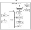
- FIG. 2 shows a circuit configuration of the head mounted display 100.
- the control unit 10 is a main processor that processes and outputs signals such as image signals and sensor signals, commands and data.
- the camera 110 supplies captured image data to the control unit 10.
- the display 30 is a liquid crystal display or the like, and receives an image signal from the control unit 10 and displays it.
- the communication control unit 40 transmits data input from the control unit 10 to the outside by wired or wireless communication via the network adapter 42 or the antenna 44.
- the communication control unit 40 also receives data from the outside via wired or wireless communication via the network adapter 42 or the antenna 44 and outputs the data to the control unit 10.
- the storage unit 50 temporarily stores data, parameters, operation signals, and the like processed by the control unit 10.
- the motion sensor 64 detects posture information such as the rotation angle and tilt of the head mounted display 100.
- the motion sensor 64 is realized by appropriately combining a gyro sensor, an acceleration sensor, a geomagnetic sensor, and the like.
- the external input / output terminal interface 70 is an interface for connecting peripheral devices such as a USB (Universal Serial Bus) controller.
- the external memory 72 is an external memory such as a flash memory.
- the control unit 10 can supply the image and audio data to the display 30 and headphones (not shown) and output them, or can supply the image and audio data to the communication control unit 40 and transmit them to the outside.
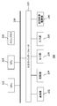
- FIG. 3 is a configuration diagram of the information processing system according to the present embodiment.
- the head mounted display 100 establishes communication with the information processing apparatus 200 through a communication protocol such as Bluetooth (registered trademark) protocol or IEEE 802.11 protocol via the antenna 44 of FIG.
- the information processing apparatus 200 may be further connected to a server via a network.
- the server may provide the information processing apparatus 200 with an online application such as a game that allows a plurality of users to participate via a network.
- the head mounted display 100 may be connected to a computer or a mobile terminal instead of the information processing apparatus 200.
- the information processing apparatus 200 basically receives the data of the images taken by the camera 110 of the head mounted display 100, performs a predetermined process, generates a display image, and transmits it to the head mounted display 100 as a frame. Repeat every time. Accordingly, various images such as AR and VR are displayed on the head mounted display 100 with a field of view corresponding to the orientation of the user's face.
- the final purpose of such a display can be variously considered such as a game, a virtual experience, and a video appreciation.
- FIG. 4 shows the internal circuit configuration of the information processing apparatus 200.
- the information processing apparatus 200 includes a CPU (Central Processing Unit) 222, a GPU (Graphics Processing Unit) 224, and a main memory 226. These units are connected to each other via a bus 230. An input / output interface 228 is further connected to the bus 230.
- CPU Central Processing Unit
- GPU Graphics Processing Unit
- the input / output interface 228 includes a communication unit 232 including a peripheral device interface such as USB and IEEE 1394, a network interface such as a wired or wireless LAN, a storage unit 234 such as a hard disk drive or a nonvolatile memory, a display device or a speaker (not shown).
- a communication unit 232 including a peripheral device interface such as USB and IEEE 1394, a network interface such as a wired or wireless LAN, a storage unit 234 such as a hard disk drive or a nonvolatile memory, a display device or a speaker (not shown).
- An output unit 236 that outputs image and audio data
- an input unit 238 that inputs data from an input device (not shown)
- a recording medium driving unit 240 that drives a removable recording medium such as a magnetic disk, an optical disk, or a semiconductor memory are connected. .
- the CPU 222 controls the entire information processing apparatus 200 by executing an operating system stored in the storage unit 234.
- the CPU 222 also executes various programs read from the removable recording medium and loaded into the main memory 226 or downloaded via the communication unit 232.
- the GPU 224 has a function of a geometry engine and a function of a rendering processor, and performs a drawing process according to a drawing command from the CPU 222.
- the main memory 226 includes a RAM (Random Access Memory) and stores programs and data necessary for processing.
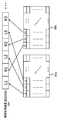
- FIG. 5 schematically shows a data structure when the head mounted display 100 transmits an image taken by the camera 110.
- the camera 110 is configured by a stereo camera
- a pair of a left viewpoint captured image 80a and a right viewpoint captured image 80b is acquired at a predetermined frame rate.
- the head mounted display 100 packetizes the acquired image data in a predetermined transmission unit in order from the upper left of the image so as to correspond to the scanning order of the image sensor, and transmits the packet to the information processing apparatus 200.
- L1, L2, L3,... From the upper left of the left viewpoint photographed image 80a, and R1, R2, R3,... From the upper left of the right viewpoint photographed image 80b are packetized.
- the data of each transmission unit is compression-coded in a predetermined format, and the data of the left viewpoint captured image 80a and the data of the right viewpoint captured image 80b are alternately transmitted. That is, data of transmission units L1, R1, L2, R2, L3, R3,... Are transmitted in this order as a data stream.
- the number of rows and columns of pixels that constitute each transmission unit is determined based on the compatibility with the encoding method used. Also, for simplicity in the illustrated example, both the area of the image of the transmission unit and the data size of the encoded image included in one packet are represented equally, but when adopting the variable length encoding method, Either of them can be unequal.
- FIG. 6 schematically shows a data structure of an image received from the head mounted display 100 by the information processing apparatus 200.
- the data of the left viewpoint captured image and the right viewpoint captured image are alternately transmitted in a predetermined transmission unit. Therefore, originally, data of transmission units L1, R1, L2, R2, L3, R3,... Is acquired as a data stream in this order as shown in the upper part of the figure.
- the information processing apparatus 200 decodes the data transmitted sequentially in this way and develops it in the buffer memory so as to be associated with the original position on the image plane, thereby capturing the original photographed image, that is, the left viewpoint.
- the image 82a and the captured image 82b at the right viewpoint are restored.
- packets may be lost during transmission depending on communication conditions.
- the fact that the transmission units R2 and L3 are not transmitted is indicated by shading.
- the restored captured images 82a and 82b are naturally incomplete.
- ARQ Automatic repeat-request
- ARQ is implemented in a communication protocol such as RTP (Real-time Transport Protocol) and TCP (Transmission Control Protocol) as one of error correction methods.
- RTP Real-time Transport Protocol
- TCP Transmission Control Protocol
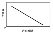
- FIG. 7 qualitatively represents the data loss rate with respect to the time allowed for the retransmission process when transmitting image data. As shown in the figure, as the allowable time is longer, there is a margin for individual retransmission processing, and the probability of handling multiple packet losses of the same data increases, resulting in a lower data loss rate. On the other hand, when it is assumed that some information processing is performed using a photographed image as in the present embodiment and an image that moves so as to correspond to an actual movement is displayed, the time allowed for data transmission is extremely high. short.
- the image data transmitted during that time should be utilized to the maximum so that image analysis can be performed properly.
- the location can be distinguished from others in image analysis and subsequent information processing.
- processing related to data transmission such as ARQ is controlled independently of other processing by a mutual communication mechanism.
- such a transmission parameter is organically linked to an analysis function implemented by an application such as a game, thereby improving the balance between immediacy including data transmission and processing accuracy.
- the allowable time can be adjusted from the viewpoint of processing accuracy, or the processing algorithm can be appropriately switched according to the data loss rate determined by the allowable time.
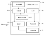
- FIG. 8 shows a functional block configuration of the head mounted display 100 in the present embodiment.
- the functional blocks shown in FIG. 9 and FIG. 9 to be described later can be realized by the various mechanisms shown in FIG. 2 and FIG. 4 in hardware, and the data analysis function loaded into the memory from a recording medium etc. in software It is realized by a program that exhibits various functions such as an image processing function. Therefore, it is understood by those skilled in the art that these functional blocks can be realized in various forms by hardware only, software only, or a combination thereof, and is not limited to any one.
- the head mounted display 100 performs data transmission / reception with the data acquisition unit 120 that acquires a captured image by the camera 110, an encoding unit 122 that encodes the captured image, a buffer 124 that temporarily stores the encoded data, and the information processing apparatus 200. It includes a communication unit 126 that is an interface, a retransmission control unit 128 that processes a retransmission request from the information processing apparatus 200, and a data output unit 130 that outputs a display image and the like.
- the data acquisition unit 120 includes the camera 110 and the control unit 10 shown in FIG. 2, and acquires image data obtained by photographing the visual field space at a predetermined frame rate.
- the camera 110 is configured by a stereo camera as shown in FIG. 1, the captured image is a pair of parallax images having a field of view corresponding to the left eye and the right eye of the user wearing the head mounted display 100.
- the present embodiment is not limited to this, and a single-view video may be shot with a monocular camera.
- the data acquisition unit 120 supplies the pixel value to the encoding unit 122 in order from the pixel for which the pixel value has been acquired.
- the encoding unit 122 includes the control unit 10 and the like, and compresses and encodes the captured image data acquired by the data acquisition unit 120 using a predetermined encoding method such as JPEG.
- the buffer 124 includes a storage unit 50, and temporarily stores the compressed and encoded captured image data in preparation for a retransmission request.
- the communication unit 126 includes the communication control unit 40, the antenna 44, and the like. The communication unit 126 packetizes the compression-encoded captured image data for each transmission unit and transmits the packetized data to the information processing apparatus 200. As shown in FIG. 5, the captured image can be transmitted with low latency by encoding in the order in which data was acquired by the image sensor, packetizing the data in transmission units, and transmitting.
- the communication unit 126 also receives a retransmission request for the packet issued when the information processing apparatus 200 detects a packet loss, and notifies the retransmission control unit 128 of the request.
- the retransmission control unit 128 reads transmission unit data corresponding to the packet designated in the retransmission request from the buffer 124 and supplies the data to the communication unit 126.
- the communication unit 126 packetizes and transmits the data again, retransmission processing for the lost packet is realized.
- the communication unit 126 further receives display image data and output audio data transmitted from the information processing apparatus 200 and supplies them to the data output unit 130.
- the data output unit 130 includes the control unit 10, the display 30, and the like, and performs display image display and audio output.
- FIG. 9 shows a functional block configuration of the information processing apparatus 200 in the present embodiment.
- the information processing apparatus 200 includes a communication unit 250 that is an interface for transmitting and receiving data to and from the head mounted display 100, a packet analyzing unit 252 that analyzes a packet transmitted from the head mounted display 100, and a retransmission that generates a retransmission request for a lost packet.
- the communication unit 250 includes the communication unit 232 and the CPU 222 shown in FIG. 4 and receives a packet made up of captured image data transmitted from the head mounted display 100.
- the communication unit 250 transmits the packet retransmission request generated by the retransmission request generation unit 254 and the display image and output audio data generated by the output data generation unit 266 to the head mounted display 100.
- the packet analysis unit 252 is configured by the CPU 222 and the like, sequentially acquires the packets transmitted from the head mounted display 100, and analyzes them. Specifically, a packet lost in data transmission is detected based on identification information (hereinafter referred to as “packet ID”) given to each packet. Further, the header information including the packet ID and the like are separated from the data body, and the latter is stored in the buffer 256 in association with the position on the image plane.
- packet ID identification information
- the packet analysis unit 252 notifies the retransmission request generation unit 254 of the packet ID.
- the retransmission request generation unit 254 is configured by the CPU 222 and the like, and generates a retransmission request including a lost packet ID.
- the retransmission request is transmitted to the head mounted display 100 via the communication unit 250.
- a retransmission request is issued by designating a packet corresponding to a transmission unit such as “R2” or “L3”.
- the retransmission request generation unit 254 may repeat the retransmission request until a lost packet can be acquired. However, if a predetermined allowable time elapses without acquiring the specified packet, it is determined as a timeout, and thereafter, the retransmission request for that packet is Not performed. Therefore, the retransmission request generation unit 254 holds the set value of the allowable time in the internal memory.
- the missing information generation unit 258 is configured by the CPU 222 and the like, and generates information (hereinafter referred to as “missing information”) related to data that could not be acquired even after the allowable time has elapsed.
- Missing information basically indicates how much data is missing at which position on the image. Therefore, the missing information generation unit 258 sequentially obtains information related to the missing transmission unit data from the packet analysis unit 252, and obtains the timing of expiration of the allowable time from the retransmission request generation unit 254, so that the data is finally obtained. Identify the missing part. Since the allowable time expires earlier in the transmission order, the missing information can be generated in synchronization with the processing start of the corresponding area. The generated missing information is sequentially supplied to the decoding unit 260.
- the decoding unit 260 includes the CPU 222 and the like, and sequentially reads out the data body from the buffer 256 and decodes it to restore the captured image.
- the packet analysis unit 252, the buffer 256, and the decoding unit 260 sequentially implement the data transition as shown in FIG. At this time, in the missing information acquired from the missing information generation unit 258, predetermined invalid data is substituted for the pixel that is the missing portion.
- the decoding unit 260 associates the restored captured image data with missing information and supplies the data to the image analysis unit 262.
- the image analysis unit 262 is configured by the CPU 222 and the like, and performs predetermined image analysis on the captured image data restored by the decoding unit 260.
- the analysis contents made here can be considered in various ways depending on the contents of information processing at a later stage, the purpose of photographing, the contents of display, and the like. For example, in order to acquire the position and orientation of the user's head, the above-described v-SLAM is performed, and in order to acquire the position of the subject in real space, stereo matching is performed using the left and right parallax images to generate a depth image. To do.
- a depth image is an image that represents the distance of the subject from the camera as the pixel value of the corresponding image on the captured image, and the corresponding point is extracted from the parallax image and is based on the principle of triangulation based on the parallax between the two. It is obtained by calculating the distance.
- 3D modeling of real objects in the subject space using depth images By modeling a real object as an object in a computational three-dimensional space, an AR in which a virtual object and the real object interact can be realized.
- an image of a real object having a predetermined shape or color may be detected by template matching, or a person or an object may be recognized based on details such as a face.
- the image analysis unit 262 refers to the missing information in such image analysis, and appropriately differentiates the processing content from other areas with respect to the location where data is lost due to packet loss. For example, a portion where data is missing is excluded from the region to be analyzed, such as a corresponding point search target for depth image generation and a template matching target for object detection. Alternatively, analysis may be performed in the same manner as described above, and a result regarding a location where data is missing may not be output, or additional information indicating that the accuracy of the location may be low may be generated.
- the “location where data is missing” may be a location where there is no true data, or a region where the missing rate is higher than a predetermined threshold when the image plane is divided according to a predetermined rule.
- the image analysis unit 262 by allowing the image analysis unit 262 to recognize the “location where data is missing” and to differentiate the analysis processing itself or the use form of the analysis results from others, the accuracy of processing due to data loss can be improved. Deterioration can be minimized.
- the information processing unit 264 is configured by the CPU 222 and the like, and performs predetermined information processing such as a game using the result of image analysis. As described above, the content is not particularly limited.
- the information processing unit 264 may treat the analysis result of the portion indicated by the image analysis unit 262 as being different from others because the analysis accuracy may be low due to missing data. For example, an object including an edge in such a part is excluded from the calculation target, or an object is not drawn in such a part. By doing so, it is possible to prevent the deterioration of the analysis accuracy of the partial region from being propagated to other processes, or to guide the user's line of sight to another location.
- the output data generation unit 266 includes a CPU 222, a GPU 224, and the like, and generates image data to be displayed on the head mounted display 100 and audio data to be output as a result of processing by the information processing unit 264. For example, a virtual world whose field of view changes according to the movement of the user's head is generated, or voice data in the virtual world is generated. The generated data is sequentially transmitted to the head mounted display 100 via the communication unit 250.
- FIG. 10 shows a data structure example of a packet transmitted from the head mounted display 100 to the information processing apparatus 200 in the present embodiment.
- the illustrated packet 90 represents one of the packet sequences shown in the upper part of FIGS. 5 and 6, whereby data for one transmission unit of the captured image is transmitted.
- the packet 90 includes a packet information unit 92 and an image data unit 94.
- the packet information unit 92 includes so-called header information such as “packet ID”, “packet length”, “transmission time”,.
- Packet ID is identification information uniquely given to all packets generated for one frame of a captured image. For example, it may be an ascending number such as “0”, “1”, “2”,... Given in raster order to the transmission unit, or may be a two-dimensional position coordinate on the image plane. Alternatively, it may be the start address of each transmission unit when the image is expanded in the memory. In addition, as shown in FIGS. 5 and 6, when the left and right viewpoint captured images are transmitted alternately, an identifier for identifying which image packet is further added.
- Packet length is the data size of the packet 90.
- Transport time is a time stamp indicating the time when the packet 90 is transmitted from the head mounted display 100.
- the packet information unit 92 may appropriately include other information depending on the communication protocol employed.
- the image data unit 94 data of a transmission unit of a captured image, which is compression-encoded by the encoding unit 122 of the head mounted display 100, is stored.
- the packet analysis unit 252 divides the transmitted packet 90 into a packet information unit 92 and an image data unit 94, and stores the latter data in the buffer 256 in association with the position on the image.
- the position of each data on the image can be specified based on the packet ID by sharing information related to the rule for assigning the packet ID with the head mounted display 100. Therefore, the data in the packet that can be acquired without loss is stored in the buffer 256 in association with the position on the image.
- the packet analysis unit 252 also detects packet loss by checking the packet ID of the packet information unit 92 in the order of transmission. For example, when an ascending number is assigned as the packet ID, the omission can be detected by comparing the packet arrival order with the packet ID.
- the packet analysis unit 252 notifies the retransmission request generation unit 254 of the ID of the lost packet detected in this manner, thereby generating a retransmission request.
- the lost packet information or the latest information related to the position of the data on the image is also notified to the missing information generation unit 258 so that missing information is generated when the allowable time expires.
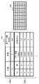
- FIG. 11 illustrates a data structure of missing information generated by the missing information generation unit 258 of the information processing apparatus 200.
- the address of an area where data corresponding to a lost packet is to be stored in the image data storage area 302 included in the buffer 256 is directly shown. That is, the missing information 300 is composed of the “start address” and “data length” of the missing part.
- the missing portion is recognized with the data transmitted in one packet, that is, the transmission unit as the minimum granularity. When packets are lost continuously, the numerical value of “data length” in the missing information 300 increases.
- the missing information generation unit 258 generates missing information 300 by deriving a set (head address, data length) from the ID of such a lost packet. Then, referring to the missing information, the decoding unit 260 substitutes invalid data as a pixel value, or the image analysis unit 262 performs analysis by differentiating from other data.
- FIG. 12 shows another example of the data structure of the missing information generated by the missing information generation unit 258 of the information processing apparatus 200.
- the data missing rate is shown for each block obtained by dividing the image plane.
- the missing information 304 includes header information 306a and a missing information body 306b.
- the header information 306a is composed of “number of rows” and “number of columns” of blocks obtained by equally dividing the image plane 308, and “total data length” of the image.
- the image plane 308 is divided into 6 rows and 8 columns.
- the total data length is 1 Mbyte.
- the number of divisions of the image plane is determined according to the analysis content and the characteristics of the captured image.
- the missing information body 306b is composed of the coordinates of the block composed of the “row” number and the “column” number, the “data length” of each block, and the “missing rate” of the data.
- the row number and the column number represent one block as a pair.
- the row numbers range from 0 to 5 and the column numbers range from 0 to 7.
- the data length of the block represents the size of the compression encoded data included in each block.
- the missing rate represents the proportion of data missing in the block. For example, a block of 0 rows and 0 columns indicates that 10% of 20000 bytes of data, that is, 2000 bytes of data is missing.
- the missing information shown in FIG. 11 directly represents the address of the part where the data is missing, so the analysis process can be differentiated with a finer granularity, while the number of entries increases as the intermittent missing increases.
- the data size of missing information increases.
- the missing information 304 in FIG. 12 can make the data size of missing information constant by grasping the degree of missing in units of regions of a predetermined area. Therefore, the format shown in the figure is advantageous when information with fine granularity is not important, such as when a low resolution image is used for image analysis.
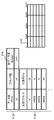
- FIG. 13 shows still another example of the data structure of missing information generated by the missing information generation unit 258 of the information processing apparatus 200.
- This example shows the data loss rate for each block obtained by dividing the image data as in the case of FIG. 12, but the size of the encoded data instead of the area on the image is used as a block division criterion. Is fixed. That is, as shown in the image data storage area 314, the addresses are equally divided on the storage area.
- the missing information 310 includes header information 312a and a missing information body 312b.
- the header information 312a is composed of a “data length” of one block, which is a division unit, a “number of blocks” divided as such, and a “total data length” of the image.
- the storage area 314 is divided into 24 blocks as a result of dividing the image data of 240 kbytes every 10 kbytes.
- the data length of the division unit is determined depending on the analysis content and the characteristics of the captured image.
- the missing information body 312b is composed of a “start address” of each block and a “missing rate” of data in each block. For example, it is indicated that 20% of 10 kbytes of data, that is, 2000 bytes of data is missing in a block whose head address is “0”.
- the image data storage area 314 is associated with the image plane, so the data loss rate of each block in the storage area indicates the data loss rate of the corresponding area of the image plane. .
- the degree of omission is expressed with a granularity larger than the granularity of the transmission unit transmitted in one packet
- the size of the omission information can be fixed regardless of the omission situation.
- variable length coding by defining the division unit by the data size, the area on the image corresponding to one block becomes smaller as the compressed data size becomes larger. Therefore, the data missing situation can be reflected in the analysis process in a finer unit as the image configuration is more complicated such as including a high frequency component.
- the missing information shown in FIGS. 11 to 13 has characteristics as described above, the structure of the space to be imaged, the content of the image analysis to be performed, the resolution of the image used for it, the accuracy required for the analysis, and the memory capacity Select the optimal format according to the hardware characteristics such as processing performance. For example, when it is necessary to extract finer features such as face recognition, the format shown in FIG. 11 is used. When roughly modeling the surface of a table in the subject space, the format shown in FIGS. 12 and 13 is used. It is conceivable to generate missing information.
- a retransmission request for a lost packet in a predetermined allowable time is made, and missing information is generated for a portion where data could not be obtained in such a manner.
- the upper limit of the allowable time is a time during which a shift in the movement of the image to be displayed is not recognized.
- FIG. 7A illustrates a change in analysis accuracy with respect to a change in data loss rate
- FIG. 7B illustrates a change in data loss rate with respect to a change in time allowed for a retransmission request, as in FIG.
- the change in the analysis accuracy is relatively small as from A1 to A2. Even if the analysis accuracy is A2, if the subsequent information processing and display are not greatly affected, even if the missing rate is D2, it is allowed.
- FIG. 15 shows a functional block configuration of an information processing apparatus having a function of adjusting the retransmission allowable time of a lost packet depending on the accuracy of image analysis. Note that blocks having the same functions as those of the information processing apparatus 200 illustrated in FIG. 9 are denoted by the same reference numerals, and description thereof will be omitted as appropriate.
- the information processing apparatus 200a includes a communication unit 250, a packet analysis unit 252, a buffer 256, a missing information generation unit 258, a decoding unit 260, an information processing unit 264, and an output data generation unit 266, similar to the information processing device 200 of FIG. .
- the information processing apparatus 200a further includes a retransmission request generation unit 254a, an image analysis unit 262a, and a processing condition adjustment unit 268.
- the basic functions of the retransmission request generation unit 254a and the image analysis unit 262a are the same as those of the retransmission request generation unit 254 and the image analysis unit 262 of the information processing apparatus 200 illustrated in FIG. However, the image analysis unit 262a feeds back the accuracy of the image analysis processing performed by itself to the processing condition adjustment unit 268.
- the processing condition adjustment unit 268 associates the accuracy of the processing with the missing data information, and adjusts the set value of the allowable time so as to allow the missing rate within a range in which the required accuracy is maintained.
- the retransmission request generation unit 254a accepts such adjustment of the allowable time.
- the processing condition adjustment unit 268 decreases the allowable time in the direction of L2 within the range of the missing rate where the accuracy does not fall below A2. . For example, at a new frame reception timing, the set value of the allowable time is lowered by a predetermined step size ⁇ L, and a retransmission request is performed within the allowable time. Although the data loss rate increases as the allowable time decreases, if the accuracy of the new frame image acquired in this way is not less than A2, the allowable time is further reduced. By repeating this until the accuracy reaches A2, the shortest allowable time that can maintain the required accuracy is obtained.
- such adjustment processing can be performed not only at the time of development or manufacture of the information processing apparatus or the head mounted display but also at the time of system operation by the user.
- the minimum allowable time for maintaining appropriate accuracy depends on hardware such as the sensitivity of the image sensor of the camera, data correction processing inside the camera, encoding processing, communication environment, and processing performance of the information processing device. It also depends on the content of analysis, ambient brightness, shooting conditions, and the amount and color of objects in the subject space. This is because each graph shown in FIG. 14 changes under these conditions. Therefore, by optimizing the allowable time at various timings, it is possible to optimize the transmission environment while minimizing the influence on the processing accuracy.
- the “analysis accuracy” may be any index indicating the accuracy of image analysis, and may not be a numerical value obtained continuously as shown in FIG.
- the boundary may not be given numerically.
- two events such as whether or not a real object such as a hand that should be detected originally has been detected may be set as “analysis accuracy”.
- the transition between these events is a boundary, and the shortest allowable time may be obtained in a state where the real object is detected.
- the actually set allowable time may be a value obtained by adding a predetermined margin to the time acquired in this way.
- the image analysis is a generation of a depth image, it may be two events such as whether or not corresponding points are detected, or may be a numerical value such as an image average of similarity when corresponding points are detected.
- such analysis accuracy may be acquired as a distribution on the image plane.
- the allowable time can be adjusted more finely according to information such as where the analysis accuracy has deteriorated. For example, even if the accuracy is lower than the lower limit at the edge of the less important image, if the accuracy is maintained at the more important image center or the area where the tracking target exists, the allowable time is further shortened. It becomes possible.
- the allowable time is optimized in this way, various processing conditions in the head mounted display 100 may be adjusted accordingly.
- FIG. 16 shows a functional block configuration of the head mounted display 100 having a function of adjusting an internal processing condition according to a retransmission allowable time of a lost packet.
- the head mounted display 100a includes a data acquisition unit 120, a buffer 124, a retransmission control unit 128, and a data output unit 130, similar to the head mounted display 100 of FIG.
- the head mounted display 100a further includes an encoding unit 122a, a communication unit 126a, and a processing condition adjustment unit 132.
- the basic functions of the encoding unit 122a and the communication unit 126a are the same as those of the encoding unit 122 and the communication unit 126 shown in FIG. However, in this example, the parameters used for compression encoding are adjusted according to the packet retransmission allowable time. For this reason, the retransmission request generation unit 254a of the information processing device 200 transmits information on the allowable time finally determined by the processing condition adjustment unit 268 to the head mounted display 100a, and the communication unit 126a of the head mounted display 100a transmits it. Receive. Then, the processing condition adjustment unit 132 determines an encoding parameter according to the permissible time and sets it in the encoding unit 122a.
- the processing condition adjustment unit 132 adjusts the compression rate, for example. Qualitatively, in an unfavorable situation where analysis accuracy cannot be obtained unless the allowable time is increased and the data loss rate is reduced, the compression rate is increased. Thus, if the size is reduced, the number of packets transmitted per frame is reduced, and the number of packets to be retransmitted can be reduced even with the same loss rate. If the allowable time is adjusted again under such conditions, the allowable time may be reduced.
- the encoding method itself may be switched to one that has a small compression rate and little deterioration in image quality. Thereby, the processing load for encoding in the head mounted display 100a can be suppressed.
- the head-mounted display 100a is not supplied with a wired power supply, the reduction in processing load also leads to an improvement in battery duration by reducing power consumption.
- the processing condition adjustment unit 132 stores information in which an allowable time is associated with an encoding parameter or an encoding method in an internal memory, and a process set according to the allowable time transmitted from the information processing apparatus 200a. After specifying the conditions, the encoding unit 122a is notified.
- the encoding unit 122a performs compression encoding of the captured image under the notified conditions.
- the adjustment target by the processing condition adjustment unit 132 is not limited to the encoding parameter and the encoding method.
- the processing condition adjustment unit 132 there The resolution of the generated image or the resolution of the image to be transmitted to the information processing apparatus 200 may be switched according to the adjusted allowable time.
- the longer the permissible time after adjustment that is, the situation in which the analysis accuracy cannot be obtained unless the permissible time is lengthened and the data loss rate is reduced, the lower resolution image data is transmitted.
- the number of packets per frame can be reduced and the data loss rate can be suppressed. If the allowable time is adjusted again, the allowable time may be reduced.
- the measurement value of illuminance for adjustment of the allowable time in the information processing apparatus 200a by using the fact that the brighter the surroundings, the easier the image analysis accuracy is obtained.
- an illuminance sensor (not shown) is provided in the head mounted display 100 and the measured value is transmitted to the information processing apparatus 200.
- the information processing apparatus 200 adjusts the allowable time so as to decrease as the obtained illuminance increases.
- the optimum allowable time may be obtained from various viewpoints.
- the permissible time for the retransmission processing described so far has been set in the communication protocol and has been independent of the application. By making it possible to adjust this setting based on the accuracy of image analysis introduced by an application, it is possible to provide a transmission mode that can flexibly cope with hardware updates and changes in imaging environment. On the other hand, as a reverse approach, the image analysis algorithm may be switched according to the allowable time set by the communication protocol.
- an allowable time is given in FIG. 14B
- the analysis algorithm is switched to such that the graph of FIG. 14A showing sufficient analysis accuracy is obtained with the data missing rate corresponding thereto.
- An algorithm that can obtain analysis accuracy even when the missing rate is low is qualitatively considered an algorithm with low processing sensitivity. For example, by switching the edge detection filter from the Sobel filter to the Prewitt filter and the Roberts filter, the influence of the missing data portion can be suppressed, and a certain degree of accuracy can be maintained even if the allowable time is not sufficient.
- the allowable time is relatively long, the data loss rate can be kept low, and a more accurate result can be obtained by using a highly sensitive algorithm.
- the processing condition adjustment unit 268 of the information processing device 200a holds information in which the allowable time and the analysis algorithm are associated with each other in an internal memory, and an algorithm corresponding to the allowable time set in the retransmission request generation unit 254a. After the identification, the image analysis unit 262a is notified. The image analysis unit 262a analyzes the captured image using the notified algorithm. In this way, even if the communication protocol and hardware specifications are changed or upgraded, the influence of the change can be prevented from affecting image analysis, and thus information processing and display contents.
- the analysis algorithm may be switched not only in accordance with the allowable time given as a fixed value but also in the allowable time adjusted according to the environment.
- the allowable time can be adjusted according to the illuminance, and an appropriate algorithm can be selected for the adjusted allowable time.
- the information processing apparatus 200a acquires various environment-dependent parameters that determine the shooting conditions such as exposure, aperture value, shutter speed, white balance, etc., in which an automatic adjustment function is implemented in the camera 110, and is allowed accordingly.
- An appropriate algorithm may be selected after adjusting the time.
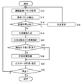
- FIG. 17 is a flowchart illustrating a processing procedure in which the information processing apparatus generates output data based on captured image data in the present embodiment.
- the figure shows the operation of the information processing apparatus 200a including the allowable time adjustment function described in FIG. 15, but assuming the information processing apparatus 200 not including the adjustment function shown in FIG.
- the process of S24 is omitted.
- the communication unit 250 of the information processing device 200a acquires a packet including data of the first frame of the captured image from the head mounted display 100 (S10). Since the data is gradually sent in transmission units as described above, the process of S10 is actually performed in parallel with the subsequent process. The same applies to the retransmission request in S16 and the missing information generation process in S18.
- the packet analysis unit 252 detects the lost packet by storing the captured image data in the buffer 256 in the order in which the packets are acquired and comparing the packet ID with the transmission order (S12).
- the retransmission request generation unit 254a starts measuring the elapsed time for retransmission of the packet at the timing when the packet loss is detected. If the elapsed time is within the allowable retransmission time (Y in S14), the retransmission request generation unit 254a generates a retransmission request for the packet and transmits it to the head mounted display 100 via the communication unit 250 (S16). For lost packets, the processes of S10, S12, and S16 are repeated until the allowable time expires.
- the missing information generation unit 258 generates missing information indicating that data corresponding to the packet is missing (S18). While referring to the missing information, the decoding unit 260 and the image analysis unit 262a perform a decoding process and an analysis process by distinguishing a portion where data is missing in the image from others (S20). Specifically, the decoding unit 260 acquires the captured image data from the buffer 256 and decodes it, and substitutes invalid data into the pixel value of the location where the data is missing.
- the image analysis unit 262a excludes a portion where the data is missing from the analysis target and the output target of the result, or generates additional information indicating that the accuracy of the analysis result related to the portion may be low. . Note that only one of the decoding unit 260 and the image analysis unit 262a may deal with the data loss as described above depending on the format of the missing information, the content of the image analysis, and the like.
- the processing condition adjustment unit 268 adjusts the setting in the retransmission request generation unit 254a so as to shorten the allowable time for retransmission processing (S24). ).
- the accuracy has reached the predetermined lower limit (Y in S22)
- the allowable time is not adjusted.
- the analysis accuracy may be optimized by adjusting the allowable time in the extending direction. In this case, however, it is necessary to separately set an upper limit of the allowable time from the viewpoint of latency from shooting to display.
- the information processing unit 264 performs information processing using the result of image analysis or the like, and the output data generation unit 266 generates the result as output data such as a display image or sound (S26).
- the output data is transmitted from the communication unit 250 to the head mounted display 100 and output. If it is not necessary to stop the process due to input from the user or the like, the processes of S10 to S26 are repeated for subsequent frames of the captured image (N in S28). When it is necessary to stop the processing, all the processing is finished (Y in S28).
- missing information that associates the data that could not be acquired with the position on the image is generated. Then, in image analysis and information processing, the point where data is missing is differentiated from the others and processed. As a result, in various processes until the output data is generated, the processing result of the portion where the data is missing is handled in the same manner as the result of other areas, and it is possible to prevent the entire output result from being adversely affected. .
- the allowable time, analysis algorithm, encoding processing parameters, etc. are adjusted. For example, by adjusting in a direction to reduce the allowable time within a range in which accuracy is guaranteed, it is possible to reduce the influence on the result and increase the processing speed.
- the allowable time adjusted in this way reflects the characteristics of the captured image, such as difficulty in obtaining the analysis accuracy. It is possible to realize an optimal transmission form according to the above.
- switching the analysis algorithm according to the permissible time enables processing under conditions that provide the best results for a given environment including the communication environment.
- the present invention can be used for various information processing devices such as game devices, image processing devices, personal computers, display devices such as imaging devices and head mounted displays, and information processing systems including them.
Landscapes
- Engineering & Computer Science (AREA)
- Signal Processing (AREA)
- Multimedia (AREA)
- Theoretical Computer Science (AREA)
- Computer Networks & Wireless Communication (AREA)
- Physics & Mathematics (AREA)
- General Physics & Mathematics (AREA)
- Databases & Information Systems (AREA)
- Computer Vision & Pattern Recognition (AREA)
- Quality & Reliability (AREA)
- General Engineering & Computer Science (AREA)
- Human Computer Interaction (AREA)
- Artificial Intelligence (AREA)
- Evolutionary Computation (AREA)
- General Health & Medical Sciences (AREA)
- Medical Informatics (AREA)
- Software Systems (AREA)
- Computing Systems (AREA)
- Health & Medical Sciences (AREA)
- Two-Way Televisions, Distribution Of Moving Picture Or The Like (AREA)
- Processing Or Creating Images (AREA)
- Detection And Prevention Of Errors In Transmission (AREA)
- Communication Control (AREA)
Abstract
情報処理装置200aにおいて通信部250は、無線通信により撮影画像のデータストリームを取得する。パケット解析部252は損失したパケットを検出し、再送要求生成部254aは所定の許容時間内でパケットの再送要求を発行する。画像解析部262aは撮影画像のデータを解析する。情報処理部264、出力データ生成部266は、解析結果を利用して情報処理を行い出力データを生成する。処理条件調整部268は、画像解析部262aにおける解析結果に基づき、再送要求生成部254aによる再送要求の許容時間を調整する。
Description
本発明は、撮影画像を利用して情報処理を行う情報処理装置、情報処理システム、およびそれらでなされる情報処理方法に関する。
ユーザをビデオカメラで撮影し、その像を別の画像で置換してディスプレイに表示するゲームが知られている(例えば、特許文献1参照)。また、ビデオカメラで撮影された口や手の動きをアプリケーションの操作指示として受け取るユーザインターフェースシステムも知られている。このように、実世界を撮影しその動きに反応する仮想世界を表示させたり、何らかの情報処理を行ったりする技術は、小型の携帯端末からレジャー施設まで、その規模によらず幅広い分野で利用されている。
その一例として、ヘッドマウントディスプレイにパノラマ映像を表示し、ヘッドマウントディスプレイを装着したユーザが頭部を回転させると視線方向に応じたパノラマ画像が表示されるようにしたシステムも開発されている。ヘッドマウントディスプレイを利用することで、映像への没入感を高めたり、ゲームなどのアプリケーションの操作性を向上させたりすることができる。また、ヘッドマウントディスプレイを装着したユーザが物理的に移動することで、映像として表示された空間内を仮想的に歩き回ることのできるウォークスルーシステムも開発されている。
臨場感のある画像表現を実現したり、情報処理を高精度に行ったりするためには、撮影画像の解像度やフレームレートを高くすることが望ましい。一方、そのようにして扱うべきデータサイズが増えると、データ伝送や画像解析の負荷が増え、画像表示までに要する時間が増加する。その結果、実際の動きと表示にずれが生じるなどして、ユーザに違和感を与えることもあり得る。また伝送帯域を圧迫することによりデータの欠落が生じやすくなり、画像解析の精度がかえって悪化することもあり得る。
本発明はこうした課題に鑑みてなされたものであり、その目的は、撮影画像データの伝送および解析を伴う情報処理において、即時性を損なわずに良好な処理結果を取得できる技術を提供することにある。
上記課題を解決するために、本発明のある態様は情報処理装置に関する。この情報処理装置は、撮像装置と通信を確立し撮影画像のデータを取得する通信部と、撮影画像のデータのうち取得されなかった部分について、設定された許容時間内に撮像装置に再送要求を発行する再送要求生成部と、取得されたデータを用いて撮影画像の解析を行う画像解析部と、解析の結果に基づき出力データを生成して出力する出力データ生成部と、解析の結果に基づき、許容時間の設定値を調整する処理条件調整部と、を備えることを特徴とする。
本発明の別の態様も情報処理装置に関する。この情報処理装置は、撮像装置と通信を確立し撮影画像のデータを取得する通信部と、撮影画像のデータのうち取得されなかった部分について、設定された許容時間内に撮像装置に再送要求を発行する再送要求生成部と、許容時間の設定値に応じて撮影画像の解析のアルゴリズムを切り替える処理条件調整部と、取得されたデータを用いて、アルゴリズムで撮影画像の解析を行う画像解析部と、解析の結果に基づき出力データを生成して出力する出力データ生成部と、を備えることを特徴とする
本発明のさらに別の態様は情報処理システムに関する。この情報処理システムは、撮像装置と、当該撮像装置と通信を確立し撮影画像を用いた情報処理を実施する情報処理装置と、を含み、情報処理装置は、撮影画像のデータを取得し情報処理装置へ送信する通信部と、撮影画像のデータのうち取得されなかった部分について、設定された許容時間内に撮像装置に再送要求を発行する再送要求生成部と、取得されたデータを用いて撮影画像の解析を行う画像解析部と、解析の結果に基づき出力データを生成して出力する出力データ生成部と、解析の結果に基づき、許容時間の設定値を調整する処理条件調整部と、を備え、撮像装置は、撮影画像のデータを取得し情報処理装置へ送信する通信部と、情報処理装置から発行された再送要求に応じて該当データの再送を制御する再送制御部と、情報処理装置において調整された許容時間の設定値を取得し、当該設定値に基づき撮影画像のデータ処理の態様を変化させる処理条件調整部と、を備えることを特徴とする。
本発明のさらに別の態様は撮像装置に関する。この撮像装置は、撮影画像のデータを取得するデータ取得部と、情報処理装置と通信を確立し撮影画像のデータを送信する通信部と、情報処理装置が設定された許容時間内に発行した、撮影画像のデータのうち取得されなかった部分の再送要求に応じて、該当データの再送を制御する再送制御部と、情報処理装置において調整された許容時間の設定値を取得し、当該設定値に基づき撮影画像のデータ処理の態様を変化させる処理条件調整部と、を備えることを特徴とする。
本発明のさらに別の態様はヘッドマウントディスプレイに関する。このヘッドマウントディスプレイは、上述の撮像装置と、情報処理装置から、撮影画像に基づき生成された表示画像のデータを取得し表示するディスプレイと、を備えたことを特徴とする。
本発明のさらに別の態様は情報処理方法に関する。この情報処理方法は情報処理装置が、撮像装置と通信を確立し撮影画像のデータを取得するステップと、撮影画像のデータのうち取得されなかった部分について、設定された許容時間内に撮像装置に再送要求を発行するステップと、取得されたデータを用いて撮影画像の解析を行うステップと、解析の結果に基づき出力データを生成して出力するステップと、解析の結果に基づき、許容時間の設定値を調整するステップと、を含むことを特徴とする。
本発明のさらに別の態様も情報処理方法に関する。この情報処理方法は情報処理装置が、撮像装置と通信を確立し撮影画像のデータを取得するステップと、撮影画像のデータのうち取得されなかった部分について、設定された許容時間内に撮像装置に再送要求を発行するステップと、取得されたデータを用いて撮影画像の解析を行うステップと、解析の結果に基づき出力データを生成して出力するステップと、を含み、解析を行うステップは、許容時間の設定値に応じて、用いるアルゴリズムが切り替えられることを特徴とする。
なお、以上の構成要素の任意の組合せ、本発明の表現を方法、装置、システム、コンピュータプログラム、データ構造、記録媒体などの間で変換したものもまた、本発明の態様として有効である。
本発明によれば、撮影画像データの伝送および解析を伴う情報処理において、即時性を損なわずに良好な処理結果を取得できる。
本実施の形態では、撮影装置によって撮影された画像を用いて情報処理を行い、その結果を即時表示するシステムにおいて、伝送時にデータが欠落しても最大限のパフォーマンスを発揮できるようにする。この限りにおいて撮像装置や表示装置の形態は特に限定されないが、ここではカメラを備えたヘッドマウントディスプレイを例に説明する。ヘッドマウントディスプレイによって撮影された画像を利用して、それを装着したユーザの頭部の動きに対応するように視野が変化する画像を描画し表示させるのは、時間的な制約の厳しさの観点で好適な例である。ただし撮像装置と表示装置が別の筐体を有していても、本実施の形態を同様に適用できる。
図1は、本実施の形態におけるヘッドマウントディスプレイの外観形状の例を示している。この例においてヘッドマウントディスプレイ100は、出力機構部102および装着機構部104で構成される。装着機構部104は、ユーザが被ることにより頭部を一周し装置の固定を実現する装着バンド106を含む。装着バンド106はユーザの頭囲に合わせて長さの調節が可能な素材または構造とする。例えばゴムなどの弾性体としてもよいし、バックルや歯車などを利用してもよい。
出力機構部102は、ヘッドマウントディスプレイ100をユーザが装着した状態において両眼を覆うような形状の筐体108を含み、内部には装着時に目に正対するように表示パネルを備える。表示パネルは液晶パネルや有機ELパネルなどで実現する。筐体108内部にはさらに、ヘッドマウントディスプレイ100の装着時に表示パネルとユーザの目との間に位置し、広い視野で画像が視認されるようにする一対のレンズを備える。またヘッドマウントディスプレイ100はさらに、装着時にユーザの耳に対応する位置にスピーカーやイヤホンを備えてよい。
ヘッドマウントディスプレイ100は、出力機構部102の前面にカメラ110を備える。カメラ110はCCD(Charge Coupled Device)またはCMOS(Complementary Metal Oxide Semiconductor)等の撮像素子を備え、ヘッドマウントディスプレイ100を装着したユーザの顔の向きに対応する視野で、実空間を所定のフレームレートで撮影する。なおカメラ110はヘッドマウントディスプレイ100の前面に1つのみ設けられてもよいし、既知の間隔を有するように2つのカメラを左右に配置したステレオカメラとしてもよい。またカメラ110の配置は特に限定されない。
カメラ110が撮影した画像は、ヘッドマウントディスプレイ100における表示画像の少なくとも一部として使用できるほか、仮想世界の生成に必要な画像解析のための入力データとすることもできる。例えば撮影画像をそのまま表示画像とすれば、ユーザは目の前の実空間を直接見ているのと同じ状態となる。また、視野内にある机などの実物体上に滞留したり実物体とインタラクションしたりするオブジェクトを撮影画像上に描画して表示画像とすることにより、AR(Augmented Reality:拡張現実)を実現できる。
さらに、ヘッドマウントディスプレイ100を装着したユーザの頭部の位置や姿勢を撮影画像から特定し、それに対応するように視野を変化させて仮想世界を描画することによりVR(Virtual Reality:仮想現実)も実現できる。撮影画像からカメラの位置や姿勢を推定する技術には、v-SLAM(Visual Simultaneous Localization And Mapping)などの一般的な技術を適用できる。頭部の回転角や傾きは、ヘッドマウントディスプレイ100に内蔵または外付けされたモーションセンサによって計測してもよい。撮影画像の解析結果とモーションセンサの計測値を相補完的に利用してもよい。
図2は、ヘッドマウントディスプレイ100の回路構成を示している。制御部10は、画像信号、センサ信号などの信号や、命令やデータを処理して出力するメインプロセッサである。カメラ110は撮影画像のデータを制御部10に供給する。ディスプレイ30は液晶ディスプレイなどであり、制御部10から画像信号を受け取り表示する。
通信制御部40は、ネットワークアダプタ42またはアンテナ44を介して、有線または無線通信により、制御部10から入力されるデータを外部に送信する。通信制御部40は、また、ネットワークアダプタ42またはアンテナ44を介して、有線または無線通信により、外部からデータを受信し、制御部10に出力する。記憶部50は、制御部10が処理するデータやパラメータ、操作信号などを一時的に記憶する。
モーションセンサ64は、ヘッドマウントディスプレイ100の回転角や傾きなどの姿勢情報を検出する。モーションセンサ64は、ジャイロセンサ、加速度センサ、地磁気センサなどを適宜組み合わせて実現される。外部入出力端子インターフェース70は、USB(Universal Serial Bus)コントローラなどの周辺機器を接続するためのインターフェースである。外部メモリ72は、フラッシュメモリなどの外部メモリである。制御部10は、画像や音声データをディスプレイ30や図示しないヘッドホンに供給して出力させたり、通信制御部40に供給して外部に送信させたりすることができる。
図3は、本実施の形態に係る情報処理システムの構成図である。ヘッドマウントディスプレイ100は、図2のアンテナ44等を介して、Bluetooth(登録商標)プロトコルやIEEE802.11プロトコルなどの通信プロトコルにより情報処理装置200と通信を確立する。情報処理装置200は、さらにネットワークを介してサーバに接続されてもよい。その場合、サーバは、複数のユーザがネットワークを介して参加できるゲームなどのオンラインアプリケーションを情報処理装置200に提供してもよい。ヘッドマウントディスプレイ100は、情報処理装置200の代わりに、コンピュータや携帯端末に接続されてもよい。
情報処理装置200は基本的に、ヘッドマウントディスプレイ100のカメラ110が撮影した画像のデータを順次受信し、所定の処理を実施したうえ表示画像を生成してヘッドマウントディスプレイ100に送信する処理をフレームごとに繰り返す。これによりヘッドマウントディスプレイ100には、ユーザの顔の向きに応じた視野で、ARやVRなど様々な画像が表示される。なおこのような表示の最終目的は、ゲーム、仮想体験、動画鑑賞など様々に考えられる。
図4は情報処理装置200の内部回路構成を示している。情報処理装置200は、CPU(Central Processing Unit)222、GPU(Graphics Processing Unit)224、メインメモリ226を含む。これらの各部は、バス230を介して相互に接続されている。バス230にはさらに入出力インターフェース228が接続されている。
入出力インターフェース228には、USBやIEEE1394などの周辺機器インターフェースや有線又は無線LANなどのネットワークインターフェースからなる通信部232、ハードディスクドライブや不揮発性メモリなどの記憶部234、図示しない表示装置やスピーカーなどへ画像や音声のデータを出力する出力部236、図示しない入力装置などからデータを入力する入力部238、磁気ディスク、光ディスクまたは半導体メモリなどのリムーバブル記録媒体を駆動する記録媒体駆動部240が接続される。
CPU222は、記憶部234に記憶されているオペレーティングシステムを実行することにより情報処理装置200の全体を制御する。CPU222はまた、リムーバブル記録媒体から読み出されてメインメモリ226にロードされた、あるいは通信部232を介してダウンロードされた各種プログラムを実行する。GPU224は、ジオメトリエンジンの機能とレンダリングプロセッサの機能とを有し、CPU222からの描画命令に従って描画処理を行う。メインメモリ226はRAM(Random Access Memory)により構成され、処理に必要なプログラムやデータを記憶する。
図5は、ヘッドマウントディスプレイ100が、カメラ110が撮影した画像を送信する際のデータ構造を模式的に示している。カメラ110をステレオカメラで構成した場合、左視点の撮影画像80aと右視点の撮影画像80bとの対が所定のフレームレートで取得される。ヘッドマウントディスプレイ100は撮像素子の走査順に対応するように、画像の左上から順に、取得された画像データを所定の送信単位でパケット化して情報処理装置200に送信する。
同図は、左視点の撮影画像80aの左上からL1、L2、L3、・・・、右視点の撮影画像80bの左上からR1、R2、R3、・・・、なる送信単位でパケット化されることを表している。各送信単位のデータは、所定のフォーマットで圧縮符号化され、左視点の撮影画像80aのデータ、右視点の撮影画像80bのデータが交互に送出される。すなわち送信単位L1、R1、L2、R2、L3、R3、・・・・のデータが、この順にデータストリームとして送信される。
なお各送信単位を構成する画素の行数、列数は、採用する符号化方式との親和性を踏まえて決定する。また図示する例では簡単のため、送信単位の画像の面積および1パケットに含まれる符号化された画像のデータサイズを、どちらも均等に表しているが、可変長符号化方式を採用する場合、そのどちらかが不均等になってよい。
図6は、情報処理装置200がヘッドマウントディスプレイ100から受信した画像のデータ構造を模式的に示している。図5で説明したように、ヘッドマウントディスプレイ100からは、左視点の撮影画像、右視点の撮影画像のデータが、所定の送信単位で交互に送信される。したがって本来であれば、図の上段に示すように送信単位L1、R1、L2、R2、L3、R3、・・・・のデータが、この順にデータストリームとして取得される。
情報処理装置200は、このように順次送信されるデータを復号し、画像平面上の元の位置と対応づけるようにバッファメモリに展開していくことで、元の撮影画像、すなわち左視点の撮影画像82a、右視点の撮影画像82bを復元していく。ところが通信状況などによって、伝送中にパケットが失われることがある。同図では、送信単位R2、L3が伝送されていないことを網掛けで示している。このとき、復元された撮影画像82a、82bは当然、不完全なものとなる。
このような場合の対処方として従来、損失したパケットの再送を送信元に要求するARQ(Automatic repeat-request)の機能がある。ARQは誤り訂正手法の1つとして、RTP(Real-time Transport Protocol)やTCP(Transmission Control Protocol)などの通信プロトコルに実装される。この機能により、再送されたパケットを取得できれば、損失を含めた誤り訂正を確実に行える。一方で、再送要求信号の送信および該当データのパケット再送のために時間を消費することになる。また、そのようにしても再送されたパケットが再度、損失する可能性もある。
図7は、画像データを伝送する際、再送処理に許容される時間に対するデータの欠落率を定性的に表している。図示するように、許容時間が長いほど個々の再送処理に余裕が生じるうえ、同一データの複数回のパケット損失にも対応できる確率が増えるため、結果としてデータの欠落率が低くなる。一方、本実施の形態のように撮影画像を用いて何らかの情報処理を行ったうえ、実際の動きに対応するように動く画像を表示することを想定した場合、データ伝送に許容される時間は極めて短い。
そこで許容時間を限定しても、その間に送信された画像データを最大限に活用して画像解析を適正に行えるようにする。具体的には、画像上でのデータの欠落箇所を明示することにより、画像解析やその後の情報処理で、該当箇所を他と区別して扱えるようにする。一般的に、ARQなどデータ伝送に係る処理は、互いの通信機構によって他の処理と独立に制御される。本実施の形態では、そのような伝送に係るパラメータを、ゲームなどのアプリケーションが実装する解析機能と有機的に結びつけることにより、データ伝送を含めた即時性と処理の精度とのバランスを良好にする。またそのようなしくみを利用して、処理精度の観点から許容時間を調整したり、許容時間によって定まるデータの欠落率に応じて処理のアルゴリズムを適切に切り替えたりすることもできる。
図8は、本実施の形態におけるヘッドマウントディスプレイ100の機能ブロックの構成を示している。同図および後述する図9に示す機能ブロックは、ハードウェア的には、図2や図4で示した各種機構で実現でき、ソフトウェア的には、記録媒体などからメモリにロードした、データ解析機能、画像処理機能などの諸機能を発揮するプログラムで実現される。したがって、これらの機能ブロックがハードウェアのみ、ソフトウェアのみ、またはそれらの組合せによっていろいろな形で実現できることは当業者には理解されるところであり、いずれかに限定されるものではない。
ヘッドマウントディスプレイ100はカメラ110により撮影画像を取得するデータ取得部120、撮影画像を符号化する符号化部122、符号化したデータを一時格納するバッファ124、情報処理装置200とデータの送受信を行うインターフェースである通信部126、情報処理装置200からの再送要求を処理する再送制御部128、表示画像等を出力するデータ出力部130を含む。
データ取得部120は図2のカメラ110、制御部10などで構成され、視野空間を所定のフレームレートで撮影した画像のデータを取得する。カメラ110を図1に示したようにステレオカメラで構成した場合、撮影画像は、ヘッドマウントディスプレイ100を装着しているユーザの左眼、右眼に対応する視野を有する一対の視差画像となる。ただし本実施の形態をそれに限る主旨ではなく、単眼カメラにより一視点の動画を撮影してもよい。データ取得部120は、画素値を取得できた画素から順に、当該画素値を符号化部122に供給する。
符号化部122は制御部10などで構成され、データ取得部120が取得した撮影画像のデータを、JPEGなど所定の符号化方式により圧縮符号化する。バッファ124は記憶部50により構成され、圧縮符号化された撮影画像のデータを再送要求に備えて一時保存する。通信部126は、通信制御部40やアンテナ44などにより構成され、圧縮符号化された撮影画像のデータを、送信単位ごとにパケット化して情報処理装置200へ送信する。図5で示したように、撮像素子によってデータが取得できた順に符号化し、送信単位でパケット化して送信していくことにより、撮影画像を低レイテンシで伝送できる。
通信部126はまた、情報処理装置200がパケット損失を検出した際に発行した、当該パケットの再送要求を受信し、再送制御部128に通知する。再送制御部128は、再送要求において指定されたパケットに対応する送信単位のデータをバッファ124から読み出し、通信部126に供給する。通信部126が当該データを再度パケット化して送信することにより、損失パケットに対する再送処理が実現される。通信部126はさらに、情報処理装置200から送信された表示画像や出力音声のデータを受信し、データ出力部130に供給する。データ出力部130は制御部10やディスプレイ30などで構成され、表示画像の表示や音声出力を実施する。
図9は、本実施の形態における情報処理装置200の機能ブロックの構成を示している。情報処理装置200は、ヘッドマウントディスプレイ100とデータの送受信を行うインターフェースである通信部250、ヘッドマウントディスプレイ100から送信されたパケットを解析するパケット解析部252、損失したパケットの再送要求を生成する再送要求生成部254、送信された撮影画像のデータを一時格納するバッファ256、データ欠落の発生状況に係る情報を生成する欠落情報生成部258、撮影画像のデータを復号する復号部260、復号された撮影画像に対し所定の解析を行う画像解析部262、解析結果を用いて所定の情報処理を実施する情報処理部264、および、表示画像等、出力すべきデータを生成する出力データ生成部266を含む。
通信部250は、図4の通信部232およびCPU222などにより構成され、ヘッドマウントディスプレイ100から送信された、撮影画像のデータからなるパケットを受信する。また通信部250は、再送要求生成部254が生成したパケットの再送要求、および出力データ生成部266が生成した表示画像や出力音声のデータを、ヘッドマウントディスプレイ100に送信する。
パケット解析部252はCPU222などにより構成され、ヘッドマウントディスプレイ100から送信されたパケットを順次取得し、それを解析する。具体的には、パケットごとに付与される識別情報(以後、「パケットID」と呼ぶ)に基づき、データ伝送において損失したパケットを検出する。また、パケットIDなどを含むヘッダ情報とデータ本体とを分離し、後者を画像平面上の位置と対応づけてバッファ256に格納する。
パケットの損失が発生している場合、パケット解析部252は再送要求生成部254に、そのパケットIDを通知する。再送要求生成部254はCPU222などにより構成され、損失したパケットIDを含む再送要求を生成する。当該再送要求は通信部250を介してヘッドマウントディスプレイ100に送信される。図6の例では、「R2」や「L3」などの送信単位に対応するパケットを指定して再送要求が発行される。
再送要求生成部254は、損失したパケットが取得できるまで再送要求を繰り返してよいが、指定したパケットが取得できないまま所定の許容時間を経過したらタイムアウトと判定し、以後、そのパケットについての再送要求は行わない。そのため再送要求生成部254は、許容時間の設定値を内部のメモリに保持する。欠落情報生成部258はCPU222などにより構成され、上記許容時間が経過しても取得できなかったデータに係る情報(以後、「欠落情報」と呼ぶ)を生成する。
欠落情報は基本的に、画像上のどの位置でどの程度のデータ欠落が発生しているかを示す。欠落情報生成部258はそのため、欠落している送信単位のデータに係る情報をパケット解析部252から逐次取得し、許容時間満了のタイミングを再送要求生成部254から取得することで、最終的にデータが欠落した箇所を特定する。送信順が先の箇所ほど許容時間も早く満了するため、欠落情報は、対応する領域の処理開始と同期させて生成できる。生成された欠落情報は順次、復号部260に供給される。
復号部260はCPU222などにより構成され、バッファ256からデータ本体を順次、読み出し、復号していくことにより撮影画像を復元する。パケット解析部252、バッファ256、復号部260により、図6で示したようなデータの変遷が順次実現される。この際、欠落情報生成部258から取得した欠落情報において、欠落箇所とされている画素には、所定の無効データを代入する。復号部260は、復元した撮影画像のデータと欠落情報を対応づけて画像解析部262に供給する。
画像解析部262はCPU222などにより構成され、復号部260が復元した撮影画像のデータに対し所定の画像解析を施す。ここでなされる解析内容は、後段の情報処理の内容、撮影の目的、表示の内容などによって様々に考えられる。例えばユーザ頭部の位置および姿勢を取得するため、上述のv-SLAMを実施したり、被写体の実空間での位置を取得するため、左右の視差画像を用いてステレオマッチングを行いデプス画像を生成したりする。デプス画像とは、被写体のカメラからの距離を、撮影画像上の対応する像の画素値として表した画像であり、視差画像から対応点を抽出し、両者間の視差に基づき三角測量の原理で距離を算出することによって得られる。
あるいはデプス画像を用いて被写空間にある実物体の3次元モデリングを行う。実物体を、計算上の3次元空間におけるオブジェクトとしてモデル化することにより、仮想オブジェクトと実物体がインタラクションするARを実現できる。あるいは所定の形状や色を有する実物体の像をテンプレートマッチングにより検出したり、顔など細部の特徴に基づき人や物を認識したりしてもよい。
画像解析部262は、このような画像解析において欠落情報を参照し、パケット損失によりデータが欠落している箇所について、他の領域と処理内容を適宜差別化する。例えば、デプス画像生成のための対応点探索対象や物体検出のためのテンプレートマッチングの対象など、解析対象の領域から、データが欠落している箇所を除外する。または他と同様に解析したうえ、データが欠落している箇所についての結果を出力しないようにしたり、その箇所の精度が低い可能性があることを示す付加情報を生成したりしてもよい。
なおここで「データが欠落している箇所」とは、真にデータがない箇所でもよいし、画像平面を所定規則で分割したとき欠落率が所定のしきい値より高い領域などでもよい。いずれにしろ「データが欠落している箇所」を画像解析部262が認識し、解析処理自体、あるいは解析結果の利用形態を他と差別化できるようにすることにより、データの欠落による処理精度の悪化を最小限に抑えることができる。
すなわちデータが得られていないため低い精度で解析された領域が、その他の領域の解析結果と同様に扱われることにより、画像全体で処理の精度が下がってしまうのを防止できる。また、対応点探索などの解析対象から除外することにより、結果への反映が好ましくない余計な処理を削減できる。これらの対処を保障することにより、再送要求に対する許容時間を短くしても悪影響が抑えられ、精度と即時性の両立を図れる。
情報処理部264はCPU222などにより構成され、画像解析の結果を利用してゲームなど所定の情報処理を実施する。上述のとおり、その内容は特に限定されない。情報処理部264は、データ欠落により解析精度が低い可能性があるとして画像解析部262により示された箇所の解析結果を、他と差別化して扱ってもよい。例えばそのような箇所にエッジが含まれる被写体を計算対象から除外したり、そのような箇所にオブジェクトを描画しないようにしたりする。このようにすることで、一部領域の解析精度の悪化が他の処理に伝播しないようにしたり、ユーザの視線を別の箇所に誘導したりできる。
出力データ生成部266はCPU222、GPU224などにより構成され、情報処理部264による処理の結果、ヘッドマウントディスプレイ100に表示すべき画像や出力すべき音声のデータを生成する。例えばユーザの頭部の動きに応じて視野が変化する仮想世界を描画したり、当該仮想世界での音声データを生成したりする。生成したデータは通信部250を介してヘッドマウントディスプレイ100に順次、送信される。
図10は、本実施の形態においてヘッドマウントディスプレイ100から情報処理装置200へ送信されるパケットのデータ構造例を示している。図示するパケット90は、図5および図6の上段に示したパケット列のうちの1つを表しており、これにより撮影画像の送信単位1つ分のデータが送信される。パケット90はパケット情報部92および画像データ部94により構成される。パケット情報部92は、「パケットID」、「パケット長」、「送信時刻」、・・・などの、いわゆるヘッダ情報を含む。
「パケットID」は撮影画像の1フレームに対し生成される全パケットに一意に与えられる識別情報である。例えば、送信単位にラスタ順に与えた、「0」、「1」、「2」、・・・など昇順の番号でもよいし、画像平面における二次元の位置座標でもよい。あるいは、画像をメモリに展開した際の各送信単位の先頭アドレスなどでもよい。また図5、6に示したように、左視点、右視点の撮影画像を交互に送信する場合にはさらに、どちらの画像のパケットかを区別する識別子を付加する。
「パケット長」はこのパケット90のデータサイズである。「送信時刻」はヘッドマウントディスプレイ100から当該パケット90を送信した時刻を示すタイムスタンプである。パケット情報部92にはこのほか、採用する通信プロトコルによってそれ以外の情報を適宜含めてよい。
画像データ部94には、ヘッドマウントディスプレイ100の符号化部122が圧縮符号化した、撮影画像の送信単位のデータが格納される。パケット解析部252は、送信されたパケット90をパケット情報部92および画像データ部94に分割し、後者のデータを画像上の位置に対応づけてバッファ256に格納する。各データの画像上の位置は、パケットIDの付与規則に係る情報をヘッドマウントディスプレイ100と共有しておくことにより、パケットIDに基づき特定できる。したがってバッファ256には、損失せずに取得できたパケット内のデータが、画像上の位置と対応づけて格納される。
パケット解析部252はまた、パケット情報部92のパケットIDを、送信された順序に照らして確認していくことにより、パケットの損失を検出する。例えばパケットIDとして昇順の番号を付与する場合は、パケットの到着順とパケットIDを比較することにより抜けを検出できる。パケット解析部252は、このようにして検出した損失パケットのIDを再送要求生成部254に通知することで再送要求を生成させる。損失パケットの情報、あるいはそのデータの画像上の位置に係る最新情報は、欠落情報生成部258にも通知しておくことにより、許容時間の満了に伴い欠落情報が生成されるようにする。
図11は、情報処理装置200の欠落情報生成部258が生成する欠落情報のデータ構造を例示している。この例では、バッファ256に含まれる、画像データの記憶領域302のうち、損失したパケットに対応するデータを格納すべき領域のアドレスを直接示している。すなわち欠落情報300は、欠落箇所の「先頭アドレス」と「データ長」で構成される。欠落箇所は、1パケットで送信されるデータ、すなわち送信単位を最小粒度として認識される。そしてパケットが連続して失われると、欠落情報300における「データ長」の数値が大きくなる。
この例では、(先頭アドレス,データ長)の順に、(3001,1500)、(13501,3000)、(21001,1500)、・・・なるデータが欠落していることを示している。これを画像データの記憶領域302に表すと、網掛けされた部分、すなわち3001バイト~4500バイトの1500バイト分、13501バイト~16500バイトの3000バイト分、21001バイト~26500バイトの1500バイト分、・・・といった箇所のデータが欠落していることがわかる。画像データの記憶領域302は画像平面と対応づけられるため、記憶領域のアドレスを示すことは、ひいては画像平面の対応箇所を指定していることになる。
仮に送信単位を1500バイトとすると、この例は、3パケット目、10および11パケット目、15パケット目が失われていることを意味する。欠落情報生成部258は、そのような損失パケットのIDから(先頭アドレス,データ長)のセットを導出することにより欠落情報300を生成する。そして当該欠落情報を参照し、復号部260が画素値として無効データを代入したり、画像解析部262が他と差別化して解析を行ったりする。
図12は、情報処理装置200の欠落情報生成部258が生成する欠落情報のデータ構造の別の例を示している。この例では、画像平面を分割してなるブロックごとにデータの欠落率を示している。具体的には欠落情報304は、ヘッダ情報306a、および欠落情報本体306bにより構成される。ヘッダ情報306aは、画像平面308を等分割してなるブロックの「行数」と「列数」、および画像の「総データ長」で構成される。
図示する例では、画像平面308を6行8列に分割している。また総データ長は1Mバイトである。画像平面の分割数は解析内容や撮影画像の特性などによって決定する。欠落情報本体306bは、「行」番号、「列」番号からなるブロックの座標と、各ブロックの「データ長」、およびデータの「欠落率」により構成される。行番号、列番号は画像平面308の各ブロックに示したように、それらの対で1つのブロックを表す。画像平面を6行8列に分割した場合、行番号は0から5、列番号は0から7の範囲となる。
ブロックのデータ長は、各ブロックに含まれる、圧縮符号化されたデータのサイズを表す。可変長符号化をした場合、図示するようにデータ長がブロックごとに異なる。欠落率は、ブロック内で欠落しているデータの割合を表す。例えば0行0列のブロックは、20000バイトのデータのうちの10%、すなわち2000バイトのデータが欠落していることが示されている。
図11で示した欠落情報は、データが欠落している部分のアドレスを直接、表すため、より細かい粒度で解析処理の差別化を行える一方で、断続的な欠落が増えるほどエントリー数が増加し欠落情報のデータサイズが大きくなる。図12の欠落情報304は、欠落の程度を所定面積の領域単位で捉えることにより、欠落情報のデータサイズを一定にできる。そのため、画像解析に低解像度画像を用いる場合など、細かい粒度での情報を重要視しない場合は同図のフォーマットが有利となる。
図13は、情報処理装置200の欠落情報生成部258が生成する欠落情報のデータ構造のさらに別の例を示している。この例は図12の場合と同様、画像データを分割してなるブロックごとにデータの欠落率を示しているが、ブロックの分割基準として、画像上の面積の代わりに符号化されたデータのサイズを固定としている。すなわち画像データの記憶領域314に示すように、記憶領域上でアドレスを均等分割していることになる。この場合も欠落情報310は、ヘッダ情報312a、および欠落情報本体312bにより構成される。
ヘッダ情報312aは、分割単位である1ブロックの「データ長」、そのように分割されてなる「ブロック数」、および画像の「総データ長」で構成される。図示する例では、240kバイトの画像データを10kバイトごとに分割した結果、記憶領域314が24個のブロックに分割されていることを示している。分割単位のデータ長は解析内容や撮影画像の特性などによって決定する。
欠落情報本体312bは、各ブロックの「先頭アドレス」と、各ブロックにおけるデータの「欠落率」により構成される。例えば先頭アドレスが「0」のブロックは、10kバイトのデータのうちの20%、すなわち2000バイトのデータが欠落していることが示されている。図11の場合と同様、画像データの記憶領域314は画像平面と対応づけられるため、記憶領域の各ブロックのデータ欠落率は、画像平面の対応する領域のデータ欠落率を示していることになる。
図12の場合と同様、この例でも、1つのパケットで送られる送信単位の粒度より大きい粒度で欠落の程度を表すため、欠落状況に関わらず欠落情報のサイズを固定にできる。また可変長符号化をした場合、分割単位をデータサイズで規定することにより、圧縮後のデータサイズが大きい領域ほど、1ブロックに対応する画像上の面積が小さくなる。したがって高周波数成分を含むなど画像構成が複雑な部分ほど、より細かい単位でデータ欠落の状況を解析処理に反映させることができる。
図11~13で示した欠落情報は上述のとおり、それぞれに特性を有するため、撮影対象となる空間の構造、実施する画像解析の内容、それに用いる画像の解像度、解析に求められる精度、メモリ容量や処理性能などハードウェアの特性などに応じて、最適な形式を選択する。例えば顔認識などより細かい特徴を抽出する必要がある場合は、図11で示した形式で、被写空間にあるテーブルの面などを大まかにモデリングする場合は図12や図13で示した形式で、欠落情報を生成することが考えられる。
これまで述べた実施形態では、あらかじめ定められた許容時間において損失したパケットの再送要求を行い、そのようにしてもデータが得られなかった箇所について欠落情報を生成した。それを踏まえて画像解析を行うことにより、許容時間が限定的であってもベストエフォートとしての解析結果を取得するとともに、精度が低いと考えられる解析結果を他と区別して扱うことにより、解析結果全体に影響が及ぶのを防ぐことができる。ここで許容時間は、被写空間における動きと表示される画像の動きのずれが認識されないような時間が上限となる。
一方、図7に示したように、許容時間が短いほどデータの欠落率は増加するため、許容時間の短縮が解析精度の悪化を招くことにもなる。図14は、許容時間と解析精度の関係を説明するための図である。同図(a)はデータ欠落率の変化に対する解析精度の変化、(b)は図7と同様、再送要求に許容される時間の変化に対するデータ欠落率の変化を、それぞれ例示している。(a)に示す例では、データ欠落率がD1からD2に増加しても、解析精度の変化はA1からA2のように比較的小さい。解析精度がA2であっても後段の情報処理や表示に大きな影響を与えない場合、欠落率がD2であっても許容されることになる。
この場合、(b)に示すように、再送要求の許容時間をL1からL2に変更しても、情報処理には悪影響を及ぼさないといえる。このように許容時間を短縮できれば、表示の即時性を高めたり、その他の情報処理や伝送に、より多くのリソースを使ったりすることができる。そこでこのような関係を利用して、画像解析の精度の変化によって再送要求の許容時間を調整するしくみを設けてもよい。逆に、与えられた許容時間で画像解析のアルゴリズムを最適化してもよい。さらに、最適化した許容時間に応じてヘッドマウントディスプレイ100における符号化処理のパラメータを調整してもよい。
図15は、画像解析の精度によって、損失したパケットの再送許容時間を調整する機能を有する情報処理装置の機能ブロックの構成を示している。なお図9で示した情報処理装置200と同じ機能を有するブロックには同じ符号を付し、適宜、説明を省略する。情報処理装置200aは、図9の情報処理装置200と同様、通信部250、パケット解析部252、バッファ256、欠落情報生成部258、復号部260、情報処理部264、出力データ生成部266を含む。情報処理装置200aはさらに、再送要求生成部254a、画像解析部262a、処理条件調整部268を含む。
再送要求生成部254a、画像解析部262aの基本的な機能は、図9で示した情報処理装置200の再送要求生成部254、画像解析部262と同様である。ただし画像解析部262aは、自らが行った画像解析処理の精度を処理条件調整部268にフィードバックする。処理条件調整部268は当該処理の精度とデータの欠落情報とを対応づけたうえ、必要な精度が維持される範囲での欠落率を許容するように、許容時間の設定値を調整する。再送要求生成部254aはそのような許容時間の調整を受け付ける。
図14に示した例で、解析精度に許容される下限をA2とすると、処理条件調整部268は、精度がA2を下回らない欠落率の範囲内で、許容時間をL2の方向に下げていく。例えば、新たなフレームの受信タイミングで、許容時間の設定値を所定の刻み幅ΔLだけ下げ、当該許容時間内で再送要求を実施する。許容時間が減少することによりデータの欠落率は増加するが、そのようにして取得した新たなフレームの画像を解析したとき、精度がA2を下回らなければ、さらに許容時間を下げていく。精度がA2に到達するまでこれを繰り返すことにより、必要な精度を維持できる許容時間の最短値が得られる。
なおこのように徐々に許容時間を下げていき、精度が下限に達した時点での許容時間を設定値とする手法以外に、許容時間をある程度大きな範囲で変化させて許容時間と解析精度の関係を取得し、解析精度の下限に対応する許容時間を推定してもよい。いずれにしろこのような調整処理は、情報処理装置やヘッドマウントディスプレイの開発時や製造時のみならず、ユーザによるシステムの運用時にも行える。
すなわち適切な精度を維持できる最短の許容時間は、カメラの撮像素子の感度、カメラ内部でのデータ補正処理、符号化処理、通信環境、情報処理装置の処理性能などハードウェアに依存するほか、画像解析の内容、周囲の明るさ、撮影条件、被写空間における物の量や色などの状況にも依存する。これは、図14で示した各グラフがそれらの条件で変化するためである。したがって、様々なタイミングで許容時間を最適化することにより、処理精度への影響を最小限に、伝送環境を最適化できる。
例えばユーザが情報処理装置200aを用いて電子ゲームを実施する際、その初期段階においてバックグラウンドで許容時間を調整すれば、ゲームの内容と実際の運用環境に即した最適条件での処理を実現できる。なお「解析精度」は画像解析の正確性を表す何らかの指標であればよく、図14で示したように連続して得られるような数値でなくてもよい。
すなわち精度の観点から許容時間の是非を判定するための境界が設定できれば、その境界が数値で与えられなくてもよい。例えば、本来検出されるべき手などの実物体が検出されたか否か、といった2つの事象を「解析精度」としてもよい。この場合、これらの事象の変わり目が境界であり、当該実物体が検出される状態で最も短い許容時間を求めればよい。実際に設定する許容時間は、そのようにして取得された時間に所定のマージンを加算した値でもよい。画像解析がデプス画像の生成であれば、対応点が検出されたか否か、といった2つの事象でもよいし、対応点を検出したときの類似度の画像平均などの数値でもよい。
また、そのような解析精度を画像平面における分布として取得してもよい。このようにすると、解析精度がどこで悪化しているか、といった情報に応じて許容時間をよりきめ細かく調整できる。例えば、重要度の低い画像端で精度が下限を下回っても、より重要な画像中心、あるいは追跡対象が存在する領域などにおいて精度が維持されているのであれば、さらに許容時間を短縮する、といったことが可能になる。このようにして許容時間を最適化したら、それに応じてヘッドマウントディスプレイ100における各種処理の条件を調整するようにしてもよい。
図16は、損失したパケットの再送許容時間によって内部の処理条件を調整する機能を有するヘッドマウントディスプレイ100の機能ブロックの構成を示している。なお図8で示したヘッドマウントディスプレイ100と同じ機能を有するブロックには同じ符号を付し、適宜、説明を省略する。ヘッドマウントディスプレイ100aは、図8のヘッドマウントディスプレイ100と同様、データ取得部120、バッファ124、再送制御部128、データ出力部130を含む。ヘッドマウントディスプレイ100aはさらに、符号化部122a、通信部126a、および処理条件調整部132を含む。
符号化部122a、通信部126aの基本的な機能は、図8で示した符号化部122、通信部126と同様である。ただしこの例では、パケット再送の許容時間によって圧縮符号化に用いるパラメータを調整する。このため情報処理装置200の再送要求生成部254aは、処理条件調整部268によって最終的に決定された許容時間の情報をヘッドマウントディスプレイ100aに送信し、ヘッドマウントディスプレイ100aの通信部126aはそれを受信する。そして処理条件調整部132は、当該許容時間に応じて符号化パラメータを決定し、符号化部122aに設定する。
処理条件調整部132は例えば、圧縮率を調整する。定性的には、許容時間を長くしデータ欠落率を小さくしないと解析精度が得られないような不利な状況では、圧縮率を高くする。これによりサイズを小さくすれば、1フレームあたりに伝送されるパケット数が少なくなり、同じ損失率でも再送すべきパケット数を小さくできる。このような条件で再度、許容時間の調整を行えば、許容時間を小さくできる可能性もある。
逆に、許容時間を短くしても解析精度が得られる良好な状況では、圧縮率を低くすることにより画質の劣化を抑えられる。符号化方式自体を、圧縮率が小さく画質の劣化が少ないものに切り替えてもよい。これにより、ヘッドマウントディスプレイ100aにおける符号化のための処理の負荷を抑えられる。ヘッドマウントディスプレイ100aを有線による電源供給としない場合、処理負荷の軽減は消費電力低減による電池持続時間の向上にもつながる。
したがって、例えば周囲が明るく画像解析の精度が得られやすい、といった状況を、最適化された許容時間に基づき特定し、それに応じて圧縮率を調整することにより、画質の向上や電池消費の節約なども達成できる。処理条件調整部132は、許容時間と、符号化パラメータあるいは符号化方式とを対応づけた情報を内部のメモリに保持し、情報処理装置200aから送信された許容時間に対応して設定された処理条件を特定したうえ、符号化部122aに通知する。
符号化部122aは通知された条件で撮影画像の圧縮符号化を実施する。なお処理条件調整部132による調整対象は、符号化パラメータや符号化方式に限らない。例えばデータ取得部120が、撮影画像の原画像を段階的に縮小し、解像度の異なる撮影画像を生成するような機能をISP(Image Signal Processor)などに含む場合、処理条件調整部132は、そこで生成される画像の解像度、あるいは情報処理装置200に送信すべき画像の解像度を、調整された許容時間に応じて切り替えてもよい。
この場合、調整後の許容時間が長いほど、すなわち許容時間を長くしデータ欠落率を小さくしないと解析精度が得られないような状況であるほど、低解像度の画像データを送信することにより、1フレームあたりのパケット数を減らし、データの欠落率を抑えることができる。そして再度、許容時間の調整を行えば、許容時間を小さくできる可能性もある。
なお上述のとおり、周囲が明るいほど画像解析の精度が得られやすいことを利用し、情報処理装置200aにおける許容時間の調整に照度の計測値を利用してもよい。この場合、ヘッドマウントディスプレイ100に図示しない照度センサを設け、その計測値を情報処理装置200に送信する。情報処理装置200は、得られた照度が高いほど、許容時間を短縮する方向に調整する。上述のような解析精度に基づく調整と組み合わせ、多角的な観点から最適な許容時間を求めてもよい。
これまで述べた再送処理に対する許容時間は、従来、通信プロトコルにおいて設定され、アプリケーションとは独立していた。この設定を、アプリケーションによって導入される画像解析の精度に基づき調整できるようにすることで、ハードウェアの更新や撮影環境の変化に柔軟に対応できる伝送態様を提供できる。一方、逆方向のアプローチとして、通信プロトコルで設定された許容時間に応じて画像解析のアルゴリズムを切り替えるようにしてもよい。
つまり、図14の(b)において許容時間が与えられたとき、それに対応するデータの欠落率で十分な解析精度を示す(a)のグラフが得られるような解析アルゴリズムに切り替える。欠落率が低くても解析精度が得られるアルゴリズムとは、定性的には、処理の感度が低いアルゴリズムと考えられる。例えばエッジ検出のフィルタをSobelフィルタからPrewittフィルタ、Robertsフィルタ、と切り替えていくことにより、データ欠落部分の影響を抑え、許容時間が十分になくてもある程度の精度を維持することができる。逆に許容時間が比較的長い場合はデータの欠落率を低く抑えられるため、感度の高いアルゴリズムを用いることにより、より正確な結果を得ることができる。
この場合、情報処理装置200aの処理条件調整部268は、許容時間と解析アルゴリズムとを対応づけた情報を内部のメモリに保持し、再送要求生成部254aに設定された許容時間に対応するアルゴリズムを特定したうえ、画像解析部262aに通知する。画像解析部262aは通知されたアルゴリズムを用いて撮影画像を解析する。このようにすることで、通信プロトコルやハードウェアの仕様が変更されたりバージョンアップされたりしても、それによる影響が画像解析、ひいては情報処理や表示内容に及ばないようにすることができる。
なお解析アルゴリズムは、固定値として与えられた許容時間に対応させて切り替えるのみならず、環境等に応じて調整された許容時間に対応させることも考えられる。例えば上述のように照度を測定する機構を設けた場合、許容時間を照度に応じて調整し、調整された許容時間に対し適切なアルゴリズムを選択できる。照度以外に、カメラ110において自動調整機能が実装される、露出、絞り値、シャッタースピード、ホワイトバランスなどの撮影条件を決定づける環境依存の各種パラメータを情報処理装置200aにて取得し、それに応じて許容時間の調整を行ったうえ適切なアルゴリズムを選択してもよい。
次に、以上述べた構成によって実現できる情報処理装置の動作を説明する。図17は、本実施の形態において情報処理装置が撮影画像のデータに基づき出力データを生成する処理手順を示すフローチャートである。なお同図は、図15で説明した許容時間の調整機能を含む情報処理装置200aの動作を示しているが、図9で示した調整機能を含まない情報処理装置200を想定した場合、S22、S24の処理が省略される。
まず、ユーザが情報処理装置200aやヘッドマウントディスプレイ100の電源を投入するなどして処理の開始を要求すると、ヘッドマウントディスプレイ100のカメラ110により撮影が開始される。情報処理装置200aの通信部250は、ヘッドマウントディスプレイ100から撮影画像の第1フレームのデータを含むパケットを取得する(S10)。データは上述のとおり送信単位で徐々に送られるため、S10の処理は実際には、後続の処理と並行して行われる。S16の再送要求や、S18の欠落情報生成処理も同様である。
パケット解析部252は、パケットを取得した順に、撮影画像のデータをバッファ256に格納していくとともに、パケットIDと送信順を比較するなどして損失したパケットを検出する(S12)。再送要求生成部254aは、パケット損失が検出されたタイミングで当該パケットの再送のための経過時間の計測を開始する。経過時間が再送の許容時間以内であれば(S14のY)、再送要求生成部254aは当該パケットの再送要求を生成し、通信部250を介してヘッドマウントディスプレイ100に送信する(S16)。損失したパケットについては許容時間を満了するまでS10、S12、S16の処理を繰り返す。
経過時間が許容時間を過ぎていたら再送要求は行わず(S14のN)、欠落情報生成部258が当該パケットに対応するデータが欠落している旨を示す欠落情報を生成する(S18)。復号部260および画像解析部262aは、当該欠落情報を参照しながら、画像中、データが欠落している箇所について他と区別して復号処理、解析処理を行う(S20)。具体的には、復号部260は撮影画像のデータをバッファ256から取得し復号していくとともに、データが欠落している箇所の画素値に無効データを代入する。
画像解析部262aは、データが欠落している箇所を解析対象や結果の出力対象から除外したり、その箇所に係る解析結果の精度が低い可能性がある旨を示す付加情報を生成したりする。なお欠落情報のフォーマットや画像解析の内容などによっては、復号部260および画像解析部262aのどちらかのみが、上述したようなデータ欠落への対処を行うようにしてもよい。
画像解析の結果、精度が所定の下限を上回っている場合(S22のN)、処理条件調整部268は再送処理の許容時間を短縮する方向に、再送要求生成部254aにおける設定を調整する(S24)。精度が所定の下限に達している場合は(S22のY)、許容時間の調整は行わない。なお、精度が最初から下限を下回っている場合は、許容時間を延長する方向に調整することで、解析精度を適正化してもよい。ただしこの場合は、撮影から表示までのレイテンシの観点で、許容時間の上限を別途定めておく必要がある。
情報処理部264は、画像解析の結果等を用いて情報処理を行い、出力データ生成部266がその結果を表示画像や音声などの出力データとして生成する(S26)。当該出力データは通信部250からヘッドマウントディスプレイ100に送信され、出力される。ユーザからの入力などにより処理を停止させる必要がなければ、撮影画像の後続フレームについてS10~S26の処理を繰り返す(S28のN)。処理を停止させる必要が生じたら全ての処理を終える(S28のY)。
以上述べた本実施の形態によれば、撮影画像のデータを無線通信により取得し情報処理を行うシステムにおいて、取得できなかったデータと画像上の位置とを関連づけた欠落情報を生成する。そして画像解析や情報処理において、データが欠落している箇所を他と差別化して処理する。これにより、出力データを生成するまでの様々な処理において、データが欠落している箇所の処理結果が他の領域の結果と同様に扱われ、出力結果全体に悪影響が及ぶのを防ぐことができる。
また解析内容によっては、データの欠落部分を避けて処理する、といった方策が可能になるため、データが正常に得られている領域の解析精度を維持できるとともに、余計な処理を省くことにより処理の負荷を軽減できる。データ欠落に対しこれらの対策を施すことにより、データ伝送中のパケット損失に応じた再送要求に許容される時間を限定しても、処理の精度を極力維持することができる。結果として、処理結果の精度と出力の即時性のバランスを良好にできる。
また、画像解析の精度とパケットの再送要求に許容される時間との関係、という独特の知見に基づき、許容時間、解析アルゴリズム、符号化処理のパラメータ、などを調整する。例えば精度が得られることが保障される範囲内で許容時間を短縮する方向に調整することにより、結果への影響を少なく処理の高速化を実現できる。またそのようにして調整された許容時間は、解析精度の得られにくさといった撮影画像の特性を反映しているため、それを踏まえて伝送前の符号化処理を適正化することにより、撮影環境等に応じた最適な送信形態を実現できる。許容時間に応じて解析アルゴリズムを切り替えることも同様に、通信環境を含め与えられた環境に対して最もよい結果が得られる条件での処理が可能になる。
以上、本発明を実施の形態をもとに説明した。実施の形態は例示であり、それらの各構成要素や各処理プロセスの組合せにいろいろな変形例が可能なこと、またそうした変形例も本発明の範囲にあることは当業者に理解されるところである。
30 ディスプレイ、 40 通信制御部、 44 アンテナ、 100 ヘッドマウントディスプレイ、 110 カメラ、 120 データ取得部、 122 符号化部、 124 バッファ、 126 通信部、 128 再送制御部、 130 データ出力部、 132 処理条件調整部、 200 情報処理装置、 222 CPU、 224 GPU、 226 メインメモリ、 250 通信部、 252 パケット解析部、 254 再送要求生成部、 256 バッファ、 258 欠落情報生成部、 260 復号部、 262 画像解析部、 264 情報処理部、 266 出力データ生成部、 268 処理条件調整部。
以上のように本発明は、ゲーム装置、画像処理装置、パーソナルコンピュータなど各種情報処理装置、撮像装置、ヘッドマウントディスプレイなどの表示装置と、それらを含む情報処理システムなどに利用可能である。
Claims (15)
- 撮像装置と通信を確立し撮影画像のデータを取得する通信部と、
前記撮影画像のデータのうち取得されなかった部分について、設定された許容時間内に前記撮像装置に再送要求を発行する再送要求生成部と、
取得されたデータを用いて撮影画像の解析を行う画像解析部と、
前記解析の結果に基づき出力データを生成して出力する出力データ生成部と、
前記解析の結果に基づき、前記許容時間の設定値を調整する処理条件調整部と、
を備えることを特徴とする情報処理装置。 - 前記処理条件調整部は、前記解析の結果が、必要な精度が得られていることを示す所定の条件を満たしているとき、前記許容時間を短縮するように設定値を調整することを特徴とする請求項1に記載の情報処理装置。
- 前記処理条件調整部は、前記解析の精度が所定値になるときの前記許容時間を、調整後の設定値とすることを特徴とする請求項1または2に記載の情報処理装置。
- 前記処理条件調整部は、撮影画像平面における所定の領域の前記解析の精度が所定値になるときの前記許容時間を、調整後の設定値とすることを特徴とする請求項3に記載の情報処理装置。
- 撮像装置と通信を確立し撮影画像のデータを取得する通信部と、
前記撮影画像のデータのうち取得されなかった部分について、設定された許容時間内に前記撮像装置に再送要求を発行する再送要求生成部と、
前記許容時間の設定値に応じて撮影画像の解析のアルゴリズムを切り替える処理条件調整部と、
取得されたデータを用いて、前記アルゴリズムで撮影画像の解析を行う画像解析部と、
前記解析の結果に基づき出力データを生成して出力する出力データ生成部と、
を備えることを特徴とする情報処理装置。 - 前記再送要求生成部は、前記許容時間の設定値に係る情報を前記撮像装置に送信することにより、前記撮像装置における撮影画像のデータ処理の態様を変化させることを特徴とする請求項1から5のいずれかに記載の情報処理装置。
- 撮像装置と、前記撮像装置と通信を確立し撮影画像を用いた情報処理を実施する情報処理装置と、を含み、
前記情報処理装置は、
前記撮影画像のデータを取得し前記情報処理装置へ送信する通信部と、
前記撮影画像のデータのうち取得されなかった部分について、設定された許容時間内に前記撮像装置に再送要求を発行する再送要求生成部と、
取得されたデータを用いて撮影画像の解析を行う画像解析部と、
前記解析の結果に基づき出力データを生成して出力する出力データ生成部と、
前記解析の結果に基づき、前記許容時間の設定値を調整する処理条件調整部と、
を備え、
前記撮像装置は、
撮影画像のデータを取得し前記情報処理装置へ送信する通信部と、
前記情報処理装置から発行された前記再送要求に応じて該当データの再送を制御する再送制御部と、
前記情報処理装置において調整された前記許容時間の設定値を取得し、当該設定値に基づき撮影画像のデータ処理の態様を変化させる処理条件調整部と、
を備えることを特徴とする情報処理システム。 - 前記処理条件調整部は、前記許容時間の設定値に基づき、撮影画像のデータの送信時の圧縮率を変化させることを特徴とする請求項7に記載の情報処理システム。
- 前記処理条件調整部は、前記許容時間の設定値に基づき、撮影画像を表す複数解像度の画像データのうち、送信対象の解像度を変化させることを特徴とする請求項7に記載の情報処理システム。
- 撮影画像のデータを取得するデータ取得部と、
情報処理装置と通信を確立し前記撮影画像のデータを送信する通信部と、
前記情報処理装置が設定された許容時間内に発行した、前記撮影画像のデータのうち取得されなかった部分の再送要求に応じて、該当データの再送を制御する再送制御部と、
前記情報処理装置において調整された前記許容時間の設定値を取得し、当該設定値に基づき撮影画像のデータ処理の態様を変化させる処理条件調整部と、
を備えることを特徴とする撮像装置。 - 請求項10に記載の撮像装置と、
前記情報処理装置から、撮影画像に基づき生成された表示画像のデータを取得し表示するディスプレイと、
を備えたことを特徴とするヘッドマウントディスプレイ。 - 撮像装置と通信を確立し撮影画像のデータを取得するステップと、
前記撮影画像のデータのうち取得されなかった部分について、設定された許容時間内に前記撮像装置に再送要求を発行するステップと、
取得されたデータを用いて撮影画像の解析を行うステップと、
前記解析の結果に基づき出力データを生成して出力するステップと、
前記解析の結果に基づき、前記許容時間の設定値を調整するステップと、
を含むことを特徴とする情報処理装置による情報処理方法。 - 撮像装置と通信を確立し撮影画像のデータを取得するステップと、
前記撮影画像のデータのうち取得されなかった部分について、設定された許容時間内に前記撮像装置に再送要求を発行するステップと、
取得されたデータを用いて撮影画像の解析を行うステップと、
前記解析の結果に基づき出力データを生成して出力するステップと、
を含み、
前記解析を行うステップは、前記許容時間の設定値に応じて、用いるアルゴリズムが切り替えられることを特徴とする情報処理装置による情報処理方法。 - 撮像装置と通信を確立し撮影画像のデータを取得する機能と、
前記撮影画像のデータのうち取得されなかった部分について、設定された許容時間内に前記撮像装置に再送要求を発行する機能と、
取得されたデータを用いて撮影画像の解析を行う機能と、
前記解析の結果に基づき出力データを生成して出力する機能と、
前記解析の結果に基づき、前記許容時間の設定値を調整する機能と、
コンピュータに実現させることを特徴とするコンピュータプログラム。 - 撮像装置と通信を確立し撮影画像のデータを取得する機能と、
前記撮影画像のデータのうち取得されなかった部分について、設定された許容時間内に前記撮像装置に再送要求を発行する機能と、
前記許容時間の設定値に応じて撮影画像の解析のアルゴリズムを切り替える機能と、
取得されたデータを用いて、前記アルゴリズムで撮影画像の解析を行う機能と、
前記解析の結果に基づき出力データを生成して出力する機能と、
コンピュータに実現させることを特徴とするコンピュータプログラム。
Priority Applications (1)
| Application Number | Priority Date | Filing Date | Title |
|---|---|---|---|
| US16/300,238 US11281539B2 (en) | 2016-05-18 | 2017-05-11 | Information processing apparatus, information processing system, image pickup device, head mounted display, and information processing method |
Applications Claiming Priority (2)
| Application Number | Priority Date | Filing Date | Title |
|---|---|---|---|
| JP2016-099909 | 2016-05-18 | ||
| JP2016099909A JP6533761B2 (ja) | 2016-05-18 | 2016-05-18 | 情報処理装置、情報処理システム、および情報処理方法 |
Publications (1)
| Publication Number | Publication Date |
|---|---|
| WO2017199860A1 true WO2017199860A1 (ja) | 2017-11-23 |
Family
ID=60325098
Family Applications (1)
| Application Number | Title | Priority Date | Filing Date |
|---|---|---|---|
| PCT/JP2017/017927 Ceased WO2017199860A1 (ja) | 2016-05-18 | 2017-05-11 | 情報処理装置、情報処理システム、撮像装置、ヘッドマウントディスプレイ、および情報処理方法 |
Country Status (3)
| Country | Link |
|---|---|
| US (1) | US11281539B2 (ja) |
| JP (1) | JP6533761B2 (ja) |
| WO (1) | WO2017199860A1 (ja) |
Families Citing this family (6)
| Publication number | Priority date | Publication date | Assignee | Title |
|---|---|---|---|---|
| WO2021157381A1 (ja) * | 2020-02-07 | 2021-08-12 | ソニーグループ株式会社 | 情報処理装置、情報処理方法、及び、プログラム |
| JP7439556B2 (ja) * | 2020-02-14 | 2024-02-28 | オムロン株式会社 | 画像処理装置、画像センサ、画像処理装置の制御方法 |
| WO2021166159A1 (ja) * | 2020-02-20 | 2021-08-26 | オリンパス株式会社 | 受信装置、通信システム、および記録媒体 |
| EP4062571A4 (en) | 2020-03-27 | 2023-01-04 | Samsung Electronics Co., Ltd. | IMAGE DISPLAY DEVICE AND METHOD FOR MANAGING DATA PACKET LOSS |
| JP7400991B2 (ja) | 2020-10-30 | 2023-12-19 | 富士通株式会社 | サーバ、制御方法、および制御プログラム |
| CN112533158B (zh) * | 2020-11-30 | 2021-12-10 | 广东万和新电气股份有限公司 | 一种WiFi模组通用化的方法及WiFi模组 |
Citations (3)
| Publication number | Priority date | Publication date | Assignee | Title |
|---|---|---|---|---|
| JP2007281692A (ja) * | 2006-04-04 | 2007-10-25 | Nippon Telegr & Teleph Corp <Ntt> | 画像補正装置および画像補正方法 |
| JP2008271378A (ja) * | 2007-04-24 | 2008-11-06 | Matsushita Electric Ind Co Ltd | 映像監視装置 |
| JP2015144474A (ja) * | 2010-09-20 | 2015-08-06 | クゥアルコム・インコーポレイテッドQualcomm Incorporated | クラウド支援型拡張現実のための適応可能なフレームワーク |
Family Cites Families (12)
| Publication number | Priority date | Publication date | Assignee | Title |
|---|---|---|---|---|
| RU2000102890A (ru) | 1998-05-19 | 2002-03-27 | Сони Компьютер Энтертейнмент Инк. (Jp) | Устройство и способ обработки изображений и распространяемый носитель |
| US7164680B2 (en) * | 2001-06-04 | 2007-01-16 | Koninklijke Philips Electronics N.V. | Scheme for supporting real-time packetization and retransmission in rate-based streaming applications |
| JP4116470B2 (ja) * | 2002-03-06 | 2008-07-09 | ヒューレット・パッカード・カンパニー | メディア・ストリーミング配信システム |
| JP2005323044A (ja) * | 2004-05-07 | 2005-11-17 | Uniden Corp | 画像送信装置及び画像受信装置 |
| JP2008219479A (ja) * | 2007-03-05 | 2008-09-18 | Mitsubishi Electric Corp | 画像伝送システム、撮像装置、及び画像伝送方法 |
| JP2009065259A (ja) * | 2007-09-04 | 2009-03-26 | Sanyo Electric Co Ltd | 受信装置 |
| US8902996B2 (en) * | 2008-02-26 | 2014-12-02 | Richwave Technology Corp. | Adaptive wireless video transmission systems and methods |
| JP5218508B2 (ja) * | 2009-10-02 | 2013-06-26 | 株式会社ニコン | 撮像装置 |
| JP5482178B2 (ja) * | 2009-12-16 | 2014-04-23 | ソニー株式会社 | 送信装置および方法、並びに、受信装置および方法 |
| JP5598155B2 (ja) * | 2010-08-12 | 2014-10-01 | ソニー株式会社 | 情報処理装置および方法、並びに送受信システム |
| US10514541B2 (en) * | 2012-12-27 | 2019-12-24 | Microsoft Technology Licensing, Llc | Display update time reduction for a near-eye display |
| US9654405B2 (en) * | 2014-11-14 | 2017-05-16 | Dialogic Corporation | Effective intra-frame refresh in multimedia communications over packet networks |
-
2016
- 2016-05-18 JP JP2016099909A patent/JP6533761B2/ja active Active
-
2017
- 2017-05-11 WO PCT/JP2017/017927 patent/WO2017199860A1/ja not_active Ceased
- 2017-05-11 US US16/300,238 patent/US11281539B2/en active Active
Patent Citations (3)
| Publication number | Priority date | Publication date | Assignee | Title |
|---|---|---|---|---|
| JP2007281692A (ja) * | 2006-04-04 | 2007-10-25 | Nippon Telegr & Teleph Corp <Ntt> | 画像補正装置および画像補正方法 |
| JP2008271378A (ja) * | 2007-04-24 | 2008-11-06 | Matsushita Electric Ind Co Ltd | 映像監視装置 |
| JP2015144474A (ja) * | 2010-09-20 | 2015-08-06 | クゥアルコム・インコーポレイテッドQualcomm Incorporated | クラウド支援型拡張現実のための適応可能なフレームワーク |
Also Published As
| Publication number | Publication date |
|---|---|
| JP2017208707A (ja) | 2017-11-24 |
| JP6533761B2 (ja) | 2019-06-19 |
| US20190146883A1 (en) | 2019-05-16 |
| US11281539B2 (en) | 2022-03-22 |
Similar Documents
| Publication | Publication Date | Title |
|---|---|---|
| JP7408678B2 (ja) | 画像処理方法およびヘッドマウントディスプレイデバイス | |
| ES3055442T3 (en) | Electronic device for stabilizing image and method for operating same | |
| JP6533761B2 (ja) | 情報処理装置、情報処理システム、および情報処理方法 | |
| CN108139204B (zh) | 信息处理装置、位置和/或姿态的估计方法及记录介质 | |
| CN111819521B (zh) | 信息处理装置、信息处理方法和程序 | |
| WO2017163720A1 (ja) | 情報処理装置、情報処理システム、および情報処理方法 | |
| JP7248490B2 (ja) | 情報処理装置、デバイスの位置および姿勢の推定方法 | |
| KR20190012465A (ko) | 복수의 카메라를 이용하여 영상을 획득하기 위한 전자 장치 및 이를 이용한 영상 처리 방법 | |
| JP6721550B2 (ja) | 情報処理装置および位置情報取得方法 | |
| CN107071237A (zh) | 图像记录系统、用户佩戴装置、摄像装置、图像处理装置以及图像记录方法 | |
| JP6499993B2 (ja) | 情報処理装置、情報処理システム、および情報処理方法 | |
| JP6768933B2 (ja) | 情報処理装置、情報処理システム、および画像処理方法 | |
| JP2019020333A (ja) | 情報処理装置および位置情報取得方法 | |
| KR20190014959A (ko) | 움직임 정보에 기반하여 동영상을 재생하기 위한 장치 및 그의 동작 방법 | |
| US12511710B2 (en) | Image display system and image display method | |
| CN115701125B (zh) | 图像防抖方法与电子设备 | |
| JP7629962B2 (ja) | インターバル撮像装置 | |
| JP2013201688A (ja) | 画像処理装置、画像処理方法および画像処理プログラム | |
| JP7288792B2 (ja) | 情報処理装置およびデバイス情報導出方法 | |
| US20240098243A1 (en) | Predictive Perspective Correction | |
| CN118192083A (zh) | 一种图像处理方法、头戴式显示设备及介质 | |
| JP2018160809A (ja) | 画像処理装置、撮像システム、画像処理方法及びプログラム | |
| JP2020167657A (ja) | 画像処理装置、ヘッドマウントディスプレイ、および画像表示方法 | |
| JP2023120842A (ja) | 情報処理装置、デバイス速度推定方法およびデバイス位置推定方法 | |
| WO2023157338A1 (ja) | 情報処理装置およびデバイス位置推定方法 |
Legal Events
| Date | Code | Title | Description |
|---|---|---|---|
| NENP | Non-entry into the national phase |
Ref country code: DE |
|
| 121 | Ep: the epo has been informed by wipo that ep was designated in this application |
Ref document number: 17799284 Country of ref document: EP Kind code of ref document: A1 |
|
| 122 | Ep: pct application non-entry in european phase |
Ref document number: 17799284 Country of ref document: EP Kind code of ref document: A1 |