WO2017199751A1 - Vehicle control system, vehicle control method and vehicle control program - Google Patents
Vehicle control system, vehicle control method and vehicle control program Download PDFInfo
- Publication number
- WO2017199751A1 WO2017199751A1 PCT/JP2017/017149 JP2017017149W WO2017199751A1 WO 2017199751 A1 WO2017199751 A1 WO 2017199751A1 JP 2017017149 W JP2017017149 W JP 2017017149W WO 2017199751 A1 WO2017199751 A1 WO 2017199751A1
- Authority
- WO
- WIPO (PCT)
- Prior art keywords
- vehicle
- track
- unit
- target
- speed
- Prior art date
Links
- 238000000034 method Methods 0.000 title claims description 23
- 230000008859 change Effects 0.000 claims description 39
- 238000012544 monitoring process Methods 0.000 claims description 5
- 239000000284 extract Substances 0.000 abstract description 6
- 230000001133 acceleration Effects 0.000 description 65
- 238000012937 correction Methods 0.000 description 54
- 230000009471 action Effects 0.000 description 28
- 238000010586 diagram Methods 0.000 description 24
- 238000012545 processing Methods 0.000 description 20
- 238000001514 detection method Methods 0.000 description 19
- 230000007423 decrease Effects 0.000 description 15
- 238000004891 communication Methods 0.000 description 11
- 238000003860 storage Methods 0.000 description 11
- 230000008569 process Effects 0.000 description 9
- 238000001914 filtration Methods 0.000 description 8
- 230000010354 integration Effects 0.000 description 5
- 238000011156 evaluation Methods 0.000 description 4
- 230000005484 gravity Effects 0.000 description 4
- 230000002093 peripheral effect Effects 0.000 description 4
- 238000013459 approach Methods 0.000 description 3
- 230000005540 biological transmission Effects 0.000 description 3
- 238000002485 combustion reaction Methods 0.000 description 3
- 230000003247 decreasing effect Effects 0.000 description 3
- 239000000446 fuel Substances 0.000 description 3
- 230000033228 biological regulation Effects 0.000 description 2
- 238000012790 confirmation Methods 0.000 description 2
- 230000036461 convulsion Effects 0.000 description 2
- 238000006073 displacement reaction Methods 0.000 description 2
- 230000006870 function Effects 0.000 description 2
- 238000003384 imaging method Methods 0.000 description 2
- 238000004519 manufacturing process Methods 0.000 description 2
- 230000007246 mechanism Effects 0.000 description 2
- 238000002360 preparation method Methods 0.000 description 2
- 230000001172 regenerating effect Effects 0.000 description 2
- 230000004044 response Effects 0.000 description 2
- 230000007704 transition Effects 0.000 description 2
- LFQSCWFLJHTTHZ-UHFFFAOYSA-N Ethanol Chemical compound CCO LFQSCWFLJHTTHZ-UHFFFAOYSA-N 0.000 description 1
- UFHFLCQGNIYNRP-UHFFFAOYSA-N Hydrogen Chemical compound [H][H] UFHFLCQGNIYNRP-UHFFFAOYSA-N 0.000 description 1
- 206010039203 Road traffic accident Diseases 0.000 description 1
- 230000001413 cellular effect Effects 0.000 description 1
- 230000000295 complement effect Effects 0.000 description 1
- 238000010276 construction Methods 0.000 description 1
- 239000013256 coordination polymer Substances 0.000 description 1
- 238000005401 electroluminescence Methods 0.000 description 1
- 229910052739 hydrogen Inorganic materials 0.000 description 1
- 239000001257 hydrogen Substances 0.000 description 1
- 239000004973 liquid crystal related substance Substances 0.000 description 1
- 239000002184 metal Substances 0.000 description 1
- 229910044991 metal oxide Inorganic materials 0.000 description 1
- 150000004706 metal oxides Chemical class 0.000 description 1
- 230000004048 modification Effects 0.000 description 1
- 238000012986 modification Methods 0.000 description 1
- 230000009467 reduction Effects 0.000 description 1
- 238000005070 sampling Methods 0.000 description 1
- 239000004065 semiconductor Substances 0.000 description 1
- 238000006467 substitution reaction Methods 0.000 description 1
Images


Classifications
-
- G—PHYSICS
- G01—MEASURING; TESTING
- G01C—MEASURING DISTANCES, LEVELS OR BEARINGS; SURVEYING; NAVIGATION; GYROSCOPIC INSTRUMENTS; PHOTOGRAMMETRY OR VIDEOGRAMMETRY
- G01C21/00—Navigation; Navigational instruments not provided for in groups G01C1/00 - G01C19/00
- G01C21/26—Navigation; Navigational instruments not provided for in groups G01C1/00 - G01C19/00 specially adapted for navigation in a road network
-
- G—PHYSICS
- G05—CONTROLLING; REGULATING
- G05D—SYSTEMS FOR CONTROLLING OR REGULATING NON-ELECTRIC VARIABLES
- G05D1/00—Control of position, course or altitude of land, water, air, or space vehicles, e.g. automatic pilot
- G05D1/02—Control of position or course in two dimensions
- G05D1/021—Control of position or course in two dimensions specially adapted to land vehicles
- G05D1/0212—Control of position or course in two dimensions specially adapted to land vehicles with means for defining a desired trajectory
- G05D1/0223—Control of position or course in two dimensions specially adapted to land vehicles with means for defining a desired trajectory involving speed control of the vehicle
-
- B—PERFORMING OPERATIONS; TRANSPORTING
- B60—VEHICLES IN GENERAL
- B60W—CONJOINT CONTROL OF VEHICLE SUB-UNITS OF DIFFERENT TYPE OR DIFFERENT FUNCTION; CONTROL SYSTEMS SPECIALLY ADAPTED FOR HYBRID VEHICLES; ROAD VEHICLE DRIVE CONTROL SYSTEMS FOR PURPOSES NOT RELATED TO THE CONTROL OF A PARTICULAR SUB-UNIT
- B60W30/00—Purposes of road vehicle drive control systems not related to the control of a particular sub-unit, e.g. of systems using conjoint control of vehicle sub-units, or advanced driver assistance systems for ensuring comfort, stability and safety or drive control systems for propelling or retarding the vehicle
- B60W30/10—Path keeping
-
- B—PERFORMING OPERATIONS; TRANSPORTING
- B60—VEHICLES IN GENERAL
- B60W—CONJOINT CONTROL OF VEHICLE SUB-UNITS OF DIFFERENT TYPE OR DIFFERENT FUNCTION; CONTROL SYSTEMS SPECIALLY ADAPTED FOR HYBRID VEHICLES; ROAD VEHICLE DRIVE CONTROL SYSTEMS FOR PURPOSES NOT RELATED TO THE CONTROL OF A PARTICULAR SUB-UNIT
- B60W30/00—Purposes of road vehicle drive control systems not related to the control of a particular sub-unit, e.g. of systems using conjoint control of vehicle sub-units, or advanced driver assistance systems for ensuring comfort, stability and safety or drive control systems for propelling or retarding the vehicle
- B60W30/14—Adaptive cruise control
- B60W30/143—Speed control
-
- B—PERFORMING OPERATIONS; TRANSPORTING
- B60—VEHICLES IN GENERAL
- B60W—CONJOINT CONTROL OF VEHICLE SUB-UNITS OF DIFFERENT TYPE OR DIFFERENT FUNCTION; CONTROL SYSTEMS SPECIALLY ADAPTED FOR HYBRID VEHICLES; ROAD VEHICLE DRIVE CONTROL SYSTEMS FOR PURPOSES NOT RELATED TO THE CONTROL OF A PARTICULAR SUB-UNIT
- B60W50/00—Details of control systems for road vehicle drive control not related to the control of a particular sub-unit, e.g. process diagnostic or vehicle driver interfaces
- B60W50/0097—Predicting future conditions
-
- B—PERFORMING OPERATIONS; TRANSPORTING
- B60—VEHICLES IN GENERAL
- B60W—CONJOINT CONTROL OF VEHICLE SUB-UNITS OF DIFFERENT TYPE OR DIFFERENT FUNCTION; CONTROL SYSTEMS SPECIALLY ADAPTED FOR HYBRID VEHICLES; ROAD VEHICLE DRIVE CONTROL SYSTEMS FOR PURPOSES NOT RELATED TO THE CONTROL OF A PARTICULAR SUB-UNIT
- B60W60/00—Drive control systems specially adapted for autonomous road vehicles
- B60W60/001—Planning or execution of driving tasks
- B60W60/0021—Planning or execution of driving tasks specially adapted for travel time
-
- G—PHYSICS
- G01—MEASURING; TESTING
- G01C—MEASURING DISTANCES, LEVELS OR BEARINGS; SURVEYING; NAVIGATION; GYROSCOPIC INSTRUMENTS; PHOTOGRAMMETRY OR VIDEOGRAMMETRY
- G01C21/00—Navigation; Navigational instruments not provided for in groups G01C1/00 - G01C19/00
- G01C21/20—Instruments for performing navigational calculations
-
- B—PERFORMING OPERATIONS; TRANSPORTING
- B60—VEHICLES IN GENERAL
- B60W—CONJOINT CONTROL OF VEHICLE SUB-UNITS OF DIFFERENT TYPE OR DIFFERENT FUNCTION; CONTROL SYSTEMS SPECIALLY ADAPTED FOR HYBRID VEHICLES; ROAD VEHICLE DRIVE CONTROL SYSTEMS FOR PURPOSES NOT RELATED TO THE CONTROL OF A PARTICULAR SUB-UNIT
- B60W50/00—Details of control systems for road vehicle drive control not related to the control of a particular sub-unit, e.g. process diagnostic or vehicle driver interfaces
- B60W2050/0001—Details of the control system
- B60W2050/0002—Automatic control, details of type of controller or control system architecture
- B60W2050/0008—Feedback, closed loop systems or details of feedback error signal
-
- B—PERFORMING OPERATIONS; TRANSPORTING
- B60—VEHICLES IN GENERAL
- B60W—CONJOINT CONTROL OF VEHICLE SUB-UNITS OF DIFFERENT TYPE OR DIFFERENT FUNCTION; CONTROL SYSTEMS SPECIALLY ADAPTED FOR HYBRID VEHICLES; ROAD VEHICLE DRIVE CONTROL SYSTEMS FOR PURPOSES NOT RELATED TO THE CONTROL OF A PARTICULAR SUB-UNIT
- B60W50/00—Details of control systems for road vehicle drive control not related to the control of a particular sub-unit, e.g. process diagnostic or vehicle driver interfaces
- B60W2050/0062—Adapting control system settings
- B60W2050/0075—Automatic parameter input, automatic initialising or calibrating means
- B60W2050/0095—Automatic control mode change
-
- B—PERFORMING OPERATIONS; TRANSPORTING
- B60—VEHICLES IN GENERAL
- B60W—CONJOINT CONTROL OF VEHICLE SUB-UNITS OF DIFFERENT TYPE OR DIFFERENT FUNCTION; CONTROL SYSTEMS SPECIALLY ADAPTED FOR HYBRID VEHICLES; ROAD VEHICLE DRIVE CONTROL SYSTEMS FOR PURPOSES NOT RELATED TO THE CONTROL OF A PARTICULAR SUB-UNIT
- B60W2556/00—Input parameters relating to data
- B60W2556/45—External transmission of data to or from the vehicle
- B60W2556/50—External transmission of data to or from the vehicle for navigation systems
-
- B—PERFORMING OPERATIONS; TRANSPORTING
- B60—VEHICLES IN GENERAL
- B60W—CONJOINT CONTROL OF VEHICLE SUB-UNITS OF DIFFERENT TYPE OR DIFFERENT FUNCTION; CONTROL SYSTEMS SPECIALLY ADAPTED FOR HYBRID VEHICLES; ROAD VEHICLE DRIVE CONTROL SYSTEMS FOR PURPOSES NOT RELATED TO THE CONTROL OF A PARTICULAR SUB-UNIT
- B60W2720/00—Output or target parameters relating to overall vehicle dynamics
- B60W2720/10—Longitudinal speed
-
- G—PHYSICS
- G01—MEASURING; TESTING
- G01C—MEASURING DISTANCES, LEVELS OR BEARINGS; SURVEYING; NAVIGATION; GYROSCOPIC INSTRUMENTS; PHOTOGRAMMETRY OR VIDEOGRAMMETRY
- G01C21/00—Navigation; Navigational instruments not provided for in groups G01C1/00 - G01C19/00
- G01C21/26—Navigation; Navigational instruments not provided for in groups G01C1/00 - G01C19/00 specially adapted for navigation in a road network
- G01C21/34—Route searching; Route guidance
- G01C21/36—Input/output arrangements for on-board computers
- G01C21/3626—Details of the output of route guidance instructions
- G01C21/3629—Guidance using speech or audio output, e.g. text-to-speech
-
- G—PHYSICS
- G01—MEASURING; TESTING
- G01C—MEASURING DISTANCES, LEVELS OR BEARINGS; SURVEYING; NAVIGATION; GYROSCOPIC INSTRUMENTS; PHOTOGRAMMETRY OR VIDEOGRAMMETRY
- G01C21/00—Navigation; Navigational instruments not provided for in groups G01C1/00 - G01C19/00
- G01C21/26—Navigation; Navigational instruments not provided for in groups G01C1/00 - G01C19/00 specially adapted for navigation in a road network
- G01C21/34—Route searching; Route guidance
- G01C21/36—Input/output arrangements for on-board computers
- G01C21/3626—Details of the output of route guidance instructions
- G01C21/3658—Lane guidance
-
- G—PHYSICS
- G05—CONTROLLING; REGULATING
- G05D—SYSTEMS FOR CONTROLLING OR REGULATING NON-ELECTRIC VARIABLES
- G05D1/00—Control of position, course or altitude of land, water, air, or space vehicles, e.g. automatic pilot
- G05D1/02—Control of position or course in two dimensions
- G05D1/021—Control of position or course in two dimensions specially adapted to land vehicles
- G05D1/0231—Control of position or course in two dimensions specially adapted to land vehicles using optical position detecting means
Definitions
- the present invention relates to a vehicle control system, a vehicle control method, and a vehicle control program.
- Priority is claimed on Japanese Patent Application No. 2016-098049, filed May 16, 2016, the content of which is incorporated herein by reference.
- An aspect of the present invention aims to provide a vehicle control system, a vehicle control method, and a vehicle control program capable of performing speed control of a vehicle with high accuracy along a track.
- a vehicle control system generates a track including a plurality of position recognition units that recognize the position of the vehicle and a plurality of future target positions to be reached by the vehicle, in time series.
- Track generation unit a calculation reference position setting unit for setting a calculation reference position at a position closest to the position of the vehicle recognized by the position recognition unit in the track, and the plurality of target positions included in the track From the above, the first target position corresponding to the future time when the first predetermined time has elapsed from the recognition time when the position recognition of the vehicle is performed is extracted, and the first target position is calculated from the calculation reference position
- a travel control unit that derives a target speed for causing the vehicle to travel along the track based on the length of the track up to.
- the calculation reference position setting unit may set the calculation reference position when traveling at a low speed where the speed of the vehicle is equal to or less than a threshold.
- the calculation reference position setting unit may set the calculation reference position when the position of the vehicle is separated from the track by a predetermined distance or more.
- the travel control unit determines the target derived based on a first deviation between the calculation reference position and the position of the vehicle.
- the speed may be corrected.
- the traveling control unit further determines a second predetermined time shorter than the first predetermined time from the recognition time. Based on a second deviation between a second target position corresponding to an elapsed time in the future and a predicted position at which the vehicle is predicted to arrive at the future time by starting to travel from the calculation reference position. The target speed may be corrected.
- the automatic operation control unit in the automatic driving mode for automatically performing at least speed control of the vehicle, and both speed control and steering control of the vehicle, is further provided to execute any one of a plurality of operation modes including a manual operation mode performed based on the operation of the occupant, and the automatic operation mode is executed by the automatic operation control unit.
- speed control of the vehicle may be performed according to the target speed.
- the automatic driving mode includes a plurality of modes with different degrees of duty of monitoring the periphery of the vehicle, and the automatic driving control unit determines that the speed of the vehicle is a threshold.
- the mode to be executed may be changed to a mode in which the degree of peripheral monitoring duty is lower.
- the in-vehicle computer recognizes the position of the vehicle, and generates a track in which a plurality of future target positions to be reached by the vehicle are continuously included in time series And setting a calculation reference position at a position closest to the recognized position of the vehicle on the track, and at a recognition time at which the position of the vehicle is recognized from among the plurality of target positions included in the track A first target position corresponding to a future time when a first predetermined time has elapsed since the first target time, and based on the length of the trajectory from the set calculation reference position to the extracted target position, A target speed when driving the vehicle along is derived.
- the vehicle control program causes the on-vehicle computer to recognize the position of the vehicle, and generates a track in which a plurality of future target positions to be reached by the vehicle are continuously included in time series And setting a calculation reference position at a position closest to the recognized position of the vehicle on the track, and a recognition time at which the position of the vehicle is recognized from among the plurality of target positions included in the track And extract a first target position corresponding to a future time when a first predetermined time has elapsed from the point, and along the trajectory based on the length of the trajectory from the calculation reference position to the first target position It is a vehicle control program which derives the target speed at the time of making the vehicle travel.
- the speed control of the vehicle can be performed with high accuracy along the track.
- FIG. 1 is a diagram showing components of a vehicle (hereinafter referred to as a host vehicle M) on which the vehicle control system 100 of each embodiment is mounted.
- the vehicle on which the vehicle control system 100 is mounted is, for example, a two-, three-, or four-wheeled vehicle, such as a vehicle powered by an internal combustion engine such as a diesel engine or gasoline engine, or an electric vehicle powered by a motor.
- hybrid vehicles having an internal combustion engine and an electric motor.
- An electric car is driven using electric power discharged by cells, such as a secondary battery, a hydrogen fuel cell, a metal fuel cell, and an alcohol fuel cell, for example.
- the vehicle M includes sensors such as finders 20-1 to 20-7, radars 30-1 to 30-6, and a camera 40, a navigation device 50 (route guidance device), and a vehicle.
- a control system 100 is mounted.
- the finders 20-1 to 20-7 are, for example, LIDAR (Light Detection and Ranging, or Laser Imaging Detection and Ranging) which measures the scattered light with respect to the irradiation light and measures the distance to the object.
- LIDAR Light Detection and Ranging, or Laser Imaging Detection and Ranging
- the finder 20-1 is attached to a front grill or the like
- the finders 20-2 and 20-3 are attached to the side of a vehicle body, a door mirror, the inside of a headlight, the vicinity of a side light, or the like.
- the finder 20-4 is attached to the trunk lid or the like
- the finders 20-5 and 20-6 are attached to the side of the vehicle body, the inside of the taillight, or the like.
- the finders 20-1 to 20-6 described above have, for example, a detection area of about 150 degrees in the horizontal direction.
- the finder 20-7 is attached to the roof or the like.
- the finder 20-7 has, for example, a detection area of 360 degrees in the horizontal direction.
- the radars 30-1 and 30-4 are, for example, long-distance millimeter-wave radars whose detection region in the depth direction is wider than other radars.
- the radars 30-2, 30-3, 30-5, and 30-6 are middle-range millimeter-wave radars that have a narrower detection area in the depth direction than the radars 30-1 and 30-4.
- the radar 30 detects an object by, for example, a frequency modulated continuous wave (FM-CW) method.
- FM-CW frequency modulated continuous wave
- the camera 40 is a digital camera using a solid-state imaging device such as, for example, a charge coupled device (CCD) or a complementary metal oxide semiconductor (CMOS).
- CMOS complementary metal oxide semiconductor
- the camera 40 is attached to the top of the front windshield, the rear of the rearview mirror, and the like.
- the camera 40 for example, periodically and repeatedly images the front of the host vehicle M.
- the camera 40 may be a stereo camera including a plurality of cameras.
- the configuration shown in FIG. 1 is merely an example, and a part of the configuration may be omitted, or another configuration may be added.
- FIG. 2 is a functional configuration diagram centering on the vehicle control system 100 according to the first embodiment.
- the vehicle M includes a detection device DD including a finder 20, a radar 30, and a camera 40, a navigation device 50, a communication device 55, a vehicle sensor 60, a display device 62, a speaker 64, and a content reproduction device.
- An operation device 70, an operation detection sensor 72, a changeover switch 80, a vehicle control system 100, a driving force output device 200, a steering device 210, and a brake device 220 are mounted.
- These devices and devices are mutually connected by a multiplex communication line such as a CAN (Controller Area Network) communication line, a serial communication line, a wireless communication network or the like.
- CAN Controller Area Network
- serial communication line a wireless communication network or the like.
- the navigation device 50 has a GNSS (Global Navigation Satellite System) receiver, map information (navigation map), a touch panel display device functioning as a user interface, a speaker, a microphone, and the like.
- the navigation device 50 specifies the position of the host vehicle M by the GNSS receiver, and derives the route from the position to the destination specified by the user.
- the route derived by the navigation device 50 is provided to the target lane determination unit 110 of the vehicle control system 100.
- the position of the host vehicle M may be identified or supplemented by an INS (Inertial Navigation System) using the output of the vehicle sensor 60.
- INS Inertial Navigation System
- the navigation device 50 provides guidance by voice or navigation display on the route to the destination.
- the configuration for specifying the position of the host vehicle M may be provided independently of the navigation device 50.
- the navigation device 50 may be realized by, for example, the function of a terminal device such as a smartphone or a tablet terminal owned by the user. In this case, transmission and reception of information are performed between the terminal device and the vehicle control system 100 by wireless or wired communication.
- the communication device 55 performs wireless communication using, for example, a cellular network, a Wi-Fi network, Bluetooth (registered trademark), DSRC (Dedicated Short Range Communication), or the like.
- the vehicle sensor 60 includes a vehicle speed sensor that detects a vehicle speed, an acceleration sensor that detects an acceleration, a yaw rate sensor that detects an angular velocity about a vertical axis, an orientation sensor that detects the direction of the host vehicle M, and the like.
- the vehicle sensor 60 is an example of a “detection unit”.
- the display device 62 is, for example, an LCD (Liquid Crystal Display), an organic EL (Electroluminescence) display device, or the like which is attached to each part of an instrument panel, an assistant seat, an arbitrary position facing a rear seat, or the like.
- the display device 62 may be a HUD (Head Up Display) that projects an image on a front windshield or other windows.
- the display device 62 detects a touch operation on the panel when it is a touch panel.
- the speaker 64 outputs the information as sound.
- the content reproduction apparatus 66 includes, for example, a DVD (Digital Versatile Disc) reproduction apparatus, a CD (Compact Disc) reproduction apparatus, a television receiver, a generation apparatus of various guidance images, and the like.
- Various pieces of content information reproduced by the content reproduction device 66 may be output via the display device 62 or the speaker 64.
- the operating device 70 includes, for example, an accelerator pedal, a steering wheel, a brake pedal, a shift lever, and the like.
- An operation detection sensor 72 is attached to the operation device 70 to detect the presence or the amount of the operation by the driver.
- the operation detection sensor 72 includes, for example, an accelerator opening degree sensor, a steering torque sensor, a brake sensor, a shift position sensor, and the like.
- the operation detection sensor 72 outputs an accelerator opening degree as a detection result, a steering torque, a brake depression amount, a shift position, and the like to the traveling control unit 160.
- the detection result of the operation detection sensor 72 may be directly output to the driving force output device 200, the steering device 210, or the brake device 220.
- the changeover switch 80 is a switch operated by a vehicle occupant.
- Switch 80 receives the operation of the vehicle occupant, generates a control mode designation signal for designating the control mode of travel control unit 160 as either an automatic driving mode or a manual driving mode, and outputs the control mode designation signal to switching control unit 150.
- the automatic driving mode is a driving mode in which the driver does not operate (or the amount of operation is smaller or the frequency of operation is lower than in the manual operation mode). More specifically, the automatic driving mode is a driving mode in which part or all of the driving force output device 200, the steering device 210, and the braking device 220 is controlled based on the action plan.
- the changeover switch 80 may receive various operations. For example, when the information output from the vehicle control system 100 is presented to the vehicle occupant via the display device 62, the changeover switch 80 may receive a response operation or the like.
- the driving force output device 200 the steering device 210, and the brake device 220 will be described.
- the driving force output device 200 outputs traveling driving force (torque) for the vehicle to travel to the driving wheels.
- traveling driving force torque
- the driving force output device 200 includes an engine, a transmission, and an engine ECU (Electronic Control Unit) that controls the engine.
- the driving force output device 200 includes a traveling motor and a motor ECU that controls the traveling motor.
- the driving force output device 200 includes an engine, a transmission, an engine ECU, a traveling motor, and a motor ECU.
- the engine ECU adjusts the throttle opening degree, shift stage, and the like of the engine according to the information input from the travel control unit 160 described later.
- the motor ECU adjusts the duty ratio of the PWM signal given to the traveling motor in accordance with the information input from the traveling control unit 160.
- the driving force output device 200 includes an engine and a traveling motor, the engine ECU and the motor ECU control the traveling driving force in coordination with each other in accordance with the information input from the traveling control unit 160.
- the steering device 210 includes, for example, a steering ECU and an electric motor.
- the electric motor for example, applies a force to the rack and pinion mechanism to change the direction of the steered wheels.
- the steering ECU drives the electric motor according to the information input from the vehicle control system 100 or the information of the steering angle or steering torque input, and changes the direction of the steered wheels.
- the brake device 220 is, for example, an electric servo brake device that includes a brake caliper, a cylinder that transmits hydraulic pressure to the brake caliper, an electric motor that generates hydraulic pressure in the cylinder, and a braking control unit.
- the braking control unit of the electric servo brake device controls the electric motor in accordance with the information input from the traveling control unit 160 so that the brake torque corresponding to the braking operation is output to each wheel.
- the electric servo brake device may be provided with a mechanism for transmitting the hydraulic pressure generated by the operation of the brake pedal to the cylinder via the master cylinder as a backup.
- the brake device 220 is not limited to the above-described electric servo brake device, and may be an electronically controlled hydraulic brake device.
- the electronically controlled hydraulic brake device controls the actuator according to the information input from the travel control unit 160 to transmit the hydraulic pressure of the master cylinder to the cylinder.
- the braking device 220 may include a regenerative brake by a traveling motor that may be included in the driving force output device 200.
- the regenerative brake uses the electric power generated by the traveling motor which may be included in the driving force output device 90.
- the vehicle control system 100 is realized by, for example, one or more processors or hardware having equivalent functions.
- the vehicle control system 100 is configured by combining a processor such as a central processing unit (CPU), a storage device, and an electronic control unit (ECU) having a communication interface connected by an internal bus, or an MPU (micro-processing unit). It may be.
- a processor such as a central processing unit (CPU), a storage device, and an electronic control unit (ECU) having a communication interface connected by an internal bus, or an MPU (micro-processing unit). It may be.
- CPU central processing unit
- ECU electronice control unit
- MPU micro-processing unit
- the vehicle control system 100 includes, for example, a target lane determination unit 110, an automatic driving control unit 120, a travel control unit 160, and a storage unit 190.
- the automatic driving control unit 120 includes, for example, an automatic driving mode control unit 130, a host vehicle position recognition unit 140, an external world recognition unit 142, an action plan generation unit 144, a track generation unit 146, and a switching control unit 150. Prepare.
- the processor executes a program (software) to realize part or all of the target lane determination unit 110, the units of the automatic driving control unit 120, and the travel control unit 160. Also, some or all of these may be realized by hardware such as LSI (Large Scale Integration) or ASIC (Application Specific Integrated Circuit), or may be realized by a combination of software and hardware.
- a program software to realize part or all of the target lane determination unit 110, the units of the automatic driving control unit 120, and the travel control unit 160. Also, some or all of these may be realized by hardware such as LSI (Large Scale Integration) or ASIC (Application Specific Integrated Circuit), or may be realized by a combination of software and hardware.
- the storage unit 190 stores, for example, information such as high accuracy map information 192, target lane information 194, action plan information 196, and operation permission information 198 corresponding to the control mode.
- the storage unit 190 is realized by a read only memory (ROM), a random access memory (RAM), a hard disk drive (HDD), a flash memory, or the like.
- the program executed by the processor may be stored in advance in the storage unit 190, or may be downloaded from an external device via an in-vehicle Internet facility or the like.
- the program may be installed in the storage unit 190 by mounting a portable storage medium storing the program in a drive device (not shown).
- the vehicle control system 100 may be distributed by a plurality of computer devices.
- the target lane determination unit 110 is realized by, for example, an MPU.
- the target lane determination unit 110 divides the route provided from the navigation device 50 into a plurality of blocks (for example, in units of 100 [m] in the traveling direction of the vehicle), and refers to the high accuracy map information 192 for each block Determine your target lane.
- the target lane determination unit 110 determines, for example, which lane from the left the vehicle should travel.
- the target lane determination unit 110 determines the target lane so that the host vehicle M can travel on a rational travel route for advancing to the branch destination, for example, when there is a branch point or a junction point in the route. .
- the target lane determined by the target lane determination unit 110 is stored in the storage unit 190 as target lane information 194.
- the high accuracy map information 192 is map information that is more accurate than the navigation map of the navigation device 50.
- the high accuracy map information 192 includes, for example, information on the center of the lane or information on the boundary of the lane. Also, the high accuracy map information 192 may include road information, traffic regulation information, address information (address / zip code), facility information, telephone number information, and the like.
- the road information includes information indicating the type of road such as expressways, toll roads, national roads, and prefectural roads, the number of lanes of the road, the width of each lane, the slope of the road, the position of the road (longitude, latitude, height 3) (including three-dimensional coordinates), curvature of a curve of a lane, locations of merging and branching points of lanes, and information such as signs provided on roads.
- the traffic regulation information includes information that the lane is blocked due to construction work, traffic accident, traffic jam or the like.
- the automatic driving mode control unit 130 determines the mode of the automatic driving performed by the automatic driving control unit 120.
- the modes of the automatic driving in this embodiment include the following modes. The following is merely an example, and the number and type of modes of automatic driving may be determined arbitrarily.
- [Mode A] Mode A is the mode in which the degree of automatic operation is the highest. When the mode A is performed, all vehicle control such as complicated merging control is automatically performed, and the vehicle occupant does not have to monitor the periphery or the state of the host vehicle M. That is, in mode A, the vehicle occupant is not required to monitor the surroundings.
- Mode B Mode B is a mode in which the degree of automatic operation is the second highest after mode A.
- Mode C is a mode in which the degree of automatic operation is the second highest after mode B.
- the vehicle occupant needs to perform a confirmation operation on the changeover switch 80 according to the scene.
- mode C for example, when the lane change timing is notified to the vehicle occupant and the vehicle occupant instructs the changeover switch 80 to perform the lane change operation, the automatic lane change is performed. Therefore, the vehicle occupant needs to monitor the surroundings and the state of the host vehicle M. That is, in mode C, the vehicle occupant is required to monitor the surroundings.
- the automatic driving mode control unit 130 determines the automatic driving mode based on the operation of the vehicle occupant on the changeover switch 80, the event determined by the action plan generating unit 144, the traveling mode determined by the trajectory generating unit 146, and the like. . Information on the mode of automatic driving determined by the automatic driving mode control unit 130 is notified to the output control unit 155.
- a limit corresponding to the performance of the detection device DD of the host vehicle M may be set in the mode of the automatic driving. For example, if the performance of the sensing device DD is low, mode A may not be implemented. In any mode, it is possible to switch to the manual operation mode (override) by operating the changeover switch 80.
- the vehicle position recognition unit 140 of the automatic driving control unit 120 receives information from the high accuracy map information 192 stored in the storage unit 190, the finder 20, the radar 30, the camera 40, the navigation device 50, or the vehicle sensor 60. And recognizes the relative position of the host vehicle M with respect to the travel lane and the lane in which the host vehicle M is traveling (traveling lane).
- the vehicle position recognition unit 140 recognizes the pattern of road division lines (for example, an array of solid lines and broken lines) recognized from the high accuracy map information 192 and the surroundings of the vehicle M recognized from the image captured by the camera 40 The traveling lane is recognized by comparing with the pattern of the road division lines. In this recognition, the position of the host vehicle M acquired from the navigation device 50 or the processing result by the INS may be added.
- road division lines for example, an array of solid lines and broken lines
- FIG. 3 is a diagram showing how the vehicle position recognition unit 140 recognizes the relative position of the vehicle M with respect to the traveling lane L1.
- the host vehicle position recognition unit 140 for example, is a line connecting the deviation OS of the reference point G (for example, the center of gravity) of the host vehicle M from the center CL of the traveling lane and the center CL of the traveling lane
- the angle ⁇ to be formed is recognized as the relative position of the host vehicle M with respect to the traveling lane L1.
- the vehicle position recognition unit 140 recognizes the position of the reference point of the vehicle M relative to any one side end of the vehicle lane L1 as the relative position of the vehicle M relative to the traveling lane. It is also good.
- the relative position of the host vehicle M recognized by the host vehicle position recognition unit 140 is provided to the target lane determination unit 110.
- the external world recognition unit 142 recognizes the position of the surrounding vehicle and the state of the speed, acceleration, and the like based on the information input from the finder 20, the radar 30, the camera 40, and the like.
- the surrounding vehicle is, for example, a vehicle traveling around the host vehicle M and traveling in the same direction as the host vehicle M.
- the position of the surrounding vehicle may be represented by a representative point such as the center of gravity or a corner of the other vehicle, or may be represented by an area represented by the contour of the other vehicle.
- the "state" of the surrounding vehicle may include the acceleration of the surrounding vehicle, whether it is changing lanes (or whether it is going to change lanes), which is grasped based on the information of the various devices.
- the outside world recognition unit 142 may also recognize positions of guardrails, utility poles, parked vehicles, pedestrians, and other objects.
- the action plan generation unit 144 sets a start point of the autonomous driving and / or a destination of the autonomous driving.
- the starting point of the autonomous driving may be the current position of the host vehicle M or a point at which the operation for instructing the autonomous driving is performed.
- the action plan generation unit 144 generates an action plan in the section between the start point and the destination of the automatic driving. Not limited to this, the action plan generation unit 144 may generate an action plan for any section.
- the action plan is composed of, for example, a plurality of events that are sequentially executed.
- Events include, for example, a deceleration event for decelerating the host vehicle M, an acceleration event for accelerating the host vehicle M, a lane keep event for traveling the host vehicle M not to deviate from the lane, and a lane change event for changing the lane
- an overtaking event that causes the host vehicle M to overtake the preceding vehicle
- a branch event that changes the lane to a desired lane at a branch point, or causes the host vehicle M to travel so as not to deviate from the current traveling lane.
- the action plan generation unit 144 sets a lane change event, a branch event, or a merging event at a point where the target lane determined by the target lane determination unit 110 is switched.
- Information indicating the action plan generated by the action plan generation unit 144 is stored in the storage unit 190 as the action plan information 196.
- FIG. 4 is a diagram showing an example of an action plan generated for a certain section.
- the action plan generation unit 144 generates an action plan necessary for the host vehicle M to travel on the target lane indicated by the target lane information 194.
- the action plan generation unit 144 may dynamically change the action plan according to the change in the situation of the host vehicle M, regardless of the target lane information 194. For example, in the action plan generation unit 144, the speed of the surrounding vehicle recognized by the external world recognition unit 142 exceeds the threshold while the vehicle is traveling, or the moving direction of the surrounding vehicle traveling in the lane adjacent to the own lane In the case of turning, the event set in the driving section where the host vehicle M is to travel is changed.
- the recognition result of the external world recognition unit 142 causes the vehicle to exceed the threshold from behind the lane in the lane change destination during the lane keep event. If it is determined that the vehicle has progressed at the speed of 1, the action plan generation unit 144 may change the event following the lane keeping event from a lane change event to a deceleration event, a lane keeping event, or the like. As a result, the vehicle control system 100 can safely cause the host vehicle M to travel automatically even when a change occurs in the state of the outside world.
- FIG. 5 is a diagram showing an example of the configuration of the trajectory generation unit 146.
- the track generation unit 146 includes, for example, a traveling mode determination unit 146A, a track candidate generation unit 146B, and an evaluation / selection unit 146C.
- the traveling mode determination unit 146A determines one of the traveling modes among constant speed traveling, following traveling, low speed following traveling, deceleration traveling, curve traveling, obstacle avoidance traveling, and the like. . In this case, when there is no other vehicle ahead of the host vehicle M, the traveling mode determination unit 146A determines that the traveling mode is constant speed traveling. In addition, the traveling mode determination unit 146A determines the traveling mode as the following traveling when following the traveling vehicle. In addition, the traveling mode determination unit 146A determines the traveling mode as low-speed following traveling in a traffic jam scene or the like.
- the traveling mode determining unit 146A determines the traveling mode to be the decelerating traveling when the external world recognition unit 142 recognizes the deceleration of the leading vehicle, or when an event such as stopping or parking is performed. Further, the traveling mode determination unit 146A determines the traveling mode to be a curve traveling when the external world recognition unit 142 recognizes that the host vehicle M is approaching a curved road. In addition, when the external world recognition unit 142 recognizes an obstacle ahead of the host vehicle M, the traveling mode determination unit 146A determines the traveling mode as obstacle avoidance traveling. In addition, when the lane change event, the overtaking event, the branch event, the merging event, the handover event and the like are performed, the traveling mode determination unit 146A determines the traveling mode according to each event.
- the track candidate generation unit 146B generates track candidates based on the traveling mode determined by the traveling mode determination unit 146A.
- FIG. 6 is a diagram showing an example of trajectory candidates generated by the trajectory candidate generation unit 146B.
- FIG. 6 shows track candidates generated when the host vehicle M changes lanes from the lane L1 to the lane L2.
- the trajectory candidate generation unit 146B sets the trajectory as shown in FIG. 6 to a target position (orbit point K) to which the reference position G (for example, the center of gravity or the rear wheel axis center) of the vehicle M should reach at predetermined future time intervals. Determined as a collection of In the present embodiment, as an example, a future predetermined time interval will be described as one second.
- FIG. 7 is a diagram in which the trajectory candidate generated by the trajectory candidate generation unit 146B is represented by the trajectory point K.
- the trajectory candidate generation unit 146 B gradually widens the distance between the trajectory points K when it is desired to accelerate, and gradually narrows the distance between the trajectory points K when it is desired to decelerate.
- the trajectory candidate generation unit 146B needs to provide the target velocity for each of the trajectory points K.
- the target speed may be determined according to the traveling mode determined by the traveling mode determination unit 146A.
- the track candidate generation unit 146B first sets a lane change target position (or a merging target position).
- the lane change target position is set as a relative position with respect to surrounding vehicles, and determines “between which surrounding vehicles the lane change is to be performed”.
- the trajectory candidate generation unit 146B focuses on the three surrounding vehicles with reference to the lane change target position, and determines a target speed when changing lanes.
- FIG. 8 shows the lane change target position TA.
- L1 represents the own lane
- L2 represents the adjacent lane.
- a vehicle traveling ahead of the host vehicle M is a forward vehicle mA
- a peripheral vehicle traveling immediately before the lane change target position TA is a front reference vehicle mB
- a lane change target position TA A surrounding vehicle traveling immediately after is defined as a rear reference vehicle mC.
- the host vehicle M needs to accelerate and decelerate in order to move to the side of the lane change target position TA, but at this time it is necessary to avoid catching up with the preceding vehicle mA. Therefore, the track candidate generation unit 146B predicts the future states of the three surrounding vehicles, and determines the target speed so as not to interfere with or contact each surrounding vehicle.
- FIG. 9 is a diagram showing a speed generation model when it is assumed that the speeds of three surrounding vehicles are constant.
- straight lines extending from the points mA, mB and mC indicate the displacement in the traveling direction when it is assumed that the respective surrounding vehicles traveled at a constant speed.
- the host vehicle M must be between the front reference vehicle mB and the rear reference vehicle mC at the point CP at which the lane change is completed, and be behind the front vehicle mA before that point. Under such constraints, the trajectory candidate generator 146B derives a plurality of time-series patterns of the target velocity until the lane change is completed.
- the motion patterns of the three surrounding vehicles are not limited to the constant speed as shown in FIG. 9, but may be predicted on the assumption of constant acceleration and constant jerk (jump).
- the evaluation / selection unit 146C evaluates the track candidates generated by the track candidate generation unit 146B, for example, from the two viewpoints of planability and safety, and selects a track to be output to the traveling control unit 160. .
- the track is highly evaluated if the trackability to the already generated plan (for example, the action plan) is high and the total length of the track is short. For example, if it is desired to change lanes to the right, a track that once changes lanes to the left and then back is a low rating.
- viewpoint of safety for example, at each track point, the distance between the host vehicle M and an object (such as a surrounding vehicle) is longer, and the smaller the acceleration / deceleration or the change amount of the steering angle, the higher the evaluation.
- the switching control unit 150 switches between the automatic operation mode and the manual operation mode based on the signal input from the switching switch 80. Further, the switching control unit 150 switches from the automatic driving mode to the manual driving mode based on an operation for instructing the operating device 70 to accelerate, decelerate or steer. For example, the switching control unit 150 switches from the automatic operation mode to the manual operation mode (override) when the state where the operation amount indicated by the signal input from the operation device 70 exceeds the threshold continues for the reference time or more. In addition, after the switching to the manual operation mode by the override, the switching control unit 150 may return to the automatic operation mode when the operation on the operation device 70 is not detected for a predetermined time.
- the output control unit 155 refers to the operation availability information 198 and the navigation device 50 or the display device 62 according to the type of the mode of automatic driving. , And controls user interface devices such as the content reproduction device 66 and the changeover switch 80.
- FIG. 10 is a diagram showing an example of the operation availability information 198.
- the operation availability information 198 shown in FIG. 10 has "manual operation mode” and “automatic operation mode” as items of the operation mode.
- the “automatic operation mode” the “mode A”, the “mode B”, the “mode C” and the like are included.
- the operation permission information 198 is an item of the user interface device, that is, “navigation operation” which is an operation to the navigation device 50, “content reproduction operation” which is an operation to the content reproduction device 66, “install Operation and the like.
- the output control unit 155 determines the user interface device whose use is permitted and the user interface device whose use is not permitted by referring to the operation permission information 198 based on the information of the mode acquired from the automatic driving control unit 120. Do. Further, the output control unit 155 controls whether to accept an operation from the vehicle occupant on the user interface device based on the determination result.
- the vehicle occupant when the operation mode executed by the vehicle control system 100 is the manual operation mode, the vehicle occupant operates the operation device 70 such as an accelerator pedal, a brake pedal, a shift lever, and a steering wheel.
- the operation mode executed by the vehicle control system 100 is mode B, mode C or the like in the automatic operation mode, the vehicle occupant is obligated to monitor the surroundings of the host vehicle M.
- the output control unit 155 is a part of the user interface device in order to prevent distraction (driver distraction) due to an action (for example, operation of the user interface device) other than driving of the vehicle occupant. Control is performed so as not to accept the operation for all or all.
- the output control unit 155 displays on the display device 62 the presence of the vehicles around the vehicle M recognized by the external world recognition unit 142 and the conditions of the vehicles around the vehicle in order to monitor the surroundings of the vehicle M.
- the navigation device 50, the display device 62, the changeover switch 80, and the like may receive a confirmation operation according to a scene when the host vehicle M travels, as well as displaying it as, for example.
- the output control unit 155 relieves the restriction of the driver distraction and performs control of receiving the operation of the vehicle occupant on the user interface device which has not received the operation.
- the output control unit 155 causes the display device 62 to display video, causes the speaker 64 to output sound, and causes the content reproduction device 66 to reproduce content from a DVD or the like.
- the content reproduced by the content reproduction apparatus 66 may include, for example, various contents related to entertainment such as television programs and entertainment, in addition to the content stored in a DVD or the like.
- the “content reproduction operation” shown in FIG. 10 described above may mean such content operation relating to entertainment and entertainment.
- the output control unit 155 when transitioning from mode A to mode B or mode C, that is, when a change in the mode of automatic driving in which the vehicle occupant's duty to monitor the surroundings increases is performed, the output control unit 155 outputs predetermined information to the user interface device.
- the predetermined information is information indicating that the peripheral monitoring duty is increased, and information indicating that the operation allowance for the user interface device is low (operation is restricted).
- predetermined information is not limited to these, For example, the information which promotes preparation for handover control may be sufficient.
- the output control unit 155 warns the vehicle occupant of the vehicle occupant, for example, a predetermined time before the transition of the operation mode from mode A to mode B or mode C or before the host vehicle M reaches a predetermined speed. By notifying, the vehicle occupant can be notified at an appropriate timing that the vehicle occupant is required to monitor the surroundings of the own vehicle M. As a result, it is possible to give the vehicle occupant a preparation period for switching of the automatic driving.
- the traveling control unit 160 includes a steering control unit 162 and an acceleration / deceleration control unit 164.
- the traveling control unit 160 controls the driving force output device 200, the steering device 210, and the braking device 220 so that the vehicle M passes the track generated by the track generating unit 146 at a scheduled time.
- FIG. 11 is a diagram showing the relationship between the steering control unit 162 and the acceleration / deceleration control unit 164 and their control targets.
- the steering control unit 162 controls the steering device 210 based on the trajectory generated by the trajectory generation unit 146 and the position of the vehicle M (the vehicle position) recognized by the vehicle position recognition unit 140.
- the steering control unit 162 may change the turning angle ⁇ i corresponding to the trajectory point K (i) included in the trajectory generated by the trajectory generation unit 146, the vehicle speed (or acceleration or jerk) acquired from the vehicle sensor 60, or the vertical A steering angle is determined based on information such as an angular velocity (yaw rate) about an axis, and a control amount of the electric motor in the steering device 210 is determined so as to give the wheel a displacement corresponding to the steering angle.
- yaw rate angular velocity
- the acceleration / deceleration control unit 164 controls the driving force output device 200 and the brake device 220 based on the velocity v and acceleration ⁇ of the host vehicle M detected by the vehicle sensor 60 and the track generated by the track generation unit 146. Do.
- FIG. 12 is a diagram showing an example of the configuration of the acceleration / deceleration control unit 164 in the first embodiment.
- the acceleration / deceleration control unit 164 includes, for example, a first operation unit 165, a second operation unit 166, a third operation unit 167, a fourth operation unit 168, subtractors 169 and 170, and a proportional integral control unit 171.
- a proportional control unit 172, a first output adjustment unit 173, a second output adjustment unit 174, a third output adjustment unit 175, and adders 176 and 177 may be included in the trajectory generation unit 146 (in particular, the trajectory candidate generation unit 146B).
- FIG. 13 is a flow chart showing an example of the processing flow of the acceleration / deceleration control unit 164 in the first embodiment.
- various positions are treated as positive values in the direction of travel of the host vehicle M
- the side ones are treated as negative values.
- the first operation unit 165 derives a target speed for causing the vehicle M to travel along the trajectory based on the distance between the plurality of trajectory points K included in the trajectory generated by the trajectory generation unit 146.
- the first operation unit 165 is a trajectory point K that the vehicle M should reach from the plurality of trajectory points K included in the trajectory until n seconds have elapsed from the current time t i. Extract the orbital point K (i + n) from i) and divide the path length of the orbit including these orbital points K (i) to K (i + n) by the time for n seconds to derive the average velocity ( Step S100). This average velocity is treated as the target velocity of the vehicle M on the trajectory including the trajectory points K (i) to K (i + n).
- the time for n seconds is an example of the “first predetermined time”.
- the second operation unit 166 extracts the trajectory point K (i) corresponding to the current time t i from among the plurality of trajectory points K included in the trajectory generated by the trajectory generation unit 146.
- the third operation unit 167 extracts an orbital point K (i + 1) corresponding to time t i + 1 at which a predetermined time (for example, one second) shorter than the time t n i has passed from the current time t i .
- the predetermined time shorter than the current time t i from the time of n seconds is an example of the “second predetermined time”.
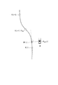
- Fourth operation unit 168 determines the current time based on vehicle position P act (i) recognized by vehicle position recognition unit 140 and speed v and acceleration ⁇ of vehicle M detected by vehicle sensor 60.
- a predicted position P pre (i + 1) at which the vehicle M is expected to arrive at time t i + 1 after one second from t i is derived (step S102).
- the fourth operation unit 168 derives the predicted position P pre (i + 1) based on the following formula (1).
- t is the time of the difference between time t i and time t i + 1 . That is, t in the equation corresponds to the time interval (sampling time) of the orbital point K.
- the subtractor 169 derives a deviation obtained by subtracting the vehicle position P act (i) from the trajectory point K (i) extracted by the second calculation unit 166 (hereinafter, referred to as a present deviation) (step S104). Then, the subtractor 169 outputs the derived current deviation to the proportional integral control unit 171.
- the current deviation is an example of the “first deviation”.
- the subtractor 170 is a deviation obtained by subtracting the predicted position P pre (i + 1) derived by the fourth operation unit 168 from the orbital point K (i + 1) extracted by the third operation unit 167 (hereinafter referred to as a future deviation). Are derived (step S106). Then, the subtractor 170 outputs the derived future deviation to the proportional control unit 172.
- the future deviation is an example of the “second deviation”.
- the proportional-plus-integral control unit 171 multiplies the current deviation output from the subtractor 169 by a predetermined proportional gain and multiplies the time integration value of the current deviation by a predetermined integral gain. Then, the proportional-plus-integral control unit 171 adds the current deviation multiplied by the proportional gain and the time integral value of the present deviation multiplied by the integral gain to track the vehicle M from the vehicle position P act (i)
- a correction amount of speed hereinafter, referred to as a first correction amount
- the vehicle position P act of the current time t i the (i) can be brought closer to the track point K (i) is a target position corresponding to the current time t i.
- the proportional control unit 172 multiplies the future deviation output by the subtractor 170 by a predetermined proportional gain, and shifts the vehicle M from the predicted position P pre (i + 1) to the trajectory point K (i + 1) one second later.
- a correction amount of speed (hereinafter, referred to as a second correction amount) that is close to the speed is derived as an operation amount (step S110).
- the proportional control unit 172 performs proportional control that allows for future deviations including uncertain factors.
- the first output adjustment unit 173 is, for example, a filter circuit that limits the first correction amount derived by the proportional integral control unit 171. For example, the first output adjustment unit 173 performs filtering on the first correction amount so that the speed indicated by the first correction amount does not increase or decrease by 15 km / h or more (step S112).
- the second output adjustment unit 174 is, for example, a filter circuit that limits the second correction amount derived by the proportional control unit 172. For example, like the first output adjustment unit 173, the second output adjustment unit 174 performs filtering on the second correction amount so that the speed indicated by the second correction amount does not increase or decrease by 15 km / h or more (step S114) .
- the speed increase may be different from the speed limit.
- the adder 176 adds the first correction amount adjusted by the first output adjustment unit 173 and the second correction amount adjusted by the second output adjustment unit 174, and adds these correction amounts to a third correction. The amount is output to the third output adjustment unit 175.
- the third output adjustment unit 175 is, for example, a filter circuit that limits the third correction amount output from the adder 176. For example, the third output adjustment unit 175 performs filtering on the third correction amount so that the speed indicated by the third correction amount does not increase or decrease by 5 km / h or more (step S116).
- the adder 177 adds the third correction amount adjusted by the third output adjustment unit 175 to the average velocity derived by the first calculation unit 165, and adds the third correction amount to the average velocity derived from the first time unit i .
- the target velocity is output (step S118). Thereby, the acceleration / deceleration control unit 164 determines the control amount of the driving force output device 200 and the braking device 220 according to the target speed.
- Such control can suppress frequent occurrence of acceleration and deceleration.
- the host vehicle position P act (i) recognized by the host vehicle position recognition unit 140 and the time when the position recognition of the host vehicle M is performed among a plurality of track points K (recognition time, for example, current time t i )
- the host vehicle M is moved from the predicted position Ppre (i + 1) to the track point K ( The target velocity is corrected only by the velocity correction amount which approaches i + 1).
- the offset with respect to the trajectory point K can be reduced. More specifically, since the proportional integral controller 171 derives the first correction amount by performing a time integration of the current deviation, the vehicle position P act of the current time t i the (i), the current time t i Can be closer to the trajectory point K (i) which is the target position corresponding to. Further, by performing proportional control by the proportional control unit 172, it is possible to allow to some extent future deviation including an uncertain element. As a result, frequent occurrence of acceleration and deceleration can be suppressed.
- a predetermined time for example, one second
- the second embodiment will be described below.
- the second embodiment is different from the first embodiment in that the dead zone DZ is set for either or both of the future deviation and the present deviation in order to suppress frequent acceleration and deceleration. Do.
- the dead zone DZ is an area provided to reduce the correction amount corresponding to each deviation. The following description will focus on the differences.
- FIG. 14 is a diagram showing an example of the configuration of the acceleration / deceleration control unit 164A in the second embodiment.
- the acceleration / deceleration control unit 164A further includes a proportional integral gain adjustment unit 180 and a proportional gain adjustment unit 181.
- the proportional integral gain adjustment unit 180 sets the first dead zone DZ1 for the current deviation, and if the current deviation derived by the subtractor 169 is within the first dead zone DZ1, the current deviation is the first dead zone DZ1.
- One or both of the proportional gain and the integral gain in the proportional-plus-integral control unit 171 are reduced as compared to the case where it is not inside.
- the “gain reduction” means bringing a positive value gain close to zero or a negative value, or bringing a negative value gain close to a zero or positive value.
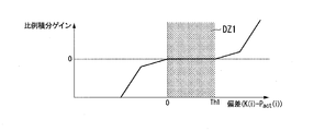
- FIGS. 15 and 16 are diagrams showing an example of the first dead zone DZ1 with respect to the current deviation.
- the first dead zone DZ1 only the positive side of the current deviation (lateral vehicle position P act (i) in comparison with the track point K (i) is a forward) Or may be set to be biased to the positive side.
- the “biased to the positive side” means that, for example, the center of gravity or the like of the area of the first dead zone DZ1 is present on the positive side of the current deviation.
- a region where the deviation is currently from zero to the threshold value Th1 (positive value) is set as the first dead zone DZ1. Further, in the example of FIG.
- a region from the threshold value Th2 (negative value) to the threshold value Th1 (positive value) is set as the first dead zone DZ1.
- the proportional gain and the integral gain are zero. Therefore, if the current deviation is within the first dead zone DZ1, the first correction amount derived by the proportional integral control unit 171 becomes zero or approximately zero.
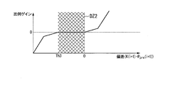
- the proportional gain adjustment unit 181 sets the second dead zone DZ2 for the future deviation, and if the future deviation derived by the subtractor 170 is within the second dead zone DZ2, the future deviation falls within the second dead zone DZ2.
- the proportional gain in the proportional control unit 172 is reduced compared to the case where
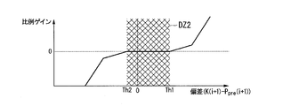
- FIGS. 17 and 18 are diagrams showing an example of the second dead zone DZ2 for the future deviation.
- the second dead zone DZ2 may be set to be only on the positive side or the positive side of the current deviation as in the case of the first dead zone DZ1.
- a region from the current deviation of zero to a threshold value Th1 (positive value) is set as the second dead zone DZ2.
- the region from the threshold value Th2 (negative value) to the threshold value Th1 (positive value) is set as the second dead zone DZ2.
- the proportional gain is zero.
- the second correction amount derived by the proportional control unit 172 becomes zero or almost zero.
- the sizes of the first dead zone DZ1 and the second dead zone DZ2 may be different from each other, or either one is set only on the positive side of the deviation, and the other is set on the positive side. It may be set biased.
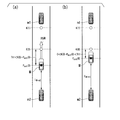
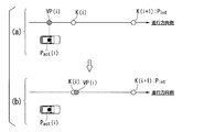
- FIG. 19 is a diagram showing an example of acceleration / deceleration control for each scene.
- FIG. 19A shows one scene in which the current deviation is not within the first dead zone DZ1.
- FIG. 19B shows one scene in which the current deviation is within the first dead zone DZ1.
- the trajectory point K (0) is located forward relative to the vehicle position P act (0) at the current time t 0 . That is, the trajectory point K (0) to be reached by the vehicle M at the present time t 0 has not been reached. Therefore, the acceleration / deceleration control unit 164 needs to control the driving force output device 200 to accelerate the host vehicle M.
- the first correction amount is added to the average speed, and the host vehicle M accelerates from the current average speed.
- the first correction amount decreases.
- the average speed derived by the first calculation unit 165 can be easily maintained without performing the acceleration control. Such processing can suppress frequent acceleration when the host vehicle M has not reached the track point K (0).
- the dead zone DZ is set as the deviation when the trajectory point K (i) is ahead of the own vehicle position P act (i), but the present invention is not limited to this.
- the dead zone DZ may be set as the deviation when the trajectory point K (i) is behind with respect to the position P act (i).
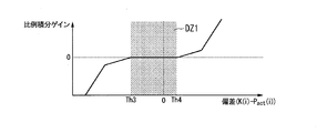
- FIGS. 20 and 21 are diagrams showing other examples of the first dead zone DZ1 with respect to the current deviation.
- the first dead zone DZ1 is only at the negative side of the current deviation (the side where the trajectory point K (i) is behind with respect to the vehicle position P act (i)) Or may be set to be biased to the negative side.
- a region where the current deviation is from the threshold value Th3 (negative value) to zero is set as the first dead zone DZ1.
- a region from the threshold value Th3 (negative value) to the threshold value Th4 (positive value) is set as the first dead zone DZ1.
- the second dead zone DZ2 may be set to be only the negative side of the current deviation or to be biased to the negative side.
- a region where the current deviation is from the threshold value Th3 (negative value) to zero is set as the second dead zone DZ2.
- the region from the threshold value Th3 (negative value) to the threshold value Th4 (positive value) is set as the second dead zone DZ2.
- the sizes of the first dead zone DZ1 and the second dead zone DZ2 may be different from each other, either one is set only on the negative side of the deviation, and the other is negative. It may be set biased to the side.
- FIG. 24 is a diagram showing an example of acceleration / deceleration control for each scene.
- FIG. 24A shows one scene in which the current deviation is not within the first dead zone DZ1.
- FIG. 24 (b) shows a scene in which the current deviation is within the first dead zone DZ1.
- the trajectory point K (0) is located behind the current vehicle position P act (0) at time t 0 . That is, the vehicle M is greater than the track point K (0) to be reached at the current time t 0. Therefore, the acceleration / deceleration control unit 164 needs to control the driving force output device 200 to decelerate the host vehicle M.
- the first correction amount is added to the average speed, and the host vehicle M decelerates from the current average speed.
- the first correction amount decreases.
- the average speed derived by the first calculation unit 165 can be easily maintained without performing the deceleration control. Such processing can suppress frequent deceleration when the host vehicle M exceeds the track point K (0).
- the proportional integral gain adjustment unit 180 described above includes a front vehicle traveling immediately in front of the host vehicle M and a follow on vehicle traveling immediately behind the host vehicle M.
- the area size of the first dead zone DZ1 to be currently set for the deviation may be changed based on the inter-vehicle distance between one or both and the host vehicle M.
- proportional gain adjustment section 181 may deviate in the future based on an inter-vehicle distance between host vehicle M and one or both of a preceding vehicle traveling immediately before host vehicle M and a following vehicle traveling immediately after host vehicle M.
- the area size of the second dead zone DZ2 to be set may be changed.
- FIG. 25 and FIG. 26 are diagrams for explaining the method of changing the area size of the dead zone DZ.
- the proportional integral gain adjustment unit 180 or the proportional gain adjustment unit 181 sets the dead zone which is set when the trajectory point K (i) is ahead of the own vehicle position P act (i).
- the threshold value Th1 on the positive side of DZ is increased on the positive side as the inter-vehicle distance to the following vehicle increases, and is decreased on the positive side as the inter-vehicle distance to the following vehicle decreases. Accordingly, when the inter-vehicle distance to the following vehicle is clogged, the acceleration / deceleration control unit 164 can perform acceleration frequently by narrowing the dead zone DZ in consideration of safety.
- the acceleration / deceleration control unit 164 can reduce the frequency of acceleration by widening the dead zone DZ when the inter-vehicle distance to the following vehicle is increased.
- the proportional integral gain adjustment unit 180 or the proportional gain adjustment unit 181 sets the trajectory point K (i) when the trajectory point K (i) is behind with respect to the vehicle position P act (i).
- the negative threshold value Th3 of the dead zone DZ is increased on the negative side as the inter-vehicle distance to the front vehicle increases, and is decreased on the negative side as the inter-vehicle distance to the front vehicle decreases. . Accordingly, when the inter-vehicle distance to the leading vehicle is clogged, the acceleration / deceleration control unit 164 can frequently perform deceleration by narrowing the dead zone DZ in consideration of safety.
- the acceleration / deceleration control unit 164 can reduce the frequency of deceleration by widening the dead zone DZ when the inter-vehicle distance to the leading vehicle is increased.
- FIG. 27 is a flow chart showing an example of the processing flow of the acceleration / deceleration control unit 164A in the second embodiment.
- the first operation unit 165 determines a trajectory point K that the vehicle M should reach from the plurality of trajectory points K included in the trajectory until the time corresponding to n seconds has elapsed from the current time t i. i) extract K (i + n) from i) and divide the path length of the orbit including K (i) from K (i) by time for n seconds to derive an average velocity (step S200 ).
- the fourth calculation unit 168 calculates A predicted position P pre (i + 1) at which the vehicle M is predicted to arrive at time t i + 1 after one second from the current time t i is derived (step S202).
- the subtractor 169 derives the current deviation obtained by subtracting the vehicle position P act (i) from the trajectory point K (i) extracted by the second operation unit 166 (step S204).
- the subtractor 170 derives a future deviation obtained by subtracting the predicted position P pre (i + 1) derived by the fourth operation unit 168 from the trajectory point K (i + 1) extracted by the third operation unit 167 (see FIG. Step S206).
- the proportional integral gain adjustment unit 180 determines whether the current deviation is within the first dead zone DZ1 (step S208). If the current deviation is within the first dead zone DZ1, the proportional integral control unit One or both of the proportional gain and the integral gain at 171 are decreased (step S210). On the other hand, if the current deviation is not within the first dead zone DZ1, the proportional integral gain adjustment unit 180 shifts the process to S212.
- the proportional-plus-integral control unit 171 multiplies the current deviation output from the subtractor 169 by a predetermined proportional gain, multiplies the time integration value of the current deviation by a predetermined integral gain, and adds these.
- the first correction amount is derived (step S212).
- the first output adjustment unit 173 performs filtering on the first correction amount (step S214).
- the proportional gain adjustment unit 181 determines whether or not the deviation is in the second dead zone DZ2 in the future (step S216), and if the deviation is in the second dead zone DZ2, the proportional control unit 172 The proportional gain is reduced (step S218). On the other hand, when the deviation is not within the second dead zone DZ2, the proportional gain adjustment unit 181 shifts the processing to S220.
- the proportional control unit 172 derives a second correction amount by multiplying the future deviation output from the subtractor 170 by a predetermined proportional gain (step S220).
- the second output adjustment unit 174 performs filtering on the second correction amount (step S222).
- the third output adjustment unit 175 performs filtering on the third correction amount obtained by adding the first correction amount and the second correction amount (step S224).
- the adder 177 adds the third correction amount adjusted by the third output adjustment unit 175 to the average velocity derived by the first calculation unit 165 to add itself to n seconds from the current time t i.
- the target velocity of the vehicle M is output (step S226).
- the dead zone DZ is set for any one or both of the future deviation and the present deviation, the occurrence of frequent acceleration and deceleration can be suppressed. As a result, the passenger's discomfort can be reduced while considering the safety of the vehicle.
- the region of the dead zone DZ is changed based on the inter-vehicle distance to the leading vehicle or the following vehicle, the occurrence of frequent acceleration and deceleration can be efficiently suppressed.
- the third embodiment will be described below.
- the third embodiment differs from the first and third embodiments in that the output gain of the third correction amount is adjusted when the speed of the host vehicle M is low.
- the following description will focus on the differences.
- FIG. 28 is a diagram showing an example of the configuration of the acceleration / deceleration control unit 164B in the third embodiment.
- the acceleration / deceleration control unit 164B includes, for example, a first operation unit 165, a second operation unit 166, a third operation unit 167, a fourth operation unit 168, subtractors 169 and 170, and a proportional integration control unit 171.
- the third gain adjustment unit 183 decreases the output gain for adjusting the third correction amount obtained by adding the first correction amount and the second correction amount.
- the multiplier 184 multiplies the output gain adjusted by the third gain adjustment unit 183 by the third correction amount output from the adder 176, and outputs the product to the adder 177.
- FIG. 29 is a view showing an example of the change of the output gain with respect to the speed v of the host vehicle M.
- the output gain decreases to 1 or less according to the decrease of the speed v. For this reason, when the host vehicle M gradually decelerates and stops, the third correction amount decreases, so the occurrence of acceleration and deceleration is further suppressed.
- the third correction amount is reduced according to the decrease in the speed of the host vehicle M, for example, frequent occurrence of acceleration and deceleration when the host vehicle M stops is suppressed. it can. Thereby, a smooth stop can be performed. Further, according to the third embodiment, since the third correction amount is increased as the speed of the host vehicle M increases, the host vehicle M can be smoothly accelerated from the stop state. As a result, the discomfort of the occupant can be reduced.
- a reference position (hereinafter referred to as a calculation reference position) is set on the track in a predetermined case, and acceleration / deceleration control is performed based on the calculation reference position. This is different from the embodiment of FIG. The following description will focus on the differences.
- FIG. 30 is a diagram showing an example of the configuration of the acceleration / deceleration control unit 164C in the fourth embodiment.
- the acceleration / deceleration control unit 164C further includes, for example, a fifth operation unit 185 in addition to the configuration of the acceleration / deceleration control unit 164 in the first embodiment described above.
- the fifth calculation unit 185 includes, for example, a setting necessity determination unit 185A and a calculation reference position setting unit 185B.
- Setting necessity determination unit 185A determines whether or not calculation reference position setting unit 185B described later needs to perform a predetermined process. For example, when the speed v of the host vehicle M is equal to or less than the speed threshold value Vth illustrated in FIG. 29 described above, the setting necessity determination unit 185A performs calculation in anticipation of a large current deviation and future deviation when traveling at low speeds.
- the reference position setting unit 185B performs predetermined processing.
- setting necessity determination section 185A has a distance from the track generated by track generation section 146 or an arbitrary track point K included in the track to vehicle position P act (i) at current time t i When it is separated by a predetermined distance or more, it may be determined that the host vehicle M deviates from the track, and the arithmetic reference position setting unit 185B may perform predetermined processing.
- the calculation reference position setting unit 185B sets the calculation reference position VP (i) on the trajectory generated by the trajectory generation unit 146 based on the vehicle position P act (i) at the current time t i .
- FIG. 31 is a diagram for describing a setting method of the calculation reference position VP (i).
- the calculation reference position setting unit 185B sets, as a provisional target position P int , an orbital point K (i + 1) corresponding to time t i + 1 which is one second elapsed from the current time t i .
- the provisional target position P int is a position temporarily referred to as a target position when returning from the vehicle position P act (i) onto the trajectory.
- the calculation reference position setting unit 185B selects one of a plurality of tangents to a trajectory connecting each trajectory point K up to the provisional target position P int with a smooth curve (for example, a spline curve).
- a tangent line crossing the perpendicular passing through the vehicle position P act (i) at the contact point is derived, and the calculation reference position VP (i) is set at the intersection point (contact point) with the perpendicular on the tangent line.
- the calculation reference position setting unit 185B outputs the set calculation reference position VP (i) to the first calculation unit 165, the second calculation unit 166, and the fourth calculation unit 168.
- the first operation unit 165 treats the output operation reference position VP (i) as an orbital point K (i) corresponding to the current time t i, and calculates from the operation reference position VP (i) to K
- the path length of the trajectory containing (i + n) is divided by the time of n seconds to derive the average velocity.
- the second operation unit 166 handles the output operation reference position VP (i) as the extracted trajectory point K (i).
- the fourth operation unit 168 derives the predicted position P pre (i + 1) based on the operation reference position VP (i). As a result, even when the host vehicle M deviates from the track, the acceleration / deceleration control unit 164C projects the deviated position onto the track, so that the average speed, the current deviation, and the future deviation are It can be derived.
- the calculation reference position setting unit 185B may set the trajectory point K (i + j) corresponding to the time t i + j after j (j> 1) seconds from the current time t i as the provisional target position P int. .
- the calculation reference position setting unit 185B substitutes, for example, the vehicle position P act at the contact point with the track among a plurality of tangents in contact with the track instead of the setting method of the calculation reference position VP (i) described above.
- a tangent line intersecting the perpendicular line passing through (i) may be derived, and the trajectory point K closest to the intersection point (contact point) with the perpendicular line on the tangent line may be set as the calculation reference position VP (i).
- the calculation reference position setting unit 185B selects one of the trajectory point K (i) and the trajectory point K (i + 1). The trajectory point K (i) closer to the intersection is set as the calculation reference position VP (i).
- the calculation reference position setting unit 185B may correct the calculation reference position VP (i) set on the trajectory based on the positional relationship with the trajectory point K (i) corresponding to the current time t i .
- FIG. 32 schematically shows an example of the correction of the calculation reference position VP (i).
- the calculation reference position VP (i) may be changed to the same position as the orbital point K (i) or a position on the front side of the orbital point K (i).
- the average speed and the current deviation become smaller, it is possible to suppress the rapid increase of the target speed and to prevent the rapid acceleration of the host vehicle M.
- the calculation reference position setting unit 185B corrects the calculation reference position VP (i) set on the orbit based on the positional relationship with the provisional target position P int (for example, the next time point K (i + 1)).
- FIG. 33 schematically shows another example of the correction of the calculation reference position VP (i).
- a limit position LIM to which the calculation reference position VP (i) can be set is set in the trajectory based on the provisional target position P int .
- the calculation reference position setting unit 185B sets the calculation reference position VP (i) at the limit position, as shown in FIG. It may be changed to the same position as LIM or to a position on the front side of the limit position LIM.
- FIG. 34 is a flow chart showing an example of the flow of processing of the fifth arithmetic unit 185 in the fourth embodiment.
- setting necessity determination section 185A determines whether or not own vehicle M deviates from the track (step S300). If the host vehicle M does not deviate from the track, the setting necessity determination unit 185A determines whether the speed v of the host vehicle M is less than or equal to the speed threshold Vth (step S302). If the speed v of the host vehicle M is not equal to or less than the speed threshold Vth, the acceleration / deceleration control unit 164C ends the processing of this flowchart. Note that one of the process of S300 and the process of S302 may be omitted.
- the calculation reference position setting unit 185B determines that the host vehicle position P act at the current time t i Based on i), the calculation reference position VP (i) is set on the trajectory generated by the trajectory generation unit 146 (step S304).
- the calculation reference position setting unit 185B determines whether the set calculation reference position VP (i) is positioned behind the trajectory point K (i) (step S306). When the calculation reference position VP (i) is located behind the trajectory point K (i), the calculation reference position setting unit 185B sets the calculation reference position VP (i) to the same position as the trajectory point K (i), or Correction is made to a position on the front side of the trajectory point K (i) (step S308). On the other hand, if the calculation reference position VP (i) is not located behind the trajectory point K (i), the calculation reference position setting unit 185B ends the processing of this flowchart.
- the first calculation unit 165, the second calculation unit 166, and the fourth calculation unit 168 calculate the calculation reference position VP
- various calculation processes are performed based on i)
- various calculation processes are performed based on the vehicle position P act (i) at the current time t i .
- the first operation unit 165 derives an average velocity by dividing the path length of the trajectory including the trajectory point K (i + n) from the operation reference position VP (i) by the time for n seconds.
- the second operation unit 166 handles the operation reference position VP (i) as the extracted orbital point K (i).
- the subtractor 169 derives a deviation regarding the vehicle traveling direction obtained by subtracting the calculation reference position VP (i) from the track point K (i) corresponding to the current time t i as the present deviation.
- Fourth operation unit 168 calculates current reference position VP (i) and speed v and acceleration ⁇ of host vehicle M detected by vehicle sensor 60 at time t i + 1 at which one second has passed from current time t i .
- a predicted position P pre (i + 1) at which the host vehicle M is predicted to arrive is derived.
- the fifth calculation unit 185 is positioned closest to the position of the vehicle M recognized by the vehicle position recognition unit 140. set the operation reference position VP (i), the first operation unit 165, from among a plurality of track points K included in the track, n seconds worth of time from the current time t i (first predetermined time)
- the trajectory point K (i + n) corresponding to the elapsed time in the future is extracted, and the vehicle M along the trajectory is calculated based on the length of the trajectory from the calculation reference position VP (i) to the trajectory point K (i + n) Deriving the target speed when driving. Therefore, for example, when the vehicle M deviates from the track, or when the speed of the vehicle M becomes equal to or less than the speed threshold Vth and the current deviation or the deviation becomes large, the speed control of the vehicle is accurately performed along the track. be able to.
- the fifth embodiment will be described below.
- the fifth embodiment is different from the first to fourth embodiments in that the target speed to be output is limited without performing the correction process of the calculation reference position VP (i).
- the following description will focus on the differences.
- FIG. 35 is a diagram showing an example of the configuration of the acceleration / deceleration control unit 164D in the fifth embodiment.
- the acceleration / deceleration control unit 164D further includes, for example, a fourth gain adjustment unit 186 and a multiplier 187 in addition to the configuration of the acceleration / deceleration control unit 164 in the fourth embodiment described above.
- the fourth gain adjustment unit 186 calculates the target velocity output from the adder 177 as the velocity v of the host vehicle M decreases, instead of the calculation reference position setting unit 185B correcting the calculation reference position VP (i). Decrease the output gain for adjustment.
- the multiplier 187 multiplies the output gain adjusted by the fourth gain adjustment unit 186 by the target speed output from the adder 177 and outputs the product.
- the calculation reference position VP (i) is set behind the trajectory point K (i), and the distance from the calculation reference position VP (i) to the trajectory point K (i + n) after n seconds is actually When it becomes longer than the distance to drive
- the sixth embodiment will be described below.
- an automatic operation mode is performed in which events in the action plan are changed or executed.
- This embodiment differs from the first to fifth embodiments in that switching to another automatic operation mode or manual operation mode is performed. The following description will focus on the differences.
- the automatic driving mode control unit 130 in the sixth embodiment is a mode of automatic driving that is currently executed when the host vehicle M deviates from the track or when the speed v of the host vehicle M becomes equal to or lower than the speed threshold Vth.
- a mode with a lower degree of automatic operation For example, when mode A without a duty to monitor surroundings is being executed, the automatic operation mode control unit 130 changes the automatic operation mode to be executed to mode B or mode C.
- the vehicle occupant since the vehicle occupant is required to monitor the surroundings, the vehicle occupant can be urged to direct the attention of the vehicle occupant to the periphery of the host vehicle M.
- the vehicle occupant can recognize that the host vehicle M is traveling off the track, and can operate the host vehicle M manually by operating the changeover switch 80 as appropriate.
- the action plan generation unit 144 in the sixth embodiment determines that the vehicle M deviates from the track or the velocity v of the vehicle M becomes equal to or less than the velocity threshold Vth.
- the current event may be changed to an event that does not require (or less) acceleration control.
- the action plan generation unit 144 changes the lane change event to a lane keep event or the like.
- the traveling mode during the lane keeping event is determined as constant speed traveling without acceleration and deceleration. This makes it easy to maintain the automatic operation mode even in a situation where the deviation becomes large.
- the switching control unit 150 in the sixth embodiment performs the case where the host vehicle M deviates from the track or the speed v of the host vehicle M becomes equal to or lower than the speed threshold Vth regardless of the operation of the switch 80. By switching the automatic driving mode to the manual driving mode, the operation right of the host vehicle M can be delegated to the vehicle occupant.
- steering control unit 164 acceleration / deceleration control unit 165: first operation unit 166: second operation unit 167: third operation unit 168: fourth operation unit 169, 170
Abstract
This vehicle control system is provided with: a position recognition unit which recognizes the position of the vehicle; a path generation unit which generates a path in which multiple future target positions to be reached by the vehicle are included in time series; a calculation reference position setting unit which, in the aforementioned path, sets a calculated reference position to the position nearest to the vehicle position recognized by the position recognition unit; and a travel control unit which, from multiple target positions included in the path, extracts a first target position corresponding to the future time when a prescribed time will have elapsed from the time when the vehicle position recognition was carried out, and which, on the basis of the length of the path from the calculation reference position to the first target position, calculates the target speed for the vehicle to travel along the path.
Description
本発明は、車両制御システム、車両制御方法、および車両制御プログラムに関する。
本願は、2016年5月16日に出願された日本国特願2016-098049号に基づき優先権を主張し、その内容をここに援用する。 The present invention relates to a vehicle control system, a vehicle control method, and a vehicle control program.
Priority is claimed on Japanese Patent Application No. 2016-098049, filed May 16, 2016, the content of which is incorporated herein by reference.
従来、前走車の走行軌跡に基づいて、自車両の速度制御や操舵制御を行うシステムが知られている。このシステムは、目標とする車間距離と、前走車両との車間距離との差、および所定時間走行した場合の前走車両と自車両との速度差に基づいて、自車両の速度制御を行うものである(例えば、特許文献1参照)。
BACKGROUND Conventionally, there has been known a system that performs speed control and steering control of a host vehicle based on a traveling trajectory of a leading vehicle. This system controls the speed of the host vehicle based on the difference between the target inter-vehicle distance and the inter-vehicle distance from the host vehicle, and the speed difference between the host vehicle and the host vehicle when traveling for a predetermined time. (See, for example, Patent Document 1).
しかしながら、従来の技術では、走行軌跡を表現した軌道から車両が逸れてしまった場合、適切に速度制御を行うことができない場合があった。
However, in the prior art, when the vehicle deviates from the track representing the traveling locus, there have been cases in which the speed control can not be appropriately performed.
本発明の態様は、軌道に沿って精度良く車両の速度制御を行うことができる車両制御システム、車両制御方法、および車両制御プログラムを提供することを目的の一つとする。
An aspect of the present invention aims to provide a vehicle control system, a vehicle control method, and a vehicle control program capable of performing speed control of a vehicle with high accuracy along a track.
(1)本発明の一態様に係る車両制御システムは、車両の位置を認識する位置認識部と、前記車両が到達すべき将来の目標位置が、時系列に連続して複数含まれる軌道を生成する軌道生成部と、前記軌道において、前記位置認識部により認識された前記車両の位置に最も近い位置に演算基準位置を設定する演算基準位置設定部と、前記軌道に含まれる前記複数の目標位置の中から、前記車両の位置認識がおこなわれた認識時刻から第1の所定時間が経過した将来の時刻に対応する第1の目標位置を抽出し、前記演算基準位置から前記第1の目標位置までの前記軌道の長さに基づいて、前記軌道に沿って前記車両を走行させる際の目標速度を導出する走行制御部と、を備える。
(1) A vehicle control system according to an aspect of the present invention generates a track including a plurality of position recognition units that recognize the position of the vehicle and a plurality of future target positions to be reached by the vehicle, in time series. Track generation unit, a calculation reference position setting unit for setting a calculation reference position at a position closest to the position of the vehicle recognized by the position recognition unit in the track, and the plurality of target positions included in the track From the above, the first target position corresponding to the future time when the first predetermined time has elapsed from the recognition time when the position recognition of the vehicle is performed is extracted, and the first target position is calculated from the calculation reference position And a travel control unit that derives a target speed for causing the vehicle to travel along the track based on the length of the track up to.
(2)上記(1)の態様において、前記演算基準位置設定部が、前記車両の速度が閾値以下である低速走行の場合に、前記演算基準位置を設定してもよい。
(2) In the aspect of (1), the calculation reference position setting unit may set the calculation reference position when traveling at a low speed where the speed of the vehicle is equal to or less than a threshold.
(3)上記(1)または(2)の態様において、前記演算基準位置設定部が、前記車両の位置が前記軌道から所定距離以上離れている場合に、前記演算基準位置を設定してもよい。
(3) In the aspect of the above (1) or (2), the calculation reference position setting unit may set the calculation reference position when the position of the vehicle is separated from the track by a predetermined distance or more. .
(4)上記(1)から(3)のいずれか一項の態様において、前記走行制御部が、前記演算基準位置と、前記車両の位置との第1の偏差に基づいて、前記導出した目標速度を補正してもよい。
(4) In the aspect according to any one of (1) to (3), the travel control unit determines the target derived based on a first deviation between the calculation reference position and the position of the vehicle. The speed may be corrected.
(5)上記(1)から(4)のいずれか一項の態様において、前記走行制御部が、更に、前記認識時刻から、前記第1の所定時間に比して短い第2の所定時間が経過した将来の時刻に対応した第2の目標位置と、前記演算基準位置から走行を開始して前記将来の時刻において前記車両が到達することが予測される予測位置との第2の偏差に基づいて、前記目標速度を補正してもよい。
(5) In the aspect according to any one of (1) to (4), the traveling control unit further determines a second predetermined time shorter than the first predetermined time from the recognition time. Based on a second deviation between a second target position corresponding to an elapsed time in the future and a predicted position at which the vehicle is predicted to arrive at the future time by starting to travel from the calculation reference position. The target speed may be corrected.
(6)上記(1)から(5)のいずれか一項の態様において、少なくとも前記車両の速度制御を自動的に行う自動運転モードと、前記車両の速度制御および操舵制御の双方を前記車両の乗員の操作に基づき行う手動運転モードとを含む複数の運転モードのうちいずれかを実行する自動運転制御部を更に備え、前記走行制御部が、前記自動運転制御部により前記自動運転モードが実行される場合、前記目標速度に応じた前記車両の速度制御を行ってもよい。
(6) In the aspect according to any one of the above (1) to (5), in the automatic driving mode for automatically performing at least speed control of the vehicle, and both speed control and steering control of the vehicle The automatic operation control unit is further provided to execute any one of a plurality of operation modes including a manual operation mode performed based on the operation of the occupant, and the automatic operation mode is executed by the automatic operation control unit. In this case, speed control of the vehicle may be performed according to the target speed.
(7)上記(6)の態様において、前記自動運転モードには、前記車両の周辺監視義務の程度が異なる複数のモードが含まれており、前記自動運転制御部が、前記車両の速度が閾値以下である低速走行の場合、または前記車両の位置が前記軌道から所定距離以上離れている場合に、実行するモードを、より周辺監視義務の程度が低いモードに変更してもよい。
(7) In the aspect of the above (6), the automatic driving mode includes a plurality of modes with different degrees of duty of monitoring the periphery of the vehicle, and the automatic driving control unit determines that the speed of the vehicle is a threshold. In the case of the following low speed traveling, or when the position of the vehicle is separated from the track by a predetermined distance or more, the mode to be executed may be changed to a mode in which the degree of peripheral monitoring duty is lower.
(8)本発明の一態様に係る車両制御方法は、車載コンピュータが、車両の位置を認識し、前記車両が到達すべき将来の目標位置が、時系列に連続して複数含まれる軌道を生成し、前記軌道において、前記認識した前記車両の位置に最も近い位置に演算基準位置を設定し、前記軌道に含まれる前記複数の目標位置の中から、前記車両の位置認識がおこなわれた認識時刻から第1の所定時間が経過した将来の時刻に対応する第1の目標位置を抽出し、前記設定した演算基準位置から前記抽出した目標位置までの前記軌道の長さに基づいて、前記軌道に沿って前記車両を走行させる際の目標速度を導出する。
(8) In the vehicle control method according to one aspect of the present invention, the in-vehicle computer recognizes the position of the vehicle, and generates a track in which a plurality of future target positions to be reached by the vehicle are continuously included in time series And setting a calculation reference position at a position closest to the recognized position of the vehicle on the track, and at a recognition time at which the position of the vehicle is recognized from among the plurality of target positions included in the track A first target position corresponding to a future time when a first predetermined time has elapsed since the first target time, and based on the length of the trajectory from the set calculation reference position to the extracted target position, A target speed when driving the vehicle along is derived.
(9)本発明の一態様に係る車両制御プログラムは、車載コンピュータに、車両の位置を認識させ、前記車両が到達すべき将来の目標位置が、時系列に連続して複数含まれる軌道を生成させ、前記軌道において、前記認識した前記車両の位置に最も近い位置に演算基準位置を設定し、前記軌道に含まれる前記複数の目標位置の中から、前記車両の位置認識がおこなわれた認識時刻から第1の所定時間が経過した将来の時刻に対応する第1の目標位置を抽出させ、前記演算基準位置から前記第1の目標位置までの前記軌道の長さに基づいて、前記軌道に沿って前記車両を走行させる際の目標速度を導出させる、車両制御プログラムである。
(9) The vehicle control program according to an aspect of the present invention causes the on-vehicle computer to recognize the position of the vehicle, and generates a track in which a plurality of future target positions to be reached by the vehicle are continuously included in time series And setting a calculation reference position at a position closest to the recognized position of the vehicle on the track, and a recognition time at which the position of the vehicle is recognized from among the plurality of target positions included in the track And extract a first target position corresponding to a future time when a first predetermined time has elapsed from the point, and along the trajectory based on the length of the trajectory from the calculation reference position to the first target position It is a vehicle control program which derives the target speed at the time of making the vehicle travel.
上記(1)~(9)の態様によれば、軌道に沿って精度良く車両の速度制御を行うことができる。
According to the modes (1) to (9), the speed control of the vehicle can be performed with high accuracy along the track.
以下、図面を参照し、本発明の車両制御システム、車両制御方法、および車両制御プログラムの実施形態について説明する。
Hereinafter, embodiments of a vehicle control system, a vehicle control method, and a vehicle control program according to the present invention will be described with reference to the drawings.
<共通構成>
図1は、各実施形態の車両制御システム100が搭載される車両(以下、自車両Mと称する)の構成要素を示す図である。車両制御システム100が搭載される車両は、例えば、二輪や三輪、四輪等の自動車であり、ディーゼルエンジンやガソリンエンジン等の内燃機関を動力源とした自動車や、電動機を動力源とした電気自動車、内燃機関および電動機を兼ね備えたハイブリッド自動車等を含む。電気自動車は、例えば、二次電池、水素燃料電池、金属燃料電池、アルコール燃料電池等の電池により放電される電力を使用して駆動される。 <Common configuration>
FIG. 1 is a diagram showing components of a vehicle (hereinafter referred to as a host vehicle M) on which thevehicle control system 100 of each embodiment is mounted. The vehicle on which the vehicle control system 100 is mounted is, for example, a two-, three-, or four-wheeled vehicle, such as a vehicle powered by an internal combustion engine such as a diesel engine or gasoline engine, or an electric vehicle powered by a motor. And hybrid vehicles having an internal combustion engine and an electric motor. An electric car is driven using electric power discharged by cells, such as a secondary battery, a hydrogen fuel cell, a metal fuel cell, and an alcohol fuel cell, for example.
図1は、各実施形態の車両制御システム100が搭載される車両(以下、自車両Mと称する)の構成要素を示す図である。車両制御システム100が搭載される車両は、例えば、二輪や三輪、四輪等の自動車であり、ディーゼルエンジンやガソリンエンジン等の内燃機関を動力源とした自動車や、電動機を動力源とした電気自動車、内燃機関および電動機を兼ね備えたハイブリッド自動車等を含む。電気自動車は、例えば、二次電池、水素燃料電池、金属燃料電池、アルコール燃料電池等の電池により放電される電力を使用して駆動される。 <Common configuration>
FIG. 1 is a diagram showing components of a vehicle (hereinafter referred to as a host vehicle M) on which the
図1に示すように、自車両Mには、ファインダ20-1から20-7、レーダ30-1から30-6、およびカメラ40等のセンサと、ナビゲーション装置50(経路誘導装置)と、車両制御システム100とが搭載される。
As shown in FIG. 1, the vehicle M includes sensors such as finders 20-1 to 20-7, radars 30-1 to 30-6, and a camera 40, a navigation device 50 (route guidance device), and a vehicle. A control system 100 is mounted.
ファインダ20-1から20-7は、例えば、照射光に対する散乱光を測定し、対象までの距離を測定するLIDAR(Light Detection and Ranging、或いはLaser Imaging Detection and Ranging)である。例えば、ファインダ20-1は、フロントグリル等に取り付けられ、ファインダ20-2および20-3は、車体の側面やドアミラー、前照灯内部、側方灯付近等に取り付けられる。ファインダ20-4は、トランクリッド等に取り付けられ、ファインダ20-5および20-6は、車体の側面や尾灯内部等に取り付けられる。上述したファインダ20-1から20-6は、例えば、水平方向に関して150度程度の検出領域を有している。また、ファインダ20-7は、ルーフ等に取り付けられる。
ファインダ20-7は、例えば、水平方向に関して360度の検出領域を有している。
レーダ30-1および30-4は、例えば、奥行き方向の検出領域が他のレーダよりも広い長距離ミリ波レーダである。また、レーダ30-2、30-3、30-5、30-6は、レーダ30-1および30-4よりも奥行き方向の検出領域が狭い中距離ミリ波レーダである。 The finders 20-1 to 20-7 are, for example, LIDAR (Light Detection and Ranging, or Laser Imaging Detection and Ranging) which measures the scattered light with respect to the irradiation light and measures the distance to the object. For example, the finder 20-1 is attached to a front grill or the like, and the finders 20-2 and 20-3 are attached to the side of a vehicle body, a door mirror, the inside of a headlight, the vicinity of a side light, or the like. The finder 20-4 is attached to the trunk lid or the like, and the finders 20-5 and 20-6 are attached to the side of the vehicle body, the inside of the taillight, or the like. The finders 20-1 to 20-6 described above have, for example, a detection area of about 150 degrees in the horizontal direction. The finder 20-7 is attached to the roof or the like.
The finder 20-7 has, for example, a detection area of 360 degrees in the horizontal direction.
The radars 30-1 and 30-4 are, for example, long-distance millimeter-wave radars whose detection region in the depth direction is wider than other radars. The radars 30-2, 30-3, 30-5, and 30-6 are middle-range millimeter-wave radars that have a narrower detection area in the depth direction than the radars 30-1 and 30-4.
以下、ファインダ20-1から20-7を特段区別しない場合は、単に「ファインダ20」と記載し、レーダ30-1から30-6を特段区別しない場合は、単に「レーダ30」と記載する。レーダ30は、例えば、FM-CW(Frequency Modulated Continuous Wave)方式によって物体を検出する。
Hereinafter, when the finders 20-1 to 20-7 are not particularly distinguished, they are simply described as "finder 20", and when the radars 30-1 to 30-6 are not distinguished particularly, they are simply described as "radar 30". The radar 30 detects an object by, for example, a frequency modulated continuous wave (FM-CW) method.
カメラ40は、例えば、CCD(Charge Coupled Device)やCMOS(Complementary Metal Oxide Semiconductor)等の固体撮像素子を利用したデジタルカメラである。カメラ40は、フロントウインドシールド上部やルームミラー裏面等に取り付けられる。カメラ40は、例えば、周期的に繰り返し自車両Mの前方を撮像する。カメラ40は、複数のカメラを含むステレオカメラであってもよい。
The camera 40 is a digital camera using a solid-state imaging device such as, for example, a charge coupled device (CCD) or a complementary metal oxide semiconductor (CMOS). The camera 40 is attached to the top of the front windshield, the rear of the rearview mirror, and the like. The camera 40, for example, periodically and repeatedly images the front of the host vehicle M. The camera 40 may be a stereo camera including a plurality of cameras.
なお、図1に示す構成はあくまで一例であり、構成の一部が省略されてもよいし、更に別の構成が追加されてもよい。
The configuration shown in FIG. 1 is merely an example, and a part of the configuration may be omitted, or another configuration may be added.
<第1の実施形態>
図2は、第1の実施形態に係る車両制御システム100を中心とした機能構成図である。
自車両Mには、ファインダ20、レーダ30、およびカメラ40などを含む検知デバイスDDと、ナビゲーション装置50と、通信装置55と、車両センサ60と、表示装置62と、スピーカ64と、コンテンツ再生装置66と、操作デバイス70と、操作検出センサ72と、切替スイッチ80と、車両制御システム100と、駆動力出力装置200と、ステアリング装置210と、ブレーキ装置220とが搭載される。
これらの装置や機器は、CAN(Controller Area Network)通信線等の多重通信線やシリアル通信線、無線通信網等によって互いに接続される。
なお、特許請求の範囲における車両制御システムは、「車両制御システム100」のみを指しているのではなく、車両制御システム100以外の構成(検知デバイスDDなど)を含んでもよい。 First Embodiment
FIG. 2 is a functional configuration diagram centering on thevehicle control system 100 according to the first embodiment.
The vehicle M includes a detection device DD including a finder 20, a radar 30, and acamera 40, a navigation device 50, a communication device 55, a vehicle sensor 60, a display device 62, a speaker 64, and a content reproduction device. An operation device 70, an operation detection sensor 72, a changeover switch 80, a vehicle control system 100, a driving force output device 200, a steering device 210, and a brake device 220 are mounted.
These devices and devices are mutually connected by a multiplex communication line such as a CAN (Controller Area Network) communication line, a serial communication line, a wireless communication network or the like.
Note that the vehicle control system in the claims does not refer to only the "vehicle control system 100", but may include configurations (such as a detection device DD) other than the vehicle control system 100.
図2は、第1の実施形態に係る車両制御システム100を中心とした機能構成図である。
自車両Mには、ファインダ20、レーダ30、およびカメラ40などを含む検知デバイスDDと、ナビゲーション装置50と、通信装置55と、車両センサ60と、表示装置62と、スピーカ64と、コンテンツ再生装置66と、操作デバイス70と、操作検出センサ72と、切替スイッチ80と、車両制御システム100と、駆動力出力装置200と、ステアリング装置210と、ブレーキ装置220とが搭載される。
これらの装置や機器は、CAN(Controller Area Network)通信線等の多重通信線やシリアル通信線、無線通信網等によって互いに接続される。
なお、特許請求の範囲における車両制御システムは、「車両制御システム100」のみを指しているのではなく、車両制御システム100以外の構成(検知デバイスDDなど)を含んでもよい。 First Embodiment
FIG. 2 is a functional configuration diagram centering on the
The vehicle M includes a detection device DD including a finder 20, a radar 30, and a
These devices and devices are mutually connected by a multiplex communication line such as a CAN (Controller Area Network) communication line, a serial communication line, a wireless communication network or the like.
Note that the vehicle control system in the claims does not refer to only the "
ナビゲーション装置50は、GNSS(Global Navigation Satellite System)受信機や地図情報(ナビ地図)、ユーザインターフェースとして機能するタッチパネル式表示装置、スピーカ、マイク等を有する。ナビゲーション装置50は、GNSS受信機によって自車両Mの位置を特定し、その位置からユーザによって指定された目的地までの経路を導出する。
ナビゲーション装置50により導出された経路は、車両制御システム100の目標車線決定部110に提供される。自車両Mの位置は、車両センサ60の出力を利用したINS(Inertial Navigation System)によって特定または補完されてもよい。
また、ナビゲーション装置50は、車両制御システム100が手動運転モードを実行している際に、目的地に至る経路について音声やナビ表示によって案内を行う。
なお、自車両Mの位置を特定するための構成は、ナビゲーション装置50とは独立して設けられてもよい。
また、ナビゲーション装置50は、例えば、ユーザの保有するスマートフォンやタブレット端末等の端末装置の機能によって実現されてもよい。この場合、端末装置と車両制御システム100との間で、無線または有線による通信によって情報の送受信が行われる。 Thenavigation device 50 has a GNSS (Global Navigation Satellite System) receiver, map information (navigation map), a touch panel display device functioning as a user interface, a speaker, a microphone, and the like. The navigation device 50 specifies the position of the host vehicle M by the GNSS receiver, and derives the route from the position to the destination specified by the user.
The route derived by thenavigation device 50 is provided to the target lane determination unit 110 of the vehicle control system 100. The position of the host vehicle M may be identified or supplemented by an INS (Inertial Navigation System) using the output of the vehicle sensor 60.
In addition, when thevehicle control system 100 is executing the manual operation mode, the navigation device 50 provides guidance by voice or navigation display on the route to the destination.
The configuration for specifying the position of the host vehicle M may be provided independently of thenavigation device 50.
In addition, thenavigation device 50 may be realized by, for example, the function of a terminal device such as a smartphone or a tablet terminal owned by the user. In this case, transmission and reception of information are performed between the terminal device and the vehicle control system 100 by wireless or wired communication.
ナビゲーション装置50により導出された経路は、車両制御システム100の目標車線決定部110に提供される。自車両Mの位置は、車両センサ60の出力を利用したINS(Inertial Navigation System)によって特定または補完されてもよい。
また、ナビゲーション装置50は、車両制御システム100が手動運転モードを実行している際に、目的地に至る経路について音声やナビ表示によって案内を行う。
なお、自車両Mの位置を特定するための構成は、ナビゲーション装置50とは独立して設けられてもよい。
また、ナビゲーション装置50は、例えば、ユーザの保有するスマートフォンやタブレット端末等の端末装置の機能によって実現されてもよい。この場合、端末装置と車両制御システム100との間で、無線または有線による通信によって情報の送受信が行われる。 The
The route derived by the
In addition, when the
The configuration for specifying the position of the host vehicle M may be provided independently of the
In addition, the
通信装置55は、例えば、セルラー網やWi-Fi網、Bluetooth(登録商標)、DSRC(Dedicated Short Range Communication)などを利用した無線通信を行う。
The communication device 55 performs wireless communication using, for example, a cellular network, a Wi-Fi network, Bluetooth (registered trademark), DSRC (Dedicated Short Range Communication), or the like.
車両センサ60は、車速を検出する車速センサ、加速度を検出する加速度センサ、鉛直軸回りの角速度を検出するヨーレートセンサ、自車両Mの向きを検出する方位センサ等を含む。車両センサ60は、「検出部」の一例である。
The vehicle sensor 60 includes a vehicle speed sensor that detects a vehicle speed, an acceleration sensor that detects an acceleration, a yaw rate sensor that detects an angular velocity about a vertical axis, an orientation sensor that detects the direction of the host vehicle M, and the like. The vehicle sensor 60 is an example of a “detection unit”.
表示装置62は、例えば、インストルメントパネルの各部、助手席や後部座席に対向する任意の箇所などに取り付けられる、LCD(Liquid Crystal Display)や有機EL(Electroluminescence)表示装置などである。また、表示装置62は、フロントウインドシールドやその他のウインドウに画像を投影するHUD(Head Up Display)であってもよい。また、表示装置62は、タッチパネルである場合にパネルに対するタッチ操作を検出する。スピーカ64は、情報を音声として出力する。
The display device 62 is, for example, an LCD (Liquid Crystal Display), an organic EL (Electroluminescence) display device, or the like which is attached to each part of an instrument panel, an assistant seat, an arbitrary position facing a rear seat, or the like. In addition, the display device 62 may be a HUD (Head Up Display) that projects an image on a front windshield or other windows. In addition, the display device 62 detects a touch operation on the panel when it is a touch panel. The speaker 64 outputs the information as sound.
コンテンツ再生装置66は、例えば、DVD(Digital Versatile Disc)再生装置、CD(Compact Disc)再生装置、テレビジョン受信機、各種案内画像の生成装置などを含む。コンテンツ再生装置66により再生された各種コンテンツ情報は、表示装置62やスピーカ64を介して出力されてよい。
The content reproduction apparatus 66 includes, for example, a DVD (Digital Versatile Disc) reproduction apparatus, a CD (Compact Disc) reproduction apparatus, a television receiver, a generation apparatus of various guidance images, and the like. Various pieces of content information reproduced by the content reproduction device 66 may be output via the display device 62 or the speaker 64.
操作デバイス70は、例えば、アクセルペダルやステアリングホイール、ブレーキペダル、シフトレバー等を含む。操作デバイス70には、運転者による操作の有無や量を検出する操作検出センサ72が取り付けられている。
操作検出センサ72は、例えば、アクセル開度センサ、ステアリングトルクセンサ、ブレーキセンサ、シフト位置センサ等を含む。操作検出センサ72は、検出結果としてのアクセル開度、ステアリングトルク、ブレーキ踏量、シフト位置等を走行制御部160に出力する。
なお、これに代えて、操作検出センサ72の検出結果が、直接的に駆動力出力装置200、ステアリング装置210、またはブレーキ装置220に出力されてもよい。 The operatingdevice 70 includes, for example, an accelerator pedal, a steering wheel, a brake pedal, a shift lever, and the like. An operation detection sensor 72 is attached to the operation device 70 to detect the presence or the amount of the operation by the driver.
Theoperation detection sensor 72 includes, for example, an accelerator opening degree sensor, a steering torque sensor, a brake sensor, a shift position sensor, and the like. The operation detection sensor 72 outputs an accelerator opening degree as a detection result, a steering torque, a brake depression amount, a shift position, and the like to the traveling control unit 160.
Alternatively, the detection result of theoperation detection sensor 72 may be directly output to the driving force output device 200, the steering device 210, or the brake device 220.
操作検出センサ72は、例えば、アクセル開度センサ、ステアリングトルクセンサ、ブレーキセンサ、シフト位置センサ等を含む。操作検出センサ72は、検出結果としてのアクセル開度、ステアリングトルク、ブレーキ踏量、シフト位置等を走行制御部160に出力する。
なお、これに代えて、操作検出センサ72の検出結果が、直接的に駆動力出力装置200、ステアリング装置210、またはブレーキ装置220に出力されてもよい。 The operating
The
Alternatively, the detection result of the
切替スイッチ80は、車両乗員によって操作されるスイッチである。切替スイッチ80は、車両乗員の操作を受け付け、走行制御部160による制御モードを自動運転モードまたは手動運転モードのいずれか一方に指定する制御モード指定信号を生成し、切替制御部150に出力する。
自動運転モードとは、上述したように、運転者が操作を行わない(或いは手動運転モードに比して操作量が小さい、または操作頻度が低い)状態で走行する運転モードである。より具体的には、自動運転モードとは、行動計画に基づいて駆動力出力装置200、ステアリング装置210、およびブレーキ装置220の一部または全部を制御する運転モードである。
また、切替スイッチ80は、自動運転モードを切り替える操作の他に、種々の操作を受け付けてもよい。例えば、車両制御システム100側から出力された情報が表示装置62を介して車両乗員に提示された場合、切替スイッチ80は、これに対する応答操作などを受け付けてよい。 Thechangeover switch 80 is a switch operated by a vehicle occupant. Switch 80 receives the operation of the vehicle occupant, generates a control mode designation signal for designating the control mode of travel control unit 160 as either an automatic driving mode or a manual driving mode, and outputs the control mode designation signal to switching control unit 150.
As described above, the automatic driving mode is a driving mode in which the driver does not operate (or the amount of operation is smaller or the frequency of operation is lower than in the manual operation mode). More specifically, the automatic driving mode is a driving mode in which part or all of the drivingforce output device 200, the steering device 210, and the braking device 220 is controlled based on the action plan.
In addition to the operation of switching the automatic operation mode, thechangeover switch 80 may receive various operations. For example, when the information output from the vehicle control system 100 is presented to the vehicle occupant via the display device 62, the changeover switch 80 may receive a response operation or the like.
自動運転モードとは、上述したように、運転者が操作を行わない(或いは手動運転モードに比して操作量が小さい、または操作頻度が低い)状態で走行する運転モードである。より具体的には、自動運転モードとは、行動計画に基づいて駆動力出力装置200、ステアリング装置210、およびブレーキ装置220の一部または全部を制御する運転モードである。
また、切替スイッチ80は、自動運転モードを切り替える操作の他に、種々の操作を受け付けてもよい。例えば、車両制御システム100側から出力された情報が表示装置62を介して車両乗員に提示された場合、切替スイッチ80は、これに対する応答操作などを受け付けてよい。 The
As described above, the automatic driving mode is a driving mode in which the driver does not operate (or the amount of operation is smaller or the frequency of operation is lower than in the manual operation mode). More specifically, the automatic driving mode is a driving mode in which part or all of the driving
In addition to the operation of switching the automatic operation mode, the
車両制御システム100の説明に先立って、駆動力出力装置200、ステアリング装置210、およびブレーキ装置220について説明する。
Prior to the description of the vehicle control system 100, the driving force output device 200, the steering device 210, and the brake device 220 will be described.
駆動力出力装置200は、車両が走行するための走行駆動力(トルク)を駆動輪に出力する。駆動力出力装置200は、例えば、自車両Mが内燃機関を動力源とした自動車である場合、エンジン、変速機、およびエンジンを制御するエンジンECU(Electronic Control Unit)を備える。また、自車両Mが電動機を動力源とした電気自動車である場合、駆動力出力装置200は、走行用モータおよび走行用モータを制御するモータECUを備える。また、自車両Mがハイブリッド自動車である場合、駆動力出力装置200は、エンジン、変速機、およびエンジンECUと走行用モータおよびモータECUとを備える。
駆動力出力装置200がエンジンのみを含む場合、エンジンECUは、後述する走行制御部160から入力される情報に従って、エンジンのスロットル開度やシフト段等を調整する。
駆動力出力装置200が走行用モータのみを含む場合、モータECUは、走行制御部160から入力される情報に従って、走行用モータに与えるPWM信号のデューティ比を調整する。
駆動力出力装置200がエンジンおよび走行用モータを含む場合、エンジンECUおよびモータECUは、走行制御部160から入力される情報に従って、互いに協調して走行駆動力を制御する。 The drivingforce output device 200 outputs traveling driving force (torque) for the vehicle to travel to the driving wheels. For example, when the host vehicle M is an automobile using an internal combustion engine as a motive power source, the driving force output device 200 includes an engine, a transmission, and an engine ECU (Electronic Control Unit) that controls the engine. In addition, when the host vehicle M is an electric vehicle using an electric motor as a power source, the driving force output device 200 includes a traveling motor and a motor ECU that controls the traveling motor. When the host vehicle M is a hybrid vehicle, the driving force output device 200 includes an engine, a transmission, an engine ECU, a traveling motor, and a motor ECU.
When the drivingforce output device 200 includes only the engine, the engine ECU adjusts the throttle opening degree, shift stage, and the like of the engine according to the information input from the travel control unit 160 described later.
When the drivingforce output device 200 includes only the traveling motor, the motor ECU adjusts the duty ratio of the PWM signal given to the traveling motor in accordance with the information input from the traveling control unit 160.
When the drivingforce output device 200 includes an engine and a traveling motor, the engine ECU and the motor ECU control the traveling driving force in coordination with each other in accordance with the information input from the traveling control unit 160.
駆動力出力装置200がエンジンのみを含む場合、エンジンECUは、後述する走行制御部160から入力される情報に従って、エンジンのスロットル開度やシフト段等を調整する。
駆動力出力装置200が走行用モータのみを含む場合、モータECUは、走行制御部160から入力される情報に従って、走行用モータに与えるPWM信号のデューティ比を調整する。
駆動力出力装置200がエンジンおよび走行用モータを含む場合、エンジンECUおよびモータECUは、走行制御部160から入力される情報に従って、互いに協調して走行駆動力を制御する。 The driving
When the driving
When the driving
When the driving
ステアリング装置210は、例えば、ステアリングECUと、電動モータとを備える。
電動モータは、例えば、ラックアンドピニオン機構に力を作用させて転舵輪の向きを変更する。
ステアリングECUは、車両制御システム100から入力される情報、或いは入力されるステアリング操舵角またはステアリングトルクの情報に従って電動モータを駆動し、転舵輪の向きを変更させる。 Thesteering device 210 includes, for example, a steering ECU and an electric motor.
The electric motor, for example, applies a force to the rack and pinion mechanism to change the direction of the steered wheels.
The steering ECU drives the electric motor according to the information input from thevehicle control system 100 or the information of the steering angle or steering torque input, and changes the direction of the steered wheels.
電動モータは、例えば、ラックアンドピニオン機構に力を作用させて転舵輪の向きを変更する。
ステアリングECUは、車両制御システム100から入力される情報、或いは入力されるステアリング操舵角またはステアリングトルクの情報に従って電動モータを駆動し、転舵輪の向きを変更させる。 The
The electric motor, for example, applies a force to the rack and pinion mechanism to change the direction of the steered wheels.
The steering ECU drives the electric motor according to the information input from the
ブレーキ装置220は、例えば、ブレーキキャリパーと、ブレーキキャリパーに油圧を伝達するシリンダと、シリンダに油圧を発生させる電動モータと、制動制御部とを備える電動サーボブレーキ装置である。
電動サーボブレーキ装置の制動制御部は、走行制御部160から入力される情報に従って電動モータを制御し、制動操作に応じたブレーキトルクが各車輪に出力されるようにする。
電動サーボブレーキ装置は、ブレーキペダルの操作によって発生させた油圧を、マスターシリンダを介してシリンダに伝達する機構をバックアップとして備えてよい。
なお、ブレーキ装置220は、上記説明した電動サーボブレーキ装置に限らず、電子制御式油圧ブレーキ装置であってもよい。電子制御式油圧ブレーキ装置は、走行制御部160から入力される情報に従ってアクチュエータを制御して、マスターシリンダの油圧をシリンダに伝達する。
また、ブレーキ装置220は、駆動力出力装置200に含まれ得る走行用モータによる回生ブレーキを含んでもよい。この回生ブレーキは、駆動力出力装置90に含まれ得る走行用モータにより発電された電力を利用する。 Thebrake device 220 is, for example, an electric servo brake device that includes a brake caliper, a cylinder that transmits hydraulic pressure to the brake caliper, an electric motor that generates hydraulic pressure in the cylinder, and a braking control unit.
The braking control unit of the electric servo brake device controls the electric motor in accordance with the information input from the travelingcontrol unit 160 so that the brake torque corresponding to the braking operation is output to each wheel.
The electric servo brake device may be provided with a mechanism for transmitting the hydraulic pressure generated by the operation of the brake pedal to the cylinder via the master cylinder as a backup.
Thebrake device 220 is not limited to the above-described electric servo brake device, and may be an electronically controlled hydraulic brake device. The electronically controlled hydraulic brake device controls the actuator according to the information input from the travel control unit 160 to transmit the hydraulic pressure of the master cylinder to the cylinder.
In addition, thebraking device 220 may include a regenerative brake by a traveling motor that may be included in the driving force output device 200. The regenerative brake uses the electric power generated by the traveling motor which may be included in the driving force output device 90.
電動サーボブレーキ装置の制動制御部は、走行制御部160から入力される情報に従って電動モータを制御し、制動操作に応じたブレーキトルクが各車輪に出力されるようにする。
電動サーボブレーキ装置は、ブレーキペダルの操作によって発生させた油圧を、マスターシリンダを介してシリンダに伝達する機構をバックアップとして備えてよい。
なお、ブレーキ装置220は、上記説明した電動サーボブレーキ装置に限らず、電子制御式油圧ブレーキ装置であってもよい。電子制御式油圧ブレーキ装置は、走行制御部160から入力される情報に従ってアクチュエータを制御して、マスターシリンダの油圧をシリンダに伝達する。
また、ブレーキ装置220は、駆動力出力装置200に含まれ得る走行用モータによる回生ブレーキを含んでもよい。この回生ブレーキは、駆動力出力装置90に含まれ得る走行用モータにより発電された電力を利用する。 The
The braking control unit of the electric servo brake device controls the electric motor in accordance with the information input from the traveling
The electric servo brake device may be provided with a mechanism for transmitting the hydraulic pressure generated by the operation of the brake pedal to the cylinder via the master cylinder as a backup.
The
In addition, the
[車両制御システム]
以下、車両制御システム100について説明する。車両制御システム100は、例えば、一以上のプロセッサまたは同等の機能を有するハードウェアにより実現される。車両制御システム100は、CPU(Central Processing Unit)などのプロセッサ、記憶装置、および通信インターフェースが内部バスによって接続されたECU(Electronic Control Unit)、或いはMPU(Micro-Processing Unit)などが組み合わされた構成であってよい。 [Vehicle control system]
Hereinafter, thevehicle control system 100 will be described. The vehicle control system 100 is realized by, for example, one or more processors or hardware having equivalent functions. The vehicle control system 100 is configured by combining a processor such as a central processing unit (CPU), a storage device, and an electronic control unit (ECU) having a communication interface connected by an internal bus, or an MPU (micro-processing unit). It may be.
以下、車両制御システム100について説明する。車両制御システム100は、例えば、一以上のプロセッサまたは同等の機能を有するハードウェアにより実現される。車両制御システム100は、CPU(Central Processing Unit)などのプロセッサ、記憶装置、および通信インターフェースが内部バスによって接続されたECU(Electronic Control Unit)、或いはMPU(Micro-Processing Unit)などが組み合わされた構成であってよい。 [Vehicle control system]
Hereinafter, the
図2に戻り、車両制御システム100は、例えば、目標車線決定部110と、自動運転制御部120と、走行制御部160と、記憶部190とを備える。
自動運転制御部120は、例えば、自動運転モード制御部130と、自車位置認識部140と、外界認識部142と、行動計画生成部144と、軌道生成部146と、切替制御部150とを備える。 Returning to FIG. 2, thevehicle control system 100 includes, for example, a target lane determination unit 110, an automatic driving control unit 120, a travel control unit 160, and a storage unit 190.
The automaticdriving control unit 120 includes, for example, an automatic driving mode control unit 130, a host vehicle position recognition unit 140, an external world recognition unit 142, an action plan generation unit 144, a track generation unit 146, and a switching control unit 150. Prepare.
自動運転制御部120は、例えば、自動運転モード制御部130と、自車位置認識部140と、外界認識部142と、行動計画生成部144と、軌道生成部146と、切替制御部150とを備える。 Returning to FIG. 2, the
The automatic
目標車線決定部110、自動運転制御部120の各部、および走行制御部160のうち一部または全部は、プロセッサがプログラム(ソフトウェア)を実行することにより実現される。また、これらのうち一部または全部は、LSI(Large Scale Integration)やASIC(Application Specific Integrated Circuit)等のハードウェアによって実現されてもよいし、ソフトウェアとハードウェアの組み合わせによって実現されてもよい。
The processor executes a program (software) to realize part or all of the target lane determination unit 110, the units of the automatic driving control unit 120, and the travel control unit 160. Also, some or all of these may be realized by hardware such as LSI (Large Scale Integration) or ASIC (Application Specific Integrated Circuit), or may be realized by a combination of software and hardware.
記憶部190には、例えば、高精度地図情報192、目標車線情報194、行動計画情報196、制御モードに対応した操作可否情報198などの情報が格納される。
記憶部190は、ROM(Read Only Memory)やRAM(Random Access Memory)、HDD(Hard Disk Drive)、フラッシュメモリ等で実現される。プロセッサが実行するプログラムは、予め記憶部190に格納されていてもよいし、車載インターネット設備等を介して外部装置からダウンロードされてもよい。
また、プログラムは、そのプログラムを格納した可搬型記憶媒体が図示しないドライブ装置に装着されることで記憶部190にインストールされてもよい。
また、車両制御システム100は、複数のコンピュータ装置によって分散化されたものであってもよい。 Thestorage unit 190 stores, for example, information such as high accuracy map information 192, target lane information 194, action plan information 196, and operation permission information 198 corresponding to the control mode.
Thestorage unit 190 is realized by a read only memory (ROM), a random access memory (RAM), a hard disk drive (HDD), a flash memory, or the like. The program executed by the processor may be stored in advance in the storage unit 190, or may be downloaded from an external device via an in-vehicle Internet facility or the like.
The program may be installed in thestorage unit 190 by mounting a portable storage medium storing the program in a drive device (not shown).
In addition, thevehicle control system 100 may be distributed by a plurality of computer devices.
記憶部190は、ROM(Read Only Memory)やRAM(Random Access Memory)、HDD(Hard Disk Drive)、フラッシュメモリ等で実現される。プロセッサが実行するプログラムは、予め記憶部190に格納されていてもよいし、車載インターネット設備等を介して外部装置からダウンロードされてもよい。
また、プログラムは、そのプログラムを格納した可搬型記憶媒体が図示しないドライブ装置に装着されることで記憶部190にインストールされてもよい。
また、車両制御システム100は、複数のコンピュータ装置によって分散化されたものであってもよい。 The
The
The program may be installed in the
In addition, the
目標車線決定部110は、例えば、MPUにより実現される。目標車線決定部110は、ナビゲーション装置50から提供された経路を複数のブロックに分割し(例えば、車両進行方向に関して100[m]毎に分割し)、高精度地図情報192を参照してブロックごとに目標車線を決定する。目標車線決定部110は、例えば、左から何番目の車線を走行するといった決定を行う。目標車線決定部110は、例えば、経路において分岐箇所や合流箇所などが存在する場合、自車両Mが、分岐先に進行するための合理的な走行経路を走行できるように、目標車線を決定する。目標車線決定部110により決定された目標車線は、目標車線情報194として記憶部190に記憶される。
The target lane determination unit 110 is realized by, for example, an MPU. The target lane determination unit 110 divides the route provided from the navigation device 50 into a plurality of blocks (for example, in units of 100 [m] in the traveling direction of the vehicle), and refers to the high accuracy map information 192 for each block Determine your target lane. The target lane determination unit 110 determines, for example, which lane from the left the vehicle should travel. The target lane determination unit 110 determines the target lane so that the host vehicle M can travel on a rational travel route for advancing to the branch destination, for example, when there is a branch point or a junction point in the route. . The target lane determined by the target lane determination unit 110 is stored in the storage unit 190 as target lane information 194.
高精度地図情報192は、ナビゲーション装置50が有するナビ地図よりも高精度な地図情報である。高精度地図情報192は、例えば、車線の中央の情報あるいは車線の境界の情報等を含んでいる。
また、高精度地図情報192には、道路情報、交通規制情報、住所情報(住所・郵便番号)、施設情報、電話番号情報などが含まれてよい。
道路情報には、高速道路、有料道路、国道、都道府県道といった道路の種別を表す情報や、道路の車線数、各車線の幅員、道路の勾配、道路の位置(経度、緯度、高さを含む3次元座標)、車線のカーブの曲率、車線の合流および分岐ポイントの位置、道路に設けられた標識等の情報が含まれる。
交通規制情報には、工事や交通事故、渋滞等によって車線が封鎖されているといった情報が含まれる。 The highaccuracy map information 192 is map information that is more accurate than the navigation map of the navigation device 50. The high accuracy map information 192 includes, for example, information on the center of the lane or information on the boundary of the lane.
Also, the highaccuracy map information 192 may include road information, traffic regulation information, address information (address / zip code), facility information, telephone number information, and the like.
The road information includes information indicating the type of road such as expressways, toll roads, national roads, and prefectural roads, the number of lanes of the road, the width of each lane, the slope of the road, the position of the road (longitude, latitude, height 3) (including three-dimensional coordinates), curvature of a curve of a lane, locations of merging and branching points of lanes, and information such as signs provided on roads.
The traffic regulation information includes information that the lane is blocked due to construction work, traffic accident, traffic jam or the like.
また、高精度地図情報192には、道路情報、交通規制情報、住所情報(住所・郵便番号)、施設情報、電話番号情報などが含まれてよい。
道路情報には、高速道路、有料道路、国道、都道府県道といった道路の種別を表す情報や、道路の車線数、各車線の幅員、道路の勾配、道路の位置(経度、緯度、高さを含む3次元座標)、車線のカーブの曲率、車線の合流および分岐ポイントの位置、道路に設けられた標識等の情報が含まれる。
交通規制情報には、工事や交通事故、渋滞等によって車線が封鎖されているといった情報が含まれる。 The high
Also, the high
The road information includes information indicating the type of road such as expressways, toll roads, national roads, and prefectural roads, the number of lanes of the road, the width of each lane, the slope of the road, the position of the road (longitude, latitude, height 3) (including three-dimensional coordinates), curvature of a curve of a lane, locations of merging and branching points of lanes, and information such as signs provided on roads.
The traffic regulation information includes information that the lane is blocked due to construction work, traffic accident, traffic jam or the like.
自動運転モード制御部130は、自動運転制御部120が実施する自動運転のモードを決定する。本実施形態における自動運転のモードには、以下のモードが含まれる。なお、以下はあくまで一例であり、自動運転のモードの数や種類は任意に決定されてよい。
[モードA]
モードAは、最も自動運転の度合が高いモードである。モードAが実施されている場合、複雑な合流制御など、全ての車両制御が自動的に行われるため、車両乗員は自車両Mの周辺や状態を監視する必要が無い。すなわち、モードAでは、車両乗員に周辺監視義務が課されない。
[モードB]
モードBは、モードAの次に自動運転の度合が高いモードである。モードBが実施されている場合、原則として全ての車両制御が自動的に行われるが、場面に応じて自車両Mの運転操作が車両乗員に委ねられる。このため、車両乗員は自車両Mの周辺や状態を監視している必要がある。すなわち、モードBでは、車両乗員に周辺監視義務が課される。
[モードC]
モードCは、モードBの次に自動運転の度合が高いモードである。モードCが実施されている場合、車両乗員は、場面に応じた切替スイッチ80に対する確認操作を行う必要がある。モードCでは、例えば、車線変更のタイミングが車両乗員に通知され、車両乗員が切替スイッチ80に対して車線変更を指示する操作を行った場合に、自動的な車線変更が行われる。このため、車両乗員は自車両Mの周辺や状態を監視している必要がある。すなわち、モードCでは、車両乗員に周辺監視義務が課される。 The automatic drivingmode control unit 130 determines the mode of the automatic driving performed by the automatic driving control unit 120. The modes of the automatic driving in this embodiment include the following modes. The following is merely an example, and the number and type of modes of automatic driving may be determined arbitrarily.
[Mode A]
Mode A is the mode in which the degree of automatic operation is the highest. When the mode A is performed, all vehicle control such as complicated merging control is automatically performed, and the vehicle occupant does not have to monitor the periphery or the state of the host vehicle M. That is, in mode A, the vehicle occupant is not required to monitor the surroundings.
[Mode B]
Mode B is a mode in which the degree of automatic operation is the second highest after mode A. When the mode B is performed, all vehicle control is performed automatically in principle, but the driving operation of the host vehicle M is entrusted to the vehicle occupant according to the scene. Therefore, the vehicle occupant needs to monitor the surroundings and the state of the host vehicle M. That is, in mode B, the vehicle occupant is required to monitor the surroundings.
[Mode C]
Mode C is a mode in which the degree of automatic operation is the second highest after mode B. When the mode C is performed, the vehicle occupant needs to perform a confirmation operation on thechangeover switch 80 according to the scene. In mode C, for example, when the lane change timing is notified to the vehicle occupant and the vehicle occupant instructs the changeover switch 80 to perform the lane change operation, the automatic lane change is performed. Therefore, the vehicle occupant needs to monitor the surroundings and the state of the host vehicle M. That is, in mode C, the vehicle occupant is required to monitor the surroundings.
[モードA]
モードAは、最も自動運転の度合が高いモードである。モードAが実施されている場合、複雑な合流制御など、全ての車両制御が自動的に行われるため、車両乗員は自車両Mの周辺や状態を監視する必要が無い。すなわち、モードAでは、車両乗員に周辺監視義務が課されない。
[モードB]
モードBは、モードAの次に自動運転の度合が高いモードである。モードBが実施されている場合、原則として全ての車両制御が自動的に行われるが、場面に応じて自車両Mの運転操作が車両乗員に委ねられる。このため、車両乗員は自車両Mの周辺や状態を監視している必要がある。すなわち、モードBでは、車両乗員に周辺監視義務が課される。
[モードC]
モードCは、モードBの次に自動運転の度合が高いモードである。モードCが実施されている場合、車両乗員は、場面に応じた切替スイッチ80に対する確認操作を行う必要がある。モードCでは、例えば、車線変更のタイミングが車両乗員に通知され、車両乗員が切替スイッチ80に対して車線変更を指示する操作を行った場合に、自動的な車線変更が行われる。このため、車両乗員は自車両Mの周辺や状態を監視している必要がある。すなわち、モードCでは、車両乗員に周辺監視義務が課される。 The automatic driving
[Mode A]
Mode A is the mode in which the degree of automatic operation is the highest. When the mode A is performed, all vehicle control such as complicated merging control is automatically performed, and the vehicle occupant does not have to monitor the periphery or the state of the host vehicle M. That is, in mode A, the vehicle occupant is not required to monitor the surroundings.
[Mode B]
Mode B is a mode in which the degree of automatic operation is the second highest after mode A. When the mode B is performed, all vehicle control is performed automatically in principle, but the driving operation of the host vehicle M is entrusted to the vehicle occupant according to the scene. Therefore, the vehicle occupant needs to monitor the surroundings and the state of the host vehicle M. That is, in mode B, the vehicle occupant is required to monitor the surroundings.
[Mode C]
Mode C is a mode in which the degree of automatic operation is the second highest after mode B. When the mode C is performed, the vehicle occupant needs to perform a confirmation operation on the
自動運転モード制御部130は、切替スイッチ80に対する車両乗員の操作、行動計画生成部144により決定されたイベント、軌道生成部146により決定された走行態様などに基づいて、自動運転のモードを決定する。
自動運転モード制御部130により決定された自動運転のモードに関する情報は、出力制御部155に通知される。自動運転のモードには、自車両Mの検知デバイスDDの性能等に応じた限界が設定されてもよい。例えば、検知デバイスDDの性能が低い場合には、モードAは実施されないものとしてよい。
いずれのモードにおいても、切替スイッチ80に対する操作によって、手動運転モードに切り替えること(オーバーライド)は可能である。 The automatic drivingmode control unit 130 determines the automatic driving mode based on the operation of the vehicle occupant on the changeover switch 80, the event determined by the action plan generating unit 144, the traveling mode determined by the trajectory generating unit 146, and the like. .
Information on the mode of automatic driving determined by the automatic drivingmode control unit 130 is notified to the output control unit 155. A limit corresponding to the performance of the detection device DD of the host vehicle M may be set in the mode of the automatic driving. For example, if the performance of the sensing device DD is low, mode A may not be implemented.
In any mode, it is possible to switch to the manual operation mode (override) by operating thechangeover switch 80.
自動運転モード制御部130により決定された自動運転のモードに関する情報は、出力制御部155に通知される。自動運転のモードには、自車両Mの検知デバイスDDの性能等に応じた限界が設定されてもよい。例えば、検知デバイスDDの性能が低い場合には、モードAは実施されないものとしてよい。
いずれのモードにおいても、切替スイッチ80に対する操作によって、手動運転モードに切り替えること(オーバーライド)は可能である。 The automatic driving
Information on the mode of automatic driving determined by the automatic driving
In any mode, it is possible to switch to the manual operation mode (override) by operating the
自動運転制御部120の自車位置認識部140は、記憶部190に格納された高精度地図情報192と、ファインダ20、レーダ30、カメラ40、ナビゲーション装置50、または車両センサ60から入力される情報とに基づいて、自車両Mが走行している車線(走行車線)、および、走行車線に対する自車両Mの相対位置を認識する。
The vehicle position recognition unit 140 of the automatic driving control unit 120 receives information from the high accuracy map information 192 stored in the storage unit 190, the finder 20, the radar 30, the camera 40, the navigation device 50, or the vehicle sensor 60. And recognizes the relative position of the host vehicle M with respect to the travel lane and the lane in which the host vehicle M is traveling (traveling lane).
自車位置認識部140は、例えば、高精度地図情報192から認識される道路区画線のパターン(例えば実線と破線の配列)と、カメラ40によって撮像された画像から認識される自車両Mの周辺の道路区画線のパターンとを比較することで、走行車線を認識する。
この認識において、ナビゲーション装置50から取得される自車両Mの位置やINSによる処理結果が加味されてもよい。 For example, the vehicleposition recognition unit 140 recognizes the pattern of road division lines (for example, an array of solid lines and broken lines) recognized from the high accuracy map information 192 and the surroundings of the vehicle M recognized from the image captured by the camera 40 The traveling lane is recognized by comparing with the pattern of the road division lines.
In this recognition, the position of the host vehicle M acquired from thenavigation device 50 or the processing result by the INS may be added.
この認識において、ナビゲーション装置50から取得される自車両Mの位置やINSによる処理結果が加味されてもよい。 For example, the vehicle
In this recognition, the position of the host vehicle M acquired from the
図3は、自車位置認識部140により走行車線L1に対する自車両Mの相対位置が認識される様子を示す図である。自車位置認識部140は、例えば、自車両Mの基準点G(例えば重心)の走行車線中央CLからの乖離OS、および自車両Mの進行方向の走行車線中央CLを連ねた線に対してなす角度θを、走行車線L1に対する自車両Mの相対位置として認識する。
なお、これに代えて、自車位置認識部140は、自車線L1のいずれかの側端部に対する自車両Mの基準点の位置などを、走行車線に対する自車両Mの相対位置として認識してもよい。自車位置認識部140により認識される自車両Mの相対位置は、目標車線決定部110に提供される。 FIG. 3 is a diagram showing how the vehicleposition recognition unit 140 recognizes the relative position of the vehicle M with respect to the traveling lane L1. The host vehicle position recognition unit 140, for example, is a line connecting the deviation OS of the reference point G (for example, the center of gravity) of the host vehicle M from the center CL of the traveling lane and the center CL of the traveling lane The angle θ to be formed is recognized as the relative position of the host vehicle M with respect to the traveling lane L1.
Instead of this, the vehicleposition recognition unit 140 recognizes the position of the reference point of the vehicle M relative to any one side end of the vehicle lane L1 as the relative position of the vehicle M relative to the traveling lane. It is also good. The relative position of the host vehicle M recognized by the host vehicle position recognition unit 140 is provided to the target lane determination unit 110.
なお、これに代えて、自車位置認識部140は、自車線L1のいずれかの側端部に対する自車両Mの基準点の位置などを、走行車線に対する自車両Mの相対位置として認識してもよい。自車位置認識部140により認識される自車両Mの相対位置は、目標車線決定部110に提供される。 FIG. 3 is a diagram showing how the vehicle
Instead of this, the vehicle
外界認識部142は、ファインダ20、レーダ30、カメラ40等から入力される情報に基づいて、周辺車両の位置、および速度、加速度等の状態を認識する。
周辺車両とは、例えば、自車両Mの周辺を走行する車両であって、自車両Mと同じ方向に走行する車両である。周辺車両の位置は、他車両の重心やコーナー等の代表点で表されてもよいし、他車両の輪郭で表現された領域で表されてもよい。
周辺車両の「状態」とは、上記各種機器の情報に基づいて把握される、周辺車両の加速度、車線変更をしているか否か(あるいは車線変更をしようとしているか否か)を含んでもよい。
また、外界認識部142は、周辺車両に加えて、ガードレールや電柱、駐車車両、歩行者その他の物体の位置を認識してもよい。 The externalworld recognition unit 142 recognizes the position of the surrounding vehicle and the state of the speed, acceleration, and the like based on the information input from the finder 20, the radar 30, the camera 40, and the like.
The surrounding vehicle is, for example, a vehicle traveling around the host vehicle M and traveling in the same direction as the host vehicle M. The position of the surrounding vehicle may be represented by a representative point such as the center of gravity or a corner of the other vehicle, or may be represented by an area represented by the contour of the other vehicle.
The "state" of the surrounding vehicle may include the acceleration of the surrounding vehicle, whether it is changing lanes (or whether it is going to change lanes), which is grasped based on the information of the various devices.
In addition to the surrounding vehicles, the outsideworld recognition unit 142 may also recognize positions of guardrails, utility poles, parked vehicles, pedestrians, and other objects.
周辺車両とは、例えば、自車両Mの周辺を走行する車両であって、自車両Mと同じ方向に走行する車両である。周辺車両の位置は、他車両の重心やコーナー等の代表点で表されてもよいし、他車両の輪郭で表現された領域で表されてもよい。
周辺車両の「状態」とは、上記各種機器の情報に基づいて把握される、周辺車両の加速度、車線変更をしているか否か(あるいは車線変更をしようとしているか否か)を含んでもよい。
また、外界認識部142は、周辺車両に加えて、ガードレールや電柱、駐車車両、歩行者その他の物体の位置を認識してもよい。 The external
The surrounding vehicle is, for example, a vehicle traveling around the host vehicle M and traveling in the same direction as the host vehicle M. The position of the surrounding vehicle may be represented by a representative point such as the center of gravity or a corner of the other vehicle, or may be represented by an area represented by the contour of the other vehicle.
The "state" of the surrounding vehicle may include the acceleration of the surrounding vehicle, whether it is changing lanes (or whether it is going to change lanes), which is grasped based on the information of the various devices.
In addition to the surrounding vehicles, the outside
行動計画生成部144は、自動運転のスタート地点、および/または自動運転の目的地を設定する。自動運転のスタート地点は、自車両Mの現在位置であってもよいし、自動運転を指示する操作がなされた地点でもよい。行動計画生成部144は、そのスタート地点と自動運転の目的地との間の区間において、行動計画を生成する。なお、これに限らず、行動計画生成部144は、任意の区間について行動計画を生成してもよい。
The action plan generation unit 144 sets a start point of the autonomous driving and / or a destination of the autonomous driving. The starting point of the autonomous driving may be the current position of the host vehicle M or a point at which the operation for instructing the autonomous driving is performed. The action plan generation unit 144 generates an action plan in the section between the start point and the destination of the automatic driving. Not limited to this, the action plan generation unit 144 may generate an action plan for any section.
行動計画は、例えば、順次実行される複数のイベントで構成される。イベントには、例えば、自車両Mを減速させる減速イベントや、自車両Mを加速させる加速イベント、走行車線を逸脱しないように自車両Mを走行させるレーンキープイベント、走行車線を変更させる車線変更イベント、自車両Mに前走車両を追い越させる追い越しイベント、分岐ポイントにおいて所望の車線に変更させたり、現在の走行車線を逸脱しないように自車両Mを走行させたりする分岐イベント、本線に合流するための合流車線において自車両Mを加減速させ、走行車線を変更させる合流イベント、自動運転の開始地点で手動運転モードから自動運転モードに移行させたり、自動運転の終了予定地点で自動運転モードから手動運転モードに移行させたりするハンドオーバイベント等が含まれる。
行動計画生成部144は、目標車線決定部110により決定された目標車線が切り替わる箇所において、車線変更イベント、分岐イベント、または合流イベントを設定する。
行動計画生成部144によって生成された行動計画を示す情報は、行動計画情報196として記憶部190に格納される。 The action plan is composed of, for example, a plurality of events that are sequentially executed. Events include, for example, a deceleration event for decelerating the host vehicle M, an acceleration event for accelerating the host vehicle M, a lane keep event for traveling the host vehicle M not to deviate from the lane, and a lane change event for changing the lane In order to join the main line, an overtaking event that causes the host vehicle M to overtake the preceding vehicle, a branch event that changes the lane to a desired lane at a branch point, or causes the host vehicle M to travel so as not to deviate from the current traveling lane. In the confluence lane, accelerate or decelerate the host vehicle M and change the traffic lane, transition from the manual operation mode to the automatic operation mode at the start point of automatic driving, or manually from the automatic operation mode at the scheduled end point of automatic operation A handover event or the like for shifting to the operation mode is included.
The actionplan generation unit 144 sets a lane change event, a branch event, or a merging event at a point where the target lane determined by the target lane determination unit 110 is switched.
Information indicating the action plan generated by the actionplan generation unit 144 is stored in the storage unit 190 as the action plan information 196.
行動計画生成部144は、目標車線決定部110により決定された目標車線が切り替わる箇所において、車線変更イベント、分岐イベント、または合流イベントを設定する。
行動計画生成部144によって生成された行動計画を示す情報は、行動計画情報196として記憶部190に格納される。 The action plan is composed of, for example, a plurality of events that are sequentially executed. Events include, for example, a deceleration event for decelerating the host vehicle M, an acceleration event for accelerating the host vehicle M, a lane keep event for traveling the host vehicle M not to deviate from the lane, and a lane change event for changing the lane In order to join the main line, an overtaking event that causes the host vehicle M to overtake the preceding vehicle, a branch event that changes the lane to a desired lane at a branch point, or causes the host vehicle M to travel so as not to deviate from the current traveling lane. In the confluence lane, accelerate or decelerate the host vehicle M and change the traffic lane, transition from the manual operation mode to the automatic operation mode at the start point of automatic driving, or manually from the automatic operation mode at the scheduled end point of automatic operation A handover event or the like for shifting to the operation mode is included.
The action
Information indicating the action plan generated by the action
図4は、ある区間について生成された行動計画の一例を示す図である。図4に示すように、行動計画生成部144は、目標車線情報194が示す目標車線上を自車両Mが走行するために必要な行動計画を生成する。なお、行動計画生成部144は、自車両Mの状況変化に応じて、目標車線情報194に拘わらず、動的に行動計画を変更してもよい。
例えば、行動計画生成部144は、車両走行中に外界認識部142によって認識された周辺車両の速度が閾値を超えたり、自車線に隣接する車線を走行する周辺車両の移動方向が自車線方向に向いたりした場合に、自車両Mが走行予定の運転区間に設定されたイベントを変更する。
例えば、レーンキープイベントの後に車線変更イベントが実行されるようにイベントが設定されている場合において、外界認識部142の認識結果によって当該レーンキープイベント中に車線変更先の車線後方から車両が閾値以上の速度で進行してきたことが判明した場合、行動計画生成部144は、レーンキープイベントの次のイベントを、車線変更イベントから減速イベントやレーンキープイベント等に変更してよい。この結果、車両制御システム100は、外界の状態に変化が生じた場合においても、安全に自車両Mを自動走行させることができる。 FIG. 4 is a diagram showing an example of an action plan generated for a certain section. As shown in FIG. 4, the actionplan generation unit 144 generates an action plan necessary for the host vehicle M to travel on the target lane indicated by the target lane information 194. The action plan generation unit 144 may dynamically change the action plan according to the change in the situation of the host vehicle M, regardless of the target lane information 194.
For example, in the actionplan generation unit 144, the speed of the surrounding vehicle recognized by the external world recognition unit 142 exceeds the threshold while the vehicle is traveling, or the moving direction of the surrounding vehicle traveling in the lane adjacent to the own lane In the case of turning, the event set in the driving section where the host vehicle M is to travel is changed.
For example, when an event is set such that a lane change event is executed after a lane keep event, the recognition result of the externalworld recognition unit 142 causes the vehicle to exceed the threshold from behind the lane in the lane change destination during the lane keep event. If it is determined that the vehicle has progressed at the speed of 1, the action plan generation unit 144 may change the event following the lane keeping event from a lane change event to a deceleration event, a lane keeping event, or the like. As a result, the vehicle control system 100 can safely cause the host vehicle M to travel automatically even when a change occurs in the state of the outside world.
例えば、行動計画生成部144は、車両走行中に外界認識部142によって認識された周辺車両の速度が閾値を超えたり、自車線に隣接する車線を走行する周辺車両の移動方向が自車線方向に向いたりした場合に、自車両Mが走行予定の運転区間に設定されたイベントを変更する。
例えば、レーンキープイベントの後に車線変更イベントが実行されるようにイベントが設定されている場合において、外界認識部142の認識結果によって当該レーンキープイベント中に車線変更先の車線後方から車両が閾値以上の速度で進行してきたことが判明した場合、行動計画生成部144は、レーンキープイベントの次のイベントを、車線変更イベントから減速イベントやレーンキープイベント等に変更してよい。この結果、車両制御システム100は、外界の状態に変化が生じた場合においても、安全に自車両Mを自動走行させることができる。 FIG. 4 is a diagram showing an example of an action plan generated for a certain section. As shown in FIG. 4, the action
For example, in the action
For example, when an event is set such that a lane change event is executed after a lane keep event, the recognition result of the external
図5は、軌道生成部146の構成の一例を示す図である。軌道生成部146は、例えば、走行態様決定部146Aと、軌道候補生成部146Bと、評価・選択部146Cとを備える。
FIG. 5 is a diagram showing an example of the configuration of the trajectory generation unit 146. As shown in FIG. The track generation unit 146 includes, for example, a traveling mode determination unit 146A, a track candidate generation unit 146B, and an evaluation / selection unit 146C.
走行態様決定部146Aは、例えば、レーンキープイベントを実施する際に、定速走行、追従走行、低速追従走行、減速走行、カーブ走行、障害物回避走行などのうちいずれかの走行態様を決定する。
この場合、走行態様決定部146Aは、自車両Mの前方に他車両が存在しない場合に、走行態様を定速走行に決定する。
また、走行態様決定部146Aは、前走車両に対して追従走行するような場合に、走行態様を追従走行に決定する。
また、走行態様決定部146Aは、渋滞場面などにおいて、走行態様を低速追従走行に決定する。
また、走行態様決定部146Aは、外界認識部142により前走車両の減速が認識された場合や、停車や駐車などのイベントを実施する場合に、走行態様を減速走行に決定する。
また、走行態様決定部146Aは、外界認識部142により自車両Mがカーブ路に差し掛かったことが認識された場合に、走行態様をカーブ走行に決定する。
また、走行態様決定部146Aは、外界認識部142により自車両Mの前方に障害物が認識された場合に、走行態様を障害物回避走行に決定する。
また、走行態様決定部146Aは、車線変更イベント、追い越しイベント、分岐イベント、合流イベント、ハンドオーバイベントなどを実施する場合に、それぞれのイベントに応じた走行態様を決定する。 For example, when performing the lane keeping event, the travelingmode determination unit 146A determines one of the traveling modes among constant speed traveling, following traveling, low speed following traveling, deceleration traveling, curve traveling, obstacle avoidance traveling, and the like. .
In this case, when there is no other vehicle ahead of the host vehicle M, the travelingmode determination unit 146A determines that the traveling mode is constant speed traveling.
In addition, the travelingmode determination unit 146A determines the traveling mode as the following traveling when following the traveling vehicle.
In addition, the travelingmode determination unit 146A determines the traveling mode as low-speed following traveling in a traffic jam scene or the like.
In addition, the travelingmode determining unit 146A determines the traveling mode to be the decelerating traveling when the external world recognition unit 142 recognizes the deceleration of the leading vehicle, or when an event such as stopping or parking is performed.
Further, the travelingmode determination unit 146A determines the traveling mode to be a curve traveling when the external world recognition unit 142 recognizes that the host vehicle M is approaching a curved road.
In addition, when the externalworld recognition unit 142 recognizes an obstacle ahead of the host vehicle M, the traveling mode determination unit 146A determines the traveling mode as obstacle avoidance traveling.
In addition, when the lane change event, the overtaking event, the branch event, the merging event, the handover event and the like are performed, the travelingmode determination unit 146A determines the traveling mode according to each event.
この場合、走行態様決定部146Aは、自車両Mの前方に他車両が存在しない場合に、走行態様を定速走行に決定する。
また、走行態様決定部146Aは、前走車両に対して追従走行するような場合に、走行態様を追従走行に決定する。
また、走行態様決定部146Aは、渋滞場面などにおいて、走行態様を低速追従走行に決定する。
また、走行態様決定部146Aは、外界認識部142により前走車両の減速が認識された場合や、停車や駐車などのイベントを実施する場合に、走行態様を減速走行に決定する。
また、走行態様決定部146Aは、外界認識部142により自車両Mがカーブ路に差し掛かったことが認識された場合に、走行態様をカーブ走行に決定する。
また、走行態様決定部146Aは、外界認識部142により自車両Mの前方に障害物が認識された場合に、走行態様を障害物回避走行に決定する。
また、走行態様決定部146Aは、車線変更イベント、追い越しイベント、分岐イベント、合流イベント、ハンドオーバイベントなどを実施する場合に、それぞれのイベントに応じた走行態様を決定する。 For example, when performing the lane keeping event, the traveling
In this case, when there is no other vehicle ahead of the host vehicle M, the traveling
In addition, the traveling
In addition, the traveling
In addition, the traveling
Further, the traveling
In addition, when the external
In addition, when the lane change event, the overtaking event, the branch event, the merging event, the handover event and the like are performed, the traveling
軌道候補生成部146Bは、走行態様決定部146Aにより決定された走行態様に基づいて、軌道の候補を生成する。図6は、軌道候補生成部146Bにより生成される軌道の候補の一例を示す図である。図6は、自車両Mが車線L1から車線L2に車線変更する場合に生成される軌道の候補を示している。
The track candidate generation unit 146B generates track candidates based on the traveling mode determined by the traveling mode determination unit 146A. FIG. 6 is a diagram showing an example of trajectory candidates generated by the trajectory candidate generation unit 146B. FIG. 6 shows track candidates generated when the host vehicle M changes lanes from the lane L1 to the lane L2.
軌道候補生成部146Bは、図6に示すような軌道を、例えば、将来の所定時間ごとに、自車両Mの基準位置G(例えば重心や後輪軸中心)が到達すべき目標位置(軌道点K)の集まりとして決定する。本実施形態では、一例として、将来の所定時間の間隔を1秒として説明する。
The trajectory candidate generation unit 146B sets the trajectory as shown in FIG. 6 to a target position (orbit point K) to which the reference position G (for example, the center of gravity or the rear wheel axis center) of the vehicle M should reach at predetermined future time intervals. Determined as a collection of In the present embodiment, as an example, a future predetermined time interval will be described as one second.
図7は、軌道候補生成部146Bにより生成される軌道の候補を軌道点Kで表現した図である。軌道点Kの間隔が広いほど、自車両Mの速度は速くなり、軌道点Kの間隔が狭いほど、自車両Mの速度は遅くなる。従って、軌道候補生成部146Bは、加速したい場合には軌道点Kの間隔を徐々に広くし、減速したい場合は軌道点Kの間隔を徐々に狭くする。
FIG. 7 is a diagram in which the trajectory candidate generated by the trajectory candidate generation unit 146B is represented by the trajectory point K. The greater the distance between the track points K, the faster the speed of the host vehicle M, and the narrower the distance between the track points K, the slower the speed of the host vehicle M. Therefore, the trajectory candidate generation unit 146 B gradually widens the distance between the trajectory points K when it is desired to accelerate, and gradually narrows the distance between the trajectory points K when it is desired to decelerate.
このように、軌道点Kは速度成分を含むものであるため、軌道候補生成部146Bは、軌道点Kのそれぞれに対して目標速度を与える必要がある。目標速度は、走行態様決定部146Aにより決定された走行態様に応じて決定されてよい。
As described above, since the trajectory point K includes a velocity component, the trajectory candidate generation unit 146B needs to provide the target velocity for each of the trajectory points K. The target speed may be determined according to the traveling mode determined by the traveling mode determination unit 146A.
ここで、車線変更(分岐を含む)を行う場合の目標速度の決定手法について説明する。
軌道候補生成部146Bは、まず、車線変更ターゲット位置(或いは合流ターゲット位置)を設定する。車線変更ターゲット位置は、周辺車両との相対位置として設定されるものであり、「どの周辺車両の間に車線変更するか」を決定するものである。軌道候補生成部146Bは、車線変更ターゲット位置を基準として3台の周辺車両に着目し、車線変更を行う場合の目標速度を決定する。図8は、車線変更ターゲット位置TAを示す図である。
図8において、L1は自車線を表し、L2は隣接車線を表している。
ここで、自車両Mと同じ車線で、自車両Mの直前を走行する周辺車両を前走車両mA、車線変更ターゲット位置TAの直前を走行する周辺車両を前方基準車両mB、車線変更ターゲット位置TAの直後を走行する周辺車両を後方基準車両mCと定義する。
自車両Mは、車線変更ターゲット位置TAの側方まで移動するために加減速を行う必要があるが、この際に前走車両mAに追いついてしまうことを回避しなければならない。このため、軌道候補生成部146Bは、3台の周辺車両の将来の状態を予測し、各周辺車両と干渉、又は接触しないように目標速度を決定する。 Here, a method of determining the target speed when changing lanes (including branching) will be described.
The trackcandidate generation unit 146B first sets a lane change target position (or a merging target position). The lane change target position is set as a relative position with respect to surrounding vehicles, and determines “between which surrounding vehicles the lane change is to be performed”. The trajectory candidate generation unit 146B focuses on the three surrounding vehicles with reference to the lane change target position, and determines a target speed when changing lanes. FIG. 8 shows the lane change target position TA.
In FIG. 8, L1 represents the own lane and L2 represents the adjacent lane.
Here, in the same lane as the host vehicle M, a vehicle traveling ahead of the host vehicle M is a forward vehicle mA, a peripheral vehicle traveling immediately before the lane change target position TA is a front reference vehicle mB, and a lane change target position TA A surrounding vehicle traveling immediately after is defined as a rear reference vehicle mC.
The host vehicle M needs to accelerate and decelerate in order to move to the side of the lane change target position TA, but at this time it is necessary to avoid catching up with the preceding vehicle mA. Therefore, the trackcandidate generation unit 146B predicts the future states of the three surrounding vehicles, and determines the target speed so as not to interfere with or contact each surrounding vehicle.
軌道候補生成部146Bは、まず、車線変更ターゲット位置(或いは合流ターゲット位置)を設定する。車線変更ターゲット位置は、周辺車両との相対位置として設定されるものであり、「どの周辺車両の間に車線変更するか」を決定するものである。軌道候補生成部146Bは、車線変更ターゲット位置を基準として3台の周辺車両に着目し、車線変更を行う場合の目標速度を決定する。図8は、車線変更ターゲット位置TAを示す図である。
図8において、L1は自車線を表し、L2は隣接車線を表している。
ここで、自車両Mと同じ車線で、自車両Mの直前を走行する周辺車両を前走車両mA、車線変更ターゲット位置TAの直前を走行する周辺車両を前方基準車両mB、車線変更ターゲット位置TAの直後を走行する周辺車両を後方基準車両mCと定義する。
自車両Mは、車線変更ターゲット位置TAの側方まで移動するために加減速を行う必要があるが、この際に前走車両mAに追いついてしまうことを回避しなければならない。このため、軌道候補生成部146Bは、3台の周辺車両の将来の状態を予測し、各周辺車両と干渉、又は接触しないように目標速度を決定する。 Here, a method of determining the target speed when changing lanes (including branching) will be described.
The track
In FIG. 8, L1 represents the own lane and L2 represents the adjacent lane.
Here, in the same lane as the host vehicle M, a vehicle traveling ahead of the host vehicle M is a forward vehicle mA, a peripheral vehicle traveling immediately before the lane change target position TA is a front reference vehicle mB, and a lane change target position TA A surrounding vehicle traveling immediately after is defined as a rear reference vehicle mC.
The host vehicle M needs to accelerate and decelerate in order to move to the side of the lane change target position TA, but at this time it is necessary to avoid catching up with the preceding vehicle mA. Therefore, the track
図9は、3台の周辺車両の速度を一定と仮定した場合の速度生成モデルを示す図である。図9において、ポイントmA、mBおよびmCから延出する直線は、それぞれの周辺車両が定速走行したと仮定した場合の進行方向における変位を示している。自車両Mは、車線変更が完了するポイントCPにおいて、前方基準車両mBと後方基準車両mCとの間にあり、且つ、それ以前において前走車両mAよりも後ろにいなければならない。このような制約の下、軌道候補生成部146Bは、車線変更が完了するまでの目標速度の時系列パターンを、複数導出する。そして、目標速度の時系列パターンをスプライン曲線等のモデルに適用することで、図7に示すような軌道の候補を複数導出する。
なお、3台の周辺車両の運動パターンは、図9に示すような定速度に限らず、定加速度、定ジャーク(躍度)を前提として予測されてもよい。 FIG. 9 is a diagram showing a speed generation model when it is assumed that the speeds of three surrounding vehicles are constant. In FIG. 9, straight lines extending from the points mA, mB and mC indicate the displacement in the traveling direction when it is assumed that the respective surrounding vehicles traveled at a constant speed. The host vehicle M must be between the front reference vehicle mB and the rear reference vehicle mC at the point CP at which the lane change is completed, and be behind the front vehicle mA before that point. Under such constraints, thetrajectory candidate generator 146B derives a plurality of time-series patterns of the target velocity until the lane change is completed. Then, by applying the time-series pattern of the target velocity to a model such as a spline curve, a plurality of trajectory candidates as shown in FIG. 7 are derived.
The motion patterns of the three surrounding vehicles are not limited to the constant speed as shown in FIG. 9, but may be predicted on the assumption of constant acceleration and constant jerk (jump).
なお、3台の周辺車両の運動パターンは、図9に示すような定速度に限らず、定加速度、定ジャーク(躍度)を前提として予測されてもよい。 FIG. 9 is a diagram showing a speed generation model when it is assumed that the speeds of three surrounding vehicles are constant. In FIG. 9, straight lines extending from the points mA, mB and mC indicate the displacement in the traveling direction when it is assumed that the respective surrounding vehicles traveled at a constant speed. The host vehicle M must be between the front reference vehicle mB and the rear reference vehicle mC at the point CP at which the lane change is completed, and be behind the front vehicle mA before that point. Under such constraints, the
The motion patterns of the three surrounding vehicles are not limited to the constant speed as shown in FIG. 9, but may be predicted on the assumption of constant acceleration and constant jerk (jump).
評価・選択部146Cは、軌道候補生成部146Bにより生成された軌道の候補に対して、例えば、計画性と安全性の二つの観点で評価を行い、走行制御部160に出力する軌道を選択する。計画性の観点からは、例えば、既に生成されたプラン(例えば行動計画)に対する追従性が高く、軌道の全長が短い場合に軌道が高く評価される。例えば、右方向に車線変更することが望まれる場合に、一旦左方向に車線変更して戻るといった軌道は、低い評価となる。安全性の観点からは、例えば、それぞれの軌道点において、自車両Mと物体(周辺車両等)との距離が遠く、加減速度や操舵角の変化量などが小さいほど高く評価される。
The evaluation / selection unit 146C evaluates the track candidates generated by the track candidate generation unit 146B, for example, from the two viewpoints of planability and safety, and selects a track to be output to the traveling control unit 160. . From the viewpoint of planability, for example, the track is highly evaluated if the trackability to the already generated plan (for example, the action plan) is high and the total length of the track is short. For example, if it is desired to change lanes to the right, a track that once changes lanes to the left and then back is a low rating. From the viewpoint of safety, for example, at each track point, the distance between the host vehicle M and an object (such as a surrounding vehicle) is longer, and the smaller the acceleration / deceleration or the change amount of the steering angle, the higher the evaluation.
切替制御部150は、切替スイッチ80から入力される信号に基づいて自動運転モードと手動運転モードとを相互に切り替える。また、切替制御部150は、操作デバイス70に対する加速、減速または操舵を指示する操作に基づいて、自動運転モードから手動運転モードに切り替える。例えば、切替制御部150は、操作デバイス70から入力された信号の示す操作量が閾値を超えた状態が、基準時間以上継続した場合に、自動運転モードから手動運転モードに切り替える(オーバーライド)。また、切替制御部150は、オーバーライドによる手動運転モードへの切り替えの後、所定時間の間、操作デバイス70に対する操作が検出されなかった場合に、自動運転モードに復帰させてもよい。
The switching control unit 150 switches between the automatic operation mode and the manual operation mode based on the signal input from the switching switch 80. Further, the switching control unit 150 switches from the automatic driving mode to the manual driving mode based on an operation for instructing the operating device 70 to accelerate, decelerate or steer. For example, the switching control unit 150 switches from the automatic operation mode to the manual operation mode (override) when the state where the operation amount indicated by the signal input from the operation device 70 exceeds the threshold continues for the reference time or more. In addition, after the switching to the manual operation mode by the override, the switching control unit 150 may return to the automatic operation mode when the operation on the operation device 70 is not detected for a predetermined time.
出力制御部155は、自動運転制御部120により自動運転のモードの情報が通知されると、操作可否情報198を参照して、自動運転のモードの種別に応じて、ナビゲーション装置50や表示装置62、コンテンツ再生装置66、切替スイッチ80などのユーザインターフェース装置を制御する。
When the information on the mode of automatic driving is notified by the automatic driving control unit 120, the output control unit 155 refers to the operation availability information 198 and the navigation device 50 or the display device 62 according to the type of the mode of automatic driving. , And controls user interface devices such as the content reproduction device 66 and the changeover switch 80.
図10は、操作可否情報198の一例を示す図である。図10に示す操作可否情報198は、運転モードの項目として「手動運転モード」、「自動運転モード」とを有する。また、「自動運転モード」として、上述した「モードA」、「モードB」、および「モードC」等を有する。
また、操作可否情報198は、ユーザインターフェース装置の項目として、ナビゲーション装置50に対する操作である「ナビゲーション操作」、コンテンツ再生装置66に対する操作である「コンテンツ再生操作」、表示装置62に対する操作である「インストルメントパネル操作」等を有する。 FIG. 10 is a diagram showing an example of theoperation availability information 198. As shown in FIG. The operation availability information 198 shown in FIG. 10 has "manual operation mode" and "automatic operation mode" as items of the operation mode. In addition, as the “automatic operation mode”, the “mode A”, the “mode B”, the “mode C” and the like are included.
Theoperation permission information 198 is an item of the user interface device, that is, “navigation operation” which is an operation to the navigation device 50, “content reproduction operation” which is an operation to the content reproduction device 66, “install Operation and the like.
また、操作可否情報198は、ユーザインターフェース装置の項目として、ナビゲーション装置50に対する操作である「ナビゲーション操作」、コンテンツ再生装置66に対する操作である「コンテンツ再生操作」、表示装置62に対する操作である「インストルメントパネル操作」等を有する。 FIG. 10 is a diagram showing an example of the
The
出力制御部155は、自動運転制御部120から取得したモードの情報に基づいて操作可否情報198を参照することで、使用が許可されるユーザインターフェース装置と、使用が許可されないユーザインターフェース装置とを判定する。また、出力制御部155は、判定結果に基づいて、ユーザインターフェース装置に対する車両乗員からの操作の受け付けの可否を制御する。
The output control unit 155 determines the user interface device whose use is permitted and the user interface device whose use is not permitted by referring to the operation permission information 198 based on the information of the mode acquired from the automatic driving control unit 120. Do. Further, the output control unit 155 controls whether to accept an operation from the vehicle occupant on the user interface device based on the determination result.
例えば、車両制御システム100が実行する運転モードが手動運転モードの場合、車両乗員は、例えば、アクセルペダル、ブレーキペダル、シフトレバー、およびステアリングホイール等の操作デバイス70を操作する。
また、車両制御システム100が実行する運転モードが自動運転モードのモードB、モードC等である場合、車両乗員には、自車両Mの周辺監視義務が生じる。
このような場合、車両乗員の運転以外の行動(例えばユーザインターフェース装置の操作等)により注意が散漫になること(ドライバーディストラクション)を防止するため、出力制御部155は、ユーザインターフェース装置の一部または全部に対する操作を受け付けないように制御を行う。この際、出力制御部155は、自車両Mの周辺監視を行わせるために、外界認識部142により認識された自車両Mの周辺車両の存在やその周辺車両の状態を、表示装置62に画像などで表示させると共に、自車両Mの走行時の場面に応じた確認操作をナビゲーション装置50や表示装置62、切替スイッチ80などに受け付けさせてよい。 For example, when the operation mode executed by thevehicle control system 100 is the manual operation mode, the vehicle occupant operates the operation device 70 such as an accelerator pedal, a brake pedal, a shift lever, and a steering wheel.
When the operation mode executed by thevehicle control system 100 is mode B, mode C or the like in the automatic operation mode, the vehicle occupant is obligated to monitor the surroundings of the host vehicle M.
In such a case, theoutput control unit 155 is a part of the user interface device in order to prevent distraction (driver distraction) due to an action (for example, operation of the user interface device) other than driving of the vehicle occupant. Control is performed so as not to accept the operation for all or all. At this time, the output control unit 155 displays on the display device 62 the presence of the vehicles around the vehicle M recognized by the external world recognition unit 142 and the conditions of the vehicles around the vehicle in order to monitor the surroundings of the vehicle M. For example, the navigation device 50, the display device 62, the changeover switch 80, and the like may receive a confirmation operation according to a scene when the host vehicle M travels, as well as displaying it as, for example.
また、車両制御システム100が実行する運転モードが自動運転モードのモードB、モードC等である場合、車両乗員には、自車両Mの周辺監視義務が生じる。
このような場合、車両乗員の運転以外の行動(例えばユーザインターフェース装置の操作等)により注意が散漫になること(ドライバーディストラクション)を防止するため、出力制御部155は、ユーザインターフェース装置の一部または全部に対する操作を受け付けないように制御を行う。この際、出力制御部155は、自車両Mの周辺監視を行わせるために、外界認識部142により認識された自車両Mの周辺車両の存在やその周辺車両の状態を、表示装置62に画像などで表示させると共に、自車両Mの走行時の場面に応じた確認操作をナビゲーション装置50や表示装置62、切替スイッチ80などに受け付けさせてよい。 For example, when the operation mode executed by the
When the operation mode executed by the
In such a case, the
また、出力制御部155は、運転モードが自動運転のモードAである場合、ドライバーディストラクションの規制を緩和し、操作を受け付けていなかったユーザインターフェース装置に対する車両乗員の操作を受け付ける制御を行う。
例えば、出力制御部155は、表示装置62に映像を表示させたり、スピーカ64に音声を出力させたり、コンテンツ再生装置66にDVDなどからコンテンツを再生させたりする。
なお、コンテンツ再生装置66が再生するコンテンツには、DVDなどに格納されたコンテンツの他、例えば、テレビ番組等の娯楽、エンターテイメントに関する各種コンテンツが含まれてよい。
また、上述した図10に示す「コンテンツ再生操作」は、このような娯楽、エンターテイメントに関するコンテンツ操作を意味するものであってよい。 Further, when the operation mode is the automatic driving mode A, theoutput control unit 155 relieves the restriction of the driver distraction and performs control of receiving the operation of the vehicle occupant on the user interface device which has not received the operation.
For example, theoutput control unit 155 causes the display device 62 to display video, causes the speaker 64 to output sound, and causes the content reproduction device 66 to reproduce content from a DVD or the like.
The content reproduced by thecontent reproduction apparatus 66 may include, for example, various contents related to entertainment such as television programs and entertainment, in addition to the content stored in a DVD or the like.
Also, the “content reproduction operation” shown in FIG. 10 described above may mean such content operation relating to entertainment and entertainment.
例えば、出力制御部155は、表示装置62に映像を表示させたり、スピーカ64に音声を出力させたり、コンテンツ再生装置66にDVDなどからコンテンツを再生させたりする。
なお、コンテンツ再生装置66が再生するコンテンツには、DVDなどに格納されたコンテンツの他、例えば、テレビ番組等の娯楽、エンターテイメントに関する各種コンテンツが含まれてよい。
また、上述した図10に示す「コンテンツ再生操作」は、このような娯楽、エンターテイメントに関するコンテンツ操作を意味するものであってよい。 Further, when the operation mode is the automatic driving mode A, the
For example, the
The content reproduced by the
Also, the “content reproduction operation” shown in FIG. 10 described above may mean such content operation relating to entertainment and entertainment.
また、モードAからモードBまたはモードCに遷移される場合、すなわち車両乗員の周辺監視義務が増加する自動運転のモードの変更が行われる場合、出力制御部155は、ユーザインターフェース装置に所定の情報を出力させる。
所定の情報とは、周辺監視義務が増加すること示す情報や、ユーザインターフェース装置に対する操作許容度が低くなる(操作が制限される)ことを示す情報である。
なお、所定の情報は、これらに限定されるものではなく、例えばハンドオーバ制御への準備を促すような情報であってもよい。 In addition, when transitioning from mode A to mode B or mode C, that is, when a change in the mode of automatic driving in which the vehicle occupant's duty to monitor the surroundings increases is performed, theoutput control unit 155 outputs predetermined information to the user interface device. Output
The predetermined information is information indicating that the peripheral monitoring duty is increased, and information indicating that the operation allowance for the user interface device is low (operation is restricted).
In addition, predetermined information is not limited to these, For example, the information which promotes preparation for handover control may be sufficient.
所定の情報とは、周辺監視義務が増加すること示す情報や、ユーザインターフェース装置に対する操作許容度が低くなる(操作が制限される)ことを示す情報である。
なお、所定の情報は、これらに限定されるものではなく、例えばハンドオーバ制御への準備を促すような情報であってもよい。 In addition, when transitioning from mode A to mode B or mode C, that is, when a change in the mode of automatic driving in which the vehicle occupant's duty to monitor the surroundings increases is performed, the
The predetermined information is information indicating that the peripheral monitoring duty is increased, and information indicating that the operation allowance for the user interface device is low (operation is restricted).
In addition, predetermined information is not limited to these, For example, the information which promotes preparation for handover control may be sufficient.
上述したように、出力制御部155は、例えば運転モードが上述したモードAからモードBまたはモードCへ遷移する所定時間前や自車両Mが所定速度に至る前に車両乗員に対して警告等を報知することで、自車両Mの周辺監視義務が車両乗員に課されることを、適切なタイミングで車両乗員に通知することができる。
この結果、自動運転の切り替わりへの準備期間を車両乗員に与えることができる。 As described above, theoutput control unit 155 warns the vehicle occupant of the vehicle occupant, for example, a predetermined time before the transition of the operation mode from mode A to mode B or mode C or before the host vehicle M reaches a predetermined speed. By notifying, the vehicle occupant can be notified at an appropriate timing that the vehicle occupant is required to monitor the surroundings of the own vehicle M.
As a result, it is possible to give the vehicle occupant a preparation period for switching of the automatic driving.
この結果、自動運転の切り替わりへの準備期間を車両乗員に与えることができる。 As described above, the
As a result, it is possible to give the vehicle occupant a preparation period for switching of the automatic driving.
走行制御部160は、操舵制御部162と、加減速制御部164とを含む。走行制御部160は、軌道生成部146によって生成された軌道を、予定の時刻通りに自車両Mが通過するように、駆動力出力装置200、ステアリング装置210、およびブレーキ装置220を制御する。
The traveling control unit 160 includes a steering control unit 162 and an acceleration / deceleration control unit 164. The traveling control unit 160 controls the driving force output device 200, the steering device 210, and the braking device 220 so that the vehicle M passes the track generated by the track generating unit 146 at a scheduled time.
図11は、操舵制御部162および加減速制御部164と、その制御対象との関係を示す図である。
操舵制御部162は、軌道生成部146によって生成された軌道と、自車位置認識部140により認識された自車両Mの位置(自車位置)とに基づいて、ステアリング装置210を制御する。例えば、操舵制御部162は、軌道生成部146によって生成された軌道に含まれる軌道点K(i)に対応した転向角φiや、車両センサ60から取得した車速(或いは加速度や躍度)、鉛直軸回りの角速度(ヨーレート)などの情報に基づいて、操舵角を決定し、この操舵角分の変位を車輪に与えるようにステアリング装置210における電動モータの制御量を決定する。 FIG. 11 is a diagram showing the relationship between thesteering control unit 162 and the acceleration / deceleration control unit 164 and their control targets.
Thesteering control unit 162 controls the steering device 210 based on the trajectory generated by the trajectory generation unit 146 and the position of the vehicle M (the vehicle position) recognized by the vehicle position recognition unit 140. For example, the steering control unit 162 may change the turning angle φi corresponding to the trajectory point K (i) included in the trajectory generated by the trajectory generation unit 146, the vehicle speed (or acceleration or jerk) acquired from the vehicle sensor 60, or the vertical A steering angle is determined based on information such as an angular velocity (yaw rate) about an axis, and a control amount of the electric motor in the steering device 210 is determined so as to give the wheel a displacement corresponding to the steering angle.
操舵制御部162は、軌道生成部146によって生成された軌道と、自車位置認識部140により認識された自車両Mの位置(自車位置)とに基づいて、ステアリング装置210を制御する。例えば、操舵制御部162は、軌道生成部146によって生成された軌道に含まれる軌道点K(i)に対応した転向角φiや、車両センサ60から取得した車速(或いは加速度や躍度)、鉛直軸回りの角速度(ヨーレート)などの情報に基づいて、操舵角を決定し、この操舵角分の変位を車輪に与えるようにステアリング装置210における電動モータの制御量を決定する。 FIG. 11 is a diagram showing the relationship between the
The
加減速制御部164は、車両センサ60により検出された自車両Mの速度vおよび加速度αと、軌道生成部146によって生成された軌道とに基づいて、駆動力出力装置200およびブレーキ装置220を制御する。
The acceleration / deceleration control unit 164 controls the driving force output device 200 and the brake device 220 based on the velocity v and acceleration α of the host vehicle M detected by the vehicle sensor 60 and the track generated by the track generation unit 146. Do.
[加減速制御]
図12は、第1の実施形態における加減速制御部164の構成の一例を示す図である。
加減速制御部164は、例えば、第1演算部165と、第2演算部166と、第3演算部167と、第4演算部168と、減算器169および170と、比例積分制御部171と、比例制御部172と、第1出力調整部173と、第2出力調整部174と、第3出力調整部175と、加算器176および177とを備える。
なお、これらの構成のうち一部または全部は、軌道生成部146(特に軌道候補生成部146B)に含まれてもよい。 [Acceleration / deceleration control]
FIG. 12 is a diagram showing an example of the configuration of the acceleration /deceleration control unit 164 in the first embodiment.
The acceleration /deceleration control unit 164 includes, for example, a first operation unit 165, a second operation unit 166, a third operation unit 167, a fourth operation unit 168, subtractors 169 and 170, and a proportional integral control unit 171. , A proportional control unit 172, a first output adjustment unit 173, a second output adjustment unit 174, a third output adjustment unit 175, and adders 176 and 177.
Note that part or all of these configurations may be included in the trajectory generation unit 146 (in particular, the trajectorycandidate generation unit 146B).
図12は、第1の実施形態における加減速制御部164の構成の一例を示す図である。
加減速制御部164は、例えば、第1演算部165と、第2演算部166と、第3演算部167と、第4演算部168と、減算器169および170と、比例積分制御部171と、比例制御部172と、第1出力調整部173と、第2出力調整部174と、第3出力調整部175と、加算器176および177とを備える。
なお、これらの構成のうち一部または全部は、軌道生成部146(特に軌道候補生成部146B)に含まれてもよい。 [Acceleration / deceleration control]
FIG. 12 is a diagram showing an example of the configuration of the acceleration /
The acceleration /
Note that part or all of these configurations may be included in the trajectory generation unit 146 (in particular, the trajectory
以下、フローチャートに即して、図12に示す加減速制御部164における各構成の処理内容について説明する。図13は、第1の実施形態における加減速制御部164の処理の流れの一例を示すフローチャートである。以下の説明において、各種位置は、ある時点(例えば現在時刻ti)での自車両Mの位置を基準に、自車両Mの進行方向側のものは正値として扱われ、進行方向と反対方向側のものは負値として扱われる。
Hereinafter, processing contents of each configuration in the acceleration / deceleration control unit 164 shown in FIG. 12 will be described according to the flowchart. FIG. 13 is a flow chart showing an example of the processing flow of the acceleration / deceleration control unit 164 in the first embodiment. In the following description, on the basis of the position of the host vehicle M at a certain point of time (for example, the current time t i ), various positions are treated as positive values in the direction of travel of the host vehicle M The side ones are treated as negative values.
まず、第1演算部165は、軌道生成部146によって生成された軌道に含まれる複数の軌道点K間の距離に基づいて、軌道に沿って自車両Mを走行させる際の目標速度を導出する。例えば、第1演算部165は、軌道に含まれる複数の軌道点Kの中から、現在の時刻tiからn秒分の時間が経過するまで間に自車両Mが到達すべき軌道点K(i)から軌道点K(i+n)を抽出して、これらの軌道点K(i)からK(i+n)を含む軌道の経路長を、n秒分の時間で除算して平均速度を導出する(ステップS100)。この平均速度は、軌道点K(i)からK(i+n)を含む軌道上の自車両Mの目標速度として扱われる。n秒分の時間は、「第1の所定時間」の一例である。
First, the first operation unit 165 derives a target speed for causing the vehicle M to travel along the trajectory based on the distance between the plurality of trajectory points K included in the trajectory generated by the trajectory generation unit 146. . For example, the first operation unit 165 is a trajectory point K that the vehicle M should reach from the plurality of trajectory points K included in the trajectory until n seconds have elapsed from the current time t i. Extract the orbital point K (i + n) from i) and divide the path length of the orbit including these orbital points K (i) to K (i + n) by the time for n seconds to derive the average velocity ( Step S100). This average velocity is treated as the target velocity of the vehicle M on the trajectory including the trajectory points K (i) to K (i + n). The time for n seconds is an example of the “first predetermined time”.
第2演算部166は、軌道生成部146によって生成された軌道に含まれる複数の軌道点Kの中から、現在の時刻tiに対応した軌道点K(i)を抽出する。
The second operation unit 166 extracts the trajectory point K (i) corresponding to the current time t i from among the plurality of trajectory points K included in the trajectory generated by the trajectory generation unit 146.
第3演算部167は、現在の時刻tiからn秒分の時間に比して短い所定時間(例えば1秒)経過した時刻ti+1に対応した軌道点K(i+1)を抽出する。現在の時刻tiからn秒分の時間に比して短い所定時間は、「第2の所定時間」の一例である。
The third operation unit 167 extracts an orbital point K (i + 1) corresponding to time t i + 1 at which a predetermined time (for example, one second) shorter than the time t n i has passed from the current time t i . The predetermined time shorter than the current time t i from the time of n seconds is an example of the “second predetermined time”.
第4演算部168は、自車位置認識部140により認識された自車位置Pact(i)と、車両センサ60により検出された自車両Mの速度vおよび加速度αに基づいて、現在の時刻tiから1秒経過した時刻ti+1において自車両Mが到達することが予測される予測位置Ppre(i+1)を導出する(ステップS102)。例えば、第4演算部168は、以下の数式(1)に基づき予測位置Ppre(i+1)を導出する。式中tは、時刻tiと時刻ti+1との差分の時間である。すなわち、式中tは、軌道点Kの時間間隔(サンプリング時間)に相当する。
Fourth operation unit 168 determines the current time based on vehicle position P act (i) recognized by vehicle position recognition unit 140 and speed v and acceleration α of vehicle M detected by vehicle sensor 60. A predicted position P pre (i + 1) at which the vehicle M is expected to arrive at time t i + 1 after one second from t i is derived (step S102). For example, the fourth operation unit 168 derives the predicted position P pre (i + 1) based on the following formula (1). In the formula, t is the time of the difference between time t i and time t i + 1 . That is, t in the equation corresponds to the time interval (sampling time) of the orbital point K.

減算器169は、第2演算部166により抽出された軌道点K(i)から、自車位置Pact(i)を差し引いた偏差(以下、現在偏差と称する)を導出する(ステップS104)。そして、減算器169は、導出した現在偏差を比例積分制御部171に出力する。
現在偏差は、「第1の偏差」の一例である。 Thesubtractor 169 derives a deviation obtained by subtracting the vehicle position P act (i) from the trajectory point K (i) extracted by the second calculation unit 166 (hereinafter, referred to as a present deviation) (step S104). Then, the subtractor 169 outputs the derived current deviation to the proportional integral control unit 171.
The current deviation is an example of the “first deviation”.
現在偏差は、「第1の偏差」の一例である。 The
The current deviation is an example of the “first deviation”.
減算器170は、第3演算部167により抽出された軌道点K(i+1)から、第4演算部168により導出された予測位置Ppre(i+1)を差し引いた偏差(以下、将来偏差と称する)を導出する(ステップS106)。そして、減算器170は、導出した将来偏差を比例制御部172に出力する。将来偏差は、「第2の偏差」の一例である。
The subtractor 170 is a deviation obtained by subtracting the predicted position P pre (i + 1) derived by the fourth operation unit 168 from the orbital point K (i + 1) extracted by the third operation unit 167 (hereinafter referred to as a future deviation). Are derived (step S106). Then, the subtractor 170 outputs the derived future deviation to the proportional control unit 172. The future deviation is an example of the “second deviation”.
比例積分制御部171は、減算器169により出力された現在偏差に所定の比例ゲインを乗算すると共に、現在偏差の時間積分値に所定の積分ゲインを乗算する。そして、比例積分制御部171は、比例ゲインを乗算した現在偏差と、積分ゲインを乗算した現在偏差の時間積分値とを加算することで、自車両Mを自車位置Pact(i)から軌道点K(i)に近づけるような速度の補正量(以下、第1補正量と称する)を、操作量として導出する(ステップS108)。このように積分項を入れることによって、現在偏差がゼロに近づくように目標速度を補正することができる。この結果、加減速制御部164は、現在の時刻tiの自車位置Pact(i)を、現在の時刻tiに対応した目標位置である軌道点K(i)により近づけることができる。
The proportional-plus-integral control unit 171 multiplies the current deviation output from the subtractor 169 by a predetermined proportional gain and multiplies the time integration value of the current deviation by a predetermined integral gain. Then, the proportional-plus-integral control unit 171 adds the current deviation multiplied by the proportional gain and the time integral value of the present deviation multiplied by the integral gain to track the vehicle M from the vehicle position P act (i) A correction amount of speed (hereinafter, referred to as a first correction amount) which approaches the point K (i) is derived as an operation amount (step S108). By including the integral term in this manner, it is possible to correct the target velocity so that the current deviation approaches zero. As a result, acceleration and deceleration control section 164, the vehicle position P act of the current time t i the (i), can be brought closer to the track point K (i) is a target position corresponding to the current time t i.
比例制御部172は、減算器170により出力された将来偏差に所定の比例ゲインを乗算して、1秒後の時点で自車両Mを予測位置Ppre(i+1)から軌道点K(i+1)に近づけるような速度の補正量(以下、第2補正量と称する)を、操作量として導出する(ステップS110)。このように比例制御部172は、不確定な要素を含む将来偏差を許容した比例制御を行う。
The proportional control unit 172 multiplies the future deviation output by the subtractor 170 by a predetermined proportional gain, and shifts the vehicle M from the predicted position P pre (i + 1) to the trajectory point K (i + 1) one second later. A correction amount of speed (hereinafter, referred to as a second correction amount) that is close to the speed is derived as an operation amount (step S110). As described above, the proportional control unit 172 performs proportional control that allows for future deviations including uncertain factors.
第1出力調整部173は、例えば、比例積分制御部171により導出された第1補正量に制限をかけるフィルタ回路である。例えば、第1出力調整部173は、第1補正量が示す速度が15km/h以上増加または減少しないように第1補正量にフィルタリングを行う(ステップS112)。
The first output adjustment unit 173 is, for example, a filter circuit that limits the first correction amount derived by the proportional integral control unit 171. For example, the first output adjustment unit 173 performs filtering on the first correction amount so that the speed indicated by the first correction amount does not increase or decrease by 15 km / h or more (step S112).
第2出力調整部174は、例えば、比例制御部172により導出された第2補正量に制限をかけるフィルタ回路である。例えば、第2出力調整部174は、第1出力調整部173と同様に、第2補正量が示す速度が15km/h以上増加または減少しないように第2補正量にフィルタリングを行う(ステップS114)。
The second output adjustment unit 174 is, for example, a filter circuit that limits the second correction amount derived by the proportional control unit 172. For example, like the first output adjustment unit 173, the second output adjustment unit 174 performs filtering on the second correction amount so that the speed indicated by the second correction amount does not increase or decrease by 15 km / h or more (step S114) .
なお、第1出力調整部173によるフィルタリングの速度制限、および第2出力調整部174によるフィルタリングの速度制限の一方または双方において、速度の増加時の制限と減少時の制限とが異なってもよい。
In addition, in one or both of the speed limit of the filtering by the first output adjusting unit 173 and the speed limit of the filtering by the second output adjusting unit 174, the speed increase may be different from the speed limit.
加算器176は、第1出力調整部173により調整された第1補正量と、第2出力調整部174により調整された第2補正量とを加算し、これらの補正量を加算した第3補正量を第3出力調整部175に出力する。
The adder 176 adds the first correction amount adjusted by the first output adjustment unit 173 and the second correction amount adjusted by the second output adjustment unit 174, and adds these correction amounts to a third correction. The amount is output to the third output adjustment unit 175.
第3出力調整部175は、例えば、加算器176により出力された第3補正量に制限をかけるフィルタ回路である。例えば、第3出力調整部175は、第3補正量が示す速度が5km/h以上増加または減少しないように第3補正量にフィルタリングを行う(ステップS116)。
The third output adjustment unit 175 is, for example, a filter circuit that limits the third correction amount output from the adder 176. For example, the third output adjustment unit 175 performs filtering on the third correction amount so that the speed indicated by the third correction amount does not increase or decrease by 5 km / h or more (step S116).
加算器177は、第1演算部165により導出された平均速度に、第3出力調整部175により調整された第3補正量を加算して、現在の時刻tiからn秒間における自車両Mの目標速度として出力する(ステップS118)。これによって加減速制御部164は、目標速度に応じて駆動力出力装置200およびブレーキ装置220の制御量を決定する。
The adder 177 adds the third correction amount adjusted by the third output adjustment unit 175 to the average velocity derived by the first calculation unit 165, and adds the third correction amount to the average velocity derived from the first time unit i . The target velocity is output (step S118). Thereby, the acceleration / deceleration control unit 164 determines the control amount of the driving force output device 200 and the braking device 220 according to the target speed.
係る制御によって、加減速が頻繁に発生するのを抑制することができる。例えば、自車位置認識部140により認識された自車位置Pact(i)と、複数の軌道点Kのうち自車両Mの位置認識をおこなった時刻(認識時刻、例えば現在の時刻ti)に対応した軌道点K(i)との現在偏差を用いて目標速度を補正しない場合、第2補正量、すなわち1秒後の時点で自車両Mを予測位置Ppre(i+1)から軌道点K(i+1)に近づけるような速度の補正量のみで目標速度を補正することになる。この場合、センサ誤差等により各軌道点Kに対して常に追い越すような、或いは常に追いつかないような定常的なオフセット(偏差)が生じる可能性がある。また、不確定な要素を含む将来偏差のみで目標速度を補正することになるため、頻繁な加減速が生じる場合がある。
Such control can suppress frequent occurrence of acceleration and deceleration. For example, the host vehicle position P act (i) recognized by the host vehicle position recognition unit 140 and the time when the position recognition of the host vehicle M is performed among a plurality of track points K (recognition time, for example, current time t i ) When the target speed is not corrected using the current deviation from the track point K (i) corresponding to the second correction amount, that is, one second later, the host vehicle M is moved from the predicted position Ppre (i + 1) to the track point K ( The target velocity is corrected only by the velocity correction amount which approaches i + 1). In this case, there is a possibility that a steady-state offset (deviation) may occur that always overtakes or does not always overtake each orbit point K due to a sensor error or the like. In addition, since the target velocity will be corrected only by the future deviation including the uncertain factor, frequent acceleration and deceleration may occur.
これに対し、本実施形態では、現在偏差を用いた第1補正量と第2補正量との双方により目標速度を補正するため、軌道点Kに対するオフセットを小さくすることができる。より詳細には、比例積分制御部171が現在偏差の時間積分を行うことにより第1補正量を導出するため、現在の時刻tiの自車位置Pact(i)を、現在の時刻tiに対応した目標位置である軌道点K(i)により近づけることができる。また、比例制御部172が比例制御を行うことにより、不確定な要素を含む将来偏差をある程度許容することができる。この結果、加減速が頻繁に発生するのを抑制することができる。
On the other hand, in the present embodiment, since the target velocity is corrected based on both the first correction amount and the second correction amount using the current deviation, the offset with respect to the trajectory point K can be reduced. More specifically, since the proportional integral controller 171 derives the first correction amount by performing a time integration of the current deviation, the vehicle position P act of the current time t i the (i), the current time t i Can be closer to the trajectory point K (i) which is the target position corresponding to. Further, by performing proportional control by the proportional control unit 172, it is possible to allow to some extent future deviation including an uncertain element. As a result, frequent occurrence of acceleration and deceleration can be suppressed.
以上説明した第1の実施形態によれば、自車位置認識部140により認識された自車位置Pact(i)と、複数の軌道点Kのうち自車両Mの位置認識をおこなった時刻(認識時刻、例えば現在の時刻ti)に対応した軌道点K(i)との現在偏差を用いて目標速度を補正することにより、加減速が頻繁に発生するのを抑制することができる。この結果、乗員の不快感を低減させることができる。
According to the first embodiment described above, the own vehicle position P act (i) recognized by the own vehicle position recognition unit 140 and the time when the position recognition of the own vehicle M among the plurality of track points K is performed ( By correcting the target velocity using the current deviation from the trajectory point K (i) corresponding to the recognition time, for example, the current time t i ), frequent occurrence of acceleration and deceleration can be suppressed. As a result, the discomfort of the occupant can be reduced.
また、上述した第1の実施形態によれば、さらに現在の時刻tiからn秒分の時間に比して短い所定時間(例えば1秒)経過した時刻ti+1に対応した軌道点K(i+1)と、現在の時刻tiから1秒経過した時刻ti+1において自車両Mが到達することが予測される予測位置Ppre(i+1)との将来偏差を用いて目標速度を補正することにより、加減速が頻繁に発生するのを更に抑制することができる。
Further, according to the first embodiment described above, the orbital point K (i + 1) corresponding to the time t i + 1 when a predetermined time (for example, one second) which is shorter than the current time t i is shorter than n seconds. a), by correcting the target speed by using the future deviation between the predicted position P pre (i + 1) of the own vehicle M at time t i + 1 has elapsed one second from the current time t i are expected to reach, Frequent occurrence of acceleration / deceleration can be further suppressed.
<第2の実施形態>
以下、第2の実施形態について説明する。第2の実施形態では、加減速が頻繁に行われるのを抑制するために、将来偏差および現在偏差のいずれか一方または双方に対してそれぞれ不感帯DZを設定する点で第1の実施形態と相違する。不感帯DZとは、それぞれの偏差に応じた補正量を低下させるために設けられる領域である。以下、係る相違点を中心に説明する。 Second Embodiment
The second embodiment will be described below. The second embodiment is different from the first embodiment in that the dead zone DZ is set for either or both of the future deviation and the present deviation in order to suppress frequent acceleration and deceleration. Do. The dead zone DZ is an area provided to reduce the correction amount corresponding to each deviation. The following description will focus on the differences.
図14は、第2の実施形態における加減速制御部164Aの構成の一例を示す図である。加減速制御部164Aは、例えば、上述した第1の実施形態における加減速制御部164の構成に加えて、更に比例積分ゲイン調整部180と、比例ゲイン調整部181とを備える。
FIG. 14 is a diagram showing an example of the configuration of the acceleration / deceleration control unit 164A in the second embodiment. For example, in addition to the configuration of the acceleration / deceleration control unit 164 in the above-described first embodiment, the acceleration / deceleration control unit 164A further includes a proportional integral gain adjustment unit 180 and a proportional gain adjustment unit 181.
比例積分ゲイン調整部180は、現在偏差に対して第1の不感帯DZ1を設定し、減算器169により導出された現在偏差が第1の不感帯DZ1内である場合、現在偏差が第1の不感帯DZ1内でない場合に比して、比例積分制御部171における比例ゲインおよび積分ゲインの一方または双方を低下させる。「ゲインの低下」とは、正値のゲインをゼロまたは負値に近づけること、あるいは負値のゲインをゼロまたは正値に近づけることをいう。
The proportional integral gain adjustment unit 180 sets the first dead zone DZ1 for the current deviation, and if the current deviation derived by the subtractor 169 is within the first dead zone DZ1, the current deviation is the first dead zone DZ1. One or both of the proportional gain and the integral gain in the proportional-plus-integral control unit 171 are reduced as compared to the case where it is not inside. The “gain reduction” means bringing a positive value gain close to zero or a negative value, or bringing a negative value gain close to a zero or positive value.
図15および図16は、現在偏差に対する第1の不感帯DZ1の一例を示す図である。
図15および図16に示す例のように、第1の不感帯DZ1は、現在偏差の正側(自車位置Pact(i)に比して軌道点K(i)が前方である側)のみ、または正側に偏って設定されてよい。
「正側に偏る」とは、例えば、第1の不感帯DZ1の領域の重心などが現在偏差の正側に存在することをいう。
図15の例では、現在偏差がゼロから閾値Th1(正値)までの領域が第1の不感帯DZ1として設定されている。
また、図16の例では、閾値Th2(負値)から閾値Th1(正値)までの領域が第1の不感帯DZ1として設定されている。
図15および図16に示すように、第1の不感帯DZ1では、比例ゲインや積分ゲインはゼロをとる。従って、現在偏差が第1の不感帯DZ1内であれば、比例積分制御部171により導出される第1補正量は、ゼロまたはゼロ程度になる。 FIGS. 15 and 16 are diagrams showing an example of the first dead zone DZ1 with respect to the current deviation.
As in the example shown in FIGS. 15 and 16, the first dead zone DZ1, only the positive side of the current deviation (lateral vehicle position P act (i) in comparison with the track point K (i) is a forward) Or may be set to be biased to the positive side.
The “biased to the positive side” means that, for example, the center of gravity or the like of the area of the first dead zone DZ1 is present on the positive side of the current deviation.
In the example of FIG. 15, a region where the deviation is currently from zero to the threshold value Th1 (positive value) is set as the first dead zone DZ1.
Further, in the example of FIG. 16, a region from the threshold value Th2 (negative value) to the threshold value Th1 (positive value) is set as the first dead zone DZ1.
As shown in FIGS. 15 and 16, in the first dead zone DZ1, the proportional gain and the integral gain are zero. Therefore, if the current deviation is within the first dead zone DZ1, the first correction amount derived by the proportionalintegral control unit 171 becomes zero or approximately zero.
図15および図16に示す例のように、第1の不感帯DZ1は、現在偏差の正側(自車位置Pact(i)に比して軌道点K(i)が前方である側)のみ、または正側に偏って設定されてよい。
「正側に偏る」とは、例えば、第1の不感帯DZ1の領域の重心などが現在偏差の正側に存在することをいう。
図15の例では、現在偏差がゼロから閾値Th1(正値)までの領域が第1の不感帯DZ1として設定されている。
また、図16の例では、閾値Th2(負値)から閾値Th1(正値)までの領域が第1の不感帯DZ1として設定されている。
図15および図16に示すように、第1の不感帯DZ1では、比例ゲインや積分ゲインはゼロをとる。従って、現在偏差が第1の不感帯DZ1内であれば、比例積分制御部171により導出される第1補正量は、ゼロまたはゼロ程度になる。 FIGS. 15 and 16 are diagrams showing an example of the first dead zone DZ1 with respect to the current deviation.
As in the example shown in FIGS. 15 and 16, the first dead zone DZ1, only the positive side of the current deviation (lateral vehicle position P act (i) in comparison with the track point K (i) is a forward) Or may be set to be biased to the positive side.
The “biased to the positive side” means that, for example, the center of gravity or the like of the area of the first dead zone DZ1 is present on the positive side of the current deviation.
In the example of FIG. 15, a region where the deviation is currently from zero to the threshold value Th1 (positive value) is set as the first dead zone DZ1.
Further, in the example of FIG. 16, a region from the threshold value Th2 (negative value) to the threshold value Th1 (positive value) is set as the first dead zone DZ1.
As shown in FIGS. 15 and 16, in the first dead zone DZ1, the proportional gain and the integral gain are zero. Therefore, if the current deviation is within the first dead zone DZ1, the first correction amount derived by the proportional
比例ゲイン調整部181は、将来偏差に対して第2の不感帯DZ2を設定し、減算器170により導出された将来偏差が第2の不感帯DZ2内である場合、将来偏差が第2の不感帯DZ2内でない場合に比して、比例制御部172における比例ゲインを低下させる。
The proportional gain adjustment unit 181 sets the second dead zone DZ2 for the future deviation, and if the future deviation derived by the subtractor 170 is within the second dead zone DZ2, the future deviation falls within the second dead zone DZ2. The proportional gain in the proportional control unit 172 is reduced compared to the case where
図17および図18は、将来偏差に対する第2の不感帯DZ2の一例を示す図である。
図17および図18に示す例のように、第2の不感帯DZ2は、第1の不感帯DZ1と同様に、現在偏差の正側のみ、または正側に偏って設定されてよい。
図17の例では、現在偏差がゼロから閾値Th1(正値)までの領域が第2の不感帯DZ2として設定されている。
また、図18の例では、閾値Th2(負値)から閾値Th1(正値)までの領域が第2の不感帯DZ2として設定されている。
図17および図18に示すように、第2の不感帯DZ2では、比例ゲインはゼロをとる。従って、将来偏差が第2の不感帯DZ2内であれば、比例制御部172により導出される第2補正量は、ゼロまたはゼロ程度になる。
なお、上述した第1の不感帯DZ1と第2の不感帯DZ2とは、その領域の大きさが互いに異なっていてもよいし、いずれか一方が偏差の正側のみに設定され、他方が正側に偏って設定されてもよい。 FIGS. 17 and 18 are diagrams showing an example of the second dead zone DZ2 for the future deviation.
As in the examples shown in FIGS. 17 and 18, the second dead zone DZ2 may be set to be only on the positive side or the positive side of the current deviation as in the case of the first dead zone DZ1.
In the example of FIG. 17, a region from the current deviation of zero to a threshold value Th1 (positive value) is set as the second dead zone DZ2.
Further, in the example of FIG. 18, the region from the threshold value Th2 (negative value) to the threshold value Th1 (positive value) is set as the second dead zone DZ2.
As shown in FIGS. 17 and 18, in the second dead zone DZ2, the proportional gain is zero. Therefore, if the deviation is in the second dead zone DZ2, the second correction amount derived by theproportional control unit 172 becomes zero or almost zero.
The sizes of the first dead zone DZ1 and the second dead zone DZ2 may be different from each other, or either one is set only on the positive side of the deviation, and the other is set on the positive side. It may be set biased.
図17および図18に示す例のように、第2の不感帯DZ2は、第1の不感帯DZ1と同様に、現在偏差の正側のみ、または正側に偏って設定されてよい。
図17の例では、現在偏差がゼロから閾値Th1(正値)までの領域が第2の不感帯DZ2として設定されている。
また、図18の例では、閾値Th2(負値)から閾値Th1(正値)までの領域が第2の不感帯DZ2として設定されている。
図17および図18に示すように、第2の不感帯DZ2では、比例ゲインはゼロをとる。従って、将来偏差が第2の不感帯DZ2内であれば、比例制御部172により導出される第2補正量は、ゼロまたはゼロ程度になる。
なお、上述した第1の不感帯DZ1と第2の不感帯DZ2とは、その領域の大きさが互いに異なっていてもよいし、いずれか一方が偏差の正側のみに設定され、他方が正側に偏って設定されてもよい。 FIGS. 17 and 18 are diagrams showing an example of the second dead zone DZ2 for the future deviation.
As in the examples shown in FIGS. 17 and 18, the second dead zone DZ2 may be set to be only on the positive side or the positive side of the current deviation as in the case of the first dead zone DZ1.
In the example of FIG. 17, a region from the current deviation of zero to a threshold value Th1 (positive value) is set as the second dead zone DZ2.
Further, in the example of FIG. 18, the region from the threshold value Th2 (negative value) to the threshold value Th1 (positive value) is set as the second dead zone DZ2.
As shown in FIGS. 17 and 18, in the second dead zone DZ2, the proportional gain is zero. Therefore, if the deviation is in the second dead zone DZ2, the second correction amount derived by the
The sizes of the first dead zone DZ1 and the second dead zone DZ2 may be different from each other, or either one is set only on the positive side of the deviation, and the other is set on the positive side. It may be set biased.
図19は、場面ごとの加減速制御の一例を示す図である。図19(a)は、現在偏差が第1の不感帯DZ1内でない一場面を表している。また、図19(b)は、現在偏差が第1の不感帯DZ1内である一場面を表している。
いずれの場面においても、現在の時刻t0における自車位置Pact(0)に比して軌道点K(0)が前方に位置している。すなわち、自車両Mが現在の時刻t0において到達すべき軌道点K(0)に到達していない。
このため、加減速制御部164は、駆動力出力装置200を制御して、自車両Mを加速させる必要がある。 FIG. 19 is a diagram showing an example of acceleration / deceleration control for each scene. FIG. 19A shows one scene in which the current deviation is not within the first dead zone DZ1. FIG. 19B shows one scene in which the current deviation is within the first dead zone DZ1.
In any of the scenes, the trajectory point K (0) is located forward relative to the vehicle position P act (0) at the current time t 0 . That is, the trajectory point K (0) to be reached by the vehicle M at the present time t 0 has not been reached.
Therefore, the acceleration /deceleration control unit 164 needs to control the driving force output device 200 to accelerate the host vehicle M.
いずれの場面においても、現在の時刻t0における自車位置Pact(0)に比して軌道点K(0)が前方に位置している。すなわち、自車両Mが現在の時刻t0において到達すべき軌道点K(0)に到達していない。
このため、加減速制御部164は、駆動力出力装置200を制御して、自車両Mを加速させる必要がある。 FIG. 19 is a diagram showing an example of acceleration / deceleration control for each scene. FIG. 19A shows one scene in which the current deviation is not within the first dead zone DZ1. FIG. 19B shows one scene in which the current deviation is within the first dead zone DZ1.
In any of the scenes, the trajectory point K (0) is located forward relative to the vehicle position P act (0) at the current time t 0 . That is, the trajectory point K (0) to be reached by the vehicle M at the present time t 0 has not been reached.
Therefore, the acceleration /
例えば、図19(a)に示す場面では、現在偏差が第1の不感帯DZ1外であるため、第1補正量が平均速度に加算され、自車両Mは現在の平均速度から加速することになる。
一方、図19(b)に示す場面では、現在偏差が第1の不感帯DZ1内であるため、第1補正量が減少する。この場合、加速制御が行われずに第1演算部165により導出された平均速度が維持されやすくなる。このような処理によって、自車両Mが軌道点K(0)に到達していない場合に頻繁に加速するのを抑制することができる。 For example, in the scene shown in FIG. 19A, since the current deviation is outside the first dead zone DZ1, the first correction amount is added to the average speed, and the host vehicle M accelerates from the current average speed. .
On the other hand, in the scene shown in FIG. 19B, since the current deviation is within the first dead zone DZ1, the first correction amount decreases. In this case, the average speed derived by thefirst calculation unit 165 can be easily maintained without performing the acceleration control. Such processing can suppress frequent acceleration when the host vehicle M has not reached the track point K (0).
一方、図19(b)に示す場面では、現在偏差が第1の不感帯DZ1内であるため、第1補正量が減少する。この場合、加速制御が行われずに第1演算部165により導出された平均速度が維持されやすくなる。このような処理によって、自車両Mが軌道点K(0)に到達していない場合に頻繁に加速するのを抑制することができる。 For example, in the scene shown in FIG. 19A, since the current deviation is outside the first dead zone DZ1, the first correction amount is added to the average speed, and the host vehicle M accelerates from the current average speed. .
On the other hand, in the scene shown in FIG. 19B, since the current deviation is within the first dead zone DZ1, the first correction amount decreases. In this case, the average speed derived by the
また、上述した例では、自車位置Pact(i)に比して軌道点K(i)が前方である場合に偏差に不感帯DZを設定するものとして説明したがこれに限られず、自車位置Pact(i)に比して軌道点K(i)が後方である場合に偏差に不感帯DZを設定してもよい。
In the example described above, the dead zone DZ is set as the deviation when the trajectory point K (i) is ahead of the own vehicle position P act (i), but the present invention is not limited to this. The dead zone DZ may be set as the deviation when the trajectory point K (i) is behind with respect to the position P act (i).
図20および図21は、現在偏差に対する第1の不感帯DZ1の他の例を示す図である。
図20および図21に示す例のように、第1の不感帯DZ1は、現在偏差の負側(自車位置Pact(i)に比して軌道点K(i)が後方である側)のみ、または負側に偏って設定されてよい。
図20の例では、現在偏差が閾値Th3(負値)からゼロまでの領域が第1の不感帯DZ1として設定されている。
また、図21の例では、閾値Th3(負値)から閾値Th4(正値)までの領域が第1の不感帯DZ1として設定されている。 FIGS. 20 and 21 are diagrams showing other examples of the first dead zone DZ1 with respect to the current deviation.
As in the example shown in FIGS. 20 and 21, the first dead zone DZ1 is only at the negative side of the current deviation (the side where the trajectory point K (i) is behind with respect to the vehicle position P act (i)) Or may be set to be biased to the negative side.
In the example of FIG. 20, a region where the current deviation is from the threshold value Th3 (negative value) to zero is set as the first dead zone DZ1.
Further, in the example of FIG. 21, a region from the threshold value Th3 (negative value) to the threshold value Th4 (positive value) is set as the first dead zone DZ1.
図22および図23は、将来偏差に対する第2の不感帯DZ2の他の例を示す図である。
図22および図23に示す例のように、第2の不感帯DZ2は、現在偏差の負側のみ、または負側に偏って設定されてよい。
図22の例では、現在偏差が閾値Th3(負値)からゼロまでの領域が第2の不感帯DZ2として設定されている。
また、図23の例では、閾値Th3(負値)から閾値Th4(正値)までの領域が第2の不感帯DZ2として設定されている。
上述した例においても、第1の不感帯DZ1と第2の不感帯DZ2とは、その領域の大きさが互いに異なっていてもよいし、いずれか一方が偏差の負側のみに設定され、他方が負側に偏って設定されてもよい。 22 and 23 are diagrams showing other examples of the second dead zone DZ2 with respect to the future deviation.
As in the examples shown in FIGS. 22 and 23, the second dead zone DZ2 may be set to be only the negative side of the current deviation or to be biased to the negative side.
In the example of FIG. 22, a region where the current deviation is from the threshold value Th3 (negative value) to zero is set as the second dead zone DZ2.
Further, in the example of FIG. 23, the region from the threshold value Th3 (negative value) to the threshold value Th4 (positive value) is set as the second dead zone DZ2.
Also in the example described above, the sizes of the first dead zone DZ1 and the second dead zone DZ2 may be different from each other, either one is set only on the negative side of the deviation, and the other is negative. It may be set biased to the side.
図24は、場面ごとの加減速制御の一例を示す図である。図24(a)は、現在偏差が第1の不感帯DZ1内でない一場面を表している。また、図24(b)は、現在偏差が第1の不感帯DZ1内である一場面を表している。
いずれの場面においても、現在の時刻t0における自車位置Pact(0)に比して軌道点K(0)が後方に位置している。すなわち、自車両Mが現在の時刻t0において到達すべき軌道点K(0)を超えている。このため、加減速制御部164は、駆動力出力装置200を制御して、自車両Mを減速させる必要がある。 FIG. 24 is a diagram showing an example of acceleration / deceleration control for each scene. FIG. 24A shows one scene in which the current deviation is not within the first dead zone DZ1. FIG. 24 (b) shows a scene in which the current deviation is within the first dead zone DZ1.
In any of the scenes, the trajectory point K (0) is located behind the current vehicle position P act (0) at time t 0 . That is, the vehicle M is greater than the track point K (0) to be reached at the current time t 0. Therefore, the acceleration /deceleration control unit 164 needs to control the driving force output device 200 to decelerate the host vehicle M.
いずれの場面においても、現在の時刻t0における自車位置Pact(0)に比して軌道点K(0)が後方に位置している。すなわち、自車両Mが現在の時刻t0において到達すべき軌道点K(0)を超えている。このため、加減速制御部164は、駆動力出力装置200を制御して、自車両Mを減速させる必要がある。 FIG. 24 is a diagram showing an example of acceleration / deceleration control for each scene. FIG. 24A shows one scene in which the current deviation is not within the first dead zone DZ1. FIG. 24 (b) shows a scene in which the current deviation is within the first dead zone DZ1.
In any of the scenes, the trajectory point K (0) is located behind the current vehicle position P act (0) at time t 0 . That is, the vehicle M is greater than the track point K (0) to be reached at the current time t 0. Therefore, the acceleration /
例えば、図24(a)に示す場面では、現在偏差が第1の不感帯DZ1外であるため、第1補正量が平均速度に加算され、自車両Mは現在の平均速度から減速することになる。
一方、図24(b)に示す場面では、現在偏差が第1の不感帯DZ1内であるため、第1補正量が減少する。この場合、減速制御が行われずに第1演算部165により導出された平均速度が維持されやすくなる。このような処理によって、自車両Mが軌道点K(0)を超えた場合に頻繁に減速するのを抑制することができる。 For example, in the scene shown in FIG. 24A, since the current deviation is outside the first dead zone DZ1, the first correction amount is added to the average speed, and the host vehicle M decelerates from the current average speed. .
On the other hand, in the scene shown in FIG. 24B, since the current deviation is within the first dead zone DZ1, the first correction amount decreases. In this case, the average speed derived by thefirst calculation unit 165 can be easily maintained without performing the deceleration control. Such processing can suppress frequent deceleration when the host vehicle M exceeds the track point K (0).
一方、図24(b)に示す場面では、現在偏差が第1の不感帯DZ1内であるため、第1補正量が減少する。この場合、減速制御が行われずに第1演算部165により導出された平均速度が維持されやすくなる。このような処理によって、自車両Mが軌道点K(0)を超えた場合に頻繁に減速するのを抑制することができる。 For example, in the scene shown in FIG. 24A, since the current deviation is outside the first dead zone DZ1, the first correction amount is added to the average speed, and the host vehicle M decelerates from the current average speed. .
On the other hand, in the scene shown in FIG. 24B, since the current deviation is within the first dead zone DZ1, the first correction amount decreases. In this case, the average speed derived by the
[不感帯の領域変更処理]
また、上述した比例積分ゲイン調整部180は、外界認識部142により状態が認識された周辺車両のうち、自車両Mの直前を走行する前走車両および自車両Mの直後を走行する後続車両の一方または双方と、自車両Mとの車間距離に基づいて、現在偏差に対して設定する第1の不感帯DZ1の領域サイズを変更してよい。
また、比例ゲイン調整部181は、自車両Mの直前を走行する前走車両および自車両Mの直後を走行する後続車両の一方または双方と、自車両Mとの車間距離に基づいて、将来偏差に対して設定する第2の不感帯DZ2の領域サイズを変更してよい。 Dead zone change processing
Further, among the peripheral vehicles of which the state is recognized by the externalworld recognition unit 142, the proportional integral gain adjustment unit 180 described above includes a front vehicle traveling immediately in front of the host vehicle M and a follow on vehicle traveling immediately behind the host vehicle M. The area size of the first dead zone DZ1 to be currently set for the deviation may be changed based on the inter-vehicle distance between one or both and the host vehicle M.
In addition, proportionalgain adjustment section 181 may deviate in the future based on an inter-vehicle distance between host vehicle M and one or both of a preceding vehicle traveling immediately before host vehicle M and a following vehicle traveling immediately after host vehicle M. The area size of the second dead zone DZ2 to be set may be changed.
また、上述した比例積分ゲイン調整部180は、外界認識部142により状態が認識された周辺車両のうち、自車両Mの直前を走行する前走車両および自車両Mの直後を走行する後続車両の一方または双方と、自車両Mとの車間距離に基づいて、現在偏差に対して設定する第1の不感帯DZ1の領域サイズを変更してよい。
また、比例ゲイン調整部181は、自車両Mの直前を走行する前走車両および自車両Mの直後を走行する後続車両の一方または双方と、自車両Mとの車間距離に基づいて、将来偏差に対して設定する第2の不感帯DZ2の領域サイズを変更してよい。 Dead zone change processing
Further, among the peripheral vehicles of which the state is recognized by the external
In addition, proportional
図25および図26は、不感帯DZの領域サイズの変更方法を説明するための図である。
図25に示すように、比例積分ゲイン調整部180または比例ゲイン調整部181は、自車位置Pact(i)に比して軌道点K(i)が前方である場合、それぞれが設定する不感帯DZの正側の閾値Th1を、後続車両との車間距離が広くなるのに応じて正側において大きくし、後続車両との車間距離が狭くなるのに応じて正側において小さくする。これによって、加減速制御部164は、後続車両との車間距離が詰まった場合には、安全を考慮して不感帯DZを狭くすることで、加速を頻繁に行わせることができる。また、加減速制御部164は、後続車両との車間距離が開いた場合には、不感帯DZを広くすることで、加速の頻度を低下させることができる。 FIG. 25 and FIG. 26 are diagrams for explaining the method of changing the area size of the dead zone DZ.
As shown in FIG. 25, the proportional integralgain adjustment unit 180 or the proportional gain adjustment unit 181 sets the dead zone which is set when the trajectory point K (i) is ahead of the own vehicle position P act (i). The threshold value Th1 on the positive side of DZ is increased on the positive side as the inter-vehicle distance to the following vehicle increases, and is decreased on the positive side as the inter-vehicle distance to the following vehicle decreases. Accordingly, when the inter-vehicle distance to the following vehicle is clogged, the acceleration / deceleration control unit 164 can perform acceleration frequently by narrowing the dead zone DZ in consideration of safety. The acceleration / deceleration control unit 164 can reduce the frequency of acceleration by widening the dead zone DZ when the inter-vehicle distance to the following vehicle is increased.
図25に示すように、比例積分ゲイン調整部180または比例ゲイン調整部181は、自車位置Pact(i)に比して軌道点K(i)が前方である場合、それぞれが設定する不感帯DZの正側の閾値Th1を、後続車両との車間距離が広くなるのに応じて正側において大きくし、後続車両との車間距離が狭くなるのに応じて正側において小さくする。これによって、加減速制御部164は、後続車両との車間距離が詰まった場合には、安全を考慮して不感帯DZを狭くすることで、加速を頻繁に行わせることができる。また、加減速制御部164は、後続車両との車間距離が開いた場合には、不感帯DZを広くすることで、加速の頻度を低下させることができる。 FIG. 25 and FIG. 26 are diagrams for explaining the method of changing the area size of the dead zone DZ.
As shown in FIG. 25, the proportional integral
また、図26に示すように、比例積分ゲイン調整部180または比例ゲイン調整部181は、自車位置Pact(i)に比して軌道点K(i)が後方である場合、それぞれが設定する不感帯DZの負側の閾値Th3を、前走車両との車間距離が広くなるのに応じて負側において大きし、前走車両との車間距離が狭くなるのに応じて負側において小さくする。これによって、加減速制御部164は、前走車両との車間距離が詰まった場合には、安全を考慮して不感帯DZを狭くすることで、減速を頻繁に行わせることができる。また、加減速制御部164は、前走車両との車間距離が開いた場合には、不感帯DZを広くすることで、減速の頻度を低下させることができる。
In addition, as shown in FIG. 26, the proportional integral gain adjustment unit 180 or the proportional gain adjustment unit 181 sets the trajectory point K (i) when the trajectory point K (i) is behind with respect to the vehicle position P act (i). The negative threshold value Th3 of the dead zone DZ is increased on the negative side as the inter-vehicle distance to the front vehicle increases, and is decreased on the negative side as the inter-vehicle distance to the front vehicle decreases. . Accordingly, when the inter-vehicle distance to the leading vehicle is clogged, the acceleration / deceleration control unit 164 can frequently perform deceleration by narrowing the dead zone DZ in consideration of safety. The acceleration / deceleration control unit 164 can reduce the frequency of deceleration by widening the dead zone DZ when the inter-vehicle distance to the leading vehicle is increased.
図27は、第2の実施形態における加減速制御部164Aの処理の流れの一例を示すフローチャートである。まず、第1演算部165は、軌道に含まれる複数の軌道点Kの中から、現在の時刻tiからn秒分の時間が経過するまで間に自車両Mが到達すべき軌道点K(i)からK(i+n)を抽出して、これらの軌道点K(i)からK(i+n)を含む軌道の経路長を、n秒分の時間で除算して平均速度を導出する(ステップS200)。
FIG. 27 is a flow chart showing an example of the processing flow of the acceleration / deceleration control unit 164A in the second embodiment. First, the first operation unit 165 determines a trajectory point K that the vehicle M should reach from the plurality of trajectory points K included in the trajectory until the time corresponding to n seconds has elapsed from the current time t i. i) extract K (i + n) from i) and divide the path length of the orbit including K (i) from K (i) by time for n seconds to derive an average velocity (step S200 ).
次に、第4演算部168は、自車位置認識部140により認識された自車位置Pact(i)と、車両センサ60により検出された自車両Mの速度vおよび加速度αに基づいて、現在の時刻tiから1秒経過した時刻ti+1において自車両Mが到達することが予測される予測位置Ppre(i+1)を導出する(ステップS202)。
Next, based on the vehicle position P act (i) recognized by the vehicle position recognition unit 140 and the speed v and acceleration α of the vehicle M detected by the vehicle sensor 60, the fourth calculation unit 168 calculates A predicted position P pre (i + 1) at which the vehicle M is predicted to arrive at time t i + 1 after one second from the current time t i is derived (step S202).
次に、減算器169は、第2演算部166により抽出された軌道点K(i)から、自車位置Pact(i)を差し引いた現在偏差を導出する(ステップS204)。次に、減算器170は、第3演算部167により抽出された軌道点K(i+1)から、第4演算部168により導出された予測位置Ppre(i+1)を差し引いた将来偏差を導出する(ステップS206)。
Next, the subtractor 169 derives the current deviation obtained by subtracting the vehicle position P act (i) from the trajectory point K (i) extracted by the second operation unit 166 (step S204). Next, the subtractor 170 derives a future deviation obtained by subtracting the predicted position P pre (i + 1) derived by the fourth operation unit 168 from the trajectory point K (i + 1) extracted by the third operation unit 167 (see FIG. Step S206).
次に、比例積分ゲイン調整部180は、現在偏差が第1の不感帯DZ1内であるか否かを判定し(ステップS208)、現在偏差が第1の不感帯DZ1内である場合、比例積分制御部171における比例ゲインおよび積分ゲインの一方または双方を低下させる(ステップS210)。一方、現在偏差が第1の不感帯DZ1内でない場合、比例積分ゲイン調整部180は、S212に処理を移す。
Next, the proportional integral gain adjustment unit 180 determines whether the current deviation is within the first dead zone DZ1 (step S208). If the current deviation is within the first dead zone DZ1, the proportional integral control unit One or both of the proportional gain and the integral gain at 171 are decreased (step S210). On the other hand, if the current deviation is not within the first dead zone DZ1, the proportional integral gain adjustment unit 180 shifts the process to S212.
次に、比例積分制御部171は、減算器169により出力された現在偏差に所定の比例ゲインを乗算すると共に、現在偏差の時間積分値に所定の積分ゲインを乗算し、これらを加算することで、第1補正量を導出する(ステップS212)。次に、第1出力調整部173は、第1補正量にフィルタリングを行う(ステップS214)。
Next, the proportional-plus-integral control unit 171 multiplies the current deviation output from the subtractor 169 by a predetermined proportional gain, multiplies the time integration value of the current deviation by a predetermined integral gain, and adds these. The first correction amount is derived (step S212). Next, the first output adjustment unit 173 performs filtering on the first correction amount (step S214).
次に、比例ゲイン調整部181は、将来偏差が第2の不感帯DZ2内であるか否かを判定し(ステップS216)、将来偏差が第2の不感帯DZ2内である場合、比例制御部172における比例ゲインを低下させる(ステップS218)。一方、将来偏差が第2の不感帯DZ2内でない場合、比例ゲイン調整部181は、S220に処理を移す。
Next, the proportional gain adjustment unit 181 determines whether or not the deviation is in the second dead zone DZ2 in the future (step S216), and if the deviation is in the second dead zone DZ2, the proportional control unit 172 The proportional gain is reduced (step S218). On the other hand, when the deviation is not within the second dead zone DZ2, the proportional gain adjustment unit 181 shifts the processing to S220.
次に、比例制御部172は、減算器170により出力された将来偏差に所定の比例ゲインを乗算することで、第2補正量を導出する(ステップS220)。次に、第2出力調整部174は、第2補正量にフィルタリングを行う(ステップS222)。
Next, the proportional control unit 172 derives a second correction amount by multiplying the future deviation output from the subtractor 170 by a predetermined proportional gain (step S220). Next, the second output adjustment unit 174 performs filtering on the second correction amount (step S222).
次に、第3出力調整部175は、第1補正量と第2補正量とを加算した第3補正量にフィルタリングを行う(ステップS224)。次に、加算器177は、第1演算部165により導出された平均速度に、第3出力調整部175により調整された第3補正量を加算して、現在の時刻tiからn秒間における自車両Mの目標速度として出力する(ステップS226)。これによって、本フローチャートの処理が終了する。
Next, the third output adjustment unit 175 performs filtering on the third correction amount obtained by adding the first correction amount and the second correction amount (step S224). Next, the adder 177 adds the third correction amount adjusted by the third output adjustment unit 175 to the average velocity derived by the first calculation unit 165 to add itself to n seconds from the current time t i. The target velocity of the vehicle M is output (step S226). By this, the processing of this flowchart ends.
以上説明した第2の実施形態によれば、将来偏差および現在偏差のいずれか一方または双方に対して不感帯DZを設定するため、更に頻繁な加減速の発生を抑制できる。この結果、車両の安全を考慮しつつ乗員の不快感を低減させることができる。
According to the second embodiment described above, since the dead zone DZ is set for any one or both of the future deviation and the present deviation, the occurrence of frequent acceleration and deceleration can be suppressed. As a result, the passenger's discomfort can be reduced while considering the safety of the vehicle.
また、第2の実施形態によれば、前走車両または後続車両との車間距離に基づいて、不感帯DZの領域を変更するため、頻繁な加減速の発生を効率よく抑制できる。
Further, according to the second embodiment, since the region of the dead zone DZ is changed based on the inter-vehicle distance to the leading vehicle or the following vehicle, the occurrence of frequent acceleration and deceleration can be efficiently suppressed.
<第3の実施形態>
以下、第3の実施形態について説明する。第3の実施形態では、自車両Mの速度が小さい場合に第3補正量の出力ゲインを調整する点で第1および第3の実施形態と相違する。
以下、係る相違点を中心に説明する。 Third Embodiment
The third embodiment will be described below. The third embodiment differs from the first and third embodiments in that the output gain of the third correction amount is adjusted when the speed of the host vehicle M is low.
The following description will focus on the differences.
図28は、第3の実施形態における加減速制御部164Bの構成の一例を示す図である。加減速制御部164Bは、例えば、第1演算部165と、第2演算部166と、第3演算部167と、第4演算部168と、減算器169および170と、比例積分制御部171と、比例制御部172と、第1出力調整部173と、第2出力調整部174と、加算器176および177と、第3ゲイン調整部183と、乗算器184とを備える。
FIG. 28 is a diagram showing an example of the configuration of the acceleration / deceleration control unit 164B in the third embodiment. The acceleration / deceleration control unit 164B includes, for example, a first operation unit 165, a second operation unit 166, a third operation unit 167, a fourth operation unit 168, subtractors 169 and 170, and a proportional integration control unit 171. , A proportional control unit 172, a first output adjustment unit 173, a second output adjustment unit 174, adders 176 and 177, a third gain adjustment unit 183, and a multiplier 184.
第3ゲイン調整部183は、自車両Mの速度vが低下するほど、第1補正量と第2補正量とを加算した第3補正量を調整するための出力ゲインを低下させる。
As the speed v of the host vehicle M decreases, the third gain adjustment unit 183 decreases the output gain for adjusting the third correction amount obtained by adding the first correction amount and the second correction amount.
乗算器184は、第3ゲイン調整部183により調整された出力ゲインと、加算器176により出力された第3補正量とを乗算し、加算器177に出力する。
The multiplier 184 multiplies the output gain adjusted by the third gain adjustment unit 183 by the third correction amount output from the adder 176, and outputs the product to the adder 177.
図29は、自車両Mの速度vに対する出力ゲインの変化の一例を示す図である。図29に示すように、自車両Mの速度vが速度閾値Vth以下では、速度vの低下に応じて出力ゲインが1以下に低下する。このため、自車両Mが徐々に減速して停車するような場合、第3補正量が減少していくため、加減速の発生がより抑制される。
FIG. 29 is a view showing an example of the change of the output gain with respect to the speed v of the host vehicle M. As shown in FIG. As shown in FIG. 29, when the speed v of the host vehicle M is equal to or less than the speed threshold Vth, the output gain decreases to 1 or less according to the decrease of the speed v. For this reason, when the host vehicle M gradually decelerates and stops, the third correction amount decreases, so the occurrence of acceleration and deceleration is further suppressed.
以上説明した第3の実施形態によれば、自車両Mの速度が低下するのに応じて第3補正量を低下させるため、例えば自車両Mが停車する際に頻繁な加減速の発生を抑制できる。
これにより、スムーズな停車を行うことができる。また、第3の実施形態によれば、自車両Mの速度が増加するのに応じて第3補正量を増加させるため、自車両Mを停止状態からスムーズに加速させることできる。この結果、乗員の不快感を低減させることができる。 According to the third embodiment described above, since the third correction amount is reduced according to the decrease in the speed of the host vehicle M, for example, frequent occurrence of acceleration and deceleration when the host vehicle M stops is suppressed. it can.
Thereby, a smooth stop can be performed. Further, according to the third embodiment, since the third correction amount is increased as the speed of the host vehicle M increases, the host vehicle M can be smoothly accelerated from the stop state. As a result, the discomfort of the occupant can be reduced.
<第4の実施形態>
以下、第4の実施形態について説明する。第4の実施形態では、所定の場合に軌道上に基準となる位置(以下、演算基準位置と称する)を設定し、この演算基準位置に基づいて加減速制御を行う点で第1から第3の実施形態と相違する。以下、係る相違点を中心に説明する。 Fourth Embodiment
The fourth embodiment will be described below. In the fourth embodiment, a reference position (hereinafter referred to as a calculation reference position) is set on the track in a predetermined case, and acceleration / deceleration control is performed based on the calculation reference position. This is different from the embodiment of FIG. The following description will focus on the differences.
図30は、第4の実施形態における加減速制御部164Cの構成の一例を示す図である。加減速制御部164Cは、例えば、上述した第1の実施形態における加減速制御部164の構成に加えて、更に第5演算部185を備える。第5演算部185は、例えば、設定要否判定部185Aと、演算基準位置設定部185Bとを備える。
FIG. 30 is a diagram showing an example of the configuration of the acceleration / deceleration control unit 164C in the fourth embodiment. The acceleration / deceleration control unit 164C further includes, for example, a fifth operation unit 185 in addition to the configuration of the acceleration / deceleration control unit 164 in the first embodiment described above. The fifth calculation unit 185 includes, for example, a setting necessity determination unit 185A and a calculation reference position setting unit 185B.
設定要否判定部185Aは、後述する演算基準位置設定部185Bが所定の処理を行う必要があるかどうかを判定する。
例えば、設定要否判定部185Aは、自車両Mの速度vが、上述した図29において例示した速度閾値Vth以下である場合、低速走行時に現在偏差や将来偏差が大きくなることを見越して、演算基準位置設定部185Bに所定の処理を行わせる。
また、設定要否判定部185Aは、軌道生成部146により生成された軌道、または軌道に含まれる任意の軌道点Kから、現在の時刻tiにおける自車位置Pact(i)までの距離が所定距離以上離れている場合、自車両Mが軌道から逸れていると判断して、演算基準位置設定部185Bに所定の処理を行わせてもよい。 Settingnecessity determination unit 185A determines whether or not calculation reference position setting unit 185B described later needs to perform a predetermined process.
For example, when the speed v of the host vehicle M is equal to or less than the speed threshold value Vth illustrated in FIG. 29 described above, the settingnecessity determination unit 185A performs calculation in anticipation of a large current deviation and future deviation when traveling at low speeds. The reference position setting unit 185B performs predetermined processing.
In addition, settingnecessity determination section 185A has a distance from the track generated by track generation section 146 or an arbitrary track point K included in the track to vehicle position P act (i) at current time t i When it is separated by a predetermined distance or more, it may be determined that the host vehicle M deviates from the track, and the arithmetic reference position setting unit 185B may perform predetermined processing.
例えば、設定要否判定部185Aは、自車両Mの速度vが、上述した図29において例示した速度閾値Vth以下である場合、低速走行時に現在偏差や将来偏差が大きくなることを見越して、演算基準位置設定部185Bに所定の処理を行わせる。
また、設定要否判定部185Aは、軌道生成部146により生成された軌道、または軌道に含まれる任意の軌道点Kから、現在の時刻tiにおける自車位置Pact(i)までの距離が所定距離以上離れている場合、自車両Mが軌道から逸れていると判断して、演算基準位置設定部185Bに所定の処理を行わせてもよい。 Setting
For example, when the speed v of the host vehicle M is equal to or less than the speed threshold value Vth illustrated in FIG. 29 described above, the setting
In addition, setting
演算基準位置設定部185Bは、現在の時刻tiにおける自車位置Pact(i)に基づいて、軌道生成部146により生成された軌道上に、演算基準位置VP(i)を設定する。
The calculation reference position setting unit 185B sets the calculation reference position VP (i) on the trajectory generated by the trajectory generation unit 146 based on the vehicle position P act (i) at the current time t i .
図31は、演算基準位置VP(i)の設定方法を説明するための図である。
図31に示すように、例えば、演算基準位置設定部185Bは、現在の時刻tiから1秒経過した時刻ti+1に対応する軌道点K(i+1)を暫定目標位置Pintに設定する。
暫定目標位置Pintとは、自車位置Pact(i)から軌道上に戻る際に一時的に目標位置として参照される位置である。
そして、演算基準位置設定部185Bは、暫定目標位置Pintまでの各軌道点Kの間を滑らかな曲線(例えばスプライン曲線など)で繋いだ軌道に対して接する複数の接線のうち、軌道との接点において自車位置Pact(i)を通る垂線と交わる接線を導出し、この接線上の垂線との交点(接点)に演算基準位置VP(i)を設定する。 FIG. 31 is a diagram for describing a setting method of the calculation reference position VP (i).
As shown in FIG. 31, for example, the calculation referenceposition setting unit 185B sets, as a provisional target position P int , an orbital point K (i + 1) corresponding to time t i + 1 which is one second elapsed from the current time t i .
The provisional target position P int is a position temporarily referred to as a target position when returning from the vehicle position P act (i) onto the trajectory.
Then, the calculation referenceposition setting unit 185B selects one of a plurality of tangents to a trajectory connecting each trajectory point K up to the provisional target position P int with a smooth curve (for example, a spline curve). A tangent line crossing the perpendicular passing through the vehicle position P act (i) at the contact point is derived, and the calculation reference position VP (i) is set at the intersection point (contact point) with the perpendicular on the tangent line.
図31に示すように、例えば、演算基準位置設定部185Bは、現在の時刻tiから1秒経過した時刻ti+1に対応する軌道点K(i+1)を暫定目標位置Pintに設定する。
暫定目標位置Pintとは、自車位置Pact(i)から軌道上に戻る際に一時的に目標位置として参照される位置である。
そして、演算基準位置設定部185Bは、暫定目標位置Pintまでの各軌道点Kの間を滑らかな曲線(例えばスプライン曲線など)で繋いだ軌道に対して接する複数の接線のうち、軌道との接点において自車位置Pact(i)を通る垂線と交わる接線を導出し、この接線上の垂線との交点(接点)に演算基準位置VP(i)を設定する。 FIG. 31 is a diagram for describing a setting method of the calculation reference position VP (i).
As shown in FIG. 31, for example, the calculation reference
The provisional target position P int is a position temporarily referred to as a target position when returning from the vehicle position P act (i) onto the trajectory.
Then, the calculation reference
そして、演算基準位置設定部185Bは、設定した演算基準位置VP(i)を、第1演算部165、第2演算部166、および第4演算部168に出力する。
これを受けて、第1演算部165は、出力された演算基準位置VP(i)を現在の時刻tiに対応する軌道点K(i)として扱い、この演算基準位置VP(i)からK(i+n)を含む軌道の経路長を、n秒分の時間で除算して平均速度を導出する。
また、第2演算部166は、出力された演算基準位置VP(i)を抽出した軌道点K(i)として扱う。
また、第4演算部168は、演算基準位置VP(i)に基づいて予測位置Ppre(i+1)を導出する。
これによって、自車両Mが軌道から逸脱している場合でも、加減速制御部164Cは、逸脱した位置を軌道上に射影するため、軌道に対する位置ずれを考慮した平均速度や現在偏差、将来偏差を導出することができる。 Then, the calculation referenceposition setting unit 185B outputs the set calculation reference position VP (i) to the first calculation unit 165, the second calculation unit 166, and the fourth calculation unit 168.
In response to this, thefirst operation unit 165 treats the output operation reference position VP (i) as an orbital point K (i) corresponding to the current time t i, and calculates from the operation reference position VP (i) to K The path length of the trajectory containing (i + n) is divided by the time of n seconds to derive the average velocity.
In addition, thesecond operation unit 166 handles the output operation reference position VP (i) as the extracted trajectory point K (i).
In addition, thefourth operation unit 168 derives the predicted position P pre (i + 1) based on the operation reference position VP (i).
As a result, even when the host vehicle M deviates from the track, the acceleration /deceleration control unit 164C projects the deviated position onto the track, so that the average speed, the current deviation, and the future deviation are It can be derived.
これを受けて、第1演算部165は、出力された演算基準位置VP(i)を現在の時刻tiに対応する軌道点K(i)として扱い、この演算基準位置VP(i)からK(i+n)を含む軌道の経路長を、n秒分の時間で除算して平均速度を導出する。
また、第2演算部166は、出力された演算基準位置VP(i)を抽出した軌道点K(i)として扱う。
また、第4演算部168は、演算基準位置VP(i)に基づいて予測位置Ppre(i+1)を導出する。
これによって、自車両Mが軌道から逸脱している場合でも、加減速制御部164Cは、逸脱した位置を軌道上に射影するため、軌道に対する位置ずれを考慮した平均速度や現在偏差、将来偏差を導出することができる。 Then, the calculation reference
In response to this, the
In addition, the
In addition, the
As a result, even when the host vehicle M deviates from the track, the acceleration /
また、演算基準位置設定部185Bは、現在の時刻tiからj(j>1)秒経過した時刻ti+jに対応する軌道点K(i+j)を、暫定目標位置Pintに設定してもよい。
この場合、演算基準位置設定部185Bは、上述した演算基準位置VP(i)の設定方法に代えて、例えば、軌道に対して接する複数の接線のうち、軌道との接点において自車位置Pact(i)を通る垂線と交わる接線を導出し、この接線上の垂線との交点(接点)に最も近い軌道点Kを、演算基準位置VP(i)に設定してもよい。
例えば、上述した図31の例において、軌道点K(i+2)を暫定目標位置Pintに設定した場合、演算基準位置設定部185Bは、軌道点K(i)および軌道点K(i+1)のうち、より交点に近い軌道点K(i)を演算基準位置VP(i)に設定する。 In addition, the calculation referenceposition setting unit 185B may set the trajectory point K (i + j) corresponding to the time t i + j after j (j> 1) seconds from the current time t i as the provisional target position P int. .
In this case, the calculation referenceposition setting unit 185B substitutes, for example, the vehicle position P act at the contact point with the track among a plurality of tangents in contact with the track instead of the setting method of the calculation reference position VP (i) described above. A tangent line intersecting the perpendicular line passing through (i) may be derived, and the trajectory point K closest to the intersection point (contact point) with the perpendicular line on the tangent line may be set as the calculation reference position VP (i).
For example, in the example of FIG. 31 described above, when the trajectory point K (i + 2) is set to the provisional target position P int , the calculation referenceposition setting unit 185B selects one of the trajectory point K (i) and the trajectory point K (i + 1). The trajectory point K (i) closer to the intersection is set as the calculation reference position VP (i).
この場合、演算基準位置設定部185Bは、上述した演算基準位置VP(i)の設定方法に代えて、例えば、軌道に対して接する複数の接線のうち、軌道との接点において自車位置Pact(i)を通る垂線と交わる接線を導出し、この接線上の垂線との交点(接点)に最も近い軌道点Kを、演算基準位置VP(i)に設定してもよい。
例えば、上述した図31の例において、軌道点K(i+2)を暫定目標位置Pintに設定した場合、演算基準位置設定部185Bは、軌道点K(i)および軌道点K(i+1)のうち、より交点に近い軌道点K(i)を演算基準位置VP(i)に設定する。 In addition, the calculation reference
In this case, the calculation reference
For example, in the example of FIG. 31 described above, when the trajectory point K (i + 2) is set to the provisional target position P int , the calculation reference
[演算基準位置の補正処理]
演算基準位置設定部185Bは、軌道上に設定した演算基準位置VP(i)を、現在の時刻tiに対応した軌道点K(i)との位置関係に基づいて補正してよい。
図32は、演算基準位置VP(i)の補正の一例を模式的に示す図である。例えば、図32(a)に示すように、自車位置Pact(i)に対応した演算基準位置VP(i)が、軌道点K(i)よりも後方に設定された場合、図32(b)に示すように演算基準位置VP(i)を、軌道点K(i)と同じ位置、または軌道点K(i)よりも前方側の位置に変更してよい。これによって、平均速度や現在偏差が小さくなるため、目標速度が急激に増加するのを抑制し、自車両Mの急加速を防ぐことができる。 [Correction processing of calculation reference position]
The calculation referenceposition setting unit 185B may correct the calculation reference position VP (i) set on the trajectory based on the positional relationship with the trajectory point K (i) corresponding to the current time t i .
FIG. 32 schematically shows an example of the correction of the calculation reference position VP (i). For example, as shown in FIG. 32 (a), when the calculation reference position VP (i) corresponding to the vehicle position P.sub.act (i) is set behind the track point K (i), as shown in FIG. As shown in b), the calculation reference position VP (i) may be changed to the same position as the orbital point K (i) or a position on the front side of the orbital point K (i). As a result, since the average speed and the current deviation become smaller, it is possible to suppress the rapid increase of the target speed and to prevent the rapid acceleration of the host vehicle M.
演算基準位置設定部185Bは、軌道上に設定した演算基準位置VP(i)を、現在の時刻tiに対応した軌道点K(i)との位置関係に基づいて補正してよい。
図32は、演算基準位置VP(i)の補正の一例を模式的に示す図である。例えば、図32(a)に示すように、自車位置Pact(i)に対応した演算基準位置VP(i)が、軌道点K(i)よりも後方に設定された場合、図32(b)に示すように演算基準位置VP(i)を、軌道点K(i)と同じ位置、または軌道点K(i)よりも前方側の位置に変更してよい。これによって、平均速度や現在偏差が小さくなるため、目標速度が急激に増加するのを抑制し、自車両Mの急加速を防ぐことができる。 [Correction processing of calculation reference position]
The calculation reference
FIG. 32 schematically shows an example of the correction of the calculation reference position VP (i). For example, as shown in FIG. 32 (a), when the calculation reference position VP (i) corresponding to the vehicle position P.sub.act (i) is set behind the track point K (i), as shown in FIG. As shown in b), the calculation reference position VP (i) may be changed to the same position as the orbital point K (i) or a position on the front side of the orbital point K (i). As a result, since the average speed and the current deviation become smaller, it is possible to suppress the rapid increase of the target speed and to prevent the rapid acceleration of the host vehicle M.
また、演算基準位置設定部185Bは、軌道上に設定した演算基準位置VP(i)を、暫定目標位置Pint(例えば次の時刻の軌道点K(i+1))との位置関係に基づいて補正してもよい。
図33は、演算基準位置VP(i)の補正の他の例を模式的に示す図である。例えば、図33(a)に示すように、軌道には、暫定目標位置Pintを基準に、演算基準位置VP(i)が設定可能な限界位置LIMが設定されている。演算基準位置設定部185Bは、例えば、演算基準位置VP(i)を限界位置LIMよりも後方側に設定した場合、図33(b)に示すように、演算基準位置VP(i)を限界位置LIMと同じ位置、または限界位置LIMよりも前方側の位置に変更してよい。 In addition, the calculation referenceposition setting unit 185B corrects the calculation reference position VP (i) set on the orbit based on the positional relationship with the provisional target position P int (for example, the next time point K (i + 1)). You may
FIG. 33 schematically shows another example of the correction of the calculation reference position VP (i). For example, as shown in FIG. 33 (a), a limit position LIM to which the calculation reference position VP (i) can be set is set in the trajectory based on the provisional target position P int . For example, when the calculation reference position VP (i) is set to the rear side of the limit position LIM, the calculation referenceposition setting unit 185B sets the calculation reference position VP (i) at the limit position, as shown in FIG. It may be changed to the same position as LIM or to a position on the front side of the limit position LIM.
図33は、演算基準位置VP(i)の補正の他の例を模式的に示す図である。例えば、図33(a)に示すように、軌道には、暫定目標位置Pintを基準に、演算基準位置VP(i)が設定可能な限界位置LIMが設定されている。演算基準位置設定部185Bは、例えば、演算基準位置VP(i)を限界位置LIMよりも後方側に設定した場合、図33(b)に示すように、演算基準位置VP(i)を限界位置LIMと同じ位置、または限界位置LIMよりも前方側の位置に変更してよい。 In addition, the calculation reference
FIG. 33 schematically shows another example of the correction of the calculation reference position VP (i). For example, as shown in FIG. 33 (a), a limit position LIM to which the calculation reference position VP (i) can be set is set in the trajectory based on the provisional target position P int . For example, when the calculation reference position VP (i) is set to the rear side of the limit position LIM, the calculation reference
図34は、第4の実施形態における第5演算部185の処理の流れの一例を示すフローチャートである。
まず、設定要否判定部185Aは、自車両Mが軌道を逸脱しているか否かを判定する(ステップS300)。
自車両Mが軌道を逸脱していない場合、設定要否判定部185Aは、自車両Mの速度vが速度閾値Vth以下であるか否かを判定する(ステップS302)。
自車両Mの速度vが速度閾値Vth以下でない場合、加減速制御部164Cは、本フローチャートの処理を終了する。
なお、S300の処理およびS302の処理のいずれか一方は省略されてもよい。 FIG. 34 is a flow chart showing an example of the flow of processing of the fiftharithmetic unit 185 in the fourth embodiment.
First, settingnecessity determination section 185A determines whether or not own vehicle M deviates from the track (step S300).
If the host vehicle M does not deviate from the track, the settingnecessity determination unit 185A determines whether the speed v of the host vehicle M is less than or equal to the speed threshold Vth (step S302).
If the speed v of the host vehicle M is not equal to or less than the speed threshold Vth, the acceleration /deceleration control unit 164C ends the processing of this flowchart.
Note that one of the process of S300 and the process of S302 may be omitted.
まず、設定要否判定部185Aは、自車両Mが軌道を逸脱しているか否かを判定する(ステップS300)。
自車両Mが軌道を逸脱していない場合、設定要否判定部185Aは、自車両Mの速度vが速度閾値Vth以下であるか否かを判定する(ステップS302)。
自車両Mの速度vが速度閾値Vth以下でない場合、加減速制御部164Cは、本フローチャートの処理を終了する。
なお、S300の処理およびS302の処理のいずれか一方は省略されてもよい。 FIG. 34 is a flow chart showing an example of the flow of processing of the fifth
First, setting
If the host vehicle M does not deviate from the track, the setting
If the speed v of the host vehicle M is not equal to or less than the speed threshold Vth, the acceleration /
Note that one of the process of S300 and the process of S302 may be omitted.
一方、自車両Mが軌道を逸脱している場合、または自車両Mの速度vが速度閾値Vth以下である場合、演算基準位置設定部185Bは、現在の時刻tiにおける自車位置Pact(i)に基づいて、軌道生成部146により生成された軌道上に、演算基準位置VP(i)を設定する(ステップS304)。
On the other hand, if the host vehicle M deviates from the track, or if the velocity v of the host vehicle M is equal to or less than the velocity threshold Vth, the calculation reference position setting unit 185B determines that the host vehicle position P act at the current time t i Based on i), the calculation reference position VP (i) is set on the trajectory generated by the trajectory generation unit 146 (step S304).
次に、演算基準位置設定部185Bは、設定した演算基準位置VP(i)が軌道点K(i)よりも後方に位置するか否かを判定する(ステップS306)。
演算基準位置VP(i)が軌道点K(i)よりも後方に位置する場合、演算基準位置設定部185Bは、演算基準位置VP(i)を、軌道点K(i)と同じ位置、または軌道点K(i)よりも前方側の位置に補正する(ステップS308)。
一方、演算基準位置VP(i)が軌道点K(i)よりも後方に位置しない場合、演算基準位置設定部185Bは、本フローチャートの処理を終了する。
これによって、第1演算部165や第2演算部166、第4演算部168は、演算基準位置設定部185Bにより演算基準位置VP(i)が設定された場合には、この演算基準位置VP(i)に基づいて各種演算処理を行い、演算基準位置VP(i)が設定されない場合には、現在の時刻tiにおける自車位置Pact(i)に基づいて各種演算処理を行う。 Next, the calculation referenceposition setting unit 185B determines whether the set calculation reference position VP (i) is positioned behind the trajectory point K (i) (step S306).
When the calculation reference position VP (i) is located behind the trajectory point K (i), the calculation referenceposition setting unit 185B sets the calculation reference position VP (i) to the same position as the trajectory point K (i), or Correction is made to a position on the front side of the trajectory point K (i) (step S308).
On the other hand, if the calculation reference position VP (i) is not located behind the trajectory point K (i), the calculation referenceposition setting unit 185B ends the processing of this flowchart.
Accordingly, when the calculation reference position VP (i) is set by the calculation referenceposition setting unit 185B, the first calculation unit 165, the second calculation unit 166, and the fourth calculation unit 168 calculate the calculation reference position VP Various calculation processes are performed based on i), and when the calculation reference position VP (i) is not set, various calculation processes are performed based on the vehicle position P act (i) at the current time t i .
演算基準位置VP(i)が軌道点K(i)よりも後方に位置する場合、演算基準位置設定部185Bは、演算基準位置VP(i)を、軌道点K(i)と同じ位置、または軌道点K(i)よりも前方側の位置に補正する(ステップS308)。
一方、演算基準位置VP(i)が軌道点K(i)よりも後方に位置しない場合、演算基準位置設定部185Bは、本フローチャートの処理を終了する。
これによって、第1演算部165や第2演算部166、第4演算部168は、演算基準位置設定部185Bにより演算基準位置VP(i)が設定された場合には、この演算基準位置VP(i)に基づいて各種演算処理を行い、演算基準位置VP(i)が設定されない場合には、現在の時刻tiにおける自車位置Pact(i)に基づいて各種演算処理を行う。 Next, the calculation reference
When the calculation reference position VP (i) is located behind the trajectory point K (i), the calculation reference
On the other hand, if the calculation reference position VP (i) is not located behind the trajectory point K (i), the calculation reference
Accordingly, when the calculation reference position VP (i) is set by the calculation reference
[演算基準位置VP(i)設定後の処理]
以下、演算基準位置設定部185Bにより演算基準位置VP(i)が設定された場合における各演算部の処理について説明する。
第1演算部165は、演算基準位置VP(i)から軌道点K(i+n)を含む軌道の経路長を、n秒分の時間で除算して平均速度を導出する。第2演算部166は、抽出した軌道点K(i)として演算基準位置VP(i)を扱う。これによって、減算器169は、現在の時刻tiに対応した軌道点K(i)から演算基準位置VP(i)を差し引いた、車両進行方向に関する偏差を現在偏差として導出する。 [Processing after setting the calculation reference position VP (i)]
The processing of each calculation unit when the calculation reference position VP (i) is set by the calculation referenceposition setting unit 185B will be described below.
Thefirst operation unit 165 derives an average velocity by dividing the path length of the trajectory including the trajectory point K (i + n) from the operation reference position VP (i) by the time for n seconds. The second operation unit 166 handles the operation reference position VP (i) as the extracted orbital point K (i). Thus, the subtractor 169 derives a deviation regarding the vehicle traveling direction obtained by subtracting the calculation reference position VP (i) from the track point K (i) corresponding to the current time t i as the present deviation.
以下、演算基準位置設定部185Bにより演算基準位置VP(i)が設定された場合における各演算部の処理について説明する。
第1演算部165は、演算基準位置VP(i)から軌道点K(i+n)を含む軌道の経路長を、n秒分の時間で除算して平均速度を導出する。第2演算部166は、抽出した軌道点K(i)として演算基準位置VP(i)を扱う。これによって、減算器169は、現在の時刻tiに対応した軌道点K(i)から演算基準位置VP(i)を差し引いた、車両進行方向に関する偏差を現在偏差として導出する。 [Processing after setting the calculation reference position VP (i)]
The processing of each calculation unit when the calculation reference position VP (i) is set by the calculation reference
The
第4演算部168は、演算基準位置VP(i)と、車両センサ60により検出された自車両Mの速度vおよび加速度αに基づいて、現在の時刻tiから1秒経過した時刻ti+1において自車両Mが到達することが予測される予測位置Ppre(i+1)を導出する。
Fourth operation unit 168 calculates current reference position VP (i) and speed v and acceleration α of host vehicle M detected by vehicle sensor 60 at time t i + 1 at which one second has passed from current time t i . A predicted position P pre (i + 1) at which the host vehicle M is predicted to arrive is derived.
以上説明した第4の実施形態によれば、第5演算部185が、軌道生成部146により生成された軌道において、自車位置認識部140により認識された自車両Mの位置に最も近い位置に演算基準位置VP(i)を設定し、第1演算部165が、軌道に含まれる複数の軌道点Kの中から、現在の時刻tiからn秒分の時間(第1の所定時間)が経過した将来の時刻に対応する軌道点K(i+n)を抽出し、演算基準位置VP(i)から軌道点K(i+n)までの軌道の長さに基づいて、軌道に沿って自車両Mを走行させる際の目標速度を導出する。そのため、例えば、軌道から自車両Mが逸脱した場合、或いは自車両Mの速度が速度閾値Vth以下になり現在偏差や将来偏差が大きくなる場合にも軌道に沿って精度良く車両の速度制御を行うことができる。
According to the fourth embodiment described above, in the track generated by the track generation unit 146, the fifth calculation unit 185 is positioned closest to the position of the vehicle M recognized by the vehicle position recognition unit 140. set the operation reference position VP (i), the first operation unit 165, from among a plurality of track points K included in the track, n seconds worth of time from the current time t i (first predetermined time) The trajectory point K (i + n) corresponding to the elapsed time in the future is extracted, and the vehicle M along the trajectory is calculated based on the length of the trajectory from the calculation reference position VP (i) to the trajectory point K (i + n) Deriving the target speed when driving. Therefore, for example, when the vehicle M deviates from the track, or when the speed of the vehicle M becomes equal to or less than the speed threshold Vth and the current deviation or the deviation becomes large, the speed control of the vehicle is accurately performed along the track. be able to.
<第5の実施形態>
以下、第5の実施形態について説明する。第5の実施形態では、演算基準位置VP(i)の補正処理を行わずに、出力される目標速度に制限を設ける点で第1から第4の実施形態と相違する。以下、係る相違点を中心に説明する。 Fifth Embodiment
The fifth embodiment will be described below. The fifth embodiment is different from the first to fourth embodiments in that the target speed to be output is limited without performing the correction process of the calculation reference position VP (i). The following description will focus on the differences.
図35は、第5の実施形態における加減速制御部164Dの構成の一例を示す図である。
加減速制御部164Dは、例えば、上述した第4の実施形態における加減速制御部164の構成に加えて、更に第4ゲイン調整部186と、乗算器187とを備える。 FIG. 35 is a diagram showing an example of the configuration of the acceleration /deceleration control unit 164D in the fifth embodiment.
The acceleration /deceleration control unit 164D further includes, for example, a fourth gain adjustment unit 186 and a multiplier 187 in addition to the configuration of the acceleration / deceleration control unit 164 in the fourth embodiment described above.
加減速制御部164Dは、例えば、上述した第4の実施形態における加減速制御部164の構成に加えて、更に第4ゲイン調整部186と、乗算器187とを備える。 FIG. 35 is a diagram showing an example of the configuration of the acceleration /
The acceleration /
第4ゲイン調整部186は、演算基準位置設定部185Bが演算基準位置VP(i)の補正を行う代わりに、自車両Mの速度vが低下するほど、加算器177により出力された目標速度を調整するための出力ゲインを低下させる。
The fourth gain adjustment unit 186 calculates the target velocity output from the adder 177 as the velocity v of the host vehicle M decreases, instead of the calculation reference position setting unit 185B correcting the calculation reference position VP (i). Decrease the output gain for adjustment.
乗算器187は、第4ゲイン調整部186により調整された出力ゲインと、加算器177により出力された目標速度とを乗算して出力する。これによって、例えば、演算基準位置VP(i)が軌道点K(i)よりも後方に設定され、演算基準位置VP(i)からn秒後の軌道点K(i+n)までの距離が実際に走行する距離よりも長くなる場合に、自車両Mが必要以上に加速されるのを抑制することができる。
The multiplier 187 multiplies the output gain adjusted by the fourth gain adjustment unit 186 by the target speed output from the adder 177 and outputs the product. By this, for example, the calculation reference position VP (i) is set behind the trajectory point K (i), and the distance from the calculation reference position VP (i) to the trajectory point K (i + n) after n seconds is actually When it becomes longer than the distance to drive | work, it can suppress that the own vehicle M is accelerated more than necessary.
<第6の実施形態>
以下、第6の実施形態について説明する。第6の実施形態では、自車両Mが軌道から逸脱した場合、あるいは自車両Mの速度vが速度閾値Vth以下になった場合に、行動計画におけるイベントを変更したり、実行する自動運転モードを他の自動運転モードや手動運転モードに切り替えたりする点で第1から第5の実施形態と相違する。以下、係る相違点を中心に説明する。 Sixth Embodiment
The sixth embodiment will be described below. In the sixth embodiment, when the host vehicle M deviates from the track, or when the velocity v of the host vehicle M becomes equal to or less than the threshold velocity Vth, an automatic operation mode is performed in which events in the action plan are changed or executed. This embodiment differs from the first to fifth embodiments in that switching to another automatic operation mode or manual operation mode is performed. The following description will focus on the differences.
第6の実施形態における自動運転モード制御部130は、自車両Mが軌道から逸脱した場合、あるいは自車両Mの速度vが速度閾値Vth以下になった場合に、現在実行される自動運転のモードを、より自動運転の度合の低いモードに変更する。
例えば、周辺監視義務のないモードAが実行されている場合、自動運転モード制御部130は、実行させる自動運転モードを、モードBやモードCに変更する。
これによって、車両乗員には、周辺監視義務が課されることになるため、車両乗員の注意を自車両Mの周辺に向けるよう促すことができる。この結果、車両乗員は、自車両Mが軌道から逸脱して走行していることを認識することができ、適宜切替スイッチ80を操作することで自車両Mを手動運転することができる。 The automatic drivingmode control unit 130 in the sixth embodiment is a mode of automatic driving that is currently executed when the host vehicle M deviates from the track or when the speed v of the host vehicle M becomes equal to or lower than the speed threshold Vth. To a mode with a lower degree of automatic operation.
For example, when mode A without a duty to monitor surroundings is being executed, the automatic operationmode control unit 130 changes the automatic operation mode to be executed to mode B or mode C.
As a result, since the vehicle occupant is required to monitor the surroundings, the vehicle occupant can be urged to direct the attention of the vehicle occupant to the periphery of the host vehicle M. As a result, the vehicle occupant can recognize that the host vehicle M is traveling off the track, and can operate the host vehicle M manually by operating thechangeover switch 80 as appropriate.
例えば、周辺監視義務のないモードAが実行されている場合、自動運転モード制御部130は、実行させる自動運転モードを、モードBやモードCに変更する。
これによって、車両乗員には、周辺監視義務が課されることになるため、車両乗員の注意を自車両Mの周辺に向けるよう促すことができる。この結果、車両乗員は、自車両Mが軌道から逸脱して走行していることを認識することができ、適宜切替スイッチ80を操作することで自車両Mを手動運転することができる。 The automatic driving
For example, when mode A without a duty to monitor surroundings is being executed, the automatic operation
As a result, since the vehicle occupant is required to monitor the surroundings, the vehicle occupant can be urged to direct the attention of the vehicle occupant to the periphery of the host vehicle M. As a result, the vehicle occupant can recognize that the host vehicle M is traveling off the track, and can operate the host vehicle M manually by operating the
また、上記イベントの変更の代わりに、第6の実施形態における行動計画生成部144は、自車両Mが軌道から逸脱した場合、あるいは自車両Mの速度vが速度閾値Vth以下になった場合に、現在のイベントを、加減速制御の必要のない(または少ない)イベントに変更してもよい。
例えば、行動計画生成部144は、現在のイベントが車線変更イベントである場合、この車線変更イベントをレーンキープイベントなどに変更する。この際、レーンキープイベント中における走行態様は、加速および減速のない定速走行に決定される。これによって、偏差が大きくなるような状況でも自動運転モードが維持されやすくなる。 Further, instead of changing the event described above, the actionplan generation unit 144 in the sixth embodiment determines that the vehicle M deviates from the track or the velocity v of the vehicle M becomes equal to or less than the velocity threshold Vth. , The current event may be changed to an event that does not require (or less) acceleration control.
For example, when the current event is a lane change event, the actionplan generation unit 144 changes the lane change event to a lane keep event or the like. At this time, the traveling mode during the lane keeping event is determined as constant speed traveling without acceleration and deceleration. This makes it easy to maintain the automatic operation mode even in a situation where the deviation becomes large.
例えば、行動計画生成部144は、現在のイベントが車線変更イベントである場合、この車線変更イベントをレーンキープイベントなどに変更する。この際、レーンキープイベント中における走行態様は、加速および減速のない定速走行に決定される。これによって、偏差が大きくなるような状況でも自動運転モードが維持されやすくなる。 Further, instead of changing the event described above, the action
For example, when the current event is a lane change event, the action
また、第6の実施形態における切替制御部150は、切替スイッチ80の操作に依らずに、自車両Mが軌道から逸脱した場合、あるいは自車両Mの速度vが速度閾値Vth以下になった場合に、自動運転モードを手動運転モードに切り替えることで、自車両Mの操作権を車両乗員に委譲することができる。
Further, the switching control unit 150 in the sixth embodiment performs the case where the host vehicle M deviates from the track or the speed v of the host vehicle M becomes equal to or lower than the speed threshold Vth regardless of the operation of the switch 80. By switching the automatic driving mode to the manual driving mode, the operation right of the host vehicle M can be delegated to the vehicle occupant.
以上、本発明を実施するための形態について実施形態を用いて説明したが、本発明はこうした実施形態に何等限定されるものではなく、本発明の要旨を逸脱しない範囲内において種々の変形及び置換を加えることができる。
As mentioned above, although the form for carrying out the present invention was explained using an embodiment, the present invention is not limited at all by such an embodiment, and various modification and substitution within the range which does not deviate from the gist of the present invention Can be added.
20…ファインダ、30…レーダ、40…カメラ、DD…検知デバイス、50…ナビゲーション装置、55…通信装置、60…車両センサ、62…表示装置、64…スピーカ、70…操作デバイス、72…操作検出センサ、80…切替スイッチ、100…車両制御システム、110…目標車線決定部、120…自動運転制御部、130…自動運転モード制御部、140…自車位置認識部、142…外界認識部、144…行動計画生成部、146…軌道生成部、146A…走行態様決定部、146B…軌道候補生成部、146C…評価・選択部、150…切替制御部、160…走行制御部、162…操舵制御部、164…加減速制御部、165…第1演算部、166…第2演算部、167…第3演算部、168…第4演算部、169、170…減算器、171…比例積分制御部、172…比例制御部、173…第1出力調整部、174…第2出力調整部、175…第3出力調整部、176、177…加算器、185…第5演算部、185A…設定要否判定部、185B…演算基準位置設定部、190…記憶部、200…駆動力出力装置、210…ステアリング装置、220…ブレーキ装置、M…自車両
20: Finder, 30: Radar, 40: Camera, DD: Detection device, 50: Navigation device, 55: Communication device, 60: Vehicle sensor, 62: Display device, 64: Speaker, 70: Operation device, 72: Operation detection Sensor 80 80 changeover switch 100 vehicle control system 110 target lane determination unit 120 automatic driving control unit 130 automatic driving mode control unit 140 self-vehicle position recognition unit 142 external recognition unit 144 ... action plan generation unit, 146 ... track generation unit, 146A ... traveling mode determination unit, 146B ... track candidate generation unit, 146C ... evaluation / selection unit, 150 ... switching control unit, 160 ... traveling control unit, 162 ... steering control unit 164: acceleration / deceleration control unit 165: first operation unit 166: second operation unit 167: third operation unit 168: fourth operation unit 169, 170 Subtractor 171: proportional integral control unit 172: proportional control unit 173: first output adjustment unit 174: second output adjustment unit 175: third output adjustment unit 176, 177: adder, 185: third 5 operation unit, 185A ... setting necessity determination unit, 185B ... operation reference position setting unit, 190 ... storage unit, 200 ... driving force output device, 210 ... steering device, 220 ... brake device, M ... own vehicle
Claims (9)
- 車両の位置を認識する位置認識部と、
前記車両が到達すべき将来の目標位置が、時系列に連続して複数含まれる軌道を生成する軌道生成部と、
前記軌道において、前記位置認識部により認識された前記車両の位置に最も近い位置に演算基準位置を設定する演算基準位置設定部と、
前記軌道に含まれる前記複数の目標位置の中から、前記車両の位置認識がおこなわれた認識時刻から第1の所定時間が経過した将来の時刻に対応する第1の目標位置を抽出し、前記演算基準位置から前記第1の目標位置までの前記軌道の長さに基づいて、前記軌道に沿って前記車両を走行させる際の目標速度を導出する走行制御部と、
を備える車両制御システム。 A position recognition unit that recognizes the position of the vehicle;
A trajectory generation unit that generates a trajectory in which a plurality of future target positions to be reached by the vehicle are continuously included in time series;
A calculation reference position setting unit that sets a calculation reference position at a position closest to the position of the vehicle recognized by the position recognition unit on the track;
From the plurality of target positions included in the track, a first target position corresponding to a future time when a first predetermined time has elapsed from the recognition time at which the position recognition of the vehicle is performed is extracted, A travel control unit that derives a target speed when the vehicle travels along the track based on the length of the track from a calculation reference position to the first target position;
Vehicle control system comprising: - 前記演算基準位置設定部は、前記車両の速度が閾値以下である低速走行の場合に、前記演算基準位置を設定する、
請求項1に記載の車両制御システム。 The calculation reference position setting unit sets the calculation reference position when traveling at a low speed where the speed of the vehicle is equal to or less than a threshold.
The vehicle control system according to claim 1. - 前記演算基準位置設定部は、前記車両の位置が前記軌道から所定距離以上離れている場合に、前記演算基準位置を設定する、
請求項1または2に記載の車両制御システム。 The calculation reference position setting unit sets the calculation reference position when the position of the vehicle is separated from the track by a predetermined distance or more.
A vehicle control system according to claim 1 or 2. - 前記走行制御部は、前記演算基準位置と、前記車両の位置との第1の偏差に基づいて、前記導出した目標速度を補正する、
請求項1から3のうちいずれか1項に記載の車両制御システム。 The travel control unit corrects the derived target speed based on a first deviation between the calculation reference position and the position of the vehicle.
The vehicle control system according to any one of claims 1 to 3. - 前記走行制御部は、更に、前記認識時刻から、前記第1の所定時間に比して短い第2の所定時間が経過した将来の時刻に対応した第2の目標位置と、前記演算基準位置から走行を開始して前記将来の時刻において前記車両が到達することが予測される予測位置との第2の偏差に基づいて、前記目標速度を補正する、
請求項1から4のうちいずれか1項に記載の車両制御システム。 The traveling control unit further determines a second target position corresponding to a future time when a second predetermined time shorter than the first predetermined time has elapsed from the recognition time, and the calculation reference position. Correcting the target speed based on a second deviation from a predicted position at which the vehicle is expected to arrive at the future time when driving is started;
The vehicle control system according to any one of claims 1 to 4. - 少なくとも前記車両の速度制御を自動的に行う自動運転モードと、前記車両の速度制御および操舵制御の双方を前記車両の乗員の操作に基づき行う手動運転モードとを含む複数の運転モードのうちいずれかを実行する自動運転制御部を更に備え、
前記走行制御部は、前記自動運転制御部により前記自動運転モードが実行される場合、前記目標速度に応じた前記車両の速度制御を行う、
請求項1から5のうちいずれか1項に記載の車両制御システム。 Any of a plurality of operation modes including an automatic operation mode for automatically performing speed control of the vehicle and a manual operation mode for performing both speed control and steering control of the vehicle based on the operation of an occupant of the vehicle Further comprising an automatic operation control unit that
The travel control unit performs speed control of the vehicle according to the target speed when the automatic driving control unit executes the automatic operation mode.
The vehicle control system according to any one of claims 1 to 5. - 前記自動運転モードには、前記車両の周辺監視義務の程度が異なる複数のモードが含まれており、
前記自動運転制御部は、前記車両の速度が閾値以下である低速走行の場合、または前記車両の位置が前記軌道から所定距離以上離れている場合に、実行するモードを、より周辺監視義務の程度が低いモードに変更する、
請求項6に記載の車両制御システム。 The automatic driving mode includes a plurality of modes with different degrees of duty of monitoring the surroundings of the vehicle,
The degree of the duty of monitoring the mode in which the automatic driving control unit performs a mode to be executed when the vehicle travels at low speed where the speed of the vehicle is equal to or less than a threshold or when the position of the vehicle is separated from the track by a predetermined distance or more Change to lower mode,
The vehicle control system according to claim 6. - 車載コンピュータが、
車両の位置を認識し、
前記車両が到達すべき将来の目標位置が、時系列に連続して複数含まれる軌道を生成し、
前記軌道において、前記認識した前記車両の位置に最も近い位置に演算基準位置を設定し、
前記軌道に含まれる前記複数の目標位置の中から、前記車両の位置認識がおこなわれた認識時刻から第1の所定時間が経過した将来の時刻に対応する第1の目標位置を抽出し、
前記演算基準位置から前記第1の目標位置までの前記軌道の長さに基づいて、前記軌道に沿って前記車両を走行させる際の目標速度を導出する、
車両制御方法。 The in-vehicle computer
Recognize the position of the vehicle,
Generating a trajectory in which a plurality of future target positions to be reached by the vehicle are continuously included in time series;
Setting a calculation reference position at a position closest to the recognized position of the vehicle on the track;
From the plurality of target positions included in the track, a first target position corresponding to a future time when a first predetermined time has elapsed from the recognition time at which the position recognition of the vehicle is performed is extracted,
A target speed at which the vehicle travels along the track is derived based on the length of the track from the calculation reference position to the first target position.
Vehicle control method. - 車載コンピュータに、
車両の位置を認識させ、
前記車両が到達すべき将来の目標位置が、時系列に連続して複数含まれる軌道を生成させ、
前記軌道において、前記認識した前記車両の位置に最も近い位置に演算基準位置を設定し、
前記軌道に含まれる前記複数の目標位置の中から、前記車両の位置認識がおこなわれた認識時刻から第1の所定時間が経過した将来の時刻に対応する第1の目標位置を抽出させ、
前記演算基準位置から前記第1の目標位置までの前記軌道の長さに基づいて、前記軌道に沿って前記車両を走行させる際の目標速度を導出させる、
車両制御プログラム。 In-vehicle computers,
Make the vehicle's position known
Generating a trajectory in which a plurality of future target positions to be reached by the vehicle are continuously included in time series;
Setting a calculation reference position at a position closest to the recognized position of the vehicle on the track;
From the plurality of target positions included in the track, a first target position corresponding to a future time when a first predetermined time has elapsed from the recognition time when the position recognition of the vehicle is performed is extracted.
Based on the length of the track from the calculation reference position to the first target position, a target speed for causing the vehicle to travel along the track is derived.
Vehicle control program.
Priority Applications (3)
| Application Number | Priority Date | Filing Date | Title |
|---|---|---|---|
| US16/099,725 US20190155293A1 (en) | 2016-05-16 | 2017-05-01 | Vehicle control system, vehicle control method and vehicle control program |
| CN201780028245.7A CN109154820B (en) | 2016-05-16 | 2017-05-01 | Vehicle control system, vehicle control method, and storage medium |
| JP2018518211A JP6544878B2 (en) | 2016-05-16 | 2017-05-01 | Vehicle control system, vehicle control method, and vehicle control program |
Applications Claiming Priority (2)
| Application Number | Priority Date | Filing Date | Title |
|---|---|---|---|
| JP2016-098049 | 2016-05-16 | ||
| JP2016098049 | 2016-05-16 |
Publications (1)
| Publication Number | Publication Date |
|---|---|
| WO2017199751A1 true WO2017199751A1 (en) | 2017-11-23 |
Family
ID=60325911
Family Applications (1)
| Application Number | Title | Priority Date | Filing Date |
|---|---|---|---|
| PCT/JP2017/017149 WO2017199751A1 (en) | 2016-05-16 | 2017-05-01 | Vehicle control system, vehicle control method and vehicle control program |
Country Status (4)
| Country | Link |
|---|---|
| US (1) | US20190155293A1 (en) |
| JP (1) | JP6544878B2 (en) |
| CN (1) | CN109154820B (en) |
| WO (1) | WO2017199751A1 (en) |
Cited By (11)
| Publication number | Priority date | Publication date | Assignee | Title |
|---|---|---|---|---|
| CN110018689A (en) * | 2019-05-15 | 2019-07-16 | 福州大学 | A kind of more virtual target point overall situation active path planning algorithms based on dynamic window |
| JP2020015489A (en) * | 2018-06-06 | 2020-01-30 | ホンダ リサーチ インスティテュート ヨーロッパ ゲーエムベーハーHonda Research Institute Europe GmbH | Method and system for assisting operator of ego-vehicle in controlling ego-vehicle by determining future behavior and associated trajectory for ego-vehicle |
| WO2020183988A1 (en) * | 2019-03-13 | 2020-09-17 | 日立建機株式会社 | Work vehicle |
| WO2020256070A1 (en) * | 2019-06-21 | 2020-12-24 | 愛知製鋼株式会社 | Control method and control system for vehicle |
| JP2021031027A (en) * | 2019-08-29 | 2021-03-01 | トヨタ自動車株式会社 | Vehicle control system |
| WO2021145178A1 (en) * | 2020-01-17 | 2021-07-22 | 株式会社デンソー | Trajectory generation device, trajectory generation method, and trajectory generation program |
| CN113282074A (en) * | 2020-02-03 | 2021-08-20 | 奥迪股份公司 | Emergency system and emergency method of automatic driving vehicle based on track self-checking |
| WO2021199964A1 (en) * | 2020-03-31 | 2021-10-07 | 株式会社デンソー | Presentation control device, presentation control program, automated driving control system, and automated driving control program |
| JP2021160708A (en) * | 2020-03-31 | 2021-10-11 | 株式会社デンソー | Presentation control device, presentation control program, automatic travel control system and automatic travel control program |
| JP2022168406A (en) * | 2021-04-26 | 2022-11-08 | 三菱電機株式会社 | Travel plan generation device |
| WO2022249218A1 (en) * | 2021-05-24 | 2022-12-01 | 三菱電機株式会社 | Trajectory planning device |
Families Citing this family (9)
| Publication number | Priority date | Publication date | Assignee | Title |
|---|---|---|---|---|
| JP6371271B2 (en) * | 2015-11-27 | 2018-08-08 | 株式会社アドヴィックス | Braking device for vehicle |
| WO2018117631A1 (en) * | 2016-12-21 | 2018-06-28 | Samsung Electronics Co., Ltd. | Electronic apparatus and method of operating the same |
| JP7052786B2 (en) * | 2018-12-14 | 2022-04-12 | 株式会社デンソー | Display control device and display control program |
| JP7184165B2 (en) * | 2019-03-29 | 2022-12-06 | 日産自動車株式会社 | Vehicle control method and vehicle control device |
| JP7238670B2 (en) * | 2019-07-23 | 2023-03-14 | トヨタ自動車株式会社 | image display device |
| JP7156238B2 (en) * | 2019-10-15 | 2022-10-19 | トヨタ自動車株式会社 | vehicle control system |
| CN112015203B (en) * | 2020-09-07 | 2024-04-02 | 深圳大漠大智控技术有限公司 | Unmanned aerial vehicle cluster track tracking method and system |
| JP7186210B2 (en) * | 2020-12-28 | 2022-12-08 | 本田技研工業株式会社 | VEHICLE CONTROL DEVICE, VEHICLE CONTROL METHOD, AND PROGRAM |
| JP7177862B2 (en) * | 2021-01-04 | 2022-11-24 | 本田技研工業株式会社 | positioning device |
Citations (3)
| Publication number | Priority date | Publication date | Assignee | Title |
|---|---|---|---|---|
| JPS5042291A (en) * | 1973-08-17 | 1975-04-17 | ||
| JP2007203860A (en) * | 2006-02-01 | 2007-08-16 | Xanavi Informatics Corp | Vehicle speed control device, and method and program for setting target speed in same device |
| JP2016064746A (en) * | 2014-09-25 | 2016-04-28 | 富士重工業株式会社 | Vehicle control device |
Family Cites Families (26)
| Publication number | Priority date | Publication date | Assignee | Title |
|---|---|---|---|---|
| RU2389625C2 (en) * | 2004-08-06 | 2010-05-20 | Хонда Мотор Ко., Лтд. | Vehicle control device |
| JP4099723B2 (en) * | 2005-07-12 | 2008-06-11 | 村田機械株式会社 | Conveyor cart system |
| WO2009069410A1 (en) * | 2007-11-26 | 2009-06-04 | Equos Research Co., Ltd. | Vehicle control device |
| JP4934167B2 (en) * | 2009-06-18 | 2012-05-16 | クラリオン株式会社 | Position detection apparatus and position detection program |
| JP5042291B2 (en) * | 2009-10-12 | 2012-10-03 | 有限会社信建 | Prop uplifting equipment |
| SE535422C2 (en) * | 2010-06-23 | 2012-07-31 | Scania Cv Ab | Method and module for controlling the speed of a vehicle |
| JP5501260B2 (en) * | 2011-02-03 | 2014-05-21 | ジヤトコ株式会社 | Vehicle control device |
| JP5589877B2 (en) * | 2011-02-09 | 2014-09-17 | トヨタ自動車株式会社 | Information processing apparatus for vehicle |
| CN103517789B (en) * | 2011-05-12 | 2015-11-25 | 株式会社Ihi | motion prediction control device and method |
| JP5704239B2 (en) * | 2011-08-10 | 2015-04-22 | トヨタ自動車株式会社 | Driving assistance device |
| JP5578331B2 (en) * | 2011-12-26 | 2014-08-27 | トヨタ自動車株式会社 | Vehicle trajectory control device |
| JP5926558B2 (en) * | 2011-12-29 | 2016-05-25 | クラリオン株式会社 | Vehicle information system and server device |
| US10246030B2 (en) * | 2012-08-09 | 2019-04-02 | Toyota Jidosha Kabushiki Kaisha | Object detection apparatus and driving assistance apparatus |
| JP5754427B2 (en) * | 2012-08-27 | 2015-07-29 | トヨタ自動車株式会社 | Vehicle control system |
| JP5527382B2 (en) * | 2012-10-12 | 2014-06-18 | トヨタ自動車株式会社 | Driving support system and control device |
| JP5938483B2 (en) * | 2012-11-26 | 2016-06-22 | 本田技研工業株式会社 | Vehicle control device |
| JP6000178B2 (en) * | 2013-03-29 | 2016-09-28 | 本田技研工業株式会社 | Vehicle transmission |
| JP5917472B2 (en) * | 2013-11-08 | 2016-05-18 | 本田技研工業株式会社 | Driving assistance device |
| US9607230B2 (en) * | 2014-04-16 | 2017-03-28 | Honda Motor Co., Ltd. | Mobile object control apparatus and target object detecting apparatus |
| JP6067623B2 (en) * | 2014-06-27 | 2017-01-25 | 本田技研工業株式会社 | Travel control device |
| JP6201927B2 (en) * | 2014-08-01 | 2017-09-27 | トヨタ自動車株式会社 | Vehicle control device |
| JP6022517B2 (en) * | 2014-09-12 | 2016-11-09 | アイシン精機株式会社 | Vehicle control device |
| EP3018026B1 (en) * | 2014-11-06 | 2019-05-15 | Veoneer Sweden AB | Method for vehicle path prediction |
| CN104991580A (en) * | 2015-06-18 | 2015-10-21 | 奇瑞汽车股份有限公司 | Control system of unmanned vehicle and control method thereof |
| DE102015215929A1 (en) * | 2015-08-20 | 2017-02-23 | Volkswagen Aktiengesellschaft | Apparatus, methods and computer program for providing information about a probable driving intention |
| JP6558239B2 (en) * | 2015-12-22 | 2019-08-14 | アイシン・エィ・ダブリュ株式会社 | Automatic driving support system, automatic driving support method, and computer program |
-
2017
- 2017-05-01 JP JP2018518211A patent/JP6544878B2/en not_active Expired - Fee Related
- 2017-05-01 CN CN201780028245.7A patent/CN109154820B/en active Active
- 2017-05-01 US US16/099,725 patent/US20190155293A1/en not_active Abandoned
- 2017-05-01 WO PCT/JP2017/017149 patent/WO2017199751A1/en active Application Filing
Patent Citations (3)
| Publication number | Priority date | Publication date | Assignee | Title |
|---|---|---|---|---|
| JPS5042291A (en) * | 1973-08-17 | 1975-04-17 | ||
| JP2007203860A (en) * | 2006-02-01 | 2007-08-16 | Xanavi Informatics Corp | Vehicle speed control device, and method and program for setting target speed in same device |
| JP2016064746A (en) * | 2014-09-25 | 2016-04-28 | 富士重工業株式会社 | Vehicle control device |
Cited By (18)
| Publication number | Priority date | Publication date | Assignee | Title |
|---|---|---|---|---|
| JP2020015489A (en) * | 2018-06-06 | 2020-01-30 | ホンダ リサーチ インスティテュート ヨーロッパ ゲーエムベーハーHonda Research Institute Europe GmbH | Method and system for assisting operator of ego-vehicle in controlling ego-vehicle by determining future behavior and associated trajectory for ego-vehicle |
| JP7143250B2 (en) | 2018-06-06 | 2022-09-28 | ホンダ リサーチ インスティテュート ヨーロッパ ゲーエムベーハー | A method and system for assisting an operator of an ego-vehicle in controlling the ego-vehicle by determining the future behavior and associated trajectory of the ego-vehicle |
| WO2020183988A1 (en) * | 2019-03-13 | 2020-09-17 | 日立建機株式会社 | Work vehicle |
| CN110018689A (en) * | 2019-05-15 | 2019-07-16 | 福州大学 | A kind of more virtual target point overall situation active path planning algorithms based on dynamic window |
| CN113993762A (en) * | 2019-06-21 | 2022-01-28 | 爱知制钢株式会社 | Control method and control system for vehicle |
| WO2020256070A1 (en) * | 2019-06-21 | 2020-12-24 | 愛知製鋼株式会社 | Control method and control system for vehicle |
| JP7406130B2 (en) | 2019-06-21 | 2023-12-27 | 愛知製鋼株式会社 | Control method and control system for vehicles |
| JP2021031027A (en) * | 2019-08-29 | 2021-03-01 | トヨタ自動車株式会社 | Vehicle control system |
| JP7136054B2 (en) | 2019-08-29 | 2022-09-13 | トヨタ自動車株式会社 | vehicle control system |
| JP2021112967A (en) * | 2020-01-17 | 2021-08-05 | 株式会社デンソー | Trajectory generation device, trajectory generation method, and trajectory generation program |
| WO2021145178A1 (en) * | 2020-01-17 | 2021-07-22 | 株式会社デンソー | Trajectory generation device, trajectory generation method, and trajectory generation program |
| CN113282074A (en) * | 2020-02-03 | 2021-08-20 | 奥迪股份公司 | Emergency system and emergency method of automatic driving vehicle based on track self-checking |
| WO2021199964A1 (en) * | 2020-03-31 | 2021-10-07 | 株式会社デンソー | Presentation control device, presentation control program, automated driving control system, and automated driving control program |
| JP2021160708A (en) * | 2020-03-31 | 2021-10-11 | 株式会社デンソー | Presentation control device, presentation control program, automatic travel control system and automatic travel control program |
| JP7363833B2 (en) | 2020-03-31 | 2023-10-18 | 株式会社デンソー | Presentation control device, presentation control program, automatic travel control system, and automatic travel control program |
| JP2022168406A (en) * | 2021-04-26 | 2022-11-08 | 三菱電機株式会社 | Travel plan generation device |
| JP7258074B2 (en) | 2021-04-26 | 2023-04-14 | 三菱電機株式会社 | Driving plan generator |
| WO2022249218A1 (en) * | 2021-05-24 | 2022-12-01 | 三菱電機株式会社 | Trajectory planning device |
Also Published As
| Publication number | Publication date |
|---|---|
| JPWO2017199751A1 (en) | 2018-12-27 |
| US20190155293A1 (en) | 2019-05-23 |
| CN109154820B (en) | 2021-10-22 |
| JP6544878B2 (en) | 2019-07-17 |
| CN109154820A (en) | 2019-01-04 |
Similar Documents
| Publication | Publication Date | Title |
|---|---|---|
| JP6544878B2 (en) | Vehicle control system, vehicle control method, and vehicle control program | |
| JP6569186B2 (en) | Vehicle control device, vehicle control method, and vehicle control program | |
| JP6590270B2 (en) | Vehicle control system, vehicle control method, and vehicle control program | |
| JP6768787B2 (en) | Vehicle control systems, vehicle control methods, and vehicle control programs | |
| JP6246844B2 (en) | Vehicle control system, vehicle control method, and vehicle control program | |
| JP6338159B2 (en) | Traffic situation estimation device, vehicle control system, route guidance device, traffic situation estimation method, and traffic situation estimation program | |
| JP6582319B2 (en) | Vehicle control system, vehicle control method, and vehicle control program | |
| JP6387548B2 (en) | Vehicle control system, vehicle control method, and vehicle control program | |
| JP6344695B2 (en) | Vehicle control device, vehicle control method, and vehicle control program | |
| JP6537208B2 (en) | Vehicle control device, vehicle control method, and vehicle control program | |
| JP6540983B2 (en) | Vehicle control system, vehicle control method, and vehicle control program | |
| JP6745334B2 (en) | Vehicle control system, vehicle control method, and vehicle control program | |
| JP6598127B2 (en) | Vehicle control system, vehicle control method, and vehicle control program | |
| WO2017138513A1 (en) | Vehicle control device, vehicle control method, and vehicle control program | |
| WO2017159493A1 (en) | Vehicle control system, vehicle control method, and vehicle control program | |
| WO2017168517A1 (en) | Vehicle control system, vehicle control method, and vehicle control program | |
| JP2017146794A (en) | Vehicle control device, vehicle control method, and vehicle control program | |
| JP2017144886A (en) | Vehicle control device, vehicle control method, and vehicle control program | |
| JP6650331B2 (en) | Vehicle control system, vehicle control method, and vehicle control program | |
| JP2018037100A (en) | Vehicle control system, vehicle control method and vehicle control program | |
| JP2017213936A (en) | Vehicle control system, vehicle control method, and vehicle control program |
Legal Events
| Date | Code | Title | Description |
|---|---|---|---|
| WWE | Wipo information: entry into national phase |
Ref document number: 2018518211 Country of ref document: JP |
|
| NENP | Non-entry into the national phase |
Ref country code: DE |
|
| 121 | Ep: the epo has been informed by wipo that ep was designated in this application |
Ref document number: 17799181 Country of ref document: EP Kind code of ref document: A1 |
|
| 122 | Ep: pct application non-entry in european phase |
Ref document number: 17799181 Country of ref document: EP Kind code of ref document: A1 |