WO2017199590A1 - Method for collecting storage data of storage object and program - Google Patents
Method for collecting storage data of storage object and program Download PDFInfo
- Publication number
- WO2017199590A1 WO2017199590A1 PCT/JP2017/012818 JP2017012818W WO2017199590A1 WO 2017199590 A1 WO2017199590 A1 WO 2017199590A1 JP 2017012818 W JP2017012818 W JP 2017012818W WO 2017199590 A1 WO2017199590 A1 WO 2017199590A1
- Authority
- WO
- WIPO (PCT)
- Prior art keywords
- information
- mold
- stored
- registered trademark
- code
- Prior art date
Links
Images


Classifications
-
- B—PERFORMING OPERATIONS; TRANSPORTING
- B65—CONVEYING; PACKING; STORING; HANDLING THIN OR FILAMENTARY MATERIAL
- B65G—TRANSPORT OR STORAGE DEVICES, e.g. CONVEYORS FOR LOADING OR TIPPING, SHOP CONVEYOR SYSTEMS OR PNEUMATIC TUBE CONVEYORS
- B65G1/00—Storing articles, individually or in orderly arrangement, in warehouses or magazines
- B65G1/02—Storage devices
- B65G1/04—Storage devices mechanical
- B65G1/137—Storage devices mechanical with arrangements or automatic control means for selecting which articles are to be removed
-
- G—PHYSICS
- G05—CONTROLLING; REGULATING
- G05B—CONTROL OR REGULATING SYSTEMS IN GENERAL; FUNCTIONAL ELEMENTS OF SUCH SYSTEMS; MONITORING OR TESTING ARRANGEMENTS FOR SUCH SYSTEMS OR ELEMENTS
- G05B19/00—Programme-control systems
- G05B19/02—Programme-control systems electric
- G05B19/418—Total factory control, i.e. centrally controlling a plurality of machines, e.g. direct or distributed numerical control [DNC], flexible manufacturing systems [FMS], integrated manufacturing systems [IMS], computer integrated manufacturing [CIM]
Definitions
- the present invention relates to a storage data collection method and a program for collecting stored items for collecting inventory data of dies and jigs.
- Molds are increasing as product types increase.
- service parts air parts
- service parts are 15 years for automobiles, 7 years for consumer goods, and 30 years for nuclear power. Accordingly, companies that produce parts using molds have a huge number of molds.
- the molds that are held are scattered in each country, and the molds are frequently transferred between countries.
- mold management typically creates a ledger on a computer and relies on humans for data input, but it is very time consuming with work such as actual verification.
- the present inventors give a QR code (registered trademark) to a mold, and further give a QR code (registered trademark) to a mold management shelf, a production facility, a tool management shelf, an operator, etc.
- the technique which manages data similarly is proposed (refer patent document 1).
- a parts manufacturer that delivers parts to a finished product manufacturer may outsource production to a secondary subcontractor.
- the mold owned by the parts manufacturer is lent to the secondary subcontractor.
- the responsible entity that manages the mold and creates the ledger or the like is the component manufacturer.
- the purchasing department of a parts manufacturer manages these, but it has a huge number of dies, and the dies that are held are scattered in each country.
- the transfer is frequently performed, it is not possible to accurately inventory the mold. For this reason, there is a difference between the mold asset ledger and the actual storage, and there is a real difference between the asset and financial problems.
- the current situation is that the person in charge of the parts manufacturer cannot go to the secondary subcontractors in Japan or overseas factories, and the only way to do this is to trust the storage company's report with the management based on the good faith theory.
- an object of the present invention is to provide a storage data collection method and program for collecting inventory data of dies and jigs quickly and accurately without labor. It is to provide.
- a method for collecting stored data of a stored item includes a QR code (registered trademark) including first information for identifying a worker who confirms the stored item. ), A first name plate provided with a QR code (registered trademark) including second information for specifying the stored item is attached to a predetermined position of the stored item, and the storage is performed. A second nameplate provided with a QR code (registered trademark) including third information for specifying a place where an object is stored is attached to a predetermined position, and the operator takes a photographing function and a QR code (registered trademark).
- the QR code (registered trademark) displayed on the display member is photographed, the first information is obtained from the photographed result, and the QR engraved on the first nameplate is obtained.
- Code (registered trademark) The second information is obtained from the photographing result, the QR code (registered trademark) engraved on the second nameplate is photographed, the third information is obtained from the photographing result, and the stored item and the storage.
- the communication terminal transmits the first information, the second information, the third information, and the photographing data of the photographed stored material and the storage state of the stored material to the database.
- the database accumulates the first information, the second information, the third information, and the photographing data transmitted from the communication terminal as storage data of the storage items.
- the stored item is a mold or a tool
- the stored data is used as inventory data
- a mold inventory data collection method includes the following steps.
- the inventory operator is made to have a display member that displays a QR code (registered trademark) including the first information for identifying the inventory operator.
- a first name plate engraved with a QR code (registered trademark) including second information for specifying a mold is attached to a predetermined position of the mold.
- the inventory operator uses a communication terminal having a photographing function and a QR code (registered trademark) recognition function to photograph the QR code (registered trademark) displayed on the display member and obtains the first information from the photographing result.
- the QR code (registered trademark) engraved on the first nameplate is photographed, the second information is acquired from the photographing result, and the QR code (registered trademark) engraved on the second nameplate is obtained. ) And obtaining the third information from the photographing result, photographing the mold and the storage state of the mold, the first information from the communication terminal to the database, the second information, The third information and the photographed mold and the photographing data of the storage state of the mold are transmitted.
- the database stores the first information, the second information, the third information, and the photographing data transmitted from the communication terminal as inventory data of the mold.
- the inventory operator simply needs to take a picture using the communication terminal, and the database stores the inventory operator, the location where the mold is stored, the state of the mold, and the storage of the mold. The state is accumulated in association with it. Therefore, it is possible to quickly and accurately collect the inventory data of the mold without requiring time and effort. Further, by associating the inventory workers in the database, the inventory workers are clarified, and the credibility of the report can be improved even if, for example, it is entrusted to an inventory operator on the secondary subcontractor side. Furthermore, by associating the mold and the storage data of the mold storage state in the database, for example, it is possible to store evidence that the mold exists without going to the secondary subcontractor or overseas from the part manufacturer side.
- the third information specifying the place where the mold is stored includes information specifying the shelf where the mold is stored and information specifying the position in the shelf where the mold is stored,
- An inventory operator uses a communication terminal having a photographing function and a QR code (registered trademark) recognition function to photograph the QR code (registered trademark) engraved on the second nameplate and takes the third result from the photographing result.
- the information for identifying the shelf in which the mold is stored and the information for specifying the position in the shelf in which the mold is stored are acquired as information, and transmitted from the communication terminal to the database.
- information for specifying a shelf in which a mold is stored and information for specifying a position in the shelf in which the mold is stored are stored. Thereby, the storage place of a metal mold
- a program includes a QR code (registered trademark) including first information for specifying an operator who stores a stored item, and a first item for specifying a stored item, from each captured image data.
- the QR code registered trademark
- the QR code including the information 2 and the QR code (registered trademark) including the third information specifying the place where the stored items are stored, and the extracted QR codes ( Acquiring the first information, the second information, and the third information from the registered trademark, and obtaining the acquired first, second, and third information from the stored items and the stored items.
- causing the communication terminal to execute a step of transmitting to the database together with the photographing data obtained by photographing the storage state.
- a program includes a QR code (registered trademark) including first information for identifying an inventory worker, and a second for identifying a mold, from each captured data captured by the program.
- causing the communication terminal to execute a step of transmitting to the database together with the photographed data.
- the inventory data of the mold can be collected quickly and accurately by the communication terminal without any trouble.
- inventory data of dies and jigs can be collected quickly and accurately without requiring labor.
- FIG. 2 It is a figure which shows the structure of the collection system of the inventory data of the metal mold
- FIG. 1 is a diagram showing a configuration of a mold inventory data collection system according to an embodiment of the present invention.
- a mold inventory data collection system 1 includes a database 10 for storing mold inventory data and a tablet possessed by an inventory worker B who performs inventory in an area A in which molds are stored. Terminal 20.
- the database 10 is arranged on the part manufacturer side, and the tablet terminal 20 is possessed by the inventory operator B on the secondary subcontractor side.
- the data communication between the database 10 and the tablet terminal 20 is possible via a wireless communication path such as WiFi and a wired communication path.
- the tablet terminal is a form of the communication terminal according to the present invention, and may be another communication terminal such as a smartphone or a PC having a photographing function and a QR code (registered trademark) recognition function.
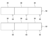
- FIG. 2 is a top view showing an example of the arrangement of the shelves in the region A in which the molds are stored
- FIG. 3 is a view of the shelves as viewed from the front.
- a plurality of shelves 30 are typically arranged in the area A in which the molds are stored.
- the plurality of shelves 30 are typically provided with spaces in which a plurality of molds 40 can be stored.
- a name plate 51 engraved with a QR code (registered trademark) including information for specifying the mold 40 is attached to a predetermined position of each mold 40.
- the information for specifying the mold includes a mold asset number, a mold management number, a product number, product information, and the like.
- the mold asset number is a number for each mold attached to the tubular book.
- the mold management number is a number assigned to each mold on the side where the mold is stored.
- a product number is a number given to a product produced by a mold.
- Product information is information on a product produced by a mold, for example, the name of the product.
- a name plate 52 engraved with a QR code (registered trademark) including information specifying the area of the shelf 30 is attached to a predetermined position of the area where the plurality of shelves 30 are arranged, for example, on the side surface of the shelf 30 on the passage side. Yes.
- Information specifying the area of the shelf 30 typically includes information specifying a company, a factory, and an area.
- a name plate 53 engraved with a QR code (registered trademark) including information specifying the shelf 30 is attached to a predetermined position of each shelf 30.
- the information for specifying the shelf 30 typically includes information for specifying a company, a factory, a rack, and a shelf.
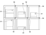
- a name plate 54 engraved with a QR code (registered trademark) including information specifying the position is attached near each position where the mold in the shelf 30 in which the mold 40 is stored is stored. Yes.
- the information for specifying the position typically includes information for specifying a company, a factory, a rack, a shelf, and in-shelf address information.
- the inventory worker B has an employee batch 55 as a display member for displaying a QR code (registered trademark) including information for identifying the inventory worker B.
- the information for specifying the inventory worker B includes information for specifying the country, company, department, and human information (employee number, etc.).
- the inventory worker B possesses the tablet terminal 20 and the employee batch 55 and performs inventory work in the area A.
- the tablet terminal 20 includes a camera 21, a microphone 22, a touch pad display unit 23, a storage unit 24, a control unit 25, and a WiFi communication unit 26.
- the camera 21 is used, for example, to photograph the nameplates 51 to 54, the QR code (registered trademark) of the employee batch 55, the mold 40, the storage state of the mold 40, and the like.
- the microphone 22 is used, for example, for recording the state of the mold 40 by voice.
- the storage unit 24 stores a program according to the present invention, for example.
- the WiFi communication unit 26 is connected to, for example, a WiFi router and performs data communication with the database 10.
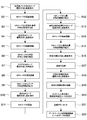
- FIG. 4 is a flowchart showing the operation of the tablet terminal 20 during inventory work.
- the tablet terminal 20 displays a screen that prompts the touch pad display unit 23 to shoot the QR code (registered trademark) of the employee batch 55 of the inventory worker (step S1).
- step S3 When the QR code (registered trademark) of the employee batch 55 is photographed and recognized (step S2), information identifying the inventory worker B is extracted from the QR code (registered trademark) (step S3).
- the tablet terminal 20 displays on the touch pad display unit 23 a screen that prompts photographing of the QR code (registered trademark) of the mold 40 to be inventoried (step S4).
- step S5 When the QR code (registered trademark) of the mold 40 is photographed and recognized (step S5), information for specifying the mold 40 is extracted from the QR code (registered trademark) (step S6).
- the tablet terminal 20 displays a screen that prompts the user to shoot the area QR code (registered trademark) on the touch pad display unit 23 (step S7).
- step S8 When the QR code (registered trademark) of the area is photographed and recognized (step S8), information for specifying the area is extracted from the QR code (registered trademark) (step S9).
- the tablet terminal 20 displays a screen for prompting photographing of the QR code (registered trademark) of the shelf 30 on the touch pad display unit 23 (step S10).
- step S11 When the QR code (registered trademark) of the shelf 30 is photographed and recognized (step S11), information specifying the shelf 30 is extracted from the QR code (registered trademark) (step S12).
- the tablet terminal 20 displays a screen for prompting the QR code (registered trademark) at the position where the mold 40 in the shelf 30 is stored on the touch pad display unit 23 (step S13).
- QR code registered trademark
- step S14 When the QR code (registered trademark) at the position where the mold 40 is stored is photographed and recognized (step S14), information specifying the position is extracted from the QR code (registered trademark) (step S15). .
- the tablet terminal 20 displays a screen for prompting photographing of the mold on the touch pad display unit 23 (step S16).
- the tablet terminal 20 displays a screen for prompting photographing of the storage state of the mold on the touch pad display unit 23 (step S18).
- the tablet terminal 20 displays an inventory inspection result sheet on the touch pad display unit 23 (step S20). Thereafter, when a predetermined button of the touch pad display unit 23 is touched (step S21), the tablet terminal 20 transmits the data of the inventory inspection result sheet to the database 10 (step S22).
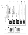
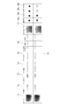
- FIG. 5 is a diagram showing a typical example of an inventory inspection result sheet displayed on the touch pad display unit 23.
- the inventory inspection result sheet 60 is automatically described when the QR code (registered trademark) is recognized and information is extracted in the tablet terminal 20 as described above.
- the inventory inspection result sheet 60 includes an inventory date display field 61, an inventory manager display field 62, an inventory mold display field 63, a mold management area display field 64a, and a mold management.
- a shelf number display column 64b, a mold shelf address number display column 64c, a mold photo display column 65, and a mold shelf photo display column 66 are provided.
- the date of entry is displayed in the inventory date display field 61.
- the inventory manager display field 62 information on the inventory operator is displayed based on the information extracted in step S3.
- step S6 information for specifying a mold based on the information extracted in step S6 is displayed.
- the molds inventoried based on the information extracted in the above steps S9, S12, and S15 are displayed. Storage location information is displayed.
- the mold photo display column 65 displays a photo of the mold taken in step S17
- the mold shelf photo display column 67 displays a photo of the mold management state taken in step S19. The Thus, the location of the mold can be determined by attaching the mold photo and the status photograph of the mold management shelf.
- the database 10 receives the data of the inventory inspection result sheet transmitted from the tablet terminal 20 and accumulates these data as mold inventory data.
- the inventory data is described in the management ledger of the mold itself and stored as a mold history (medical record).
- the inventory worker B simply performs an operation of photographing a QR code (registered trademark) using the tablet terminal 20, and the inventory worker B and the mold 40 are stored in the database 10.
- the location (area, shelf, position in the shelf), the state of the mold 40, and the storage state of the mold 40 are accumulated in association with each other. Therefore, it is possible to collect the inventory data of the mold 40 quickly and accurately without requiring labor.
- the inventory worker B is clarified, and the credibility of the report can be improved even if the inventory worker B is outsourced to the secondary subcontractor side, for example.
- the mold 40 and the photographic data of the storage state of the mold 40 in the database 10 for example, the evidence that the mold 40 exists without going to the secondary subcontractor side or overseas from the part manufacturer side is stored. Can do.
- the mold inventory data stored in the database 10 according to the present invention can be used in the purchasing department, the accounting department, the manufacturing department, the mold production engineering department, and the like.
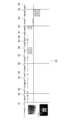
- FIG. 6 is a diagram showing a typical example of the mold inventory record of the purchasing department created based on the mold inventory data.
- the mold inventory record 70 typically includes a mold photo display field 71, a mold inventory date display field 72, a mold record manager display field 73, and a mold asset number.
- the display column 71 for the mold photo the display column 72 for the mold inventory date, the display column 73 for the person responsible for recording the mold, the display column 74 for the mold asset number, the display column 75 for the mold management number, the mold
- the data in the location management area display column 76 and the mold storage area photo display column 77 are created based on the mold inventory data stored in the database 10.
- the production approval check column 78b, the manufacturing approval check column 78c, and the accounting approval check column 78d are checked by each department.
- the mold inventory record 70 is updated with the data of the inventory inspection result sheet transmitted from the tablet terminal 20.
- the mold inventory record 70 is used for asset / location management of the entire company with the approval of each related department.
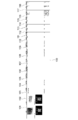
- FIG. 7 is a diagram showing a typical example of the inventory management sheet for the accounting department created based on the inventory data of the mold.
- the inventory management sheet 80 includes a mold QR sheet display field 81, an account item display field 82, a name display field 83, a mold asset management number display field 84, and an ownership display.
- Column 85 mold control number display column 86, mold start date display column 87, settlement date display column 88, acquisition amount display column 89, amortization method display column 90, useful life display column 91, current period It has a display column 92 for depreciation expenses, a display column 93 for discontinuation dates, a display column 94 for repair items, and a display column 95 for disposal dates.
- the data in the mold QR code (registered trademark) display field 81, the mold asset management number display field 84, and the mold management number display field 86 are the inventory data of the molds stored in the database 10. Created based on.
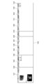
- FIG. 8 is a diagram showing a typical example of the production facility management sheet of the manufacturing department created based on the mold inventory data.
- the production facility management sheet 100 includes a mold display column 101, a processing machine display column 102, a production location display column 103, a production transfer display column 104, and a mold management number display column 105.
- Mold manufacturer display column 106 auxiliary equipment display column 107, production facility display column 108, facility management number display column 109, injection pressure display column 110, molding time display column 111, pack pressure display column It has a display column 112, a holding pressure display column 113, a temperature display column 114, a filling time display column 115, a production history display column 116, a production number display column 117, and a defect number display column 118.
- the data in the mold display column 101, the production location display column 103, the production transfer display column 104, and the mold management number display column 105 are created based on the mold inventory data stored in the database 10. Is done.
- Assets and production management are performed based on the above inventory management sheet 80 and production equipment management sheet 100.
- FIG. 9 is a diagram showing a typical example of a mold management sheet for a mold production engineering department created based on mold inventory data.
- the mold management sheet 120 includes a QR sheet display field 121, a mold management number display field 122, an asset management number display field 123, a mold manufacturer display field 124, a mold period.
- the data in the QR sheet display field 121, the mold management number display field 122, and the asset management number display field 123 is created based on the inventory data of the molds stored in the database 10.
- the data on this mold management sheet is linked to the product number and combined with the diverted parts management and mold maintenance data of the mold chart to create a chart (history) for the entire life of the mold from construction to disposal. It can also be used for the next mold design from the weak points of the mold.
- diverted parts management is to manage these data using a design database that accumulates historical data indicating that parts used for a given product have been diverted to parts of other products.
- the mold maintenance data of the mold chart is data stored in a mold maintenance database that stores a repair history of a mold corresponding to a mold number.
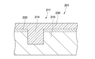
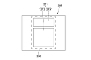
- FIG. 10 is a top view showing a configuration of a mold identification plate as a name plate engraved with a QR code (registered trademark).
- FIG. 11 is a partial longitudinal sectional view thereof.
- the mold identification plate 201 is a mold identification plate (name plate engraved with a QR code (registered trademark)) attached to the mold 40.
- the mold includes not only the mold itself but also mold parts constituting the mold. In some cases, each mold part is managed with a mold identification plate 201 attached thereto.
- the mold 40 includes various types such as a press mold, a forging mold, a casting mold, and an injection mold.
- the mold identification plate 201 includes a mold identification plate main body 210, an alumite layer 220, and an inorganic / organic composite coating layer 230.
- the mold identification plate body 210 is made of aluminum, for example, a rectangular plate-shaped member.
- the plate thickness of the mold identification plate body 210 is, for example, 1 to 1.5 mm, and may be other metals such as stainless steel in addition to aluminum.
- the mold identification plate main body 210 has a display area 211 at substantially the center thereof.
- the display area 211 includes a first display area 212 provided with a recess 214 corresponding to a QR code (registered trademark) as a two-dimensional code corresponding to information on the mold 40, and a company name, a serial number, etc. directly by visual inspection. And a second display area 213 provided with a recess 214 corresponding to information that can be confirmed. These recesses 214 are provided by, for example, cutting.
- the information about the mold 40 is as described in the above embodiment, but as another example, a server (not shown) that stores production technology information, production / facility information, and management information is accessed. This is information for accessing the production technology information, production / facility information, and management information of the individual mold among the mold information stored in the server.
- the information stored in the server may be stored in one server, or may be distributed and stored in a plurality of servers.
- the information on the mold may include, for example, information on the second display area 213 and other information in addition to the information for access described above.
- the production technology information includes, for example, a mold manufacturer, mold data, the number of production shots, mold maintenance information, and location.
- the production / equipment information includes, for example, production condition data such as molding conditions, production machine / tool specification, production line data, maintenance information such as equipment, quality information, and production environment information such as power supply / temperature / humidity.
- the management information includes, for example, a QC process chart, a work manual, and an inspection standard document.
- the depth of the recess 214 is preferably in the range of 0.1 mm to 0.2 mm, and more preferably 0.15 mm. If it is shallower than 0.1 mm, the inner side surface of the concave portion 214 may not be recognized as the concave portion 214 when it becomes a slope during processing, for example. It becomes easy and may not be recognized as the recess 214. If the depth of the concave portion 214 is around 0.15 mm, these are prevented and the QR code (registered trademark) is correctly recognized.
- the alumite layer 220 is provided on the surface of the mold identification plate main body 210 including the surface of the display area 211 so as to avoid the recess 214.
- the alumite layer 220 is provided by an alumite process described later.
- the region where the alumite layer 220 is provided is black, and the concave portion 214 is the color of the gloss of aluminum itself.
- the present invention includes any layer that makes the color difference between the surface and the recess clear.
- the anodized layer 220 is preferable. This is because the alumite layer 220 can be easily formed by an alumite treatment, and the color difference from the concave portion becomes black.
- the inorganic / organic composite coating layer 230 is made of a transparent and heat-resistant two-component room temperature curable inorganic / organic hybrid coating (for example, “FOC700 (trade name)” manufactured by FECT).
- the heat resistance is preferably in the range of 70 ° to 200 °.
- the inorganic / organic composite coating layer 230 is provided with a concave portion 214 corresponding to a QR code (registered trademark) as a two-dimensional code corresponding to information on the mold on the surface of the mold identification plate main body 210. Cover and fill the recess 214.
- the surface of the inorganic / organic composite coating layer 230 is substantially flat including the position corresponding to the recess 214.
- the inorganic / organic composite coating layer 230 preferably has a thickness of 0.1 mm to 0.2 mm as a height from the surface of the mold identification plate body 210. When the thickness is smaller than 0.1 mm, the display area 211 is not sufficiently protected by the inorganic / organic composite coating layer 230.
- the thickness is up to 0.2 mm, and the above protection is sufficient. If the thickness is larger than 0.2 mm, the coating material is wasted.
- the inorganic / organic composite coating layer 230 does not need to cover the entire area of the surface of the mold identification plate main body 210 as shown in FIG. That is, the inorganic / organic composite coating layer 230 only needs to cover at least the surface of the display region 211, and a step of applying an inorganic / organic composite coating to be described later by covering a certain area including the surface of the display region 211. This eliminates the need for strict accuracy and saves coating materials.
- the mold identification plate 201 information about the mold 40 is displayed by providing a recess 214 corresponding to a QR code (registered trademark) as a two-dimensional code in the display area 211, and the surface of the display area 211 is inorganic. Since the organic composite paint layer 230 is provided, a QR code (registered trademark) as a two-dimensional code for each individual can be attached in a simple process and can be produced in a short time.
- a QR code registered trademark
- the transparent and heat-resistant inorganic / organic composite coating layer 230 is provided with a recess 214 corresponding to the two-dimensional code so as to cover the surface of the display area 211 and fill the recess 214. Oil does not accumulate, and the recognition rate of the QR code (registered trademark) as a two-dimensional code does not decrease over a long period of time.
- the inorganic / organic composite coating layer 230 fills the recess 214, the adhesion between the inorganic / organic composite coating layer 230 and the display region 211 is increased, and durability can be maintained for a long time.
- the adhesion between the inorganic / organic composite coating layer 230 and the display region 211 is poor, gas or the like may accumulate in the concave portion 214 at the time of creation. There is a possibility that the recognition rate of the QR code (registered trademark) as a two-dimensional code is lowered. Further, if the non-attachability is poor, the inorganic / organic composite coating layer 230 may be peeled off from the display area 211 and the display area 211 may be exposed.
- This mold identification plate 201 is typically manufactured by the following method.
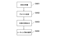
- FIG. 13 is a flowchart showing a configuration of a method for manufacturing the mold identification plate 201.
- a mold identification plate main body 210 having a plate thickness of, for example, 1 to 1.5 mm and made of rectangular and plate-shaped aluminum is prepared (step 401).
- an alumite treatment is performed on the entire surface of one side of the mold identification plate body 210 (step 402) to form an alumite layer 220.
- a recess 214 is formed by cutting to a depth of about 0.1 mm to 0.2 mm in the center of the anodized surface (surface) of the mold identification plate body 210 (step 403).
- the display area 211 is formed.
- the display area 211 includes a first display area 212 provided with a recess 214 corresponding to a QR code (registered trademark) as a two-dimensional code corresponding to information on a mold, a company name, and a serial number.
- a second display region 213 provided with a recess 214 corresponding to information that can be directly confirmed visually.
- an inorganic / organic composite paint is applied to the surface of the mold identification plate main body 210 so as to cover a certain area including the surface of the display area 211 (step 404).
- An inorganic-organic composite coating layer 230 having a thickness of about 1 mm to 0.2 mm is formed.
- the layer 230 that protects the concave portion 214 is provided, and the layer 230 is an inorganic-organic composite coating layer that is formed of an inorganic organic composite coating, so that the layer that protects the concave portion 214 is formed by a simple coating process.
- the heat resistance, durability and the like are very excellent, and the recognition rate of the two-dimensional code can be maintained for a long time.
- bubbles and the like in the recess 214 do not float on the surface and remain in the recess 214 at the time of application, and the adhesion is extremely high.
- the protective layer 230 can be formed by a simple coating process, and thus the protective layer 230 has extremely high adhesion in a simple and short process. Can be formed. Furthermore, by using a two-component room temperature curing type inorganic organic hybrid paint (for example, “FOC700 (trade name)” manufactured by FECT), transparency can be maintained over a long period of time, so that the recognition rate of a two-dimensional code is maintained over a long period of time. can do.
- a two-component room temperature curing type inorganic organic hybrid paint for example, “FOC700 (trade name)” manufactured by FECT
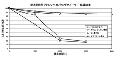
- Fig. 14 shows data disclosed by FECT regarding transparency.
- Bonde steel plate (150 x 50 x 0.3 mm) as a material as a material
- film thickness as a film thickness: 25 to 30 ⁇ m 25 to 30 ⁇ m
- curing conditions as drying at 80 ° C for 30 minutes, room temperature for 2 weeks It was served after being left.
- the material for the above-mentioned inorganic / organic composite coating layer is not limited to the illustrated material, and any material having the same function can be used in the same manner.
- the cutting of the recess in the display area is not limited to the above embodiment, and other cutting may be used.
- the above identification board can be grasped as the following technology
- An identification plate attached to an object A metal identification board body, On the surface of the identification plate main body, a recess is provided according to a two-dimensional code corresponding to information on the object, and a display area;
- An identification comprising: a transparent and heat-resistant inorganic-organic composite coating layer that covers the surface of the display area and fills the recess.
- the identification plate according to (1) The inorganic / organic composite coating layer has a heat resistance of 70 ° to 200 °.
- a method of manufacturing an identification plate attached to an object On the surface of the display area of the metal identification plate main body, a recess according to the two-dimensional code corresponding to the information on the object is provided, A transparent and heat-resistant inorganic / organic composite coating is applied to the surface of the display area provided with the recess so as to cover the surface and fill the recess.
- the inorganic-organic composite paint has a heat resistance of 70 ° to 200 °.
- the identification plate body is made of aluminum
- the method is A method for manufacturing an identification plate, wherein an alumite treatment is performed on the surface of the identification plate main body before providing a recess according to a two-dimensional code corresponding to information on the object.
- a mold is used as an example of stored items.
- inventory data of other stored items such as jigs and tools may be collected. Further, for example, when storing dies and jigs together, these storage data may be collected as inventory data.
- the jigs and tools there are typically a measurement jig and an assembly jig used in a production line.
- the storage data may be collected not only as inventory data but also for other purposes.
- the QR code (registered trademark) is engraved on the metal plate as the name plate.
- a seal-like name plate on which the QR code (registered trademark) is printed may be used.
- Mold inventory data collection system 10 Database 20 Tablet terminal 30 Shelf 40 Mold 51-54 Name plate 55 engraved with QR code (registered trademark) Employee batch
Abstract
In order to quickly and correctly collect inventory data of dies without the need to expend time and effort, an inventory operator (B) is outfitted with an employee badge (55) for displaying a QR code (registered trademark) including first information for specifying the inventory operator (B). A first nameplate (51) engraved with a QR code (registered trademark) including second information for specifying a die (40) is attached to the die (40) in a predetermined position. A second nameplate (52-54) engraved with a QR code (registered trademark) including third information for specifying a place where the die (40) is stored is attached in a predetermined position. The inventory operator (B) uses a tablet terminal (20) to acquire the information from the QR codes (registered trademark), takes an image of the die (40) and a storage state of the die (40), and accumulates the data as inventory data of the die (40) in a database (10).
Description
本発明は、金型や治工具の棚卸データなどを収集する保管物の保管データの収集方法及びプログラムに関する。
The present invention relates to a storage data collection method and a program for collecting stored items for collecting inventory data of dies and jigs.
金型は製品種の増加とともに増える一方である。またサービスパーツ(補修部品)は量産打ち切り後も保管しておく必要あるため、これを成形する金型も長期にわたり保管する必要がある。例えばサービスパーツは自動車で15年、民生品で7年、原子力等は30年に及び、その期間金型も保管する必要がある。従って、金型を使って部品を生産する企業は莫大な数の金型を保有している。しかも、国内ばかりでなく海外にも生産拠点を持つ企業では、保有する金型が各国に散在し、かつ、各国間での金型の移送も頻繁に行われている。
金 Molds are increasing as product types increase. In addition, since service parts (repair parts) must be stored even after mass production is discontinued, it is also necessary to store a mold for molding the service parts over a long period of time. For example, service parts are 15 years for automobiles, 7 years for consumer goods, and 30 years for nuclear power. Accordingly, companies that produce parts using molds have a huge number of molds. Moreover, in companies that have production bases not only in Japan but also overseas, the molds that are held are scattered in each country, and the molds are frequently transferred between countries.
従来から金型の管理は典型的にはコンピュータ上で台帳を作成し、データの入力については人手に頼っているが、現物の照合等の作業も伴い非常に手間がかかる。本発明者らは金型にQRコード(登録商標)を付与し、更に金型管理棚、生産設備、治工具管理棚、作業者などにQRコード(登録商標)を付与し、これらも金型と同じようにデータを管理する技術を提唱している(特許文献1参照)。
Conventionally, mold management typically creates a ledger on a computer and relies on humans for data input, but it is very time consuming with work such as actual verification. The present inventors give a QR code (registered trademark) to a mold, and further give a QR code (registered trademark) to a mold management shelf, a production facility, a tool management shelf, an operator, etc. The technique which manages data similarly is proposed (refer patent document 1).
自動車関連の生産形態を例にとると、完成品メーカに部品を納入する部品メーカは2次下請けに生産を委託することがある。この場合、部品メーカが保有する金型を2次下請けに貸渡すことになる。このような形態では、金型を管理し、台帳等を作成する責任主体は部品メーカである。典型的には部品メーカの購買部門がこれらの管理を行うものであるが、膨大な数の金型を保有し、更に保有する金型が各国に散在し、かつ、各国間での金型の移送も頻繁に行われている現状では、金型の棚卸しを正確にできない。そのため、金型資産台帳と保管実態とのずれが生じ、資産と実際に差異が出て財務上問題が発生する。また、部品メーカ側の担当者が国内の2次下請けや海外の工場まで見に行くことができないのが現状であり、生善説に立った管理で保管業者の報告を信用するしかない。
Taking automobile-related production forms as an example, a parts manufacturer that delivers parts to a finished product manufacturer may outsource production to a secondary subcontractor. In this case, the mold owned by the parts manufacturer is lent to the secondary subcontractor. In such a form, the responsible entity that manages the mold and creates the ledger or the like is the component manufacturer. Typically, the purchasing department of a parts manufacturer manages these, but it has a huge number of dies, and the dies that are held are scattered in each country. In the present situation where the transfer is frequently performed, it is not possible to accurately inventory the mold. For this reason, there is a difference between the mold asset ledger and the actual storage, and there is a real difference between the asset and financial problems. In addition, the current situation is that the person in charge of the parts manufacturer cannot go to the secondary subcontractors in Japan or overseas factories, and the only way to do this is to trust the storage company's report with the management based on the good faith theory.
加えて海外の政情不安や取引先の倒産、廃業で急に生産を他の業者に移管したり、日本に戻したり、いわゆる生産移管が頻発するようになった。他の要因として為替レートの変動に対応して生産地を変更する必要も発生している。
In addition, overseas societal instability, bankruptcy of business partners, and out of business suddenly transferred production to other contractors, returned to Japan, and so-called production transfer began to occur frequently. Another factor is the need to change production areas in response to exchange rate fluctuations.
以上のような事情に鑑み、本発明の目的は、手間を要することなく迅速にかつ正確に金型や治工具の棚卸データなどを収集することができる保管物の保管データの収集方法及びプログラムを提供することにある。
In view of the circumstances as described above, an object of the present invention is to provide a storage data collection method and program for collecting inventory data of dies and jigs quickly and accurately without labor. It is to provide.
上記目的を達成するため、本発明の一形態に係る保管物の保管データの収集方法は、保管物を確認する作業者に当該作業者を特定する第1の情報が含まれるQRコード(登録商標)を表示する表示部材を所持させ、前記保管物を特定する第2の情報が含まれるQRコード(登録商標)が設けられた第1の銘板を前記保管物の所定の位置に取り付け、前記保管物が保管される場所を特定する第3の情報が含まれるQRコード(登録商標)が設けられた第2の銘板を所定の位置に取り付け、前記作業者が撮影機能及びQRコード(登録商標)認識機能を有する通信端末を使って、前記表示部材に表示されたQRコード(登録商標)を撮影して撮影結果から前記第1の情報を取得し、前記第1の銘板に刻設されたQRコード(登録商標)を撮影して撮影結果から前記第2の情報を取得し、前記第2の銘板に刻設されたQRコード(登録商標)を撮影して撮影結果から前記第3の情報を取得し、前記保管物及び前記保管物の保管状態を撮影し、前記通信端末からデータベースに前記第1の情報、前記第2の情報、前記第3の情報並びに前記撮影した前記保管物及び前記保管物の保管状態の撮影データを送信し、前記データベースが前記通信端末から送信された前記第1の情報、前記第2の情報、前記第3の情報及び前記撮影データを前記保管物の保管データとして蓄積するものである。
In order to achieve the above object, a method for collecting stored data of a stored item according to an aspect of the present invention includes a QR code (registered trademark) including first information for identifying a worker who confirms the stored item. ), A first name plate provided with a QR code (registered trademark) including second information for specifying the stored item is attached to a predetermined position of the stored item, and the storage is performed. A second nameplate provided with a QR code (registered trademark) including third information for specifying a place where an object is stored is attached to a predetermined position, and the operator takes a photographing function and a QR code (registered trademark). Using a communication terminal having a recognition function, the QR code (registered trademark) displayed on the display member is photographed, the first information is obtained from the photographed result, and the QR engraved on the first nameplate is obtained. Code (registered trademark) The second information is obtained from the photographing result, the QR code (registered trademark) engraved on the second nameplate is photographed, the third information is obtained from the photographing result, and the stored item and the storage The storage state of the object is photographed, and the communication terminal transmits the first information, the second information, the third information, and the photographing data of the photographed stored material and the storage state of the stored material to the database. Then, the database accumulates the first information, the second information, the third information, and the photographing data transmitted from the communication terminal as storage data of the storage items.
典型的には前記保管物は、金型又は治工具であり、前記保管データは、棚卸データとして用いられるものである。
Typically, the stored item is a mold or a tool, and the stored data is used as inventory data.
これにより、手間を要することなく迅速にかつ正確に金型や治工具の棚卸データなどを収集することができる。
This makes it possible to collect inventory data of dies and jigs quickly and accurately without any effort.
例えば金型の棚卸データの収集方法は、以下の工程を有する。
・棚卸作業者に棚卸作業者を特定する第1の情報が含まれるQRコード(登録商標)を表示する表示部材を所持させる。
・金型を特定する第2の情報が含まれるQRコード(登録商標)が刻設された第1の銘板を金型の所定の位置に取り付ける。
・金型が保管される場所を特定する第3の情報が含まれるQRコード(登録商標)が刻設された第2の銘板を所定の位置に取り付ける。
・棚卸作業者が撮影機能及びQRコード(登録商標)認識機能を有する通信端末を使って、前記表示部材に表示されたQRコード(登録商標)を撮影して撮影結果から前記第1の情報を取得し、前記第1の銘板に刻設されたQRコード(登録商標)を撮影して撮影結果から前記第2の情報を取得し、前記第2の銘板に刻設されたQRコード(登録商標)を撮影して撮影結果から前記第3の情報を取得し、前記金型及び前記金型の保管状態を撮影し、前記通信端末からデータベースに前記第1の情報、前記第2の情報、前記第3の情報並びに前記撮影した前記金型及び前記金型の保管状態の撮影データを送信する。
・前記データベースが前記通信端末から送信された前記第1の情報、前記第2の情報、前記第3の情報及び前記撮影データを前記金型の棚卸データとして蓄積する。 For example, a mold inventory data collection method includes the following steps.
The inventory operator is made to have a display member that displays a QR code (registered trademark) including the first information for identifying the inventory operator.
A first name plate engraved with a QR code (registered trademark) including second information for specifying a mold is attached to a predetermined position of the mold.
-Attach a second name plate engraved with a QR code (registered trademark) including third information for specifying a place where the mold is stored at a predetermined position.
The inventory operator uses a communication terminal having a photographing function and a QR code (registered trademark) recognition function to photograph the QR code (registered trademark) displayed on the display member and obtains the first information from the photographing result. The QR code (registered trademark) engraved on the first nameplate is photographed, the second information is acquired from the photographing result, and the QR code (registered trademark) engraved on the second nameplate is obtained. ) And obtaining the third information from the photographing result, photographing the mold and the storage state of the mold, the first information from the communication terminal to the database, the second information, The third information and the photographed mold and the photographing data of the storage state of the mold are transmitted.
The database stores the first information, the second information, the third information, and the photographing data transmitted from the communication terminal as inventory data of the mold.
これにより、棚卸作業者は通信端末を使って実質的に撮影する作業をするだけで、データベースには、当該棚卸作業者と金型が保管されている場所と金型の状態と金型の保管状態とが関連付けられた蓄積されていく。従って、手間を要することなく迅速にかつ正確に金型の棚卸データの収集を行うことができる。またデータベースにおいて棚卸作業者を関連付けておくことで、棚卸作業者が明確にされ、例えば2次下請け側の棚卸作業者に委託しても報告の信ぴょう性を高めることができる。更にデータベースにおいて金型及び金型の保管状態の撮影データを関連付けておくことで、例えば部品メーカ側から2次下請け側や海外に出向くことなく型が存在する証拠を保存することができる。
As a result, the inventory operator simply needs to take a picture using the communication terminal, and the database stores the inventory operator, the location where the mold is stored, the state of the mold, and the storage of the mold. The state is accumulated in association with it. Therefore, it is possible to quickly and accurately collect the inventory data of the mold without requiring time and effort. Further, by associating the inventory workers in the database, the inventory workers are clarified, and the credibility of the report can be improved even if, for example, it is entrusted to an inventory operator on the secondary subcontractor side. Furthermore, by associating the mold and the storage data of the mold storage state in the database, for example, it is possible to store evidence that the mold exists without going to the secondary subcontractor or overseas from the part manufacturer side.
この形態において、前記金型が保管される場所を特定する第3の情報は、金型が保管される棚を特定する情報及び金型が保管される棚内の位置を特定する情報を含み、棚卸作業者が撮影機能及びQRコード(登録商標)認識機能を有する通信端末を使って、前記第2の銘板に刻設されたQRコード(登録商標)を撮影して撮影結果から前記第3の情報として金型が保管される棚を特定する情報及び金型が保管される棚内の位置を特定する情報を取得し、前記通信端末からデータベースに送信するものであり、前記データベースが前記第3の情報として金型が保管される棚を特定する情報及び金型が保管される棚内の位置を特定する情報を蓄積するものである。これにより、金型の保管場所をより正確に把握することができる。
In this embodiment, the third information specifying the place where the mold is stored includes information specifying the shelf where the mold is stored and information specifying the position in the shelf where the mold is stored, An inventory operator uses a communication terminal having a photographing function and a QR code (registered trademark) recognition function to photograph the QR code (registered trademark) engraved on the second nameplate and takes the third result from the photographing result. The information for identifying the shelf in which the mold is stored and the information for specifying the position in the shelf in which the mold is stored are acquired as information, and transmitted from the communication terminal to the database. As information, information for specifying a shelf in which a mold is stored and information for specifying a position in the shelf in which the mold is stored are stored. Thereby, the storage place of a metal mold | die can be grasped | ascertained more correctly.
本発明の他の形態に係るプログラムは、撮影されたそれぞれの撮影データから、保管物を保管する作業者を特定する第1の情報が含まれるQRコード(登録商標)、保管物を特定する第2の情報が含まれるQRコード(登録商標)及び保管物が保管される場所を特定する第3の情報が含まれるQRコード(登録商標)を抽出するステップと、これら抽出したそれぞれのQRコード(登録商標)から前記第1の情報、前記第2の情報及び前記第3の情報を取得するステップと、前記取得した第1、第2及び第3の情報を、前記保管物及び前記保管物の保管状態を撮影した撮影データとともに、データベースに送信させるステップと、を通信端末に実行させるものである。
A program according to another aspect of the present invention includes a QR code (registered trademark) including first information for specifying an operator who stores a stored item, and a first item for specifying a stored item, from each captured image data. The QR code (registered trademark) including the information 2 and the QR code (registered trademark) including the third information specifying the place where the stored items are stored, and the extracted QR codes ( Acquiring the first information, the second information, and the third information from the registered trademark, and obtaining the acquired first, second, and third information from the stored items and the stored items. And causing the communication terminal to execute a step of transmitting to the database together with the photographing data obtained by photographing the storage state.
例えば本発明の他の形態に係るプログラムは、プログラム撮影されたそれぞれの撮影データから、棚卸作業者を特定する第1の情報が含まれるQRコード(登録商標)、金型を特定する第2の情報が含まれるQRコード(登録商標)及び金型が保管される場所を特定する第3の情報が含まれるQRコード(登録商標)を抽出するステップと、これら抽出したそれぞれのQRコード(登録商標)から前記第1の情報、前記第2の情報及び前記第3の情報を取得するステップと、前記取得した第1、第2及び第3の情報を、金型及び金型の保管状態を撮影した撮影データとともに、データベースに送信させるステップと、を通信端末に実行させるものである。これにより、通信端末によって、手間を要することなく迅速にかつ正確に金型の棚卸データの収集を行うことができる。
For example, a program according to another embodiment of the present invention includes a QR code (registered trademark) including first information for identifying an inventory worker, and a second for identifying a mold, from each captured data captured by the program. A step of extracting a QR code (registered trademark) including information and a QR code (registered trademark) including third information for specifying a place where the mold is stored, and each extracted QR code (registered trademark) ) Acquiring the first information, the second information, and the third information, and photographing the mold and the storage state of the mold using the acquired first, second, and third information. And causing the communication terminal to execute a step of transmitting to the database together with the photographed data. As a result, the inventory data of the mold can be collected quickly and accurately by the communication terminal without any trouble.
本発明により、手間を要することなく迅速にかつ正確に金型や治工具の棚卸データなどを収集することができる。
DETAILED DESCRIPTION OF THE INVENTION According to the present invention, inventory data of dies and jigs can be collected quickly and accurately without requiring labor.
以下、図面を参照しながら、本発明の実施形態を説明する。
Hereinafter, embodiments of the present invention will be described with reference to the drawings.
〈システム構成〉
図1は、本発明の一実施形態に係る金型の棚卸データの収集システムの構成を示す図である。 <System configuration>
FIG. 1 is a diagram showing a configuration of a mold inventory data collection system according to an embodiment of the present invention.
図1は、本発明の一実施形態に係る金型の棚卸データの収集システムの構成を示す図である。 <System configuration>
FIG. 1 is a diagram showing a configuration of a mold inventory data collection system according to an embodiment of the present invention.
図1に示すように、金型の棚卸データの収集システム1は、金型の棚卸データを蓄積するデータベース10と、金型が収納された領域Aで棚卸を行う棚卸作業者Bが所持するタブレット端末20とを有する。例えばデータベース10は部品メーカ側に配置され、タブレット端末20は2次下請け側で棚卸作業者Bにより所持される。
As shown in FIG. 1, a mold inventory data collection system 1 includes a database 10 for storing mold inventory data and a tablet possessed by an inventory worker B who performs inventory in an area A in which molds are stored. Terminal 20. For example, the database 10 is arranged on the part manufacturer side, and the tablet terminal 20 is possessed by the inventory operator B on the secondary subcontractor side.
データベース10とタブレット端末20とはWiFiなどの無線通信路及び有線通信路などを介してデータ通信が可能となっている。なお、タブレット端末は本発明に係る通信端末の一形態であり、撮影機能及びQRコード(登録商標)認識機能を有するスマートフォンやPC等の他の通信端末であっても良い。
The data communication between the database 10 and the tablet terminal 20 is possible via a wireless communication path such as WiFi and a wired communication path. The tablet terminal is a form of the communication terminal according to the present invention, and may be another communication terminal such as a smartphone or a PC having a photographing function and a QR code (registered trademark) recognition function.
図2は金型が収納された領域Aでの棚の配置の例を示す上面図であり、図3はその棚を正面から見た図である。
FIG. 2 is a top view showing an example of the arrangement of the shelves in the region A in which the molds are stored, and FIG. 3 is a view of the shelves as viewed from the front.
図2及び図3に示すように、金型が収納された領域Aには、典型的には複数の棚30が列設されている。複数の棚30には、典型的には複数の金型40が収納可能なスペースが設けられている。
As shown in FIGS. 2 and 3, a plurality of shelves 30 are typically arranged in the area A in which the molds are stored. The plurality of shelves 30 are typically provided with spaces in which a plurality of molds 40 can be stored.
各金型40の所定の位置には、金型40を特定する情報が含まれるQRコード(登録商標)が刻設された銘板51が取り付けられている。金型を特定する情報には、金型資産番号、金型管理番号、製品番号、製品情報などが含まれる。ここで、金型資産番号とは、管型の帳簿に付される各金型に対する番号である。金型管理番号とは、金型を保管する側で各金型に付される番号である。製品番号とは、金型によって生産された製品に付される番号である。製品情報とは、金型によって生産された製品の情報、例えば当該製品の名称である。
A name plate 51 engraved with a QR code (registered trademark) including information for specifying the mold 40 is attached to a predetermined position of each mold 40. The information for specifying the mold includes a mold asset number, a mold management number, a product number, product information, and the like. Here, the mold asset number is a number for each mold attached to the tubular book. The mold management number is a number assigned to each mold on the side where the mold is stored. A product number is a number given to a product produced by a mold. Product information is information on a product produced by a mold, for example, the name of the product.
複数の棚30が並ぶエリアの所定の位置例えば通路側の棚30の側面には、棚30のエリアを特定する情報が含まれるQRコード(登録商標)が刻設された銘板52が取り付けられている。棚30のエリアを特定する情報には、典型的には会社、工場、エリアを特定する情報などが含まれる。
A name plate 52 engraved with a QR code (registered trademark) including information specifying the area of the shelf 30 is attached to a predetermined position of the area where the plurality of shelves 30 are arranged, for example, on the side surface of the shelf 30 on the passage side. Yes. Information specifying the area of the shelf 30 typically includes information specifying a company, a factory, and an area.
各棚30の所定の位置には、棚30を特定する情報が含まれるQRコード(登録商標)が刻設された銘板53が取り付けられている。棚30を特定する情報には、典型的には会社、工場、ラック、棚を特定する情報などが含まれる。
A name plate 53 engraved with a QR code (registered trademark) including information specifying the shelf 30 is attached to a predetermined position of each shelf 30. The information for specifying the shelf 30 typically includes information for specifying a company, a factory, a rack, and a shelf.
金型40が収容される棚30内の金型が保管される各位置の近くには、当該位置を特定する情報が含まれるQRコード(登録商標)が刻設された銘板54が取り付けられている。位置を特定する情報には、典型的には会社、工場、ラック、棚を特定する情報及び棚内番地情報が含まれる。
A name plate 54 engraved with a QR code (registered trademark) including information specifying the position is attached near each position where the mold in the shelf 30 in which the mold 40 is stored is stored. Yes. The information for specifying the position typically includes information for specifying a company, a factory, a rack, a shelf, and in-shelf address information.
棚卸作業者Bは当該棚卸作業者Bを特定する情報が含まれるQRコード(登録商標)を表示する表示部材としての従業員バッチ55を所持する。棚卸作業者Bを特定する情報には、国、会社、部署を特定する情報及び人情報(社員番号など)などが含まれる。棚卸作業者Bはタブレット端末20及びこの従業員バッチ55を所持して領域Aにおいて棚卸の作業を行う。
The inventory worker B has an employee batch 55 as a display member for displaying a QR code (registered trademark) including information for identifying the inventory worker B. The information for specifying the inventory worker B includes information for specifying the country, company, department, and human information (employee number, etc.). The inventory worker B possesses the tablet terminal 20 and the employee batch 55 and performs inventory work in the area A.
〈タブレット端末20側〉
図1に示したように、タブレット端末20は、カメラ21と、マイク22と、タッチパット表示部23と、記憶部24と、制御部25と、WiFi通信部26とを有する。 <Tablet terminal 20 side>
As illustrated in FIG. 1, thetablet terminal 20 includes a camera 21, a microphone 22, a touch pad display unit 23, a storage unit 24, a control unit 25, and a WiFi communication unit 26.
図1に示したように、タブレット端末20は、カメラ21と、マイク22と、タッチパット表示部23と、記憶部24と、制御部25と、WiFi通信部26とを有する。 <
As illustrated in FIG. 1, the
カメラ21は例えば銘板51~54や従業員バッチ55のQRコード(登録商標)、型40や型40の保管状態などを撮影するために用いられる。マイク22は例えば金型40の状態などを音声で録音するために用いられる。記憶部24は例えば本発明に係るプログラムを記憶する。WiFi通信部26は例えばWiFiルータなどに接続され、データベース10との間でデータ通信を行う。
The camera 21 is used, for example, to photograph the nameplates 51 to 54, the QR code (registered trademark) of the employee batch 55, the mold 40, the storage state of the mold 40, and the like. The microphone 22 is used, for example, for recording the state of the mold 40 by voice. The storage unit 24 stores a program according to the present invention, for example. The WiFi communication unit 26 is connected to, for example, a WiFi router and performs data communication with the database 10.
図4は棚卸作業時のタブレット端末20の動作を示すフローチャートである。
FIG. 4 is a flowchart showing the operation of the tablet terminal 20 during inventory work.
タブレット端末20はタッチパット表示部23に棚卸作業者の従業員バッチ55のQRコード(登録商標)の撮影を促す画面を表示する(ステップS1)。
The tablet terminal 20 displays a screen that prompts the touch pad display unit 23 to shoot the QR code (registered trademark) of the employee batch 55 of the inventory worker (step S1).
従業員バッチ55のQRコード(登録商標)が撮影され、認識されると(ステップS2)、そのQRコード(登録商標)から棚卸作業者Bを特定する情報を抽出する(ステップS3)。
When the QR code (registered trademark) of the employee batch 55 is photographed and recognized (step S2), information identifying the inventory worker B is extracted from the QR code (registered trademark) (step S3).
次に、タブレット端末20はタッチパット表示部23に棚卸対象の金型40のQRコード(登録商標)の撮影を促す画面を表示する(ステップS4)。
Next, the tablet terminal 20 displays on the touch pad display unit 23 a screen that prompts photographing of the QR code (registered trademark) of the mold 40 to be inventoried (step S4).
金型40のQRコード(登録商標)が撮影され、認識されると(ステップS5)、そのQRコード(登録商標)から金型40を特定する情報を抽出する(ステップS6)。
When the QR code (registered trademark) of the mold 40 is photographed and recognized (step S5), information for specifying the mold 40 is extracted from the QR code (registered trademark) (step S6).
次に、タブレット端末20はタッチパット表示部23にエリアのQRコード(登録商標)の撮影を促す画面を表示する(ステップS7)。
Next, the tablet terminal 20 displays a screen that prompts the user to shoot the area QR code (registered trademark) on the touch pad display unit 23 (step S7).
エリアのQRコード(登録商標)が撮影され、認識されると(ステップS8)、そのQRコード(登録商標)からエリアを特定する情報を抽出する(ステップS9)。
When the QR code (registered trademark) of the area is photographed and recognized (step S8), information for specifying the area is extracted from the QR code (registered trademark) (step S9).
次に、タブレット端末20はタッチパット表示部23に棚30のQRコード(登録商標)の撮影を促す画面を表示する(ステップS10)。
Next, the tablet terminal 20 displays a screen for prompting photographing of the QR code (registered trademark) of the shelf 30 on the touch pad display unit 23 (step S10).
棚30のQRコード(登録商標)が撮影され、認識されると(ステップS11)、そのQRコード(登録商標)から棚30を特定する情報を抽出する(ステップS12)。
When the QR code (registered trademark) of the shelf 30 is photographed and recognized (step S11), information specifying the shelf 30 is extracted from the QR code (registered trademark) (step S12).
次に、タブレット端末20はタッチパット表示部23に棚30内の金型40が保管されている位置のQRコード(登録商標)の撮影を促す画面を表示する(ステップS13)。
Next, the tablet terminal 20 displays a screen for prompting the QR code (registered trademark) at the position where the mold 40 in the shelf 30 is stored on the touch pad display unit 23 (step S13).
金型40が保管されている位置のQRコード(登録商標)が撮影され、認識されると(ステップS14)、そのQRコード(登録商標)から当該位置を特定する情報を抽出する(ステップS15)。
When the QR code (registered trademark) at the position where the mold 40 is stored is photographed and recognized (step S14), information specifying the position is extracted from the QR code (registered trademark) (step S15). .
次に、タブレット端末20はタッチパット表示部23に当該金型の撮影を促す画面を表示する(ステップS16)。金型40が撮影されると(ステップS17)、タブレット端末20はタッチパット表示部23に当該金型の保管状態の撮影を促す画面を表示する(ステップS18)。
Next, the tablet terminal 20 displays a screen for prompting photographing of the mold on the touch pad display unit 23 (step S16). When the mold 40 is photographed (step S17), the tablet terminal 20 displays a screen for prompting photographing of the storage state of the mold on the touch pad display unit 23 (step S18).
金型40の保管状態が撮影されると(ステップS19)、タブレット端末20はタッチパット表示部23に棚卸検査結果シートを表示する(ステップS20)。その後、タブレット端末20はタッチパット表示部23の所定のボタンがタッチされると(ステップS21)、棚卸検査結果シートのデータをデータベース10に送信する(ステップS22)。
When the storage state of the mold 40 is photographed (step S19), the tablet terminal 20 displays an inventory inspection result sheet on the touch pad display unit 23 (step S20). Thereafter, when a predetermined button of the touch pad display unit 23 is touched (step S21), the tablet terminal 20 transmits the data of the inventory inspection result sheet to the database 10 (step S22).
図5はタッチパット表示部23に表示される棚卸検査結果シートの典型例を示す図である。
FIG. 5 is a diagram showing a typical example of an inventory inspection result sheet displayed on the touch pad display unit 23.
図5に示すように、棚卸検査結果シート60は、上記のようにタブレット端末20においてQRコード(登録商標)が認識され情報が抽出されると、自動的に内容が記載される。
As shown in FIG. 5, the inventory inspection result sheet 60 is automatically described when the QR code (registered trademark) is recognized and information is extracted in the tablet terminal 20 as described above.
典型的には、棚卸検査結果シート60は、棚卸年月日表示欄61と、棚卸責任者表示欄62と、棚卸金型表示欄63と、金型管理エリアの表示欄64aと、金型管理棚番号表示欄64bと、金型棚番地番号表示欄64cと、金型写真表示欄65と、金型棚写真表示欄66とを有する。
Typically, the inventory inspection result sheet 60 includes an inventory date display field 61, an inventory manager display field 62, an inventory mold display field 63, a mold management area display field 64a, and a mold management. A shelf number display column 64b, a mold shelf address number display column 64c, a mold photo display column 65, and a mold shelf photo display column 66 are provided.
ここで、棚卸年月日表示欄61には入力が行われた年月日が表示される。棚卸責任者表示欄62には、上記のステップS3で抽出された情報に基づき棚卸作業者の情報が表示される。
Here, the date of entry is displayed in the inventory date display field 61. In the inventory manager display field 62, information on the inventory operator is displayed based on the information extracted in step S3.
棚卸金型表示欄63には、上記のステップS6で抽出された情報に基づき金型を特定する情報が表示される。
In the inventory mold display column 63, information for specifying a mold based on the information extracted in step S6 is displayed.
金型管理エリアの表示欄64a、金型管理棚番号表示欄64b及び金型棚番地番号表示欄64cには、上記のステップS9、S12、S15で抽出された情報に基づき棚卸された金型の保管場所の情報が表示される。
In the mold management area display field 64a, the mold management shelf number display field 64b, and the mold shelf address number display field 64c, the molds inventoried based on the information extracted in the above steps S9, S12, and S15 are displayed. Storage location information is displayed.
以上の各欄61、62、63、64a、64b、64cには撮影されたQRコード(登録商標)そのものも表示される。
In each of the above fields 61, 62, 63, 64a, 64b, and 64c, the captured QR code (registered trademark) itself is also displayed.
また金型写真表示欄65には、ステップS17で撮影された金型の写真が表示され、金型棚写真表示欄67には、ステップS19で撮影された金型の管理状態の写真が表示される。このように金型写真や金型管理棚の状況写真も添付されることで、金型の所在が確定できる。
The mold photo display column 65 displays a photo of the mold taken in step S17, and the mold shelf photo display column 67 displays a photo of the mold management state taken in step S19. The Thus, the location of the mold can be determined by attaching the mold photo and the status photograph of the mold management shelf.
以上の各欄61、62、63、64a、64b、64c、65、66において、未入力は〇が表示され、入力済みは●が表示される。このような表示を行うことで、棚卸作業者Bは入力漏れを容易にチェックすることができる。
In each of the above-mentioned columns 61, 62, 63, 64a, 64b, 64c, 65, 66, ◯ is displayed when not input, and ● is displayed when input is completed. By performing such display, the inventory worker B can easily check for input omissions.
〈データベース10側〉
データベース10は、タブレット端末20より送信された棚卸検査結果シートのデータを受信し、これらのデータを金型の棚卸データとして蓄積される。棚卸データは、金型そのものの管理台帳に記載され、金型履歴(カルテ)として保存される。 <Database 10 side>
Thedatabase 10 receives the data of the inventory inspection result sheet transmitted from the tablet terminal 20 and accumulates these data as mold inventory data. The inventory data is described in the management ledger of the mold itself and stored as a mold history (medical record).
データベース10は、タブレット端末20より送信された棚卸検査結果シートのデータを受信し、これらのデータを金型の棚卸データとして蓄積される。棚卸データは、金型そのものの管理台帳に記載され、金型履歴(カルテ)として保存される。 <
The
従って、棚卸作業者Bはタブレット端末20を使って実質的にQRコード(登録商標)などを撮影する作業をするだけで、データベース10には当該棚卸作業者Bと金型40が保管されている場所(エリア、棚、棚内の位置)と金型40の状態と金型40の保管状態とが関連付けられた蓄積されていく。従って、手間を要することなく迅速にかつ正確に金型40の棚卸データの収集を行うことができる。またデータベース10において棚卸作業者Bを関連付けておくことで、棚卸作業者Bが明確にされ、例えば2次下請け側の棚卸作業者Bに委託しても報告の信ぴょう性を高めることができる。更にデータベース10において金型40及び金型40の保管状態の撮影データを関連付けておくことで、例えば部品メーカ側から2次下請け側や海外に出向くことなく金型40が存在する証拠を保存することができる。
Accordingly, the inventory worker B simply performs an operation of photographing a QR code (registered trademark) using the tablet terminal 20, and the inventory worker B and the mold 40 are stored in the database 10. The location (area, shelf, position in the shelf), the state of the mold 40, and the storage state of the mold 40 are accumulated in association with each other. Therefore, it is possible to collect the inventory data of the mold 40 quickly and accurately without requiring labor. Further, by associating the inventory worker B in the database 10, the inventory worker B is clarified, and the credibility of the report can be improved even if the inventory worker B is outsourced to the secondary subcontractor side, for example. Further, by associating the mold 40 and the photographic data of the storage state of the mold 40 in the database 10, for example, the evidence that the mold 40 exists without going to the secondary subcontractor side or overseas from the part manufacturer side is stored. Can do.
本発明に係るデータベース10に蓄積された金型の棚卸データは購買部門、経理部門、製造部門、金型生産技術部門などで利用することができる。
The mold inventory data stored in the database 10 according to the present invention can be used in the purchasing department, the accounting department, the manufacturing department, the mold production engineering department, and the like.
図6は金型の棚卸データに基づき作成される購買部門の金型棚卸記録の典型例を示す図である。
FIG. 6 is a diagram showing a typical example of the mold inventory record of the purchasing department created based on the mold inventory data.
図6に示すように、金型棚卸記録70は、典型的には、金型写真の表示欄71、金型棚卸日の表示欄72、金型記録責任者の表示欄73、金型資産番号の表示欄74、金型管理番号の表示欄75、金型所在管理エリアの表示欄76、金型保管エリア写真の表示欄77、購買承認チェック欄78a、生技承認チェック欄78b、製造承認チェック欄78c、経理承認チェック欄78dを有する。
As shown in FIG. 6, the mold inventory record 70 typically includes a mold photo display field 71, a mold inventory date display field 72, a mold record manager display field 73, and a mold asset number. Display column 74, mold control number display column 75, mold location management area display column 76, mold storage area photo display column 77, purchase approval check column 78a, production approval check column 78b, manufacturing approval check A column 78c and an accounting approval check column 78d.
このうち、金型写真の表示欄71、金型棚卸日の表示欄72、金型記録責任者の表示欄73、金型資産番号の表示欄74、金型管理番号の表示欄75、金型所在管理エリアの表示欄76、金型保管エリア写真の表示欄77のデータは、データベース10に蓄積された金型の棚卸データに基づき作成される。生技承認チェック欄78b、製造承認チェック欄78c、経理承認チェック欄78dは、各部門によりチェックがされる。
Among these, the display column 71 for the mold photo, the display column 72 for the mold inventory date, the display column 73 for the person responsible for recording the mold, the display column 74 for the mold asset number, the display column 75 for the mold management number, the mold The data in the location management area display column 76 and the mold storage area photo display column 77 are created based on the mold inventory data stored in the database 10. The production approval check column 78b, the manufacturing approval check column 78c, and the accounting approval check column 78d are checked by each department.
金型棚卸記録70はタブレット端末20より送信された棚卸検査結果シートのデータにより更新される。
The mold inventory record 70 is updated with the data of the inventory inspection result sheet transmitted from the tablet terminal 20.
金型棚卸記録70は、各関連部門の承認を得ることで会社全体の資産・所在管理に用いられる。
The mold inventory record 70 is used for asset / location management of the entire company with the approval of each related department.
図7は金型の棚卸データに基づき作成される経理部門の棚卸資産管理シートの典型例を示す図である。
FIG. 7 is a diagram showing a typical example of the inventory management sheet for the accounting department created based on the inventory data of the mold.
図7に示すように、棚卸資産管理シート80は、金型QRシートの表示欄81、勘定科目の表示欄82、名称の表示欄83、金型資産管理番号の表示欄84、所有権の表示欄85、金型管理番号の表示欄86、金型起工日の表示欄87、決算日の表示欄88、取得金額の表示欄89、償却方法の表示欄90、耐用年数の表示欄91、当期償却費の表示欄92、打ち切り日の表示欄93、補修品対応の表示欄94、廃却日の表示欄95を有する。
As shown in FIG. 7, the inventory management sheet 80 includes a mold QR sheet display field 81, an account item display field 82, a name display field 83, a mold asset management number display field 84, and an ownership display. Column 85, mold control number display column 86, mold start date display column 87, settlement date display column 88, acquisition amount display column 89, amortization method display column 90, useful life display column 91, current period It has a display column 92 for depreciation expenses, a display column 93 for discontinuation dates, a display column 94 for repair items, and a display column 95 for disposal dates.
このうち、金型QRコード(登録商標)の表示欄81、金型資産管理番号の表示欄84、金型管理番号の表示欄86のデータは、データベース10に蓄積された金型の棚卸データに基づき作成される。
Of these, the data in the mold QR code (registered trademark) display field 81, the mold asset management number display field 84, and the mold management number display field 86 are the inventory data of the molds stored in the database 10. Created based on.
図8は金型の棚卸データに基づき作成される製造部門の生産設備管理シートの典型例を示す図である。
FIG. 8 is a diagram showing a typical example of the production facility management sheet of the manufacturing department created based on the mold inventory data.
図8に示すように、生産設備管理シート100は、金型の表示欄101、加工機の表示欄102、生産場所の表示欄103、生産移管の表示欄104、金型管理番号の表示欄105、金型製造メーカの表示欄106、補機設備の表示欄107、生産設備の表示欄108、設備管理番号の表示欄109、射出圧力の表示欄110、成形時間の表示欄111、パック圧の表示欄112、保圧の表示欄113、温度の表示欄114、充填時間の表示欄115、生産履歴の表示欄116、生産数の表示欄117、不良数の表示欄118を有する。
As shown in FIG. 8, the production facility management sheet 100 includes a mold display column 101, a processing machine display column 102, a production location display column 103, a production transfer display column 104, and a mold management number display column 105. , Mold manufacturer display column 106, auxiliary equipment display column 107, production facility display column 108, facility management number display column 109, injection pressure display column 110, molding time display column 111, pack pressure display column It has a display column 112, a holding pressure display column 113, a temperature display column 114, a filling time display column 115, a production history display column 116, a production number display column 117, and a defect number display column 118.
このうち、金型の表示欄101、生産場所の表示欄103、生産移管の表示欄104、金型管理番号の表示欄105のデータは、データベース10に蓄積された金型の棚卸データに基づき作成される。
Of these, the data in the mold display column 101, the production location display column 103, the production transfer display column 104, and the mold management number display column 105 are created based on the mold inventory data stored in the database 10. Is done.
以上の棚卸資産管理シート80や生産設備管理シート100に基づき資産や生産管理がされる。
Assets and production management are performed based on the above inventory management sheet 80 and production equipment management sheet 100.
図9は金型の棚卸データに基づき作成される金型生産技術部門の金型管理シートの典型例を示す図である。
FIG. 9 is a diagram showing a typical example of a mold management sheet for a mold production engineering department created based on mold inventory data.
図9に示すように、金型管理シート120は、QRシートの表示欄121、金型管理番号の表示欄122、資産管理番号の表示欄123、金型製造メーカの表示欄124、金型期工日の表示欄125、廃棄日の表示欄126、所有権の表示欄127、部品名の表示欄128、部品番号の表示欄129、使用製品1の表示欄130、使用製品2の表示欄131、金型仕様書No.の表示欄132、設備仕様書No.の表示欄133、メンテ履歴の表示欄134を有する。
As shown in FIG. 9, the mold management sheet 120 includes a QR sheet display field 121, a mold management number display field 122, an asset management number display field 123, a mold manufacturer display field 124, a mold period. Work date display field 125, disposal date display field 126, ownership display field 127, part name display field 128, part number display field 129, used product 1 display field 130, used product 2 display field 131 , Mold specification No. No. display column 132, equipment specification No. Display column 133 and maintenance history display column 134.
このうち、QRシートの表示欄121、金型管理番号の表示欄122、資産管理番号の表示欄123のデータは、データベース10に蓄積された金型の棚卸データに基づき作成される。
Among these, the data in the QR sheet display field 121, the mold management number display field 122, and the asset management number display field 123 is created based on the inventory data of the molds stored in the database 10.
この金型管理シートのデータは、製品番号と連動させ、流用部品管理や金型カルテの金型メンテンスデータと組み合わせて金型の期工から廃棄までの一生をカルテ(履歴)化することで金型のウイークポイントから次の金型設計に役立てることもできる。
The data on this mold management sheet is linked to the product number and combined with the diverted parts management and mold maintenance data of the mold chart to create a chart (history) for the entire life of the mold from construction to disposal. It can also be used for the next mold design from the weak points of the mold.
ここで、流用部品管理とは、所定の製品に使用された部品を他の製品の部品に流用したことを示す履歴データを蓄積する設計データベースを使ってこれらのデータを管理することである。また金型カルテの金型メンテンスデータとは、金型番号に対応させた金型の修理履歴などを蓄積する金型メンテンスデータベースに蓄積されたデータのことである。
Here, diverted parts management is to manage these data using a design database that accumulates historical data indicating that parts used for a given product have been diverted to parts of other products. The mold maintenance data of the mold chart is data stored in a mold maintenance database that stores a repair history of a mold corresponding to a mold number.
〈QRコード(登録商標)が刻設された銘板〉
上記実施形態におけるQRコード(登録商標)が刻設された銘板の典型例を説明する。 <Name plate engraved with QR code (registered trademark)>
A typical example of a nameplate engraved with a QR code (registered trademark) in the above embodiment will be described.
上記実施形態におけるQRコード(登録商標)が刻設された銘板の典型例を説明する。 <Name plate engraved with QR code (registered trademark)>
A typical example of a nameplate engraved with a QR code (registered trademark) in the above embodiment will be described.
図10はQRコード(登録商標)が刻設された銘板としての金型識別板の構成を示す上面図である。図11はその一部縦断面図である。
FIG. 10 is a top view showing a configuration of a mold identification plate as a name plate engraved with a QR code (registered trademark). FIG. 11 is a partial longitudinal sectional view thereof.
図10及び図11に示すように、金型識別板201は、金型40に取り付けられる金型識別板(QRコード(登録商標)が刻設された銘板)である。ここで、金型には、金型自体の他に、金型を構成する金型部品も含まれる。金型部品もそれぞれ金型識別板201が取り付けられて管理される場合もある。金型40には、プレス金型、鍛造型、鋳造型、射出成形型等の様々なものが含まれる。
As shown in FIGS. 10 and 11, the mold identification plate 201 is a mold identification plate (name plate engraved with a QR code (registered trademark)) attached to the mold 40. Here, the mold includes not only the mold itself but also mold parts constituting the mold. In some cases, each mold part is managed with a mold identification plate 201 attached thereto. The mold 40 includes various types such as a press mold, a forging mold, a casting mold, and an injection mold.
金型識別板201は、金型識別板本体210と、アルマイト層220と、無機有機複合塗料層230とを有する。
The mold identification plate 201 includes a mold identification plate main body 210, an alumite layer 220, and an inorganic / organic composite coating layer 230.
金型識別板本体210は、アルミニウムからなり、例えば矩形で板状の部材である。金型識別板本体210の板厚は、例えば1~1.5mmであり、アルミニウム以外に例えばステンレスなどの他の金属であってもよい。
The mold identification plate body 210 is made of aluminum, for example, a rectangular plate-shaped member. The plate thickness of the mold identification plate body 210 is, for example, 1 to 1.5 mm, and may be other metals such as stainless steel in addition to aluminum.
金型識別板本体210は、そのほぼ中央に表示領域211を有する。
The mold identification plate main body 210 has a display area 211 at substantially the center thereof.
表示領域211は、金型40に関する情報に対応する二次元コードとしてのQRコード(登録商標)に応じた凹部214が設けられた第1の表示領域212と、社名やシリアルナンバ等を目視により直接確認できる情報に応じた凹部214が設けられた第2の表示領域213とを有する。これらの凹部214は、例えば切削加工により設けられる。
The display area 211 includes a first display area 212 provided with a recess 214 corresponding to a QR code (registered trademark) as a two-dimensional code corresponding to information on the mold 40, and a company name, a serial number, etc. directly by visual inspection. And a second display area 213 provided with a recess 214 corresponding to information that can be confirmed. These recesses 214 are provided by, for example, cutting.
金型40に関する情報とは、すでに上記実施形態で説明したとおりであるが、このほかの例として生産技術情報、生産・設備情報、管理情報を蓄積するサーバ(図示せず)にアクセスし、そのサーバに蓄積された金型の情報のうち当該金型個体の生産技術情報、生産・設備情報、管理情報にアクセスするための情報である。サーバに蓄積された情報としては、一つのサーバに蓄積されていてもよく、或いは複数のサーバに分散して蓄積されていてもよい。金型に関する情報は、上記のアクセスのための情報以外に、例えば第2の表示領域213の情報やその他の情報を含んでいてもよい。
The information about the mold 40 is as described in the above embodiment, but as another example, a server (not shown) that stores production technology information, production / facility information, and management information is accessed. This is information for accessing the production technology information, production / facility information, and management information of the individual mold among the mold information stored in the server. The information stored in the server may be stored in one server, or may be distributed and stored in a plurality of servers. The information on the mold may include, for example, information on the second display area 213 and other information in addition to the information for access described above.
ここで、生産技術情報として、例えば金型の製造業者、金型データ、生産ショット数、金型メンテナンス情報、所在などがある。また、生産・設備情報としては、例えば成形条件などの製造条件データ、生産機・治工具仕様、生産ラインデータ、設備等メンテ情報や品質情報、電源・温湿度などの生産環境情報などである。管理情報としては、例えばQC工程表や作業マニュアル、検査基準書などである。
Here, the production technology information includes, for example, a mold manufacturer, mold data, the number of production shots, mold maintenance information, and location. The production / equipment information includes, for example, production condition data such as molding conditions, production machine / tool specification, production line data, maintenance information such as equipment, quality information, and production environment information such as power supply / temperature / humidity. The management information includes, for example, a QC process chart, a work manual, and an inspection standard document.
上記凹部214の深さは、0.1mm~0.2mmの範囲にあることが好ましてく、0.15mmがより好適である。0.1mmよりも浅いと、凹部214の内側側面が例えば加工時に斜面となったときに凹部214として認識されないおそれがあり、また0.2mmよりも深いと、凹部の内側上部の角部が崩れやすくなり、凹部214として認識されないおそれがある。上記凹部214の深さは、0.15mm前後であれば、それらのことを防止してQRコード(登録商標)が正しく認識される。
The depth of the recess 214 is preferably in the range of 0.1 mm to 0.2 mm, and more preferably 0.15 mm. If it is shallower than 0.1 mm, the inner side surface of the concave portion 214 may not be recognized as the concave portion 214 when it becomes a slope during processing, for example. It becomes easy and may not be recognized as the recess 214. If the depth of the concave portion 214 is around 0.15 mm, these are prevented and the QR code (registered trademark) is correctly recognized.
アルマイト層220は、凹部214を避けるように表示領域211の表面を含めた金型識別板本体210の表面に設けられている。アルマイト層220は、後述するアルマイト処理により設けられる。金型識別板本体210を上面より表面を見ると、アルマイト層220が設けられた領域は黒色、凹部214はアルミニウムの光沢そのものの色となる。本発明は、アルマイト層以外にも、表面と凹部との色の差が明瞭になる層であればそれも含むものである。しかしながら、金型識別板本体210がアルミニウムからなる場合には、アルマイト層220とすることが好ましい。アルマイト層220はアルマイト処理により容易に形成でき、しかも凹部との色の差が明瞭になる黒色となるからである。
The alumite layer 220 is provided on the surface of the mold identification plate main body 210 including the surface of the display area 211 so as to avoid the recess 214. The alumite layer 220 is provided by an alumite process described later. When the surface of the mold identification plate main body 210 is viewed from the upper surface, the region where the alumite layer 220 is provided is black, and the concave portion 214 is the color of the gloss of aluminum itself. In addition to the alumite layer, the present invention includes any layer that makes the color difference between the surface and the recess clear. However, when the mold identification plate main body 210 is made of aluminum, the anodized layer 220 is preferable. This is because the alumite layer 220 can be easily formed by an alumite treatment, and the color difference from the concave portion becomes black.
無機有機複合塗料層230は、透明で耐熱性を有する二液常温硬化型無機有機ハイブリッド塗料(例えば、FECT社製「FOC700(商品名)」)からなる。耐熱性は、70°~200°の温度の範囲であることが好ましい。これにより、金型が厳しい熱的な環境で使用され、或いは保管される場合等であっても無機有機複合塗料層230が破壊等されることはなく、長期にわたり2次元コードとしてのQRコード(登録商標)の認識率が低下することはない。
The inorganic / organic composite coating layer 230 is made of a transparent and heat-resistant two-component room temperature curable inorganic / organic hybrid coating (for example, “FOC700 (trade name)” manufactured by FECT). The heat resistance is preferably in the range of 70 ° to 200 °. Thus, even when the mold is used or stored in a severe thermal environment, the inorganic / organic composite coating layer 230 is not destroyed, and the QR code (2D code) is used for a long time. The recognition rate of (registered trademark) does not decrease.
無機有機複合塗料層230は、金型識別板本体210の表面に、金型に関する情報に対応する二次元コードとしてのQRコード(登録商標)に応じた凹部214が設けられ表示領域211の表面を覆い、かつ、凹部214を埋める。無機有機複合塗料層230は、その表面が凹部214に対応する位置も含めてほぼ平坦である。また、無機有機複合塗料層230は、金型識別板本体210の表面よりの高さとしての厚みが0.1mm~0.2mmが好ましい範囲である。その厚みが0.1mmよりも小さいと、無機有機複合塗料層230による表示領域211の保護が不十分となる。例えば、無機有機複合塗料層230が割れて表示領域211が表面に露出する可能性や無機有機複合塗料層230を介して表示領域211の凹部214に機械的な悪影響を及ぼすおそれがある。一方、その厚みは0.2mmまでで上記の保護は十分であり、その厚みが0.2mmよりも大きいとコーティング材料が無駄になる。
The inorganic / organic composite coating layer 230 is provided with a concave portion 214 corresponding to a QR code (registered trademark) as a two-dimensional code corresponding to information on the mold on the surface of the mold identification plate main body 210. Cover and fill the recess 214. The surface of the inorganic / organic composite coating layer 230 is substantially flat including the position corresponding to the recess 214. In addition, the inorganic / organic composite coating layer 230 preferably has a thickness of 0.1 mm to 0.2 mm as a height from the surface of the mold identification plate body 210. When the thickness is smaller than 0.1 mm, the display area 211 is not sufficiently protected by the inorganic / organic composite coating layer 230. For example, there is a possibility that the inorganic / organic composite coating layer 230 is broken and the display region 211 is exposed on the surface, or that the concave portion 214 of the display region 211 is mechanically adversely affected via the inorganic / organic composite coating layer 230. On the other hand, the thickness is up to 0.2 mm, and the above protection is sufficient. If the thickness is larger than 0.2 mm, the coating material is wasted.
無機有機複合塗料層230は、図12に示すように、金型識別板本体210の表面の全領域に及ぶ必要はない。すなわち、無機有機複合塗料層230は、少なくとも表示領域211の表面を覆えばよく、表示領域211の表面を含めたある程度の領域を覆うようにすることで、後述する無機有機複合塗料を塗布する工程で厳しい精度が要求されなくなり、かつコーティング材料の節約にもなる。
The inorganic / organic composite coating layer 230 does not need to cover the entire area of the surface of the mold identification plate main body 210 as shown in FIG. That is, the inorganic / organic composite coating layer 230 only needs to cover at least the surface of the display region 211, and a step of applying an inorganic / organic composite coating to be described later by covering a certain area including the surface of the display region 211. This eliminates the need for strict accuracy and saves coating materials.
この金型識別板201では、表示領域211に二次元コードとしてのQRコード(登録商標)に応じた凹部214を設けることで、金型40に関する情報を表示し、その表示領域211の表面に無機有機複合塗料層230を設けた構成であるので、個体ごとの2次元コードとしてのQRコード(登録商標)を簡単な工程で付することができ、かつ、短時間で制作できる。
In the mold identification plate 201, information about the mold 40 is displayed by providing a recess 214 corresponding to a QR code (registered trademark) as a two-dimensional code in the display area 211, and the surface of the display area 211 is inorganic. Since the organic composite paint layer 230 is provided, a QR code (registered trademark) as a two-dimensional code for each individual can be attached in a simple process and can be produced in a short time.
また、透明で耐熱性を有する無機有機複合塗料層230が、二次元コードに応じた凹部214が設けられ表示領域211の表面を覆い、かつ、凹部214を埋めているので、凹部214にゴミや油が溜まることはなく、長期にわたり2次元コードとしてのQRコード(登録商標)の認識率が低下することはない。しかも、無機有機複合塗料層230が凹部214も埋める構成であることがから、無機有機複合塗料層230と表示領域211との密着性が高まり、長期にわたり耐久性を保持することが可能となる。例えば、無機有機複合塗料層230と表示領域211の密着性が悪いと、作成時に凹部214に気体等が溜まる可能性があり、そのような気体等により凹部214等が酸化等により経時変化し、2次元コードとしてのQRコード(登録商標)の認識率が低下する可能性がある。また、未着性が悪いと、無機有機複合塗料層230が表示領域211から剥がれて表示領域211が露出する可能性もある。
In addition, the transparent and heat-resistant inorganic / organic composite coating layer 230 is provided with a recess 214 corresponding to the two-dimensional code so as to cover the surface of the display area 211 and fill the recess 214. Oil does not accumulate, and the recognition rate of the QR code (registered trademark) as a two-dimensional code does not decrease over a long period of time. In addition, since the inorganic / organic composite coating layer 230 fills the recess 214, the adhesion between the inorganic / organic composite coating layer 230 and the display region 211 is increased, and durability can be maintained for a long time. For example, if the adhesion between the inorganic / organic composite coating layer 230 and the display region 211 is poor, gas or the like may accumulate in the concave portion 214 at the time of creation. There is a possibility that the recognition rate of the QR code (registered trademark) as a two-dimensional code is lowered. Further, if the non-attachability is poor, the inorganic / organic composite coating layer 230 may be peeled off from the display area 211 and the display area 211 may be exposed.
この金型識別板201は典型的には以下の方法で製造される。
This mold identification plate 201 is typically manufactured by the following method.
図13は金型識別板201の製造方法の構成を示すフローである。
FIG. 13 is a flowchart showing a configuration of a method for manufacturing the mold identification plate 201.
まず、板厚が例えば1~1.5mmであり、矩形で板状のアルミニウムからなる金型識別板本体210を準備する(ステップ401)。
First, a mold identification plate main body 210 having a plate thickness of, for example, 1 to 1.5 mm and made of rectangular and plate-shaped aluminum is prepared (step 401).
次に、金型識別板本体210の一方の面の全面にアルマイト処理を施し(ステップ402)、アルマイト層220を形成する。
Next, an alumite treatment is performed on the entire surface of one side of the mold identification plate body 210 (step 402) to form an alumite layer 220.
次に、金型識別板本体210のアルマイト処理が施された面(表面とする)のほぼ中央に凹部214を深さ0.1mm~0.2mm程度切削加工により形成する(ステップ403)ことで、表示領域211を形成する。
Next, a recess 214 is formed by cutting to a depth of about 0.1 mm to 0.2 mm in the center of the anodized surface (surface) of the mold identification plate body 210 (step 403). The display area 211 is formed.
表示領域211としては、上述したように、金型に関する情報に対応する二次元コードとしてのQRコード(登録商標)に応じた凹部214が設けられた第1の表示領域212と、社名やシリアルナンバ等を目視により直接確認できる情報に応じた凹部214が設けられた第2の表示領域213とがある。
As described above, the display area 211 includes a first display area 212 provided with a recess 214 corresponding to a QR code (registered trademark) as a two-dimensional code corresponding to information on a mold, a company name, and a serial number. There is a second display region 213 provided with a recess 214 corresponding to information that can be directly confirmed visually.
次に、図12に示したように、表示領域211の表面を含めたある程度の領域を覆うよう、金型識別板本体210の表面に無機有機複合塗料を塗布する(ステップ404)ことで、0.1mm~0.2mm程度の厚さの無機有機複合塗料層230を形成する。
Next, as shown in FIG. 12, an inorganic / organic composite paint is applied to the surface of the mold identification plate main body 210 so as to cover a certain area including the surface of the display area 211 (step 404). An inorganic-organic composite coating layer 230 having a thickness of about 1 mm to 0.2 mm is formed.
以上のように、凹部214を保護する層230を設け、その層230を無機有機複合塗料により形成される無機有機複合塗料層とすることで、凹部214を保護する層を単なる塗布による工程で形成でき、しかも耐熱性、耐久性等が非常に優れたものとなり、長期にわたり2次元コードの認識率を維持することができる。また、塗布の際に凹部214にある気泡等はその表面に浮いてきて凹部214に残るようなこともなくなり、密着性が極めて高いものとなる。
As described above, the layer 230 that protects the concave portion 214 is provided, and the layer 230 is an inorganic-organic composite coating layer that is formed of an inorganic organic composite coating, so that the layer that protects the concave portion 214 is formed by a simple coating process. In addition, the heat resistance, durability and the like are very excellent, and the recognition rate of the two-dimensional code can be maintained for a long time. In addition, bubbles and the like in the recess 214 do not float on the surface and remain in the recess 214 at the time of application, and the adhesion is extremely high.
しかも、焼成等が必要な保護層の形成に比べて、この技術では、単に塗布をするという工程だけで保護層230を形成できるので、簡単で短時間の工程で密着性が極めて高い保護層230を形成することができる。更に、二液常温硬化型無機有機ハイブリッド塗料(例えば、FECT社製「FOC700(商品名)」)を用いることで、長期に渡り透明性が維持できるので、長期にわたり2次元コードの認識率を維持することができる。
Moreover, as compared with the formation of a protective layer that requires firing or the like, in this technique, the protective layer 230 can be formed by a simple coating process, and thus the protective layer 230 has extremely high adhesion in a simple and short process. Can be formed. Furthermore, by using a two-component room temperature curing type inorganic organic hybrid paint (for example, “FOC700 (trade name)” manufactured by FECT), transparency can be maintained over a long period of time, so that the recognition rate of a two-dimensional code is maintained over a long period of time. can do.
図14に透明性に関するFECT社開示のデータを示す。同図では、塗料として、FOC700カラーホワイト、素材としてボンデ鋼板(150×50×0.3mm)、膜厚として、膜厚:25~30μm、硬化条件として、80℃×30分乾燥、常温下2週間放置後供試した。
Fig. 14 shows data disclosed by FECT regarding transparency. In the figure, FOC700 color white as a paint, Bonde steel plate (150 x 50 x 0.3 mm) as a material, film thickness as a film thickness: 25 to 30 μm, curing conditions as drying at 80 ° C for 30 minutes, room temperature for 2 weeks It was served after being left.
なお、上記の無機有機複合塗料層の材料としては、例示のものに限定されず、同様の機能を有する材料であれば、同様に実施することが可能である。
In addition, the material for the above-mentioned inorganic / organic composite coating layer is not limited to the illustrated material, and any material having the same function can be used in the same manner.
また、表示領域における凹部の切削加工も上記の実施形態には限定されず、他の切削加工を用いても構わない。
Further, the cutting of the recess in the display area is not limited to the above embodiment, and other cutting may be used.
以上の識別板は以下の技術として把握することができ
The above identification board can be grasped as the following technology
(1)対象物に取り付けられる識別板であって、
金属製の識別板本体と、
前記識別板本体の表面に、前記対象物に関する情報に対応する二次元コードに応じた凹部が設けられ表示領域と、
前記表示領域の表面を覆い、かつ、前記凹部を埋める、透明で耐熱性を有する無機有機複合塗料層と
を具備する識別 (1) An identification plate attached to an object,
A metal identification board body,
On the surface of the identification plate main body, a recess is provided according to a two-dimensional code corresponding to information on the object, and a display area;
An identification comprising: a transparent and heat-resistant inorganic-organic composite coating layer that covers the surface of the display area and fills the recess.
(2)(1)に記載の識別板であって、
前記無機有機複合塗料層は、70°~200°の耐熱性を有する
識別 (2) The identification plate according to (1),
The inorganic / organic composite coating layer has a heat resistance of 70 ° to 200 °.
前記無機有機複合塗料層は、70°~200°の耐熱性を有する
識別 (2) The identification plate according to (1),
The inorganic / organic composite coating layer has a heat resistance of 70 ° to 200 °.
(3)(1)又は(2)に記載の識別板であって、
前記識別板本体は、アルミニウムからなり、
当該識別板は、
前記凹部を避けるように前記表示領域の表面に設けられたアルマイト層
を更に具備する識別 (3) The identification plate according to (1) or (2),
The identification plate body is made of aluminum,
The identification board
An identification further comprising an alumite layer provided on the surface of the display area so as to avoid the recess
(4)対象物に取り付けられる識別板を製造する方法であって、
金属製の識別板本体の表示領域の表面に、前記対象物に関する情報に対応する二次元コードに応じた凹部を設け、
前記凹部が設けられた表示領域の表面に、当該表面を覆い、かつ、前記凹部を埋めるように、透明で耐熱性を有する無機有機複合塗料を塗布する
識別板の製造方 (4) A method of manufacturing an identification plate attached to an object,
On the surface of the display area of the metal identification plate main body, a recess according to the two-dimensional code corresponding to the information on the object is provided,
A transparent and heat-resistant inorganic / organic composite coating is applied to the surface of the display area provided with the recess so as to cover the surface and fill the recess.
(5)(4)に記載の識別板の製造方法であって、
前記無機有機複合塗料は、70°~200°の耐熱性を有する
識別板の製造方 (5) A method for producing the identification plate according to (4),
The inorganic-organic composite paint has a heat resistance of 70 ° to 200 °.
前記無機有機複合塗料は、70°~200°の耐熱性を有する
識別板の製造方 (5) A method for producing the identification plate according to (4),
The inorganic-organic composite paint has a heat resistance of 70 ° to 200 °.
(6)(4)又は(5)に記載の識別板の製造方法であって、
前記識別板本体は、アルミニウムからなり、
当該方法は、
前記識別板本体の表面に、前記対象物に関する情報に対応する二次元コードに応じた凹部を設ける前に、アルマイト処理を施す
識別板の製造方法。 (6) A method for producing an identification plate according to (4) or (5),
The identification plate body is made of aluminum,
The method is
A method for manufacturing an identification plate, wherein an alumite treatment is performed on the surface of the identification plate main body before providing a recess according to a two-dimensional code corresponding to information on the object.
なお、本発明は上記の実施形態には限定されず、様々な変形が可能であり、その変形も本発明の技術思想の範囲内にある。
Note that the present invention is not limited to the above-described embodiment, and various modifications are possible, and such modifications are within the scope of the technical idea of the present invention.
上記の実施形態では、保管物として金型を例にとり説明したが、治工具などの他の保管物の棚卸データを収集するものであっても良い。また例えば金型や治工具が混在して保管されるような場合にこれらの保管データを棚卸データとして収集するものであっても良い。ここで、治工具としては典型的には生産ラインで使われる測定治具や組み立て用治具がある。
In the above-described embodiment, a mold is used as an example of stored items. However, inventory data of other stored items such as jigs and tools may be collected. Further, for example, when storing dies and jigs together, these storage data may be collected as inventory data. Here, as the jigs and tools, there are typically a measurement jig and an assembly jig used in a production line.
また棚卸データとしてだけではなく、他の目的で保管データを収集するものであっても良い。
Also, the storage data may be collected not only as inventory data but also for other purposes.
また上記の実施形態では、銘板として金属板にQRコード(登録商標)が刻設されたものであったが、QRコード(登録商標)が印刷されたシール状の銘板などであっても良い。
In the above-described embodiment, the QR code (registered trademark) is engraved on the metal plate as the name plate. However, a seal-like name plate on which the QR code (registered trademark) is printed may be used.
1 金型の棚卸データの収集システム
10 データベース
20 タブレット端末
30 棚
40 金型
51~54 QRコード(登録商標)が刻設された銘板
55 従業員バッチ 1 Mold inventorydata collection system 10 Database 20 Tablet terminal 30 Shelf 40 Mold 51-54 Name plate 55 engraved with QR code (registered trademark) Employee batch
10 データベース
20 タブレット端末
30 棚
40 金型
51~54 QRコード(登録商標)が刻設された銘板
55 従業員バッチ 1 Mold inventory
Claims (4)
- 保管物を確認する作業者に当該作業者を特定する第1の情報が含まれるQRコード(登録商標)を表示する表示部材を所持させ、
前記保管物を特定する第2の情報が含まれるQRコード(登録商標)が設けられた第1の銘板を前記保管物の所定の位置に取り付け、
前記保管物が保管される場所を特定する第3の情報が含まれるQRコード(登録商標)が設けられた第2の銘板を所定の位置に取り付け、
前記作業者が撮影機能及びQRコード(登録商標)認識機能を有する通信端末を使って、前記表示部材に表示されたQRコード(登録商標)を撮影して撮影結果から前記第1の情報を取得し、前記第1の銘板に刻設されたQRコード(登録商標)を撮影して撮影結果から前記第2の情報を取得し、前記第2の銘板に刻設されたQRコード(登録商標)を撮影して撮影結果から前記第3の情報を取得し、前記保管物及び前記保管物の保管状態を撮影し、
前記通信端末からデータベースに前記第1の情報、前記第2の情報、前記第3の情報並びに前記撮影した前記保管物及び前記保管物の保管状態の撮影データを送信し、
前記データベースが前記通信端末から送信された前記第1の情報、前記第2の情報、前記第3の情報及び前記撮影データを前記保管物の保管データとして蓄積する
保管物の保管データの収集方法。 Have a worker who confirms stored items possess a display member that displays a QR code (registered trademark) including first information for identifying the worker,
A first name plate provided with a QR code (registered trademark) including second information for specifying the stored item is attached to a predetermined position of the stored item.
Attach a second nameplate provided with a QR code (registered trademark) including third information specifying a place where the stored item is stored, to a predetermined position;
The worker uses a communication terminal having a photographing function and a QR code (registered trademark) recognition function to photograph the QR code (registered trademark) displayed on the display member and obtains the first information from the photographing result. The QR code (registered trademark) engraved on the first nameplate is photographed, the second information is obtained from the photographing result, and the QR code (registered trademark) engraved on the second nameplate is obtained. To obtain the third information from the photographing result, to photograph the storage item and the storage state of the storage item,
Sending the first information, the second information, the third information, and the photographed storage item and the storage data of the storage item to the database from the communication terminal,
A method for collecting storage data of storage items, wherein the database accumulates the first information, the second information, the third information, and the photographing data transmitted from the communication terminal as storage data of the storage items. - 請求項1に記載の保管物の保管データの収集方法であって、
前記保管物は、金型又は治工具であり、
前記保管データは、棚卸データとして用いられる
保管物の保管データの収集方法。 A method for collecting storage data of the storage product according to claim 1,
The stored item is a mold or a tool,
The storage data is used as inventory data. - 請求項2に記載の保管物の保管データの収集方法であって、
前記金型又は治工具が保管される場所を特定する第3の情報は、前記金型又は治工具が保管される棚を特定する情報及び前記金型又は治工具が保管される棚内の位置を特定する情報を含み、
前記作業者が撮影機能及びQRコード(登録商標)認識機能を有する通信端末を使って、前記第2の銘板に設けられたQRコード(登録商標)を撮影して撮影結果から前記第3の情報として前記金型又は治工具が保管される棚を特定する情報及び前記金型又は治工具が保管される棚内の位置を特定する情報を取得し、前記通信端末からデータベースに送信するものであり、
前記データベースが前記第3の情報として前記金型又は治工具が保管される棚を特定する情報及び前記金型又は治工具が保管される棚内の位置を特定する情報を蓄積するものである
保管物の保管データの収集方法。 A method for collecting storage data of stored items according to claim 2,
The third information specifying the place where the mold or the tool is stored includes the information specifying the shelf where the mold or the tool is stored and the position in the shelf where the mold or the tool is stored Including information to identify
The operator uses a communication terminal having a photographing function and a QR code (registered trademark) recognition function to photograph the QR code (registered trademark) provided on the second nameplate, and obtains the third information from the photographing result. Information for specifying the shelf in which the mold or tool is stored and information for specifying the position in the shelf in which the mold or tool is stored are acquired from the communication terminal and transmitted to the database. ,
The database accumulates, as the third information, information for specifying a shelf in which the mold or tool is stored and information for specifying a position in the shelf in which the mold or tool is stored. Collection method for storage data of goods. - 撮影されたそれぞれの撮影データから、保管物を保管する作業者を特定する第1の情報が含まれるQRコード(登録商標)、保管物を特定する第2の情報が含まれるQRコード(登録商標)及び保管物が保管される場所を特定する第3の情報が含まれるQRコード(登録商標)を抽出するステップと、
これら抽出したそれぞれのQRコード(登録商標)から前記第1の情報、前記第2の情報及び前記第3の情報を取得するステップと、
前記取得した第1、第2及び第3の情報を、前記保管物及び前記保管物の保管状態を撮影した撮影データとともに、データベースに送信させるステップと
を通信端末に実行させるプログラム。 From each photographed data, a QR code (registered trademark) including first information for specifying an operator who stores the stored item, and a QR code (registered trademark) including second information for specifying the stored item. And extracting a QR code (registered trademark) including third information specifying a place where the stored item is stored;
Obtaining the first information, the second information, and the third information from each of the extracted QR codes (registered trademark);
A program that causes the communication terminal to execute the step of transmitting the acquired first, second, and third information to a database together with the stored items and photographing data obtained by photographing the storage state of the stored items.
Priority Applications (1)
| Application Number | Priority Date | Filing Date | Title |
|---|---|---|---|
| CN201780030404.7A CN109313433B (en) | 2016-05-19 | 2017-03-29 | Method and program for collecting storage data of stored material |
Applications Claiming Priority (2)
| Application Number | Priority Date | Filing Date | Title |
|---|---|---|---|
| JP2016-100383 | 2016-05-19 | ||
| JP2016100383A JP6881897B2 (en) | 2016-05-19 | 2016-05-19 | How to collect storage data of stored items |
Publications (1)
| Publication Number | Publication Date |
|---|---|
| WO2017199590A1 true WO2017199590A1 (en) | 2017-11-23 |
Family
ID=60325894
Family Applications (1)
| Application Number | Title | Priority Date | Filing Date |
|---|---|---|---|
| PCT/JP2017/012818 WO2017199590A1 (en) | 2016-05-19 | 2017-03-29 | Method for collecting storage data of storage object and program |
Country Status (3)
| Country | Link |
|---|---|
| JP (1) | JP6881897B2 (en) |
| CN (1) | CN109313433B (en) |
| WO (1) | WO2017199590A1 (en) |
Cited By (1)
| Publication number | Priority date | Publication date | Assignee | Title |
|---|---|---|---|---|
| CN113800184A (en) * | 2021-08-05 | 2021-12-17 | 深圳市鼎立特科技有限公司 | Three-dimensional storehouse sign collection system based on industry internet platform |
Families Citing this family (4)
| Publication number | Priority date | Publication date | Assignee | Title |
|---|---|---|---|---|
| JP7186035B2 (en) * | 2018-08-09 | 2022-12-08 | 株式会社日立システムズ | Asset management system, asset management method |
| JP7424614B2 (en) | 2019-12-24 | 2024-01-30 | 株式会社Kmc | Management system and management method |
| KR102576107B1 (en) * | 2020-03-10 | 2023-09-08 | 주식회사 아모센스 | Data logger device |
| JP6987934B1 (en) * | 2020-07-28 | 2022-01-05 | 株式会社日本製鋼所 | Injection molding machine system with molding condition management function |
Citations (2)
| Publication number | Priority date | Publication date | Assignee | Title |
|---|---|---|---|---|
| JP2002029612A (en) * | 2000-07-12 | 2002-01-29 | Tsubakimoto Chain Co | Article storage shelf and article warehousing/delivery management method |
| JP2014002705A (en) * | 2012-05-23 | 2014-01-09 | Mitsubishi Heavy Ind Ltd | Production management system and method |
Family Cites Families (4)
| Publication number | Priority date | Publication date | Assignee | Title |
|---|---|---|---|---|
| JP2007241377A (en) * | 2006-03-06 | 2007-09-20 | Sony Corp | Retrieval system, imaging apparatus, data storage device, information processor, picked-up image processing method, information processing method, and program |
| JP5587516B1 (en) * | 2013-07-31 | 2014-09-10 | 株式会社日立システムズ | Management object management system |
| JP6425198B2 (en) * | 2014-03-19 | 2018-11-21 | 株式会社Kmc | Mold control method using mold electronic medical record system |
| CN105631592A (en) * | 2015-12-28 | 2016-06-01 | 海南华人智慧科技有限公司 | RFID asset supervision system based on internet of things |
-
2016
- 2016-05-19 JP JP2016100383A patent/JP6881897B2/en active Active
-
2017
- 2017-03-29 WO PCT/JP2017/012818 patent/WO2017199590A1/en active Application Filing
- 2017-03-29 CN CN201780030404.7A patent/CN109313433B/en not_active Expired - Fee Related
Patent Citations (2)
| Publication number | Priority date | Publication date | Assignee | Title |
|---|---|---|---|---|
| JP2002029612A (en) * | 2000-07-12 | 2002-01-29 | Tsubakimoto Chain Co | Article storage shelf and article warehousing/delivery management method |
| JP2014002705A (en) * | 2012-05-23 | 2014-01-09 | Mitsubishi Heavy Ind Ltd | Production management system and method |
Non-Patent Citations (1)
| Title |
|---|
| SEIKI SATO ET AL.: "Nipponban IoT System/Denshi Karute no Shinka to Kotai Ninshiki Gijutsu ni yoru Johoka Senryaku no Shishin Kanagata Kanri Kino to QR Sessaku System no Kaihatsu", GEKKAN JIDO NINSHIKI, vol. 28, no. 12, 10 November 2015 (2015-11-10), pages 14 - 21, ISSN: 0915-1060 * |
Cited By (1)
| Publication number | Priority date | Publication date | Assignee | Title |
|---|---|---|---|---|
| CN113800184A (en) * | 2021-08-05 | 2021-12-17 | 深圳市鼎立特科技有限公司 | Three-dimensional storehouse sign collection system based on industry internet platform |
Also Published As
| Publication number | Publication date |
|---|---|
| JP2017207950A (en) | 2017-11-24 |
| CN109313433A (en) | 2019-02-05 |
| JP6881897B2 (en) | 2021-06-02 |
| CN109313433B (en) | 2021-10-01 |
Similar Documents
| Publication | Publication Date | Title |
|---|---|---|
| WO2017199590A1 (en) | Method for collecting storage data of storage object and program | |
| JP6004831B2 (en) | Traceability management system and method | |
| US20200042915A1 (en) | Collaboration system for construction management utilizing shared computing platforms | |
| US11868843B2 (en) | Tooling system | |
| JP2016144846A (en) | Assembly navigation system and assembly navigation method | |
| US9740790B2 (en) | Tooling system | |
| JP6763579B2 (en) | Trading support systems, methods, and programs | |
| JP4657333B2 (en) | Elevator parts material management apparatus and material management method therefor | |
| JP6420086B2 (en) | Report creation system | |
| JP6401962B2 (en) | How to store quality-related information | |
| JP2019102065A (en) | Commissioned manufacturing support device, commissioned manufacturing support method and program for supporting commissioned manufacturing | |
| KR20090105088A (en) | Mold management system | |
| Bildsten | A project-based purchasing portfolio matrix applied to the Australian construction industry | |
| JP2022175058A (en) | Mold management system, mold management method and mold management program | |
| JP5792527B2 (en) | Standard inventory setting device and standard inventory setting method | |
| CN108320003B (en) | Internet of things intelligent building integrated system for structural support system | |
| Birtel et al. | First Steps to the Digital Shadow of Maintenance Services’ Value Contribution | |
| JP6221273B2 (en) | Progress management system | |
| Hagen et al. | Navigating Department of Defense Additive Manufacturing Acquisition Practices | |
| TWI702561B (en) | Online signing device and method | |
| US20210312581A1 (en) | Compliance hub | |
| US20220004996A1 (en) | Temporary Employment Assistance System | |
| JP2021149971A (en) | Building management program | |
| Current | Metalcasting Industry Research | |
| JP2021192135A (en) | Construction support cloud system and program |
Legal Events
| Date | Code | Title | Description |
|---|---|---|---|
| NENP | Non-entry into the national phase |
Ref country code: DE |
|
| 121 | Ep: the epo has been informed by wipo that ep was designated in this application |
Ref document number: 17799024 Country of ref document: EP Kind code of ref document: A1 |
|
| 122 | Ep: pct application non-entry in european phase |
Ref document number: 17799024 Country of ref document: EP Kind code of ref document: A1 |