WO2017195782A1 - タービン静翼及びこれを備えたタービン - Google Patents
タービン静翼及びこれを備えたタービン Download PDFInfo
- Publication number
- WO2017195782A1 WO2017195782A1 PCT/JP2017/017557 JP2017017557W WO2017195782A1 WO 2017195782 A1 WO2017195782 A1 WO 2017195782A1 JP 2017017557 W JP2017017557 W JP 2017017557W WO 2017195782 A1 WO2017195782 A1 WO 2017195782A1
- Authority
- WO
- WIPO (PCT)
- Prior art keywords
- turbine
- inner end
- stationary blade
- outer end
- radially inner
- Prior art date
- Legal status (The legal status is an assumption and is not a legal conclusion. Google has not performed a legal analysis and makes no representation as to the accuracy of the status listed.)
- Ceased
Links
Images






Classifications
-
- F—MECHANICAL ENGINEERING; LIGHTING; HEATING; WEAPONS; BLASTING
- F01—MACHINES OR ENGINES IN GENERAL; ENGINE PLANTS IN GENERAL; STEAM ENGINES
- F01D—NON-POSITIVE DISPLACEMENT MACHINES OR ENGINES, e.g. STEAM TURBINES
- F01D9/00—Stators
- F01D9/02—Nozzles; Nozzle boxes; Stator blades; Guide conduits, e.g. individual nozzles
Definitions
- the present invention relates to a turbine vane configured to suppress pressure loss.
- a gas turbine is well known as one that obtains power by changing the kinetic energy of a fluid into rotational energy.
- it is an important issue to improve the turbine efficiency, and in order to improve the turbine efficiency, it is most important to reduce the pressure loss generated in the moving blades and the stationary blades. It is considered effective.
- Patent Document 1 discloses a turbine blade for the purpose of suppressing pressure loss.
- Patent Document 1 The turbine blade disclosed in Patent Document 1 is intended for a moving blade. However, when improving the turbine efficiency, not only the pressure loss generated in the moving blade but also the pressure loss generated in the stationary blade. It is necessary to take some measures.
- some of the moving blades installed in the gas turbine have a gap between the tip surface of the moving blade and the casing on the fixed side. Such a gap is referred to as a tip clearance.
- a tip clearance Has been.
- combustion gas leaks from the tip clearance, and pressure loss may occur in the stationary blade located at the subsequent stage (next stage) of the moving blade.
- the tip surface 13a of the rotor blade 13 is not provided with a shroud (not shown). For this reason, a tip clearance 15 serving as a gap is formed between the inner peripheral surface 11 a of the casing 11 and the tip surface 13 a of the rotor blade 13. As described above, when the tip clearance 15 is installed, the combustion gas G leaked from the tip clearance 15 may flow toward the stationary blade 50 located at the rear stage of the moving blade 13. Large pressure loss may occur.
- the main flow F ⁇ b> 1 of the combustion gas G flows along the back surface 13 c and the abdominal surface 13 d of the moving blade 13, and then the stationary blade located at the subsequent stage of the moving blade 13. It flows toward 50.
- the main flow F1 of the combustion gas G flowing into the stationary blade 50 flows along the back surface 50c and the abdominal surface 50d of the stationary blade 50.
- the leakage flow F2 of the combustion gas G leaking from the tip clearance 15 flows into the stationary blade 50 at an inflow angle different from the inflow angle of the main flow F1.
- the stagnation line Po is in the blade height direction. It is preferably formed so as to extend linearly in the (radial direction). However, when the leakage flow F2 of the combustion gas G leaking from the tip clearance 15 is generated, the generation position of the stagnation line Po changes.
- the leakage flow F2 of the combustion gas G flows into the stationary blade 50 from a position near the rear surface 50c in the vicinity of the front edge 50e of the stationary blade 50.
- the stagnation line Po is shifted toward the back surface 50c in the vicinity of the chip surface 50a of the front edge 50e. That is, in the stagnation line Po generated in the stationary blade 50, only the vicinity of the tip surface 50a moves to the back surface 50c side due to the inflow of the leakage flow F2.
- the pressure distribution of the combustion gas G flowing along the back surface 50c of the stationary blade 50 changes following the inclination of the stagnation line Po, and the isopressure line P indicating the pressure level difference approaches the tip surface 50a. It will distort toward the back 50c side.
- a flow that is orthogonal to the distorted portion of the constant pressure line P and is directed from the tip surface 50a side to the hub surface 50b side is induced.
- the branch flow F3 of the combustion gas G flowing along the back surface 50c flows from the front edge 50e toward the rear edge 50f with almost no change in the blade height direction position.
- the branch flow F3 passing through the distorted portion of the isobaric line P flows as the secondary flow F4 from the tip surface 50a side to the hub surface 50b side while moving from the front edge 50e to the rear edge 50f.
- Such a secondary flow F4 of the combustion gas G is a strong flow directed radially inward.
- An object of the present invention is to provide a turbine vane that can be improved and a turbine including the same.
- a turbine vane according to a first invention for solving the above-described problem is Turbine vanes provided at predetermined intervals in the circumferential direction on the inner peripheral surface of a casing that rotatably supports the rotor, A chip surface supported by the inner peripheral surface of the casing and serving as a radially outer end surface; A hub surface facing the outer peripheral surface of the rotor in the radial direction and serving as a radially inner end surface; Connecting the tip surface and the hub surface in the radial direction, a front edge serving as a vertical edge disposed on the upstream side; The tip surface and the hub surface are connected in the radial direction, and includes a rear edge serving as a vertical edge disposed on the downstream side, The leading edge is A radially inner end connected to the hub surface; A retreat start point set at a predetermined radial height from the radially inner end, A radial outer end that is connected to the chip surface and retreated toward the downstream side in the axial direction from the retreat start point; It has
- the turbine vane according to the second invention for solving the above-described problem is
- the retraction starting point and the radially inner end are connected so as to form a concave shape or a straight shape toward the upstream side in the axial direction.
- a turbine vane according to a third invention for solving the above-described problem is
- the trailing edge has a radially inner end connected to the hub surface;
- the axial distance between the radially inner end of the leading edge and the radially inner end of the trailing edge is divided into two equal parts, and from the axial center line extending in the radial direction,
- the axial distance to the radially inner end is Lo
- the axial distance from the axial center line to the radially outer end of the leading edge is L
- the receding rate of the radially outer end at the front edge is (Lo-L) / Lo
- the range of the receding rate (Lo-L) / Lo is 0 ⁇ (Lo ⁇ L) /Lo ⁇ 0.5.
- a turbine vane according to a fourth invention for solving the above-described problem is
- the radial height from the radially inner end of the leading edge to the retraction start point is H
- the range of the radial height H is 0 ⁇ H ⁇ 0.8Ho.
- a turbine vane according to a fifth invention for solving the above-described problem is When the angle between the tangential direction at the radially outer end of the front edge and the radial direction is ⁇ , The range of the angle ⁇ is 0 ° ⁇ ⁇ 45 °.
- a turbine vane according to a sixth invention for solving the above-described problem is
- the trailing edge has a radially outer end connected to the chip surface, The radially outer end of the trailing edge is retracted toward the downstream side in the axial direction from the radially inner end of the trailing edge.
- a turbine according to a seventh invention for solving the above-described problem is as follows.
- the stationary blades provided at predetermined intervals in the circumferential direction on the inner peripheral surface of the casing that rotatably supports the rotor and the moving blades provided at predetermined intervals in the circumferential direction on the outer peripheral surface of the rotor are alternately arranged in the axial direction.
- the turbine vane is It is arrange
- the radially outer end portion of the front edge is located on the downstream side in the axial direction from the retreat start point set at the intermediate portion in the height direction of the front edge.
- the front edge curved portion connecting the radially outer end and the retraction starting point is convex toward the upstream side in the axial direction.
- the stationary blade leading edge may be configured so as to form a concave shape or a straight shape between the retreat start point and the radially inner end portion toward the upstream side in the axial direction.
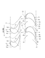
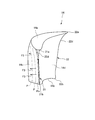
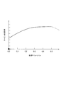
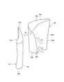
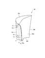
- FIG. 2 is a cross-sectional view taken along the line II-II in FIG. It is the front perspective view which looked at the stationary blade from the ventral surface side. It is the front perspective view which looked at the stationary blade from the back side. It is a meridional sectional view of a stationary blade. It is the figure which showed the relationship between the retreat rate of a retreat end part, and the turbine whole stage efficiency. It is the longitudinal cross-sectional view which selected a part of blade cascade structure in the conventional gas turbine.
- FIG. 8 is a cross-sectional view taken along arrow VIII-VIII in FIG. 7.
- a rotor 12 is rotatably supported in a casing 11 of the gas turbine 1. Furthermore, in the casing 11, a plurality of moving blades 13 and stationary blades 14 are arranged in an annular shape around the rotor 12.
- the rotor blades 13 are supported on the outer peripheral surface of the rotor 12 so as to extend in the radial direction, and are arranged at regular intervals in the circumferential direction. That is, the hub surface 13b that is the radially inner end surface of the rotor blade 13 is supported by the outer peripheral surface of the rotor 12, while the tip surface 13a that is the radially outer end surface of the rotor blade 13 is the inner peripheral surface 11a of the casing 11. Is spaced radially inward.
- a tip clearance (gap) 15 having a predetermined gap amount in the radial direction is formed between the inner peripheral surface 11 a of the casing 11 and the tip surface 13 a of the rotor blade 13. That is, a shroud for filling the chip clearance 15 is not attached to the chip surface 13a.
- the stationary blades 14 are supported on the inner peripheral surface 11a of the casing 11 so as to extend in the radial direction, and are arranged at regular intervals in the circumferential direction. That is, the tip surface 14 a serving as the radially outer end surface of the stationary blade 14 is supported by the inner peripheral surface 11 a of the casing 11, while the hub surface 14 b serving as the radially inner end surface of the stationary blade 14 is the outer peripheral surface of the rotor 12. Is spaced radially outward.
- the moving blades 13 and the stationary blades 14 are alternately arranged in the axial direction, thereby forming a cascade structure composed of a plurality of stages.
- a combustion gas (working fluid) G is supplied from the axial direction between the inner peripheral surface 11 a of the casing 11 and the outer peripheral surface of the rotor 12.
- the combustion gas G flows from the upstream side, which is upstream in the gas flow direction, toward the downstream side, which is downstream in the gas flow direction, so that the moving blades 13 and the stationary blades 14 constituting each stage are moved to the upstream side. Passes in order toward the rear side.
- the rotor blades 13 and the stationary blades 14 have shapes (blade shapes) viewed from the outside in the radial direction that are both curved in the circumferential direction.
- the rotor blade 13 is curved so as to be convex toward the downstream side in the rotational direction of the rotor 12, and the convex shape is formed on the side surfaces provided on both sides in the circumferential direction.
- the formed surface is a back surface 13c that becomes a negative pressure surface
- the concave surface is an abdominal surface 13d that becomes a positive pressure surface.
- the stationary blade 14 is curved so as to be convex toward the upstream side in the rotational direction of the rotor 12, and is convex among the side surfaces provided on both sides in the circumferential direction.
- a back surface 14c that is a negative pressure surface
- a concave surface is an abdominal surface 14d that is a positive pressure surface.
- the leading edge 21 and the trailing edge 22 are formed on the stationary blade 14.
- the front edge 21 is a vertical edge disposed on the upstream side of the stationary blade 14 and forms a top where the front end of the back surface 14c and the front end of the abdominal surface 14d intersect, and the front end of the tip surface 14a and the hub It connects between the front end of the surface 14b.
- the rear edge 22 is a vertical edge disposed on the downstream side of the stationary blade 14 and forms a top portion where the rear end portion of the back surface 14c and the rear end portion of the abdominal surface 14d intersect with each other. The rear end portion is connected to the rear end portion of the hub surface 14b.
- the secondary flow F4 caused by the leakage flow F2 of the combustion gas G leaked from the tip clearance 15 (see FIGS. 10 and 11).
- the radially outer portion of the front edge 21 is retracted toward the downstream side in the axial direction.
- FIG. 5 shows a meridional section of the stationary blade 14.
- This meridional section refers to a line (camber line) connecting a middle point in the blade thickness direction between the back surface 14c and the abdominal surface 14d. It is a longitudinal section of the stationary blade 14 when penetrating in the height direction (radial direction).
- the front edge 21 connects the front end portion of the chip surface 14a and the front end portion of the hub surface 14b, and is connected to (coincides with) the front end portion of the chip surface 14a.
- Part 21a and a radially inner end 21b connected to (matching with) the front end of hub surface 14b.
- a retreat starting point 21c is set at an intermediate portion between the radially outer end 21a and the radially inner end 21b, and among the front edges 21, from the retreat starting point 21c to the radially outer end 21a. This portion constitutes the leading edge curved portion 21d.
- the rear edge 22 connects the rear end portion of the chip surface 14a and the rear end portion of the hub surface 14b, and is connected to (coincides with) the rear end portion of the chip surface 14a in the radially outer end portion. 22a and a radially inner end 22b connected (coincident with) the rear end of the hub surface 14b. Further, a retreat starting point 22c is set at an intermediate portion between the radially outer end 22a and the radially inner end 22b. Among the rear edges 22, the retreat starting point 22c to the radially outer end 22a. This portion constitutes the trailing edge curved portion 22d.
- the axial distance between the radially inner end 21b and the radially inner end 22b is divided into two equal parts, and a straight line extending in the radial direction (blade height direction) is defined as the axial center line O. Then, the axial distance from the axial center line O to the radially inner end 21b is Lo, and the axial distance from the axial center line O to the radially outer end 21a is L. As a result, the retraction rate of the radially outer end portion 21a (the front end portion of the chip surface 14a) with respect to the radially inner end portion 21b is (Lo-L) / Lo.
- the receding rate (Lo-L) / Lo is set in a range of 0 ⁇ (Lo ⁇ L) /Lo ⁇ 0.5.
- the leading edge curved portion 21d becomes a curve that is convex toward the upstream side in the axial direction.
- the leading edge of the stationary blade connecting between the retreat start point 21c and the radially inner end 21b is linear in FIG. 5, but is not limited thereto, and is concave toward the upstream side in the axial direction. It may be a leading edge curved portion.
- the radial height H of the receding start point 21c is the radial height from the radial inner end 21b, and the radial height Ho of the radial outer end 21a is from the radial inner end 21b. It is the height in the radial direction.
- the radial height H of the retreat starting point 21c is set in a range of 0 ⁇ H ⁇ 0.8Ho.
- the angle formed by the tangential direction at the radially outer end 21a of the leading edge curved portion 21d and the radial direction is defined as ⁇ .
- the angle ⁇ is set in a range of 0 ° ⁇ ⁇ 45 °. Note that the shape (fillet) of the connecting portion between the stationary blade and the casing is not considered.
- the radially outer end 22a is retracted toward the downstream side in the axial direction, so that the trailing edge curved portion 22d becomes a curve that is convex toward the upstream side in the axial direction. Yes.
- the trailing edge curved portion 22d is formed on the trailing edge 22
- at least the radially outer end portion 22a only needs to recede toward the downstream side in the axial direction from the radially inner end portion 22b.
- the backward starting point 22c is set at the same position as the backward starting point 21c in the radial direction. That is, the radial height from the radially inner end 21b at the retreat start point 22c is H.
- the main flow F1 of the combustion gas G flows toward the rotor blade 13
- the main flow F1 of the combustion gas G flows from the side of the abdominal surface 13d to the vicinity of the front edge, and then flows along the back surface 13c and the abdominal surface 13d.
- the blade shape is convex toward the downstream side in the rotational direction, and the leading edge is disposed downstream of the trailing edge in the rotational direction.
- the rotor blades 13 are caused to flow toward the upstream side in the rotational direction while flowing from the front edge side toward the rear edge side.
- the main flow F1 of the combustion gas G is changed in the flow direction by the moving blade 13 and gives a force in the rotating direction to the moving blade 13.
- the main flow F1 of the combustion gas G flows toward the stationary blade 14
- the main flow F1 of the combustion gas G flows from the abdominal surface 14d side to the vicinity of the front edge 21, and then flows along the back surface 14c and the abdominal surface 14d.
- the blade shape has a convex shape toward the upstream side in the rotation direction, and the rear edge 22 is disposed downstream in the rotation direction from the front edge 21.
- F1 is caused to flow toward the downstream side in the rotational direction while being caused to flow from the front edge 21 side toward the rear edge 22 side by the stationary blade 14.
- the main flow F1 of the combustion gas G is rectified by the stationary blade 14 and the flow direction is changed.
- the main flow F1 of the combustion gas G flows into the moving blade 13, as described above, the main flow F1 of the combustion gas G flows from the abdominal surface 13d side, so that the main flow of fuel flowing along the surface of the moving blade 13 In the pressure of F1, the pressure on the abdominal surface 13d side becomes higher than the pressure on the back surface 13c side. Further, since the moving blade 13 has the tip clearance 15, a part of the main flow F1 of the combustion gas G flowing on the abdominal surface 13d side is caused by the pressure difference between the pressure on the back surface 13c side and the pressure on the abdominal surface 13d side. Flows from the side of the abdominal surface 13d where the pressure is high to the side of the back surface 13c where the pressure is low via the chip clearance 15.
- the leakage flow F2 which is the flow of the combustion gas G leaking from the tip clearance 15, flows into the downstream stationary blade 14 while going downstream in the rotational direction.
- the leakage flow F2 of the combustion gas G flows into the stationary blade 14
- the leakage flow F2 of the combustion gas G flows from the back surface 14c side in the vicinity of the radially outer end 21a of the front edge 21, that is, the tip. It flows toward the vicinity of the front end of the surface 14a.
- the stagnation line Po in the vicinity where the leakage flow F2 collides tends to be inclined toward the back surface 14c because the leakage flow F2 of the combustion gas G slightly collides with the back surface 14c from the front edge 21 and collides. .
- the radially outer end 21a which is a portion where the leakage flow F2 of the combustion gas G collides, is retracted axially downstream from the retreat starting point 21c.
- the leading edge curved portion 21d connecting the retracted radially outer end 21a and the retracting start point 21c is convex toward the upstream side in the axial direction.
- the portion where the leakage flow F2 of the combustion gas G collides with the stationary blade 14 can be brought close to the portion where the main flow F1 of the combustion gas G collides with the stationary blade 14, so that the stagnation line Po is set in the radial direction (blade height). Can be formed substantially linearly.
- the pressure of the combustion gas G flowing along the back surface 14c of the stationary blade 14 becomes substantially equal in the radial direction, and the isobaric line P indicating the pressure level difference of the combustion gas G is also almost in the radial direction. It is formed linearly.
- the branch flow F3 that branches from the vicinity of the front edge curved portion 21d to the back surface 14c side is along the back surface 14c. Even when flowing from the front edge 21 side toward the rear edge 22 side, there is no secondary flow F4 that is a strong flow toward the radially inner side on the back surface 14c.
- the distance (distance in the axial direction) becomes long, and the combustion gas G easily comes into contact with the inner peripheral surface 11a between them.
- the low speed region of the combustion gas G is formed along the inner peripheral surface 11a corresponding to the portion where the interstage distance is increased, and there is a possibility that the turbine efficiency is reduced.
- the retracting rate (Lo-L) / L of the radially outer end 21a is set in a range of 0 ⁇ (Lo ⁇ L) /L ⁇ 0.5.
- the retreat rate (Lo-L) / L is set to 0 ⁇ (Lo-L).
- the overall turbine efficiency can be improved as compared with a conventional gas turbine including a stationary blade 50 that does not have the leading edge curved portion 21d.
- the turbine full-stage efficiency in the gas turbine 1 according to the present invention is indicated by a solid line
- the turbine full-stage efficiency in a conventional gas turbine is indicated by ⁇ .
- the stationary blade 14 by setting the radial height H of the receding start point 21c in the range of 0 ⁇ H ⁇ 0.8Ho, the combustion gas is generated near the leading edge curved portion 21d. Since the leakage flow F2 of G easily collides, the generation of the secondary flow F4 due to the leakage flow F2 can be suppressed.
- the angle ⁇ at the radially outer end 21a of the leading edge curved portion 21d becomes a large angle exceeding 45 °, the space between the leading edge curved portion 21d and the inner peripheral surface 11a of the casing 11 is increased. (Gap) becomes very narrow. As a result, the combustion gas G stagnates in the space, which may cause a decrease in turbine efficiency.
- the angle ⁇ is set in a range of 0 ° ⁇ ⁇ 45 °, so that the space between the leading edge curved portion 21d and the inner peripheral surface 11a of the casing 11 is set. Since the space at is not narrowed, a decrease in turbine efficiency can be suppressed.
- the shaft starts from the retreat starting point 21c set at the radially outer end 21a of the front edge 21 at the intermediate portion in the height direction of the front edge 21.
- the front edge curved portion 21d connecting the radially outer end portion 21a and the retreat start point 21c is convex toward the upstream side in the axial direction.
Landscapes
- Engineering & Computer Science (AREA)
- Mechanical Engineering (AREA)
- General Engineering & Computer Science (AREA)
- Turbine Rotor Nozzle Sealing (AREA)
Abstract
ロータ(12)を回転可能に支持するケーシング(11)の内周面(11a)に設けられる静翼(14)であって、ケーシング(11)の内周面(11a)に支持されるチップ面(14a)と、ロータ(12)の外周面と径方向において対向するハブ面(14b)とを繋ぐ前縁(21)を備え、前縁(21)は、ハブ面(14b)と接続する径方向内側端部(21b)と、径方向内側端部(21b)から所定の径方向高さ(H)に設定された後退起点(21c)と、チップ面(14a)と接続すると共に後退起点(21c)よりも軸方向下流側に向けて後退した径方向外側端部(21a)と、径方向外側端部(21a)と後退起点(21c)との間を、軸方向上流側に向けて凸状をなすように結ぶ前縁湾曲部(21d)とを有する。
Description
本発明は、圧力損失を抑制するようにしたタービン静翼に関する。
従来から、流体の運動エネルギを回転エネルギに変えることによって動力を得るものとして、例えば、ガスタービンが周知となっている。このようなガスタービンにおいては、タービン効率の向上を図ることが重要な課題となっており、タービン効率の向上を図るためには、動翼や静翼に発生する圧力損失を低減させることが最も効果的とされている。
そこで、特許文献1には、圧力損失の抑制を図ることを目的としたタービン翼が開示されている。
この特許文献1に開示されたタービン翼は、動翼を対象としているが、タービン効率の向上を図る際には、動翼に発生する圧力損失だけでなく、静翼に発生する圧力損失についても、何らかの対策を採る必要がある。
ここで、ガスタービンに設置される動翼の中には、動翼のチップ面と、固定側となるケーシングとの間に、隙間を有するものがあり、このような隙間は、チップクリアランスと称されている。そして、チップクリアランスが設けられていると、当該チップクリアランスから燃焼ガスが漏れてしまい、その動翼の後段(次段)に位置する静翼においては、圧力損失が発生するおそれがある。
以下、静翼におけるチップクリアランスに起因した圧力損失について、図7乃至図11を用いて具体的に説明する。
先ず、図7に示すように、動翼13のチップ面13aには、シュラウド(図示省略)が設けられていない。このため、ケーシング11の内周面11aと動翼13のチップ面13aとの間には、隙間となるチップクリアランス15が形成されている。このように、チップクリアランス15を設置すると、当該チップクリアランス15から漏れた燃焼ガスGが、その動翼13の後段に位置する静翼50に向けて流れる場合があり、これにより、静翼50に大きな圧力損失が発生するおそれがある。
詳細に説明すると、図7乃至図9に示すように、燃焼ガスGの主流F1は、動翼13の背面13c及び腹面13dに沿って流れた後、当該動翼13の後段に位置する静翼50に向けて流れ込む。そして、静翼50に流れ込んだ燃焼ガスGの主流F1は、静翼50の背面50c及び腹面50dに沿って流れる。一方、チップクリアランス15から漏れた燃焼ガスGの漏れ流れF2は、主流F1の流入角度とは異なる流入角度で静翼50に流れ込む。
即ち、動翼13に沿って流れる燃焼ガスGの主流F1においては、背面13c側の圧力と腹面13d側の圧力との間で圧力差があり、背面13c側の圧力よりも腹面13d側の圧力の方が高くなっている。これにより、腹面13d側を流れる燃焼ガスGの主流F1における一部は、漏れ流れF2として、チップクリアランス15を通過して背面13c側に流れ込む。このとき、漏れ流れF2は、主流F1の流れ方向と交差する方向に流れる。
更に、図10及び図11に示すように、燃焼ガスGの主流F1が静翼50に流れ込んだ場合には、その主流F1は、静翼50の前縁50e付近に衝突した後、背面50c側と腹面50d側とに分流して、分岐流れF3となる。これにより、静翼50の前縁50e付近には、よどみ線Poが発生する。このよどみ線Poは、背面50c側に向けて流れる燃焼ガスGの分岐流れF3と、腹面50d側に向けて流れる燃焼ガスGの分岐流れF3との境界となるものであって、静翼50の表面の中で最も圧力が高くなる領域となっている。
このように、静翼50に流れ込んだ燃焼ガスGの主流F1は、よどみ線Poを境界にして、背面50c側と腹面50d側とに分かれて流れるため、そのよどみ線Poは、翼高さ方向(径方向)に直線的に延びるように形成されることが好ましい。しかしながら、チップクリアランス15から漏れた燃焼ガスGの漏れ流れF2が発生した場合には、よどみ線Poの発生位置は変化する。
つまり、燃焼ガスGの漏れ流れF2は、静翼50の前縁50e付近における背面50c寄りの位置から、当該静翼50に流れ込む。これにより、前縁50eのチップ面50a付近においては、よどみ線Poが背面50c側に向けてずれることになる。即ち、静翼50に発生するよどみ線Poにおいては、漏れ流れF2の流入によって、チップ面50a付近のみが背面50c側に移動する。
よって、静翼50の背面50cに沿って流れる燃焼ガスGの圧力分布は、よどみ線Poの傾斜に倣って変化し、その圧力高低差を示す等圧力線Pは、チップ面50aに近づくに従って、背面50c側に向けて歪んでしまう。これにより、静翼50の背面50cにおいては、等圧力線Pの歪んだ部分と直交し、且つ、チップ面50a側からハブ面50b側に向かう流れが誘起される。
この結果、背面50cに沿って流れる燃焼ガスGの分岐流れF3は、前縁50eから後縁50fに向けて、翼高さ方向の位置を殆ど変えることなく流れることになるが、分岐流れF3の中でも、等圧力線Pの歪んだ部分を通る分岐流れF3は、2次流れF4として、前縁50eから後縁50fに向かいつつ、チップ面50a側からハブ面50b側に向って流れることになる。このような、燃焼ガスGの2次流れF4は、径方向内側に向かう強い流れとなっている。これにより、静翼50の背面50cにおいては、圧力損失となる2次流れ損失が発生してしまうため、この2次流れ損失によって、タービン効率が低下するおそれがある。
従って、本発明は上記課題を解決するものであって、背面に沿って流れる2次流れの発生を抑えて、その2次流れの発生に伴う2次流れ損失を低減させることにより、タービン効率の向上を図ることができるタービン静翼及びこれを備えたタービンを提供することを目的とする。
上記課題を解決する第1の発明に係るタービン静翼は、
ロータを回転可能に支持するケーシングの内周面に、周方向において所定の間隔で設けられるタービン静翼であって、
前記ケーシングの内周面に支持され、径方向外側端面となるチップ面と、
前記ロータの外周面と径方向において対向し、径方向内側端面となるハブ面と、
前記チップ面と前記ハブ面とを径方向において繋ぎ、上流側に配置される縦縁となる前縁と、
前記チップ面と前記ハブ面とを径方向において繋ぎ、下流側に配置される縦縁となる後縁とを備え、
前記前縁は、
前記ハブ面と接続する径方向内側端部と、
前記径方向内側端部から所定の径方向高さに設定される後退起点と、
前記チップ面と接続すると共に、前記後退起点よりも軸方向下流側に向けて後退した径方向外側端部と、
前記後退起点と前記径方向外側端部との間を、軸方向上流側に向けて凸状をなすように結ぶ前縁湾曲部とを有する
ことを特徴とする。
ロータを回転可能に支持するケーシングの内周面に、周方向において所定の間隔で設けられるタービン静翼であって、
前記ケーシングの内周面に支持され、径方向外側端面となるチップ面と、
前記ロータの外周面と径方向において対向し、径方向内側端面となるハブ面と、
前記チップ面と前記ハブ面とを径方向において繋ぎ、上流側に配置される縦縁となる前縁と、
前記チップ面と前記ハブ面とを径方向において繋ぎ、下流側に配置される縦縁となる後縁とを備え、
前記前縁は、
前記ハブ面と接続する径方向内側端部と、
前記径方向内側端部から所定の径方向高さに設定される後退起点と、
前記チップ面と接続すると共に、前記後退起点よりも軸方向下流側に向けて後退した径方向外側端部と、
前記後退起点と前記径方向外側端部との間を、軸方向上流側に向けて凸状をなすように結ぶ前縁湾曲部とを有する
ことを特徴とする。
上記課題を解決する第2の発明に係るタービン静翼は、
前記後退起点と前記径方向内側端部との間を、前記軸方向上流側に向けて凹状もしくは直線状をなすように結ばれる
ことを特徴とする。
前記後退起点と前記径方向内側端部との間を、前記軸方向上流側に向けて凹状もしくは直線状をなすように結ばれる
ことを特徴とする。
上記課題を解決する第3の発明に係るタービン静翼は、
前記後縁は、前記ハブ面と接続する径方向内側端部を有し、
前記前縁の径方向内側端部と前記後縁の径方向内側端部との間の軸方向距離を2等分し、且つ、径方向に延在する軸方向中心線から、前記前縁の径方向内側端部までの軸方向距離を、Loとし、
前記軸方向中心線から、前記前縁の径方向外側端部までの軸方向距離を、Lとし、
前記前縁における径方向外側端部の後退率を、(Lo-L)/Loとするときに、
後退率(Lo-L)/Loの範囲は、0≦(Lo-L)/Lo≦0.5となる
ことを特徴とする。
前記後縁は、前記ハブ面と接続する径方向内側端部を有し、
前記前縁の径方向内側端部と前記後縁の径方向内側端部との間の軸方向距離を2等分し、且つ、径方向に延在する軸方向中心線から、前記前縁の径方向内側端部までの軸方向距離を、Loとし、
前記軸方向中心線から、前記前縁の径方向外側端部までの軸方向距離を、Lとし、
前記前縁における径方向外側端部の後退率を、(Lo-L)/Loとするときに、
後退率(Lo-L)/Loの範囲は、0≦(Lo-L)/Lo≦0.5となる
ことを特徴とする。
上記課題を解決する第4の発明に係るタービン静翼は、
前記前縁の径方向内側端部から前記後退起点までの径方向高さを、Hとし、
前記前縁の径方向内側端部から前記前縁の径方向外側端部までの径方向高さを、Hoとするときに、
径方向高さHの範囲は、0<H≦0.8Hoとなる
ことを特徴とする。
前記前縁の径方向内側端部から前記後退起点までの径方向高さを、Hとし、
前記前縁の径方向内側端部から前記前縁の径方向外側端部までの径方向高さを、Hoとするときに、
径方向高さHの範囲は、0<H≦0.8Hoとなる
ことを特徴とする。
上記課題を解決する第5の発明に係るタービン静翼は、
前記前縁の径方向外側端部における接線方向と、径方向とがなす角度を、θとするときに、
角度θの範囲は、0°<θ≦45°となる
ことを特徴とする。
前記前縁の径方向外側端部における接線方向と、径方向とがなす角度を、θとするときに、
角度θの範囲は、0°<θ≦45°となる
ことを特徴とする。
上記課題を解決する第6の発明に係るタービン静翼は、
前記後縁は、前記チップ面と接続する径方向外側端部を有し、
前記後縁の径方向外側端部は、前記後縁の径方向内側端部よりも軸方向下流側に向けて後退している
ことを特徴とする。
前記後縁は、前記チップ面と接続する径方向外側端部を有し、
前記後縁の径方向外側端部は、前記後縁の径方向内側端部よりも軸方向下流側に向けて後退している
ことを特徴とする。
上記課題を解決する第7の発明に係るタービンは、
ロータを回転可能に支持するケーシングの内周面に周方向において所定の間隔で設けられる静翼と、前記ロータの外周面に周方向において所定の間隔で設けられる動翼とを、軸方向において交互に配置するタービンにおいて、
前記タービン静翼は、
前記ケーシングの内周面との間でチップクリアランスを有する前記動翼の後段に配置される
ことを特徴とする。
ロータを回転可能に支持するケーシングの内周面に周方向において所定の間隔で設けられる静翼と、前記ロータの外周面に周方向において所定の間隔で設けられる動翼とを、軸方向において交互に配置するタービンにおいて、
前記タービン静翼は、
前記ケーシングの内周面との間でチップクリアランスを有する前記動翼の後段に配置される
ことを特徴とする。
従って、本発明に係るタービン静翼及びこれを備えたタービンによれば、前縁の径方向外側端部を、当該前縁における高さ方向中間部に設定した後退起点よりも軸方向下流側に向けて後退させると共に、その径方向外側端部と後退起点とを結ぶ前縁湾曲部を、軸方向上流側に向けて凸状としている。また、後退起点と前記径方向内側端部との間は軸方向上流側に向けて凹状もしくは直線状をなすように静翼前縁を構成してもよい。これにより、背面に沿って流れる2次流れの発生を抑えることができるので、その2次流れの発生に伴う2次流れ損失を低減させることができる。この結果、タービン効率の向上を図ることができる。なお、前縁の径方向内側端部を、当該後退起点よりも軸方向下流側に向けて後退させることが望ましい。
以下、本発明に係るタービン静翼及びこれを備えたタービンについて、図面を用いて詳細に説明する。
図1に示すように、ガスタービン1のケーシング11内には、ロータ12が回転可能に支持されている。更に、ケーシング11内には、複数枚の動翼13及び静翼14が、ロータ12を中心として、円環状に配置されている。
動翼13は、ロータ12の外周面に、径方向に向けて延びるように支持されており、周方向において一定の間隔で配置されている。つまり、動翼13の径方向内側端面となるハブ面13bは、ロータ12の外周面に支持される一方、動翼13の径方向外側端面となるチップ面13aは、ケーシング11の内周面11aから径方向内側に離間している。
このとき、ケーシング11の内周面11aと動翼13のチップ面13aとの間には、径方向において所定の隙間量となるチップクリアランス(隙間)15が形成されている。即ち、チップ面13aには、そのチップクリアランス15を埋めるためのシュラウドが取り付けられていない。
一方、静翼14は、ケーシング11の内周面11aに、径方向に向けて延びるように支持されており、周方向において一定の間隔で配置されている。つまり、静翼14の径方向外側端面となるチップ面14aは、ケーシング11の内周面11aに支持される一方、静翼14の径方向内側端面となるハブ面14bは、ロータ12の外周面から径方向外側に離間している。
また、動翼13と静翼14とは、軸方向において交互に配置されることにより、複数の段からなる翼列構造をなしている。そして、ケーシング11の内周面11aとロータ12の外周面との間には、燃焼ガス(作動流体)Gが軸方向から供給されるようになっている。これにより、燃焼ガスGは、ガス流れ方向上流側となる前段側から、ガス流れ方向下流側となる後段側に向けて流れることにより、各段を構成する動翼13及び静翼14を前段側から後段側に向けて順に通過することになる。
更に、動翼13及び静翼14は、径方向外側から見た形状(翼形状)が、共に周方向において湾曲した形状となっている。具体的に、図2に示すように、動翼13は、ロータ12の回転方向下流側に向かって凸状をなすように湾曲しており、周方向両側に設けられる側面にうち、凸状をなす面が、負圧面となる背面13cとなっており、凹状をなす面が、正圧面となる腹面13dとなっている。一方、図2乃至図4に示すように、静翼14は、ロータ12の回転方向上流側に向かって凸状をなすように湾曲しており、周方向両側に設けられる側面のうち、凸状をなす面が、負圧面となる背面14cとなっており、凹状をなす面が、正圧面となる腹面14dとなっている。
そして、静翼14には、前縁21及び後縁22が形成されている。前縁21は、静翼14における上流側に配置される縦縁であって、背面14cの前端部と腹面14dの前端部とが交差する頂部を形成すると共に、チップ面14aの前端部とハブ面14bの前端部との間を繋いでいる。一方、後縁22は、静翼14における下流側に配置される縦縁であって、背面14cの後端部と腹面14dの後端部とが交差する頂部を形成すると共に、チップ面14aの後端部とハブ面14bの後端部との間を繋いでいる。
ここで、チップクリアランス15を有する動翼13の後段に位置する静翼14においては、そのチップクリアランス15から漏れた燃焼ガスGの漏れ流れF2に起因した2次流れF4(図10及び図11参照)の発生を抑えるため、前縁21における径方向外側部分を軸方向下流側に向けて後退させるようにしている。
そこで、以下に、上記2次流れF4に対応した静翼14の形状について、図5を用いて詳細に説明する。なお、図5は、静翼14の子午断面を示しているが、この子午断面とは、背面14cと腹面14dとの間における翼厚さ方向中間点を結んだ線(キャンバーライン)を、翼高さ方向(径方向)に貫いたときの静翼14の縦断面となっている。
図5に示すように、前縁21は、チップ面14aの前端部とハブ面14bの前端部との間を繋いでおり、チップ面14aの前端部と接続する(一致する)径方向外側端部21aと、ハブ面14bの前端部と接続する(一致する)径方向内側端部21bとを有している。更に、径方向外側端部21aと径方向内側端部21bとの間の中間部には、後退起点21cが設定されており、前縁21の中でも、後退起点21cから径方向外側端部21aまでの部分は、前縁湾曲部21dを構成している。
一方、後縁22は、チップ面14aの後端部とハブ面14bの後端部との間を繋いでおり、そのチップ面14aの後端部と接続する(一致する)径方向外側端部22aと、そのハブ面14bの後端部と接続する(一致する)径方向内側端部22bとを有している。更に、径方向外側端部22aと径方向内側端部22bとの間の中間部には、後退起点22cが設定されており、後縁22の中でも、後退起点22cから径方向外側端部22aまでの部分は、後縁湾曲部22dを構成している。
そして、径方向内側端部21bと径方向内側端部22bとの間の軸方向距離を2等分し、且つ、径方向(翼高さ方向)に延在する直線を、軸方向中心線Oとすると、軸方向中心線Oから径方向内側端部21bまでの軸方向距離は、Loとなり、軸方向中心線Oから径方向外側端部21aまでの軸方向距離は、Lとなる。これにより、径方向外側端部21a(チップ面14aの前端部)の径方向内側端部21bに対する後退率は、(Lo-L)/Loとなる。このとき、後退率(Lo-L)/Loは、0≦(Lo-L)/Lo≦0.5の範囲に設定されている。このように、径方向外側端部21aを、軸方向下流側に向けて後退させることにより、前縁湾曲部21dは、軸方向上流側に向けて凸状をなす曲線となる。一方、後退起点21cと径方向内側端部21bとの間を結ぶ静翼前縁は、図5中では直線状であるが、これに限るものではなく、軸方向上流側に向けて凹状となった前縁湾曲部となっていても良い。これにより、背面に沿って流れる2次流れの発生を抑えることができるので、その2次流れの発生に伴う2次流れ損失を低減させることができる。この結果、タービン効率の向上を図ることができる。
また、後退起点21cの径方向高さHは、径方向内側端部21bからの径方向高さとなっており、径方向外側端部21aの径方向高さHoは、径方向内側端部21bからの径方向高さとなっている。このとき、後退起点21cの径方向高さHは、0<H≦0.8Hoの範囲に設定されている。
更に、前縁湾曲部21dの径方向外側端部21aにおける接線方向と、径方向とがなす角度をθとする。このとき、角度θは、0°<θ≦45°の範囲に設定されている。なお、静翼とケーシングとの接続部の形状(フィレット)は考慮しない。
なお、後縁22においても、径方向外側端部22aを、軸方向下流側に向けて後退させることにより、後縁湾曲部22dが、軸方向上流側に向けて凸状をなす曲線となっている。このとき、後縁22に後縁湾曲部22dを形成する場合には、少なくとも、径方向外側端部22aが径方向内側端部22bよりも軸方向下流側に向けて後退していれば良い。このように、前縁21に前縁湾曲部21dを形成すると共に、後縁22に後縁湾曲部22dを形成することにより、静翼14の断面積を維持することができるので、当該静翼14の剛性を保つことができる。但し、後退起点22cは、径方向において、後退起点21cと同じ位置に設定されている。即ち、後退起点22cにおける径方向内側端部21bからの径方向高さは、Hとなっている。
次に、複数段の動翼13及び静翼14を備えたガスタービン1の作用について、図1乃至図4を用いて詳細に説明する
先ず、図1及び図2に示すように、ガスタービン1の運転が開始されると、ロータ12の回転に伴って動翼13が回転する。これにより、軸方向上流側から供給された燃焼ガスGは、動翼13及び静翼14を順次通過しながら、前段側(上流側)から後段側(下流側)に向けて流される。
即ち、燃焼ガスGの主流F1が動翼13に向けて流されると、当該燃焼ガスGの主流F1は、腹面13d側から前縁付近に流れ込んだ後、背面13c及び腹面13dに沿って流れる。このとき、動翼13においては、翼形状が回転方向下流側に向けて凸状をなすと共に、前縁が後縁よりも回転方向下流側に配置されているため、燃焼ガスGの主流F1は、動翼13によって、その前縁側から後縁側に向けて流されつつ、回転方向上流側に向けて流される。これにより、燃焼ガスGの主流F1は、動翼13によって、流れの向きが変えられると共に、動翼13に対して回転方向への力を与える。
言い換えれば、動翼13は、燃焼ガスGの流れの向きを変更させる際に、当該燃焼ガスGから受ける反作用によって、回転方向への力が付与される。これにより、動翼13を支持するロータ12は、回転する。
また、燃焼ガスGの主流F1が静翼14に向けて流されると、当該燃焼ガスGの主流F1は、腹面14d側から前縁21付近に流れ込んだ後、背面14c及び腹面14dに沿って流れる。このとき、静翼14においては、翼形状が回転方向上流側に向けて凸状をなすと共に、後縁22が前縁21よりも回転方向下流側に配置されているため、燃焼ガスGの主流F1は、静翼14によって、前縁21側から後縁22側に向けて流されつつ、回転方向下流側に向けて流される。これにより、燃焼ガスGの主流F1は、静翼14によって、整流化されると共に、流れの向きが変えられる。
ここで、燃焼ガスGの主流F1が動翼13に流れ込む際には、上述したように、当該燃焼ガスGの主流F1が腹面13d側から流れ込むため、動翼13の表面に沿って流れる燃主流F1の圧力においては、背面13c側の圧力よりも、腹面13d側の圧力が高くなる。また、動翼13がチップクリアランス15を有しているため、腹面13d側を流れる燃焼ガスGの主流F1における一部は、背面13c側の圧力と腹面13d側の圧力との圧力差によって、圧力が高い腹面13d側から、チップクリアランス15を介して、圧力が低い背面13c側に流れ込む。
つまり、チップクリアランス15から漏れた燃焼ガスGの流れとなる、漏れ流れF2は、回転方向下流側に向かいつつ、後段の静翼14に流れ込む。この結果、燃焼ガスGの漏れ流れF2が静翼14に流れ込む際には、当該燃焼ガスGの漏れ流れF2が、背面14c側から、前縁21の径方向外側端部21a付近、即ち、チップ面14aの前端部付近に向けて流れ込む。
一方、燃焼ガスGの主流F1が静翼14に流れ込む際には、当該燃焼ガスGの主流F1は、腹面14d側から、前縁21付近に向けて流れ込んだ後、背面14c側と腹面14d側とに分かれて流れる。これにより、図3及び図4に示すように、双方向の流れの分岐部分となる前縁21上には、燃焼ガスGの圧力が最も高くなる領域として、よどみ線(図中、網掛け範囲)Poが発生する。このとき、燃焼ガスGの漏れ流れF2が、前縁21よりも若干背面14c側にずれて衝突する分、その漏れ流れF2が衝突する付近のよどみ線Poは、背面14c側に傾く傾向にある。
これに対して、本発明に係る静翼14においては、燃焼ガスGの漏れ流れF2が衝突する部分となる径方向外側端部21aを、後退起点21cを起点として、軸方向下流側に後退させて、その後退した径方向外側端部21aと後退起点21cとを結ぶ前縁湾曲部21dを、軸方向上流側に向けて凸状としている。このように、前縁21の中でも、前縁湾曲部21dを後退させることにより、燃焼ガスGの漏れ流れF2が静翼14に衝突する部分を、腹面14d側にずらすことができる。
よって、燃焼ガスGの漏れ流れF2が静翼14に衝突する部分を、燃焼ガスGの主流F1が静翼14に衝突する部分に近づけることができるので、よどみ線Poを、径方向(翼高さ方向)に向けて、ほぼ直線的に形成することができる。この結果、静翼14の背面14cに沿って流れる燃焼ガスGの圧力は、径方向においてほぼ等しくなり、燃焼ガスGの圧力高低差を示す等圧力線Pについても、径方向に向けて、ほぼ直線的に形成される。
従って、前縁21付近から背面14c側及び腹面14d側に分岐する、燃焼ガスGの分岐流れF3の中でも、前縁湾曲部21d付近から背面14c側に分岐する分岐流れF3は、背面14cに沿って前縁21側から後縁22側に向けて流れる場合でも、背面14c上において、径方向内側に向かう強い流れとなる2次流れF4になることはない。
このとき、前縁21に前縁湾曲部21dを形成してしまうと、その前縁湾曲部21dを有する静翼14と、当該静翼14の前段に位置する動翼13との間における段間距離(軸方向距離)が、長くなり、それらの間における内周面11aに、燃焼ガスGが接触し易くなる。この結果、燃焼ガスGの低速領域が、段間距離が長くなった部分に対応した内周面11aに沿って形成され、タービン効率の低下を招くおそれがある。これに対して、本発明に係る静翼14においては、径方向外側端部21aの後退率(Lo-L)/Lを、0≦(Lo-L)/L≦0.5の範囲に設定することにより、静翼14と動翼13との間における段間距離が長くなることがないので、タービン効率の低下を抑制することができる。
そして、図6に示すように、前縁湾曲部21dを有する静翼14を備えた本発明に係るガスタービン1においては、後退率(Lo-L)/Lを、0≦(Lo-L)/L≦0.5の範囲に設定することにより、前縁湾曲部21dを有していない静翼50を備えた従来のガスタービンと比べて、タービン全段効率を向上させることができる。なお、図6においては、本発明に係るガスタービン1におけるタービン全段効率を、実線で示しており、従来のガスタービンにおけるタービン全段効率を、●印で示している。
また、前縁湾曲部21dの長さが短くなり過ぎると、当該前縁湾曲部21d付近に燃焼ガスGの漏れ流れF2が衝突し難くなってしまい、2次流れF4の発生防止効果が得られないおそれがある。これに対して、本発明に係る静翼14においては、後退起点21cの径方向高さHを、0<H≦0.8Hoの範囲に設定することにより、前縁湾曲部21d付近に燃焼ガスGの漏れ流れF2が衝突し易くなるため、その漏れ流れF2に起因した2次流れF4の発生を抑制することができる。
更に、前縁湾曲部21dの径方向外側端部21aにおける角度θが、45°を超えるような、大きな角度になると、その前縁湾曲部21dとケーシング11の内周面11aとの間における空間(隙間)が非常に狭くなってしまう。この結果、その空間内において、燃焼ガスGが停滞してしまうため、タービン効率の低下を招くおそれがある。これに対して、本発明に係る静翼14においては、角度θを、0°<θ≦45°の範囲に設定することにより、前縁湾曲部21dとケーシング11の内周面11aとの間における空間が狭くなることがないので、タービン効率の低下を抑制することができる。
従って、本発明に係る静翼14及びガスタービン1によれば、前縁21の径方向外側端部21aを、当該前縁21における高さ方向中間部に設定した後退起点21cを起点として、軸方向下流側に向けて後退させると共に、その径方向外側端部21aと後退起点21cとを結ぶ前縁湾曲部21dを、軸方向上流側に向けて凸状としている。これにより、背面14cに沿って流れる2次流れF4の発生を抑えることができるので、その2次流れF4の発生に伴う2次流れ損失を低減させることができる。この結果、タービン効率の向上を図ることができる。
1 ガスタービン
11 ケーシング
11a 内周面
12 ロータ
13 動翼
13a チップ面
13b ハブ面
13c 背面
13d 腹面
14 静翼
14a チップ面
14b ハブ面
14c 背面
14d 腹面
15 チップクリアランス
21 前縁
21a 径方向外側端部
21b 径方向内側端部
21c 後退起点
21d 前縁湾曲部
22 後縁
22a 径方向外側端部
22b 径方向内側端部
22c 後退起点
22d 後縁湾曲部
G 燃焼ガス
F1 主流
F2 漏れ流れ
F3 分岐流れ
F4 2次流れ
Po よどみ線
P 等圧力線
O 軸方向中心線
Lo,L 軸方向距離
Ho,H 径方向高さ
θ 角度
11 ケーシング
11a 内周面
12 ロータ
13 動翼
13a チップ面
13b ハブ面
13c 背面
13d 腹面
14 静翼
14a チップ面
14b ハブ面
14c 背面
14d 腹面
15 チップクリアランス
21 前縁
21a 径方向外側端部
21b 径方向内側端部
21c 後退起点
21d 前縁湾曲部
22 後縁
22a 径方向外側端部
22b 径方向内側端部
22c 後退起点
22d 後縁湾曲部
G 燃焼ガス
F1 主流
F2 漏れ流れ
F3 分岐流れ
F4 2次流れ
Po よどみ線
P 等圧力線
O 軸方向中心線
Lo,L 軸方向距離
Ho,H 径方向高さ
θ 角度
Claims (7)
- ロータを回転可能に支持するケーシングの内周面に、周方向において所定の間隔で設けられるタービン静翼であって、
前記ケーシングの内周面に支持され、径方向外側端面となるチップ面と、
前記ロータの外周面と径方向において対向し、径方向内側端面となるハブ面と、
前記チップ面と前記ハブ面とを径方向において繋ぎ、上流側に配置される縦縁となる前縁と、
前記チップ面と前記ハブ面とを径方向において繋ぎ、下流側に配置される縦縁となる後縁とを備え、
前記前縁は、
前記ハブ面と接続する径方向内側端部と、
前記径方向内側端部から所定の径方向高さに設定される後退起点と、
前記チップ面と接続すると共に、前記後退起点よりも軸方向下流側に向けて後退した径方向外側端部と、
前記後退起点と前記径方向外側端部との間を、軸方向上流側に向けて凸状をなすように結ぶ前縁湾曲部とを有する
ことを特徴とするタービン静翼。 - 請求項1に記載のタービン静翼において、
前記後退起点と前記径方向内側端部との間を、前記軸方向上流側に向けて凹状もしくは直線状をなすように結ばれる
ことを特徴とするタービン静翼。 - 請求項1又は2に記載のタービン静翼において、
前記後縁は、前記ハブ面と接続する径方向内側端部を有し、
前記前縁の径方向内側端部と前記後縁の径方向内側端部との間の軸方向距離を2等分し、且つ、径方向に延在する軸方向中心線から、前記前縁の径方向内側端部までの軸方向距離を、Loとし、
前記軸方向中心線から、前記前縁の径方向外側端部までの軸方向距離を、Lとし、
前記前縁における径方向外側端部の後退率を、(Lo-L)/Loとするときに、
後退率(Lo-L)/Loの範囲は、0≦(Lo-L)/Lo≦0.5となる
ことを特徴とするタービン静翼。 - 請求項1乃至3に記載のタービン静翼において、
前記前縁の径方向内側端部から前記後退起点までの径方向高さを、Hとし、
前記前縁の径方向内側端部から前記前縁の径方向外側端部までの径方向高さを、Hoとするときに、
径方向高さHの範囲は、0<H≦0.8Hoとなる
ことを特徴とするタービン静翼。 - 請求項1乃至4のいずれかに記載のタービン静翼において、
前記前縁の径方向外側端部における接線方向と、径方向とがなす角度を、θとするときに、
角度θの範囲は、0°<θ≦45°となる
ことを特徴とするタービン静翼。 - 請求項1乃至5のいずれかに記載のタービン静翼において、
前記後縁は、前記チップ面と接続する径方向外側端部を有し、
前記後縁の径方向外側端部は、前記後縁の径方向内側端部よりも軸方向下流側に向けて後退している
ことを特徴とするタービン静翼。 - ロータを回転可能に支持するケーシングの内周面に周方向において所定の間隔で設けられる静翼と、前記ロータの外周面に周方向において所定の間隔で設けられる動翼とを、軸方向において交互に配置するタービンにおいて、
請求項1乃至6のいずれかに記載された前記タービン静翼は、
前記ケーシングの内周面との間でチップクリアランスを有する前記動翼の後段に配置される
ことを特徴とするタービン。
Applications Claiming Priority (2)
| Application Number | Priority Date | Filing Date | Title |
|---|---|---|---|
| JP2016-093616 | 2016-05-09 | ||
| JP2016093616 | 2016-05-09 |
Publications (1)
| Publication Number | Publication Date |
|---|---|
| WO2017195782A1 true WO2017195782A1 (ja) | 2017-11-16 |
Family
ID=60267961
Family Applications (1)
| Application Number | Title | Priority Date | Filing Date |
|---|---|---|---|
| PCT/JP2017/017557 Ceased WO2017195782A1 (ja) | 2016-05-09 | 2017-05-09 | タービン静翼及びこれを備えたタービン |
Country Status (1)
| Country | Link |
|---|---|
| WO (1) | WO2017195782A1 (ja) |
Cited By (1)
| Publication number | Priority date | Publication date | Assignee | Title |
|---|---|---|---|---|
| WO2019187435A1 (ja) | 2018-03-30 | 2019-10-03 | 三菱重工航空エンジン株式会社 | 航空機用ガスタービン |
Citations (4)
| Publication number | Priority date | Publication date | Assignee | Title |
|---|---|---|---|---|
| JPH0681603A (ja) * | 1992-09-03 | 1994-03-22 | Hitachi Ltd | 軸流形ターボ機械の静翼構造 |
| JP2002213206A (ja) * | 2001-01-12 | 2002-07-31 | Mitsubishi Heavy Ind Ltd | ガスタービンにおける翼構造 |
| EP1612372A1 (en) * | 2004-07-01 | 2006-01-04 | Alstom Technology Ltd | Turbine blade with a cut-back at the tip or the root of the blade |
| JP2009121468A (ja) * | 2007-11-09 | 2009-06-04 | Alstom Technology Ltd | 蒸気タービン |
-
2017
- 2017-05-09 WO PCT/JP2017/017557 patent/WO2017195782A1/ja not_active Ceased
Patent Citations (4)
| Publication number | Priority date | Publication date | Assignee | Title |
|---|---|---|---|---|
| JPH0681603A (ja) * | 1992-09-03 | 1994-03-22 | Hitachi Ltd | 軸流形ターボ機械の静翼構造 |
| JP2002213206A (ja) * | 2001-01-12 | 2002-07-31 | Mitsubishi Heavy Ind Ltd | ガスタービンにおける翼構造 |
| EP1612372A1 (en) * | 2004-07-01 | 2006-01-04 | Alstom Technology Ltd | Turbine blade with a cut-back at the tip or the root of the blade |
| JP2009121468A (ja) * | 2007-11-09 | 2009-06-04 | Alstom Technology Ltd | 蒸気タービン |
Cited By (4)
| Publication number | Priority date | Publication date | Assignee | Title |
|---|---|---|---|---|
| WO2019187435A1 (ja) | 2018-03-30 | 2019-10-03 | 三菱重工航空エンジン株式会社 | 航空機用ガスタービン |
| JP2019178636A (ja) * | 2018-03-30 | 2019-10-17 | 三菱重工航空エンジン株式会社 | 航空機用ガスタービン |
| US11111820B2 (en) | 2018-03-30 | 2021-09-07 | Mitsubishi Heavy Industries Aero Engines, Ltd. | Gas turbine for aircraft |
| JP7061497B2 (ja) | 2018-03-30 | 2022-04-28 | 三菱重工航空エンジン株式会社 | 航空機用ガスタービン |
Similar Documents
| Publication | Publication Date | Title |
|---|---|---|
| JP4838733B2 (ja) | ガスタービンの翼構造 | |
| JP5603800B2 (ja) | タービン静翼、およびそれを用いた蒸気タービン設備 | |
| JP4923073B2 (ja) | 遷音速翼 | |
| JP5985351B2 (ja) | 軸流タービン | |
| JP5946707B2 (ja) | 軸流タービン動翼 | |
| JP4929193B2 (ja) | タービン翼列エンドウォール | |
| CA2682489C (en) | Wall of turbo machine and turbo machine | |
| JP6034860B2 (ja) | ターボ機械要素 | |
| US20170218773A1 (en) | Blade cascade and turbomachine | |
| US20150110617A1 (en) | Turbine airfoil including tip fillet | |
| US9011084B2 (en) | Steam turbine stator vane and steam turbine using the same | |
| JP2010156335A (ja) | 改良型タービン翼プラットフォームの輪郭に関する方法および装置 | |
| CN100353031C (zh) | 透平叶片 | |
| JP5651459B2 (ja) | タービンエンジンにおける圧縮機の動作に関するシステム及び装置 | |
| JP6153650B2 (ja) | 蒸気タービンの静止体及びこれを備えた蒸気タービン | |
| EP3064709B1 (en) | Turbine bucket platform for influencing hot gas incursion losses | |
| JP5314441B2 (ja) | 遠心型水力機械 | |
| JP6066948B2 (ja) | シュラウド、動翼体、及び回転機械 | |
| JP6518526B2 (ja) | 軸流タービン | |
| US20210040855A1 (en) | Assembly of turbine blades and corresponding article of manufacture | |
| JP7483611B2 (ja) | タービン用の制御されたフローガイド | |
| US9719355B2 (en) | Rotary machine blade having an asymmetric part-span shroud and method of making same | |
| JP2016037875A (ja) | 液体機械 | |
| JP2010169047A (ja) | 軸流タービン | |
| US10648339B2 (en) | Contouring a blade/vane cascade stage |
Legal Events
| Date | Code | Title | Description |
|---|---|---|---|
| NENP | Non-entry into the national phase |
Ref country code: DE |
|
| 121 | Ep: the epo has been informed by wipo that ep was designated in this application |
Ref document number: 17796143 Country of ref document: EP Kind code of ref document: A1 |
|
| 122 | Ep: pct application non-entry in european phase |
Ref document number: 17796143 Country of ref document: EP Kind code of ref document: A1 |
|
| NENP | Non-entry into the national phase |
Ref country code: JP |