WO2017195716A1 - Crane - Google Patents
Crane Download PDFInfo
- Publication number
- WO2017195716A1 WO2017195716A1 PCT/JP2017/017341 JP2017017341W WO2017195716A1 WO 2017195716 A1 WO2017195716 A1 WO 2017195716A1 JP 2017017341 W JP2017017341 W JP 2017017341W WO 2017195716 A1 WO2017195716 A1 WO 2017195716A1
- Authority
- WO
- WIPO (PCT)
- Prior art keywords
- hydraulic oil
- pressure reducing
- emergency
- reducing valve
- proportional pressure
- Prior art date
Links
Images


Classifications
-
- B—PERFORMING OPERATIONS; TRANSPORTING
- B66—HOISTING; LIFTING; HAULING
- B66C—CRANES; LOAD-ENGAGING ELEMENTS OR DEVICES FOR CRANES, CAPSTANS, WINCHES, OR TACKLES
- B66C13/00—Other constructional features or details
- B66C13/18—Control systems or devices
- B66C13/20—Control systems or devices for non-electric drives
-
- B—PERFORMING OPERATIONS; TRANSPORTING
- B66—HOISTING; LIFTING; HAULING
- B66C—CRANES; LOAD-ENGAGING ELEMENTS OR DEVICES FOR CRANES, CAPSTANS, WINCHES, OR TACKLES
- B66C23/00—Cranes comprising essentially a beam, boom, or triangular structure acting as a cantilever and mounted for translatory of swinging movements in vertical or horizontal planes or a combination of such movements, e.g. jib-cranes, derricks, tower cranes
- B66C23/62—Constructional features or details
- B66C23/82—Luffing gear
-
- B—PERFORMING OPERATIONS; TRANSPORTING
- B66—HOISTING; LIFTING; HAULING
- B66C—CRANES; LOAD-ENGAGING ELEMENTS OR DEVICES FOR CRANES, CAPSTANS, WINCHES, OR TACKLES
- B66C23/00—Cranes comprising essentially a beam, boom, or triangular structure acting as a cantilever and mounted for translatory of swinging movements in vertical or horizontal planes or a combination of such movements, e.g. jib-cranes, derricks, tower cranes
- B66C23/62—Constructional features or details
- B66C23/84—Slewing gear
- B66C23/86—Slewing gear hydraulically actuated
-
- F—MECHANICAL ENGINEERING; LIGHTING; HEATING; WEAPONS; BLASTING
- F15—FLUID-PRESSURE ACTUATORS; HYDRAULICS OR PNEUMATICS IN GENERAL
- F15B—SYSTEMS ACTING BY MEANS OF FLUIDS IN GENERAL; FLUID-PRESSURE ACTUATORS, e.g. SERVOMOTORS; DETAILS OF FLUID-PRESSURE SYSTEMS, NOT OTHERWISE PROVIDED FOR
- F15B11/00—Servomotor systems without provision for follow-up action; Circuits therefor
- F15B11/08—Servomotor systems without provision for follow-up action; Circuits therefor with only one servomotor
-
- F—MECHANICAL ENGINEERING; LIGHTING; HEATING; WEAPONS; BLASTING
- F15—FLUID-PRESSURE ACTUATORS; HYDRAULICS OR PNEUMATICS IN GENERAL
- F15B—SYSTEMS ACTING BY MEANS OF FLUIDS IN GENERAL; FLUID-PRESSURE ACTUATORS, e.g. SERVOMOTORS; DETAILS OF FLUID-PRESSURE SYSTEMS, NOT OTHERWISE PROVIDED FOR
- F15B20/00—Safety arrangements for fluid actuator systems; Applications of safety devices in fluid actuator systems; Emergency measures for fluid actuator systems
Definitions
- the present invention relates to a crane.
- the crane constitutes a hydraulic system that includes an actuator, a direction switching valve that switches a flow direction of hydraulic oil that moves the actuator, and a proportional pressure reducing valve that can adjust the pressure of hydraulic fluid that moves the direction switching valve. .
- ⁇ ⁇ ⁇ ⁇ Provide a crane that can adjust the pressure of hydraulic oil by manual operation and can move the actuator at an appropriate speed even when the proportional pressure reducing valve fails.
- the first invention is An actuator, A direction switching valve that switches a flow direction of hydraulic oil that moves the actuator;
- a crane that constitutes a hydraulic system including a proportional pressure reducing valve that can adjust the pressure of hydraulic oil that moves the direction switching valve, Providing an oil passage for guiding hydraulic oil to one or more of the proportional pressure reducing valves;
- An emergency proportional pressure reducing valve that can adjust the opening degree by manual operation is disposed in the oil passage, The emergency proportional pressure reducing valve is controlled so as to be kept fully open during normal times, and is a manual operation tool for adjusting the pressure of hydraulic oil without being controlled during emergency times. It is.
- the second invention is the crane according to the first invention, A controller capable of controlling the emergency proportional pressure reducing valve; An emergency operation switch capable of instructing the controller to perform an emergency operation, The controller is configured to cut off power supplied to the emergency proportional pressure reducing valve when the emergency operation switch is turned on.
- the third invention is the crane according to the second invention,
- the emergency proportional pressure reducing valve is designed to be fully closed when power is cut off.
- an oil passage for guiding hydraulic oil is provided in one or a plurality of proportional pressure reducing valves, and an emergency proportional pressure reducing valve capable of adjusting an opening degree by manual operation is disposed in the oil passage.
- the emergency proportional pressure reducing valve is controlled so as to be kept fully open during normal times, and becomes a manual operation tool for adjusting the pressure of hydraulic oil without being controlled during emergency. According to such a crane, even if the proportional pressure reducing valve fails, the pressure of the hydraulic oil can be adjusted by manual operation of the emergency proportional pressure reducing valve. As a result, the actuator can be moved at an appropriate speed.
- the crane according to the second invention specifically limits the crane according to the first invention.
- the crane according to the second aspect of the invention includes a controller that can control the emergency proportional pressure reducing valve and an emergency operation switch that can instruct the controller to perform an emergency operation.
- the emergency operation switch is turned “ON”, the controller cuts off the power supplied to the emergency proportional pressure reducing valve. According to such a crane, manual operation of the emergency proportional pressure reducing valve is facilitated, so that the pressure of the hydraulic oil can be adjusted quickly and easily.
- the crane according to the third invention specifically limits the crane according to the second invention. That is, the emergency proportional pressure reducing valve has a specification that is fully closed when the power is cut off. According to such a crane, since the oil passage is closed until the operator manually operates the emergency proportional pressure reducing valve, the safety can be further improved.
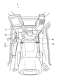
- FIG. 1 shows the crane 1 during traveling.
- FIG. 2 shows the crane 1 during the lifting operation.
- FIG. 3 shows the interior of the cabin 8.
- the crane 1 is mainly composed of a traveling body 2 and a revolving body 3.
- the traveling body 2 includes a pair of left and right front tires 4 and a rear tire 5.
- the traveling body 2 includes an outrigger 6 that is grounded and stabilized when performing the lifting work.
- the traveling body 2 includes an engine, a transmission, and the like in addition to an actuator for driving them.
- the traveling body 2 includes a turning motor 25. For this reason, the traveling body 2 makes the revolving body 3 supported on the upper part freely turnable (see arrow A).
- the revolving unit 3 includes a boom 7 so as to protrude forward from the rear part.
- the boom 7 can be expanded and contracted by an expansion / contraction cylinder 35 (see arrow B). Further, the boom 7 can be raised and lowered by a raising and lowering cylinder 45 (see arrow C).
- the revolving unit 3 includes a cabin 8 on the right side of the boom 7.
- the cabin 8 is provided with a turning lever 8c, an extendable lever 8d, a hoisting lever 8e, and the like which are necessary for a lifting operation, in addition to a handle 8a and a shift lever 8b which are necessary for a traveling operation.
- an emergency key cylinder 8f is arranged in the crane 1, as an emergency key cylinder 8f is arranged.
- the hydraulic system H described below includes various actuators (a turning motor 25, a telescopic cylinder 35, and a hoisting cylinder 45). Furthermore, a main winding motor that constitutes the main winding winch and an auxiliary winding motor that constitutes the auxiliary winding winch may be included.
- FIG. 4 shows the configuration of the hydraulic system H.
- the continuous line and broken line in a figure show a hydraulic circuit
- the dashed-two dotted line in the figure has shown the electric circuit.
- the direction switching valve 20 is arranged in the hydraulic circuit.
- a hydraulic oil pipe 21 is connected to the direction switching valve 20. Therefore, hydraulic oil is supplied to the direction switching valve 20 through the hydraulic oil pipe 21.
- hydraulic oil pipes 22, 23, and 24 are connected to the direction switching valve 20. Therefore, when the spool slides to one side, the hydraulic oil flows to the hydraulic oil pipe 22, and when the spool slides to the other side, the hydraulic oil flows to the hydraulic oil pipe 23. In any case, the hydraulic oil is discharged through the hydraulic oil pipe 24.
- a turning motor 25 is arranged in the hydraulic circuit. Hydraulic oil pipes 22 and 23 are connected to the turning motor 25. Therefore, hydraulic oil is supplied to the turning motor 25 through the hydraulic oil pipe 22 or the hydraulic oil pipe 23.
- the turning motor 25 rotates to one side when the hydraulic oil is supplied through the hydraulic oil pipe 22, and rotates to the other side when the hydraulic oil is supplied through the hydraulic oil pipe 23.
- the turning motor 25 is connected to the turning body 3 through a structure (not shown). Therefore, when the turning motor 25 rotates in one direction, the revolving structure 3 turns in one direction. On the contrary, when the turning motor 25 rotates to the other side, the turning body 3 turns to the other side.
- a proportional pressure reducing valve 26 is arranged in the hydraulic circuit.
- a hydraulic oil pipe 27 is connected to the proportional pressure reducing valve 26. Therefore, hydraulic oil (pilot oil) is supplied to the proportional pressure reducing valve 26 through the hydraulic oil pipe 27.
- one end of the hydraulic oil pipe 28 is connected to the proportional pressure reducing valve 26, and the other end of the hydraulic oil pipe 28 is connected to the direction switching valve 20 described above. For this reason, when the spool is slid small, the pressure of the hydraulic oil (pilot pressure) also decreases, and the spool of the direction switching valve 20 is pushed with a small force.
- a direction switching valve 30 is arranged in the hydraulic circuit.
- a hydraulic oil pipe 31 is connected to the direction switching valve 30. Therefore, hydraulic oil is supplied to the direction switching valve 30 through the hydraulic oil pipe 31.
- hydraulic oil pipes 32, 33, and 34 are connected to the direction switching valve 30. Therefore, when the spool slides to one side, the hydraulic oil flows to the hydraulic oil pipe 32, and when the spool slides to the other side, the hydraulic oil flows to the hydraulic oil pipe 33. In any case, the hydraulic oil is discharged through the hydraulic oil pipe 34.
- a telescopic cylinder 35 is arranged in the hydraulic circuit. Hydraulic oil pipes 32 and 33 are connected to the expansion / contraction cylinder 35. Therefore, the hydraulic oil is supplied to the expansion / contraction cylinder 35 through the hydraulic oil pipe 32 or the hydraulic oil pipe 33.
- the expansion / contraction cylinder 35 expands when the hydraulic oil is supplied through the hydraulic oil pipe 32, and contracts when the hydraulic oil is supplied through the hydraulic oil pipe 33.
- the telescopic cylinder 35 is connected to the boom 7 through a structure (not shown). Therefore, when the telescopic cylinder 35 is extended, the boom 7 is extended accordingly. On the contrary, when the telescopic cylinder 35 contracts, the boom 7 contracts accordingly.
- a proportional pressure reducing valve 36 is arranged in the hydraulic circuit.
- a hydraulic oil pipe 37 is connected to the proportional pressure reducing valve 36. Therefore, hydraulic oil (pilot oil) is supplied to the proportional pressure reducing valve 36 through the hydraulic oil pipe 37.
- one end of a hydraulic oil pipe 38 is connected to the proportional pressure reducing valve 36, and the other end of the hydraulic oil pipe 38 is connected to the direction switching valve 30 described above. For this reason, when the spool is slid small, the pressure of the hydraulic oil (pilot pressure) is also small, and the spool of the direction switching valve 30 is pushed with a small force.
- a direction switching valve 40 is arranged in the hydraulic circuit.
- a hydraulic oil pipe 41 is connected to the direction switching valve 40. Therefore, hydraulic oil is supplied to the direction switching valve 40 through the hydraulic oil pipe 41.
- hydraulic oil pipes 42, 43, and 44 are connected to the direction switching valve 40. Therefore, when the spool slides to one side, the hydraulic oil flows to the hydraulic oil pipe 42, and when the spool slides to the other side, the hydraulic oil flows to the hydraulic oil pipe 43. In any case, the hydraulic oil is discharged through the hydraulic oil pipe 44.
- a undulation cylinder 45 is arranged in the hydraulic circuit. Hydraulic oil pipes 42 and 43 are connected to the undulation cylinder 45. Therefore, hydraulic oil is supplied to the undulation cylinder 45 through the hydraulic oil pipe 42 or the hydraulic oil pipe 43.
- the undulation cylinder 45 expands when the hydraulic oil is supplied through the hydraulic oil pipe 42 and contracts when the hydraulic oil is supplied through the hydraulic oil pipe 43.
- the hoisting cylinder 45 is connected to the boom 7 through a structure (not shown). Therefore, when the hoisting cylinder 45 is extended, the boom 7 is raised accordingly. On the contrary, when the hoisting cylinder 28 contracts, the boom 7 is lowered.
- a proportional pressure reducing valve 46 is arranged in the hydraulic circuit.
- a hydraulic oil pipe 47 is connected to the proportional pressure reducing valve 46. Therefore, hydraulic oil (pilot oil) is supplied to the proportional pressure reducing valve 46 through the hydraulic oil pipe 47.
- one end of the hydraulic oil pipe 48 is connected to the proportional pressure reducing valve 46, and the other end of the hydraulic oil pipe 48 is connected to the direction switching valve 40 described above. Therefore, when the spool is slid small, the hydraulic oil pressure (pilot pressure) is also small, and the spool of the direction switching valve 40 is pushed with a small force.
- an emergency proportional pressure reducing valve 50 is arranged in the hydraulic circuit.
- a hydraulic oil pipe 51 is connected to the emergency proportional pressure reducing valve 50. Therefore, hydraulic oil (pilot oil) is supplied to the emergency proportional pressure reducing valve 50 through the hydraulic oil pipe 51.
- one end of the hydraulic oil pipe 52 is connected to the emergency proportional pressure reducing valve 50 and is branched into the above-described three hydraulic oil pipes 27, 37, and 47. Therefore, when the spool is slid small, the pressure of the hydraulic oil (pilot pressure) is also reduced, and the spools of the respective direction switching valves 20, 30, 40 can be pushed with a small force.
- the position sensor 61 is arranged in the electric circuit. An electric wire 62 is connected to the position sensor 61. The position sensor 61 is attached to the turning lever 8c. Therefore, the position sensor 61 can detect the tilt angle of the turning lever 8c.
- a position sensor 63 is arranged in the electric circuit.
- An electric wire 64 is connected to the position sensor 63.
- the position sensor 63 is attached to the telescopic lever 8d. Therefore, the position sensor 63 can detect the tilt angle of the telescopic lever 8d.
- a position sensor 65 is arranged in the electric circuit.
- An electric wire 66 is connected to the position sensor 65.
- the position sensor 65 is attached to the hoisting lever 8e. Therefore, the position sensor 65 can detect the tilt angle of the hoisting lever 8e.
- an emergency operation switch 67 is arranged in the electric circuit.
- An electric wire 68 is connected to the emergency operation switch 67.
- the emergency operation switch 67 is attached to the emergency key cylinder 8f. Therefore, the emergency operation switch 67 can instruct to perform manual operation by inserting and turning the key.
- a controller 71 is arranged in the electric circuit. Electrical wires 62, 64, 66 and 68 are connected to the controller 71. Therefore, the controller 71 can recognize the tilt angle of the turning lever 8c, the tilt angle of the telescopic lever 8d, the tilt angle of the hoisting lever 8e, and the like.
- the controller 71 is connected to a plurality of electric wires 72, 73, 74, and 75.
- the electric wires 72, 73, 74, and 75 are connected to the proportional pressure reducing valves 26, 36, and 46 and the emergency proportional pressure reducing valve 50. Therefore, the controller 71 can appropriately control these valves 26, 36, 46, and 50.
- the emergency proportional pressure reducing valve 50 is controlled so as to keep the fully open state during normal times. The normal time indicates a situation in which the proportional pressure reducing valves 26, 36, and 46 are not malfunctioning.
- FIG. 5 shows the processing of the controller 71 and the operation for moving the turning motor 25. Here, the description will be made on the assumption that the lifting work has already been performed.
- step S11 the controller 71 determines whether or not the emergency operation switch 67 is “ON”. If the emergency operation switch 67 is “ON”, the process proceeds to step S12.
- step S12 the controller 71 cuts off the energization of the proportional pressure reducing valve 26. Specifically, a signal is sent to a relay circuit (not shown) to cut off the power supplied to the proportional pressure reducing valve 26. Note that the proportional pressure reducing valve 26 is in a fully closed state when the power is cut off, so that the oil passage is closed (closed between the hydraulic oil pipe 27 and the hydraulic oil pipe 28). The reason for immediately stopping the flow of the hydraulic oil is that the oil passage is closed until the operator manually operates the proportional pressure reducing valve 26, and safety is improved.
- step S13 the controller 71 cuts off the energization of the emergency proportional pressure reducing valve 50. Specifically, a signal is sent to a relay circuit (not shown) to cut off the power supplied to the emergency proportional pressure reducing valve 50.
- the emergency proportional pressure reducing valve 50 is also in a fully closed state when the power is cut off, so that the oil passage is closed (closed between the hydraulic oil pipe 51 and the hydraulic oil pipe 52).
- the reason why the flow of hydraulic oil is stopped in a double manner is to improve safety. That is, in addition to the manual operation of the proportional pressure reducing valve 26, the oil passage is closed until the operator manually operates the emergency proportional pressure reducing valve 50, and the safety is further improved.
- step S14 the operator tightens the screw 26s of the proportional pressure reducing valve 26. Specifically, the screw 26s provided in the proportional pressure reducing valve 26 is picked, and the screw 26s is tightened to the end. As a result, the spool of the proportional pressure reducing valve 26 is moved by being pushed by the screw 26s, so that the oil passage can be opened (connecting between the hydraulic oil pipe 27 and the hydraulic oil pipe 28). Note that, in the proportional pressure reducing valve 26, the coil 26s is not excited by cutting off the electric power, so that it is easy to tighten the screw 26s.
- step S15 the operator pushes the push rod 50r of the emergency proportional pressure reducing valve 50.
- the push rod 50r provided in the emergency proportional pressure reducing valve 50 is picked and the push rod 50r is pushed to an appropriate position.
- the spool of the emergency proportional pressure reducing valve 50 is moved by being pushed by the push rod 50r, so that the oil passage can be opened (connecting between the hydraulic oil pipe 51 and the hydraulic oil pipe 52).
- the hydraulic oil pressure (pilot pressure) changes in accordance with the push-in amount of the push rod 50r, the force applied to the spool of the direction switching valve 20 also changes.
- the emergency proportional pressure reducing valve 50 is easy to push in the push rod 50r because the coil is not excited by the power interruption. That is, manual operation is easy. As a result, the hydraulic oil pressure (pilot pressure) can be adjusted quickly and easily.
- step S ⁇ b> 16 the operator determines whether or not the swing body 3 has swung to the storage position of the boom 7. If it is the storage position of the boom 7, it will transfer to step S17.
- step S17 the operator pulls out the push rod 50r of the emergency proportional pressure reducing valve 50. Specifically, the push rod 50r provided in the emergency proportional pressure reducing valve 50 is picked and all the push rods 50r are pulled out. As a result, the spool of the emergency proportional pressure reducing valve 50 moves to the neutral position, so that the oil passage can be closed again (closed between the hydraulic oil pipe 51 and the hydraulic oil pipe 52).
- the crane 1 can adjust the pressure of the hydraulic oil (pilot pressure) by manual operation even when the proportional pressure reducing valve 26 breaks down, and can move the turning motor 25 at an appropriate speed. it can.
- the revolving structure 3 can be revolved to the retracted position of the boom 7.
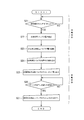
- FIG. 6 shows the processing of the controller 71 and the operation for moving the telescopic cylinder 35.
- the description will be made on the assumption that the lifting work has already been performed.
- step S21 the controller 71 determines whether or not the emergency operation switch 67 is “ON”. If the emergency operation switch 67 is “ON”, the process proceeds to step S22.
- step S22 the controller 71 cuts off the energization of the proportional pressure reducing valve 36. Specifically, a signal is sent to a relay circuit (not shown) to cut off the power supplied to the proportional pressure reducing valve 36. Note that the proportional pressure reducing valve 36 is in a fully closed state when the power is cut off, so that the oil passage is closed (closed between the hydraulic oil pipe 37 and the hydraulic oil pipe 38). The reason for immediately stopping the flow of the hydraulic oil is that the oil passage is closed until the operator manually operates the proportional pressure reducing valve 36, and the safety is improved.
- step S23 the controller 71 cuts off the energization of the emergency proportional pressure reducing valve 50. Specifically, a signal is sent to a relay circuit (not shown) to cut off the power supplied to the emergency proportional pressure reducing valve 50.
- the emergency proportional pressure reducing valve 50 is also in a fully closed state when the power is cut off, so that the oil passage is closed (closed between the hydraulic oil pipe 51 and the hydraulic oil pipe 52).
- the reason why the flow of hydraulic oil is stopped in a double manner is to improve safety. That is, in addition to the manual operation of the proportional pressure reducing valve 36, the oil passage is closed until the operator manually operates the emergency proportional pressure reducing valve 50, and the safety is further improved.
- step S24 the operator tightens the screw 36s of the proportional pressure reducing valve 36. Specifically, the screw 36s provided in the proportional pressure reducing valve 36 is picked, and the screw 36s is tightened to the end. As a result, the spool of the proportional pressure reducing valve 36 is pushed and moved by the screw 36s, so that the oil passage can be opened (connecting between the hydraulic oil pipe 37 and the hydraulic oil pipe 38). Note that, in the proportional pressure reducing valve 36, the coil 36s is not excited by power interruption, so that it is easy to tighten the screw 36s.
- step S25 the operator pushes the push rod 50r of the emergency proportional pressure reducing valve 50.
- the push rod 50r provided in the emergency proportional pressure reducing valve 50 is picked and the push rod 50r is pushed to an appropriate position.
- the spool of the emergency proportional pressure reducing valve 50 is moved by being pushed by the push rod 50r, so that the oil passage can be opened (connecting between the hydraulic oil pipe 51 and the hydraulic oil pipe 52). Since the pressure of the hydraulic oil (pilot pressure) changes according to the push amount of the push rod 50r, the force applied to the spool of the direction switching valve 30 also changes.
- the emergency proportional pressure reducing valve 50 is easy to push in the push rod 50r because the coil is not excited by the power interruption. That is, manual operation is easy. As a result, the hydraulic oil pressure (pilot pressure) can be adjusted quickly and easily.
- step S26 the operator determines whether or not the boom 7 is completely contracted. If the boom 7 is completely contracted, the process proceeds to step S27.
- step S27 the operator pulls out the push rod 50r of the emergency proportional pressure reducing valve 50. Specifically, the push rod 50r provided in the emergency proportional pressure reducing valve 50 is picked and all the push rods 50r are pulled out. As a result, the spool of the emergency proportional pressure reducing valve 50 moves to the neutral position, so that the oil passage can be closed again (closed between the hydraulic oil pipe 51 and the hydraulic oil pipe 52).
- the crane 1 can adjust the pressure of the hydraulic oil (pilot pressure) by manual operation even when the proportional pressure reducing valve 36 is broken, and can move the expansion / contraction cylinder 35 at an appropriate speed. it can.
- the boom 7 can be completely contracted.
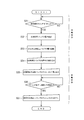
- FIG. 7 shows the processing of the controller 71 and the operation for moving the undulation cylinder 45.
- the description will be made on the assumption that the lifting work has already been performed.
- step S31 the controller 71 determines whether or not the emergency operation switch 67 is “ON”. If the emergency operation switch 67 is “ON”, the process proceeds to step S32.
- step S32 the controller 71 cuts off the energization of the proportional pressure reducing valve 46. Specifically, a signal is sent to a relay circuit (not shown) to cut off the power supplied to the proportional pressure reducing valve 46.
- the proportional pressure reducing valve 46 has a specification in which the proportional pressure reducing valve 46 is fully closed when the power is cut off, so that the oil passage is closed (closed between the hydraulic oil pipe 47 and the hydraulic oil pipe 48). The reason for immediately stopping the flow of the hydraulic oil is that the oil passage is closed until the operator manually operates the proportional pressure reducing valve 46, and safety is improved.
- step S33 the controller 71 cuts off the energization of the emergency proportional pressure reducing valve 50. Specifically, a signal is sent to a relay circuit (not shown) to cut off the power supplied to the emergency proportional pressure reducing valve 50.
- the emergency proportional pressure reducing valve 50 is also in a fully closed state when the power is shut off, so that the hydraulic oil passage is closed (between the hydraulic oil pipe 51 and the hydraulic oil pipe 52). Become.
- the reason why the flow of hydraulic oil is stopped in a double manner is to improve safety. That is, in addition to the manual operation of the proportional pressure reducing valve 46, the oil passage is closed until the operator manually operates the emergency proportional pressure reducing valve 50, and the safety is further improved.
- step S34 the operator tightens the screw 46s of the proportional pressure reducing valve 46. Specifically, the screw 46s provided in the proportional pressure reducing valve 46 is picked and the screw 46s is tightened to the end. As a result, the spool of the proportional pressure reducing valve 46 is moved by being pushed by the screw 46s, so that the oil passage can be opened (the connection between the hydraulic oil pipe 37 and the hydraulic oil pipe 38). In the proportional pressure reducing valve 46, since the coil is not excited by the power interruption, it is easy to tighten the screw 46s.
- step S35 the operator pushes the push rod 50r of the emergency proportional pressure reducing valve 50.
- the push rod 50r provided in the emergency proportional pressure reducing valve 50 is picked and the push rod 50r is pushed to an appropriate position.
- the spool of the emergency proportional pressure reducing valve 50 is moved by being pushed by the push rod 50r, so that the oil passage can be opened (connecting between the hydraulic oil pipe 51 and the hydraulic oil pipe 52). Since the pressure of the hydraulic oil (pilot pressure) changes according to the push amount of the push rod 50r, the force applied to the spool of the direction switching valve 40 also changes.
- the emergency proportional pressure reducing valve 50 is easy to push in the push rod 50r because the coil is not excited by the power interruption. That is, manual operation is easy. As a result, the hydraulic oil pressure (pilot pressure) can be adjusted quickly and easily.
- step S36 the operator determines whether or not the boom 7 is completely lying down. If the boom 7 is completely lying down, the process proceeds to step S37.
- step S37 the operator pulls out the push rod 50r of the emergency proportional pressure reducing valve 50. Specifically, the push rod 50r provided in the emergency proportional pressure reducing valve 50 is picked and all the push rods 50r are pulled out. As a result, the spool of the emergency proportional pressure reducing valve 50 moves to the neutral position, so that the oil passage can be closed again (closed between the hydraulic oil pipe 51 and the hydraulic oil pipe 52).
- the crane 1 can adjust the pressure (pilot pressure) of the hydraulic oil by manual operation even when the proportional pressure reducing valve 46 is broken, and can move the hoisting cylinder 45 at an appropriate speed. it can.
- the boom 7 can be completely laid down.
- the crane 1 is provided with oil passages (hydraulic oil pipes 51 and 52) for guiding hydraulic oil to one or a plurality of proportional pressure reducing valves 26, 36 and 46, and the oil passages (51 and 52).
- An emergency proportional pressure reducing valve 50 that can adjust the opening degree by manual operation is arranged.
- the emergency proportional pressure reducing valve 50 is controlled so as to be kept fully open during normal times, and is a manual operation tool for adjusting the pressure of hydraulic oil without being controlled during emergency times. According to the crane 1, even when the proportional pressure reducing valves 26, 36, 46 are out of order, the hydraulic oil pressure can be adjusted by manual operation of the emergency proportional pressure reducing valve 50.
- the actuator the turning motor 25, the expansion / contraction cylinder 35, and the hoisting cylinder 45
- the actuator can be moved at an appropriate speed.
- the crane 1 further includes a controller 71 that can control the emergency proportional pressure reducing valve 50 and an emergency operation switch 67 that can instruct the controller 71 to perform an emergency operation. Then, when the emergency operation switch 67 is turned on, the controller 71 cuts off the power supplied to the emergency proportional pressure reducing valve 50. According to the crane 1, manual operation of the emergency proportional pressure reducing valve 50 is facilitated, so that the pressure of the hydraulic oil can be adjusted quickly and easily.
- the emergency proportional pressure reducing valve 50 is a specification that is fully closed when the power is cut off. According to the crane 1, the oil passage is closed until the operator manually operates the emergency proportional pressure reducing valve 50, so that safety can be further improved.
Abstract
Provided is a crane 1 constituting a hydraulic system H that includes: actuators 25, 35, 45; direction switching valves 20, 30, 40 that switch the flow direction of an operating fluid for actuating the actuators 25, 35, 45; and proportional depressurization valves 26, 36, 46 that enable the adjustment of the pressure of an operating fluid for actuating the direction switching valves 20, 30, 40, wherein flow passages 51, 52 are provided for guiding the operating fluid to one or a plurality of the proportional depressurization valves 26, 36, 46, and an emergency proportional depressurization valve 50, the opening degree of which can be adjusted with a manual operation is disposed in the flow passages 51, 52. The emergency proportional depressurization valve 50 is controlled so as to maintain a fully-open state during normal times and serves as a manually operable tool for adjusting the pressure of the operating fluid without being controlled during an emergency.
Description
本発明は、クレーンに関する。
The present invention relates to a crane.
従来より、荷を吊り上げて運搬するクレーンが知られている(特許文献1参照)。クレーンは、アクチュエータと、アクチュエータを動かす作動油の流動方向を切り替える方向切替バルブと、方向切替バルブを動かす作動油の圧力を調整自在とする比例減圧バルブと、を含んだ油圧システムを構成している。
Conventionally, a crane that lifts and carries a load is known (see Patent Document 1). The crane constitutes a hydraulic system that includes an actuator, a direction switching valve that switches a flow direction of hydraulic oil that moves the actuator, and a proportional pressure reducing valve that can adjust the pressure of hydraulic fluid that moves the direction switching valve. .
ところで、圧力調整用のネジを備えた比例減圧バルブが存在している。このような比例減圧バルブは、非通電時においても、ネジを締め込むことで油路を開けることができる。そのため、このような比例減圧バルブを採用したクレーンは、比例減圧バルブが故障するという非常時においても、そのネジを締め込むことでアクチュエータを動かすことが可能である。しかし、非常時においては、電力が遮断されて圧力を調整することができないため、アクチュエータの作動速度を予め制限しておく必要があり、かかる事情から非常時における作動速度が緩慢であるという問題を有していた。そこで、比例減圧バルブが故障した場合であっても、手動操作によって作動油の圧力を調整でき、ひいては適宜な速度でアクチュエータを動かすことができるクレーンが求められていたのである。
By the way, there is a proportional pressure reducing valve equipped with a pressure adjusting screw. Such a proportional pressure reducing valve can open an oil passage by tightening a screw even when not energized. Therefore, a crane employing such a proportional pressure reducing valve can move the actuator by tightening the screw even in an emergency where the proportional pressure reducing valve fails. However, since the electric power is cut off and the pressure cannot be adjusted in an emergency, it is necessary to limit the operating speed of the actuator in advance, and the problem is that the operating speed in an emergency is slow due to such circumstances. Had. Therefore, there has been a demand for a crane that can adjust the pressure of hydraulic oil by manual operation and can move the actuator at an appropriate speed even when the proportional pressure reducing valve fails.
比例減圧バルブが故障した場合であっても、手動操作によって作動油の圧力を調整でき、ひいては適宜な速度でアクチュエータを動かすことができるクレーンを提供する。
ク レ ー ン Provide a crane that can adjust the pressure of hydraulic oil by manual operation and can move the actuator at an appropriate speed even when the proportional pressure reducing valve fails.
第一の発明は、
アクチュエータと、
前記アクチュエータを動かす作動油の流動方向を切り替える方向切替バルブと、
前記方向切替バルブを動かす作動油の圧力を調整自在とする比例減圧バルブと、を含んだ油圧システムを構成しているクレーンにおいて、
一つ又は複数の前記比例減圧バルブに作動油を案内する油路を設けるとともに、
前記油路に手動操作によって開度を調整できる非常用比例減圧バルブを配置し、
前記非常用比例減圧バルブは、通常時にあっては全開状態を保つように制御され、非常時にあっては制御されることなく作動油の圧力を調整するための手動操作具となる、としたものである。 The first invention is
An actuator,
A direction switching valve that switches a flow direction of hydraulic oil that moves the actuator;
In a crane that constitutes a hydraulic system including a proportional pressure reducing valve that can adjust the pressure of hydraulic oil that moves the direction switching valve,
Providing an oil passage for guiding hydraulic oil to one or more of the proportional pressure reducing valves;
An emergency proportional pressure reducing valve that can adjust the opening degree by manual operation is disposed in the oil passage,
The emergency proportional pressure reducing valve is controlled so as to be kept fully open during normal times, and is a manual operation tool for adjusting the pressure of hydraulic oil without being controlled during emergency times. It is.
第二の発明は、第一の発明に係るクレーンにおいて、
前記非常用比例減圧バルブを制御できるコントローラと、
前記コントローラに非常操作を行なう旨を指示できる非常操作スイッチと、を具備し、
前記コントローラは、前記非常操作スイッチが「オン」になると、前記非常用比例減圧バルブへ供給される電力を遮断する、としたものである。 The second invention is the crane according to the first invention,
A controller capable of controlling the emergency proportional pressure reducing valve;
An emergency operation switch capable of instructing the controller to perform an emergency operation,
The controller is configured to cut off power supplied to the emergency proportional pressure reducing valve when the emergency operation switch is turned on.
第三の発明は、第二の発明に係るクレーンにおいて、
前記非常用比例減圧バルブは、電力遮断時に全閉状態となる仕様である、としたものである。 The third invention is the crane according to the second invention,
The emergency proportional pressure reducing valve is designed to be fully closed when power is cut off.
前記非常用比例減圧バルブは、電力遮断時に全閉状態となる仕様である、としたものである。 The third invention is the crane according to the second invention,
The emergency proportional pressure reducing valve is designed to be fully closed when power is cut off.
第一の発明に係るクレーンは、一つ又は複数の比例減圧バルブに作動油を案内する油路を設けるとともに、油路に手動操作によって開度を調整できる非常用比例減圧バルブを配置している。そして、非常用比例減圧バルブは、通常時にあっては全開状態を保つように制御され、非常時にあっては制御されることなく作動油の圧力を調整するための手動操作具となる。かかるクレーンによれば、比例減圧バルブが故障した場合であっても、非常用比例減圧バルブの手動操作によって作動油の圧力を調整できる。ひいては適宜な速度でアクチュエータを動かすことができる。
In the crane according to the first invention, an oil passage for guiding hydraulic oil is provided in one or a plurality of proportional pressure reducing valves, and an emergency proportional pressure reducing valve capable of adjusting an opening degree by manual operation is disposed in the oil passage. . The emergency proportional pressure reducing valve is controlled so as to be kept fully open during normal times, and becomes a manual operation tool for adjusting the pressure of hydraulic oil without being controlled during emergency. According to such a crane, even if the proportional pressure reducing valve fails, the pressure of the hydraulic oil can be adjusted by manual operation of the emergency proportional pressure reducing valve. As a result, the actuator can be moved at an appropriate speed.
第二の発明に係るクレーンは、第一の発明に係るクレーンを具体的に限定する。即ち、第二の発明に係るクレーンは、非常用比例減圧バルブを制御できるコントローラと、コントローラに非常操作を行なう旨を指示できる非常操作スイッチと、を具備している。そして、コントローラは、非常操作スイッチが「オン」になると、非常用比例減圧バルブへ供給される電力を遮断する。かかるクレーンによれば、非常用比例減圧バルブの手動操作が容易になるので、素早く簡単に作動油の圧力を調整できる。
The crane according to the second invention specifically limits the crane according to the first invention. In other words, the crane according to the second aspect of the invention includes a controller that can control the emergency proportional pressure reducing valve and an emergency operation switch that can instruct the controller to perform an emergency operation. When the emergency operation switch is turned “ON”, the controller cuts off the power supplied to the emergency proportional pressure reducing valve. According to such a crane, manual operation of the emergency proportional pressure reducing valve is facilitated, so that the pressure of the hydraulic oil can be adjusted quickly and easily.
第三の発明に係るクレーンは、第二の発明に係るクレーンを具体的に限定する。即ち、非常用比例減圧バルブは、電力遮断時に全閉状態となる仕様である。かかるクレーンによれば、オペレータが非常用比例減圧バルブを手動操作するまで油路が閉塞された状態となるので、より安全性を向上させることができる。
The crane according to the third invention specifically limits the crane according to the second invention. That is, the emergency proportional pressure reducing valve has a specification that is fully closed when the power is cut off. According to such a crane, since the oil passage is closed until the operator manually operates the emergency proportional pressure reducing valve, the safety can be further improved.
本発明の技術的思想は、以下に説明するクレーン1のほか、他の作業車両にも適用できる。
The technical idea of the present invention can be applied to other work vehicles in addition to the crane 1 described below.
まず、クレーン1について簡単に説明する。
First, the crane 1 will be briefly described.
図1は、走行時におけるクレーン1を示している。図2は、吊上作業時におけるクレーン1を示している。そして、図3は、キャビン8の内部を示している。
FIG. 1 shows the crane 1 during traveling. FIG. 2 shows the crane 1 during the lifting operation. FIG. 3 shows the interior of the cabin 8.
クレーン1は、主に走行体2と旋回体3で構成されている。
The crane 1 is mainly composed of a traveling body 2 and a revolving body 3.
走行体2は、左右一対のフロントタイヤ4とリヤタイヤ5を備えている。また、走行体2は、吊上作業を行なう際に接地させて安定を図るアウトリガ6を備えている。更に、走行体2は、これらを駆動するためのアクチュエータに加え、エンジンやトランスミッションなどを備えている。なお、走行体2は、旋回用モータ25を備えている。このため、走行体2は、その上部に支持する旋回体3を旋回自在としている(矢印A参照)。
The traveling body 2 includes a pair of left and right front tires 4 and a rear tire 5. In addition, the traveling body 2 includes an outrigger 6 that is grounded and stabilized when performing the lifting work. Furthermore, the traveling body 2 includes an engine, a transmission, and the like in addition to an actuator for driving them. The traveling body 2 includes a turning motor 25. For this reason, the traveling body 2 makes the revolving body 3 supported on the upper part freely turnable (see arrow A).
旋回体3は、その後部から前方へ突き出すようにブーム7を備えている。ブーム7は、伸縮用シリンダ35によって伸縮自在となっている(矢印B参照)。また、ブーム7は、起伏用シリンダ45によって起伏自在となっている(矢印C参照)。なお、旋回体3は、ブーム7の右方にキャビン8を備えている。キャビン8には、走行操作に必要となるハンドル8aやシフトレバー8bなどに加え、吊上作業の操作に必要となる旋回レバー8cや伸縮レバー8d、起伏レバー8eなどが配置されている。また、本クレーン1においては、非常時用キーシリンダ8fが配置されている。
The revolving unit 3 includes a boom 7 so as to protrude forward from the rear part. The boom 7 can be expanded and contracted by an expansion / contraction cylinder 35 (see arrow B). Further, the boom 7 can be raised and lowered by a raising and lowering cylinder 45 (see arrow C). The revolving unit 3 includes a cabin 8 on the right side of the boom 7. The cabin 8 is provided with a turning lever 8c, an extendable lever 8d, a hoisting lever 8e, and the like which are necessary for a lifting operation, in addition to a handle 8a and a shift lever 8b which are necessary for a traveling operation. In the crane 1, an emergency key cylinder 8f is arranged.
次に、クレーン1の油圧システムHについて説明する。
Next, the hydraulic system H of the crane 1 will be described.
以下に説明する油圧システムHは、各種のアクチュエータ(旋回用モータ25・伸縮用シリンダ35・起伏用シリンダ45)を含んでいる。更に、主巻ウインチを構成する主巻用モータや補巻ウインチを構成する補巻用モータを含むとしてもよい。
The hydraulic system H described below includes various actuators (a turning motor 25, a telescopic cylinder 35, and a hoisting cylinder 45). Furthermore, a main winding motor that constitutes the main winding winch and an auxiliary winding motor that constitutes the auxiliary winding winch may be included.
図4は、油圧システムHの構成を示している。なお、図中の実線と破線は、油圧回路を示し、図中の二点鎖線は、電気回路を示している。
FIG. 4 shows the configuration of the hydraulic system H. In addition, the continuous line and broken line in a figure show a hydraulic circuit, and the dashed-two dotted line in the figure has shown the electric circuit.
まず、油圧回路について説明する。
First, the hydraulic circuit will be described.
油圧回路には、方向切替バルブ20が配置されている。方向切替バルブ20には、作動油パイプ21が接続されている。そのため、方向切替バルブ20には、作動油が作動油パイプ21を通って供給される。なお、方向切替バルブ20には、作動油パイプ22・23・24が接続されている。そのため、スプールが一方へ摺動したときは、作動油が作動油パイプ22へ流れることとなり、スプールが他方へ摺動したときは、作動油が作動油パイプ23へ流れることとなる。また、いずれであっても、作動油が作動油パイプ24を通って排出されることとなる。
The direction switching valve 20 is arranged in the hydraulic circuit. A hydraulic oil pipe 21 is connected to the direction switching valve 20. Therefore, hydraulic oil is supplied to the direction switching valve 20 through the hydraulic oil pipe 21. Note that hydraulic oil pipes 22, 23, and 24 are connected to the direction switching valve 20. Therefore, when the spool slides to one side, the hydraulic oil flows to the hydraulic oil pipe 22, and when the spool slides to the other side, the hydraulic oil flows to the hydraulic oil pipe 23. In any case, the hydraulic oil is discharged through the hydraulic oil pipe 24.
更に、油圧回路には、旋回用モータ25が配置されている。旋回用モータ25には、作動油パイプ22・23が接続されている。そのため、旋回用モータ25には、作動油が作動油パイプ22若しくは作動油パイプ23を通って供給される。なお、旋回用モータ25は、作動油が作動油パイプ22を通って供給された場合に一方へ回転し、作動油が作動油パイプ23を通って供給された場合に他方へ回転する。また、旋回用モータ25は、図示しない構造を介して旋回体3と連結している。そのため、旋回用モータ25が一方へ回転したときは、旋回体3が一方へ旋回することとなる。反対に、旋回用モータ25が他方へ回転したときは、旋回体3が他方へ旋回することとなる。
Furthermore, a turning motor 25 is arranged in the hydraulic circuit. Hydraulic oil pipes 22 and 23 are connected to the turning motor 25. Therefore, hydraulic oil is supplied to the turning motor 25 through the hydraulic oil pipe 22 or the hydraulic oil pipe 23. The turning motor 25 rotates to one side when the hydraulic oil is supplied through the hydraulic oil pipe 22, and rotates to the other side when the hydraulic oil is supplied through the hydraulic oil pipe 23. Further, the turning motor 25 is connected to the turning body 3 through a structure (not shown). Therefore, when the turning motor 25 rotates in one direction, the revolving structure 3 turns in one direction. On the contrary, when the turning motor 25 rotates to the other side, the turning body 3 turns to the other side.
更に、油圧回路には、比例減圧バルブ26が配置されている。比例減圧バルブ26には、作動油パイプ27が接続されている。そのため、比例減圧バルブ26には、作動油(パイロット油)が作動油パイプ27を通って供給される。なお、比例減圧バルブ26には、作動油パイプ28の一端が接続されており、上述した方向切替バルブ20には、作動油パイプ28の他端が接続されている。そのため、スプールを小さく摺動させたときは、作動油の圧力(パイロット圧)も小さくなり、方向切替バルブ20のスプールを小さな力で押すこととなる。反対に、スプールを大きく摺動させたときは、作動油の圧力(パイロット圧)も大きくなり、方向切替バルブ20のスプールを大きな力で押すこととなる。こうして、方向切替バルブ20における油路面積が変わるので、旋回用モータ25へ送られる作動油の流量も変わり、該旋回用モータ25の回転速度(作動速度)が増速若しくは減速されることとなる。ひいては、旋回体3の旋回速度が増速若しくは減速されることとなる。
Furthermore, a proportional pressure reducing valve 26 is arranged in the hydraulic circuit. A hydraulic oil pipe 27 is connected to the proportional pressure reducing valve 26. Therefore, hydraulic oil (pilot oil) is supplied to the proportional pressure reducing valve 26 through the hydraulic oil pipe 27. Note that one end of the hydraulic oil pipe 28 is connected to the proportional pressure reducing valve 26, and the other end of the hydraulic oil pipe 28 is connected to the direction switching valve 20 described above. For this reason, when the spool is slid small, the pressure of the hydraulic oil (pilot pressure) also decreases, and the spool of the direction switching valve 20 is pushed with a small force. On the other hand, when the spool is slid largely, the pressure of the hydraulic oil (pilot pressure) also increases, and the spool of the direction switching valve 20 is pushed with a large force. Thus, since the oil passage area in the direction switching valve 20 changes, the flow rate of the hydraulic oil sent to the turning motor 25 also changes, and the rotational speed (operating speed) of the turning motor 25 increases or decreases. . Eventually, the turning speed of the revolving structure 3 is increased or decreased.
また、油圧回路には、方向切替バルブ30が配置されている。方向切替バルブ30には、作動油パイプ31が接続されている。そのため、方向切替バルブ30には、作動油が作動油パイプ31を通って供給される。なお、方向切替バルブ30には、作動油パイプ32・33・34が接続されている。そのため、スプールが一方へ摺動したときは、作動油が作動油パイプ32へ流れることとなり、スプールが他方へ摺動したときは、作動油が作動油パイプ33へ流れることとなる。また、いずれであっても、作動油が作動油パイプ34を通って排出されることとなる。
Further, a direction switching valve 30 is arranged in the hydraulic circuit. A hydraulic oil pipe 31 is connected to the direction switching valve 30. Therefore, hydraulic oil is supplied to the direction switching valve 30 through the hydraulic oil pipe 31. Note that hydraulic oil pipes 32, 33, and 34 are connected to the direction switching valve 30. Therefore, when the spool slides to one side, the hydraulic oil flows to the hydraulic oil pipe 32, and when the spool slides to the other side, the hydraulic oil flows to the hydraulic oil pipe 33. In any case, the hydraulic oil is discharged through the hydraulic oil pipe 34.
更に、油圧回路には、伸縮用シリンダ35が配置されている。伸縮用シリンダ35には、作動油パイプ32・33が接続されている。そのため、伸縮用シリンダ35には、作動油が作動油パイプ32若しくは作動油パイプ33を通って供給される。なお、伸縮用シリンダ35は、作動油が作動油パイプ32を通って供給された場合に伸張し、作動油が作動油パイプ33を通って供給された場合に収縮する。また、伸縮用シリンダ35は、図示しない構造を介してブーム7と連結している。そのため、伸縮用シリンダ35が伸張したときは、それに伴ってブーム7が伸びていくこととなる。反対に、伸縮用シリンダ35が収縮したときは、それに伴ってブーム7が縮んでいくこととなる。
Furthermore, a telescopic cylinder 35 is arranged in the hydraulic circuit. Hydraulic oil pipes 32 and 33 are connected to the expansion / contraction cylinder 35. Therefore, the hydraulic oil is supplied to the expansion / contraction cylinder 35 through the hydraulic oil pipe 32 or the hydraulic oil pipe 33. The expansion / contraction cylinder 35 expands when the hydraulic oil is supplied through the hydraulic oil pipe 32, and contracts when the hydraulic oil is supplied through the hydraulic oil pipe 33. The telescopic cylinder 35 is connected to the boom 7 through a structure (not shown). Therefore, when the telescopic cylinder 35 is extended, the boom 7 is extended accordingly. On the contrary, when the telescopic cylinder 35 contracts, the boom 7 contracts accordingly.
更に、油圧回路には、比例減圧バルブ36が配置されている。比例減圧バルブ36には、作動油パイプ37が接続されている。そのため、比例減圧バルブ36には、作動油(パイロット油)が作動油パイプ37を通って供給される。なお、比例減圧バルブ36には、作動油パイプ38の一端が接続されており、上述した方向切替バルブ30には、作動油パイプ38の他端が接続されている。そのため、スプールを小さく摺動させたときは、作動油の圧力(パイロット圧)も小さく、方向切替バルブ30のスプールを小さな力で押すこととなる。反対に、スプールを大きく摺動させたときは、作動油の圧力(パイロット圧)も大きく、方向切替バルブ30のスプールを大きな力で押すこととなる。こうして、方向切替バルブ30における油路面積が変わるので、伸縮用シリンダ35へ送られる作動油の流量も変わり、該伸縮用シリンダ35の伸縮速度(作動速度)が増速若しくは減速されることとなる。ひいては、ブーム7の伸縮速度が増速若しくは減速されることとなる。
Furthermore, a proportional pressure reducing valve 36 is arranged in the hydraulic circuit. A hydraulic oil pipe 37 is connected to the proportional pressure reducing valve 36. Therefore, hydraulic oil (pilot oil) is supplied to the proportional pressure reducing valve 36 through the hydraulic oil pipe 37. Note that one end of a hydraulic oil pipe 38 is connected to the proportional pressure reducing valve 36, and the other end of the hydraulic oil pipe 38 is connected to the direction switching valve 30 described above. For this reason, when the spool is slid small, the pressure of the hydraulic oil (pilot pressure) is also small, and the spool of the direction switching valve 30 is pushed with a small force. On the other hand, when the spool is slid largely, the pressure of the hydraulic oil (pilot pressure) is also large, and the spool of the direction switching valve 30 is pushed with a large force. Thus, since the oil passage area in the direction switching valve 30 changes, the flow rate of the hydraulic oil sent to the expansion / contraction cylinder 35 also changes, and the expansion / contraction speed (operation speed) of the expansion / contraction cylinder 35 increases or decreases. . As a result, the expansion / contraction speed of the boom 7 is increased or decreased.
また、油圧回路には、方向切替バルブ40が配置されている。方向切替バルブ40には、作動油パイプ41が接続されている。そのため、方向切替バルブ40には、作動油が作動油パイプ41を通って供給される。なお、方向切替バルブ40には、作動油パイプ42・43・44が接続されている。そのため、スプールが一方へ摺動したときは、作動油が作動油パイプ42へ流れることとなり、スプールが他方へ摺動したときは、作動油が作動油パイプ43へ流れることとなる。また、いずれであっても、作動油が作動油パイプ44を通って排出されることとなる。
Also, a direction switching valve 40 is arranged in the hydraulic circuit. A hydraulic oil pipe 41 is connected to the direction switching valve 40. Therefore, hydraulic oil is supplied to the direction switching valve 40 through the hydraulic oil pipe 41. Note that hydraulic oil pipes 42, 43, and 44 are connected to the direction switching valve 40. Therefore, when the spool slides to one side, the hydraulic oil flows to the hydraulic oil pipe 42, and when the spool slides to the other side, the hydraulic oil flows to the hydraulic oil pipe 43. In any case, the hydraulic oil is discharged through the hydraulic oil pipe 44.
更に、油圧回路には、起伏用シリンダ45が配置されている。起伏用シリンダ45には、作動油パイプ42・43が接続されている。そのため、起伏用シリンダ45には、作動油が作動油パイプ42若しくは作動油パイプ43を通って供給される。なお、起伏用シリンダ45は、作動油が作動油パイプ42を通って供給された場合に伸張し、作動油が作動油パイプ43を通って供給された場合に収縮する。また、起伏用シリンダ45は、図示しない構造を介してブーム7と連結している。そのため、起伏用シリンダ45が伸張したときは、それに伴ってブーム7が起きていくこととなる。反対に、起伏用シリンダ28が収縮したときは、それに伴ってブーム7が伏せていくこととなる。
Furthermore, a undulation cylinder 45 is arranged in the hydraulic circuit. Hydraulic oil pipes 42 and 43 are connected to the undulation cylinder 45. Therefore, hydraulic oil is supplied to the undulation cylinder 45 through the hydraulic oil pipe 42 or the hydraulic oil pipe 43. The undulation cylinder 45 expands when the hydraulic oil is supplied through the hydraulic oil pipe 42 and contracts when the hydraulic oil is supplied through the hydraulic oil pipe 43. The hoisting cylinder 45 is connected to the boom 7 through a structure (not shown). Therefore, when the hoisting cylinder 45 is extended, the boom 7 is raised accordingly. On the contrary, when the hoisting cylinder 28 contracts, the boom 7 is lowered.
更に、油圧回路には、比例減圧バルブ46が配置されている。比例減圧バルブ46には、作動油パイプ47が接続されている。そのため、比例減圧バルブ46には、作動油(パイロット油)が作動油パイプ47を通って供給される。なお、比例減圧バルブ46には、作動油パイプ48の一端が接続されており、上述した方向切替バルブ40には、作動油パイプ48の他端が接続されている。そのため、スプールを小さく摺動させたときは、作動油の圧力(パイロット圧)も小さく、方向切替バルブ40のスプールを小さな力で押すこととなる。反対に、スプールを大きく摺動させたときは、作動油の圧力(パイロット圧)も大きく、方向切替バルブ40のスプールを大きな力で押すこととなる。こうして、方向切替バルブ40における油路面積が変わるので、起伏用シリンダ45へ送られる作動油の流量も変わり、該起伏用シリンダ45の伸縮速度(作動速度)が増速若しくは減速されることとなる。ひいては、ブーム7の起伏速度が増速若しくは減速されることとなる。
Furthermore, a proportional pressure reducing valve 46 is arranged in the hydraulic circuit. A hydraulic oil pipe 47 is connected to the proportional pressure reducing valve 46. Therefore, hydraulic oil (pilot oil) is supplied to the proportional pressure reducing valve 46 through the hydraulic oil pipe 47. Note that one end of the hydraulic oil pipe 48 is connected to the proportional pressure reducing valve 46, and the other end of the hydraulic oil pipe 48 is connected to the direction switching valve 40 described above. Therefore, when the spool is slid small, the hydraulic oil pressure (pilot pressure) is also small, and the spool of the direction switching valve 40 is pushed with a small force. On the other hand, when the spool is slid largely, the pressure of the hydraulic oil (pilot pressure) is also large, and the spool of the direction switching valve 40 is pushed with a large force. Thus, since the oil passage area in the direction switching valve 40 changes, the flow rate of the hydraulic oil sent to the undulation cylinder 45 also changes, and the expansion / contraction speed (operation speed) of the undulation cylinder 45 is increased or decreased. . As a result, the hoisting speed of the boom 7 is increased or decreased.
加えて、油圧回路には、非常用比例減圧バルブ50が配置されている。非常用比例減圧バルブ50には、作動油パイプ51が接続されている。そのため、非常用比例減圧バルブ50には、作動油(パイロット油)が作動油パイプ51を通って供給される。なお、非常用比例減圧バルブ50には、作動油パイプ52の一端が接続されており、その途中で上述した三つの作動油パイプ27・37・47に分岐している。そのため、スプールを小さく摺動させたときは、作動油の圧力(パイロット圧)も小さくなり、それぞれの方向切替バルブ20・30・40のスプールを小さな力で押すことができる。反対に、スプールを大きく摺動させたときは、作動油の圧力(パイロット圧)も大きくなり、それぞれの方向切替バルブ20・30・40のスプールを大きな力で押すことができる。すると、旋回用モータ25にあっては、比例減圧バルブ26を制御するのと同様に、回転速度(作動速度)が増速若しくは減速されることとなる。ひいては、旋回体3の旋回速度が増速若しくは減速されることとなる。また、伸縮用シリンダ35にあっては、比例減圧バルブ36を制御するのと同様に、伸縮速度(作動速度)が増速若しくは減速されることとなる。ひいては、ブーム7の伸縮速度が増速若しくは減速されることとなる。更に、起伏用シリンダ45にあっては、比例減圧バルブ46を制御するのと同様に、伸縮速度(作動速度)が増速若しくは減速されることとなる。ひいては、ブーム7の起伏速度が増速若しくは減速されることとなる。
In addition, an emergency proportional pressure reducing valve 50 is arranged in the hydraulic circuit. A hydraulic oil pipe 51 is connected to the emergency proportional pressure reducing valve 50. Therefore, hydraulic oil (pilot oil) is supplied to the emergency proportional pressure reducing valve 50 through the hydraulic oil pipe 51. Note that one end of the hydraulic oil pipe 52 is connected to the emergency proportional pressure reducing valve 50 and is branched into the above-described three hydraulic oil pipes 27, 37, and 47. Therefore, when the spool is slid small, the pressure of the hydraulic oil (pilot pressure) is also reduced, and the spools of the respective direction switching valves 20, 30, 40 can be pushed with a small force. On the contrary, when the spool is slid largely, the pressure of the hydraulic oil (pilot pressure) also increases, and the spool of each direction switching valve 20, 30, 40 can be pushed with a large force. Then, in the turning motor 25, the rotational speed (operating speed) is increased or decreased in the same manner as the proportional pressure reducing valve 26 is controlled. Eventually, the turning speed of the revolving structure 3 is increased or decreased. In the expansion / contraction cylinder 35, the expansion / contraction speed (operation speed) is increased or decreased in the same manner as the proportional pressure reducing valve 36 is controlled. As a result, the expansion / contraction speed of the boom 7 is increased or decreased. Further, in the undulation cylinder 45, the expansion / contraction speed (operation speed) is increased or decreased in the same manner as the proportional pressure reducing valve 46 is controlled. As a result, the hoisting speed of the boom 7 is increased or decreased.
次に、電気回路について説明する。
Next, the electric circuit will be described.
電気回路には、位置センサ61が配置されている。位置センサ61には、電気線62が接続されている。なお、位置センサ61は、旋回レバー8cに取り付けられている。そのため、位置センサ61は、旋回レバー8cの傾倒角度を検出できる。
The position sensor 61 is arranged in the electric circuit. An electric wire 62 is connected to the position sensor 61. The position sensor 61 is attached to the turning lever 8c. Therefore, the position sensor 61 can detect the tilt angle of the turning lever 8c.
更に、電気回路には、位置センサ63が配置されている。位置センサ63には、電気線64が接続されている。なお、位置センサ63は、伸縮レバー8dに取り付けられている。そのため、位置センサ63は、伸縮レバー8dの傾倒角度を検出できる。
Furthermore, a position sensor 63 is arranged in the electric circuit. An electric wire 64 is connected to the position sensor 63. The position sensor 63 is attached to the telescopic lever 8d. Therefore, the position sensor 63 can detect the tilt angle of the telescopic lever 8d.
更に、電気回路には、位置センサ65が配置されている。位置センサ65には、電気線66が接続されている。なお、位置センサ65は、起伏レバー8eに取り付けられている。そのため、位置センサ65は、起伏レバー8eの傾倒角度を検出できる。
Furthermore, a position sensor 65 is arranged in the electric circuit. An electric wire 66 is connected to the position sensor 65. The position sensor 65 is attached to the hoisting lever 8e. Therefore, the position sensor 65 can detect the tilt angle of the hoisting lever 8e.
更に、電気回路には、非常操作スイッチ67が配置されている。非常操作スイッチ67には、電気線68が接続されている。なお、非常操作スイッチ67は、非常時用キーシリンダ8fに取り付けられている。そのため、非常操作スイッチ67は、キーを差し込んで回すことで手動操作を行なう旨を指示することができる。
Furthermore, an emergency operation switch 67 is arranged in the electric circuit. An electric wire 68 is connected to the emergency operation switch 67. The emergency operation switch 67 is attached to the emergency key cylinder 8f. Therefore, the emergency operation switch 67 can instruct to perform manual operation by inserting and turning the key.
更に、電気回路には、コントローラ71が配置されている。コントローラ71には、電気線62・64・66・68が接続されている。そのため、コントローラ71は、旋回レバー8cの傾倒角度や伸縮レバー8dの傾倒角度、起伏レバー8eの傾倒角度などを認識することができる。なお、コントローラ71には、複数の電気線72・73・74・75が接続されている。そして、これらの電気線72・73・74・75は、各比例減圧バルブ26・36・46および非常用比例減圧バルブ50に接続されている。そのため、コントローラ71は、これらバルブ26・36・46・50を適宜に制御することができる。但し、本クレーン1において、非常用比例減圧バルブ50は、通常時にあっては全開状態を保つように制御されている。通常時とは、比例減圧バルブ26・36・46が故障していない状況を指す。
Furthermore, a controller 71 is arranged in the electric circuit. Electrical wires 62, 64, 66 and 68 are connected to the controller 71. Therefore, the controller 71 can recognize the tilt angle of the turning lever 8c, the tilt angle of the telescopic lever 8d, the tilt angle of the hoisting lever 8e, and the like. The controller 71 is connected to a plurality of electric wires 72, 73, 74, and 75. The electric wires 72, 73, 74, and 75 are connected to the proportional pressure reducing valves 26, 36, and 46 and the emergency proportional pressure reducing valve 50. Therefore, the controller 71 can appropriately control these valves 26, 36, 46, and 50. However, in the crane 1, the emergency proportional pressure reducing valve 50 is controlled so as to keep the fully open state during normal times. The normal time indicates a situation in which the proportional pressure reducing valves 26, 36, and 46 are not malfunctioning.
以下に、比例減圧バルブ26が故障した非常時を想定する。
The following assumes an emergency when the proportional pressure reducing valve 26 fails.
図5は、コントローラ71の処理と旋回用モータ25を動かすための操作を示している。ここでは、既に吊上作業がなされていることを前提に説明する。
FIG. 5 shows the processing of the controller 71 and the operation for moving the turning motor 25. Here, the description will be made on the assumption that the lifting work has already been performed.
ステップS11において、コントローラ71は、非常操作スイッチ67が「オン」か否かを判断する。非常操作スイッチ67が「オン」であれば、ステップS12へ移行する。
In step S11, the controller 71 determines whether or not the emergency operation switch 67 is “ON”. If the emergency operation switch 67 is “ON”, the process proceeds to step S12.
ステップS12において、コントローラ71は、比例減圧バルブ26の通電を遮断する。具体的には、図示しない継電回路に信号を送り、比例減圧バルブ26へ供給される電力を遮断する。なお、比例減圧バルブ26は、電力遮断時に全閉状態となる仕様であることから、油路が閉塞(作動油パイプ27と作動油パイプ28の間で閉塞)された状態となる。このように、直ちに作動油の流れを止めてしまうのは、オペレータが比例減圧バルブ26を手動操作するまで油路が閉塞された状態となり、安全性が向上するからである。
In step S12, the controller 71 cuts off the energization of the proportional pressure reducing valve 26. Specifically, a signal is sent to a relay circuit (not shown) to cut off the power supplied to the proportional pressure reducing valve 26. Note that the proportional pressure reducing valve 26 is in a fully closed state when the power is cut off, so that the oil passage is closed (closed between the hydraulic oil pipe 27 and the hydraulic oil pipe 28). The reason for immediately stopping the flow of the hydraulic oil is that the oil passage is closed until the operator manually operates the proportional pressure reducing valve 26, and safety is improved.
ステップS13において、コントローラ71は、非常用比例減圧バルブ50の通電を遮断する。具体的には、図示しない継電回路に信号を送り、非常用比例減圧バルブ50へ供給される電力を遮断する。なお、非常用比例減圧バルブ50も、電力遮断時に全閉状態となる仕様であることから、油路が閉塞(作動油パイプ51と作動油パイプ52の間で閉塞)された状態となる。このように、二重で作動油の流れを止めてしまうのは、より安全性を向上させるためである。つまり、比例減圧バルブ26の手動操作に加え、オペレータが非常用比例減圧バルブ50を手動操作するまで油路が閉塞された状態となり、より安全性が向上するからである。
In step S13, the controller 71 cuts off the energization of the emergency proportional pressure reducing valve 50. Specifically, a signal is sent to a relay circuit (not shown) to cut off the power supplied to the emergency proportional pressure reducing valve 50. The emergency proportional pressure reducing valve 50 is also in a fully closed state when the power is cut off, so that the oil passage is closed (closed between the hydraulic oil pipe 51 and the hydraulic oil pipe 52). The reason why the flow of hydraulic oil is stopped in a double manner is to improve safety. That is, in addition to the manual operation of the proportional pressure reducing valve 26, the oil passage is closed until the operator manually operates the emergency proportional pressure reducing valve 50, and the safety is further improved.
ステップS14において、オペレータは、比例減圧バルブ26のネジ26sを締め込む。具体的には、比例減圧バルブ26に設けられているネジ26sを摘み、該ネジ26sを最後まで締め込む。これにより、比例減圧バルブ26のスプールがネジ26sに押されて移動するので、油路を開ける(作動油パイプ27と作動油パイプ28の間をつなぐ)ことができる。なお、比例減圧バルブ26は、電力の遮断によってコイルが励磁されていないので、ネジ26sを締め込むのも容易である。
In step S14, the operator tightens the screw 26s of the proportional pressure reducing valve 26. Specifically, the screw 26s provided in the proportional pressure reducing valve 26 is picked, and the screw 26s is tightened to the end. As a result, the spool of the proportional pressure reducing valve 26 is moved by being pushed by the screw 26s, so that the oil passage can be opened (connecting between the hydraulic oil pipe 27 and the hydraulic oil pipe 28). Note that, in the proportional pressure reducing valve 26, the coil 26s is not excited by cutting off the electric power, so that it is easy to tighten the screw 26s.
ステップS15において、オペレータは、非常用比例減圧バルブ50のプッシュロッド50rを押し込む。具体的には、非常用比例減圧バルブ50に設けられているプッシュロッド50rを摘み、該プッシュロッド50rを適宜の位置まで押し込む。これにより、非常用比例減圧バルブ50のスプールがプッシュロッド50rに押されて移動するので、油路を開ける(作動油パイプ51と作動油パイプ52の間をつなぐ)ことができる。プッシュロッド50rの押し込み量に応じて作動油の圧力(パイロット圧)が変わるので、ひいては方向切替バルブ20のスプールに掛かる力も変わることとなる。なお、非常用比例減圧バルブ50は、電力の遮断によってコイルが励磁されていないので、プッシュロッド50rを押し込むのも容易である。つまり、手動操作が容易である。そのため、素早く簡単に作動油の圧力(パイロット圧)を調整できる。
In step S15, the operator pushes the push rod 50r of the emergency proportional pressure reducing valve 50. Specifically, the push rod 50r provided in the emergency proportional pressure reducing valve 50 is picked and the push rod 50r is pushed to an appropriate position. Thereby, the spool of the emergency proportional pressure reducing valve 50 is moved by being pushed by the push rod 50r, so that the oil passage can be opened (connecting between the hydraulic oil pipe 51 and the hydraulic oil pipe 52). Since the hydraulic oil pressure (pilot pressure) changes in accordance with the push-in amount of the push rod 50r, the force applied to the spool of the direction switching valve 20 also changes. The emergency proportional pressure reducing valve 50 is easy to push in the push rod 50r because the coil is not excited by the power interruption. That is, manual operation is easy. As a result, the hydraulic oil pressure (pilot pressure) can be adjusted quickly and easily.
ステップS16において、オペレータは、旋回体3がブーム7の格納位置まで旋回したか否かを判断する。ブーム7の格納位置であれば、ステップS17へ移行する。
In step S <b> 16, the operator determines whether or not the swing body 3 has swung to the storage position of the boom 7. If it is the storage position of the boom 7, it will transfer to step S17.
ステップS17において、オペレータは、非常用比例減圧バルブ50のプッシュロッド50rを引き出す。具体的には、非常用比例減圧バルブ50に設けられているプッシュロッド50rを摘み、該プッシュロッド50rを全て引き出す。これにより、非常用比例減圧バルブ50のスプールが中立位置まで移動するので、再び油路を閉塞(作動油パイプ51と作動油パイプ52の間で閉塞)することができる。
In step S17, the operator pulls out the push rod 50r of the emergency proportional pressure reducing valve 50. Specifically, the push rod 50r provided in the emergency proportional pressure reducing valve 50 is picked and all the push rods 50r are pulled out. As a result, the spool of the emergency proportional pressure reducing valve 50 moves to the neutral position, so that the oil passage can be closed again (closed between the hydraulic oil pipe 51 and the hydraulic oil pipe 52).
このように、本クレーン1は、比例減圧バルブ26が故障した場合であっても、手動操作によって作動油の圧力(パイロット圧)を調整でき、ひいては適宜な速度で旋回用モータ25を動かすことができる。そして、例えば旋回体3をブーム7の格納位置まで旋回させることができるのである。
As described above, the crane 1 can adjust the pressure of the hydraulic oil (pilot pressure) by manual operation even when the proportional pressure reducing valve 26 breaks down, and can move the turning motor 25 at an appropriate speed. it can. For example, the revolving structure 3 can be revolved to the retracted position of the boom 7.
以下に、比例減圧バルブ36が故障した非常時を想定する。
The following assumes an emergency when the proportional pressure reducing valve 36 fails.
図6は、コントローラ71の処理と伸縮用シリンダ35を動かすための操作を示している。ここでは、既に吊上作業がなされていることを前提に説明する。
FIG. 6 shows the processing of the controller 71 and the operation for moving the telescopic cylinder 35. Here, the description will be made on the assumption that the lifting work has already been performed.
ステップS21において、コントローラ71は、非常操作スイッチ67が「オン」か否かを判断する。非常操作スイッチ67が「オン」であれば、ステップS22へ移行する。
In step S21, the controller 71 determines whether or not the emergency operation switch 67 is “ON”. If the emergency operation switch 67 is “ON”, the process proceeds to step S22.
ステップS22において、コントローラ71は、比例減圧バルブ36の通電を遮断する。具体的には、図示しない継電回路に信号を送り、比例減圧バルブ36へ供給される電力を遮断する。なお、比例減圧バルブ36は、電力遮断時に全閉状態となる仕様であることから、油路が閉塞(作動油パイプ37と作動油パイプ38の間で閉塞)された状態となる。このように、直ちに作動油の流れを止めてしまうのは、オペレータが比例減圧バルブ36を手動操作するまで油路が閉塞された状態となり、安全性が向上するからである。
In step S22, the controller 71 cuts off the energization of the proportional pressure reducing valve 36. Specifically, a signal is sent to a relay circuit (not shown) to cut off the power supplied to the proportional pressure reducing valve 36. Note that the proportional pressure reducing valve 36 is in a fully closed state when the power is cut off, so that the oil passage is closed (closed between the hydraulic oil pipe 37 and the hydraulic oil pipe 38). The reason for immediately stopping the flow of the hydraulic oil is that the oil passage is closed until the operator manually operates the proportional pressure reducing valve 36, and the safety is improved.
ステップS23において、コントローラ71は、非常用比例減圧バルブ50の通電を遮断する。具体的には、図示しない継電回路に信号を送り、非常用比例減圧バルブ50へ供給される電力を遮断する。なお、非常用比例減圧バルブ50も、電力遮断時に全閉状態となる仕様であることから、油路が閉塞(作動油パイプ51と作動油パイプ52の間で閉塞)された状態となる。このように、二重で作動油の流れを止めてしまうのは、より安全性を向上させるためである。つまり、比例減圧バルブ36の手動操作に加え、オペレータが非常用比例減圧バルブ50を手動操作するまで油路が閉塞された状態となり、より安全性が向上するからである。
In step S23, the controller 71 cuts off the energization of the emergency proportional pressure reducing valve 50. Specifically, a signal is sent to a relay circuit (not shown) to cut off the power supplied to the emergency proportional pressure reducing valve 50. The emergency proportional pressure reducing valve 50 is also in a fully closed state when the power is cut off, so that the oil passage is closed (closed between the hydraulic oil pipe 51 and the hydraulic oil pipe 52). The reason why the flow of hydraulic oil is stopped in a double manner is to improve safety. That is, in addition to the manual operation of the proportional pressure reducing valve 36, the oil passage is closed until the operator manually operates the emergency proportional pressure reducing valve 50, and the safety is further improved.
ステップS24において、オペレータは、比例減圧バルブ36のネジ36sを締め込む。具体的には、比例減圧バルブ36に設けられているネジ36sを摘み、該ネジ36sを最後まで締め込む。これにより、比例減圧バルブ36のスプールがネジ36sに押されて移動するので、油路を開ける(作動油パイプ37と作動油パイプ38の間をつなぐ)ことができる。なお、比例減圧バルブ36は、電力の遮断によってコイルが励磁されていないので、ネジ36sを締め込むのも容易である。
In step S24, the operator tightens the screw 36s of the proportional pressure reducing valve 36. Specifically, the screw 36s provided in the proportional pressure reducing valve 36 is picked, and the screw 36s is tightened to the end. As a result, the spool of the proportional pressure reducing valve 36 is pushed and moved by the screw 36s, so that the oil passage can be opened (connecting between the hydraulic oil pipe 37 and the hydraulic oil pipe 38). Note that, in the proportional pressure reducing valve 36, the coil 36s is not excited by power interruption, so that it is easy to tighten the screw 36s.
ステップS25において、オペレータは、非常用比例減圧バルブ50のプッシュロッド50rを押し込む。具体的には、非常用比例減圧バルブ50に設けられているプッシュロッド50rを摘み、該プッシュロッド50rを適宜の位置まで押し込む。これにより、非常用比例減圧バルブ50のスプールがプッシュロッド50rに押されて移動するので、油路を開ける(作動油パイプ51と作動油パイプ52の間をつなぐ)ことができる。プッシュロッド50rの押し込み量に応じて作動油の圧力(パイロット圧)が変わるので、ひいては方向切替バルブ30のスプールに掛かる力も変わることとなる。なお、非常用比例減圧バルブ50は、電力の遮断によってコイルが励磁されていないので、プッシュロッド50rを押し込むのも容易である。つまり、手動操作が容易である。そのため、素早く簡単に作動油の圧力(パイロット圧)を調整できる。
In step S25, the operator pushes the push rod 50r of the emergency proportional pressure reducing valve 50. Specifically, the push rod 50r provided in the emergency proportional pressure reducing valve 50 is picked and the push rod 50r is pushed to an appropriate position. Thereby, the spool of the emergency proportional pressure reducing valve 50 is moved by being pushed by the push rod 50r, so that the oil passage can be opened (connecting between the hydraulic oil pipe 51 and the hydraulic oil pipe 52). Since the pressure of the hydraulic oil (pilot pressure) changes according to the push amount of the push rod 50r, the force applied to the spool of the direction switching valve 30 also changes. The emergency proportional pressure reducing valve 50 is easy to push in the push rod 50r because the coil is not excited by the power interruption. That is, manual operation is easy. As a result, the hydraulic oil pressure (pilot pressure) can be adjusted quickly and easily.
ステップS26において、オペレータは、ブーム7が完全に収縮した状態か否かを判断する。ブーム7が完全に収縮した状態であれば、ステップS27へ移行する。
In step S26, the operator determines whether or not the boom 7 is completely contracted. If the boom 7 is completely contracted, the process proceeds to step S27.
ステップS27において、オペレータは、非常用比例減圧バルブ50のプッシュロッド50rを引き出す。具体的には、非常用比例減圧バルブ50に設けられているプッシュロッド50rを摘み、該プッシュロッド50rを全て引き出す。これにより、非常用比例減圧バルブ50のスプールが中立位置まで移動するので、再び油路を閉塞(作動油パイプ51と作動油パイプ52の間で閉塞)することができる。
In step S27, the operator pulls out the push rod 50r of the emergency proportional pressure reducing valve 50. Specifically, the push rod 50r provided in the emergency proportional pressure reducing valve 50 is picked and all the push rods 50r are pulled out. As a result, the spool of the emergency proportional pressure reducing valve 50 moves to the neutral position, so that the oil passage can be closed again (closed between the hydraulic oil pipe 51 and the hydraulic oil pipe 52).
このように、本クレーン1は、比例減圧バルブ36が故障した場合であっても、手動操作によって作動油の圧力(パイロット圧)を調整でき、ひいては適宜な速度で伸縮用シリンダ35を動かすことができる。そして、例えばブーム7を完全に収縮させることができるのである。
As described above, the crane 1 can adjust the pressure of the hydraulic oil (pilot pressure) by manual operation even when the proportional pressure reducing valve 36 is broken, and can move the expansion / contraction cylinder 35 at an appropriate speed. it can. For example, the boom 7 can be completely contracted.
以下に、比例減圧バルブ46が故障した非常時を想定する。
The following assumes an emergency when the proportional pressure reducing valve 46 fails.
図7は、コントローラ71の処理と起伏用シリンダ45を動かすための操作を示している。ここでは、既に吊上作業がなされていることを前提に説明する。
FIG. 7 shows the processing of the controller 71 and the operation for moving the undulation cylinder 45. Here, the description will be made on the assumption that the lifting work has already been performed.
ステップS31において、コントローラ71は、非常操作スイッチ67が「オン」か否かを判断する。非常操作スイッチ67が「オン」であれば、ステップS32へ移行する。
In step S31, the controller 71 determines whether or not the emergency operation switch 67 is “ON”. If the emergency operation switch 67 is “ON”, the process proceeds to step S32.
ステップS32において、コントローラ71は、比例減圧バルブ46の通電を遮断する。具体的には、図示しない継電回路に信号を送り、比例減圧バルブ46へ供給される電力を遮断する。なお、比例減圧バルブ46は、電力遮断時に全閉状態となる仕様であることから、油路が閉塞(作動油パイプ47と作動油パイプ48の間で閉塞)された状態となる。このように、直ちに作動油の流れを止めてしまうのは、オペレータが比例減圧バルブ46を手動操作するまで油路が閉塞された状態となり、安全性が向上するからである。
In step S32, the controller 71 cuts off the energization of the proportional pressure reducing valve 46. Specifically, a signal is sent to a relay circuit (not shown) to cut off the power supplied to the proportional pressure reducing valve 46. Note that the proportional pressure reducing valve 46 has a specification in which the proportional pressure reducing valve 46 is fully closed when the power is cut off, so that the oil passage is closed (closed between the hydraulic oil pipe 47 and the hydraulic oil pipe 48). The reason for immediately stopping the flow of the hydraulic oil is that the oil passage is closed until the operator manually operates the proportional pressure reducing valve 46, and safety is improved.
ステップS33において、コントローラ71は、非常用比例減圧バルブ50の通電を遮断する。具体的には、図示しない継電回路に信号を送り、非常用比例減圧バルブ50へ供給される電力を遮断する。なお、非常用比例減圧バルブ50も、電力遮断時に全閉状態となる仕様であることから、作動油の油路が閉塞(作動油パイプ51と作動油パイプ52の間で閉塞)された状態となる。このように、二重で作動油の流れを止めてしまうのは、より安全性を向上させるためである。つまり、比例減圧バルブ46の手動操作に加え、オペレータが非常用比例減圧バルブ50を手動操作するまで油路が閉塞された状態となり、より安全性が向上するからである。
In step S33, the controller 71 cuts off the energization of the emergency proportional pressure reducing valve 50. Specifically, a signal is sent to a relay circuit (not shown) to cut off the power supplied to the emergency proportional pressure reducing valve 50. The emergency proportional pressure reducing valve 50 is also in a fully closed state when the power is shut off, so that the hydraulic oil passage is closed (between the hydraulic oil pipe 51 and the hydraulic oil pipe 52). Become. The reason why the flow of hydraulic oil is stopped in a double manner is to improve safety. That is, in addition to the manual operation of the proportional pressure reducing valve 46, the oil passage is closed until the operator manually operates the emergency proportional pressure reducing valve 50, and the safety is further improved.
ステップS34において、オペレータは、比例減圧バルブ46のネジ46sを締め込む。具体的には、比例減圧バルブ46に設けられているネジ46sを摘み、該ネジ46sを最後まで締め込む。これにより、比例減圧バルブ46のスプールがネジ46sに押されて移動するので、油路を開ける(作動油パイプ37と作動油パイプ38の間をつなぐ)ことができる。なお、比例減圧バルブ46は、電力の遮断によってコイルが励磁されていないので、ネジ46sを締め込むのも容易である。
In step S34, the operator tightens the screw 46s of the proportional pressure reducing valve 46. Specifically, the screw 46s provided in the proportional pressure reducing valve 46 is picked and the screw 46s is tightened to the end. As a result, the spool of the proportional pressure reducing valve 46 is moved by being pushed by the screw 46s, so that the oil passage can be opened (the connection between the hydraulic oil pipe 37 and the hydraulic oil pipe 38). In the proportional pressure reducing valve 46, since the coil is not excited by the power interruption, it is easy to tighten the screw 46s.
ステップS35において、オペレータは、非常用比例減圧バルブ50のプッシュロッド50rを押し込む。具体的には、非常用比例減圧バルブ50に設けられているプッシュロッド50rを摘み、該プッシュロッド50rを適宜の位置まで押し込む。これにより、非常用比例減圧バルブ50のスプールがプッシュロッド50rに押されて移動するので、油路を開ける(作動油パイプ51と作動油パイプ52の間をつなぐ)ことができる。プッシュロッド50rの押し込み量に応じて作動油の圧力(パイロット圧)が変わるので、ひいては方向切替バルブ40のスプールに掛かる力も変わることとなる。なお、非常用比例減圧バルブ50は、電力の遮断によってコイルが励磁されていないので、プッシュロッド50rを押し込むのも容易である。つまり、手動操作が容易である。そのため、素早く簡単に作動油の圧力(パイロット圧)を調整できる。
In step S35, the operator pushes the push rod 50r of the emergency proportional pressure reducing valve 50. Specifically, the push rod 50r provided in the emergency proportional pressure reducing valve 50 is picked and the push rod 50r is pushed to an appropriate position. Thereby, the spool of the emergency proportional pressure reducing valve 50 is moved by being pushed by the push rod 50r, so that the oil passage can be opened (connecting between the hydraulic oil pipe 51 and the hydraulic oil pipe 52). Since the pressure of the hydraulic oil (pilot pressure) changes according to the push amount of the push rod 50r, the force applied to the spool of the direction switching valve 40 also changes. The emergency proportional pressure reducing valve 50 is easy to push in the push rod 50r because the coil is not excited by the power interruption. That is, manual operation is easy. As a result, the hydraulic oil pressure (pilot pressure) can be adjusted quickly and easily.
ステップS36において、オペレータは、ブーム7が完全に倒伏した状態か否かを判断する。ブーム7が完全に倒伏した状態であれば、ステップS37へ移行する。
In step S36, the operator determines whether or not the boom 7 is completely lying down. If the boom 7 is completely lying down, the process proceeds to step S37.
ステップS37において、オペレータは、非常用比例減圧バルブ50のプッシュロッド50rを引き出す。具体的には、非常用比例減圧バルブ50に設けられているプッシュロッド50rを摘み、該プッシュロッド50rを全て引き出す。これにより、非常用比例減圧バルブ50のスプールが中立位置まで移動するので、再び油路を閉塞(作動油パイプ51と作動油パイプ52の間で閉塞)することができる。
In step S37, the operator pulls out the push rod 50r of the emergency proportional pressure reducing valve 50. Specifically, the push rod 50r provided in the emergency proportional pressure reducing valve 50 is picked and all the push rods 50r are pulled out. As a result, the spool of the emergency proportional pressure reducing valve 50 moves to the neutral position, so that the oil passage can be closed again (closed between the hydraulic oil pipe 51 and the hydraulic oil pipe 52).
このように、本クレーン1は、比例減圧バルブ46が故障した場合であっても、手動操作によって作動油の圧力(パイロット圧)を調整でき、ひいては適宜な速度で起伏用シリンダ45を動かすことができる。そして、例えばブーム7を完全に倒伏させることができるのである。
As described above, the crane 1 can adjust the pressure (pilot pressure) of the hydraulic oil by manual operation even when the proportional pressure reducing valve 46 is broken, and can move the hoisting cylinder 45 at an appropriate speed. it can. For example, the boom 7 can be completely laid down.
以上のように、本クレーン1は、一つ又は複数の比例減圧バルブ26・36・46に作動油を案内する油路(作動油パイプ51・52)を設けるとともに、油路(51・52)に手動操作によって開度を調整できる非常用比例減圧バルブ50を配置している。そして、非常用比例減圧バルブ50は、通常時にあっては全開状態を保つように制御され、非常時にあっては制御されることなく作動油の圧力を調整するための手動操作具となる。かかるクレーン1によれば、比例減圧バルブ26・36・46が故障した場合であっても、非常用比例減圧バルブ50の手動操作によって作動油の圧力を調整できる。ひいては適宜な速度でアクチュエータ(旋回用モータ25・伸縮用シリンダ35・起伏用シリンダ45)を動かすことができる。
As described above, the crane 1 is provided with oil passages (hydraulic oil pipes 51 and 52) for guiding hydraulic oil to one or a plurality of proportional pressure reducing valves 26, 36 and 46, and the oil passages (51 and 52). An emergency proportional pressure reducing valve 50 that can adjust the opening degree by manual operation is arranged. The emergency proportional pressure reducing valve 50 is controlled so as to be kept fully open during normal times, and is a manual operation tool for adjusting the pressure of hydraulic oil without being controlled during emergency times. According to the crane 1, even when the proportional pressure reducing valves 26, 36, 46 are out of order, the hydraulic oil pressure can be adjusted by manual operation of the emergency proportional pressure reducing valve 50. As a result, the actuator (the turning motor 25, the expansion / contraction cylinder 35, and the hoisting cylinder 45) can be moved at an appropriate speed.
また、本クレーン1は、非常用比例減圧バルブ50を制御できるコントローラ71と、コントローラ71に非常操作を行なう旨を指示できる非常操作スイッチ67と、を具備している。そして、コントローラ71は、非常操作スイッチ67が「オン」になると、非常用比例減圧バルブ50へ供給される電力を遮断する。かかるクレーン1によれば、非常用比例減圧バルブ50の手動操作が容易になるので、素早く簡単に作動油の圧力を調整できる。
The crane 1 further includes a controller 71 that can control the emergency proportional pressure reducing valve 50 and an emergency operation switch 67 that can instruct the controller 71 to perform an emergency operation. Then, when the emergency operation switch 67 is turned on, the controller 71 cuts off the power supplied to the emergency proportional pressure reducing valve 50. According to the crane 1, manual operation of the emergency proportional pressure reducing valve 50 is facilitated, so that the pressure of the hydraulic oil can be adjusted quickly and easily.
更に、非常用比例減圧バルブ50は、電力遮断時に全閉状態となる仕様である。かかるクレーン1によれば、オペレータが非常用比例減圧バルブ50を手動操作するまで油路が閉塞された状態となるので、より安全性を向上させることができる。
Furthermore, the emergency proportional pressure reducing valve 50 is a specification that is fully closed when the power is cut off. According to the crane 1, the oil passage is closed until the operator manually operates the emergency proportional pressure reducing valve 50, so that safety can be further improved.
1 クレーン
3 旋回体
7 ブーム
8 キャビン
8c 旋回レバー
8d 伸縮レバー
8e 起伏レバー
8f 非常時用キーシリンダ
20 方向切替バルブ
25 旋回用モータ(アクチュエータ)
26 比例減圧バルブ
26s ネジ
30 方向切替バルブ
35 伸縮用シリンダ(アクチュエータ)
36 比例減圧バルブ
36s ネジ
40 方向切替バルブ
45 起伏用シリンダ(アクチュエータ)
46 比例減圧バルブ
46s ネジ
50 非常用比例減圧バルブ
50r プッシュロッド
51 作動油パイプ(油路)
52 作動油パイプ(油路)
H 油圧システム DESCRIPTION OFSYMBOLS 1 Crane 3 Rotating body 7 Boom 8 Cabin 8c Rotating lever 8d Telescopic lever 8e Lifting lever 8f Emergency key cylinder 20 Direction switching valve 25 Rotating motor (actuator)
26 Proportionalpressure reducing valve 26s Screw 30 Directional switching valve 35 Cylinder for expansion and contraction (actuator)
36 Proportionalpressure reducing valve 36s Screw 40 Direction switching valve 45 Cylinder for undulation (actuator)
46 proportionalpressure reducing valve 46s screw 50 emergency proportional pressure reducing valve 50r push rod 51 hydraulic oil pipe (oil passage)
52 Hydraulic oil pipe (oil passage)
H Hydraulic system
3 旋回体
7 ブーム
8 キャビン
8c 旋回レバー
8d 伸縮レバー
8e 起伏レバー
8f 非常時用キーシリンダ
20 方向切替バルブ
25 旋回用モータ(アクチュエータ)
26 比例減圧バルブ
26s ネジ
30 方向切替バルブ
35 伸縮用シリンダ(アクチュエータ)
36 比例減圧バルブ
36s ネジ
40 方向切替バルブ
45 起伏用シリンダ(アクチュエータ)
46 比例減圧バルブ
46s ネジ
50 非常用比例減圧バルブ
50r プッシュロッド
51 作動油パイプ(油路)
52 作動油パイプ(油路)
H 油圧システム DESCRIPTION OF
26 Proportional
36 Proportional
46 proportional
52 Hydraulic oil pipe (oil passage)
H Hydraulic system
Claims (3)
- アクチュエータと、
前記アクチュエータを動かす作動油の流動方向を切り替える方向切替バルブと、
前記方向切替バルブを動かす作動油の圧力を調整自在とする比例減圧バルブと、を含んだ油圧システムを構成しているクレーンにおいて、
一つ又は複数の前記比例減圧バルブに作動油を案内する油路を設けるとともに、
前記油路に手動操作によって開度を調整できる非常用比例減圧バルブを配置し、
前記非常用比例減圧バルブは、通常時にあっては全開状態を保つように制御され、非常時にあっては制御されることなく作動油の圧力を調整するための手動操作具となる、ことを特徴とするクレーン。 An actuator,
A direction switching valve that switches a flow direction of hydraulic oil that moves the actuator;
In a crane that constitutes a hydraulic system including a proportional pressure reducing valve that can adjust the pressure of hydraulic oil that moves the direction switching valve,
Providing an oil passage for guiding hydraulic oil to one or more of the proportional pressure reducing valves;
An emergency proportional pressure reducing valve that can adjust the opening degree by manual operation is disposed in the oil passage,
The emergency proportional pressure reducing valve is controlled so as to be kept fully open during a normal time, and becomes a manual operation tool for adjusting the pressure of hydraulic oil without being controlled during an emergency. And crane. - 前記非常用比例減圧バルブを制御できるコントローラと、
前記コントローラに非常操作を行なう旨を指示できる非常操作スイッチと、を具備し、
前記コントローラは、前記非常操作スイッチが「オン」になると、前記非常用比例減圧バルブへ供給される電力を遮断する、ことを特徴とする請求項1に記載のクレーン。 A controller capable of controlling the emergency proportional pressure reducing valve;
An emergency operation switch capable of instructing the controller to perform an emergency operation,
The crane according to claim 1, wherein the controller cuts off power supplied to the emergency proportional pressure reducing valve when the emergency operation switch is turned on. - 前記非常用比例減圧バルブは、電力遮断時に全閉状態となる仕様である、ことを特徴とする請求項2に記載のクレーン。 The crane according to claim 2, wherein the emergency proportional pressure reducing valve has a specification that is fully closed when power is cut off.
Applications Claiming Priority (2)
| Application Number | Priority Date | Filing Date | Title |
|---|---|---|---|
| JP2016095684A JP2017202909A (en) | 2016-05-11 | 2016-05-11 | crane |
| JP2016-095684 | 2016-05-11 |
Publications (1)
| Publication Number | Publication Date |
|---|---|
| WO2017195716A1 true WO2017195716A1 (en) | 2017-11-16 |
Family
ID=60267194
Family Applications (1)
| Application Number | Title | Priority Date | Filing Date |
|---|---|---|---|
| PCT/JP2017/017341 WO2017195716A1 (en) | 2016-05-11 | 2017-05-08 | Crane |
Country Status (2)
| Country | Link |
|---|---|
| JP (1) | JP2017202909A (en) |
| WO (1) | WO2017195716A1 (en) |
Cited By (1)
| Publication number | Priority date | Publication date | Assignee | Title |
|---|---|---|---|---|
| DE102022113302A1 (en) | 2022-05-25 | 2023-11-30 | Liebherr-Werk Ehingen Gmbh | Hydraulic system for supplying pressure to a hydraulic actuator |
Families Citing this family (1)
| Publication number | Priority date | Publication date | Assignee | Title |
|---|---|---|---|---|
| KR102372010B1 (en) * | 2020-05-21 | 2022-03-08 | 대흥중공업 주식회사 | Crane |
Citations (5)
| Publication number | Priority date | Publication date | Assignee | Title |
|---|---|---|---|---|
| JPS6268004U (en) * | 1985-10-18 | 1987-04-28 | ||
| JPH0214811U (en) * | 1988-07-13 | 1990-01-30 | ||
| JP2972530B2 (en) * | 1994-11-16 | 1999-11-08 | 新キャタピラー三菱株式会社 | Work machine control device for construction machinery |
| JP3037677B1 (en) * | 1999-01-26 | 2000-04-24 | 新キャタピラー三菱株式会社 | Hydraulic control circuit of work machine |
| CN103740878A (en) * | 2013-12-24 | 2014-04-23 | 江苏永钢集团有限公司 | Material distribution control device for furnace top of blast furnace |
-
2016
- 2016-05-11 JP JP2016095684A patent/JP2017202909A/en active Pending
-
2017
- 2017-05-08 WO PCT/JP2017/017341 patent/WO2017195716A1/en active Application Filing
Patent Citations (5)
| Publication number | Priority date | Publication date | Assignee | Title |
|---|---|---|---|---|
| JPS6268004U (en) * | 1985-10-18 | 1987-04-28 | ||
| JPH0214811U (en) * | 1988-07-13 | 1990-01-30 | ||
| JP2972530B2 (en) * | 1994-11-16 | 1999-11-08 | 新キャタピラー三菱株式会社 | Work machine control device for construction machinery |
| JP3037677B1 (en) * | 1999-01-26 | 2000-04-24 | 新キャタピラー三菱株式会社 | Hydraulic control circuit of work machine |
| CN103740878A (en) * | 2013-12-24 | 2014-04-23 | 江苏永钢集团有限公司 | Material distribution control device for furnace top of blast furnace |
Cited By (2)
| Publication number | Priority date | Publication date | Assignee | Title |
|---|---|---|---|---|
| DE102022113302A1 (en) | 2022-05-25 | 2023-11-30 | Liebherr-Werk Ehingen Gmbh | Hydraulic system for supplying pressure to a hydraulic actuator |
| DE102022113302B4 (en) | 2022-05-25 | 2023-12-14 | Liebherr-Werk Ehingen Gmbh | Hydraulic system for supplying pressure to a hydraulic actuator |
Also Published As
| Publication number | Publication date |
|---|---|
| JP2017202909A (en) | 2017-11-16 |
Similar Documents
| Publication | Publication Date | Title |
|---|---|---|
| JP5052147B2 (en) | Steering device for construction vehicles | |
| WO2011093378A1 (en) | Hydraulic work machine | |
| WO2015151582A1 (en) | Work machine | |
| KR101767857B1 (en) | Hydraulic system for work vehicle | |
| WO2017195716A1 (en) | Crane | |
| JP6848964B2 (en) | Hydraulic system and emergency operation method | |
| JP2007064446A (en) | Hydraulic pressure control device for construction machine | |
| JP3768989B2 (en) | Hydraulic circuit for heavy equipment optional equipment | |
| JPH10204930A (en) | Power machine | |
| JP3946176B2 (en) | Hydraulic circuit of excavator | |
| WO2017175865A1 (en) | Crane | |
| WO2019188061A1 (en) | Hydraulic circuit for work vehicle | |
| JP4166604B2 (en) | Winch speed control device and crane | |
| JP7001554B2 (en) | Hydraulic excavator with crane function | |
| WO2019103001A1 (en) | Hydraulic drive system | |
| JP2008256048A (en) | Revolving work vehicle provided with elevatable operator cab | |
| JP4714489B2 (en) | Crane hydraulic circuit | |
| JP2003020692A (en) | Hydraulic circuit for hydraulic shovel | |
| JP7342437B2 (en) | working machine | |
| JPH1081490A (en) | Control device for on-vehicle crane | |
| JP2003268750A (en) | Gate opening/closing apparatus | |
| JPH1081489A (en) | Control device for on-vehicle crane | |
| JP2004359421A (en) | Hydraulic device for crawler crane | |
| JPH0754813A (en) | Valve control device for hydraulic actuator | |
| KR19980063238A (en) | Multi-purpose hydraulic controller of heavy equipment |
Legal Events
| Date | Code | Title | Description |
|---|---|---|---|
| NENP | Non-entry into the national phase |
Ref country code: DE |
|
| 121 | Ep: the epo has been informed by wipo that ep was designated in this application |
Ref document number: 17796077 Country of ref document: EP Kind code of ref document: A1 |
|
| 122 | Ep: pct application non-entry in european phase |
Ref document number: 17796077 Country of ref document: EP Kind code of ref document: A1 |