WO2017195656A1 - Dispositif d'émission, dispositif récepteur, et procédé de communication - Google Patents
Dispositif d'émission, dispositif récepteur, et procédé de communication Download PDFInfo
- Publication number
- WO2017195656A1 WO2017195656A1 PCT/JP2017/016918 JP2017016918W WO2017195656A1 WO 2017195656 A1 WO2017195656 A1 WO 2017195656A1 JP 2017016918 W JP2017016918 W JP 2017016918W WO 2017195656 A1 WO2017195656 A1 WO 2017195656A1
- Authority
- WO
- WIPO (PCT)
- Prior art keywords
- transmission
- control information
- data
- unit
- transmitting
- Prior art date
Links
Images


Classifications
-
- H—ELECTRICITY
- H04—ELECTRIC COMMUNICATION TECHNIQUE
- H04W—WIRELESS COMMUNICATION NETWORKS
- H04W72/00—Local resource management
- H04W72/04—Wireless resource allocation
-
- H—ELECTRICITY
- H04—ELECTRIC COMMUNICATION TECHNIQUE
- H04W—WIRELESS COMMUNICATION NETWORKS
- H04W72/00—Local resource management
- H04W72/12—Wireless traffic scheduling
Definitions
- the present invention relates to a transmission device, a reception device, and a communication method.
- 5G fifth generation mobile radio communication systems
- MTC MMTC: “Massive“ Machine ”Type“ Communications ”
- Ultra ultra-reliable and low-delay communication
- IoT Internet of Things
- M2M Machine-to-Machine
- MTC Machine Type Communication
- NB-IoT Narrow Band-IoT
- the terminal device sends a scheduling request (SR: Scheduling Request) when transmission data traffic occurs, from the base station device After receiving the transmission permission control information (UL Grant), data transmission is performed with a transmission parameter of the control information included in the UL Grant at a predetermined timing.
- SR Scheduling Request
- UL Grant transmission permission control information
- the base station apparatus performs radio resource control for all uplink data transmission (data transmission from the terminal apparatus to the base station apparatus). Therefore, the base station apparatus can realize orthogonal multiple access (OMA: Orthogonal Multiple Access) by radio resource control, and can receive uplink data by a simple reception process.
- OMA Orthogonal Multiple Access
- the base station device performs successive interference canceller (Successive Interference Canceller), Parallel Interference Canceller (PIC: Parallel Interference Canceller), SLIC (Symbol Level Interference Canceller), turbo equalization (also called Iterative SIC, Turbo SIC, Iterative PIC), etc. It is possible to detect a transmission data signal.
- SIC Successessive Interference Canceller
- PIC Parallel Interference Canceller
- SLIC Symbol Level Interference Canceller
- turbo equalization also called Iterative SIC, Turbo SIC, Iterative PIC
- the number of data signals of the terminal devices that are non-orthogonally multiplexed in the spatial domain increases as the number of accommodated terminal devices increases.
- the number of non-orthogonal multiplexed terminals has a very large number of data signals, there is a problem that interference cannot be removed by reception processing, and transmission characteristics deteriorate due to residual interference.
- the present invention has been made in view of the above points, and reduces interference of signals that are non-orthogonally multiplexed in the spatial domain when a large number of terminal apparatuses perform uplink data transmission using contention-based wireless communication technology. It is to provide a communication method to be realized.
- the present invention has been made to solve the above problems, and one aspect of the present invention is a transmission apparatus that transmits a data signal to a reception apparatus, and the transmission that the reception apparatus transmits.
- a transmission processing unit for transmitting the data signal without receiving permission control information;
- a control information receiving unit for receiving in advance transmission parameters relating to the transmission of the data signal;
- the control information transmission unit transmits data occurrence frequency and data amount as the predicted traffic information.
- one aspect of the present invention includes a data rate and reception quality required for the predicted traffic information transmitted by the control information transmission unit.
- control information transmitting unit transmits the predicted traffic information when the predicted traffic information increases or decreases beyond a predetermined change amount.
- a receiving apparatus that receives data signals of a number of transmitting apparatuses, and that receives the data signals transmitted without transmitting transmission permission control information.
- a control information detection unit that detects control information such as predicted traffic information, and a control information transmission unit that transmits in advance transmission parameters used for the data transmission determined by the received control information.
- the control information transmission unit determines at least one of an access area and MCS from the predicted traffic information, and transmits it as control information.
- the information on the access area transmitted by the control information transmitting unit includes a frequency position and a bandwidth used by the transmitting apparatus for data transmission.
- control information transmission unit transmits control information so that transmission devices using the same MCS share the access area.
- control information transmission unit changes the control information for simultaneously changing the MCS and the access area. Send.
- a communication method for a transmission apparatus that transmits a data signal to a reception apparatus, wherein the data is transmitted without receiving transmission permission control information transmitted by the reception apparatus.
- a communication method of a receiving apparatus that receives data signals of a plurality of transmitting apparatuses, and the data signal transmitted without transmitting transmission permission control information is received.
- a receiving processing step a control information detecting step for detecting control information such as predicted traffic information, and a control information transmitting step for transmitting in advance transmission parameters used for the data transmission determined by the received control information;
- the control information transmission step determines at least one of an access area and MCS from the predicted traffic information and transmits it as control information.
- the base station apparatus can accommodate a large number of terminal apparatuses and reduce the amount of control information.
- M2M communication (Machine-to-MachineicCommunication, MTC (Machine Type Communication), communication for IoT (Internet of Things), NB-IoT (Narrow Band-IoT), CIOT (Cellular IoT)
- the transmission device is assumed to be an MTC terminal (hereinafter referred to as a terminal device) and the reception device is assumed to be a base station device.
- the present invention is not limited to this example, and can also be applied to uplink transmission of a cellular system.
- a terminal device that transmits data with human intervention is a transmission device
- a base station device is a reception device.
- the transmission / reception apparatus in data transmission becomes reverse with uplink transmission.
- the present invention is also applicable to D2D (Device-to-Device) communication.
- both the transmission device and the reception device are terminal devices.
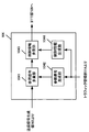
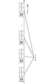
- FIG. 1 shows an example of a system configuration according to this embodiment.
- the system includes a base station apparatus 10 and terminal apparatuses 20-1 to 20-Nm.
- the number of terminal devices terminal, mobile terminal, mobile station, UE: “User” Equipment
- the base station apparatus 10 may perform communication using a so-called licensed band obtained from the country or region where the wireless provider provides the service, or use permission from the country or region. Communication using a so-called unlicensed band that is not required may be performed.
- the base station apparatus 10 may be a macro base station apparatus with a wide coverage, or a small cell base station or a pico base station apparatus (Pico ⁇ ⁇ ⁇ ⁇ ⁇ eNB: NBevolved Node B, SmallCell, Low Also called Power Node, Remote Radio Head).
- the frequency band other than the license band is not limited to the example of the unlicensed band, and may be a white band (white space) or the like.
- the base station apparatus 10 may apply a CA (Carrier Aggregation) technique that uses a plurality of component carriers (CC: Component Carrier or Serving cell) in a band used in LTE communication. Communication different from MTC may be transmitted by different CCs, or may be transmitted by the same CC.
- CA Carrier Aggregation
- communication different from MTC may be PCell (Primary cell) and MTC communication may be SCell (Secondary cell). Further, subcarriers (frequency), slots or subframes (time) to be used may be divided by communication and MTC different from MTC in the same CC.
- the terminal devices 20-1 to 20-Nm can transmit MTC data to the base station device 10.
- the terminal devices 20-1 to 20-Nm receive control information necessary for data transmission in advance from the base station device 10 or another base station device when connected to the base station.
- the terminal devices 20-1 to 20-Nm do not need to receive a scheduling request (SR: ulScheduling Request) transmission or transmission permission control information (UL Grant) transmitted by the base station device after transmission data (traffic) occurs.
- SR ulScheduling Request
- UL Grant transmission permission control information
- Wireless communication technology also called contention-based wireless communication technology, contention-based access, grant free access, grant free communication, grant free data transmission, grantless access, autonomous access, etc. Data transmission).
- the terminal devices 20-1 to 20-Nm are wireless communication technologies (non-contention based wireless communication) that require SR transmission such as LTE (Long Term Evolution), LTE-Advanced, LTE-Advanced Pro, and UL Grant reception.
- SR transmission such as LTE (Long Term Evolution), LTE-Advanced, LTE-Advanced Pro, and UL Grant reception.
- Technology, Grant-based access, Grant-based communication, Grant-based data transmission, Scheduled access, etc. (hereinafter referred to as non-contention based wireless communication technology)
- the contention-based wireless communication technology and the non-contention-based wireless communication technology may be switched and used according to the size, the quality of service (QoS: “Quality of Service”), and the like.
- QoS Quality of Service
- terminal apparatuses 20-1 to 20-Nm transmit data using radio resources scheduled from the base station apparatus by performing SR transmission before performing data transmission, or perform radio transmission designated in advance before data generation. It may be determined whether data is transmitted in at least a part of the resource.
- QoS may include data transmission reliability, delay time for data transmission, and communication speed, and power consumption for data transmission of the terminal device (for example, power per bit in data transmission). There may be indicators such as.
- the terminal devices 20-1 to 20-Nm are not limited to the MTC, and enable H2M communication (Human-to-Machine Communication) or H2H communication (Human-to-Human Communication) involving humans. Also good.
- the base station apparatus 10 uses UL scheduling, which is control information including transmission parameters used for data transmission by dynamic scheduling or SPS (Semi-Persistent Scheduling) depending on the type of data, as PDCCH (Physical Downlink Control CHannel) or EPDCCH. (Enhanced PDCCH) or other physical channel for transmitting downlink control information may be transmitted.
- UL scheduling which is control information including transmission parameters used for data transmission by dynamic scheduling or SPS (Semi-Persistent Scheduling) depending on the type of data, as PDCCH (Physical Downlink Control CHannel) or EPDCCH. (Enhanced PDCCH) or other physical channel for transmitting downlink control information may be transmitted.
- the terminal devices 20-1 to 20-Nm perform data transmission based on UL Grant transmission parameters.
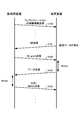
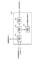
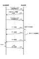
- FIG. 2 shows an example of a sequence chart of data transmission of a terminal device according to the conventional wireless communication technology.
- the base station device transmits configuration control information when the terminal device is connected (S100). Configuration control information may be notified by RRC (Radio Resource Control), upper layer control information such as SIB (System Information Block), or DCI format.
- RRC Radio Resource Control
- SIB System Information Block
- the physical channel to be used may be PDCCH, EPDCCH, PDSCH (Physical Downlink Shared CHannel), or other physical channels.
- the terminal device transmits SR to request UL Grant (S101). After receiving the SR, the base station apparatus transmits UL Grant to the terminal apparatus using PDCCH or EPDCCH (S102).
- the terminal device In the case of FDD (also referred to as Frequency Division Duplex or frame structure type 1), the terminal device is a subframe 4 msec after a subframe in which UL Grant is detected by blind decoding of PDCCH and EPDCCH, and is included in UL Grant. Data transmission based on the parameters is performed (S103).
- TDD also referred to as “Time Division Duplex” or “frame structure type 2”
- it is not limited to 4 msec, but will be described on the assumption of FDD in order to simplify the description.
- the base station apparatus detects data transmitted by the terminal apparatus, and transmits ACK / NACK indicating whether or not there is an error in the data detected in the subframe 4 msec after the subframe in which the data signal is received (S104).
- S101 when the resource for SR transmission is not notified by RRC, the terminal device requests UL Grant using PRACH (Physical Random Access CHannel).
- PRACH Physical Random Access CHannel
- S102 data transmission of only one subframe is possible in the case of dynamic scheduling, but periodic data transmission is permitted in the case of SPS, and information such as the SPS period is notified by the RRC of S100.
- the terminal device stores a transmission parameter such as an SR transmission resource notified by RRC from the base station device, an SPS cycle, and the like.
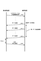
- FIG. 3 shows an example of a sequence chart of data transmission of the terminal device according to the wireless communication technology of the present embodiment.
- the base station apparatus transmits configuration control information when the terminal apparatus is connected (S200).
- the configuration control information may be notified by RRC, upper layer control information such as SIB, or DCI format.
- the physical channel to be used may be PDCCH, EPDCCH, PDSCH, or other physical channels.
- the configuration control information includes radio resources and transmission parameters used in the contention-based radio communication technology.
- the terminal device can also use a non-contention based wireless communication technology such as LTE, LTE-Advanced, LTE-Advanced Pro, etc.
- the control information notified in S100 of FIG. 2 may be included.
- the terminal device When uplink data is generated and the control information of S200 is received, the terminal device transmits data using contention-based wireless communication technology that does not require SR transmission or UL Grant transmission transmitted by the base station device. (S201-1).
- the terminal device is notified of the same data transmission count, transmission period, transmission cycle, radio resources used for transmission, transmission parameters, etc. in S200, and requested QoS (data transmission reliability, data transmission
- the same data as S201-1 is transmitted based on the control information received in S200 (S201-2 to S201-L).
- the base station apparatus detects the data transmitted by the terminal apparatus, and transmits ACK / NACK indicating whether or not there is an error in the data detected in the subframe Xmsec after the subframe receiving the data signal (S202).
- X may be set to 4 from data transmission or may be a different value.
- the last data transmission (S201-L) is used as a reference.
- the base station apparatus may use a subframe in which data can be detected without error as a reference after Xmsec. May stop the same data transmission when the terminal detects ACK / NACK.
- ACK / NACK may not be transmitted, and the base station apparatus may switch the transmission / non-transmission of ACK / NACK depending on the non-contention-based and contention-based wireless communication technology.
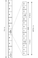
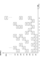
- FIG. 4 shows an example of an uplink frame configuration related to the conventional wireless communication technology.
- one frame is 10 msec, 10 subframes are configured, 1 subframe is configured by 2 slots, and 1 slot is configured by 7 OFDM symbols.
- DMRS De-Modulation Reference Signal
- OFDM symbol # 4 a demodulation reference signal
- FIG. 5 shows an example of an uplink frame configuration according to the wireless communication technique of this embodiment. This figure is an example in which the frame configuration is the same as in FIG.
- the terminal device can transmit data immediately after data is generated, and when data is generated before subframe # 1, data transmission shown in the example of FIG. 5 is performed. In subframe # 1, a transmission terminal identification signal is transmitted, and in subframe # 2, data is transmitted. Details of the transmission terminal identification signal and the data transmission method will be described later.
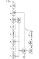
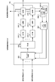
- FIG. 6 shows an example of the configuration of the terminal device according to the present embodiment.
- the terminal device is assumed to be able to use both the contention-based wireless communication technology and the above-described conventional non-contention-based wireless communication technology for MTC data transmission like the terminal devices 20-1 to 20-Nm.
- the present invention can also be applied when the terminal apparatus can use only the contention-based wireless communication technology. In this case, there is no processing related to the non-contention-based wireless communication technology, but the basic configuration is the same.
- the terminal apparatus receives control information transmitted from the base station apparatus via EPDCCH, PDCCH, and PDSCH by the reception antenna 110.
- the radio reception unit 111 down-converts the received signal to a baseband frequency, performs A / D (Analog / Digital: analog / digital) conversion, and removes a CP (Cyclic Prefix) from the digital signal.
- the control information detection unit 112 detects a DCI (Downlink Control Information) format addressed to the own station transmitted by PDCCH or EPDCCH by blind decoding. Blind decoding performs decoding processing on the candidate CSS (Common Search Space) or USS (UE-specific Search Space) in which the DCI format is placed, and cyclic redundancy check (CRC: Cyclic Redundancy added to the data signal) If it can be detected without error bits in (Check), it is detected as control information addressed to its own station.
- DCI Downlink Control Information
- the base station device can perform exclusive OR with C-RNTI (Cell-Radio Network Temporary Identifier) or SPS C-RNTI, which is an ID unique to the destination terminal device.
- C-RNTI Cell-Radio Network Temporary Identifier
- SPS C-RNTI SPS C-RNTI
- the terminal device performs an exclusive OR operation on the CRC and C-RNTI or SPS C-RNTI, and determines whether or not there is an error bit in the CRC of the operation result.
- DCI format a plurality of formats are defined according to the use, and DCI format 0 for uplink single antenna, DCI format 4 for MIMO (Multiple-Input-Multiple-Output), and the like are defined.
- the control information detection unit 112 also performs detection when an RRC signal is received.
- the control information detection unit 112 inputs the detected control information to the transmission parameter storage unit 113.
- the transmission parameter storage unit 113 inputs control information to the traffic management unit 114 when receiving UL Grant such as dynamic scheduling or SPS.
- the transmission parameter storage unit 113 retains the control information until data transmission is performed using the contention-based wireless communication technology.
- the configuration control information held by the transmission parameter storage unit 113 will be described later.
- the traffic management unit 114 receives a bit string of transmission data, receives control information when receiving UL Grant, and controls the configuration information for contention-based wireless communication technology in advance. Information is also entered. Further, the traffic management unit 114 may also input the type of transmission data, QoS, and the like. The traffic management unit 114 selects the use of contention-based or non-contention-based radio communication technology from the input information, and transmits the transmission parameters of the selected radio communication technology as an error correction coding unit 101, modulation unit 102, transmission The data is input to the signal generator 103, the signal multiplexer 104, and the identification signal generator 115, and the data bit string is input to the error correction encoder 101.
- the error correction encoding unit 101 encodes an error correction code on the input data bit string.
- the error correction code for example, a turbo code, an LDPC (Low Density Parity Check) code, a convolutional code, a Polar code, or the like is used.
- the type and coding rate of the error correction code performed by the error correction coding unit 101 may be determined in advance by the transmission / reception apparatus, may be input from the traffic management unit 114, or may be contention-based or non-coding. Switching may be performed by contention-based wireless communication technology. When the error correction coding type and coding rate are notified as control information, these pieces of information are input from the traffic management unit 114 to the error correction coding unit 101.
- the error correction encoding unit 101 may perform puncturing (decimation) and interleaving (rearrangement) of the encoded bit string in accordance with the applied coding rate.
- the error correction encoding unit 101 performs interleaving differently for each terminal device when interleaving the encoded bit string.
- the error correction coding unit 101 may apply scrambling.
- scramble may be applied only when the base station apparatus can uniquely determine the scramble pattern used by the terminal apparatus by an identification signal described later.
- a spread code may be used for coded bits obtained by error correction coding. Spread codes may be used at all coding rates used in data transmission, or spread codes may be used only at specific coding rates.
- An example of using a spreading code only for a specific coding rate is only when data is transmitted at a coding rate lower than the coding rate for transmitting all of the coded bits obtained by error correction coding (even if it is a turbo code). For example, only below 1/3), a spreading code is used. Even if switching is performed such as using a spread code when transmitting data with a low coding rate using contention-based wireless communication technology and not using a spread code when transmitting data with a low coding rate using non-contention-based wireless communication technology. good.
- the modulation unit 102 receives the modulation scheme information from the traffic management unit 114 and modulates the encoded bit sequence input from the error correction encoding unit 101 to generate a modulation symbol sequence.
- the modulation method include QPSK (Quaternary Phase Shift Keying), 16 QAM (16-ary Quadrature Amplitude Modulation) 64 QAM, and 256 QAM.
- the modulation method may not be Gray labeling, and set partitioning may be used. Further, GMSK (Gaussian Minimum-Shift ⁇ Keying) may be used.
- Modulation section 102 outputs the generated modulation symbol sequence to transmission signal generation section 103.
- the modulation method or modulation method may be determined in advance by the transmission / reception device, may be input from the traffic management unit 114, or may be switched by a contention-based or non-contention-based wireless communication technology. good.
- a spreading code may be used. This means that the spread code is not applied to the encoded bit string after the error correction encoding but applied to the modulation symbol string. All modulation multi-level numbers (number of bits included in one modulation symbol) used for data transmission or spreading codes may be used at the coding rate, or all MCS (Modulation and Coding Scheme) (Spread code) may be used, or a spread code may be used with a specific modulation multilevel number, a specific coding rate, or a specific MCS.
- MCS Modulation and Coding Scheme
- An example of using a spreading code with a specific modulation multi-level number uses a spreading code only during BPSK or QPSK data transmission.
- An example of using a spreading code at a specific coding rate is only when data is transmitted at a coding rate lower than the coding rate for transmitting all of the coded bits obtained by error correction coding (even if it is a turbo code). (Only if less than 1/3) spread code is used.
- An example of using a spreading code in a specific MCS is only when data is transmitted at a coding rate lower than the coding rate in the case of transmitting all of the coded bits obtained by BPSK, QPSK and error correction coding (turbo code). (Only if less than 1/3) spread code is used.
- switching may be performed such that a spread code is used at the time of data transmission at a low coding rate by the contention-based wireless communication technology and a spread code is not used at the time of data transmission by the non-contention-based wireless communication technology.
- the DFT unit 1031 performs discrete Fourier transform on the input modulation symbol, thereby converting the time domain signal into the frequency domain signal, and outputs the obtained frequency domain signal to the signal allocation unit 1032.
- the signal allocation unit 1032 receives resource allocation information, which is information of one or more RBs (Resource Block) used for data transmission, from the traffic management unit 114, and allocates a frequency domain transmission signal to the designated RB.
- the resource allocation information input from the traffic management unit 114 is notified by UL Grant in the case of non-contention based wireless communication technology, and is notified in advance by configuration control information in the case of contention based wireless communication technology. .
- 1 RB is defined by 12 subcarriers and 1 slot (7 OFDM symbol), and the resource allocation information is information for allocating 1 subframe (2 slots).
- 1 subframe is 1 msec and the subcarrier interval is 15 kHz, but the time and subcarrier interval of 1 subframe is 4 msec, 3.75 kHz, 2 msec, 7.5 kHz, 0.2 msec, 75 kHz or , 0.1 msec, 150 kHz, etc.
- resource allocation information may be notified in units of one subframe even in different frame configurations.
- the resource allocation information may notify the allocation of a plurality of subframes regardless of whether it is the same as the LTE subframe configuration or different from the LTE subframe configuration.
- Notification may be sent, allocation in units of OFDM symbols may be notified, or allocation in units of a plurality of OFDM symbols such as 2 OFDM symbols may be notified.
- the resource allocation information may be in units of one subcarrier, not in units of RBs, in units of RBGs (Resource Block Group) composed of a plurality of RBs, and may be allocated to one or more RBGs.
- the resource allocation information is not limited to continuous RBs or continuous subcarriers, but may be discontinuous RBs or discontinuous subcarriers.
- the terminal apparatus may use only a part of the RB or subcarrier indicated by the resource allocation information for data transmission. In this case, the base station apparatus needs to notify the information of the RB and subcarrier used by the terminal apparatus for data transmission in advance or be able to detect from other signals.
- phase rotation section 1030 performs phase rotation on the input modulation symbol.
- the phase rotation applied to the time domain data signal in the phase rotation unit 1030 uses a pattern input from the traffic management unit 114 in order to apply a different pattern for each terminal device.
- An example of the phase rotation pattern is a pattern in which the phase rotation is different for each modulation symbol. It is assumed that the phase rotation pattern input by the traffic management unit 114 is shared between the terminal device and the base station device by being notified by UL Grant or by being notified in advance by configuration control information.
- the DFT unit 1031 and the signal allocation unit 1032 are the same as those in FIG. Here, FIG.
- a different cyclic delay may be given to the frequency domain signal obtained by the DFT unit 1031 for each terminal device.
- the frequency domain signal of the terminal device 20-u that is not cyclically delayed is S U (1), S U (2), S U (3), S U (4)
- the terminal device 20- A cyclic delay having a delay amount of 1 symbol is given to i
- S i (4), S i (1), S i (2), S i (3) are set.
- the DFT unit 1031 and the signal allocation unit 1032 in FIG. 9 are the same as those in FIG.
- the phase rotation unit 1033 performs phase rotation on the frequency domain data signal obtained by the DFT unit 1031.
- the phase rotation applied to the frequency domain data signal in the phase rotation unit 1033 uses a pattern input from the traffic management unit 114 in order to apply a different pattern for each terminal device.
- An example of the phase rotation pattern is a different phase rotation for each data signal unit (subcarrier unit) in the frequency domain.
- the phase rotation pattern input by the traffic management unit 114 is assumed to be information shared between the terminal apparatus and the base station apparatus, for example, notified by UL Grant or previously notified by configuration control information.
- the DFT unit 1031 may give different cyclic delays to the modulation symbols before conversion into frequency domain signals for each terminal apparatus. Specifically, when the time domain signal of the terminal device 20-u that does not have a cyclic delay is s U (1), s U (2), s U (3), and s U (4), the terminal device 20- A cyclic delay having a delay amount of 1 is given to i to make s i (4), s i (1), s i (2), s i (3), and so on. Further, both the phase rotation unit 1030 and the phase rotation unit 1033 of FIGS. 8 and 9 may be used.
- the transmission signal generation unit 103 in FIGS. 7 to 9 inputs the transmission signal to the signal multiplexing unit 104.
- the configuration of the transmission signal generation unit 103 may be the configuration of FIG.
- the transmission signal generation unit 103 performs interleaving (rearrangement) on the modulation symbols input before the DFT unit 1031.
- interleaving is performed on the modulation symbols
- different interleaving is performed for each terminal apparatus. It is not limited to the example of using interleaving different for each terminal device shown in FIG. 10, but using interleaving different for each terminal device with respect to the encoded bit string obtained from the error correction coding unit 101. Also good.
- interleaving that is different for each terminal apparatus after applying the spreading code may be used, or different for each terminal apparatus before the spreading code is applied. Interleaving may be used.
- FIG. 11 shows an example of the configuration of the signal multiplexing unit 104 according to the present embodiment.
- the transmission signal input from the transmission signal generation unit 103 is input to the reference signal multiplexing unit 1041.
- the traffic management unit 114 inputs a parameter for generating a reference signal to the reference signal generation unit 1042, and inputs control information to be transmitted to the base station apparatus to the control information generation unit 1044.
- the reference signal multiplexing unit 1041 multiplexes the input transmission signal and the reference signal sequence (DMRS) generated by the reference signal generation unit.
- DMRS reference signal sequence
- the frame structure shown in FIG. 4 is generated by multiplexing the transmission signal and DMRS.
- the frame configuration in FIG. 5 will be described later.
- the reference signal multiplexing section 1041 may multiplex the data signal and the reference signal in the time domain when arranged in an OFDM symbol different from the data signal as in the frame configuration of FIG.
- control information generation unit 1044 transmits channel quality information (CSI: Channel State Information), SR (Scheduling Request), and ACK / NACK (Acknowledgement / Negative) of uplink control information transmitted by PUCCH (Physical Uplink Control CHannel). Acknowledgment) is generated and output to the control information multiplexing unit 1043.
- the control information multiplexing unit 1043 multiplexes control information for a frame configuration composed of a data signal and a reference signal.
- the signal multiplexing unit 104 inputs the generated transmission frame to the IFFT unit 105.
- the terminal device cannot perform simultaneous transmission of PUSCH and PUCCH (when there is no Capability for simultaneous transmission), only a signal with a high priority is transmitted according to a predetermined signal priority.
- the terminal device can simultaneously transmit PUSCH and PUCCH (when there is Capability of simultaneous transmission) (when there is Capability of simultaneous transmission)
- Only signals with high priority are transmitted according to the priority order of the signals.
- the signal transmission priority may be different between the contention-based wireless communication technology and the non-contention-based wireless communication technology.
- priority exists in the data to transmit, and the priority of PUSCH may change with the priority.
- the IFFT unit 105 receives a frequency-domain transmission frame and performs inverse fast Fourier transform on each OFDM symbol unit to convert the frequency-domain signal sequence into a time-domain signal sequence.
- IFFT unit 105 inputs the time domain signal sequence to identification signal multiplexing unit 106.
- the identification signal generation unit 115 generates a signal to be transmitted in the identification signal subframe of FIG. 5 and inputs the signal to the identification signal multiplexing unit 106. Details of the identification signal will be described later.
- Identification signal multiplexing section 106 multiplexes the time domain signal sequence and the identification signal into different subframes as shown in FIG. 5 and inputs the multiplexed signal to transmission power control section 107.
- the transmission power control unit 107 performs transmission power control using only the open loop transmission power control value or both the open loop and closed loop transmission power control values, and transmits the signal sequence after the transmission power control to the transmission processing unit 108.
- the transmission processing unit 108 inserts a CP into the input signal sequence, converts it into an analog signal by D / A (Digital / Analog) conversion, and converts the converted signal to a radio frequency used for transmission. Up-convert.
- the transmission processing unit 108 amplifies the up-converted signal with PA (Power-Amplifier), and transmits the amplified signal via the transmission antenna 109.
- PA Power-Amplifier
- the terminal device performs data transmission.
- a DFTS-OFDM also called Discrete Fourier Transform Spread Orthogonal Frequency Division Multiplexing, SC-FDMA
- SC-FDMA Discrete Fourier Transform Spread Orthogonal Frequency Division Multiplexing
- the terminal apparatus does not perform DFT in the transmission signal generation unit 103, that is, in a configuration in which the DFT unit 1031 does not exist in any of FIGS. 7 to 10, it means that the OFDM signal is transmitted.
- the terminal device may use the above-described method in the transmission signal generation unit 103, or may use a different spreading method or a different transmission signal waveform generation method.
- FIG. 12 shows an example of the configuration of the base station apparatus according to this embodiment.
- the base station apparatus receives data transmitted from the terminal apparatus through N reception antennas 201-1 to 201-N and inputs the data to the reception processing sections 202-1 to 202-N, respectively.
- Reception processing sections 202-1 to 202-N downconvert the received signal to a baseband frequency, perform A / D conversion, and remove the CP from the digital signal.
- Reception processing sections 202-1 to 202-N output signals after CP removal to identification signal separation sections 203-1 to 203-N.
- Identification signal separation sections 203-1 to 203-N separate the identification signal and other signals and output them to transmitting terminal identification section 211 and FFT sections 204-1 to 204-N, respectively.
- Transmitting terminal identifying section 211 identifies a terminal apparatus that has transmitted data from an identification signal described later, and outputs information on the transmitting terminal apparatus to propagation path estimating section 207 and signal demultiplexing sections 205-1 to 205-N.
- the FFT units 204-1 to 204-N convert the input received signal sequence from a time domain signal sequence to a frequency domain signal sequence by fast Fourier transform, and the frequency domain signal sequence is converted to signal separation units 205-1 to 205-N. Output to.
- the signal separators 205-1 to 205-N all have a common configuration, and FIG. 13 shows an example of the configuration of the signal separator 205-1 according to the present embodiment.
- the frequency domain signal sequence is input from the FFT unit 204-1 to the reference signal demultiplexing unit 2051, and the information of the transmitting terminal device identified by the transmitting terminal identifying unit 211 is input.
- the reference signal demultiplexing unit 2051 demultiplexes the frequency domain signal sequence into a reference signal and other signals using the input information of the transmitting terminal apparatus, and outputs them to the channel estimation unit 207 and the control information demultiplexing unit 2052, respectively.
- the control information separation unit 2052 separates the input signal into a control signal and a data signal, and outputs them to the control information detection unit 2054 and the allocation signal extraction unit 2053, respectively.
- the control information detection unit 2054 detects a signal transmitted on the PUCCH. Since the SR is used for uplink scheduling, the CSI is used for downlink scheduling, and the ACK / NACK is used for retransmission control of downlink transmission, the control information generation unit 208 is used. Output to.
- the allocation signal extraction unit 2053 extracts a transmission signal for each terminal device based on the resource allocation information notified to the terminal device by the control information.
- the propagation path estimation unit 207 receives information of a transmission terminal apparatus identified as DMRS (De-Modulation Reference Signal) which is a reference signal multiplexed and transmitted with a data signal, estimates a frequency response, and performs demodulation. The estimated frequency response is output to the signal detection unit 206. Moreover, the propagation path estimation part 207 estimates the frequency response used by the next scheduling, when SRS (Sounding * Reference * Signal) is input.
- the control information generation unit 208 performs uplink scheduling and adaptive modulation and coding (also called adaptive modulation and coding, also called link adaptation) based on the frequency response estimated by DMRS or SRS, and the terminal device performs uplink transmission. A transmission parameter to be used is generated and converted into a DCI format.
- Control information generation section 208 generates control information for reporting ACK / NACK in uplink transmission when information on whether there is an error in the received data signal is input from signal detection section 206.
- ACK / NACK in uplink transmission is transmitted by PHICH (PhysicalICHARQ CHannel) or at least one of PDCCH and EPDCCH.
- the control information transmission unit 209 receives the control information converted from the control information generation unit 208, assigns the input control information to the PDCCH and the EPDCCH, and transmits the control information to each terminal device.
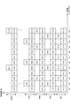
- FIG. 14 shows an example of the configuration of the signal detection unit 206 according to the present embodiment.
- the signal for each terminal device extracted from the signal separation units 205-1 to 205-N is input to the cancellation processing unit 2061.
- the cancel processing unit 2061 receives the soft replica from the soft replica generation unit 2067 and performs a cancel process on each received signal.
- the equalization unit 2062 generates an equalization weight based on the MMSE standard from the frequency response input from the propagation path estimation unit 207, and multiplies the signal after the soft cancellation.
- the equalization unit 2062 outputs the signal for each terminal device after equalization to the IDFT units 2063-1 to 2063-U.
- IDFT sections 2063-1 to 2063-U convert the received signal after frequency domain equalization into a time domain signal. If the terminal device performs cyclic delay, phase rotation, or interleaving on the signal before or after DFT in the transmission process, the cyclic delay, phase rotation, or interleaving is applied to the received signal or time domain signal after frequency domain equalization. Processing to restore is performed.
- the demodulation units 2064-1 to 2064-U receive information of a modulation scheme that has been notified in advance or is determined in advance, and performs demodulation processing on the received signal sequence in the time domain, A bit sequence LLR (Log Likelihood Ratio), that is, an LLR sequence is obtained.
- LLR Log Likelihood Ratio
- decoding units 2065-1 to 2065-U receive information of a coding rate that is notified in advance or is determined in advance, and performs decoding processing on the LLR sequence.
- decoding sections 2065-1 to 2065-U are decoders
- the output external LLR or posterior LLR is output to the symbol replica generation units 2066-1 to 2066-U.
- the difference between the external LLR and the posterior LLR is whether or not the prior LLR input to the decoding units 2065-1 to 2065-U is subtracted from the decoded LLR.
- the signal detection unit 206 inputs the decoding unit 2065-1 to 2065-U. Depuncturing (inserting 0 into the LLR of the thinned bits), deinterleaving (reverting the rearrangement), and descrambling are performed on the LLR sequence.
- the symbol replica generation units 2066-1 to 2066-U generate symbol replicas according to the modulation scheme used by the terminal apparatus for data transmission from the input LLR sequence, and output the symbol replicas to the soft replica generation unit 2067.
- the soft replica generation unit 2067 converts the input symbol replica into a frequency domain signal by DFT, and generates a soft replica by multiplying the frequency response.
- the decoding units 2065-1 to 2065-U make a hard decision on the decoded LLR sequence and perform a cyclic redundancy check (CRC: Cyclic Redundancy) From Check), the presence / absence of error bits is determined, and information on the presence / absence of error bits is output to the control information generation unit 208.
- CRC Cyclic Redundancy
- Symbol replica generation sections 2066-1 to 2066-U generate symbol replicas according to the spreading code and modulation scheme used by the terminal apparatus.
- FIG. 15 shows an example of the configuration of the identification signal of the transmission terminal apparatus according to this embodiment.
- the number of OFDM symbols that can be used for transmitting the identification signal is N OFDM
- the number of subcarriers that can be used for transmitting the identification signal is N SC .
- an OCC sequence having a length T OCC is used.
- the OCC sequence length is a value of 1 ⁇ T OCC ⁇ T OFDM , and it is only necessary that information on the OCC sequence length used between the transmitting and receiving apparatuses can be shared in advance.
- the number of subcarriers each transmission terminal device uses the transmission of the identification signal and T SC.
- T SC Cyclic Shift
- CS pattern number T CS when using the IFDMA (Interleaved Frequency Division Multiple Access) uses a multiple number of patterns T RF. Therefore, the number of orthogonal resources for the identification signal is (N OFDM / T OFDM ) ⁇ T OCC ⁇ (N SC / T SC ) ⁇ T CS ⁇ T RF .
- the configuration control information transmitted by the base station apparatus includes information indicating the orthogonal resource for transmitting the identification signal.
- the 2OFDM symbol to transmit an identification signal defines the OFDM symbol set as T1 ⁇ T7 every 2OFDM successive symbols as in FIG.
- an index I T of the OFDM symbol sets to be actually used there in N SC> T SC
- the information of the subcarrier set is X number of field use is defined as F1 ⁇ FX
- an index I F of the sub-carrier set to be actually used the index of the OCC sequences used as I OCC, the CS pattern used I and CS, multiple patterns of IFDMA used to I RF.
- the control information of the configuration of the base station apparatus transmits (I T, I F, I OCC, I CS, I RF) contains information uniquely indicating the.
- the configuration control information may be information including only a part of (I T , I F , I OCC , I CS , I RF ).
- the OFDM symbol set does not need to be a continuous OFDM symbol, and may be a combination such as OFDM symbol # 1 and OFDM symbol # 8. Also, may not be a sub-carrier also continuous in the sub-carrier set, for example, may be used in a non-continuous on the frequency axis a cluster of a plurality of identification signals is an integral multiple of T RF as a cluster identification signal. Further, the subcarriers S # 1 to S # N SC that can be used for transmitting the identification signal may be the same as or different from the subcarriers that transmit data. When the subcarrier that can be used for transmitting the identification signal is different from the subcarrier that transmits data, the identification signal and the subcarrier that transmits the data signal may partially overlap.
- the number of terminal devices accommodated in the base station device exceeds the number of orthogonal resources of the identification signal, it is necessary to assign the same orthogonal resource to different terminal devices in duplicate.
- the orthogonal resource of the identification signal it is necessary to identify the transmission terminal device by an identifier unique to the terminal device. Specifically, an exclusive OR operation is performed on the CRC added to the data signal using a C-RNTI (Cell-Radio Network Temporary Identifier) which is an ID unique to the terminal device, SPS C-RNTI, or the like.
- C-RNTI Cell-Radio Network Temporary Identifier
- the receiving base station apparatus performs an exclusive OR operation of a plurality of identifiers and CRC after signal detection by SIC, PIC, or turbo equalization, and confirms an identifier in which no error is detected by CRC.
- the transmission terminal device can be identified.
- FIG. 16 shows an example of frequency resources used for uplink data transmission according to the present embodiment.
- the figure shows an example in which different frequency resources are used for each terminal device with respect to frequency resources that can be used for data transmission of contention-based radio access technology.
- the frequency index on the horizontal axis is a subcarrier number
- S (u, i) indicates the i-th frequency domain signal of UE # u.
- UE # 1 uses all available subcarriers and transmits data using a DFTS-OFDM signal
- UEs # 2 to # 8 transmit DFTS-OFDM signals in a discontinuous and equally spaced subcarrier.
- This is an example of transmitting data using.
- PAPR Peak-to-Average-Power-Ratio
- the frequency resource which can be used for data transmission of contention-based radio access technology has been described as 12 subcarriers, the present invention is not limited to this example, and a plurality of 12 subcarriers can be used as one access region.
- the access area may be prepared. For example, by accommodating different terminal devices in each access region, it is possible to accommodate the number of terminal devices that is X times Nm by preparing X access regions.
- the frequency index on the horizontal axis in FIG. 16 is not limited to the subcarrier number, and may be an RB number or an RBG number.
- FIG. 17 shows an example of frequency resources used for uplink data transmission according to the present embodiment.
- the figure shows that DFTS-OFDM signals are continuous subcarriers or discontinuous for some frequency resources for subcarrier indexes # 1 to # 12 that can be used for content-based radio access technology data transmission.
- data is allocated to subcarriers that are equally spaced and transmitted.
- the subcarrier index is divided into # 1 to # 6 and # 7 to # 12.
- different division methods may be used.
- the subcarrier to be used may be divided into three or more and used together with frequency division multiplexing.
- the frequency resource which can be used for data transmission of contention-based radio access technology has been described as 12 subcarriers, the present invention is not limited to this example, and a plurality of 12 subcarriers can be used as one access region.
- the access area may be prepared. For example, by accommodating different terminal devices in each access region, it is possible to accommodate the number of terminal devices that is X times Nm by preparing X access regions.
- the frequency index on the horizontal axis in FIG. 17 is not limited to the subcarrier number, and may be an RB number or an RBG number.
- FIG. 18 shows an example of frequency resources used for uplink data transmission according to the present embodiment.
- This figure shows that DFTS-OFDM signals are transmitted to continuous subcarriers or subcarriers that are not discontinuous at regular intervals for subcarrier indexes # 1 to # 12 that can be used for content-based radio access technology data transmission. It is an example which allocates and transmits.
- a variety of subcarrier usage methods are possible. Therefore, when different frequency resources are used for each terminal device, more frequency resource allocation patterns can be prepared, and the number of terminal devices that can be accommodated can be greatly increased.
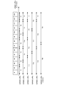
- FIG. 19 shows an example of frequency resources used for uplink data transmission and identification signal transmission according to this embodiment.
- This figure shows the identification signal of the i-th frequency domain of UE #u, with subcarrier indexes # 1 to # 12 that can be used for data transmission of contention-based radio access technology.
- DFTS-OFDM signals are allocated to subcarriers # 1 to # 12 and transmitted by assigning data to continuous subcarriers or subcarriers that are discontinuous and equally spaced. In this case, even if a plurality of terminal apparatuses transmit data in the same subframe, collision occurs only with some frequency resources, and DMRS orthogonalization becomes a problem.
- orthogonalization is realized by CS on the premise that a plurality of data signals collide (multiplex) with the same frequency resource in single user MIMO, multiuser MIMO, or the like.
- orthogonalization by CS cannot be performed, and orthogonalization is performed only by OCC having a sequence length of 2, and the number of terminal devices that can be accommodated is 2. It will be limited to. Therefore, the example of FIG. 19 shares the identification signal and DMRS. That is, in order to realize propagation path estimation using the identification signal, data is arranged without performing DMRS transmission in OFDM symbols # 4 and # 11 in the data transmission subframe (UL transmission subframe) in the frame configuration of FIG. .
- the reference signal multiplexing unit 1041 and the reference signal generation unit 1042 generate DMRS and multiplex the data signal.
- the reference signal multiplexing unit 1041 is shared with the identification signal and DMRS.
- the reference signal generation unit 1042 does nothing.
- the reference signal multiplexing unit 1041 and the reference signal generating unit 1042 generate DMRS and data signals when transmitting data using the non-contention based wireless communication technology. Perform multiplexing.
- the reference signal separation unit 2051 separates the DMRS, but the contention-based wireless communication technique does nothing because the identification signal and the DMRS are shared. However, when the terminal device also uses a non-contention based wireless communication technology, the reference signal separation unit 2051 separates the DMRS at the time of data transmission using the non-contention based wireless communication technology.
- the identification signal uses a subcarrier different from the subcarrier to which the data signal is allocated. Specifically, the identification signal uses all of the subcarriers # 1 to # 12 that can be used for data transmission of contention-based radio access technology, and the data signal is a part of UE # 2 to Nm in FIG. Only subcarriers are used. As shown in FIG. 19, when the subcarriers used for transmitting the identification signal match between UEs # 1 to Nm, orthogonalization in CS is possible, and the number of terminal devices that can be accommodated can be increased.
- the frequency resource which can be used for data transmission of contention-based radio access technology has been described as 12 subcarriers, the present invention is not limited to this example, and a plurality of 12 subcarriers can be used as one access region.
- the access area may be prepared. For example, by accommodating different terminal devices in each access region, it is possible to accommodate the number of terminal devices that is X times Nm by preparing X access regions.
- the frequency index on the horizontal axis in FIG. 19 is not limited to the subcarrier number, but may be an RB number or an RBG number.
- the example of FIG. 19 shows an example in which the number of subcarriers used for transmitting the identification signal is larger than the number of subcarriers used for data transmission.
- the number of subcarriers used for the identification signal may be less than the number of subcarriers used.
- the subcarrier is divided into # 1 to # 6 and # 7 to 12, and the terminal apparatus uses only # 1 to 6 or # 7 to 12 as the subcarrier used for transmitting the identification signal.
- the number of subcarriers used for an identification signal becomes smaller than the number of subcarriers used for data transmission.
- the subcarrier used by the terminal device for transmitting the identification signal may be determined by assigning a subcarrier for transmitting data. For example, when data transmission is performed using subcarriers such as UE # 5 in FIG. 18, since the number of subcarriers for data transmission is larger in subcarriers # 7 to 12 than in subcarriers # 1 to 6, identification is performed. The signal may be transmitted on subcarriers # 7 to # 12.
- the contention-based wireless communication technology even if multiple terminal devices transmit data in the same subframe by using different frequency resources for each terminal device, some frequencies are used. Collisions are made only with resources, and the amount of interference is reduced.
- PAPR characteristics are improved as compared with signal allocation at non-equal intervals. As a result, it is possible to improve the reception quality and the frequency utilization efficiency of the entire system, and to accommodate a large number of terminals efficiently.
- the configuration example of the terminal device is the same as that of the first embodiment, and is FIG. 6, 7, 8, 9, 10, 11.
- the configuration example of the base station device is also the same as that of the first embodiment. 12, 13, and 14.
- the sequence chart of data transmission of the terminal device is also the same as that in the first embodiment and is shown in FIG. Therefore, in the present embodiment, only different processing will be described, and description of similar processing will be omitted.
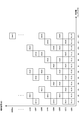
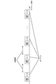
- FIG. 20 shows an example of uplink identification signals and data transmission according to this embodiment. This embodiment is an example in which the same data is transmitted a plurality of times, and shows a case where an identification signal and data are transmitted at each transmission opportunity.
- the terminal device transmits data using the contention-based wireless access technology, the data transmission unit in one subframe shown in FIG.
- Transmission sections T1 to T7 are cases where data is transmitted using only 2 OFDM symbols within one subframe
- transmission sections T8 to 11 are cases where data is transmitted using only 3 OFDM symbols within one subframe
- transmission sections T12 to 15 are This is a case where data is transmitted only with 4 OFDM symbols within one subframe
- transmission intervals T16 to 17 are cases where data is transmitted with only 5 OFDM symbols within one subframe
- transmission intervals T18 to 19 are 6 OFDM within one subframe.
- transmission sections T20 to T21 are cases where data is transmitted with only 7 OFDM symbols (1 slot) in one subframe.
- the terminal apparatus may change the transmission interval for each data transmission in the number of OFDM symbols used for data transmission.
- the subframe number for data transmission is 1 ⁇ Nf ⁇ 10
- the number of selectable transmission sections is Nd
- the transmission section offset given for each terminal device is 0 ⁇ Noff ⁇ Nd ⁇ 1
- the amount of hopping in the transmission section Where 0 ⁇ Nh ⁇ Nd ⁇ 1, it can be calculated by mod (Nf ⁇ Nh + Noff, Nd) +1.
- the probability of collision at the same frequency and the same time may be reduced by changing the frequency resource used for each data transmission. That is, the frequency resource to be used in association with the subframe number for transmitting data of the same data may be changed. For example, the allocation of the frequency resource to be used may be changed according to the subframe number at the time of data transmission as shown in FIG. If the data size to be transmitted is very small, it may be applied to data transmission simultaneously with some OFDM symbols in one subframe (the number of OFDM symbols to be used is 13 or less). When using frequency resources, data is transmitted in slot units or OFDM symbol units in a subframe. In addition, frequency resources and time resources (slot numbers and OFDM symbols) may be changed according to subframe numbers and slot numbers during retransmission.
- the identification signal in FIG. 20 and the number of subframes for transmitting data need not be the same, and the subframe for transmitting data for one subframe for transmitting the identification signal as in the example of FIG. Two may be used.
- the overhead may be reduced by increasing the number of subframes in which data transmission is possible.
- the present invention is not limited to this example.
- the subframe of the present embodiment is used.
- the time / frequency resource for data transmission may be changed depending on the number.
- the invention is not limited to this example.
- the orthogonal resource of the identification signal, the DMRS sequence, and the orthogonal resource The time / frequency resource for data transmission may be changed in association with.
- the present invention can also be applied to cases where the transmission interval in one subframe is different for each terminal device or the number of frequency resources used for data transmission is different for each terminal device.
- predicted traffic information such as the frequency of occurrence of data specific to the terminal device and the predicted data amount is transmitted, and the configuration control information is transmitted based on the predicted traffic information received by the base station device.
- the configuration control information is transmitted based on the predicted traffic information received by the base station device.
- FIG. 23 shows a sequence chart of data transmission of the terminal device.
- the base station apparatus transmits control information of a configuration that does not change depending on the state and capability of the terminal apparatus and QoS (S300). For example, there are transmission / non-transmission of CSI, transmission / non-transmission of DMRS in the data transmission subframe, transmission / non-transmission of SRS, and the like.
- the terminal device transmits predicted traffic information (S301).
- the predicted traffic information includes the frequency of occurrence of the predicted data (average occurrence cycle), the amount of transmission data (average value of the predicted data amount, maximum value, etc.), required data rate, and reception quality (required Packet error rate).
- the terminal device may transmit Capability and UE category together with the predicted traffic information. Capability includes information on whether HARQ can be used, information on whether a closed loop control value for transmission power control can be used, information on whether fractional transmission power control can be used, information on whether SRS can be transmitted, and the number of transmission / reception antennas Or information on the number of antennas that can be used simultaneously.
- the UE category includes a data rate (data rate that can be transmitted) supported by the terminal device, a buffer size, and the like.
- the terminal device may transmit the predicted traffic information a plurality of times instead of only once at the initial connection or handover.
- the predicted traffic information may be transmitted when a change occurs from the predicted traffic information transmitted by the terminal device.
- information on predicted traffic may be transmitted when a predetermined change amount is determined in advance and the occurrence frequency of predicted data or the amount of transmission data increases or decreases beyond a predetermined change amount.
- the terminal device may periodically transmit the predicted traffic information.
- the base station device After receiving the predicted traffic information from the terminal device, the base station device transmits configuration control information corresponding to the received information (S302). For example, there are frequency resources (frequency position, bandwidth), MCS (Modulation and Coding Scheme), cell-specific and terminal device-specific target reception, and the like.
- the terminal device has a plurality of transmission antennas, the number of transmission layers (number of ranks), MCS for each layer (or for each codeword), and precoding information may also be included.
- steps S201-1 to S202 in FIG. 3 are the same as those in FIG.
- the frequency resource (frequency position, bandwidth) included in the configuration control information transmitted from the base station device based on the predicted traffic information may be determined for each terminal device. That is, the base station apparatus may prepare a plurality of access areas (frequency positions and bandwidths) in which the terminal apparatus is accommodated by contention-based wireless communication technology, or may specify a different access area for each terminal apparatus. As a method for determining an access area to be notified to each terminal apparatus, terminal apparatuses having the same amount of transmission data, a required data rate, and transmission quality may be made the same access area. Further, the base station apparatus may transmit the configuration control information so that the terminal apparatuses accommodated in the same access area use the same MCS for data transmission. In this case, when it is necessary to change the MCS based on the predicted traffic information of the terminal device, the configuration control information may be transmitted again, and the access area may be changed simultaneously with the change of the MCS.
- the terminal device may transmit the transmission power reserve (PH: Power Headroom) simultaneously or periodically with the predicted traffic information.
- the base station apparatus may set the MCS according to the PH.
- the base station apparatus may transmit configuration control information for changing the MCS and the access area when the PH transmitted from the terminal apparatus changes significantly compared to the previous PH.
- DMRS sequences and orthogonal resources may be associated with a coding rate and notified.
- the base station device controls the access region, MCS, and the like based on the predicted traffic information transmitted by the terminal device, so that efficient contention-based Wireless communication can be realized.
- MCS mobility-based channel control
- the base station device controls the access region, MCS, and the like based on the predicted traffic information transmitted by the terminal device, so that efficient contention-based Wireless communication can be realized.
- it is possible to improve the reception quality and the frequency utilization efficiency of the entire system, and to accommodate a large number of terminals efficiently.
- the program that operates on the device related to the present invention may be a program that controls the central processing unit (CPU) and the like to function the computer so as to realize the functions of the embodiments related to the present invention.
- the program or information handled by the program is temporarily stored in a volatile memory such as Random Access Memory (RAM), a non-volatile memory such as a flash memory, a Hard Disk Drive (HDD), or other storage system.
- RAM Random Access Memory
- HDD Hard Disk Drive
- a program for realizing the functions of the embodiments according to the present invention may be recorded on a computer-readable recording medium.
- the “computer system” here is a computer system built in the apparatus, and includes hardware such as an operating system and peripheral devices.
- the “computer-readable recording medium” refers to a semiconductor recording medium, an optical recording medium, a magnetic recording medium, a medium that dynamically holds a program for a short time, or other recording medium that can be read by a computer. Also good.
- each functional block or various features of the apparatus used in the above-described embodiments can be implemented or executed by an electric circuit, for example, an integrated circuit or a plurality of integrated circuits.
- Electrical circuits designed to perform the functions described herein can be general purpose processors, digital signal processors (DSPs), application specific integrated circuits (ASICs), field programmable gate arrays (FPGAs), or other Programmable logic devices, discrete gate or transistor logic, discrete hardware components, or combinations thereof.
- a general purpose processor may be a microprocessor or a conventional processor, controller, microcontroller, or state machine.
- the electric circuit described above may be configured with a digital circuit or an analog circuit. Further, in the case where an integrated circuit technology that replaces the current integrated circuit appears due to the progress of semiconductor technology, the present invention can also use a new integrated circuit based on the technology.
- the present invention is not limited to the above-described embodiment.
- an example of the apparatus has been described.
- the present invention is not limited to this, and a stationary or non-movable electronic device installed indoors or outdoors, such as an AV device, a kitchen device, It can be applied to terminal devices or communication devices such as cleaning / washing equipment, air conditioning equipment, office equipment, vending machines, and other daily life equipment.
- DESCRIPTION OF SYMBOLS 10 Base station apparatus 20-1 to 20-Nm ... Terminal apparatus 101 ... Error correction encoding part 102 ... Modulation part 103 ... Transmission signal generation part 104 ... Signal multiplexing part 105 ... IFFT part 106 ... Identification signal multiplexing part 107 ... Transmission Power control unit 108 ... transmission processing unit 109 ... transmission antenna 110 ... reception antenna 111 ... radio reception unit 112 ... control information detection unit 113 ... transmission parameter storage unit 114 ... traffic management unit 1030 ... phase rotation unit 1031 ... DFT unit 1032 ... signal Allocation unit 1033 ... Phase rotation unit 1034 ... Interleaving unit 1041 ... Reference signal multiplexing unit 1042 ...
- Reference signal generation unit 1043 Control information multiplexing unit 1044 ...
- Control information generation units 201-1 to 201-N Receive antennas 202-1 to 202 -N: reception processing units 203-1 to 203-N ... identification signal separation unit 2
- Reference symbols 04-1 to 204-N FFT units 205-1 to 205-N ...
- Signal separation units 206 ...
- Signal detection units 207 ...
- Propagation path estimation units 208 ...
- Control information generation units 209 ... Control information transmission units 210 ... Transmission antennas 211 ... Transmission terminal identification unit 2051... Reference signal separation unit 2052... Control information separation unit 2053... Assignment signal extraction unit 2054...
Landscapes
- Engineering & Computer Science (AREA)
- Computer Networks & Wireless Communication (AREA)
- Signal Processing (AREA)
- Mobile Radio Communication Systems (AREA)
Abstract
Le nombre de signaux de données provenant de dispositifs terminaux qui sont multiplexés non orthogonalement dans un domaine spatial augmente lorsqu'une pluralité de dispositifs terminaux pris en charge par une technologie de communication sans fil à base de contention partagent des ressources de fréquences. Par conséquent, des propriétés d'émission se détériorent en raison de l'interférence résiduelle suivant le retrait d'interférence pendant le traitement de réception, lorsque le nombre de signaux de données provenant des terminaux multiplexés non orthogonalement est extrêmement élevé. Ainsi, un dispositif d'émission pour l'émission d'un signal de données vers un dispositif récepteur comporte : une unité de traitement d'émission pour l'émission d'un signal de données sans recevoir d'informations de contrôle qui permettent l'émission et qui sont émises par le dispositif de réception ; une unité réceptrice d'informations de contrôle pour la réception à l'avance d'un paramètre d'émission se rapportant à l'émission du signal de données ; et une unité d'émission d'informations de contrôle pour l'émission d'informations concernant le trafic prévu. Ici, l'unité d'émission d'informations de contrôle émet la quantité de données et la fréquence avec laquelle des données sont générées en tant qu'informations de trafic prévu.
Applications Claiming Priority (2)
| Application Number | Priority Date | Filing Date | Title |
|---|---|---|---|
| JP2016096134A JP2019125820A (ja) | 2016-05-12 | 2016-05-12 | 送信装置および受信装置 |
| JP2016-096134 | 2016-05-12 |
Publications (1)
| Publication Number | Publication Date |
|---|---|
| WO2017195656A1 true WO2017195656A1 (fr) | 2017-11-16 |
Family
ID=60266541
Family Applications (1)
| Application Number | Title | Priority Date | Filing Date |
|---|---|---|---|
| PCT/JP2017/016918 WO2017195656A1 (fr) | 2016-05-12 | 2017-04-28 | Dispositif d'émission, dispositif récepteur, et procédé de communication |
Country Status (2)
| Country | Link |
|---|---|
| JP (1) | JP2019125820A (fr) |
| WO (1) | WO2017195656A1 (fr) |
Cited By (2)
| Publication number | Priority date | Publication date | Assignee | Title |
|---|---|---|---|---|
| CN108900375A (zh) * | 2018-06-26 | 2018-11-27 | 新华三技术有限公司 | 一种业务报文传输方法、装置及网络设备 |
| WO2020157976A1 (fr) * | 2019-02-01 | 2020-08-06 | 株式会社Nttドコモ | Dispositif utilisateur |
Families Citing this family (1)
| Publication number | Priority date | Publication date | Assignee | Title |
|---|---|---|---|---|
| CN113271626B (zh) * | 2020-02-17 | 2023-04-11 | 华为技术有限公司 | 一种业务传输方法及装置 |
Citations (4)
| Publication number | Priority date | Publication date | Assignee | Title |
|---|---|---|---|---|
| WO2010024335A1 (fr) * | 2008-08-27 | 2010-03-04 | 京セラ株式会社 | Dispositif de station de base radio et procédé de communication radio |
| JP2014230103A (ja) * | 2013-05-22 | 2014-12-08 | 株式会社Nttドコモ | 複数の無線ベアラにアクセスする方法及び装置 |
| JP2015507439A (ja) * | 2012-02-01 | 2015-03-05 | クゥアルコム・インコーポレイテッドQualcomm Incorporated | ユーザ機器支援型輻輳制御のための装置および方法 |
| JP2015201753A (ja) * | 2014-04-08 | 2015-11-12 | 西日本電信電話株式会社 | 中継装置、接続制御方法及びコンピュータプログラム |
-
2016
- 2016-05-12 JP JP2016096134A patent/JP2019125820A/ja active Pending
-
2017
- 2017-04-28 WO PCT/JP2017/016918 patent/WO2017195656A1/fr active Application Filing
Patent Citations (4)
| Publication number | Priority date | Publication date | Assignee | Title |
|---|---|---|---|---|
| WO2010024335A1 (fr) * | 2008-08-27 | 2010-03-04 | 京セラ株式会社 | Dispositif de station de base radio et procédé de communication radio |
| JP2015507439A (ja) * | 2012-02-01 | 2015-03-05 | クゥアルコム・インコーポレイテッドQualcomm Incorporated | ユーザ機器支援型輻輳制御のための装置および方法 |
| JP2014230103A (ja) * | 2013-05-22 | 2014-12-08 | 株式会社Nttドコモ | 複数の無線ベアラにアクセスする方法及び装置 |
| JP2015201753A (ja) * | 2014-04-08 | 2015-11-12 | 西日本電信電話株式会社 | 中継装置、接続制御方法及びコンピュータプログラム |
Cited By (3)
| Publication number | Priority date | Publication date | Assignee | Title |
|---|---|---|---|---|
| CN108900375A (zh) * | 2018-06-26 | 2018-11-27 | 新华三技术有限公司 | 一种业务报文传输方法、装置及网络设备 |
| CN108900375B (zh) * | 2018-06-26 | 2020-06-05 | 新华三技术有限公司 | 一种业务报文传输方法、装置及网络设备 |
| WO2020157976A1 (fr) * | 2019-02-01 | 2020-08-06 | 株式会社Nttドコモ | Dispositif utilisateur |
Also Published As
| Publication number | Publication date |
|---|---|
| JP2019125820A (ja) | 2019-07-25 |
Similar Documents
| Publication | Publication Date | Title |
|---|---|---|
| EP3641182B1 (fr) | Dispositif de station de base, dispositif terminal, et procédé de communication associé | |
| WO2017195654A1 (fr) | Dispositif de transmission, dispositif de réception, et procédé de communication | |
| US11445540B2 (en) | Terminal apparatus for transmitting data using uplink grants | |
| WO2017175502A1 (fr) | Dispositif de réception, et dispositif de transmission | |
| US20210144715A1 (en) | Terminal apparatus | |
| WO2019138912A1 (fr) | Dispositif de station de base et dispositif terminal | |
| WO2020031983A1 (fr) | Dispositif terminal et appareil de station de base | |
| JP7199184B2 (ja) | 通信システムおよび通信装置 | |
| US20210243784A1 (en) | Terminal apparatus | |
| WO2017183281A1 (fr) | Dispositif de transmission, dispositif de réception et procédé de communication | |
| WO2017175501A1 (fr) | Dispositif de transmission, et dispositif de réception | |
| US11012111B2 (en) | Transmitter and communication method | |
| US20210315002A1 (en) | Terminal apparatus and base station apparatus | |
| WO2017195656A1 (fr) | Dispositif d'émission, dispositif récepteur, et procédé de communication | |
| US20230300893A1 (en) | Terminal apparatus, base station apparatus, and communication method | |
| JP2019125823A (ja) | 送信装置および受信装置 | |
| EP3432530B1 (fr) | Dispositif terminal, dispositif de station de base, procédé de communication et circuit intégré |
Legal Events
| Date | Code | Title | Description |
|---|---|---|---|
| NENP | Non-entry into the national phase |
Ref country code: DE |
|
| 121 | Ep: the epo has been informed by wipo that ep was designated in this application |
Ref document number: 17796017 Country of ref document: EP Kind code of ref document: A1 |
|
| 122 | Ep: pct application non-entry in european phase |
Ref document number: 17796017 Country of ref document: EP Kind code of ref document: A1 |
|
| NENP | Non-entry into the national phase |
Ref country code: JP |