WO2017195656A1 - Transmission device, receiving device, and communication method - Google Patents
Transmission device, receiving device, and communication method Download PDFInfo
- Publication number
- WO2017195656A1 WO2017195656A1 PCT/JP2017/016918 JP2017016918W WO2017195656A1 WO 2017195656 A1 WO2017195656 A1 WO 2017195656A1 JP 2017016918 W JP2017016918 W JP 2017016918W WO 2017195656 A1 WO2017195656 A1 WO 2017195656A1
- Authority
- WO
- WIPO (PCT)
- Prior art keywords
- transmission
- control information
- data
- unit
- transmitting
- Prior art date
Links
Images


Classifications
-
- H—ELECTRICITY
- H04—ELECTRIC COMMUNICATION TECHNIQUE
- H04W—WIRELESS COMMUNICATION NETWORKS
- H04W72/00—Local resource management
- H04W72/04—Wireless resource allocation
-
- H—ELECTRICITY
- H04—ELECTRIC COMMUNICATION TECHNIQUE
- H04W—WIRELESS COMMUNICATION NETWORKS
- H04W72/00—Local resource management
- H04W72/12—Wireless traffic scheduling
Definitions
- the present invention relates to a transmission device, a reception device, and a communication method.
- 5G fifth generation mobile radio communication systems
- MTC MMTC: “Massive“ Machine ”Type“ Communications ”
- Ultra ultra-reliable and low-delay communication
- IoT Internet of Things
- M2M Machine-to-Machine
- MTC Machine Type Communication
- NB-IoT Narrow Band-IoT
- the terminal device sends a scheduling request (SR: Scheduling Request) when transmission data traffic occurs, from the base station device After receiving the transmission permission control information (UL Grant), data transmission is performed with a transmission parameter of the control information included in the UL Grant at a predetermined timing.
- SR Scheduling Request
- UL Grant transmission permission control information
- the base station apparatus performs radio resource control for all uplink data transmission (data transmission from the terminal apparatus to the base station apparatus). Therefore, the base station apparatus can realize orthogonal multiple access (OMA: Orthogonal Multiple Access) by radio resource control, and can receive uplink data by a simple reception process.
- OMA Orthogonal Multiple Access
- the base station device performs successive interference canceller (Successive Interference Canceller), Parallel Interference Canceller (PIC: Parallel Interference Canceller), SLIC (Symbol Level Interference Canceller), turbo equalization (also called Iterative SIC, Turbo SIC, Iterative PIC), etc. It is possible to detect a transmission data signal.
- SIC Successessive Interference Canceller
- PIC Parallel Interference Canceller
- SLIC Symbol Level Interference Canceller
- turbo equalization also called Iterative SIC, Turbo SIC, Iterative PIC
- the number of data signals of the terminal devices that are non-orthogonally multiplexed in the spatial domain increases as the number of accommodated terminal devices increases.
- the number of non-orthogonal multiplexed terminals has a very large number of data signals, there is a problem that interference cannot be removed by reception processing, and transmission characteristics deteriorate due to residual interference.
- the present invention has been made in view of the above points, and reduces interference of signals that are non-orthogonally multiplexed in the spatial domain when a large number of terminal apparatuses perform uplink data transmission using contention-based wireless communication technology. It is to provide a communication method to be realized.
- the present invention has been made to solve the above problems, and one aspect of the present invention is a transmission apparatus that transmits a data signal to a reception apparatus, and the transmission that the reception apparatus transmits.
- a transmission processing unit for transmitting the data signal without receiving permission control information;
- a control information receiving unit for receiving in advance transmission parameters relating to the transmission of the data signal;
- the control information transmission unit transmits data occurrence frequency and data amount as the predicted traffic information.
- one aspect of the present invention includes a data rate and reception quality required for the predicted traffic information transmitted by the control information transmission unit.
- control information transmitting unit transmits the predicted traffic information when the predicted traffic information increases or decreases beyond a predetermined change amount.
- a receiving apparatus that receives data signals of a number of transmitting apparatuses, and that receives the data signals transmitted without transmitting transmission permission control information.
- a control information detection unit that detects control information such as predicted traffic information, and a control information transmission unit that transmits in advance transmission parameters used for the data transmission determined by the received control information.
- the control information transmission unit determines at least one of an access area and MCS from the predicted traffic information, and transmits it as control information.
- the information on the access area transmitted by the control information transmitting unit includes a frequency position and a bandwidth used by the transmitting apparatus for data transmission.
- control information transmission unit transmits control information so that transmission devices using the same MCS share the access area.
- control information transmission unit changes the control information for simultaneously changing the MCS and the access area. Send.
- a communication method for a transmission apparatus that transmits a data signal to a reception apparatus, wherein the data is transmitted without receiving transmission permission control information transmitted by the reception apparatus.
- a communication method of a receiving apparatus that receives data signals of a plurality of transmitting apparatuses, and the data signal transmitted without transmitting transmission permission control information is received.
- a receiving processing step a control information detecting step for detecting control information such as predicted traffic information, and a control information transmitting step for transmitting in advance transmission parameters used for the data transmission determined by the received control information;
- the control information transmission step determines at least one of an access area and MCS from the predicted traffic information and transmits it as control information.
- the base station apparatus can accommodate a large number of terminal apparatuses and reduce the amount of control information.
- M2M communication (Machine-to-MachineicCommunication, MTC (Machine Type Communication), communication for IoT (Internet of Things), NB-IoT (Narrow Band-IoT), CIOT (Cellular IoT)
- the transmission device is assumed to be an MTC terminal (hereinafter referred to as a terminal device) and the reception device is assumed to be a base station device.
- the present invention is not limited to this example, and can also be applied to uplink transmission of a cellular system.
- a terminal device that transmits data with human intervention is a transmission device
- a base station device is a reception device.
- the transmission / reception apparatus in data transmission becomes reverse with uplink transmission.
- the present invention is also applicable to D2D (Device-to-Device) communication.
- both the transmission device and the reception device are terminal devices.
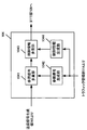
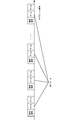
- FIG. 1 shows an example of a system configuration according to this embodiment.
- the system includes a base station apparatus 10 and terminal apparatuses 20-1 to 20-Nm.
- the number of terminal devices terminal, mobile terminal, mobile station, UE: “User” Equipment
- the base station apparatus 10 may perform communication using a so-called licensed band obtained from the country or region where the wireless provider provides the service, or use permission from the country or region. Communication using a so-called unlicensed band that is not required may be performed.
- the base station apparatus 10 may be a macro base station apparatus with a wide coverage, or a small cell base station or a pico base station apparatus (Pico ⁇ ⁇ ⁇ ⁇ ⁇ eNB: NBevolved Node B, SmallCell, Low Also called Power Node, Remote Radio Head).
- the frequency band other than the license band is not limited to the example of the unlicensed band, and may be a white band (white space) or the like.
- the base station apparatus 10 may apply a CA (Carrier Aggregation) technique that uses a plurality of component carriers (CC: Component Carrier or Serving cell) in a band used in LTE communication. Communication different from MTC may be transmitted by different CCs, or may be transmitted by the same CC.
- CA Carrier Aggregation
- communication different from MTC may be PCell (Primary cell) and MTC communication may be SCell (Secondary cell). Further, subcarriers (frequency), slots or subframes (time) to be used may be divided by communication and MTC different from MTC in the same CC.
- the terminal devices 20-1 to 20-Nm can transmit MTC data to the base station device 10.
- the terminal devices 20-1 to 20-Nm receive control information necessary for data transmission in advance from the base station device 10 or another base station device when connected to the base station.
- the terminal devices 20-1 to 20-Nm do not need to receive a scheduling request (SR: ulScheduling Request) transmission or transmission permission control information (UL Grant) transmitted by the base station device after transmission data (traffic) occurs.
- SR ulScheduling Request
- UL Grant transmission permission control information
- Wireless communication technology also called contention-based wireless communication technology, contention-based access, grant free access, grant free communication, grant free data transmission, grantless access, autonomous access, etc. Data transmission).
- the terminal devices 20-1 to 20-Nm are wireless communication technologies (non-contention based wireless communication) that require SR transmission such as LTE (Long Term Evolution), LTE-Advanced, LTE-Advanced Pro, and UL Grant reception.
- SR transmission such as LTE (Long Term Evolution), LTE-Advanced, LTE-Advanced Pro, and UL Grant reception.
- Technology, Grant-based access, Grant-based communication, Grant-based data transmission, Scheduled access, etc. (hereinafter referred to as non-contention based wireless communication technology)
- the contention-based wireless communication technology and the non-contention-based wireless communication technology may be switched and used according to the size, the quality of service (QoS: “Quality of Service”), and the like.
- QoS Quality of Service
- terminal apparatuses 20-1 to 20-Nm transmit data using radio resources scheduled from the base station apparatus by performing SR transmission before performing data transmission, or perform radio transmission designated in advance before data generation. It may be determined whether data is transmitted in at least a part of the resource.
- QoS may include data transmission reliability, delay time for data transmission, and communication speed, and power consumption for data transmission of the terminal device (for example, power per bit in data transmission). There may be indicators such as.
- the terminal devices 20-1 to 20-Nm are not limited to the MTC, and enable H2M communication (Human-to-Machine Communication) or H2H communication (Human-to-Human Communication) involving humans. Also good.
- the base station apparatus 10 uses UL scheduling, which is control information including transmission parameters used for data transmission by dynamic scheduling or SPS (Semi-Persistent Scheduling) depending on the type of data, as PDCCH (Physical Downlink Control CHannel) or EPDCCH. (Enhanced PDCCH) or other physical channel for transmitting downlink control information may be transmitted.
- UL scheduling which is control information including transmission parameters used for data transmission by dynamic scheduling or SPS (Semi-Persistent Scheduling) depending on the type of data, as PDCCH (Physical Downlink Control CHannel) or EPDCCH. (Enhanced PDCCH) or other physical channel for transmitting downlink control information may be transmitted.
- the terminal devices 20-1 to 20-Nm perform data transmission based on UL Grant transmission parameters.
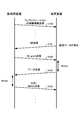
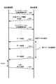
- FIG. 2 shows an example of a sequence chart of data transmission of a terminal device according to the conventional wireless communication technology.
- the base station device transmits configuration control information when the terminal device is connected (S100). Configuration control information may be notified by RRC (Radio Resource Control), upper layer control information such as SIB (System Information Block), or DCI format.
- RRC Radio Resource Control
- SIB System Information Block
- the physical channel to be used may be PDCCH, EPDCCH, PDSCH (Physical Downlink Shared CHannel), or other physical channels.
- the terminal device transmits SR to request UL Grant (S101). After receiving the SR, the base station apparatus transmits UL Grant to the terminal apparatus using PDCCH or EPDCCH (S102).
- the terminal device In the case of FDD (also referred to as Frequency Division Duplex or frame structure type 1), the terminal device is a subframe 4 msec after a subframe in which UL Grant is detected by blind decoding of PDCCH and EPDCCH, and is included in UL Grant. Data transmission based on the parameters is performed (S103).
- TDD also referred to as “Time Division Duplex” or “frame structure type 2”
- it is not limited to 4 msec, but will be described on the assumption of FDD in order to simplify the description.
- the base station apparatus detects data transmitted by the terminal apparatus, and transmits ACK / NACK indicating whether or not there is an error in the data detected in the subframe 4 msec after the subframe in which the data signal is received (S104).
- S101 when the resource for SR transmission is not notified by RRC, the terminal device requests UL Grant using PRACH (Physical Random Access CHannel).
- PRACH Physical Random Access CHannel
- S102 data transmission of only one subframe is possible in the case of dynamic scheduling, but periodic data transmission is permitted in the case of SPS, and information such as the SPS period is notified by the RRC of S100.
- the terminal device stores a transmission parameter such as an SR transmission resource notified by RRC from the base station device, an SPS cycle, and the like.
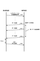
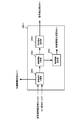
- FIG. 3 shows an example of a sequence chart of data transmission of the terminal device according to the wireless communication technology of the present embodiment.
- the base station apparatus transmits configuration control information when the terminal apparatus is connected (S200).
- the configuration control information may be notified by RRC, upper layer control information such as SIB, or DCI format.
- the physical channel to be used may be PDCCH, EPDCCH, PDSCH, or other physical channels.
- the configuration control information includes radio resources and transmission parameters used in the contention-based radio communication technology.
- the terminal device can also use a non-contention based wireless communication technology such as LTE, LTE-Advanced, LTE-Advanced Pro, etc.
- the control information notified in S100 of FIG. 2 may be included.
- the terminal device When uplink data is generated and the control information of S200 is received, the terminal device transmits data using contention-based wireless communication technology that does not require SR transmission or UL Grant transmission transmitted by the base station device. (S201-1).
- the terminal device is notified of the same data transmission count, transmission period, transmission cycle, radio resources used for transmission, transmission parameters, etc. in S200, and requested QoS (data transmission reliability, data transmission
- the same data as S201-1 is transmitted based on the control information received in S200 (S201-2 to S201-L).
- the base station apparatus detects the data transmitted by the terminal apparatus, and transmits ACK / NACK indicating whether or not there is an error in the data detected in the subframe Xmsec after the subframe receiving the data signal (S202).
- X may be set to 4 from data transmission or may be a different value.
- the last data transmission (S201-L) is used as a reference.
- the base station apparatus may use a subframe in which data can be detected without error as a reference after Xmsec. May stop the same data transmission when the terminal detects ACK / NACK.
- ACK / NACK may not be transmitted, and the base station apparatus may switch the transmission / non-transmission of ACK / NACK depending on the non-contention-based and contention-based wireless communication technology.
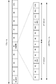
- FIG. 4 shows an example of an uplink frame configuration related to the conventional wireless communication technology.
- one frame is 10 msec, 10 subframes are configured, 1 subframe is configured by 2 slots, and 1 slot is configured by 7 OFDM symbols.
- DMRS De-Modulation Reference Signal
- OFDM symbol # 4 a demodulation reference signal
- FIG. 5 shows an example of an uplink frame configuration according to the wireless communication technique of this embodiment. This figure is an example in which the frame configuration is the same as in FIG.
- the terminal device can transmit data immediately after data is generated, and when data is generated before subframe # 1, data transmission shown in the example of FIG. 5 is performed. In subframe # 1, a transmission terminal identification signal is transmitted, and in subframe # 2, data is transmitted. Details of the transmission terminal identification signal and the data transmission method will be described later.
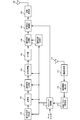
- FIG. 6 shows an example of the configuration of the terminal device according to the present embodiment.
- the terminal device is assumed to be able to use both the contention-based wireless communication technology and the above-described conventional non-contention-based wireless communication technology for MTC data transmission like the terminal devices 20-1 to 20-Nm.
- the present invention can also be applied when the terminal apparatus can use only the contention-based wireless communication technology. In this case, there is no processing related to the non-contention-based wireless communication technology, but the basic configuration is the same.
- the terminal apparatus receives control information transmitted from the base station apparatus via EPDCCH, PDCCH, and PDSCH by the reception antenna 110.
- the radio reception unit 111 down-converts the received signal to a baseband frequency, performs A / D (Analog / Digital: analog / digital) conversion, and removes a CP (Cyclic Prefix) from the digital signal.
- the control information detection unit 112 detects a DCI (Downlink Control Information) format addressed to the own station transmitted by PDCCH or EPDCCH by blind decoding. Blind decoding performs decoding processing on the candidate CSS (Common Search Space) or USS (UE-specific Search Space) in which the DCI format is placed, and cyclic redundancy check (CRC: Cyclic Redundancy added to the data signal) If it can be detected without error bits in (Check), it is detected as control information addressed to its own station.
- DCI Downlink Control Information
- the base station device can perform exclusive OR with C-RNTI (Cell-Radio Network Temporary Identifier) or SPS C-RNTI, which is an ID unique to the destination terminal device.
- C-RNTI Cell-Radio Network Temporary Identifier
- SPS C-RNTI SPS C-RNTI
- the terminal device performs an exclusive OR operation on the CRC and C-RNTI or SPS C-RNTI, and determines whether or not there is an error bit in the CRC of the operation result.
- DCI format a plurality of formats are defined according to the use, and DCI format 0 for uplink single antenna, DCI format 4 for MIMO (Multiple-Input-Multiple-Output), and the like are defined.
- the control information detection unit 112 also performs detection when an RRC signal is received.
- the control information detection unit 112 inputs the detected control information to the transmission parameter storage unit 113.
- the transmission parameter storage unit 113 inputs control information to the traffic management unit 114 when receiving UL Grant such as dynamic scheduling or SPS.
- the transmission parameter storage unit 113 retains the control information until data transmission is performed using the contention-based wireless communication technology.
- the configuration control information held by the transmission parameter storage unit 113 will be described later.
- the traffic management unit 114 receives a bit string of transmission data, receives control information when receiving UL Grant, and controls the configuration information for contention-based wireless communication technology in advance. Information is also entered. Further, the traffic management unit 114 may also input the type of transmission data, QoS, and the like. The traffic management unit 114 selects the use of contention-based or non-contention-based radio communication technology from the input information, and transmits the transmission parameters of the selected radio communication technology as an error correction coding unit 101, modulation unit 102, transmission The data is input to the signal generator 103, the signal multiplexer 104, and the identification signal generator 115, and the data bit string is input to the error correction encoder 101.
- the error correction encoding unit 101 encodes an error correction code on the input data bit string.
- the error correction code for example, a turbo code, an LDPC (Low Density Parity Check) code, a convolutional code, a Polar code, or the like is used.
- the type and coding rate of the error correction code performed by the error correction coding unit 101 may be determined in advance by the transmission / reception apparatus, may be input from the traffic management unit 114, or may be contention-based or non-coding. Switching may be performed by contention-based wireless communication technology. When the error correction coding type and coding rate are notified as control information, these pieces of information are input from the traffic management unit 114 to the error correction coding unit 101.
- the error correction encoding unit 101 may perform puncturing (decimation) and interleaving (rearrangement) of the encoded bit string in accordance with the applied coding rate.
- the error correction encoding unit 101 performs interleaving differently for each terminal device when interleaving the encoded bit string.
- the error correction coding unit 101 may apply scrambling.
- scramble may be applied only when the base station apparatus can uniquely determine the scramble pattern used by the terminal apparatus by an identification signal described later.
- a spread code may be used for coded bits obtained by error correction coding. Spread codes may be used at all coding rates used in data transmission, or spread codes may be used only at specific coding rates.
- An example of using a spreading code only for a specific coding rate is only when data is transmitted at a coding rate lower than the coding rate for transmitting all of the coded bits obtained by error correction coding (even if it is a turbo code). For example, only below 1/3), a spreading code is used. Even if switching is performed such as using a spread code when transmitting data with a low coding rate using contention-based wireless communication technology and not using a spread code when transmitting data with a low coding rate using non-contention-based wireless communication technology. good.
- the modulation unit 102 receives the modulation scheme information from the traffic management unit 114 and modulates the encoded bit sequence input from the error correction encoding unit 101 to generate a modulation symbol sequence.
- the modulation method include QPSK (Quaternary Phase Shift Keying), 16 QAM (16-ary Quadrature Amplitude Modulation) 64 QAM, and 256 QAM.
- the modulation method may not be Gray labeling, and set partitioning may be used. Further, GMSK (Gaussian Minimum-Shift ⁇ Keying) may be used.
- Modulation section 102 outputs the generated modulation symbol sequence to transmission signal generation section 103.
- the modulation method or modulation method may be determined in advance by the transmission / reception device, may be input from the traffic management unit 114, or may be switched by a contention-based or non-contention-based wireless communication technology. good.
- a spreading code may be used. This means that the spread code is not applied to the encoded bit string after the error correction encoding but applied to the modulation symbol string. All modulation multi-level numbers (number of bits included in one modulation symbol) used for data transmission or spreading codes may be used at the coding rate, or all MCS (Modulation and Coding Scheme) (Spread code) may be used, or a spread code may be used with a specific modulation multilevel number, a specific coding rate, or a specific MCS.
- MCS Modulation and Coding Scheme
- An example of using a spreading code with a specific modulation multi-level number uses a spreading code only during BPSK or QPSK data transmission.
- An example of using a spreading code at a specific coding rate is only when data is transmitted at a coding rate lower than the coding rate for transmitting all of the coded bits obtained by error correction coding (even if it is a turbo code). (Only if less than 1/3) spread code is used.
- An example of using a spreading code in a specific MCS is only when data is transmitted at a coding rate lower than the coding rate in the case of transmitting all of the coded bits obtained by BPSK, QPSK and error correction coding (turbo code). (Only if less than 1/3) spread code is used.
- switching may be performed such that a spread code is used at the time of data transmission at a low coding rate by the contention-based wireless communication technology and a spread code is not used at the time of data transmission by the non-contention-based wireless communication technology.
- the DFT unit 1031 performs discrete Fourier transform on the input modulation symbol, thereby converting the time domain signal into the frequency domain signal, and outputs the obtained frequency domain signal to the signal allocation unit 1032.
- the signal allocation unit 1032 receives resource allocation information, which is information of one or more RBs (Resource Block) used for data transmission, from the traffic management unit 114, and allocates a frequency domain transmission signal to the designated RB.
- the resource allocation information input from the traffic management unit 114 is notified by UL Grant in the case of non-contention based wireless communication technology, and is notified in advance by configuration control information in the case of contention based wireless communication technology. .
- 1 RB is defined by 12 subcarriers and 1 slot (7 OFDM symbol), and the resource allocation information is information for allocating 1 subframe (2 slots).
- 1 subframe is 1 msec and the subcarrier interval is 15 kHz, but the time and subcarrier interval of 1 subframe is 4 msec, 3.75 kHz, 2 msec, 7.5 kHz, 0.2 msec, 75 kHz or , 0.1 msec, 150 kHz, etc.
- resource allocation information may be notified in units of one subframe even in different frame configurations.
- the resource allocation information may notify the allocation of a plurality of subframes regardless of whether it is the same as the LTE subframe configuration or different from the LTE subframe configuration.
- Notification may be sent, allocation in units of OFDM symbols may be notified, or allocation in units of a plurality of OFDM symbols such as 2 OFDM symbols may be notified.
- the resource allocation information may be in units of one subcarrier, not in units of RBs, in units of RBGs (Resource Block Group) composed of a plurality of RBs, and may be allocated to one or more RBGs.
- the resource allocation information is not limited to continuous RBs or continuous subcarriers, but may be discontinuous RBs or discontinuous subcarriers.
- the terminal apparatus may use only a part of the RB or subcarrier indicated by the resource allocation information for data transmission. In this case, the base station apparatus needs to notify the information of the RB and subcarrier used by the terminal apparatus for data transmission in advance or be able to detect from other signals.
- phase rotation section 1030 performs phase rotation on the input modulation symbol.
- the phase rotation applied to the time domain data signal in the phase rotation unit 1030 uses a pattern input from the traffic management unit 114 in order to apply a different pattern for each terminal device.
- An example of the phase rotation pattern is a pattern in which the phase rotation is different for each modulation symbol. It is assumed that the phase rotation pattern input by the traffic management unit 114 is shared between the terminal device and the base station device by being notified by UL Grant or by being notified in advance by configuration control information.
- the DFT unit 1031 and the signal allocation unit 1032 are the same as those in FIG. Here, FIG.
- a different cyclic delay may be given to the frequency domain signal obtained by the DFT unit 1031 for each terminal device.
- the frequency domain signal of the terminal device 20-u that is not cyclically delayed is S U (1), S U (2), S U (3), S U (4)
- the terminal device 20- A cyclic delay having a delay amount of 1 symbol is given to i
- S i (4), S i (1), S i (2), S i (3) are set.
- the DFT unit 1031 and the signal allocation unit 1032 in FIG. 9 are the same as those in FIG.
- the phase rotation unit 1033 performs phase rotation on the frequency domain data signal obtained by the DFT unit 1031.
- the phase rotation applied to the frequency domain data signal in the phase rotation unit 1033 uses a pattern input from the traffic management unit 114 in order to apply a different pattern for each terminal device.
- An example of the phase rotation pattern is a different phase rotation for each data signal unit (subcarrier unit) in the frequency domain.
- the phase rotation pattern input by the traffic management unit 114 is assumed to be information shared between the terminal apparatus and the base station apparatus, for example, notified by UL Grant or previously notified by configuration control information.
- the DFT unit 1031 may give different cyclic delays to the modulation symbols before conversion into frequency domain signals for each terminal apparatus. Specifically, when the time domain signal of the terminal device 20-u that does not have a cyclic delay is s U (1), s U (2), s U (3), and s U (4), the terminal device 20- A cyclic delay having a delay amount of 1 is given to i to make s i (4), s i (1), s i (2), s i (3), and so on. Further, both the phase rotation unit 1030 and the phase rotation unit 1033 of FIGS. 8 and 9 may be used.
- the transmission signal generation unit 103 in FIGS. 7 to 9 inputs the transmission signal to the signal multiplexing unit 104.
- the configuration of the transmission signal generation unit 103 may be the configuration of FIG.
- the transmission signal generation unit 103 performs interleaving (rearrangement) on the modulation symbols input before the DFT unit 1031.
- interleaving is performed on the modulation symbols
- different interleaving is performed for each terminal apparatus. It is not limited to the example of using interleaving different for each terminal device shown in FIG. 10, but using interleaving different for each terminal device with respect to the encoded bit string obtained from the error correction coding unit 101. Also good.
- interleaving that is different for each terminal apparatus after applying the spreading code may be used, or different for each terminal apparatus before the spreading code is applied. Interleaving may be used.
- FIG. 11 shows an example of the configuration of the signal multiplexing unit 104 according to the present embodiment.
- the transmission signal input from the transmission signal generation unit 103 is input to the reference signal multiplexing unit 1041.
- the traffic management unit 114 inputs a parameter for generating a reference signal to the reference signal generation unit 1042, and inputs control information to be transmitted to the base station apparatus to the control information generation unit 1044.
- the reference signal multiplexing unit 1041 multiplexes the input transmission signal and the reference signal sequence (DMRS) generated by the reference signal generation unit.
- DMRS reference signal sequence
- the frame structure shown in FIG. 4 is generated by multiplexing the transmission signal and DMRS.
- the frame configuration in FIG. 5 will be described later.
- the reference signal multiplexing section 1041 may multiplex the data signal and the reference signal in the time domain when arranged in an OFDM symbol different from the data signal as in the frame configuration of FIG.
- control information generation unit 1044 transmits channel quality information (CSI: Channel State Information), SR (Scheduling Request), and ACK / NACK (Acknowledgement / Negative) of uplink control information transmitted by PUCCH (Physical Uplink Control CHannel). Acknowledgment) is generated and output to the control information multiplexing unit 1043.
- the control information multiplexing unit 1043 multiplexes control information for a frame configuration composed of a data signal and a reference signal.
- the signal multiplexing unit 104 inputs the generated transmission frame to the IFFT unit 105.
- the terminal device cannot perform simultaneous transmission of PUSCH and PUCCH (when there is no Capability for simultaneous transmission), only a signal with a high priority is transmitted according to a predetermined signal priority.
- the terminal device can simultaneously transmit PUSCH and PUCCH (when there is Capability of simultaneous transmission) (when there is Capability of simultaneous transmission)
- Only signals with high priority are transmitted according to the priority order of the signals.
- the signal transmission priority may be different between the contention-based wireless communication technology and the non-contention-based wireless communication technology.
- priority exists in the data to transmit, and the priority of PUSCH may change with the priority.
- the IFFT unit 105 receives a frequency-domain transmission frame and performs inverse fast Fourier transform on each OFDM symbol unit to convert the frequency-domain signal sequence into a time-domain signal sequence.
- IFFT unit 105 inputs the time domain signal sequence to identification signal multiplexing unit 106.
- the identification signal generation unit 115 generates a signal to be transmitted in the identification signal subframe of FIG. 5 and inputs the signal to the identification signal multiplexing unit 106. Details of the identification signal will be described later.
- Identification signal multiplexing section 106 multiplexes the time domain signal sequence and the identification signal into different subframes as shown in FIG. 5 and inputs the multiplexed signal to transmission power control section 107.
- the transmission power control unit 107 performs transmission power control using only the open loop transmission power control value or both the open loop and closed loop transmission power control values, and transmits the signal sequence after the transmission power control to the transmission processing unit 108.
- the transmission processing unit 108 inserts a CP into the input signal sequence, converts it into an analog signal by D / A (Digital / Analog) conversion, and converts the converted signal to a radio frequency used for transmission. Up-convert.
- the transmission processing unit 108 amplifies the up-converted signal with PA (Power-Amplifier), and transmits the amplified signal via the transmission antenna 109.
- PA Power-Amplifier
- the terminal device performs data transmission.
- a DFTS-OFDM also called Discrete Fourier Transform Spread Orthogonal Frequency Division Multiplexing, SC-FDMA
- SC-FDMA Discrete Fourier Transform Spread Orthogonal Frequency Division Multiplexing
- the terminal apparatus does not perform DFT in the transmission signal generation unit 103, that is, in a configuration in which the DFT unit 1031 does not exist in any of FIGS. 7 to 10, it means that the OFDM signal is transmitted.
- the terminal device may use the above-described method in the transmission signal generation unit 103, or may use a different spreading method or a different transmission signal waveform generation method.
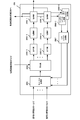
- FIG. 12 shows an example of the configuration of the base station apparatus according to this embodiment.
- the base station apparatus receives data transmitted from the terminal apparatus through N reception antennas 201-1 to 201-N and inputs the data to the reception processing sections 202-1 to 202-N, respectively.
- Reception processing sections 202-1 to 202-N downconvert the received signal to a baseband frequency, perform A / D conversion, and remove the CP from the digital signal.
- Reception processing sections 202-1 to 202-N output signals after CP removal to identification signal separation sections 203-1 to 203-N.
- Identification signal separation sections 203-1 to 203-N separate the identification signal and other signals and output them to transmitting terminal identification section 211 and FFT sections 204-1 to 204-N, respectively.
- Transmitting terminal identifying section 211 identifies a terminal apparatus that has transmitted data from an identification signal described later, and outputs information on the transmitting terminal apparatus to propagation path estimating section 207 and signal demultiplexing sections 205-1 to 205-N.
- the FFT units 204-1 to 204-N convert the input received signal sequence from a time domain signal sequence to a frequency domain signal sequence by fast Fourier transform, and the frequency domain signal sequence is converted to signal separation units 205-1 to 205-N. Output to.
- the signal separators 205-1 to 205-N all have a common configuration, and FIG. 13 shows an example of the configuration of the signal separator 205-1 according to the present embodiment.
- the frequency domain signal sequence is input from the FFT unit 204-1 to the reference signal demultiplexing unit 2051, and the information of the transmitting terminal device identified by the transmitting terminal identifying unit 211 is input.
- the reference signal demultiplexing unit 2051 demultiplexes the frequency domain signal sequence into a reference signal and other signals using the input information of the transmitting terminal apparatus, and outputs them to the channel estimation unit 207 and the control information demultiplexing unit 2052, respectively.
- the control information separation unit 2052 separates the input signal into a control signal and a data signal, and outputs them to the control information detection unit 2054 and the allocation signal extraction unit 2053, respectively.
- the control information detection unit 2054 detects a signal transmitted on the PUCCH. Since the SR is used for uplink scheduling, the CSI is used for downlink scheduling, and the ACK / NACK is used for retransmission control of downlink transmission, the control information generation unit 208 is used. Output to.
- the allocation signal extraction unit 2053 extracts a transmission signal for each terminal device based on the resource allocation information notified to the terminal device by the control information.
- the propagation path estimation unit 207 receives information of a transmission terminal apparatus identified as DMRS (De-Modulation Reference Signal) which is a reference signal multiplexed and transmitted with a data signal, estimates a frequency response, and performs demodulation. The estimated frequency response is output to the signal detection unit 206. Moreover, the propagation path estimation part 207 estimates the frequency response used by the next scheduling, when SRS (Sounding * Reference * Signal) is input.
- the control information generation unit 208 performs uplink scheduling and adaptive modulation and coding (also called adaptive modulation and coding, also called link adaptation) based on the frequency response estimated by DMRS or SRS, and the terminal device performs uplink transmission. A transmission parameter to be used is generated and converted into a DCI format.
- Control information generation section 208 generates control information for reporting ACK / NACK in uplink transmission when information on whether there is an error in the received data signal is input from signal detection section 206.
- ACK / NACK in uplink transmission is transmitted by PHICH (PhysicalICHARQ CHannel) or at least one of PDCCH and EPDCCH.
- the control information transmission unit 209 receives the control information converted from the control information generation unit 208, assigns the input control information to the PDCCH and the EPDCCH, and transmits the control information to each terminal device.
- FIG. 14 shows an example of the configuration of the signal detection unit 206 according to the present embodiment.
- the signal for each terminal device extracted from the signal separation units 205-1 to 205-N is input to the cancellation processing unit 2061.
- the cancel processing unit 2061 receives the soft replica from the soft replica generation unit 2067 and performs a cancel process on each received signal.
- the equalization unit 2062 generates an equalization weight based on the MMSE standard from the frequency response input from the propagation path estimation unit 207, and multiplies the signal after the soft cancellation.
- the equalization unit 2062 outputs the signal for each terminal device after equalization to the IDFT units 2063-1 to 2063-U.
- IDFT sections 2063-1 to 2063-U convert the received signal after frequency domain equalization into a time domain signal. If the terminal device performs cyclic delay, phase rotation, or interleaving on the signal before or after DFT in the transmission process, the cyclic delay, phase rotation, or interleaving is applied to the received signal or time domain signal after frequency domain equalization. Processing to restore is performed.
- the demodulation units 2064-1 to 2064-U receive information of a modulation scheme that has been notified in advance or is determined in advance, and performs demodulation processing on the received signal sequence in the time domain, A bit sequence LLR (Log Likelihood Ratio), that is, an LLR sequence is obtained.
- LLR Log Likelihood Ratio
- decoding units 2065-1 to 2065-U receive information of a coding rate that is notified in advance or is determined in advance, and performs decoding processing on the LLR sequence.
- decoding sections 2065-1 to 2065-U are decoders
- the output external LLR or posterior LLR is output to the symbol replica generation units 2066-1 to 2066-U.
- the difference between the external LLR and the posterior LLR is whether or not the prior LLR input to the decoding units 2065-1 to 2065-U is subtracted from the decoded LLR.
- the signal detection unit 206 inputs the decoding unit 2065-1 to 2065-U. Depuncturing (inserting 0 into the LLR of the thinned bits), deinterleaving (reverting the rearrangement), and descrambling are performed on the LLR sequence.
- the symbol replica generation units 2066-1 to 2066-U generate symbol replicas according to the modulation scheme used by the terminal apparatus for data transmission from the input LLR sequence, and output the symbol replicas to the soft replica generation unit 2067.
- the soft replica generation unit 2067 converts the input symbol replica into a frequency domain signal by DFT, and generates a soft replica by multiplying the frequency response.
- the decoding units 2065-1 to 2065-U make a hard decision on the decoded LLR sequence and perform a cyclic redundancy check (CRC: Cyclic Redundancy) From Check), the presence / absence of error bits is determined, and information on the presence / absence of error bits is output to the control information generation unit 208.
- CRC Cyclic Redundancy
- Symbol replica generation sections 2066-1 to 2066-U generate symbol replicas according to the spreading code and modulation scheme used by the terminal apparatus.
- FIG. 15 shows an example of the configuration of the identification signal of the transmission terminal apparatus according to this embodiment.
- the number of OFDM symbols that can be used for transmitting the identification signal is N OFDM
- the number of subcarriers that can be used for transmitting the identification signal is N SC .
- an OCC sequence having a length T OCC is used.
- the OCC sequence length is a value of 1 ⁇ T OCC ⁇ T OFDM , and it is only necessary that information on the OCC sequence length used between the transmitting and receiving apparatuses can be shared in advance.
- the number of subcarriers each transmission terminal device uses the transmission of the identification signal and T SC.
- T SC Cyclic Shift
- CS pattern number T CS when using the IFDMA (Interleaved Frequency Division Multiple Access) uses a multiple number of patterns T RF. Therefore, the number of orthogonal resources for the identification signal is (N OFDM / T OFDM ) ⁇ T OCC ⁇ (N SC / T SC ) ⁇ T CS ⁇ T RF .
- the configuration control information transmitted by the base station apparatus includes information indicating the orthogonal resource for transmitting the identification signal.
- the 2OFDM symbol to transmit an identification signal defines the OFDM symbol set as T1 ⁇ T7 every 2OFDM successive symbols as in FIG.
- an index I T of the OFDM symbol sets to be actually used there in N SC> T SC
- the information of the subcarrier set is X number of field use is defined as F1 ⁇ FX
- an index I F of the sub-carrier set to be actually used the index of the OCC sequences used as I OCC, the CS pattern used I and CS, multiple patterns of IFDMA used to I RF.
- the control information of the configuration of the base station apparatus transmits (I T, I F, I OCC, I CS, I RF) contains information uniquely indicating the.
- the configuration control information may be information including only a part of (I T , I F , I OCC , I CS , I RF ).
- the OFDM symbol set does not need to be a continuous OFDM symbol, and may be a combination such as OFDM symbol # 1 and OFDM symbol # 8. Also, may not be a sub-carrier also continuous in the sub-carrier set, for example, may be used in a non-continuous on the frequency axis a cluster of a plurality of identification signals is an integral multiple of T RF as a cluster identification signal. Further, the subcarriers S # 1 to S # N SC that can be used for transmitting the identification signal may be the same as or different from the subcarriers that transmit data. When the subcarrier that can be used for transmitting the identification signal is different from the subcarrier that transmits data, the identification signal and the subcarrier that transmits the data signal may partially overlap.
- the number of terminal devices accommodated in the base station device exceeds the number of orthogonal resources of the identification signal, it is necessary to assign the same orthogonal resource to different terminal devices in duplicate.
- the orthogonal resource of the identification signal it is necessary to identify the transmission terminal device by an identifier unique to the terminal device. Specifically, an exclusive OR operation is performed on the CRC added to the data signal using a C-RNTI (Cell-Radio Network Temporary Identifier) which is an ID unique to the terminal device, SPS C-RNTI, or the like.
- C-RNTI Cell-Radio Network Temporary Identifier
- the receiving base station apparatus performs an exclusive OR operation of a plurality of identifiers and CRC after signal detection by SIC, PIC, or turbo equalization, and confirms an identifier in which no error is detected by CRC.
- the transmission terminal device can be identified.
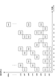
- FIG. 16 shows an example of frequency resources used for uplink data transmission according to the present embodiment.
- the figure shows an example in which different frequency resources are used for each terminal device with respect to frequency resources that can be used for data transmission of contention-based radio access technology.
- the frequency index on the horizontal axis is a subcarrier number
- S (u, i) indicates the i-th frequency domain signal of UE # u.
- UE # 1 uses all available subcarriers and transmits data using a DFTS-OFDM signal
- UEs # 2 to # 8 transmit DFTS-OFDM signals in a discontinuous and equally spaced subcarrier.
- This is an example of transmitting data using.
- PAPR Peak-to-Average-Power-Ratio
- the frequency resource which can be used for data transmission of contention-based radio access technology has been described as 12 subcarriers, the present invention is not limited to this example, and a plurality of 12 subcarriers can be used as one access region.
- the access area may be prepared. For example, by accommodating different terminal devices in each access region, it is possible to accommodate the number of terminal devices that is X times Nm by preparing X access regions.
- the frequency index on the horizontal axis in FIG. 16 is not limited to the subcarrier number, and may be an RB number or an RBG number.
- FIG. 17 shows an example of frequency resources used for uplink data transmission according to the present embodiment.
- the figure shows that DFTS-OFDM signals are continuous subcarriers or discontinuous for some frequency resources for subcarrier indexes # 1 to # 12 that can be used for content-based radio access technology data transmission.
- data is allocated to subcarriers that are equally spaced and transmitted.
- the subcarrier index is divided into # 1 to # 6 and # 7 to # 12.
- different division methods may be used.
- the subcarrier to be used may be divided into three or more and used together with frequency division multiplexing.
- the frequency resource which can be used for data transmission of contention-based radio access technology has been described as 12 subcarriers, the present invention is not limited to this example, and a plurality of 12 subcarriers can be used as one access region.
- the access area may be prepared. For example, by accommodating different terminal devices in each access region, it is possible to accommodate the number of terminal devices that is X times Nm by preparing X access regions.
- the frequency index on the horizontal axis in FIG. 17 is not limited to the subcarrier number, and may be an RB number or an RBG number.
- FIG. 18 shows an example of frequency resources used for uplink data transmission according to the present embodiment.
- This figure shows that DFTS-OFDM signals are transmitted to continuous subcarriers or subcarriers that are not discontinuous at regular intervals for subcarrier indexes # 1 to # 12 that can be used for content-based radio access technology data transmission. It is an example which allocates and transmits.
- a variety of subcarrier usage methods are possible. Therefore, when different frequency resources are used for each terminal device, more frequency resource allocation patterns can be prepared, and the number of terminal devices that can be accommodated can be greatly increased.
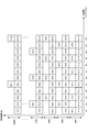
- FIG. 19 shows an example of frequency resources used for uplink data transmission and identification signal transmission according to this embodiment.
- This figure shows the identification signal of the i-th frequency domain of UE #u, with subcarrier indexes # 1 to # 12 that can be used for data transmission of contention-based radio access technology.
- DFTS-OFDM signals are allocated to subcarriers # 1 to # 12 and transmitted by assigning data to continuous subcarriers or subcarriers that are discontinuous and equally spaced. In this case, even if a plurality of terminal apparatuses transmit data in the same subframe, collision occurs only with some frequency resources, and DMRS orthogonalization becomes a problem.
- orthogonalization is realized by CS on the premise that a plurality of data signals collide (multiplex) with the same frequency resource in single user MIMO, multiuser MIMO, or the like.
- orthogonalization by CS cannot be performed, and orthogonalization is performed only by OCC having a sequence length of 2, and the number of terminal devices that can be accommodated is 2. It will be limited to. Therefore, the example of FIG. 19 shares the identification signal and DMRS. That is, in order to realize propagation path estimation using the identification signal, data is arranged without performing DMRS transmission in OFDM symbols # 4 and # 11 in the data transmission subframe (UL transmission subframe) in the frame configuration of FIG. .
- the reference signal multiplexing unit 1041 and the reference signal generation unit 1042 generate DMRS and multiplex the data signal.
- the reference signal multiplexing unit 1041 is shared with the identification signal and DMRS.
- the reference signal generation unit 1042 does nothing.
- the reference signal multiplexing unit 1041 and the reference signal generating unit 1042 generate DMRS and data signals when transmitting data using the non-contention based wireless communication technology. Perform multiplexing.
- the reference signal separation unit 2051 separates the DMRS, but the contention-based wireless communication technique does nothing because the identification signal and the DMRS are shared. However, when the terminal device also uses a non-contention based wireless communication technology, the reference signal separation unit 2051 separates the DMRS at the time of data transmission using the non-contention based wireless communication technology.
- the identification signal uses a subcarrier different from the subcarrier to which the data signal is allocated. Specifically, the identification signal uses all of the subcarriers # 1 to # 12 that can be used for data transmission of contention-based radio access technology, and the data signal is a part of UE # 2 to Nm in FIG. Only subcarriers are used. As shown in FIG. 19, when the subcarriers used for transmitting the identification signal match between UEs # 1 to Nm, orthogonalization in CS is possible, and the number of terminal devices that can be accommodated can be increased.
- the frequency resource which can be used for data transmission of contention-based radio access technology has been described as 12 subcarriers, the present invention is not limited to this example, and a plurality of 12 subcarriers can be used as one access region.
- the access area may be prepared. For example, by accommodating different terminal devices in each access region, it is possible to accommodate the number of terminal devices that is X times Nm by preparing X access regions.
- the frequency index on the horizontal axis in FIG. 19 is not limited to the subcarrier number, but may be an RB number or an RBG number.
- the example of FIG. 19 shows an example in which the number of subcarriers used for transmitting the identification signal is larger than the number of subcarriers used for data transmission.
- the number of subcarriers used for the identification signal may be less than the number of subcarriers used.
- the subcarrier is divided into # 1 to # 6 and # 7 to 12, and the terminal apparatus uses only # 1 to 6 or # 7 to 12 as the subcarrier used for transmitting the identification signal.
- the number of subcarriers used for an identification signal becomes smaller than the number of subcarriers used for data transmission.
- the subcarrier used by the terminal device for transmitting the identification signal may be determined by assigning a subcarrier for transmitting data. For example, when data transmission is performed using subcarriers such as UE # 5 in FIG. 18, since the number of subcarriers for data transmission is larger in subcarriers # 7 to 12 than in subcarriers # 1 to 6, identification is performed. The signal may be transmitted on subcarriers # 7 to # 12.
- the contention-based wireless communication technology even if multiple terminal devices transmit data in the same subframe by using different frequency resources for each terminal device, some frequencies are used. Collisions are made only with resources, and the amount of interference is reduced.
- PAPR characteristics are improved as compared with signal allocation at non-equal intervals. As a result, it is possible to improve the reception quality and the frequency utilization efficiency of the entire system, and to accommodate a large number of terminals efficiently.
- the configuration example of the terminal device is the same as that of the first embodiment, and is FIG. 6, 7, 8, 9, 10, 11.
- the configuration example of the base station device is also the same as that of the first embodiment. 12, 13, and 14.
- the sequence chart of data transmission of the terminal device is also the same as that in the first embodiment and is shown in FIG. Therefore, in the present embodiment, only different processing will be described, and description of similar processing will be omitted.
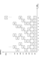
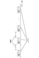
- FIG. 20 shows an example of uplink identification signals and data transmission according to this embodiment. This embodiment is an example in which the same data is transmitted a plurality of times, and shows a case where an identification signal and data are transmitted at each transmission opportunity.
- the terminal device transmits data using the contention-based wireless access technology, the data transmission unit in one subframe shown in FIG.
- Transmission sections T1 to T7 are cases where data is transmitted using only 2 OFDM symbols within one subframe
- transmission sections T8 to 11 are cases where data is transmitted using only 3 OFDM symbols within one subframe
- transmission sections T12 to 15 are This is a case where data is transmitted only with 4 OFDM symbols within one subframe
- transmission intervals T16 to 17 are cases where data is transmitted with only 5 OFDM symbols within one subframe
- transmission intervals T18 to 19 are 6 OFDM within one subframe.
- transmission sections T20 to T21 are cases where data is transmitted with only 7 OFDM symbols (1 slot) in one subframe.
- the terminal apparatus may change the transmission interval for each data transmission in the number of OFDM symbols used for data transmission.
- the subframe number for data transmission is 1 ⁇ Nf ⁇ 10
- the number of selectable transmission sections is Nd
- the transmission section offset given for each terminal device is 0 ⁇ Noff ⁇ Nd ⁇ 1
- the amount of hopping in the transmission section Where 0 ⁇ Nh ⁇ Nd ⁇ 1, it can be calculated by mod (Nf ⁇ Nh + Noff, Nd) +1.
- the probability of collision at the same frequency and the same time may be reduced by changing the frequency resource used for each data transmission. That is, the frequency resource to be used in association with the subframe number for transmitting data of the same data may be changed. For example, the allocation of the frequency resource to be used may be changed according to the subframe number at the time of data transmission as shown in FIG. If the data size to be transmitted is very small, it may be applied to data transmission simultaneously with some OFDM symbols in one subframe (the number of OFDM symbols to be used is 13 or less). When using frequency resources, data is transmitted in slot units or OFDM symbol units in a subframe. In addition, frequency resources and time resources (slot numbers and OFDM symbols) may be changed according to subframe numbers and slot numbers during retransmission.
- the identification signal in FIG. 20 and the number of subframes for transmitting data need not be the same, and the subframe for transmitting data for one subframe for transmitting the identification signal as in the example of FIG. Two may be used.
- the overhead may be reduced by increasing the number of subframes in which data transmission is possible.
- the present invention is not limited to this example.
- the subframe of the present embodiment is used.
- the time / frequency resource for data transmission may be changed depending on the number.
- the invention is not limited to this example.
- the orthogonal resource of the identification signal, the DMRS sequence, and the orthogonal resource The time / frequency resource for data transmission may be changed in association with.
- the present invention can also be applied to cases where the transmission interval in one subframe is different for each terminal device or the number of frequency resources used for data transmission is different for each terminal device.
- predicted traffic information such as the frequency of occurrence of data specific to the terminal device and the predicted data amount is transmitted, and the configuration control information is transmitted based on the predicted traffic information received by the base station device.
- the configuration control information is transmitted based on the predicted traffic information received by the base station device.
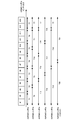
- FIG. 23 shows a sequence chart of data transmission of the terminal device.
- the base station apparatus transmits control information of a configuration that does not change depending on the state and capability of the terminal apparatus and QoS (S300). For example, there are transmission / non-transmission of CSI, transmission / non-transmission of DMRS in the data transmission subframe, transmission / non-transmission of SRS, and the like.
- the terminal device transmits predicted traffic information (S301).
- the predicted traffic information includes the frequency of occurrence of the predicted data (average occurrence cycle), the amount of transmission data (average value of the predicted data amount, maximum value, etc.), required data rate, and reception quality (required Packet error rate).
- the terminal device may transmit Capability and UE category together with the predicted traffic information. Capability includes information on whether HARQ can be used, information on whether a closed loop control value for transmission power control can be used, information on whether fractional transmission power control can be used, information on whether SRS can be transmitted, and the number of transmission / reception antennas Or information on the number of antennas that can be used simultaneously.
- the UE category includes a data rate (data rate that can be transmitted) supported by the terminal device, a buffer size, and the like.
- the terminal device may transmit the predicted traffic information a plurality of times instead of only once at the initial connection or handover.
- the predicted traffic information may be transmitted when a change occurs from the predicted traffic information transmitted by the terminal device.
- information on predicted traffic may be transmitted when a predetermined change amount is determined in advance and the occurrence frequency of predicted data or the amount of transmission data increases or decreases beyond a predetermined change amount.
- the terminal device may periodically transmit the predicted traffic information.
- the base station device After receiving the predicted traffic information from the terminal device, the base station device transmits configuration control information corresponding to the received information (S302). For example, there are frequency resources (frequency position, bandwidth), MCS (Modulation and Coding Scheme), cell-specific and terminal device-specific target reception, and the like.
- the terminal device has a plurality of transmission antennas, the number of transmission layers (number of ranks), MCS for each layer (or for each codeword), and precoding information may also be included.
- steps S201-1 to S202 in FIG. 3 are the same as those in FIG.
- the frequency resource (frequency position, bandwidth) included in the configuration control information transmitted from the base station device based on the predicted traffic information may be determined for each terminal device. That is, the base station apparatus may prepare a plurality of access areas (frequency positions and bandwidths) in which the terminal apparatus is accommodated by contention-based wireless communication technology, or may specify a different access area for each terminal apparatus. As a method for determining an access area to be notified to each terminal apparatus, terminal apparatuses having the same amount of transmission data, a required data rate, and transmission quality may be made the same access area. Further, the base station apparatus may transmit the configuration control information so that the terminal apparatuses accommodated in the same access area use the same MCS for data transmission. In this case, when it is necessary to change the MCS based on the predicted traffic information of the terminal device, the configuration control information may be transmitted again, and the access area may be changed simultaneously with the change of the MCS.
- the terminal device may transmit the transmission power reserve (PH: Power Headroom) simultaneously or periodically with the predicted traffic information.
- the base station apparatus may set the MCS according to the PH.
- the base station apparatus may transmit configuration control information for changing the MCS and the access area when the PH transmitted from the terminal apparatus changes significantly compared to the previous PH.
- DMRS sequences and orthogonal resources may be associated with a coding rate and notified.
- the base station device controls the access region, MCS, and the like based on the predicted traffic information transmitted by the terminal device, so that efficient contention-based Wireless communication can be realized.
- MCS mobility-based channel control
- the base station device controls the access region, MCS, and the like based on the predicted traffic information transmitted by the terminal device, so that efficient contention-based Wireless communication can be realized.
- it is possible to improve the reception quality and the frequency utilization efficiency of the entire system, and to accommodate a large number of terminals efficiently.
- the program that operates on the device related to the present invention may be a program that controls the central processing unit (CPU) and the like to function the computer so as to realize the functions of the embodiments related to the present invention.
- the program or information handled by the program is temporarily stored in a volatile memory such as Random Access Memory (RAM), a non-volatile memory such as a flash memory, a Hard Disk Drive (HDD), or other storage system.
- RAM Random Access Memory
- HDD Hard Disk Drive
- a program for realizing the functions of the embodiments according to the present invention may be recorded on a computer-readable recording medium.
- the “computer system” here is a computer system built in the apparatus, and includes hardware such as an operating system and peripheral devices.
- the “computer-readable recording medium” refers to a semiconductor recording medium, an optical recording medium, a magnetic recording medium, a medium that dynamically holds a program for a short time, or other recording medium that can be read by a computer. Also good.
- each functional block or various features of the apparatus used in the above-described embodiments can be implemented or executed by an electric circuit, for example, an integrated circuit or a plurality of integrated circuits.
- Electrical circuits designed to perform the functions described herein can be general purpose processors, digital signal processors (DSPs), application specific integrated circuits (ASICs), field programmable gate arrays (FPGAs), or other Programmable logic devices, discrete gate or transistor logic, discrete hardware components, or combinations thereof.
- a general purpose processor may be a microprocessor or a conventional processor, controller, microcontroller, or state machine.
- the electric circuit described above may be configured with a digital circuit or an analog circuit. Further, in the case where an integrated circuit technology that replaces the current integrated circuit appears due to the progress of semiconductor technology, the present invention can also use a new integrated circuit based on the technology.
- the present invention is not limited to the above-described embodiment.
- an example of the apparatus has been described.
- the present invention is not limited to this, and a stationary or non-movable electronic device installed indoors or outdoors, such as an AV device, a kitchen device, It can be applied to terminal devices or communication devices such as cleaning / washing equipment, air conditioning equipment, office equipment, vending machines, and other daily life equipment.
- DESCRIPTION OF SYMBOLS 10 Base station apparatus 20-1 to 20-Nm ... Terminal apparatus 101 ... Error correction encoding part 102 ... Modulation part 103 ... Transmission signal generation part 104 ... Signal multiplexing part 105 ... IFFT part 106 ... Identification signal multiplexing part 107 ... Transmission Power control unit 108 ... transmission processing unit 109 ... transmission antenna 110 ... reception antenna 111 ... radio reception unit 112 ... control information detection unit 113 ... transmission parameter storage unit 114 ... traffic management unit 1030 ... phase rotation unit 1031 ... DFT unit 1032 ... signal Allocation unit 1033 ... Phase rotation unit 1034 ... Interleaving unit 1041 ... Reference signal multiplexing unit 1042 ...
- Reference signal generation unit 1043 Control information multiplexing unit 1044 ...
- Control information generation units 201-1 to 201-N Receive antennas 202-1 to 202 -N: reception processing units 203-1 to 203-N ... identification signal separation unit 2
- Reference symbols 04-1 to 204-N FFT units 205-1 to 205-N ...
- Signal separation units 206 ...
- Signal detection units 207 ...
- Propagation path estimation units 208 ...
- Control information generation units 209 ... Control information transmission units 210 ... Transmission antennas 211 ... Transmission terminal identification unit 2051... Reference signal separation unit 2052... Control information separation unit 2053... Assignment signal extraction unit 2054...
Landscapes
- Engineering & Computer Science (AREA)
- Computer Networks & Wireless Communication (AREA)
- Signal Processing (AREA)
- Mobile Radio Communication Systems (AREA)
Abstract
The number of data signals from terminal devices that are non-orthogonally multiplexed in a spatial domain increases when a plurality of terminal devices accommodated by a contention-based wireless communication technology share frequency resources. Consequently, transmission properties deteriorate due to residual interference following the removal of interference during receiving processing, when the number of data signals from the non-orthogonally multiplexed terminals is extremely high. Thus, a transmission device for transmitting a data signal to a receiving device has: a transmission processing unit for transmitting a data signal without receiving control information which allows transmission and is transmitted by the receiving device; a control information receiving unit for receiving in advance a transmission parameter pertaining to the data signal transmission; and a control information transmission unit for transmitting information about the expected traffic. Therein, the control information transmission unit transmits the amount of data and the frequency with which data is generated as the expected traffic information.
Description
本発明は、送信装置、受信装置および通信方法に関する。
The present invention relates to a transmission device, a reception device, and a communication method.
近年、第五世代移動無線通信システム(5G: Fifth Generation mobile telecommunication systems)が注目されており、主に多数の端末装置によるMTC(mMTC: Massive Machine Type Communications)、超高信頼・低遅延通信(Ultra-reliable and low latency communications)、大容量・高速通信(Enhanced mobile broadband)を実現する通信技術の仕様化が見込まれている。特に、今後はIoT(Internet of Things)が多様な機器で実現されることが予想されており、mMTCの実現が5Gの重要な要素の一つになっている。
In recent years, fifth generation mobile radio communication systems (5G: “Fifth Generation” mobile “telecommunication systems”) have attracted attention, mainly MTC (MMTC: “Massive“ Machine ”Type“ Communications ”), ultra-reliable and low-delay communication (Ultra). -reliable (and low-latency-communications) and high-capacity, high-speed communication (enhanced mobile broadband) specifications are expected. In particular, it is expected that IoT (Internet of Things) will be realized in various devices in the future, and realization of mMTC is one of the important elements of 5G.
例えば、3GPP(3rd Generation Partnership Project)では、小さいサイズのデータ送受信を行なう端末装置を収容するMTC(Machine Type Communication)として、M2M(Machine-to-Machine)通信技術の標準化がされている(非特許文献1)。さらに、低レートでのデータ送信を狭帯域でサポートするため、NB-IoT(Narrow Band-IoT)の仕様化も進められている(非特許文献2)。
For example, in 3GPP (3rd Generation Partnership Project), M2M (Machine-to-Machine) communication technology is standardized as MTC (Machine Type Communication) that accommodates terminal devices that transmit and receive small-sized data (non-patented). Reference 1). Furthermore, in order to support data transmission at a low rate in a narrow band, the specification of NB-IoT (Narrow Band-IoT) is also in progress (Non-Patent Document 2).
3GPPで仕様化されているLTE(Long Term Evolution)、LTE-Advanced、LTE-Advanced Proなどでは、端末装置が送信データのトラフィック発生時にスケジューリング要求(SR: Scheduling Request)を送信し、基地局装置より送信許可の制御情報(UL Grant)を受信した後に、所定のタイミングでUL Grantに含まれる制御情報の送信パラメータでデータ送信を行なう。このように基地局装置が全ての上りリンクのデータ送信(端末装置から基地局装置へのデータ送信)の無線リソース制御を行なう無線通信技術を実現している。よって、基地局装置は、無線リソース制御により直交多元接続(OMA: Orthogonal Multiple Access)を実現でき、簡易な受信処理により上りリンクのデータ受信を可能としている。
In LTE (Long Termination Evolution), LTE-Advanced, LTE-Advanced Pro, etc. specified in 3GPP, the terminal device sends a scheduling request (SR: Scheduling Request) when transmission data traffic occurs, from the base station device After receiving the transmission permission control information (UL Grant), data transmission is performed with a transmission parameter of the control information included in the UL Grant at a predetermined timing. In this way, a radio communication technique is implemented in which the base station apparatus performs radio resource control for all uplink data transmission (data transmission from the terminal apparatus to the base station apparatus). Therefore, the base station apparatus can realize orthogonal multiple access (OMA: Orthogonal Multiple Access) by radio resource control, and can receive uplink data by a simple reception process.
一方、このような従来の無線通信技術では、基地局装置が全ての無線リソース制御を行なうために、端末装置が送信するデータ量に関わらず、データ送信前に制御情報の送受信が必要であり、特に送信するデータサイズが小さいと相対的に制御情報の占める割合が高くなる。そこで、端末が小さいサイズのデータ送信を行なう場合、端末装置がSR送信や基地局装置が送信するUL Grantの受信なしにデータ送信を行なうコンテンションベース(Grant Free)の無線通信技術が制御情報によるオーバヘッドの観点で効果的である。さらに、コンテンションベースの無線通信技術では、データ発生からデータ送信までの時間も短くできる。
On the other hand, in such a conventional radio communication technology, since the base station apparatus performs all radio resource control, transmission and reception of control information is required before data transmission regardless of the amount of data transmitted by the terminal apparatus, In particular, when the data size to be transmitted is small, the proportion of control information is relatively high. Therefore, when a terminal transmits data of a small size, a contention-based (Grant Free) wireless communication technique in which the terminal apparatus transmits data without receiving SR transmission or UL Grant transmitted by the base station apparatus is based on control information. This is effective from the viewpoint of overhead. Furthermore, contention-based wireless communication technology can shorten the time from data generation to data transmission.
しかしながら、多数の端末装置がコンテンションベースの無線通信技術で上りリンクのデータ送信を行なう場合、複数の端末装置で周波数リソースを共有することが想定され、複数の端末装置のデータ信号が同一時間・同一周波数で衝突する問題がある。データ信号が同一時間・同一周波数で衝突し、基地局の受信アンテナ数を超える端末装置からデータが空間領域で非直交多重される場合であっても、基地局装置が受信処理に逐次干渉キャンセラ(SIC: Successive Interference Canceller)や並列干渉キャンセラ(PIC: Parallel Interference Canceller)、SLIC(Symbol Level Interference Canceller)、ターボ等化(Iterative SIC、Turbo SIC、Iterative PICとも呼称される)などを適用することで、送信データ信号の検出をすることが可能である。ただし、コンテンションベースの無線通信技術で収容されている多数の端末装置が周波数リソースを共有する場合、収容端末装置数が多くなるほど空間領域で非直交多重される端末装置のデータ信号数が増加する。非直交多重される端末のデータ信号数が非常に多くなると受信処理で干渉除去ができず、残留干渉により伝送特性が劣化する問題があった。
However, when a large number of terminal devices perform uplink data transmission using contention-based wireless communication technology, it is assumed that a plurality of terminal devices share frequency resources. There is a problem of collision at the same frequency. Even when data signals collide with each other at the same time and at the same frequency and data is non-orthogonal-multiplexed in the spatial domain from terminal devices exceeding the number of receiving antennas of the base station, the base station device performs successive interference canceller ( By applying SIC (Successive Interference Canceller), Parallel Interference Canceller (PIC: Parallel Interference Canceller), SLIC (Symbol Level Interference Canceller), turbo equalization (also called Iterative SIC, Turbo SIC, Iterative PIC), etc. It is possible to detect a transmission data signal. However, when a large number of terminal devices accommodated by the contention-based wireless communication technology share frequency resources, the number of data signals of the terminal devices that are non-orthogonally multiplexed in the spatial domain increases as the number of accommodated terminal devices increases. . When the number of non-orthogonal multiplexed terminals has a very large number of data signals, there is a problem that interference cannot be removed by reception processing, and transmission characteristics deteriorate due to residual interference.
本発明は上記の点に鑑みてなされたものであり、多数の端末装置がコンテンションベースの無線通信技術で上りリンクのデータ送信を行なう場合の空間領域で非直交多重される信号の干渉軽減を実現する通信方法を提供することにある。
The present invention has been made in view of the above points, and reduces interference of signals that are non-orthogonally multiplexed in the spatial domain when a large number of terminal apparatuses perform uplink data transmission using contention-based wireless communication technology. It is to provide a communication method to be realized.
(1)本発明は上記の課題を解決するためになされたものであり、本発明の一態様は、受信装置に対してデータ信号を送信する送信装置であって、前記受信装置が送信する送信許可の制御情報の受信をせずに前記データ信号を送信する送信処理部と、前記データ信号の送信に係る送信パラメータを予め受信する制御情報受信部と、予測されるトラフィックの情報を制御情報送信部とを有し、前記制御情報送信部は、前記予測されるトラフィックの情報としてデータの発生頻度とデータ量を送信する。
(1) The present invention has been made to solve the above problems, and one aspect of the present invention is a transmission apparatus that transmits a data signal to a reception apparatus, and the transmission that the reception apparatus transmits. A transmission processing unit for transmitting the data signal without receiving permission control information; a control information receiving unit for receiving in advance transmission parameters relating to the transmission of the data signal; The control information transmission unit transmits data occurrence frequency and data amount as the predicted traffic information.
(2)また、本発明の一態様は、前記制御情報送信部が送信する前記予測されるトラフィックの情報に必要とされるデータレートと受信品質が含まれる。
(2) Also, one aspect of the present invention includes a data rate and reception quality required for the predicted traffic information transmitted by the control information transmission unit.
(3)また、本発明の一態様は、前記制御情報送信部は、予測されるトラフィックの情報が所定の変化量を超える増減した場合に、予測されるトラフィックの情報を送信する。
(3) Further, according to one aspect of the present invention, the control information transmitting unit transmits the predicted traffic information when the predicted traffic information increases or decreases beyond a predetermined change amount.
(4)また、本発明の一態様は、数の送信装置のデータ信号を受信する受信装置であって、送信許可の制御情報の送信をせずに送信される前記データ信号を受信する受信処理部と、予測されるトラフィックの情報などの制御情報を検出する制御情報検出部と、前記受信した制御情報により決定される前記データ送信に用いる送信パラメータを予め送信する制御情報送信部と、を有し、前記制御情報送信部は前記予測されるトラフィックの情報からアクセス領域、MCSの少なくとも1つを決定し、制御情報として送信する。
(4) According to another aspect of the present invention, there is provided a receiving apparatus that receives data signals of a number of transmitting apparatuses, and that receives the data signals transmitted without transmitting transmission permission control information. A control information detection unit that detects control information such as predicted traffic information, and a control information transmission unit that transmits in advance transmission parameters used for the data transmission determined by the received control information. The control information transmission unit determines at least one of an access area and MCS from the predicted traffic information, and transmits it as control information.
(5)また、本発明の一態様は、前記制御情報送信部が送信する前記アクセス領域の情報は送信装置がデータ送信に使用する周波数位置と帯域幅が含まれる。
(5) Further, according to one aspect of the present invention, the information on the access area transmitted by the control information transmitting unit includes a frequency position and a bandwidth used by the transmitting apparatus for data transmission.
(6)また、本発明の一態様は、前記制御情報送信部は同一のMCSを使用する送信装置が前記アクセス領域を共有するように、制御情報を送信する。
(6) Further, according to one aspect of the present invention, the control information transmission unit transmits control information so that transmission devices using the same MCS share the access area.
(7)また、本発明の一態様は、前記制御情報検出部が前記予測されるトラフィックの情報を受信した場合に、前記制御情報送信部が前記MCSと前記アクセス領域を同時に変更する制御情報を送信する。
(7) Further, according to one aspect of the present invention, when the control information detection unit receives the predicted traffic information, the control information transmission unit changes the control information for simultaneously changing the MCS and the access area. Send.
(8)また、本発明の一態様は、受信装置に対してデータ信号を送信する送信装置の通信方法であって、前記受信装置が送信する送信許可の制御情報の受信をせずに前記データ信号を送信する送信処理ステップと、前記データ信号の送信に係る送信パラメータを予め受信する制御情報受信ステップと、予測されるトラフィックの情報を制御情報送信ステップとを有し、前記制御情報送信ステップは、前記予測されるトラフィックの情報としてデータの発生頻度とデータ量を送信する。
(8) According to another aspect of the present invention, there is provided a communication method for a transmission apparatus that transmits a data signal to a reception apparatus, wherein the data is transmitted without receiving transmission permission control information transmitted by the reception apparatus. A transmission processing step of transmitting a signal, a control information reception step of receiving in advance transmission parameters relating to the transmission of the data signal, and a control information transmission step of predicting traffic information, wherein the control information transmission step comprises: The frequency of data generation and the amount of data are transmitted as the predicted traffic information.
(9)また、本発明の一態様は、複数の送信装置のデータ信号を受信する受信装置の通信方法であって、送信許可の制御情報の送信をせずに送信される前記データ信号を受信する受信処理ステップと、予測されるトラフィックの情報などの制御情報を検出する制御情報検出ステップと、前記受信した制御情報により決定される前記データ送信に用いる送信パラメータを予め送信する制御情報送信ステップと、を有し、前記制御情報送信ステップは前記予測されるトラフィックの情報からアクセス領域、MCSの少なくとも1つを決定し、制御情報として送信する。
(9) According to another aspect of the present invention, there is provided a communication method of a receiving apparatus that receives data signals of a plurality of transmitting apparatuses, and the data signal transmitted without transmitting transmission permission control information is received. A receiving processing step, a control information detecting step for detecting control information such as predicted traffic information, and a control information transmitting step for transmitting in advance transmission parameters used for the data transmission determined by the received control information; The control information transmission step determines at least one of an access area and MCS from the predicted traffic information and transmits it as control information.
本発明によれば、多数の端末装置がコンテンションベースの無線通信技術で上りリンクのデータ送信を行なう場合に、空間領域で非直交多重される信号の干渉軽減を実現できる。その結果、基地局装置は多数の端末装置の収容と制御情報量の低減を実現できる。
According to the present invention, when many terminal apparatuses perform uplink data transmission using contention-based wireless communication technology, it is possible to reduce interference of signals that are non-orthogonally multiplexed in the spatial domain. As a result, the base station apparatus can accommodate a large number of terminal apparatuses and reduce the amount of control information.
以下、図面を参照しながら、実施形態について説明する。以下の各実施形態では、M2M通信(Machine-to-Machine Communication、MTC(Machine Type Communication)、IoT(Internet of Things)用の通信、NB-IoT(Narrow Band-IoT)、CIoT(Cellular IoT)とも呼称される)を前提として、送信装置をMTC端末(以下、端末装置とする)とし、受信装置を基地局装置として説明する。ただし、この例に限定されるものではなく、セルラシステムの上りリンク伝送にも適用可能であり、その場合は人間が介在したデータ送信する端末装置が送信装置、基地局装置が受信装置となる。また、セルラシステムのダウンリンク伝送にも適用可能であり、その場合はデータ送信における送受信装置が上りリンク伝送と逆になる。また、D2D(Device-to-Device)通信にも適用可能であり、その場合は送信装置も受信装置も共に端末装置になる。
Hereinafter, embodiments will be described with reference to the drawings. In each of the following embodiments, M2M communication (Machine-to-MachineicCommunication, MTC (Machine Type Communication), communication for IoT (Internet of Things), NB-IoT (Narrow Band-IoT), CIOT (Cellular IoT) The transmission device is assumed to be an MTC terminal (hereinafter referred to as a terminal device) and the reception device is assumed to be a base station device. However, the present invention is not limited to this example, and can also be applied to uplink transmission of a cellular system. In this case, a terminal device that transmits data with human intervention is a transmission device, and a base station device is a reception device. Moreover, it is applicable also to the downlink transmission of a cellular system, In that case, the transmission / reception apparatus in data transmission becomes reverse with uplink transmission. The present invention is also applicable to D2D (Device-to-Device) communication. In this case, both the transmission device and the reception device are terminal devices.
図1は、本実施形態に係るシステムの構成の一例を示す。該システムは、基地局装置10、端末装置20-1~20-Nmから構成される。なお、端末装置(端末、移動端末、移動局、UE: User Equipment)の数は限定されない他、各装置のアンテナ数は1であっても良いし、複数あっても良い。また、基地局装置10は無線事業者がサービスを提供する国や地域から使用許可が得られた、いわゆるライセンスバンド(licensed band)による通信を行なっても良いし、国や地域からの使用許可を必要としない、いわゆるアンライセンスバンド(unlicensed band)による通信を行なっても良い。また、基地局装置10は、カバレッジの広いマクロ基地局装置であっても良いし、マクロ基地局装置よりカバレッジが狭いスモールセル基地局またはピコ基地局装置(Pico eNB: evolved Node B、SmallCell、Low Power Node、Remote Radio Headとも呼称される)でも良い。また、本明細書においてライセンスバンド以外の周波数帯域は、アンライセンスバンドの例に限定されず、ホワイトバンド(ホワイトスペース)等でも良い。また、基地局装置10はLTEの通信で用いられる帯域のコンポーネントキャリア(CC: Component CarrierもしくはServing cellとも呼称される)を複数使用するCA(Carrier Aggregation)技術を適用しても良く、MTCと、MTCと異なる通信を異なるCCでデータ伝送しても良いし、同一のCCでデータ伝送しても良い。CAを適用する例としては、MTCと異なる通信をPCell(Primary cell)とし、MTC通信をSCell(Secondary cell)としても良い。また、同一のCC内でMTCと異なる通信とMTCで、使用するサブキャリア(周波数)やスロットもしくはサブフレーム(時間)を分けても良い。
FIG. 1 shows an example of a system configuration according to this embodiment. The system includes a base station apparatus 10 and terminal apparatuses 20-1 to 20-Nm. In addition, the number of terminal devices (terminal, mobile terminal, mobile station, UE: “User” Equipment) is not limited, and the number of antennas of each device may be one or plural. In addition, the base station apparatus 10 may perform communication using a so-called licensed band obtained from the country or region where the wireless provider provides the service, or use permission from the country or region. Communication using a so-called unlicensed band that is not required may be performed. The base station apparatus 10 may be a macro base station apparatus with a wide coverage, or a small cell base station or a pico base station apparatus (Pico カ バ レ ッ ジ eNB: NBevolved Node B, SmallCell, Low Also called Power Node, Remote Radio Head). In this specification, the frequency band other than the license band is not limited to the example of the unlicensed band, and may be a white band (white space) or the like. Further, the base station apparatus 10 may apply a CA (Carrier Aggregation) technique that uses a plurality of component carriers (CC: Component Carrier or Serving cell) in a band used in LTE communication. Communication different from MTC may be transmitted by different CCs, or may be transmitted by the same CC. As an example of applying CA, communication different from MTC may be PCell (Primary cell) and MTC communication may be SCell (Secondary cell). Further, subcarriers (frequency), slots or subframes (time) to be used may be divided by communication and MTC different from MTC in the same CC.
端末装置20-1~20-Nmは、MTCのデータを基地局装置10へ送信可能とする。端末装置20-1~20-Nmは、基地局との接続時に基地局装置10もしくは他の基地局装置より予めデータ送信に必要な制御情報を受信する。端末装置20-1~20-Nmは、送信するデータ(トラフィック)発生後に、スケジューリング要求(SR: Scheduling Request)送信や基地局装置が送信する送信許可の制御情報(UL Grant)の受信の不要な無線通信技術(コンテンションベースの無線通信技術、Contention based access、Grant free access、Grant free communication、Grant free data transmission、Grant less access、autonomous accessなどとも呼称される。以下、コンテンションベースの無線通信技術と呼ぶ)でデータ送信を行なう。ただし、端末装置20-1~20-Nmは、LTE(Long Term Evolution)、LTE-Advanced、LTE-Advanced ProなどのSR送信やUL Grant受信が必要な無線通信技術(ノンコンテンションベースの無線通信技術、Grant-based access、Grant-based communication、Grant-based data transmission、Scheduled accessなどとも呼称される。以下、ノンコンテンションベースの無線通信技術と呼ぶ)も使用できる場合には、送信データやデータサイズ、送信データのサービス品質(QoS: Quality of Service)などに応じて、コンテンションベースの無線通信技術とノンコンテンションベースの無線通信技術を切り替えて使用しても良い。つまり、端末装置20-1~20-Nmは、データ送信を行なう前にSR送信することで基地局装置からスケジューリングされた無線リソースを用いたデータ送信するか、データ発生前に予め指定された無線リソースの少なくとも一部でデータ送信するかを決めても良い。また、QoSには、データ送信の信頼度、データ送信にかかる遅延時間、通信速度が含まれても良く、さらに端末装置のデータ送信に係る消費電力(例えば、データ送信において1ビット当たりの電力)などの指標があっても良い。ここで、端末装置20-1~20-Nmは、MTCのみに限定されず、人が介在するH2M通信(Human-to-Machine Communication)やH2H通信(Human-to-Human Communication)などを可能としても良い。その場合には、基地局装置10がデータの種類によりダイナミックスケジューリングやSPS(Semi-Persistent Scheduling)によりデータ送信に用いる送信パラメータを含む制御情報であるUL GrantをPDCCH(Physical Downlink Control CHannel)、もしくはEPDCCH(Enhanced PDCCH)、もしくはその他の下りリンクの制御情報を送信する物理チャネルで送信しても良い。端末装置20-1~20-Nmは、UL Grantの送信パラメータに基づくデータ送信を行なう。
The terminal devices 20-1 to 20-Nm can transmit MTC data to the base station device 10. The terminal devices 20-1 to 20-Nm receive control information necessary for data transmission in advance from the base station device 10 or another base station device when connected to the base station. The terminal devices 20-1 to 20-Nm do not need to receive a scheduling request (SR: ulScheduling Request) transmission or transmission permission control information (UL Grant) transmitted by the base station device after transmission data (traffic) occurs. Wireless communication technology (also called contention-based wireless communication technology, contention-based access, grant free access, grant free communication, grant free data transmission, grantless access, autonomous access, etc. Data transmission). However, the terminal devices 20-1 to 20-Nm are wireless communication technologies (non-contention based wireless communication) that require SR transmission such as LTE (Long Term Evolution), LTE-Advanced, LTE-Advanced Pro, and UL Grant reception. Technology, Grant-based access, Grant-based communication, Grant-based data transmission, Scheduled access, etc. (hereinafter referred to as non-contention based wireless communication technology) The contention-based wireless communication technology and the non-contention-based wireless communication technology may be switched and used according to the size, the quality of service (QoS: “Quality of Service”), and the like. That is, terminal apparatuses 20-1 to 20-Nm transmit data using radio resources scheduled from the base station apparatus by performing SR transmission before performing data transmission, or perform radio transmission designated in advance before data generation. It may be determined whether data is transmitted in at least a part of the resource. In addition, QoS may include data transmission reliability, delay time for data transmission, and communication speed, and power consumption for data transmission of the terminal device (for example, power per bit in data transmission). There may be indicators such as. Here, the terminal devices 20-1 to 20-Nm are not limited to the MTC, and enable H2M communication (Human-to-Machine Communication) or H2H communication (Human-to-Human Communication) involving humans. Also good. In this case, the base station apparatus 10 uses UL scheduling, which is control information including transmission parameters used for data transmission by dynamic scheduling or SPS (Semi-Persistent Scheduling) depending on the type of data, as PDCCH (Physical Downlink Control CHannel) or EPDCCH. (Enhanced PDCCH) or other physical channel for transmitting downlink control information may be transmitted. The terminal devices 20-1 to 20-Nm perform data transmission based on UL Grant transmission parameters.
(第1の実施形態)
図2に、従来の無線通信技術に係る端末装置のデータ送信のシーケンスチャートの一例を示す。基地局装置は、端末装置が接続時にコンフィグレーションの制御情報を送信する(S100)。コンフィグレーションの制御情報は、RRC(Radio Resource Control)で通知しても良いし、SIB(System Information Block)などの上位層の制御情報でも良いし、DCIフォーマットでも良い。また、使用する物理チャネルは、PDCCHやEPDCCH、PDSCH(Physical Downlink Shared CHannel)でも良いし、その他の物理チャネルを使用しても良い。端末装置は、上りリンクのデータが発生し、UL Grantを受信していない場合、UL Grantを要求するためにSRを送信する(S101)。基地局装置は、SRを受信後、PDCCHやEPDCCHでUL Grantを端末装置に送信する(S102)。端末装置は、FDD(Frequency Division Duplexもしくはframe structure type1とも呼称される)の場合、PDCCHやEPDCCHをブラインドデコーディングでUL Grantを検出したサブフレームの4msec後のサブフレームで、UL Grantに含まれる送信パラメータに基づくデータ送信を行なう(S103)。ただし、TDD(Time Division Duplexもしくはframe structure type2とも呼称される)の場合は、4msecとは限らないが、説明を簡単にするためFDDを前提に説明する。基地局装置は、端末装置が送信したデータを検出し、データ信号を受信したサブフレームから4msec後のサブフレームで検出したデータに誤りがあったか否かを示すACK/NACKを送信する(S104)。ここで、S101において、端末装置はRRCでSR送信用のリソースが通知されていない場合、PRACH(Physical Random Access CHannel)を用いてUL Grantを要求する。また、S102において、ダイナミックスケジューリングの場合は、1サブフレームのみのデータ送信が可能だが、SPSの場合は周期的なデータ送信が許可され、SPSの周期などの情報はS100のRRCで通知されるものとする。端末装置は、基地局装置よりRRCで通知されたSR送信用のリソースなどの送信パラメータやSPSの周期等などを記憶する。 (First embodiment)
FIG. 2 shows an example of a sequence chart of data transmission of a terminal device according to the conventional wireless communication technology. The base station device transmits configuration control information when the terminal device is connected (S100). Configuration control information may be notified by RRC (Radio Resource Control), upper layer control information such as SIB (System Information Block), or DCI format. The physical channel to be used may be PDCCH, EPDCCH, PDSCH (Physical Downlink Shared CHannel), or other physical channels. When uplink data is generated and UL Grant is not received, the terminal device transmits SR to request UL Grant (S101). After receiving the SR, the base station apparatus transmits UL Grant to the terminal apparatus using PDCCH or EPDCCH (S102). In the case of FDD (also referred to as Frequency Division Duplex or frame structure type 1), the terminal device is asubframe 4 msec after a subframe in which UL Grant is detected by blind decoding of PDCCH and EPDCCH, and is included in UL Grant. Data transmission based on the parameters is performed (S103). However, in the case of TDD (also referred to as “Time Division Duplex” or “frame structure type 2”), it is not limited to 4 msec, but will be described on the assumption of FDD in order to simplify the description. The base station apparatus detects data transmitted by the terminal apparatus, and transmits ACK / NACK indicating whether or not there is an error in the data detected in the subframe 4 msec after the subframe in which the data signal is received (S104). Here, in S101, when the resource for SR transmission is not notified by RRC, the terminal device requests UL Grant using PRACH (Physical Random Access CHannel). In S102, data transmission of only one subframe is possible in the case of dynamic scheduling, but periodic data transmission is permitted in the case of SPS, and information such as the SPS period is notified by the RRC of S100. And The terminal device stores a transmission parameter such as an SR transmission resource notified by RRC from the base station device, an SPS cycle, and the like.
図2に、従来の無線通信技術に係る端末装置のデータ送信のシーケンスチャートの一例を示す。基地局装置は、端末装置が接続時にコンフィグレーションの制御情報を送信する(S100)。コンフィグレーションの制御情報は、RRC(Radio Resource Control)で通知しても良いし、SIB(System Information Block)などの上位層の制御情報でも良いし、DCIフォーマットでも良い。また、使用する物理チャネルは、PDCCHやEPDCCH、PDSCH(Physical Downlink Shared CHannel)でも良いし、その他の物理チャネルを使用しても良い。端末装置は、上りリンクのデータが発生し、UL Grantを受信していない場合、UL Grantを要求するためにSRを送信する(S101)。基地局装置は、SRを受信後、PDCCHやEPDCCHでUL Grantを端末装置に送信する(S102)。端末装置は、FDD(Frequency Division Duplexもしくはframe structure type1とも呼称される)の場合、PDCCHやEPDCCHをブラインドデコーディングでUL Grantを検出したサブフレームの4msec後のサブフレームで、UL Grantに含まれる送信パラメータに基づくデータ送信を行なう(S103)。ただし、TDD(Time Division Duplexもしくはframe structure type2とも呼称される)の場合は、4msecとは限らないが、説明を簡単にするためFDDを前提に説明する。基地局装置は、端末装置が送信したデータを検出し、データ信号を受信したサブフレームから4msec後のサブフレームで検出したデータに誤りがあったか否かを示すACK/NACKを送信する(S104)。ここで、S101において、端末装置はRRCでSR送信用のリソースが通知されていない場合、PRACH(Physical Random Access CHannel)を用いてUL Grantを要求する。また、S102において、ダイナミックスケジューリングの場合は、1サブフレームのみのデータ送信が可能だが、SPSの場合は周期的なデータ送信が許可され、SPSの周期などの情報はS100のRRCで通知されるものとする。端末装置は、基地局装置よりRRCで通知されたSR送信用のリソースなどの送信パラメータやSPSの周期等などを記憶する。 (First embodiment)
FIG. 2 shows an example of a sequence chart of data transmission of a terminal device according to the conventional wireless communication technology. The base station device transmits configuration control information when the terminal device is connected (S100). Configuration control information may be notified by RRC (Radio Resource Control), upper layer control information such as SIB (System Information Block), or DCI format. The physical channel to be used may be PDCCH, EPDCCH, PDSCH (Physical Downlink Shared CHannel), or other physical channels. When uplink data is generated and UL Grant is not received, the terminal device transmits SR to request UL Grant (S101). After receiving the SR, the base station apparatus transmits UL Grant to the terminal apparatus using PDCCH or EPDCCH (S102). In the case of FDD (also referred to as Frequency Division Duplex or frame structure type 1), the terminal device is a
図3に、本実施形態の無線通信技術に係る端末装置のデータ送信のシーケンスチャートの一例を示す。まず、基地局装置は、端末装置が接続時にコンフィグレーションの制御情報を送信する(S200)。コンフィグレーションの制御情報は、RRCで通知しても良いし、SIBなどの上位層の制御情報でも良いし、DCIフォーマットでも良い。また、使用する物理チャネルは、PDCCHやEPDCCH、PDSCHでも良いし、その他の物理チャネルを使用しても良い。このコンフィグレーションの制御情報には、コンテンションベースの無線通信技術で使用する無線リソースや送信パラメータなどが含まれる。また、端末装置がLTE、LTE-Advanced、LTE-Advanced Proなどのノンコンテンションベースの無線通信技術も使用できる場合、図2のS100で通知される制御情報も含まれても良い。端末装置は、上りリンクのデータが発生し、S200の制御情報を受信している場合、SR送信や基地局装置が送信するUL Grantの受信の不要なコンテンションベースの無線通信技術によりデータを送信する(S201-1)。ここで、端末装置は、S200で同一データの送信回数や送信期間、送信周期、送信に用いる無線リソース、送信パラメータなどが通知されており、要求されるQoS(データ送信の信頼度、データ送信にかかる遅延時間、通信速度も含まれても良い)に応じて、S200で受信した制御情報に基づきS201-1と同一のデータを送信する(S201-2~S201-L)。ただし、本発明は、同一データを複数回送信することに限定されるものではなく、L=1とし、1回のみ送信しても良い。基地局装置は、端末装置が送信したデータを検出し、データ信号を受信したサブフレームからXmsec後のサブフレームで検出したデータに誤りがあったか否かを示すACK/NACKを送信する(S202)。ただし、従来のFDDと同様に、データ送信からX=4としても良いし、異なる値としても良い。図3では、最後のデータ送信(S201-L)を基準としているが、本例に限らず、例えば基地局装置がデータを誤りなく検出できたサブフレームを基準としてXmsec後としても良く、この場合は端末がACK/NACKを検出した時点で同一のデータ送信をやめても良い。また、コンテンションベースの無線通信技術では、ACK/NACKを送信しないとしても良く、基地局装置はノンコンテンションベースとコンテンションベースの無線通信技術によってACK/NACKの送信有無を切り替えても良い。
FIG. 3 shows an example of a sequence chart of data transmission of the terminal device according to the wireless communication technology of the present embodiment. First, the base station apparatus transmits configuration control information when the terminal apparatus is connected (S200). The configuration control information may be notified by RRC, upper layer control information such as SIB, or DCI format. Also, the physical channel to be used may be PDCCH, EPDCCH, PDSCH, or other physical channels. The configuration control information includes radio resources and transmission parameters used in the contention-based radio communication technology. Further, when the terminal device can also use a non-contention based wireless communication technology such as LTE, LTE-Advanced, LTE-Advanced Pro, etc., the control information notified in S100 of FIG. 2 may be included. When uplink data is generated and the control information of S200 is received, the terminal device transmits data using contention-based wireless communication technology that does not require SR transmission or UL Grant transmission transmitted by the base station device. (S201-1). Here, the terminal device is notified of the same data transmission count, transmission period, transmission cycle, radio resources used for transmission, transmission parameters, etc. in S200, and requested QoS (data transmission reliability, data transmission In response to the delay time and communication speed, the same data as S201-1 is transmitted based on the control information received in S200 (S201-2 to S201-L). However, the present invention is not limited to transmitting the same data a plurality of times, and L = 1 may be transmitted only once. The base station apparatus detects the data transmitted by the terminal apparatus, and transmits ACK / NACK indicating whether or not there is an error in the data detected in the subframe Xmsec after the subframe receiving the data signal (S202). However, similarly to the conventional FDD, X may be set to 4 from data transmission or may be a different value. In FIG. 3, the last data transmission (S201-L) is used as a reference. However, the present invention is not limited to this example. For example, the base station apparatus may use a subframe in which data can be detected without error as a reference after Xmsec. May stop the same data transmission when the terminal detects ACK / NACK. Further, in the contention-based wireless communication technology, ACK / NACK may not be transmitted, and the base station apparatus may switch the transmission / non-transmission of ACK / NACK depending on the non-contention-based and contention-based wireless communication technology.
図4に、従来の無線通信技術に係る上りリンクのフレーム構成の一例を示す。従来の上りリンクのフレーム構成は、1フレームが10msecであり、10サブフレームで構成され、1サブフレームが2スロットで構成され、1スロットが7OFDMシンボルで構成される。各スロットの真ん中のOFDMシンボル、つまりOFDMシンボル#1~#7が存在する場合はOFDMシンボル#4に復調用参照信号(DMRS: De-Modulation Reference Signal)が配置される。また、従来は、端末装置がサブフレーム#1でUL Grantを受信した場合、4msec後のサブフレーム#5でデータ送信が可能となる。図5に、本実施形態の無線通信技術に係る上りリンクのフレーム構成の一例を示す。同図は、フレーム構成を図4と同様としてコンテンションベースの無線通信技術を用いる場合の例である。コンテンションベースの無線通信技術では、端末装置がデータ発生後にすぐにデータ送信可能であり、サブフレーム#1の前にデータが発生した場合は、図5の例で示すデータ送信を行なう。サブフレーム#1では、送信端末識別用信号を送信し、サブフレーム#2ではデータを送信する。送信端末識別用信号とデータの送信方法の詳細は後述する。
FIG. 4 shows an example of an uplink frame configuration related to the conventional wireless communication technology. In the conventional uplink frame configuration, one frame is 10 msec, 10 subframes are configured, 1 subframe is configured by 2 slots, and 1 slot is configured by 7 OFDM symbols. When there is an OFDM symbol in the middle of each slot, that is, OFDM symbols # 1 to # 7, a demodulation reference signal (DMRS: De-Modulation Reference Signal) is arranged in OFDM symbol # 4. Conventionally, when the terminal apparatus receives UL Grant in subframe # 1, data transmission is possible in subframe # 5 after 4 msec. FIG. 5 shows an example of an uplink frame configuration according to the wireless communication technique of this embodiment. This figure is an example in which the frame configuration is the same as in FIG. 4 and contention-based wireless communication technology is used. In the contention-based wireless communication technology, the terminal device can transmit data immediately after data is generated, and when data is generated before subframe # 1, data transmission shown in the example of FIG. 5 is performed. In subframe # 1, a transmission terminal identification signal is transmitted, and in subframe # 2, data is transmitted. Details of the transmission terminal identification signal and the data transmission method will be described later.
図6に、本実施形態に係る端末装置の構成の一例を示す。ただし、本発明に必要な最低限のブロックを示している。端末装置は、端末装置20-1~20-NmのようにMTCのデータ送信としてコンテンションベースの無線通信技術、前述の従来技術であるノンコンテンションベースの無線通信技術の両方を使用できることを前提に説明する。ただし、端末装置がコンテンションベースの無線通信技術のみ使用できる場合にも本発明は適用でき、その場合、ノンコンテンションベースの無線通信技術に関する処理が存在しないが、基本構成は同様となる。端末装置は、基地局装置からEPDCCHやPDCCH、PDSCHで送信された制御情報を受信アンテナ110で受信する。無線受信部111は、受信信号をベースバンド周波数にダウンコンバートし、A/D(Analog/Digital: アナログ/ディジタル)変換し、ディジタル信号からCP(Cyclic Prefix)を除去した信号を制御情報検出部112に入力する。制御情報検出部112は、PDCCHやEPDCCHで送信された自局宛てのDCI(Downlink Control Information)フォーマットをブラインドデコーディングにより検出する。ブラインドデコーディングはDCIフォーマットが配置される候補のCSS(Common Search Space)やUSS(UE-specific Search Space)に対して復号処理を行ない、データ信号に付加されている巡回冗長検査(CRC: Cyclic Redundancy Check)で誤りビットなく検出できた場合に自局宛ての制御情報として検出する。基地局装置は宛先の端末装置のみが制御情報を検出可能とするため、宛先の端末装置固有のIDであるC-RNTI(Cell-Radio Network Temporary Identifier)やSPS C―RNTIなどで排他的論理和演算したCRCをデータ信号に付加する。よって、CRCで誤りビットの有無の判別前に、端末装置はCRCとC-RNTIやSPS C―RNTIの排他的論理和演算を行ない、演算結果のCRCで誤りビットの有無の判別をする。ここで、DCIフォーマットは、用途に応じて複数のフォーマットが規定され、上りリンクのシングルアンテナ用のDCIフォーマット0、MIMO(Multiple Input Multiple Output)用のDCIフォーマット4などが定義されている。また、制御情報検出部112は、RRCの信号を受信した場合も検出を行なう。制御情報検出部112は、検出した制御情報を送信パラメータ記憶部113に入力する。送信パラメータ記憶部113は、ダイナミックスケジューリングやSPSなどのUL Grantを受信した場合には、トラフィック管理部114に制御情報を入力する。また、送信パラメータ記憶部113は、RRCによりコンフィグレーションの制御情報を受信した場合、コンテンションベースの無線通信技術によるデータ送信を行なうまで、これらの制御情報を保持する。送信パラメータ記憶部113が保持するコンフィグレーションの制御情報は、後述する。
FIG. 6 shows an example of the configuration of the terminal device according to the present embodiment. However, the minimum blocks necessary for the present invention are shown. The terminal device is assumed to be able to use both the contention-based wireless communication technology and the above-described conventional non-contention-based wireless communication technology for MTC data transmission like the terminal devices 20-1 to 20-Nm. Explained. However, the present invention can also be applied when the terminal apparatus can use only the contention-based wireless communication technology. In this case, there is no processing related to the non-contention-based wireless communication technology, but the basic configuration is the same. The terminal apparatus receives control information transmitted from the base station apparatus via EPDCCH, PDCCH, and PDSCH by the reception antenna 110. The radio reception unit 111 down-converts the received signal to a baseband frequency, performs A / D (Analog / Digital: analog / digital) conversion, and removes a CP (Cyclic Prefix) from the digital signal. To enter. The control information detection unit 112 detects a DCI (Downlink Control Information) format addressed to the own station transmitted by PDCCH or EPDCCH by blind decoding. Blind decoding performs decoding processing on the candidate CSS (Common Search Space) or USS (UE-specific Search Space) in which the DCI format is placed, and cyclic redundancy check (CRC: Cyclic Redundancy added to the data signal) If it can be detected without error bits in (Check), it is detected as control information addressed to its own station. Since only the destination terminal device can detect the control information, the base station device can perform exclusive OR with C-RNTI (Cell-Radio Network Temporary Identifier) or SPS C-RNTI, which is an ID unique to the destination terminal device. The calculated CRC is added to the data signal. Therefore, before determining whether or not there is an error bit in the CRC, the terminal device performs an exclusive OR operation on the CRC and C-RNTI or SPS C-RNTI, and determines whether or not there is an error bit in the CRC of the operation result. Here, as the DCI format, a plurality of formats are defined according to the use, and DCI format 0 for uplink single antenna, DCI format 4 for MIMO (Multiple-Input-Multiple-Output), and the like are defined. The control information detection unit 112 also performs detection when an RRC signal is received. The control information detection unit 112 inputs the detected control information to the transmission parameter storage unit 113. The transmission parameter storage unit 113 inputs control information to the traffic management unit 114 when receiving UL Grant such as dynamic scheduling or SPS. In addition, when the configuration control information is received by RRC, the transmission parameter storage unit 113 retains the control information until data transmission is performed using the contention-based wireless communication technology. The configuration control information held by the transmission parameter storage unit 113 will be described later.
トラフィック管理部114は、送信データのビット列が入力され、UL Grantを受信時には制御情報が入力され、コンテンションベースの無線通信技術用のコンフィグレーションの制御情報を予め受信している場合、これらの制御情報も入力される。また、トラフィック管理部114は、送信データの種類やQoSなども入力されても良い。トラフィック管理部114は、入力された情報からコンテンションベースもしくはノンコンテンションベースの無線通信技術の使用を選択し、選択した無線通信技術の送信パラメータを誤り訂正符号化部101、変調部102、送信信号生成部103、信号多重部104、識別信号生成部115に入力し、データビット列を誤り訂正符号化部101に入力する。
The traffic management unit 114 receives a bit string of transmission data, receives control information when receiving UL Grant, and controls the configuration information for contention-based wireless communication technology in advance. Information is also entered. Further, the traffic management unit 114 may also input the type of transmission data, QoS, and the like. The traffic management unit 114 selects the use of contention-based or non-contention-based radio communication technology from the input information, and transmits the transmission parameters of the selected radio communication technology as an error correction coding unit 101, modulation unit 102, transmission The data is input to the signal generator 103, the signal multiplexer 104, and the identification signal generator 115, and the data bit string is input to the error correction encoder 101.
誤り訂正符号化部101は、入力されたデータビット列に対し、誤り訂正符号の符号化を施す。誤り訂正符号には、例えば、ターボ符号やLDPC(Low Density Parity Check)符号、畳み込み符号、Polar符号などが用いられる。誤り訂正符号化部101で施される誤り訂正符号の種類や符号化率は、送受信装置で予め決められていても良いし、トラフィック管理部114より入力されても良いし、コンテンションベースもしくはノンコンテンションベースの無線通信技術により切り替えても良い。誤り訂正符号化の種類や符号化率が制御情報として通知される場合は、これらの情報がトラフィック管理部114より誤り訂正符号化部101へ入力される。また、誤り訂正符号化部101は、適用する符号化率に応じて符号化ビット列のパンクチャリング(間引き)やインターリーブ(並び換え)を行なっても良い。誤り訂正符号化部101は、符号化ビット列のインターリーブを行なう場合、端末装置毎に異なる並びにするインターリーブを行なう。また、誤り訂正符号化部101は、スクランブルを適用しても良い。ここで、後述の識別信号により端末装置が使用しているスクランブルパターンを基地局装置が一意に判別できる場合のみスクランブルを適用するとしても良い。また、誤り訂正符号化により得られる符号化ビットに対して拡散符号を用いても良い。データ送信で用いる全ての符号化率で拡散符号を用いても良いし、特定の符号化率のみ拡散符号を用いても良い。特定の符号化率のみ拡散符号を用いる一例は、誤り訂正符号化により得られる符号化ビットの全てを送信する場合の符号化率よりも低い符号化率でデータ送信する場合のみ(ターボ符号であれば1/3を下回る場合のみ)、拡散符号を用いる。また、コンテンションベース無線通信技術による低符号化率のデータ送信時に拡散符号を用い、ノンコンテンションベース無線通信技術による低符号化率のデータ送信時に拡散符号を用いない等の切り替えを行なっても良い。
The error correction encoding unit 101 encodes an error correction code on the input data bit string. As the error correction code, for example, a turbo code, an LDPC (Low Density Parity Check) code, a convolutional code, a Polar code, or the like is used. The type and coding rate of the error correction code performed by the error correction coding unit 101 may be determined in advance by the transmission / reception apparatus, may be input from the traffic management unit 114, or may be contention-based or non-coding. Switching may be performed by contention-based wireless communication technology. When the error correction coding type and coding rate are notified as control information, these pieces of information are input from the traffic management unit 114 to the error correction coding unit 101. Further, the error correction encoding unit 101 may perform puncturing (decimation) and interleaving (rearrangement) of the encoded bit string in accordance with the applied coding rate. The error correction encoding unit 101 performs interleaving differently for each terminal device when interleaving the encoded bit string. Further, the error correction coding unit 101 may apply scrambling. Here, scramble may be applied only when the base station apparatus can uniquely determine the scramble pattern used by the terminal apparatus by an identification signal described later. Further, a spread code may be used for coded bits obtained by error correction coding. Spread codes may be used at all coding rates used in data transmission, or spread codes may be used only at specific coding rates. An example of using a spreading code only for a specific coding rate is only when data is transmitted at a coding rate lower than the coding rate for transmitting all of the coded bits obtained by error correction coding (even if it is a turbo code). For example, only below 1/3), a spreading code is used. Even if switching is performed such as using a spread code when transmitting data with a low coding rate using contention-based wireless communication technology and not using a spread code when transmitting data with a low coding rate using non-contention-based wireless communication technology. good.
変調部102は、変調方式の情報がトラフィック管理部114より入力され、誤り訂正符号化部101から入力された符号化ビット列に対して変調を施すことで、変調シンボル列を生成する。変調方式には、例えば、QPSK(Quaternary Phase Shift Keying: 四相位相偏移変調)、16QAM(16-ary Quadrature Amplitude Modulation: 16直交振幅変調)64QAMや256QAMなどがある。または、変調方式はGrayラベリングでなくても良く、セットパーティショニングを使用しても良い。また、GMSK(Gaussian Minimum-Shift Keying)を使用しても良い。変調部102は、生成した変調シンボル列を送信信号生成部103へ出力する。ここで、変調方式もしくは変調方法は、送受信装置で予め決められていても良いし、トラフィック管理部114より入力されても良いし、コンテンションベースもしくはノンコンテンションベースの無線通信技術により切り替えても良い。また、拡散符号を用いても良い。誤り訂正符号化後の符号化ビット列に拡散符号を適用せずに、変調シンボル列に対して適用すること意味する。データ送信で用いる全ての変調多値数(1変調シンボルに含まれるビット数)もしくは符号化率で拡散符号を用いても良いし、全てのMCS(Modulation and Coding Scheme、変調多値数と符号化率の組み合わせ)で拡散符号を用いても良いし、特定の変調多値数もしくは特定の符号化率、特定のMCSで拡散符号を用いても良い。特定の変調多値数で拡散符号を用いる一例は、BPSKやQPSKのデータ送信時のみ拡散符号を用いる。特定の符号化率で拡散符号を用いる一例は、誤り訂正符号化により得られる符号化ビットの全てを送信する場合の符号化率よりも低い符号化率でデータ送信する場合のみ(ターボ符号であれば1/3を下回る場合のみ)拡散符号を用いる。特定のMCSで拡散符号を用いる一例は、BPSKやQPSKかつ誤り訂正符号化により得られる符号化ビットの全てを送信する場合の符号化率よりも低い符号化率でデータ送信する場合のみ(ターボ符号であれば1/3を下回る場合のみ)拡散符号を用いる。また、コンテンションベース無線通信技術による低符号化率のデータ送信時に拡散符号を用い、ノンコンテンションベース無線通信技術によるデータ送信時に拡散符号を用いない等の切り替えを行なっても良い。
The modulation unit 102 receives the modulation scheme information from the traffic management unit 114 and modulates the encoded bit sequence input from the error correction encoding unit 101 to generate a modulation symbol sequence. Examples of the modulation method include QPSK (Quaternary Phase Shift Keying), 16 QAM (16-ary Quadrature Amplitude Modulation) 64 QAM, and 256 QAM. Alternatively, the modulation method may not be Gray labeling, and set partitioning may be used. Further, GMSK (Gaussian Minimum-Shift を Keying) may be used. Modulation section 102 outputs the generated modulation symbol sequence to transmission signal generation section 103. Here, the modulation method or modulation method may be determined in advance by the transmission / reception device, may be input from the traffic management unit 114, or may be switched by a contention-based or non-contention-based wireless communication technology. good. A spreading code may be used. This means that the spread code is not applied to the encoded bit string after the error correction encoding but applied to the modulation symbol string. All modulation multi-level numbers (number of bits included in one modulation symbol) used for data transmission or spreading codes may be used at the coding rate, or all MCS (Modulation and Coding Scheme) (Spread code) may be used, or a spread code may be used with a specific modulation multilevel number, a specific coding rate, or a specific MCS. An example of using a spreading code with a specific modulation multi-level number uses a spreading code only during BPSK or QPSK data transmission. An example of using a spreading code at a specific coding rate is only when data is transmitted at a coding rate lower than the coding rate for transmitting all of the coded bits obtained by error correction coding (even if it is a turbo code). (Only if less than 1/3) spread code is used. An example of using a spreading code in a specific MCS is only when data is transmitted at a coding rate lower than the coding rate in the case of transmitting all of the coded bits obtained by BPSK, QPSK and error correction coding (turbo code). (Only if less than 1/3) spread code is used. In addition, switching may be performed such that a spread code is used at the time of data transmission at a low coding rate by the contention-based wireless communication technology and a spread code is not used at the time of data transmission by the non-contention-based wireless communication technology.
図7から図10に、本実施形態に係る送信信号生成部103の構成の一例を示す。図7では、DFT部1031は、入力された変調シンボルを離散フーリエ変換することで、時間領域信号から周波数領域信号に変換し、得られた周波数領域信号を信号割当部1032へ出力する。信号割当部1032は、トラフィック管理部114よりデータ伝送に用いる1以上のRB(Resource Block)の情報であるリソース割当情報が入力され、指定されたRBに周波数領域の送信信号を割り当てる。トラフィック管理部114より入力されるリソース割当情報は、ノンコンテンションベースの無線通信技術の場合、UL Grantで通知され、コンテンションベースの無線通信技術の場合、コンフィグレーションの制御情報で予め通知される。ここで、1RBは12サブキャリア、1スロット(7OFDMシンボル)で定義され、リソース割当情報とは1サブフレーム分(2スロット)を割り当てる情報である。ただし、LTEでは1サブフレームを1msec、サブキャリア間隔15kHzとなっているが、1サブフレームの時間とサブキャリア間隔を4msec、3.75kHzもしくは、2msec、7.5kHzもしくは、0.2msec、75kHzもしくは、0.1msec、150kHzなど異なっても良く、異なるフレーム構成でも1サブフレーム単位でリソース割当情報を通知しても良い。また、リソース割当情報は、LTEのサブフレーム構成と同様の場合もLTEのサブフレーム構成と異なる場合のいずれであっても複数のサブフレームの割当を通知しても良いし、スロット単位の割当を通知しても良いし、OFDMシンボル単位の割当を通知しても良いし、2OFDMシンボル単位などの複数のOFDMシンボル単位の割当を通知しても良い。また、リソース割当情報は、RB単位ではなく、1サブキャリア単位でも良いし、複数のRBから構成されるRBG(Resource Block Group)単位でも良く、1以上のRBGに割り当てても良い。また、リソース割当情報は、連続的なRBもしくは連続的なサブキャリアに限定されるものではなく、非連続なRBもしくは非連続なサブキャリアでも良い。また、端末装置はリソース割当情報で示されるRBやサブキャリアの一部のみをデータ送信に使用しても良い。この場合は、基地局装置は端末装置がデータ送信に使用するRBやサブキャリアの情報を予め通知するもしくは他の信号より検知できる必要がある。
7 to 10 show an example of the configuration of the transmission signal generation unit 103 according to the present embodiment. In FIG. 7, the DFT unit 1031 performs discrete Fourier transform on the input modulation symbol, thereby converting the time domain signal into the frequency domain signal, and outputs the obtained frequency domain signal to the signal allocation unit 1032. The signal allocation unit 1032 receives resource allocation information, which is information of one or more RBs (Resource Block) used for data transmission, from the traffic management unit 114, and allocates a frequency domain transmission signal to the designated RB. The resource allocation information input from the traffic management unit 114 is notified by UL Grant in the case of non-contention based wireless communication technology, and is notified in advance by configuration control information in the case of contention based wireless communication technology. . Here, 1 RB is defined by 12 subcarriers and 1 slot (7 OFDM symbol), and the resource allocation information is information for allocating 1 subframe (2 slots). However, in LTE, 1 subframe is 1 msec and the subcarrier interval is 15 kHz, but the time and subcarrier interval of 1 subframe is 4 msec, 3.75 kHz, 2 msec, 7.5 kHz, 0.2 msec, 75 kHz or , 0.1 msec, 150 kHz, etc., and resource allocation information may be notified in units of one subframe even in different frame configurations. In addition, the resource allocation information may notify the allocation of a plurality of subframes regardless of whether it is the same as the LTE subframe configuration or different from the LTE subframe configuration. Notification may be sent, allocation in units of OFDM symbols may be notified, or allocation in units of a plurality of OFDM symbols such as 2 OFDM symbols may be notified. Further, the resource allocation information may be in units of one subcarrier, not in units of RBs, in units of RBGs (Resource Block Group) composed of a plurality of RBs, and may be allocated to one or more RBGs. Further, the resource allocation information is not limited to continuous RBs or continuous subcarriers, but may be discontinuous RBs or discontinuous subcarriers. Further, the terminal apparatus may use only a part of the RB or subcarrier indicated by the resource allocation information for data transmission. In this case, the base station apparatus needs to notify the information of the RB and subcarrier used by the terminal apparatus for data transmission in advance or be able to detect from other signals.
図8に示す送信信号生成部103の構成の一例では、位相回転部1030は入力された変調シンボルに対して位相回転を施す。位相回転部1030における時間領域のデータ信号に与える位相回転は、端末装置毎に異なるパターンを適用するために、トラフィック管理部114より入力されたパターンを用いる。位相回転のパターンの例は、変調シンボル単位で異なる位相回転とするパターンなどである。トラフィック管理部114が入力する位相回転のパターンは、UL Grantで通知される、もしくはコンフィグレーションの制御情報で予め通知されるなどにより、端末装置と基地局装置間で共有されているとする。DFT部1031と信号割当部1032は、図7と同様であるため説明は省略する。ここで、図8では時間領域のデータ信号に位相回転が与えられる例を示したが、異なる方法で同様の効果を得ても良い。例えば、DFT部1031により得られた周波数領域の信号に端末装置毎に異なる巡回遅延を与えても良い。具体的には、端末装置20-uの巡回遅延しない周波数領域の信号をSU(1)、SU(2)、SU(3)、SU(4)とした場合、端末装置20-iに遅延量1シンボルの巡回遅延を与え、Si(4)、Si(1)、Si(2)、Si(3)とするなどである。
In the exemplary configuration of transmission signal generation section 103 shown in FIG. 8, phase rotation section 1030 performs phase rotation on the input modulation symbol. The phase rotation applied to the time domain data signal in the phase rotation unit 1030 uses a pattern input from the traffic management unit 114 in order to apply a different pattern for each terminal device. An example of the phase rotation pattern is a pattern in which the phase rotation is different for each modulation symbol. It is assumed that the phase rotation pattern input by the traffic management unit 114 is shared between the terminal device and the base station device by being notified by UL Grant or by being notified in advance by configuration control information. The DFT unit 1031 and the signal allocation unit 1032 are the same as those in FIG. Here, FIG. 8 shows an example in which the phase rotation is given to the data signal in the time domain, but the same effect may be obtained by different methods. For example, a different cyclic delay may be given to the frequency domain signal obtained by the DFT unit 1031 for each terminal device. Specifically, when the frequency domain signal of the terminal device 20-u that is not cyclically delayed is S U (1), S U (2), S U (3), S U (4), the terminal device 20- A cyclic delay having a delay amount of 1 symbol is given to i , and S i (4), S i (1), S i (2), S i (3) are set.
図9のDFT部1031と信号割当部1032は、図7と同様であるため説明は省略する。位相回転部1033は、DFT部1031により得られた周波数領域のデータ信号に対して位相回転を施す。位相回転部1033における周波数領域のデータ信号に与える位相回転は、端末装置毎に異なるパターンを適用するため、トラフィック管理部114より入力されたパターンを用いる。位相回転のパターンの例は、周波数領域のデータ信号単位(サブキャリア単位)で異なる位相回転とするなどである。トラフィック管理部114が入力する位相回転のパターンは、UL Grantで通知される、もしくはコンフィグレーションの制御情報で予め通知されるなどにより、端末装置と基地局装置間で共有されている情報とする。ここで、図9では周波数領域のデータ信号に位相回転が与えられる例を示したが、異なる方法で同様の効果を得ても良い。例えば、DFT部1031で周波数領域信号に変換前の変調シンボルに端末装置毎に異なる巡回遅延を与えても良い。具体的には、端末装置20-uの巡回遅延しない時間領域の信号をsU(1)、sU(2)、sU(3)、sU(4)とした場合、端末装置20-iに遅延量1の巡回遅延を与え、si(4)、si(1)、si(2)、si(3)とするなどである。また、図8と図9の位相回転部1030と位相回転部1033の両方が使用されても良い。図7から図9の送信信号生成部103は、送信信号を信号多重部104に入力する。
The DFT unit 1031 and the signal allocation unit 1032 in FIG. 9 are the same as those in FIG. The phase rotation unit 1033 performs phase rotation on the frequency domain data signal obtained by the DFT unit 1031. The phase rotation applied to the frequency domain data signal in the phase rotation unit 1033 uses a pattern input from the traffic management unit 114 in order to apply a different pattern for each terminal device. An example of the phase rotation pattern is a different phase rotation for each data signal unit (subcarrier unit) in the frequency domain. The phase rotation pattern input by the traffic management unit 114 is assumed to be information shared between the terminal apparatus and the base station apparatus, for example, notified by UL Grant or previously notified by configuration control information. Here, FIG. 9 shows an example in which the phase rotation is given to the data signal in the frequency domain, but the same effect may be obtained by different methods. For example, the DFT unit 1031 may give different cyclic delays to the modulation symbols before conversion into frequency domain signals for each terminal apparatus. Specifically, when the time domain signal of the terminal device 20-u that does not have a cyclic delay is s U (1), s U (2), s U (3), and s U (4), the terminal device 20- A cyclic delay having a delay amount of 1 is given to i to make s i (4), s i (1), s i (2), s i (3), and so on. Further, both the phase rotation unit 1030 and the phase rotation unit 1033 of FIGS. 8 and 9 may be used. The transmission signal generation unit 103 in FIGS. 7 to 9 inputs the transmission signal to the signal multiplexing unit 104.
なお、送信信号生成部103の構成は、図10の構成でも良い。この例では、送信信号生成部103はDFT部1031の前に入力された変調シンボルに対してインターリーブ(並び換え)を施す。変調シンボルに対してインターリーブが行なわれる場合、端末装置毎に異なる並びにするインターリーブが行なわれる。図10に示す端末装置毎に異なる並びにするインターリーブを用いる例に限定されるものではなく、誤り訂正符号化部101より得られた符号化ビット列に対して端末装置毎に異なる並びにするインターリーブを用いても良い。また、拡散符号を使用して低い符号化率でデータ送信する場合、拡散符号を適用後に端末装置毎に異なる並びにするインターリーブを用いても良いし、拡散符号を適用前に端末装置毎に異なる並びにするインターリーブを用いても良い。
Note that the configuration of the transmission signal generation unit 103 may be the configuration of FIG. In this example, the transmission signal generation unit 103 performs interleaving (rearrangement) on the modulation symbols input before the DFT unit 1031. When interleaving is performed on the modulation symbols, different interleaving is performed for each terminal apparatus. It is not limited to the example of using interleaving different for each terminal device shown in FIG. 10, but using interleaving different for each terminal device with respect to the encoded bit string obtained from the error correction coding unit 101. Also good. In addition, when data is transmitted at a low coding rate using a spreading code, interleaving that is different for each terminal apparatus after applying the spreading code may be used, or different for each terminal apparatus before the spreading code is applied. Interleaving may be used.
図11に、本実施形態に係る信号多重部104の構成の一例を示す。送信信号生成部103から入力された送信信号は、参照信号多重部1041に入力される。また、トラフィック管理部114は、参照信号を生成するパラメータを参照信号生成部1042に入力し、基地局装置に送信する制御情報が制御情報生成部1044に入力する。参照信号多重部1041は入力された送信信号と参照信号生成部より生成された参照信号列(DMRS)を多重する。このように送信信号とDMRSを多重することで、図4のフレーム構成を生成する。図5のフレーム構成については、後述する。ただし、参照信号多重部1041は、図4のフレーム構成のようにデータ信号と異なるOFDMシンボルに配置する場合、時間領域でデータ信号と参照信号を多重しても良い。
FIG. 11 shows an example of the configuration of the signal multiplexing unit 104 according to the present embodiment. The transmission signal input from the transmission signal generation unit 103 is input to the reference signal multiplexing unit 1041. Further, the traffic management unit 114 inputs a parameter for generating a reference signal to the reference signal generation unit 1042, and inputs control information to be transmitted to the base station apparatus to the control information generation unit 1044. The reference signal multiplexing unit 1041 multiplexes the input transmission signal and the reference signal sequence (DMRS) generated by the reference signal generation unit. In this way, the frame structure shown in FIG. 4 is generated by multiplexing the transmission signal and DMRS. The frame configuration in FIG. 5 will be described later. However, the reference signal multiplexing section 1041 may multiplex the data signal and the reference signal in the time domain when arranged in an OFDM symbol different from the data signal as in the frame configuration of FIG.
一方、制御情報生成部1044は、PUCCH(Physical Uplink Control CHannel)で送信する上りリンクの制御情報の伝搬路品質情報(CSI: Channel State Information)やSR(Scheduling Request)、ACK/NACK(Acknowledgement / Negative Acknowledgement)を生成し、制御情報多重部1043に出力する。制御情報多重部1043は、データ信号と参照信号で構成されるフレーム構成に対して制御情報を多重する。信号多重部104は、生成した送信フレームをIFFT部105に入力する。ただし、端末装置がPUSCHとPUCCHの同時送信ができない場合(同時送信のCapabilityがない場合)は、予め決められている信号の優先順位に従って、優先度の高い信号のみを送信する。また、端末装置がPUSCHとPUCCHの同時送信が可能(同時送信のCapabilityがある場合)であるが、端末装置の送信電力余力の不足によりPUSCHとPUCCHを同時に送信できない場合も同様に予め決められている信号の優先順位に従って、優先度の高い信号のみを送信する。信号の送信の優先順位は、コンテンションベースの無線通信技術とノンコンテンションベースの無線通信技術で異なる優先順位としても良い。また、送信するデータに優先度が存在し、その優先度によってPUSCHの優先度が変わっても良い。
On the other hand, the control information generation unit 1044 transmits channel quality information (CSI: Channel State Information), SR (Scheduling Request), and ACK / NACK (Acknowledgement / Negative) of uplink control information transmitted by PUCCH (Physical Uplink Control CHannel). Acknowledgment) is generated and output to the control information multiplexing unit 1043. The control information multiplexing unit 1043 multiplexes control information for a frame configuration composed of a data signal and a reference signal. The signal multiplexing unit 104 inputs the generated transmission frame to the IFFT unit 105. However, when the terminal device cannot perform simultaneous transmission of PUSCH and PUCCH (when there is no Capability for simultaneous transmission), only a signal with a high priority is transmitted according to a predetermined signal priority. In addition, although the terminal device can simultaneously transmit PUSCH and PUCCH (when there is Capability of simultaneous transmission), it is also determined in advance when PUSCH and PUCCH cannot be transmitted simultaneously due to insufficient transmission power capacity of the terminal device. Only signals with high priority are transmitted according to the priority order of the signals. The signal transmission priority may be different between the contention-based wireless communication technology and the non-contention-based wireless communication technology. Moreover, priority exists in the data to transmit, and the priority of PUSCH may change with the priority.
IFFT部105は、周波数領域の送信フレームが入力され、各OFDMシンボル単位で逆高速フーリエ変換することで、周波数領域信号列から時間領域信号列に変換する。IFFT部105は、時間領域信号列を識別信号多重部106に入力する。識別信号生成部115は、図5の識別信号用のサブフレームで送信する信号を生成し、識別信号多重部106に入力する。識別信号の詳細は後述する。識別信号多重部106は、時間領域信号列と識別信号を図5のように異なるサブフレームに多重し、多重された信号を送信電力制御部107に入力する。ただし、識別信号はデータ信号と同一のサブフレーム内の異なるOFDMシンボルや異なるスロットに多重しても良い。送信電力制御部107は、オープンループの送信電力制御値のみもしくはオープンループとクローズループの送信電力制御値の両方を使用して送信電力制御を行ない、送信電力制御後の信号列を送信処理部108に入力する。送信処理部108は、入力された信号列にCPを挿入し、D/A(Digital/Analog: ディジタル/アナログ)変換によりアナログの信号に変換し、変換後の信号を伝送に使用する無線周波数にアップコンバートする。送信処理部108は、アップコンバートした信号を、PA(Power Amplifier)で増幅し、増幅後の信号を、送信アンテナ109を介して送信する。以上のように、端末装置は、データ送信を行なう。端末装置が送信信号生成部103で図7を行なう場合はDFTS-OFDM(Discrete Fourier Transform Spread Orthogonal Frequency Division Multiplexing、SC-FDMAとも称される)信号を送信することを意味する。また、端末装置が送信信号生成部103で図8もしくは図9を行なう場合はDFTS-OFDMに位相回転、もしくは巡回遅延を適用した信号を送信することを意味する。また、端末装置が送信信号生成部103で図10を行なう場合は端末装置固有のインターリーブを用いるDFTS-OFDM信号を送信することを意味する。また、端末装置が送信信号生成部103でDFTを行なわない、つまり図7から図10のいずれかでDFT部1031が存在しない構成の場合、OFDM信号を送信することを意味する。また、端末装置が送信信号生成部103で上述の方法を使用しても良いし、異なる拡散方法や異なる送信信号の波形生成法を用いても良い。
The IFFT unit 105 receives a frequency-domain transmission frame and performs inverse fast Fourier transform on each OFDM symbol unit to convert the frequency-domain signal sequence into a time-domain signal sequence. IFFT unit 105 inputs the time domain signal sequence to identification signal multiplexing unit 106. The identification signal generation unit 115 generates a signal to be transmitted in the identification signal subframe of FIG. 5 and inputs the signal to the identification signal multiplexing unit 106. Details of the identification signal will be described later. Identification signal multiplexing section 106 multiplexes the time domain signal sequence and the identification signal into different subframes as shown in FIG. 5 and inputs the multiplexed signal to transmission power control section 107. However, the identification signal may be multiplexed in different OFDM symbols or different slots in the same subframe as the data signal. The transmission power control unit 107 performs transmission power control using only the open loop transmission power control value or both the open loop and closed loop transmission power control values, and transmits the signal sequence after the transmission power control to the transmission processing unit 108. To enter. The transmission processing unit 108 inserts a CP into the input signal sequence, converts it into an analog signal by D / A (Digital / Analog) conversion, and converts the converted signal to a radio frequency used for transmission. Up-convert. The transmission processing unit 108 amplifies the up-converted signal with PA (Power-Amplifier), and transmits the amplified signal via the transmission antenna 109. As described above, the terminal device performs data transmission. When the terminal apparatus performs FIG. 7 in the transmission signal generation unit 103, this means that a DFTS-OFDM (also called Discrete Fourier Transform Spread Orthogonal Frequency Division Multiplexing, SC-FDMA) signal is transmitted. Further, when the terminal apparatus performs FIG. 8 or FIG. 9 in the transmission signal generation unit 103, it means that a signal obtained by applying phase rotation or cyclic delay to DFTS-OFDM is transmitted. Further, when the terminal apparatus performs FIG. 10 by the transmission signal generation unit 103, it means that a DFTS-OFDM signal using interleaving unique to the terminal apparatus is transmitted. Further, when the terminal apparatus does not perform DFT in the transmission signal generation unit 103, that is, in a configuration in which the DFT unit 1031 does not exist in any of FIGS. 7 to 10, it means that the OFDM signal is transmitted. Also, the terminal device may use the above-described method in the transmission signal generation unit 103, or may use a different spreading method or a different transmission signal waveform generation method.
図12に、本実施形態に係る基地局装置の構成の一例を示す。同図より、基地局装置は、N本の受信アンテナ201-1~201-Nで端末装置が送信したデータを受信し、受信処理部202-1~202-Nにそれぞれ入力する。受信処理部202-1~202-Nは、受信信号をベースバンド周波数にダウンコンバートし、A/D変換し、ディジタル信号からCPを除去する。受信処理部202-1~202-NはCP除去後の信号を識別信号分離部203-1~203-Nに出力する。識別信号分離部203-1~203-Nは、識別信号とその他の信号を分離し、それぞれ送信端末識別部211とFFT部204-1~204-Nに出力する。送信端末識別部211は、後述する識別信号よりデータ送信した端末装置を識別し、送信端末装置の情報を伝搬路推定部207と信号分離部205-1~205-Nに出力する。FFT部204-1~204-Nは、入力された受信信号列を高速フーリエ変換により時間領域信号列から周波数領域信号列に変換し、周波数領域信号列を信号分離部205-1~205-Nに出力する。
FIG. 12 shows an example of the configuration of the base station apparatus according to this embodiment. As shown in the figure, the base station apparatus receives data transmitted from the terminal apparatus through N reception antennas 201-1 to 201-N and inputs the data to the reception processing sections 202-1 to 202-N, respectively. Reception processing sections 202-1 to 202-N downconvert the received signal to a baseband frequency, perform A / D conversion, and remove the CP from the digital signal. Reception processing sections 202-1 to 202-N output signals after CP removal to identification signal separation sections 203-1 to 203-N. Identification signal separation sections 203-1 to 203-N separate the identification signal and other signals and output them to transmitting terminal identification section 211 and FFT sections 204-1 to 204-N, respectively. Transmitting terminal identifying section 211 identifies a terminal apparatus that has transmitted data from an identification signal described later, and outputs information on the transmitting terminal apparatus to propagation path estimating section 207 and signal demultiplexing sections 205-1 to 205-N. The FFT units 204-1 to 204-N convert the input received signal sequence from a time domain signal sequence to a frequency domain signal sequence by fast Fourier transform, and the frequency domain signal sequence is converted to signal separation units 205-1 to 205-N. Output to.
信号分離部205-1~205-Nはすべて共通の構成であり、図13に、本実施形態に係る信号分離部205-1の構成の一例を示す。同図より、信号分離部205-1では、FFT部204-1より周波数領域信号列が参照信号分離部2051に入力され、送信端末識別部211より識別された送信端末装置の情報が入力される。参照信号分離部2051は、入力された送信端末装置の情報を用い、周波数領域信号列を参照信号とその他の信号に分離し、それぞれ伝搬路推定部207と制御情報分離部2052に出力する。制御情報分離部2052は、入力された信号を制御信号とデータ信号に分離し、それぞれ制御情報検出部2054と割当信号抽出部2053に出力する。制御情報検出部2054は、PUCCHで送信された信号を検出し、SRは上りリンクのスケジューリング、CSIはダウンリンクのスケジューリング、ACK/NACKはダウンリンク伝送の再送制御に用いるため、制御情報生成部208に出力する。一方、割当信号抽出部2053は、端末装置に制御情報で通知したリソース割当情報に基づいて端末装置毎の送信信号を抽出する。
The signal separators 205-1 to 205-N all have a common configuration, and FIG. 13 shows an example of the configuration of the signal separator 205-1 according to the present embodiment. In the figure, in the signal demultiplexing unit 205-1, the frequency domain signal sequence is input from the FFT unit 204-1 to the reference signal demultiplexing unit 2051, and the information of the transmitting terminal device identified by the transmitting terminal identifying unit 211 is input. . The reference signal demultiplexing unit 2051 demultiplexes the frequency domain signal sequence into a reference signal and other signals using the input information of the transmitting terminal apparatus, and outputs them to the channel estimation unit 207 and the control information demultiplexing unit 2052, respectively. The control information separation unit 2052 separates the input signal into a control signal and a data signal, and outputs them to the control information detection unit 2054 and the allocation signal extraction unit 2053, respectively. The control information detection unit 2054 detects a signal transmitted on the PUCCH. Since the SR is used for uplink scheduling, the CSI is used for downlink scheduling, and the ACK / NACK is used for retransmission control of downlink transmission, the control information generation unit 208 is used. Output to. On the other hand, the allocation signal extraction unit 2053 extracts a transmission signal for each terminal device based on the resource allocation information notified to the terminal device by the control information.
伝搬路推定部207は、データ信号と多重されて送信された参照信号であるDMRS(De-Modulation Reference Signal)と識別された送信端末装置の情報が入力され、周波数応答を推定し、復調用に推定した周波数応答を信号検出部206に出力する。また、伝搬路推定部207は、SRS(Sounding Reference Signal)が入力された場合、次回のスケジューリングで使用する周波数応答を推定する。制御情報生成部208は、DMRSやSRSで推定した周波数応答を基に上りリンクのスケジューリング、適応変調符号化(Adaptive Modulation and Coding、リンクアダプテーションとも呼称される)を行ない、端末装置が上りリンク伝送に用いる送信パラメータを生成し、DCIフォーマットに変換する。また、制御情報生成部208は、受信したデータ信号の誤りの有無の情報が信号検出部206より入力された場合、上りリンク伝送におけるACK/NACKを通知する制御情報を生成する。ここで、上りリンク伝送におけるACK/NACKは、PHICH(Physical HARQ CHannel)もしくはPDCCH、EPDCCHの少なくとも一つで送信される。制御情報送信部209は、制御情報生成部208より変換された制御情報が入力され、入力された制御情報をPDCCHやEPDCCHに割り当てて各端末装置へ送信する。
The propagation path estimation unit 207 receives information of a transmission terminal apparatus identified as DMRS (De-Modulation Reference Signal) which is a reference signal multiplexed and transmitted with a data signal, estimates a frequency response, and performs demodulation. The estimated frequency response is output to the signal detection unit 206. Moreover, the propagation path estimation part 207 estimates the frequency response used by the next scheduling, when SRS (Sounding * Reference * Signal) is input. The control information generation unit 208 performs uplink scheduling and adaptive modulation and coding (also called adaptive modulation and coding, also called link adaptation) based on the frequency response estimated by DMRS or SRS, and the terminal device performs uplink transmission. A transmission parameter to be used is generated and converted into a DCI format. Control information generation section 208 generates control information for reporting ACK / NACK in uplink transmission when information on whether there is an error in the received data signal is input from signal detection section 206. Here, ACK / NACK in uplink transmission is transmitted by PHICH (PhysicalICHARQ CHannel) or at least one of PDCCH and EPDCCH. The control information transmission unit 209 receives the control information converted from the control information generation unit 208, assigns the input control information to the PDCCH and the EPDCCH, and transmits the control information to each terminal device.
図14に、本実施形態に係る信号検出部206の構成の一例を示す。信号検出部206は、信号分離部205-1~205-Nより抽出された端末装置毎の信号がキャンセル処理部2061に入力される。キャンセル処理部2061は、ソフトレプリカ生成部2067よりソフトレプリカが入力され、各受信信号に対してキャンセル処理を行なう。等化部2062は、伝搬路推定部207より入力された周波数応答よりMMSE規範に基づく等化重みを生成し、ソフトキャンセル後の信号に乗算する。等化部2062は、等化後の端末装置毎の信号をIDFT部2063-1~2063-Uに出力する。IDFT部2063-1~2063-Uは、周波数領域の等化後の受信信号を時間領域信号に変換する。なお、端末装置が送信処理でDFTの前もしくは後に信号に巡回遅延や位相回転、インターリーブが施している場合、周波数領域の等化後の受信信号もしくは時間領域信号に巡回遅延や位相回転、インターリーブを元に戻す処理が施される。復調部2064-1~2064-Uは、図示していないが予め通知されている、もしくは予め決められている変調方式の情報が入力され、時間領域の受信信号列に対して復調処理を施し、ビット系列のLLR(Log Likelihood Ratio)、つまりLLR列を得る。
FIG. 14 shows an example of the configuration of the signal detection unit 206 according to the present embodiment. In the signal detection unit 206, the signal for each terminal device extracted from the signal separation units 205-1 to 205-N is input to the cancellation processing unit 2061. The cancel processing unit 2061 receives the soft replica from the soft replica generation unit 2067 and performs a cancel process on each received signal. The equalization unit 2062 generates an equalization weight based on the MMSE standard from the frequency response input from the propagation path estimation unit 207, and multiplies the signal after the soft cancellation. The equalization unit 2062 outputs the signal for each terminal device after equalization to the IDFT units 2063-1 to 2063-U. IDFT sections 2063-1 to 2063-U convert the received signal after frequency domain equalization into a time domain signal. If the terminal device performs cyclic delay, phase rotation, or interleaving on the signal before or after DFT in the transmission process, the cyclic delay, phase rotation, or interleaving is applied to the received signal or time domain signal after frequency domain equalization. Processing to restore is performed. Although not shown, the demodulation units 2064-1 to 2064-U receive information of a modulation scheme that has been notified in advance or is determined in advance, and performs demodulation processing on the received signal sequence in the time domain, A bit sequence LLR (Log Likelihood Ratio), that is, an LLR sequence is obtained.
復号部2065-1~2065-Uは、図示していないが予め通知されているもしくは予め決められている符号化率の情報が入力され、LLR列に対して復号処理を行なう。ここで、逐次干渉キャンセラ(SIC: Successive Interference Canceller)や並列干渉キャンセラ(PIC: Parallel Interference Canceller)、ターボ等化等のキャンセル処理を行なうために、復号部2065-1~2065-Uは、復号器出力の外部LLRもしくは事後LLRをシンボルレプリカ生成部2066-1~2066-Uに出力する。外部LLRと事後LLRの違いは、それぞれ復号後のLLRから復号部2065-1~2065-Uに入力される事前LLRを減算するか、否かである。なお、端末装置が送信処理で誤り訂正符号化後の符号化ビット列にパンクチャリング(間引き)やインターリーブ、スクランブルが施している場合、信号検出部206は復号部2065-1~2065-Uに入力するLLR列に対してデパンクチャリング(間引きされたビットのLLRに0を挿入)、デインターリーブ(並び換えを元に戻す)、デスクランブルを施す。シンボルレプリカ生成部2066-1~2066-Uは、入力されたLLR列を端末装置がデータ伝送に用いた変調方式に応じてシンボルレプリカを生成し、ソフトレプリカ生成部2067に出力する。ソフトレプリカ生成部2067は、入力されたシンボルレプリカをDFTで周波数領域の信号に変換し、周波数応答を乗算することでソフトレプリカを生成する。復号部2065-1~2065-Uは、SICやPICの処理やターボ等化の繰り返し回数が所定の回数に達した場合、復号後のLLR列を硬判定し、巡回冗長検査(CRC: Cyclic Redundancy Check)より誤りビットの有無を判別し、誤りビットの有無の情報を制御情報生成部208に出力する。SICによる信号検出を行なう場合には、繰り返し処理せずに受信品質の高い端末装置の信号から検出するオーダリング処理を用いても良い。また、PICによる信号検出を行なう場合には、繰り返し処理を適用しても良い。ここで、拡散符号を用いて低符号化率で送信されたデータを受信した場合、信号検出部206は逆拡散を行なう。また、シンボルレプリカ生成部2066-1~2066-Uは、端末装置が用いた拡散符号と変調方式に応じてシンボルレプリカを生成する。
Although not shown, decoding units 2065-1 to 2065-U receive information of a coding rate that is notified in advance or is determined in advance, and performs decoding processing on the LLR sequence. Here, in order to perform cancellation processing such as successive interference canceller (SIC: Successive Interference Canceller), parallel interference canceller (PIC: Parallel Interference Canceller), turbo equalization, etc., decoding sections 2065-1 to 2065-U are decoders The output external LLR or posterior LLR is output to the symbol replica generation units 2066-1 to 2066-U. The difference between the external LLR and the posterior LLR is whether or not the prior LLR input to the decoding units 2065-1 to 2065-U is subtracted from the decoded LLR. When the terminal apparatus performs puncturing (interpolation), interleaving, and scrambling on the encoded bit string after error correction encoding in the transmission process, the signal detection unit 206 inputs the decoding unit 2065-1 to 2065-U. Depuncturing (inserting 0 into the LLR of the thinned bits), deinterleaving (reverting the rearrangement), and descrambling are performed on the LLR sequence. The symbol replica generation units 2066-1 to 2066-U generate symbol replicas according to the modulation scheme used by the terminal apparatus for data transmission from the input LLR sequence, and output the symbol replicas to the soft replica generation unit 2067. The soft replica generation unit 2067 converts the input symbol replica into a frequency domain signal by DFT, and generates a soft replica by multiplying the frequency response. When the number of repetitions of SIC or PIC processing or turbo equalization reaches a predetermined number, the decoding units 2065-1 to 2065-U make a hard decision on the decoded LLR sequence and perform a cyclic redundancy check (CRC: Cyclic Redundancy) From Check), the presence / absence of error bits is determined, and information on the presence / absence of error bits is output to the control information generation unit 208. When signal detection by SIC is performed, an ordering process for detecting from a signal of a terminal device having a high reception quality without repeating processing may be used. Moreover, when performing signal detection by PIC, iterative processing may be applied. Here, when data transmitted at a low coding rate using a spreading code is received, the signal detection unit 206 performs despreading. Symbol replica generation sections 2066-1 to 2066-U generate symbol replicas according to the spreading code and modulation scheme used by the terminal apparatus.
図15に、本実施形態に係る送信端末装置の識別信号の構成の一例を示す。ここで、識別信号の送信に使用可能なOFDMシンボル数をNOFDM、識別信号の送信に使用可能なサブキャリア数をNSCとする。さらに、各送信端末が識別信号の送信に使用するOFDMシンボル数をTOFDM、時間方向にOCC(Orthogonal Cover Code)を使用する場合は長さTOCCのOCC系列を使用する。ただし、OCC系列長は1≦TOCC≦TOFDMの値とし、送受信装置間で使用するOCCの系列長の情報を予め共有できていれば良い。また、各送信端末装置が識別信号の送信に使用するサブキャリア数をTSCとする。周波数方向にCS(Cyclic Shift)を使用する場合は、CSパターン数TCSを使用し、IFDMA(Interleaved Frequency Division Multiple Access)を使用する場合は、多重パターン数TRFを使用する。よって、識別信号用の直交リソース数は(NOFDM/TOFDM)×TOCC×(NSC/TSC)×TCS×TRFになる。図15は、識別信号を送信可能な時間・周波数リソースが1サブフレーム(NOFDM=14)、サブキャリア数NSC、TOFDM=TOCC=2の場合の例であるが、本発明はこの例に限定されない。同図の場合、NSC=TSC=48かつTCS=12、TRF=2とすると直交リソース数は336個存在することを意味する。基地局装置が送信するコンフィグレーションの制御情報には、識別信号を送信する直交リソースを示す情報が含まれる。識別信号を送信する2OFDMシンボルを図15のように連続する2OFDMシンボル毎にT1~T7としてOFDMシンボルセットを定義し、実際に使用するOFDMシンボルセットのインデックスITとし、NSC>TSCであれば使用するサブキャリアセットの情報がX個あるとF1~FXと定義し、実際に使用するサブキャリアセットのインデックスIFとし、使用するOCC系列のインデックスをIOCCとし、使用するCSパターンをICSとし、使用するIFDMAの多重パターンをIRFとする。この場合、基地局装置が送信するコンフィグレーションの制御情報に(IT、IF、IOCC、ICS、IRF)を一意に示す情報が含まれている。コンフィグレーションの制御情報は、(IT、IF、IOCC、ICS、IRF)の一部のみを含む情報でも良い。ただし、OFDMシンボルセットは、連続するOFDMシンボルである必要はなく、OFDMシンボル#1とOFDMシンボル#8のような組合せでも良い。また、サブキャリアセットにおいても連続するサブキャリアでなくても良く、例えば、TRFの整数倍を識別信号のクラスタとして複数の識別信号のクラスタを周波数軸上で非連続に使用しても良い。また、識別信号の送信に使用可能なサブキャリアS#1~S#NSCはデータ送信するサブキャリアと同一でも良いし、異なっても良い。識別信号の送信に使用可能なサブキャリアがデータ送信するサブキャリアと異なる場合は、識別信号とデータ信号を送信するサブキャリアが一部だけ重複するようにしても良い。また、基地局装置で収容されている端末装置数が識別信号の直交リソース数を超える場合は、異なる端末装置に同一の直交リソースを重複して割り当てる必要がある。この場合は、識別信号の直交リソースに加えて端末装置固有の識別子による送信端末装置の識別が必要になる。具体的には、データ信号に付加されているCRCを端末装置固有のIDであるC-RNTI(Cell-Radio Network Temporary Identifier)やSPS C―RNTIなどで排他的論理和演算する。このようにすることで、受信側の基地局装置は、SICやPIC、ターボ等化による信号検出後に、複数の識別子とCRCの排他的論理和演算を行ない、CRCで誤りが検出されない識別子を確認することで、送信端末装置の識別を行なうことができる。
FIG. 15 shows an example of the configuration of the identification signal of the transmission terminal apparatus according to this embodiment. Here, the number of OFDM symbols that can be used for transmitting the identification signal is N OFDM , and the number of subcarriers that can be used for transmitting the identification signal is N SC . Furthermore, when the number of OFDM symbols used by each transmitting terminal for transmitting an identification signal is T OFDM , and an OCC (Orthogonal Cover Code) is used in the time direction, an OCC sequence having a length T OCC is used. However, the OCC sequence length is a value of 1 ≦ T OCC ≦ T OFDM , and it is only necessary that information on the OCC sequence length used between the transmitting and receiving apparatuses can be shared in advance. Further, the number of subcarriers each transmission terminal device uses the transmission of the identification signal and T SC. When using the CS (Cyclic Shift) in the frequency direction, using CS pattern number T CS, when using the IFDMA (Interleaved Frequency Division Multiple Access) uses a multiple number of patterns T RF. Therefore, the number of orthogonal resources for the identification signal is (N OFDM / T OFDM ) × T OCC × (N SC / T SC ) × T CS × T RF . FIG. 15 shows an example in which the time / frequency resource capable of transmitting the identification signal is 1 subframe (N OFDM = 14), the number of subcarriers N SC , and T OFDM = T OCC = 2. It is not limited to examples. In the case of the figure, if N SC = T SC = 48, T CS = 12, and T RF = 2, this means that there are 336 orthogonal resources. The configuration control information transmitted by the base station apparatus includes information indicating the orthogonal resource for transmitting the identification signal. The 2OFDM symbol to transmit an identification signal defines the OFDM symbol set as T1 ~ T7 every 2OFDM successive symbols as in FIG. 15, an index I T of the OFDM symbol sets to be actually used, there in N SC> T SC When the information of the subcarrier set is X number of field use is defined as F1 ~ FX, an index I F of the sub-carrier set to be actually used, the index of the OCC sequences used as I OCC, the CS pattern used I and CS, multiple patterns of IFDMA used to I RF. In this case, the control information of the configuration of the base station apparatus transmits (I T, I F, I OCC, I CS, I RF) contains information uniquely indicating the. The configuration control information may be information including only a part of (I T , I F , I OCC , I CS , I RF ). However, the OFDM symbol set does not need to be a continuous OFDM symbol, and may be a combination such as OFDM symbol # 1 and OFDM symbol # 8. Also, may not be a sub-carrier also continuous in the sub-carrier set, for example, may be used in a non-continuous on the frequency axis a cluster of a plurality of identification signals is an integral multiple of T RF as a cluster identification signal. Further, the subcarriers S # 1 to S # N SC that can be used for transmitting the identification signal may be the same as or different from the subcarriers that transmit data. When the subcarrier that can be used for transmitting the identification signal is different from the subcarrier that transmits data, the identification signal and the subcarrier that transmits the data signal may partially overlap. Further, when the number of terminal devices accommodated in the base station device exceeds the number of orthogonal resources of the identification signal, it is necessary to assign the same orthogonal resource to different terminal devices in duplicate. In this case, in addition to the orthogonal resource of the identification signal, it is necessary to identify the transmission terminal device by an identifier unique to the terminal device. Specifically, an exclusive OR operation is performed on the CRC added to the data signal using a C-RNTI (Cell-Radio Network Temporary Identifier) which is an ID unique to the terminal device, SPS C-RNTI, or the like. By doing so, the receiving base station apparatus performs an exclusive OR operation of a plurality of identifiers and CRC after signal detection by SIC, PIC, or turbo equalization, and confirms an identifier in which no error is detected by CRC. Thus, the transmission terminal device can be identified.
図16に、本実施形態に係る上りリンクのデータ送信に使用する周波数リソースの一例を示す。同図では、コンテンションベースの無線アクセス技術のデータ送信に使用できる周波数リソースに対して、端末装置毎に異なる周波数リソースの使用する例である。以下、横軸の周波数インデックスをサブキャリア番号とする例で説明する。図16では、コンテンションベースの無線アクセス技術のデータ送信をする端末装置のUE#1~UE#Nmが存在し、コンテンションベースの無線アクセス技術のデータ送信に使用できるサブキャリアインデックスが#1~12、S(u,i)はUE#uのi番目の周波数領域の信号を示している。この例では、UE#1は使用可能な全てのサブキャリアを使用しており、DFTS-OFDM信号でデータ送信し、UE#2~#8はDFTS-OFDM信号を非連続かつ等間隔にサブキャリアを使用してデータ送信する例である。このようにコンテンションベースの無線アクセス技術のデータ送信をする端末装置毎に異なる周波数リソースを使用することで、同一サブフレームで複数の端末装置がデータ送信したとしても、一部の周波数リソースのみでの衝突となり、干渉量が小さくなる。また、DFTS-OFDM信号を等間隔にサブキャリアを使用することで、等間隔でない信号の割り当てと比較してPAPR(Peak to Average Power Ratio)特性が良好となる。特に、上りリンクのデータ送信では、PAによる増幅時の非線形歪みによる伝送特性劣化や非線形歪みを抑えるためのバックオフで送信電力が低くなるとカバレッジが狭くなるなどの問題が生じるため、良好なPAPR特性となるデータ送信が重要である。以上により、複数の端末装置が送信したデータ信号が衝突時の干渉やPAPR特性の観点で図16のようなデータ伝送が有効である。
FIG. 16 shows an example of frequency resources used for uplink data transmission according to the present embodiment. The figure shows an example in which different frequency resources are used for each terminal device with respect to frequency resources that can be used for data transmission of contention-based radio access technology. Hereinafter, an example in which the frequency index on the horizontal axis is a subcarrier number will be described. In FIG. 16, there are UEs # 1 to UE # Nm of terminal apparatuses that perform data transmission of contention-based radio access technology, and subcarrier indexes that can be used for data transmission of contention-based radio access technology are # 1 to # 1, respectively. 12, S (u, i) indicates the i-th frequency domain signal of UE # u. In this example, UE # 1 uses all available subcarriers and transmits data using a DFTS-OFDM signal, and UEs # 2 to # 8 transmit DFTS-OFDM signals in a discontinuous and equally spaced subcarrier. This is an example of transmitting data using. In this way, by using different frequency resources for each terminal device that transmits data of contention-based radio access technology, even if a plurality of terminal devices transmit data in the same subframe, only some frequency resources are used. The amount of interference becomes smaller. In addition, by using subcarriers at equal intervals in the DFTS-OFDM signal, PAPR (Peak-to-Average-Power-Ratio) characteristics are improved as compared with signal allocation at non-equal intervals. In particular, in uplink data transmission, problems such as transmission characteristic deterioration due to nonlinear distortion at the time of amplification by PA and back-off for suppressing nonlinear distortion cause problems such as narrowing of coverage when transmission power is low. Data transmission is important. As described above, data transmission as shown in FIG. 16 is effective from the viewpoint of interference at the time of collision of data signals transmitted from a plurality of terminal apparatuses and PAPR characteristics.
なお、コンテンションベースの無線アクセス技術のデータ送信に使用できる周波数リソースを12サブキャリアとして説明したが、本発明はこの例に限定されるものではなく、12サブキャリアを1つのアクセス領域として、複数のアクセス領域を用意しても良い。例えば、各アクセス領域で異なる端末装置を収容することで、アクセス領域をX個用意することによりNmのX倍の端末装置数を収容できる。また、本発明では図16の横軸の周波数インデックスはサブキャリア番号に限定されるものではなく、RB番号やRBG番号としても良い。
In addition, although the frequency resource which can be used for data transmission of contention-based radio access technology has been described as 12 subcarriers, the present invention is not limited to this example, and a plurality of 12 subcarriers can be used as one access region. The access area may be prepared. For example, by accommodating different terminal devices in each access region, it is possible to accommodate the number of terminal devices that is X times Nm by preparing X access regions. In the present invention, the frequency index on the horizontal axis in FIG. 16 is not limited to the subcarrier number, and may be an RB number or an RBG number.
図17に、本実施形態に係る上りリンクのデータ送信に使用する周波数リソースの一例を示す。同図は、コンテンションベースの無線アクセス技術のデータ送信に使用できるサブキャリアインデックスが#1~12に対して、一部の周波数リソースに対してDFTS-OFDM信号を連続的なサブキャリアもしくは非連続かつ等間隔なサブキャリアにデータを割り当てて送信する例である。本例では、サブキャリアインデックスが#1~6と#7~12で分割する場合を示しているが、異なる分割方法としても良い。例えば、使用するサブキャリアを3つ以上に分割して、周波数分割多重と併用しても良い。各端末装置がこのようなデータ送信をすることで、PAPR特性の観点では図16と同様の効果が得られ、さらに複数の端末装置が送信したデータが衝突時の干渉量は図16よりも小さくなる。なお、コンテンションベースの無線アクセス技術のデータ送信に使用できる周波数リソースを12サブキャリアとして説明したが、本発明はこの例に限定されるものではなく、12サブキャリアを1つのアクセス領域として、複数のアクセス領域を用意しても良い。例えば、各アクセス領域で異なる端末装置を収容することで、アクセス領域をX個用意することによりNmのX倍の端末装置数を収容できる。また、本発明において図17の横軸の周波数インデックスは、サブキャリア番号に限定されるものではなく、RB番号やRBG番号としても良い。
FIG. 17 shows an example of frequency resources used for uplink data transmission according to the present embodiment. The figure shows that DFTS-OFDM signals are continuous subcarriers or discontinuous for some frequency resources for subcarrier indexes # 1 to # 12 that can be used for content-based radio access technology data transmission. In this example, data is allocated to subcarriers that are equally spaced and transmitted. In this example, the subcarrier index is divided into # 1 to # 6 and # 7 to # 12. However, different division methods may be used. For example, the subcarrier to be used may be divided into three or more and used together with frequency division multiplexing. When each terminal device performs such data transmission, the same effect as in FIG. 16 can be obtained from the viewpoint of PAPR characteristics. Further, the amount of interference when data transmitted from a plurality of terminal devices collides is smaller than that in FIG. Become. In addition, although the frequency resource which can be used for data transmission of contention-based radio access technology has been described as 12 subcarriers, the present invention is not limited to this example, and a plurality of 12 subcarriers can be used as one access region. The access area may be prepared. For example, by accommodating different terminal devices in each access region, it is possible to accommodate the number of terminal devices that is X times Nm by preparing X access regions. In the present invention, the frequency index on the horizontal axis in FIG. 17 is not limited to the subcarrier number, and may be an RB number or an RBG number.
図18に、本実施形態に係る上りリンクのデータ送信に使用する周波数リソースの一例を示す。同図は、コンテンションベースの無線アクセス技術のデータ送信に使用できるサブキャリアインデックスが#1~12に対して、DFTS-OFDM信号を連続的なサブキャリアもしくは非連続かつ等間隔でないサブキャリアにデータを割り当てて送信する例である。本例では、非連続かつ等間隔なサブキャリアを使用してデータ送信する場合に比べて、多様なサブキャリアの使用方法が可能となる。よって、端末装置毎に異なる周波数リソースを使用する場合にはより多くの周波数リソースの割り当てパターンを用意できため、収容できる端末装置数を大幅に増やすことができる。
FIG. 18 shows an example of frequency resources used for uplink data transmission according to the present embodiment. This figure shows that DFTS-OFDM signals are transmitted to continuous subcarriers or subcarriers that are not discontinuous at regular intervals for subcarrier indexes # 1 to # 12 that can be used for content-based radio access technology data transmission. It is an example which allocates and transmits. In this example, compared to a case where data transmission is performed using subcarriers that are discontinuous and equally spaced, a variety of subcarrier usage methods are possible. Therefore, when different frequency resources are used for each terminal device, more frequency resource allocation patterns can be prepared, and the number of terminal devices that can be accommodated can be greatly increased.
図19に、本実施形態に係る上りリンクのデータ送信と識別信号の送信に使用する周波数リソースの一例を示す。同図は、コンテンションベースの無線アクセス技術のデータ送信に使用できるサブキャリアインデックスが#1~12、D(u,i)はUE#uのi番目の周波数領域の識別信号を示している。この例では、サブキャリア#1~12に対して、DFTS-OFDM信号を連続的なサブキャリアもしくは非連続かつ等間隔なサブキャリアにデータを割り当てて送信する例である。この場合、同一サブフレームで複数の端末装置がデータ送信したとしても、一部の周波数リソースのみでの衝突となり、DMRSの直交化が問題となる。従来のDMRSは、シングルユーザMIMOやマルチユーザMIMOなどで同一の周波数リソースで複数のデータ信号が衝突(多重)されることを前提にCSで直交化を実現している。しかしながら、図19のような一部の周波数リソースのみでの衝突が生じる場合にはCSによる直交化ができず、系列長2のOCCのみで直交化することになり、収容できる端末装置数が2に限定されてしまう。そこで、図19の例は、識別信号とDMRSを共用する。つまり、識別信号により伝搬路推定を実現するため、図5のフレーム構成において、データ送信サブフレーム(UL送信のサブフレーム)のOFDMシンボル#4と#11でDMRS送信を行なわず、データを配置する。よって、1回の送信機会にける送信可能なビット数が増加する。また、本実施形態では、端末装置は図11の信号多重部104の処理が変わる。参照信号多重部1041と参照信号生成部1042ではDMRSの生成とデータ信号と多重するが、コンテンションベース(Grant Free)の無線通信技術においては識別信号とDMRSを共用することから参照信号多重部1041と参照信号生成部1042は何もしない。ただし、端末装置がノンコンテンションベースの無線通信技術も使用する場合、ノンコンテンションベースの無線通信技術でデータ送信時は参照信号多重部1041と参照信号生成部1042ではDMRSの生成とデータ信号と多重を行なう。また、本実施形態では、基地局装置は図13の信号分離部205-1~205-Nの処理が変わる。参照信号分離部2051ではDMRSを分離するが、コンテンションベースの無線通信技術においては識別信号とDMRSを共用することから何もしない。ただし、端末装置がノンコンテンションベースの無線通信技術も使用する場合、ノンコンテンションベースの無線通信技術でデータ送信時では参照信号分離部2051はDMRSの分離を行なう。
FIG. 19 shows an example of frequency resources used for uplink data transmission and identification signal transmission according to this embodiment. This figure shows the identification signal of the i-th frequency domain of UE #u, with subcarrier indexes # 1 to # 12 that can be used for data transmission of contention-based radio access technology. In this example, DFTS-OFDM signals are allocated to subcarriers # 1 to # 12 and transmitted by assigning data to continuous subcarriers or subcarriers that are discontinuous and equally spaced. In this case, even if a plurality of terminal apparatuses transmit data in the same subframe, collision occurs only with some frequency resources, and DMRS orthogonalization becomes a problem. In conventional DMRS, orthogonalization is realized by CS on the premise that a plurality of data signals collide (multiplex) with the same frequency resource in single user MIMO, multiuser MIMO, or the like. However, when a collision occurs only with some frequency resources as shown in FIG. 19, orthogonalization by CS cannot be performed, and orthogonalization is performed only by OCC having a sequence length of 2, and the number of terminal devices that can be accommodated is 2. It will be limited to. Therefore, the example of FIG. 19 shares the identification signal and DMRS. That is, in order to realize propagation path estimation using the identification signal, data is arranged without performing DMRS transmission in OFDM symbols # 4 and # 11 in the data transmission subframe (UL transmission subframe) in the frame configuration of FIG. . Therefore, the number of bits that can be transmitted in one transmission opportunity increases. Further, in the present embodiment, the processing of the signal multiplexing unit 104 in FIG. The reference signal multiplexing unit 1041 and the reference signal generation unit 1042 generate DMRS and multiplex the data signal. However, in the contention based (Grant Free) wireless communication technology, the reference signal multiplexing unit 1041 is shared with the identification signal and DMRS. The reference signal generation unit 1042 does nothing. However, when the terminal device also uses a non-contention based wireless communication technology, the reference signal multiplexing unit 1041 and the reference signal generating unit 1042 generate DMRS and data signals when transmitting data using the non-contention based wireless communication technology. Perform multiplexing. Further, in the present embodiment, the processing of the signal demultiplexing units 205-1 to 205-N in FIG. The reference signal separation unit 2051 separates the DMRS, but the contention-based wireless communication technique does nothing because the identification signal and the DMRS are shared. However, when the terminal device also uses a non-contention based wireless communication technology, the reference signal separation unit 2051 separates the DMRS at the time of data transmission using the non-contention based wireless communication technology.
本実施形態では、図19のような一部の周波数リソースのみでの衝突が生じる場合、識別信号はデータ信号を割り当てるサブキャリアと異なるサブキャリアを使用する。具体的には、識別信号はコンテンションベースの無線アクセス技術のデータ送信に使用できるサブキャリアの#1~12の全てを使用し、データ信号は図19のUE#2~Nmのように一部のサブキャリアのみを使用する。図19のように、識別信号の送信に使用するサブキャリアがUE#1~Nmで一致することで、CSでの直交化も可能となり、収容できる端末装置数を増やすことができる。なお、コンテンションベースの無線アクセス技術のデータ送信に使用できる周波数リソースを12サブキャリアとして説明したが、本発明はこの例に限定されるものではなく、12サブキャリアを1つのアクセス領域として、複数のアクセス領域を用意しても良い。例えば、各アクセス領域で異なる端末装置を収容することで、アクセス領域をX個用意することによりNmのX倍の端末装置数を収容できる。また、本発明では図19の横軸の周波数インデックスはサブキャリア番号に限定されるものではなく、RB番号やRBG番号としても良い。
In this embodiment, when a collision occurs only with some frequency resources as shown in FIG. 19, the identification signal uses a subcarrier different from the subcarrier to which the data signal is allocated. Specifically, the identification signal uses all of the subcarriers # 1 to # 12 that can be used for data transmission of contention-based radio access technology, and the data signal is a part of UE # 2 to Nm in FIG. Only subcarriers are used. As shown in FIG. 19, when the subcarriers used for transmitting the identification signal match between UEs # 1 to Nm, orthogonalization in CS is possible, and the number of terminal devices that can be accommodated can be increased. In addition, although the frequency resource which can be used for data transmission of contention-based radio access technology has been described as 12 subcarriers, the present invention is not limited to this example, and a plurality of 12 subcarriers can be used as one access region. The access area may be prepared. For example, by accommodating different terminal devices in each access region, it is possible to accommodate the number of terminal devices that is X times Nm by preparing X access regions. In the present invention, the frequency index on the horizontal axis in FIG. 19 is not limited to the subcarrier number, but may be an RB number or an RBG number.
なお、本発明は図19の例ではデータ送信に使用するサブキャリア数よりも識別信号の送信に使用するサブキャリア数が多い例を示したが、これに限定されるものではなく、データ送信に使用するサブキャリア数よりも識別信号に使用するサブキャリア数を少なくしても良い。具体的には、サブキャリアを#1~6と#7~12に分割し、端末装置は識別信号の送信に使用するサブキャリアを#1~6もしくは#7~12のみとする。これにより、図19のUE#1では、データ送信に使用するサブキャリア数よりも識別信号に使用するサブキャリア数を少なくなる。また、端末装置が識別信号の送信に使用するサブキャリアは、データを送信するサブキャリアの割り当てにより決めても良い。例えば、図18のUE#5のようなサブキャリアを使用してデータ送信する場合、サブキャリア#1~6よりもサブキャリア#7~12の方がデータ送信するサブキャリア数が多いため、識別信号をサブキャリア#7~12で送信しても良い。
In the example of FIG. 19, the example of FIG. 19 shows an example in which the number of subcarriers used for transmitting the identification signal is larger than the number of subcarriers used for data transmission. However, the present invention is not limited to this. The number of subcarriers used for the identification signal may be less than the number of subcarriers used. Specifically, the subcarrier is divided into # 1 to # 6 and # 7 to 12, and the terminal apparatus uses only # 1 to 6 or # 7 to 12 as the subcarrier used for transmitting the identification signal. Thereby, in UE # 1 of FIG. 19, the number of subcarriers used for an identification signal becomes smaller than the number of subcarriers used for data transmission. Further, the subcarrier used by the terminal device for transmitting the identification signal may be determined by assigning a subcarrier for transmitting data. For example, when data transmission is performed using subcarriers such as UE # 5 in FIG. 18, since the number of subcarriers for data transmission is larger in subcarriers # 7 to 12 than in subcarriers # 1 to 6, identification is performed. The signal may be transmitted on subcarriers # 7 to # 12.
以上のように本実施形態では、コンテンションベースの無線通信技術において、端末装置毎に異なる周波数リソースを使用することで、同一サブフレームで複数の端末装置がデータ送信したとしても、一部の周波数リソースのみでの衝突となり、干渉量が小さくなる。また、DFTS-OFDM信号を等間隔にサブキャリアを使用することで、等間隔でない信号の割り当てと比較してPAPR特性が良好となる。その結果、受信品質の向上やシステム全体の周波数利用効率の向上を実現でき、多数端末を効率的に収容することができる。
As described above, in the present embodiment, in the contention-based wireless communication technology, even if multiple terminal devices transmit data in the same subframe by using different frequency resources for each terminal device, some frequencies are used. Collisions are made only with resources, and the amount of interference is reduced. In addition, by using subcarriers at equal intervals in the DFTS-OFDM signal, PAPR characteristics are improved as compared with signal allocation at non-equal intervals. As a result, it is possible to improve the reception quality and the frequency utilization efficiency of the entire system, and to accommodate a large number of terminals efficiently.
(第2の実施形態)
本発明の第2の実施形態では、端末装置がデータ送信するサブフレーム内の一部のOFDMシンボルでデータ送信する際に、同一サブフレームで複数の端末装置がデータ送信した場合の干渉量を低減する例について説明する。 (Second Embodiment)
In the second embodiment of the present invention, when data is transmitted using a part of OFDM symbols in a subframe in which the terminal device transmits data, the amount of interference when a plurality of terminal devices transmit data in the same subframe is reduced. An example will be described.
本実施形態では、端末装置の構成例は第1の実施形態と同様で図6、7、8、9、10、11であり、基地局装置の構成例も第1の実施形態と同様で図12、13、14である。また、端末装置のデータ送信のシーケンスチャートも第1の実施形態と同様で図3である。そのため、本実施形態では、異なる処理のみを説明し、同様の処理の説明は省略する。図20に、本実施形態に係る上りリンクの識別信号とデータ送信の一例を示す。本実施形態では、同一のデータを複数回送信する例であり、各送信機会で識別信号とデータをそれぞれ送信する場合を示している。端末装置がコンテンションベースの無線アクセス技術でデータ送信をする場合、図21に示す1サブフレーム内のデータ送信する単位をT1~T21に区切り、いずれかを使用する。送信区間T1~T7は1サブフレーム内の2OFDMシンボルのみでデータ送信する場合であり、送信区間T8~11は1サブフレーム内の3OFDMシンボルのみでデータ送信する場合であり、送信区間T12~15は1サブフレーム内の4OFDMシンボルのみでデータ送信する場合であり、送信区間T16~17は1サブフレーム内の5OFDMシンボルのみでデータ送信する場合であり、送信区間T18~19は1サブフレーム内の6OFDMシンボルのみでデータ送信する場合であり、送信区間T20~21は1サブフレーム内の7OFDMシンボル(1スロット)のみでデータ送信する場合である。このような場合、端末装置がコンテンションベースの無線アクセス技術でデータ送信をすると、特定の送信区間のみで複数の端末装置のデータ送信が衝突することがある。そこで、端末装置は、データ送信に使用するOFDMシンボル数の中でデータ送信毎に送信区間を変えても良い。例えば、データ送信するサブフレーム番号を1≦Nf≦10とし、選択可能な送信区間の数をNd、端末装置毎に与えられる送信区間のオフセット0≦Noff≦Nd-1、送信区間のホッピングの量を0≦Nh≦Nd-1とすると、mod(Nf×Nh+Noff,Nd)+1で計算することができる。1サブフレーム内の2OFDMシンボルのみでデータ送信する場合はNd=7となり、上記の式により1~7が与えられ、T1~T7を選択できる。同様に、1サブフレーム内の3OFDMシンボルのみでデータ送信する場合はNd=4となり、上記の式により1~4が与えられ、T8~T11を選択できる。
In this embodiment, the configuration example of the terminal device is the same as that of the first embodiment, and is FIG. 6, 7, 8, 9, 10, 11. The configuration example of the base station device is also the same as that of the first embodiment. 12, 13, and 14. The sequence chart of data transmission of the terminal device is also the same as that in the first embodiment and is shown in FIG. Therefore, in the present embodiment, only different processing will be described, and description of similar processing will be omitted. FIG. 20 shows an example of uplink identification signals and data transmission according to this embodiment. This embodiment is an example in which the same data is transmitted a plurality of times, and shows a case where an identification signal and data are transmitted at each transmission opportunity. When the terminal device transmits data using the contention-based wireless access technology, the data transmission unit in one subframe shown in FIG. 21 is divided into T1 to T21, and one of them is used. Transmission sections T1 to T7 are cases where data is transmitted using only 2 OFDM symbols within one subframe, transmission sections T8 to 11 are cases where data is transmitted using only 3 OFDM symbols within one subframe, and transmission sections T12 to 15 are This is a case where data is transmitted only with 4 OFDM symbols within one subframe, transmission intervals T16 to 17 are cases where data is transmitted with only 5 OFDM symbols within one subframe, and transmission intervals T18 to 19 are 6 OFDM within one subframe. This is a case where data is transmitted only with symbols, and transmission sections T20 to T21 are cases where data is transmitted with only 7 OFDM symbols (1 slot) in one subframe. In such a case, when the terminal device transmits data using the contention-based wireless access technology, data transmissions of a plurality of terminal devices may collide only in a specific transmission section. Therefore, the terminal apparatus may change the transmission interval for each data transmission in the number of OFDM symbols used for data transmission. For example, the subframe number for data transmission is 1 ≦ Nf ≦ 10, the number of selectable transmission sections is Nd, the transmission section offset given for each terminal device is 0 ≦ Noff ≦ Nd−1, and the amount of hopping in the transmission section Where 0 ≦ Nh ≦ Nd−1, it can be calculated by mod (Nf × Nh + Noff, Nd) +1. When data is transmitted using only 2 OFDM symbols in one subframe, Nd = 7, and 1 to 7 are given by the above formula, and T1 to T7 can be selected. Similarly, when data is transmitted using only 3 OFDM symbols in one subframe, Nd = 4, and 1 to 4 are given by the above formula, and T8 to T11 can be selected.
なお、端末装置がコンテンションベースの無線アクセス技術でデータ送信をする場合、データ送信毎に使用する周波数リソースを変えていくことで、同一周波数・同一時間で衝突する確率を低減させても良い。つまり、同一データのデータ送信するサブフレーム番号と関連付けて使用する周波数リソースを変えても良く、例えば、図19のようなデータ送信時にサブフレーム番号により使用する周波数リソースの割り当てを変えても良い。また、送信するデータサイズが非常に小さい場合にはデータ送信に1サブフレーム内の一部のOFDMシンボル(使用するOFDMシンボル数が13以下)と同時に適用しても良く、端末装置毎に異なる時間・周波数リソースを使用時に、サブフレーム内のスロット単位もしくはOFDMシンボル単位でデータ送信する。また、再送時にもサブフレーム番号やスロット番号により周波数リソースや時間リソース(スロット番号やOFDMシンボル)を変えても良い。
When the terminal device transmits data using contention-based radio access technology, the probability of collision at the same frequency and the same time may be reduced by changing the frequency resource used for each data transmission. That is, the frequency resource to be used in association with the subframe number for transmitting data of the same data may be changed. For example, the allocation of the frequency resource to be used may be changed according to the subframe number at the time of data transmission as shown in FIG. If the data size to be transmitted is very small, it may be applied to data transmission simultaneously with some OFDM symbols in one subframe (the number of OFDM symbols to be used is 13 or less). When using frequency resources, data is transmitted in slot units or OFDM symbol units in a subframe. In addition, frequency resources and time resources (slot numbers and OFDM symbols) may be changed according to subframe numbers and slot numbers during retransmission.
なお、図20の識別信号とデータを送信するサブフレーム数は同一である必要はなく、図22の例のように識別信号を送信するサブフレームを1つに対してデータを送信するサブフレームを2つとしても良い。このようにデータ送信できるサブフレームを増加させることでオーバヘッドを低減しても良い。
Note that the identification signal in FIG. 20 and the number of subframes for transmitting data need not be the same, and the subframe for transmitting data for one subframe for transmitting the identification signal as in the example of FIG. Two may be used. Thus, the overhead may be reduced by increasing the number of subframes in which data transmission is possible.
本実施形態では、同一のデータを複数回送信する例で説明したが、本発明はこの例に限定されるものではなく、例えば、1回のデータ送信のみの場合にも本実施形態のサブフレーム番号によりデータ送信する時間・周波数リソースを変えても良い。
In the present embodiment, the example in which the same data is transmitted a plurality of times has been described. However, the present invention is not limited to this example. For example, even in the case of only one data transmission, the subframe of the present embodiment is used. The time / frequency resource for data transmission may be changed depending on the number.
本実施形態では、サブフレーム番号によりデータ送信する時間・周波数リソースを変える例を説明したが、発明はこの例に限定されるものではなく、例えば、識別信号の直交リソースやDMRSの系列や直交リソースと関連付けてデータ送信する時間・周波数リソースを変えても良い。
In this embodiment, an example in which the time / frequency resource for data transmission is changed according to the subframe number has been described. However, the invention is not limited to this example. For example, the orthogonal resource of the identification signal, the DMRS sequence, and the orthogonal resource The time / frequency resource for data transmission may be changed in association with.
なお、本発明は1サブフレーム内の送信区間が端末装置毎に異なる場合やデータ送信に使用する周波数リソース数が端末装置毎に異なる場合にも適用可能である。
Note that the present invention can also be applied to cases where the transmission interval in one subframe is different for each terminal device or the number of frequency resources used for data transmission is different for each terminal device.
以上のように本実施形態では、コンテンションベースの無線通信技術において、端末装置がサブフレーム番号によりデータ送信する時間・周波数リソースを変えることで、同一サブフレームで複数の端末装置がデータ送信したとしても、一部の時間・周波数リソースのみでの衝突となり、干渉量が小さくなる。その結果、受信品質の向上やシステム全体の周波数利用効率の向上を実現でき、多数端末を効率的に収容することができる。
As described above, in this embodiment, in the contention-based wireless communication technology, it is assumed that a plurality of terminal devices transmit data in the same subframe by changing the time and frequency resources with which the terminal device transmits data according to the subframe number. However, the collision occurs only with some time / frequency resources, and the amount of interference decreases. As a result, it is possible to improve the reception quality and the frequency utilization efficiency of the entire system, and to accommodate a large number of terminals efficiently.
(第3の実施形態)
本発明の第3の実施形態では、端末装置固有のデータの発生頻度、予測されるデータ量などの予測トラフィック情報を送信し、基地局装置が受信した予測トラフィック情報によりコンフィグレーションの制御情報を送信する例について説明する。 (Third embodiment)
In the third embodiment of the present invention, predicted traffic information such as the frequency of occurrence of data specific to the terminal device and the predicted data amount is transmitted, and the configuration control information is transmitted based on the predicted traffic information received by the base station device. An example will be described.
本実施形態では、端末装置の構成例は第1の実施形態と同様で図6、7、8、9、10、11であり、基地局装置の構成例も第1の実施形態と同様で図12、13、14である。そのため、本実施形態では、異なる処理のみを説明し、同様の処理の説明は省略する。端末装置のデータ送信のシーケンスチャートを図23に示す。図23では、基地局装置は、端末装置の状態や能力、QoSによって変わらないコンフィグレーションの制御情報を送信する(S300)。例えば、CSIの送信有無、データ送信サブフレームでDMRSの送信の有無、SRSの送信有無などがある。次に、端末装置は、予測トラフィック情報を送信する(S301)。予測トラフィック情報には、予測されるデータの発生頻度(平均の発生周期)、送信データの量(予測されるデータ量の平均値、最大値など)、必要なデータレート、受信品質(必要とされるパケット誤り率)などが含まれて良い。また、端末装置は予測トラフィック情報と一緒にCapabilityやUEカテゴリを送信しても良い。Capabilityには、HARQを使用可能かの情報、送信電力制御のクローズドループの制御値を使用可能かの情報、フラクショナル送信電力制御を使用可能かの情報、SRSの送信可能かの情報、送受信アンテナ数や同時に使用できるアンテナ数の情報などが含まれても良い。UEカテゴリには、端末装置がサポートするデータレート(送信可能なデータレート)やバッファサイズなどが含まれる。
In this embodiment, the configuration example of the terminal device is the same as that of the first embodiment, and is FIG. 6, 7, 8, 9, 10, 11. The configuration example of the base station device is also the same as that of the first embodiment. 12, 13, and 14. Therefore, in the present embodiment, only different processing will be described, and description of similar processing will be omitted. FIG. 23 shows a sequence chart of data transmission of the terminal device. In FIG. 23, the base station apparatus transmits control information of a configuration that does not change depending on the state and capability of the terminal apparatus and QoS (S300). For example, there are transmission / non-transmission of CSI, transmission / non-transmission of DMRS in the data transmission subframe, transmission / non-transmission of SRS, and the like. Next, the terminal device transmits predicted traffic information (S301). The predicted traffic information includes the frequency of occurrence of the predicted data (average occurrence cycle), the amount of transmission data (average value of the predicted data amount, maximum value, etc.), required data rate, and reception quality (required Packet error rate). In addition, the terminal device may transmit Capability and UE category together with the predicted traffic information. Capability includes information on whether HARQ can be used, information on whether a closed loop control value for transmission power control can be used, information on whether fractional transmission power control can be used, information on whether SRS can be transmitted, and the number of transmission / reception antennas Or information on the number of antennas that can be used simultaneously. The UE category includes a data rate (data rate that can be transmitted) supported by the terminal device, a buffer size, and the like.
端末装置は、予測トラフィックの情報を初期接続やハンドオーバ等で一回のみ送信するのではなく、複数回送信しても良い。例えば、端末装置が送信した予測トラフィック情報から変化が生じた場合に、予測トラフィックの情報を送信しても良い。例えば、所定の変化量が予め決められており、予測されるデータの発生頻度や送信データの量が所定の変化量を超えて増減した場合に予測トラフィックの情報を送信しても良い。また、端末装置は周期的に予測トラフィックの情報を送信しても良い。
The terminal device may transmit the predicted traffic information a plurality of times instead of only once at the initial connection or handover. For example, the predicted traffic information may be transmitted when a change occurs from the predicted traffic information transmitted by the terminal device. For example, information on predicted traffic may be transmitted when a predetermined change amount is determined in advance and the occurrence frequency of predicted data or the amount of transmission data increases or decreases beyond a predetermined change amount. In addition, the terminal device may periodically transmit the predicted traffic information.
基地局装置は、端末装置より予測トラフィック情報を受信後、受信した情報に応じたコンフィグレーションの制御情報を送信する(S302)。例えば、周波数リソース(周波数位置、帯域幅)、MCS(Modulation and Coding Scheme)、セル固有と端末装置固有の目標受信などがある。また、端末装置が複数の送信アンテナを有する場合、送信レイヤ数(ランク数)、レイヤ毎(もしくはコードワード毎)のMCS、プリコーディング情報も含まれても良い。以下、図3のS201-1~S202までは図3と同様の処理であるため、説明を省略する。
After receiving the predicted traffic information from the terminal device, the base station device transmits configuration control information corresponding to the received information (S302). For example, there are frequency resources (frequency position, bandwidth), MCS (Modulation and Coding Scheme), cell-specific and terminal device-specific target reception, and the like. When the terminal device has a plurality of transmission antennas, the number of transmission layers (number of ranks), MCS for each layer (or for each codeword), and precoding information may also be included. Hereinafter, steps S201-1 to S202 in FIG. 3 are the same as those in FIG.
基地局装置が予測トラフィック情報に基づいて送信するコンフィグレーションの制御情報に含まれる周波数リソース(周波数位置、帯域幅)は、端末装置毎に決定しても良い。つまり、基地局装置が端末装置をコンテンションベースの無線通信技術で収容するアクセス領域(周波数位置、帯域幅)を複数用意しても良く、端末装置毎に異なるアクセス領域を指定しても良い。各端末装置に通知するアクセス領域の決定方法は、送信データの量や必要なデータレート、送信品質が同等の端末装置を同一のアクセス領域にしても良い。また、基地局装置は、同一のアクセス領域で収容する端末装置がデータ送信に使用するMCSは同一となるようにコンフィグレーションの制御情報を送信しても良い。この場合、端末装置の予測トラフィックの情報によりMCSを変更が必要になった場合には、再度コンフィグレーションの制御情報を送信し、MCSの変更と同時にアクセス領域も変更しても良い。
The frequency resource (frequency position, bandwidth) included in the configuration control information transmitted from the base station device based on the predicted traffic information may be determined for each terminal device. That is, the base station apparatus may prepare a plurality of access areas (frequency positions and bandwidths) in which the terminal apparatus is accommodated by contention-based wireless communication technology, or may specify a different access area for each terminal apparatus. As a method for determining an access area to be notified to each terminal apparatus, terminal apparatuses having the same amount of transmission data, a required data rate, and transmission quality may be made the same access area. Further, the base station apparatus may transmit the configuration control information so that the terminal apparatuses accommodated in the same access area use the same MCS for data transmission. In this case, when it is necessary to change the MCS based on the predicted traffic information of the terminal device, the configuration control information may be transmitted again, and the access area may be changed simultaneously with the change of the MCS.
なお、端末装置は、送信電力余力(PH: Power Headroom)を予測トラフィック情報と同時に送信もしくは周期的に送信しても良い。この場合、基地局装置は、PHに応じてMCSを設定しても良い。また、基地局装置は、端末装置より送信されたPHが前回のPHと比較して大きく変化した場合には、MCSやアクセス領域を変更するコンフィグレーションの制御情報を送信しても良い。
Note that the terminal device may transmit the transmission power reserve (PH: Power Headroom) simultaneously or periodically with the predicted traffic information. In this case, the base station apparatus may set the MCS according to the PH. In addition, the base station apparatus may transmit configuration control information for changing the MCS and the access area when the PH transmitted from the terminal apparatus changes significantly compared to the previous PH.
本実施形態では、基地局装置がDMRSの情報とMCSの情報を個別に送信する例について説明したが、DMRSの系列や直交リソースと符号化率を関連付けて通知しても良い。
In the present embodiment, an example in which the base station apparatus individually transmits DMRS information and MCS information has been described, but DMRS sequences and orthogonal resources may be associated with a coding rate and notified.
以上のように本実施形態では、コンテンションベースの無線通信技術において、端末装置が送信した予測トラフィック情報により、基地局装置がアクセス領域やMCSなどを制御することで、効率的なコンテンションベースの無線通信を実現できる。その結果、受信品質の向上やシステム全体の周波数利用効率の向上を実現でき、多数端末を効率的に収容することができる。
As described above, in the present embodiment, in the contention-based wireless communication technology, the base station device controls the access region, MCS, and the like based on the predicted traffic information transmitted by the terminal device, so that efficient contention-based Wireless communication can be realized. As a result, it is possible to improve the reception quality and the frequency utilization efficiency of the entire system, and to accommodate a large number of terminals efficiently.
本発明に関わる装置で動作するプログラムは、本発明に関わる実施形態の機能を実現するように、Central Processing Unit(CPU)等を制御してコンピュータを機能させるプログラムであっても良い。プログラムあるいはプログラムによって取り扱われる情報は、一時的にRandom Access Memory(RAM)などの揮発性メモリあるいはフラッシュメモリなどの不揮発性メモリやHard Disk Drive(HDD)、あるいはその他の記憶装置システムに格納される。
The program that operates on the device related to the present invention may be a program that controls the central processing unit (CPU) and the like to function the computer so as to realize the functions of the embodiments related to the present invention. The program or information handled by the program is temporarily stored in a volatile memory such as Random Access Memory (RAM), a non-volatile memory such as a flash memory, a Hard Disk Drive (HDD), or other storage system.
なお、本発明に関わる実施形態の機能を実現するためのプログラムをコンピュータが読み取り可能な記録媒体に記録しても良い。この記録媒体に記録されたプログラムをコンピュータシステムに読み込ませ、実行することによって実現しても良い。ここでいう「コンピュータシステム」とは、装置に内蔵されたコンピュータシステムであって、オペレーティングシステムや周辺機器等のハードウェアを含むものとする。また、「コンピュータが読み取り可能な記録媒体」とは、半導体記録媒体、光記録媒体、磁気記録媒体、短時間動的にプログラムを保持する媒体、あるいはコンピュータが読み取り可能なその他の記録媒体であっても良い。
Note that a program for realizing the functions of the embodiments according to the present invention may be recorded on a computer-readable recording medium. You may implement | achieve by making a computer system read the program recorded on this recording medium, and executing it. The “computer system” here is a computer system built in the apparatus, and includes hardware such as an operating system and peripheral devices. The “computer-readable recording medium” refers to a semiconductor recording medium, an optical recording medium, a magnetic recording medium, a medium that dynamically holds a program for a short time, or other recording medium that can be read by a computer. Also good.
また、上述した実施形態に用いた装置の各機能ブロック、または諸特徴は、電気回路、例えば、集積回路あるいは複数の集積回路で実装または実行され得る。本明細書で述べられた機能を実行するように設計された電気回路は、汎用用途プロセッサ、ディジタルシグナルプロセッサ(DSP)、特定用途向け集積回路(ASIC)、フィールドプログラマブルゲートアレイ(FPGA)、またはその他のプログラマブル論理デバイス、ディスクリートゲートまたはトランジスタロジック、ディスクリートハードウェア部品、またはこれらを組み合わせたものを含んで良い。汎用用途プロセッサは、マイクロプロセッサであっても良いし、従来型のプロセッサ、コントローラ、マイクロコントローラ、またはステートマシンであっても良い。前述した電気回路は、ディジタル回路で構成されていても良いし、アナログ回路で構成されていても良い。また、半導体技術の進歩により現在の集積回路に代替する集積回路化の技術が出現した場合、本発明は当該技術による新たな集積回路を用いることも可能である。
Moreover, each functional block or various features of the apparatus used in the above-described embodiments can be implemented or executed by an electric circuit, for example, an integrated circuit or a plurality of integrated circuits. Electrical circuits designed to perform the functions described herein can be general purpose processors, digital signal processors (DSPs), application specific integrated circuits (ASICs), field programmable gate arrays (FPGAs), or other Programmable logic devices, discrete gate or transistor logic, discrete hardware components, or combinations thereof. A general purpose processor may be a microprocessor or a conventional processor, controller, microcontroller, or state machine. The electric circuit described above may be configured with a digital circuit or an analog circuit. Further, in the case where an integrated circuit technology that replaces the current integrated circuit appears due to the progress of semiconductor technology, the present invention can also use a new integrated circuit based on the technology.
なお、本願発明は上述の実施形態に限定されるものではない。実施形態では、装置の一例を記載したが、本願発明は、これに限定されるものではなく、屋内外に設置される据え置き型、または非可動型の電子機器、例えば、AV機器、キッチン機器、掃除・洗濯機器、空調機器、オフィス機器、自動販売機、その他生活機器などの端末装置もしくは通信装置に適用出来る。
Note that the present invention is not limited to the above-described embodiment. In the embodiment, an example of the apparatus has been described. However, the present invention is not limited to this, and a stationary or non-movable electronic device installed indoors or outdoors, such as an AV device, a kitchen device, It can be applied to terminal devices or communication devices such as cleaning / washing equipment, air conditioning equipment, office equipment, vending machines, and other daily life equipment.
以上、この発明の実施形態に関して図面を参照して詳述してきたが、具体的な構成はこの実施形態に限られるものではなく、この発明の要旨を逸脱しない範囲の設計変更等も含まれる。また、本発明は、請求項に示した範囲で種々の変更が可能であり、異なる実施形態にそれぞれ開示された技術的手段を適宜組み合わせて得られる実施形態についても本発明の技術的範囲に含まれる。また、上記各実施形態に記載された要素であり、同様の効果を奏する要素同士を置換した構成も含まれる。
As described above, the embodiment of the present invention has been described in detail with reference to the drawings. However, the specific configuration is not limited to this embodiment, and includes design changes and the like without departing from the gist of the present invention. The present invention can be modified in various ways within the scope of the claims, and embodiments obtained by appropriately combining technical means disclosed in different embodiments are also included in the technical scope of the present invention. It is. Moreover, it is the element described in each said embodiment, and the structure which substituted the element which has the same effect is also contained.
なお、本国際出願は、2016年5月12日に出願した日本国特許出願第2016-096134号に基づく優先権を主張するものであり、日本国特許出願第2016-096134号の全内容を本国際出願に援用する。
This international application claims priority based on Japanese Patent Application No. 2016-096134 filed on May 12, 2016, and the entire contents of Japanese Patent Application No. 2016-096134 are hereby incorporated by reference. Included in international applications.
10…基地局装置
20-1~20-Nm…端末装置
101…誤り訂正符号化部
102…変調部
103…送信信号生成部
104…信号多重部
105…IFFT部
106…識別信号多重部
107…送信電力制御部
108…送信処理部
109…送信アンテナ
110…受信アンテナ
111…無線受信部
112…制御情報検出部
113…送信パラメータ記憶部
114…トラフィック管理部
1030…位相回転部
1031…DFT部
1032…信号割当部
1033…位相回転部
1034…インターリーブ部
1041…参照信号多重部
1042…参照信号生成部
1043…制御情報多重部
1044…制御情報生成部
201-1~201-N…受信アンテナ
202-1~202-N…受信処理部
203-1~203-N…識別信号分離部
204-1~204-N…FFT部
205-1~205-N…信号分離部
206…信号検出部
207…伝搬路推定部
208…制御情報生成部
209…制御情報送信部
210…送信アンテナ
211…送信端末識別部
2051…参照信号分離部
2052…制御情報分離部
2053…割当信号抽出部
2054…制御情報検出部
2061…キャンセル処理部
2062…等化部
2063-1~2063-U…IDFT部
2064-1~2064-U…復調部
2065-1~2065-U…復号部
2066-1~2066-U…シンボルレプリカ生成部
2067…ソフトレプリカ生成部 DESCRIPTION OFSYMBOLS 10 ... Base station apparatus 20-1 to 20-Nm ... Terminal apparatus 101 ... Error correction encoding part 102 ... Modulation part 103 ... Transmission signal generation part 104 ... Signal multiplexing part 105 ... IFFT part 106 ... Identification signal multiplexing part 107 ... Transmission Power control unit 108 ... transmission processing unit 109 ... transmission antenna 110 ... reception antenna 111 ... radio reception unit 112 ... control information detection unit 113 ... transmission parameter storage unit 114 ... traffic management unit 1030 ... phase rotation unit 1031 ... DFT unit 1032 ... signal Allocation unit 1033 ... Phase rotation unit 1034 ... Interleaving unit 1041 ... Reference signal multiplexing unit 1042 ... Reference signal generation unit 1043 ... Control information multiplexing unit 1044 ... Control information generation units 201-1 to 201-N ... Receive antennas 202-1 to 202 -N: reception processing units 203-1 to 203-N ... identification signal separation unit 2 Reference symbols 04-1 to 204-N: FFT units 205-1 to 205-N ... Signal separation units 206 ... Signal detection units 207 ... Propagation path estimation units 208 ... Control information generation units 209 ... Control information transmission units 210 ... Transmission antennas 211 ... Transmission terminal identification unit 2051... Reference signal separation unit 2052... Control information separation unit 2053... Assignment signal extraction unit 2054... Control information detection unit 2061... Cancel processing unit 2062 ... Equalization unit 2063-1 to 2063-U. DESCRIPTION OF SYMBOLS 1-2064-U ... Demodulation part 2065-1-2065-U ... Decoding part 2066-1-2066-U ... Symbol replica production | generation part 2067 ... Soft replica production | generation part
20-1~20-Nm…端末装置
101…誤り訂正符号化部
102…変調部
103…送信信号生成部
104…信号多重部
105…IFFT部
106…識別信号多重部
107…送信電力制御部
108…送信処理部
109…送信アンテナ
110…受信アンテナ
111…無線受信部
112…制御情報検出部
113…送信パラメータ記憶部
114…トラフィック管理部
1030…位相回転部
1031…DFT部
1032…信号割当部
1033…位相回転部
1034…インターリーブ部
1041…参照信号多重部
1042…参照信号生成部
1043…制御情報多重部
1044…制御情報生成部
201-1~201-N…受信アンテナ
202-1~202-N…受信処理部
203-1~203-N…識別信号分離部
204-1~204-N…FFT部
205-1~205-N…信号分離部
206…信号検出部
207…伝搬路推定部
208…制御情報生成部
209…制御情報送信部
210…送信アンテナ
211…送信端末識別部
2051…参照信号分離部
2052…制御情報分離部
2053…割当信号抽出部
2054…制御情報検出部
2061…キャンセル処理部
2062…等化部
2063-1~2063-U…IDFT部
2064-1~2064-U…復調部
2065-1~2065-U…復号部
2066-1~2066-U…シンボルレプリカ生成部
2067…ソフトレプリカ生成部 DESCRIPTION OF
Claims (9)
- 受信装置に対してデータ信号を送信する送信装置であって、
前記受信装置が送信する送信許可の制御情報の受信をせずに前記データ信号を送信する送信処理部と、前記データ信号の送信に係る送信パラメータを予め受信する制御情報受信部と、予測されるトラフィックの情報を制御情報送信部とを有し、
前記制御情報送信部は、前記予測されるトラフィックの情報としてデータの発生頻度とデータ量を送信することを特徴とする送信装置。 A transmitting device that transmits a data signal to a receiving device,
A transmission processing unit that transmits the data signal without receiving transmission permission control information transmitted by the receiving device, and a control information receiving unit that receives in advance a transmission parameter related to the transmission of the data signal are predicted. A traffic information control unit,
The control information transmission unit transmits data generation frequency and data amount as the predicted traffic information. - 前記制御情報送信部が送信する前記予測されるトラフィックの情報に必要とされるデータレートと受信品質が含まれることを特徴とする請求項1記載の送信装置。 The transmission apparatus according to claim 1, wherein the information of the predicted traffic transmitted by the control information transmission unit includes a required data rate and reception quality.
- 前記制御情報送信部は、予測されるトラフィックの情報が所定の変化量を超える増減した場合に、予測されるトラフィックの情報を送信することを特徴とする請求項1記載の送信装置。 The transmission apparatus according to claim 1, wherein the control information transmitting unit transmits the predicted traffic information when the predicted traffic information increases or decreases beyond a predetermined amount of change.
- 複数の送信装置のデータ信号を受信する受信装置であって、
送信許可の制御情報の送信をせずに送信される前記データ信号を受信する受信処理部と、予測されるトラフィックの情報などの制御情報を検出する制御情報検出部と、前記受信した制御情報により決定される前記データ送信に用いる送信パラメータを予め送信する制御情報送信部と、を有し、
前記制御情報送信部は前記予測されるトラフィックの情報からアクセス領域、MCSの少なくとも1つを決定し、制御情報として送信することを特徴とする受信装置。 A receiving device for receiving data signals of a plurality of transmitting devices,
A reception processing unit that receives the data signal transmitted without transmitting transmission permission control information, a control information detection unit that detects control information such as predicted traffic information, and the received control information A control information transmission unit for transmitting in advance the transmission parameters used for the data transmission to be determined,
The receiving apparatus according to claim 1, wherein the control information transmitting unit determines at least one of an access area and an MCS from the predicted traffic information, and transmits it as control information. - 前記制御情報送信部が送信する前記アクセス領域の情報は送信装置がデータ送信に使用する周波数位置と帯域幅が含まれることを特徴とする請求項4記載の受信装置。 5. The receiving apparatus according to claim 4, wherein the access area information transmitted by the control information transmitting unit includes a frequency position and a bandwidth used by the transmitting apparatus for data transmission.
- 前記制御情報送信部は同一のMCSを使用する送信装置が前記アクセス領域を共有するように、制御情報を送信することを特徴とする請求項4記載の受信装置。 The receiving apparatus according to claim 4, wherein the control information transmitting unit transmits the control information so that transmitting apparatuses using the same MCS share the access area.
- 前記制御情報検出部が前記予測されるトラフィックの情報を受信した場合に、前記制御情報送信部が前記MCSと前記アクセス領域を同時に変更する制御情報を送信することを特徴とする請求項4記載の受信装置。 5. The control information transmitting unit according to claim 4, wherein when the control information detecting unit receives the predicted traffic information, the control information transmitting unit transmits control information for simultaneously changing the MCS and the access area. Receiver device.
- 受信装置に対してデータ信号を送信する送信装置の通信方法であって、
前記受信装置が送信する送信許可の制御情報の受信をせずに前記データ信号を送信する送信処理ステップと、前記データ信号の送信に係る送信パラメータを予め受信する制御情報受信ステップと、予測されるトラフィックの情報を制御情報送信ステップとを有し、
前記制御情報送信ステップは、前記予測されるトラフィックの情報としてデータの発生頻度とデータ量を送信することを特徴とする通信方法。 A communication method of a transmitting device for transmitting a data signal to a receiving device,
A transmission processing step for transmitting the data signal without receiving transmission permission control information transmitted by the receiving device; and a control information receiving step for receiving in advance a transmission parameter related to the transmission of the data signal; A control information transmission step for traffic information,
The control information transmitting step transmits a data occurrence frequency and a data amount as the predicted traffic information. - 複数の送信装置のデータ信号を受信する受信装置の通信方法であって、
送信許可の制御情報の送信をせずに送信される前記データ信号を受信する受信処理ステップと、予測されるトラフィックの情報などの制御情報を検出する制御情報検出ステップと、前記受信した制御情報により決定される前記データ送信に用いる送信パラメータを予め送信する制御情報送信ステップと、を有し、
前記制御情報送信ステップは前記予測されるトラフィックの情報からアクセス領域、MCSの少なくとも1つを決定し、制御情報として送信することを特徴とする通信方法。 A communication method of a receiving device that receives data signals of a plurality of transmitting devices,
A reception processing step for receiving the data signal transmitted without transmission of transmission permission control information, a control information detection step for detecting control information such as predicted traffic information, and the received control information. A control information transmission step of transmitting transmission parameters used for the data transmission to be determined in advance,
In the control information transmitting step, at least one of an access area and MCS is determined from the predicted traffic information and transmitted as control information.
Applications Claiming Priority (2)
| Application Number | Priority Date | Filing Date | Title |
|---|---|---|---|
| JP2016-096134 | 2016-05-12 | ||
| JP2016096134A JP2019125820A (en) | 2016-05-12 | 2016-05-12 | Transmission device and reception device |
Publications (1)
| Publication Number | Publication Date |
|---|---|
| WO2017195656A1 true WO2017195656A1 (en) | 2017-11-16 |
Family
ID=60266541
Family Applications (1)
| Application Number | Title | Priority Date | Filing Date |
|---|---|---|---|
| PCT/JP2017/016918 WO2017195656A1 (en) | 2016-05-12 | 2017-04-28 | Transmission device, receiving device, and communication method |
Country Status (2)
| Country | Link |
|---|---|
| JP (1) | JP2019125820A (en) |
| WO (1) | WO2017195656A1 (en) |
Cited By (2)
| Publication number | Priority date | Publication date | Assignee | Title |
|---|---|---|---|---|
| CN108900375A (en) * | 2018-06-26 | 2018-11-27 | 新华三技术有限公司 | A kind of service message transmission method, device and the network equipment |
| WO2020157976A1 (en) * | 2019-02-01 | 2020-08-06 | 株式会社Nttドコモ | User device |
Families Citing this family (1)
| Publication number | Priority date | Publication date | Assignee | Title |
|---|---|---|---|---|
| CN113271626B (en) * | 2020-02-17 | 2023-04-11 | 华为技术有限公司 | Service transmission method and device |
Citations (4)
| Publication number | Priority date | Publication date | Assignee | Title |
|---|---|---|---|---|
| WO2010024335A1 (en) * | 2008-08-27 | 2010-03-04 | 京セラ株式会社 | Radio base station device and radio communication method |
| JP2014230103A (en) * | 2013-05-22 | 2014-12-08 | 株式会社Nttドコモ | Method and apparatus for accessing multiple radio bearers |
| JP2015507439A (en) * | 2012-02-01 | 2015-03-05 | クゥアルコム・インコーポレイテッドQualcomm Incorporated | Apparatus and method for user equipment assisted congestion control |
| JP2015201753A (en) * | 2014-04-08 | 2015-11-12 | 西日本電信電話株式会社 | Relay device, connection control method and computer program |
-
2016
- 2016-05-12 JP JP2016096134A patent/JP2019125820A/en active Pending
-
2017
- 2017-04-28 WO PCT/JP2017/016918 patent/WO2017195656A1/en active Application Filing
Patent Citations (4)
| Publication number | Priority date | Publication date | Assignee | Title |
|---|---|---|---|---|
| WO2010024335A1 (en) * | 2008-08-27 | 2010-03-04 | 京セラ株式会社 | Radio base station device and radio communication method |
| JP2015507439A (en) * | 2012-02-01 | 2015-03-05 | クゥアルコム・インコーポレイテッドQualcomm Incorporated | Apparatus and method for user equipment assisted congestion control |
| JP2014230103A (en) * | 2013-05-22 | 2014-12-08 | 株式会社Nttドコモ | Method and apparatus for accessing multiple radio bearers |
| JP2015201753A (en) * | 2014-04-08 | 2015-11-12 | 西日本電信電話株式会社 | Relay device, connection control method and computer program |
Cited By (3)
| Publication number | Priority date | Publication date | Assignee | Title |
|---|---|---|---|---|
| CN108900375A (en) * | 2018-06-26 | 2018-11-27 | 新华三技术有限公司 | A kind of service message transmission method, device and the network equipment |
| CN108900375B (en) * | 2018-06-26 | 2020-06-05 | 新华三技术有限公司 | Service message transmission method, device and network equipment |
| WO2020157976A1 (en) * | 2019-02-01 | 2020-08-06 | 株式会社Nttドコモ | User device |
Also Published As
| Publication number | Publication date |
|---|---|
| JP2019125820A (en) | 2019-07-25 |
Similar Documents
| Publication | Publication Date | Title |
|---|---|---|
| EP3641182B1 (en) | Base station device, terminal device, and communication method therefor | |
| US11445540B2 (en) | Terminal apparatus for transmitting data using uplink grants | |
| WO2017175502A1 (en) | Reception device, and transmission device | |
| WO2017195654A1 (en) | Transmission device, reception device, and communication method | |
| US20210144715A1 (en) | Terminal apparatus | |
| WO2020031983A1 (en) | Terminal device and base station apparatus | |
| WO2019138912A1 (en) | Base station device and terminal device | |
| US20210243784A1 (en) | Terminal apparatus | |
| JP7199184B2 (en) | Communication systems and communication equipment | |
| WO2017183281A1 (en) | Transmission device, reception device, and communication method | |
| WO2017175501A1 (en) | Transmission device, and reception device | |
| US11012111B2 (en) | Transmitter and communication method | |
| WO2017195656A1 (en) | Transmission device, receiving device, and communication method | |
| US20210315002A1 (en) | Terminal apparatus and base station apparatus | |
| US20230300893A1 (en) | Terminal apparatus, base station apparatus, and communication method | |
| JP2019125823A (en) | Transmission device and reception device | |
| EP3432530B1 (en) | Terminal device, base station device, communication method, and integrated circuit |
Legal Events
| Date | Code | Title | Description |
|---|---|---|---|
| NENP | Non-entry into the national phase |
Ref country code: DE |
|
| 121 | Ep: the epo has been informed by wipo that ep was designated in this application |
Ref document number: 17796017 Country of ref document: EP Kind code of ref document: A1 |
|
| 122 | Ep: pct application non-entry in european phase |
Ref document number: 17796017 Country of ref document: EP Kind code of ref document: A1 |
|
| NENP | Non-entry into the national phase |
Ref country code: JP |