WO2017195575A1 - シールセグメント及び回転機械 - Google Patents
シールセグメント及び回転機械 Download PDFInfo
- Publication number
- WO2017195575A1 WO2017195575A1 PCT/JP2017/016078 JP2017016078W WO2017195575A1 WO 2017195575 A1 WO2017195575 A1 WO 2017195575A1 JP 2017016078 W JP2017016078 W JP 2017016078W WO 2017195575 A1 WO2017195575 A1 WO 2017195575A1
- Authority
- WO
- WIPO (PCT)
- Prior art keywords
- seal
- pressure side
- seal body
- retainer
- circumferential direction
- Prior art date
- Legal status (The legal status is an assumption and is not a legal conclusion. Google has not performed a legal analysis and makes no representation as to the accuracy of the status listed.)
- Ceased
Links
Images


Classifications
-
- F—MECHANICAL ENGINEERING; LIGHTING; HEATING; WEAPONS; BLASTING
- F02—COMBUSTION ENGINES; HOT-GAS OR COMBUSTION-PRODUCT ENGINE PLANTS
- F02C—GAS-TURBINE PLANTS; AIR INTAKES FOR JET-PROPULSION PLANTS; CONTROLLING FUEL SUPPLY IN AIR-BREATHING JET-PROPULSION PLANTS
- F02C7/00—Features, components parts, details or accessories, not provided for in, or of interest apart form groups F02C1/00 - F02C6/00; Air intakes for jet-propulsion plants
- F02C7/28—Arrangement of seals
-
- F—MECHANICAL ENGINEERING; LIGHTING; HEATING; WEAPONS; BLASTING
- F01—MACHINES OR ENGINES IN GENERAL; ENGINE PLANTS IN GENERAL; STEAM ENGINES
- F01D—NON-POSITIVE DISPLACEMENT MACHINES OR ENGINES, e.g. STEAM TURBINES
- F01D11/00—Preventing or minimising internal leakage of working-fluid, e.g. between stages
- F01D11/001—Preventing or minimising internal leakage of working-fluid, e.g. between stages for sealing space between stator blade and rotor
-
- F—MECHANICAL ENGINEERING; LIGHTING; HEATING; WEAPONS; BLASTING
- F01—MACHINES OR ENGINES IN GENERAL; ENGINE PLANTS IN GENERAL; STEAM ENGINES
- F01D—NON-POSITIVE DISPLACEMENT MACHINES OR ENGINES, e.g. STEAM TURBINES
- F01D11/00—Preventing or minimising internal leakage of working-fluid, e.g. between stages
- F01D11/003—Preventing or minimising internal leakage of working-fluid, e.g. between stages by packing rings; Mechanical seals
-
- F—MECHANICAL ENGINEERING; LIGHTING; HEATING; WEAPONS; BLASTING
- F01—MACHINES OR ENGINES IN GENERAL; ENGINE PLANTS IN GENERAL; STEAM ENGINES
- F01D—NON-POSITIVE DISPLACEMENT MACHINES OR ENGINES, e.g. STEAM TURBINES
- F01D11/00—Preventing or minimising internal leakage of working-fluid, e.g. between stages
- F01D11/02—Preventing or minimising internal leakage of working-fluid, e.g. between stages by non-contact sealings, e.g. of labyrinth type
-
- F—MECHANICAL ENGINEERING; LIGHTING; HEATING; WEAPONS; BLASTING
- F04—POSITIVE - DISPLACEMENT MACHINES FOR LIQUIDS; PUMPS FOR LIQUIDS OR ELASTIC FLUIDS
- F04D—NON-POSITIVE-DISPLACEMENT PUMPS
- F04D29/00—Details, component parts, or accessories
- F04D29/08—Sealings
- F04D29/10—Shaft sealings
-
- F—MECHANICAL ENGINEERING; LIGHTING; HEATING; WEAPONS; BLASTING
- F16—ENGINEERING ELEMENTS AND UNITS; GENERAL MEASURES FOR PRODUCING AND MAINTAINING EFFECTIVE FUNCTIONING OF MACHINES OR INSTALLATIONS; THERMAL INSULATION IN GENERAL
- F16J—PISTONS; CYLINDERS; SEALINGS
- F16J15/00—Sealings
- F16J15/16—Sealings between relatively-moving surfaces
- F16J15/32—Sealings between relatively-moving surfaces with elastic sealings, e.g. O-rings
- F16J15/3248—Sealings between relatively-moving surfaces with elastic sealings, e.g. O-rings provided with casings or supports
- F16J15/3252—Sealings between relatively-moving surfaces with elastic sealings, e.g. O-rings provided with casings or supports with rigid casings or supports
-
- F—MECHANICAL ENGINEERING; LIGHTING; HEATING; WEAPONS; BLASTING
- F16—ENGINEERING ELEMENTS AND UNITS; GENERAL MEASURES FOR PRODUCING AND MAINTAINING EFFECTIVE FUNCTIONING OF MACHINES OR INSTALLATIONS; THERMAL INSULATION IN GENERAL
- F16J—PISTONS; CYLINDERS; SEALINGS
- F16J15/00—Sealings
- F16J15/16—Sealings between relatively-moving surfaces
- F16J15/32—Sealings between relatively-moving surfaces with elastic sealings, e.g. O-rings
- F16J15/3284—Sealings between relatively-moving surfaces with elastic sealings, e.g. O-rings characterised by their structure; Selection of materials
- F16J15/3288—Filamentary structures, e.g. brush seals
-
- F—MECHANICAL ENGINEERING; LIGHTING; HEATING; WEAPONS; BLASTING
- F16—ENGINEERING ELEMENTS AND UNITS; GENERAL MEASURES FOR PRODUCING AND MAINTAINING EFFECTIVE FUNCTIONING OF MACHINES OR INSTALLATIONS; THERMAL INSULATION IN GENERAL
- F16J—PISTONS; CYLINDERS; SEALINGS
- F16J15/00—Sealings
- F16J15/16—Sealings between relatively-moving surfaces
- F16J15/32—Sealings between relatively-moving surfaces with elastic sealings, e.g. O-rings
- F16J15/3284—Sealings between relatively-moving surfaces with elastic sealings, e.g. O-rings characterised by their structure; Selection of materials
- F16J15/3292—Lamellar structures
-
- F—MECHANICAL ENGINEERING; LIGHTING; HEATING; WEAPONS; BLASTING
- F05—INDEXING SCHEMES RELATING TO ENGINES OR PUMPS IN VARIOUS SUBCLASSES OF CLASSES F01-F04
- F05D—INDEXING SCHEME FOR ASPECTS RELATING TO NON-POSITIVE-DISPLACEMENT MACHINES OR ENGINES, GAS-TURBINES OR JET-PROPULSION PLANTS
- F05D2240/00—Components
- F05D2240/55—Seals
- F05D2240/56—Brush seals
-
- F—MECHANICAL ENGINEERING; LIGHTING; HEATING; WEAPONS; BLASTING
- F05—INDEXING SCHEMES RELATING TO ENGINES OR PUMPS IN VARIOUS SUBCLASSES OF CLASSES F01-F04
- F05D—INDEXING SCHEME FOR ASPECTS RELATING TO NON-POSITIVE-DISPLACEMENT MACHINES OR ENGINES, GAS-TURBINES OR JET-PROPULSION PLANTS
- F05D2240/00—Components
- F05D2240/55—Seals
- F05D2240/59—Lamellar seals
Definitions
- the present invention relates to a seal segment and a rotary machine.
- This application claims priority on May 9, 2016 based on Japanese Patent Application No. 2016-093906 for which it applied to Japan, and uses the content for it here.
- a shaft seal device is provided around a rotor in a rotary machine such as a gas turbine or a steam turbine in order to reduce the leakage amount of the working fluid flowing from the high pressure side to the low pressure side.
- a shaft sealing device described in Patent Document 1 below is known.
- the shaft seal device is divided into a plurality of seal bodies including a housing provided on the stator, a large number of thin seal pieces, and a circumferential direction of the rotor, and is provided along the high pressure side and the low pressure side of the seal body.
- a high-pressure side plate and a low-pressure side plate are provided in this shaft seal device.
- the flow of the working fluid to the minute gap of the thin plate seal piece is regulated by the low pressure side plate and the high pressure side plate, and a flow in which the thin plate seal piece easily floats is created.
- this shaft seal device is difficult to regulate the flow of the thin plate seal piece into the minute gap, so that the floating performance of the thin plate seal piece is reduced or the thin plate seal piece In some cases, fluttering may occur.
- the present invention provides a seal segment and a rotating machine that can suppress the performance degradation of the floating characteristics of a thin plate seal piece and fluttering that occurs in the thin plate seal piece.
- a seal segment according to a first aspect includes a retainer that extends in the circumferential direction of the rotary shaft on the outer peripheral side of the rotary shaft, and a thin plate seal piece that extends radially inward from the retainer and is laminated in the circumferential direction. And a body.
- the seal segment of the first aspect is supported so as to be sandwiched between the seal body and the retainer, and covers a high pressure side plate covering the axial high pressure side of the seal body in the circumferential direction, the seal body, and the retainer.
- a low-pressure side plate that is supported so as to be sandwiched between and covers the axial low-pressure side of the seal body in the circumferential direction.
- the seal segment of the first aspect includes a retainer simulation portion that further extends in the circumferential direction from the circumferential end portion of the retainer, and a block body that has a seal body simulation portion that extends radially inward from the retainer simulation portion; Is further provided.
- the high-pressure side plate and the low-pressure side plate cover at least a part of the seal body simulation portion in the block body.
- the seal segment increases the anti-fluttering property of the thin film seal piece while maintaining the flow in which the thin plate seal piece is likely to rise where fluttering is likely to occur. For this reason, the seal segment can suppress the performance degradation of the floating characteristics of the thin plate seal piece and fluttering that occurs in the thin plate seal piece.
- the seal segment according to the second aspect is the seal segment according to the first aspect, in which the seal body simulation portion has a thickness of a plurality of the thin seal pieces in the circumferential direction.
- the seal body simulating portion is thicker than the thin seal piece and has high rigidity in the circumferential direction Dc. For this reason, wear at the divided portion between the seal segments is suppressed, and fluttering generated in the thin plate seal piece can be suppressed.
- the seal segment according to the third aspect is the seal segment according to the first or second aspect, wherein the seal body simulating portion includes a contact seal extending toward the radially inner side.
- the gap between the radially inner end of the contact seal body simulation portion and the rotating shaft is filled.
- the seal segment according to the fourth aspect is the seal segment according to the third aspect, wherein the contact seal includes a brush seal.
- the seal segment can be sealed with high followability with respect to the axial deviation of the rotating shaft.
- the seal body simulation portion is divided into a main seal body simulation portion and a sub seal body simulation portion by a slit extending inward in the radial direction. It is a seal segment of either aspect.
- the seal segment can deform the sub seal body simulation portion so as to follow the behavior of the thin plate seal piece.
- a seal segment according to a sixth aspect is the seal segment according to the fifth aspect, wherein the seal body simulation portion includes an elastic member between the main seal body simulation portion and the sub seal body simulation portion.
- the seal segment can be adjusted so that the sub seal body simulation portion follows the behavior of the thin plate seal piece.
- the rotating machine according to the seventh aspect includes the seal segment according to any one of the first to sixth aspects.
- the seal segment can suppress the performance degradation of the floating characteristics of the thin plate seal piece in the seal segment of the rotating machine and fluttering generated in the thin plate seal piece.
- the above-described seal segment and rotating machine can suppress the degradation of the floating characteristics of the thin plate seal piece and fluttering that occurs in the thin plate seal piece.
- FIG. 1 is a schematic overall configuration diagram of a gas turbine (rotary machine) according to a first embodiment of the present invention. It is a schematic structure figure of a shaft seal device concerning a first embodiment of the present invention. It is sectional drawing of the circumferential direction of the seal segment and housing which concern on 1st embodiment of this invention. It is the principal part side view which looked at the seal segment which concerns on 1st embodiment of this invention from the axial direction.
- FIG. 5 is a cross-sectional view taken along line VV in FIG. 4.
- FIG. 6 is a sectional view taken along line VI-VI in FIG. 4.
- FIG. 5 is a sectional view taken along line VII-VII in FIG. 4. It is a perspective view of a block object concerning a first embodiment of the present invention.
- a gas turbine 1 shown in FIG. 1 has a compressor 2 that takes in a large amount of air and compresses it, and a combustor 3 that mixes and burns fuel into the air compressed by the compressor 2. Yes.
- the gas turbine 1 further includes a rotating turbine 4 and a rotor 5 (rotating shaft) that transmits a part of the rotating power of the turbine 4 to the compressor 2 to rotate the compressor 2. ing.
- the turbine 4 rotates when the combustion gas generated in the combustor 3 is introduced into the turbine 4 and the thermal energy of the combustion gas is converted into rotational energy.
- the direction in which the axis Ax of the rotor 5 extends is “axial direction Da”
- the circumferential direction of the rotor 5 is “circumferential direction Dc”
- the radial direction of the rotor 5 is “radial direction Dr”
- the rotor The rotation direction of 5 is defined as “rotation direction Bc”.
- the turbine 4 generates power by converting the thermal energy of the combustion gas into mechanical rotational energy by blowing the combustion gas onto the moving blades 7 provided in the rotor 5.
- the turbine 4 is provided with a plurality of stator blades 6 on the casing 8 side of the turbine 4, and these rotor blades 7 and the stator blades 6 are arranged in the axial direction Da. They are arranged alternately.
- the rotor blade 7 receives the pressure of the combustion gas flowing in the axial direction Da and rotates the rotor 5 around the axis, and the rotational energy given to the rotor 5 is extracted from the shaft end and used.
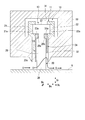
- a shaft seal device 10 is provided between the stationary blade 6 and the rotor 5 as a shaft seal for reducing the amount of combustion gas leaking from the high pressure side to the low pressure side.
- the compressor 2 is coaxially connected to the turbine 4 at the rotor 5, compresses the outside air using the rotation of the turbine 4, and supplies the compressed air to the combustor 3. Similar to the turbine 4, also in the compressor 2, a plurality of moving blades 7 are provided on the rotor 5, and a plurality of stationary blades 6 are provided on the casing 9 side of the compressor 2. They are arranged alternately in the direction Da. Further, a shaft seal device 10 for reducing the amount of compressed air leaking from the high pressure side to the low pressure side is also provided between the stationary blade 6 and the rotor 5.
- compressed air or combustion gas leaks from the high-pressure side to the low-pressure side also in the bearing portion 9 a where the casing 9 of the compressor 2 supports the rotor 5 and the bearing portion 8 a where the casing 8 of the turbine 4 supports the rotor 5.
- a shaft seal device 10 is provided to prevent this.
- the shaft seal device 10 is not limited to application to the gas turbine 1.
- the shaft seal device 10 is widely used in general rotating machines that convert energy into work by rotating the shaft and flowing the fluid, such as large fluid machines such as steam turbines, compressors, water turbines, refrigerators, and pumps. be able to.
- the shaft seal device 10 can also be widely used to suppress the flow of fluid in the axial direction Da.
- FIG. 2 is a diagram viewed from the axial direction Da.
- the shaft seal device 10 includes a plurality (eight in the present embodiment) of seal segments 11 extending in an arc shape.
- a plurality of seal segments 11 are annularly arranged along the circumferential direction Dc.
- a gap t is formed between the circumferential end portions 12 of adjacent seal segments 11 arranged in this way.
- each seal segment 11 will be described with reference to FIG.
- the cutting position of the cross section of the shaft sealing device 10 in FIG. 3 corresponds to the position of the III-III line shown in the shaft sealing device 10 of FIG.
- Each seal segment 11 is inserted in a housing (equivalent to the stationary blade 6, the moving blade 7, and the bearing portions 8 a and 9 a) 30 and installed to prevent leakage of the working fluid in the annular space between the rotor 5 and the housing 30. Is done.
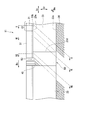
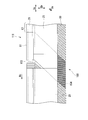
- the seal segment 11 includes a seal body 13, retainers 21 and 22, a high-pressure side plate 23, and a low-pressure side plate 24.
- the seal body 13 includes a plurality of thin plate seal pieces 20, which are metal members, arranged in a multiple manner at minute intervals along the circumferential direction Dc.
- the plurality of thin plate seal pieces 20 are stacked along the circumferential direction Dc (rotational direction Bc) in a partial region of the rotor 5 in the circumferential direction Dc, and as a whole have an arcuate belt shape when viewed from the axial direction Da.
- the retainers 21 and 22 are configured to sandwich the thin plate sealing piece 20 from both sides at the outer peripheral side base end 27 of the thin plate sealing piece 20.
- the cross sections of the retainers 21 and 22 in the circumferential direction Dc are substantially C-shaped. Moreover, the cross section in the axial direction Da of the retainers 21 and 22 is formed in an arc belt shape.
- the high-pressure side plate 23 is sandwiched between the retainer 21 and the high-pressure side edge facing the high-pressure side region of the thin plate seal piece 20. Therefore, the high-pressure side plate 23 extends in the radial direction Dr and the circumferential direction Dc so as to cover the high-pressure side surfaces of the plurality of thin plate sealing pieces 20 from the high-pressure side in the axial direction Da.
- the low pressure side plate 24 is sandwiched between the retainer 22 and the low pressure side edge facing the low pressure side region of the thin plate seal piece 20. Therefore, the low-pressure side plate 24 extends in the radial direction Dr and the circumferential direction Dc so as to cover the low-pressure side surfaces of the plurality of thin plate seal pieces 20 from the low-pressure side in the axial direction Da.
- the thin plate seal piece 20 has a substantially T-side width (width in the axial direction Da) smaller than the width of the outer circumferential base end 27 (width in the axial direction Da). It is made of a thin steel plate. On both side edges, notches 20a and 20b are formed at positions where the width is small. A plurality of adjacent thin plate seal pieces 20 are fixedly connected to each other at the outer peripheral base end 27 by, for example, welding.
- the thin plate seal piece 20 has a predetermined rigidity based on the plate thickness in the circumferential direction Dc. Further, the thin plate seal piece 20 is fixed to the retainers 21 and 22 so that an angle formed between the thin plate seal piece 20 and the peripheral surface of the rotor 5 becomes an acute angle toward the rotation direction Bc. Therefore, the thin plate seal piece 20 extends forward in the rotational direction Bc as it goes inward in the radial direction Dr.
- the tips of the thin plate seal pieces 20 are in contact with the rotor 5 when the rotor 5 is stationary.
- the tip of the thin plate seal piece 20 floats from the outer periphery of the rotor 5 and is in a non-contact state with the rotor 5. For this reason, in this seal segment 11, the wear of each thin plate seal piece 20 is suppressed, and the seal life is extended.
- the high-pressure side plate 23 has a fitting step portion 23a on the outer peripheral side.
- the width of the fitting step portion 23a in the axial direction Da is larger than the width of the high-pressure side plate 23 on the inner peripheral side in the axial direction Da.
- the low-pressure side plate 24 has a fitting step portion 24a on the outer peripheral side.
- the width in the axial direction Da of the fitting stepped portion 24a is larger than the width in the axial direction Da of the low-pressure side plate 24 on the inner peripheral side.
- the fitting step portions 23a and 24a are fitted into the cutout portions 20a and 20b of the thin plate seal piece 20, respectively.
- the retainer 21 has a concave groove 21a on a surface facing one side edge (side edge on the high pressure side) of the outer peripheral side base end 27 of the plurality of thin plate seal pieces 20.
- the retainer 22 has a concave groove 22a on the surface facing the other side edge (the side edge on the low pressure side) at the outer peripheral side base end 27 of the plurality of thin plate seal pieces 20.
- the notch portions 20a and 20b are fitted with a fitting step portion 23a of the high-pressure side plate 23 and a fitting step portion 24a of the low-pressure side plate 24, respectively.
- An annular groove 31 is formed on the inner peripheral wall surface of the housing 30.
- the annular groove 31 has one side edge (a high-pressure side edge) and the other side of the thin seal piece 20 so that the width on the outer peripheral side in the axial direction of the rotor 5 is larger than the width on the inner peripheral side. It is the shape where the level
- the thin plate seal piece 20, the retainers 21 and 22, and the high-pressure side plate 23 are placed in the recessed groove 31 of the housing 30 so that the surface facing the outer peripheral side of the step contacts the inner peripheral surface of the retainers 21 and 22. And the low voltage
- An inner peripheral side end portion 26 of the thin plate seal piece 20 protrudes to the rotor 5 side from the high pressure side plate 23.
- the inner peripheral side end portion 26 of the thin plate seal piece 20 protrudes to the rotor 5 side from the low pressure side plate 24, but the protruding amount is set larger than that of the high pressure side.
- the thin plate seal piece 20 is more exposed to the working fluid G on the low pressure side than on the high pressure side.
- the high-pressure side plate 23 shields a wider area on the side surface of the thin plate sealing piece 20 from the working fluid G.
- the high-pressure side plate 23 is brought into close contact with the side surface 20c of the thin plate seal piece 20 due to the pressure due to the flow of the working fluid G, thereby preventing the working fluid G from greatly flowing into the gaps between the plurality of thin plate seal pieces 20. Therefore, the high-pressure side plate 23 creates an upward flow from the inner peripheral side end portion 26 toward the outer peripheral side base end 27 in the gap portion between the plurality of thin plate seal pieces 20, and the inner peripheral side of the thin plate seal piece 20 by fluid force. The end part 26 is levitated and made non-contact. Further, the low-pressure side plate 24 is pressed by the high-pressure side plate 23 and the thin plate seal piece 20 and is brought into close contact with the low-pressure side wall surface 32 of the inner peripheral wall surface of the housing 30. Since the low-pressure side plate 24 has an inner diameter larger than that of the high-pressure side plate 23, the flow of the gaps between the plurality of thin plate seal pieces 20 is easily flown.
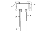
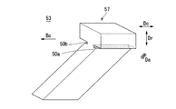
- the seal segment 11 of this embodiment further includes a block body 50 at the front end portion in the rotation direction Bc of the seal body 13.
- the block body 50 and the surrounding structure will be described with reference to FIGS.
- the block body 50 is a metal member.
- the block body 50 includes retainer simulation portions 51 and 52 extending in the circumferential direction Dc from the circumferential direction Dc ends of the retainers 21 and 22, and a seal body simulation portion 53 extending from the retainer simulation portions 51 and 52 inward in the radial direction Dr. Have.
- the retainer simulation portions 51 and 52 extend only from the end portion on the front side in the rotational direction Bc.
- the seal segment 11 of the present embodiment includes the adjustment thin plate seal piece 40 at the end portion on the rear side in the rotational direction Bc among the end portions of the retainers 21 and 22 in the circumferential direction Dc.
- the adjustment thin plate seal piece 40 Since the adjustment thin plate seal piece 40 is exposed from the retainers 21 and 22 and a part of the adjustment thin plate seal piece 40 can be peeled in order, the adjustment thin plate seal piece 40 is necessary depending on the gap between the divided portions between the seal segments 11. The number of thin sheet seal pieces is adjusted. The adjustment thin plate sealing piece 40 whose number has been adjusted shields the gaps between the divided portions between the seal segments 11.
- the high-pressure side plate 23 extends in the radial direction Dr and the circumferential direction Dc so as to cover the high-pressure side surface of the plurality of thin plate sealing pieces 20 as described above. Further, the high-pressure side plate 23 includes an outer diameter side edge 23b that extends in an arc shape in the circumferential direction Dc and an outer diameter side edge portion 23b that extends in the arc direction in the circumferential direction Dc. It has an inner diameter side edge 23c that extends.
- the high-pressure side plate 23 has a front side edge 23d that is an edge on the front side in the rotational direction Bc and extends inward in the radial direction Dr from the outer diameter side edge 23b and is connected to the inner diameter side edge 23c. ing. In the case of the present embodiment, the front edge 23d extends along the radial direction Dr.
- the low-pressure side plate 24 also extends in the radial direction Dr and the circumferential direction Dc so as to cover the high-pressure side surface of the plurality of thin plate seal pieces 20 as described above. Further, the low-pressure side plate 24 is also an outer edge on the outer side in the radial direction Dr and extending in an arc shape in the circumferential direction Dc, and an outer edge on the inner side in the radial direction Dr in an arc shape in the circumferential direction Dc. And an inner diameter side edge extending.
- the low-pressure side plate 24 also has a front edge that is an edge on the front side in the rotational direction Bc and extends inward in the radial direction Dr from the outer diameter side edge and is connected to the inner diameter side edge.
- the high-pressure side plate 23 covers at least part of the axial direction Da high-pressure side of the seal body simulation portion 53
- the low-pressure side plate 24 covers at least part of the axial direction Da low-pressure side of the seal body simulation portion 53. Yes.
- the seal body simulation portion 53 extends to a position aligned with the inner diameter side edge portion 23c of the high pressure side plate 23 in the radial direction Dr. Therefore, the seal body simulation part 53 is not in contact with the rotor 5.
- the retainer simulating parts 51 and 52 have substantially the same shape and dimensions as the retainers 21 and 22 except that the length in the circumferential direction Dc is different. That is, the retainer simulating portions 51 and 52 are configured to sandwich the seal body simulating portion 53 from both sides in the axial direction Da at the outer peripheral side base end 57 of the seal body simulating portion 53.
- the retainer simulating portions 51 and 52 have a substantially C-shaped cross section in the circumferential direction Dc, so that the retainer simulating portions 51 and 52 include a groove 51a and a groove 52a that extend in the circumferential direction, respectively.
- the cross section in the axial direction Da of the retainer simulating portions 51 and 52 is formed in an arc belt shape.
- the seal body simulating portion 53 has a plurality of multiple arrays arranged in the circumferential direction Dc, except that the length in the circumferential direction Dc and the length extending inward in the radial direction Dr are different. It has a shape similar to the contour shape of the entire thin plate seal piece 20. That is, the seal body simulation portion 53 extends along the circumferential direction Dc, has a circular arc shape when viewed from the axial direction Da, and has a cross section in the circumferential direction Dc compared to the width of the outer peripheral base end 57 (width of the axial direction Da). And has a three-dimensional shape that is substantially T-shaped with a small inner circumferential width (width in the axial direction Da).
- the seal body simulation part 53 is a block having a thickness of a plurality of (for example, three or more) thin seal pieces 20 in the circumferential direction Dc.
- the seal body simulating portion 53 is fitted between the high pressure side plate 23 and the low pressure side plate 24 toward the end in the circumferential direction Dc of the retainers 21 and 22, and is fitted between the retainer simulating portions 51 and 52. . Therefore, the seal body simulating portion 53 is fitted like a cap on the end face of the seal body 13 in the rotational direction Bc and protects the thin plate seal piece 20. Moreover, the notch grooves 50a and 50b are fitted in the fitting step portions 23a and 24a, respectively. Therefore, the seal body simulation portion 53 is fitted between the high-pressure side plate 23 and the low-pressure side plate 24, and when fitted between the retainer simulation portions 51 and 52, while being regulated in the radial direction Dr, the circumferential direction Dc. It is possible to slide.
- both side surfaces facing the circumferential direction Dc of the seal body simulation portion 53 are formed between each side surface facing the circumferential direction Dc of the seal body simulation portion 53 and the circumferential surface of the rotor 5 in the rotation direction Bc.
- the inclined surface has an acute angle. Therefore, both side surfaces of the seal body simulating portion 53 facing the circumferential direction Dc extend toward the front side in the rotational direction Bc as going inward in the radial direction Dr.
- the slope of both side faces of the seal body simulating portion 53 facing the circumferential direction Dc may be any slope as long as the slope is generally along the slope of the plate surface of the thin seal piece 20.
- the inclination of both side faces of the seal body simulating portion 53 facing the circumferential direction Dc is simulated and inclined so as to follow the inclination of the plate surface of the thin plate seal piece 20 when preload is applied to the thin plate seal piece 20. Also good.
- both side surfaces facing the circumferential direction Dc of the seal body simulation portion 53 may be curved surfaces as long as they follow the plate surface of the thin plate seal piece 20.
- the metal is formed at the front end in the rotational direction Bc of the seal body 13, which is a divided portion between the seal segments 11, that is, a divided portion between the high-pressure side plates 23 of the seal segments 11 adjacent in the circumferential direction Dc.
- the seal body simulation part 53 which consists of these blocks is provided.
- the seal body simulation portion 53 may be a metal block having a cavity inside, and as another modification, the seal body simulation portion 53 is a metal It may be a box-shaped block.
- the seal body simulating portion 53 that does not contact the rotor 5 instead of the thin plate seal piece at the divided portion between the seal segments 11, it is not necessary to provide the thin plate seal piece at the divided portion between the seal segments 11. Therefore, wear of the thin plate seal piece is suppressed.
- a thin plate seal piece is provided on the inner side in the circumferential direction Dc from the end of the seal segment 11, and the performance of the floating characteristic of the thin plate seal piece is maintained.
- the seal body simulation portion 53 protects the thin plate seal piece 20 by being fitted like a cap on the end surface of the seal body 13 in the circumferential direction Dc.
- the seal body simulation portion 53 Since the seal body simulation portion 53 has a plurality of thicknesses of the thin plate seal pieces 20 in the circumferential direction Dc, the seal body simulation portion 53 is thicker than the thin plate seal pieces 20 in the circumferential direction Dc and has high rigidity. Have. For this reason, wear at the divided portion between the seal segments 11 is suppressed, and fluttering generated in the thin plate seal piece 20 can be suppressed.
- seal segment 11 of the present embodiment covers at least part of the axial direction Da high pressure side of the seal body simulation portion 53 with the high pressure side plate 23, and the shaft of the seal body simulation portion 53 with the low pressure side plate 24.
- the direction Da covers at least part of the low pressure side.
- the seal body simulation portion 53 is provided at the front end portion in the rotational direction Bc of the seal body 13. That is, the high-pressure side plate 23 further extends from the side surfaces of the plurality of thin plate seal pieces 20 and covers at least a part of the seal body simulating portion 53 on the high-pressure side in the axial direction Da. If at least a part of the axial direction Da high-pressure side of the seal body simulating portion 53 is covered, the working fluid G that wraps around even if the working fluid G wraps around the inside of the high-pressure side plate 23 in the axial direction Da. Only flows around the seal body simulation portion 53.
- the seal segment 11 of the present embodiment can suppress the working fluid G from flowing around the plurality of thin plate seal pieces 20, so that the flow of the working fluid G in the axial direction Da is difficult to leak, and the plurality of thin plate seals In the piece 20, it can suppress that fluttering generate
- the rear portion in the rotational direction Bc is covered with the front portion in the rotational direction Bc of the high-pressure side plate 23 in the axial direction Da high-pressure side of the seal body simulation portion 53. If the rear portion in the rotation direction Bc of the seal body simulation portion 53 is covered with the front portion in the rotation direction Bc of the high-pressure side plate 23, the degree of freedom of the plate surface shape in the front portion in the rotation direction Bc of the high-pressure side plate 23 is increased. Therefore, the plate surface shape on the front side in the rotation direction Bc of the high-pressure side plate 23 is not necessarily matched with the axial Da side shape of the plurality of thin plate seal pieces or the axial Da side shape of the seal body simulation portion 53.
- the plate surface shape on the front side in the rotation direction Bc of the high-pressure side plate 23 is a plate surface in which the angle formed between the front edge 23d and the peripheral surface of the rotor 5 is an acute angle in the rotation direction Bc. There is no need to be shaped.
- the front side edge 23d and the peripheral surface of the rotor 5 are formed in the rotational direction Bc by making the shape of the high-pressure side plate 23 so that the front edge 23d extends along the radial direction Dr.
- the corners formed between are large. Therefore, as the acute angle of the plate surface shape increases, the rigidity of the high-pressure side plate 23 increases, and fluttering is suppressed in the high-pressure side plate 23.
- the seal segment 11 of the present embodiment is excellent in terms of quality maintenance and production efficiency as described below.
- a small portion of the seal body simulation portion 53 can be fitted into the majority of the seal body 13 manufactured by a normal manufacturing process. That is, the seal body simulating portion 53 can be provided only at the end in the circumferential direction Dc after the majority of the seal segment 11 is manufactured with a large number of thin seal pieces having the same thickness. Accordingly, the seal body simulation part 53 is provided only in the vicinity of the split part of the seal segment 11 while maintaining the manufacturing process for assembling the thin seal pieces having the same thickness (which is a normal manufacturing process), so that the quality is maintained and the production is maintained. Efficiency is improved.
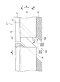
- the seal segment of the present embodiment is basically the same as that of the first embodiment, except that the seal body simulation portion includes a contact seal.
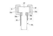
- the seal segment 111 of this embodiment further includes a block body 150 at the front end portion in the rotational direction Bc of the seal body 13.
- the structure of the block body 150 and its periphery will be described with reference to FIG.
- the block body 150 includes retainer simulation portions 51 and 52 that extend further in the circumferential direction Dc from the front end portion in the rotational direction Bc of the retainers 21 and 22, and a seal body simulation portion 153 that extends from the retainer simulation portions 51 and 52 inward in the radial direction Dr. And a contact seal 154.
- the contact seal 154 is provided in the seal body simulation portion 153 and extends from the inner end in the radial direction Dr of the seal body simulation portion 153 to the inner side in the radial direction Dr. The gap between them is filled. Moreover, the seal body simulation part 153 is a block having a thickness of a plurality of (for example, three or more) thin seal pieces 20 in the circumferential direction Dc. In this embodiment, a brush seal is used for the contact seal 154.
- the seal body simulation part 153 Since the seal body simulation part 153 has a block shape, it cannot be brought into direct contact with the peripheral surface of the rotor 5. For this reason, it is necessary to provide a gap between the inner end of the seal body simulating portion 153 in the radial direction Dr and the rotor 5, and the working fluid G leaks not a little.
- the contact seal 154 by using the contact seal 154, the inner end of the seal body simulation portion 153 in the radial direction Dr and the rotor 5 are not in contact with each other. For this reason, a gap can be filled between the inner end of the seal body simulating portion 153 in the radial direction Dr and the rotor 5. Therefore, the working fluid G can suppress leakage.
- a seal method using a thin seal piece that is a seal method having high followability to the deviation of the axis Ax of the rotor 5 is replaced with a brush seal that is a seal method having high followability to the deviation of the axis Ax of the rotor 5.
- a brush seal that is a seal method having high followability to the deviation of the axis Ax of the rotor 5.
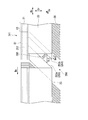
- the seal segment of the present embodiment is basically the same as that of the first embodiment, except that the seal body simulation part is divided into a main seal body simulation part and a sub seal body simulation part.
- the seal segment 211 of this embodiment further includes a block body 250 at the front end portion in the rotation direction Bc of the seal body 13.
- the structure of the block body 250 and its periphery will be described with reference to FIG.
- the block body 250 includes retainer simulation portions 51 and 52 that extend further in the circumferential direction Dc from the front end portion in the rotational direction Bc of the retainers 21 and 22, and a seal body simulation portion 253 that extends from the retainer simulation portions 51 and 52 inward in the radial direction Dr. Have
- the seal body simulation portion 253 includes a main seal body simulation portion 253a and a sub seal body simulation portion 253b that protrude from the outer peripheral base end 257 and extend radially inward.
- the seal body simulation part 253 has a slit SL2 extending from the inner peripheral end of the outer peripheral side base end 257 in the radial direction Dr toward the inner side of the radial direction Dr.
- the seal body simulation unit 253 is configured such that, in the circumferential direction Dc, a part of a block having a thickness of a plurality of thin seal pieces 20 (for example, 3 or more) is formed by a slit SL2 so that the main seal body simulation unit 253a and the sub seal body It has a shape divided into a simulation unit 253b.
- the sub seal body simulation portion 253b has a smaller rigidity in the circumferential direction Dc, for example, by reducing the thickness in the circumferential direction Dc than the main seal body simulation portion 253a.
- the sub seal body simulation part 253b has elasticity in the peristaltic direction Del along the circumferential direction Dc with respect to the outer peripheral side base end 257 by reducing rigidity in the circumferential direction Dc, and can be bent. It deform
- the thickness in the circumferential direction Dc of the sub seal body simulation portion 253b is made smaller than that of the main seal body simulation portion 253a.
- the main seal is compared with the sub seal body simulation portion 253b. You may make thickness of the circumferential direction Dc of the body simulation part 253a small. In this case, by bending the main seal body simulation portion 253a in the swing direction Del, the seal body simulation portion 253 can follow the behavior of the thin plate seal piece 20 of the seal segment 211 adjacent to the front in the rotation direction Bc.
- the seal segment of this embodiment is basically the same as that of the third embodiment, except that an elastic member is provided in the slit.
- the seal segment 311 of this embodiment further includes a block body 350 at the front end portion in the rotation direction Bc of the seal body 13.
- the block body 350 and the surrounding structure will be described with reference to FIG.
- the block body 350 of this embodiment includes an elastic member 355 between the main seal body simulation portion 253a and the sub seal body simulation portion 253b.
- the elastic member 355 is a spring element, for example, and uses a coil spring, a leaf spring, or the like. Due to the elasticity of the elastic member in addition to the elasticity of the sub seal body simulation part 253b itself, the sub seal body simulation part 253b has elasticity in the peristaltic direction Del along the circumferential direction Dc with respect to the outer peripheral side base end 257 and bends. be able to. For this reason, it deform
- the bending of the sub seal body simulation portion 253b is adjusted so as to follow the behavior of the thin plate seal piece 20.
- the elastic member 355 may be provided at a plurality of locations along the slit SL2.
- the number of seal segments included in the shaft seal device of the present embodiment is eight, but is not limited thereto, and may be any of two to seven, or even nine or more.
- the adjustment thin plate seal piece 40 is provided, but the adjustment thin plate seal piece 40 may not be provided if it is not necessary to shield the gaps between the divided portions between the seal segments.
- the end portion on the rear side in the rotational direction Bc of the retainer simulating portions 51 and 52 and the end portion on the front side in the rotational direction Bc of the retainers 21 and 22 are joined by welding or brazing, respectively. It may be joined by screwing.
- the retainers 21 and 22 are not joined to the retainer simulation parts 51 and 52, respectively, but the retainer simulation part 51 and the retainer 21 are integrally formed, and the retainer simulation part 52 and the retainer 22 are integrally formed. May be.
- the retainer simulating portions 51 and 52 extend from the end portion on the front side in the rotational direction Bc, and the retainer simulating portions 51 and 52 extend to the end portion on the front side in the rotational direction Bc. 52 is provided.
- the retainer simulation portions 51 and 52 extend from the end portion on the rear side in the rotation direction Bc, and the retainer simulation portions 51 and 52 extend to the end portion on the rear side in the rotation direction Bc. May be provided. In that case, various functions act on the thin plate seal piece 20 behind the rotation direction Bc.
- the above-described seal segment and rotating machine can suppress the degradation of the floating characteristics of the thin plate seal piece and fluttering that occurs in the thin plate seal piece.
Landscapes
- Engineering & Computer Science (AREA)
- General Engineering & Computer Science (AREA)
- Mechanical Engineering (AREA)
- Chemical & Material Sciences (AREA)
- Combustion & Propulsion (AREA)
- Sealing Devices (AREA)
- Turbine Rotor Nozzle Sealing (AREA)
- Structures Of Non-Positive Displacement Pumps (AREA)
Priority Applications (4)
| Application Number | Priority Date | Filing Date | Title |
|---|---|---|---|
| EP17795936.8A EP3438512B1 (en) | 2016-05-09 | 2017-04-21 | Seal segment and rotary machine |
| KR1020187031936A KR102090893B1 (ko) | 2016-05-09 | 2017-04-21 | 시일 세그먼트 및 회전 기계 |
| US16/097,692 US11293350B2 (en) | 2016-05-09 | 2017-04-21 | Seal segment and rotary machine |
| CN201780027242.1A CN109073088B (zh) | 2016-05-09 | 2017-04-21 | 密封段及旋转机械 |
Applications Claiming Priority (2)
| Application Number | Priority Date | Filing Date | Title |
|---|---|---|---|
| JP2016-093906 | 2016-05-09 | ||
| JP2016093906A JP6631837B2 (ja) | 2016-05-09 | 2016-05-09 | シールセグメント及び回転機械 |
Publications (1)
| Publication Number | Publication Date |
|---|---|
| WO2017195575A1 true WO2017195575A1 (ja) | 2017-11-16 |
Family
ID=60266550
Family Applications (1)
| Application Number | Title | Priority Date | Filing Date |
|---|---|---|---|
| PCT/JP2017/016078 Ceased WO2017195575A1 (ja) | 2016-05-09 | 2017-04-21 | シールセグメント及び回転機械 |
Country Status (6)
| Country | Link |
|---|---|
| US (1) | US11293350B2 (enExample) |
| EP (1) | EP3438512B1 (enExample) |
| JP (1) | JP6631837B2 (enExample) |
| KR (1) | KR102090893B1 (enExample) |
| CN (1) | CN109073088B (enExample) |
| WO (1) | WO2017195575A1 (enExample) |
Families Citing this family (2)
| Publication number | Priority date | Publication date | Assignee | Title |
|---|---|---|---|---|
| FR3071281B1 (fr) * | 2017-09-18 | 2022-01-07 | Thermodyn | Machine tournante comprenant un systeme d'amortissement d'un joint d'etancheite |
| JP7566201B2 (ja) * | 2022-03-04 | 2024-10-11 | 三菱重工業株式会社 | 軸シール装置及び回転機械 |
Citations (3)
| Publication number | Priority date | Publication date | Assignee | Title |
|---|---|---|---|---|
| WO2008004590A1 (en) * | 2006-07-06 | 2008-01-10 | Eagle Industry Co., Ltd. | Brush seal device |
| WO2010146805A1 (ja) * | 2009-06-16 | 2010-12-23 | 三菱重工業株式会社 | 軸シール及びこれを備えた回転機械 |
| WO2015115400A1 (ja) * | 2014-01-28 | 2015-08-06 | 三菱重工業株式会社 | 軸シール装置及び回転機械 |
Family Cites Families (36)
| Publication number | Priority date | Publication date | Assignee | Title |
|---|---|---|---|---|
| CA2303151C (en) | 1998-07-13 | 2004-08-31 | Mitsubishi Heavy Industries, Ltd. | Shaft seal and turbine using the shaft seal |
| CA2359933C (en) * | 2001-02-08 | 2006-03-14 | Mitsubishi Heavy Industries, Ltd. | Shaft seal and gas turbine |
| JP3702212B2 (ja) * | 2001-09-28 | 2005-10-05 | 三菱重工業株式会社 | 軸シール機構及びタービン |
| JP3593082B2 (ja) * | 2001-10-09 | 2004-11-24 | 三菱重工業株式会社 | 軸シール機構及びタービン |
| JP4009555B2 (ja) * | 2003-05-20 | 2007-11-14 | イーグル・エンジニアリング・エアロスペース株式会社 | 板ブラシシール装置 |
| CN1324221C (zh) * | 2003-05-21 | 2007-07-04 | 三菱重工业株式会社 | 轴密封机构 |
| CN100396885C (zh) * | 2003-05-21 | 2008-06-25 | 三菱重工业株式会社 | 轴密封机构、轴密封机构的组装结构和大型流体机械 |
| DE102004016173A1 (de) * | 2004-03-30 | 2005-10-20 | Alstom Technology Ltd Baden | Lamellendichtung, insbesondere für eine Gasturbine, sowie Verfahren zu deren Herstellung |
| JP3950455B2 (ja) * | 2004-04-20 | 2007-08-01 | 三菱重工業株式会社 | 軸シール用部材及び軸シール機構及び大型流体機械 |
| GB0417613D0 (en) * | 2004-08-07 | 2004-09-08 | Rolls Royce Plc | A leaf seal arrangement |
| JP3917993B2 (ja) * | 2004-08-10 | 2007-05-23 | 三菱重工業株式会社 | 軸シール機構及び軸シール機構をステータに取り付ける構造並びにこれらを備えたタービン。 |
| US7413194B2 (en) * | 2004-10-28 | 2008-08-19 | Rolls-Royce Plc | Pressure balanced annular seal |
| DE102004059858A1 (de) * | 2004-12-11 | 2006-06-29 | Alstom Technology Ltd | Lamellendichtung, insbesondere für eine Gasturbine |
| JP3970298B2 (ja) * | 2005-11-10 | 2007-09-05 | 三菱重工業株式会社 | 軸シール機構 |
| US7419164B2 (en) * | 2006-08-15 | 2008-09-02 | General Electric Company | Compliant plate seals for turbomachinery |
| JP5028918B2 (ja) * | 2006-09-11 | 2012-09-19 | 富士電機株式会社 | 回転物体用シール装置 |
| FR2907356B1 (fr) * | 2006-10-20 | 2009-05-22 | Hef Soc Par Actions Simplifiee | Piece de frottement en milieu lubrifie et dont la surface est texturee. |
| JP4625438B2 (ja) | 2006-11-16 | 2011-02-02 | 三菱重工業株式会社 | 回転機械の軸シール装置 |
| JP2008261473A (ja) | 2007-03-19 | 2008-10-30 | Mitsuboshi Belting Ltd | 動力伝動ベルト |
| GB0707224D0 (en) | 2007-04-14 | 2007-05-23 | Rolls Royce Plc | A seal arrangement |
| US7976026B2 (en) * | 2007-04-30 | 2011-07-12 | General Electric Company | Methods and apparatus to facilitate sealing in rotary machines |
| US7744092B2 (en) * | 2007-04-30 | 2010-06-29 | General Electric Company | Methods and apparatus to facilitate sealing in rotary machines |
| GB2461507B (en) | 2008-06-30 | 2010-09-08 | Rolls Royce Plc | A sealing device |
| US8262349B2 (en) * | 2008-12-22 | 2012-09-11 | General Electric Company | Adaptive compliant plate seal assemblies and methods |
| US8250756B2 (en) * | 2009-02-20 | 2012-08-28 | General Electric Company | Method of manufacture of compliant plate seals |
| DE102009015122A1 (de) * | 2009-03-31 | 2010-10-14 | Alstom Technology Ltd. | Lamellendichtung für eine Strömungsmaschine |
| US8152462B1 (en) * | 2009-08-19 | 2012-04-10 | Florida Turbine Technologies, Inc. | Card seal with conical flexible seal |
| GB0922074D0 (en) * | 2009-12-18 | 2010-02-03 | Rolls Royce Plc | A leaf seal assembly |
| JP5473685B2 (ja) * | 2010-03-10 | 2014-04-16 | 三菱重工業株式会社 | 軸シール装置及び軸シール装置を備える回転機械 |
| US8474827B2 (en) * | 2010-06-11 | 2013-07-02 | Cmg Tech, Llc | Film riding pressure actuated leaf seal assembly |
| US9206904B2 (en) * | 2010-07-08 | 2015-12-08 | Siemens Energy, Inc. | Seal including flexible seal strips |
| US8382120B2 (en) * | 2010-08-31 | 2013-02-26 | General Electric Company | Method and apparatus for compliant plate seals |
| JP5804893B2 (ja) * | 2011-10-26 | 2015-11-04 | 三菱重工業株式会社 | 軸シール装置及びこれを備える回転機械 |
| JP5931450B2 (ja) * | 2012-01-13 | 2016-06-08 | 三菱重工業株式会社 | 軸シール装置及びこれを備える回転機械 |
| JP5851890B2 (ja) * | 2012-03-08 | 2016-02-03 | 三菱重工業株式会社 | 軸シール装置 |
| JP6678062B2 (ja) | 2016-05-09 | 2020-04-08 | 三菱日立パワーシステムズ株式会社 | シールセグメント及び回転機械 |
-
2016
- 2016-05-09 JP JP2016093906A patent/JP6631837B2/ja active Active
-
2017
- 2017-04-21 WO PCT/JP2017/016078 patent/WO2017195575A1/ja not_active Ceased
- 2017-04-21 CN CN201780027242.1A patent/CN109073088B/zh active Active
- 2017-04-21 US US16/097,692 patent/US11293350B2/en active Active
- 2017-04-21 EP EP17795936.8A patent/EP3438512B1/en not_active Not-in-force
- 2017-04-21 KR KR1020187031936A patent/KR102090893B1/ko not_active Expired - Fee Related
Patent Citations (3)
| Publication number | Priority date | Publication date | Assignee | Title |
|---|---|---|---|---|
| WO2008004590A1 (en) * | 2006-07-06 | 2008-01-10 | Eagle Industry Co., Ltd. | Brush seal device |
| WO2010146805A1 (ja) * | 2009-06-16 | 2010-12-23 | 三菱重工業株式会社 | 軸シール及びこれを備えた回転機械 |
| WO2015115400A1 (ja) * | 2014-01-28 | 2015-08-06 | 三菱重工業株式会社 | 軸シール装置及び回転機械 |
Also Published As
| Publication number | Publication date |
|---|---|
| KR20180127484A (ko) | 2018-11-28 |
| EP3438512A1 (en) | 2019-02-06 |
| CN109073088B (zh) | 2020-06-05 |
| CN109073088A (zh) | 2018-12-21 |
| US11293350B2 (en) | 2022-04-05 |
| JP2017203470A (ja) | 2017-11-16 |
| US20190162120A1 (en) | 2019-05-30 |
| KR102090893B1 (ko) | 2020-03-18 |
| JP6631837B2 (ja) | 2020-01-15 |
| EP3438512B1 (en) | 2020-05-27 |
| EP3438512A4 (en) | 2019-05-08 |
Similar Documents
| Publication | Publication Date | Title |
|---|---|---|
| CN103842695B (zh) | 轴密封装置及具备该轴密封装置的旋转机械 | |
| JP5174241B2 (ja) | 軸シール及びこれを備えた回転機械 | |
| US9677669B2 (en) | Shaft seal device and rotary machine | |
| US10024434B2 (en) | Shaft seal device and rotary machine | |
| WO2013105606A1 (ja) | 軸シール装置及びこれを備える回転機械 | |
| JP6631837B2 (ja) | シールセグメント及び回転機械 | |
| KR102168843B1 (ko) | 시일 세그먼트 및 회전 기계 | |
| JP6876012B2 (ja) | シールセグメント及び回転機械 | |
| US10927765B2 (en) | Seal segment and rotary machine |
Legal Events
| Date | Code | Title | Description |
|---|---|---|---|
| WWE | Wipo information: entry into national phase |
Ref document number: 2017795936 Country of ref document: EP |
|
| ENP | Entry into the national phase |
Ref document number: 20187031936 Country of ref document: KR Kind code of ref document: A |
|
| NENP | Non-entry into the national phase |
Ref country code: DE |
|
| ENP | Entry into the national phase |
Ref document number: 2017795936 Country of ref document: EP Effective date: 20181031 |
|
| 121 | Ep: the epo has been informed by wipo that ep was designated in this application |
Ref document number: 17795936 Country of ref document: EP Kind code of ref document: A1 |