WO2017195485A1 - 留め具 - Google Patents
留め具 Download PDFInfo
- Publication number
- WO2017195485A1 WO2017195485A1 PCT/JP2017/012729 JP2017012729W WO2017195485A1 WO 2017195485 A1 WO2017195485 A1 WO 2017195485A1 JP 2017012729 W JP2017012729 W JP 2017012729W WO 2017195485 A1 WO2017195485 A1 WO 2017195485A1
- Authority
- WO
- WIPO (PCT)
- Prior art keywords
- leg
- portions
- shaft
- shaft portions
- elastic engagement
- Prior art date
- Legal status (The legal status is an assumption and is not a legal conclusion. Google has not performed a legal analysis and makes no representation as to the accuracy of the status listed.)
- Ceased
Links
Images











Classifications
-
- F—MECHANICAL ENGINEERING; LIGHTING; HEATING; WEAPONS; BLASTING
- F16—ENGINEERING ELEMENTS AND UNITS; GENERAL MEASURES FOR PRODUCING AND MAINTAINING EFFECTIVE FUNCTIONING OF MACHINES OR INSTALLATIONS; THERMAL INSULATION IN GENERAL
- F16B—DEVICES FOR FASTENING OR SECURING CONSTRUCTIONAL ELEMENTS OR MACHINE PARTS TOGETHER, e.g. NAILS, BOLTS, CIRCLIPS, CLAMPS, CLIPS OR WEDGES; JOINTS OR JOINTING
- F16B19/00—Bolts without screw-thread; Pins, including deformable elements; Rivets
Definitions
- the present invention relates to a fastener that is inserted into a mounting hole and fixed.
- a mounting hole is formed in a vehicle body panel or the like of an automobile, and a trim board or the like is attached to the vehicle body panel or the like via a fastener that is inserted into the mounting hole and fixed.
- a fastener (so-called hole plug) may be attached to close a hole formed in the vehicle body panel or the like.
- Patent Document 1 includes a head that engages with a mounting member, and a leg that extends from the head and is mounted through a mounting hole of a mounted member.
- the portion has a flange adjacent to the head and abutting against one surface of the mounted member, and a shaft portion extending from the flange, and the shaft portion is an elastic member that is locked in a mounting hole of the mounted member.
- a clip having a stop is described.
- the shaft portion is extended in the circumferential direction so as to be opposite to each other from a pair of elongated plate-like column portions eccentrically disposed adjacent to the center of the leg portion and the outer diameter side end portions of the respective column portions. It has a pair of elastic locking portions and has a substantially S-shaped cross section. In addition, this axial part is formed by a pair of right-and-left division
- the clip of Patent Document 1 is such that the base end side of each column portion of the shaft portion and each elastic locking portion is connected to the back surface of the flange, and the distal end portion of each column portion and each elastic locking portion. Since the sides are also connected to each other via the connecting portion, when the leg portion is inserted into the mounting hole of the mounted member, the elastic locking portion pressed against the inner periphery of the mounting hole becomes difficult to bend and the leg portion is inserted. There was an inconvenience that it was difficult to do. Further, since the elastic locking portion is difficult to bend, there is also a problem that it is difficult to cope with a change in the inner diameter of the mounting hole of the mounted member.
- an object of the present invention is to provide a fastener that can improve the insertability into the mounting hole and can also widen the applicable width with respect to the inner diameter of the mounting hole.
- the present invention provides a fastener that is inserted into a mounting hole and attached thereto, the head being disposed on the front side of the mounting hole, and the head connected to and extending from the head.
- a leg portion inserted and locked in the hole, and the leg portion includes a plurality of shaft portions extending from the back surface of the head with a gap therebetween, and the plurality of shaft portions.
- an elastic engagement piece that extends from at least a pair of shaft portions in the outer diameter direction and / or circumferential direction of the leg portion and engages with a rear peripheral edge of the mounting hole, and separates the plurality of shaft portions.
- the gap to be formed is formed so as to penetrate the front end portion of the leg portion in the insertion direction into the mounting hole and / or the head portion in the axial direction.
- the gap separating the plurality of shaft portions of the leg portion penetrates the tip portion of the leg portion in the insertion direction into the mounting hole and / or the head portion in the axial direction. Since it is formed, when the leg portion is inserted into the mounting hole of the mounted member and the elastic engagement piece is pressed to the inner periphery of the mounting hole to bend and deform, the shaft portion pressed through the elastic engagement piece The leg can be easily bent and the entire leg portion can be easily bent. As a result, the insertion resistance of the leg portion to the mounting hole can be reduced and the insertability can be improved. Also, not only the elastic engagement piece but also the shaft part is easily bent, so that the leg part can be inserted and locked even if the inner diameter of the mounting hole varies somewhat. The width can be increased.
- FIG. 5 is a cross-sectional view taken along the line AA in FIG. 4. It is explanatory drawing which shows the state which attached the attachment member to the to-be-attached member via the fastener.
- A) is a cross-sectional view of FIG. 7,
- (b) is a cross-sectional view when the inner diameter of the mounting hole is smaller than (a).
- FIG. 21 is a cross-sectional view taken along the line EE in FIG. 20. It is sectional explanatory drawing which shows the state which attached the attachment member to the to-be-attached member via the fastener.
- This fastener is inserted into a mounting hole formed in a predetermined member and fixed. As shown in FIGS. 1 and 7, the fastener 10 in this embodiment is locked to a mounting seat 7 formed on the mounting member 5 and has a circular mounting formed on the mounted member 1, for example. It is inserted into the hole 3 and fixed, and is used to attach the attachment member 5 to the attachment member 1.
- the “back side of the mounting hole” in the present invention is one side portion in the thickness direction of the member in which the mounting hole is formed (here, the mounted member 1), and is the head placement side of the fastener. Means the other side.
- Examples of the mounted member 1 include a vehicle body panel and a vehicle body frame, and examples of the mounting member 5 include a trim board, a cover, a garnish, an assist grip, a bumper, a lamp, and an insulator (soundproof material). Although it is mentioned, it is not limited to these.
- the mounting seat 7 of the mounting member 5 has a frame shape in which one side portion (receiving side of the fastener 10) is opened and a locking groove 8 is formed on the bottom surface.
- the head 20 can be held.
- a circular insertion hole may be provided in the attachment member 5 and the head 20 of the fastener 10 may be engaged with the front side, and there is no particular limitation.
- the fastener may be used not only for the above-mentioned purposes but also for closing the mounting hole (so-called hole plug), and is not particularly limited.
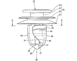
- the fastener 10 includes a head 20 disposed on the front side of the mounting hole 3 of the mounted member 1, and is connected to the head 20 and extends to the mounting hole 3. And a leg portion 30 that is inserted into and locked to.
- the head 20 in this embodiment includes a neck 21 inserted into the locking groove 8 of the mounting seat 7 of the mounting member 5 and a circle extending from the outer periphery of the tip of the neck 21.
- the outer periphery is composed of a third flange portion 27 that spreads in a skirt shape obliquely outward toward the leg portion 30 side.
- the neck portion 21 of the head 20 is inserted into the locking groove 8 of the mounting seat 7, and the mounting seat 7 is sandwiched between the first flange portion 23 and the second flange portion 25, so that the fastener 10 is attached to the mounting seat 7. Is mounted (see FIG. 7).
- the structure of the head is not limited to the above-described aspect, and may be any shape that engages with the front side periphery of the attachment hole formed in the predetermined member.
- the leg portion 30 of this embodiment includes a plurality of shaft portions 31 that extend from the back surface of the head 20 with a gap 35 therebetween.
- the elastic engagement piece 40 extends in the circumferential direction of the leg portion 30 from each shaft portion 31 and engages with the rear side periphery of the mounting hole 3.
- an elastic engagement piece in a leg part you may extend in the outer-diameter direction of a leg part and / or the circumferential direction from at least a pair of shaft part among several shaft parts (About this aspect) Will be described later in the sixth embodiment), and is not particularly limited.
- the plurality of shaft portions 31 in this embodiment are composed of a pair of third flange portions 27 of the head 20 extending from the flat back surface, and the pair of shaft portions 31, 31. A gap 35 is provided between them.
- each shaft portion 31 has a plurality of shaft portions 31 (a plurality of shaft portions 31) when the leg portion 30 is viewed in a cross section orthogonal to the axial direction (hereinafter, also referred to as a “cross section of the leg portion 30”).
- An end portion 32 on the inner peripheral side (the inner peripheral side of the leg portion 30) of the shaft portion 31), and an end portion 33 on the outer peripheral side (the outer peripheral side of the leg portion 30) of each shaft portion 31 (the plurality of shaft portions 31); are arranged on a straight line L passing through the center C of the leg 30.
- the end on the head 20 side of each shaft portion 31 forms a diameter-expanded portion 34 that is slightly larger in diameter than the other portions of the shaft portion 31. 34 is connected to the third flange portion 27 of the head 20.
- the gap 35 that separates the plurality of shaft portions 31 has a common inner peripheral side of each shaft portion 31 (the plurality of shaft portions 31) in a cross section orthogonal to the axial direction of the leg portion 30.
- the inner periphery (here, the end portion 32 on the inner periphery side) of each shaft portion 31 (the plurality of shaft portions 31) has an arc shape.
- leg part 30 of this embodiment although it has a pair of axial parts 31, 31, you may have a shaft part of three, four pieces, or more, for example. (The four shaft portions will be described in an embodiment described later), and it is only necessary to have a gap between them. Further, the shape of each shaft portion may be a cross-sectional long plate shape or a cross-sectional circular shape, and is not particularly limited.
- the elastic engagement piece 40 in this embodiment is formed from end portions 33, 33 on the outer peripheral side of the pair of shaft portions 31, 31 when the cross section of the leg portion 30 is viewed.
- a pair of elastic engagement pieces 40 which are curved so as to spread in the outer diameter direction along the circumferential direction of the legs 30 and extend through the gaps 37 with respect to the shafts 31, respectively. 40 is arranged point-symmetrically with respect to the center C of the leg 30. Note that the gaps 37 and 37 communicate with a gap 35 provided between the pair of shaft portions 31 and 31 (see FIG. 6).
- each elastic engagement piece 40 an end edge 41 on the head 20 side in the axial direction of the leg 30 is separated from the head 20 (see FIGS. 3 to 5). Further, on the outer peripheral surface of each elastic engagement piece 40 on the end edge 41 side, there is provided an engaging portion 43 that bulges so as to engage with the rear peripheral edge of the mounting hole 3 (see FIG. 7). . Furthermore, a portion of each elastic engagement piece 40 closer to the end edge 41 than the engagement portion 43 forms an insertion portion 44 that is inserted into the inner periphery of the attachment hole 3 (see FIG. 7). As shown in FIGS.
- each elastic engagement piece 40 on the insertion direction side of the leg portion 30 on the side opposite to the head 20 in the axial direction of the leg portion 30
- the leg portion 30 is provided.
- the cut portions 46 are formed so that the extension length from the shaft portion 31 becomes shorter toward the front end of the shaft. Thereby, the elastic engagement piece 40 is inserted when the leg portion 30 is inserted into the mounting hole 3. It is easy to bend.
- the elastic engagement piece 40 of this embodiment has a shape extending from the shaft portion 31 in the circumferential direction and the outer diameter direction of the leg portion 30, but as the elastic engagement piece, the periphery of the leg portion from the shaft portion is used.
- the plurality of shaft portions 31 are connected to the distal end side of the leg portion 30 in the insertion direction by a connecting portion 50.
- the pair of shaft portions 31, 31 and the pair of elastic engagement pieces 40, 40 are connected to each other in the insertion direction front end side of the leg portion 30 by the connecting portion 50.
- the connecting portion 50 has a tapered shape that gradually decreases in diameter toward the distal end side in the insertion direction of the leg portion 30.
- the outer periphery of the connecting portion 50 on the insertion direction side of the leg portion 30 is positioned at a position aligned with the distal end portion of the pair of shaft portions 31, 31 in the insertion direction of the leg portion 30.
- the lightening recesses 51 and 51 are formed.
- the gap 35 that separates the plurality of shaft portions 31 penetrates the tip portion 30 of the leg portion 30 in the insertion direction into the mounting hole 3 and / or the head portion 20 in the axial direction. It is formed as follows.
- the gap 35 that separates the pair of shaft portions 31 and 31 is formed so as to penetrate the head portion 20 in the axial direction. That is, the gap 35 separating the pair of shaft portions 31, 31 passes through the centers of the third flange portion 27, the second flange portion 25, the neck portion 21, and the first flange portion 23 of the head 20, respectively. 10 has a shape communicating with the outside.
- the above-mentioned gap does not penetrate the head 20 side but penetrates the distal end side in the insertion direction 3 of the leg 30 into the mounting hole 3, or penetrates both the head 20 and the distal end side in the insertion direction of the leg 30.
- the inner circumferential surface of the gap 35 has a tapered surface shape in which the distal end side in the insertion direction of the leg portion 30 is narrow and gradually becomes wider toward the upper end opening through which the head 20 penetrates. Yes.
- the above fastener 10 includes an outer peripheral shape of the head 20, a pair of shaft portions 31, 31 of the leg portion 30, a pair of elastic engagement pieces 40,
- the outer circumference and inner circumference shape of 40 can be formed by molds S1 and S2 that move in a direction perpendicular to the axis of the leg portion 30, and the inner circumference shape of the pair of shaft portions 31, 31 and the head 20
- the inner peripheral shape and the gap 35 can be formed by a mold S3 (see FIG. 5) that moves in the axial direction of the leg portion 30.
- the neck portion 21 of the head portion 20 of the fastener 10 is inserted into the locking groove 8 of the mounting seat 7 of the mounting member 5 (see FIG. 1), and the mounting seat 7 is inserted into the first flange portion 23 and the second flange portion.
- the fastener 10 is mounted on the mounting seat 7 by being sandwiched at 25 (see FIG. 7).
- the leg 30 of the fastener 10 is inserted into the mounting hole 3 of the mounted member 1 from the front side. Then, the pair of elastic locking pieces 40, 40 are pressed on the inner periphery of the mounting hole 3, and the pair of elastic engagement pieces 40, 40 are bent toward the inner side of the leg portion.
- the leg portion 30 is pushed in while the pair of shaft portions 31 and 31 are also pushed and bent through the via. At this time, the pair of shaft portions 31, 31 is bent in a direction in which the end portions 32, 32 on the inner peripheral side are close to each other (see arrow F ⁇ b> 1 in FIG. 6), and a straight line passing through the center C of the leg portion 30. It bends in a direction crossing the bending direction of the end portion 32 so as to be displaced from L (see arrow F2 in FIG. 6).
- each elastic engaging piece 40 comes out to the back side of the mounting hole 3
- the pair of elastic engaging pieces 40, 40 and the pair of shaft portions 31, 31 are elastically restored, and the engaging portion 7 and 43 are engaged with the rear peripheral edge of the mounting hole 3, and the third flange portion 27 of the head 20 is brought into contact with the front side of the mounting hole 3, so that the fastener 10 is attached to the mounting hole 3.
- the attachment member 5 can be attached to the attached member 1 via the fastener 10.
- FIG. 8A in this state, the pair of elastic engagement pieces 40, 40 are bent, and the insertion portions 44, 44 are inserted into the inner periphery of the mounting hole 3.
- the pair of shaft portions 31, 31 are arranged in the mounting hole 3 in a state of being bent and deformed.
- separates a pair of axial parts 31 and 31 of the leg part 30 is formed so that the head part 20 may be penetrated to an axial direction (refer FIG. 5). Therefore, as described above, when the leg portion 30 is inserted into the mounting hole 3 and the elastic engagement piece 40 is pressed and deformed by the inner periphery of the attachment hole, the shaft is pressed through the elastic engagement piece 40. Since the part 31 can also be easily bent and the entire leg part 30 can be easily bent, the insertion resistance of the leg part 30 into the mounting hole 3 can be reduced and the insertability can be improved.
- FIG. 8B shows that the fastener 10 can be attached even to the attachment hole 3A having an inner diameter smaller than that of the attachment hole 3 shown in FIG. 8A. That is, in this fastener 10, since the plurality of shaft portions 31 are provided separated by the gap 35, not only the elastic engagement piece 40 but also the shaft portion 31 can be easily bent, Even if the inner diameter is slightly changed from the mounting hole 3 to the mounting hole 3A, the leg 30 can be inserted and locked as shown in FIG. The application range can be expanded. Although not particularly illustrated, even if the inner diameter of the mounting hole is slightly larger than that of the mounting hole 3, if the engaging portion 43 of the elastic engagement piece 40 can be engaged with the back side of the mounting hole, the fastener 10 can be attached.
- the gap 35 that separates the plurality of shaft portions 31 has an arc shape that is cut out by a common circle R in a cross section orthogonal to the axial direction of the leg portions 30. Therefore, when the leg portion 30 is inserted into the mounting hole 3, the pressing force acting on the shaft portion 31 via the elastic engagement piece 40 is easily dispersed in the circumferential direction, and the specific portion of the shaft portion 31 is moved. It is possible to reduce the stress concentration and to prevent the shaft portion 31 from being damaged.
- the end portion 32 on the inner peripheral side of each shaft portion 31 (the plurality of shaft portions 31) and the end portion 33 on the outer peripheral side of each shaft portion 31 (the plurality of shaft portions 31) are legs. It arrange
- the shaft portion 31 on the radial direction side of the leg portion 30 can be shortened, the shaft portion 31 can be more easily bent when the leg portion 30 is inserted into the mounting hole 3 ( If it is long, the rigidity is increased and it is difficult to bend), and the leg portion 30 can be easily inserted into the mounting hole 3.
- the edge 41 on the head 20 side in the axial direction of the leg 30 of the elastic engagement piece 40 is separated from the head 20.
- the elastic engagement piece 40 can be further easily bent, and the insertability of the leg portion 30 into the mounting hole 3 can be improved.
- the plurality of shaft portions 31 are connected to the distal end side in the insertion direction of the leg portion 30 by the connecting portion 50, and the leg portion 30 of the connecting portion 50 is inserted.
- a thinning recess 51 is formed at a position of the shaft portion 31 aligned with the distal end portion of the leg portion 30 in the insertion direction.
- the connecting portion 50 when the connecting portion 50 is not provided with the concave portion 51 and there is meat (see the imaginary line in FIG. 9), the bending fulcrum M2 of the elastic engaging piece 40 is connected to the connecting portion 50 of the elastic engaging piece 40. It becomes a part inside, and the length of this bending fulcrum M2 and the front-end
- the elastic engagement piece 40 since the bending fulcrum M1 of the elastic engagement piece 40 becomes a position inside the leg part front end side thinned by the recessed part 51, the elastic engagement piece The length of the bending fulcrum M1 on the distal end side of the leg 40 and the distal end of the elastic engagement piece 40, that is, the bending length of the elastic engagement piece 40 is D1. Therefore, when the recessed part 51 is provided in the connection part 50, the leg part 30 is inserted in the inner periphery of the attachment hole 3, and the bending length D1 of the elastic engagement piece 40 pressed by the inner periphery of the attachment hole 3 is provided.
- FIG. 10 shows a second embodiment of the fastener of the present invention. Note that substantially the same parts as those of the above-described embodiment are denoted by the same reference numerals, and description thereof is omitted.
- the gap 35 that separates the plurality of shaft portions 31 has the connection portion 50 provided at the distal end portion of the leg portion 30 in the insertion direction into the mounting hole 3.
- the head 20 is formed so as to penetrate the head 20 in the axial direction.
- the gap 35 penetrates both the front end 20 and the head 20 in the insertion direction of the leg 30 into the attachment hole 3 in the axial direction, so when inserting the leg 30 into the attachment hole 3, The entire leg 30 can be bent more easily, and the insertion resistance of the leg 30 into the mounting hole 3 can be further reduced.
- FIG. 11 shows a third embodiment of the fastener of the present invention. Note that substantially the same parts as those of the above-described embodiment are denoted by the same reference numerals, and description thereof is omitted.
- the gap 35 that separates the plurality of shaft portions 31 has the connecting portion 50 provided at the distal end portion of the leg portion 30 in the insertion direction into the mounting hole 3. It is formed so as to penetrate in the direction.
- the gap 35 is formed through the front end of the leg to be inserted first, so that when the leg 30 is inserted into the mounting hole 3, The pair of shaft portions 31, 31 can be easily bent, and insertion resistance of the leg portion 30 into the mounting hole 3 can be reduced.
- the fastener 10C of this embodiment is different from the above-described embodiment in the structure of the leg portion 30C. That is, the leg portion 30C in this embodiment includes four shaft portions 31 extending from the back side of the head 20 and end portions 33 on the outer peripheral side of the shaft portions 31, respectively, in the circumferential direction and the outer diameter direction. It has four extended elastic engagement pieces 40 and has a substantially impeller shape (see FIG. 14). Further, as shown in FIG. 14, the shaft portions 31 are arranged at equal intervals in the circumferential direction of the leg portions 30 when the leg portions 30 ⁇ / b> C are viewed in a cross section.
- the gap 35 that separates 31 has a shape in which the inner peripheral side of each shaft portion 31 (a plurality of shaft portions 31) is cut out by a common circle R, and, similar to the above-described embodiment, each shaft portion 31 (a plurality of shaft portions 31).
- the end portion 32 on the inner peripheral side of the shaft portion 31) has an arc shape.
- the gap 35 separating the four shaft portions 31 is formed so as to penetrate the head portion 20 in the axial direction.
- each shaft portion 31 (plural shaft portions 31) has a shaft portion 31 (plural shaft portions 31) when the leg portion 30 ⁇ / b> C is viewed in a cross section orthogonal to the axial direction.
- each shaft portion 31 (the plurality of shaft portions 31) are the leg portions 30C. It is arranged on a straight line L passing through the center C of.
- the leg portion 30C to the mounting hole 3 is formed.
- each shaft portion 31 pushed through the elastic engagement piece 40 can be easily bent, and the entire leg portion 30C can be easily bent.
- the plurality of shaft portions 31 can be easily bent by the gaps 35, and the insertion resistance of the leg portions 30C into the mounting holes 3 can be reduced. Insertability can be improved.
- the fastener 10D of this embodiment is different in structure of the leg portion 30D from the above-described embodiment. That is, the leg portion 30D in this embodiment has a pair of first shaft portions 36, which are arranged to oppose each other in the radial direction of the leg portion 30D and have elastic engagement pieces 46 extending in the circumferential direction of the leg portion 30D. 36 and the axis of the leg 30D (center C of the leg 30D shown in FIG. 17), the pair of first shafts 36 and 36 are disposed at positions that do not overlap with each other, and the leg 30D It has at least a pair of second shaft portions 38 and 38 each having an elastic engagement piece 48 extending in the outer diameter direction.
- a pair of first shaft portions 36 are provided.
- 36 is a straight line L1 in which an end portion 32 on the inner peripheral side (the inner peripheral side of the leg portion 30D) and an end portion 33 on the outer peripheral side (the outer peripheral side of the leg portion 30D) pass through the center C of the leg portion 30D. Is placed on top.
- the second shaft portion only needs to have at least one pair, and may include two or more pairs of second shaft portions.
- each elastic engagement piece 46 is extended so that it may become shorter than the elastic engagement piece 40 of 1st Embodiment shown in FIG. 6 (refer FIG. 17). As shown in FIGS.
- each elastic engagement piece 46 has an end edge 41 on the head 20 side in the axial direction of the leg 30 ⁇ / b> D that is separated from the head 20, and an end edge. On the outer peripheral surface on the 41 side, an engaging portion 43 that engages with the rear peripheral edge of the mounting hole 3 is provided.
- the second shaft portion 38 in this embodiment overlaps with the pair of first shaft portions 36 and 36 across the axis of the leg portion 30D (center C of the leg portion 30D). It consists of a pair of items that are placed at positions that do not become necessary.
- the elastic engagement pieces 48 of the second shaft portions 38 are inclined in the same direction as the extending direction of the elastic engagement pieces 46 of the first shaft portions 36 with respect to the leg portions 30D.
- the leg portion 30D extends in the outer diameter direction.
- each second axis is orthogonal to the straight line L1 and passes through the center C of the leg portion 30D.
- the elastic engagement piece 48 of the portion 38 is inclined in the same inclination direction K2 as the extending direction K1 of the elastic engagement piece 46 of the first shaft portion 36 and extends in the outer diameter direction of the leg portion 30D.
- Each second shaft portion 38 is also inclined in the same direction as the extending direction K1 of the elastic engagement piece 46 of the first shaft portion 36 with respect to the leg portion 30D, and extends in the outer diameter direction of the leg portion 30D. (See FIG. 17). Further, as shown in FIG.
- the pair of second shaft portions 38, 38 and the elastic engagement pieces 48, 48 are located with respect to the center C of the leg portion 30D when viewed in a cross section of the leg portion 30D. Are arranged symmetrically with respect to each other and are arranged in parallel to each other. Further, as shown in FIGS. 15 and 18, the first shaft portion 36 and the second shaft portion 38 are connected to the head portion 20.
- each elastic engagement piece 48 has a tapered surface on the distal end side in the insertion direction of the leg portion 30D and a base end portion on the head 20 side at the head end. It is spaced apart from the portion 20 to form a tapered surface-shaped engaging portion 43 that engages with the back side periphery of the mounting hole 3, and extends from the second shaft portion 38 toward the outer diameter direction of the leg portion 30D. It has a shape. Further, as shown in FIG. 16, the engaging portion 43 of each elastic engaging piece 48 is disposed at a position substantially aligned with the engaging portion 43 of the elastic engaging piece 46 of the first shaft portion 36.
- the gap 35 separating the pair of first shaft portions 36, 36 and the pair of second shaft portions 38, 38 is a leg portion 30D. Is formed so as to penetrate the tip end portion in the insertion direction into the mounting hole 3 in the axial direction. Further, as shown in FIGS. 15 and 16, each first shaft portion 36 and its elastic engagement piece 46 in the insertion direction front end side of the leg portion 30 ⁇ / b> D, each second shaft portion 38 and its elastic engagement piece 48.
- the leg 30D in the insertion direction front end side is connected to each other by an annular connecting part 50D.
- the connecting portion 50D communicates with the gap 35, and its outer surface has a tapered surface shape that gradually decreases in diameter toward the distal end side in the insertion direction of the leg portion 30D.
- the leg portion 30D includes the pair of first shaft portions 36 and 36 and the pair of second shaft portions 38 and 38, so that the cross-sectional area is increased. Can be made.
- the leg portion 30 ⁇ / b> D is inserted into the mounting hole 3, and the engagement portion 43 of the elastic engagement piece 46 of each first shaft portion 36 and the elastic engagement of each second shaft portion 38.
- a shearing force F3 lateral force perpendicular to the center of the attachment hole 3 acts on the leg 30D, The strength against the shearing force F3 can be increased.
- the elastic engagement pieces 46, 46 of the pair of first shaft portions 36, 36 and the elastic engagement pieces 48, 48 of the pair of second shaft portions 38, 38 are respectively engaged with the back side peripheral edge of the mounting hole 3. Therefore, it is possible to increase the number of engagement points with respect to the back side periphery of the mounting hole 3 and increase the holding force of the fastener 10 ⁇ / b> D with respect to the mounting hole 3.
- the elastic engagement pieces 48 of the second shaft portions 38 are formed in the extending direction K1 of the elastic engagement pieces 46 of the first shaft portions 36 with respect to the leg portions 30 ⁇ / b> D. Since it inclines in the same direction (see arrow K2) and extends in the outer diameter direction of the leg portion 30D, the elastic engagement piece 46 of each first shaft portion 36 and the elastic engagement piece of each second shaft portion 38 48 can be arranged substantially evenly in the circumferential direction with respect to the mounting hole 3, and the plurality of elastic engagement pieces 46, 48 can be engaged with the back side periphery of the mounting hole 3 in a balanced manner. .
- the fastener 10 ⁇ / b> D having the above structure includes, for example, outer peripheral shapes of the first shaft portions 36 and the second shaft portions 38 of the leg portions 30 ⁇ / b> D and elastic engagement pieces 46 thereof. , 48 are formed by molds S1 and S2 that divide and move in a direction perpendicular to the axis of the leg 30D.
- the elastic engagement piece 48 of each second shaft portion 38 is in the same direction as the extending direction K1 of the elastic engagement piece 46 of the first shaft portion 36 with respect to the leg portion 30D (arrow K2).
- leg 10D is inclined and extends in the outer diameter direction of the leg portion 30D, when the molds S1 and S2 are removed from the molded product of the fastener 10D after the fastener 10D is molded, It is possible to reduce the portion where the molded product is caught with respect to the mold drawing direction of the molds S1 and S2. As a result, the molds S1 and S2 can be easily removed from the molded leg 30D, and the manufacturing cost of the fastener 10D can be reduced.
- the fastener 10E of this embodiment is different from the above-described embodiment in the structure of the leg 30E. That is, the leg portion 30E in this embodiment is disposed so as to face the radial direction of the leg portion 30E, and has a pair of first shaft portions 36 having elastic engagement pieces 46 extending in the circumferential direction of the leg portion 30E. 36 and the axial center of the leg portion 30E (center C of the leg portion 30E shown in FIG. 21), and the elastic engagement between the pair of first shaft portions 36 and 36 and the pair of first shaft portions 36 and 36. It has at least a pair of third shaft portions 39, 39 that do not have a piece.
- a pair of first shaft portions 36 are provided.
- 36, the inner end 32 and the outer end 33 are arranged on a straight line L1 passing through the center C of the leg 30D, and the axis of the leg 30E (the leg 30E).
- a pair of second shaft portions 39, 39 arranged at positions that do not overlap with the pair of first shaft portions 36, 36 are adjacent to the adjacent first shaft portions 36 with the center C) therebetween. It is arranged so as to be inclined in the direction and parallel to each other.
- each 2nd axial part 39 has the structure which does not have an elastic engagement piece like the elastic engagement piece 48 of the 2nd axial part 38 in 5th Embodiment. It has become.
- the said 2nd axial part should just have at least one pair, and may have 2 or more pairs of 2nd axial parts.
- a gap 35 that separates the pair of first shaft portions 36, 36 and the pair of second shaft portions 39, 39 includes leg portions 30E. Is formed so as to penetrate the tip end portion in the insertion direction into the mounting hole 3 in the axial direction.
- Each third shaft portion 39 is inclined in the same direction as the extending direction K1 of the elastic engagement piece 46 of the first shaft portion 36 with respect to the leg portion 30E, and extends in the outer diameter direction of the leg portion 30D. (See FIG. 21). Further, as shown in FIGS. 19 and 22, the first shaft portion 36 and the third shaft portion 39 are connected to the head portion 20.
- the fastener 10E having the above-described structure is disposed at a position that does not overlap the pair of first shaft portions 36 and 36 across the axis of the leg portion 30E, and does not have an elastic engagement piece. Since the pair of third shaft portions 39, 39 do not need to bend when the leg portion 30E is inserted into the mounting hole 3, the cross-sectional area of each third shaft portion 39 can be increased. As a result, as shown in FIG. 22, the leg portion 30 ⁇ / b> E is inserted into the attachment hole 3, and the engagement portion 43 of the elastic engagement piece 46 of each first shaft portion 36 is engaged with the rear peripheral edge of the attachment hole 3. Thus, when the shear force F3 acts on the leg 30E, the strength against the shear force F3 can be further increased.
- the elastic engagement piece does not contact the inner periphery of the attachment hole 3 when the leg portion 30E is inserted into the attachment hole 3, and the leg portion The insertion resistance of 30E with respect to the mounting hole 3 can be lowered, and the insertion property can be improved.
Landscapes
- Engineering & Computer Science (AREA)
- General Engineering & Computer Science (AREA)
- Mechanical Engineering (AREA)
- Insertion Pins And Rivets (AREA)
Abstract
取付孔への挿入性を向上できると共に、取付孔内径に対する適用幅も広げることができる、留め具を提供する。この留め具10は、取付孔に挿入されて取付けられるものであって、取付孔の表側に配置される頭部20と、頭部20に連結されて延出し、取付孔に挿入係止される脚部30とを有し、脚部30は、それぞれの間に間隙35を有して頭部20の裏面から延出する複数の軸部31と、各軸部31から脚部30の周方向に延び、取付孔の裏側周縁に係合する弾性係合片40とを有しており、複数の軸部31を分離する間隙35は、頭部20を軸方向に貫通するように形成されている。
Description
本発明は、取付孔に挿入されて固定される留め具に関する。
例えば、自動車の車体パネル等には取付孔が形成され、この取付孔に挿入されて固定される留め具を介して、車体パネル等にトリムボード等を取付けることが行われている。また、車体パネル等に形成された孔を閉塞するために、留め具(いわゆるホールプラグ)が取付られることもある。
従来のこの種のものとして、下記特許文献1には、取付部材に係合する頭部と、頭部から延びて、被取付部材の取付穴を貫通して取付られる脚部とからなり、脚部は、頭部に隣接し且つ被取付部材の一面に当接するフランジと、該フランジから延びた軸部とを有しており、軸部は、被取付部材の取付穴に係止する弾性係止部を有するクリップが記載されている。
前記軸部は、脚部中央に偏心して隣接配置された細長板状の一対の柱部と、各柱部の外径方向側端部から、互いに反対方向となるように周方向に延出した一対の弾性係止部とを有しており、横断面がほぼS字状をなしている。なお、この軸部は、脚部の軸方向に直交する方向に開閉する一対の左右分割型で形成されるようになっている。また、軸部の、各柱部や各弾性係止部の基端部側は、全てフランジの裏面に連結されており、軸部の、各柱部や各弾性係止部の先端部側は、連結部を介して互いに連結された構造をなしている。
しかしながら、上記特許文献1のクリップは、軸部の各柱部や各弾性係止部の基端部側が、フランジの裏面に連結されていると共に、各柱部や各弾性係止部の先端部側も、連結部を介して互いに連結されているので、被取付部材の取付穴に脚部を挿入する際に、取付穴内周に押圧される弾性係止部が撓みにくくなり、脚部を挿入しにくいという不都合があった。また、弾性係止部が撓みにくいため、被取付部材の取付穴の内径が変動した場合に、対応しにくいという問題もあった。
したがって、本発明の目的は、取付孔への挿入性を向上できると共に、取付孔内径に対する適用幅も広げることができる、留め具を提供することにある。
上記目的を達成するため、本発明は、取付孔に挿入されて取付けられる留め具であって、前記取付孔の表側に配置される頭部と、該頭部に連結されて延出し、前記取付孔に挿入係止される脚部とを有し、前記脚部は、それぞれの間に間隙を有して前記頭部の裏面から延出する複数の軸部と、該複数の軸部のうち、少なくとも一対の軸部から前記脚部の外径方向及び/又は周方向に延び、前記取付孔の裏側周縁に係合する弾性係合片とを有しており、前記複数の軸部を分離する間隙は、前記脚部の、前記取付孔への挿入方向先端部、及び/又は、前記頭部を、軸方向に貫通するように形成されていることを特徴とする。
本発明の留め具によれば、脚部の複数の軸部を分離する間隙が、脚部の、取付孔への挿入方向先端部、及び/又は、頭部を、軸方向に貫通するように形成されているので、被取付部材の取付孔に脚部を挿入して、取付孔内周に弾性係合片が押圧されて撓み変形する際に、弾性係合片を介して押される軸部も撓みやすくして、脚部全体を撓みやすくすることができ、その結果、脚部の、取付孔への挿入抵抗を軽減して、挿入性を向上させることができる。また、弾性係合片だけでなく、軸部も撓みやすくなっているので、取付孔の内径が多少変動しても、脚部を挿入係止することができ、取付孔内径に対する留め具の適用幅を広げることができる。
以下、図1~9を参照して、本発明の留め具の第1実施形態について説明する。
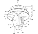
この留め具は、所定部材に形成された取付孔に挿入されて固定されるものである。図1及び図7に示すように、この実施形態における留め具10は、例えば、取付部材5に形成された取付座7に係止されると共に、被取付部材1に形成された円形状の取付孔3に挿入されて固定されるようになっており、取付部材5を被取付部材1に取付けるために用いられるものである。
なお、本発明における「取付孔の裏側」とは、取付孔が形成された部材(ここでは被取付部材1)の厚さ方向の一側部であって、留め具の頭部配置側とは反対側を意味している。
前記被取付部材1としては、例えば、車体パネルや車体フレーム等が挙げられ、前記取付部材5としては、例えば、トリムボード、カバー、ガーニッシュ、アシストグリップ、バンパー、ランプ、インシュレータ(防音材)等が挙げられるが、これらに限定されるものではない。また、取付部材5の取付座7は、その一側部(留め具10の受入れ側)が開口すると共に、底面に係止溝8が形成された枠状をなしており、留め具10の後述の頭部20を保持可能となっている。ただし、例えば、取付部材5に円形状の挿通孔を設けて、その表側に留め具10の頭部20を係合させるようにしてもよく、特に限定はされない。なお、留め具は、上記用途のみならず、取付孔の閉塞用等(いわゆるホールプラグ)として用いてもよく、特に限定はされない。
そして、図1~5に示すように、この留め具10は、被取付部材1の取付孔3の表側に配置される頭部20と、該頭部20に連結されて延出し、取付孔3に挿入係止される脚部30とを有している。
まず、頭部20について説明すると、この実施形態における頭部20は、前記取付部材5の取付座7の係止溝8に挿入される首部21と、該首部21の先端外周から延出した円板状の第1フランジ部23と、前記首部21の軸方向所定位置の外周から延出した薄肉円板状の第2フランジ部25と、同第2フランジ部25の裏面側に連接され、その外周が脚部30側に向けて斜め外方にスカート状に広がる第3フランジ部27とから構成されている。
そして、頭部20の首部21を前記取付座7の係止溝8に挿入し、同取付座7を第1フランジ部23及び第2フランジ部25で挟み込むことで、取付座7に留め具10が装着されるようになっている(図7参照)。なお、頭部の構造は、上記態様に限定されず、所定部材に形成された取付孔の表側周縁に係合する形状であればよい。
一方、図2、図3及び図5に示すように、この実施形態の脚部30は、それぞれの間に間隙35を有して前記頭部20の裏面から延出する複数の軸部31と、各軸部31から脚部30の周方向に延び、取付孔3の裏側周縁に係合する弾性係合片40とを有している。なお、脚部における弾性係合片としては、複数の軸部のうち、少なくとも一対の軸部から、脚部の外径方向及び/又は周方向に延びるものであってもよく(この態様については、後述の第6実施形態で説明する)、特に限定はされない。
図3に示すように、この実施形態における複数の軸部31は、頭部20の第3フランジ部27の、平坦な裏面から延出した一対のものからなり、該一対の軸部31,31の間に、間隙35が設けられている。
図6に示すように、各軸部31は、脚部30を軸方向に直交する断面(以下、「脚部30の横断面」ともいう)で見たときに、各軸部31(複数の軸部31)の内周側(脚部30の内周側)の端部32と、各軸部31(複数の軸部31)の外周側(脚部30の外周側)の端部33とは、脚部30の中心Cを通る直線L上に配置されている。また、図3に示すように、各軸部31の頭部20側の端部は、軸部31の他の部分よりも、やや拡径した拡径部34をなしており、この拡径部34が前記頭部20の第3フランジ部27に連結されている。
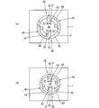
更に図6に示すように、複数の軸部31を分離する間隙35は、脚部30の軸方向に直交する断面において、各軸部31(複数の軸部31)の内周側を共通の円Rで切り欠いた形状をなしており、その結果、各軸部31(複数の軸部31)の内周(ここでは内周側の端部32)が円弧状をなしている。
なお、この実施形態の脚部30においては、一対の軸部31,31を有しているが、例えば、3個や、4個、或いはそれ以上の個数の軸部を有していてもよく(4個の軸部については、後述の実施形態で説明する)、それらの間に間隙を有していればよい。更に各軸部の形状も、断面長板状や断面円形状等としてもよく、特に限定はされない。
また、この実施形態における弾性係合片40は、図6に示すように、脚部30の横断面を見たときに、一対の軸部31,31の外周側の端部33,33から、脚部30の周方向に沿って、外径方向に広がるように湾曲し、各軸部31に対して空隙37を介してそれぞれ延びる一対のものからなり、これらの一対の弾性係合片40,40は、脚部30の中心Cに対して点対称に配置されている。なお、空隙37,37は、一対の軸部31,31の間に設けられた間隙35に連通している(図6参照)。
各弾性係合片40は、脚部30の軸方向における頭部20側の端縁41が、頭部20と離間されている(図3~5参照)。また、各弾性係合片40の、前記端縁41側の外周面には、取付孔3の裏側周縁に係合するように膨出した係合部43が設けられている(図7参照)。更に、各弾性係合片40の、係合部43よりも端縁41側の部分は、取付孔3の内周に挿入される挿入部44をなしている(図7参照)。また、図2~4に示すように、各弾性係合片40の、脚部30の挿入方向側(脚部30の軸方向における頭部20とは反対側)の側面には、脚部30の先端に向かうほど軸部31からの延出長さが短くなるような切込み部46がそれぞれ形成されており、それによって、取付孔3に脚部30を挿入するときに、弾性係合片40を撓みやすくしている。
なお、この実施形態の弾性係合片40は、軸部31から脚部30の周方向及び外径方向に延びる形状をなしているが、弾性係合片としては、軸部から脚部の周方向にのみ延びる形状をなしていてもよく、或いは外径方向にのみ延びる形状をなしていてもよく、取付孔裏側に係合可能な形状であれば特に限定はされない。
また、複数の軸部31は、脚部30の挿入方向先端側が連結部50によって連結されている。図2~5に示すように、この実施形態においては、一対の軸部31,31及び一対の弾性係合片40,40の、脚部30の挿入方向先端側が、連結部50によって互いに連結されている。また、連結部50は、脚部30の挿入方向先端側に向けて次第に縮径する先細形状をなしている。
更に図3及び図5に示すように、連結部50の、脚部30の挿入方向側の外周には、一対の軸部31,31の、脚部30の挿入方向先端部に整合する位置に、肉抜き凹部51,51が形成されている。
そして、本発明の留め具は、複数の軸部31を分離する間隙35が、脚部30の、取付孔3への挿入方向先端部、及び/又は、頭部20を、軸方向に貫通するように形成されている。
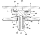
図5に示すように、この実施形態の留め具10においては、一対の軸部31,31を分離する間隙35は、頭部20を軸方向に貫通するように形成されている。すなわち、一対の軸部31,31を分離する間隙35は、頭部20の第3フランジ部27、第2フランジ部25、首部21、第1フランジ部23の中心をそれぞれ貫通して、留め具10の外部に連通した形状をなしている。
なお、上記の間隙は、頭部20側が貫通せず脚部30の取付孔3への挿入方向先端側が貫通していたり、或いは、頭部20及び脚部30の挿入方向先端側の両方が貫通していたりしてもよく、特に限定はされない(これらについては後述の実施形態で説明する)。また、図5に示すように、間隙35の内周面は、脚部30の挿入方向先端側が幅狭で、頭部20の貫通した上端開口に向けて次第に幅広となるテーパ面状をなしている。
以上の留め具10は、例えば、図5及び図6に示すように、頭部20の外周形状や、脚部30の一対の軸部31,31の外周形状、一対の弾性係合片40,40の外周及び内周形状は、脚部30の軸心に対して直交する方向に分割移動する型S1,S2で成形でき、一対の軸部31,31の内周形状や、頭部20の内周形状、間隙35は、脚部30の軸心方向に移動する型S3(図5参照)によって成形できるようになっている。
次に、上記構成からなる留め具10の使用方法及び作用効果について説明する。
まず、留め具10の頭部20の首部21を、取付部材5の取付座7の係止溝8に挿入し(図1参照)、同取付座7を第1フランジ部23及び第2フランジ部25で挟み込むことで、取付座7に留め具10を装着する(図7参照)。
この状態で、被取付部材1の取付孔3に、その表側から留め具10の脚部30を挿入していく。すると、取付孔3の内周に一対の弾性係止片40,40が押圧されて、一対の弾性係合片40,40が脚部内方に向けて撓むと共に、同弾性係合片40を介して一対の軸部31,31も押されて撓みつつ、脚部30が押し込まれていく。このとき、一対の軸部31,31は、その内周側の端部32,32どうしが互いに近接する方向に撓むと共に(図6の矢印F1参照)、脚部30の中心Cを通る直線Lから位置ずれするように、端部32の撓み方向に交差する方向に撓むようになっている(図6の矢印F2参照)。
その後、各弾性係合片40の係合部43が、取付孔3の裏側に抜け出ると、一対の弾性係合片40,40及び一対の軸部31,31が弾性復帰して、係合部43,43が取付孔3の裏側周縁に係合すると共に、頭部20の第3フランジ部27が取付孔3の表側に当接して、取付孔3に留め具10が取付けられて、図7に示すように、留め具10を介して、被取付部材1に取付部材5を取付けることができる。なお、図8(a)に示すように、この状態においては、一対の弾性係合片40,40が撓んで、その挿入部44,44が取付孔3の内周に挿入されると共に、図6に示す状態と比べて一対の軸部31,31が撓み変形した状態で取付孔3内に配置されている。
そして、この留め具10においては、脚部30の一対の軸部31,31を分離する間隙35が、頭部20を軸方向に貫通するように形成されている(図5参照)。そのため、上述したように、取付孔3に脚部30を挿入して、取付孔内周に弾性係合片40が押圧されて撓み変形する際に、弾性係合片40を介して押される軸部31も撓みやすくして、脚部30全体を撓みやすくすることができるので、脚部30の、取付孔3への挿入抵抗を軽減して、挿入性を向上させることができる。
また、図8(b)には、図8(a)に示す取付孔3よりも内径が小さい取付孔3Aであっても、留め具10を取付可能であることが示されている。すなわち、この留め具10においては、複数の軸部31が間隙35により分離されて設けられているので、弾性係合片40だけでなく、軸部31も撓みやすくすることができ、取付孔の内径が、取付孔3から取付孔3Aのように、多少変動しても、図8(b)に示すように、脚部30を挿入係止することができ、取付孔内径に対する留め具10の適用幅を広げることができる。なお、特に図示しないが、取付孔内径が取付孔3よりも多少大きい場合であっても、弾性係合片40の係合部43が取付孔裏側に係合可能な範囲であれば、留め具10を取付けることができる。
また、図6に示すように、この実施形態においては、複数の軸部31を分離する間隙35は、脚部30の軸方向に直交する断面において、共通の円Rで切り欠いた円弧状をなしているので、取付孔3への脚部30の挿入時に、弾性係合片40を介して軸部31に作用する押圧力を、周方向に分散しやすくなり、軸部31の特定箇所への応力集中を緩和して、軸部31の破損を抑制することができる。
更にこの実施形態においては、各軸部31(複数の軸部31)の内周側の端部32と、各軸部31(複数の軸部31)の外周側の端部33とは、脚部30の中心Cを通る直線L上に配置されている(図6参照)。そのため、弾性係合片40の、脚部30の周方向に沿った長さを長く確保することができ(軸部31が脚部中心に対して位置ずれしていると、弾性係合片40の周方向長さを確保しにくい)、取付孔3の裏側周縁への係合面積を広くとれて、取付孔3に対する弾性係合片40の係合力を高めることができる。また、軸部31の、脚部30の径方向側の長さを短くすることができるので、取付孔3への脚部30の挿入時に、軸部31をより撓ませやすくすることができ(長いと剛性が高まり撓ませにくい)、取付孔3に脚部30を挿入しやすくすることができる。
また、図3~5に示すように、この実施形態においては、弾性係合片40の、脚部30の軸方向における頭部20側の端縁41は、頭部20と離間されているので、取付孔3への脚部30の挿入時に、弾性係合片40をより一層撓ませやすくすることができ、取付孔3への脚部30の挿入性を向上させることができる。
更に、図5及び図9に示すように、この実施形態においては、複数の軸部31は、脚部30の挿入方向先端側が連結部50によって連結され、該連結部50の脚部30の挿入方向側の外周には、軸部31の、脚部30の挿入方向先端部に整合する位置に肉抜き凹部51が形成されている。
すなわち、連結部50に凹部51を設けず、肉がある場合は(図9の想像線参照)、弾性係合片40の撓み支点M2は、弾性係合片40の、連結部50との連結部分内側となり、該撓み支点M2と、弾性係合片40の先端との長さ、すなわち、弾性係合片40の撓み長さはD2となる。これに対して、連結部50に凹部51を設けた場合、弾性係合片40の撓み支点M1は、凹部51により肉抜きされた脚部先端側の内側の位置となるため、弾性係合片40の脚部先端側の撓み支点M1と、弾性係合片40の先端との長さ、すなわち、弾性係合片40の撓み長さはD1となる。したがって、連結部50に凹部51を設けた場合には、取付孔3の内周に脚部30を挿入して、取付孔3の内周に押圧される弾性係合片40の撓み長さD1を、凹部なしの場合における弾性係合片40の撓み長さD2に比べて、長く確保することができるので、取付孔3への脚部30の挿入時に弾性係合片40を更に撓ませやすくすることができ、取付孔3に脚部30をより挿入しやすくすることができる。
図10には、本発明の留め具の第2実施形態が示されている。なお、前記実施形態と実質的に同一部分には同符号を付してその説明を省略する。
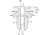
図10に示すように、この実施形態の留め具10Aは、複数の軸部31を分離する間隙35が、脚部30の、取付孔3への挿入方向先端部に設けた連結部50を軸方向に貫通すると共に、頭部20を軸方向に貫通するように形成されている。
この実施形態では、間隙35が、脚部30の取付孔3への挿入方向先端部及び頭部20の両者を軸方向に貫通しているので、取付孔3への脚部30の挿入時に、脚部30全体をより撓みやすくさせることができ、脚部30の取付孔3への挿入抵抗をより軽減することができる。
図11には、本発明の留め具の第3実施形態が示されている。なお、前記実施形態と実質的に同一部分には同符号を付してその説明を省略する。
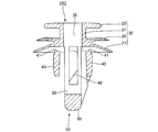
図11に示すように、この実施形態の留め具10Bは、複数の軸部31を分離する間隙35が、脚部30の、取付孔3への挿入方向先端部に設けた連結部50を軸方向に貫通するように形成されている。
この実施形態では、取付孔3への脚部30の挿入時に、最初に挿入される脚部先端側に、間隙35が貫通形成されているので、取付孔3への脚部30の挿入時に、一対の軸部31,31を撓ませやすくすることができ、脚部30の取付孔3への挿入抵抗を軽減することができる。
図12~14には、本発明の留め具の第4実施形態が示されている。なお、前記実施形態と実質的に同一部分には同符号を付してその説明を省略する。
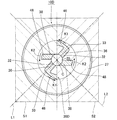
図12~14に示すように、この実施形態の留め具10Cは、脚部30Cの構造が前記実施形態と異なっている。すなわち、この実施形態における脚部30Cは、頭部20の裏面側から延出した4個の軸部31と、各軸部31の外周側の端部33から、周方向及び外径方向にそれぞれ延出した4個の弾性係合片40とを有しており、略羽根車形状をなしている(図14参照)。また、図14に示すように、各軸部31は、脚部30Cを横断面で見たときに、脚部30の周方向に均等な間隔をあけて配置されていると共に、これらの軸部31を分離する間隙35は、各軸部31(複数の軸部31)の内周側を共通の円Rで切り欠いた形状をなし、前記実施形態と同様に、各軸部31(複数の軸部31)の内周側の端部32が円弧状をなしている。更に、図13に示すように、4個の軸部31を分離する間隙35は、頭部20を軸方向に貫通するように形成されている。また、図14に示すように、各軸部31(複数の軸部31)は、脚部30Cを軸方向に直交する断面で見たときに、各軸部31(複数の軸部31)の内周側(脚部30の内周側)の端部32と、各軸部31(複数の軸部31)の外周側(脚部30の外周側)の端部33とは、脚部30Cの中心Cを通る直線L上に配置されている。
この実施形態においても、脚部30Cに設けた4個の軸部31を分離する間隙35が、頭部20を軸方向に貫通するように形成されているので、取付孔3への脚部30Cの挿入時に、弾性係合片40を介して押される各軸部31を撓みやすくして、脚部30C全体を撓みやすくできる。このように、本発明においては、弾性係合片40が複数個存在しても、間隙35によって複数の軸部31を撓みやすくして、脚部30Cの取付孔3への挿入抵抗を軽減でき、挿入性を向上させることができる。
図15~18には、本発明の留め具の第5実施形態が示されている。なお、前記実施形態と実質的に同一部分には同符号を付してその説明を省略する。
図15~18に示すように、この実施形態の留め具10Dは、脚部30Dの構造が前記実施形態と異なっている。すなわち、この実施形態における脚部30Dは、脚部30Dの径方向に対向して配置され、かつ、脚部30Dの周方向に延びる弾性係合片46を有する、一対の第1軸部36,36と、脚部30Dの軸心(図17に示される脚部30Dの中心C)を挟んで、一対の第1軸部36,36とは重ならない位置に配置されると共に、脚部30Dの外径方向に延びる弾性係合片48を有する、少なくとも一対の第2軸部38,38とを有している。
図17に示すように、この実施形態においては、脚部30Dを軸方向に直交する断面(以下、「脚部30Dの横断面」ともいう)で見たときに、一対の第1軸部36,36は、その内周側(脚部30Dの内周側)の端部32と、外周側(脚部30Dの外周側)の端部33とが、脚部30Dの中心Cを通る直線L1上に配置されている。ただし、第2軸部は、少なくとも一対有していればよく、2対以上の第2軸部を有していてよい。
また、図17に示すように、脚部30Dの横断面を見たときに、一対の第1軸部36,36の外周側の端部33,33から、脚部30Dの周方向に沿って湾曲するように、弾性係合片46,46がそれぞれ延びている。これらの弾性係合片46,46は、脚部30Dに対して、同一の延出方向K1で延びており、脚部30Dの中心Cに対して点対称に配置されている。なお、各弾性係合片46は、図6に示す第1実施形態の弾性係合片40よりも、短くなるように延出している(図17参照)。また、図15や図16に示すように、各弾性係合片46は、脚部30Dの軸方向における頭部20側の端縁41が、頭部20と離間しており、かつ、端縁41側の外周面に、取付孔3の裏側周縁に係合する係合部43が設けられている。
一方、図17に示すように、この実施形態における第2軸部38は、脚部30Dの軸心(脚部30Dの中心C)を挟んで、一対の第1軸部36,36とは重ならない位置に配置される、一対のものからなる。また、図17に示すように、各第2軸部38の弾性係合片48は、第1軸部36の弾性係合片46の、脚部30Dに対する延出方向と同じ方向に傾斜して、脚部30Dの外径方向に延びている。
すなわち、図17に示すように、脚部30Dの横断面で見たときに、前記直線L1に対して直交し、かつ、脚部30Dの中心Cを通る直線L2に対して、各第2軸部38の弾性係合片48が、第1軸部36の弾性係合片46の延出方向K1と、同一の傾斜方向K2で傾斜して、脚部30Dの外径方向に延びている。なお、各第2軸部38も、第1軸部36の弾性係合片46の、脚部30Dに対する延出方向K1と同じ方向に傾斜して、脚部30Dの外径方向に延びている(図17参照)。また、一対の第2軸部38,38及びそれらの弾性係合片48,48は、図17に示すように、脚部30Dの横断面で見たときに、脚部30Dの中心Cに対して点対称に配置され、かつ、互いに平行となるように配置されている。更に、図15や図18に示すように、第1軸部36及び第2軸部38は、頭部20に連結された構造となっている。
また、図15や図16に示すように、各弾性係合片48は、脚部30Dの挿入方向先端側の外面がテーパ面状をなしていると共に、頭部20側の基端部が頭部20に離間して、取付孔3の裏側周縁に係合するテーパ面状の係合部43をなしており、第2軸部38から脚部30Dの外径方向に向けてそれぞれ延出した形状をなしている。更に図16に示すように、各弾性係合片48の係合部43は、前記第1軸部36の弾性係合片46の係合部43とほぼ整合する位置に配置されている。
そして、この実施形態の留め具10Dにおいては、図18に示すように、一対の第1軸部36,36、及び、一対の第2軸部38,38を分離する間隙35が、脚部30Dの、取付孔3への挿入方向先端部を軸方向に貫通するように形成されている。また、図15や図16に示すように、各第1軸部36及びその弾性係合片46の、脚部30Dの挿入方向先端側と、各第2軸部38及びその弾性係合片48の、脚部30Dの挿入方向先端側とが、環状をなした連結部50Dによって互いに連結されている。なお、この連結部50Dは前記間隙35に連通し、かつ、その外面が、脚部30Dの挿入方向先端側に向けて次第に縮径するテーパ面状をなしている。
そして、上記構成からなる留め具10Dにおいては、脚部30Dは、一対の第1軸部36,36と、一対の第2軸部38,38とを有しているので、その断面積を増大させることができる。その結果、図18に示すように、取付孔3に脚部30Dが挿入され、各第1軸部36の弾性係合片46の係合部43や、各第2軸部38の弾性係合片48の係合部43が、取付孔3の裏側周縁に係合した状態で、脚部30Dに剪断力F3(取付孔3の中心に対して直交する横向きの力)が作用しても、該剪断力F3に対する強度を高めることができる。また、一対の第1軸部36,36の弾性係合片46,46、及び、一対の第2軸部38,38の弾性係合片48,48が、取付孔3の裏側周縁にそれぞれ係合するので、取付孔3の裏側周縁に対する係合箇所を増やして、取付孔3に対する留め具10Dの保持力を高めることができる。
更にこの実施形態においては、図17に示すように、各第2軸部38の弾性係合片48は、第1軸部36の弾性係合片46の、脚部30Dに対する延出方向K1と同じ方向(矢印K2参照)に傾斜して、脚部30Dの外径方向に延びているので、各第1軸部36の弾性係合片46と、各第2軸部38の弾性係合片48とを、取付孔3に対して、その周方向に略均等に配置することができ、複数の弾性係合片46,48を、取付孔3の裏側周縁にバランスよく係合させることができる。
ところで、上記構造をなした留め具10Dは、例えば、図17に示すように、脚部30Dの各第1軸部36や各第2軸部38の外周形状や、それらの弾性係合片46,48の外周や内周の形状は、脚部30Dの軸心に対して直交する方向に分割移動する型S1,S2で成形される。このとき、この実施形態においては、各第2軸部38の弾性係合片48は、第1軸部36の弾性係合片46の、脚部30Dに対する延出方向K1と同じ方向(矢印K2参照)に傾斜して、脚部30Dの外径方向に延びているので、留め具10Dを成形した後、該留め具10Dの成形品から前記型S1,S2を型抜きするときに、これらの型S1,S2の型抜き方向に対して、成形品が引っ掛かる部分を少なくすることができる。その結果、成形後の脚部30Dから、型S1,S2を型抜きしやすくすることができ、留め具10Dの製造コストを低減することができる。
図19~22には、本発明の留め具の第6実施形態が示されている。なお、前記実施形態と実質的に同一部分には同符号を付してその説明を省略する。
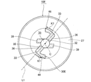
図19~22に示すように、この実施形態の留め具10Eは、脚部30Eの構造が前記実施形態と異なっている。すなわち、この実施形態における脚部30Eは、脚部30Eの径方向に対向して配置され、かつ、脚部30Eの周方向に延びる弾性係合片46を有する、一対の第1軸部36,36と、脚部30Eの軸心(図21に示される脚部30Eの中心C)を挟んで、一対の第1軸部36,36とは重ならない位置に配置されると共に、前記弾性係合片を有しない、少なくとも一対の第3軸部39,39とを有している。
図21に示すように、この実施形態においては、脚部30Eを軸方向に直交する断面(以下、「脚部30Eの横断面」ともいう)で見たときに、一対の第1軸部36,36は、その内周側の端部32と、外周側の端部33とが、脚部30Dの中心Cを通る直線L1上に配置されると共に、脚部30Eの軸心(脚部30Eの中心C)を挟んで、一対の第1軸部36,36とは重ならない位置に配置される一対の第2軸部39,39が、隣接する各第1軸部36に対して近接する方向に傾き、かつ、互いに平行となるように配置されている。そして、図19や図20に示すように、各第2軸部39には、第5実施形態における第2軸部38の弾性係合片48のような、弾性係合片を有しない構造となっている。なお、上記の第2軸部は、少なくとも一対有していればよく、2対以上の第2軸部を有していてよい。また、この実施形態の留め具10Eにおいては、図22に示すように、一対の第1軸部36,36、及び、一対の第2軸部39,39を分離する間隙35が、脚部30Eの、取付孔3への挿入方向先端部を軸方向に貫通するように形成されている。
また、各第3軸部39は、第1軸部36の弾性係合片46の、脚部30Eに対する延出方向K1と同じ方向に傾斜して、脚部30Dの外径方向に延びている(図21参照)。更に図19や図22に示すように、第1軸部36及び第3軸部39は、頭部20に連結された構造となっている。
上記構造をなした留め具10Eにおいては、脚部30Eの軸心を挟んで、一対の第1軸部36,36とは重ならない位置に配置されると共に、弾性係合片を有しない、少なくとも一対の第3軸部39,39は、取付孔3に脚部30Eを挿入する際に、撓ませる必要がないので、各第3軸部39の断面積を増やすことができる。その結果、図22に示すように、取付孔3に脚部30Eが挿入され、各第1軸部36の弾性係合片46の係合部43が取付孔3の裏側周縁に係合した状態で、脚部30Eに剪断力F3が作用した場合に、その剪断力F3に対する強度を、より高めることができる。また、第3軸部39は弾性係合片を有しないので、取付孔3への脚部30Eの挿入時に、該取付孔3の内周に弾性係合片が当接することがなく、脚部30Eの、取付孔3に対する挿入抵抗を低くすることができ、その挿入性を向上させることができる。
なお、本発明は、上述した実施形態に限定されるものではなく、本発明の要旨の範囲内で、各種の変形実施形態が可能であり、そのような実施形態も本発明の範囲に含まれる。
1 被取付部材
3,3A 取付孔
5 取付部材
10,10A,10B,10C,10D,10E 留め具
20 頭部
30,30C,30D,30E 脚部
31 軸部
32 内周側の端部
33 外周側の端部
35 間隙
36 第1軸部
38 第2軸部
39 第3軸部
40,46,48 弾性係合片
41 端縁
43 係合部
50 連結部
51 凹部
3,3A 取付孔
5 取付部材
10,10A,10B,10C,10D,10E 留め具
20 頭部
30,30C,30D,30E 脚部
31 軸部
32 内周側の端部
33 外周側の端部
35 間隙
36 第1軸部
38 第2軸部
39 第3軸部
40,46,48 弾性係合片
41 端縁
43 係合部
50 連結部
51 凹部
Claims (9)
- 取付孔に挿入されて取付けられる留め具であって、
前記取付孔の表側に配置される頭部と、該頭部に連結されて延出し、前記取付孔に挿入係止される脚部とを有し、
前記脚部は、それぞれの間に間隙を有して前記頭部の裏面から延出する複数の軸部と、該複数の軸部のうち、少なくとも一対の軸部から前記脚部の外径方向及び/又は周方向に延び、前記取付孔の裏側周縁に係合する弾性係合片とを有しており、
前記複数の軸部を分離する間隙は、前記脚部の、前記取付孔への挿入方向先端部、及び/又は、前記頭部を、軸方向に貫通するように形成されていることを特徴とする留め具。 - 前記弾性係合片は、前記複数の軸部の、各軸部から延びている請求項1記載の留め具。
- 前記複数の軸部を分離する間隙は、前記脚部の軸方向に直交する断面において、前記複数の軸部の内周側を共通の円で切り欠いた形状をなし、前記複数の軸部の内周が円弧状をなしている請求項1又は2記載の留め具。
- 前記複数の軸部の内周側の端部と、前記複数の軸部の外周側の端部とは、前記脚部の中心を通る直線上に配置されている請求項1~3のいずれか1つに記載の留め具。
- 前記弾性係合片の、前記脚部の軸方向における前記頭部側の端縁は、前記頭部と離間されている請求項1~4のいずれか1つに記載の留め具。
- 前記複数の軸部は、前記脚部の挿入方向先端側が連結部によって連結されており、
該連結部の外周には、前記軸部の、前記脚部の挿入方向先端部に整合する位置に肉抜き凹部が形成されている請求項1~5のいずれか1つに記載の留め具。 - 前記脚部は、前記脚部の径方向に対向して配置され、かつ、前記脚部の周方向に延びる前記弾性係合片を有する、一対の第1軸部と、
前記脚部の軸心を挟んで、前記一対の第1軸部とは重ならない位置に配置されると共に、前記脚部の外径方向に延びる前記弾性係合片を有する、少なくとも一対の第2軸部とを有している、請求項1及び3~6のいずれか1つに記載の留め具。 - 前記少なくとも一対の第2軸部の前記弾性係合片は、前記一対の第1軸部の前記弾性係合片の、前記脚部に対する延出方向と同じ方向に傾斜して、前記脚部の外径方向に延びている請求項7記載の留め具。
- 前記脚部は、前記脚部の径方向に対向して配置され、かつ、前記脚部の周方向に延びる前記弾性係合片を有する、一対の第1軸部と、
前記脚部の軸心を挟んで、前記一対の第1軸部とは重ならない位置に配置されると共に、前記弾性係合片を有しない、少なくとも一対の第3軸部とを有している、請求項1及び3~6のいずれか1つに記載の留め具。
Priority Applications (1)
| Application Number | Priority Date | Filing Date | Title |
|---|---|---|---|
| JP2018516379A JP6569925B2 (ja) | 2016-05-11 | 2017-03-28 | 留め具 |
Applications Claiming Priority (2)
| Application Number | Priority Date | Filing Date | Title |
|---|---|---|---|
| JP2016-095607 | 2016-05-11 | ||
| JP2016095607 | 2016-05-11 |
Publications (1)
| Publication Number | Publication Date |
|---|---|
| WO2017195485A1 true WO2017195485A1 (ja) | 2017-11-16 |
Family
ID=60268007
Family Applications (1)
| Application Number | Title | Priority Date | Filing Date |
|---|---|---|---|
| PCT/JP2017/012729 Ceased WO2017195485A1 (ja) | 2016-05-11 | 2017-03-28 | 留め具 |
Country Status (2)
| Country | Link |
|---|---|
| JP (1) | JP6569925B2 (ja) |
| WO (1) | WO2017195485A1 (ja) |
Citations (6)
| Publication number | Priority date | Publication date | Assignee | Title |
|---|---|---|---|---|
| JP2003056532A (ja) * | 2001-06-05 | 2003-02-26 | Yazaki Corp | クランプ |
| JP2008519946A (ja) * | 2004-11-12 | 2008-06-12 | アー ライモント エ カンパニュイ | 固定装置 |
| JP2009281581A (ja) * | 2008-04-25 | 2009-12-03 | Piolax Inc | クリップ |
| WO2014119209A1 (ja) * | 2013-02-04 | 2014-08-07 | 株式会社パイオラックス | クリップ及びガラス仮固定方法 |
| JP2015001236A (ja) * | 2013-06-13 | 2015-01-05 | 株式会社パイオラックス | クリップ |
| JP2015072021A (ja) * | 2013-10-01 | 2015-04-16 | 株式会社パイオラックス | 取付孔への係止具 |
-
2017
- 2017-03-28 JP JP2018516379A patent/JP6569925B2/ja active Active
- 2017-03-28 WO PCT/JP2017/012729 patent/WO2017195485A1/ja not_active Ceased
Patent Citations (6)
| Publication number | Priority date | Publication date | Assignee | Title |
|---|---|---|---|---|
| JP2003056532A (ja) * | 2001-06-05 | 2003-02-26 | Yazaki Corp | クランプ |
| JP2008519946A (ja) * | 2004-11-12 | 2008-06-12 | アー ライモント エ カンパニュイ | 固定装置 |
| JP2009281581A (ja) * | 2008-04-25 | 2009-12-03 | Piolax Inc | クリップ |
| WO2014119209A1 (ja) * | 2013-02-04 | 2014-08-07 | 株式会社パイオラックス | クリップ及びガラス仮固定方法 |
| JP2015001236A (ja) * | 2013-06-13 | 2015-01-05 | 株式会社パイオラックス | クリップ |
| JP2015072021A (ja) * | 2013-10-01 | 2015-04-16 | 株式会社パイオラックス | 取付孔への係止具 |
Also Published As
| Publication number | Publication date |
|---|---|
| JP6569925B2 (ja) | 2019-09-04 |
| JPWO2017195485A1 (ja) | 2019-02-21 |
Similar Documents
| Publication | Publication Date | Title |
|---|---|---|
| JP4649120B2 (ja) | クリップ | |
| US8496420B2 (en) | Clip | |
| US8333540B2 (en) | Clip | |
| EP1375931A1 (en) | Two-piece clip | |
| CN101421060B (zh) | 构件彼此的接合方法 | |
| US20140208561A1 (en) | Elastic alignment assembly for aligning mated components and method of reducing postional variation | |
| JP6255033B2 (ja) | 止め具 | |
| JP2014029210A (ja) | 可変グリップ式ブラインドリベット | |
| CN105339685A (zh) | 推入式紧固件 | |
| CN102612616B (zh) | 汽车用的闭塞栓 | |
| JP3198349U (ja) | エアレスタイヤとホイールの結合構造とそのファスナー | |
| JP6096791B2 (ja) | パネルを締結するリベット機構 | |
| JP6435231B2 (ja) | 留め具 | |
| JP2008002644A (ja) | ディスクブレーキ用パッドクリップ | |
| WO2014088043A1 (ja) | ホールプラグ | |
| JP6569925B2 (ja) | 留め具 | |
| CN111512076B (zh) | 孔塞 | |
| JP2019052673A (ja) | クリップ | |
| US9705227B2 (en) | Plug contact element having a fold-over layer | |
| JP4712672B2 (ja) | クリップ | |
| WO2012157614A1 (ja) | ホールプラグ | |
| JP3863812B2 (ja) | クリップ | |
| JP5886066B2 (ja) | クリップ | |
| JP7850589B2 (ja) | 留め具 | |
| JP6976829B2 (ja) | プラスチックファスナー |
Legal Events
| Date | Code | Title | Description |
|---|---|---|---|
| DPE1 | Request for preliminary examination filed after expiration of 19th month from priority date (pct application filed from 20040101) | ||
| ENP | Entry into the national phase |
Ref document number: 2018516379 Country of ref document: JP Kind code of ref document: A |
|
| NENP | Non-entry into the national phase |
Ref country code: DE |
|
| 121 | Ep: the epo has been informed by wipo that ep was designated in this application |
Ref document number: 17795846 Country of ref document: EP Kind code of ref document: A1 |
|
| 122 | Ep: pct application non-entry in european phase |
Ref document number: 17795846 Country of ref document: EP Kind code of ref document: A1 |