WO2017193791A1 - 带斜扁支脚的防霜机立柱固定支座 - Google Patents
带斜扁支脚的防霜机立柱固定支座 Download PDFInfo
- Publication number
- WO2017193791A1 WO2017193791A1 PCT/CN2017/081390 CN2017081390W WO2017193791A1 WO 2017193791 A1 WO2017193791 A1 WO 2017193791A1 CN 2017081390 W CN2017081390 W CN 2017081390W WO 2017193791 A1 WO2017193791 A1 WO 2017193791A1
- Authority
- WO
- WIPO (PCT)
- Prior art keywords
- frost
- base
- flat
- pedestal
- base plate
- Prior art date
- Legal status (The legal status is an assumption and is not a legal conclusion. Google has not performed a legal analysis and makes no representation as to the accuracy of the status listed.)
- Ceased
Links
Images




Classifications
-
- A—HUMAN NECESSITIES
- A01—AGRICULTURE; FORESTRY; ANIMAL HUSBANDRY; HUNTING; TRAPPING; FISHING
- A01G—HORTICULTURE; CULTIVATION OF VEGETABLES, FLOWERS, RICE, FRUIT, VINES, HOPS OR SEAWEED; FORESTRY; WATERING
- A01G13/00—Protection of plants
-
- A—HUMAN NECESSITIES
- A01—AGRICULTURE; FORESTRY; ANIMAL HUSBANDRY; HUNTING; TRAPPING; FISHING
- A01G—HORTICULTURE; CULTIVATION OF VEGETABLES, FLOWERS, RICE, FRUIT, VINES, HOPS OR SEAWEED; FORESTRY; WATERING
- A01G13/00—Protection of plants
- A01G13/06—Devices for generating heat, smoke or fog in gardens, orchards or forests, e.g. to prevent damage by frost
-
- A—HUMAN NECESSITIES
- A01—AGRICULTURE; FORESTRY; ANIMAL HUSBANDRY; HUNTING; TRAPPING; FISHING
- A01G—HORTICULTURE; CULTIVATION OF VEGETABLES, FLOWERS, RICE, FRUIT, VINES, HOPS OR SEAWEED; FORESTRY; WATERING
- A01G13/00—Protection of plants
- A01G13/08—Mechanical apparatus for circulating the air
-
- E—FIXED CONSTRUCTIONS
- E04—BUILDING
- E04H—BUILDINGS OR LIKE STRUCTURES FOR PARTICULAR PURPOSES; SWIMMING OR SPLASH BATHS OR POOLS; MASTS; FENCING; TENTS OR CANOPIES, IN GENERAL
- E04H12/00—Towers; Masts or poles; Chimney stacks; Water-towers; Methods of erecting such structures
- E04H12/22—Sockets or holders for poles or posts
- E04H12/2207—Sockets or holders for poles or posts not used
- E04H12/2215—Sockets or holders for poles or posts not used driven into the ground
-
- F—MECHANICAL ENGINEERING; LIGHTING; HEATING; WEAPONS; BLASTING
- F16—ENGINEERING ELEMENTS AND UNITS; GENERAL MEASURES FOR PRODUCING AND MAINTAINING EFFECTIVE FUNCTIONING OF MACHINES OR INSTALLATIONS; THERMAL INSULATION IN GENERAL
- F16M—FRAMES, CASINGS OR BEDS OF ENGINES, MACHINES OR APPARATUS, NOT SPECIFIC TO ENGINES, MACHINES OR APPARATUS PROVIDED FOR ELSEWHERE; STANDS; SUPPORTS
- F16M11/00—Stands or trestles as supports for apparatus or articles placed thereon ; Stands for scientific apparatus such as gravitational force meters
- F16M11/20—Undercarriages with or without wheels
- F16M11/22—Undercarriages with or without wheels with approximately constant height, e.g. with constant length of column or of legs
Definitions
- the invention relates to a frost-proof machine column fixing device, in particular to a fixing device and a method for a tea (fruit) garden frost-proof machine column, belonging to the technical field of agricultural machinery.
- the conventional fixing method of the column of the existing anti-frosting machine (1) manually digging a pit of a certain depth in the position where the anti-frosting machine is installed, pouring concrete in the pit, and placing the anchor bolt on the upper end of the concrete, passing the anchor bolt Fix the lower flange of the column to the concrete foundation.
- the disadvantage of this method is that the labor intensity is large, and the installation efficiency of the anti-frost column is low.
- (2) Use the tool to dig a pit with a certain depth and a diameter slightly larger than the diameter of the column at the installation position of the frost-proof machine. Place the column in the pit, keep the column vertical, adjust the direction and fill it with soil or concrete.
- the disadvantage of this method is that in order to ensure the working requirements of the column, the diameter of the pit can only be slightly larger than the diameter of the column. It is difficult to completely eliminate the gap between the soil and the column due to the late landfill work, the vibration during the use of the frost guard and The effect of the wind and the like will further increase the gap, and seriously reduce the safety performance and work efficiency of the frost preventer.
- the invention solves the above problems by driving the base plate into the soil, which greatly reduces the labor intensity and improves the installation efficiency of the frost preventer. .
- China's utility model patent CN201120394200.1 discloses a fixing device for the column of the plant anti-frosting machine, which adopts several root frame mechanisms at the lower end of the column, and the frame mechanism includes the lateral bending of the steel plate beam into a trough type.
- the root frame beam and the U-shaped hoop have a pair of positioning rods in the middle of the root frame beam, and the lower part of the column is positioned between a stack of positioning rods, and is vertically fixedly connected with the root frame beam through the U-shaped hoop. This method requires excavating larger and deeper pits, increasing labor intensity and low installation efficiency.
- the present invention has proposed a method for avoiding digging deep pits and improving the fixing stability of the device in view of its shortcomings.
- the common feature of the above method is that it is necessary to dig a small pit with small diameter and high precision in the installation position of the frost guard, which is labor intensive and time-consuming and laborious.
- the invention avoids the work of digging deep pits, and uses the base to be driven into The soil method reduces labor intensity and improves the installation efficiency of the frost guard column.
- the height of the anti-frost machine from the ground needs to reach 6.7m. Since the standard length of the pipe is 6m, the conventional anti-frost pipe column is made of non-standard pipe, which is very expensive.
- the invention adopts the joint support, so that the frostproof machine column can adopt the standard pipe, which can save the cost by 50%.
- the object of the present invention is to provide a frost-proofing machine column fixing support with inclined flat feet suitable for use in multi-stone land, simple structure and convenient installation, so as to reduce labor intensity during installation, reduce installation time, and effectively prevent Frost machine column Rotating and tilting reduces manufacturing and installation costs, increases economic efficiency, and facilitates transportation and storage.
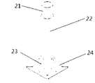
- the coupling support 2 includes a tilt prevention guide cylinder 21, a fixed pillar 22, a rib 23 and a coupling plate 24.
- the outer diameter of the anti-tilt guide cylinder 21 is smaller than the inner diameter of the fixed pillar 22 and the inner diameter of the frost guard column 11 by 0.5 to 1 mm.
- the two ends are chamfered to facilitate the installation of the anti-rolling guide cylinder 21 and the frost guard 1;
- the frost guard is installed at the upper end of the coupling support 2, and the lower end of the frost guard column 11 is provided with a small hole for coupling
- the anti-roll guide cylinder 21 of the support 2 is plug welded;
- the anti-roll guide cylinder 21 is installed in the fixed post 22 and the frost guard column 11 with a length greater than 200 mm, and is fixed by plug welding to enhance its anti-dumping ability;
- the outer diameter of the anti-fresh column 11 is equal to the outer diameter of the frost-proof column 11,
- the upper end of the fixing post 22 is provided with a small hole for plug welding
- the outer end of the connecting plate 24 is provided with four bases for connecting the coupling base 2 and the base 4.
- the anti-tilt guide cylinder 21 is first placed at about 200 mm of the upper end of the fixed strut 22, and the anti-tilt guide cylinder 21 and the fixed strut 22 are fixed by means of plug welding, and the fixed strut 22 is vertically welded to the center of the joint plate 24, and the rib is welded.
- the plate 23 is welded between the fixed strut 22 and the coupling plate 24 for enhancing the anti-torsion capability of the anti-frosting machine.
- the base 4 is composed of a base plate 41, a flat leg 42 and the like.
- the inner side of the base plate has an upper hole 43 and a lower hole 44, and an upper end thereof has a hole for mounting the base bolt 3.
- each base plate 41 is sequentially circulated into the soil by 20-30 mm, and is connected when the upper end of the lower hole 44 is close to the ground.
- the loops are snapped into the lower holes 44 of the base plates 41 to fix the base plates 41, and continue to be beaten until the upper holes 43 are close to the ground, and the connecting rings are caught in the upper holes 43 of the base plates 41, and then the flat legs are 42 is driven into the soil from the flat hole at the outer edge of the base plate, and the installation of the flat legs 42 is performed by symmetrical mounting.
- the two flat legs 42 are respectively placed along the outer edge of the same base plate 41 in the opposite direction.
- the soil on both sides of the base plate 41 is driven until the two holes at the upper end of the flat leg 42 are respectively located on both sides of the base plate 41, the bolt is inserted into the two holes of the flat leg 42 and the nut is screwed, and then the base is in a symmetrical position.
- the flat legs 42 are mounted on the plate 41 in the same manner; after the base 4 is installed, the base support 3 is used to fix the joint support 2 to the base 4 in a symmetrical manner; after the base bolt 4 is installed, the soil is used.
- the lands 24 are filled in, which is both safe and beautiful.
- the frost guard column 11 is placed on the anti-roll guide cylinder 21, and the anti-roll guide cylinder 21 and the frost guard column 11 are fixed by plug welding.
- the cross-sectional shape of the fixing member is preferably a cross flower shape.
- the number of the susceptor bolts 4 is preferably four.
- the number of the flat legs 42 is preferably eight.
- the upper hole 43 and the lower hole 44 are preferably rectangular holes.
- the fixing manner between the anti-tilt guide cylinder 21 and the fixed stay 22, the anti-roll guide cylinder 21 and the frost guard column 11 is preferably plug welding.
- the invention has the advantages of simple structure and convenient installation, not only reduces the labor intensity during installation, but also improves the horizontal torsion and anti-dumping ability of the anti-frosting machine column, increases the working reliability of the anti-frosting machine, and can be applied to the multi-stone land;
- the use of the invention relates to the use of the joint support, so that the standard pipe can replace the non-standard pipe which was originally selected to meet the height of the frost-proof machine, which saves the cost by 50%, is convenient for transportation and storage, and reduces the installation of the frost-proof machine. Manufacturing costs increase the installation efficiency and economic benefits of the frost-proof machine.
- Figure 1 is a schematic view showing the overall structure of the anti-frosting machine of the present invention
- FIG. 2 is a schematic structural view of a frost guard of the present invention
- Figure 3 is a schematic view of the mounting structure of the coupling support and the base
- Figure 4 is a schematic view showing the structure of the coupling support of the present invention
- Figure 5 is a schematic view showing the mounting structure of the base plate of the present invention.
- Figure 6 is a schematic structural view of a base plate of the present invention
- Figure 7 is a schematic view showing the structure of the flat leg of the present invention.
- Figure 8 is a schematic view of the base bolt of the present invention
- 1 anti-frost machine 11 anti-frost machine column, 12 anti-frost blade, 13 anti-frost motor, 14 anti-frost machine connecting parts, 2 joint support, 21 anti-roll guide tube, 22 fixed pillar, 23 ribs Plate, 24 gusset, 3 pedestal bolt, 4 pedestal, 41 base plate, 42 flat feet, 43 upper holes, 44 lower holes
- the invention is composed of an anti-frosting machine 1, a coupling support 2 and a base 4, and the combined installation method achieves the height requirement and reliability requirement of the anti-frost operation.
- the anti-frosting machine 1 is sleeved on the anti-rolling guide cylinder 21 of the coupling support 2 through the anti-frosting machine column 11, and the frost-proofing machine 1 and the coupling support 2 are fixed by the plug welding; between the coupling support 2 and the base 4 It is fixed by the base bolt 3.
- the frost guard is composed of a frost guard column 11, an anti-frost blade 12, an anti-fryer motor 13, and an anti-frost connecting member 14.
- the frost guard column 11 is a standard pipe having a length of 6 m.
- the coupling support 2 is fixed by the anti-roll guide cylinder 21, the fixed stay 22, the rib 23, and the coupling plate 24.
- the outer diameter of the anti-tilt guide cylinder 21 is smaller than the inner diameter of the fixed strut 22 by 0.5-1 mm, and the upper end of the fixed strut 22 is opened with two or three sets of small holes.
- the anti-tilt guide cylinder 21 is inserted into the upper end of the fixed strut 22 by about 200 mm, and the plug is used.
- the welding method fixes the anti-tilt guide cylinder 21 and the fixed strut 22; then the fixed strut 22 is vertically welded to the center of the coupling plate 24, and then the rib 23 is welded between the fixed strut 22 and the coupling plate 24 to reinforce the fixed strut 22 Anti-dumping performance.
- the base 4 is fixed by a base plate 41, a flat leg 42 and the like.
- the base plate 41 is a wedge-shaped steel plate having a hole at the upper end, the inner side and the outer edge, and the upper end hole is used for the base bolt.
- the inner upper hole 43, the lower hole 44 is used for the connection of the connecting ring, the outer edge of the hole is used for the mounting of the flat leg;
- the flat leg 42 has two holes at the double end for mounting the bolt to The flat legs 42 are fixed to the base plate 41.
- the frost-proof machine column fixing support of the invention overcomes the high precision of the excavation aperture precision, the small-diameter deep hole and the backfill compaction thereof by the pedestal being driven into the soil. Difficulties, reduced labor intensity, and improved installation efficiency; the use of joint bearings enables standard pipes to replace the non-standard pipes that were originally selected to meet the height of the frost-proof machine, which greatly saves material costs and facilitates transportation and storage.
- the opening on the base plate connects the soil inside and outside the pedestal into a whole, which enhances the stability of the pedestal and reduces the damage to the soil.
- the present invention is a device that can be used for fixing a post of a frost guard.
- the two flat legs 42 are firstly driven into the soil on both sides of the base plate 41 along the opposite holes on the outer edge of the same base plate 41 until the upper ends of the flat legs 42 are respectively located on the base plate 41.
- insert the bolt into the two holes of the flat leg 42 and screw the nut then install the flat leg 42 in the same way on the base plate 41 in the symmetrical position; after the base 4 is installed, use the base bolt 3
- the joint support 2 is fixed on the base 4; subsequently, the joint plate 24 is filled with soil to make the land flat
- the frost guard column 11 is placed on the anti-roll guide tube 21, and the anti-roll guide tube 21 and the frost guard column 11 are fixed by plug welding.
- the inner diameter of the anti-frosting machine column 11 is different from the inner diameter of the anti-rolling guide cylinder 21 by 0.5-1 mm to enhance its bending resistance, anti-dumping, horizontal torsion resistance and vibration reduction, the outer diameter of the frost guard column 11 and the outer diameter of the fixed strut 22 Equal to achieve a visual aesthetic effect.
Landscapes
- Life Sciences & Earth Sciences (AREA)
- Engineering & Computer Science (AREA)
- Environmental Sciences (AREA)
- General Health & Medical Sciences (AREA)
- Toxicology (AREA)
- Health & Medical Sciences (AREA)
- General Engineering & Computer Science (AREA)
- Mechanical Engineering (AREA)
- Forests & Forestry (AREA)
- Architecture (AREA)
- Civil Engineering (AREA)
- Structural Engineering (AREA)
- Foundations (AREA)
- Catching Or Destruction (AREA)
Abstract
Description
Claims (7)
- 带斜扁支脚的防霜机立柱固定支座,包括防霜机(1),联接支座(2),基座螺栓(3),基座(4)。其特征在于,所述联接支座(2)由防倾导向筒(21)、固定支柱(22)、筋板(23)和联接板(24)固定而成;所述基座(4)由基座板(41)、扁支脚(42)等组成;其特征还在于,所述基座螺栓(3)用于联接支座(2)与基座(4)的固接。
- 根据权利要求1所述的带斜扁支脚的防霜机立柱固定支座,其特征在于,所述防倾导向筒(21)的外径比固定支柱(22)的内径及防霜机立柱(11)的内径小0.5-1mm,并且防霜机立柱(11)的外径与固定支柱(22)的外径相等,不仅使防霜机立柱固定装置易于加工和安装,且使外观漂亮,还能有效保证三者联接的可靠性。
- 根据权利要求1所述的带斜扁支脚的防霜机立柱固定支座,其特征在于,所述防倾导向筒(21)两端设有倒角,以利于防倾导向筒(21)和防霜机(1)的安装;防倾导向筒(21)装入固定支柱(22)和防霜机立柱(11)中的长度大于200mm,并使用塞焊固定,塞焊孔为2组或3组,以增强其抗倾倒能力,同时增强外观的美感。
- 根据权利要求1所述的带斜扁支脚的防霜机立柱固定支座,其特征在于,所述基座板(31)上开设有孔,基座内外的土壤通过开孔结成一整体,能提高基座(3)的稳固可靠性。
- 根据权利要求1所述的带斜扁支脚的防霜机立柱固定支座,其特征在于,所述基座(4)的横截面形状为十字花形、Y型等多种形状。
- 根据权利要求4所述的带斜扁支脚的防霜机立柱固定支座,其特征在于,所述基座板(41)上有不同作用的孔,用于安装连接环、扁支脚(42)、基座螺栓(3)等零部件。
- 根据权利要求5所述的带斜扁支脚的防霜机立柱固定支座,其特征在于,所述扁支脚(42)上端开有两孔,当基座板(41)外边缘的孔接近地面时将两扁支脚(42)沿相反方向的孔打入土壤之中直至扁支脚(42)上端两孔位于基座板(41)两侧,随后在扁支脚(42)上端两孔中安装好螺栓将扁支脚(42)与基座板(41)固定,在安装好一块基座板(41)上的扁支脚(42)后应该安装相对称基座板(41)上的扁支脚(42)。
Priority Applications (2)
| Application Number | Priority Date | Filing Date | Title |
|---|---|---|---|
| US16/079,092 US10785924B2 (en) | 2016-05-09 | 2017-04-21 | Defrosting machine column fixed support with inclined flat leg |
| GB1819962.0A GB2566195B (en) | 2016-05-09 | 2017-04-21 | Defrosting machine column fixed support with inclined flat leg |
Applications Claiming Priority (2)
| Application Number | Priority Date | Filing Date | Title |
|---|---|---|---|
| CN201610300440.8A CN105941024B (zh) | 2016-05-09 | 2016-05-09 | 带斜扁支脚的防霜机立柱固定支座 |
| CN201610300440.8 | 2016-05-09 |
Publications (1)
| Publication Number | Publication Date |
|---|---|
| WO2017193791A1 true WO2017193791A1 (zh) | 2017-11-16 |
Family
ID=56914528
Family Applications (1)
| Application Number | Title | Priority Date | Filing Date |
|---|---|---|---|
| PCT/CN2017/081390 Ceased WO2017193791A1 (zh) | 2016-05-09 | 2017-04-21 | 带斜扁支脚的防霜机立柱固定支座 |
Country Status (4)
| Country | Link |
|---|---|
| US (1) | US10785924B2 (zh) |
| CN (1) | CN105941024B (zh) |
| GB (1) | GB2566195B (zh) |
| WO (1) | WO2017193791A1 (zh) |
Families Citing this family (2)
| Publication number | Priority date | Publication date | Assignee | Title |
|---|---|---|---|---|
| CN105941024B (zh) * | 2016-05-09 | 2019-03-29 | 江苏大学 | 带斜扁支脚的防霜机立柱固定支座 |
| DE102020128325A1 (de) * | 2020-10-28 | 2022-04-28 | Rwe Renewables Gmbh | Windkraftanlagengründungsstruktur |
Citations (6)
| Publication number | Priority date | Publication date | Assignee | Title |
|---|---|---|---|---|
| JPH08242707A (ja) * | 1995-03-06 | 1996-09-24 | Yamamoto Mfg Co Ltd | 霜害防止装置 |
| US20120079779A1 (en) * | 2010-10-01 | 2012-04-05 | Laser Perfect Products Company, Inc. | Anchor system for fencing |
| CN202282965U (zh) * | 2011-10-17 | 2012-06-27 | 中外合资镇江古田农业环境工程有限公司 | 植物防霜机立柱固定装置 |
| DE102012200860A1 (de) * | 2012-01-20 | 2013-07-25 | Georg Becker | Freilandgebläse |
| CN204409131U (zh) * | 2015-01-05 | 2015-06-24 | 黑龙江职业学院 | 果树结果期防断枝撑架 |
| CN105941024A (zh) * | 2016-05-09 | 2016-09-21 | 江苏大学 | 带斜扁支脚的防霜机立柱固定支座 |
Family Cites Families (12)
| Publication number | Priority date | Publication date | Assignee | Title |
|---|---|---|---|---|
| US278220A (en) * | 1883-05-22 | Iron or steel fence-post | ||
| US2522935A (en) * | 1947-11-20 | 1950-09-19 | State Board Of Agriculture | Radiant heater for preventing frost damage to plant life |
| US3288358A (en) * | 1964-09-04 | 1966-11-29 | Nat Frost Prot Co Inc | Wind machine construction |
| JPH0925742A (ja) * | 1995-07-11 | 1997-01-28 | Masao Nunotani | 支柱の地中貫入支持具 |
| US20130312340A1 (en) * | 2012-05-25 | 2013-11-28 | William Cole Miller | Post hole support |
| GB2512316B (en) * | 2013-03-25 | 2016-05-11 | Berridge Malcolm | An adjustable fence post holder |
| CN104074386B (zh) * | 2014-06-25 | 2017-05-17 | 国家电网公司 | 电线杆 |
| KR20160035360A (ko) * | 2014-09-23 | 2016-03-31 | 주재식 | 서리방지장치 |
| CN105284453A (zh) * | 2015-10-21 | 2016-02-03 | 徐州市贾汪区滨农农业科技发展有限公司 | 一种桃树整形用辅助架 |
| CN105935034B (zh) * | 2016-05-09 | 2019-03-29 | 江苏大学 | 一种防霜机立柱固定装置 |
| CN105909936B (zh) * | 2016-05-09 | 2018-05-15 | 江苏大学 | 一种防倾倒防霜机固定支座 |
| CN105953033B (zh) * | 2016-05-09 | 2018-05-22 | 江苏大学 | 底部结构可调的防霜机支座 |
-
2016
- 2016-05-09 CN CN201610300440.8A patent/CN105941024B/zh not_active Expired - Fee Related
-
2017
- 2017-04-21 GB GB1819962.0A patent/GB2566195B/en not_active Expired - Fee Related
- 2017-04-21 WO PCT/CN2017/081390 patent/WO2017193791A1/zh not_active Ceased
- 2017-04-21 US US16/079,092 patent/US10785924B2/en not_active Expired - Fee Related
Patent Citations (6)
| Publication number | Priority date | Publication date | Assignee | Title |
|---|---|---|---|---|
| JPH08242707A (ja) * | 1995-03-06 | 1996-09-24 | Yamamoto Mfg Co Ltd | 霜害防止装置 |
| US20120079779A1 (en) * | 2010-10-01 | 2012-04-05 | Laser Perfect Products Company, Inc. | Anchor system for fencing |
| CN202282965U (zh) * | 2011-10-17 | 2012-06-27 | 中外合资镇江古田农业环境工程有限公司 | 植物防霜机立柱固定装置 |
| DE102012200860A1 (de) * | 2012-01-20 | 2013-07-25 | Georg Becker | Freilandgebläse |
| CN204409131U (zh) * | 2015-01-05 | 2015-06-24 | 黑龙江职业学院 | 果树结果期防断枝撑架 |
| CN105941024A (zh) * | 2016-05-09 | 2016-09-21 | 江苏大学 | 带斜扁支脚的防霜机立柱固定支座 |
Also Published As
| Publication number | Publication date |
|---|---|
| CN105941024A (zh) | 2016-09-21 |
| US10785924B2 (en) | 2020-09-29 |
| GB2566195B (en) | 2022-01-12 |
| CN105941024B (zh) | 2019-03-29 |
| GB2566195A (en) | 2019-03-06 |
| GB201819962D0 (en) | 2019-01-23 |
| US20190059243A1 (en) | 2019-02-28 |
Similar Documents
| Publication | Publication Date | Title |
|---|---|---|
| WO2017193792A1 (zh) | 一种防倾倒防霜机固定支座 | |
| WO2017193793A1 (zh) | 一种防霜机立柱固定装置 | |
| CN202455992U (zh) | 一种提升树木群丛抗风力的连体固定支撑架 | |
| WO2017193791A1 (zh) | 带斜扁支脚的防霜机立柱固定支座 | |
| CN105782669B (zh) | 一种底部带侧伸板的防霜机固定支座 | |
| WO2017193717A1 (zh) | 底部结构可调的防霜机支座 | |
| CN210641644U (zh) | 一种用于瓜果类蔬菜规模化生产的连栋塑料大棚 | |
| CN211909835U (zh) | 农业种植经济大棚 | |
| CN206396744U (zh) | 一种混凝土灌注桩桩芯 | |
| CN210959653U (zh) | 一种高强度温室大棚构造 | |
| CN216240015U (zh) | 一种输电塔主材用加固装置 | |
| CN118592267B (zh) | 一种斜飘树支撑装置及施工方法 | |
| CN209572652U (zh) | 园林景观用苗木抗倒伏且兼具枝干整形固定的支架结构 | |
| CN205954663U (zh) | 一种可增加单机容量的海上风电桩基础 | |
| CN212896523U (zh) | 一种市政施工用铲土装置 | |
| CN212753504U (zh) | 一种方便安装的保温种植大棚 | |
| CN211178488U (zh) | 自平衡式标旗固定装置 | |
| CN210610434U (zh) | 一种可种植绿植的噪声治理用屏障 | |
| CN217811058U (zh) | 一种铁路工程用基坑施工支架 | |
| CN217088840U (zh) | 一种用于温室大棚的加固装置 | |
| CN223329835U (zh) | 一种具有钢桩斜撑加固功能的钢架结构 | |
| CN219781099U (zh) | 一种斜跨式葡萄避雨栽培大棚 | |
| CN110583356A (zh) | 一种适用于种植大型乔木的结构及种植方法 | |
| CN222666860U (zh) | 一种预埋式玻璃温室立柱基础 | |
| CN210928775U (zh) | 一种园林绿化墙 |
Legal Events
| Date | Code | Title | Description |
|---|---|---|---|
| NENP | Non-entry into the national phase |
Ref country code: DE |
|
| 121 | Ep: the epo has been informed by wipo that ep was designated in this application |
Ref document number: 17795409 Country of ref document: EP Kind code of ref document: A1 |
|
| ENP | Entry into the national phase |
Ref document number: 201819962 Country of ref document: GB Kind code of ref document: A Free format text: PCT FILING DATE = 20170421 |
|
| 122 | Ep: pct application non-entry in european phase |
Ref document number: 17795409 Country of ref document: EP Kind code of ref document: A1 |