WO2017188659A1 - Power terminal and motor including same - Google Patents

Power terminal and motor including same Download PDF

Info

Publication number
WO2017188659A1
WO2017188659A1 PCT/KR2017/004221 KR2017004221W WO2017188659A1 WO 2017188659 A1 WO2017188659 A1 WO 2017188659A1 KR 2017004221 W KR2017004221 W KR 2017004221W WO 2017188659 A1 WO2017188659 A1 WO 2017188659A1
Authority
WO
WIPO (PCT)
Prior art keywords
protrusion
disposed
stator
power terminal
pin
Prior art date
Application number
PCT/KR2017/004221
Other languages
French (fr)
Korean (ko)
Inventor
홍훈기
Original Assignee
엘지이노텍 주식회사
Priority date (The priority date is an assumption and is not a legal conclusion. Google has not performed a legal analysis and makes no representation as to the accuracy of the date listed.)
Filing date
Publication date
Application filed by 엘지이노텍 주식회사 filed Critical 엘지이노텍 주식회사
Priority to JP2018554465A priority Critical patent/JP6991998B2/en
Priority to EP17789844.2A priority patent/EP3451508B1/en
Priority to CN201780026246.8A priority patent/CN109075654B/en
Priority to US16/096,567 priority patent/US11152824B2/en
Publication of WO2017188659A1 publication Critical patent/WO2017188659A1/en

Links

Images

Classifications

    • HELECTRICITY
    • H02GENERATION; CONVERSION OR DISTRIBUTION OF ELECTRIC POWER
    • H02KDYNAMO-ELECTRIC MACHINES
    • H02K1/00Details of the magnetic circuit
    • H02K1/06Details of the magnetic circuit characterised by the shape, form or construction
    • H02K1/22Rotating parts of the magnetic circuit
    • H02K1/24Rotor cores with salient poles ; Variable reluctance rotors
    • HELECTRICITY
    • H02GENERATION; CONVERSION OR DISTRIBUTION OF ELECTRIC POWER
    • H02KDYNAMO-ELECTRIC MACHINES
    • H02K3/00Details of windings
    • H02K3/32Windings characterised by the shape, form or construction of the insulation
    • H02K3/34Windings characterised by the shape, form or construction of the insulation between conductors or between conductor and core, e.g. slot insulation
    • HELECTRICITY
    • H02GENERATION; CONVERSION OR DISTRIBUTION OF ELECTRIC POWER
    • H02KDYNAMO-ELECTRIC MACHINES
    • H02K3/00Details of windings
    • H02K3/46Fastening of windings on the stator or rotor structure
    • H02K3/50Fastening of winding heads, equalising connectors, or connections thereto
    • HELECTRICITY
    • H02GENERATION; CONVERSION OR DISTRIBUTION OF ELECTRIC POWER
    • H02KDYNAMO-ELECTRIC MACHINES
    • H02K3/00Details of windings
    • H02K3/46Fastening of windings on the stator or rotor structure
    • H02K3/52Fastening salient pole windings or connections thereto
    • H02K3/521Fastening salient pole windings or connections thereto applicable to stators only
    • H02K3/522Fastening salient pole windings or connections thereto applicable to stators only for generally annular cores with salient poles
    • HELECTRICITY
    • H02GENERATION; CONVERSION OR DISTRIBUTION OF ELECTRIC POWER
    • H02KDYNAMO-ELECTRIC MACHINES
    • H02K5/00Casings; Enclosures; Supports
    • H02K5/04Casings or enclosures characterised by the shape, form or construction thereof
    • H02K5/22Auxiliary parts of casings not covered by groups H02K5/06-H02K5/20, e.g. shaped to form connection boxes or terminal boxes
    • HELECTRICITY
    • H02GENERATION; CONVERSION OR DISTRIBUTION OF ELECTRIC POWER
    • H02KDYNAMO-ELECTRIC MACHINES
    • H02K1/00Details of the magnetic circuit
    • H02K1/06Details of the magnetic circuit characterised by the shape, form or construction
    • H02K1/12Stationary parts of the magnetic circuit
    • H02K1/16Stator cores with slots for windings
    • H02K1/165Shape, form or location of the slots
    • HELECTRICITY
    • H02GENERATION; CONVERSION OR DISTRIBUTION OF ELECTRIC POWER
    • H02KDYNAMO-ELECTRIC MACHINES
    • H02K2201/00Specific aspects not provided for in the other groups of this subclass relating to the magnetic circuits
    • H02K2201/06Magnetic cores, or permanent magnets characterised by their skew
    • HELECTRICITY
    • H02GENERATION; CONVERSION OR DISTRIBUTION OF ELECTRIC POWER
    • H02KDYNAMO-ELECTRIC MACHINES
    • H02K2203/00Specific aspects not provided for in the other groups of this subclass relating to the windings
    • H02K2203/09Machines characterised by wiring elements other than wires, e.g. bus rings, for connecting the winding terminations

Definitions

  • Embodiments relate to a power terminal and a motor including the same.
  • the motor generates power by rotating in interaction with an electromagnetic force generated by a rotor having a plurality of magnets and a coil wound on the stator.
  • the motor may include a shaft rotatably formed, a rotor coupled to the shaft, and a stator fixed inside the housing.
  • the stator is provided with a gap along the circumference of the rotor.
  • the stator is wound with a coil forming a rotating magnetic field.
  • the coil induces electrical interaction with the rotor to induce rotation of the rotor. Therefore, when the rotor rotates, the shaft rotates.
  • the stator used in the motor may include a stator core, an insulator, and a coil.
  • the stator core may be provided with a metal body in a cylindrical shape, and a plurality of teeth may be formed to protrude from the outer circumferential surface of the body.
  • a coil may be wound around the tooth.
  • an insulator may be disposed between the tooth and the coil.
  • stator core also needs to be miniaturized and lightweight, and a stator core is formed by stacking a thin metal plate to a certain thickness rather than using a stator core of one body as in the prior art, or having one tooth.
  • a cylindrical stator core is formed by assembling an approximately "T" shaped split core.
  • a power terminal coupled to an end of the coil disposed to protrude may be disposed above the stator.
  • the power terminal may be arranged to be electrically connected to a power source.
  • the power terminal and the pin are implemented in a detachable structure, the power terminal and the pin are manufactured separately, and can be combined by a fusing method.
  • the present invention also provides a power terminal and a motor including the same, wherein pins are integrally formed so as to satisfy the geometric tolerance and improve productivity through process simplification.
  • the insulator when coupled to the insulator, it provides a power terminal and a motor including the same that can prevent the generation of vibration and noise caused by the rotation of the motor and ensure structural stability.
  • Embodiments to be solved by the embodiments are not limited to the above-mentioned problems, and other problems not mentioned herein will be clearly understood by those skilled in the art from the following description.
  • the body A pin part formed to extend in an upward direction from the body; A coupling part formed at one side of the body and coupled to a coil; A first protrusion formed to protrude downward of the body; And a second protrusion formed to protrude downward from the body, wherein the second protrusion is achieved by a power terminal disposed to be spaced inward or outward with respect to the body.
  • the body, the pin portion, the coupling portion, the first protrusion and the second protrusion may be integrally formed.
  • the body may be formed to be curved to have a predetermined radius of curvature (R3).
  • the pin portion may be disposed to be spaced outwardly based on the body.
  • the second protrusion may be disposed on an opposite side of the pin part based on the body.
  • the pin unit may further include a power connection unit spaced apart from the body; And a first connection part disposed between the body and the power connection part.
  • the end of the power connection portion may be formed in a cylindrical shape.
  • the height h1 of the coupling portion based on the lower surface of the body may be disposed higher than the height h2 of the body.
  • the rotor A stator disposed outside the rotor; A shaft disposed inside the rotor; And a terminal disposed above the stator, the terminal comprising: a body; A pin part formed to extend in an upward direction from the body; A coupling part formed at one side of the body and coupled to a coil; A first protrusion formed to protrude downward of the body; And a second protrusion formed to protrude downward from the body, wherein the second protrusion is achieved by a motor disposed to be spaced inward or outward with respect to the body.
  • the first protrusion and the second protrusion may be coupled to the insertion hole formed on the insulator of the stator.
  • the pin portion may be disposed to be spaced outward with respect to the body, and the second protrusion may be disposed opposite to the pin portion with respect to the body. That is, the second protrusion may be spaced inwardly based on the body.
  • the stator may include: a skew type stator core including a cylindrical body and a plurality of teeth formed to protrude radially along the circumferential direction of the body; An insulator disposed on the stator core; And a coil wound around the insulator, wherein the first protrusion and the second protrusion may be fitted into an insertion hole formed in the insulator.
  • the housing may further include a pin portion penetratingly coupled to a through hole formed in the flange.
  • the body, the pin portion, the first protrusion and the second protrusion may be integrally formed to improve productivity through process simplification while satisfying the true position tolerance.
  • FIG. 1 is a view showing a motor according to an embodiment
  • FIG. 2 is an exploded perspective view illustrating a combination of a stator and a power terminal according to the embodiment
  • FIG. 3 is a plan view illustrating a stator according to an embodiment
  • FIG. 4 is a view showing the stator core of the stator according to the embodiment
  • FIG. 5 is a view showing a process of manufacturing the insulator of the stator according to the insert injection method according to the embodiment
  • FIG. 6 is a view showing a gap formed between an insulator outer diameter and a tooth outer diameter of the stator according to the embodiment
  • FIG. 7 is a view of injecting resin to form an insulator of a stator according to an embodiment
  • FIG. 8 is a view showing a gap formed on an upper portion of the tooth constituting the stator according to the embodiment.
  • FIG. 9 is a view showing a gap formed in the upper and side surfaces of the tooth constituting the stator according to the embodiment.
  • 10 to 12 are a perspective view, a plan view and a side view showing a power terminal according to the embodiment,
  • 13 to 15 are a perspective view, a plan view and a side view showing a power terminal according to another embodiment
  • 16 to 18 are a perspective view, a plan view and a side view showing a power terminal according to another embodiment.
  • ordinal numbers such as second and first
  • first and second components may be used to describe various components, but the components are not limited by the terms. The terms are used only for the purpose of distinguishing one component from another.
  • second component may be referred to as the first component, and similarly, the first component may also be referred to as the second component.
  • the upper (up) or lower (down) (on or under) includes both the two components are in direct contact with each other (directly) or one or more other components are formed indirectly formed between the two (component).
  • the upper (up) or lower (down) (on or under) includes both the two components are in direct contact with each other (directly) or one or more other components are formed indirectly formed between the two (component).
  • 'on' or 'under' it may include the meaning of the downward direction as well as the upward direction based on one component.
  • FIG. 1 is a view showing a motor according to an embodiment
  • Figure 2 is an exploded perspective view showing a combination of a stator and a power terminal according to the embodiment.
  • the motor 1 may include a rotor 100, a stator 200, a shaft 300, and a plurality of terminals 400.
  • the motor 1 may further include a housing 500 for fixing the power terminal 400 installed in the stator 200.
  • the terminal 400 may be provided as a power terminal for applying power to the coil, hereinafter, the power terminal 400 will be described.
  • the rotor 100 may be disposed inside the stator 200.
  • the rotor 100 may be configured by the magnet 120 coupled to the rotor core 110.
  • the magnet may be inserted into a pocket provided in the rotor core 110.
  • a sensing magnet for acquiring position information of the rotor 100 may be coupled to the plate, or a similar rotor position detecting means may be installed. Both ends of the shaft 300 may be rotatably supported by the bearing.
  • the stator 200 is coupled to the housing, and the rotor 100 is disposed inside the stator 200.
  • the shaft 300 may be coupled to the central portion of the rotor 100.
  • the coil is wound around the stator 200 to have a magnetic pole, and the rotor 100 is rotated by the magnetic field formed by the winding of the coil, and the shaft 300 is rotated at the same time.
  • the stator 200 may include a stator core 210, an insulator 220 disposed on the stator core 210, and a coil 230 wound around the insulator 220. .
  • the stator core 210 includes a plurality of teeth 212 protruding radially along the circumferential direction of the main body 211 based on a cylindrical body 211 and a virtual line passing through the center C of the main body 211. ) May be included.
  • the tooth 212 may include a first tooth 212a having a 'T' shape and a second tooth 212b having a 'l' shape as shown in FIG. 4.
  • the first tooth 212a and the second tooth 212b may be disposed in the main body 211 to have a predetermined outer radius R1 based on the center C of the stator core 210.
  • the width W1 of the first tooth 212a may be larger than the width W2 of the second tooth 212b. That is, by varying the widths of the first tooth 212a and the second tooth 212b, the amount of winding of the coil 230 wound on the first tooth 212a and the spaced distance between the first tooth 212a are adjusted. Can be. Accordingly, a change in the magnetic field can be induced.
  • the second tooth 212b may prevent contact between the coils 230 wound around the first tooth 212a.
  • the second tooth 212b may prevent contact between the coils 230 wound on the first teeth 212a.
  • stator core 210 may be formed by stacking a thin plate-shaped stator plate so that the plurality of teeth 212 protrude in a radial direction (radius direction).
  • the stator plate may form a stator core 210 by stacking the stator plates after molding a plurality of 0.35 to 0.5 mm thick silicon steel sheets into a predetermined shape.
  • stator core 210 may be manufactured in a skew type.
  • the tooth 212 may be provided with a T-shaped first tooth 212a and an L-shaped second tooth 212b in a twisted state at a predetermined angle.
  • the first tooth 212a and the second tooth 212b are manufactured as skew types, but the present invention is not limited thereto. Only one of the second teeth 212b may be formed in the skew type, or only one of the first teeth 212a and the second teeth 212b may be disposed in the body 211 in the skew type.
  • the cogging torque of the stator core 210 formed in the skew type is minimized, and noise and vibration can be greatly reduced accordingly.
  • the insulator 220 may be disposed in one region of the stator core 210 by an insert injection method.
  • the insulator 220 may be disposed on the top, bottom, and side surfaces of the tooth 212. Accordingly, the tooth 212 may be insulated from the coil 230 by the insulator 220.
  • a stator core 210 having a plurality of teeth 212 may be disposed in a mold 10, and an insulator 220 may be formed through an insert injection method.
  • the material of the insulator 230 may be made of any one of resin, synthetic resin, rubber, and urethane, and may be injection molded together with the plurality of terminal members.
  • stator core 210 is formed in the skew type, it is preferable to arrange
  • the outer radius R2 of the insulator 220 formed through the insert injection method may be smaller than the outer radius R1 of the tooth 212. Accordingly, a gap d formed between the tooth 212 and the insulator 220 may be formed.
  • the outer radius R1 of the tooth 212 means the distance from the center C to the outer circumferential surface 213 of the tooth 212, and the outer radius R2 of the insulator 220 is from the center C. It may mean a distance to the outer circumferential surface 221 of the insulator 220.
  • a gap d may be formed between the first tooth 212a and the second tooth 212b, and FIGS. 6 to 6.
  • a gap d formed in the first tooth 212a will be described with reference to FIG. 9.
  • an insulator 220 may be formed by injecting a resin or the like such that a gap d is formed between the first tooth 212a and the insulator 220.
  • the mold 10 and the tooth 212 may be separated. Resin or the like flows to the outer circumferential surface of the tooth 212 by the gap G1 between the outer radiuses R1, so that unnecessary injection molding may be formed.
  • An embodiment of the present invention is to inject resin or the like so that a gap d is formed. desirable.
  • the gap d may be formed above and below the tooth 212. As shown in FIG. 8, the gap d may be formed on an upper surface and a lower surface of the tooth 212.
  • the structure of the mold 10 can be simplified, and the occurrence of unnecessary injection molding can be minimized.
  • the outer radius R2 of the insulator 220 disposed on the side of the tooth 212 and the outer radius R1 of the tooth 212 may be the same, an unnecessary injection may be minutely generated.
  • the height of the tooth 212 is longer than the widths W1 and W2 of the tooth 212, it is possible to minimize the formation of unnecessary injections by forming the gap d in the upper and lower portions of the tooth 212.
  • productivity can be improved because the mold 10 structure can be simplified while minimizing unnecessary injection molding.
  • the gap d may be formed on the side 214 of the tooth 212 as well as the upper and lower portions of the tooth 212.
  • the structure of the mold 10 may be complicated, it is possible to fundamentally block the generation of unnecessary injection moldings formed on the outer circumferential surface 213.
  • the stator core 210 may be formed through the above-described lamination method. That is, the stator core may be formed by forming a skewed stator core 210 through a bonded lamination method, and the stator 200 may be formed by injecting the insulator 220 into the skewed stator core 210.
  • a plurality of power terminals 400 arranged to apply a power source (not shown) to the coil 230 may be disposed above the insulator 220.
  • the power terminal 400 may include a body 410, a pin part 420, a coupling part 430, and a first protrusion 440.
  • the power terminal 400 may further include a second protrusion 450.
  • the body 410 may be formed to be curved outwardly to have a predetermined radius of curvature R3.
  • the body 410 may be formed in an arc shape, as shown in FIGS. 10, 12, and 14. In addition, the body 410 may be disposed along the circumferential direction with respect to the center C on the insulator 220.
  • Pin portion 420 is formed to protrude to the upper portion of the body 410, it may be formed integrally with the body 410. That is, the pin part 420 may be formed to extend in an upward direction from one side of the body 410.
  • the pin part 420 may include a power connection part 421 spaced apart from the body 410, and a first connection part 422 disposed between the body 410 and the power connection part 421.
  • the power connection unit 421 and the first connection unit 422 may be integrally formed, and the end of the power connection unit 421 may be formed in a cylindrical shape.
  • the power connection portion 421 is formed as a cylindrical example, but is not limited thereto, and may be formed in a triangular pillar, a square pillar, or a polygonal pillar in consideration of electrical connection with the power source.
  • the pin portion 420 may be disposed to be spaced outwardly based on the outer peripheral surface 411 of the body 410.
  • the outer side means the outer side in the radial direction of the center (C) relative to the body 410
  • the inner side means the inner side in the radial direction of the center (C) relative to the body 410.
  • the pin part 420 of the present embodiment has an example of being spaced apart from the outside of the body 410, but is not necessarily limited thereto, and may be disposed to be spaced apart from the inside. However, for structural stability in the arrangement relationship with the second protrusion 450, it is preferable to be spaced apart from each other on the opposite side with respect to the body 410.
  • Coupling portion 430 is formed at one end of the body 410 may be coupled to the end of the coil 230.
  • the coupling part 430 may be integrally formed with the body 410.
  • Coupling portion 430 may be formed in a structure that is in contact with the end of the coil 230.
  • the coupling part 430 may be formed to be bent in a shape surrounding the end of the coil 230. That is, as shown in Figure 2, the coupling portion 430 may be formed in a U-shaped cross section. At this time, the coupling part 430 may be formed by bending one end of the body 410 inward.
  • the coupling portion 430 may be formed so that a predetermined height difference (h) with the body 410 is formed.
  • the upper surface 431 of the coupling portion 430 may be disposed higher than the upper surface 413 of the body 410. That is, as illustrated in FIGS. 12, 15, and 18, the height h1 of the coupling part 430 is higher than the height h2 of the body 410 based on the lower surface 414 of the body 410. Can be arranged.
  • the end of the coil 230 may be easily coupled with the coupling part 430.
  • the first protrusion 440 and the second protrusion 450 may be formed to protrude downward from the body 410.
  • the first protrusion 440 and the second protrusion 450 may be integrally formed with the body 410.
  • the first protrusion 440 and the second protrusion 450 may be fitted to the insertion hole 222 formed in the insulator 220.
  • the second protrusion 450 may be spaced apart from the inside or the outside of the body 410.
  • the second protrusion 450 may be disposed to be spaced inwardly based on the inner circumferential surface 412 of the body 410.
  • the second protrusion 450 may include a fitting part 451 spaced apart from the body 410 and a second connection part 452 disposed between the body 410 and the fitting part 451.
  • the power terminal 400 vibrates and moves in the circumferential or radial direction. Prevent it. Accordingly, generation of noise due to vibration of the power terminal 400 is prevented as the motor 1 rotates.
  • the first protrusion 440 and the second protrusion 450 may be spaced apart from each other in the circumferential direction and the radial direction to prevent a mistake in assembly. Can be.
  • the power terminal 400 may be formed in various shapes, as shown in FIGS. 10 to 18.
  • the power terminal 400 is divided into a first power terminal 400a, a second power terminal 400b, and a third power terminal 400c which are embodiments of the power terminal 400. Clarification of description of various embodiments of
  • a plurality of power terminals 400 disposed on the insulator 220 are arranged by at least one or a combination of the first power terminal 400a, the second power terminal 400b, and the third power terminal 400c. Can be.
  • 10 is a perspective view illustrating a first power terminal 400a according to an embodiment.
  • 11 is a plan view illustrating a first power terminal 400a according to an embodiment.
  • 12 is a side view of the first power terminal 400a viewed in a radial direction, according to an exemplary embodiment.
  • the fin part 420 of the first power terminal 400a may be disposed at one end of the body 410.
  • the coupling part 430 may be disposed at the other end of the body 410.
  • the coupling part 430 may be formed by bending one end of the body 410 inward. Accordingly, the coupling part 430 may be formed in a U-shape when viewed from above.
  • the height h1 of the coupling part 430 may be higher than the height h2 of the body 410 based on the lower surface 414 of the body 410.
  • the pin part 420 is disposed to be spaced apart from the outer circumferential surface 411 of the body 410 by a predetermined distance d1, and the second protrusion 450 is inward from the inner circumferential surface 412 of the body 410. Are spaced apart at a predetermined interval d2 in the direction.
  • 13 is a perspective view illustrating a second power terminal 400b according to another embodiment.
  • 14 is a plan view illustrating a second power terminal 400b according to another embodiment.
  • 15 is a side view of the second power terminal 400b according to another embodiment viewed from a radial direction.
  • the coupling part 430 of the second power terminal 400b may be disposed at one end of the body 410.
  • the pin part 420 may be disposed between one end portion and the other end portion of the body 410.
  • the second protrusion 450 may be disposed at the other end of the body 410.
  • the coupling part 430 may be formed by bending one end of the body 410 inward. Accordingly, the coupling part 430 may be formed in a U-shape when viewed from above.
  • the height h1 of the coupling part 430 may be higher than the height h2 of the body 410 based on the lower surface 414 of the body 410.
  • the pin part 420 is disposed to be spaced apart from the outer circumferential surface 411 of the body 410 by a predetermined distance d1, and the second protrusion 450 is inward from the inner circumferential surface 412 of the body 410. Are spaced apart at a predetermined interval d2 in the direction.
  • 16 is a perspective view illustrating a third power terminal 400c according to another embodiment.
  • 17 is a plan view illustrating a third power terminal 400c according to another embodiment.
  • 18 is a perspective view and a plan view illustrating a third power terminal 400c according to another embodiment.
  • the pin part 420 of the third power terminal 400c is disposed at one end of the body 410
  • the coupling part 430 is disposed at the other end of the body 410.
  • the coupling part 430 may be formed by bending one end of the body 410 inward. Accordingly, the coupling part 430 may be formed in a U-shape when viewed from above.
  • the height h1 of the coupling part 430 may be higher than the height h2 of the body 410 based on the lower surface 414 of the body 410.
  • the third power terminal 400c is disposed so that only the pin portion 420 is spaced apart from the outer circumferential surface 411 of the body 410 by a predetermined distance d1 in the outward direction. do.
  • the motor 1 may arrange at least one or a combination of the first power terminal 400a, the second power terminal 400b, and the third power terminal 400c on the insulator 220 to form a coil (
  • the power terminal 400 may be disposed and coupled to the end of the coil 230 without limiting the position where the end 231 of the 230 is exposed.
  • the housing 500 is arranged such that the power terminal 400 can be fixed to the stator 200.
  • the housing 500 may include a cylindrical housing body 510 and a flange 520 formed to protrude outward from an end of the housing body 510.
  • the housing body 510 and the flange 520 may be integrally formed.
  • the housing body 510 may be disposed outside the stator 200 to surround the outer circumferential surface of the stator 200.
  • the flange 520 may be disposed above the stator 200 to press the upper portion of the power terminal 400.
  • the pin part 420 of the power terminal 400 may be disposed to pass through the flange 520.
  • the through hole 521 may be formed in the flange 520 such that the pin part 420 is coupled through the flange 520.
  • the coupling between the pin part 420 and the through hole 521 may limit the assembly position of the housing 500.
  • the through hole 521 of the housing 500 is coupled to penetrate the pin portion 520, thereby preventing vibration and movement of the power terminal 400 in the circumferential direction, the radial direction, and the axial direction. Accordingly, the housing 500 prevents the vibration of the power terminal 400 in accordance with the rotation of the motor 1 to prevent the generation of noise.
  • the pin portion 420, the first protrusion 440, and the second protrusion 450 of the power terminal 400 may be integrally formed with the body 410, they may be manufactured in one mold. Accordingly, the power terminal 400 can be simplified in structure to simplify the manufacturing and assembly process of the power terminal 400.
  • the power terminal 400 may increase the yield by improving the dimensional accuracy by satisfying the true position geometrical tolerance.
  • the pin portion 420, the first protrusion 440, and the second protrusion 450 of the power terminal 400 are coupled to the insulator 220 and the housing 500.
  • the three-dimensional support structure can be implemented to prevent the occurrence of vibration and noise due to the rotation of the motor 1 and to ensure structural stability.

Abstract

An embodiment relates to a power terminal and a motor including the same, the power terminal comprising: a body; a pin portion extending upward from the body; a coupling portion formed at one end of the body and coupled to an end of a coil; a first protrusion protruding downward from the body; and a second protrusion protruding downward from the body, wherein the second protrusion is arranged to be spaced inward or outward form the body. As a result, the power terminal can improve the productivity through process simplification while satisfying a true position geometric tolerance.

Description

파워 터미널 및 이를 포함하는 모터Power terminals and motors comprising the same
실시 예는 파워 터미널 및 이를 포함하는 모터에 관한 것이다. Embodiments relate to a power terminal and a motor including the same.
모터는 복수 개의 마그넷을 구비하는 로터와 스테이터에 권선된 코일에 의해 발생된 전자기력과의 상호작용으로 회전하면서 동력을 생성한다.The motor generates power by rotating in interaction with an electromagnetic force generated by a rotor having a plurality of magnets and a coil wound on the stator.
그에 따라, 모터는 회전 가능하게 형성되는 샤프트, 샤프트에 결합되는 로터 및 하우징 내측에 고정되는 스테이터를 포함할 수 있다. 여기서, 상기 스테이터는 상기 로터의 둘레를 따라 간극을 두고 설치된다. 그리고, 스테이터에는 회전 자계를 형성하는 코일이 권선된다.Accordingly, the motor may include a shaft rotatably formed, a rotor coupled to the shaft, and a stator fixed inside the housing. Here, the stator is provided with a gap along the circumference of the rotor. The stator is wound with a coil forming a rotating magnetic field.
그에 따라, 상기 코일은 로터와의 전기적 상호 작용을 유발하여 로터의 회전을 유도한다. 따라서 로터가 회전하면 샤프트가 회전하게 된다.Accordingly, the coil induces electrical interaction with the rotor to induce rotation of the rotor. Therefore, when the rotor rotates, the shaft rotates.
그리고, 모터에 사용되는 스테이터는 스테이터 코어, 인슐레이터 및 코일을 포함할 수 있다. 여기서, 스테이터 코어는 금속 재질의 본체를 원통형상으로 마련하고, 상기 본체의 외주면에서 돌출되게 복수 개의 투스가 형성될 수 있다. In addition, the stator used in the motor may include a stator core, an insulator, and a coil. Here, the stator core may be provided with a metal body in a cylindrical shape, and a plurality of teeth may be formed to protrude from the outer circumferential surface of the body.
그리고, 상기 투스에는 코일을 권선할 수 있다. 이때, 투스와 코일 사이에는 인슐레이터가 배치될 수 있다.In addition, a coil may be wound around the tooth. In this case, an insulator may be disposed between the tooth and the coil.
최근에 모터가 소형화됨에 따라, 스테이터 코어 역시 소형화 및 경량화가 필요해 지면서, 종래와 같이 한 몸체의 스테이터 코어를 사용하기보다 얇은 금속 플레이트를 일정 두께로 적층 하여 스테이터 코어를 형성하거나, 1개의 투스를 가지는 대략 "T"자 형상의 분할 코어를 조립하여 원통 형상의 스테이터 코어를 형상하는 경우가 많다.Recently, as the motor has been miniaturized, the stator core also needs to be miniaturized and lightweight, and a stator core is formed by stacking a thin metal plate to a certain thickness rather than using a stator core of one body as in the prior art, or having one tooth. In many cases, a cylindrical stator core is formed by assembling an approximately "T" shaped split core.
그리고, 스테이터의 상부에는 돌출되게 배치되는 코일의 단부와 결합하는 파워 터미널이 배치될 수 있다. 그리고, 파워 터미널은 전원과 전기적으로 연결될 수 있게 핀이 배치될 수 있다. In addition, a power terminal coupled to an end of the coil disposed to protrude may be disposed above the stator. The power terminal may be arranged to be electrically connected to a power source.
이때, 파워 터미널과 핀은 분리형 구조로 구현되기 때문에, 파워 터미널과 핀은 별개로 제작하며, 퓨징(Fusing) 공법에 의해 결합할 수 있다.At this time, since the power terminal and the pin is implemented in a detachable structure, the power terminal and the pin are manufactured separately, and can be combined by a fusing method.
그러나, 파워 터미널에 핀을 결합하기 위해 파워 터미널에는 후크 형상의 결합부를 형성되어야 하며, 상기 결합부에 핀을 퓨징해야 하기 때문에 공정이 복잡하다. 그리고, 핀 등의 부품 숫자가 많아지기 때문에, 조립 공정이 집중되는바 비용이 증가하는 문제가 있다. However, in order to couple the pin to the power terminal, a hook-shaped coupling portion must be formed in the power terminal, and the process is complicated because the pin must be fused to the coupling portion. And since the number of parts, such as a pin, increases, the assembly process concentrates, and there exists a problem of cost increase.
예컨데, 파워 터미널을 스테이터에 조립 -> 파워 터미널에 핀 조립 후 압착 -> 핀 퓨징 -> 와이어 퓨징으로 이어지는 다수의 공정이 존재하기 때문에, 공정수가 증가하여 생산원가 및 생산성이 하락하는 문제가 있다.For example, since there are a number of processes leading to assembling the power terminal to the stator-> pin assembly to the power terminal and then crimping-> pin fusing-> wire fusing, there is a problem in that the number of processes increases and the production cost and productivity decrease.
또한, 파워 터미널과 핀은 분리형 구조이기 때문에, 파워 터미널과 핀의 결합시 요구되는 진위치도 기하공차를 만족하기 어려운 문제가 있다.In addition, since the power terminal and the pin is a separate structure, there is a problem that the true position required when the power terminal and the pin are coupled is also difficult to satisfy the geometric tolerance.
진위치도 기하공차를 만족시키면서도 공정 단순화를 통한 생산성을 향상시키도록 핀이 일체로 형성된 파워 터미널 및 이를 포함하는 모터를 제공한다.The present invention also provides a power terminal and a motor including the same, wherein pins are integrally formed so as to satisfy the geometric tolerance and improve productivity through process simplification.
또한, 인슐레이터에 결합시, 모터의 회전에 따른 진동 및 소음의 발생을 방지하고 구조적인 안정성을 확보할 수 있는 파워 터미널 및 이를 포함하는 모터를 제공한다.In addition, when coupled to the insulator, it provides a power terminal and a motor including the same that can prevent the generation of vibration and noise caused by the rotation of the motor and ensure structural stability.
실시예가 해결하고자 하는 과제는 이상에서 언급된 과제에 국한되지 않으며 여기서 언급되지 않은 또 다른 과제들은 아래의 기재로부터 당업자에게 명확하게 이해될 수 있을 것이다.Embodiments to be solved by the embodiments are not limited to the above-mentioned problems, and other problems not mentioned herein will be clearly understood by those skilled in the art from the following description.
상기 과제는 실시예에 따라, 몸체; 상기 몸체에서 상부 방향으로 연장되게 형성되는 핀부; 상기 몸체의 일측에 형성되어 코일과 결합하는 결합부; 상기 몸체의 하부로 돌출되게 형성된 제1 돌출부; 및 상기 몸체의 하부로 돌출되게 형성된 제2 돌출부를 포함하며, 상기 제2 돌출부는 상기 몸체를 기준으로 내측 또는 외측으로 이격되게 배치되는 파워 터미널에 의하여 달성된다.The object according to the embodiment, the body; A pin part formed to extend in an upward direction from the body; A coupling part formed at one side of the body and coupled to a coil; A first protrusion formed to protrude downward of the body; And a second protrusion formed to protrude downward from the body, wherein the second protrusion is achieved by a power terminal disposed to be spaced inward or outward with respect to the body.
바람직하게, 상기 몸체, 상기 핀부, 상기 결합부, 상기 제1 돌출부 및 상기 제2 돌출부는 일체로 형성될 수 있다. Preferably, the body, the pin portion, the coupling portion, the first protrusion and the second protrusion may be integrally formed.
바람직하게, 상기 몸체는 소정의 곡률 반경(R3)을 갖도록 만곡되게 형성될 수 있다. Preferably, the body may be formed to be curved to have a predetermined radius of curvature (R3).
그리고, 상기 핀부는 상기 몸체를 기준으로 외측으로 이격되게 배치될 수 있다. In addition, the pin portion may be disposed to be spaced outwardly based on the body.
그리고, 상기 몸체를 기준으로 상기 제2 돌출부는 상기 핀부의 반대편에 배치될 수 있다. The second protrusion may be disposed on an opposite side of the pin part based on the body.
또한, 상기 핀부는 상기 몸체와 이격되게 배치되는 전원 연결부; 및 상기 몸체와 상기 전원 연결부 사이에 배치되는 제1 연결부를 포함할 수 있다. The pin unit may further include a power connection unit spaced apart from the body; And a first connection part disposed between the body and the power connection part.
바람직하게, 상기 전원 연결부의 단부는 원기둥 형상으로 형성될 수 있다. Preferably, the end of the power connection portion may be formed in a cylindrical shape.
한편, 상기 몸체의 하면을 기준으로 상기 결합부의 높이(h1)는 상기 몸체의 높이(h2)보다 높게 배치될 수 있다.On the other hand, the height h1 of the coupling portion based on the lower surface of the body may be disposed higher than the height h2 of the body.
상기 과제는 실시예에 따라, 로터; 상기 로터의 외측에 배치되는 스테이터; 상기 로터의 내측에 배치되는 샤프트; 및 상기 스테이터의 상부에 배치되는 터미널을 포함하며, 상기 터미널은, 몸체; 상기 몸체에서 상부 방향으로 연장되게 형성되는 핀부; 상기 몸체의 일측에 형성되어 코일과 결합하는 결합부; 상기 몸체의 하부로 돌출되게 형성된 제1 돌출부; 및 상기 몸체의 하부로 돌출되게 형성된 제2 돌출부를 포함하며, 상기 제2 돌출부는 상기 몸체를 기준으로 내측 또는 외측으로 이격되게 배치되는 모터에 의하여 달성된다. The object according to the embodiment, the rotor; A stator disposed outside the rotor; A shaft disposed inside the rotor; And a terminal disposed above the stator, the terminal comprising: a body; A pin part formed to extend in an upward direction from the body; A coupling part formed at one side of the body and coupled to a coil; A first protrusion formed to protrude downward of the body; And a second protrusion formed to protrude downward from the body, wherein the second protrusion is achieved by a motor disposed to be spaced inward or outward with respect to the body.
바람직하게, 상기 스테이터의 인슐레이터 상부에 형성된 삽입구에는 상기 제1 돌출부 및 상기 제2 돌출부가 결합될 수 있다. 이때, 상기 핀부는 상기 몸체를 기준으로 외측으로 이격되게 배치될 수 있고, 상기 몸체를 기준으로 상기 제2 돌출부는 상기 핀부의 반대편에 배치될 수 있다. 즉, 상기 몸체를 기준으로 상기 제2 돌출부는 내측으로 이격되게 배치될 수 있다.Preferably, the first protrusion and the second protrusion may be coupled to the insertion hole formed on the insulator of the stator. In this case, the pin portion may be disposed to be spaced outward with respect to the body, and the second protrusion may be disposed opposite to the pin portion with respect to the body. That is, the second protrusion may be spaced inwardly based on the body.
그리고, 상기 스테이터는, 원통형의 본체와 상기 본체의 원주방향을 따라 방사방향으로 돌출되게 형성된 복수 개의 투스를 포함하는 스큐 타입의 스테이터 코어; 상기 스테이터 코어에 배치되는 인슐레이터; 및 상기 인슐레이터에 권선되는 코일을 포함하며, 상기 제1 돌출부와 상기 제2 돌출부는 상기 인슐레이터에 형성된 삽입구에 끼움 결합될 수 있다.The stator may include: a skew type stator core including a cylindrical body and a plurality of teeth formed to protrude radially along the circumferential direction of the body; An insulator disposed on the stator core; And a coil wound around the insulator, wherein the first protrusion and the second protrusion may be fitted into an insertion hole formed in the insulator.
그리고, 상기 스테이터의 외측에 배치되는 원통형의 하우징 본체; 및 상기 하우징 본체의 단부에서 외측으로 돌출되게 형성된 플랜지;를 포함하는 하우징을 더 포함하며, 상기 플랜지에 형성된 관통공에 상기 핀부가 관통하여 결합될 수 있다. And a cylindrical housing body disposed outside the stator. And a flange formed to protrude outwardly from an end of the housing body. The housing may further include a pin portion penetratingly coupled to a through hole formed in the flange.
상기와 같은 구성을 갖는 실시예에 따른 파워 터미널은 몸체, 핀부, 제1 돌출부 및 제2 돌출부가 일체로 형성되어 진위치도 기하공차를 만족시키면서도 공정 단순화를 통한 생산성을 향상시킬 수 있다. Power terminal according to the embodiment having the configuration as described above, the body, the pin portion, the first protrusion and the second protrusion may be integrally formed to improve productivity through process simplification while satisfying the true position tolerance.
또한, 파워 터미널의 몸체로부터 돌출되게 형성되는 제1 돌출부, 제2 돌출부 및 핀부에 의한 3차원적 3점 지지구조를 구현하여 모터의 회전에 따른 진동 및 소음의 발생을 방지하고 구조적인 안정성을 확보할 수 있다.In addition, by implementing a three-dimensional three-point support structure by the first protrusion, the second protrusion and the pin portion protruding from the body of the power terminal to prevent the generation of vibration and noise due to the rotation of the motor and ensure structural stability can do.
도 1은 실시예에 따른 모터를 나타내는 도면이고, 1 is a view showing a motor according to an embodiment,
도 2는 실시예에 따른 스테이터와 파워 터미널의 결합을 나타내는 분해 사시도이고, 2 is an exploded perspective view illustrating a combination of a stator and a power terminal according to the embodiment;
도 3은 실시예에 따른 스테이터를 나타내는 평면도이고,3 is a plan view illustrating a stator according to an embodiment;
도 4는 실시예에 따른 스테이터의 스테이터 코어를 나타내는 도면이고, 4 is a view showing the stator core of the stator according to the embodiment,
도 5는 실시예에 따른 스테이터의 인슐레이터를 인서트 사출 방식에 따라 제작하는 과정을 나타내는 도면이고, 5 is a view showing a process of manufacturing the insulator of the stator according to the insert injection method according to the embodiment,
도 6은 실시예에 따른 스테이터의 인슐레이터 외경과 투스 외경 사이에 형성된 간극을 나타내는 도면이고,6 is a view showing a gap formed between an insulator outer diameter and a tooth outer diameter of the stator according to the embodiment;
도 7은 실시예에 따른 스테이터의 인슐레이터를 형성하기 위해 레진을 주입하는 도면이고,7 is a view of injecting resin to form an insulator of a stator according to an embodiment;
도 8은 실시예에 따른 스테이터를 구성하는 투스의 상부에 형성된 간극을 나타내는 도면이고,8 is a view showing a gap formed on an upper portion of the tooth constituting the stator according to the embodiment;
도 9는 실시예에 따른 스테이터를 구성하는 투스의 상부 및 측면에 형성된 간극을 나타내는 도면이고,9 is a view showing a gap formed in the upper and side surfaces of the tooth constituting the stator according to the embodiment,
도 10 내지 도 12는 실시예에 따른 파워 터미널을 나타내는 사시도, 평면도 및 측면도이고, 10 to 12 are a perspective view, a plan view and a side view showing a power terminal according to the embodiment,
도 13 내지 도 15는 다른 실시예에 따른 파워 터미널을 나타내는 사시도, 평면도 및 측면도이고, 13 to 15 are a perspective view, a plan view and a side view showing a power terminal according to another embodiment;
도 16 내지 도 18은 또 다른 실시예에 따른 파워 터미널을 나타내는 사시도, 평면도 및 측면도이다.16 to 18 are a perspective view, a plan view and a side view showing a power terminal according to another embodiment.
본 발명은 다양한 변경을 가할 수 있고 여러 가지 실시예를 가질 수 있는 바, 특정 실시예들을 도면에 예시하고 설명하고자 한다. 그러나, 이는 본 발명을 특정한 실시 형태에 대해 한정하려는 것이 아니며, 본 발명의 사상 및 기술 범위에 포함되는 모든 변경, 균등물 내지 대체물을 포함하는 것으로 이해되어야 한다. As the invention allows for various changes and numerous embodiments, particular embodiments will be illustrated and described in the drawings. However, this is not intended to limit the present invention to specific embodiments, it should be understood to include all modifications, equivalents, and substitutes included in the spirit and scope of the present invention.
제2, 제1 등과 같이 서수를 포함하는 용어는 다양한 구성요소들을 설명하는데 사용될 수 있지만, 상기 구성요소들은 상기 용어들에 의해 한정되지는 않는다. 상기 용어들은 하나의 구성요소를 다른 구성요소로부터 구별하는 목적으로만 사용된다. 예를 들어, 본 발명의 권리 범위를 벗어나지 않으면서 제2 구성요소는 제1 구성요소로 명명될 수 있고, 유사하게 제1 구성요소도 제2 구성요소로 명명될 수 있다. 및/또는 이라는 용어는 복수의 관련된 기재된 항목들의 조합 또는 복수의 관련된 기재된 항목들 중의 어느 항목을 포함한다. Terms including ordinal numbers, such as second and first, may be used to describe various components, but the components are not limited by the terms. The terms are used only for the purpose of distinguishing one component from another. For example, without departing from the scope of the present invention, the second component may be referred to as the first component, and similarly, the first component may also be referred to as the second component. The term and / or includes a combination of a plurality of related items or any item of a plurality of related items.
어떤 구성요소가 다른 구성요소에 "연결되어" 있다거나 "접속되어" 있다고 언급된 때에는, 그 다른 구성요소에 직접적으로 연결되어 있거나 또는 접속되어 있을 수도 있지만, 중간에 다른 구성요소가 존재할 수도 있다고 이해되어야 할 것이다. 반면에, 어떤 구성요소가 다른 구성요소에 "직접 연결되어" 있다거나 "직접 접속되어" 있다고 언급된 때에는, 중간에 다른 구성요소가 존재하지 않는 것으로 이해되어야 할 것이다. When a component is referred to as being "connected" or "connected" to another component, it may be directly connected to or connected to that other component, but it may be understood that other components may be present in between. Should be. On the other hand, when a component is said to be "directly connected" or "directly connected" to another component, it should be understood that there is no other component in between.
실시 예의 설명에 있어서, 어느 한 구성요소가 다른 구성요소의 " 상(위) 또는 하(아래)(on or under)"에 형성되는 것으로 기재되는 경우에 있어, 상(위) 또는 하(아래)(on or under)는 두 개의 구성요소가 서로 직접(directly)접촉되거나 하나 이상의 다른 구성요소가 상기 두 구성요소 사이에 배치되어(indirectly) 형성되는 것을 모두 포함한다. 또한 '상(위) 또는 하(아래)(on or under)'로 표현되는 경우 하나의 구성요소를 기준으로 위쪽 방향뿐만 아니라 아래쪽 방향의 의미도 포함할 수 있다.In the description of the embodiments, when one component is described as being formed on the "on or under" of the other component, the upper (up) or lower (down) (on or under) includes both the two components are in direct contact with each other (directly) or one or more other components are formed indirectly formed between the two (component). In addition, when expressed as 'on' or 'under' it may include the meaning of the downward direction as well as the upward direction based on one component.
본 출원에서 사용한 용어는 단지 특정한 실시예를 설명하기 위해 사용된 것으로, 본 발명을 한정하려는 의도가 아니다. 단수의 표현은 문맥상 명백하게 다르게 뜻하지 않는 한, 복수의 표현을 포함한다. 본 출원에서, "포함하다" 또는 "가지다" 등의 용어는 명세서상에 기재된 특징, 숫자, 단계, 동작, 구성요소, 부품 또는 이들을 조합한 것이 존재함을 지정하려는 것이지, 하나 또는 그 이상의 다른 특징들이나 숫자, 단계, 동작, 구성요소, 부품 또는 이들을 조합한 것들의 존재 또는 부가 가능성을 미리 배제하지 않는 것으로 이해되어야 한다.The terminology used herein is for the purpose of describing particular example embodiments only and is not intended to be limiting of the present invention. Singular expressions include plural expressions unless the context clearly indicates otherwise. In this application, the terms "comprise" or "have" are intended to indicate that there is a feature, number, step, operation, component, part, or combination thereof described in the specification, and one or more other features. It is to be understood that the present invention does not exclude the possibility of the presence or the addition of numbers, steps, operations, components, components, or a combination thereof.
다르게 정의되지 않는 한, 기술적이거나 과학적인 용어를 포함해서 여기서 사용되는 모든 용어들은 본 발명이 속하는 기술 분야에서 통상의 지식을 가진 자에 의해 일반적으로 이해되는 것과 동일한 의미를 가지게 된다. 일반적으로 사용되는 사전에 정의되어 있는 것과 같은 용어들은 관련 기술의 문맥상 가지는 의미와 일치하는 의미를 가지는 것으로 해석되어야 하며, 본 출원에서 명백하게 정의하지 않는 한, 이상적이거나 과도하게 형식적인 의미로 해석되지 않는다.Unless defined otherwise, all terms used herein, including technical or scientific terms, have the same meaning as commonly understood by one of ordinary skill in the art. Terms such as those defined in the commonly used dictionaries should be construed as having meanings consistent with the meanings in the context of the related art, and are not construed in ideal or excessively formal meanings unless expressly defined in this application. Do not.
이하, 첨부된 도면을 참조하여 실시예를 상세히 설명하되, 도면 부호에 관계없이 동일하거나 대응하는 구성 요소는 동일한 참조 번호를 부여하고 이에 대한 중복되는 설명은 생략하기로 한다.DETAILED DESCRIPTION Hereinafter, exemplary embodiments will be described in detail with reference to the accompanying drawings, and the same or corresponding components will be given the same reference numerals regardless of the reference numerals, and redundant description thereof will be omitted.
도 1은 실시예에 따른 모터를 나타내는 도면이고, 도 2는 실시예에 따른 스테이터와 파워 터미널의 결합을 나타내는 분해 사시도이다.1 is a view showing a motor according to an embodiment, Figure 2 is an exploded perspective view showing a combination of a stator and a power terminal according to the embodiment.
도 1 및 2를 참조하여 살펴보면, 실시예에 따른 모터(1)는 로터(100), 스테이터(200), 샤프트(300) 및 복수 개의 터미널(400)을 포함할 수 있다. 또한, 상기 모터(1)는 스테이터(200)에 설치되는 파워 터미널(400)의 고정을 위해 하우징(500)을 더 포함할 수 있다. 여기서, 상기 터미널(400)은 코일에 전원을 인가하는 파워터미널로 제공될 수 있는바, 이하, 파워 터미널(400)로 설명한다.1 and 2, the motor 1 according to the embodiment may include a rotor 100, a stator 200, a shaft 300, and a plurality of terminals 400. In addition, the motor 1 may further include a housing 500 for fixing the power terminal 400 installed in the stator 200. Here, the terminal 400 may be provided as a power terminal for applying power to the coil, hereinafter, the power terminal 400 will be described.
로터(100)는 스테이터(200)의 내측에 배치될 수 있다. The rotor 100 may be disposed inside the stator 200.
로터(100)는 로터 코어(110)에 마그넷(120)이 결합되어 구성될 수도 있다.The rotor 100 may be configured by the magnet 120 coupled to the rotor core 110.
예를 들어, 로터 코어(110)에 마련된 포켓에 마그넷이 삽입되어 구성될 수 있다. 로터(100)의 상측에는 로터(100)의 위치 정보 획득을 위한 센싱 마그넷이 플레이트에 결합되어 설치되거나, 이와 유사한 로터 위치 감지수단이 설치될 수 있다. 그리고, 샤프트(300)의 양단은 베어링에 의해 회전 가능하게 지지될 수 있다.For example, the magnet may be inserted into a pocket provided in the rotor core 110. On the upper side of the rotor 100, a sensing magnet for acquiring position information of the rotor 100 may be coupled to the plate, or a similar rotor position detecting means may be installed. Both ends of the shaft 300 may be rotatably supported by the bearing.
스테이터(200)는 하우징에 결합되며, 스테이터(200)의 내측에는 로터(100)가 배치된다. 로터(100)의 중앙부에는 샤프트(300)가 결합될 수 있다. 스테이터(200)에는 코일이 감겨 자기극을 갖게 되며, 코일의 권선에 의해 형성되는 자기장에 의해 로터(100)가 회전하고 동시에 샤프트(300)가 회전하게 된다.The stator 200 is coupled to the housing, and the rotor 100 is disposed inside the stator 200. The shaft 300 may be coupled to the central portion of the rotor 100. The coil is wound around the stator 200 to have a magnetic pole, and the rotor 100 is rotated by the magnetic field formed by the winding of the coil, and the shaft 300 is rotated at the same time.
도 2 내지 도 5를 참조하여 살펴보면, 스테이터(200)는 스테이터 코어(210), 스테이터 코어(210)에 배치되는 인슐레이터(220) 및 인슐레이터(220)에 권선되는 코일(230)을 포함할 수 있다.Referring to FIGS. 2 to 5, the stator 200 may include a stator core 210, an insulator 220 disposed on the stator core 210, and a coil 230 wound around the insulator 220. .
스테이터 코어(210)는 원통형의 본체(211)와 본체(211)의 중심(C)을 지나는 가상의 선을 기준으로 본체(211)의 원주방향을 따라 방사방향으로 돌출되게 형성된 복수 개의 투스(212)를 포함할 수 있다. The stator core 210 includes a plurality of teeth 212 protruding radially along the circumferential direction of the main body 211 based on a cylindrical body 211 and a virtual line passing through the center C of the main body 211. ) May be included.
여기서, 투스(212)는, 도 4에 도시된 바와 같이, 단면이 'T'자 형상의 제1 투스(212a)와 'l'자 형상의 제2 투스(212b)를 포함할 수 있다. Here, the tooth 212 may include a first tooth 212a having a 'T' shape and a second tooth 212b having a 'l' shape as shown in FIG. 4.
그리고, 제1 투스(212a)와 제2 투스(212b)는 스테이터 코어(210)의 중심(C)을 기준으로 소정의 외반경(R1)을 갖도록 본체(211)에 배치될 수 있다. The first tooth 212a and the second tooth 212b may be disposed in the main body 211 to have a predetermined outer radius R1 based on the center C of the stator core 210.
한편, 제1 투스(212a)의 폭(W1)은 상기 제2 투스(212b)의 폭(W2)보다 크게 형성될 수 있다. 즉, 제1 투스(212a)와 제2 투스(212b)의 폭을 달리함으로써, 제1 투스(212a)에 권선되는 코일(230)의 권선량 및 제1 투스(212a) 간의 이격된 거리를 조정할 수 있다. 그에 따라, 자기장의 변화를 유도할 수 있다. Meanwhile, the width W1 of the first tooth 212a may be larger than the width W2 of the second tooth 212b. That is, by varying the widths of the first tooth 212a and the second tooth 212b, the amount of winding of the coil 230 wound on the first tooth 212a and the spaced distance between the first tooth 212a are adjusted. Can be. Accordingly, a change in the magnetic field can be induced.
여기서, 제2 투스(212b)는 제1 투스(212a) 각각에 권선된 코일(230)간에 접촉되는 것을 방지할 수 있다. 예컨데, 제1 투스(212a)에만 코일(230)을 권선할 수 있기 때문에, 제2 투스(212b)는 제1 투스(212a) 각각에 권선된 코일(230)간의 접촉을 방지할 수 있다. Here, the second tooth 212b may prevent contact between the coils 230 wound around the first tooth 212a. For example, since the coil 230 may be wound only on the first tooth 212a, the second tooth 212b may prevent contact between the coils 230 wound on the first teeth 212a.
또한, 스테이터 코어(210)는 복수 개의 투스(212)가 방사방향(반지름 방향)으로 돌출되게 형성되도록 얇은 판상의 스테이터 플레이트를 적층하여 형성할 수 있다. In addition, the stator core 210 may be formed by stacking a thin plate-shaped stator plate so that the plurality of teeth 212 protrude in a radial direction (radius direction).
예컨데, 상기 스테이터 플레이트는 0.35~0.5㎜ 두께의 다수의 규소강판을 소정의 형상으로 성형한 후, 상기 스테이터 플레이트를 적층하여 스테이터 코어(210)를 형성할 수 있다.For example, the stator plate may form a stator core 210 by stacking the stator plates after molding a plurality of 0.35 to 0.5 mm thick silicon steel sheets into a predetermined shape.
이때, 상기 스테이터 플레이트 각각을 원주 방향을 기준으로 소정의 각도로 틀어지게 배치될 수 있기 때문에, 상기 스테이터 코어(210)는 스큐(skew) 타입으로 제조될 수 있다. In this case, since each of the stator plates may be arranged to be distorted at a predetermined angle with respect to the circumferential direction, the stator core 210 may be manufactured in a skew type.
즉, 투스(212)는 소정각도로 비틀린 상태의 T자 형상의 제1 투스(212a)와 l자 형상의 제2 투스(212b)로 마련될 수 있다. 본 실시예의 투스(212)를 설명함에 있어서, 제1 투스(212a)와 제2 투스(212b)가 스큐 타입으로 제조된 것을 그 예로 하고 있으나 반드시 이에 한정되는 것은 아니며, 제1 투스(212a) 또는 제2 투스(212b) 중 어느 하나만 스큐 타입으로 형성되거나, 제1 투스(212a) 또는 제2 투스(212b) 중 어느 하나만 스큐 타입으로 본체(211)에 배치될 수 있음은 물론이다.That is, the tooth 212 may be provided with a T-shaped first tooth 212a and an L-shaped second tooth 212b in a twisted state at a predetermined angle. In the description of the tooth 212 of the present exemplary embodiment, the first tooth 212a and the second tooth 212b are manufactured as skew types, but the present invention is not limited thereto. Only one of the second teeth 212b may be formed in the skew type, or only one of the first teeth 212a and the second teeth 212b may be disposed in the body 211 in the skew type.
따라서, 스큐 타입으로 형성된 스테이터 코어(210)의 코깅 토크는 최소화되며, 그에 따라 소음 및 진동이 크게 저감될 수 있다.Therefore, the cogging torque of the stator core 210 formed in the skew type is minimized, and noise and vibration can be greatly reduced accordingly.
인슐레이터(220)는 인서트 사출 방식에 의해 스테이터 코어(210)의 일 영역에 배치될 수 있다. The insulator 220 may be disposed in one region of the stator core 210 by an insert injection method.
예컨데, 도 2를 참조하여 살펴보면, 인슐레이터(220)는 투스(212)의 상부, 하부 및 측면에 배치될 수 있다. 그에 따라, 투스(212)는 인슐레이터(220)에 의해 코일(230)과 절연될 수 있다.For example, referring to FIG. 2, the insulator 220 may be disposed on the top, bottom, and side surfaces of the tooth 212. Accordingly, the tooth 212 may be insulated from the coil 230 by the insulator 220.
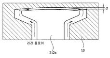
도 5를 참조하여 살펴보면, 복수 개의 투스(212)가 형성된 스테이터 코어(210)를 금형(10) 속에 배치하고, 인서트 사출 방식을 통해 인슐레이터(220)를 형성할 수 있다. 여기서, 인슐레이터(230)의 재질은 레진, 합성수지, 고무, 우레탄 중 어느 하나의 재질로 마련될 수 있으며, 복수 개의 터미널 부재와 함께 사출 성형될 수도 있다.Referring to FIG. 5, a stator core 210 having a plurality of teeth 212 may be disposed in a mold 10, and an insulator 220 may be formed through an insert injection method. Here, the material of the insulator 230 may be made of any one of resin, synthetic resin, rubber, and urethane, and may be injection molded together with the plurality of terminal members.
여기서, 스테이터 코어(210)는 스큐 타입으로 형성되기 때문에, 스테이터 코어(210)를 소정의 각도로 회전시키면서 금형(10)에 배치하는 것이 바람직하다.Here, since the stator core 210 is formed in the skew type, it is preferable to arrange | position the stator core 210 to the metal mold 10 while rotating the stator core 210 by a predetermined angle.
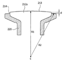
한편, 인서트 사출 방식을 통해 형성되는 인슐레이터(220)의 외반경(R2)은 투스(212)의 외반경(R1)보다 작게 형성될 수 있다. 그에 따라, 투스(212)와 인슐레이터(220) 사이에 형성되는 간극(d)이 형성될 수 있다.Meanwhile, the outer radius R2 of the insulator 220 formed through the insert injection method may be smaller than the outer radius R1 of the tooth 212. Accordingly, a gap d formed between the tooth 212 and the insulator 220 may be formed.
여기서, 투스(212)의 외반경(R1)은 중심(C)로부터 투스(212)의 외주면(213)까지의 거리를 의미하고, 인슐레이터(220)의 외반경(R2)은 중심(C)로부터 인슐레이터(220)의 외주면(221)까지의 거리를 의미할 수 있다.Here, the outer radius R1 of the tooth 212 means the distance from the center C to the outer circumferential surface 213 of the tooth 212, and the outer radius R2 of the insulator 220 is from the center C. It may mean a distance to the outer circumferential surface 221 of the insulator 220.
이하, 투스(212)와 인슐레이터(220) 사이에 형성되는 간극(d)을 설명함에 있어서 제1 투스(212a)와 제2 투스(212b)에 간극(d)이 형성될 수 있으며, 도 6 내지 도 9를 참조하여 제1 투스(212a)에 형성된 간극(d)에 대해 설명하기로 한다. Hereinafter, in describing the gap d formed between the tooth 212 and the insulator 220, a gap d may be formed between the first tooth 212a and the second tooth 212b, and FIGS. 6 to 6. A gap d formed in the first tooth 212a will be described with reference to FIG. 9.
도 6에 도시된 바와 같이, 제1 투스(212a)와 인슐레이터(220) 사이에 간극(d)이 형성되도록 레진 등을 주입하여 인슐레이터(220)를 형성할 수 있다. As illustrated in FIG. 6, an insulator 220 may be formed by injecting a resin or the like such that a gap d is formed between the first tooth 212a and the insulator 220.
도 7에 도시된 바와 같이, 투스(212)의 외반경(R1)과 인슐레이터(220)의 외반경(R2)이 동일하도록 상기 레진 등을 주입하는 경우, 금형(10)과 투스(212)의 외반경(R1) 사이의 갭(Gap)에 의해 투스(212)의 외주면으로 레진 등이 흐르게 되어 불필요한 사출물이 형성될 수 있는바, 실시예는 간극(d)이 형성되도록 레진 등을 주입하는 것이 바람직하다.As shown in FIG. 7, when the resin or the like is injected such that the outer radius R1 of the tooth 212 and the outer radius R2 of the insulator 220 are the same, the mold 10 and the tooth 212 may be separated. Resin or the like flows to the outer circumferential surface of the tooth 212 by the gap G1 between the outer radiuses R1, so that unnecessary injection molding may be formed. An embodiment of the present invention is to inject resin or the like so that a gap d is formed. desirable.
상기 간극(d)은 투스(212)의 상부와 하부에 형성될 수 있다. 도 8에 도시된 바와 같이, 상기 간극(d)은 투스(212)의 상부면과 하부면에 형성될 수 있다.The gap d may be formed above and below the tooth 212. As shown in FIG. 8, the gap d may be formed on an upper surface and a lower surface of the tooth 212.
따라서, 금형(10)의 구조를 단순화할 수 있으며, 불필요한 사출물의 발생을 최소화할 수 있다. 다만, 투스(212)의 측면에 배치되는 인슐레이터(220)의 외반경(R2)과 투스(212)의 외반경(R1)이 동일하게 되어 불필요한 사출물이 미세하게 발생할 수도 있다. 이때, 투스(212)의 높이는 투스(212)의 폭(W1, W2)보다 길기 때문에, 간극(d)을 투스(212)의 상부와 하부에 형성함으로써 불필요한 사출물의 형성을 최소화할 수 있다.Therefore, the structure of the mold 10 can be simplified, and the occurrence of unnecessary injection molding can be minimized. However, since the outer radius R2 of the insulator 220 disposed on the side of the tooth 212 and the outer radius R1 of the tooth 212 may be the same, an unnecessary injection may be minutely generated. At this time, since the height of the tooth 212 is longer than the widths W1 and W2 of the tooth 212, it is possible to minimize the formation of unnecessary injections by forming the gap d in the upper and lower portions of the tooth 212.
즉, 상기 간극(d)이 투스(212)의 상부와 하부에 형성되는 경우, 불필요한 사출물의 형성을 최소화하면서도 금형(10) 구조가 단순화할 수 있기 때문에 생산성을 향상시킬 수 있다.That is, when the gap d is formed at the upper and lower portions of the tooth 212, productivity can be improved because the mold 10 structure can be simplified while minimizing unnecessary injection molding.
도 9를 참조하여 살펴보면, 상기 간극(d)은 투스(212)의 상부와 하부뿐만 아니라 투스(212)의 측면(214)에도 형성될 수 있다. Referring to FIG. 9, the gap d may be formed on the side 214 of the tooth 212 as well as the upper and lower portions of the tooth 212.
비록, 금형(10)의 구조가 복잡화할 수 있으나, 외주면(213)에 형성되는 불필요한 사출물의 발생을 원천적으로 차단할 수 있다. Although the structure of the mold 10 may be complicated, it is possible to fundamentally block the generation of unnecessary injection moldings formed on the outer circumferential surface 213.
따라서, 상기 간극(d)이 투스(212)의 상부와 하부뿐만 아니라 투스(212)의 측면에도 형성되는 경우, 불필요한 사출물에 의해 발생하는 상기 모터(1)의 진동 또는 소음을 방지할 수 있으며, 요청된 스테이터(200)의 외경 치수에 맞는 제품을 제공할 수 있다. Therefore, when the gap d is formed on the side of the tooth 212 as well as the upper and lower portions of the tooth 212, it is possible to prevent the vibration or noise of the motor 1 caused by unnecessary injection, Products can be provided that meet the outer diameter dimensions of the requested stator 200.
한편, 상기 간극(d)이 투스(212)의 상부와 하부뿐만 아니라 투스(212)의 측면에도 형성되는 경우, 스테이터 코어(210)를 상술된 적층방식을 통해 형성할 수 있다. 즉, 본디드(Bonded) 적층 방법을 통해 스큐가 형성된 스테이터 코어(210)를 형성하고, 스큐가 형성된 스테이터 코어(210)에 인슐레이터(220)를 사출하여 스테이터(200)를 형성할 수 있다.On the other hand, when the gap (d) is formed not only on the upper and lower portions of the tooth 212, but also on the side of the tooth 212, the stator core 210 may be formed through the above-described lamination method. That is, the stator core may be formed by forming a skewed stator core 210 through a bonded lamination method, and the stator 200 may be formed by injecting the insulator 220 into the skewed stator core 210.
도 2를 참조하여 살펴보면, 전원(미도시)을 코일(230)에 인가하도록 배치되는 복수 개의 파워 터미널(400)은 인슐레이터(220)의 상부에 배치될 수 있다.Referring to FIG. 2, a plurality of power terminals 400 arranged to apply a power source (not shown) to the coil 230 may be disposed above the insulator 220.
도 10 내지 도 18을 참조하여 살펴보면, 파워 터미널(400)은 몸체(410), 핀부(420), 결합부(430), 제1 돌출부(440)를 포함할 수 있다. 또한, 파워 터미널(400)은 제2 돌출부(450)를 더 포함할 수 있다. 10 to 18, the power terminal 400 may include a body 410, a pin part 420, a coupling part 430, and a first protrusion 440. In addition, the power terminal 400 may further include a second protrusion 450.
몸체(410)는 소정의 곡률 반경(R3)을 갖도록 외측을 향하여 만곡되게 형성될 수 있다. The body 410 may be formed to be curved outwardly to have a predetermined radius of curvature R3.
그리고, 몸체(410)는, 도 10, 도 12 및 도 14에 도시된 바와 같이, 호 형상으로 형성될 수 있다. 그리고, 몸체(410)는 인슐레이터(220)의 상부에 중심(C)을 기준으로 원주 방향을 따라 배치될 수 있다.The body 410 may be formed in an arc shape, as shown in FIGS. 10, 12, and 14. In addition, the body 410 may be disposed along the circumferential direction with respect to the center C on the insulator 220.
핀부(420)는 몸체(410)의 상부로 돌출되게 형성되며, 몸체(410)와 일체로 형성될 수 있다. 즉, 핀부(420)는 몸체(410)의 일측에서 상부 방향으로 연장되게 형성될 수 있다. Pin portion 420 is formed to protrude to the upper portion of the body 410, it may be formed integrally with the body 410. That is, the pin part 420 may be formed to extend in an upward direction from one side of the body 410.
핀부(420)는 몸체(410)와 이격되게 배치되는 전원 연결부(421) 및 몸체(410)와 전원 연결부(421) 사이에 배치되는 제1 연결부(422)를 포함할 수 있다. The pin part 420 may include a power connection part 421 spaced apart from the body 410, and a first connection part 422 disposed between the body 410 and the power connection part 421.
그리고, 전원 연결부(421)와 제1 연결부(422)는 일체로 형성되며, 전원 연결부(421)의 단부는 원기둥 형상으로 형성될 수 있다. 여기서, 전원 연결부(421)는 원기둥 형상으로 형성된 것을 그 예로 하고 있으나 반드시 이에 한정되지 않으며, 전원과의 전기적 연결을 고려하여 삼각 기둥, 사각 기둥 또는 다각 기둥 형상으로 형성될 수도 있다.The power connection unit 421 and the first connection unit 422 may be integrally formed, and the end of the power connection unit 421 may be formed in a cylindrical shape. Here, the power connection portion 421 is formed as a cylindrical example, but is not limited thereto, and may be formed in a triangular pillar, a square pillar, or a polygonal pillar in consideration of electrical connection with the power source.
한편, 핀부(420)는 몸체(410)의 외주면(411)을 기준으로 외측으로 이격되게 배치될 수 있다. On the other hand, the pin portion 420 may be disposed to be spaced outwardly based on the outer peripheral surface 411 of the body 410.
여기서, 외측이라 함은 몸체(410)를 기준으로 중심(C)의 반지름 방향으로 바깥쪽을 의미하며, 내측이라 함은 몸체(410)를 기준으로 중심(C)의 반지름 방향으로 안쪽을 의미한다.Here, the outer side means the outer side in the radial direction of the center (C) relative to the body 410, the inner side means the inner side in the radial direction of the center (C) relative to the body 410. .
본 실시예의 핀부(420)는 몸체(410)의 외측에 이격되게 배치된 것을 그 예로 하고 있으나 반드시 이에 한정되는 것은 아니며 내측에 이격되게 배치될 수 있음은 물론이다. 다만, 제2 돌출부(450)와의 배치 관계에서 구조적 안정성을 위해 몸체(410)를 기준으로 서로 반대편에 이격되게 배치되는 것이 바람직하다.The pin part 420 of the present embodiment has an example of being spaced apart from the outside of the body 410, but is not necessarily limited thereto, and may be disposed to be spaced apart from the inside. However, for structural stability in the arrangement relationship with the second protrusion 450, it is preferable to be spaced apart from each other on the opposite side with respect to the body 410.
결합부(430)는 몸체(410)의 일측 단부에 형성되어 코일(230)의 단부와 결합할 수 있다. 그리고, 결합부(430)는 몸체(410)와 일체로 형성될 수 있다. Coupling portion 430 is formed at one end of the body 410 may be coupled to the end of the coil 230. In addition, the coupling part 430 may be integrally formed with the body 410.
결합부(430)는 코일(230)의 단부와 접촉결합하는 구조로 형성될 수 있다. 예컨데, 결합부(430)는 코일(230)의 단부를 감싸는 형상으로 절곡되게 형성될 수 있다. 즉, 도 2에 도시된 바와 같이, 결합부(430)는 단면이 U자형 형상으로 형성될 수 있다. 이때, 결합부(430)는 몸체(410)의 일측 단부를 내측으로 절곡하여 형성할 수 있다.Coupling portion 430 may be formed in a structure that is in contact with the end of the coil 230. For example, the coupling part 430 may be formed to be bent in a shape surrounding the end of the coil 230. That is, as shown in Figure 2, the coupling portion 430 may be formed in a U-shaped cross section. At this time, the coupling part 430 may be formed by bending one end of the body 410 inward.
한편, 결합부(430)는 몸체(410)와 소정의 높이차(h)가 형성되게 형성될 수 있다. 바람직하게, 결합부(430)의 상면(431)은 몸체(410)의 상면(413)보다 높게 배치될 수 있다. 즉, 도 12, 도 15 및 도 18에 도시된 바와 같이, 몸체(410)의 하면(414)을 기준으로 결합부(430)의 높이(h1)는 몸체(410)의 높이(h2)보다 높게 배치될 수 있다.On the other hand, the coupling portion 430 may be formed so that a predetermined height difference (h) with the body 410 is formed. Preferably, the upper surface 431 of the coupling portion 430 may be disposed higher than the upper surface 413 of the body 410. That is, as illustrated in FIGS. 12, 15, and 18, the height h1 of the coupling part 430 is higher than the height h2 of the body 410 based on the lower surface 414 of the body 410. Can be arranged.
그에 따라, 코일(230)과 결합부(430)의 퓨징시 퓨징 면적이 증가되기 때문에, 코일(230)의 단부는 결합부(430)와 용이하게 결합될 수 있다. Accordingly, since the fusing area of the coil 230 and the coupling part 430 increases in fusing, the end of the coil 230 may be easily coupled with the coupling part 430.
제1 돌출부(440) 및 제2 돌출부(450)는 몸체(410)의 하부로 돌출되게 형성될 수 있다. 여기서, 제1 돌출부(440) 및 제2 돌출부(450)는 몸체(410)와 일체로 형성될 수 있다.The first protrusion 440 and the second protrusion 450 may be formed to protrude downward from the body 410. Here, the first protrusion 440 and the second protrusion 450 may be integrally formed with the body 410.
그리고, 제1 돌출부(440) 및 제2 돌출부(450)는 인슐레이터(220)에 형성된 삽입구(222)에 끼움 결합될 수 있다. The first protrusion 440 and the second protrusion 450 may be fitted to the insertion hole 222 formed in the insulator 220.
특히, 제2 돌출부(450)는 몸체(410)를 기준으로 내측 또는 외측에 이격되게 배치될 수 있다. 예컨데, 도 11 및 도 14에 도시된 바와 같이, 제2 돌출부(450)는 몸체(410)의 내주면(412)을 기준으로 내측으로 이격되게 배치될 수 있다. In particular, the second protrusion 450 may be spaced apart from the inside or the outside of the body 410. For example, as illustrated in FIGS. 11 and 14, the second protrusion 450 may be disposed to be spaced inwardly based on the inner circumferential surface 412 of the body 410.
제2 돌출부(450)는 몸체(410)를 기준으로 이격되게 배치되는 끼움부(451) 및 몸체(410)와 끼움부(451) 사이에 배치되는 제2 연결부(452)를 포함할 수 있다.The second protrusion 450 may include a fitting part 451 spaced apart from the body 410 and a second connection part 452 disposed between the body 410 and the fitting part 451.
따라서, 제2 돌출부(450)는 원주방향을 따라 제1 돌출부(440)와 이격되게 배치되면서도 몸체(410)와 이격되게 배치되기 때문에, 파워 터미널(400)이 원주방향 또는 반지름 방향으로 진동 및 이동되는 것을 방지한다. 그에 따라, 상기 모터(1)의 회전에 따라 파워 터미널(400)의 진동에 따른 소음의 발생을 방지한다.Accordingly, since the second protrusion 450 is disposed to be spaced apart from the body 410 while being spaced apart from the first protrusion 440 along the circumferential direction, the power terminal 400 vibrates and moves in the circumferential or radial direction. Prevent it. Accordingly, generation of noise due to vibration of the power terminal 400 is prevented as the motor 1 rotates.
또한, 파워 터미널(400)을 인슐레이터(220)에 삽입 설치시, 제1 돌출부(440) 및 제2 돌출부(450)는 원주방향 및 반지름 방향으로 서로 이격되게 설치되기 때문에 조립에 대한 실수를 방지할 수 있다. In addition, when the power terminal 400 is inserted into the insulator 220 and installed, the first protrusion 440 and the second protrusion 450 may be spaced apart from each other in the circumferential direction and the radial direction to prevent a mistake in assembly. Can be.
한편, 파워 터미널(400)는, 도 10 내지 도 18에 도시된 바와 같이, 다양한 형상으로 형성될 수 있다. 이하, 파워 터미널(400)을 설명함에 있어서, 파워 터미널(400)의 실시예인 제1 파워 터미널(400a), 제2 파워 터미널(400b) 및 제3 파워 터미널(400c)로 구분하여 파워 터미널(400)의 다양한 실시예에 대한 설명을 명확히 한다.Meanwhile, the power terminal 400 may be formed in various shapes, as shown in FIGS. 10 to 18. Hereinafter, in describing the power terminal 400, the power terminal 400 is divided into a first power terminal 400a, a second power terminal 400b, and a third power terminal 400c which are embodiments of the power terminal 400. Clarification of description of various embodiments of
인슐레이터(220)의 상부에 배치되는 파워 터미널(400)은 제1 파워 터미널(400a), 제2 파워 터미널(400b) 및 제3 파워 터미널(400c) 중 적어도 하나 또는 이들의 조합에 의해 복수 개가 배치될 수 있다.A plurality of power terminals 400 disposed on the insulator 220 are arranged by at least one or a combination of the first power terminal 400a, the second power terminal 400b, and the third power terminal 400c. Can be.
도 10은 일실시예에 따른 제1 파워 터미널(400a)을 나타내는 사시도이다. 도 11은 일실시예에 따른 제1 파워 터미널(400a)을 나타내는 평면도이다. 그리고, 도 12는 일실시예에 따른 제1 파워 터미널(400a)을 반지름 방향에서 바라본 측면도이다.10 is a perspective view illustrating a first power terminal 400a according to an embodiment. 11 is a plan view illustrating a first power terminal 400a according to an embodiment. 12 is a side view of the first power terminal 400a viewed in a radial direction, according to an exemplary embodiment.
도 10 내지 도 11에 도시된 바와 같이, 제1 파워 터미널(400a)의 핀부(420)는 몸체(410)의 일측 단부에 배치될 수 있다. 그리고 몸체(410)의 타측 단부에는 결합부(430)가 배치될 수 있다. 이때, 결합부(430)는 몸체(410)의 일측 단부를 내측으로 절곡하여 형성할 수 있다. 그에 따라, 결합부(430)는 위에서 볼 때 U자형 형상으로 형성될 수 있다.10 to 11, the fin part 420 of the first power terminal 400a may be disposed at one end of the body 410. In addition, the coupling part 430 may be disposed at the other end of the body 410. At this time, the coupling part 430 may be formed by bending one end of the body 410 inward. Accordingly, the coupling part 430 may be formed in a U-shape when viewed from above.
도 12에 도시된 바와 같이, 몸체(410)의 하면(414)을 기준으로 결합부(430)의 높이(h1)는 몸체(410)의 높이(h2)보다 높게 배치될 수 있다.As shown in FIG. 12, the height h1 of the coupling part 430 may be higher than the height h2 of the body 410 based on the lower surface 414 of the body 410.
그리고, 핀부(420)는 몸체(410)의 외주면(411)에서 외측 방향으로 소정의 간격(d1)으로 이격되게 배치되며, 제2 돌출부(450)는 몸체(410)의 내주면(412)에서 내측 방향으로 소정의 간격(d2)으로 이격되게 배치된다.In addition, the pin part 420 is disposed to be spaced apart from the outer circumferential surface 411 of the body 410 by a predetermined distance d1, and the second protrusion 450 is inward from the inner circumferential surface 412 of the body 410. Are spaced apart at a predetermined interval d2 in the direction.
도 13은 다른 실시예에 따른 제2 파워 터미널(400b)을 나타내는 사시도이다. 도 14는 다른 실시예에 따른 제2 파워 터미널(400b)을 나타내는 평면도이다. 도 15는 다른 실시예에 따른 제2 파워 터미널(400b)을 반지름 방향에서 바라본 측면도이다. 13 is a perspective view illustrating a second power terminal 400b according to another embodiment. 14 is a plan view illustrating a second power terminal 400b according to another embodiment. 15 is a side view of the second power terminal 400b according to another embodiment viewed from a radial direction.
도 13 및 도 14에 도시된 바와 같이, 제2 파워 터미널(400b)의 결합부(430)는 몸체(410)의 일측 단부에 배치될 수 있다. 그리고, 핀부(420)는 몸체(410)의 일측 단부와 타측 단부 사이에 배치될 수 있다. 그리고, 제2 돌출부(450)는 몸체(410)의 타측 단부에 배치될 수 있다.As shown in FIGS. 13 and 14, the coupling part 430 of the second power terminal 400b may be disposed at one end of the body 410. In addition, the pin part 420 may be disposed between one end portion and the other end portion of the body 410. The second protrusion 450 may be disposed at the other end of the body 410.
이때, 결합부(430)는 몸체(410)의 일측 단부를 내측으로 절곡하여 형성할 수 있다. 그에 따라, 결합부(430)는 위에서 볼 때 U자형 형상으로 형성될 수 있다.At this time, the coupling part 430 may be formed by bending one end of the body 410 inward. Accordingly, the coupling part 430 may be formed in a U-shape when viewed from above.
도 15에 도시된 바와 같이, 몸체(410)의 하면(414)을 기준으로 결합부(430)의 높이(h1)는 몸체(410)의 높이(h2)보다 높게 배치될 수 있다.As shown in FIG. 15, the height h1 of the coupling part 430 may be higher than the height h2 of the body 410 based on the lower surface 414 of the body 410.
그리고, 핀부(420)는 몸체(410)의 외주면(411)에서 외측 방향으로 소정의 간격(d1)으로 이격되게 배치되며, 제2 돌출부(450)는 몸체(410)의 내주면(412)에서 내측 방향으로 소정의 간격(d2)으로 이격되게 배치된다.In addition, the pin part 420 is disposed to be spaced apart from the outer circumferential surface 411 of the body 410 by a predetermined distance d1, and the second protrusion 450 is inward from the inner circumferential surface 412 of the body 410. Are spaced apart at a predetermined interval d2 in the direction.
도 16은 또 다른 실시예에 따른 제3 파워 터미널(400c)을 나타내는 사시도이다. 도 17은 또 다른 실시예에 따른 제3 파워 터미널(400c)을 나타내는 평면도이다. 도 18은 또 다른 실시예에 따른 제3 파워 터미널(400c)을 나타내는 사시도 및 평면도이다.16 is a perspective view illustrating a third power terminal 400c according to another embodiment. 17 is a plan view illustrating a third power terminal 400c according to another embodiment. 18 is a perspective view and a plan view illustrating a third power terminal 400c according to another embodiment.
도 16 및 도 17에 도시된 바와 같이, 제3 파워 터미널(400c)은 두 개의 제1 돌출부(440)가 원주 방향을 따라 서로 이격되어 몸체(410)의 하부에 배치된다. 이때, 제3 파워 터미널(400c)의 핀부(420)는 몸체(410)의 일측 단부에 배치되고, 몸체(410)의 타측 단부에는 결합부(430)가 배치된다. 그리고, 결합부(430)는 몸체(410)의 일측 단부를 내측으로 절곡하여 형성할 수 있다. 그에 따라, 결합부(430)는 위에서 볼 때 U자형 형상으로 형성될 수 있다.16 and 17, in the third power terminal 400c, two first protrusions 440 are spaced apart from each other in the circumferential direction and disposed under the body 410. In this case, the pin part 420 of the third power terminal 400c is disposed at one end of the body 410, and the coupling part 430 is disposed at the other end of the body 410. In addition, the coupling part 430 may be formed by bending one end of the body 410 inward. Accordingly, the coupling part 430 may be formed in a U-shape when viewed from above.
도 18에 도시된 바와 같이, 몸체(410)의 하면(414)을 기준으로 결합부(430)의 높이(h1)는 몸체(410)의 높이(h2)보다 높게 배치될 수 있다.As shown in FIG. 18, the height h1 of the coupling part 430 may be higher than the height h2 of the body 410 based on the lower surface 414 of the body 410.
즉, 제1 파워 터미널(400a)과 비교해 볼 때, 제3 파워 터미널(400c)은 핀부(420)만이 몸체(410)의 외주면(411)에서 외측 방향으로 소정의 간격(d1)으로 이격되게 배치된다.That is, when compared with the first power terminal 400a, the third power terminal 400c is disposed so that only the pin portion 420 is spaced apart from the outer circumferential surface 411 of the body 410 by a predetermined distance d1 in the outward direction. do.
따라서, 상기 모터(1)는 인슐레이터(220)의 상부에 제1 파워 터미널(400a), 제2 파워 터미널(400b) 및 제3 파워 터미널(400c) 중 적어도 하나 또는 이들의 조합을 배치하여 코일(230)의 단부(231)가 노출되는 위치에 제한없이 파워 터미널(400)을 배치하여 코일(230)의 단부와 결합될 수 있다.Accordingly, the motor 1 may arrange at least one or a combination of the first power terminal 400a, the second power terminal 400b, and the third power terminal 400c on the insulator 220 to form a coil ( The power terminal 400 may be disposed and coupled to the end of the coil 230 without limiting the position where the end 231 of the 230 is exposed.
도 2를 참조하여 살펴보면, 하우징(500)은 파워 터미널(400)이 스테이터(200)에 고정될 수 있게 배치된다.Referring to FIG. 2, the housing 500 is arranged such that the power terminal 400 can be fixed to the stator 200.
하우징(500)은 원통형의 하우징 본체(510)와 하우징 본체(510)의 단부에서 외측으로 돌출되게 형성된 플랜지(520)를 포함할 수 있다. 여기서, 하우징 본체(510)와 플랜지(520)는 일체로 형성될 수 있다. The housing 500 may include a cylindrical housing body 510 and a flange 520 formed to protrude outward from an end of the housing body 510. Here, the housing body 510 and the flange 520 may be integrally formed.
하우징 본체(510)는 스테이터(200)의 외주면을 감싸도록 스테이터(200)의 외측에 배치될 수 있다. The housing body 510 may be disposed outside the stator 200 to surround the outer circumferential surface of the stator 200.
플랜지(520)는 파워 터미널(400)의 상부를 가압하게 스테이터(200)의 상부에 배치될 수 있다. 이때, 파워 터미널(400)의 핀부(420)는 플랜지(520)를 관통하도록 배치될 수 있다. 따라서, 플랜지(520)는 핀부(420)가 관통 결합되게 관통공(521)이 형성될 수 있다.The flange 520 may be disposed above the stator 200 to press the upper portion of the power terminal 400. In this case, the pin part 420 of the power terminal 400 may be disposed to pass through the flange 520. Accordingly, the through hole 521 may be formed in the flange 520 such that the pin part 420 is coupled through the flange 520.
그리고, 하우징(500)의 조립시 핀부(420)와 관통공(521)의 결합은 하우징(500) 조립 위치를 한정하게 된다.In addition, when the housing 500 is assembled, the coupling between the pin part 420 and the through hole 521 may limit the assembly position of the housing 500.
또한, 하우징(500)의 관통공(521)은 핀부(520)와 관통되게 결합함으로써, 파워 터미널(400)의 원주방향, 반지름 방향 및 축방향에 대한 진동 및 이동을 방지한다. 그에 따라, 하우징(500)은 상기 모터(1)의 회전에 따라 파워 터미널(400)의 진동을 방지하여 소음의 발생을 방지한다.In addition, the through hole 521 of the housing 500 is coupled to penetrate the pin portion 520, thereby preventing vibration and movement of the power terminal 400 in the circumferential direction, the radial direction, and the axial direction. Accordingly, the housing 500 prevents the vibration of the power terminal 400 in accordance with the rotation of the motor 1 to prevent the generation of noise.
상기 파워 터미널(400)의 핀부(420), 제1 돌출부(440) 및 제2 돌출부(450)는 몸체(410)와 일체로 형성될 수 있기 때문에, 하나의 금형에서 제작될 수 있다. 그에 따라, 파워 터미널(400)은 구조가 단순화되어 제작 및 파워 터미널(400)의 조립공정을 단순화할 수 있다. Since the pin portion 420, the first protrusion 440, and the second protrusion 450 of the power terminal 400 may be integrally formed with the body 410, they may be manufactured in one mold. Accordingly, the power terminal 400 can be simplified in structure to simplify the manufacturing and assembly process of the power terminal 400.
또한, 상기 파워 터미널(400)은 진위치도 기하공차를 만족시켜 치수 정밀도를 향상시킴으로써 수율을 증대시킬 수 있다.In addition, the power terminal 400 may increase the yield by improving the dimensional accuracy by satisfying the true position geometrical tolerance.
도 10 내지 도 18에 도시된 바와 같이, 상기 파워 터미널(400)의 핀부(420), 제1 돌출부(440) 및 제2 돌출부(450)는 인슐레이터(220)와 하우징(500)과 결합하는 3차원적 3점 지지구조를 구현하여 상기 모터(1)의 회전에 따른 진동 및 소음의 발생을 방지하고 구조적인 안정성을 확보할 수 있다.10 to 18, the pin portion 420, the first protrusion 440, and the second protrusion 450 of the power terminal 400 are coupled to the insulator 220 and the housing 500. The three-dimensional support structure can be implemented to prevent the occurrence of vibration and noise due to the rotation of the motor 1 and to ensure structural stability.
상기에서는 본 발명의 실시예를 참조하여 설명하였지만, 해당 기술 분야의 통상의 지식을 가진자는 하기의 특허 청구의 범위에 기재된 본 발명의 사상 및 영역으로부터 벗어나지 않는 범위 내에서 본 발명을 다양하게 수정 및 변경시킬 수 있음을 이해할 수 있을 것이다. 그리고, 이러한 수정과 변경에 관계된 차이점들을 첨부된 청구 범위에서 규정하는 본 발명의 범위에 포함되는 것으로 해석되어야 할 것이다.Although described above with reference to embodiments of the present invention, those of ordinary skill in the art have various modifications and changes of the present invention without departing from the spirit and scope of the present invention as set forth in the claims below. It will be appreciated that it can be changed. And differences relating to such modifications and variations should be construed as being included in the scope of the invention defined in the appended claims.
<부호의 설명><Description of the code>
1: 모터, 100: 로터, 110: 로터 코어, 120: 마그넷, 200: 스테이터, 210: 스테이터 코어, 211: 본체, 212: 투스, 220: 인슐레이터, 230: 코일, 300: 샤프트, 400: 파워 터미널, 410: 몸체, 420: 핀부, 430: 결합부, 440: 제1 돌출부, 450: 제2 돌출부, 500: 하우징 DESCRIPTION OF SYMBOLS 1: Motor, 100: rotor, 110: rotor core, 120: magnet, 200: stator, 210: stator core, 211: main body, 212: tooth, 220: insulator, 230: coil, 300: shaft, 400: power terminal 410: body, 420: pin portion, 430: coupling portion, 440: first protrusion, 450: second protrusion, 500: housing

Claims (12)

  1. 몸체;Body;
    상기 몸체에서 상부 방향으로 연장되게 형성되는 핀부;A pin part formed to extend in an upward direction from the body;
    상기 몸체의 일측에 형성되어 코일과 결합하는 결합부; A coupling part formed at one side of the body and coupled to a coil;
    상기 몸체의 하부로 돌출되게 형성된 제1 돌출부; 및A first protrusion formed to protrude downward of the body; And
    상기 몸체의 하부로 돌출되게 형성된 제2 돌출부를 포함하며, A second protrusion formed to protrude downward of the body,
    상기 제2 돌출부는 상기 몸체를 기준으로 내측 또는 외측으로 이격되게 배치되는 파워 터미널. And the second protrusion is spaced inwardly or outwardly with respect to the body.
  2. 제1항에 있어서,The method of claim 1,
    상기 몸체, 상기 핀부, 상기 결합부, 상기 제1 돌출부 및 상기 제2 돌출부는 일체로 형성되는 파워 터미널. And the body, the pin portion, the coupling portion, the first protrusion, and the second protrusion are integrally formed.
  3. 제1항에 있어서,The method of claim 1,
    상기 몸체는 소정의 곡률 반경(R3)을 갖도록 만곡되게 형성된 파워 터미널.And the body is formed to be curved to have a predetermined radius of curvature (R3).
  4. 제3항에 있어서,The method of claim 3,
    상기 몸체를 기준으로 상기 핀부는 외측으로 이격되게 배치되는 파워 터미널.The pin terminal is spaced apart from the outside based on the body.
  5. 제4항에 있어서,The method of claim 4, wherein
    상기 몸체를 기준으로 상기 제2 돌출부는 상기 핀부의 반대편에 배치되는 파워 터미널. The second protrusion relative to the body is disposed on the opposite side of the pin portion.
  6. 제4항에 있어서,The method of claim 4, wherein
    상기 핀부는 상기 몸체와 이격되게 배치되는 전원 연결부; 및The pin portion is a power connection portion spaced apart from the body; And
    상기 몸체와 상기 전원 연결부 사이에 배치되는 제1 연결부를 포함하는 파워 터미널.And a first connection portion disposed between the body and the power connection portion.
  7. 제6항에 있어서,The method of claim 6,
    상기 전원 연결부의 단부는 원기둥 형상으로 형성되는 파워 터미널.An end portion of the power connection portion is formed in a cylindrical shape.
  8. 제1항에 있어서,The method of claim 1,
    상기 몸체의 하면을 기준으로 상기 결합부의 높이(h1)는 상기 몸체의 높이(h2)보다 높게 배치되는 파워 터미널.The height (h1) of the coupling portion relative to the lower surface of the body is disposed higher than the height (h2) of the body.
  9. 로터;Rotor;
    상기 로터의 외측에 배치되는 스테이터;A stator disposed outside the rotor;
    상기 로터의 내측에 배치되는 샤프트; 및A shaft disposed inside the rotor; And
    상기 스테이터의 상부에 배치되는 터미널을 포함하며, It includes a terminal disposed on the top of the stator,
    상기 터미널은,The terminal,
    몸체;Body;
    상기 몸체에서 상부 방향으로 연장되게 형성되는 핀부;A pin part formed to extend in an upward direction from the body;
    상기 몸체의 일측에 형성되어 코일과 결합하는 결합부; A coupling part formed at one side of the body and coupled to a coil;
    상기 몸체의 하부로 돌출되게 형성된 제1 돌출부; 및A first protrusion formed to protrude downward of the body; And
    상기 몸체의 하부로 돌출되게 형성된 제2 돌출부를 포함하며, A second protrusion formed to protrude downward of the body,
    상기 몸체를 기준으로 상기 제2 돌출부는 내측 또는 외측으로 이격되게 배치되는 모터.The second protrusion is spaced inwardly or outwardly with respect to the body.
  10. 제9항에 있어서,The method of claim 9,
    상기 스테이터의 인슐레이터 상부에 형성된 삽입구에는 상기 제1 돌출부 및 상기 제2 돌출부가 결합되며,The first protrusion and the second protrusion are coupled to an insertion hole formed on the insulator of the stator.
    상기 몸체를 기준으로 상기 제2 돌출부는 내측으로 이격되게 배치되는 모터. The second protrusion is disposed to be spaced inward with respect to the body.
  11. 제9항에 있어서, The method of claim 9,
    상기 스테이터는, The stator is,
    원통형의 본체와 상기 본체의 원주방향을 따라 상기 본체의 중심에서 방사방향으로 돌출되게 형성된 복수 개의 투스를 포함하는 스큐 타입의 스테이터 코어; A skew type stator core comprising a cylindrical body and a plurality of teeth formed to protrude radially from the center of the body along the circumferential direction of the body;
    상기 스테이터 코어에 배치되는 인슐레이터; 및An insulator disposed on the stator core; And
    상기 인슐레이터에 권선되는 코일을 포함하며,A coil wound around the insulator,
    상기 제1 돌출부와 상기 제2 돌출부는 상기 인슐레이터에 형성된 삽입구에 끼움 결합되는 모터.The first protrusion and the second protrusion is fitted to the insertion hole formed in the insulator motor.
  12. 제11항에 있어서,The method of claim 11,
    상기 스테이터의 외측에 배치되는 원통형의 하우징 본체; 및 상기 하우징 본체의 단부에서 외측으로 돌출되게 형성된 플랜지;를 포함하는 하우징을 더 포함하며,A cylindrical housing body disposed outside the stator; And a flange formed to protrude outward from an end of the housing body.
    상기 플랜지에 형성된 관통공에 상기 핀부가 관통하여 결합되는 모터.The pin is coupled to the through hole formed in the flange through the motor.
PCT/KR2017/004221 2016-04-27 2017-04-20 Power terminal and motor including same WO2017188659A1 (en)

Priority Applications (4)

Application Number Priority Date Filing Date Title
JP2018554465A JP6991998B2 (en) 2016-04-27 2017-04-20 Power terminal and motor including it
EP17789844.2A EP3451508B1 (en) 2016-04-27 2017-04-20 Power terminal and motor including same
CN201780026246.8A CN109075654B (en) 2016-04-27 2017-04-20 Power supply terminal and motor comprising same
US16/096,567 US11152824B2 (en) 2016-04-27 2017-04-20 Power terminal and motor including same

Applications Claiming Priority (2)

Application Number Priority Date Filing Date Title
KR1020160051508A KR20170122486A (en) 2016-04-27 2016-04-27 Terminal and Motor having the same
KR10-2016-0051508 2016-04-27

Publications (1)

Publication Number Publication Date
WO2017188659A1 true WO2017188659A1 (en) 2017-11-02

Family

ID=60159870

Family Applications (1)

Application Number Title Priority Date Filing Date
PCT/KR2017/004221 WO2017188659A1 (en) 2016-04-27 2017-04-20 Power terminal and motor including same

Country Status (6)

Country Link
US (1) US11152824B2 (en)
EP (1) EP3451508B1 (en)
JP (1) JP6991998B2 (en)
KR (1) KR20170122486A (en)
CN (1) CN109075654B (en)
WO (1) WO2017188659A1 (en)

Cited By (1)

* Cited by examiner, † Cited by third party
Publication number Priority date Publication date Assignee Title
CN113196621A (en) * 2018-12-11 2021-07-30 Lg伊诺特有限公司 Electric machine

Families Citing this family (6)

* Cited by examiner, † Cited by third party
Publication number Priority date Publication date Assignee Title
JPWO2018180798A1 (en) * 2017-03-31 2020-02-06 日本電産株式会社 Motor and electric power steering device
KR102547568B1 (en) * 2017-12-04 2023-06-26 엘지이노텍 주식회사 Motor
KR20200079641A (en) * 2018-12-26 2020-07-06 엘지이노텍 주식회사 Motor
DE102020100963B4 (en) 2020-01-16 2024-03-28 Audi Aktiengesellschaft Electric machine and motor vehicle
JP2022108590A (en) * 2021-01-13 2022-07-26 株式会社デンソー Stator and rotary electric machine
US20220247270A1 (en) 2021-02-02 2022-08-04 Black & Decker Inc. High-power motor for a body-grip power tool

Citations (5)

* Cited by examiner, † Cited by third party
Publication number Priority date Publication date Assignee Title
JP2007318885A (en) * 2006-05-25 2007-12-06 Mabuchi Motor Co Ltd Brushless motor
KR20120001891A (en) * 2010-06-30 2012-01-05 뉴모텍(주) Coil wiring structure of stator core with printed circuit board
JP2013162648A (en) * 2012-02-06 2013-08-19 Aisan Ind Co Ltd Motor and electric pump
JP2014176207A (en) * 2013-03-08 2014-09-22 Kayaba Ind Co Ltd Busbar unit
JP2016019421A (en) * 2014-07-10 2016-02-01 Kyb株式会社 Bus bar unit, rotary electric machine with the same and method of manufacturing the bus bar unit

Family Cites Families (12)

* Cited by examiner, † Cited by third party
Publication number Priority date Publication date Assignee Title
JPS6192134A (en) 1984-10-11 1986-05-10 Matsushita Electric Ind Co Ltd Motor
JP2802082B2 (en) 1988-10-28 1998-09-21 松下精工株式会社 Motor stator core
JP2583638Y2 (en) 1992-05-15 1998-10-27 日本精工株式会社 Inner rotor type brushless motor
JP3791492B2 (en) 2002-12-25 2006-06-28 株式会社日立製作所 Rotating electric machine, electric vehicle, and resin insert molding method
JP2004336966A (en) * 2003-05-12 2004-11-25 Mitsubishi Electric Corp Rotary electric machine
WO2009025144A1 (en) * 2007-08-17 2009-02-26 Kabushiki Kaisha Yaskawa Denki Stator and rotating electrical machine using the same
JP2012196018A (en) 2011-03-15 2012-10-11 Toyota Auto Body Co Ltd Wiring structure of three-phase motor
JP2013042633A (en) 2011-08-19 2013-02-28 Nippon Densan Corp Motor
US20140028127A1 (en) * 2012-07-25 2014-01-30 Bradley Duane Chamberlin Buss bar assembly having alignment and retention feature
JP2014093807A (en) * 2012-11-01 2014-05-19 Aisan Ind Co Ltd Stator terminal
JP6190599B2 (en) * 2013-03-08 2017-08-30 Kyb株式会社 Manufacturing method of bus bar unit
JP6267907B2 (en) * 2013-09-26 2018-01-24 株式会社ミツバ Busbar unit and brushless motor

Patent Citations (5)

* Cited by examiner, † Cited by third party
Publication number Priority date Publication date Assignee Title
JP2007318885A (en) * 2006-05-25 2007-12-06 Mabuchi Motor Co Ltd Brushless motor
KR20120001891A (en) * 2010-06-30 2012-01-05 뉴모텍(주) Coil wiring structure of stator core with printed circuit board
JP2013162648A (en) * 2012-02-06 2013-08-19 Aisan Ind Co Ltd Motor and electric pump
JP2014176207A (en) * 2013-03-08 2014-09-22 Kayaba Ind Co Ltd Busbar unit
JP2016019421A (en) * 2014-07-10 2016-02-01 Kyb株式会社 Bus bar unit, rotary electric machine with the same and method of manufacturing the bus bar unit

Non-Patent Citations (1)

* Cited by examiner, † Cited by third party
Title
See also references of EP3451508A4 *

Cited By (4)

* Cited by examiner, † Cited by third party
Publication number Priority date Publication date Assignee Title
CN113196621A (en) * 2018-12-11 2021-07-30 Lg伊诺特有限公司 Electric machine
EP3876397A4 (en) * 2018-12-11 2022-08-10 LG Innotek Co., Ltd. Motor
US11855504B2 (en) 2018-12-11 2023-12-26 Lg Innotek Co., Ltd. Motor
CN113196621B (en) * 2018-12-11 2024-04-12 Lg伊诺特有限公司 Motor with a motor housing

Also Published As

Publication number Publication date
US11152824B2 (en) 2021-10-19
US20190140496A1 (en) 2019-05-09
CN109075654A (en) 2018-12-21
EP3451508A1 (en) 2019-03-06
JP2019516336A (en) 2019-06-13
EP3451508B1 (en) 2023-01-18
EP3451508A4 (en) 2019-12-25
CN109075654B (en) 2021-01-26
KR20170122486A (en) 2017-11-06
JP6991998B2 (en) 2022-01-13

Similar Documents

Publication Publication Date Title
WO2017188659A1 (en) Power terminal and motor including same
WO2018044027A1 (en) Stator, and motor comprising same
WO2011158993A1 (en) Brushless dc motor having a slotless stator
EP3476021A1 (en) Stator and motor having the same
WO2018101638A1 (en) Cover assembly, motor and electric steering device including same
WO2020055150A1 (en) Motor
WO2020060093A1 (en) Motor
WO2018016744A1 (en) Motor
WO2018139791A1 (en) Motor
WO2020050535A1 (en) Motor
WO2018012885A1 (en) Rotor and motor comprising same
WO2020045936A1 (en) Motor
EP3672038A1 (en) Permanent magnet rotor and its manufacturing method
WO2021141230A1 (en) Motor
WO2019124799A1 (en) Rotor and motor having same
WO2020055067A1 (en) Motor
WO2019027196A1 (en) Rotor and motor comprising same
WO2021157935A1 (en) Motor
WO2021141299A1 (en) Motor
WO2020145538A1 (en) Motor
WO2020085744A1 (en) Motor
WO2020149626A1 (en) Rotor and motor comprising same
WO2021187820A1 (en) Motor using asymmetric stator shoes and manufacturing method therefor
WO2022145977A1 (en) Cover and motor comprising same
WO2020045937A1 (en) Motor

Legal Events

Date Code Title Description
ENP Entry into the national phase

Ref document number: 2018554465

Country of ref document: JP

Kind code of ref document: A

NENP Non-entry into the national phase

Ref country code: DE

WWE Wipo information: entry into national phase

Ref document number: 2017789844

Country of ref document: EP

ENP Entry into the national phase

Ref document number: 2017789844

Country of ref document: EP

Effective date: 20181127

121 Ep: the epo has been informed by wipo that ep was designated in this application

Ref document number: 17789844

Country of ref document: EP

Kind code of ref document: A1