WO2017188193A1 - 制御システム及び作業機械 - Google Patents
制御システム及び作業機械 Download PDFInfo
- Publication number
- WO2017188193A1 WO2017188193A1 PCT/JP2017/016244 JP2017016244W WO2017188193A1 WO 2017188193 A1 WO2017188193 A1 WO 2017188193A1 JP 2017016244 W JP2017016244 W JP 2017016244W WO 2017188193 A1 WO2017188193 A1 WO 2017188193A1
- Authority
- WO
- WIPO (PCT)
- Prior art keywords
- output
- hydraulic
- engine
- pump
- flow rate
- Prior art date
- Legal status (The legal status is an assumption and is not a legal conclusion. Google has not performed a legal analysis and makes no representation as to the accuracy of the status listed.)
- Ceased
Links
Images







Classifications
-
- E—FIXED CONSTRUCTIONS
- E02—HYDRAULIC ENGINEERING; FOUNDATIONS; SOIL SHIFTING
- E02F—DREDGING; SOIL-SHIFTING
- E02F9/00—Component parts of dredgers or soil-shifting machines, not restricted to one of the kinds covered by groups E02F3/00 - E02F7/00
- E02F9/20—Drives; Control devices
- E02F9/2058—Electric or electro-mechanical or mechanical control devices of vehicle sub-units
- E02F9/2062—Control of propulsion units
- E02F9/2066—Control of propulsion units of the type combustion engines
-
- E—FIXED CONSTRUCTIONS
- E02—HYDRAULIC ENGINEERING; FOUNDATIONS; SOIL SHIFTING
- E02F—DREDGING; SOIL-SHIFTING
- E02F9/00—Component parts of dredgers or soil-shifting machines, not restricted to one of the kinds covered by groups E02F3/00 - E02F7/00
- E02F9/20—Drives; Control devices
- E02F9/22—Hydraulic or pneumatic drives
- E02F9/2246—Control of prime movers, e.g. depending on the hydraulic load of work tools
-
- E—FIXED CONSTRUCTIONS
- E02—HYDRAULIC ENGINEERING; FOUNDATIONS; SOIL SHIFTING
- E02F—DREDGING; SOIL-SHIFTING
- E02F9/00—Component parts of dredgers or soil-shifting machines, not restricted to one of the kinds covered by groups E02F3/00 - E02F7/00
- E02F9/20—Drives; Control devices
- E02F9/22—Hydraulic or pneumatic drives
- E02F9/2221—Control of flow rate; Load sensing arrangements
-
- E—FIXED CONSTRUCTIONS
- E02—HYDRAULIC ENGINEERING; FOUNDATIONS; SOIL SHIFTING
- E02F—DREDGING; SOIL-SHIFTING
- E02F9/00—Component parts of dredgers or soil-shifting machines, not restricted to one of the kinds covered by groups E02F3/00 - E02F7/00
- E02F9/20—Drives; Control devices
- E02F9/22—Hydraulic or pneumatic drives
- E02F9/2221—Control of flow rate; Load sensing arrangements
- E02F9/2239—Control of flow rate; Load sensing arrangements using two or more pumps with cross-assistance
-
- E—FIXED CONSTRUCTIONS
- E02—HYDRAULIC ENGINEERING; FOUNDATIONS; SOIL SHIFTING
- E02F—DREDGING; SOIL-SHIFTING
- E02F9/00—Component parts of dredgers or soil-shifting machines, not restricted to one of the kinds covered by groups E02F3/00 - E02F7/00
- E02F9/20—Drives; Control devices
- E02F9/22—Hydraulic or pneumatic drives
- E02F9/2264—Arrangements or adaptations of elements for hydraulic drives
- E02F9/2267—Valves or distributors
-
- E—FIXED CONSTRUCTIONS
- E02—HYDRAULIC ENGINEERING; FOUNDATIONS; SOIL SHIFTING
- E02F—DREDGING; SOIL-SHIFTING
- E02F9/00—Component parts of dredgers or soil-shifting machines, not restricted to one of the kinds covered by groups E02F3/00 - E02F7/00
- E02F9/20—Drives; Control devices
- E02F9/22—Hydraulic or pneumatic drives
- E02F9/2264—Arrangements or adaptations of elements for hydraulic drives
- E02F9/2271—Actuators and supports therefor and protection therefor
-
- E—FIXED CONSTRUCTIONS
- E02—HYDRAULIC ENGINEERING; FOUNDATIONS; SOIL SHIFTING
- E02F—DREDGING; SOIL-SHIFTING
- E02F9/00—Component parts of dredgers or soil-shifting machines, not restricted to one of the kinds covered by groups E02F3/00 - E02F7/00
- E02F9/20—Drives; Control devices
- E02F9/22—Hydraulic or pneumatic drives
- E02F9/2278—Hydraulic circuits
- E02F9/2292—Systems with two or more pumps
-
- E—FIXED CONSTRUCTIONS
- E02—HYDRAULIC ENGINEERING; FOUNDATIONS; SOIL SHIFTING
- E02F—DREDGING; SOIL-SHIFTING
- E02F9/00—Component parts of dredgers or soil-shifting machines, not restricted to one of the kinds covered by groups E02F3/00 - E02F7/00
- E02F9/20—Drives; Control devices
- E02F9/22—Hydraulic or pneumatic drives
- E02F9/2278—Hydraulic circuits
- E02F9/2296—Systems with a variable displacement pump
-
- F—MECHANICAL ENGINEERING; LIGHTING; HEATING; WEAPONS; BLASTING
- F02—COMBUSTION ENGINES; HOT-GAS OR COMBUSTION-PRODUCT ENGINE PLANTS
- F02D—CONTROLLING COMBUSTION ENGINES
- F02D29/00—Controlling engines, such controlling being peculiar to the devices driven thereby, the devices being other than parts or accessories essential to engine operation, e.g. controlling of engines by signals external thereto
- F02D29/04—Controlling engines, such controlling being peculiar to the devices driven thereby, the devices being other than parts or accessories essential to engine operation, e.g. controlling of engines by signals external thereto peculiar to engines driving pumps
-
- F—MECHANICAL ENGINEERING; LIGHTING; HEATING; WEAPONS; BLASTING
- F02—COMBUSTION ENGINES; HOT-GAS OR COMBUSTION-PRODUCT ENGINE PLANTS
- F02D—CONTROLLING COMBUSTION ENGINES
- F02D41/00—Electrical control of supply of combustible mixture or its constituents
- F02D41/02—Circuit arrangements for generating control signals
- F02D41/021—Introducing corrections for particular conditions exterior to the engine
-
- F—MECHANICAL ENGINEERING; LIGHTING; HEATING; WEAPONS; BLASTING
- F15—FLUID-PRESSURE ACTUATORS; HYDRAULICS OR PNEUMATICS IN GENERAL
- F15B—SYSTEMS ACTING BY MEANS OF FLUIDS IN GENERAL; FLUID-PRESSURE ACTUATORS, e.g. SERVOMOTORS; DETAILS OF FLUID-PRESSURE SYSTEMS, NOT OTHERWISE PROVIDED FOR
- F15B11/00—Servomotor systems without provision for follow-up action; Circuits therefor
- F15B11/02—Systems essentially incorporating special features for controlling the speed or actuating force of an output member
- F15B11/04—Systems essentially incorporating special features for controlling the speed or actuating force of an output member for controlling the speed
- F15B11/042—Systems essentially incorporating special features for controlling the speed or actuating force of an output member for controlling the speed by means in the feed line, i.e. "meter in"
- F15B11/0423—Systems essentially incorporating special features for controlling the speed or actuating force of an output member for controlling the speed by means in the feed line, i.e. "meter in" by controlling pump output or bypass, other than to maintain constant speed
-
- F—MECHANICAL ENGINEERING; LIGHTING; HEATING; WEAPONS; BLASTING
- F15—FLUID-PRESSURE ACTUATORS; HYDRAULICS OR PNEUMATICS IN GENERAL
- F15B—SYSTEMS ACTING BY MEANS OF FLUIDS IN GENERAL; FLUID-PRESSURE ACTUATORS, e.g. SERVOMOTORS; DETAILS OF FLUID-PRESSURE SYSTEMS, NOT OTHERWISE PROVIDED FOR
- F15B11/00—Servomotor systems without provision for follow-up action; Circuits therefor
- F15B11/16—Servomotor systems without provision for follow-up action; Circuits therefor with two or more servomotors
- F15B11/161—Servomotor systems without provision for follow-up action; Circuits therefor with two or more servomotors with sensing of servomotor demand or load
- F15B11/165—Servomotor systems without provision for follow-up action; Circuits therefor with two or more servomotors with sensing of servomotor demand or load for adjusting the pump output or bypass in response to demand
-
- F—MECHANICAL ENGINEERING; LIGHTING; HEATING; WEAPONS; BLASTING
- F15—FLUID-PRESSURE ACTUATORS; HYDRAULICS OR PNEUMATICS IN GENERAL
- F15B—SYSTEMS ACTING BY MEANS OF FLUIDS IN GENERAL; FLUID-PRESSURE ACTUATORS, e.g. SERVOMOTORS; DETAILS OF FLUID-PRESSURE SYSTEMS, NOT OTHERWISE PROVIDED FOR
- F15B11/00—Servomotor systems without provision for follow-up action; Circuits therefor
- F15B11/16—Servomotor systems without provision for follow-up action; Circuits therefor with two or more servomotors
- F15B11/17—Servomotor systems without provision for follow-up action; Circuits therefor with two or more servomotors using two or more pumps
-
- F—MECHANICAL ENGINEERING; LIGHTING; HEATING; WEAPONS; BLASTING
- F15—FLUID-PRESSURE ACTUATORS; HYDRAULICS OR PNEUMATICS IN GENERAL
- F15B—SYSTEMS ACTING BY MEANS OF FLUIDS IN GENERAL; FLUID-PRESSURE ACTUATORS, e.g. SERVOMOTORS; DETAILS OF FLUID-PRESSURE SYSTEMS, NOT OTHERWISE PROVIDED FOR
- F15B2211/00—Circuits for servomotor systems
- F15B2211/20—Fluid pressure source, e.g. accumulator or variable axial piston pump
- F15B2211/205—Systems with pumps
- F15B2211/20507—Type of prime mover
- F15B2211/20515—Electric motor
-
- F—MECHANICAL ENGINEERING; LIGHTING; HEATING; WEAPONS; BLASTING
- F15—FLUID-PRESSURE ACTUATORS; HYDRAULICS OR PNEUMATICS IN GENERAL
- F15B—SYSTEMS ACTING BY MEANS OF FLUIDS IN GENERAL; FLUID-PRESSURE ACTUATORS, e.g. SERVOMOTORS; DETAILS OF FLUID-PRESSURE SYSTEMS, NOT OTHERWISE PROVIDED FOR
- F15B2211/00—Circuits for servomotor systems
- F15B2211/20—Fluid pressure source, e.g. accumulator or variable axial piston pump
- F15B2211/205—Systems with pumps
- F15B2211/20507—Type of prime mover
- F15B2211/20523—Internal combustion engine
-
- F—MECHANICAL ENGINEERING; LIGHTING; HEATING; WEAPONS; BLASTING
- F15—FLUID-PRESSURE ACTUATORS; HYDRAULICS OR PNEUMATICS IN GENERAL
- F15B—SYSTEMS ACTING BY MEANS OF FLUIDS IN GENERAL; FLUID-PRESSURE ACTUATORS, e.g. SERVOMOTORS; DETAILS OF FLUID-PRESSURE SYSTEMS, NOT OTHERWISE PROVIDED FOR
- F15B2211/00—Circuits for servomotor systems
- F15B2211/20—Fluid pressure source, e.g. accumulator or variable axial piston pump
- F15B2211/205—Systems with pumps
- F15B2211/2053—Type of pump
- F15B2211/20546—Type of pump variable capacity
-
- F—MECHANICAL ENGINEERING; LIGHTING; HEATING; WEAPONS; BLASTING
- F15—FLUID-PRESSURE ACTUATORS; HYDRAULICS OR PNEUMATICS IN GENERAL
- F15B—SYSTEMS ACTING BY MEANS OF FLUIDS IN GENERAL; FLUID-PRESSURE ACTUATORS, e.g. SERVOMOTORS; DETAILS OF FLUID-PRESSURE SYSTEMS, NOT OTHERWISE PROVIDED FOR
- F15B2211/00—Circuits for servomotor systems
- F15B2211/20—Fluid pressure source, e.g. accumulator or variable axial piston pump
- F15B2211/205—Systems with pumps
- F15B2211/20576—Systems with pumps with multiple pumps
-
- F—MECHANICAL ENGINEERING; LIGHTING; HEATING; WEAPONS; BLASTING
- F15—FLUID-PRESSURE ACTUATORS; HYDRAULICS OR PNEUMATICS IN GENERAL
- F15B—SYSTEMS ACTING BY MEANS OF FLUIDS IN GENERAL; FLUID-PRESSURE ACTUATORS, e.g. SERVOMOTORS; DETAILS OF FLUID-PRESSURE SYSTEMS, NOT OTHERWISE PROVIDED FOR
- F15B2211/00—Circuits for servomotor systems
- F15B2211/20—Fluid pressure source, e.g. accumulator or variable axial piston pump
- F15B2211/275—Control of the prime mover, e.g. hydraulic control
-
- F—MECHANICAL ENGINEERING; LIGHTING; HEATING; WEAPONS; BLASTING
- F15—FLUID-PRESSURE ACTUATORS; HYDRAULICS OR PNEUMATICS IN GENERAL
- F15B—SYSTEMS ACTING BY MEANS OF FLUIDS IN GENERAL; FLUID-PRESSURE ACTUATORS, e.g. SERVOMOTORS; DETAILS OF FLUID-PRESSURE SYSTEMS, NOT OTHERWISE PROVIDED FOR
- F15B2211/00—Circuits for servomotor systems
- F15B2211/30—Directional control
- F15B2211/305—Directional control characterised by the type of valves
- F15B2211/3056—Assemblies of multiple valves
- F15B2211/3059—Assemblies of multiple valves having multiple valves for multiple output members
- F15B2211/30595—Assemblies of multiple valves having multiple valves for multiple output members with additional valves between the groups of valves for multiple output members
-
- F—MECHANICAL ENGINEERING; LIGHTING; HEATING; WEAPONS; BLASTING
- F15—FLUID-PRESSURE ACTUATORS; HYDRAULICS OR PNEUMATICS IN GENERAL
- F15B—SYSTEMS ACTING BY MEANS OF FLUIDS IN GENERAL; FLUID-PRESSURE ACTUATORS, e.g. SERVOMOTORS; DETAILS OF FLUID-PRESSURE SYSTEMS, NOT OTHERWISE PROVIDED FOR
- F15B2211/00—Circuits for servomotor systems
- F15B2211/40—Flow control
- F15B2211/405—Flow control characterised by the type of flow control means or valve
- F15B2211/40515—Flow control characterised by the type of flow control means or valve with variable throttles or orifices
-
- F—MECHANICAL ENGINEERING; LIGHTING; HEATING; WEAPONS; BLASTING
- F15—FLUID-PRESSURE ACTUATORS; HYDRAULICS OR PNEUMATICS IN GENERAL
- F15B—SYSTEMS ACTING BY MEANS OF FLUIDS IN GENERAL; FLUID-PRESSURE ACTUATORS, e.g. SERVOMOTORS; DETAILS OF FLUID-PRESSURE SYSTEMS, NOT OTHERWISE PROVIDED FOR
- F15B2211/00—Circuits for servomotor systems
- F15B2211/40—Flow control
- F15B2211/415—Flow control characterised by the connections of the flow control means in the circuit
- F15B2211/41509—Flow control characterised by the connections of the flow control means in the circuit being connected to a pressure source and a directional control valve
- F15B2211/41518—Flow control characterised by the connections of the flow control means in the circuit being connected to a pressure source and a directional control valve being connected to multiple pressure sources
-
- F—MECHANICAL ENGINEERING; LIGHTING; HEATING; WEAPONS; BLASTING
- F15—FLUID-PRESSURE ACTUATORS; HYDRAULICS OR PNEUMATICS IN GENERAL
- F15B—SYSTEMS ACTING BY MEANS OF FLUIDS IN GENERAL; FLUID-PRESSURE ACTUATORS, e.g. SERVOMOTORS; DETAILS OF FLUID-PRESSURE SYSTEMS, NOT OTHERWISE PROVIDED FOR
- F15B2211/00—Circuits for servomotor systems
- F15B2211/60—Circuit components or control therefor
- F15B2211/63—Electronic controllers
- F15B2211/6303—Electronic controllers using input signals
- F15B2211/6306—Electronic controllers using input signals representing a pressure
- F15B2211/6309—Electronic controllers using input signals representing a pressure the pressure being a pressure source supply pressure
-
- F—MECHANICAL ENGINEERING; LIGHTING; HEATING; WEAPONS; BLASTING
- F15—FLUID-PRESSURE ACTUATORS; HYDRAULICS OR PNEUMATICS IN GENERAL
- F15B—SYSTEMS ACTING BY MEANS OF FLUIDS IN GENERAL; FLUID-PRESSURE ACTUATORS, e.g. SERVOMOTORS; DETAILS OF FLUID-PRESSURE SYSTEMS, NOT OTHERWISE PROVIDED FOR
- F15B2211/00—Circuits for servomotor systems
- F15B2211/60—Circuit components or control therefor
- F15B2211/63—Electronic controllers
- F15B2211/6303—Electronic controllers using input signals
- F15B2211/6306—Electronic controllers using input signals representing a pressure
- F15B2211/6313—Electronic controllers using input signals representing a pressure the pressure being a load pressure
-
- F—MECHANICAL ENGINEERING; LIGHTING; HEATING; WEAPONS; BLASTING
- F15—FLUID-PRESSURE ACTUATORS; HYDRAULICS OR PNEUMATICS IN GENERAL
- F15B—SYSTEMS ACTING BY MEANS OF FLUIDS IN GENERAL; FLUID-PRESSURE ACTUATORS, e.g. SERVOMOTORS; DETAILS OF FLUID-PRESSURE SYSTEMS, NOT OTHERWISE PROVIDED FOR
- F15B2211/00—Circuits for servomotor systems
- F15B2211/60—Circuit components or control therefor
- F15B2211/63—Electronic controllers
- F15B2211/6303—Electronic controllers using input signals
- F15B2211/6346—Electronic controllers using input signals representing a state of input means, e.g. joystick position
-
- F—MECHANICAL ENGINEERING; LIGHTING; HEATING; WEAPONS; BLASTING
- F15—FLUID-PRESSURE ACTUATORS; HYDRAULICS OR PNEUMATICS IN GENERAL
- F15B—SYSTEMS ACTING BY MEANS OF FLUIDS IN GENERAL; FLUID-PRESSURE ACTUATORS, e.g. SERVOMOTORS; DETAILS OF FLUID-PRESSURE SYSTEMS, NOT OTHERWISE PROVIDED FOR
- F15B2211/00—Circuits for servomotor systems
- F15B2211/60—Circuit components or control therefor
- F15B2211/665—Methods of control using electronic components
- F15B2211/6651—Control of the prime mover, e.g. control of the output torque or rotational speed
-
- F—MECHANICAL ENGINEERING; LIGHTING; HEATING; WEAPONS; BLASTING
- F15—FLUID-PRESSURE ACTUATORS; HYDRAULICS OR PNEUMATICS IN GENERAL
- F15B—SYSTEMS ACTING BY MEANS OF FLUIDS IN GENERAL; FLUID-PRESSURE ACTUATORS, e.g. SERVOMOTORS; DETAILS OF FLUID-PRESSURE SYSTEMS, NOT OTHERWISE PROVIDED FOR
- F15B2211/00—Circuits for servomotor systems
- F15B2211/60—Circuit components or control therefor
- F15B2211/665—Methods of control using electronic components
- F15B2211/6655—Power control, e.g. combined pressure and flow rate control
-
- F—MECHANICAL ENGINEERING; LIGHTING; HEATING; WEAPONS; BLASTING
- F15—FLUID-PRESSURE ACTUATORS; HYDRAULICS OR PNEUMATICS IN GENERAL
- F15B—SYSTEMS ACTING BY MEANS OF FLUIDS IN GENERAL; FLUID-PRESSURE ACTUATORS, e.g. SERVOMOTORS; DETAILS OF FLUID-PRESSURE SYSTEMS, NOT OTHERWISE PROVIDED FOR
- F15B2211/00—Circuits for servomotor systems
- F15B2211/60—Circuit components or control therefor
- F15B2211/665—Methods of control using electronic components
- F15B2211/6658—Control using different modes, e.g. four-quadrant-operation, working mode and transportation mode
-
- F—MECHANICAL ENGINEERING; LIGHTING; HEATING; WEAPONS; BLASTING
- F15—FLUID-PRESSURE ACTUATORS; HYDRAULICS OR PNEUMATICS IN GENERAL
- F15B—SYSTEMS ACTING BY MEANS OF FLUIDS IN GENERAL; FLUID-PRESSURE ACTUATORS, e.g. SERVOMOTORS; DETAILS OF FLUID-PRESSURE SYSTEMS, NOT OTHERWISE PROVIDED FOR
- F15B2211/00—Circuits for servomotor systems
- F15B2211/70—Output members, e.g. hydraulic motors or cylinders or control therefor
- F15B2211/71—Multiple output members, e.g. multiple hydraulic motors or cylinders
- F15B2211/7142—Multiple output members, e.g. multiple hydraulic motors or cylinders the output members being arranged in multiple groups
Definitions
- the present invention relates to a control system and a work machine.
- a hydraulic excavator is known as a kind of work machine having a work machine.
- the working machine of the hydraulic excavator is driven by a hydraulic cylinder.
- the hydraulic cylinder is operated by hydraulic oil discharged from the hydraulic pump.
- Patent Document 1 discloses a hydraulic control device having a merging / separating valve that switches between a merging state in which hydraulic oil discharged from a first hydraulic pump and a hydraulic oil discharged from a second hydraulic pump merge and a divergence state that does not merge. Are listed.
- the first hydraulic actuator is operated by the hydraulic oil discharged from the first hydraulic pump
- the second hydraulic actuator is operated by the hydraulic oil discharged from the second hydraulic pump.
- the first hydraulic pump and the second hydraulic pump are each driven by the engine.
- a shunt state for example, when the load acting on the first hydraulic actuator is large, it is necessary to increase the output of the engine and increase the discharge pressure of the hydraulic oil discharged from the first hydraulic pump.
- the engine output is increased to increase the discharge pressure of the hydraulic oil discharged from the first hydraulic pump. Otherwise, the engine will be driven at an unnecessarily high output. When the engine is driven at an unnecessarily high output, improvement in engine fuel efficiency is hindered.
- An aspect of the present invention aims to reduce the fuel consumption of the engine that drives the first hydraulic pump and the second hydraulic pump.
- an engine a first hydraulic pump and a second hydraulic pump driven by the engine, and a flow path connecting the first hydraulic pump and the second hydraulic pump are provided.
- An opening / closing device capable of switching between a merging state where the flow path is opened and a diversion state where the flow path is closed; a first hydraulic actuator which is supplied with hydraulic oil discharged from the first hydraulic pump in the diversion state; A second hydraulic actuator to which hydraulic oil discharged from the second hydraulic pump is supplied in the diversion state; pressures of the hydraulic oil of the first hydraulic actuator and the second hydraulic actuator; the first hydraulic actuator; And the first hydraulic actuator based on an operation amount of an operating device operated to drive each of the second hydraulic actuators.
- a distribution flow rate calculation unit for calculating a distribution flow rate of the hydraulic oil supplied to each of the tutor and the second hydraulic actuator; and an output of the first hydraulic pump required in the merging state based on the distribution flow rate;
- a combined pump output calculator that calculates a combined pump output indicating the output of the second hydraulic pump; and the output of the first hydraulic pump and the second hydraulic pressure that are required in the divided flow based on the distributed flow rate.
- a diversion state pump output calculation unit that calculates a diversion state pump output indicating the output of the pump, and a surplus output calculation unit that calculates a surplus output of the engine based on the combined state pump output and the diversion state pump output;
- a target output of the engine is corrected based on the surplus output, and a reduced output of the engine that is reduced from the target output is corrected.
- reducing output calculation unit for output, in the branching state the control system comprising an engine control unit for controlling the engine on the basis of the reduced output is provided.
- the fuel consumption of the engine that drives the first hydraulic pump and the second hydraulic pump can be reduced.
- FIG. 1 is a perspective view illustrating an example of a work machine according to the present embodiment.
- FIG. 2 is a diagram schematically illustrating an example of a control system according to the present embodiment.
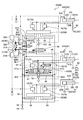
- FIG. 3 is a diagram illustrating an example of a hydraulic system according to the present embodiment.
- FIG. 4 is a functional block diagram illustrating an example of a control device according to the present embodiment.
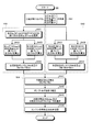
- FIG. 5 is a flowchart illustrating an example of processing performed by the merged state pump output calculation unit, the diversion state pump output calculation unit, and the surplus output calculation unit according to the present embodiment.
- FIG. 6 is a flowchart illustrating an example of processing by the target output calculation unit according to the present embodiment.
- FIG. 7 is a flowchart illustrating an example of processing by the reduced output calculation unit according to the present embodiment.
- FIG. 8 is a flowchart illustrating an example of processing by the target rotation speed calculation unit, the lower limit rotation speed setting unit, and the filter processing unit according to the present embodiment.
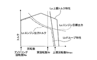
- FIG. 9 is a diagram illustrating an example of a torque diagram of the engine according to the present embodiment.
- FIG. 10 is a diagram illustrating an example of a matching state of the engine and the hydraulic pump according to the present embodiment.
- FIG. 11 is a diagram illustrating an example of a matching state of the engine and the hydraulic pump according to the present embodiment.
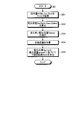
- FIG. 12 is a flowchart illustrating an example of a method for controlling the work machine according to the present embodiment.
- FIG. 13 is a diagram showing an example of fourth correlation data indicating the relationship between the set value of the throttle dial and the upper limit engine speed according to the present embodiment.
- FIG. 14 is a diagram illustrating an example of fifth correlation data indicating the relationship between the work mode according to the present embodiment and the maximum output of the engine.
- FIG. 15 is a diagram illustrating an example of third correlation data according to the present embodiment.
- FIG. 1 is a perspective view illustrating an example of a work machine 1 according to the present embodiment.
- the work machine 1 is a hybrid hydraulic excavator.
- the work machine 1 is appropriately referred to as a hydraulic excavator 1.
- the excavator 1 is driven by a work machine 10, an upper swing body 2 that supports the work machine 10, a lower traveling body 3 that supports the upper swing body 2, an engine 4, and the engine 4.
- the engine 4 is a power source of the excavator 1.
- the engine 4 has an output shaft 4 ⁇ / b> S connected to the generator motor 27 and the hydraulic pump 30.
- the engine 4 is, for example, a diesel engine.
- the engine 4 is accommodated in the machine room 7 of the upper swing body 2.
- the generator motor 27 is connected to the output shaft 4S of the engine 4 and generates power by the operation of the engine 4.
- the generator motor 27 is, for example, a switched reluctance motor.
- the generator motor 27 may be a PM (Permanent Magnet) motor.
- the hydraulic pump 30 is connected to the output shaft 4S of the engine 4 and discharges hydraulic oil by the operation of the engine 4.
- the hydraulic pump 30 includes a first hydraulic pump 31 connected to the output shaft 4S and driven by the engine 4, and a second hydraulic pump 32 connected to the output shaft 4S and driven by the engine 4. Including.
- the hydraulic pump 30 is accommodated in the machine room 7 of the upper swing body 2.
- the hydraulic cylinder 20 is operated by hydraulic oil supplied from the hydraulic pump 30.
- the hydraulic cylinder 20 is a hydraulic actuator that generates power for operating the work machine 10.
- the work machine 10 can be operated by the power generated by the hydraulic cylinder 20.
- the hydraulic cylinder 20 includes a bucket cylinder 21 that operates the bucket 11, an arm cylinder 22 that operates the arm 12, and a boom cylinder 23 that operates the boom 13.
- the electric motor 25 is operated by electric power supplied from the generator motor 27.
- the electric motor 25 is an electric actuator that generates power for turning the upper swing body 2.
- the upper-part turning body 2 can turn around the turning axis RX by the power generated by the electric motor 25.
- the hydraulic motor 24 is operated by hydraulic oil supplied from the hydraulic pump 30.
- the hydraulic motor 24 is a hydraulic actuator that generates power for causing the lower traveling body 3 to travel.
- the crawler belt 8 of the lower traveling body 3 can be rotated by the power generated by the hydraulic motor 24.
- the operating device 5 is disposed in the cab 6.
- the operating device 5 includes an operating member that is operated by a driver of the excavator 1.
- the operation member includes an operation lever or a joystick. When the operation device 5 is operated, the work machine 10 operates.
- FIG. 2 is a diagram schematically illustrating an example of the control system 1000 according to the present embodiment.
- the control system 1000 is mounted on the excavator 1 and controls the excavator 1.
- Control system 1000 includes a control device 100, a hydraulic system 1000A, and an electric system 1000B.
- the hydraulic system 1000 ⁇ / b> A includes a hydraulic pump 30, a hydraulic circuit 40 through which hydraulic oil discharged from the hydraulic pump 30 flows, a hydraulic cylinder 20 that operates with hydraulic oil supplied from the hydraulic pump 30 via the hydraulic circuit 40, and hydraulic pressure And a hydraulic motor 24 that is operated by hydraulic oil supplied from the hydraulic pump 30 via the circuit 40.
- the output shaft 4S of the engine 4 is connected to the hydraulic pump 30.
- the hydraulic pump 30 When the engine 4 is driven, the hydraulic pump 30 is operated.
- the hydraulic cylinder 20 and the hydraulic motor 24 operate based on the hydraulic oil discharged from the hydraulic pump 30.
- An engine speed sensor 4 ⁇ / b> R that detects the speed [rpm] of the engine 4 is provided in the engine 4.
- the hydraulic pump 30 is a variable displacement hydraulic pump.
- the hydraulic pump 30 is a swash plate hydraulic pump.
- the swash plate 30A of the hydraulic pump 30 is driven by a servo mechanism 30B.
- the capacity [cc / rev] of the hydraulic pump 30 is adjusted by adjusting the angle of the swash plate 30A by the servo mechanism 30B.
- the capacity of the hydraulic pump 30 refers to the discharge amount [cc / rev] of hydraulic oil discharged from the hydraulic pump 30 when the output shaft 4S of the engine 4 connected to the hydraulic pump 30 makes one rotation.
- the swash plate 30A of the hydraulic pump 30 includes a swash plate 31A of the first hydraulic pump 31 and a swash plate 32A of the second hydraulic pump 32.
- the servo mechanism 30B includes a servo mechanism 31B that adjusts the angle of the swash plate 31A of the first hydraulic pump 31, and a servo mechanism 32B that adjusts the angle of the swash plate 32A of the second hydraulic pump 32.
- the electric system 1000B includes a generator motor 27, a capacitor 14, a transformer 14C, a first inverter 15G, a second inverter 15R, and an electric motor 25 that is operated by electric power supplied from the generator motor 27.
- the output shaft 4S of the engine 4 is connected to the generator motor 27.
- the generator motor 27 When the engine 4 is driven, the generator motor 27 is activated.
- the rotor of the generator motor 27 rotates.
- the generator motor 27 When the rotor of the generator motor 27 rotates, the generator motor 27 generates power.
- the generator motor 27 may be connected to the output shaft 4S of the engine 4 through a power transmission mechanism such as PTO (Power Take Off).
- the electric motor 25 operates based on the electric power output from the generator motor 27.
- the electric motor 25 generates power for turning the upper swing body 2.
- a rotation sensor 16 is provided in the electric motor 25.
- the rotation sensor 16 includes, for example, a resolver or a rotary encoder. The rotation sensor 16 detects the rotation angle or rotation speed of the electric motor 25.
- the electric motor 25 generates regenerative energy during deceleration.
- the capacitor 14 includes, for example, an electric double layer capacitor and is charged by regenerative energy generated by the electric motor 25.
- the battery 14 may be a secondary battery such as a nickel metal hydride battery or a lithium ion battery.
- the driver's cab 6 is provided with an operating device 5, a throttle dial 33, and a work mode selector 34 that are operated by the driver.
- the operating device 5 includes an operating member that operates the lower traveling body 3, an operating member that operates the upper swing body 2, and an operating member that operates the work machine 10.
- the hydraulic motor 24 that travels the lower traveling body 3 operates based on the operation of the operation device 5.
- the electric motor 25 that rotates the upper swing body 2 operates based on the operation of the operation device 5.
- the hydraulic cylinder 20 that operates the work machine 10 operates based on the operation of the operation device 5.
- the operation device 5 includes a right operation lever 5R disposed on the right side of the driver seated on the driver's seat 6S and a left operation lever 5L disposed on the left side.
- the boom 13 is lowered or raised.
- the bucket 11 performs excavation operation or dump operation.
- the arm 12 performs a dumping operation or an excavating operation.
- the left operation lever 5L is operated in the left-right direction
- the upper swing body 2 turns left or right.
- the left operating lever 5L is operated in the front-rear direction
- the upper swing body 2 turns right or left, and when the left operating lever 5L is operated left and right, the arm 12 performs a dumping operation or excavating operation. Also good.
- the control system 1000 includes an operation amount sensor 90 that detects an operation amount of the operation device 5.
- the operation amount sensor 90 drives a bucket operation amount sensor 91 that detects an operation amount of the operation device 5 that is operated to drive the bucket cylinder 21 that operates the bucket 11 and an arm cylinder 22 that operates the arm 12.
- An arm operation amount sensor 92 that detects the operation amount of the operation device 5 that is operated to the boom 13 and a boom operation amount sensor 93 that detects the operation amount of the operation device 5 that is operated to drive the boom cylinder 23 that operates the boom 13. Including.
- the throttle dial 33 is an operation member for setting the fuel injection amount injected into the engine 4.
- the throttle dial 33 sets the upper limit rotational speed Nmax [rpm] of the engine 4.
- the work mode selector 34 is an operation member for setting the output characteristics of the engine 4.
- the maximum output [kW] of the engine 4 is set by the work mode selector 34.
- the control device 100 includes a computer system.
- the control device 100 includes an arithmetic processing device including a processor such as a CPU (Central Processing Unit), a storage device including a memory such as a ROM (Read Only Memory) or a RAM (Random Access Memory), an input / output interface device, Have
- the control device 100 outputs a command signal for controlling the hydraulic system 1000A and the electric system 1000B.
- the control device 100 includes a pump controller 100A that controls the hydraulic system 1000A, a hybrid controller 100B that controls the electric system 1000B, and an engine controller 100C that controls the engine 4.
- the pump controller 100A Based on at least one of the command signal transmitted from the hybrid controller 100B, the command signal transmitted from the engine controller 100C, and the detection signal transmitted from the operation amount sensor 90, the pump controller 100A A command signal for controlling the second hydraulic pump 32 is output.
- the pump controller 100A outputs a command signal for adjusting the capacity [cc / rev] of the hydraulic pump 30.
- the pump controller 100A adjusts the capacity [cc / rev] of the hydraulic pump 30 by outputting a command signal to the servo mechanism 30B and controlling the angle of the swash plate 30A of the hydraulic pump 30.
- the hydraulic pump 30 includes a swash plate angle sensor 30S that detects the angle of the swash plate 30A.
- the detection signal of the swash plate angle sensor 30S is output to the pump controller 100A.
- the pump controller 100A controls the angle of the swash plate 30A by outputting a command signal to the servo mechanism 30B based on the detection signal of the swash plate angle sensor 30S.
- the hydraulic pump 30 is driven by the engine 4.
- the operation per unit time discharged from the hydraulic pump 30 is increased by increasing the rotation speed [rpm] of the engine 4 and increasing the rotation speed per unit time of the output shaft 4S of the engine 4 connected to the hydraulic pump 30.
- the oil discharge flow rate Q [l / min] increases.
- the operation per unit time discharged from the hydraulic pump 30 is reduced when the rotation speed [rpm] of the engine 4 is decreased and the rotation speed per unit time of the output shaft 4S of the engine 4 connected to the hydraulic pump 30 is decreased.
- the oil discharge flow rate Q [l / min] decreases.
- the pump controller 100A outputs a command signal for adjusting each of the capacity [cc / rev] of the first hydraulic pump 31 and the capacity [cc / rev] of the second hydraulic pump 32.
- the pump controller 100A outputs a command signal to the servo mechanism 31B based on the detection signal of the swash plate angle sensor 31S, and controls the angle of the swash plate 31A of the first hydraulic pump 31 to thereby control the first hydraulic pump 31. Adjust the capacity [cc / rev].
- the pump controller 100A outputs a command signal to the servo mechanism 32B based on the detection signal of the swash plate angle sensor 32S, and controls the angle of the swash plate 32A of the second hydraulic pump 32, whereby the second hydraulic pump 32 Adjust the capacity [cc / rev].
- the hydraulic oil discharge flow rate Q [l / min] discharged from the hydraulic pump 30 is discharged from the second hydraulic pump 32 and the hydraulic oil discharge flow rate Q1 [l / min] discharged from the first hydraulic pump 31. Hydraulic fluid discharge flow rate Q2 [l / min]. As the rotational speed of the engine 4 increases and the rotational speed per unit time of the output shaft 4S of the engine 4 connected to the first hydraulic pump 31 and the second hydraulic pump 32 increases, the discharge of the first hydraulic pump 31 The flow rate Q1 [l / min] and the discharge flow rate Q2 [l / min] of the second hydraulic pump 32 increase.
- the maximum discharge flow rate Qmax [l / min] of the hydraulic pump 30 includes the maximum discharge flow rate Q1max [l / min] of the first hydraulic pump 31 and the maximum discharge flow rate Q2max [l / min] of the second hydraulic pump 32. .
- the first hydraulic pump 31 discharges hydraulic oil at the maximum discharge flow rate Q1max.
- the second hydraulic pump 32 discharges hydraulic oil at the maximum discharge flow rate Q2max.
- the maximum discharge flow rate Q1max and the maximum discharge flow rate Q2max are equal.
- the hybrid controller 100B controls the electric motor 25 based on the detection signal of the rotation sensor 16.
- the electric motor 25 operates based on the electric power supplied from the generator motor 27 or the battery 14.
- the hybrid controller 100B performs control of power transfer between the transformer 14C and the first inverter 15G and the second inverter 15R, and control of power transfer between the transformer 14C and the capacitor 14. To do.
- the hybrid controller 100B also generates the generator motor 27 and the electric motor 25 based on the detection signals of the temperature sensors provided in the generator motor 27, the electric motor 25, the battery 14, the first inverter 15G, and the second inverter 15R. The respective temperatures of the battery 14, the first inverter 15G, and the second inverter 15R are adjusted.
- the hybrid controller 100 ⁇ / b> B performs charge / discharge control of the battery 14, power generation control of the generator motor 27, and assist control of the engine 4 by the generator motor 27.
- the engine controller 100C generates a command signal based on the set value of the throttle dial 33, and outputs the command signal to the common rail control unit 29 provided in the engine 4.
- the common rail control unit 29 adjusts the fuel injection amount for the engine 4 based on the command signal transmitted from the engine controller 100C.
- FIG. 3 is a diagram illustrating an example of a hydraulic system 1000A according to the present embodiment.
- the hydraulic system 1000A is supplied with a hydraulic pump 30 that discharges hydraulic oil, a hydraulic circuit 40 through which hydraulic oil discharged from the hydraulic pump 30 flows, and hydraulic oil discharged from the hydraulic pump 30 via the hydraulic circuit 40.
- a hydraulic cylinder 20, a main operation valve 60 that adjusts the direction of hydraulic oil supplied to the hydraulic cylinder 20 and the hydraulic oil distribution flow rate Qa, and a pressure compensation valve 70 are provided.
- the hydraulic pump 30 includes a first hydraulic pump 31 and a second hydraulic pump 32.
- the hydraulic cylinder 20 includes a bucket cylinder 21, an arm cylinder 22, and a boom cylinder 23.
- the main operation valve 60 is supplied from the hydraulic pump 30 to the arm cylinder 22 and the first main operation valve 61 that adjusts the direction of the hydraulic oil supplied from the hydraulic pump 30 to the bucket cylinder 21 and the hydraulic oil distribution flow rate Qabk.
- a second main operation valve 62 that adjusts the direction of hydraulic oil and the hydraulic oil distribution flow rate Qaar, and a third main valve that adjusts the direction of hydraulic oil supplied from the hydraulic pump 30 to the boom cylinder 23 and the hydraulic oil distribution flow rate Qabm.
- an operation valve 63 is a slide spool type directional control valve.
- the pressure compensation valve 70 includes a pressure compensation valve 71, a pressure compensation valve 72, a pressure compensation valve 73, a pressure compensation valve 74, a pressure compensation valve 75, and a pressure compensation valve 76.
- the hydraulic system 1000A is provided in a merging channel 55 that connects the first hydraulic pump 31 and the second hydraulic pump 32, and includes a merging state in which the merging channel 55 is opened and a shunting state in which the merging channel 55 is closed.
- the hydraulic circuit 40 includes a first hydraulic pump passage 41 connected to the first hydraulic pump 31 and a second hydraulic pump passage 42 connected to the second hydraulic pump 32.
- the hydraulic circuit 40 includes a first supply channel 43 and a second supply channel 44 connected to the first hydraulic pump channel 41, a third supply channel 45 and a second supply channel 45 connected to the second hydraulic pump channel 42. 4 supply flow path 46.
- the first hydraulic pump flow path 41 is branched into a first supply flow path 43 and a second supply flow path 44 at the first branch portion Br1.
- the second hydraulic pump flow path 42 is branched into a third supply flow path 45 and a fourth supply flow path 46 at the fourth branch portion Br4.
- the hydraulic circuit 40 includes a first branch channel 47 and a second branch channel 48 connected to the first supply channel 43, and a third branch channel 49 and a fourth branch connected to the second supply channel 44. And a flow path 50.
- the first supply channel 43 is branched into a first branch channel 47 and a second branch channel 48 at the second branch portion Br2.
- the second supply channel 44 is branched into a third branch channel 49 and a fourth branch channel 50 at the third branch part Br3.
- the hydraulic circuit 40 includes a fifth branch channel 51 connected to the third supply channel 45 and a sixth branch channel 52 connected to the fourth supply channel 46.
- the first main operation valve 61 is connected to the first branch channel 47 and the third branch channel 49.
- the second main operation valve 62 is connected to the second branch channel 48 and the fourth branch channel 50.
- the third main operation valve 63 is connected to the fifth branch channel 51 and the sixth branch channel 52.
- the hydraulic circuit 40 connects the first bucket flow path 21A that connects the first main operation valve 61 and the cap-side space 21C of the bucket cylinder 21, and the first main operation valve 61 and the rod-side space 21L of the bucket cylinder 21. Second bucket flow path 21B.
- the hydraulic circuit 40 connects the first arm flow path 22A that connects the second main operation valve 62 and the rod side space 22L of the arm cylinder 22, and the second main operation valve 62 and the cap side space 22C of the arm cylinder 22. Second arm channel 22B.
- the hydraulic circuit 40 connects the first boom flow path 23A that connects the third main operation valve 63 and the cap side space 23C of the boom cylinder 23, and the third main operation valve 63 and the rod side space 23L of the boom cylinder 23. Second boom channel 23B.
- the cap side space of the hydraulic cylinder 20 is a space between the cylinder head cover and the piston.
- the rod side space of the hydraulic cylinder 20 is a space in which the piston rod is disposed.
- the hydraulic oil is supplied to the cap side space 21C of the bucket cylinder 21 and the bucket cylinder 21 extends, whereby the bucket 11 performs excavation.
- the hydraulic oil is supplied to the rod-side space 21L of the bucket cylinder 21, and the bucket 11 performs a dumping operation when the bucket cylinder 21 is retracted.
- the working oil is supplied to the cap-side space 22C of the arm cylinder 22 and the arm 12 extends, so that the arm 12 performs an excavation operation.
- the arm 12 performs a dumping operation.
- the first main operation valve 61 supplies hydraulic oil to the bucket cylinder 21 and collects the hydraulic oil discharged from the bucket cylinder 21.
- the spool of the first main operation valve 61 stops the supply of hydraulic oil to the bucket cylinder 21 to stop the bucket cylinder 21, and the first branch flow so that the hydraulic oil is supplied to the cap side space 21C.
- the second position PT2 that connects the path 21B and retracts the bucket cylinder 21 is movable.
- the first main operation valve 61 is operated so that the bucket cylinder 21 is at least one of a stopped state, an extended state, and a retracted state.
- the second main operation valve 62 supplies hydraulic oil to the arm cylinder 22 and collects the hydraulic oil discharged from the arm cylinder 22.
- the second main operation valve 62 has the same structure as the first main operation valve 61.
- the spool of the second main operation valve 62 has a stop position where the supply of hydraulic oil to the arm cylinder 22 is stopped to stop the arm cylinder 22, and a fourth branch flow path so that the hydraulic oil is supplied to the cap side space 22C. 50 and the second arm channel 22B are connected to each other to extend the arm cylinder 22, and the second branch channel 48 and the first arm channel 22A are supplied to the rod side space 22L.
- the second main operation valve 62 is operated so that the arm cylinder 22 is in at least one of a stopped state, an extended state, and a retracted state.
- the third main operation valve 63 supplies hydraulic oil to the boom cylinder 23 and collects the hydraulic oil discharged from the boom cylinder 23.
- the third main operation valve 63 has a structure equivalent to that of the first main operation valve 61.
- the spool of the third main operation valve 63 has a stop position where the supply of hydraulic oil to the boom cylinder 23 is stopped to stop the boom cylinder 23, and a fifth branch flow path so that the hydraulic oil is supplied to the cap side space 23C.
- 51 and the first boom passage 23A are connected to each other to extend the boom cylinder 23, and the sixth branch passage 52 and the second boom passage 23B are supplied to the rod-side space 23L.
- the third main operation valve 63 is operated so that the boom cylinder 23 is in at least one of a stopped state, an extended state, and a retracted state.
- the first main operation valve 61 is operated by the operation device 5.
- a pilot pressure determined based on the operation amount of the operation device 5 acts on the first main operation valve 61.
- the direction of the hydraulic oil supplied from the first main operation valve 61 to the bucket cylinder 21 and the distribution flow Qabk of the hydraulic oil are determined.
- the rod of the bucket cylinder 21 moves in a moving direction corresponding to the direction of the supplied hydraulic oil, and operates at a cylinder speed corresponding to the distributed flow rate Qabk of the supplied hydraulic oil.
- the bucket 11 is operated based on the moving direction of the bucket cylinder 21 and the cylinder speed.
- the second main operation valve 62 is operated by the operation device 5.
- a pilot pressure determined based on the operation amount of the operation device 5 acts on the second main operation valve 62.
- the direction of the hydraulic oil supplied from the second main operation valve 62 to the arm cylinder 22 and the distribution flow rate Qaar of the hydraulic oil are determined.
- the rod of the arm cylinder 22 moves in a movement direction corresponding to the direction of the supplied hydraulic oil, and operates at a cylinder speed corresponding to the distributed flow rate Qaar of the supplied hydraulic oil.
- the arm 12 operates based on the moving direction of the arm cylinder 22 and the cylinder speed.
- the third main operation valve 63 is operated by the operation device 5.
- a pilot pressure determined based on the operation amount of the operation device 5 acts on the third main operation valve 63.
- the direction of the hydraulic oil supplied from the third main operation valve 63 to the boom cylinder 23 and the distribution flow Qabm of the hydraulic oil are determined.
- the rod of the boom cylinder 23 moves in a moving direction corresponding to the direction of the supplied hydraulic oil, and operates at a cylinder speed corresponding to the distributed flow rate Qabm of the supplied hydraulic oil.
- the boom 13 is operated based on the moving direction of the boom cylinder 23 and the cylinder speed.
- the hydraulic oil discharged from each of the bucket cylinder 21, the arm cylinder 22, and the boom cylinder 23 is collected in the tank 54 via the discharge passage 53.
- the first hydraulic pump flow path 41 and the second hydraulic pump flow path 42 are connected by a merging flow path 55.
- the merge channel 55 is a channel that connects the first hydraulic pump 31 and the second hydraulic pump 32.
- the merge channel 55 connects the first hydraulic pump 31 and the second hydraulic pump 32 via the first hydraulic pump channel 41 and the second hydraulic pump channel 42.
- the first joining / dividing valve 67 is an opening / closing device that opens and closes the joining flow path 55.
- the first merging / dividing valve 67 opens and closes the merging channel 55 to switch between a merging state where the merging channel 55 is opened and a merging state where the merging channel 55 is closed.
- the first joining / dividing valve 67 is a switching valve. As long as the merge channel 55 can be opened and closed, the switching device that opens and closes the merge channel 55 may not be a switching valve.
- the spool of the first merging / dividing valve 67 opens the merging passage 55 and connects the first hydraulic pump passage 41 and the second hydraulic pump passage 42, and the merging passage 55 is closed to close the first hydraulic pressure. It is possible to move between the diversion positions separating the pump flow path 41 and the second hydraulic pump flow path 42.
- the control device 100 controls the first merging / dividing valve 67 so that the first hydraulic pump flow path 41 and the second hydraulic pump flow path 42 are in either the merging state or the diversion state.
- the merging state means that the merging channel 55 that connects the first hydraulic pump channel 41 and the second hydraulic pump channel 42 is opened in the first merging / dividing valve 67, thereby 2 hydraulic pump flow path 42 is connected via a merging flow path 55, and the hydraulic oil discharged from the first hydraulic pump flow path 41 and the hydraulic oil discharged from the second hydraulic pump flow path 42 are in the first combination.
- the diversion state means that the merging channel 55 connecting the first hydraulic pump channel 41 and the second hydraulic pump channel 42 is closed by the first merging / dividing valve 67, so The second hydraulic pump flow path 42 is separated, and the hydraulic oil discharged from the first hydraulic pump flow path 41 and the hydraulic oil discharged from the second hydraulic pump flow path 42 are separated.
- the hydraulic oil discharged from the first hydraulic pump 31 is supplied to the bucket cylinder 21 and the arm cylinder 22, and the hydraulic oil discharged from the second hydraulic pump 32 is supplied to the boom cylinder 23.
- the first hydraulic actuator supplied with the hydraulic oil discharged from the first hydraulic pump 31 in the diversion state is the bucket cylinder 21 and the arm cylinder 22.
- the second hydraulic actuator supplied with the hydraulic oil discharged from the second hydraulic pump 32 in the diversion state is the boom cylinder 23.
- the hydraulic oil discharged from the first hydraulic pump 31 is not supplied to the boom cylinder 23.
- the hydraulic oil discharged from the second hydraulic pump 32 is not supplied to the bucket cylinder 21 and the arm cylinder 22.
- the hydraulic oil discharged from each of the first hydraulic pump 31 and the second hydraulic pump 32 flows through the first hydraulic pump channel 41, the second hydraulic pump channel 42, the first main operation valve 61, After passing through each of the two main operation valves 62 and the third main operation valve 63, it is supplied to each of the bucket cylinder 21, the arm cylinder 22, and the boom cylinder 23.
- the hydraulic oil discharged from the first hydraulic pump 31 passes through each of the first hydraulic pump flow path 41, the first main operation valve 61, and the second main operation valve 62, and then the bucket cylinder 21. And supplied to the arm cylinder 22. Further, in the diversion state, the hydraulic oil discharged from the second hydraulic pump 32 is supplied to the boom cylinder 23 after passing through the second hydraulic pump flow path 42 and the third main operation valve 63.
- the hydraulic system 1000 ⁇ / b> A is provided between the shuttle valve 701 provided between the first main operation valve 61 and the second main operation valve 62, and between the second combined flow valve 68 and the third main operation valve 63. And a shuttle valve 702.
- the hydraulic system 1000 ⁇ / b> A includes a shuttle valve 701 and a second combined / dividing valve 68 connected to the shuttle valve 702.
- the second combined / dividing valve 68 has a maximum load sensing pressure (LS pressure) obtained by reducing the operating oil supplied to each of the bucket cylinder 21, the arm cylinder 22, and the boom cylinder 23 by the shuttle valve 701 and the shuttle valve 702. Select.
- the load sensing pressure is a pilot pressure used for pressure compensation.
- the maximum LS pressure is selected from the bucket cylinder 21 to the boom cylinder 23, and the pressure compensation valve 70 and the first hydraulic pump 31 of each of the bucket cylinder 21 to the boom cylinder 23 are selected.
- the servo mechanism 31B and the servo mechanism 32B of the second hydraulic pump 32 are supplied.
- the maximum LS pressure between the bucket cylinder 21 and the arm cylinder 22 is supplied to the pressure compensation valve 70 of the bucket cylinder 21 and the arm cylinder 22 and the servo mechanism 31B of the first hydraulic pump 31. Then, the LS pressure of the boom cylinder 23 is supplied to the pressure compensation valve 70 of the boom cylinder 23 and the servo mechanism 32B of the second hydraulic pump 32.
- the shuttle valve 701 and the shuttle valve 702 select a pilot pressure indicating the maximum value from among the pilot pressures output from the first main operation valve 61, the second main operation valve 62, and the third main operation valve 63.
- the selected pilot pressure is supplied to the pressure compensation valve 70 and the servo mechanisms (31B, 32B) of the hydraulic pump 30 (31, 32).
- the hydraulic system 1000 ⁇ / b> A includes a load pressure sensor 80 that detects the pressure PL of the hydraulic oil in the hydraulic cylinder 20.
- the hydraulic oil pressure PL in the hydraulic cylinder 20 is a load pressure of the hydraulic oil supplied to the hydraulic cylinder 20.
- a detection signal of the load pressure sensor 80 is output to the control device 100.
- the load pressure sensor 80 includes a bucket load pressure sensor 81 that detects the hydraulic oil pressure PLbk of the bucket cylinder 21, an arm load pressure sensor 82 that detects the hydraulic oil pressure PLar of the arm cylinder 22, and a boom. And a boom load pressure sensor 83 that detects the pressure PLbm of the hydraulic oil in the cylinder 23.
- the bucket load pressure sensor 81 is provided in the first bucket flow path 21A, and is provided in the bucket load pressure sensor 81C that detects the hydraulic oil pressure PLbkc in the cap side space 21C of the bucket cylinder 21 and the second bucket flow path 21B. And a bucket load pressure sensor 81L for detecting the pressure PLbkl of the hydraulic oil in the rod side space 21L of the bucket cylinder 21.
- the arm load pressure sensor 82 is provided in the second arm flow path 22B, and is provided in the first arm flow path 22A and the arm load pressure sensor 82C that detects the pressure PLArc of the hydraulic oil in the cap side space 22C of the arm cylinder 22. , And an arm load pressure sensor 82L for detecting the hydraulic pressure PParl in the rod side space 22L of the arm cylinder 22.
- the boom load pressure sensor 83 is provided in the first boom flow path 23A, and is provided in the boom load pressure sensor 83C that detects the hydraulic oil pressure PLbmc in the cap side space 23C of the boom cylinder 23, and the second boom flow path 23B. And a boom load pressure sensor 83L for detecting the pressure PLbml of the hydraulic oil in the rod side space 23L of the boom cylinder 23.
- the hydraulic system 1000A includes a discharge pressure sensor 800 that detects the discharge pressure P of the hydraulic oil discharged from the hydraulic pump 30.
- a detection signal of the discharge pressure sensor 800 is output to the control device 100.
- the discharge pressure sensor 800 is provided between the first hydraulic pump 31 and the first hydraulic pump flow path 41, and detects a discharge pressure sensor 801 that detects the discharge pressure P1 of the hydraulic oil discharged from the first hydraulic pump 31.
- a discharge pressure sensor 802 that is provided between the second hydraulic pump 32 and the second hydraulic pump flow path 42 and detects the discharge pressure P2 of the hydraulic oil discharged from the second hydraulic pump 32 is included.
- the pressure compensation valve 70 has a selection port for selecting communication, throttling, and blocking.
- the pressure compensation valve 70 includes a throttle valve that enables switching between cutoff, throttle, and communication with self-pressure.
- the pressure compensation valve 70 is intended to compensate the flow distribution according to the ratio of the metering opening area of each main operation valve 60 even when the load pressure of each hydraulic cylinder 20 is different.
- the pressure compensating valve 70 has a low load pressure hydraulic pressure so that the outlet pressure of the main operating valve 60 of the hydraulic cylinder 20 with low load pressure is equal to the outlet pressure of the main operating valve 60 of the hydraulic cylinder 20 with maximum load pressure.
- the pressure compensation valve 70 includes a pressure compensation valve 71 and a pressure compensation valve 72 connected to the first main operation valve 61, a pressure compensation valve 73 and a pressure compensation valve 74 connected to the second main operation valve 62, a third A pressure compensation valve 75 and a pressure compensation valve 76 connected to the main operation valve 63 are included.
- the pressure compensation valve 71 has a differential pressure across the first main operation valve 61 in a state in which the first branch flow path 47 and the first bucket flow path 21A are connected so that hydraulic oil is supplied to the cap-side space 21C. Compensate metering differential pressure).
- the pressure compensation valve 72 has a differential pressure across the first main operation valve 61 in a state in which the third branch flow path 49 and the second bucket flow path 21B are connected so that hydraulic oil is supplied to the rod side space 21L. Compensate metering differential pressure).
- the pressure compensation valve 73 has a differential pressure across the second main operation valve 62 in a state where the second branch flow path 48 and the first arm flow path 22A are connected so that hydraulic oil is supplied to the rod side space 22L. Compensate metering differential pressure).
- the pressure compensation valve 74 has a differential pressure across the second main operation valve 62 in a state where the fourth branch flow path 50 and the second arm flow path 22B are connected so that hydraulic oil is supplied to the cap side space 22C. Compensate metering differential pressure).
- the differential pressure across the main operation valve 60 (metering differential pressure) is the pressure between the inlet port corresponding to the hydraulic pump 30 side of the main operation valve 60 and the pressure of the outlet port corresponding to the hydraulic cylinder 20 side.
- the difference is the pressure difference for metering the flow rate.
- each of the bucket cylinder 21 and the arm cylinder 22 is provided.
- the hydraulic oil can be distributed at a flow rate corresponding to the operation amount of the operation device 5.
- the pressure compensation valve 70 can supply a flow rate based on the operation regardless of the loads of the plurality of hydraulic cylinders 20. For example, when a high load is applied to the bucket cylinder 21 and a light load is applied to the arm cylinder 22, the pressure compensation valve 70 (73, 74) disposed on the light load side is changed from the first main operation valve 61 to the bucket cylinder.
- the hydraulic oil is supplied from the second main operation valve 62 to the arm cylinder 22 regardless of the metering differential pressure ⁇ P1 generated when the hydraulic oil is supplied to the engine 21, the flow rate based on the operation amount of the second main operation valve 62 is increased.
- the metering differential pressure ⁇ P2 on the arm cylinder 22 side which is the light load side, is compensated so that the metering differential pressure ⁇ P1 on the bucket cylinder 21 side becomes substantially the same pressure.
- the pressure compensation valve 70 (71, 72) disposed on the light load side is moved from the second main operation valve 62 to the arm cylinder 22.
- a flow rate based on the operation amount of the first main operation valve 61 is supplied.
- the hydraulic circuit 40 has an unload valve 69.
- the hydraulic pump 30 discharges hydraulic oil at a flow rate corresponding to the minimum capacity.
- the hydraulic oil discharged from the hydraulic pump 30 when the hydraulic cylinder 20 is not driven is discharged (unloaded) through the unload valve 69.
- FIG. 4 is a functional block diagram illustrating an example of the control device 100 according to the present embodiment.
- the control device 100 includes a computer system.
- the control device 100 includes an arithmetic processing device 101, a storage device 102, and an input / output interface device 103.
- the control device 100 is connected to the first combined / divided valve 67 and the second combined / divided valve 68 and outputs a command signal to the first combined / divided valve 67 and the second combined / divided valve 68.
- the control device 100 also includes a load pressure sensor 80 that detects the pressure PL of the hydraulic cylinder 20, a discharge pressure sensor 800 that detects the discharge pressure P of hydraulic oil discharged from the hydraulic pump 30, and the operation amount S of the operation device 5. Is connected to each of the operation amount sensors 90 for detecting.
- the operation amount sensor 90 (91, 92, 93) is a pressure sensor.
- the pilot pressure acting on the first main operating valve 61 changes based on the operation amount Sbk of the operating device 5.
- the pilot pressure acting on the second main operating valve 62 changes based on the operation amount Sar of the operating device 5.
- the pilot pressure acting on the third main operating valve 63 changes based on the operation amount Sbm of the operating device 5.
- the bucket operation amount sensor 91 detects a pilot pressure that acts on the first main operation valve 61 when the operation device 5 is operated to drive the bucket cylinder 21.
- the arm operation amount sensor 92 detects a pilot pressure that acts on the second main operation valve 62 when the operation device 5 is operated to drive the arm cylinder 22.
- the boom operation amount sensor 93 detects a pilot pressure that acts on the third main operation valve 63 when the operation device 5 is operated to drive the boom cylinder 23.
- the arithmetic processing unit 101 includes a distribution flow rate calculation unit 112, a switching device control unit 114, a pump flow rate calculation unit 116, a combined state pump output calculation unit 118, a diversion state pump output calculation unit 120, and a surplus output calculation unit 122.
- the storage device 102 includes a storage unit 141 that stores first correlation data, a storage unit 142 that stores second correlation data, a storage unit 143 that stores third correlation data, and a storage unit that stores fourth correlation data. 144, a storage unit 145 that stores the fifth correlation data, and a storage unit 146 that stores various other data.
- the distribution flow rate calculation unit 112 has a plurality of hydraulic oil pressures PL based on the hydraulic pressures PL of the hydraulic cylinders 20 and an operation amount S of the operating device 5 operated to drive the hydraulic cylinders 20.
- the distribution flow rate Qa of the hydraulic oil supplied to each of the hydraulic cylinders 20 is calculated.
- the distribution flow rate calculation unit 112 is based on the hydraulic oil pressure PL of the hydraulic cylinder 20, the operation amount S of the operating device 5, and the hydraulic oil discharge pressure P discharged from the hydraulic pump 30.
- the distribution flow rate Qa is calculated.
- the pressure PL of the hydraulic oil in the hydraulic cylinder 20 is detected by a load pressure sensor 80.
- the distribution flow rate calculation unit 112 acquires the hydraulic oil pressure PLbk of the bucket cylinder 21 from the bucket load pressure sensor 81, acquires the hydraulic oil pressure PLar of the arm cylinder 22 from the arm load pressure sensor 82, and the boom load pressure sensor 83. From the hydraulic oil pressure PLbm of the boom cylinder 23.
- the operation amount S of the operation device 5 is detected by the operation amount sensor 90.
- the distribution flow rate calculation unit 112 acquires the operation amount Sbk of the operation device 5 operated to drive the bucket cylinder 21 from the bucket operation amount sensor 91 and operates to drive the arm cylinder 22 from the arm operation amount sensor 92.
- the operation amount Sar of the operation device 5 to be operated is acquired, and the operation amount Sbm of the operation device 5 operated to drive the boom cylinder 23 is acquired from the boom operation amount sensor 93.
- the discharge pressure P of the hydraulic oil of the hydraulic pump 30 is detected by a discharge pressure sensor 800.
- the distribution flow rate calculation unit 112 acquires the discharge pressure P1 of the hydraulic oil of the first hydraulic pump 31 from the discharge pressure sensor 801, and acquires the discharge pressure P2 of the hydraulic oil of the second hydraulic pump 32 from the discharge pressure sensor 802.
- the distribution flow rate calculation unit 112 includes the hydraulic pressure PL (PLbk, PLar, PLbm) of each of the plurality of hydraulic cylinders 20 (21, 22, 23) and each of the plurality of hydraulic cylinders 20 (21, 22, 23). Based on the operation amount S (Sbk, Sar, Sbm) of the operating device 5 operated to drive the engine, the distribution flow rate of the hydraulic oil supplied to each of the plurality of hydraulic cylinders 20 (21, 22, 23) Qa (Qabk, Qaar, Qabm) is calculated.
- the distribution flow rate calculation unit 112 calculates the distribution flow rate Qa based on the equation (1).
- Qd is a required flow rate of hydraulic oil in the hydraulic cylinder 20.
- P is a discharge pressure of hydraulic oil discharged from the hydraulic pump 30.
- PL is the load pressure of the hydraulic oil in the hydraulic cylinder 20.
- ⁇ PC is a set differential pressure between the inlet side and the outlet side of the main operation valve 60. In the present embodiment, the differential pressure between the inlet side and the outlet side of the main operation valve 60 is set to the set differential pressure ⁇ PC.
- the set differential pressure ⁇ PC is set in advance for each of the first main operation valve 61, the second main operation valve 62, and the third main operation valve 63, and is stored in the storage unit 146.
- the distribution flow rate Qabk of the bucket cylinder 21, the distribution flow rate Qaar of the arm cylinder 22, and the distribution flow rate Qabm of the boom cylinder 23 are calculated based on the equations (2), (3), and (4), respectively.
- Qabk Qdbk ⁇ ⁇ ⁇ (P ⁇ PLbk) / ⁇ PC ⁇ (2)
- Qaar Qdar ⁇ ⁇ ⁇ (P-PLar) / ⁇ PC ⁇ (3)
- Qabm Qdbm ⁇ ⁇ ⁇ (P ⁇ PLbm) / ⁇ PC ⁇ (4)
- Qdbk is a required flow rate of the hydraulic oil in the bucket cylinder 21.
- PLbk is the pressure of the hydraulic oil in the bucket cylinder 21.
- Qdar is a required flow rate of the hydraulic oil in the arm cylinder 22.
- PLar is the pressure of the hydraulic oil in the arm cylinder 22.
- Qdbm is the required flow rate of the hydraulic oil for the boom cylinder 23.
- PLbm is the load pressure of the hydraulic oil in the boom cylinder 23.
- the set differential pressure ⁇ PC between the inlet side and the outlet side of 63 is the same value.
- the required flow rate Qd (Qdbk, Qdar, Qdbm) is calculated based on the operation amount S (Sbk, Sar, Sbm) of the controller device 5.
- the required flow rate Qd (Qdbk, Qdar, Qdbm) is calculated based on the pilot pressure detected by the operation amount sensor 90 (91, 92, 93).
- the operation amount S (Sbk, Sar, Sbm) of the operation device 5 and the pilot pressure detected by the operation amount sensor 90 (91, 92, 93) correspond one-to-one.
- the distribution flow rate calculation unit 112 converts the pilot pressure detected by the operation amount sensor 90 into the spool stroke of the main operation valve 60, and calculates the required flow rate Qd based on the spool stroke.
- the first correlation data indicating the relationship between the pilot pressure and the spool stroke of the main operation valve 60 and the second correlation data indicating the relationship between the spool stroke of the main operation valve 60 and the required flow rate Qd are known data, and are stored in the storage unit. 141 and the storage unit 142.
- Each of the first correlation data indicating the relationship between the pilot pressure and the spool stroke of the main operation valve 60 and the second correlation data indicating the relationship between the spool stroke of the main operation valve 60 and the required flow rate Qd includes conversion table data. .
- the distributed flow rate calculation unit 112 acquires a detection signal of the bucket operation amount sensor 91 that detects the pilot pressure acting on the first main operation valve 61.
- the distribution flow rate calculation unit 112 converts the pilot pressure acting on the first main operation valve 61 into the spool stroke of the first main operation valve 61 using the first correlation data stored in the storage unit 141. Thereby, the spool stroke of the first main operation valve 61 is calculated based on the detection signal of the bucket operation amount sensor 91 and the first correlation data stored in the storage unit 141.
- the distribution flow rate calculation unit 112 converts the calculated spool stroke of the first main operation valve 61 into the required flow rate Qdbk of the bucket cylinder 21 using the second correlation data stored in the storage unit 142. Thereby, the distribution flow rate calculation unit 112 can calculate the required flow rate Qdbk of the bucket cylinder 21.
- the distribution flow rate calculation unit 112 acquires a detection signal of the arm operation amount sensor 92 that detects the pilot pressure acting on the second main operation valve 62.
- the distribution flow rate calculation unit 112 converts the pilot pressure acting on the second main operation valve 62 into the spool stroke of the second main operation valve 62 using the first correlation data stored in the storage unit 141.
- the spool stroke of the second main operation valve 62 is calculated based on the detection signal of the arm operation amount sensor 92 and the first correlation data stored in the storage unit 141.
- the distribution flow rate calculation unit 112 converts the calculated spool stroke of the second main operation valve 62 into the required flow rate Qdar of the arm cylinder 22 by using the second correlation data stored in the storage unit 142. Thereby, the distribution flow rate calculation unit 112 can calculate the required flow rate Qdar of the arm cylinder 22.
- the distribution flow rate calculation unit 112 acquires a detection signal of the boom operation amount sensor 93 that detects the pilot pressure acting on the third main operation valve 63.
- the distribution flow rate calculation unit 112 converts the pilot pressure acting on the third main operation valve 63 into the spool stroke of the third main operation valve 63 using the first correlation data stored in the storage unit 141.
- the spool stroke of the third main operation valve 63 is calculated based on the detection signal of the boom operation amount sensor 93 and the first correlation data stored in the storage unit 141.
- the distribution flow rate calculation unit 112 converts the calculated spool stroke of the third main operation valve 63 into the required flow rate Qdbm of the boom cylinder 23 using the second correlation data stored in the storage unit 142. Thereby, the distribution flow rate calculation unit 112 can calculate the required flow rate Qdbm of the boom cylinder 23.
- the bucket load pressure sensor 81 includes the bucket load pressure sensor 81C and the bucket load pressure sensor 81L, and the pressure PLbk of the hydraulic oil in the bucket cylinder 21 operates in the cap side space 21C of the bucket cylinder 21. Oil pressure PLbkc and hydraulic oil pressure PLbkl in rod side space 21L of bucket cylinder 21 are included.
- the distribution flow rate calculation unit 112 selects either the pressure PLbkc or the pressure PLbkl based on the moving direction of the spool of the first main operation valve 61.
- the distribution flow rate calculation unit 112 uses the pressure PLbkc detected by the bucket load pressure sensor 81C and distributes the flow rate based on the equation (2). Qabk is calculated.
- the distribution flow rate calculation unit 112 uses the pressure PLbkl detected by the bucket load pressure sensor 81L (2 ) To calculate the distribution flow rate Qabk.
- the arm load pressure sensor 82 includes an arm load pressure sensor 82C and an arm load pressure sensor 82L.
- the hydraulic oil pressure PLar of the arm cylinder 22 is the hydraulic oil pressure PLArc in the cap side space 22C of the arm cylinder 22.
- the distribution flow rate calculation unit 112 uses the pressure PLArc detected by the arm load pressure sensor 82C, based on the expression (3). Qaar is calculated.
- the distribution flow rate calculation unit 112 uses (3) the pressure Parallel detected by the arm load pressure sensor 82L. ) To calculate the distribution flow rate Qaar.
- the boom load pressure sensor 83 includes a boom load pressure sensor 83C and a boom load pressure sensor 83L
- the hydraulic oil pressure PLbm of the boom cylinder 23 is the hydraulic oil pressure PLbmc of the cap side space 23C of the boom cylinder 23.
- the distribution flow rate calculation unit 112 uses the pressure PLbmc detected by the boom load pressure sensor 83C, based on the expression (4). Qabm is calculated.
- the distribution flow rate calculation unit 112 uses the pressure PLbml detected by the boom load pressure sensor 83L (4 ) To calculate the distribution flow rate Qabm.
- the discharge pressure P of the hydraulic oil discharged from the hydraulic pump 30 is detected by the discharge pressure sensor 800.
- the distribution flow rate calculation unit 112 repeats numerical values so that the equation (5) converges. Calculation may be carried out to calculate the distribution flow rates Qabk, Qaar, Qabm.
- Qlp is the pump limit flow rate.
- the pump limit flow rate Qlp corresponds to the maximum discharge flow rate Qmax of the hydraulic pump 30, the target discharge flow rate Qt1 of the first hydraulic pump 31 determined based on the target output of the first hydraulic pump 31, and the target output of the second hydraulic pump 32. This is the smallest value among the target discharge flow rates Qt2 of the second hydraulic pump 32 determined based on the values.
- the operation device 5 includes a pilot pressure type operation lever, and a pressure sensor is used as the operation amount sensor 90 (91, 92, 93).
- the operation device 5 may include an electric operation lever.
- a straw sensor capable of detecting a lever stroke indicating a stroke of the operation lever is used as the operation amount sensor (91, 92, 93).
- the distribution flow rate calculation unit 112 can convert the lever stroke detected by the operation amount sensor 90 into the spool stroke of the main operation valve 60 and calculate the required flow rate Qd based on the spool stroke.
- the distribution flow rate calculation unit 112 can convert a lever stroke into a spool stroke using a predetermined conversion table.
- the opening / closing device control unit 114 Based on the comparison result between the distribution flow rate Qa calculated by the distribution flow rate calculation unit 112 and the threshold value Qs, the opening / closing device control unit 114 sets the first combination / divergence valve 67 so as to be in either the merge state or the diversion state.
- the command signal to control is output.
- the threshold value Qs is a threshold value for the distribution flow rate Qa of the hydraulic cylinder 20.
- the opening / closing device control unit 114 When the distribution flow rate Qa calculated by the distribution flow rate calculation unit 112 is equal to or less than the threshold value Qs, the opening / closing device control unit 114 outputs a command signal to the first combined / dividing valve 67 so as to be in a diversion state.
- the opening / closing device control unit 114 outputs a command signal to the first merging / dividing valve 67 so as to be in the merging state.
- the threshold value Qs is the maximum discharge flow rate Qmax of hydraulic fluid that can be discharged from each of the first hydraulic pump 31 and the second hydraulic pump 32. That is, in the present embodiment, the opening / closing device control unit 114 controls the first combined / divided valve 67 based on the comparison result between the distributed flow rate Qa and the maximum discharge flow rate Qmax. When the distributed flow rate Qa is equal to or less than the maximum discharge flow rate Qmax, the opening / closing device control unit 114 outputs a command signal to the first combined / dividing valve 67 so as to be in a diversion state. When the distributed flow rate Qa is larger than the maximum discharge flow rate Qmax, the opening / closing device control unit 114 outputs a command signal to the first joining / dividing valve 67 so as to be in a joining state.
- the sum of the distribution flow rate Qabk of the hydraulic oil supplied to the bucket cylinder 21 and the distribution flow rate Qaar of the hydraulic oil supplied to the arm cylinder 22 is equal to or less than the maximum discharge flow rate Q1max of the first hydraulic pump 31;
- the opening / closing device control unit 114 commands the first joint / divergence valve 67 to be in a diversion state. Output a signal.
- the opening / closing device control unit 114 When the sum of the distribution flow rate Qabk of the hydraulic oil supplied to the bucket cylinder 21 and the distribution flow rate Qaar of the hydraulic oil supplied to the arm cylinder 22 is larger than the maximum discharge flow rate Q1max of the first hydraulic pump 31, or the boom cylinder 23 When the distribution flow rate Qabm of the hydraulic oil supplied to is larger than the maximum discharge flow rate Q2max of the second hydraulic pump 32, the opening / closing device control unit 114 outputs a command signal to the first merging / dividing valve 67 so as to be in a merging state. To do.
- the pump flow rate calculation unit 116 is discharged from the hydraulic oil discharge flow rate Q1 and the second hydraulic pump 32 discharged from the first hydraulic pump 31 in the diversion state based on the distribution flow rate Qa calculated by the distribution flow rate calculation unit 112.
- Each of the hydraulic oil discharge flow rate Q2 is calculated.
- the pump flow rate calculation unit 116 detects the capacity [cc / rev] of the hydraulic pump 30 (31, 32) calculated from the detection value of the swash plate angle sensor 30S (31S, 32S) and the engine speed sensor 4R.
- the discharge flow rates Q1 and Q2 can be calculated based on the rotational speed of the engine 4 to be performed.
- the combined state pump output calculation unit 118 indicates the output Wa1 of the first hydraulic pump 31 and the output Wa2 of the second hydraulic pump 32 that are required in the combined state based on the distributed flow rate Qa calculated by the distributed flow rate calculation unit 112.
- a combined pump output Wa is calculated.
- the diversion state pump output calculation unit 120 indicates the output Wb1 of the first hydraulic pump 31 and the output Wb2 of the second hydraulic pump 32 required in the diversion state based on the distribution flow rate Qa calculated by the distribution flow rate calculation unit 112.
- the diversion state pump output Wb is calculated.
- the surplus output calculation unit 122 calculates the surplus output Ws of the engine 4 based on the combined state pump output Wa and the diverted state pump output Wb.
- the combined state pump output calculation unit 118 is the higher of the discharge pressure P1 of the hydraulic oil discharged from the first hydraulic pump 31 and the discharge pressure P2 of the hydraulic oil discharged from the second hydraulic pump 32 in the diversion state. Based on Pmax, the discharge flow rate Q1 of the hydraulic oil discharged from the first hydraulic pump 31 in the diversion state, and the discharge flow rate Q2 of the hydraulic oil discharged from the second hydraulic pump 32 in the diversion state, the combined state pump output Wa is calculated.
- the diversion state pump output calculation unit 120 is discharged from the second hydraulic pump 32 in the diversion state and the discharge pressure P1 and the discharge flow rate Q1 of the hydraulic oil discharged from the first hydraulic pump 31 in the diversion state. Based on the hydraulic oil discharge pressure P2 and the discharge flow rate Q2, the diversion state pump output Wb is calculated.
- FIG. 5 is a flowchart illustrating an example of a process SA performed by the merge state pump output calculation unit 118, the diversion state pump output calculation unit 120, and the surplus output calculation unit 122 according to the present embodiment.
- the process of step SA2 (SA21, SA22, SA23, SA24) is a process by the merged state pump output calculation unit 118
- the process of step SA3 (SA31, SA32, SA33) is the divided state pump output.
- It is a process by the calculation unit 120
- the process of step SA4 (SA41, SA42, SA43, SA44) is a process by the surplus output calculation unit 122.
- the process shown in FIG. 5 is a process in a diversion state.
- the opening / closing device control unit 114 puts the hydraulic circuit 40 into a diversion state.
- the control device 100 obtains the discharge pressure P1 of the first hydraulic pump 31, the discharge pressure P2 of the second hydraulic pump 32, the discharge flow rate Q1 of the first hydraulic pump 31, and the discharge flow rate Q2 of the second hydraulic pump 32 in the shunt state. (Step SA1).
- the discharge flow rate Q1 and the discharge flow rate Q2 are calculated by the pump flow rate calculation unit 116.
- the discharge pressure P1 and the discharge pressure P2 are acquired by the discharge pressure sensor 800 (801, 802).
- the merging state pump output calculation unit 118 calculates the output Wa of the hydraulic pump 30 in the merging state assuming that the hydraulic circuit 40 is in the merging state.
- the combined state pump output calculation unit 118 is the higher of the discharge pressure P1 of the hydraulic oil discharged from the first hydraulic pump 31 and the discharge pressure P2 of the hydraulic oil discharged from the second hydraulic pump 32 in the diversion state.
- Pmax is selected (step SA21). In the present embodiment, the discharge pressure Pmax is the discharge pressure P1.
- the combined state pump output calculation unit 118 assumes that the hydraulic circuit 40 is in the combined state based on the discharge pressure Pmax and the discharge flow rate Q1 of the hydraulic oil discharged from the first hydraulic pump 31 in the divided state.
- the required output Wa1 of the first hydraulic pump 31 is calculated (step SA22).
- the output Wa1 is calculated based on the product of the discharge pressure Pmax (P1) and the discharge flow rate Q1.
- the combined state pump output calculation unit 118 assumes that the hydraulic circuit 40 is in the combined state based on the discharge pressure Pmax and the discharge flow rate Q2 of the hydraulic oil discharged from the second hydraulic pump 32 in the divided state.
- the required output Wa2 of the second hydraulic pump 32 is calculated (step SA23).
- the output Wa2 is calculated based on the product of the discharge pressure Pmax (P1) and the discharge flow rate Q2.
- the combined state pump output calculating unit 118 calculates the combined state pump output Wa required when the hydraulic circuit 40 is assumed to be in the combined state (step SA24).
- the hydraulic circuit 40 is in a diversion state, and the diversion state pump output calculation unit 120 calculates the output Wb of the hydraulic pump 30 in the diversion state.
- the diversion state pump output calculation unit 120 is based on the discharge pressure P1 of the hydraulic oil discharged from the first hydraulic pump 31 in the diversion state and the discharge flow rate Q1 of the hydraulic oil discharged from the first hydraulic pump 31 in the diversion state.
- the output Wb1 of the first hydraulic pump 31 required when the hydraulic circuit 40 is in the diversion state is calculated (step SA31).
- the output Wb1 is calculated based on the product of the discharge pressure P1 and the discharge flow rate Q1.
- the diversion state pump output calculation unit 120 is based on the discharge pressure P2 of the hydraulic oil discharged from the second hydraulic pump 32 in the diversion state and the discharge flow rate Q2 of the hydraulic oil discharged from the second hydraulic pump 32 in the diversion state.
- the output Wb2 of the second hydraulic pump 32 required when the hydraulic circuit 40 is in the diversion state is calculated (step SA32).
- the output Wb2 is calculated based on the product of the discharge pressure P2 and the discharge flow rate Q2.
- the diversion state pump output calculation unit 120 calculates the diversion state pump output Wb when the hydraulic circuit 40 is in the diversion state (step SA33).
- the surplus output calculation unit 122 is based on the combined state pump output Wa calculated by the combined state pump output calculation unit 118 and the divided state pump output Wb calculated by the divided state pump output calculation unit 120.
- the output Ws is calculated (step SA41).
- the pressure of the hydraulic oil flowing through the hydraulic circuit 40 is higher than the discharge pressure Pmax of the first hydraulic pump 31 and the discharge pressure P2 of the second hydraulic pump 32. Become. Therefore, the output Wa of the hydraulic pump 30 when it is assumed that the hydraulic circuit 40 is in the merging state is calculated based on the discharge pressure Pmax.
- the pressure of the hydraulic oil flowing through the hydraulic circuit 40 is separated into the discharge pressure P1 of the first hydraulic pump 31 and the discharge pressure P2 of the second hydraulic pump 32. Therefore, the output Wb of the hydraulic pump 30 when the hydraulic circuit 40 is in the shunt state is calculated based on each of the discharge pressure P1 and the discharge pressure P2. Further, the combined state pump output Wa calculated based on the discharge pressure Pmax is larger than the divided state pump output Wb calculated based on each of the discharge pressure P1 and the discharge pressure P2. Therefore, the surplus output Ws becomes a positive value.
- the surplus output calculation unit 122 corrects the surplus output Ws calculated in step SA41 with the pump torque efficiency (step SA42).
- the upper limit surplus output Wsmax indicating the upper limit value of the surplus output Ws is set in advance and stored in the storage unit 146.
- the surplus output calculation unit 122 selects the smaller one of the upper limit surplus output Wsmax stored in the storage unit 146 and the surplus output Ws calculated in step SA41 (step SA43).
- the surplus output calculation unit 122 determines one of the upper limit surplus output Wsmax and the surplus output Ws selected in Step SA43 as the final surplus output Ws (Step SA44).
- the target output calculation unit 124 operates the operation amount S of the operating device 5, the discharge pressure P ⁇ b> 1 of hydraulic oil discharged from the first hydraulic pump 31, and the discharge of hydraulic oil discharged from the second hydraulic pump 32.
- a target output Wr of the engine 4 is calculated based on the pressure P2.
- the target output Wr of the engine 4 is the target output of the engine 4 required for driving the work machine 10 and the target output of the engine 4 required for driving the fan that cools the engine 4. Calculated based on the sum.
- FIG. 6 is a flowchart showing an example of processing SB by the target output calculation unit 124 according to the present embodiment.
- the process shown in FIG. 6 is a process in a diversion state.
- the control device 100 acquires the operation amount S of the operating device 5 in the diversion state, the discharge pressure P1 of the first hydraulic pump 31, and the discharge pressure P2 of the second hydraulic pump 32 (step SB1).
- the operation amount S of the operation device 5 is acquired by the operation amount sensor 90 (91, 92, 93).
- the discharge pressure P1 and the discharge pressure P2 are acquired by the discharge pressure sensor 800 (801, 802).
- control device 100 also acquires the setting value of the throttle dial 33 and the work mode selected by the work mode selector 34.
- the target output calculation unit 124 includes an operation amount S of the operating device 5, a discharge pressure P1 of the first hydraulic pump 31, a discharge pressure P2 of the second hydraulic pump 32, a set value of the throttle dial 33, and a work mode selector.
- the target output of the engine 4 necessary for driving the work machine 10 is calculated based on the work mode selected by 34 (step SB2).
- the target output calculation unit 124 calculates the target output of the engine 4 necessary for driving the fan that cools the engine 4 (step SB3).
- the target output calculation unit 124 calculates the target output of the electric motor 25 (step SB4).
- the target output calculation unit 124 adds the target output of the engine 4 necessary for driving the work machine 10 calculated in step SB2 and the target output of the engine 4 required for driving the fan calculated in step SB3. Is calculated.
- the target output calculation unit 124 also calculates the electric motor calculated in step SB4 from the sum of the target output of the engine 4 required for driving the work machine 10 and the target output of the engine 4 required for driving the fan.
- the target output of 25 is reduced (step SB5). That is, in the present embodiment, the hydraulic excavator 1 is a hybrid hydraulic excavator, and the output of the electric motor 25 is supplemented to the output of the engine 4. Therefore, the target output of the engine 4 can be reduced by the target output of the electric motor 25.
- the target output calculation unit 124 determines the target output of the engine 4 calculated in step SB5 as the final target output Wr of the engine 4 (step SB6).
- the reduced output calculation unit 126 corrects the target output Wr of the engine 4 calculated by the target output calculation unit 124 based on the surplus output Ws calculated by the surplus output calculation unit 122 to obtain the target output Wr.
- the reduced output Wc of the engine 4 that is further reduced is calculated.
- FIG. 7 is a flowchart showing an example of the process SC by the reduced output calculation unit 126 according to the present embodiment.
- the process shown in FIG. 7 is a process in a diversion state.
- the reduced output calculation unit 126 acquires the surplus output Ws of the engine 4 calculated by the surplus output calculation unit 122 (step SC1).
- the reduced output calculation unit 126 acquires the target output Wr of the engine 4 calculated by the target output calculation unit 124 (step SC2).
- the reduced output calculation unit 126 subtracts the surplus output Ws from the target output Wr of the engine 4 to determine a reduced output Wc that is the final target output of the engine 4 in the shunt state (step SC3).
- [Wc Wr ⁇ Ws].
- the target rotation speed calculation unit 128 is based on the target output of the engine 4 calculated by the target output calculation unit 124 and the third correlation data stored in the storage unit 143, and the engine 4 in the shunt state.
- a target rotational speed Nr is calculated.
- the third correlation data stored in the storage unit 143 is known data indicating the relationship between the output of the engine 4 and the rotational speed of the engine 4.
- the third correlation data indicating the relationship between the output of the engine 4 and the rotational speed of the engine 4 includes conversion table data.
- the lower limit rotational speed setting unit 130 is divided into the distribution flow rate Qabk, the distribution flow rate Qaar, and the distribution flow rate Qabm calculated by the distribution flow rate calculation unit 112 in each of the bucket cylinder 21, the arm cylinder 22, and the boom cylinder 23 in the diversion state.
- a lower limit rotational speed Nmin indicating a lower limit value of the rotational speed of the engine 4 is set so that the hydraulic oil is supplied.
- the opening / closing device control unit 114 determines whether or not to put the hydraulic circuit 40 in the diversion state based on the distribution flow rate Qa calculated by the distribution flow rate calculation unit 112.
- the rotational speed of the engine 4 that is equal to or higher than the lower limit rotational speed Nmin is the rotational speed of the engine 4 that can maintain the shunt state.
- hydraulic oil is supplied to each of the plurality of hydraulic cylinders 20 (21, 22, 23) at the distributed flow rate Qa calculated by the distributed flow rate calculation unit 112. Is supplied and the diversion state is maintained.
- the filter processing unit 132 filters the operation amount S of the operation device 5 when the operation speed of the operation device 5 is equal to or higher than a predetermined value in a diversion state.
- the operation speed of the operation device 5 refers to the amount of change in the operation amount of the operation device 5 per unit time.
- the operation amount S of the operation device 5 and the detection value (pressure value of the pilot pressure) of the operation amount sensor 90 correspond one-to-one.
- the operation speed of the controller device 5 is equivalent to the amount of change in the detected value of the operation amount sensor 90 per unit time.
- the filter processing unit 132 filters the detection value of the operation amount sensor 90 when the change rate of the detection value of the operation amount sensor 90 is equal to or higher than a predetermined value in the diversion state.
- the distribution flow rate calculation unit 112 supplies each of the bucket cylinder 21, the arm cylinder 22, and the boom cylinder 23 based on the operation amount S of the operation device 5 after being filtered by the filter processing unit 132.
- the distributed flow rate Qabk, the distributed flow rate Qaar, and the distributed flow rate Qabm are calculated.
- FIG. 8 is a flowchart showing an example of a process SD performed by the target rotation number calculation unit 128, the lower limit rotation number setting unit 130, and the filter processing unit 132 according to the present embodiment.
- the process shown in FIG. 8 is a process in a diversion state.
- the filter processing unit 132 filters the operation amount S (Sbk, Sar, Sbm) of the operation device 5 when the operation speed of the operation device 5 is equal to or higher than a specified value in the diversion state (step SD1).
- the filter process includes a first-order low-pass filter process.
- the filter processing unit 132 increases the time constant of the first-order local filter processing as the operation speed of the controller device 5 increases.
- the distribution flow rate calculation unit 112 is configured to supply hydraulic fluid supplied to each of the bucket cylinder 21, the arm cylinder 22, and the boom cylinder 23.
- the distributed flow rate Qabk, the distributed flow rate Qaar, and the distributed flow rate Qabm are calculated (step SD2).
- the lower limit rotation speed setting unit 130 selects the largest distributed flow rate Qamax among the distributed flow rate Qabk, the distributed flow rate Qaar, and the distributed flow rate Qabm calculated in step SD2 (step SD3).
- the most distributed flow rate Qamax is the distributed flow rate Qabk.
- the lower limit rotation speed setting unit 130 adds a preset surplus flow rate to the distribution flow rate Qamax (step SD4).
- Lower limit rotation speed setting unit 130 determines the sum of allocated flow rate Qamax and marginal flow rate selected in step SD3 as allocated flow rate Qamax.
- the lower limit rotational speed setting unit 130 calculates the lower limit rotational speed Nmin based on the distribution flow rate Qamax determined in step SD4 and the maximum capacity qmax [cc / rev] of the hydraulic pump 30 (step SD5).
- the engine control unit 134 outputs a command signal for controlling the engine 4 based on the reduction output Wc of the engine 4 calculated by the reduction output calculation unit 126 in the diversion state.
- the engine control unit 134 controls the engine 4 so as to drive at a rotational speed equal to or higher than the lower limit rotational speed Nmin calculated by the lower limit rotational speed setting unit 130.
- the engine control unit 134 compares the target rotational speed Nr of the engine 4 calculated by the target rotational speed calculation unit 128 with the lower limit rotational speed Nmin calculated by the lower limit rotational speed setting unit 130, and compares the target rotational speed Nr.
- the engine 4 is controlled so as to be driven at a higher rotational speed of the lower limit rotational speed Nmin.
- FIG. 9 is a diagram illustrating an example of a torque diagram of the engine 4 according to the present embodiment.
- the upper limit torque characteristic of the engine 4 is defined by the maximum output torque line La shown in FIG.
- the droop characteristic of the engine 4 is defined by the engine droop line Lb shown in FIG.
- the engine target output is defined by an equal output line Lc shown in FIG.
- the control device 100 controls the engine 4 based on the upper limit torque characteristic, the droop characteristic, and the engine target output.
- the control device 100 controls the engine 4 so that the rotation speed and torque of the engine 4 do not exceed the maximum output torque line La, the engine droop line Lb, and the equal output line Lc.
- control device 100 controls the engine 4 so that the rotation speed and torque of the engine 4 do not exceed the engine output torque line Lt defined by the maximum output torque line La, the engine droop line Lb, and the equal output line Lc.
- the command signal to control is output.
- the engine 4 is driven in a high load state where a large load is applied.
- the engine 4 is driven in a no-load state in which almost no load is applied.
- an upper limit rotational speed Nmax that is a target rotational speed of the engine 4 in the no-load state is set.
- the engine droop line Lb is set so as to pass through the upper limit rotational speed Nmax and have a predetermined slope determined in advance.
- the control device 100 outputs a command signal for changing the rotational speed of the engine 4 based on the operation amount S of the operation device 5 and the load applied to the work machine 10. For example, when the engine 4 in the idling state is rotating at the idling rotational speed Na and the transition is made from the no-load state to the loaded state, the rotational speed of the engine 4 increases from the idling rotational speed Na to the actual rotational speed Nr. The actual engine speed Nr of the engine 4 is controlled so as not to exceed the upper limit engine speed Nmax. Further, when the engine 4 is rotating at the actual rotation speed Nr, when the engine 4 is shifted from the load state to the no-load state, the rotation speed of the engine 4 rapidly increases, but is controlled so as not to exceed the upper limit rotation speed Nmax.
- the driver operates the throttle dial 33 to set the fuel injection amount for the engine 4.
- An upper limit speed Nmax of the engine 4 is set by the throttle dial 33.
- the control device 100 outputs a command signal for controlling the fuel injection amount based on the load fluctuation of the work implement 10 so that the actual engine speed Nr of the engine 4 does not exceed the upper limit engine speed Nmax set by the throttle dial 33. To do.
- 10 and 11 are diagrams showing an example of a matching state of the engine 4 and the hydraulic pump 30 according to the present embodiment.
- the absorption torque of the hydraulic pump 30 is set according to the absorption torque characteristic Lp that changes according to the actual rotational speed Nr of the engine 4. Further, the total torque characteristic of the hydraulic pump 30 in the diversion state is defined by the pump total torque line Lq as a total value of the distribution torque of the first hydraulic pump 31 and the distribution torque of the second hydraulic pump 32. The final absorption torque of the hydraulic pump 30 is set by the smaller value of the torques determined by Lp and Lq.
- a matching point M1 is defined at the intersection of the absorption torque characteristic Lp and the engine output torque line Lt.
- a matching point M2 is defined at the intersection of the pump total torque line Lq and the engine output torque line Lt.
- the rotational speed of the engine 4 shifts to the matching point with the smaller torque of the engine 4 out of the matching point M1 and the matching point M2.
- the rotational speed of the engine 4 is stabilized at the matching point M1.
- the torque of the engine 4 at the matching point M2 is smaller than the torque of the engine 4 at the matching point M1
- the rotational speed of the engine 4 is stabilized at the matching point M2.
- the hydraulic circuit 40 is switched between the merging state and the diversion state.
- the load acting on the bucket 11 or the arm 12 that is a work machine element provided on the distal end side of the work machine 10 is large.
- the load acting on the boom 13 that is a work machine element provided on the base end side of the work machine 10 is small.
- the discharge pressure P2 of the second hydraulic pump 32 can be lowered while the discharge pressure P1 of the first hydraulic pump 31 is increased by setting the hydraulic circuit 40 in a shunt state.
- a combined state pump output Wa indicating the output of the hydraulic pump 30 when the hydraulic circuit 40 is assumed to be in the combined state when the hydraulic circuit 40 is in the divided state is calculated.
- a diversion state pump output Wb indicating the output of the hydraulic pump 30 in the diversion state is calculated.
- the surplus output Ws of the engine 4 is calculated based on the combined pump output Wa and the split pump output Wb. Based on the surplus output Ws, a reduced output Wc of the engine 4 that is reduced from the target output Wr of the engine 4 is calculated.
- the engine 4 is controlled on the basis of the reduced output Wc when the hydraulic circuit 40 is in a diversion state. This suppresses the engine 4 from being driven at an unnecessarily high output.
- FIG. 12 is a flowchart showing an example of a control method of the excavator 1 according to the present embodiment.
- the control device 100 includes the operation amount S of the operating device 5 in the shunt state, the discharge pressure P1 of the first hydraulic pump 31, the discharge pressure P2 of the second hydraulic pump 32, the discharge flow rate Q1 of the first hydraulic pump 31, and the second hydraulic pump. 32, the discharge flow rate Q2, the set value of the throttle dial 33, and the work mode selected via the work mode selector 34 are acquired (step SP1).
- the upper limit engine speed Nmax of the engine 4 is set based on the set value of the throttle dial 33. Further, the maximum output of the engine 4 is set based on the work mode.
- FIG. 13 is a diagram showing an example of fourth correlation data indicating the relationship between the set value of the throttle dial 33 and the upper limit rotational speed Nmax of the engine 4 according to the present embodiment.
- the horizontal axis is the set value of the throttle dial 33
- the vertical axis is the upper limit rotational speed Nmax of the engine 4.
- the fourth correlation data is known data and is stored in the storage unit 144.
- the upper limit rotational speed Nmax of the engine 4 changes based on the set value of the throttle dial 33.
- the driver can adjust the upper limit rotation speed Nmax of the engine 4 by operating the throttle dial 33.
- FIG. 14 is a diagram illustrating an example of fifth correlation data indicating the relationship between the work mode according to the present embodiment and the maximum output of the engine 4.
- the horizontal axis represents the rotational speed of the engine 4 and the vertical axis represents the torque of the engine 4.
- the driver can operate the work mode selector 34 to select one of the first work mode (P mode) and the second work mode (E mode).
- the upper limit torque characteristic of the engine 4 indicated by the maximum output torque line La is changed.
- the upper limit torque characteristic of the engine 4 is defined by the maximum output torque line Lap.
- the upper limit torque characteristic of the engine 4 is defined by the maximum output torque line Lae.
- the maximum output of the engine 4 is changed by changing the upper limit torque characteristic of the engine 4.
- the fifth correlation data indicating the relationship between the work mode selected by the work mode selector 34 and the maximum output (maximum output torque) of the engine 4 is known data and is stored in the storage unit 145.
- the driver can adjust the maximum output of the engine 4 by operating the work mode selector 34.
- the filter processing unit 132 determines whether or not to filter the operation amount S of the controller device 5 (step SP2).
- the operation amount S of the operation device 5 when the operation speed of the operation device 5 is equal to or higher than a specified value, the operation amount S of the operation device 5 is filtered. When the operation speed of the controller device 5 is smaller than the specified value, the operation amount S of the controller device 5 is not filtered.
- the specified value is a predetermined value and is stored in the storage unit 146. That is, in the present embodiment, when the controller device 5 is operated at high speed, the operation amount S is filtered. When the controller device 5 is operated at a low speed, the operation amount S is not filtered.
- step SP2 If it is determined in step SP2 that the filter processing is to be performed (step SP2: Yes), the filter processing unit 132 filters the operation amount S of the controller device 5 (step SP3). In the present embodiment, the filter processing unit 132 performs first-order low-pass filter processing on the operation amount S. In addition, the filter processing unit 132 increases the time constant of the first-order low-pass filter process as the operation speed of the controller device 5 is higher.
- step SP2 determines whether the filtering process is not performed (step SP2: No)
- the filtering process of the operation amount S of the controller device 5 is not performed, and the process proceeds to the next step.
- the control device 100 determines the surplus output Ws of the engine 4 according to the processing SA described with reference to FIG. 5 (step SP4).
- control device 100 determines the target output Wr of the engine 4 according to the process SB described with reference to FIG. 6 (step SP5).
- control device 100 calculates the lower limit rotational speed Nmin of the engine 4 according to the process SD described with reference to FIG. 8 (step SP6).
- control device 100 calculates the reduced output Wc of the engine 4 according to the process SC described with reference to FIG. SP7).
- control device 100 Based on the reduced output Wc of engine 4 calculated in step SP7 and the third correlation data stored in storage unit 143, control device 100 calculates target rotational speed Nr of engine 4 in the shunt state (step). SP8).
- the control device 100 compares the target rotational speed Nr of the engine 4 calculated by the target rotational speed calculation unit 128 with the lower limit rotational speed Nmin calculated by the lower limit rotational speed setting unit 130, and compares the target rotational speed Nr and the lower limit rotational speed. The higher number of revolutions is selected from the number Nmin.
- the control device 100 determines a target matching rotational speed between the engine 4 and the hydraulic pump 30 based on the selected rotational speed (step SP9).
- FIG. 15 is a diagram showing an example of third correlation data according to the present embodiment.
- the horizontal axis represents the rotational speed of the engine 4 and the vertical axis represents the torque of the engine 4.
- the third correlation data is known data indicating the relationship between the output of the engine 4 and the rotational speed of the engine 4, and is stored in the storage unit 143.
- an equal output line Lc defines a reduced output Wc that is an engine target output according to the present embodiment. As the surplus output Ws increases, the reduced output Wc indicated by the equal output line Lc decreases as indicated by the arrow in FIG.
- the control device 100 Based on the reduced output Wc (equal output line Lc) calculated by the reduced output calculating unit 126 and the third correlation data stored in the storage unit 143, the control device 100 performs the engine 4 and the hydraulic pump in the shunt state. 30 target matching rotation speeds are determined. In the example shown in FIG. 15, the target matching rotation speed is determined based on the intersection of the iso-output line Lc and the line Ld indicating the third correlation data.
- the control device 100 controls the engine 4 to drive at a target matching rotational speed set between the upper limit rotational speed Nmax and the lower limit rotational speed Nmin (step SP10).
- the merging flow passage 55 that connects the first hydraulic pump 31 and the second hydraulic pump 32 is switched between the divergence state and the merging state by the first merging / dividing valve 67.
- the combined state pump output Wa indicating the output of the hydraulic pump 30 when the hydraulic circuit 40 is assumed to be in the combined state in the divided state
- the divided state pump output Wb indicating the output of the hydraulic pump 30 in the divided state.
- the surplus output Ws is calculated.
- the target output Wr is reduced based on the surplus output Ws, and a reduced output Wc that is a final target output is calculated.
- the engine 4 is driven based on the reduced output Wc, thereby suppressing the engine 4 from being driven at an unnecessarily high output. Therefore, the fuel consumption of the engine 4 is reduced.
- the engine 4 is driven with a necessary and sufficient output, and the work implement 10 can be smoothly operated while reducing the fuel consumption of the engine 4.
- the relationship [Wa ⁇ Pmax ⁇ Q1 + Pmax ⁇ Q2] is established among the combined pump output Wa, the discharge pressure Pmax, the discharge flow rate Q1, and the discharge flow rate Q2.
- the discharge pressure Pmax is the higher discharge pressure of the discharge pressure P1 and the discharge pressure P2.
- a relationship of [Wb ⁇ P1 ⁇ Q1 + P2 ⁇ Q2] is established among the shunt pump output Wb, the discharge pressure P1, the discharge pressure P2, the discharge flow rate Q1, and the discharge flow rate Q2. Accordingly, an appropriate surplus output Ws can be calculated based on the combined state pump output Wa and the divided state pump output Wb.
- a lower limit rotational speed Nmin of the engine 4 that can maintain the shunt state is set.
- the engine control unit 134 controls the engine 4 so as to drive at a rotational speed equal to or higher than the lower limit rotational speed Nmin.
- the operation amount S of the operation device 5 used for calculating the distribution flow rate Qa is filtered.
- the distribution flow rate Qa is calculated based on the operation amount S that changes rapidly when the operation speed of the controller device 5 is high, the surplus output Ws, the reduced output Wc calculated based on the distribution flow rate Qa, and The lower limit rotational speed Nmin and the like also change abruptly, and the smooth operation of the work machine 10 may be hindered.
- the operation amount S is filtered.
- the hydraulic pump 30 is a swash plate type hydraulic pump.
- the hydraulic pump 30 may not be a swash plate type hydraulic pump. Further, the hydraulic pump 30 may not be a variable displacement hydraulic pump but may be a fixed displacement hydraulic pump.
- the pressure PLbk, the pressure PLar, and the pressure PLbm are the pressure of the bucket cylinder 21, the pressure of the arm cylinder 22, and the pressure of the boom cylinder 23.
- the pressure of the bucket cylinder 21, the pressure of the arm cylinder 22, and the pressure of the boom cylinder 23 corrected by the area ratio of the throttle valve included in the pressure compensation valve 71 to the pressure compensation valve 76 are expressed as pressure PLbk, pressure PLar, And the pressure PLbm.
- the threshold value Qs used when determining whether or not to operate the first combined flow valve 67 is the maximum discharge flow rate Qmax.
- the threshold value Qs may be a value smaller than the maximum discharge flow rate Qmax.
- the work machine 1 is the hybrid hydraulic excavator 1.
- the work machine 1 may not be a hybrid hydraulic excavator 1.
- the upper swing body 2 is swung by the electric motor 25, but may be swung by a hydraulic motor.
- the hydraulic motor may include a turning motor in either the first hydraulic actuator or the second hydraulic actuator to calculate the distribution flow rate and the pump output.
- control system 1000 is applied to the excavator 1.
- the work machine to which the control system 1000 is applied is not limited to the hydraulic excavator 1, and can be widely applied to hydraulic-driven work machines other than the hydraulic excavator.
- SYMBOLS 1 Hydraulic excavator (work machine), 2 ... Upper turning body, 3 ... Lower traveling body, 4 ... Engine, 4R ... Engine speed sensor, 4S ... Output shaft, 5 ... Operation device, 5L ... Left operation lever, 5R ... Right control lever, 6 ... driver's cab, 6S ... driver's seat, 7 ... machine room, 8 ... crawler belt, 10 ... work machine, 11 ... bucket, 12 ... arm, 13 ... boom, 14 ... capacitor, 14C ... transformer, 15G ... 1st inverter, 15R ... 2nd inverter, 16 ... Rotation sensor, 20 ... Hydraulic cylinder, 21 ...
- Discharge flow path 54 ... Tank, 55 ... Merge flow path (flow path), 60 ... Main operation valve, 61 ... First Main operation valve, 62 ... second main operation valve, 63 ... third main operation valve, 67 ... first combined / divided valve, 68 ... second combined / divided valve, 69 ... unloading valve, 70 ... pressure compensation valve, 71 ... Pressure compensation valve, 72 ... Pressure compensation valve, 73 ... Pressure compensation valve, 74 ... Pressure compensation valve, 75 ... Pressure compensation valve, 76 ... Pressure compensation valve, 80 ... Load pressure sensor, 81 ... Bucket load pressure sensor, 81C ... Bucket Load pressure sensor, 81L ... Bucket load pressure sensor, 82 ...
- Arm load pressure sensor 82C ... Arm load pressure sensor, 82L ... Arm load pressure sensor, 83 ... Boom load pressure sensor, 83C ... Boom load pressure sensor, 83L ... Boom load Pressure sensor, 90 ... operation Production sensor 91 ... Bucket operation amount sensor 92 ... Arm operation amount sensor 93 ... Boom operation amount sensor 100 ... Control device 100A ... Pump controller 100B ... Hybrid controller 100C Engine controller 101 ... Arithmetic processing device DESCRIPTION OF SYMBOLS 102 ... Memory
- Divided state pump output calculation 122 ... surplus output calculation unit, 124 ... target output calculation unit, 126 ... reduction output calculation unit, 128 ... target rotation number calculation unit, 130 ... lower limit rotation number setting unit, 132 ... filter processing unit, 134 ... engine control unit 141 storage unit 142 storage unit 143 storage unit 144 storage unit 14 ... Storage unit, 146 ... Storage unit, 701 ... Shuttle valve, 702 ... Shuttle valve, 800 ... Discharge pressure sensor, 801 ... Discharge pressure sensor, 802 ... Discharge pressure sensor, 1000 ... Control system, 1000A ... Hydraulic system, 1000B ... Electric System, Br1 ... first branch, Br2 ... second branch, Br3 ... third branch, Br4 ... fourth branch, Q ...
Landscapes
- Engineering & Computer Science (AREA)
- General Engineering & Computer Science (AREA)
- Mining & Mineral Resources (AREA)
- Structural Engineering (AREA)
- Civil Engineering (AREA)
- Mechanical Engineering (AREA)
- Physics & Mathematics (AREA)
- Fluid Mechanics (AREA)
- Chemical & Material Sciences (AREA)
- Combustion & Propulsion (AREA)
- Operation Control Of Excavators (AREA)
- Fluid-Pressure Circuits (AREA)
- Control Of Vehicle Engines Or Engines For Specific Uses (AREA)
- Combined Controls Of Internal Combustion Engines (AREA)
Abstract
Description
図1は、本実施形態に係る作業機械1の一例を示す斜視図である。本実施形態においては、作業機械1がハイブリッド方式の油圧ショベルであることとする。以下の説明においては、作業機械1を適宜、油圧ショベル1、と称する。
図2は、本実施形態に係る制御システム1000の一例を模式的に示す図である。制御システム1000は、油圧ショベル1に搭載され、油圧ショベル1を制御する。制御システム1000は、制御装置100と、油圧システム1000Aと、電動システム1000Bとを含む。
図3は、本実施形態に係る油圧システム1000Aの一例を示す図である。油圧システム1000Aは、作動油を吐出する油圧ポンプ30と、油圧ポンプ30から吐出された作動油が流れる油圧回路40と、油圧回路40を介して油圧ポンプ30から吐出された作動油が供給される油圧シリンダ20と、油圧シリンダ20に供給される作動油の方向及び作動油の配分流量Qaを調整する主操作弁60と、圧力補償弁70とを備える。
油圧システム1000Aは、油圧シリンダ20の作動油の圧力PLを検出する負荷圧力センサ80を有する。油圧シリンダ20の作動油の圧力PLは、油圧シリンダ20に供給される作動油の負荷圧力である。負荷圧力センサ80の検出信号は、制御装置100に出力される。
圧力補償弁70は、連通と絞りと遮断とを選択するための選択ポートを有する。圧力補償弁70は、自己圧で遮断と、絞りと、連通との切り替えを可能とする、絞り弁を含む。圧力補償弁70は、各油圧シリンダ20の負荷圧が異なっていても、各主操作弁60のメータリング開口面積の比率に応じて流量分配を補償することを目的としている。圧力補償弁70がない場合、低負荷側の油圧シリンダ20にほとんどの作動油が流れてしまう。圧力補償弁70は、低負荷圧の油圧シリンダ20の主操作弁60の出口圧力が、最大負荷圧の油圧シリンダ20の主操作弁60の出口圧力と同等になるように、低負荷圧の油圧シリンダ20に圧力損失を作用させることで、各主操作弁60の出口圧力が同一となるため、流量分配の機能を実現する。
油圧回路40は、アンロード弁69を有する。油圧回路40においては、油圧シリンダ20を駆動しないときにおいても、油圧ポンプ30からは最小容量に相当する流量の作動油が吐出される。油圧シリンダ20を駆動しないときにおいて油圧ポンプ30から吐出された作動油は、アンロード弁69を介して排出(アンロード)される。
図4は、本実施形態に係る制御装置100の一例を示す機能ブロック図である。制御装置100は、コンピュータシステムを含む。制御装置100は、演算処理装置101と、記憶装置102と、入出力インターフェース装置103とを有する。
配分流量算出部112は、複数の油圧シリンダ20のそれぞれの作動油の圧力PLと、複数の油圧シリンダ20のそれぞれを駆動するために操作される操作装置5の操作量Sとに基づいて、複数の油圧シリンダ20のそれぞれに供給される作動油の配分流量Qaを算出する。本実施形態において、配分流量算出部112は、油圧シリンダ20の作動油の圧力PLと、操作装置5の操作量Sと、油圧ポンプ30から吐出される作動油の吐出圧力Pとに基づいて、配分流量Qaを算出する。
Qaar=Qdar×√{(P-PLar)/ΔPC}・・・(3)
Qabm=Qdbm×√{(P-PLbm)/ΔPC}・・・(4)
開閉装置制御部114は、配分流量算出部112で算出された配分流量Qaと閾値Qsとの比較結果に基づいて、合流状態又は分流状態のいずれか一方になるように第1合分流弁67を制御する指令信号を出力する。
ポンプ流量算出部116は、配分流量算出部112で算出された配分流量Qaに基づいて、分流状態において第1油圧ポンプ31から吐出される作動油の吐出流量Q1及び第2油圧ポンプ32から吐出される作動油の吐出流量Q2のそれぞれを算出する。本実施形態において、分流状態において第1油圧ポンプ31から吐出される作動油の吐出流量Q1は、バケットシリンダ21に供給される作動油の配分流量Qabkとアームシリンダ22に供給される作動油の配分流量Qaarとの和である(Q1=Qabk+Qaar)。分流状態において第2油圧ポンプ32から吐出される作動油の吐出流量Q2は、ブームシリンダ23に供給される作動油の配分流量Qabmである(Q2=Qabm)。
合流状態ポンプ出力算出部118は、配分流量算出部112で算出された配分流量Qaに基づいて、合流状態において要求される第1油圧ポンプ31の出力Wa1及び第2油圧ポンプ32の出力Wa2を示す合流状態ポンプ出力Waを算出する。本実施形態において、合流状態ポンプ出力Waは、合流状態において要求される第1油圧ポンプ31の出力Wa1と第2油圧ポンプ32の出力Wa2との和である(Wa=Wa1+Wa2)。
図4において、目標出力算出部124は、操作装置5の操作量Sと、第1油圧ポンプ31から吐出される作動油の吐出圧力P1と、第2油圧ポンプ32から吐出される作動油の吐出圧力P2とに基づいて、エンジン4の目標出力Wrを算出する。
図4において、低減出力算出部126は、余剰出力算出部122で算出された余剰出力Wsに基づいて、目標出力算出部124で算出されたエンジン4の目標出力Wrを補正して、目標出力Wrよりも低減されたエンジン4の低減出力Wcを算出する。
図4において、目標回転数算出部128は、目標出力算出部124で算出されたエンジン4の目標出力と記憶部143に記憶されている第3相関データとに基づいて、分流状態におけるエンジン4の目標回転数Nrを算出する。記憶部143に記憶されている第3相関データは、エンジン4の出力とエンジン4の回転数との関係を示す既知データである。エンジン4の出力とエンジン4の回転数との関係を示す第3相関データは、変換テーブルデータを含む。
図4において、エンジン制御部134は、分流状態において、低減出力算出部126で算出されたエンジン4の低減出力Wcに基づいて、エンジン4を制御する指令信号を出力する。本実施形態において、エンジン制御部134は、下限回転数設定部130で算出された下限回転数Nmin以上の回転数で駆動するように、エンジン4を制御する。また、エンジン制御部134は、目標回転数算出部128で算出されたエンジン4の目標回転数Nrと下限回転数設定部130で算出された下限回転数Nminとを比較して、目標回転数Nr及び下限回転数Nminのうち高い方の回転数で駆動するように、エンジン4を制御する。
図9は、本実施形態に係るエンジン4のトルク線図の一例を示す図である。エンジン4の上限トルク特性が、図9に示す最大出力トルク線Laによって規定される。エンジン4のドループ特性が、図9に示すエンジンドループ線Lbによって規定される。エンジン目標出力が、図9に示す等出力線Lcによって規定される。
上述のように、本実施形態においては、油圧回路40は合流状態と分流状態とに切り替えられる。作業機10の掘削動作において、作業機10の先端側に設けられる作業機要素であるバケット11又はアーム12に作用する負荷は大きい可能性が高い。一方、作業機10の掘削動作において、作業機10の基端側に設けられる作業機要素であるブーム13に作用する負荷は小さい可能性が高い。そのような場合、油圧回路40を分流状態にすることにより、第1油圧ポンプ31の吐出圧力P1を高くした状態で、第2油圧ポンプ32の吐出圧力P2を低くすることができる。
以上説明したように、本実施形態によれば、第1油圧ポンプ31と第2油圧ポンプ32とを接続する合流流路55が第1合分流弁67により分流状態と合流状態とに切り替えられる。油圧回路40が分流状態において、合流状態であると仮定したときの油圧ポンプ30の出力を示す合流状態ポンプ出力Waと分流状態のときの油圧ポンプ30の出力を示す分流状態ポンプ出力Wbとに基づいて余剰出力Wsが算出される。その余剰出力Wsに基づいて目標出力Wrが低減されて、最終的な目標出力である低減出力Wcが算出される。分流状態においては、低減出力Wcに基づいてエンジン4が駆動されることにより、エンジン4が不必要に高い出力で駆動されることが抑制される。したがって、エンジン4の燃費が低減される。
Claims (9)
- エンジンと、
前記エンジンによって駆動される第1油圧ポンプ及び第2油圧ポンプと、
前記第1油圧ポンプと前記第2油圧ポンプとを接続する流路に設けられ、前記流路が開けられる合流状態と前記流路が閉じられる分流状態とを切り替え可能な開閉装置と、
前記分流状態において前記第1油圧ポンプから吐出された作動油が供給される第1油圧アクチュエータと、
前記分流状態において前記第2油圧ポンプから吐出された作動油が供給される第2油圧アクチュエータと、
前記第1油圧アクチュエータ及び前記第2油圧アクチュエータのそれぞれの作動油の圧力と前記第1油圧アクチュエータ及び前記第2油圧アクチュエータのそれぞれを駆動するために操作される操作装置の操作量とに基づいて、前記第1油圧アクチュエータ及び前記第2油圧アクチュエータのそれぞれに供給される前記作動油の配分流量を算出する配分流量算出部と、
前記配分流量に基づいて、前記合流状態において要求される前記第1油圧ポンプの出力及び前記第2油圧ポンプの出力を示す合流状態ポンプ出力を算出する合流状態ポンプ出力算出部と、
前記配分流量に基づいて、前記分流状態において要求される前記第1油圧ポンプの出力及び前記第2油圧ポンプの出力を示す分流状態ポンプ出力を算出する分流状態ポンプ出力算出部と、
前記合流状態ポンプ出力と前記分流状態ポンプ出力とに基づいて、前記エンジンの余剰出力を算出する余剰出力算出部と、
前記余剰出力に基づいて前記エンジンの目標出力を補正して、前記目標出力よりも低減された前記エンジンの低減出力を算出する低減出力算出部と、
前記分流状態において、前記低減出力に基づいて前記エンジンを制御するエンジン制御部と、
を備える制御システム。 - 前記合流状態ポンプ出力は、前記合流状態において要求される前記第1油圧ポンプの出力と前記第2油圧ポンプの出力との和を含み、
前記分流状態ポンプ出力は、前記分流状態において要求される前記第1油圧ポンプの出力と前記第2油圧ポンプの出力との和を含み、
前記余剰出力は、前記合流状態ポンプ出力と前記分流状態ポンプ出力との差を含む、
請求項1に記載の制御システム。 - 前記配分流量に基づいて、前記分流状態において前記第1油圧ポンプから吐出される前記作動油の吐出流量及び前記第2油圧ポンプから吐出される前記作動油の吐出流量のそれぞれを算出するポンプ流量算出部を備え、
前記合流状態ポンプ出力算出部は、前記分流状態において前記第1油圧ポンプから吐出される前記作動油の吐出圧力及び前記第2油圧ポンプから吐出される前記作動油の吐出圧力のうち高い方の吐出圧力と、前記分流状態において前記第1油圧ポンプから吐出される前記作動油の吐出流量と、前記分流状態において前記第2油圧ポンプから吐出される前記作動油の吐出流量とに基づいて、前記合流状態ポンプ出力を算出し、
前記分流状態ポンプ出力算出部は、前記分流状態において前記第1油圧ポンプから吐出される前記作動油の吐出圧力及び吐出流量と、前記分流状態において前記第2油圧ポンプから吐出される前記作動油の吐出圧力及び吐出流量とに基づいて、前記分流状態ポンプ出力を算出する、
請求項1又は請求項2に記載の制御システム。 - 前記操作装置の操作量と前記第1油圧ポンプから吐出される前記作動油の吐出圧力と前記第2油圧ポンプから吐出される前記作動油の吐出圧力とに基づいて、前記エンジンの目標出力を算出する目標出力算出部を備える、
請求項1から請求項3のいずれか一項に記載の制御システム。 - 前記分流状態において前記第1油圧アクチュエータ及び前記第2油圧アクチュエータのそれぞれに前記配分流量で前記作動油が供給されるように、前記エンジンの回転数の下限値を示す下限回転数を設定する下限回転数設定部を備え、
前記エンジン制御部は、前記下限回転数以上の回転数で駆動するように前記エンジンを制御する、
請求項1から請求項4のいずれか一項に記載の制御システム。 - 前記配分流量と前記第1油圧ポンプ及び前記第2油圧ポンプのそれぞれが吐出可能な前記作動油の最大吐出流量との比較結果に基づいて、前記合流状態又は前記分流状態のいずれか一方になるように前記開閉装置を制御する開閉装置制御部を備え、
前記下限回転数以上の前記エンジンの回転数は、前記分流状態が維持される前記エンジンの回転数である、
請求項5に記載の制御システム。 - 前記エンジンの出力と前記エンジンの回転数との関係を示す相関データを記憶する記憶部と、
前記エンジンの目標出力と前記相関データとに基づいて、前記分流状態における前記エンジンの目標回転数を算出する目標回転数算出部と、を備え、
前記エンジン制御部は、前記目標回転数及び前記下限回転数のうち高い方の回転数で駆動するように前記エンジンを制御する、
請求項5又は請求項6に記載の制御システム。 - 前記分流状態において、前記操作装置の操作速度が規定値以上のときに前記操作装置の操作量をフィルタ処理するフィルタ処理部を備え、
前記配分流量算出部は、前記フィルタ処理された後の前記操作装置の操作量に基づいて、前記第1油圧アクチュエータ及び前記第2油圧アクチュエータのそれぞれに供給される前記作動油の配分流量を算出する
請求項1から請求項7のいずれか一項に記載の制御システム。 - 請求項1から請求項8のいずれか一項に記載の制御システムを備える作業機械。
Priority Applications (6)
| Application Number | Priority Date | Filing Date | Title |
|---|---|---|---|
| CN201780001958.4A CN107683368B (zh) | 2017-04-24 | 2017-04-24 | 控制系统和作业机械 |
| JP2017540299A JP6321302B2 (ja) | 2017-04-24 | 2017-04-24 | 制御システム及び作業機械 |
| DE112017000044.0T DE112017000044B4 (de) | 2017-04-24 | 2017-04-24 | Steuersystem und Arbeitsmaschine |
| US15/574,527 US10407875B2 (en) | 2017-04-24 | 2017-04-24 | Control system and work machine |
| PCT/JP2017/016244 WO2017188193A1 (ja) | 2017-04-24 | 2017-04-24 | 制御システム及び作業機械 |
| KR1020177033651A KR102004391B1 (ko) | 2017-04-24 | 2017-04-24 | 제어 시스템 및 작업 기계 |
Applications Claiming Priority (1)
| Application Number | Priority Date | Filing Date | Title |
|---|---|---|---|
| PCT/JP2017/016244 WO2017188193A1 (ja) | 2017-04-24 | 2017-04-24 | 制御システム及び作業機械 |
Publications (1)
| Publication Number | Publication Date |
|---|---|
| WO2017188193A1 true WO2017188193A1 (ja) | 2017-11-02 |
Family
ID=60161610
Family Applications (1)
| Application Number | Title | Priority Date | Filing Date |
|---|---|---|---|
| PCT/JP2017/016244 Ceased WO2017188193A1 (ja) | 2017-04-24 | 2017-04-24 | 制御システム及び作業機械 |
Country Status (6)
| Country | Link |
|---|---|
| US (1) | US10407875B2 (ja) |
| JP (1) | JP6321302B2 (ja) |
| KR (1) | KR102004391B1 (ja) |
| CN (1) | CN107683368B (ja) |
| DE (1) | DE112017000044B4 (ja) |
| WO (1) | WO2017188193A1 (ja) |
Cited By (1)
| Publication number | Priority date | Publication date | Assignee | Title |
|---|---|---|---|---|
| WO2026070083A1 (ja) * | 2024-09-27 | 2026-04-02 | 株式会社小松製作所 | 作業機械 |
Families Citing this family (12)
| Publication number | Priority date | Publication date | Assignee | Title |
|---|---|---|---|---|
| CN110998034B (zh) * | 2017-07-27 | 2022-04-29 | 住友建机株式会社 | 挖土机 |
| JP6850707B2 (ja) * | 2017-09-29 | 2021-03-31 | 日立建機株式会社 | 作業機械 |
| JP6947711B2 (ja) * | 2018-09-28 | 2021-10-13 | 日立建機株式会社 | 建設機械 |
| CN109538361B (zh) * | 2018-11-30 | 2021-04-27 | 恒天九五重工有限公司 | 一种防止工程机械加载起动时产生故障的方法 |
| EP3943674B1 (en) * | 2019-03-19 | 2025-08-20 | Sumitomo Construction Machinery Co., Ltd. | Excavator |
| EP3795843B1 (en) * | 2019-03-28 | 2023-03-15 | Hitachi Construction Machinery Co., Ltd. | Construction machine |
| KR20220144379A (ko) | 2020-03-02 | 2022-10-26 | 클라크 이큅먼트 컴파니 | 전력 공급 동력기계 |
| US12129628B2 (en) * | 2020-05-01 | 2024-10-29 | Danfoss A/S | Control architecture for prime mover stall prevention |
| CN112281975A (zh) * | 2020-10-20 | 2021-01-29 | 徐州徐工挖掘机械有限公司 | 一种挖掘机双泵合流控制方法 |
| CA3220521A1 (en) | 2021-09-02 | 2023-03-09 | Brent DURKIN | Lift arm arrangements for power machines |
| US12534872B2 (en) | 2024-04-09 | 2026-01-27 | Western States Equipment Company | Hydraulic drive system |
| CN119411657B (zh) * | 2024-11-26 | 2025-11-28 | 徐州徐工挖掘机械有限公司 | 一种液压挖掘机破碎锤流量控制方法及系统 |
Citations (5)
| Publication number | Priority date | Publication date | Assignee | Title |
|---|---|---|---|---|
| JPH11336701A (ja) * | 1998-05-22 | 1999-12-07 | Komatsu Ltd | 油圧駆動機械の制御装置 |
| WO2005047709A1 (ja) * | 2003-11-14 | 2005-05-26 | Komatsu Ltd. | 建設機械の油圧制御装置 |
| JP2009150553A (ja) * | 2003-08-20 | 2009-07-09 | Komatsu Ltd | 油圧駆動制御装置 |
| WO2009104313A1 (ja) * | 2008-02-20 | 2009-08-27 | 株式会社小松製作所 | 油圧システムおよび油圧システムに用いるバルブ組立体 |
| WO2014021015A1 (ja) * | 2012-07-31 | 2014-02-06 | 日立建機株式会社 | 建設機械の油圧駆動装置 |
Family Cites Families (21)
| Publication number | Priority date | Publication date | Assignee | Title |
|---|---|---|---|---|
| JP2670815B2 (ja) * | 1988-07-29 | 1997-10-29 | 株式会社小松製作所 | 建設機械の制御装置 |
| JPH07279903A (ja) * | 1994-04-08 | 1995-10-27 | Komatsu Ltd | 圧油供給装置 |
| CN1184519A (zh) * | 1995-05-17 | 1998-06-10 | 株式会社小松制作所 | 液压驱动式作业车辆的液压回路 |
| WO2006123704A1 (ja) * | 2005-05-18 | 2006-11-23 | Komatsu Ltd. | 建設機械の油圧制御装置 |
| JP4380643B2 (ja) * | 2006-02-20 | 2009-12-09 | コベルコ建機株式会社 | 作業機械の油圧制御装置 |
| CN101490424B (zh) * | 2006-05-15 | 2012-05-23 | 株式会社小松制作所 | 液压行驶车辆和液压行驶车辆的控制方法 |
| JP4862078B2 (ja) * | 2007-03-29 | 2012-01-25 | 株式会社小松製作所 | 建設機械および建設機械の制御方法 |
| JP5097051B2 (ja) * | 2008-08-21 | 2012-12-12 | 日立建機株式会社 | 建設機械の油圧制御装置 |
| JP5106705B2 (ja) * | 2010-05-20 | 2012-12-26 | 株式会社小松製作所 | 作業車両及び作業車両の制御方法 |
| JP5119349B2 (ja) * | 2011-04-27 | 2013-01-16 | 株式会社小松製作所 | 作業車両の制御装置およびその制御方法 |
| JP5928065B2 (ja) * | 2012-03-27 | 2016-06-01 | コベルコ建機株式会社 | 制御装置及びこれを備えた建設機械 |
| JP5250145B2 (ja) * | 2012-08-07 | 2013-07-31 | 株式会社小松製作所 | エンジンの制御装置 |
| JP6019956B2 (ja) * | 2012-09-06 | 2016-11-02 | コベルコ建機株式会社 | ハイブリッド建設機械の動力制御装置 |
| JP5303061B1 (ja) * | 2012-11-20 | 2013-10-02 | 株式会社小松製作所 | エンジン制御装置及び建設機械 |
| KR101958027B1 (ko) * | 2012-12-26 | 2019-07-04 | 두산인프라코어 주식회사 | 하이브리드 건설기계의 엔진 제어 장치 |
| CN106121839B (zh) * | 2013-05-31 | 2018-12-14 | 株式会社小松制作所 | 作业机械的发动机控制装置及其发动机控制方法 |
| JP6368495B2 (ja) * | 2014-01-29 | 2018-08-01 | 株式会社小松製作所 | 作業車両及びその制御方法 |
| JP6245611B2 (ja) * | 2014-04-18 | 2017-12-13 | キャタピラー エス エー アール エル | 制御装置および作業機械 |
| JP5856230B2 (ja) * | 2014-05-29 | 2016-02-09 | ヤンマー株式会社 | 作業機械 |
| JP6232007B2 (ja) * | 2015-03-02 | 2017-11-15 | 株式会社日立建機ティエラ | ハイブリッド式作業機械 |
| JP6574752B2 (ja) * | 2016-12-13 | 2019-09-11 | 株式会社小松製作所 | 作業車両及びその制御方法 |
-
2017
- 2017-04-24 US US15/574,527 patent/US10407875B2/en active Active
- 2017-04-24 WO PCT/JP2017/016244 patent/WO2017188193A1/ja not_active Ceased
- 2017-04-24 JP JP2017540299A patent/JP6321302B2/ja active Active
- 2017-04-24 CN CN201780001958.4A patent/CN107683368B/zh active Active
- 2017-04-24 DE DE112017000044.0T patent/DE112017000044B4/de active Active
- 2017-04-24 KR KR1020177033651A patent/KR102004391B1/ko not_active Expired - Fee Related
Patent Citations (5)
| Publication number | Priority date | Publication date | Assignee | Title |
|---|---|---|---|---|
| JPH11336701A (ja) * | 1998-05-22 | 1999-12-07 | Komatsu Ltd | 油圧駆動機械の制御装置 |
| JP2009150553A (ja) * | 2003-08-20 | 2009-07-09 | Komatsu Ltd | 油圧駆動制御装置 |
| WO2005047709A1 (ja) * | 2003-11-14 | 2005-05-26 | Komatsu Ltd. | 建設機械の油圧制御装置 |
| WO2009104313A1 (ja) * | 2008-02-20 | 2009-08-27 | 株式会社小松製作所 | 油圧システムおよび油圧システムに用いるバルブ組立体 |
| WO2014021015A1 (ja) * | 2012-07-31 | 2014-02-06 | 日立建機株式会社 | 建設機械の油圧駆動装置 |
Cited By (1)
| Publication number | Priority date | Publication date | Assignee | Title |
|---|---|---|---|---|
| WO2026070083A1 (ja) * | 2024-09-27 | 2026-04-02 | 株式会社小松製作所 | 作業機械 |
Also Published As
| Publication number | Publication date |
|---|---|
| KR20180135792A (ko) | 2018-12-21 |
| DE112017000044T5 (de) | 2018-04-05 |
| JP6321302B2 (ja) | 2018-05-09 |
| JPWO2017188193A1 (ja) | 2018-05-10 |
| KR102004391B1 (ko) | 2019-07-26 |
| US20180305899A1 (en) | 2018-10-25 |
| CN107683368B (zh) | 2021-03-16 |
| DE112017000044B4 (de) | 2019-09-12 |
| CN107683368A (zh) | 2018-02-09 |
| US10407875B2 (en) | 2019-09-10 |
Similar Documents
| Publication | Publication Date | Title |
|---|---|---|
| JP6321302B2 (ja) | 制御システム及び作業機械 | |
| JP6740132B2 (ja) | ショベル | |
| JP5687150B2 (ja) | 建設機械 | |
| JP5383591B2 (ja) | 建設機械の油圧駆動装置 | |
| JP6317656B2 (ja) | 作業機械の油圧駆動システム | |
| JP6383879B2 (ja) | 作業機械の圧油エネルギ回生装置 | |
| JP6453898B2 (ja) | 作業機械の油圧駆動システム | |
| CN107660257B (zh) | 控制系统、作业机械、以及控制方法 | |
| JP2019049321A (ja) | 建設機械 | |
| JP2016075302A (ja) | 作業機械の油圧駆動システム | |
| CN107850094B (zh) | 控制系统、作业机械及控制方法 | |
| CN108138805B (zh) | 控制系统、作业机械及控制方法 | |
| CN106661871A (zh) | 控制系统、作业机械及控制方法 | |
| JP6023391B2 (ja) | 建設機械の駆動装置 | |
| JP2012158932A (ja) | 建設機械の油圧駆動装置 | |
| JP7131138B2 (ja) | 作業機械の油圧駆動装置 | |
| WO2021039926A1 (ja) | 建設機械 | |
| CN108026945B (zh) | 控制系统、作业机械及控制方法 | |
| CN114746612A (zh) | 作业机 | |
| JP4012495B2 (ja) | 油圧駆動装置 | |
| JP2018123676A (ja) | 制御システム、作業機械、及び制御方法 |
Legal Events
| Date | Code | Title | Description |
|---|---|---|---|
| ENP | Entry into the national phase |
Ref document number: 2017540299 Country of ref document: JP Kind code of ref document: A |
|
| WWE | Wipo information: entry into national phase |
Ref document number: 15574527 Country of ref document: US |
|
| ENP | Entry into the national phase |
Ref document number: 20177033651 Country of ref document: KR Kind code of ref document: A |
|
| WWE | Wipo information: entry into national phase |
Ref document number: 1020177033651 Country of ref document: KR |
|
| WWE | Wipo information: entry into national phase |
Ref document number: 112017000044 Country of ref document: DE |
|
| 121 | Ep: the epo has been informed by wipo that ep was designated in this application |
Ref document number: 17789475 Country of ref document: EP Kind code of ref document: A1 |
|
| 122 | Ep: pct application non-entry in european phase |
Ref document number: 17789475 Country of ref document: EP Kind code of ref document: A1 |