WO2017187660A1 - 動作補助装置 - Google Patents
動作補助装置 Download PDFInfo
- Publication number
- WO2017187660A1 WO2017187660A1 PCT/JP2016/086478 JP2016086478W WO2017187660A1 WO 2017187660 A1 WO2017187660 A1 WO 2017187660A1 JP 2016086478 W JP2016086478 W JP 2016086478W WO 2017187660 A1 WO2017187660 A1 WO 2017187660A1
- Authority
- WO
- WIPO (PCT)
- Prior art keywords
- myoelectric potential
- user
- signal
- assisting device
- detection unit
- Prior art date
- Legal status (The legal status is an assumption and is not a legal conclusion. Google has not performed a legal analysis and makes no representation as to the accuracy of the status listed.)
- Ceased
Links
Images




Classifications
-
- A—HUMAN NECESSITIES
- A61—MEDICAL OR VETERINARY SCIENCE; HYGIENE
- A61H—PHYSICAL THERAPY APPARATUS, e.g. DEVICES FOR LOCATING OR STIMULATING REFLEX POINTS IN THE BODY; ARTIFICIAL RESPIRATION; MASSAGE; BATHING DEVICES FOR SPECIAL THERAPEUTIC OR HYGIENIC PURPOSES OR SPECIFIC PARTS OF THE BODY
- A61H3/00—Appliances for aiding patients or disabled persons to walk about
-
- B—PERFORMING OPERATIONS; TRANSPORTING
- B25—HAND TOOLS; PORTABLE POWER-DRIVEN TOOLS; MANIPULATORS
- B25J—MANIPULATORS; CHAMBERS PROVIDED WITH MANIPULATION DEVICES
- B25J11/00—Manipulators not otherwise provided for
Definitions
- the present invention relates to an operation assisting device used by being worn on a human body.
- motion assist devices that assist human motion such as walking motion and bending and stretching motion of limbs are known.
- the motion assisting device is used by being worn on the human body, and assists the user's motion by operating in accordance with the movement of the user's limbs.
- the motion assisting device includes an arm member that can be rotated around a rotation shaft that is arranged corresponding to a joint portion of the body, and the arm member is rotated by an actuator so that the arm member is fixed. Assist the operation of the part.
- Such a motion assisting device can be used in various situations, for example, as a device that assists not only a disabled person or an elderly person but also a healthy person.
- Non-Patent Document 1 human movement is realized by contraction of human skeletal muscles. As skeletal muscle contracts, the muscle fibers cause electrical activity in response to stimulation of motor neurons. Motor neurons and the muscle fibers that are innervated by the motor neurons are considered functional structures called motor units (MUs).
- the electrical activity of skeletal muscle can be observed by placing electrodes on the surface of the skin. This technique is known as electromyography, and the observed electrical signal is myoelectric potential.
- a myoelectric potential sensor for acquiring a surface electromyogram is attached on the skin covering a desired muscle as a detection target of myoelectric potential.
- an electrode used in the myoelectric potential sensor there are a wet electrode and a dry electrode.
- both wet and dry electrodes there may be practical problems.
- an adhesive for fixing the electrode to the skin or a conductive gel in a wet electrode may cause skin irritation and allergic symptoms.
- the conductive gel in the wet electrode may cause deterioration in signal quality as it dries.
- both wet and dry electrodes may come off the skin surface due to sweat or muscle contraction, in order to avoid this, remove the hair at the electrode attachment position, or remove alcohol from the electrode before attaching the electrode. It is necessary to clean the skin with a cleaning solution.
- Non-Patent Document 2 as an electrode used for controlling an exoskeleton robot or an electrode used for monitoring a daily biological signal, non-contact Type electrostatic myoelectric potential sensors have been proposed.
- the electrode is mounted on the user's skin by the user or professional staff each time the motion assist device is used, and after each use of the motion assist device. Removed.
- the installation and removal of the electrodes is an operation that requires a considerable amount of time.
- the quality of the detected myoelectric potential signal greatly depends on the position of the myoelectric potential sensor electrode with respect to the myofiber. Therefore, the user or professional staff had to ensure that the electrodes were accurately placed at approximately the same position each time.
- the present invention has been made in view of the above problems, and an object of the present invention is to provide a new and improved technique capable of reducing the time required for mounting and removing electrodes and ensuring the position of electrodes. It is to provide a motion assisting device.
- a wearing tool that has a joint part that is attached to a human body of a user and that connects the first member and the second member so as to be relatively rotatable.
- An actuator that relatively rotates the second member and the second member, a signal detection unit that is provided on clothes or underwear worn by the user and detects a biological signal of the user, and drive control of the actuator based on the detected biological signal
- an operation assisting device provided with a control unit for performing the above.
- a signal detection unit for detecting a biological signal of a desired muscle is provided on clothes or underwear worn by the user. Therefore, when the user wears or removes clothes or the like, the signal detection unit is arranged and removed, and the time required for arranging and removing the electrodes can be shortened.
- the signal detection unit since the signal detection unit is provided in the clothes or the underwear, the electrodes can be disposed at substantially the same position with respect to the human body when the clothes or the like are worn. Therefore, the variation in the quality of the biological signal for each use of the motion assist device is reduced, and the quality of the myoelectric potential signal can be improved.
- the biological signal may be a myoelectric signal.
- the signal detection unit may be arranged corresponding to the position on the motor unit that is the detection target of the myoelectric potential signal.
- the signal detection unit may include at least one surface myoelectric potential detection electrode arranged on the motor unit.
- At least a part of the signal detection unit may be sewn on clothes or underwear while being covered with embroidery.
- At least part of the signal detection unit may be accommodated in an accommodation pocket provided in clothes or underwear.
- the signal detection unit may be a capacitance type sensor.
- FIG. 1 It is a schematic diagram which shows the structural example of the operation assistance apparatus concerning embodiment of this invention. It is a side view which shows the structural example of the operation assistance apparatus concerning the embodiment. It is explanatory drawing which shows the example of the clothes provided with the myoelectric potential sensor. It is explanatory drawing which shows the example of the myoelectric potential sensor fixed to clothes. It is explanatory drawing which shows the example which accommodated the myoelectric potential sensor in the accommodation pocket of clothes. It is explanatory drawing which shows the example which provided the some accommodation pocket in clothing.
- FIG. 1 is a diagram of a user H wearing the motion assisting device 1 as viewed from the front
- FIG. 2 is a diagram of the user H wearing the motion assisting device 1 as viewed from the side (left side).
- the motion assisting device 1 is a device for assisting the back-and-forth motion of the left and right legs such as walking motion or stair climbing motion, and is also called a so-called exoskeleton robot.
- the motion assisting device 1 includes a wearing tool 10, a rotary actuator 21, a myoelectric potential sensor 31, and a control unit 25.
- the wearing tool 10 includes a waist mounting portion 13, a fixing belt 11, an arm portion 23, a thigh mounting portion 17, and a fixing belt 15.
- the waist mounting portion 13, the arm portion 23, and the thigh mounting portion 17 are formed of, for example, a resin material and have a predetermined degree of rigidity. Therefore, the waist mounting part 13, the arm part 23, and the thigh mounting part 17 are not easily deformed.
- the fixing belt 11 and the fixing belt 15 may be formed of a woven fabric, a knitted fabric, a resin, or the like so that the tightening degree of the fixing belts 11 and 15 can be changed according to the physique of the user H, and may be deformable.
- the waist attachment portion 13 is attached to the waist portion of the user H and fixed by the fixing belt 11.
- the waist mounting portion 13 is an example of a first member
- the fixing belt 11 is an example of a first fixing portion.
- the fixing belt 11 is attached to the waist mounting portion 13 by a fixing tool such as a hook-and-loop fastener or a snap button.
- the fixing belt 11 includes, for example, a connecting tool such as a buckle or a hook-and-loop fastener. By connecting the connecting tool, the fixing belt 11 can be wound around the waist and the waist mounting part 13 can be fixed.
- the fixed belt 11 may include a length adjuster such as an adjuster that can adjust the length by folding the belt.
- the joint part 20 is provided in the part located in the side part of the human body among the waist mounting parts 13.
- the joint portion 20 is provided so as to correspond to the position of the hip joint of the user H.
- the arm part 23 and the waist mounting part 13 are connected so as to be relatively rotatable.
- the arm part 23 is an example of a second member.
- the arm part 23 may be rotatably supported with respect to a rotation shaft (not shown) provided in the joint part 20.
- the arm portion 23 extends downward from the joint portion 20, and a thigh attachment portion 17 is provided on the lower side of the arm portion 23.
- the thigh mounting portion 17 is configured as a part of the arm portion 23.
- the thigh mounting portion 17 is mounted below the thigh of the user H's legs, and is fixed by the fixing belt 15.
- the fixing belt 15 is attached to the thigh mounting portion 17 by a fixing tool such as a hook-and-loop fastener or a snap button, for example.
- the fixing belt 15 has a connecting tool such as a buckle or a hook-and-loop fastener, and the fixing belt 15 is wound around the thigh by connecting the connecting tool, so that the thigh mounting part 17 can be fixed.
- the fixed belt 15 may be provided with a length adjuster such as an adjuster capable of adjusting the length by folding the belt.
- the thigh mounting portion 17 and the fixing belt 15 are an example of a second fixing portion.
- Rotation actuator 21 is provided in joint 20.
- a stepping motor or a brushless motor is used.
- the rotary actuator 21 may include a speed reducer.
- the rotary actuator 21 is not limited to an actuator using a rotary rotary motor, and may be an actuator including a linear motor and a rotation mechanism.
- the motion assisting device 1 has a myoelectric potential sensor 31 for detecting the myoelectric potential signal of the user H.
- the myoelectric potential sensor 31 corresponds to the signal detection unit in the present invention.
- the myoelectric potential sensor 31 includes two surface myoelectric potential detection electrodes (hereinafter simply referred to as “surface electrodes”) disposed on the upper left and right hips of the user H. The two surface electrodes are respectively disposed on the upper portions of the left and right collars.
- the position of the myoelectric potential sensor 31 is determined in advance according to the exercise unit (muscle) corresponding to the muscle force assisted by the motion assisting device 1, and the clothes or underwear (hereinafter simply referred to as “clothes”) that the user H wears. 50). That is, the myoelectric potential sensor 31 is not individually attached directly to the human body of the user H, but is disposed on the skin surface of the human body at the same time by wearing the clothes 50.
- the number of surface electrodes may be one, or three or more.
- the motion assisting device 1 is a device that assists the user H's leg movement back and forth
- the surface electrodes of these myoelectric potential sensors 31 detect the myogenic potential of the user's H gluteus muscle when worn. Arranged at possible positions. At this time, the two electrodes of each myoelectric potential sensor 31 may be arranged as close as possible. Furthermore, the two electrodes of each myoelectric potential sensor 31 may be arranged along the direction of the myofibers of the motor unit. Thereby, the myoelectric potential of the same muscle fiber is easily detected, and the difference between the two detection values can be obtained to reduce noise.
- FIG. 3 shows an example of a garment 50 provided with myoelectric potential sensors 31L and 31R.
- FIG. 3 is a view of the garment 50 as viewed from the back side.
- the myoelectric potential sensors 31L and 31R are arranged on the upper left and right hips along the direction of the muscle fibers of the gluteus maxims.
- Such myoelectric potential sensors 31L and 31R may be provided inside the garment 50, for example. Since the myoelectric potential sensors 31L and 31R are provided inside the garment 50, the distance between the myoelectric potential sensors 31L and 31R and the greater gluteus muscle is reduced, and the myoelectric potential signal detection accuracy is improved.
- one end of an electrical wiring having a connector at the other end is connected to the myoelectric potential sensors 31L and 31R, and the connector is connected to the control unit 25, whereby the myoelectric potential sensors 31L and 31R and the control unit 25 are connected.
- Signal transmission / reception may be enabled.
- the myoelectric sensors 31L and 31R and the control unit 25 may be capable of transmitting and receiving signals by wireless communication.
- the myoelectric potential sensors 31L and 31R for example, capacitive sensors are used.
- the electrostatic capacitance type myoelectric potential sensors 31L and 31R the electrostatic capacitance changes according to the detected myoelectric potential, and the change in the electrostatic capacitance is converted into an electrical signal and output.
- the capacitance type myoelectric potential sensors 31L and 31R the myoelectric potential of a desired muscle can be detected without directly contacting the surface of the skin. Therefore, the myoelectric potential signal can be detected not only when the myoelectric potential sensors 31L and 31R are provided not only on the garment 50 but also on the garment.
- the myoelectric potential sensors 31L and 31R include, for example, an electrode unit, an oscillation circuit, and an output circuit. Further, the myoelectric potential sensors 31L and 31R may include an AD converter and an amplifier.
- the electrode part of the myoelectric potential sensor 31 may be, for example, a monopolar, bipolar, or tripolar electrode, and may be an array type or matrix type electrode.
- the myoelectric potential sensor 31 may be sewn and fixed to the clothes 50, for example.
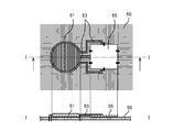
- FIG. 4 is an explanatory diagram showing an example in which a myoelectric potential sensor is sewn and fixed to the garment 50. 4 is a plan view showing the back side (human body side) of the garment 50 to which the myoelectric potential sensor is fixed, and the II cross section of the plan view is shown below.
- the electrode part 51 and the IC chip 55 constituting the myoelectric potential sensor are sewn to the clothing 50.
- the entire surface of the electrode portion 51 is covered with embroidery.
- the wiring part 53 that electrically connects the electrode part 51 and the IC chip 55 is also covered with embroidery.
- the myoelectric potential sensor 31 can be provided on the garment 50 in various modes other than being sewn on the garment 50.
- FIG. 5 shows an example in which the myoelectric potential sensors 31L and 31R are accommodated in the accommodation pocket 58 provided in the clothes 50.
- the accommodation pocket 58 is provided in advance corresponding to the arrangement position of the myoelectric potential sensors 31L and 31R.
- the accommodation pocket 58 may be provided on either the front side or the back side of the garment 50.
- the size of the accommodating pocket 58 is preferably substantially the same as the outer shape of the myoelectric potential sensors 31L and 31R. In this case, at least the electrode portion of the myoelectric potential sensors 31L and 31R may be accommodated in the accommodation pocket 58.
- the garment 50 in which the myoelectric potential sensors 31L and 31R are arranged in the accommodation pocket 58, the garment 50 may be provided with a plurality of accommodation pockets 58 so that the arrangement positions of the myoelectric potential sensors 31L and 31R can be selected.
- FIG. 6 shows an example in which a storage pocket 59 on the lower side is added to the garment 50 shown in FIG.
- the lower accommodation pockets 59 are provided on the left and right sides along the muscle fibers of the biceps femoris.
- the myoelectric potential sensors 31L and 31R may be disposed in the upper accommodation pocket 58, and the myoelectric potential sensors 31L and 31L are disposed in the lower accommodation pocket 59. 31R may be arranged. Alternatively, the user H may arrange the myoelectric potential sensors 31L and 31R in the upper and lower accommodation pockets 58 and 59, respectively.
- the accommodation pocket may be provided on the front side.
- the myoelectric potential sensor can be disposed at an appropriate position for each user H or according to the assisting operation. Thereby, a desired auxiliary operation can be appropriately obtained.
- the electrode part When the electrode part is covered with embroidery or accommodated in the accommodation pockets 58 and 59, the electrode part may be a wet electrode or a dry electrode. In this case, even if a wet electrode is used, since the electrode portion does not directly contact the human skin, it is possible to prevent skin inflammation and the development of allergic symptoms.
- control pack 26 is provided on the back side of the waist mounting portion 13.
- a control unit 25 is accommodated in the control pack 26.
- the control unit 25 acquires a myoelectric potential signal detected by the myoelectric potential sensor 31, performs arithmetic processing, and outputs a drive command to the rotary actuator 21.
- the control unit 25 includes an electronic component such as a CPU and a storage element, and is electrically connected to the myoelectric potential sensor 31 and the rotary actuator 21 through electric wiring (not shown).
- the control unit 25 and the myoelectric potential sensor 31 or the rotary actuator 21 may be connected by wireless communication means.
- the myoelectric potential signal generated with the operation of the user H is detected by the myoelectric potential sensor 31, and the control unit 25 calculates the required assisting force based on the amplitude of the myoelectric potential signal. Further, the drive torque of the rotary actuator 21 is determined by the control unit 25 based on the requested auxiliary force and transmitted to the rotary actuator 21. As a result, the rotary actuator 21 is driven to rotate, and the arm portion 23 rotates, thereby generating an assisting force for the longitudinal movement of the user H's leg.
- the myoelectric potential sensor 31 that detects the myoelectric potential signal accompanying the operation of the user H is provided on the clothes or the underwear 50 worn by the user H. .
- the myoelectric potential sensor 31 is also arrange
- an adhesive that fixes the myoelectric potential sensor 31 on the skin is not used, skin irritation, allergic symptoms, and the like are not caused.
- the myoelectric potential sensor 31 is attached in advance to a predetermined position of the clothes or the undergarment 50 in accordance with the exercise unit (muscle) corresponding to the operation of the auxiliary target,
- the arrangement position of the potential sensor 31 is not greatly shifted. Therefore, appropriate assistance in accordance with the intention of the user H is realized by the motion assisting device 1.
- the degree of freedom of the arrangement position of the myoelectric potential sensor 31 can be increased.
- the rotary actuator 21 is accommodated in the joint portion 20, but the present invention is not limited to such an example.
- the rotary actuator 21 may be disposed at a position away from the joint unit 20 and rotate the arm unit 23 via a power transmission mechanism.
- the rotary actuator 21 may be accommodated in a control pack 26 provided on the back side of the waist mounting portion 13. Alternatively, it may be accommodated together with the control unit 25 in a backpack carried by the user H.
- the myoelectric potential sensor 31 may be provided on the clothing 50 or the like so as to be disposed along the quadriceps muscle on the front side of the thigh.
- the noise can be reduced by executing the process of amplifying the difference between the two sensor values for all the sensor values. Thereby, the assist of the operation
- the motion assisting device 1 is configured as a device that assists the user H's back and forth movement of both legs, but the present invention is not limited to this example.
- the motion assisting device 1 may be a device that assists the user H in the longitudinal motion of one leg.
- the joint part 20, the arm part 23, and the thigh attachment part 17 are provided only in any one of right and left.
- the movement assisting device 1 is not limited to a device that assists the front and back movement of the thigh, and may be a device that assists the calf movement around the knee joint or a device that assists the movement of the arm. There may be.
- a myoelectric potential sensor is provided on clothes or underwear worn by the user on the upper body.
- the motion assisting device 1 includes the myoelectric potential sensor as the signal detection unit, and detects the myoelectric potential signal of the user H by the myoelectric potential sensor to control the driving of the rotary actuator 21.
- the signal detection unit may be a sensor that detects a biological signal other than the myoelectric potential signal.
- the biological signal include, but are not limited to, an electroencephalogram, a skin electroencephalogram, an electric skin reaction, or a nerve potential.
Landscapes
- Health & Medical Sciences (AREA)
- Engineering & Computer Science (AREA)
- Physical Education & Sports Medicine (AREA)
- Mechanical Engineering (AREA)
- Epidemiology (AREA)
- Pain & Pain Management (AREA)
- Robotics (AREA)
- Rehabilitation Therapy (AREA)
- Life Sciences & Earth Sciences (AREA)
- Animal Behavior & Ethology (AREA)
- General Health & Medical Sciences (AREA)
- Public Health (AREA)
- Veterinary Medicine (AREA)
- Manipulator (AREA)
Abstract
時間的な遅延を低減しつつ、ユーザの動作に応じて動作補助装置を適切に制御可能な動作補助装置を提供する。 動作補助装置は、ユーザの人体に装着され、第1の部材及び第2の部材を相対回転可能に連結する関節部を有する装着具と、第1の部材及び第2の部材を相対回転させるアクチュエータと、ユーザが身に着ける衣服又は下着に設けられ、ユーザの筋電位信号を検出する信号検出部と、検出された筋電位信号に基づいてアクチュエータの駆動制御を行う制御部と、を備える。
Description
本発明は、人体に装着して用いられる動作補助装置に関する。
近年、歩行動作や手足の曲げ伸ばし動作等の人の動作を補助する動作補助装置が知られている。動作補助装置は、人体に装着して用いられ、ユーザの手足の動きに合わせて作動することによって、ユーザの動作を補助する。例えば、動作補助装置は、身体の関節部分に対応して配置される回転軸を中心に回動可能なアーム部材を備え、アクチュエータによってアーム部材を回転させることによって、アーム部材が固定された身体の部分の動作を補助する。かかる動作補助装置は、例えば、障害者又は高齢者だけでなく、健常者の動作を補助する装置等としても、様々な場面で使用され得る。
ここで、非特許文献1に記載されているように、人の動作は、人体の骨格筋の収縮によって実現されている。骨格筋が収縮する際、筋線維は、運動ニューロンの刺激に反応して電気的な活動を引き起こす。運動ニューロンと、当該運動ニューロンが神経支配する筋線維は、運動単位(MU)と呼ばれる機能的構造体と考えられている。骨格筋の電気的な活動は、皮膚の表面に電極を配置することによって観察することができる。この手法は、筋電図検査として知られており、観察された電気信号が筋電位である。
表面筋電図(sEMG)に基づいて行われる動作補助装置の制御として、種々の方法が知られている。筋電位信号の振幅の大きさは、動作補助装置を所望の補助力で作動させるための情報として用いられる。表面筋電図を取得するための筋電位センサは、筋電位の検出対象となる所望の筋肉を覆う皮膚上に取付けられる。筋電位センサにおいて使用される電極としては、湿式の電極又は乾式の電極がある。
ここで、湿式又は乾式いずれの電極においても、実用面で不都合が生じ得る。例えば、電極を皮膚に固定するための粘着剤、あるいは、湿式の電極における導電性ゲルは、皮膚の炎症やアレルギ症状を引き起こすおそれがある。また、湿式の電極における導電性ゲルは、乾燥に伴って信号の質の劣化を生じ得る。さらに、湿式及び乾式いずれの電極においても汗や筋肉の収縮により皮膚表面から外れる場合があるため、これを避けるために、電極の取付位置の体毛を除去したり、電極を取り付ける前にアルコール由来の洗浄液等によって皮膚を洗浄したりする必要がある。
これに対して、上記の不都合を回避するために、非特許文献2に記載されたように、外骨格ロボットの制御に用いる電極、あるいは、日常の生体信号の監視に用いられる電極として、非接触式の静電容量型筋電位センサが提案されている。
Campbell N. A., and J. B. Reece. Biology. 7th ed. San Francisco: Pearson, 2005. 1066-1068.
Ianov A.I. et al, Development of a Capacitive Coupling Electrode for Bioelectrical Signal Measurements and Assistive Device Use, 2012.
湿式及び乾式いずれの電極が用いられる場合であっても、当該電極は、動作補助装置を使用するたびに、ユーザあるいは専門スタッフによってユーザの皮膚上に取り付けられ、動作補助装置の使用後には、毎回取り外される。当該電極の取付け及び取外しは、少なからず時間を要する作業である。また、検出される筋電位信号の質は、筋線維に対する筋電位センサの電極の位置に大きく依存する。したがって、ユーザあるいは専門スタッフは、電極が、毎回、ほぼ同じ位置に、正確に配置されるようにしなければならなかった。
本発明は、上記問題に鑑みてなされたものであり、本発明の目的とするところは、電極の取付け及び取外しに要する時間を削減し、かつ、電極の配置位置を保障可能な、新規かつ改良された動作補助装置を提供することにある。
上記課題を解決するために、本発明のある観点によれば、ユーザの人体に装着され、第1の部材及び第2の部材を相対回転可能に連結する関節部を有する装着具と、第1の部材及び第2の部材を相対回転させるアクチュエータと、ユーザが身に着ける衣服又は下着に設けられ、ユーザの生体信号を検出する信号検出部と、検出された生体信号に基づいてアクチュエータの駆動制御を行う制御部と、を備えた、動作補助装置が提供される。
本発明の動作補助装置によれば、所望の筋肉の生体信号を検出するための信号検出部が、ユーザが身に着ける衣服又は下着に設けられる。したがって、ユーザが衣服等を身に着け、あるいは、脱ぐことにより、信号検出部の配置及び取外しが行われることになり、電極の配置及び取外しに要する時間を短縮することができる。また、衣服又は下着に信号検出部が設けられていることにより、衣服等を身に着けたときに、人体に対して電極がほぼ同じ位置に配置され得る。したがって、動作補助装置の使用ごとの生体信号の質のばらつきが低減され、筋電位信号の質を向上させることができる。
生体信号は、筋電位信号であってもよい。
信号検出部は、筋電位信号の検出対象となる運動単位上の位置に対応させて配置されてもよい。
信号検出部は、運動単位上に配置された少なくとも1つの表面筋電位検出電極を含んでもよい。
信号検出部の少なくとも一部が、刺繍により被覆されつつ衣服又は下着に縫製されてもよい。
信号検出部の少なくとも一部が、衣服又は下着に設けられた収容ポケットに収容されてもよい。
信号検出部が、静電容量型のセンサであってもよい。
以上説明したように本発明によれば、電極の取付け及び取外しに要する時間を削減し、かつ、電極の配置位置を保障することができる。
以下に添付図面を参照しながら、本発明の好適な実施の形態について詳細に説明する。なお、本明細書及び図面において、実質的に同一の機能構成を有する構成要素については、同一の符号を付することにより重複説明を省略する。
図1~図2を参照して、本実施形態にかかる動作補助装置1の全体構成例について説明する。図1は、動作補助装置1を装着したユーザHを正面から見た図であり、図2は、動作補助装置1を装着したユーザHを側方(左側)から見た図である。
本実施形態にかかる動作補助装置1は、歩行動作又は階段昇降動作等の左右の脚の前後運動の動作を補助するための装置であり、いわゆる外骨格ロボットとも呼ばれる。動作補助装置1は、装着具10と、回転アクチュエータ21と、筋電位センサ31と、制御ユニット25とを備える。本実施形態にかかる動作補助装置1において、装着具10は、腰装着部13と、固定ベルト11と、アーム部23と、大腿部装着部17と、固定ベルト15とを備える。
装着具10のうち、腰装着部13、アーム部23及び大腿部装着部17は、例えば、樹脂材料により形成され、所定程度の剛性を有する。したがって、腰装着部13、アーム部23及び大腿部装着部17は、変形しにくくなっている。一方、固定ベルト11及び固定ベルト15は、ユーザHの体格によって固定ベルト11,15の締め付け具合が変えられるように、織物、編物又は樹脂等により形成され、変形可能になっていてもよい。
腰装着部13は、ユーザHの腰部に装着され、固定ベルト11により固定される。腰装着部13は第1の部材の一例であり、固定ベルト11は第1の固定部の一例である。固定ベルト11は、腰装着部13に対して、例えば、面ファスナーやスナップボタン等の固定具によって取り付けられている。固定ベルト11は、例えば、バックル又は面ファスナー等の連結具を有し、連結具を連結させることにより固定ベルト11が腰部に巻き付けられ、腰装着部13が固定され得る。固定ベルト11は、ベルトを折り返して長さを調節可能なアジャスタ等の長さ調節部を備えていてもよい。
腰装着部13のうち、人体の側部に位置する部分には、関節部20が設けられている。関節部20は、ユーザHの腰関節の位置に対応するように設けられる。関節部20では、アーム部23と腰装着部13とが相対的に回転可能に連結されている。アーム部23は第2の部材の一例である。例えば、関節部20に設けられた図示しない回転軸に対して、アーム部23が回動可能に支持されていてもよい。アーム部23は、関節部20から下方に延設され、アーム部23の下方側には、大腿部装着部17が設けられている。図2に示した例では、大腿部装着部17は、アーム部23の一部として構成されている。
大腿部装着部17は、ユーザHの脚部のうちの大腿部の下方に装着され、固定ベルト15により固定される。固定ベルト15は、大腿部装着部17に対して、例えば、面ファスナーやスナップボタン等の固定具によって取り付けられている。また、固定ベルト15は、バックル又は面ファスナー等の連結具を有し、連結具を連結させることにより固定ベルト15が大腿部に巻き付けられ、大腿部装着部17が固定され得る。固定ベルト15は、ベルトを折り返して長さを調節可能なアジャスタ等の長さ調節部を備えていてもよい。大腿部装着部17及び固定ベルト15は第2の固定部の一例である。
関節部20の内部には、回転アクチュエータ21が備えられている。回転アクチュエータ21としては、例えば、ステッピングモータ又はブラシレスモータが用いられる。回転アクチュエータ21は、減速機を備えてもよい。また、回転アクチュエータ21は、回転式のロータリーモータを用いたアクチュエータに限らず、リニアモータと回転機構とを備えたアクチュエータであってもよい。かかる回転アクチュエータ21を駆動させることにより、関節部20を中心にアーム部23が回動する。これにより、大腿部装着部17が装着されたユーザHの大腿部の前後方向の動きが補助される。
また、動作補助装置1は、ユーザHの筋電位信号を検出するための筋電位センサ31を有する。筋電位センサ31が、本発明における信号検出部に相当する。筋電位センサ31は、ユーザHの左右の臀部の上部に配置された2個の表面筋電位検出電極(以下、単に「表面電極」という。)を含む。2個の表面電極は、左右の臀部の上部にそれぞれ配置される。筋電位センサ31は、動作補助装置1により補助される筋力に対応する運動単位(筋肉)に応じてあらかじめ位置が決定されて、ユーザHが身に着ける衣服又は下着(以下、単に「衣服」ともいう。)50に設けられる。つまり、筋電位センサ31は、個別にユーザHの人体に直接取り付けられるものではなく、衣服50を身に着けることにより同時に人体の皮膚表面に配置されるものとなっている。なお、表面電極は1個であってもよいし、3個以上であってもよい。
本実施形態にかかる動作補助装置1は、ユーザHの脚の前後運動を補助する装置であるため、これらの筋電位センサ31の表面電極は、装着時においてユーザHの大殿筋の筋電位を検出可能な位置に配置される。このとき、それぞれの筋電位センサ31の2つの電極は、できる限り近接して配置されてもよい。さらには、それぞれの筋電位センサ31の2つの電極は、運動単位の筋線維の方向に沿って配列されてもよい。これにより、同じ筋線維の筋電位が検出されやすくなり、2つの検出値の差分を求めてノイズを低減させることができる。
図3は、筋電位センサ31L,31Rが設けられた衣服50の一例を示している。図3は、衣服50を背面側から見た図である。筋電位センサ31L,31Rは、左右の臀部の上部に、大殿筋の筋線維の方向に沿って配置されている。かかる筋電位センサ31L,31Rは、例えば、衣服50の内側に設けられてもよい。筋電位センサ31L,31Rが衣服50の内側に設けられることにより、筋電位センサ31L,31Rと大殿筋との距離が近付けられ、筋電位信号の検出精度が向上する。
筋電位センサ31L,31Rには、例えば、他端にコネクタを有する電気配線の一端が接続され、制御ユニット25にコネクタを接続することによって、筋電位センサ31L,31Rと制御ユニット25との間で信号の送受信が可能になっていてもよい。あるいは、筋電位センサ31L,31Rと制御ユニット25とは、無線通信によって信号の送受信が可能になっていてもよい。
筋電位センサ31L,31Rとしては、例えば、静電容量型のセンサが用いられる。静電容量型の筋電位センサ31L,31Rでは、検出される筋電位に応じて静電容量が変化し、当該静電容量の変化が電気信号に変換されて出力される。静電容量型の筋電位センサ31L,31Rであれば、皮膚の表面に直接接触させることなく、所望の筋肉の筋電位を検出することができる。したがって、筋電位センサ31L,31Rが、衣服50に設けられる場合だけでなく、衣服に設けられる場合であっても、筋電位信号を検出することができる。
静電容量型の筋電位センサ31L,31Rが用いられる場合、筋電位センサ31L,31Rは、例えば、電極部、発振回路及び出力回路を備える。また、筋電位センサ31L,31Rは、AD変換器及び増幅器を備えてもよい。筋電位センサ31の電極部は、例えば、単極型、双極型又は三極型の電極であってよく、さらに、アレイ型又はマトリックス型の電極であってもよい。
筋電位センサ31は、例えば、衣服50に縫い付けられて固定されてもよい。図4は、衣服50に筋電位センサが縫い付けられて固定された例を示す説明図である。図4の上方には筋電位センサが固定された衣類50の裏面側(人体側)を示す平面図が示され、当該平面図のI-I断面が下方に示されている。
図4に示した例では、筋電位センサを構成する電極部51及びICチップ55が衣類50に縫い付けられている。電極部51は、表面全体が刺繍により被覆されている。また、電極部51とICチップ55とを電気的に接続する配線部53も、刺繍により被覆されている。このように筋電位センサを衣服50に固定することにより、筋電位センサが強固に衣服50に固定され得る。また、筋電位センサが衣服50の表面から大きく突出することがないため、衣服50を身に着けた時の違和感や不快感を低減することができる。
また、筋電位センサ31は、衣服50に縫い付けられる以外に、様々な態様で衣服50に設けられ得る。図5は、衣服50に設けられた収容ポケット58に筋電位センサ31L,31Rを収容した例を示している。収容ポケット58は、筋電位センサ31L,31Rの配置位置に対応してあらかじめ設けられる。収容ポケット58は、衣服50の表側又は裏側のいずれに設けられてもよい。収容ポケット58の内部で筋電位センサ31L,31Rが移動しないように、収容ポケット58の大きさは、筋電位センサ31L,31Rの外形とほぼ同一にされるとよい。この場合、筋電位センサ31L,31Rのうち、少なくとも電極部が収容ポケット58に収容されてよい。
収容ポケット58内に筋電位センサ31L,31Rが配置される衣服50の場合、衣服50に複数の収容ポケット58が設けられ、筋電位センサ31L,31Rの配置位置が選択可能になっていてもよい。図6は、図5に示した衣服50に、下方側の収容ポケット59を追加した例を示している。下方側の収容ポケット59は、大腿二頭筋の筋線維に沿って左右それぞれ2個設けられている。ユーザHは、脚の前後運動に伴う筋電位信号を検出するにあたり、上方側の収容ポケット58に筋電位センサ31L,31Rを配置してもよく、下方側の収容ポケット59に筋電位センサ31L,31Rを配置してもよい。あるいは、ユーザHは、上方側及び下方側の収容ポケット58,59それぞれに筋電位センサ31L,31Rを配置してもよい。
なお、収容ポケットは、前面側に設けられてもよい。収容ポケットを種々異なる位置に設けることによって、ユーザHごとに、あるいは、補助させる動作に応じて、適切な位置に筋電位センサを配置することができる。これにより、所望の補助動作が適切に得られるようになる。
電極部が、刺繍により被覆され、あるいは、収容ポケット58,59内に収容される場合、電極部は、湿式の電極であってもよいし、乾式の電極であってもよい。この場合、湿式の電極が用いられても、人体の皮膚に直接電極部が接することがないため、皮膚の炎症やアレルギ症状の発現を防ぐことができる。
図1及び図2に戻り、腰装着部13の背中側には制御パック26が備えられる。制御パック26内には制御ユニット25が収容されている。制御ユニット25は、筋電位センサ31により検出される筋電位信号を取得して演算処理を行い、回転アクチュエータ21に対して駆動指令を出力する。制御ユニット25は、CPU及び記憶素子等の電子部品を備えて構成され、図示しない電気配線により筋電位センサ31及び回転アクチュエータ21に電気的に接続される。制御ユニット25と、筋電位センサ31又は回転アクチュエータ21とは、無線の通信手段によって接続されてもよい。
かかる動作補助装置1では、ユーザHの動作に伴って生成される筋電位信号が筋電位センサ31により検出され、制御ユニット25が当該筋電位信号の振幅に基づき要求補助力を算出する。また、制御ユニット25により、当該要求補助力に基づいて回転アクチュエータ21の駆動トルクが決定され、回転アクチュエータ21に送信される。これにより、回転アクチュエータ21が回転駆動され、アーム部23が回転することによって、ユーザHの脚の前後動作に対する補助力が生成される。
以上説明したように、本実施形態にかかる動作補助装置1では、ユーザHの動作に伴う筋電位信号を検出する筋電位センサ31が、ユーザHが身に付ける衣服又は下着50に設けられている。このため、ユーザHが衣服等50を身に着けることによって、同時に筋電位センサ31も所望の位置に配置される。したがって、筋電位センサ31の取付け及び取外しに要する時間を削減することができる。また、筋電位センサ31を皮膚上に固定する粘着剤を用いることもないため、皮膚の炎症やアレルギ症状等が引き起こされることもない。
また、筋電位センサ31は、補助対象の動作に対応する運動単位(筋肉)に応じて、衣服又は下着50の所定の位置にあらかじめ取り付けられるために、衣服等50を身に着けるごとに、筋電位センサ31の配置位置が大きくずれることがない。したがって、動作補助装置1によって、ユーザHの意図に沿った適切な補助が実現される。また、衣服等50に、筋電位センサ31を収容する収容ポケットを複数の位置に設けることによって、筋電位センサ31の配置位置の自由度も高められる。
以上、添付図面を参照しながら本発明の好適な実施形態について詳細に説明したが、本発明はかかる例に限定されない。本発明の属する技術の分野における通常の知識を有する者であれば、特許請求の範囲に記載された技術的思想の範疇内において、各種の変更例または修正例に想到し得ることは明らかであり、これらについても、当然に本発明の技術的範囲に属するものと了解される。
例えば、上記実施形態では、回転アクチュエータ21が関節部20に収容される構成となっていたが、本発明はかかる例に限られない。例えば、回転アクチュエータ21は、関節部20から離れた位置に配置されて、動力伝達機構を介してアーム部23を回動させるものであってもよい。また、例えば、回転アクチュエータ21が、腰装着部13の背中側に設けられた制御パック26内に収容されてもよい。あるいは、ユーザHが背負うバックパック等に、制御ユニット25とともに収容されていてもよい。
また、上記実施形態では、筋電位センサ31が、大殿筋の上部又は大腿二頭筋の下部に配置される例を示したが、本発明はかかる例に限定されない。例えば、筋電位センサ31は、大腿部の前面側に大腿四頭筋に沿って配置されるように衣服等50に設けられてもよい。また、筋電位センサ31が増えるほど、2つのセンサ値の差分を増幅する処理をすべてのセンサ値に対して実行することによって、ノイズを低減させることができる。これにより、動作補助装置1によるユーザHの動作のアシストを適切に実行することができる。
また、上記実施形態では、動作補助装置1が、ユーザHの両脚の前後運動を補助する装置として構成されていたが、本発明はかかる例に限定されない。例えば、動作補助装置1は、ユーザHの片脚の前後運動を補助する装置であってもよい。この場合、関節部20、アーム部23及び大腿部装着部17は、左右のいずれか一方にのみ設けられる。また、動作補助装置1は、大腿部の前後運動を補助する装置に限られず、ひざ関節を中心としたふくらはぎの動作を補助する装置であってもよいし、腕の動作を補助する装置であってもよい。腕の動作を補助する動作補助装置とする場合、例えば、ユーザが上半身に身に付ける衣服や下着に筋電位センサが設けられる。
また、上記実施形態では、動作補助装置1が、信号検出部として筋電位センサを備え、筋電位センサによりユーザHの筋電位信号を検出して回転アクチュエータ21の駆動制御を行っていたが、本発明はかかる例に限定されない。例えば、信号検出部は、筋電位信号以外の生体信号を検出するセンサであってよい。生体信号としては、例えば、脳波、皮膚脳波、電気皮膚反応、又は神経電位などが挙げられるが、これに限定されない。
Claims (7)
- ユーザの人体に装着され、第1の部材及び第2の部材を相対回転可能に連結する関節部を有する装着具と、
前記第1の部材及び前記第2の部材を相対回転させるアクチュエータと、
前記ユーザが身に着ける衣服又は下着に設けられ、前記ユーザの生体信号を検出する信号検出部と、
検出された前記生体信号に基づいて前記アクチュエータの駆動制御を行う制御部と、を備えた、動作補助装置。 - 前記生体信号は、筋電位信号である、請求項1に記載の動作補助装置。
- 前記信号検出部は、前記筋電位信号の検出対象となる運動単位上の位置に対応させて配置される、請求項2に記載の動作補助装置。
- 前記信号検出部は、前記運動単位上に配置された少なくとも1つの表面筋電位検出電極を含む、請求項3に記載の動作補助装置。
- 前記信号検出部の少なくとも一部が、刺繍により被覆されつつ前記衣服又は下着に縫製される、請求項1~4のいずれか1項に記載の動作補助装置。
- 前記信号検出部の少なくとも一部が、衣服又は下着に設けられた収容ポケットに収容される、請求項1~4のいずれか1項に記載の動作補助装置。
- 前記信号検出部が、静電容量型のセンサである、請求項1~6のいずれか1項に記載の動作補助装置。
Applications Claiming Priority (2)
| Application Number | Priority Date | Filing Date | Title |
|---|---|---|---|
| JP2016090017 | 2016-04-28 | ||
| JP2016-090017 | 2016-04-28 |
Publications (1)
| Publication Number | Publication Date |
|---|---|
| WO2017187660A1 true WO2017187660A1 (ja) | 2017-11-02 |
Family
ID=60160206
Family Applications (1)
| Application Number | Title | Priority Date | Filing Date |
|---|---|---|---|
| PCT/JP2016/086478 Ceased WO2017187660A1 (ja) | 2016-04-28 | 2016-12-08 | 動作補助装置 |
Country Status (1)
| Country | Link |
|---|---|
| WO (1) | WO2017187660A1 (ja) |
Cited By (1)
| Publication number | Priority date | Publication date | Assignee | Title |
|---|---|---|---|---|
| JP2023158703A (ja) * | 2022-04-19 | 2023-10-31 | 群馬県 | 圧力・近接センサおよび圧力・近接センサシートおよび着座位置検出システム。 |
Citations (4)
| Publication number | Priority date | Publication date | Assignee | Title |
|---|---|---|---|---|
| JP2003339908A (ja) * | 2002-05-24 | 2003-12-02 | Advanced Telecommunication Research Institute International | トレーニング装置 |
| JP2008501376A (ja) * | 2004-06-04 | 2008-01-24 | ユニヴェルシテ リブル ドゥ ブリュッセル | 患者の肢筋挙動の監視に適応された医療装置 |
| JP2009261735A (ja) * | 2008-04-25 | 2009-11-12 | Ritsumeikan | 静電容量型電極を用いた筋電の計測装置および計測方法 |
| WO2010029966A1 (ja) * | 2008-09-10 | 2010-03-18 | 国立大学法人筑波大学 | 生体信号計測装着具及び装着式動作補助装置 |
-
2016
- 2016-12-08 WO PCT/JP2016/086478 patent/WO2017187660A1/ja not_active Ceased
Patent Citations (4)
| Publication number | Priority date | Publication date | Assignee | Title |
|---|---|---|---|---|
| JP2003339908A (ja) * | 2002-05-24 | 2003-12-02 | Advanced Telecommunication Research Institute International | トレーニング装置 |
| JP2008501376A (ja) * | 2004-06-04 | 2008-01-24 | ユニヴェルシテ リブル ドゥ ブリュッセル | 患者の肢筋挙動の監視に適応された医療装置 |
| JP2009261735A (ja) * | 2008-04-25 | 2009-11-12 | Ritsumeikan | 静電容量型電極を用いた筋電の計測装置および計測方法 |
| WO2010029966A1 (ja) * | 2008-09-10 | 2010-03-18 | 国立大学法人筑波大学 | 生体信号計測装着具及び装着式動作補助装置 |
Cited By (3)
| Publication number | Priority date | Publication date | Assignee | Title |
|---|---|---|---|---|
| JP2023158703A (ja) * | 2022-04-19 | 2023-10-31 | 群馬県 | 圧力・近接センサおよび圧力・近接センサシートおよび着座位置検出システム。 |
| JP2023164998A (ja) * | 2022-04-19 | 2023-11-14 | 群馬県 | 圧力・近接センサおよび圧力・近接センサシートおよび着座位置検出システム |
| JP7384336B2 (ja) | 2022-04-19 | 2023-11-21 | 群馬県 | 圧力・近接センサおよび圧力・近接センサシートおよび着座位置検出システム。 |
Similar Documents
| Publication | Publication Date | Title |
|---|---|---|
| CN102149318B (zh) | 生物体信号测量穿戴用具和穿戴式动作辅助装置 | |
| CN107997929B (zh) | 一种基于主动意图控制的便携式踝关节康复机器人 | |
| JP5961331B2 (ja) | ユーザー結合ヒューマン・マシン・インターフェース | |
| CN104434470B (zh) | 一种用于辅助行走的下肢外骨骼机器人 | |
| CN109172265B (zh) | 手指外骨骼机器人 | |
| JP5569885B2 (ja) | 足関節駆動による歩行支援機能的電気刺激システム | |
| KR20080080035A (ko) | 상체 착용형 근력 보조 증폭 장치 | |
| JP2014023795A (ja) | 情報生成装置並びに情報生成方法、情報生成用プログラム及び情報記録媒体 | |
| US20170127962A1 (en) | Biological-signal measurement device, biological-signal measurement method, wearable action assistance device, and action assistance method | |
| WO2017187660A1 (ja) | 動作補助装置 | |
| JP2018134724A (ja) | 動作推定装置及び動作補助装置 | |
| KR20150090354A (ko) | 보행 보조 로봇을 이용한 근육 재활 훈련 제어 방법 | |
| EP3530183B1 (en) | Wearable electrode | |
| WO2017187659A1 (ja) | 動作補助装置 | |
| WO2020184118A1 (ja) | 治療機器、治療システム、治療機器の制御方法、及び治療機器の制御方法プログラム | |
| KR20230052803A (ko) | 마그넷을 포함하는 운동 보조 장치 | |
| KR20230052236A (ko) | 재구성 가능한 운동 보조 장치 | |
| Garcia et al. | Development of the atlas lower-limb active orthosis | |
| EP4613254A1 (en) | Device and method for improving movement function | |
| JP6363467B2 (ja) | 生体電位計測装置 | |
| CN114932536B (zh) | 可行走的主动式机械装置 | |
| KR20230052205A (ko) | 재구성 가능한 운동 보조 장치 | |
| JP2018153314A (ja) | 非接触式筋電位センサ | |
| Kaur et al. | Influence of gender on muscle activity patterns during normal and fast walking | |
| HK1158044B (en) | Wearing tool for measuring biological signal, and wearing-type motion assisting device |
Legal Events
| Date | Code | Title | Description |
|---|---|---|---|
| NENP | Non-entry into the national phase |
Ref country code: DE |
|
| 121 | Ep: the epo has been informed by wipo that ep was designated in this application |
Ref document number: 16900530 Country of ref document: EP Kind code of ref document: A1 |
|
| 122 | Ep: pct application non-entry in european phase |
Ref document number: 16900530 Country of ref document: EP Kind code of ref document: A1 |
|
| NENP | Non-entry into the national phase |
Ref country code: JP |