WO2017187658A1 - 動作補助装置 - Google Patents
動作補助装置 Download PDFInfo
- Publication number
- WO2017187658A1 WO2017187658A1 PCT/JP2016/086476 JP2016086476W WO2017187658A1 WO 2017187658 A1 WO2017187658 A1 WO 2017187658A1 JP 2016086476 W JP2016086476 W JP 2016086476W WO 2017187658 A1 WO2017187658 A1 WO 2017187658A1
- Authority
- WO
- WIPO (PCT)
- Prior art keywords
- unit
- signal
- assisting device
- myoelectric potential
- motor unit
- Prior art date
- Legal status (The legal status is an assumption and is not a legal conclusion. Google has not performed a legal analysis and makes no representation as to the accuracy of the status listed.)
- Ceased
Links
Images




Classifications
-
- A—HUMAN NECESSITIES
- A61—MEDICAL OR VETERINARY SCIENCE; HYGIENE
- A61B—DIAGNOSIS; SURGERY; IDENTIFICATION
- A61B5/00—Measuring for diagnostic purposes; Identification of persons
- A61B5/24—Detecting, measuring or recording bioelectric or biomagnetic signals of the body or parts thereof
- A61B5/316—Modalities, i.e. specific diagnostic methods
- A61B5/389—Electromyography [EMG]
-
- A—HUMAN NECESSITIES
- A61—MEDICAL OR VETERINARY SCIENCE; HYGIENE
- A61H—PHYSICAL THERAPY APPARATUS, e.g. DEVICES FOR LOCATING OR STIMULATING REFLEX POINTS IN THE BODY; ARTIFICIAL RESPIRATION; MASSAGE; BATHING DEVICES FOR SPECIAL THERAPEUTIC OR HYGIENIC PURPOSES OR SPECIFIC PARTS OF THE BODY
- A61H3/00—Appliances for aiding patients or disabled persons to walk about
-
- B—PERFORMING OPERATIONS; TRANSPORTING
- B25—HAND TOOLS; PORTABLE POWER-DRIVEN TOOLS; MANIPULATORS
- B25J—MANIPULATORS; CHAMBERS PROVIDED WITH MANIPULATION DEVICES
- B25J11/00—Manipulators not otherwise provided for
Definitions
- the present invention relates to an operation assisting device that is worn on a human body.
- motion assist devices that assist human motion such as walking motion and bending and stretching motion of limbs are known.
- the motion assisting device is attached to a human body and operates in accordance with the movement of the user's limbs to assist the user's motion.
- the motion assisting device includes an arm member that can be rotated around a rotation shaft that is arranged corresponding to a joint portion of the body, and the arm member is rotated by an actuator so that the arm member is fixed. Assist the operation of the part.
- Such a motion assisting device can be used in various situations, for example, as a device that assists not only a disabled person or an elderly person but also a healthy person.
- Non-Patent Document 1 human movement is realized by contraction of human skeletal muscles.
- muscle fibers undergo electrical activity in response to stimulation of motor neurons.
- Motor neurons and the muscle fibers that are innervated by the motor neurons are considered functional structures called motor units (MUs).
- the electrical activity of skeletal muscle can be observed by placing electrodes on the surface of the skin. This technique is known as electromyography, and the observed electrical signal is myoelectric potential.
- electromyography surface electromyography (sEMG) is used to detect the movement of muscles using electrodes placed on the surface of the skin, and electrodes are placed on or inside muscles and nerve fibers.
- EMG electromyography
- various methods are known as the control of the motion assist device performed based on the surface electromyogram.
- the magnitude of the amplitude of the myoelectric potential signal is used as information for operating the motion assisting device with a desired assisting force.
- a method for obtaining the amplitude of the myoelectric signal for example, an envelope (envelope) extraction process, an average rectified current calculation process, or an RMS value (root mean square) calculation process is used.
- Non-Patent Document 2 it is known that the control method of the motion assist device performed based on the surface electromyogram has a large variation between subjects.
- Electrodes for detecting myoelectric potential signals are usually placed by specialist staff due to electrode position restrictions and subject-to-subject variation, and the usage environment of motion assist devices is substantially limited to the clinical environment. . Further, the processing of the myoelectric potential signal according to the above example may cause a time delay from the acquisition of the myoelectric potential signal until the operation assisting device is driven, and the performance of the operation assisting device may be impaired. .
- the present invention has been made in view of the above problems, and an object of the present invention is to provide a novel device capable of appropriately controlling an operation assisting device according to a user's operation while reducing a time delay. Another object of the present invention is to provide an improved motion assisting device.
- a signal detection unit that detects a myoelectric potential signal of a user, an extraction processing unit that extracts a motor unit action potential from the acquired myoelectric potential signal, and extraction A combined processing unit that obtains the required auxiliary force by superimposing the muscular strengths of each of the motor unit action potentials, and a torque calculation that calculates the driving torque of the actuator that drives the motion auxiliary device worn by the user based on the required auxiliary force A motion assisting device.
- the synthesis processing unit obtains the requested assisting force by superimposing the muscle forces corresponding to the motor unit action potential extracted from the myoelectric potential signal, and the torque calculating unit based on the requested assisting force
- the driving torque of the actuator is calculated. Accordingly, a delay in time from when the myoelectric potential signal is detected to when the driving torque is output to the actuator is reduced, and an operation assisting device that can appropriately assist the user's operation can be obtained.
- such an operation assisting device is excellent in stability against changes in signal transmission conditions due to differences in electrode installation positions and the like. Therefore, the inter-subject variation can also be reduced.
- the extraction processing unit may extract information on the frequency or frequency of the extracted motor unit action potential.
- the extraction processing unit may extract the motor unit action potential from the myoelectric potential signal using a wavelet transform, a wavelet packet, a Fourier transform, a template matching algorithm, a fuzzy discriminator, or a machine learning algorithm.
- the unit muscle strength may be set in advance according to the motor unit to be detected by the myoelectric potential signal.
- the signal detection unit may include at least one surface myoelectric potential detection electrode arranged on the motor unit.
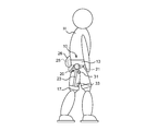
- FIG. 1 is a diagram of a user wearing the motion assisting device 10 as viewed from the front
- FIG. 2 is a diagram of the user wearing the motion assisting device 10 as viewed from the side.
- the motion assisting device 10 is a device for assisting the motions of the left and right legs such as walking motion and stair climbing motion, and is also called a so-called exoskeleton robot.
- the motion assisting device 10 includes a waist mounting part 13, a thigh mounting part 17, a rotary actuator 21, an arm part 23, myoelectric potential sensors 31 and 33, and a control unit 25.
- the waist attachment portion 13 is attached to the waist portion of the user H and fixed by the fixing belt 11.
- a joint portion 20 is provided in a portion of the waist mounting portion 13 that is located on the side of the human body.
- the joint portion 20 is provided so as to correspond to the position of the hip joint of the user H.
- the arm part 23 and the waist mounting part 13 are connected so as to be relatively rotatable.
- the arm portion 23 extends downward from the joint portion 20, and a thigh attachment portion 17 is provided on the lower side of the arm portion 23.
- the thigh mounting portion 17 is mounted on the thigh of the leg portions of the user H and is fixed by the fixing belt 15.
- the joint portion 20 is provided with a rotation actuator 21, and the arm portion 23 rotates around the joint portion 20 by driving the rotation actuator 21. Thereby, the movement of the user's H to which the thigh mounting part 17 was mounted
- the motion assisting device 10 has myoelectric potential sensors 31 and 33 for detecting the myoelectric potential signal of the user H.
- the myoelectric potential sensors 31 and 33 include two surface electrodes provided on the upper and lower portions of the thigh of the user H, respectively.
- the surface electrodes of the myoelectric potential sensors 31 and 33 are attached to the surface of the thigh of the user H so as to correspond to the positions of muscle groups constituting a desired exercise unit.
- the surface electrodes of the myoelectric potential sensors 31 and 33 may be attached to the skin surface using an adhesive sheet, or may be arranged by other methods.
- the number of the myoelectric potential sensors 31 and 33 provided is not specifically limited.
- a control pack 26 is provided on the back side of the waist mounting portion 13.
- a control unit 25 is accommodated in the control pack 26.
- the control unit 25 acquires myoelectric potential signals detected by the myoelectric potential sensors 31 and 33, performs arithmetic processing, and outputs a drive command to the rotary actuator 21.
- the control unit 25 includes an electronic component such as a CPU and a storage element, and is electrically connected to the myoelectric potential sensors 31 and 33 and the rotary actuator 21 through electric wiring (not shown).
- the control unit 25 and the myoelectric potential sensors 31, 33 or the rotary actuator 21 may be connected by wireless communication means.
- the myoelectric potential signal generated in accordance with the motion of the user H is detected by the myoelectric potential sensors 31 and 33, and the control unit 25 calculates the required assist torque by processing the myoelectric potential signal. . Further, the drive torque of the rotary actuator 21 is determined by the control unit 25 based on the required auxiliary torque and transmitted to the rotary actuator 21. As a result, the rotary actuator 21 is driven to rotate, and the arm portion 23 rotates, thereby generating an assisting force for the longitudinal movement of the user H's leg.
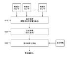
- FIG. 3 is a block diagram illustrating a configuration example of a control system of the motion assist device 10 according to the present embodiment.
- the motion assisting device 10 includes myoelectric potential sensors 31 and 33 as signal detection units, a signal processing unit 110, a drive control unit 120 as a torque calculation unit, and a rotary actuator 21.
- the signal processing unit 110 includes an extraction processing unit 112, a synthesis processing unit 114, and an auxiliary force calculation unit 116.
- the signal processing unit 110 is configured by, for example, a microcomputer, and the functions of the extraction processing unit 112, the synthesis processing unit 114, and the auxiliary force calculation unit 116 can be realized by executing a program by the microcomputer.
- the drive control unit 120 can be configured by a microcomputer, for example.
- the signal processing unit 110 and the drive control unit 120 may be configured by different microcomputers or may be realized by one microcomputer.
- the rotary actuator 21 is provided at the joint portion 20 of the motion assisting device 10 and rotates the arm portion 23 relative to the waist mounting portion 13 around the joint portion 20.
- a stepping motor or a brushless motor can be used as the rotary actuator 21.
- the rotary actuator 21 may include a speed reducer.
- the rotary actuator 21 is not limited to an actuator using a rotary rotary motor, and may be an actuator including a linear motor and a rotation mechanism.
- the myoelectric potential sensors 31 and 33 include, for example, at least one surface myoelectric potential detection electrode (surface electrode), at least one AD converter, and at least one amplifier.
- the surface electrode is attached to the surface of the skin located in the abdominal part of the muscle of a desired motor unit corresponding to the motion that can be supported by the motion assist device 10.
- the myoelectric potential sensors 31 and 33 have two surface electrodes attached to the upper and lower portions of the muscle on the front side of the thigh.
- the surface electrode derives a myoelectric potential signal Sm of a motor unit transmitted by volume conduction from the surface of the skin.
- the surface electrode detects a myoelectric potential generated by a muscle fiber.
- the surface electrode may be, for example, a monopolar, bipolar or tripolar electrode, and may be an array type or matrix type electrode.
- the number of surface electrodes may be one, or three or more.
- the AD converter converts the myoelectric potential signal Sm acquired by the surface electrode into a digital signal.
- the amplifier amplifies and outputs the digital signal converted by the AD converter.
- the AD converter and the amplifier may be provided integrally on the surface electrode attached to the skin surface, or may be provided on the control unit 25 side that acquires the myoelectric potential signal Sm from the surface electrode.
- the myoelectric potential sensors 31 and 33 may include a filter for reducing noise of the detected myoelectric potential signal Sm.
- Various filters such as LPF (low-pass filter), HPF (high-pass filter), and BPF (band-pass filter) can be appropriately used as the filter according to the amplitude of the noise signal to be removed.
- the signal processing unit 110 processes the acquired myoelectric potential signal Sm and calculates a required assist force Tq_ast.
- FIG. 4 shows a flow of processing for calculating the required auxiliary force Tq_ast executed by the signal processing unit 110.
- the extraction processing unit 112 acquires the sensor signals of the myoelectric potential sensors 31 and 33, and extracts the motor unit action potential MUAP from the detected myoelectric potential signal Sm (step S10).
- the synthesis processing unit 114 of the signal processing unit 110 obtains the muscle strength corresponding to the myoelectric potential signal Sm by superimposing unit muscle strengths corresponding to the extracted motor unit action potentials MUAP (step S20).
- the auxiliary force calculation unit 116 of the signal processing unit 110 calculates the required auxiliary force Tq_ast based on the obtained muscle strength (step S30).
- step S10 the extraction processing unit 112 extracts the motor unit action potential MUAP.
- the noise contained in the sensor signal acquired from the myoelectric potential sensors 31 and 33 is removed, and the motor unit action potential MUAP is extracted.
- the extraction processing unit 112 may extract information on the frequency or frequency of the extracted motor unit action potential MUAP.
- Various known methods such as wavelet transform, wavelet packet, Fourier transform, template matching algorithm, fuzzy discriminator, or other autoregressive model coefficients can be used as a method for extracting the motor unit action potential MUAP from the myoelectric signal Sm.
- the machine learning algorithm can be used.
- FIG. 5 is a diagram for explaining an example using wavelet transform as an example of a method for extracting the motor unit action potential MUAP from the myoelectric potential signal Sm.
- 5 shows the value of the myoelectric signal Sm output from the myoelectric potential sensors 31, 33, and the middle three stages of FIG. 5 show how wavelet transformation is performed using different scales.
- the extraction result of the motor unit action potential MUAP is shown at the bottom of FIG.
- the motor unit action potential MUAP is extracted from the myoelectric potential signal Sm using a large, medium, and small scale corresponding to the actual action potential that can be detected using the surface electrode. Since the amplitude of the myoelectric potential signal Sm detected by the myoelectric potential sensors 31 and 33 may vary depending on the distance between the surface electrode and the muscle, etc., the motor unit action potential MUAP is extracted using three scales. “Wavelets” are detected as closely as possible to the waveform of the action potential. In the example of FIG. 5, a hat-type wavelet is used, and an action potential that approximates each scale wavelet is extracted. The waveform of the action potential is set in advance according to the operation of the target user H, the muscle position, and the like.
- the wavelet coefficient peak value exceeding the predetermined threshold is defined as the motor unit action potential MUAP, while the wavelet coefficient peak value exceeding the threshold is forcibly replaced with 0.
- the threshold value is set to zero for a predetermined period so that MUAPs are not counted repeatedly in other scales.
- the threshold value of the peak value of the wavelet coefficient can be automatically defined by the extraction processing unit 112 by a conventionally known method. Therefore, manual calibration processing by the user or the like is not necessary.
- the extracted motor unit action potential MUAP includes a motor unit action potential MUAP detected in a short time interval (high frequency) and a motor unit action potential detected in a long time interval (low frequency). MUAP is seen.
- the time interval of the motor unit action potential MUAP is shorter (the frequency is larger) as the user H moves faster, that is, as the muscle strength associated with the user H moves is larger.
- step S20 the synthesis processing unit 114 superimposes the unit muscle strength corresponding to the detected motor unit action potential MUAP to obtain the muscle strength corresponding to the myoelectric potential signal Sm.
- the muscular strength obtained by superimposing unit muscular strengths may differ depending on the frequency of the motor unit action potential MUAP extracted from the myoelectric potential signal Sm. That is, since the frequency of the motor unit action potential MUAP increases as the operation of the user H increases, the muscle strength obtained by superimposing the unit muscle strengths is different.
- the synthesis processing unit 114 can execute a convolution operation as a muscle strength superimposition process corresponding to the motor unit action potential MUAP.
- FIG. 6 and FIG. 7 are schematic diagrams for explaining the muscle force convolution calculation corresponding to the motor unit action potential MUAP.
- FIG. 6 shows a unit muscle strength waveform of the motor unit action potential MUAP that can be set in advance according to the motor unit to be assisted by the motion assisting device 10. That is, it is assumed that the muscle of the motor unit generates the muscle strength of the unit strength waveform for each motor unit action potential MUAP. Further, the unit strength waveform may be set according to attributes such as the sex or age of the user H, or may be updated by the unit strength learned according to use.
- FIG. 7 shows a state in which unit muscle strengths are superimposed according to a plurality of extracted motor unit action potentials MUAPs.
- the frequency of the extracted plurality of motor unit action potentials MUAPs is large (solid line in FIG. 7), before the muscle strength corresponding to the first motor unit action potential MUAP1 drops to zero, the next motor unit action potential MUAP2 The muscle strength corresponding to is superimposed, and the value of the overlay muscle strength increases. Thereafter, the next motor unit action potential MUAPn + 1 is received before the muscle strength corresponding to the motor unit action potential MUAPn is reduced, and the value of the superimposed muscle strength does not decrease to zero.
- the superposition muscle strength to be obtained depends on the frequency of the extracted motor unit action potential MUAPs. In this way, the combination processing unit 114 obtains the relationship between the extracted motor unit action potential MUAPs and muscle strength.
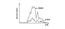
- FIG. 8 shows the amplitude (example) of muscle strength (overlapping muscle strength) data obtained by processing by the synthesis processing unit 114 of the motion assisting apparatus 10 according to the present embodiment for a certain motion of the user H, It shows the amplitude (reference example) of data obtained by root mean square (RMS) processing of the potential signal Sm.
- RMS root mean square
- the method for synthesizing the myoelectric potential signal Sm by the motion assisting device 10 according to the present embodiment since the detection error due to the difference in the installation position of the surface electrode is reduced, the inter-subject variation is also reduced, and at the time of use Calibration work is not necessary, or a very simple calibration process can be performed. Further, in the method for synthesizing the myoelectric potential signal Sm by the motion assisting device 10 according to the present embodiment, the myoelectric potential signal Sm is compared with a plurality of previously stored myoelectric potential waveforms, an envelope is obtained, and the like. Without overlapping, unit muscle strength is superimposed each time the motor unit action potential MUAP is detected. For this reason, since the motor unit action potential MUAP is superimposed before the muscle contraction of the user H occurs, the response from when the myoelectric potential signal Sm is detected until the drive command is output to the rotary actuator 21. Time can be shortened.
- the auxiliary force calculating unit 116 calculates the required auxiliary force Tq_ast based on the amplitude of the superimposing muscle force data.
- the auxiliary force calculation unit 116 uses one or a plurality of conventionally known artificial intelligence algorithms (AI) such as a support vector machine (SVM), a neural network (ANN), and a Gaussian mixture model (GMM) to perform step S20.
- AI artificial intelligence algorithms
- SVM support vector machine
- ANN neural network
- GMM Gaussian mixture model
- the superimposing muscle strength data obtained in the above is converted into the required auxiliary force Tq_ast.
- the auxiliary force calculating unit 116 predicts the required auxiliary force Tq_ast corresponding to the amplitude of the superimposing muscle force data by performing a regression calculation. This output value is a continuous value.
- the auxiliary force calculation unit 116 outputs the calculated required auxiliary force Tq_ast to the drive control unit 120.
- the auxiliary force calculation unit 116 may obtain the required auxiliary force Tq_ast based on not only the amplitude of the superimposing muscle force data obtained by the synthesis processing unit 114 but also other information. For example, information related to user H's exoskeleton joint angle, angular velocity or acceleration of joint movement, gender, age, height or weight, etc., or exoskeleton motion obtained in the past in time A signal other than the myoelectric potential signal such as a signal of the assisting force or the like may be referred to.
- the assisting force calculation unit 116 receives not only an online operation mode for receiving only the input of superimposing muscle strength data but also a signal of a desired output together with the input of superimposing muscle strength data, and the user
- An off-line training mode that causes H to perform training of the motion assisting device 10 may be executable. Further, the assisting force calculation unit 116 may execute an algorithm that enables execution of an online training mode that causes the user H to perform training of the motion assisting device 10.
- the drive control unit 120 determines the drive torque Tq_mtr of the rotary actuator 21 based on the value of the requested auxiliary force Tq_ast obtained by the signal processing unit 110 and outputs a drive command to the rotary actuator 21. For example, the drive control unit 120 may obtain the drive torque Tq_mtr of the rotary actuator 21 with reference to a map that defines the relationship between the requested auxiliary force Tq_ast and the drive torque Tq_mtr.
- the drive control unit 120 outputs a drive command to the rotation actuator 21, the rotation actuator 21 is driven with a desired rotation torque, and the operation of the user H wearing the operation assisting device 10 is assisted.
- the rotary actuator 21 is accommodated in the joint portion 20.
- the rotary actuator 21 is disposed at a position away from the joint portion 20, via a power transmission mechanism.
- the arm unit 23 may be rotated.
- the rotary actuator 21 may be accommodated in a control pack 26 provided on the back side of the waist mounting portion 13.
- it may be accommodated together with the control unit 25 in a backpack carried by the user H.
- two myoelectric potential sensors 31 and 33 are provided on the upper and lower portions of the front surface of the thigh, but may be provided on the muscles on the back side of the thigh.
- noise can be reduced by executing the process of amplifying the difference between two sensor values for all sensor values, and the measurement error of the motor unit action potential MUAP can be reduced. Can be reduced. Thereby, the assistance of the operation
- the extraction processing unit 112 extracts the motor unit action potential MUAP based on the sensor signals of the myoelectric potential sensors 31 and 33, but before extracting the motor unit action potential MUAP.
- the blind source separation (BSS) process may be performed on the myoelectric signal Sm.
- BSS blind sound source separation
- ICA independent component analysis
- filtering may be performed on the myoelectric potential signal Sm subjected to the blind sound source separation (BSS) process to further reduce noise.
- the motor unit action potential MUAP is extracted from the myoelectric potential signal Sm, and the plurality of motor unit action potentials MUAPs thus extracted are superimposed, thereby superimposing muscle strength. Data is required. Further, in the motion assisting device 10, the required assisting force Tq_ast is calculated based on the obtained overlapping muscle force data, and the driving torque Tq_mtr of the rotary actuator 21 is generated. As described above, in the motion assisting apparatus 10 according to the present embodiment, unit muscle strength is superimposed according to the extracted motor unit action potential MUAPs, so that stability against changes in signal transmission conditions between muscle fibers and surface electrodes is improved. Excellent in properties.
- the motor unit action potential MUAP is obtained without comparing the myoelectric potential signal Sm with a plurality of prestored myoelectric potential waveforms or obtaining an envelope. Whenever it is detected, unit muscle strength is superimposed. For this reason, since the motor unit action potential MUAP is superimposed before the muscle contraction of the user H occurs, the response from when the myoelectric potential signal Sm is detected until the drive command is output to the rotary actuator 21. Time can be shortened.
- the operation assistance apparatus 1 was comprised as an apparatus which assists the user's H back-and-forth movement of both legs, this invention is not limited to this example.
- the motion assisting device may be a device that assists the user H's back and forth movement of one leg.
- the joint part 20, the arm part 23, and the thigh attachment part 17 are provided only in any one of right and left.
- the movement assisting device 1 is not limited to a device that assists the front and back movement of the thigh, and may be a device that assists the calf movement around the knee joint or a device that assists the movement of the arm. There may be.
Landscapes
- Health & Medical Sciences (AREA)
- Life Sciences & Earth Sciences (AREA)
- Engineering & Computer Science (AREA)
- Animal Behavior & Ethology (AREA)
- Veterinary Medicine (AREA)
- Public Health (AREA)
- General Health & Medical Sciences (AREA)
- Surgery (AREA)
- Biophysics (AREA)
- Molecular Biology (AREA)
- Physics & Mathematics (AREA)
- Heart & Thoracic Surgery (AREA)
- Biomedical Technology (AREA)
- Pathology (AREA)
- Medical Informatics (AREA)
- Epidemiology (AREA)
- Pain & Pain Management (AREA)
- Physical Education & Sports Medicine (AREA)
- Rehabilitation Therapy (AREA)
- Robotics (AREA)
- Mechanical Engineering (AREA)
- Rehabilitation Tools (AREA)
- Manipulator (AREA)
Abstract
時間的な遅延を低減しつつ、ユーザの動作に応じて動作補助装置を適切に制御可能な動作補助装置を提供する。 動作補助装置は、ユーザの筋電位信号を検出する信号検出部と、取得された筋電位信号から運動単位活動電位を抽出する抽出処理部と、抽出されたそれぞれの運動単位活動電位の筋力を重ね合わせて要求補助力を求める合成処理部と、要求補助力に基づき、ユーザに装着された動作補助装置を駆動させるアクチュエータの駆動トルクを算出するトルク算出部と、を備える。
Description
本発明は、人体に装着される動作補助装置に関する。
近年、歩行動作や手足の曲げ伸ばし動作等の人の動作を補助する動作補助装置が知られている。動作補助装置は、人体に装着されて、ユーザの手足の動きに合わせて作動することによって、ユーザの動作を補助する。例えば、動作補助装置は、身体の関節部分に対応して配置される回転軸を中心に回動可能なアーム部材を備え、アクチュエータによってアーム部材を回転させることによって、アーム部材が固定された身体の部分の動作を補助する。かかる動作補助装置は、例えば、障害者又は高齢者だけでなく、健常者の動作を補助する装置等としても、様々な場面で使用され得る。
ここで、非特許文献1に記載されているように、人の動作は、人体の骨格筋の収縮によって実現されている。骨格筋が収縮する際、筋線維は、運動ニューロンの刺激に反応して電気的な活動を起こす。運動ニューロンと、当該運動ニューロンが神経支配する筋線維は、運動単位(MU)と呼ばれる機能的構造体と考えられている。骨格筋の電気的な活動は、皮膚の表面に電極を配置することによって観察することができる。この手法は、筋電図検査として知られており、観察された電気信号が筋電位である。筋電図検査には、皮膚の表面に配置された電極を用いて筋肉の動作を検出する表面筋電図検査(sEMG)と、筋肉や神経線維の表面又は内部に配置された電極を用いて筋肉の動作を検出する筋電図検査(EMG)とがある。
このうち、表面筋電図に基づいて行われる動作補助装置の制御として、種々の方法が知られている。筋電位信号の振幅の大きさは、動作補助装置を所望の補助力で作動させるための情報として用いられる。筋電位信号の振幅を求める方法としては、例えば、エンベロープ(包絡線)抽出処理、平均整流電流算出処理又はRMS値(二乗平均値)算出処理が用いられている。
しかしながら、表面筋電図に基づいて行われる動作補助装置の制御方法において、筋電位信号の質は、表面筋電図を検出する電極の位置に大きく依存することが知られている。また、非特許文献2に記載されているように、表面筋電図に基づいて行われる動作補助装置の制御方法は、被験者間変動が大きいことが知られている。
Campbell N. A., and J. B. Reece. Biology. 7th ed. San Francisco: Pearson, 2005. 1066-1068.
Winter D.A., Yack H.J., EMG profiles during normal human walking: stride-to-stride and inter-subject variability, Electroencephalography and Neurology, 1987.
電極の位置の制約や被験者間変動が大きいことから、筋電位信号を検出するための電極は、通常、専門スタッフによって配置され、動作補助装置の使用環境が、実質的に臨床環境に制限される。また、上記の例による筋電位信号の処理は、筋電位信号を取得してから動作補助装置が駆動されるまでの時間的な遅延を生じさせ、動作補助装置の性能が損なわれるおそれがあった。
本発明は、上記問題に鑑みてなされたものであり、本発明の目的とするところは、時間的な遅延を低減しつつ、ユーザの動作に応じて動作補助装置を適切に制御可能な、新規かつ改良された動作補助装置を提供することにある。
上記課題を解決するために、本発明のある観点によれば、ユーザの筋電位信号を検出する信号検出部と、取得された筋電位信号から運動単位活動電位を抽出する抽出処理部と、抽出されたそれぞれの運動単位活動電位の筋力を重ね合わせて要求補助力を求める合成処理部と、要求補助力に基づき、ユーザに装着された動作補助装置を駆動させるアクチュエータの駆動トルクを算出するトルク算出部と、を備えた、動作補助装置が提供される。
本発明の動作補助装置によれば、合成処理部が、筋電位信号から抽出された運動単位活動電位に対応する筋力を重ね合わせて要求補助力を求め、当該要求補助力に基づいてトルク算出部が、アクチュエータの駆動トルクを算出している。したがって、筋電位信号を検出してからアクチュエータに駆動トルクを出力するまでの時間の遅れが低減され、ユーザの動作を適切に補助可能な動作補助装置を得ることができる。また、かかる動作補助装置は、電極の設置位置等の違いによる信号伝達条件の変化に対する安定性に優れている。したがって、被験者間変動も低減することができる。
抽出処理部は、抽出した運動単位活動電位の周波数あるいは頻度の情報を抽出してもよい。
抽出処理部は、ウェーブレット変換、ウェーブレットパケット、フーリエ変換、テンプレートマッチングアルゴリズム、ファジー識別器、又は、機械学習アルゴリズムを用いて、筋電位信号から運動単位活動電位を抽出してもよい。
単位筋力は、筋電位信号の検出対象の運動単位に応じてあらかじめ設定されてもよい。
信号検出部は、運動単位上に配置された少なくとも1つの表面筋電位検出電極を含んでもよい。
以上説明したように本発明によれば、時間的な遅延を低減しつつ、ユーザの動作に応じて動作補助装置を適切に制御することができる。
以下に添付図面を参照しながら、本発明の好適な実施の形態について詳細に説明する。なお、本明細書及び図面において、実質的に同一の機能構成を有する構成要素については、同一の符号を付することにより重複説明を省略する。
<1.動作補助装置の全体構成>
まず、図1~図2を参照して、本実施形態にかかる動作補助装置10の全体構成例について説明する。図1は、動作補助装置10を装着したユーザを正面から見た図であり、図2は、動作補助装置10を装着したユーザを側方から見た図である。
まず、図1~図2を参照して、本実施形態にかかる動作補助装置10の全体構成例について説明する。図1は、動作補助装置10を装着したユーザを正面から見た図であり、図2は、動作補助装置10を装着したユーザを側方から見た図である。
本実施形態にかかる動作補助装置10は、歩行動作又は階段昇降動作等の左右の脚の前後運動の動作を補助するための装置であり、いわゆる外骨格ロボットとも呼ばれる。動作補助装置10は、腰装着部13と、大腿部装着部17と、回転アクチュエータ21と、アーム部23と、筋電位センサ31,33と、制御ユニット25とを備える。
腰装着部13は、ユーザHの腰部に装着され、固定ベルト11により固定される。腰装着部13のうち、人体の側部に位置する部分には、関節部20が設けられている。関節部20は、ユーザHの腰関節の位置に対応するように設けられる。関節部20では、アーム部23と腰装着部13とが相対的に回転可能に連結されている。
アーム部23は、関節部20から下方に延設され、アーム部23の下方側には、大腿部装着部17が設けられている。大腿部装着部17は、ユーザHの脚部のうちの大腿部に装着され、固定ベルト15により固定される。関節部20には、回転アクチュエータ21が備えられ、当該回転アクチュエータ21を駆動させることにより、関節部20を中心にアーム部23が回動する。これにより、大腿部装着部17が装着されたユーザHの大腿部の前後方向の動きが補助される。
また、動作補助装置10は、ユーザHの筋電位信号を検出するための筋電位センサ31,33を有する。本実施形態では、筋電位センサ31,33は、ユーザHの大腿部の上部及び下部にそれぞれ2個設けられた表面電極を含む。筋電位センサ31,33の表面電極は、所望の運動単位を構成する筋肉群の位置に対応するように、ユーザHの大腿部の表面に取り付けられる。例えば、筋電位センサ31,33の表面電極は、粘着シートを用いて皮膚表面に貼り付けられてもよく、他の方法により配置されてもよい。また、設けられる筋電位センサ31,33の数は特に限定されない。
腰装着部13の背中側には制御パック26が備えられる。制御パック26内には制御ユニット25が収容されている。制御ユニット25は、筋電位センサ31,33により検出される筋電位信号を取得して演算処理を行い、回転アクチュエータ21に対して駆動指令を出力する。制御ユニット25は、CPU及び記憶素子等の電子部品を備えて構成され、図示しない電気配線により筋電位センサ31,33及び回転アクチュエータ21に電気的に接続される。制御ユニット25と、筋電位センサ31,33又は回転アクチュエータ21とは、無線の通信手段によって接続されてもよい。
かかる動作補助装置10では、ユーザHの動作に伴って生成される筋電位信号が筋電位センサ31,33により検出され、制御ユニット25が当該筋電位信号を処理することによって要求補助トルクを算出する。また、制御ユニット25により、当該要求補助トルクに基づいて回転アクチュエータ21の駆動トルクが決定され、回転アクチュエータ21に送信される。これにより、回転アクチュエータ21が回転駆動され、アーム部23が回転することによって、ユーザHの脚の前後動作に対する補助力が生成される。
<2.動作補助装置の制御系の構成>
図3は、本実施形態にかかる動作補助装置10の制御系の構成例を示すブロック図である。動作補助装置10は、信号検出部としての筋電位センサ31,33と、信号処理部110と、トルク算出部としての駆動制御部120と、回転アクチュエータ21とを備えている。信号処理部110は、抽出処理部112、合成処理部114及び補助力算出部116を含む。信号処理部110は、例えばマイクロコンピュータにより構成され、当該マイクロコンピュータによるプログラムの実行により抽出処理部112、合成処理部114及び補助力算出部116の機能が実現され得る。また、駆動制御部120は、例えばマイクロコンピュータにより構成され得る。信号処理部110と駆動制御部120とは異なるマイクロコンピュータにより構成されてもよく、1つのマイクロコンピュータにより実現されてもよい。
図3は、本実施形態にかかる動作補助装置10の制御系の構成例を示すブロック図である。動作補助装置10は、信号検出部としての筋電位センサ31,33と、信号処理部110と、トルク算出部としての駆動制御部120と、回転アクチュエータ21とを備えている。信号処理部110は、抽出処理部112、合成処理部114及び補助力算出部116を含む。信号処理部110は、例えばマイクロコンピュータにより構成され、当該マイクロコンピュータによるプログラムの実行により抽出処理部112、合成処理部114及び補助力算出部116の機能が実現され得る。また、駆動制御部120は、例えばマイクロコンピュータにより構成され得る。信号処理部110と駆動制御部120とは異なるマイクロコンピュータにより構成されてもよく、1つのマイクロコンピュータにより実現されてもよい。
(2-1.回転アクチュエータ)
回転アクチュエータ21は、動作補助装置10の関節部20に設けられて、関節部20を中心に、腰装着部13に対してアーム部23を相対的に回動させる。回転アクチュエータ21は、例えば、ステッピングモータ又はブラシレスモータを用いることができる。回転アクチュエータ21は、減速機を備えてもよい。また、回転アクチュエータ21は、回転式のロータリーモータを用いたアクチュエータに限らず、リニアモータと回転機構とを備えたアクチュエータであってもよい。
回転アクチュエータ21は、動作補助装置10の関節部20に設けられて、関節部20を中心に、腰装着部13に対してアーム部23を相対的に回動させる。回転アクチュエータ21は、例えば、ステッピングモータ又はブラシレスモータを用いることができる。回転アクチュエータ21は、減速機を備えてもよい。また、回転アクチュエータ21は、回転式のロータリーモータを用いたアクチュエータに限らず、リニアモータと回転機構とを備えたアクチュエータであってもよい。
(2-2.筋電位センサ)
筋電位センサ31,33は、例えば、少なくとも1つの表面筋電位検出電極(表面電極)と、少なくとも1つのAD変換器と、少なくとも1つの増幅器とを備える。表面電極は、例えば、動作補助装置10により補助可能な動作に対応する所望の運動単位の筋肉の腹の部分に位置する皮膚の表面に貼付される。本実施形態においては、筋電位センサ31,33は、大腿の前面側の筋肉の上部及び下部に対応してそれぞれ2個貼付された表面電極を有する。表面電極は、例えば、容積伝導により伝わってくる運動単位の筋電位信号Smを皮膚の表面から導出する。具体的には、表面電極は、筋線維が発生する筋電位を検出する。表面電極は、例えば単極型、双極型又は三極型の電極であってよく、さらに、アレイ型又はマトリックス型の電極であってもよい。なお、表面電極は1個であってもよいし、3個以上であってもよい。
筋電位センサ31,33は、例えば、少なくとも1つの表面筋電位検出電極(表面電極)と、少なくとも1つのAD変換器と、少なくとも1つの増幅器とを備える。表面電極は、例えば、動作補助装置10により補助可能な動作に対応する所望の運動単位の筋肉の腹の部分に位置する皮膚の表面に貼付される。本実施形態においては、筋電位センサ31,33は、大腿の前面側の筋肉の上部及び下部に対応してそれぞれ2個貼付された表面電極を有する。表面電極は、例えば、容積伝導により伝わってくる運動単位の筋電位信号Smを皮膚の表面から導出する。具体的には、表面電極は、筋線維が発生する筋電位を検出する。表面電極は、例えば単極型、双極型又は三極型の電極であってよく、さらに、アレイ型又はマトリックス型の電極であってもよい。なお、表面電極は1個であってもよいし、3個以上であってもよい。
AD変換器は、表面電極により取得される筋電位信号Smをデジタル信号に変換する。また、増幅器は、AD変換器により変換されたデジタル信号を増幅して出力する。AD変換器及び増幅器は、皮膚表面に貼付される表面電極側に一体化されて設けられてもよく、あるいは、表面電極から筋電位信号Smを取得する制御ユニット25側に設けられてもよい。また、筋電位センサ31,33は、検出される筋電位信号Smのノイズを低減するためのフィルタを備えてもよい。フィルタは、除去したいノイズ信号の振幅に応じて、LPF(ローパスフィルタ)、HPF(ハイパスフィルタ)、BPF(バンドパスフィルタ)等の各種フィルタを適宜用いることができる。
(2-3.信号処理部)
信号処理部110は、取得した筋電位信号Smを処理し、要求補助力Tq_astを算出する。図4は、信号処理部110によって実行される要求補助力Tq_astの算出処理のフローを示している。信号処理部110のうち抽出処理部112は、筋電位センサ31,33のセンサ信号を取得し、検出された筋電位信号Smから運動単位活動電位MUAPを抽出する(ステップS10)。また、信号処理部110のうち合成処理部114は、抽出されたそれぞれの運動単位活動電位MUAPに対応する単位筋力を重ね合わせて、筋電位信号Smに対応する筋力を求める(ステップS20)。また、信号処理部110のうち補助力算出部116は、求められた筋力に基づいて、要求補助力Tq_astを算出する(ステップS30)。
信号処理部110は、取得した筋電位信号Smを処理し、要求補助力Tq_astを算出する。図4は、信号処理部110によって実行される要求補助力Tq_astの算出処理のフローを示している。信号処理部110のうち抽出処理部112は、筋電位センサ31,33のセンサ信号を取得し、検出された筋電位信号Smから運動単位活動電位MUAPを抽出する(ステップS10)。また、信号処理部110のうち合成処理部114は、抽出されたそれぞれの運動単位活動電位MUAPに対応する単位筋力を重ね合わせて、筋電位信号Smに対応する筋力を求める(ステップS20)。また、信号処理部110のうち補助力算出部116は、求められた筋力に基づいて、要求補助力Tq_astを算出する(ステップS30)。
(2-3-1.運動単位活動電位の抽出)
抽出処理部112は、ステップS10において運動単位活動電位MUAPを抽出する。これにより、筋電位センサ31,33から取得されるセンサ信号に含まれるノイズが除去されて、運動単位活動電位MUAPが抽出される。抽出処理部112は、例えば、抽出された運動単位活動電位MUAPの周波数あるいは頻度の情報を抽出してもよい。筋電位信号Smから運動単位活動電位MUAPを抽出する方法としては、例えば、ウェーブレット変換、ウェーブレットパケット、フーリエ変換、テンプレートマッチングアルゴリズム、ファジー識別器、又は、他の自己回帰モデル係数のような各種の公知の機械学習アルゴリズムが利用され得る。
抽出処理部112は、ステップS10において運動単位活動電位MUAPを抽出する。これにより、筋電位センサ31,33から取得されるセンサ信号に含まれるノイズが除去されて、運動単位活動電位MUAPが抽出される。抽出処理部112は、例えば、抽出された運動単位活動電位MUAPの周波数あるいは頻度の情報を抽出してもよい。筋電位信号Smから運動単位活動電位MUAPを抽出する方法としては、例えば、ウェーブレット変換、ウェーブレットパケット、フーリエ変換、テンプレートマッチングアルゴリズム、ファジー識別器、又は、他の自己回帰モデル係数のような各種の公知の機械学習アルゴリズムが利用され得る。
図5は、筋電位信号Smから運動単位活動電位MUAPを抽出する方法の例として、ウェーブレット変換を用いた例について説明するために示す図である。図5の最上段には筋電位センサ31,33から出力される筋電位信号Smの値が示され、図5の中段三段には異なるスケールを用いてウェーブレット変換を行う様子が示され、図5の最下段には運動単位活動電位MUAPの抽出結果が示されている。
図5に示した例では、表面電極を用いて検出され得る実際の活動電位に対応した大中小三段階のスケールを用いて筋電位信号Smから運動単位活動電位MUAPを抽出している。筋電位センサ31,33により検出される筋電位信号Smの振幅は、表面電極と筋肉との距離等に応じて異なり得るため、3つのスケールを用いて運動単位活動電位MUAPの抽出が行われる。“ウェーブレット”は、できる限り活動電位の波形に一致するように検出される。図5の例では、ハット型のウェーブレットが用いられ、各スケールのウェーブレットに近似する活動電位が抽出されている。活動電位の波形は、対象とするユーザHの動作や筋肉の位置等に応じて、あらかじめ設定される。
また、ウェーブレット係数のピーク値が所定の閾値を超えたものが、運動単位活動電位MUAPとして定義される一方、閾値を超えないものは強制的に0に置き換えられる。また、大中小いずれかのスケールにおいて、ウェーブレット係数が閾値を超えた場合には、他のスケールでMUAPが重複してカウントされないように、閾値が所定の期間、ゼロに設定される。ウェーブレット係数のピーク値の閾値は、従来公知の方法によって抽出処理部112により自動的に定義され得る。したがって、ユーザ等の手動による校正処理が不要になる。
抽出された運動単位活動電位MUAPには、時間間隔が短い(周波数が大きい)状態で検出される運動単位活動電位MUAPと、時間間隔が長い(周波数が小さい)状態で検出される運動単位活動電位MUAPとが見られる。一般に、ユーザHの動作が速い場合、すなわち、ユーザHの動作に伴う筋力が大きい場合ほど、運動単位活動電位MUAPの時間間隔は短く(周波数が大きく)なる。
(2-3-2.筋力の重ね合わせ)
合成処理部114は、ステップS20において、検出された運動単位活動電位MUAPに対応する単位筋力を重ね合わせて、筋電位信号Smに対応する筋力を求める。本実施形態にかかる動作補助装置10では、筋電位信号Smから抽出された運動単位活動電位MUAPの周波数によって、単位筋力の重ね合わせにより得られる筋力が異なり得る。つまり、ユーザHの動作が速いほど運動単位活動電位MUAPの周波数が大きくなるため、単位筋力を重ね合わせられて求められる筋力が異なることとなる。例えば、合成処理部114は、運動単位活動電位MUAPに対応する筋力の重ね合わせ処理として畳み込み演算を実行し得る。
合成処理部114は、ステップS20において、検出された運動単位活動電位MUAPに対応する単位筋力を重ね合わせて、筋電位信号Smに対応する筋力を求める。本実施形態にかかる動作補助装置10では、筋電位信号Smから抽出された運動単位活動電位MUAPの周波数によって、単位筋力の重ね合わせにより得られる筋力が異なり得る。つまり、ユーザHの動作が速いほど運動単位活動電位MUAPの周波数が大きくなるため、単位筋力を重ね合わせられて求められる筋力が異なることとなる。例えば、合成処理部114は、運動単位活動電位MUAPに対応する筋力の重ね合わせ処理として畳み込み演算を実行し得る。
図6及び図7は、運動単位活動電位MUAPに対応する筋力の畳み込み演算について説明するための模式図である。図6は、動作補助装置10の補助対象の運動単位に応じてあらかじめ設定され得る運動単位活動電位MUAPの単位筋力波形を示す。つまり、運動単位の筋肉は、運動単位活動電位MUAPごとに単位筋力波形の筋力を生成するものと仮定される。また、単位筋力波形は、ユーザHの性別又は年齢等の属性に応じて設定されてもよく、あるいは、使用に応じて学習された単位筋力により更新されてもよい。図7は、抽出された複数の運動単位活動電位MUAPsに応じて単位筋力を重ね合わせた様子を示す。
人が動作を起こす場合、最初の運動単位活動電位MUAP1を受け取った後に筋収縮が生じ、筋力が生成される。抽出された複数の運動単位活動電位MUAPsの周波数が小さい場合(図7の一点鎖線)、最初の運動単位活動電位MUAP1に対応する筋力がゼロに低下した後に、次の運動単位活動電位MUAP2’,MUAP3’・・・が受信される。つまり、ユーザHの動作が遅い場合には、複数の運動単位活動電位MUAPsの重ね合わせ処理を行ったとしても、重ね合わせ筋力の値は大きくならない。
一方、抽出された複数の運動単位活動電位MUAPsの周波数が大きい場合(図7の実線)、最初の運動単位活動電位MUAP1に対応する筋力がゼロに低下する前に、次の運動単位活動電位MUAP2に対応する筋力が重ね合わせられ、重ね合わせ筋力の値は増大する。その後も、運動単位活動電位MUAPnに対応する筋力が低下する前に、次の運動単位活動電位MUAPn+1が受信され、重ね合わせ筋力の値はゼロまで低下することがない。つまり、求められる重ね合わせ筋力は、抽出された運動単位活動電位MUAPsの周波数に依存する。このようにして、合成処理部114により、抽出された運動単位活動電位MUAPsと筋力との関係が求められる。
図8は、ユーザHのある動作に対して、本実施形態にかかる動作補助装置10の合成処理部114による処理によって得られた筋力(重ね合わせ筋力)のデータの振幅(実施例)と、筋電位信号Smを二乗平均平方根(RMS)処理して得られたデータの振幅(参考例)とを示している。RMS処理は、筋電位信号Smをフィルタリングしつつ二乗平均平方根処理を行った例が示されている。
図8に示したように、本実施形態にかかる運動単位活動電位MUAPsの重ね合わせ処理によって、従来の筋電図処理で用いられている二乗平均平方根処理の結果による特徴と類似する結果が得られていることが分かる。したがって、本実施形態にかかる動作補助装置10による筋電位信号Smの合成処理方法が有用であることが理解できる。また、本実施形態にかかる動作補助装置10による筋電位信号Smの合成処理方法では、抽出された運動単位活動電位MUAPsに応じて単位筋力が重ね合わせられるため、筋線維と表面電極との間の信号伝達条件の変化に対する安定性に優れている。
また、本実施形態にかかる動作補助装置10による筋電位信号Smの合成処理方法では、表面電極の設置位置の違いによる検出誤差が小さくなることから、被験者間変動も小さくなり、かつ、使用時の校正作業が不要になるか、あるいは、ごく簡単な校正処理とすることができる。さらに、本実施形態にかかる動作補助装置10による筋電位信号Smの合成処理方法では、筋電位信号Smを、あらかじめ記憶された複数の筋電位の波形と比較したり、包絡線を求めたり等することなく、運動単位活動電位MUAPが検出されるごとに単位筋力の重ね合わせが行われる。このため、ユーザHの筋肉の収縮が生じるより前に運動単位活動電位MUAPの重ね合わせが行われるため、筋電位信号Smが検出されてから回転アクチュエータ21に対して駆動指令を出力するまでの応答時間を短縮することができる。
(2-3-3.要求補助力の算出)
補助力算出部116は、ステップS30において、重ね合わせ筋力のデータの振幅に基づいて、要求補助力Tq_astを算出する。例えば、補助力算出部116は、サポートベクターマシン(SVM)、ニューラルネットワーク(ANN)、ガウス混合モデル(GMM)等の従来公知の1つ又は複数の人工知能アルゴリズム(AI)を用いて、ステップS20で求められた重ね合わせ筋力のデータを要求補助力Tq_astに変換する。このとき、補助力算出部116は、回帰演算を行うことで重ね合わせ筋力のデータの振幅に対応する要求補助力Tq_astを予測する。この出力値は、連続値となる。補助力算出部116は、算出した要求補助力Tq_astを駆動制御部120に出力する。
補助力算出部116は、ステップS30において、重ね合わせ筋力のデータの振幅に基づいて、要求補助力Tq_astを算出する。例えば、補助力算出部116は、サポートベクターマシン(SVM)、ニューラルネットワーク(ANN)、ガウス混合モデル(GMM)等の従来公知の1つ又は複数の人工知能アルゴリズム(AI)を用いて、ステップS20で求められた重ね合わせ筋力のデータを要求補助力Tq_astに変換する。このとき、補助力算出部116は、回帰演算を行うことで重ね合わせ筋力のデータの振幅に対応する要求補助力Tq_astを予測する。この出力値は、連続値となる。補助力算出部116は、算出した要求補助力Tq_astを駆動制御部120に出力する。
補助力算出部116は、合成処理部114によって求められた重ね合わせ筋力のデータの振幅だけでなく、さらに他の情報に基づいて要求補助力Tq_astを求めてもよい。例えば、ユーザHの外骨格の関節の角度、関節の動きの角速度又は加速度、性別、年齢、身長又は体重等のユーザH固有の情報、又は、時間的に過去に得られる外骨格の動作に関連する補助力等の信号などの筋電位信号以外の信号を参照してもよい。
なお、補助力算出部116は、重ね合わせ筋力のデータの入力だけを受信するオンラインの動作モードだけでなく、重ね合わせ筋力のデータの入力と併せて、所望の出力の信号を受信して、ユーザHに動作補助装置10の訓練を実施させるオフライン訓練モードが実行可能になっていてもよい。また、補助力算出部116は、ユーザHに動作補助装置10の訓練を実施させるオンライン訓練モードを実行可能とするアルゴリズムを実行してもよい。
(2-4.駆動制御部)
駆動制御部120は、信号処理部110により求められた要求補助力Tq_astの値に基づいて、回転アクチュエータ21の駆動トルクTq_mtrを決定し、回転アクチュエータ21に対して駆動指令を出力する。例えば、駆動制御部120は、要求補助力Tq_astと駆動トルクTq_mtrとの関係を定めたマップを参照して、回転アクチュエータ21の駆動トルクTq_mtrを求めてもよい。駆動制御部120が回転アクチュエータ21に対して駆動指令を出力することにより、回転アクチュエータ21が所望の回転トルクで駆動され、動作補助装置10を装着したユーザHの動作の補助が行われる。
駆動制御部120は、信号処理部110により求められた要求補助力Tq_astの値に基づいて、回転アクチュエータ21の駆動トルクTq_mtrを決定し、回転アクチュエータ21に対して駆動指令を出力する。例えば、駆動制御部120は、要求補助力Tq_astと駆動トルクTq_mtrとの関係を定めたマップを参照して、回転アクチュエータ21の駆動トルクTq_mtrを求めてもよい。駆動制御部120が回転アクチュエータ21に対して駆動指令を出力することにより、回転アクチュエータ21が所望の回転トルクで駆動され、動作補助装置10を装着したユーザHの動作の補助が行われる。
<3.変形例>
ここまで、本実施形態にかかる動作補助装置10の構成例について説明した。本実施形態にかかる動作補助装置10は、種々の変形が可能である。以下、動作補助装置10の変形例の幾つかを説明する。
ここまで、本実施形態にかかる動作補助装置10の構成例について説明した。本実施形態にかかる動作補助装置10は、種々の変形が可能である。以下、動作補助装置10の変形例の幾つかを説明する。
本実施形態にかかる動作補助装置10では、回転アクチュエータ21が関節部20に収容される構成となっているが、回転アクチュエータ21は関節部20から離れた位置に配置されて、動力伝達機構を介してアーム部23を回動させるものであってもよい。例えば、回転アクチュエータ21が、腰装着部13の背中側に設けられた制御パック26内に収容されてもよい。あるいは、ユーザHが背負うバックパック等に、制御ユニット25とともに収容されていてもよい。
本実施形態にかかる動作補助装置10では、筋電位センサ31,33が、大腿の前面の上部及び下部にそれぞれ2個設けられていたが、大腿の裏側の筋肉に設けられてもよい。筋電位を計測するセンサが増えるほど、2つのセンサ値の差分を増幅する処理をすべてのセンサ値に対して実行することによって、ノイズを低減させることができ、運動単位活動電位MUAPの測定誤差を少なくすることができる。これにより、動作補助装置10によるユーザHの動作のアシストを適切に実行することができる。
本実施形態にかかる動作補助装置10では、筋電位センサ31,33のセンサ信号に基づき、抽出処理部112が運動単位活動電位MUAPを抽出していたが、運動単位活動電位MUAPを抽出する前に、筋電位信号Smに対してブラインド音源分離(BSS)処理を行ってもよい。特に、1つの筋電位センサが2つの電極を備えている場合には、2つの電極の検出値の差分を取ることによってノイズを低減できるが、1つの筋電位センサが1つの電極を備えている場合にブラインド音源分離(BSS)処理を行ってノイズを除去することが有効である。ブラインド音源分離(BSS)は、独立成分分析(ICA)に基づく信号の分離処理であって、筋電位信号Smから1つの筋肉の筋電位を分離することができる。これにより、動作補助装置10によるユーザHの動作のアシストを適切に実行することができる。この場合、ブラインド音源分離(BSS)処理された筋電位信号Smに対してフィルタリングを行い、さらにノイズを低減してもよい。
<4.まとめ>
以上説明したように、本実施形態にかかる動作補助装置10では、筋電位信号Smから運動単位活動電位MUAPが抽出され、抽出された複数の運動単位活動電位MUAPsを重ね合わせることによって重ね合わせ筋力のデータが求められる。また、動作補助装置10では、求められた重ね合わせ筋力のデータに基づいて要求補助力Tq_astが算出され、回転アクチュエータ21の駆動トルクTq_mtrが生成される。このように、本実施形態にかかる動作補助装置10では、抽出された運動単位活動電位MUAPsに応じて単位筋力が重ね合わせられるため、筋線維と表面電極との間の信号伝達条件の変化に対する安定性に優れている。
以上説明したように、本実施形態にかかる動作補助装置10では、筋電位信号Smから運動単位活動電位MUAPが抽出され、抽出された複数の運動単位活動電位MUAPsを重ね合わせることによって重ね合わせ筋力のデータが求められる。また、動作補助装置10では、求められた重ね合わせ筋力のデータに基づいて要求補助力Tq_astが算出され、回転アクチュエータ21の駆動トルクTq_mtrが生成される。このように、本実施形態にかかる動作補助装置10では、抽出された運動単位活動電位MUAPsに応じて単位筋力が重ね合わせられるため、筋線維と表面電極との間の信号伝達条件の変化に対する安定性に優れている。
また、本実施形態にかかる動作補助装置10では、表面電極の設置位置の違いによる検出誤差が小さくなることから、被験者間変動も小さくなり、かつ、使用時の校正作業が不要になるか、あるいは、ごく簡単な校正処理とすることができる。さらに、本実施形態にかかる動作補助装置10では、筋電位信号Smを、あらかじめ記憶された複数の筋電位の波形と比較したり、包絡線を求めたり等することなく、運動単位活動電位MUAPが検出されるごとに単位筋力の重ね合わせが行われる。このため、ユーザHの筋肉の収縮が生じるより前に運動単位活動電位MUAPの重ね合わせが行われるため、筋電位信号Smが検出されてから回転アクチュエータ21に対して駆動指令を出力するまでの応答時間を短縮することができる。
以上、添付図面を参照しながら本発明の好適な実施形態について詳細に説明したが、本発明はかかる例に限定されない。本発明の属する技術の分野における通常の知識を有する者であれば、特許請求の範囲に記載された技術的思想の範疇内において、各種の変更例または修正例に想到し得ることは明らかであり、これらについても、当然に本発明の技術的範囲に属するものと了解される。
また、上記実施形態では、動作補助装置1が、ユーザHの両脚の前後運動を補助する装置として構成されていたが、本発明はかかる例に限定されない。例えば、動作補助装置は、ユーザHの片脚の前後運動を補助する装置であってもよい。この場合、関節部20、アーム部23及び大腿部装着部17は、左右のいずれか一方にのみ設けられる。また、動作補助装置1は、大腿部の前後運動を補助する装置に限られず、ひざ関節を中心としたふくらはぎの動作を補助する装置であってもよいし、腕の動作を補助する装置であってもよい。
Claims (6)
- ユーザの筋電位信号を検出する信号検出部と、
取得された前記筋電位信号から運動単位活動電位を抽出する抽出処理部と、
抽出されたそれぞれの前記運動単位活動電位の筋力を重ね合わせて要求補助力を求める合成処理部と、
前記要求補助力に基づき、前記ユーザに装着された動作補助装置を駆動させるアクチュエータの駆動トルクを算出するトルク算出部と、
を備えた、動作補助装置。 - 前記抽出処理部は、抽出した前記運動単位活動電位の周波数あるいは頻度の情報を抽出する、請求項1に記載の動作補助装置。
- 前記抽出処理部は、ウェーブレット変換、ウェーブレットパケット、フーリエ変換、テンプレートマッチングアルゴリズム、ファジー識別器、又は、機械学習アルゴリズムを用いて、前記筋電位信号から前記運動単位活動電位を抽出する、請求項1又は2に記載の動作補助装置。
- 前記合成処理部は、あらかじめ設定された単位筋力を重ね合わせて筋力を推定し、要求補助力を求める、請求項1~3のいずれか1項に記載の動作補助装置。
- 前記単位筋力は、前記筋電位信号の検出対象の運動単位に応じてあらかじめ設定される、請求項4に記載の動作補助装置。
- 前記信号検出部は、運動単位上に配置された少なくとも1つの表面筋電位検出電極を含む、請求項1~5のいずれか1項に記載の動作補助装置。
Applications Claiming Priority (2)
| Application Number | Priority Date | Filing Date | Title |
|---|---|---|---|
| JP2016090015 | 2016-04-28 | ||
| JP2016-090015 | 2016-04-28 |
Publications (1)
| Publication Number | Publication Date |
|---|---|
| WO2017187658A1 true WO2017187658A1 (ja) | 2017-11-02 |
Family
ID=60161472
Family Applications (1)
| Application Number | Title | Priority Date | Filing Date |
|---|---|---|---|
| PCT/JP2016/086476 Ceased WO2017187658A1 (ja) | 2016-04-28 | 2016-12-08 | 動作補助装置 |
Country Status (1)
| Country | Link |
|---|---|
| WO (1) | WO2017187658A1 (ja) |
Cited By (2)
| Publication number | Priority date | Publication date | Assignee | Title |
|---|---|---|---|---|
| CN110558979A (zh) * | 2019-09-11 | 2019-12-13 | 宁波工程学院 | 一种基于神经网络的肌肉运动单元提取方法 |
| CN115599213A (zh) * | 2022-10-21 | 2023-01-13 | 吉林大学(Cn) | 一种基于二叉树支持向量机的仿生手控制系统及方法 |
Citations (5)
| Publication number | Priority date | Publication date | Assignee | Title |
|---|---|---|---|---|
| JPH0639754A (ja) * | 1992-07-27 | 1994-02-15 | Nippon Telegr & Teleph Corp <Ntt> | ロボットハンド制御装置 |
| JP2010058250A (ja) * | 2008-09-05 | 2010-03-18 | Tokyo Institute Of Technology | 筋骨格系モデル作成装置および該方法、筋骨格系機構制御装置ならびに筋骨格系機構システム |
| JP2011025053A (ja) * | 2010-08-16 | 2011-02-10 | Univ Of Tsukuba | 装着式動作補助装置及びその制御方法 |
| JP2014008071A (ja) * | 2012-06-27 | 2014-01-20 | Univ Of Tsukuba | 発光装置及び装着式動作補助装置 |
| US20160058647A1 (en) * | 2014-08-29 | 2016-03-03 | Conor J. MADDRY | Pneumatic electromyographic exoskeleton |
-
2016
- 2016-12-08 WO PCT/JP2016/086476 patent/WO2017187658A1/ja not_active Ceased
Patent Citations (5)
| Publication number | Priority date | Publication date | Assignee | Title |
|---|---|---|---|---|
| JPH0639754A (ja) * | 1992-07-27 | 1994-02-15 | Nippon Telegr & Teleph Corp <Ntt> | ロボットハンド制御装置 |
| JP2010058250A (ja) * | 2008-09-05 | 2010-03-18 | Tokyo Institute Of Technology | 筋骨格系モデル作成装置および該方法、筋骨格系機構制御装置ならびに筋骨格系機構システム |
| JP2011025053A (ja) * | 2010-08-16 | 2011-02-10 | Univ Of Tsukuba | 装着式動作補助装置及びその制御方法 |
| JP2014008071A (ja) * | 2012-06-27 | 2014-01-20 | Univ Of Tsukuba | 発光装置及び装着式動作補助装置 |
| US20160058647A1 (en) * | 2014-08-29 | 2016-03-03 | Conor J. MADDRY | Pneumatic electromyographic exoskeleton |
Cited By (2)
| Publication number | Priority date | Publication date | Assignee | Title |
|---|---|---|---|---|
| CN110558979A (zh) * | 2019-09-11 | 2019-12-13 | 宁波工程学院 | 一种基于神经网络的肌肉运动单元提取方法 |
| CN115599213A (zh) * | 2022-10-21 | 2023-01-13 | 吉林大学(Cn) | 一种基于二叉树支持向量机的仿生手控制系统及方法 |
Similar Documents
| Publication | Publication Date | Title |
|---|---|---|
| CN110355761B (zh) | 一种基于关节刚度和肌肉疲劳的康复机器人控制方法 | |
| US11883175B2 (en) | Paretic limb rehabilitation methods and systems | |
| US10143613B2 (en) | Step counter, step assist device, and computer-readable medium having stored thereon a step count program | |
| JP6759496B2 (ja) | 脳波パターン分類装置、脳波パターン分類方法、脳波パターン分類プログラムおよびニューロフィードバックシステム | |
| Joshi et al. | Classification of gait phases from lower limb EMG: Application to exoskeleton orthosis | |
| CN113058157B (zh) | 多信号融合的反馈式功能性电刺激系统 | |
| Zhang et al. | A dual-modal approach using electromyography and sonomyography improves prediction of dynamic ankle movement: A case study | |
| JP6340528B2 (ja) | Bmi運動補助装置 | |
| CN110652299B (zh) | 面向下肢软质外骨骼的多源传感信息融合系统 | |
| JP7477309B2 (ja) | 生体信号が表す情報を識別するためのシステム | |
| Meng et al. | An EMG-based force prediction and control approach for robot-assisted lower limb rehabilitation | |
| Biao et al. | Design and control of a flexible exoskeleton to generate a natural full gait for lower-limb rehabilitation | |
| CN114569144A (zh) | 一种基于肌电-惯性传感的膝关节腱反射状态评估方法 | |
| Félix et al. | Electronic design and validation of powered knee orthosis system embedded with wearable sensors | |
| WO2017187658A1 (ja) | 動作補助装置 | |
| Krasin et al. | EMG based elbow joint powered exoskeleton for biceps brachii strength augmentation | |
| JP2018134724A (ja) | 動作推定装置及び動作補助装置 | |
| Bhardwaj et al. | Electromyography in physical rehabilitation: a review | |
| KR20200094678A (ko) | 웨어러블 보행 보조 로봇 제어 장치 및 방법 | |
| CN115670481A (zh) | 意识关联康复机器臂运动意愿提取及协同控制方法 | |
| CN117398264B (zh) | 一种可自动切换主动控制模式的下肢康复系统及控制方法 | |
| JP2016054994A (ja) | 運動推定装置、及び運動推定方法 | |
| de Oliveira et al. | Effort estimation in robot-aided training with a neural network | |
| Ding et al. | Real-time Human Motion Intention Recognition for Powered Wearable Hip Exoskeleton using LSTM Networks | |
| Bhardwaj et al. | Onset difference between vastus lateralis and knee extension during sit to stand task |
Legal Events
| Date | Code | Title | Description |
|---|---|---|---|
| NENP | Non-entry into the national phase |
Ref country code: DE |
|
| 121 | Ep: the epo has been informed by wipo that ep was designated in this application |
Ref document number: 16900528 Country of ref document: EP Kind code of ref document: A1 |
|
| 122 | Ep: pct application non-entry in european phase |
Ref document number: 16900528 Country of ref document: EP Kind code of ref document: A1 |
|
| NENP | Non-entry into the national phase |
Ref country code: JP |