WO2017187642A1 - 表示処理プログラム、フロー出力プログラム、表示処理方法、フロー出力方法、表示処理システムおよびフロー出力システム - Google Patents
表示処理プログラム、フロー出力プログラム、表示処理方法、フロー出力方法、表示処理システムおよびフロー出力システム Download PDFInfo
- Publication number
- WO2017187642A1 WO2017187642A1 PCT/JP2016/063502 JP2016063502W WO2017187642A1 WO 2017187642 A1 WO2017187642 A1 WO 2017187642A1 JP 2016063502 W JP2016063502 W JP 2016063502W WO 2017187642 A1 WO2017187642 A1 WO 2017187642A1
- Authority
- WO
- WIPO (PCT)
- Prior art keywords
- manufacturing
- last
- product
- manufacturing facilities
- facilities
- Prior art date
- Legal status (The legal status is an assumption and is not a legal conclusion. Google has not performed a legal analysis and makes no representation as to the accuracy of the status listed.)
- Ceased
Links
Images
















Classifications
-
- G—PHYSICS
- G05—CONTROLLING; REGULATING
- G05B—CONTROL OR REGULATING SYSTEMS IN GENERAL; FUNCTIONAL ELEMENTS OF SUCH SYSTEMS; MONITORING OR TESTING ARRANGEMENTS FOR SUCH SYSTEMS OR ELEMENTS
- G05B19/00—Program-control systems
- G05B19/02—Program-control systems electric
- G05B19/418—Total factory control, i.e. centrally controlling a plurality of machines, e.g. direct or distributed numerical control [DNC], flexible manufacturing systems [FMS], integrated manufacturing systems [IMS] or computer integrated manufacturing [CIM]
-
- G—PHYSICS
- G06—COMPUTING OR CALCULATING; COUNTING
- G06Q—INFORMATION AND COMMUNICATION TECHNOLOGY [ICT] SPECIALLY ADAPTED FOR ADMINISTRATIVE, COMMERCIAL, FINANCIAL, MANAGERIAL OR SUPERVISORY PURPOSES; SYSTEMS OR METHODS SPECIALLY ADAPTED FOR ADMINISTRATIVE, COMMERCIAL, FINANCIAL, MANAGERIAL OR SUPERVISORY PURPOSES, NOT OTHERWISE PROVIDED FOR
- G06Q10/00—Administration; Management
- G06Q10/06—Resources, workflows, human or project management; Enterprise or organisation planning; Enterprise or organisation modelling
-
- G—PHYSICS
- G06—COMPUTING OR CALCULATING; COUNTING
- G06Q—INFORMATION AND COMMUNICATION TECHNOLOGY [ICT] SPECIALLY ADAPTED FOR ADMINISTRATIVE, COMMERCIAL, FINANCIAL, MANAGERIAL OR SUPERVISORY PURPOSES; SYSTEMS OR METHODS SPECIALLY ADAPTED FOR ADMINISTRATIVE, COMMERCIAL, FINANCIAL, MANAGERIAL OR SUPERVISORY PURPOSES, NOT OTHERWISE PROVIDED FOR
- G06Q50/00—Information and communication technology [ICT] specially adapted for implementation of business processes of specific business sectors, e.g. utilities or tourism
- G06Q50/04—Manufacturing
-
- Y—GENERAL TAGGING OF NEW TECHNOLOGICAL DEVELOPMENTS; GENERAL TAGGING OF CROSS-SECTIONAL TECHNOLOGIES SPANNING OVER SEVERAL SECTIONS OF THE IPC; TECHNICAL SUBJECTS COVERED BY FORMER USPC CROSS-REFERENCE ART COLLECTIONS [XRACs] AND DIGESTS
- Y02—TECHNOLOGIES OR APPLICATIONS FOR MITIGATION OR ADAPTATION AGAINST CLIMATE CHANGE
- Y02P—CLIMATE CHANGE MITIGATION TECHNOLOGIES IN THE PRODUCTION OR PROCESSING OF GOODS
- Y02P90/00—Enabling technologies with a potential contribution to greenhouse gas [GHG] emissions mitigation
- Y02P90/02—Total factory control, e.g. smart factories, flexible manufacturing systems [FMS] or integrated manufacturing systems [IMS]
-
- Y—GENERAL TAGGING OF NEW TECHNOLOGICAL DEVELOPMENTS; GENERAL TAGGING OF CROSS-SECTIONAL TECHNOLOGIES SPANNING OVER SEVERAL SECTIONS OF THE IPC; TECHNICAL SUBJECTS COVERED BY FORMER USPC CROSS-REFERENCE ART COLLECTIONS [XRACs] AND DIGESTS
- Y02—TECHNOLOGIES OR APPLICATIONS FOR MITIGATION OR ADAPTATION AGAINST CLIMATE CHANGE
- Y02P—CLIMATE CHANGE MITIGATION TECHNOLOGIES IN THE PRODUCTION OR PROCESSING OF GOODS
- Y02P90/00—Enabling technologies with a potential contribution to greenhouse gas [GHG] emissions mitigation
- Y02P90/30—Computing systems specially adapted for manufacturing
Definitions
- the present invention relates to a display processing program, a flow output program, a display processing method, a flow output method, a display processing system, and a flow output system.
- Data related to corporate activities is accumulated and used.
- data such as an operation log of a manufacturing apparatus in a product manufacturing line is accumulated and used to improve a production process.
- it has been proposed to estimate a fundamental factor based on a causal relationship from among a wide variety of factors for an abnormality occurring in a production line.
- the present invention provides a display processing program, a flow output program, a display processing method, a flow output method, a display processing system, and a flow output system that can generate a flow diagram according to a product flow.
- the display processing program is configured to identify the identification information and the processing start time of the product input to the plurality of manufacturing facilities or the identification of the products discharged from the plurality of manufacturing facilities from each of the plurality of manufacturing facilities.
- the display processing program specifies, based on the acquired log information, the last manufacturing facility that lastly started processing or completed the last processing with respect to identification information of the same product among the plurality of manufacturing facilities. Have the computer execute the process.
- the display processing program causes the computer to execute a process of identifying the manufacturing facility through which the product has passed in order from the last manufacturing facility.
- the display processing program arranges a symbol corresponding to the manufacturing facility through which the specified product has passed in the reverse order of the order, and arranges and displays a symbol corresponding to the last manufacturing facility in the final stage on the computer. Let it run.
- a flow diagram corresponding to the product flow can be generated.
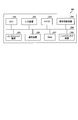
- FIG. 1 is a block diagram illustrating an example of the configuration of the display processing system according to the first embodiment.
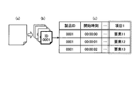
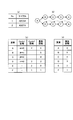
- FIG. 2 is a diagram illustrating an example of the manufacturing data storage unit.
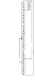
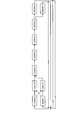
- FIG. 3 is a diagram illustrating an example of a conventional flowchart.
- FIG. 4 is a diagram illustrating an example of a conventional flowchart.
- FIG. 5 is a diagram illustrating an example of a conventional flowchart.
- FIG. 6 is a diagram illustrating an example of a conventional flowchart.
- FIG. 7 is a diagram illustrating a specific example of the start element or the end element.
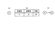
- FIG. 8 is a diagram illustrating an example of specifying the context of each element.
- FIG. 9 is a diagram illustrating an example of specifying the context of each element.
- FIG. 1 is a block diagram illustrating an example of the configuration of the display processing system according to the first embodiment.
- FIG. 2 is a diagram illustrating an example of the manufacturing data storage unit.
- FIG. 3 is a
- FIG. 10 is a diagram illustrating an example of specifying the context of each element.
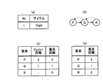
- FIG. 11 is a diagram illustrating an example of assembly of a process cycle.
- FIG. 12 is a diagram illustrating an example of assembly of process cycles.
- FIG. 13 is a diagram illustrating an example of specifying the order.
- FIG. 14 is a diagram illustrating an example of a display screen.
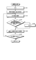
- FIG. 15 is a flowchart illustrating an example of display processing according to the first embodiment.
- FIG. 16 is a block diagram illustrating an example of the configuration of the flow output system according to the second embodiment.
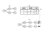
- FIG. 17 is a diagram illustrating another example of assembly of process cycles.
- FIG. 18 is a diagram illustrating another example of assembly of process cycles.
- FIG. 19 is a diagram illustrating another example of specifying the order.
- FIG. 11 is a diagram illustrating an example of assembly of a process cycle.
- FIG. 12 is a diagram illustrating an example of assembly of process cycles.
- FIG. 13 is
- FIG. 20 is a diagram illustrating another example of specifying the order.
- FIG. 21 is a diagram illustrating an example of flow diagram generation data.
- FIG. 22 is a diagram illustrating an example of a flowchart.
- FIG. 23 is a diagram illustrating an example of flow diagram generation data after rearrangement.
- FIG. 24 is a diagram illustrating an example of a flowchart after rearrangement.
- FIG. 25 is a diagram illustrating another example of the flow diagram generation data.
- FIG. 26 is a diagram illustrating another example of the flowchart.
- FIG. 27 is a diagram illustrating another example of the flow diagram generation data after rearrangement.
- FIG. 28 is a diagram illustrating another example of the flowchart after rearrangement.
- FIG. 21 is a diagram illustrating another example of specifying the order.
- FIG. 21 is a diagram illustrating an example of flow diagram generation data.
- FIG. 22 is a diagram illustrating an example of a flowchart.
- FIG. 23 is
- FIG. 29 is a diagram illustrating another example of the flow diagram generation data after rearrangement.
- FIG. 30 is a diagram illustrating another example of the flowchart after rearrangement.
- FIG. 31 is a flowchart illustrating an example of a flow output process according to the second embodiment.
- FIG. 32 is a flowchart illustrating an example of the X value calculation process.
- FIG. 33 is a flowchart illustrating an example of a Y value calculation process.
- FIG. 34 is a diagram illustrating an example of a computer that executes a display processing program or a flow output program.
- FIG. 1 is a block diagram illustrating an example of the configuration of the display processing system according to the first embodiment.
- a display processing system 1 illustrated in FIG. 1 includes an information processing apparatus 100.
- the display processing system 1 may include, for example, a control apparatus for each manufacturing process, a control apparatus for machine tools, various test apparatuses such as a temperature test, and the like.
- Production data that is, production data can be acquired.
- the display processing system 1 may also include a manager terminal device.
- the information processing apparatus 100 and various apparatuses are connected to each other via a network (not shown) so as to communicate with each other.
- a network not shown
- the information processing apparatus 100 of the display processing system 1 shown in FIG. 1 discharges from each of a plurality of manufacturing facilities, identification information and processing start times of products input to the plurality of manufacturing facilities, or the plurality of manufacturing facilities.
- Log information including the identification information of the processed product and the processing end time is acquired.
- the information processing apparatus 100 identifies the last manufacturing facility that has last started processing or completed the last processing for the identification information of the same product among the plurality of manufacturing facilities.
- the information processing apparatus 100 identifies the manufacturing facility through which the product has passed in order from the last manufacturing facility.
- the information processing apparatus 100 arranges and displays the symbols corresponding to the manufacturing facilities through which the identified product has passed in the reverse order of the retroactive order, and arranges and displays the symbols corresponding to the last manufacturing facility in the last stage. Thereby, the information processing apparatus 100 can generate a flow diagram according to the product flow.
- the information processing apparatus 100 includes a communication unit 110, a display unit 111, an operation unit 112, a storage unit 120, and a control unit 130.
- the information processing apparatus 100 may include various functional units included in known computers, for example, functional units such as various input devices and audio output devices, in addition to the functional units illustrated in FIG.
- a stationary personal computer can be employed as an example of the information processing apparatus 100.
- the information processing apparatus 100 not only the stationary personal computer but also a portable personal computer can be adopted as the information processing apparatus 100.
- the information processing apparatus 100 may employ, for example, a tablet terminal as a portable terminal.
- the communication unit 110 is realized by, for example, a NIC (Network Interface Card).
- the communication unit 110 is a communication interface that is wired or wirelessly connected to various devices via a network (not shown), and manages information communication with the various devices.
- the communication unit 110 receives manufacturing data from various devices.
- the communication unit 110 outputs the received manufacturing data to the control unit 130.
- the display unit 111 is a display device for displaying various information.
- the display unit 111 is realized by, for example, a liquid crystal display as a display device.
- the display unit 111 displays various screens such as a display screen input from the control unit 130.
- the operation unit 112 is an input device that accepts various operations from the administrator of the display processing system 1.
- the operation unit 112 is realized by, for example, a keyboard or a mouse as an input device.
- the operation unit 112 outputs an operation input by the administrator to the control unit 130 as operation information.
- the operation unit 112 may be realized by a touch panel or the like as an input device, and the display device of the display unit 111 and the input device of the operation unit 112 may be integrated.
- the storage unit 120 is realized by, for example, a semiconductor memory element such as a RAM (Random Access Memory) or a flash memory, or a storage device such as a hard disk or an optical disk.
- the storage unit 120 includes a manufacturing data storage unit 121.
- the storage unit 120 stores information used for processing in the control unit 130.
- the manufacturing data storage unit 121 stores event-type manufacturing data in which various types of information regarding manufactured products are associated with time information.
- FIG. 2 is a diagram illustrating an example of the manufacturing data storage unit. As illustrated in FIG. 2, the manufacturing data storage unit 121 includes items such as “DateTime”, “EventType”, “Worker”, “Place”, “Machine”, “Process”, and “Product”. The manufacturing data storage unit 121 stores, for example, one record for each event.
- “DateTime” is information indicating the date and time when the event occurred.
- EventType is information indicating the type of event.
- “Worker” is identification information for identifying a worker in charge of the manufacturing process.
- “Place” is identification information for identifying a place where a production line facility where an event has occurred is installed.
- “Machine” is identification information for identifying a production line facility where an event has occurred.
- “Process” is identification information for identifying a manufacturing process in which an event has occurred.
- “Product” is identification information for identifying a manufactured product in which an event has occurred, that is, a product.
- the manufacturing data storage unit 121 identifies the identification information and the processing start time of the product input to the plurality of manufacturing facilities or manufacturing processes from each of the plurality of manufacturing facilities or manufacturing processes, or the plurality of manufacturing facilities or manufacturing processes.
- Log information including the identification information of the product discharged from the process and the processing end time is stored.
- the manufacturing equipment, the manufacturing process, and the manufacturing position may be collectively expressed as elements.
- control unit 130 executes, for example, a program stored in an internal storage device using a RAM as a work area by a CPU (Central Processing Unit), an MPU (Micro Processing Unit), or the like. Is realized.
- the control unit 130 may be realized by an integrated circuit such as ASIC (Application Specific Integrated Circuit) or FPGA (Field Programmable Gate Array).
- the control unit 130 includes an acquisition unit 131, a first specification unit 132, a second specification unit 133, and a display control unit 134, and realizes or executes functions and operations of information processing described below.
- the internal configuration of the control unit 130 is not limited to the configuration illustrated in FIG. 1, and may be another configuration as long as the information processing described below is performed.
- the line segment corresponding to each manufactured product is also expressed as a trace graph, and the entire graph including the time axis of each manufacturing process and the trace graph corresponding to each manufactured product is also expressed as a timeline graph.
- the acquisition unit 131 receives and acquires manufacturing data from various devices (not shown) via the communication unit 110.
- the acquired manufacturing data includes the identification information and processing start time of the product put into the plurality of elements from each of the plurality of elements, or the identification information and processing end time of the product discharged from the plurality of elements. .
- the acquisition unit 131 stores the acquired manufacturing data in the manufacturing data storage unit 121. That is, the acquisition unit 131 accumulates and stores manufacturing data received from various devices (not shown) in the manufacturing data storage unit 121 as one record for each event.
- the first specifying unit 132 when receiving an instruction to display a graph from the user of the display processing system 1, the first specifying unit 132 reads manufacturing data, that is, log information from the manufacturing data storage unit 121. Based on the read log information, the first specifying unit 132 starts processing for the identification information of the same product among a plurality of manufacturing facilities or manufacturing processes first or last, or completes the first or last processing. Identify the first or last manufacturing facility or process. Or the 1st specific
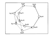
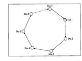
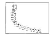
- FIGS. 3 to 6 are diagrams showing an example of a conventional flowchart.
- the flow chart shown in FIG. 3 is a conventional flow chart in the case where the manufacturing equipment pays attention to the same manufacturing equipment many times and there are a plurality of the same kind of manufacturing equipment.
- the flowchart shown in FIG. 4 is a conventional flowchart in the case where the product passes through the same equipment position many times, paying attention to the equipment position.
- the flow diagram loops so it is difficult to use as the other axis of the timeline graph.
- the flowcharts shown in FIGS. 5 and 6 are conventional flowcharts when attention is paid to the manufacturing process. 5 and 6 includes repetition of the same manufacturing process.
- FIG. 7 is a diagram illustrating a specific example of the start element or the end element.
- the first specifying unit 132 divides the log information shown in FIG. 7A into product ID units.
- the first specifying unit 132 extracts log information of a certain product ID, acquires a log with the earliest processing start time, and stores the determination target item element as a start element candidate. The information is temporarily stored in the unit 120.
- the first specifying unit 132 may acquire a log with the latest processing start time and store the element of the determination target item as an end element candidate. Further, the first specifying unit 132 may use the process end time instead of the process start time.
- the first specifying unit 132 performs the process shown in FIG. 7C on all product IDs included in the log information, so that the storage unit 120 stores the same number of elements as the unique number of product IDs. Has been. As shown in FIG. 7D, the first specifying unit 132 counts the number of appearances of each element, and specifies the element with the highest number of appearances as the start element. In the example of FIG. 7D, the first specifying unit 132 specifies “element 11” as the start element because “element 11” has 75 cases and has the highest number of appearances. In addition, the 1st specific
- the first specifying unit 132 may specify an element having a certain level or more as the start element with respect to the number of appearances. For example, when the first specifying unit 132 specifies start elements using expected values, assuming that the total results in FIG. 7C are 100 in total, and that there are six types of “item 1” elements, The expected value that a certain element is counted is 100 / 6 ⁇ 16.7. At this time, referring to FIG. 7D, since there are two elements “appearance 11” and “element 16” having the number of appearances exceeding the expected value, the first specifying unit 132 determines these two elements. Specify the starting element. The first specifying unit 132 outputs the specified start element or end element to the second specifying unit 133.
- the second specifying unit 133 specifies the elements through which the product has passed in order from the last element.
- the second specifying unit 133 executes processes such as specifying the context of each element, assembling a process cycle, and specifying the order in order to specify the element through which the product has passed.
- the second identifying unit 133 first identifies the context of each element.
- the second specifying unit 133 divides the log information shown in FIG. 8A into product ID units as shown in FIG. 8B.
- the second specifying unit 133 takes out log information of a certain product ID, and sorts the logs using the processing start time as a key. Further, the second specifying unit 133 takes out the element string of the item to be determined, as indicated by the dotted line in FIG.
- the second specifying unit 133 generates a combination list shown in FIG. 9B from the element sequence shown in FIG.
- the second specifying unit 133 represents (Y [i], Y [i + 1]) (1 ⁇ i ⁇ n ⁇ 1), where Y represents the element string, n represents the number of elements, and Y [i] represents each element.
- Generate a combination list That is, the generated combination list indicates the relationship of [previous element, subsequent element] of each element. If there is no subsequent element, “-” is assumed.
- the second specifying unit 133 generates a combination list for all product IDs in the log information, and combines the obtained combination lists into one.
- the second specifying unit 133 aggregates the combined combination list shown in FIG. 10A with [previous element + rear element] as a key, and generates the aggregate list shown in FIG. 10B in which the number of cases for each key is aggregated. To do.
- the number of cases is set as a weight representing a contextual relationship.
- the second specifying unit 133 may delete a key having a weight smaller than a certain level from the total list.
- the second specifying unit 133 assembles a process cycle.
- assembly of the process cycle will be described with reference to FIGS. 11 and 12.
- 11 and 12 are diagrams illustrating an example of assembly of process cycles.
- the second specifying unit 133 sets the input start element or end element (element “P”) as a process cycle having a length “1” and a weight “0”.
- the second specifying unit 133 selects an element subsequent to the last element of the process cycle currently being generated based on the total list.
- “Q” which is the rear element of the line having “P” as the front element in FIG. 11B, is selected.
- the second specifying unit 133 arranges the element “Q” after the element “P” and extends the process cycle.
- the second specifying unit 133 repeatedly selects and arranges the elements shown in FIGS. 11B and 11C, and as shown in FIG. 12A, processes “P”, “Q”, and “R” are performed. Extend the cycle. When the element “P” that is the start element appears in the subsequent element, the second specifying unit 133 adds the element “P” to the process cycle, and ends the extension of the subsequent process cycle. Further, as shown in FIG. 12B, the second specifying unit 133, when there is no element following the element “R” as the final element in the rear element of the aggregation list, that is, when the rear element is “ ⁇ ” Ends the process cycle at element “R” as shown in FIG.
- the second specifying unit 133 may set the weight of each process cycle based on the weight of the aggregation list. In addition, when the end element is used, the second specifying unit 133 reverses the direction of extending the process cycle in the above-described processing.
- FIG. 13 is a diagram illustrating an example of specifying the order.
- the second specifying unit 133 calculates the distance from the element of the final process of the process cycle based on the assembled process cycle list shown in FIG. In the following description, the distance from the last process element of the process cycle is expressed as the longest distance. That is, since the product always passes through the final process and is sent out of the factory, the second specifying unit 133 calculates the longest distance in order to specify the element in order from the element of the final process. In the example of FIG.
- the second specifying unit 133 sets the longest length from the element “R” for “Cycle 1” that goes back to the element “Q” and the element “P” in order from the element “R” that is the last element. Calculate the distance.
- FIG. 13C shows the calculation of the longest distance in a tabular form.
- the second specifying unit 133 specifies the arrangement order of the elements by sorting in descending order of the longest distance as shown in FIG. That is, the second specifying unit 133 specifies the order of the elements “P”, the element “Q”, and the element “R” as the arrangement order of the elements. That is, the second specifying unit 133 specifies the reverse order and the reverse order from the last process element as the element arrangement order.
- the second specifying unit 133 may exclude a process cycle having an extremely small process cycle weight in specifying the order.
- the second specifying unit 133 outputs the specified element order to the display control unit 134.
- the display control unit 134 When the element order is input from the second specifying unit 133, the display control unit 134 generates, for example, a display screen including a graph in which symbols of each element are arranged on the horizontal axis of the timeline graph. That is, the display control unit 134 arranges the symbols corresponding to the elements through which the specified product has passed in the reverse order from the elements of the last process, and arranges the symbol corresponding to the last element in the last stage. indicate. The display control unit 134 causes the display unit 111 to display the generated display screen.
- FIG. 14 is a diagram illustrating an example of a display screen.
- the display screen 21 shown in FIG. 14 includes a horizontal axis column 22 in which symbols corresponding to elements are arranged, and a graph column 23 in which trace graphs corresponding to each product are drawn.
- symbols corresponding to the element “P”, the element “Q”, and the element “R” are arranged in order from the left side that is upstream of the process. That is, in the horizontal axis column 22, a flow diagram corresponding to the product flow is drawn.
- the element “R” is the last element in the final stage.
- a trace graph 24 corresponding to a certain product is drawn via the element “P”, the element “Q”, and the element “R”.
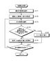
- FIG. 15 is a flowchart illustrating an example of display processing according to the first embodiment.
- the acquisition unit 131 of the information processing apparatus 100 receives and acquires manufacturing data from various devices (not shown) (step S1).
- the acquisition unit 131 stores the acquired manufacturing data in the manufacturing data storage unit 121.
- the first specifying unit 132 when receiving an instruction to display a graph from the user of the display processing system 1, the first specifying unit 132 reads manufacturing data, that is, log information from the manufacturing data storage unit 121. The first specifying unit 132 counts the number of appearances of each element based on the log information. The first specifying unit 132 specifies a start element or an end element based on the number of appearances of each element (step S2). The first specifying unit 132 outputs the specified start element or end element to the second specifying unit 133.
- manufacturing data that is, log information from the manufacturing data storage unit 121.
- the first specifying unit 132 counts the number of appearances of each element based on the log information.
- the first specifying unit 132 specifies a start element or an end element based on the number of appearances of each element (step S2).
- the first specifying unit 132 outputs the specified start element or end element to the second specifying unit 133.
- the second specifying unit 133 sets [previous element + rear element] as a key based on the input start element or end element and log information.
- the total list is generated, and the context of each element is specified (step S3).
- the second specifying unit 133 assembles a process cycle based on the input start element or end element and the summary list (step S4).
- the second specifying unit 133 calculates the longest distance based on the assembled process cycle list.
- the second specifying unit 133 specifies the order of elements by sorting the longest distances in descending order (step S5).
- the second specifying unit 133 outputs the specified element order to the display control unit 134.
- the display control unit 134 arranges symbols corresponding to the respective elements on the horizontal axis of the graph (step S6).
- the display control unit 134 generates a display screen including a graph.
- the display control unit 134 displays the generated display screen, that is, a graph on the display unit 111 (step S7).
- the information processing apparatus 100 can generate a flow diagram according to the product flow.
- the information processing apparatus 100 identifies the identification information and the processing start time of the product input to the plurality of manufacturing facilities, or the identification of the product discharged from the plurality of manufacturing facilities, from each of the plurality of manufacturing facilities. Get log information including information and processing end time.
- the information processing apparatus 100 identifies the last manufacturing facility that has started processing or completed the last processing for the identification information of the same product among the plurality of manufacturing facilities based on the acquired log information. To do. Further, the information processing apparatus 100 identifies the manufacturing facility through which the product has passed in order from the last manufacturing facility.
- the information processing apparatus 100 arranges and displays symbols corresponding to the manufacturing facilities through which the specified product has passed in the reverse order of the specified order, and arranges and displays the symbols corresponding to the last manufacturing facility in the final stage. As a result, a flow diagram corresponding to the product flow can be generated.
- the information processing apparatus 100 includes, from each of a plurality of manufacturing processes, identification information of products input to the plurality of manufacturing processes and processing start times, or identification information of products discharged from the plurality of manufacturing processes. Get log information including processing end time.
- the information processing apparatus 100 identifies the last manufacturing process that has started processing last or completed the last processing for the identification information of the same product among a plurality of manufacturing processes based on the acquired log information. To do. Further, the information processing apparatus 100 specifies the manufacturing process through which the product has passed in order from the last manufacturing process. Further, the information processing apparatus 100 arranges and displays symbols corresponding to the manufacturing process through which the specified product has passed in the reverse order to the specified order, and arranges and displays the symbol corresponding to the last manufacturing process in the final stage. As a result, a flow diagram corresponding to the product flow can be generated.
- the information processing apparatus 100 acquires log information including identification information and times of products that have moved to the plurality of manufacturing positions from each of the plurality of manufacturing positions. Moreover, the information processing apparatus 100 specifies the last manufacturing position which moved last about the identification information of the same product among several manufacturing positions based on the acquired log information. In addition, the information processing apparatus 100 specifies the manufacturing position through which the product has passed in order from the last manufacturing position. Further, the information processing apparatus 100 arranges and displays symbols corresponding to the manufacturing positions through which the specified product has passed in the reverse order of the specified order, and arranges and displays the symbols corresponding to the last manufacturing position in the final stage. As a result, a flow diagram corresponding to the product flow can be generated.
- FIG. 16 is a block diagram illustrating an example of the configuration of the flow output system according to the second embodiment.
- the same components as those of the display processing system 1 according to the first embodiment are denoted by the same reference numerals, and the description of the overlapping components and operations is omitted.
- the control unit 230 of the information processing device 200 in the flow output system 2 of the second embodiment is replaced with the second specifying unit 133 and the display control unit 134 as compared with the control unit 130 of the information processing device 100 of the first embodiment.
- a second specifying unit 233 and a display control unit 234 are included.
- the acquisition unit 131 includes at least one of individual product information and a start time and an end time of a product manufacturing process in each of a plurality of manufacturing facilities that perform manufacturing processes on the product. Get log information including and.
- specification part 132 specifies the last manufacturing equipment which performs the last manufacturing process to a product among several manufacturing equipment based on the acquired log information.
- the second specifying unit 233 executes the same processing as the processing of specifying the context of each element, assembling process cycles, and specifying the order in the second specifying unit 133 of the first embodiment.
- the specific process of the context of each element is the same as that of the first embodiment, the description thereof is omitted. Further, the assembly of the process cycle and the specific processing of the order will be described mainly with respect to differences from the first embodiment.
- the second specifying unit 233 sets the input start element or end element (element “A”) as a process cycle having a length “1” and a weight “0”.
- the second specifying unit 233 selects an element subsequent to the last element of the currently generated process cycle based on the total list.
- “B” and “D” which are the rear elements of the row having “A” as the front element in FIG. 17B are selected.
- the second specifying unit 233 extends the process cycle by arranging the element “B” and the element “D” after the element “A”. That is, in FIG. 17C, there are two process cycles.
- the second specifying unit 233 repeatedly selects and arranges the elements shown in FIGS. 17B and 17C, and as shown in FIG. 18A, the processes of the elements “A”, “B”, and “C” are performed. Extend the cycle and process cycles of elements “A”, “D”, and “E”. As shown in the row 31 of FIG. 18B, when the element “A” that is the start element appears in the rear element, the second specifying unit 233 changes the element “A” as shown in FIG. 18C. In addition to the process cycle, the extension of the subsequent process cycle is terminated. In addition, as illustrated in FIG. 18C, the second specifying unit 233 continues the process when the rear element is “F”.
- the second specifying unit 233 ends the process cycle at the final element when there is no element following the final element in the rear element of the tabulation list, that is, when the rear element is “ ⁇ ”. Note that the second identification unit 233 may set the weight of each process cycle based on the weight of the aggregation list.
- the second specifying unit 233 specifies the order.
- the specification of the order will be described with reference to FIGS. 19 and 20.
- 19 and 20 are diagrams showing another example of specifying the order.
- the second specifying unit 233 calculates the distance from the element of the final process of the process cycle based on the assembled process cycle list shown in FIG. In the following description, as in Example 1, the distance from the last process element of the process cycle is expressed as the longest distance.
- the second specifying unit 233 first goes back to the element “D”, the element “C”, the element “B”, and the element “A” in order from the element “A” that is the final element. For “Cycle 1”, the longest distance from the element “A” is calculated. Similarly, the second specifying unit 233 sequentially selects the element “A” for “Cycle 2” that goes back to the element “F”, the element “E”, the element “D”, and the element “A” sequentially from the element “A” that is the final element. The longest distance from "is calculated. The distance between adjacent elements is, for example, the distance “1” as in the first embodiment. Accordingly, in the example of FIG.
- the second specifying unit 233 calculates the longest distance from the distance of each process cycle.
- specification part 233 adjusts the distance of the element contained in a some process cycle, as shown to Fig.20 (a).
- the second specifying unit 233 indicates that the distance of “Cycle 1” is “1” and the distance of “Cycle 2” is “3” for the element “D”, which is illustrated in FIG. Thus, the smaller one, that is, the distance of “Cycle 1” is raised.
- the second specifying unit 233 adds the difference between the distance of “Cycle 2” and the distance of “Cycle 1” to the distance of “Cycle 1”.
- the second specifying unit 233 also adds the difference to the distances of the elements “C”, “B”, and “A” indicated by the region 33. At this time, the distance less than “3” is not added.
- the second specifying unit 233 compares the distance of “Cycle 1” and the distance of “Cycle 2”, and updates the longest distance indicated by the region 34 using the larger value.
- specification part 233 performs these processes with respect to all the process cycles.
- the second specifying unit 233 specifies the arrangement order of elements by sorting in descending order of the longest distance, as shown in FIG. In addition, when element replacement occurs before and after sorting, the second specifying unit 233 repeats the process of calculating the longest distance until element replacement does not occur before and after sorting. That is, the second specifying unit 233 determines that the element arrangement order is element “A”, element “B”, element “C”, element “D”, element “E”, and element “F”. Identify. That is, the second specifying unit 233 specifies, for each of the plurality of elements, how many elements the product passes from each of the plurality of elements to the last specified element. Note that, similarly to the first embodiment, the second specifying unit 233 may exclude process cycles having extremely small process cycle weights in specifying the order. The second specifying unit 233 outputs the specified element order and the corresponding longest distance to the display control unit 234.
- the display control unit 234 When the display control unit 234 receives the order of the elements and the corresponding longest distance from the second specifying unit 233, the X value for arranging the identification information corresponding to each of the elements when generating the flow diagram. X value calculation processing and Y value calculation processing for calculating the Y value are executed.
- the display control unit 234 first sets 0 to the variable N as the X value calculation process.
- the display control unit 234 selects the next element.
- the display control unit 234 determines whether the longest distance of the selected element is the same as the longest distance of the previous element. If the longest distance of the selected element is not the same as the longest distance of the previous element, the display control unit 234 increments the variable N and sets the variable N to the X value of the selected element. If the longest distance of the selected element is the same as the longest distance of the previous element, the display control unit 234 sets a variable N to the X value of the selected element.
- the display control unit 234 determines whether there is a next element. If there is a next element, the display control unit 234 selects the next element and repeats the same processing. When there is no next element, the display control unit 234 ends the X value calculation process.
- the display control unit 234 executes a Y value calculation process following the X value calculation process.
- the display control unit 234 first selects the first element in the order in which the X values are set.
- the display control unit 234 selects the next element.
- the display control unit 234 determines whether or not the X value of the selected element is the same as the X value of the previous element. If the X value of the selected element is the same as the X value of the previous element, the display control unit 234 sets a value obtained by incrementing the previous Y value to the Y value.
- the display control unit 234 sets 0 to the Y value of the selected element. The display control unit 234 determines whether there is a next element. If there is a next element, the display control unit 234 selects the next element and repeats the same processing. If there is no next element, the display control unit 234 ends the Y value calculation process.
- the display control unit 234 converts the identification information corresponding to each of the plurality of elements into the calculated X value and Y value based on the order of the elements on the horizontal axis of the timeline graph.
- a display screen including a graph on which the flow diagrams arranged and generated based on the graph are arranged is generated. That is, the display control unit 234 outputs a flow in which identification information corresponding to each of the plurality of elements is arranged in the order of the number of elements corresponding to each of the plurality of elements. That is, the display control unit 234 is an example of an output control unit.
- the display control unit 234 causes the display unit 111 to display the generated display screen.
- the display control unit 234 generates a display screen including a graph in which the time at which a product passes through a plurality of elements is plotted along a predetermined time axis along with an axis in which information indicating a plurality of elements is aligned with a flow. You may make it do.
- the display control unit 234 When the display control unit 234 generates a flow diagram, if there are a plurality of elements having the same number of elements in each element, that is, the longest distance in each element, the identification information corresponding to each element is parallelized. Generate a flow chart arranged in That is, when there are elements with the same number of specified elements among the plurality of elements, the display control unit 234 identifies each of the plurality of elements in the order of the number of elements corresponding to each of the plurality of elements. A flow in which information is arranged and identification information corresponding to elements having the same number of specified elements is arranged in parallel is output.
- the display control unit 234 determines the order using the longest distance when there are a plurality of distances in the process cycle, and expresses the distance in the shorter process cycle using a loop display. To do. For example, in the case of the element “D” shown in FIGS. 19B and 19C, the display control unit 234 determines the order using the longest distance “3”, and sets the distance “1” of “Cycle 1” to the loop. Express using the display. In other words, the display control unit 234 corresponds to each of a plurality of elements in the order of the number of elements corresponding to each of the plurality of elements when there are elements having a plurality of specified elements among the plurality of elements. The identification information to be arranged is arranged. In addition, the display control unit 234 arranges identification information corresponding to elements having a plurality of specified elements at positions corresponding to the elements having a larger number of elements, and outputs a flow including a loop display.
- FIG. 21 is a diagram illustrating an example of flow diagram generation data.
- the data shown in FIG. 21 is data that summarizes the order of elements, the corresponding longest distance, and the X and Y values.
- FIG. 22 is a diagram illustrating an example of a flowchart.
- the number “5” is arranged so as to be connected to both the numbers “3” and “4”. Furthermore, from the number “8”, they are arranged so as to be branched and connected to the numbers “9” and “10”. The number “9” is connected to the number “1”, and the number “10” is connected to the number “2” to form a loop.
- FIG. 23 is a diagram illustrating an example of flow diagram generation data after rearrangement.
- FIG. 24 is a diagram illustrating an example of a flowchart after rearrangement.
- the number “3” is rearranged next to the number “1”.
- the numbers “1”, “3”, “2”, “4” are arranged in this order, and the numbers “1”, “2”, and “3” arranged in parallel in FIG. ”And“ 4 ”are separated and placed independently.
- FIG. 25 is a diagram illustrating another example of the flow diagram generation data.
- FIG. 26 is a diagram illustrating another example of the flowchart. 25 and FIG. 26, compared with the example of FIG. 21 and FIG. 22, between the numbers “1” and “4”, between the numbers “2” and “3”, and between the numbers “9” and “2”. ", The connection between the numbers” 10 "and” 1 "is increasing.
- FIG. 27 is a diagram showing another example of the flow diagram generation data after rearrangement.
- FIG. 28 is a diagram illustrating another example of the flowchart after rearrangement.
- FIGS. 27 and 28 are flow diagram generation data and a flow diagram in which numbers “4” and “5” are rearranged next to number “1” in the example of FIGS. 25 and 26.
- FIG. 28 is a flowchart corresponding to the rearrangement, similar to FIG.
- FIG. 29 is a diagram illustrating another example of the flow diagram generation data after rearrangement.
- FIG. 30 is a diagram illustrating another example of the flowchart after rearrangement.
- FIGS. 29 and 30 are flow diagram generation data and a flow diagram in which numbers “8” and “9” are rearranged next to number “2” in the examples of FIGS. 25 and 26.
- FIG. 30 is a flowchart corresponding to the rearrangement, similar to FIGS. 24 and 28.
- FIG. 31 is a flowchart illustrating an example of a flow output process according to the second embodiment.
- the acquisition unit 131 of the information processing apparatus 200 receives and acquires manufacturing data from various apparatuses (not shown) (step S11).
- the acquisition unit 131 stores the acquired manufacturing data in the manufacturing data storage unit 121.
- the first specifying unit 132 when receiving an instruction to display a graph from the user of the flow output system 2, the first specifying unit 132 reads manufacturing data, that is, log information from the manufacturing data storage unit 121. The first specifying unit 132 counts the number of appearances of each element based on the log information. The 1st specific
- the second specifying unit 233 sets [previous element + rear element] as a key based on the input start element or end element and log information. A total list is generated and the context of each element is specified (step S13).
- the second specifying unit 233 executes assembly of a process cycle based on the input start element or end element and the summary list (step S14).
- the second specifying unit 233 calculates the longest distance based on the assembled list of process cycles.
- the second specifying unit 233 specifies the order of the elements by sorting the longest distances in descending order (step S15).
- the second specifying unit 233 outputs the specified element order and the corresponding longest distance to the display control unit 234.
- step S16 When the display control unit 234 receives the element order and the corresponding longest distance from the second specifying unit 233, the display control unit 234 executes an X value calculation process (step S16).
- the X value calculation processing will be described with reference to FIG.
- FIG. 32 is a flowchart illustrating an example of the X value calculation process.
- the display control unit 234 sets 0 to the variable N (step S161).
- the display control unit 234 selects the next element (step S163).
- the display control unit 234 determines whether the longest distance of the selected element is the same as the longest distance of the previous element (step S164). If the longest distance of the selected element is not the same as the longest distance of the previous element (No at Step S164), the display control unit 234 increments the variable N (Step S165), and the X of the selected element A variable N is set as the value (step S166).
- step S164 When the longest distance of the selected element is the same as the longest distance of the previous element (step S164: Yes), the display control unit 234 sets the variable N as the X value of the selected element (step S166). ). The display control unit 234 determines whether there is a next element (step S167). If there is the next element (step S167: Yes), the display control unit 234 returns to step S163. If there is no next element (No at Step S167), the display control unit 234 ends the X value calculation process and returns to the original process. Thereby, the display control part 234 can calculate X value in the flowchart of each element.
- FIG. 33 is a flowchart illustrating an example of a Y value calculation process.
- the display control unit 234 selects the first element according to the order in which the X values are set (step S171).
- the display control unit 234 selects the next element (step S173).
- the display control unit 234 determines whether or not the X value of the selected element is the same as the X value of the previous element (step S174). When the X value of the selected element is the same as the X value of the previous element (step S174: Yes), the display control unit 234 sets a value obtained by incrementing the previous Y value to the Y value. (Step S175).
- Step S174 If the X value of the selected element is not the same as the X value of the previous element (Step S174: No), the display control unit 234 sets 0 to the Y value of the selected element (Step S176). The display control unit 234 determines whether there is a next element (step S177). If there is the next element (step S177: Yes), the display control unit 234 returns to step S173. If there is no next element (No at Step S177), the display control unit 234 ends the Y value calculation process and returns to the original process. Thereby, the display control part 234 can calculate Y value in the flowchart of each element.
- the display control unit 234 converts the identification information corresponding to each of a plurality of elements into the calculated X value and Y value based on the order of the elements on the horizontal axis of the timeline graph.
- a display screen including a graph on which the flow diagrams arranged and generated based on the graph are arranged is generated.
- the display control unit 234 causes the display unit 111 to display the generated display screen. That is, the display control unit 234 displays the flowchart on the display unit 111 (step S18). Thereby, the information processing apparatus 200 can generate a flow diagram according to the product flow.
- the information processing apparatus 200 acquires log information including individual product information and at least one of the start time and the end time of the product manufacturing process in each of a plurality of manufacturing facilities that perform the manufacturing process on the product. To do.
- the information processing apparatus 200 identifies the last manufacturing facility that performs the final manufacturing process on the product among the plurality of manufacturing facilities based on the acquired log information.
- the information processing apparatus 200 specifies the number of manufacturing facilities for each of the plurality of manufacturing facilities and how many manufacturing facilities the product passes from each of the plurality of manufacturing facilities to the specified final manufacturing facility.
- the information processing apparatus 200 outputs a flow in which identification information corresponding to each of the plurality of manufacturing facilities is arranged in order of the number of manufacturing facilities corresponding to each of the plurality of manufacturing facilities. As a result, a flow diagram corresponding to the product flow can be generated.
- the information processing apparatus 200 when there is a manufacturing facility having the same number of manufacturing facilities among the plurality of manufacturing facilities, the information processing apparatus 200 includes a plurality of manufacturing facilities in order of the number of manufacturing facilities corresponding to each of the plurality of manufacturing facilities. A flow is output in which identification information corresponding to each of these is arranged, and identification information corresponding to the manufacturing equipment having the same number of specified manufacturing equipments is arranged in parallel. As a result, a flow diagram corresponding to the product flow can be generated.
- the information processing apparatus 200 includes a plurality of manufacturing devices in order of the number of manufacturing facilities corresponding to each of the plurality of manufacturing facilities.
- the identification information corresponding to each of the facilities is arranged, and the identification information corresponding to the manufacturing facility having the specified number of manufacturing facilities is arranged at the position corresponding to the larger number of manufacturing facilities, and the flow including the loop display is arranged. Output. As a result, a flow diagram corresponding to the product flow can be generated.
- the information processing apparatus 200 further displays a graph in which the time at which a product passes through a plurality of manufacturing facilities is plotted along a predetermined time axis along with an axis in which information indicating a plurality of manufacturing facilities is aligned with a flow. To do.
- a flow chart corresponding to the flow of the product can be displayed together with a graph plotting the time when the product passes through a plurality of manufacturing facilities.
- the flow diagram and the graph are generated using the manufacturing data stored in the manufacturing data storage unit 121.
- the present invention is not limited to this.
- a flow diagram and a graph may be generated based on manufacturing data received from various devices (not shown) as needed, and the flow diagram and the graph may be updated each time new manufacturing data is received. Thereby, manufacturing data can be flow-charted and graphed in real time.
- each component of each part illustrated does not necessarily need to be physically configured as illustrated.
- the specific form of distribution / integration of each unit is not limited to that shown in the figure, and all or a part thereof may be functionally or physically distributed / integrated in arbitrary units according to various loads or usage conditions. Can be configured.
- the first specifying unit 132 and the second specifying unit 133 may be integrated.
- the illustrated processes are not limited to the above-described order, and may be performed at the same time as long as the process contents are not contradictory, or may be performed in a different order.
- processing functions performed in each device may be executed entirely or arbitrarily on a CPU (or a microcomputer such as an MPU or MCU (Micro Controller Unit)).
- various processing functions may be executed in whole or in any part on a program that is analyzed and executed by a CPU (or a microcomputer such as an MPU or MCU) or on hardware based on wired logic. Needless to say, it is good.
- FIG. 34 is a diagram illustrating an example of a computer that executes a display processing program or a flow output program.
- the computer 300 includes a CPU 301 that executes various arithmetic processes, an input device 302 that receives data input, and a monitor 303.
- the computer 300 also includes a medium reading device 304 that reads a program and the like from a storage medium, an interface device 305 for connecting to various devices, and a communication device 306 for connecting to other information processing devices and the like by wire or wirelessly.
- Have The computer 300 also includes a RAM 307 that temporarily stores various types of information and a hard disk device 308. Each device 301 to 308 is connected to a bus 309.
- the hard disk device 308 stores a display processing program having the same functions as the processing units of the acquisition unit 131, the first specifying unit 132, the second specifying unit 133, and the display control unit 134 illustrated in FIG.
- the hard disk device 308 stores a flow output program having the same functions as the processing units of the acquisition unit 131, the first specification unit 132, the second specification unit 233, and the display control unit 234 illustrated in FIG. .
- the hard disk device 308 stores a manufacturing data storage unit 121 and various data for realizing a display processing program or a flow output program.
- the input device 302 receives input of various information such as operation information from a user of the computer 300.
- the monitor 303 displays various screens such as a display screen for the user of the computer 300, for example.
- the interface device 305 is connected to, for example, a printing device.
- the communication device 306 has, for example, the same function as the communication unit 110 illustrated in FIG. 1 or 16 and is connected to a network (not shown), and exchanges various information with various devices (not shown).
- the CPU 301 reads out each program stored in the hard disk device 308, develops it in the RAM 307, and executes it to perform various processes. Further, these programs can cause the computer 300 to function as the acquisition unit 131, the first specification unit 132, the second specification unit 133, and the display control unit 134 illustrated in FIG. Alternatively, these programs can cause the computer 300 to function as the acquisition unit 131, the first specification unit 132, the second specification unit 233, and the display control unit 234 illustrated in FIG.
- the display processing program or the flow output program is not necessarily stored in the hard disk device 308.
- the computer 300 may read and execute a program stored in a storage medium readable by the computer 300.
- the storage medium readable by the computer 300 corresponds to, for example, a portable recording medium such as a CD-ROM, a DVD disk, a USB (Universal Serial Bus) memory, a semiconductor memory such as a flash memory, a hard disk drive, and the like.
- the display processing program or the flow output program is stored in a device connected to a public line, the Internet, a LAN, or the like, and the computer 300 reads out and executes the display processing program or the flow output program therefrom. Good.
Landscapes
- Engineering & Computer Science (AREA)
- Business, Economics & Management (AREA)
- Strategic Management (AREA)
- General Physics & Mathematics (AREA)
- Economics (AREA)
- Physics & Mathematics (AREA)
- Human Resources & Organizations (AREA)
- General Business, Economics & Management (AREA)
- Entrepreneurship & Innovation (AREA)
- Marketing (AREA)
- Tourism & Hospitality (AREA)
- Quality & Reliability (AREA)
- Theoretical Computer Science (AREA)
- Manufacturing & Machinery (AREA)
- Health & Medical Sciences (AREA)
- General Engineering & Computer Science (AREA)
- General Health & Medical Sciences (AREA)
- Automation & Control Theory (AREA)
- Development Economics (AREA)
- Educational Administration (AREA)
- Primary Health Care (AREA)
- Game Theory and Decision Science (AREA)
- Operations Research (AREA)
- Management, Administration, Business Operations System, And Electronic Commerce (AREA)
Abstract
製品の流れに応じたフロー図を生成できること。表示処理プログラムは、複数の製造設備のそれぞれから、該複数の製造設備に投入された製品の識別情報と処理開始時刻、または、該複数の製造設備から排出された製品の識別情報と処理終了時刻を含むログ情報を取得する処理をコンピュータ(100)に実行させる。表示処理プログラムは、取得したログ情報に基づいて、複数の製造設備のうち、同じ製品の識別情報について最後に処理を開始した、または、最後の処理を完了した最後の製造設備を特定する処理をコンピュータに実行させる。表示処理プログラムは、製品が経由した製造設備を最後の製造設備から順に遡って特定する処理をコンピュータに実行させる。表示処理プログラムは、特定した製品が経由した製造設備に対応するシンボルを、順と逆順で配置し、最終段に最後の製造設備に対応するシンボルを配置して表示する処理をコンピュータに実行させる。
Description
本発明は、表示処理プログラム、フロー出力プログラム、表示処理方法、フロー出力方法、表示処理システムおよびフロー出力システムに関する。
企業の活動に伴うデータを蓄積して活用することが行われている。例えば、製品の製造ラインにおける製造装置の動作ログ等のデータを蓄積し、生産工程の改善に活用することが行われている。また、生産工程の改善のため、製造ラインにおいて発生した異常について、多種多様な要因の中から根本の要因を因果関係に基づいて推定することが提案されている。
しかしながら、例えば、製造ラインの実績データをグラフ化しようとすると、生産工程の順番や特性を定義することが求められる。また、同じ製造装置を同一の製品が何度も通る場合がある。このため、ある製品を追いかけて製品の流れを表すフロー図を生成しようとしても経路が複雑となり、実績データのグラフ化における軸に用いることが困難である。
一つの側面では、本発明は、製品の流れに応じたフロー図を生成できる表示処理プログラム、フロー出力プログラム、表示処理方法、フロー出力方法、表示処理システムおよびフロー出力システムを提供することにある。
一つの態様では、表示処理プログラムは、複数の製造設備のそれぞれから、該複数の製造設備に投入された製品の識別情報と処理開始時刻、または、該複数の製造設備から排出された製品の識別情報と処理終了時刻を含むログ情報を取得する処理をコンピュータに実行させる。表示処理プログラムは、取得した前記ログ情報に基づいて、前記複数の製造設備のうち、同じ製品の識別情報について最後に処理を開始した、または、最後の処理を完了した最後の製造設備を特定する処理をコンピュータに実行させる。表示処理プログラムは、製品が経由した製造設備を前記最後の製造設備から順に遡って特定する処理をコンピュータに実行させる。表示処理プログラムは、特定した前記製品が経由した製造設備に対応するシンボルを、前記順と逆順で配置し、最終段に前記最後の製造設備に対応するシンボルを配置して表示する処理をコンピュータに実行させる。
製品の流れに応じたフロー図を生成できる。
以下、図面に基づいて、本願の開示する表示処理プログラム、フロー出力プログラム、表示処理方法、フロー出力方法、表示処理システムおよびフロー出力システムの実施例を詳細に説明する。なお、本実施例により、開示技術が限定されるものではない。また、以下の実施例は、矛盾しない範囲で適宜組みあわせてもよい。
図1は、実施例1の表示処理システムの構成の一例を示すブロック図である。図1に示す表示処理システム1は、情報処理装置100を有する。表示処理システム1は、情報処理装置100の他に、例えば、各製造工程の制御装置、工作機械の制御装置、温度試験等の各種試験装置等を含んでもよく、情報処理装置100は、各種装置から製造ラインの実績データ、つまり製造データを取得できる。また、表示処理システム1は、管理者用の端末装置を含んでもよい。情報処理装置100および各種装置の間は、図示しないネットワークを介して相互に通信可能に接続される。なお、以下の説明では、製造プロダクト(以下、製品ともいう。)の製造ラインにおける時刻情報を含む各種情報を製造データとして取得する場合を一例として説明する。
図1に示す表示処理システム1の情報処理装置100は、複数の製造設備のそれぞれから、該複数の製造設備に投入された製品の識別情報と処理開始時刻、または、該複数の製造設備から排出された製品の識別情報と処理終了時刻を含むログ情報を取得する。情報処理装置100は、取得したログ情報に基づいて、複数の製造設備のうち、同じ製品の識別情報について最後に処理を開始した、または、最後の処理を完了した最後の製造設備を特定する。情報処理装置100は、製品が経由した製造設備を最後の製造設備から順に遡って特定する。情報処理装置100は、特定した製品が経由した製造設備に対応するシンボルを、遡った順と逆順で配置し、最終段に最後の製造設備に対応するシンボルを配置して表示する。これにより、情報処理装置100は、製品の流れに応じたフロー図を生成できる。
図1に示すように、情報処理装置100は、通信部110と、表示部111と、操作部112と、記憶部120と、制御部130とを有する。なお、情報処理装置100は、図1に示す機能部以外にも既知のコンピュータが有する各種の機能部、例えば各種の入力デバイスや音声出力デバイス等の機能部を有することとしてもかまわない。情報処理装置100の一例としては、据置型のパーソナルコンピュータを採用できる。情報処理装置100には、上記の据置型のパーソナルコンピュータのみならず、可搬型のパーソナルコンピュータを情報処理装置100として採用することもできる。また、情報処理装置100は、可搬型の端末としては、上記の可搬型のパーソナルコンピュータの他にも、例えば、タブレット端末を採用することもできる。
通信部110は、例えば、NIC(Network Interface Card)等によって実現される。通信部110は、図示しないネットワークを介して各種装置と有線または無線で接続され、各種装置との間で情報の通信を司る通信インタフェースである。通信部110は、各種装置から製造データを受信する。通信部110は、受信した製造データを制御部130に出力する。
表示部111は、各種情報を表示するための表示デバイスである。表示部111は、例えば、表示デバイスとして液晶ディスプレイ等によって実現される。表示部111は、制御部130から入力された表示画面等の各種画面を表示する。
操作部112は、表示処理システム1の管理者から各種操作を受け付ける入力デバイスである。操作部112は、例えば、入力デバイスとして、キーボードやマウス等によって実現される。操作部112は、管理者によって入力された操作を操作情報として制御部130に出力する。なお、操作部112は、入力デバイスとして、タッチパネル等によって実現されるようにしてもよく、表示部111の表示デバイスと、操作部112の入力デバイスとは、一体化されるようにしてもよい。
記憶部120は、例えば、RAM(Random Access Memory)、フラッシュメモリ(Flash Memory)等の半導体メモリ素子、ハードディスクや光ディスク等の記憶装置によって実現される。記憶部120は、製造データ記憶部121を有する。また、記憶部120は、制御部130での処理に用いる情報を記憶する。
製造データ記憶部121は、製造プロダクトに関する各種情報を時刻情報に対応付けたイベント形式の製造データを記憶する。図2は、製造データ記憶部の一例を示す図である。図2に示すように、製造データ記憶部121は、「DateTime」、「EventType」、「Worker」、「Place」、「Machine」、「Process」、「Product」といった項目を有する。製造データ記憶部121は、例えば、イベントごとに1レコードとして記憶する。
「DateTime」は、イベントが発生した日時を示す情報である。「EventType」は、イベントの種類を示す情報である。「Worker」は、製造プロセスを担当する作業者を識別する識別情報である。「Place」は、イベントが発生した製造ラインの設備が設置されている場所を識別する識別情報である。「Machine」は、イベントが発生した製造ラインの設備を識別する識別情報である。「Process」は、イベントが発生した製造プロセスを識別する識別情報である。「Product」は、イベントが発生した製造プロダクト、つまり製品を識別する識別情報である。
すなわち、製造データ記憶部121は、複数の製造設備または製造工程のそれぞれから、該複数の製造設備または製造工程に投入された製品の識別情報と処理開始時刻、または、該複数の製造設備または製造工程から排出された製品の識別情報と処理終了時刻を含むログ情報を記憶する。あるいは、製造データ記憶部121は、複数の製造位置のそれぞれから、該複数の製造位置に移動した製品の識別情報と時刻とを含むログ情報を記憶する。なお、以下の説明では、製造設備、製造工程および製造位置を纏めて要素として表現する場合がある。
図1の説明に戻って、制御部130は、例えば、CPU(Central Processing Unit)やMPU(Micro Processing Unit)等によって、内部の記憶装置に記憶されているプログラムがRAMを作業領域として実行されることにより実現される。また、制御部130は、例えば、ASIC(Application Specific Integrated Circuit)やFPGA(Field Programmable Gate Array)等の集積回路により実現されるようにしてもよい。制御部130は、取得部131と、第1特定部132と、第2特定部133と、表示制御部134とを有し、以下に説明する情報処理の機能や作用を実現または実行する。なお、制御部130の内部構成は、図1に示した構成に限られず、後述する情報処理を行う構成であれば他の構成であってもよい。なお、以下の説明では、各製造プロダクトに対応する線分をトレースグラフとも表現し、各製造プロセスの時間軸と各製造プロダクトに対応するトレースグラフとを含むグラフ全体をタイムライングラフとも表現する。
取得部131は、図示しない各種装置から、通信部110を介して製造データを受信して取得する。取得した製造データは、複数の要素のそれぞれから、該複数の要素に投入された製品の識別情報と処理開始時刻、または、該複数の要素から排出された製品の識別情報と処理終了時刻を含む。取得部131は、取得した製造データを製造データ記憶部121に記憶する。すなわち、取得部131は、図示しない各種装置から受信した製造データについて、イベントごとに1レコードとして製造データ記憶部121に蓄積して記憶する。
第1特定部132は、例えば、表示処理システム1のユーザからグラフを表示する旨の指示を受け付けると、製造データ記憶部121から製造データ、つまりログ情報を読み込む。第1特定部132は、読み込んだログ情報に基づいて、複数の製造設備または製造工程のうち、同じ製品の識別情報について最初または最後に処理を開始した、あるいは、最初または最後の処理を完了した最初または最後の製造設備または製造工程を特定する。または、第1特定部132は、複数の製造位置のうち、同じ製品の識別情報について最初または最後に移動した最初または最後の製造位置を特定する。第1特定部132は、特定した製造設備、製造工程または製造位置、つまり特定した要素を第2特定部133に出力する。
ここで、図3から図6を用いて、従来のフロー図について説明する。図3から図6は、従来のフロー図の一例を示す図である。図3に示すフロー図は、製造設備に着目し、製品が同じ製造設備を何度も通り、かつ、同種の製造設備が複数ある場合における従来のフロー図である。図3の例では、フロー図がループしてしまうので、製品の流れを時間軸に沿って示すタイムライングラフの他方の軸としては用いることが困難である。また、図4に示すフロー図は、設備位置に着目し、製品が同じ設備位置を何度も通る場合における従来のフロー図である。図4の例では、図3の例と同様に、フロー図がループしてしまうので、タイムライングラフの他方の軸としては用いることが困難である。図5および図6に示すフロー図は、製造工程に着目した場合における従来のフロー図である。図5および図6の例では、同じ製造工程の繰り返し等を含む。
次に、図7を用いて、最初または最後の要素の特定について説明する。なお、以下の説明では、最初の要素を開始要素、最後の要素を終了要素と表現する場合がある。図7は、開始要素または終了要素の特定の一例を示す図である。第1特定部132は、図7(a)に示すログ情報について、図7(b)に示すように、製品ID単位にログ情報を分割する。第1特定部132は、図7(c)に示すように、ある製品IDのログ情報を取り出して、処理開始時刻が最も早いログを取得し、判定対象項目の要素を開始要素の候補として記憶部120に一時的に記憶する。なお、第1特定部132は、処理開始時刻が最も遅いログを取得して、判定対象項目の要素を終了要素の候補として記憶してもよい。また、第1特定部132は、処理開始時刻の代わりに処理終了時刻を用いてもよい。
第1特定部132は、ログ情報に含まれる全製品IDに対して図7(c)に示す処理を実施することで、記憶部120には、製品IDのユニーク数と同じ数の要素が記憶されている。第1特定部132は、図7(d)に示すように、各要素の出現回数をカウントして、最も出現回数の多い要素を開始要素と特定する。第1特定部132は、図7(d)の例では、「要素11」が75件で最も出現回数が多いので、「要素11」を開始要素と特定する。なお、第1特定部132は、同様に終了要素を特定してもよい。
また、第1特定部132は、出現回数について、一定水準以上である要素を開始要素と特定してもよい。第1特定部132は、例えば、期待値を用いて開始要素を特定する場合、図7(c)における集計結果が合計100件であり、「項目1」の要素が6種類だと仮定すると、ある要素がカウントされる期待値は100/6≒16.7件である。このとき、図7(d)を見ると、期待値を超える出現回数の要素は、「要素11」、「要素16」の2つであるので、第1特定部132は、この2つの要素を開始要素と特定する。第1特定部132は、特定した開始要素または終了要素を第2特定部133に出力する。
第2特定部133は、第1特定部132から開始要素または終了要素が入力されると、製品が経由した要素を最後の要素から順に遡って特定する。第2特定部133は、製品が経由した要素を特定するために、各要素の前後関係の特定、工程サイクルの組み立て、および、順序の特定といった処理を実行する。
第2特定部133は、まず、各要素の前後関係を特定する。ここで、図8から図10を用いて各要素の前後関係の特定について説明する。図8から図10は、各要素の前後関係の特定の一例を示す図である。第2特定部133は、図8(a)に示すログ情報について、図8(b)に示すように、製品ID単位にログ情報を分割する。第2特定部133は、図8(c)に示すように、ある製品IDのログ情報を取り出して、処理開始時刻をキーとしてログをソートする。また、第2特定部133は、図8(c)中の点線部分に示すように、判定対象の項目の要素列を取り出す。
第2特定部133は、図9(a)に示す要素列から、図9(b)に示す組合せリストを生成する。第2特定部133は、例えば、要素列をY、要素数をn、各要素をY[i]で表すとして、(Y[i],Y[i+1])(1≦i≦n-1)の組合せリストを生成する。すなわち、生成された組合せリストは、各要素の[前要素,後要素]の関係を示す。なお、後要素がない場合には「-」とする。
第2特定部133は、ログ情報の全製品IDに対して組合せリストを生成し、得られた各組合せリストを1つに結合する。第2特定部133は、図10(a)に示す結合した組合せリストを[前要素+後要素]をキーに集計し、キーごとの件数を集計した図10(b)に示す集計リストを生成する。なお、集計リストでは、件数を前後関係の結びつきを表す重みとする。また、第2特定部133は、集計リストのうち、重みが一定水準より小さいキーを削除してもよい。
続いて、第2特定部133は、工程サイクルを組み立てる。ここで、図11および図12を用いて工程サイクルの組み立てについて説明する。図11および図12は、工程サイクルの組み立ての一例を示す図である。第2特定部133は、図11(a)に示すように、入力された開始要素または終了要素(要素「P」)を、長さ「1」、重み「0」の工程サイクルとする。第2特定部133は、集計リストに基づいて、現在生成中の工程サイクルの最後尾の要素に続く要素を選択する。図11(a)では、要素「P」が最後尾の要素となるので、図11(b)の前要素に「P」がある行の後要素である「Q」を選択する。第2特定部133は、図11(c)に示すように、要素「P」の後に要素「Q」を配置して工程サイクルを伸ばす。
第2特定部133は、図11(b)、(c)で示す要素の選択と配置を繰り返し、図12(a)に示すように、要素「P」、「Q」、「R」と工程サイクルを伸ばす。第2特定部133は、後要素に開始要素である要素「P」が現れると、要素「P」を工程サイクルに追加して、その後の工程サイクルの延長を終了する。また、第2特定部133は、図12(b)に示すように、集計リストの後要素に最終要素である要素「R」に続く要素がない場合、つまり後要素が「-」である場合は、図12(c)に示すように、要素「R」で工程サイクルを終了する。なお、第2特定部133は、集計リストの重みに基づいて、各工程サイクルの重みを設定してもよい。また、第2特定部133は、終了要素を用いる場合には、上述の処理において工程サイクルを伸ばす方向が逆となる。
次に、第2特定部133は、順序を特定する。ここで、図13を用いて順序の特定について説明する。図13は、順序の特定の一例を示す図である。第2特定部133は、図13(a)に示す組み立てた工程サイクルのリストに基づいて、工程サイクルの最終工程の要素からの距離を算出する。なお、以下の説明では、工程サイクルの最終工程の要素からの距離は、最長距離と表現する。すなわち、第2特定部133は、製品が必ず最終工程を通過して工場の外部に送り出されることから、最終工程の要素から順に遡って要素を特定するために、最長距離を算出する。第2特定部133は、図13(b)の例では、最終要素である要素「R」から順に、要素「Q」、要素「P」と遡る「Cycle1」について、要素「R」からの最長距離を算出する。なお、隣り合う各要素間の距離は、例えば距離「1」とする。従って、図13(b)の例では、各要素の最長距離は、要素「R」=0、要素「Q」=1、要素「P」=2となる。図13(c)は、最長距離の算出を表形式で表わしたものである。
第2特定部133は、図13(d)に示すように、最長距離の降順でソートすることで、要素の並び順を特定する。つまり、第2特定部133は、要素の並び順として、要素「P」、要素「Q」、要素「R」の順であることを特定する。すなわち、第2特定部133は、最終工程の要素から順に遡った順序と逆順を要素の並び順として特定する。なお、第2特定部133は、順序の特定において、工程サイクルの重みが極端に小さな工程サイクルを排除してもよい。第2特定部133は、特定した要素の順序を表示制御部134に出力する。
表示制御部134は、第2特定部133から要素の順序が入力されると、例えば、タイムライングラフの横軸に各要素のシンボルを配置したグラフを含む表示画面を生成する。すなわち、表示制御部134は、特定した製品が経由した要素に対応するシンボルを、最終工程の要素から順に遡った順序と逆順で配置し、最終段に最後の要素に対応するシンボルを配置して表示する。表示制御部134は、生成した表示画面を表示部111に表示させる。
ここで、図14を用いて表示画面の一例について説明する。図14は、表示画面の一例を示す図である。図14に示す表示画面21は、要素に対応するシンボルを配置する横軸欄22と、各製品に対応するトレースグラフを描画するグラフ欄23とを有する。横軸欄22には、工程の上流である左側から順に、要素「P」、要素「Q」、要素「R」に対応するシンボルが配置される。つまり、横軸欄22には、製品の流れに応じたフロー図が描画される。なお、図14の例では、要素「R」が最終段の最後の要素である。グラフ欄23には、例えば、要素「P」、要素「Q」、要素「R」を経由する、ある製品に対応するトレースグラフ24が描画される。
次に、実施例1の表示処理システム1の動作について説明する。図15は、実施例1の表示処理の一例を示すフローチャートである。
情報処理装置100の取得部131は、図示しない各種装置から製造データを受信して取得する(ステップS1)。取得部131は、取得した製造データを製造データ記憶部121に記憶する。
第1特定部132は、例えば、表示処理システム1のユーザからグラフを表示する旨の指示を受け付けると、製造データ記憶部121から製造データ、つまりログ情報を読み込む。第1特定部132は、ログ情報に基づいて、各要素の出現回数をカウントする。第1特定部132は、各要素の出現回数に基づいて、開始要素または終了要素を特定する(ステップS2)。第1特定部132は、特定した開始要素または終了要素を第2特定部133に出力する。
第2特定部133は、第1特定部132から開始要素または終了要素が入力されると、入力された開始要素または終了要素と、ログ情報とに基づいて、[前要素+後要素]をキーとした集計リストを生成し、各要素の前後関係を特定する(ステップS3)。第2特定部133は、入力された開始要素または終了要素と、集計リストとに基づいて、工程サイクルの組み立てを実行する(ステップS4)。第2特定部133は、組み立てた工程サイクルのリストに基づいて、最長距離を算出する。第2特定部133は、最長距離を降順でソートすることで、要素の順序を特定する(ステップS5)。第2特定部133は、特定した要素の順序を表示制御部134に出力する。
表示制御部134は、第2特定部133から要素の順序が入力されると、例えば、グラフの横軸に各要素に対応するシンボルを配置する(ステップS6)。表示制御部134は、グラフを含む表示画面を生成する。表示制御部134は、生成した表示画面、つまりグラフを表示部111に表示させる(ステップS7)。これにより、情報処理装置100は、製品の流れに応じたフロー図を生成できる。
このように、情報処理装置100は、複数の製造設備のそれぞれから、該複数の製造設備に投入された製品の識別情報と処理開始時刻、または、該複数の製造設備から排出された製品の識別情報と処理終了時刻を含むログ情報を取得する。また、情報処理装置100は、取得したログ情報に基づいて、複数の製造設備のうち、同じ製品の識別情報について最後に処理を開始した、または、最後の処理を完了した最後の製造設備を特定する。また、情報処理装置100は、製品が経由した製造設備を最後の製造設備から順に遡って特定する。また、情報処理装置100は、特定した製品が経由した製造設備に対応するシンボルを、特定した順と逆順で配置し、最終段に最後の製造設備に対応するシンボルを配置して表示する。その結果、製品の流れに応じたフロー図を生成できる。
また、情報処理装置100は、複数の製造工程のそれぞれから、該複数の製造工程に投入された製品の識別情報と処理開始時刻、または、該複数の製造工程から排出された製品の識別情報と処理終了時刻を含むログ情報を取得する。また、情報処理装置100は、取得したログ情報に基づいて、複数の製造工程のうち、同じ製品の識別情報について最後に処理を開始した、または、最後の処理を完了した最後の製造工程を特定する。また、情報処理装置100は、製品が経由した製造工程を最後の製造工程から順に遡って特定する。また、情報処理装置100は、特定した製品が経由した製造工程に対応するシンボルを、特定した順と逆順で配置し、最終段に最後の製造工程に対応するシンボルを配置して表示する。その結果、製品の流れに応じたフロー図を生成できる。
また、情報処理装置100は、複数の製造位置のそれぞれから、該複数の製造位置に移動した製品の識別情報と時刻とを含むログ情報を取得する。また、情報処理装置100は、取得したログ情報に基づいて、複数の製造位置のうち、同じ製品の識別情報について最後に移動した最後の製造位置を特定する。また、情報処理装置100は、製品が経由した製造位置を最後の製造位置から順に遡って特定する。また、情報処理装置100は、特定した製品が経由した製造位置に対応するシンボルを、特定した順と逆順で配置し、最終段に最後の製造位置に対応するシンボルを配置して表示する。その結果、製品の流れに応じたフロー図を生成できる。
上記実施例1では、工程サイクルが1つの場合について説明したが、工程サイクルが複数であってもよく、この場合の実施の形態につき、実施例2として説明する。図16は、実施例2のフロー出力システムの構成の一例を示すブロック図である。なお、実施例1の表示処理システム1と同一の構成には同一符号を付すことで、その重複する構成および動作の説明については省略する。
実施例2のフロー出力システム2における情報処理装置200の制御部230は、実施例1の情報処理装置100の制御部130と比較して、第2特定部133および表示制御部134に代えて、第2特定部233および表示制御部234を有する。
なお、実施例2の情報処理装置200では、取得部131は、製品の個体情報と、製品について製造処理を施す複数の製造設備のそれぞれにおける製品の製造処理の開始時刻と終了時刻との少なくとも一方とを含むログ情報を取得する。また、実施例2の情報処理装置200では、第1特定部132は、取得したログ情報に基づいて、複数の製造設備のうち、製品に最終の製造処理を施す最後の製造設備を特定する。
第2特定部233は、第1特定部132から開始要素または終了要素が入力されると、複数の製造設備のそれぞれに対して、製品が、複数の製造設備のそれぞれから、特定した最後の製造設備までいくつの製造設備を経るか製造設備数を特定する。すなわち、第2特定部233は、実施例1の第2特定部133における各要素の前後関係の特定、工程サイクルの組み立て、および、順序の特定といった処理と同様の処理を実行する。なお、各要素の前後関係の特定の処理は、実施例1と同様であるので、その説明を省略する。また、工程サイクルの組み立て、および、順序の特定の処理は、主に実施例1と異なる点について説明する。
第2特定部233は、工程サイクルを組み立てる。ここで、図17および図18を用いて工程サイクルの組み立てについて説明する。図17および図18は、工程サイクルの組み立ての他の一例を示す図である。第2特定部233は、図17(a)に示すように、入力された開始要素または終了要素(要素「A」)を、長さ「1」、重み「0」の工程サイクルとする。第2特定部233は、集計リストに基づいて、現在生成中の工程サイクルの最後尾の要素に続く要素を選択する。図17(a)では、要素「A」が最後尾の要素となるので、図17(b)の前要素に「A」がある行の後要素である「B」および「D」を選択する。第2特定部233は、図17(c)に示すように、要素「A」の後に要素「B」および要素「D」を配置して工程サイクルを伸ばす。すなわち、図17(c)では、工程サイクルが2つ存在する。
第2特定部233は、図17(b)、(c)で示す要素の選択と配置を繰り返し、図18(a)に示すように、要素「A」、「B」、「C」の工程サイクルと、要素「A」、「D」、「E」の工程サイクルとを伸ばす。第2特定部233は、図18(b)の行31に示すように、後要素に開始要素である要素「A」が現れると、図18(c)に示すように、要素「A」を工程サイクルに追加して、その後の工程サイクルの延長を終了する。また、第2特定部233は、図18(c)に示すように、後要素が「F」の場合は、処理を継続する。また、第2特定部233は、集計リストの後要素に最終要素に続く要素がない場合、つまり後要素が「-」である場合は、当該最終要素で工程サイクルを終了する。なお、第2特定部233は、集計リストの重みに基づいて、各工程サイクルの重みを設定してもよい。
次に、第2特定部233は、順序を特定する。ここで、図19および図20を用いて順序の特定について説明する。図19および図20は、順序の特定の他の一例を示す図である。第2特定部233は、図19(a)に示す組み立てた工程サイクルのリストに基づいて、工程サイクルの最終工程の要素からの距離を算出する。なお、以下の説明では、実施例1と同様に、工程サイクルの最終工程の要素からの距離は、最長距離と表現する。
第2特定部233は、図19(b)の例では、まず、最終要素である要素「A」から順に、要素「D」、要素「C」、要素「B」、要素「A」と遡る「Cycle1」について、要素「A」からの最長距離を算出する。第2特定部233は、同様に、最終要素である要素「A」から順に、要素「F」、要素「E」、要素「D」、要素「A」と遡る「Cycle2」について、要素「A」からの最長距離を算出する。なお、隣り合う各要素間の距離は、実施例1と同様に、例えば距離「1」とする。従って、図19(b)の例では、「Cycle1」の距離は、要素「D」=1、要素「C」=2、要素「B」=3、要素「A」=4となる。また、「Cycle2」の距離は、要素「F」=1、要素「E」=2、要素「D」=3、要素「A」=4となる。
次に、第2特定部233は、各工程サイクルの距離から最長距離を算出する。第2特定部233は、図20(a)に示すように、複数の工程サイクルに含まれる要素の距離を調整する。第2特定部233は、行32で示すように、要素「D」について、「Cycle1」の距離は「1」、「Cycle2」の距離は「3」であるので、図20(b)に示すように、小さい方、つまり「Cycle1」の距離を底上げする。具体的には、第2特定部233は、「Cycle2」の距離と「Cycle1」の距離との差分を「Cycle1」の距離に加算する。また、第2特定部233は、領域33で示す要素「C」、要素「B」および要素「A」の距離にも当該差分を加算する。なお、このとき、「3」より小さい距離は加算を行わない。第2特定部233は、「Cycle1」の距離と、「Cycle2」の距離とを比較し、大きい方の値を用いて領域34で示す最長距離を更新する。第2特定部233は、これらの処理を全ての工程サイクルに対して実行する。
第2特定部233は、図19(d)に示すように、最長距離の降順でソートすることで、要素の並び順を特定する。なお、第2特定部233は、ソート前後で要素の入れ替えが起きる場合は、ソート前後で要素の入れ替えが起こらなくなるまで、最長距離の算出の処理を繰り返す。つまり、第2特定部233は、要素の並び順として、要素「A」、要素「B」、要素「C」、要素「D」、要素「E」、要素「F」の順であることを特定する。すなわち、第2特定部233は、複数の要素のそれぞれに対して、製品が、複数の要素のそれぞれから、特定した最後の要素までいくつの要素を経るか要素数を特定する。なお、第2特定部233は、実施例1と同様に、順序の特定において、工程サイクルの重みが極端に小さな工程サイクルを排除してもよい。第2特定部233は、特定した要素の順序と対応する最長距離とを表示制御部234に出力する。
表示制御部234は、第2特定部233から要素の順序と対応する最長距離とが入力されると、フロー図を生成する際に、各要素のそれぞれに対応する識別情報を並べるためのX値およびY値を算出するX値算出処理およびY値算出処理を実行する。
表示制御部234は、X値算出処理として、まず、変数Nに0をセットする。表示制御部234は、入力された要素の順序のうち、最初の要素にX値=0を設定する。表示制御部234は、次の要素を選択する。表示制御部234は、選択した要素の最長距離が1つ前の要素の最長距離と同じか否かを判定する。表示制御部234は、選択した要素の最長距離が1つ前の要素の最長距離と同じでない場合には、変数Nをインクリメントして選択した要素のX値に変数Nを設定する。表示制御部234は、選択した要素の最長距離が1つ前の要素の最長距離と同じである場合には、選択した要素のX値に変数Nを設定する。表示制御部234は、次の要素があるか否かを判定する。表示制御部234は、次の要素がある場合には、次の要素を選択し、同様の処理を繰り返す。表示制御部234は、次の要素がない場合には、X値算出処理を終了する。
表示制御部234は、X値算出処理に続いて、Y値算出処理を実行する。表示制御部234は、Y値算出処理として、まず、X値を設定した順に従って、最初の要素を選択する。表示制御部234は、選択した要素にY値=0を設定する。表示制御部234は、次の要素を選択する。表示制御部234は、選択した要素のX値が1つ前の要素のX値と同じか否かを判定する。表示制御部234は、選択した要素のX値が1つ前の要素のX値と同じである場合には、Y値に1つ前のY値をインクリメントした値を設定する。表示制御部234は、選択した要素のX値が1つ前の要素のX値と同じでない場合には、選択した要素のY値に0を設定する。表示制御部234は、次の要素があるか否かを判定する。表示制御部234は、次の要素がある場合には、次の要素を選択し、同様の処理を繰り返す。表示制御部234は、次の要素がない場合には、Y値算出処理を終了する。
表示制御部234は、Y値算出処理が終了すると、例えば、タイムライングラフの横軸に要素の順序に基づいて、複数の要素のそれぞれに対応する識別情報を、算出したX値およびY値に基づいて並べて生成したフロー図を配置したグラフを含む表示画面を生成する。すなわち、表示制御部234は、複数の要素のそれぞれに対応する要素数の大きさの順に、複数の要素のそれぞれに対応する識別情報を並べたフローを出力する。つまり、表示制御部234は、出力制御部の一例である。表示制御部234は、生成した表示画面を表示部111に表示させる。
また、表示制御部234は、フローと並べて、複数の要素を示す情報を並べた軸と所定の時間軸とに沿って、製品が複数の要素を経る時刻をプロットしたグラフを含む表示画面を生成するようにしてもよい。
表示制御部234は、フロー図を生成する際に、各要素における要素数の大きさ、つまり各要素における最長距離が同じである要素が複数ある場合には、各要素に対応する識別情報を並列に並べたフロー図を生成する。すなわち、表示制御部234は、複数の要素のうち特定した要素数が同一の要素がある場合、複数の要素のそれぞれに対応する要素数の大きさの順に、複数の要素のそれぞれに対応する識別情報を並べ、かつ、特定した要素数が同一の要素に対応する識別情報を並列に並べたフローを出力する。
また、表示制御部234は、フロー図を生成する際に、工程サイクルにおける距離が複数ある場合、最長距離を用いて順序を決定し、短い方の工程サイクルにおける距離を、ループ表示を用いて表現する。例えば、表示制御部234は、図19(b)、(c)に示す要素「D」の場合、最長距離「3」を用いて順序を決定し、「Cycle1」の距離「1」を、ループ表示を用いて表現する。言い換えると、表示制御部234は、複数の要素のうち特定した要素数が複数ある要素が存在する場合、複数の要素のそれぞれに対応する要素数の大きさの順に、複数の要素のそれぞれに対応する識別情報を並べる。かつ、表示制御部234は、特定した要素数が複数ある要素に対応する識別情報を、要素数の大きい方に対応する位置に並べ、ループ表示を含めたフローを出力する。
ここで、図21から図30を用いて、各要素の最長距離および対応するフロー図、ならびに、ユーザが手動でフロー図を並び替えた場合について説明する。図21は、フロー図生成用データの一例を示す図である。図21に示すデータは、要素の順序および対応する最長距離と、X値およびY値とを纏めたデータである。図22は、フロー図の一例を示す図である。図22に示すフロー図は、図21に示すデータに基づいて生成したフロー図である。図22では、各要素の識別情報として、図21の番号「No.」をカッコ付き数字で示し、X値およびY値を、例えばX値=0、Y値=0であれば、「X0Y0」と示している。
図21および図22では、番号「1」と「2」は、共に最長距離が「6」であるので、X値=0となる。また、番号「1」はY値=0、番号「2」はY値=1であるので、番号「1」および「2」は、X軸方向の位置が同じとなり並列に配置される。また、番号「5」は、番号「3」および「4」のいずれとも接続されるように配置される。さらに、番号「8」からは、番号「9」および「10」に分岐して接続されるように配置される。また、番号「9」は番号「1」に接続され、番号「10」は番号「2」に接続されて、ループを形成している。
次に、図21および図22の例について、ユーザが強制的に並び替えた状態を図23および図24に示す。図23は、並び替え後のフロー図生成用データの一例を示す図である。また、図24は、並び替え後のフロー図の一例を示す図である。図23では、番号「3」が番号「1」の次に並び替えられている。この場合に、図24では、番号「1」、「3」、「2」、「4」の順に配置され、図22では並列に配置されていた番号「1」および「2」、番号「3」および「4」が分離されて、それぞれ単独で配置される。
次に、図21および図22の例に対して接続のルートを増加した場合について、図25および図26に示す。図25は、フロー図生成用データの他の一例を示す図である。また、図26は、フロー図の他の一例を示す図である。図25および図26では、図21および図22の例と比較して、番号「1」と「4」との間、番号「2」と「3」との間、番号「9」と「2」との間、番号「10」と「1」との間の接続が増加している。
図27は、並び替え後のフロー図生成用データの他の一例を示す図である。また、図28は、並び替え後のフロー図の他の一例を示す図である。図27および図28は、図25および図26の例に対して、番号「4」および「5」が番号「1」の次に並び替えられたフロー図生成用データおよびフロー図である。図28は、図24と同様に、並び替えに応じたフロー図となる。
図29は、並び替え後のフロー図生成用データの他の一例を示す図である。また、図30は、並び替え後のフロー図の他の一例を示す図である。図29および図30は、図25および図26の例に対して、番号「8」および「9」が番号「2」の次に並び替えられたフロー図生成用データおよびフロー図である。図30は、図24および図28と同様に、並び替えに応じたフロー図となる。
次に、実施例2のフロー出力システム2の動作について説明する。図31は、実施例2のフロー出力処理の一例を示すフローチャートである。
情報処理装置200の取得部131は、図示しない各種装置から製造データを受信して取得する(ステップS11)。取得部131は、取得した製造データを製造データ記憶部121に記憶する。
第1特定部132は、例えば、フロー出力システム2のユーザからグラフを表示する旨の指示を受け付けると、製造データ記憶部121から製造データ、つまりログ情報を読み込む。第1特定部132は、ログ情報に基づいて、各要素の出現回数をカウントする。第1特定部132は、各要素の出現回数に基づいて、開始要素または終了要素を特定する(ステップS12)。第1特定部132は、特定した開始要素または終了要素を第2特定部233に出力する。
第2特定部233は、第1特定部132から開始要素または終了要素が入力されると、入力された開始要素または終了要素と、ログ情報とに基づいて、[前要素+後要素]をキーとした集計リストを生成し、各要素の前後関係を特定する(ステップS13)。第2特定部233は、入力された開始要素または終了要素と、集計リストとに基づいて、工程サイクルの組み立てを実行する(ステップS14)。第2特定部233は、組み立てた工程サイクルのリストに基づいて、最長距離を算出する。第2特定部233は、最長距離を降順でソートすることで、要素の順序を特定する(ステップS15)。第2特定部233は、特定した要素の順序と対応する最長距離とを表示制御部234に出力する。
表示制御部234は、第2特定部233から要素の順序と対応する最長距離とが入力されると、X値算出処理を実行する(ステップS16)。ここで、図32を用いてX値算出処理について説明する。図32は、X値算出処理の一例を示すフローチャートである。
表示制御部234は、変数Nに0をセットする(ステップS161)。表示制御部234は、入力された要素の順序のうち、最初の要素にX値=0を設定する(ステップS162)。表示制御部234は、次の要素を選択する(ステップS163)。表示制御部234は、選択した要素の最長距離が1つ前の要素の最長距離と同じか否かを判定する(ステップS164)。表示制御部234は、選択した要素の最長距離が1つ前の要素の最長距離と同じでない場合には(ステップS164:否定)、変数Nをインクリメントして(ステップS165)、選択した要素のX値に変数Nを設定する(ステップS166)。
表示制御部234は、選択した要素の最長距離が1つ前の要素の最長距離と同じである場合には(ステップS164:肯定)、選択した要素のX値に変数Nを設定する(ステップS166)。表示制御部234は、次の要素があるか否かを判定する(ステップS167)。表示制御部234は、次の要素がある場合には(ステップS167:肯定)、ステップS163に戻る。表示制御部234は、次の要素がない場合には(ステップS167:否定)、X値算出処理を終了し、元の処理に戻る。これにより、表示制御部234は、各要素のフロー図におけるX値を算出できる。
図31の説明に戻って、表示制御部234は、X値算出処理が終了すると、Y値算出処理を実行する(ステップS17)。ここで、図33を用いてY値算出処理について説明する。図33は、Y値算出処理の一例を示すフローチャートである。
表示制御部234は、X値を設定した順に従って、最初の要素を選択する(ステップS171)。表示制御部234は、選択した要素にY値=0を設定する(ステップS172)。表示制御部234は、次の要素を選択する(ステップS173)。表示制御部234は、選択した要素のX値が1つ前の要素のX値と同じか否かを判定する(ステップS174)。表示制御部234は、選択した要素のX値が1つ前の要素のX値と同じである場合には(ステップS174:肯定)、Y値に1つ前のY値をインクリメントした値を設定する(ステップS175)。
表示制御部234は、選択した要素のX値が1つ前の要素のX値と同じでない場合には(ステップS174:否定)、選択した要素のY値に0を設定する(ステップS176)。表示制御部234は、次の要素があるか否かを判定する(ステップS177)。表示制御部234は、次の要素がある場合には(ステップS177:肯定)、ステップS173に戻る。表示制御部234は、次の要素がない場合には(ステップS177:否定)、Y値算出処理を終了し、元の処理に戻る。これにより、表示制御部234は、各要素のフロー図におけるY値を算出できる。
図31の説明に戻って、表示制御部234は、例えば、タイムライングラフの横軸に要素の順序に基づいて、複数の要素のそれぞれに対応する識別情報を、算出したX値およびY値に基づいて並べて生成したフロー図を配置したグラフを含む表示画面を生成する。表示制御部234は、生成した表示画面を表示部111に表示させる。すなわち、表示制御部234は、フロー図を表示部111に表示させる(ステップS18)。これにより、情報処理装置200は、製品の流れに応じたフロー図を生成できる。
このように、情報処理装置200は、製品の個体情報と、製品について製造処理を施す複数の製造設備のそれぞれにおける製品の製造処理の開始時刻と終了時刻との少なくとも一方とを含むログ情報を取得する。また、情報処理装置200は、取得したログ情報に基づいて、複数の製造設備のうち、製品に最終の製造処理を施す最後の製造設備を特定する。また、情報処理装置200は、複数の製造設備のそれぞれに対して、製品が、複数の製造設備のそれぞれから、特定した最後の製造設備までいくつの製造設備を経るか製造設備数を特定する。また、情報処理装置200は、複数の製造設備のそれぞれに対応する製造設備数の大きさの順に、複数の製造設備のそれぞれに対応する識別情報を並べたフローを出力する。その結果、製品の流れに応じたフロー図を生成できる。
また、情報処理装置200は、複数の製造設備のうち特定した製造設備数が同一の製造設備がある場合、複数の製造設備のそれぞれに対応する製造設備数の大きさの順に、複数の製造設備のそれぞれに対応する識別情報を並べ、かつ、特定した製造設備数が同一の製造設備に対応する識別情報を並列に並べたフローを出力する。その結果、製品の流れに応じたフロー図を生成できる。
また、情報処理装置200は、複数の製造設備のうち特定した製造設備数が複数ある製造設備が存在する場合、複数の製造設備のそれぞれに対応する製造設備数の大きさの順に、複数の製造設備のそれぞれに対応する識別情報を並べ、かつ、特定した製造設備数が複数ある製造設備に対応する識別情報を、製造設備数の大きい方に対応する位置に並べ、ループ表示を含めたフローを出力する。その結果、製品の流れに応じたフロー図を生成できる。
また、情報処理装置200は、さらに、フローと並べて、複数の製造設備を示す情報を並べた軸と所定の時間軸とに沿って、製品が複数の製造設備を経る時刻をプロットしたグラフを表示する。その結果、製品の流れに応じたフロー図を製品が複数の製造設備を経る時刻をプロットしたグラフとともに表示できる。
なお、上記各実施例では、製造データ記憶部121に記憶された製造データを用いてフロー図およびグラフを生成したが、これに限定されない。例えば、図示しない各種装置から随時受信する製造データに基づいてフロー図およびグラフを生成し、新たな製造データを受信するたびに、フロー図およびグラフを更新するようにしてもよい。これにより、製造データをリアルタイムでフロー図化およびグラフ化できる。
また、図示した各部の各構成要素は、必ずしも物理的に図示の如く構成されていることを要しない。すなわち、各部の分散・統合の具体的形態は図示のものに限られず、その全部または一部を、各種の負荷や使用状況等に応じて、任意の単位で機能的または物理的に分散・統合して構成することができる。例えば、第1特定部132と第2特定部133とを統合してもよい。また、図示した各処理は、上記の順番に限定されるものではなく、処理内容を矛盾させない範囲において、同時に実施してもよく、順序を入れ替えて実施してもよい。
さらに、各装置で行われる各種処理機能は、CPU(又はMPU、MCU(Micro Controller Unit)等のマイクロ・コンピュータ)上で、その全部または任意の一部を実行するようにしてもよい。また、各種処理機能は、CPU(またはMPU、MCU等のマイクロ・コンピュータ)で解析実行されるプログラム上、またはワイヤードロジックによるハードウェア上で、その全部又は任意の一部を実行するようにしてもよいことは言うまでもない。
ところで、上記の実施例で説明した各種の処理は、予め用意されたプログラムをコンピュータで実行することで実現できる。そこで、以下では、上記の実施例と同様の機能を有するプログラムを実行するコンピュータの一例を説明する。図34は、表示処理プログラムまたはフロー出力プログラムを実行するコンピュータの一例を示す図である。
図34に示すように、コンピュータ300は、各種演算処理を実行するCPU301と、データ入力を受け付ける入力装置302と、モニタ303とを有する。また、コンピュータ300は、記憶媒体からプログラム等を読み取る媒体読取装置304と、各種装置と接続するためのインタフェース装置305と、他の情報処理装置等と有線または無線により接続するための通信装置306とを有する。また、コンピュータ300は、各種情報を一時記憶するRAM307と、ハードディスク装置308とを有する。また、各装置301~308は、バス309に接続される。
ハードディスク装置308には、図1に示した取得部131、第1特定部132、第2特定部133および表示制御部134の各処理部と同様の機能を有する表示処理プログラムが記憶される。または、ハードディスク装置308には、図16に示した取得部131、第1特定部132、第2特定部233および表示制御部234の各処理部と同様の機能を有するフロー出力プログラムが記憶される。また、ハードディスク装置308には、製造データ記憶部121、および、表示処理プログラムまたはフロー出力プログラムを実現するための各種データが記憶される。入力装置302は、例えば、コンピュータ300のユーザから操作情報等の各種情報の入力を受け付ける。モニタ303は、例えば、コンピュータ300のユーザに対して表示画面等の各種画面を表示する。インタフェース装置305は、例えば印刷装置等が接続される。通信装置306は、例えば、図1または図16に示した通信部110と同様の機能を有し図示しないネットワークと接続され、図示しない各種装置と各種情報をやりとりする。
CPU301は、ハードディスク装置308に記憶された各プログラムを読み出して、RAM307に展開して実行することで、各種の処理を行う。また、これらのプログラムは、コンピュータ300を図1に示した取得部131、第1特定部132、第2特定部133および表示制御部134として機能させることができる。または、これらのプログラムは、コンピュータ300を図16に示した取得部131、第1特定部132、第2特定部233および表示制御部234として機能させることができる。
なお、上記の表示処理プログラムまたはフロー出力プログラムは、必ずしもハードディスク装置308に記憶されている必要はない。例えば、コンピュータ300が読み取り可能な記憶媒体に記憶されたプログラムを、コンピュータ300が読み出して実行するようにしてもよい。コンピュータ300が読み取り可能な記憶媒体は、例えば、CD-ROMやDVDディスク、USB(Universal Serial Bus)メモリ等の可搬型記録媒体、フラッシュメモリ等の半導体メモリ、ハードディスクドライブ等が対応する。また、公衆回線、インターネット、LAN等に接続された装置にこの表示処理プログラムまたはフロー出力プログラムを記憶させておき、コンピュータ300がこれらから表示処理プログラムまたはフロー出力プログラムを読み出して実行するようにしてもよい。
1 表示処理システム
2 フロー出力システム
100,200 情報処理装置
110 通信部
111 表示部
112 操作部
120 記憶部
121 製造データ記憶部
130,230 制御部
131 取得部
132 第1特定部
133,233 第2特定部
134,234 表示制御部
2 フロー出力システム
100,200 情報処理装置
110 通信部
111 表示部
112 操作部
120 記憶部
121 製造データ記憶部
130,230 制御部
131 取得部
132 第1特定部
133,233 第2特定部
134,234 表示制御部
Claims (21)
- 複数の製造設備のそれぞれから、該複数の製造設備に投入された製品の識別情報と処理開始時刻、または、該複数の製造設備から排出された製品の識別情報と処理終了時刻を含むログ情報を取得し、
取得した前記ログ情報に基づいて、前記複数の製造設備のうち、同じ製品の識別情報について最後に処理を開始した、または、最後の処理を完了した最後の製造設備を特定し、
製品が経由した製造設備を前記最後の製造設備から順に遡って特定し、
特定した前記製品が経由した製造設備に対応するシンボルを、前記順と逆順で配置し、最終段に前記最後の製造設備に対応するシンボルを配置して表示する、
処理をコンピュータに実行させることを特徴とする表示処理プログラム。 - 複数の製造工程のそれぞれから、該複数の製造工程に投入された製品の識別情報と処理開始時刻、または、該複数の製造工程から排出された製品の識別情報と処理終了時刻を含むログ情報を取得し、
取得した前記ログ情報に基づいて、前記複数の製造工程のうち、同じ製品の識別情報について最後に処理を開始した、または、最後の処理を完了した最後の製造工程を特定し、
製品が経由した製造工程を前記最後の製造工程から順に遡って特定し、
特定した前記製品が経由した製造工程に対応するシンボルを、前記順と逆順で配置し、最終段に前記最後の製造工程に対応するシンボルを配置して表示する、
処理をコンピュータに実行させることを特徴とする表示処理プログラム。 - 複数の製造位置のそれぞれから、該複数の製造位置に移動した製品の識別情報と時刻とを含むログ情報を取得し、
取得した前記ログ情報に基づいて、前記複数の製造位置のうち、同じ製品の識別情報について最後に移動した最後の製造位置を特定し、
製品が経由した製造位置を前記最後の製造位置から順に遡って特定し、
特定した前記製品が経由した製造位置に対応するシンボルを、前記順と逆順で配置し、最終段に前記最後の製造位置に対応するシンボルを配置して表示する、
処理をコンピュータに実行させることを特徴とする表示処理プログラム。 - 製品の個体情報と、前記製品について製造処理を施す複数の製造設備のそれぞれにおける製品の製造処理の開始時刻と終了時刻との少なくとも一方とを含むログ情報を取得し、
取得した前記ログ情報に基づいて、前記複数の製造設備のうち、前記製品に最終の製造処理を施す最後の製造設備を特定し、
前記複数の製造設備のそれぞれに対して、前記製品が、前記複数の製造設備のそれぞれから、特定した前記最後の製造設備までいくつの製造設備を経るか製造設備数を特定し、
前記複数の製造設備のそれぞれに対応する前記製造設備数の大きさの順に、前記複数の製造設備のそれぞれに対応する識別情報を並べたフローを出力する、
処理をコンピュータに実行させることを特徴とするフロー出力プログラム。 - 前記出力する処理は、前記複数の製造設備のうち特定した前記製造設備数が同一の製造設備がある場合、前記複数の製造設備のそれぞれに対応する前記製造設備数の大きさの順に、前記複数の製造設備のそれぞれに対応する識別情報を並べ、かつ、特定した前記製造設備数が同一の製造設備に対応する識別情報を並列に並べた前記フローを出力する、
ことを特徴とする請求項4に記載のフロー出力プログラム。 - 前記出力する処理は、前記複数の製造設備のうち特定した前記製造設備数が複数ある製造設備が存在する場合、前記複数の製造設備のそれぞれに対応する前記製造設備数の大きさの順に、前記複数の製造設備のそれぞれに対応する識別情報を並べ、かつ、特定した前記製造設備数が複数ある製造設備に対応する識別情報を、前記製造設備数の大きい方に対応する位置に並べ、ループ表示を含めた前記フローを出力する、
ことを特徴とする請求項4に記載のフロー出力プログラム。 - さらに、前記フローと並べて、前記複数の製造設備を示す情報を並べた軸と所定の時間軸とに沿って、前記製品が前記複数の製造設備を経る時刻をプロットしたグラフを表示する、
ことを特徴とする請求項4に記載のフロー出力プログラム。 - 複数の製造設備のそれぞれから、該複数の製造設備に投入された製品の識別情報と処理開始時刻、または、該複数の製造設備から排出された製品の識別情報と処理終了時刻を含むログ情報を取得し、
取得した前記ログ情報に基づいて、前記複数の製造設備のうち、同じ製品の識別情報について最後に処理を開始した、または、最後の処理を完了した最後の製造設備を特定し、
製品が経由した製造設備を前記最後の製造設備から順に遡って特定し、
特定した前記製品が経由した製造設備に対応するシンボルを、前記順と逆順で配置し、最終段に前記最後の製造設備に対応するシンボルを配置して表示する、
処理をコンピュータが実行することを特徴とする表示処理方法。 - 複数の製造工程のそれぞれから、該複数の製造工程に投入された製品の識別情報と処理開始時刻、または、該複数の製造工程から排出された製品の識別情報と処理終了時刻を含むログ情報を取得し、
取得した前記ログ情報に基づいて、前記複数の製造工程のうち、同じ製品の識別情報について最後に処理を開始した、または、最後の処理を完了した最後の製造工程を特定し、
製品が経由した製造工程を前記最後の製造工程から順に遡って特定し、
特定した前記製品が経由した製造工程に対応するシンボルを、前記順と逆順で配置し、最終段に前記最後の製造工程に対応するシンボルを配置して表示する、
処理をコンピュータが実行することを特徴とする表示処理方法。 - 複数の製造位置のそれぞれから、該複数の製造位置に移動した製品の識別情報と時刻とを含むログ情報を取得し、
取得した前記ログ情報に基づいて、前記複数の製造位置のうち、同じ製品の識別情報について最後に移動した最後の製造位置を特定し、
製品が経由した製造位置を前記最後の製造位置から順に遡って特定し、
特定した前記製品が経由した製造位置に対応するシンボルを、前記順と逆順で配置し、最終段に前記最後の製造位置に対応するシンボルを配置して表示する、
処理をコンピュータが実行することを特徴とする表示処理方法。 - 製品の個体情報と、前記製品について製造処理を施す複数の製造設備のそれぞれにおける製品の製造処理の開始時刻と終了時刻との少なくとも一方とを含むログ情報を取得し、
取得した前記ログ情報に基づいて、前記複数の製造設備のうち、前記製品に最終の製造処理を施す最後の製造設備を特定し、
前記複数の製造設備のそれぞれに対して、前記製品が、前記複数の製造設備のそれぞれから、特定した前記最後の製造設備までいくつの製造設備を経るか製造設備数を特定し、
前記複数の製造設備のそれぞれに対応する前記製造設備数の大きさの順に、前記複数の製造設備のそれぞれに対応する識別情報を並べたフローを出力する、
処理をコンピュータが実行することを特徴とするフロー出力方法。 - 前記出力する処理は、前記複数の製造設備のうち特定した前記製造設備数が同一の製造設備がある場合、前記複数の製造設備のそれぞれに対応する前記製造設備数の大きさの順に、前記複数の製造設備のそれぞれに対応する識別情報を並べ、かつ、特定した前記製造設備数が同一の製造設備に対応する識別情報を並列に並べた前記フローを出力する、
ことを特徴とする請求項11に記載のフロー出力方法。 - 前記出力する処理は、前記複数の製造設備のうち特定した前記製造設備数が複数ある製造設備が存在する場合、前記複数の製造設備のそれぞれに対応する前記製造設備数の大きさの順に、前記複数の製造設備のそれぞれに対応する識別情報を並べ、かつ、特定した前記製造設備数が複数ある製造設備に対応する識別情報を、前記製造設備数の大きい方に対応する位置に並べ、ループ表示を含めた前記フローを出力する、
ことを特徴とする請求項11に記載のフロー出力方法。 - さらに、前記フローと並べて、前記複数の製造設備を示す情報を並べた軸と所定の時間軸とに沿って、前記製品が前記複数の製造設備を経る時刻をプロットしたグラフを表示する、
ことを特徴とする請求項11に記載のフロー出力方法。 - 複数の製造設備のそれぞれから、該複数の製造設備に投入された製品の識別情報と処理開始時刻、または、該複数の製造設備から排出された製品の識別情報と処理終了時刻を含むログ情報を取得する取得部と、
取得した前記ログ情報に基づいて、前記複数の製造設備のうち、同じ製品の識別情報について最後に処理を開始した、または、最後の処理を完了した最後の製造設備を特定する第1特定部と、
製品が経由した製造設備を前記最後の製造設備から順に遡って特定する第2特定部と、
特定した前記製品が経由した製造設備に対応するシンボルを、前記順と逆順で配置し、最終段に前記最後の製造設備に対応するシンボルを配置して表示する表示制御部と、
を有することを特徴とする表示処理システム。 - 複数の製造工程のそれぞれから、該複数の製造工程に投入された製品の識別情報と処理開始時刻、または、該複数の製造工程から排出された製品の識別情報と処理終了時刻を含むログ情報を取得する取得部と、
取得した前記ログ情報に基づいて、前記複数の製造工程のうち、同じ製品の識別情報について最後に処理を開始した、または、最後の処理を完了した最後の製造工程を特定する第1特定部と、
製品が経由した製造工程を前記最後の製造工程から順に遡って特定する第2特定部と、
特定した前記製品が経由した製造工程に対応するシンボルを、前記順と逆順で配置し、最終段に前記最後の製造工程に対応するシンボルを配置して表示する表示制御部と、
を有することを特徴とする表示処理システム。 - 複数の製造位置のそれぞれから、該複数の製造位置に移動した製品の識別情報と時刻とを含むログ情報を取得する取得部と、
取得した前記ログ情報に基づいて、前記複数の製造位置のうち、同じ製品の識別情報について最後に移動した最後の製造位置を特定する第1特定部と、
製品が経由した製造位置を前記最後の製造位置から順に遡って特定する第2特定部と、
特定した前記製品が経由した製造位置に対応するシンボルを、前記順と逆順で配置し、最終段に前記最後の製造位置に対応するシンボルを配置して表示する表示制御部と、
を有することを特徴とする表示処理システム。 - 製品の個体情報と、前記製品について製造処理を施す複数の製造設備のそれぞれにおける製品の製造処理の開始時刻と終了時刻との少なくとも一方とを含むログ情報を取得する取得部と、
取得した前記ログ情報に基づいて、前記複数の製造設備のうち、前記製品に最終の製造処理を施す最後の製造設備を特定する第1特定部と、
前記複数の製造設備のそれぞれに対して、前記製品が、前記複数の製造設備のそれぞれから、特定した前記最後の製造設備までいくつの製造設備を経るか製造設備数を特定する第2特定部と、
前記複数の製造設備のそれぞれに対応する前記製造設備数の大きさの順に、前記複数の製造設備のそれぞれに対応する識別情報を並べたフローを出力する出力制御部と、
を有することを特徴とするフロー出力システム。 - 前記出力制御部は、前記複数の製造設備のうち特定した前記製造設備数が同一の製造設備がある場合、前記複数の製造設備のそれぞれに対応する前記製造設備数の大きさの順に、前記複数の製造設備のそれぞれに対応する識別情報を並べ、かつ、特定した前記製造設備数が同一の製造設備に対応する識別情報を並列に並べた前記フローを出力する、
ことを特徴とする請求項18に記載のフロー出力システム。 - 前記出力制御部は、前記複数の製造設備のうち特定した前記製造設備数が複数ある製造設備が存在する場合、前記複数の製造設備のそれぞれに対応する前記製造設備数の大きさの順に、前記複数の製造設備のそれぞれに対応する識別情報を並べ、かつ、特定した前記製造設備数が複数ある製造設備に対応する識別情報を、前記製造設備数の大きい方に対応する位置に並べ、ループ表示を含めた前記フローを出力する、
ことを特徴とする請求項18に記載のフロー出力システム。 - さらに、前記フローと並べて、前記複数の製造設備を示す情報を並べた軸と所定の時間軸とに沿って、前記製品が前記複数の製造設備を経る時刻をプロットしたグラフを表示する表示制御部を有する、
ことを特徴とする請求項18に記載のフロー出力システム。
Priority Applications (1)
| Application Number | Priority Date | Filing Date | Title |
|---|---|---|---|
| PCT/JP2016/063502 WO2017187642A1 (ja) | 2016-04-28 | 2016-04-28 | 表示処理プログラム、フロー出力プログラム、表示処理方法、フロー出力方法、表示処理システムおよびフロー出力システム |
Applications Claiming Priority (1)
| Application Number | Priority Date | Filing Date | Title |
|---|---|---|---|
| PCT/JP2016/063502 WO2017187642A1 (ja) | 2016-04-28 | 2016-04-28 | 表示処理プログラム、フロー出力プログラム、表示処理方法、フロー出力方法、表示処理システムおよびフロー出力システム |
Publications (1)
| Publication Number | Publication Date |
|---|---|
| WO2017187642A1 true WO2017187642A1 (ja) | 2017-11-02 |
Family
ID=60160363
Family Applications (1)
| Application Number | Title | Priority Date | Filing Date |
|---|---|---|---|
| PCT/JP2016/063502 Ceased WO2017187642A1 (ja) | 2016-04-28 | 2016-04-28 | 表示処理プログラム、フロー出力プログラム、表示処理方法、フロー出力方法、表示処理システムおよびフロー出力システム |
Country Status (1)
| Country | Link |
|---|---|
| WO (1) | WO2017187642A1 (ja) |
Citations (3)
| Publication number | Priority date | Publication date | Assignee | Title |
|---|---|---|---|---|
| JP2006079295A (ja) * | 2004-09-08 | 2006-03-23 | Fuji Electric Systems Co Ltd | 製造工程履歴管理装置 |
| JP2009116842A (ja) * | 2007-03-09 | 2009-05-28 | Omron Corp | 要因推定支援装置およびその制御方法、ならびに要因推定支援プログラム |
| JP2016045577A (ja) * | 2014-08-20 | 2016-04-04 | 富士通株式会社 | ログデータ生成装置、ログデータ生成プログラム及びログデータ生成方法 |
-
2016
- 2016-04-28 WO PCT/JP2016/063502 patent/WO2017187642A1/ja not_active Ceased
Patent Citations (3)
| Publication number | Priority date | Publication date | Assignee | Title |
|---|---|---|---|---|
| JP2006079295A (ja) * | 2004-09-08 | 2006-03-23 | Fuji Electric Systems Co Ltd | 製造工程履歴管理装置 |
| JP2009116842A (ja) * | 2007-03-09 | 2009-05-28 | Omron Corp | 要因推定支援装置およびその制御方法、ならびに要因推定支援プログラム |
| JP2016045577A (ja) * | 2014-08-20 | 2016-04-04 | 富士通株式会社 | ログデータ生成装置、ログデータ生成プログラム及びログデータ生成方法 |
Similar Documents
| Publication | Publication Date | Title |
|---|---|---|
| US10884891B2 (en) | Interactive detection of system anomalies | |
| CN107730196B (zh) | 项目进度管理方法及终端设备 | |
| CN109844781B (zh) | 用于从日志文件识别处理流并使流可视化的系统和方法 | |
| JP7100257B2 (ja) | 最適化装置及び最適化装置の制御方法 | |
| Viard et al. | Computing maximal cliques in link streams | |
| US20210004144A1 (en) | Row-based event subset display based on field metrics | |
| US10565521B2 (en) | Merging feature subsets using graphical representation | |
| JP6209959B2 (ja) | 表示方法、表示装置及び表示プログラム | |
| CN107004185A (zh) | 用于数据流促动的控制的管线生成 | |
| CN111913998B (zh) | 数据处理方法、装置、设备和存储介质 | |
| JP6658863B2 (ja) | 製造プロセスの可視化プログラム、製造プロセスの可視化方法および製造プロセスの可視化システム | |
| US11687219B2 (en) | Statistics chart row mode drill down | |
| CN109901987A (zh) | 一种生成测试数据的方法和装置 | |
| CN111160624A (zh) | 一种用户意向预测方法、用户意向预测装置及终端设备 | |
| JP6497267B2 (ja) | テストケース生成方法、テストケース生成プログラムおよびテストケース生成装置 | |
| CN106485458A (zh) | 甘特图生成方法与装置、网页生成方法与装置 | |
| CN112101447B (zh) | 数据集的质量评估方法、装置、设备以及存储介质 | |
| CN114090407A (zh) | 基于线性回归模型的接口性能预警方法及其相关设备 | |
| WO2017098618A1 (ja) | 表示方法、表示プログラム及び表示制御装置 | |
| WO2017187642A1 (ja) | 表示処理プログラム、フロー出力プログラム、表示処理方法、フロー出力方法、表示処理システムおよびフロー出力システム | |
| CN113205578A (zh) | 图层处理方法、图层渲染方法及相关设备 | |
| WO2020193331A1 (en) | Feature detection with neural network classification of images representations of temporal graphs | |
| CN105740449A (zh) | 统计报告动态生成系统和方法 | |
| US20160004982A1 (en) | Method and system for estimating the progress and completion of a project based on a bayesian network | |
| CN115499287B (zh) | 一种事件分析的方法及其装置 |
Legal Events
| Date | Code | Title | Description |
|---|---|---|---|
| NENP | Non-entry into the national phase |
Ref country code: DE |
|
| 121 | Ep: the epo has been informed by wipo that ep was designated in this application |
Ref document number: 16900512 Country of ref document: EP Kind code of ref document: A1 |
|
| 122 | Ep: pct application non-entry in european phase |
Ref document number: 16900512 Country of ref document: EP Kind code of ref document: A1 |
|
| NENP | Non-entry into the national phase |
Ref country code: JP |