WO2017187573A1 - 撮像装置 - Google Patents
撮像装置 Download PDFInfo
- Publication number
- WO2017187573A1 WO2017187573A1 PCT/JP2016/063275 JP2016063275W WO2017187573A1 WO 2017187573 A1 WO2017187573 A1 WO 2017187573A1 JP 2016063275 W JP2016063275 W JP 2016063275W WO 2017187573 A1 WO2017187573 A1 WO 2017187573A1
- Authority
- WO
- WIPO (PCT)
- Prior art keywords
- unit
- imaging
- image
- pixels
- button
- Prior art date
Links
Images


Classifications
-
- H—ELECTRICITY
- H04—ELECTRIC COMMUNICATION TECHNIQUE
- H04N—PICTORIAL COMMUNICATION, e.g. TELEVISION
- H04N23/00—Cameras or camera modules comprising electronic image sensors; Control thereof
- H04N23/60—Control of cameras or camera modules
Definitions
- the present invention relates to an imaging device, and more particularly to a technique effective for recording image data at the time of taking a picture.
- an imaging device such as a digital camera
- Main applications of an imaging device include, for example, photography with a high pixel number and photography with a low pixel number that does not require a large number of pixels.
- High-pixel photography is performed, for example, to print and enjoy a photograph taken on a large photo
- low-pixel photography is performed for uploading to an SNS (Social Networking Service) on the Internet. And so on.
- SNS Social Networking Service
- An object of the present invention is to provide a technique capable of recording an image according to an application without performing a complicated operation.
- a typical imaging device includes an imaging unit, a display unit, a recording unit, an image control unit, a first button, and a second button.
- the imaging unit acquires image data from the optical image.
- the display unit displays image data.
- the recording unit records the image captured by the imaging unit.
- the image control unit selects the number of pixels of image data captured by the imaging unit.
- the first button outputs an imaging execution instruction for capturing an optical image to the imaging unit.
- the second button outputs an imaging execution instruction for capturing an optical image to the imaging unit.
- the image control unit controls the imaging unit so that the number of pixels of the image data acquired by the imaging unit when the first button is selected becomes the first number of pixels, and when the second button is selected
- the image pickup unit is controlled so that the number of pixels of the image data acquired by the image pickup unit is a second pixel number that is lower than the first pixel number.
- the first button and the second button are software buttons displayed on the display unit. Further, the first button and the second button displayed on the display unit have different sizes.
- ⁇ Recording can be performed at a resolution suitable for the application without complicated operations during shooting.
- FIG. 3 is an explanatory diagram illustrating an example of a configuration in an imaging apparatus according to Embodiment 1. It is explanatory drawing which shows an example of the input of a shutter when the imaging device of FIG. 1 is controlled by the program of camera imaging
- FIG. 10 is an explanatory diagram illustrating an example of a shutter input method when controlled by a camera shooting program according to Embodiment 3.
- 10 is an explanatory diagram illustrating an example of switching between high resolution and low resolution of an image according to a shooting situation according to Embodiment 3.
- FIG. FIG. 10 is an explanatory diagram illustrating an example of a shooting situation in an imaging apparatus according to a fourth embodiment.
- FIG. 10 is an explanatory diagram illustrating an example of a shooting situation in the imaging apparatus according to the fifth embodiment.
- FIG. 20 is an explanatory diagram illustrating an example of a configuration in an imaging device according to a seventh embodiment. It is explanatory drawing which shows an example of the input of the shutter by the imaging device of FIG. It is explanatory drawing shown about the other example of the shutter button of FIG.
- the constituent elements are not necessarily indispensable unless otherwise specified and apparently essential in principle. Needless to say.
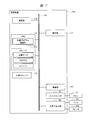
- FIG. 1 is an explanatory diagram illustrating an example of a configuration of the imaging apparatus 100 according to the first embodiment.
- the imaging device 100 is made of, for example, a smartphone or a tablet.
- the imaging apparatus 100 includes a communication interface 113, a control unit 114, a display unit 117, an input unit 115, a signal separation unit 121, a tuner / demodulation unit 122, a storage 125, a mobile communication interface 131, a memory 132, an acceleration sensor unit 133, It has a geomagnetic sensor unit 134, a GPS receiving unit 135, a gyro sensor unit 136, an imaging unit 140, a switch input unit 150, and a voice input / output unit 160, and the respective processing units are connected via the bus 101. .
- the storage 125 which is a recording unit stores application programs.
- the control unit 114 serving as an image control unit can implement various functions by developing an application program from the storage 125 to the memory 132 and executing the application program.
- control unit 114 executing each application program will be described as being realized mainly by various program function units.
- the application program may be stored in the storage 125 in advance before the imaging apparatus 100 is shipped.
- it may be stored in a medium such as an optical medium such as a CD (Compact Disk) or DVD (Digital Versatile Disk) or a semiconductor memory and installed in the imaging apparatus 100 via a medium connection unit (not shown).
- a medium connection unit not shown.
- the communication interface 113 may be downloaded and installed from an external network (not shown) via the communication interface 113 and a wireless router (not shown). Or you may download and install from a delivery source via the base station which is not shown in figure via the mobile communication interface 131.
- the application program can be realized by hardware as a processing unit having the same function.
- each processing unit plays a main role in realizing each function.
- the communication interface 113 is connected to a wireless router (not shown) via a wireless LAN or the like.
- the communication interface 113 is connected to an external network via a wireless router, and transmits / receives information to / from a server on the external network.
- the communication interface 113 may be mounted with chips that perform different communication methods. Further, it may be mounted as a single chip that handles a plurality of communication methods.
- the mobile communication interface 131 is connected to a communication network through a base station using a mobile communication network such as a third generation mobile communication system (hereinafter referred to as “3G”) or LTE (Long Term Evolution) system, Information can be exchanged with a server on the communication network.
- a mobile communication network such as a third generation mobile communication system (hereinafter referred to as “3G”) or LTE (Long Term Evolution) system.
- 3G third generation mobile communication system
- LTE Long Term Evolution
- 3G includes GSM (registered trademark) (Global System for Mobile Communications) system, W-CDMA (Wideband Code Division Multiple Access) system, CDMA2000 system, UMTS (Universal Mobile Telecommunications System) system, and the like.
- GSM Global System for Mobile Communications
- W-CDMA Wideband Code Division Multiple Access
- CDMA2000 Code Division Multiple Access 2000
- UMTS Universal Mobile Telecommunications System
- connection with the external network by the communication interface 113 can be prioritized over the communication network connection by the mobile communication interface 131.
- the control unit 114 receives a user operation request via the switch input unit 150, and controls the signal separation unit 121, the display unit 117, the communication interface 113, and various program function units.
- control unit 114 can acquire various types of information from an external network via the communication interface 113 and the wireless router, or from a server on the external network via the mobile communication interface 131 and the base station. It also has a function to pass to
- the storage 125 is controlled by an instruction from the control unit 114 and can store an application program. Various information created by the application program is stored.
- content such as a video / audio stream may be stored from a signal received from the tuner / demodulator 122, the communication interface 113, or the mobile communication interface 131.
- the storage 125 may be built in the imaging apparatus 100 or may be a portable memory that can be attached to and detached from the imaging apparatus 100.
- the memory 132 is controlled by an instruction from the control unit 114.
- the function unit of the application program stored in the storage 125 is expanded in the memory 132 by the control unit 114.
- the display unit 117 displays images and videos stored in the storage 125, broadcast / distributed videos, UI for various operations, and the like.
- the image and video may be an image generated by an application program, or may be an image or video of content received via the tuner / demodulator 122.
- it may be an image or video received from a server on an external network via the communication interface 113, or an image or video received from a television receiver (not shown) via the communication interface 113.
- an image or video distributed from a server on the communication network via the mobile communication interface 131 may be used.
- the display unit 117 may be configured integrally with, for example, a touch panel described later.
- the input unit 115 receives an operation on the imaging apparatus 100 from the user and inputs control information related to the input operation.
- a touch panel or the like can be used.
- various operations may be configured using physical buttons.
- any object on the touch panel such as an icon
- any object on the touch panel can be freely moved by performing a drag operation or a flick operation.
- a tap operation or a double tap operation an object or the like can be activated or switched to another screen.
- the drag operation is an operation that moves while touching an object with a finger.
- the flick operation is an operation of moving an object or the like on the screen by flicking a finger.
- the tap operation is an operation of hitting an object etc. once with a finger, and the double tap operation is an operation of hitting an object etc. twice.
- each operation of the touch panel described above is referred to as a drag operation, a flick operation, and a tap operation.
- the tuner / demodulator 122 and the signal separator 121 function as a television receiver.
- the tuner / demodulator 122 tunes to a desired television channel.
- the signal separation unit 121 separates video data, audio data, caption text data, program information, and the like for each type of the transport stream obtained by the tuner / demodulation unit 122 and the content stream obtained via the communication interface 113. .
- the acceleration sensor unit 133 serving as a position detection unit measures the acceleration applied to the imaging apparatus 100.
- the control unit 114 can know which part of the imaging device 100 is above by measuring the gravitational acceleration by the acceleration sensor unit 133, for example. As a result, the upper part of the screen displayed on the display unit 117 is displayed so as to match the upper part measured by the acceleration sensor unit 133. As a result, it is possible to display a screen that matches the way the user holds the imaging device 100.
- the geomagnetic sensor unit 134 measures geomagnetism by using a plurality of magnetic sensors.
- the GPS receiver 135 receives signals transmitted from a plurality of satellites using GPS (Global Positioning System).
- the control unit 114 can calculate the position information of the imaging device 100 based on the signal received by the GPS receiving unit 135.
- the gyro sensor unit 136 measures the angular velocity of the imaging device 100 that occurs when the user moves the imaging device 100.
- the imaging unit 140 includes an optical system such as a lens, an image sensor, and a signal processing circuit.
- the control unit 114 controls the exposure control, the focus control, the acquired image pixel number control, the compression control of the image capturing unit 140, and the recording control of the image captured by the image capturing unit 140 in the storage 125. Control according to the control program.
- the audio input / output unit 160 inputs / outputs an audio input signal from a microphone mounted on the imaging apparatus 100 and an audio output signal to the speaker 162, and the control unit 114 controls the volume of the audio input / output. Is done.
- the switch input unit 150 captures switch information in accordance with the operation of a physical button 151 (one or more), captures the switch information through the bus 101, and uses it to control various application programs as necessary. Is done.
- buttons 151 it is used to adjust the volume of audio output, that is, to control volume up / down according to the two buttons 151.
- One button 151 or a plurality of buttons 151 may be provided.
- the imaging apparatus 100 can take a high-resolution photograph with a large number of pixels or a low-resolution photograph with a small number of pixels by a shutter input method described later at the time of photographing. Accordingly, for example, when the user of the imaging apparatus 100 takes a picture that the SNS wants to upload, a low-resolution picture is taken, and when a user wants to leave a beautiful scenery such as a landscape, a high-resolution picture is taken by a single shutter operation. Can be recorded.
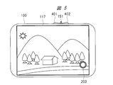
- FIG. 2 is an explanatory diagram showing an example of shutter input when the imaging apparatus 100 in FIG. 1 is controlled by a camera shooting program.
- FIG. 2 shows a display screen state at the time of camera photographing, and is a state in which an image to be photographed is displayed on the display unit 117 of the imaging apparatus 100.
- the display unit 117 includes a monitor image captured by the imaging unit 140 illustrated in FIG. 1, a high-resolution shutter button 201 for still images superimposed thereon, and a low-resolution shutter button 202. And a moving image shooting button 203 are respectively displayed.
- the shutter button 201 is a first button
- the shutter button 202 is a second button.
- the superimposing display control of these monitor images, the high-resolution shutter button 201, the low-resolution shutter button 202, and the moving image shooting button 203 is performed by the control unit 114 in FIG.
- control unit 114 When the low-resolution shutter button 202 in FIG. 2 is selected, the control unit 114 performs resolution setting processing and compression processing suitable for the low-resolution image on the imaging unit 140 by the touch detection function of the display unit 117. And recording control to the storage 125 is performed.
- control unit 114 When the high-resolution shutter button 201 is selected, the control unit 114 performs resolution setting processing and compression processing suitable for a high-resolution image on the imaging unit 140 by the touch detection function of the display unit 117, and stores Recording control to 125 is performed.
- the user can perform resolution and compression processing for the user's application and record only by pressing the shutter button once. As a result, it is possible to efficiently use the storage 125 having a limited capacity without performing complicated operations.
- the capacity in the storage 125 can be used effectively.
- buttons are arranged in the vertical direction on the right side of the screen of the display unit 117.
- the same effect as described above can be obtained even if the shutter button 201 and the shutter button 202 are arranged on the left and right sides of the display screen. .
- FIG. 3 is an explanatory diagram showing an example of a shutter input method when controlled by the camera photographing program according to the third embodiment.
- FIG. 3 also shows a display screen state at the time of photographing by the imaging apparatus 100 of FIG. 1 of the first embodiment, and a state in which an image to be photographed is displayed on the display unit 117 of the imaging apparatus 100. It is.
- the difference from FIG. 2 of the first embodiment is that the high-resolution shutter button 201 is displayed larger than the low-resolution shutter button 202.
- the user can easily identify the shutter buttons 201 and 202. As a result, erroneous selection of the shutter button can be reduced.
- the present invention is not limited to this.
- the same effect can be obtained by a technique such as changing the shape of the shutter button or changing the color.
- the display position of the shutter button may be set according to the user's preference such as the left side, upper part, and lower part of the screen.
- the user is left-handed, there is an advantage that it is easy to operate if it is displayed on the left side, and it is set according to the subject by setting at the upper or lower side of the screen, and the angle of view of the subject is set It is possible to obtain the effect of facilitating.
- FIG. 4 is an explanatory diagram illustrating an example of switching between high resolution and low resolution of an image according to a shooting situation according to the third embodiment.
- FIG. 4A shows a situation when a distant scene is photographed by the imaging apparatus 100 of FIG.
- FIG. 4B shows a situation when a dish placed on the table is photographed by the imaging apparatus 100 of FIG.
- the imaging apparatus 100 in FIG. 1 is used in a standing state.
- the case shown in FIG. 4B is an application for uploading to the SNS, and a low-resolution photograph is often sufficient.
- the imaging apparatus 100 of FIG. 1 is used in a laid state. That is, the imaging apparatus 100 is used so as to have a depression angle.
- the resolution is set to be different depending on the orientation of the imaging apparatus 100. That is, the case of FIG. 4A is taken at a high resolution, and the case of FIG. 4B is taken at a low resolution. In this way, the resolution and compression rate of the photograph are switched according to the orientation of the imaging device 100. As a result, the user can switch the resolution and compression rate of the photo in accordance with the orientation of the imaging apparatus 100 simply by pressing the shutter button.
- the inclination of the imaging device 100 is detected by the acceleration sensor unit 133 in FIG.
- the control unit 114 determines that the imaging device 100 has been laid down when the depression angle detected by the acceleration sensor unit 133 is equal to or greater than a preset angle. Based on the determination result, the control unit 114 controls the resolution and compression rate of the imaging unit 140 and controls recording of the obtained image in the storage 125 of FIG.
- the storage 125 of the limited storage 125 can be used without performing a more complicated operation and without the user being aware of it.
- the capacity can be used efficiently.
- FIG. 5 is an explanatory diagram illustrating an example of a shooting situation in the imaging apparatus 100 according to the fourth embodiment.
- FIG. 5 shows a display screen state at the time of shooting by the imaging apparatus 100.
- the configuration of the imaging apparatus 100 is the same as that in FIG.
- the imaging apparatus 100 is provided with a button 151.
- the button 151 is a seesaw type, and has a shape that allows two inputs, a button input unit 401 and a button input unit 402.
- the seesaw type button is often used for up and down operations such as voice output.
- the button input unit 401 of the button 151 is assigned to a high resolution and the button input unit 402 is assigned to a low resolution shutter operation. Is.
- buttons for low-resolution and high-resolution shooting sorting operations as well as to increase the portion of the screen where the subject is captured.
- the moving image shooting button 203 is displayed on the display unit of FIG. 1, but when the moving image shooting button 203 is also equipped with other buttons, the other buttons have their functions. May be assigned.
- shutter button display on the screen described with reference to FIGS. 2 and 3 is not limited.
- FIG. 6 is an explanatory diagram showing an example of a shooting situation in the imaging apparatus 100 according to the fifth embodiment.
- FIG. 6 shows a display screen state at the time of shooting by the image pickup apparatus 100.
- the configuration of the imaging apparatus 100 is the same as that in FIG.
- the moving image shooting button 203 is displayed at the same position as in FIG. A shutter button 501 for still image shooting is displayed above the moving image shooting button 203.
- the shutter button 501 for taking a still image takes a high-resolution photo when a light touch is performed once, and takes a low-resolution photo when a touch is made twice or more.
- the shutter button 501 may have a low resolution with a single touch and a high resolution with multiple touches. Or you may make it switch the resolution recorded by a short touch once and long press more than predetermined time.
- the high resolution and low resolution of the image recorded by the imaging apparatus 100 can be switched by a touch operation on one shutter button 501, the capacity of the limited storage 125 in FIG. 1 can be reduced with fewer operations. It can be used efficiently.
- the imaging apparatus 100 includes the GPS receiving unit 135 illustrated in FIG. By using the information from the GPS receiver 135, it can be grasped that the imaging device 100 is being used at a position far from home.
- location information about the home is stored in the storage 125 of FIG. 1 in the initial setting state.
- the control unit 114 determines that the imaging location is used based on information from the GPS reception unit 135, thereby grasping that the imaging device 100 is being used at a far position away from the vicinity of the home. Can do.
- the imaging apparatus in the first to sixth embodiments has a wireless terminal configuration mainly referred to as a smart phone.
- a configuration of an imaging apparatus mainly referred to as a digital camera will be described.
- FIG. 7 is an explanatory diagram showing an example of the configuration of the imaging apparatus 100 according to the seventh embodiment.
- the gyro sensor unit 136 and the voice input / output unit 160 are not provided in the imaging apparatus 100 of FIG.
- Other configurations are the same as those of the imaging apparatus 100 in FIG.
- the external storage 170 is a portable storage that can be detached from the imaging apparatus 100, such as an SD card.
- control program of the imaging apparatus 100 main body is stored in the storage 125, and the control unit 114 expands the control program from the storage 125 to the memory 132, and the control unit 114 executes various functions. Can be realized.
- control unit 114 executing each application program will be described as being realized mainly by various program function units.
- FIG. 8 is an explanatory diagram showing an example of shutter input by the imaging apparatus 100 of FIG.
- FIG. 8 shows a display screen state at the time of camera photographing, and is a state in which an image to be photographed is displayed on the display unit 117 of the imaging apparatus 100.
- control is performed such that a plurality of control buttons are displayed on the screen, and the shooting is performed by changing the resolution at the time of shooting, but in FIG. A plurality of buttons are used to form a shutter button to switch between high-resolution and low-resolution shooting.
- two shutter buttons 701 and 702 are provided on the upper right of the main body of the imaging apparatus 100, respectively. These shutter buttons 701 and 702 are assigned low-resolution and high-resolution shooting functions.
- the user can perform high-resolution and low-resolution shooting and recording with a single button operation.
- the limited capacity of the external storage 170 in FIG. 7 can be used efficiently.
- FIG. 9 is an explanatory diagram showing another example of the shutter button in FIG.
- each has a shutter button 801 and a resolution switching button 802, and these shutter button 801 and resolution switching button 802 are arranged at positions different from the shutter buttons 701 and 702 in FIG.
- the shutter button 801 is provided on the upper right part of the front surface of the imaging apparatus 100 main body, and the resolution switching button 802 is provided on the right side of the display part 117 provided on the rear surface of the imaging apparatus 100 main body.
- the shutter button 801 when the shutter button 801 is pressed without pressing the resolution switching button 802, the image is recorded and recorded at a high resolution. Further, when the shutter button 801 is pressed while pressing the resolution switching button 802, shooting and recording are performed at a low resolution.
- the user can easily perform high-resolution or low-resolution shooting and recording with a single button operation.
- the limited capacity of the external storage 170 can be used efficiently.
- FIG. 8 shows an example in which shooting and recording are performed with low resolution when the resolution switching button 802 is pressed, and high resolution when the resolution switching button 802 is not pressed. There is no limit, and vice versa. That is, shooting and recording are performed with high and low resolution when the resolution switching button 802 is pressed, and with low resolution when the button is not pressed.
- this invention is not limited to the above-mentioned Example, Various modifications are included.
- the above-described embodiments have been described in detail for easy understanding of the present invention, and are not necessarily limited to those having all the configurations described.
- a part of the configuration of one embodiment can be replaced with the configuration of another embodiment, and the configuration of another embodiment can be added to the configuration of one embodiment.
- each of the above-described configurations may be configured so that a part or all of them are configured by hardware or realized by executing a program by a processor.
- control lines and information lines indicate what is considered necessary for the explanation, and not all the control lines and information lines on the product are necessarily shown. Actually, it may be considered that almost all the components are connected to each other.
- DESCRIPTION OF SYMBOLS 100 Imaging device 101 Bus
Abstract
撮像装置100は、撮像部140、表示部117、ストレージ125、制御部114、シャッタボタン201,202を有する。撮像部140は、光学像から画像データを取得する。表示部117は、画像データを表示する。ストレージ125は、撮像部140が撮像した画像を記録する。制御部114は、撮像部140が撮影する画像データの画素数を選択する。シャッタボタン201,202は、撮像部160に光学像を撮影する撮像実行指示を出力する。また、制御部114は、シャッタボタン201が選択された際に撮像部140が取得する画像データの画素数が高解像度の画素数となるように撮像部140を制御し、シャッタボタン202が選択された際に撮像部140が取得する画像データの画素数が低解像度の画素数となるように撮像部140を制御する。
Description
本発明は、撮像装置に関し、特に、写真撮影の際における画像データの記録に有効な技術に関する。
近年、デジタルカメラなどが広く普及している。デジタルカメラのような撮像装置の主な用途としては、例えば高画素数の写真撮影およびあまり多くの画素数が必要ではない低画素数の写真撮影などがある。
高画素数の写真撮影は、例えば撮影した画像を大きな写真に印刷して楽しむためなど行われ、低高画素数の写真撮影は、インターネット上のSNS(ソーシャル・ネットワーキング・サービス)などにアップロードするためなどに行われる。
上記した用途において撮影された画像データを限られた容量の記録媒体に記録する際に、該記録媒体を有効に利用することのできる技術として、必要な画質を維持しながら、最適な記録様式にて画像データを記録媒体に記録するものがある(例えば特許文献1参照)。
しかしながら 上記した特許文献1の技術では、シャッタボタンを操作した後に、解像度および圧縮率などをメニューで選んだ後に画像データの記録が行われる。そのため、シャッタボタンを押してから画像を記録するまでの操作が煩雑であるという問題がある。
本発明の目的は、煩雑な操作を行うことなく、用途に応じた画像を記録することのできる技術を提供することにある。
本発明の前記ならびにその他の目的と新規な特徴については、本明細書の記述および添付図面から明らかになるであろう。
本願において開示される発明のうち、代表的なものの概要を簡単に説明すれば、次のとおりである。
すなわち、代表的な撮像装置は、撮像部、表示部、記録部、画像制御部、第1のボタン、および第2のボタンを有する。撮像部は、光学像から画像データを取得する。表示部は、画像データを表示する。
記録部は、撮像部が撮像した画像を記録する。画像制御部は、撮像部が撮影する画像データの画素数を選択する。第1のボタンは、撮像部に光学像を撮影する撮像実行指示を出力する。第2のボタンは、撮像部に光学像を撮影する撮像実行指示を出力する。
画像制御部は、第1のボタンが選択された際に撮像部が取得する画像データの画素数が第1の画素数となるように撮像部を制御し、第2のボタンが選択された際に撮像部が取得する画像データの画素数が第1の画素数よりも低い画素数である第2の画素数となるように撮像部を制御する。
特に、第1のボタンおよび第2のボタンは、表示部に表示されるソフトウェアボタンである。また、表示部に表示される第1のボタンおよび第2のボタンは、大きさが異なる。
本願において開示される発明のうち、代表的なものによって得られる効果を簡単に説明すれば以下のとおりである。
撮影時に煩雑な操作を行うことなく、用途に応じた解像度にて記録を行うことができる。
以下の実施の形態においては便宜上その必要があるときは、複数のセクションまたは実施の形態に分割して説明するが、特に明示した場合を除き、それらはお互いに無関係なものではなく、一方は他方の一部または全部の変形例、詳細、補足説明等の関係にある。
また、以下の実施の形態において、要素の数等(個数、数値、量、範囲等を含む)に言及する場合、特に明示した場合および原理的に明らかに特定の数に限定される場合等を除き、その特定の数に限定されるものではなく、特定の数以上でも以下でもよい。
さらに、以下の実施の形態において、その構成要素(要素ステップ等も含む)は、特に明示した場合および原理的に明らかに必須であると考えられる場合等を除き、必ずしも必須のものではないことは言うまでもない。
同様に、以下の実施の形態において、構成要素等の形状、位置関係等に言及するときは特に明示した場合および原理的に明らかにそうではないと考えられる場合等を除き、実質的にその形状等に近似または類似するもの等を含むものとする。このことは、上記数値および範囲についても同様である。
また、実施の形態を説明するための全図において、同一の部材には原則として同一の符号を付し、その繰り返しの説明は省略する。
以下、実施の形態を詳細に説明する。
(実施の形態1)
〈撮像装置の構成例〉
図1は、本実施の形態1による撮像装置100における構成の一例を示す説明図である。
〈撮像装置の構成例〉
図1は、本実施の形態1による撮像装置100における構成の一例を示す説明図である。
撮像装置100は、例えばスマートフォンやタブレットなどからなる。この撮像装置100は、通信インタフェース113、制御部114、表示部117、入力部115、信号分離部121、チューナ/復調部122、ストレージ125、移動体通信インタフェース131、メモリ132、加速度センサ部133、地磁気センサ部134、GPS受信部135、ジャイロセンサ部136、撮像部140、スイッチ入力部150、および音声入出力部160を有しており、それぞれの処理部がバス101を介して接続されている。
また、記録部であるストレージ125は、アプリケーションプログラムを格納する。画像制御部となる制御部114は、ストレージ125からアプリケーションプログラムをメモリ132に展開して、該アプリケーションプログラムを実行することにより、各種機能を実現することができる。
以後の説明では説明を簡単にするため、制御部114が各アプリケーションプログラムを実行して実現する各種機能を、各種プログラム機能部が主体となって実現することとして説明する。
なお、アプリケーションプログラムは、撮像装置100が出荷されるまでに予めストレージ125に格納されていてもよい。あるいはCD(Compact Disk)やDVD(Digital Versatile Disk)などの光学メディアや半導体メモリなどの媒体に格納されて図示しない媒体接続部を介して撮像装置100にインストールされてもよい。
また、通信インタフェース113および図示しない無線ルータを介して図示しない外部ネットワークからダウンロードしてインストールしてもよい。もしくは移動体通信インタフェース131を介して図示しない基地局を介して配信元からダウンロードしてインストールしてもよい。
さらに、ネットワークを介してアプリケーションプログラムを取得したパーソナルコンピュータに図示しない外部機器接続I/Fを介して接続し、該パーソナルコンピュータから撮像装置100にムーブまたはコピーしてインストールすることも可能である。
また、アプリケーションプログラムは、同様の機能を持つ処理部として、ハードウェアにて実現することも可能である。ハードウェアとして実現する場合は、各処理部が主体となって各機能を実現する。
通信インタフェース113は、無線LANなどにより、図示しない無線ルータに接続される。また、通信インタフェース113は、無線ルータを介して外部ネットワークと接続され、外部ネットワーク上のサーバーなどと情報の送受信を行う。
無線ルータとの通信機能に加えて、またはこれに替えて、Wi‐Fi(登録商標)などの無線LANなどの技術で、無線ルータを介さずにサーバと直接通信することが可能である。通信インタフェース113は、異なる通信方式を行うチップをそれぞれ実装してもよい。また、複数の通信方式を扱う1つのチップとして実装されていてもよい。
移動体通信インタフェース131は、第3世代移動通信システム(以下「3G」と表記する)、またはLTE(Long Term Evolution)方式などの移動体通信網を利用して基地局を通して通信ネットワークに接続され、通信ネットワーク上のサーバと情報の送受信を行うことができる。
3Gは、GSM(登録商標)(Global System for Mobile Communications)方式、W-CDMA(Wideband Code Division Multiple Access)方式、CDMA2000方式、あるいはUMTS(Universal Mobile Telecommunications System)方式などである。
また、通信インタフェース113による外部ネットワークとの接続を移動体通信インタフェース131による通信ネットワーク接続より優先するようにすることもできる。
制御部114は、ユーザの操作要求をスイッチ入力部150を経由して受け取り、信号分離部121、表示部117、通信インタフェース113、および各種プログラム機能部を制御する。
さらに、制御部114は、通信インタフェース113および無線ルータを経由して外部ネットワーク、または、移動体通信インタフェース131および基地局を経由して外部ネットワーク上のサーバから各種情報を取得でき、各種プログラム機能部に渡す機能も有する。
ストレージ125は、制御部114の指示により制御され、アプリケーションプログラムを保存することができる。また、アプリケーションプログラムにて作成した各種情報を保存する。
また、チューナ/復調部122、通信インタフェース113、または移動体通信インタフェース131から受信した信号から映像音声ストリームなどのコンテンツを保存してもよい。ストレージ125は、撮像装置100に内蔵されたものでもよいし、撮像装置100に着脱可能な可搬型のメモリであってもよい。
メモリ132は、制御部114の指示により制御される。制御部114によってメモリ132には、ストレージ125に格納しているアプリケーションプログラムの機能部が展開される。
表示部117は、ストレージ125に格納された画像や映像、放送・配信された映像、各種操作をするためのUIなどなどを表示する。画像、映像は、アプリケーションプログラムにて生成された画像でもよく、チューナ/復調部122を介して受信したコンテンツの画像、映像でもよい。
あるいは、通信インタフェース113を介して外部ネットワーク上のサーバから受信した画像、映像でもよく、通信インタフェース113を介して図示しないテレビ受信機から受信した画像、映像でもよい。
あるいは移動体通信インタフェース131を介して通信ネットワーク上のサーバから配信された画像、映像でもよい。また、表示部117は、例えば後述するタッチパネルなどと一体として構成されてもよい。
入力部115は、ユーザからの撮像装置100に対する操作を受け付け、入力操作に関する制御情報を入力するものであり、例えば、タッチパネルなどを用いることができる。以下、本実施の形態では、タッチパネルを使用した例について説明するが、各種操作は、物理的なボタンを用いる構成でもよい。
タッチパネルを使用することにより、タッチパネル上の任意のオブジェクト、例えばアイコンなどをドラッグ操作あるいはフリック操作を行うことにより自由に移動したりすることができる。また、タップ操作またはダブルタップ操作を行うことにより、オブジェクトなどを活性化したり別の画面に切り替えたりすることができる。
ドラッグ操作は、オブジェクトなどを指でタッチした状態で移動する操作である。フリック操作は、画面上でオブジェクトなどを指をはじくようにして動かす操作である。タップ操作は、オブジェクトなどを指で1回叩く操作であり、ダブルタップ操作は、オブジェクトなどを2回叩く操作である。ここでは、上述のタッチパネルの各操作をドラッグ操作、フリック操作、およびタップ操作と称して説明する。
チューナ/復調部122および信号分離部121は、テレビ受信機の働きを有する。チューナ/復調部122は、所望のテレビのチャンネルに同調する。信号分離部121は、チューナ/復調部122で得たトランスポートストリームや通信インタフェース113を介して得たコンテンツのストリームについて、映像データ、音声データ、字幕文データ、番組情報などを種類ごとに分離する。
位置検出部となる加速度センサ部133は、撮像装置100にかかる加速度を測定する。制御部114は、例えば加速度センサ部133により重力加速度を測定することによって、撮像装置100のどの部分が上方であるのかを知ることができる。これによって、表示部117に表示させる画面の上方を加速度センサ部133が測定した上方と合わせるように表示させる。その結果、ユーザによる撮像装置100の持ち方に合わせた画面を表示させることができる。
地磁気センサ部134は、複数の磁気センサを利用するなどして地磁気を測定する。GPS受信部135は、GPS(Global Positioning System)を利用して複数の衛星から送信される信号を受信する。
制御部114は、GPS受信部135が受信した信号に基づいて、撮像装置100の位置情報を計算することができる。ジャイロセンサ部136は、撮像装置100をユーザが動かした場合などに発生する撮像装置100の角速度を測定する。
撮像部140は、レンズなどの光学系、イメージセンサ、および信号処理回路などからなる。制御部114は、撮像部140の露光制御、フォーカス制御、取得画像画素数制御、圧縮制御、ならびに撮像部140で撮影された画像をストレージ125への記録制御を、ストレージ125に記録されているカメラ制御のプログラムに従って制御する。
音声入出力部160には、撮像装置100に装備されたマイクからの音声入力信号およびスピーカ162への音声出力信号を入出力するものであり、制御部114にてその音声入出力のボリュームの制御が行われる。
スイッチ入力部150は、物理的なボタン151(1個でも複数でもよい)の操作に応じてスイッチ情報を取り込み、バス101を通じて制御部114に取り込まれ、必要に応じて各種アプリケーションプログラムの制御に使用される。
たとえば一例として、ボタン151の2個のボタンに応じて音声出力の大きさ調整、すなわちボリュームのアップダウンの制御に使用される。なお、ボタン151は、1個でもよいし、複数個あってもよい。
撮像装置100は、写真撮影時において、後述するシャッタ入力方法によって、画素数の大きい高解像度の写真または画素数の小さい低解像度の写真を撮影することができる。従って、撮像装置100のユーザが、例えばSNSのアップロードしたい写真を撮影する場合には解像度の小さい写真を、また、風景など美しく残したい場合などには高解像度な写真を1回のシャッタ操作で撮影して記録することができる。
〈解像度の切り替え例〉
図2は、図1の撮像装置100がカメラ撮影のプログラムによって制御されている際のシャッタの入力の一例を示す説明図である。図2においては、カメラ撮影時の表示画面状態を示したものであり、撮像装置100の表示部117に撮影対象の画像が表示されている状態である。
図2は、図1の撮像装置100がカメラ撮影のプログラムによって制御されている際のシャッタの入力の一例を示す説明図である。図2においては、カメラ撮影時の表示画面状態を示したものであり、撮像装置100の表示部117に撮影対象の画像が表示されている状態である。
図2に示すように、表示部117には、図1に示す撮像部140によって撮像されているモニタ画像とそれに重畳して静止画用の高解像度のシャッタボタン201と、低解像度のシャッタボタン202と、動画撮影用ボタン203がそれぞれ表示されている。シャッタボタン201は、第1のボタンであり、シャッタボタン202は、第2のボタンとなる。
これらのモニタ画像、高解像度のシャッタボタン201、低解像度のシャッタボタン202、および動画撮影用ボタン203の重畳表示制御は、図1の制御部114にて行われる。
そして、図2の低解像度のシャッタボタン202が選択された場合、制御部114は、表示部117のタッチ検出機能により、低解像度の画像に適した解像度設定処理および圧縮処理を撮像部140に対して行い、ストレージ125へ記録制御を行う。
また、高解像度のシャッタボタン201が選択された場合、制御部114は、表示部117のタッチ検出機能により高解像度の画像に適した解像度設定処理および圧縮処理を撮像部140に対して行い、ストレージ125へ記録制御を行う。
以上のように、ユーザは1回のシャッタボタンを押下する操作を行うだけで、ユーザの用途向けの解像度および圧縮処理を行い記録することができる。これによって、煩雑な操作を行うことなく、限られた容量のストレージ125を効率よく使うことができる。
また、用途に応じて撮影する写真の解像度を変更することができるので、ストレージ125における容量を有効に活用することができる。
なお、本説明においては、高解像度および低解像度の2つのシャッタボタンを使用する例を示したが、シャッタボタンの数は2つに限るものではない。3つ以上のシャッタボタンを使用した場合は、本例よりさらに細かく解像度、圧縮率の選択を1回のシャッタボタン押下操作にて記録制御できる利点がある。
また、本例では、表示部117の画面右側に縦方向にボタンを配置したが、シャッタボタン201、シャッタボタン202を表示画面左右に配置するなどしても上記と同様の効果を得ることができる。
(実施の形態2)
〈概要〉
前記実施の形態1では、表示されているシャッタボタン201,202の大きさが同じであったが、本実施の形態2においては、シャッタボタン201,202の大きさが異なるように表示される例について説明する。
〈概要〉
前記実施の形態1では、表示されているシャッタボタン201,202の大きさが同じであったが、本実施の形態2においては、シャッタボタン201,202の大きさが異なるように表示される例について説明する。
〈シャッタボタンの表示例〉
図3は、本実施の形態3によるカメラ撮影のプログラムによって制御されている際のシャッタの入力方法の一例を示す説明図である。
図3は、本実施の形態3によるカメラ撮影のプログラムによって制御されている際のシャッタの入力方法の一例を示す説明図である。
この図3においても、前記実施の形態1の図1の撮像装置100による撮影時の表示画面状態を示したものであり、撮像装置100の表示部117に撮影対象の画像が表示されている状態である。
図3の場合、前記実施の形態1の図2と異なる点は、高解像度用のシャッタボタン201が低解像度のシャッタボタン202よりも大きく表示されているところである。このように、シャッタボタン201,202の大きさをそれぞれ変えることによって、ユーザがシャッタボタン201,202を識別しやすくすることができる。その結果、シャッタボタンの誤選択を低減することができる。
なお、本実施の形態2では、シャッタボタンの大きさを変えて表示する例を示したが、これに限るものではない。シャッタボタンの形状を変える、あるいは色を変えるなどの技術によっても同様の効果を得ることができる。
また、シャッタボタンの表示位置を画面左側や上部、下部など、ユーザの好みに応じて設定できるようにしてもよい。その場合、例えばユーザが左利きの場合には、左側に表示すれば操作しやすくなるという利点があるし、画面上部、もしくは下部側に設定することで被写体に応じて選択して被写体の画角設定をしやすくする、といった効果を得ることができる。
(実施の形態3)
〈概要〉
前記実施の形態1,2では、シャッタボタンによって高解像度および低解像度を切り換えていたが、本実施の形態3においては、シャッタボタンを用いずに高解像度および低解像度を切り換える技術について説明する。
〈概要〉
前記実施の形態1,2では、シャッタボタンによって高解像度および低解像度を切り換えていたが、本実施の形態3においては、シャッタボタンを用いずに高解像度および低解像度を切り換える技術について説明する。
〈解像度の切り替え例〉
図4は、本実施の形態3による撮影状況による画像の高解像度または低解像度を切り替えの一例を示す説明図である。
図4は、本実施の形態3による撮影状況による画像の高解像度または低解像度を切り替えの一例を示す説明図である。
図4(a)は、遠くの景色を図1の撮像装置100によって撮影する際の状況を示したものである。また、図4(b)は、テーブルにおかれた料理などを図1の撮像装置100によって撮影する際の状況を示したものである。
図4(a)に示すように、旅行に行った際などに風景を撮影する場合などでは、写真として印刷する用途も多いため、高解像度にて写真を残したい場合が多い。この場合、図1の撮像装置100は、立てた状態にて使用する。
一方、図4(b)に示す場合は、SNSにアップする用途であり、低解像度の写真で済むことが多い。この場合、図1の撮像装置100は、寝かせた状態にて使用する。すなわち、撮像装置100に俯角が付くように使用する。
従って、撮像装置100の向きに応じて解像度が異なるように設定される。すなわち、図4(a)の場合は高解像度で撮影され、図4(b)の場合は低解像度にて撮影される。このように、撮像装置100の向きに応じて写真の解像度および圧縮率を切り替える。これによって、ユーザは、シャッタボタンを押下するだけで、撮像装置100の向きに応じて写真の解像度および圧縮率を切り替えることができる。
撮像装置100の傾きは、図1の加速度センサ部133にて検知する。制御部114は、加速度センサ部133が検知した俯角の角度が予め設定されている角度以上になると、撮像装置100が寝かされたと判定する。その判定結果に基づいて、制御部114は、撮像部140の解像度および圧縮率を制御し、得られた画像を図1のストレージ125へ記録制御する。
以上により、撮像装置100の撮影時の傾きに応じて記録する画像の高解像度/低解像度を切り替えることができるので、より煩雑な操作を行うことなく、ユーザが意識せず限りのあるストレージ125の容量を効率よく使用することができる。
(実施の形態4)
〈概要〉
本実施の形態4においては、高解像度および低解像度の設定をボタンに割り当てる技術について説明する。
〈概要〉
本実施の形態4においては、高解像度および低解像度の設定をボタンに割り当てる技術について説明する。
〈解像度の切り替え例〉
図5は、本実施の形態4による撮像装置100における撮影状況の一例を示す説明図である。この図5は、撮像装置100による撮影時の表示画面状態を示したものである。なお、撮像装置100の構成については、図1と同様であるので説明は省略する。
図5は、本実施の形態4による撮像装置100における撮影状況の一例を示す説明図である。この図5は、撮像装置100による撮影時の表示画面状態を示したものである。なお、撮像装置100の構成については、図1と同様であるので説明は省略する。
図5において、撮像装置100には、ボタン151が設けられている。ボタン151は、シーソー型からなり、ボタン入力部401およびボタン入力部402の2つの入力ができる形状からなる。
シーソー型のボタンは、音声出力などのアップ、ダウンの操作に用いられることが多いが、ここでは、ボタン151のボタン入力部401を高解像度、ボタン入力部402を低解像度のシャッタ操作にそれぞれ割り当てるものである。
このようにすれば、物理的なボタンを低解像度、高解像度撮影の振り分け操作にも使用できるとともに、撮影する画面の被写体が写っている部分が増えるという利点がある。また、図5では、動画撮影用ボタン203が図1の表示部に表示されているが、該動画撮影用ボタン203も他のボタンなどが装備されている場合には、他のボタンにその機能を割り当てるようにしてもよい。
もちろん、図2および図3にて説明した画面上へのシャッタボタン表示を併用することを制限するものではない。
(実施の形態5)
〈概要〉
本実施の形態5では、シャッタボタンのタッチ回数によって高解像度および低解像度を切り換える技術について説明する。
〈概要〉
本実施の形態5では、シャッタボタンのタッチ回数によって高解像度および低解像度を切り換える技術について説明する。
〈解像度の切り替え例〉
図6は、本実施の形態5による撮像装置100における撮影状況の一例を示す説明図である。
図6は、本実施の形態5による撮像装置100における撮影状況の一例を示す説明図である。
図6は、撮像装置100による撮影時の表示画面状態を示したものである。なお、撮像装置100の構成については、図1と同様であるので説明は省略する。
図6に示す撮像装置100では、動画撮影用ボタン203が図2と同様の位置に表示されている。そして、動画撮影用ボタン203の上方には、静止画撮影用のシャッタボタン501が表示されている。
この静止画撮影用のシャッタボタン501は、1回の軽いタッチを行った際、高解像度の写真を撮影し、2回もしくはそれ以上のタッチを行った際には低解像度の写真を撮影する。
またはシャッタボタン501を1回のタッチで低解像度、複数回のタッチで高解像度としてもよい。あるいは1回短いタッチと、所定時間以上の長押しで記録する解像度を切り替えるようにしてもよい。
これにより、撮像装置100が記録する画像の高解像度および低解像度を1つのシャッタボタン501へのタッチ操作によって切り替えることができるので、より少ない操作にて、限りのある図1のストレージ125の容量を効率よく使用することができる。
(実施の形態6)
〈概要〉
本実施の形態6においては、写真撮影場所に応じて、高解像度および低解像度を切り替える技術について説明する。
〈概要〉
本実施の形態6においては、写真撮影場所に応じて、高解像度および低解像度を切り替える技術について説明する。
〈解像度の切り替え例〉
撮像装置100は、前記実施の形態1にて説明したように、図1に示すGPS受信部135を有している。このGPS受信部135からの情報を用いることにより、自宅から遠い位置にて撮像装置100が使用されていることを把握することができる。
撮像装置100は、前記実施の形態1にて説明したように、図1に示すGPS受信部135を有している。このGPS受信部135からの情報を用いることにより、自宅から遠い位置にて撮像装置100が使用されていることを把握することができる。
この場合、初期設定状態にて図1のストレージ125に自宅付近の位置情報を記憶させておく。制御部114は、撮像装置100を使用する際に、GPS受信部135からの情報に基づいて、撮影場所を判定することによって、自宅付近から離れた遠い位置において使用されていることを把握することができる。
その場合には、ユーザが旅行先である可能性が高いため、このような場合には高解像度にて記録を行う。また、自宅周辺にいる場合は、低解像度で撮影が行われるように切り替えるか、あるいは図2、図3、図4、図5などにて説明した制御を行うようにしてもよい。
それにより、旅行先などにおいて、きれいな高解像度による画像の撮り逃しを防ぐことができる。
(実施の形態7)
〈概要〉
前記実施の形態1~6における撮像装置は、主にスマートホンと呼ばれる無線端末の構成であったが、本実施の形態7では、主にデジタルカメラと呼ばれる撮像装置の構成について説明する。
〈概要〉
前記実施の形態1~6における撮像装置は、主にスマートホンと呼ばれる無線端末の構成であったが、本実施の形態7では、主にデジタルカメラと呼ばれる撮像装置の構成について説明する。
〈撮像装置の構成例〉
図7は、本実施の形態7による撮像装置100における構成の一例を示す説明図である。
図7は、本実施の形態7による撮像装置100における構成の一例を示す説明図である。
図7の撮像装置100が、図1の撮像装置100と異なる点は、外部ストレージ170が新たにもけられたところである。
さらに、図1の撮像装置100が有する通信インタフェース113、入力部115、信号分離部121、チューナ/復調部122、移動体通信インタフェース131、加速度センサ部133、地磁気センサ部134、GPS受信部135、ジャイロセンサ部136、および音声入出力部160が図7の撮像装置100には、設けられていない点である。その他の構成については、図1の撮像装置100と同様である。
外部ストレージ170は、撮像装置100から着脱可能な可搬型のストレージ、例えばSDカードなどである。
図7の撮像装置100では、撮像装置100本体の制御プログラムをストレージ125に格納しており、制御部114がストレージ125から制御プログラムをメモリ132に展開し、制御部114が実行することにより各種機能を実現することができる。
以後の説明では説明を簡単にするため、制御部114が各アプリケーションプログラムを実行して実現する各種機能を、各種プログラム機能部が主体となって実現することとして説明する。
〈解像度の切り替え例〉
図8は、図7の撮像装置100によるシャッタの入力の一例を示す説明図である。この図8においては、カメラ撮影時における表示画面状態を示したものであり、撮像装置100の表示部117に撮影対象の画像が表示されている状態である。
図8は、図7の撮像装置100によるシャッタの入力の一例を示す説明図である。この図8においては、カメラ撮影時における表示画面状態を示したものであり、撮像装置100の表示部117に撮影対象の画像が表示されている状態である。
図7の構成では、基本的に画面上に制御ボタンを複数表示し、それらによって撮影時の解像度を変えて撮影するといった制御を行ったが、図8では、撮像装置100本体に配置されるスイッチを複数使ってシャッタボタンを構成し、高解像度および低解像度の撮影を切り替える。
図8において、撮像装置100本体の右上には、2つのシャッタボタン701,702がそれぞれ設けられている。これらシャッタボタン701,702には、低解像度および高解像度の撮影機能を割り当てる。
こうすることによって、ユーザは1回のボタン操作で高解像度および低解像度の撮影、記録を行うことができる。限りのある図7の外部ストレージ170の容量を効率よく使用することができる。
〈シャッタボタンの他の例〉
また、図9は、図8のシャッタボタンの他の例について示した説明図である。
また、図9は、図8のシャッタボタンの他の例について示した説明図である。
図9では、シャッタボタン801および解像度切り替えボタン802をそれぞれ有し、これらシャッタボタン801および解像度切り替えボタン802は、図8のシャッタボタン701,702とは異なる位置に配置されている。
図9において、シャッタボタン801は、撮像装置100本体正面の右上部に設けられており、解像度切り替えボタン802は、撮像装置100本体背面に設けられた表示部117の右側に設けられている。
例えば解像度切り替えボタン802を押下せずにシャッタボタン801が押されると、高解像度で撮影、記録される。また、解像度切り替えボタン802を押下しながらシャッタボタン801を押下した場合には、低解像度での撮影、記録がなされる。
以上により、ユーザは1回のボタン操作にて高解像度または低解像度の撮影、記録を容易に行うことができる。また、限りのある外部ストレージ170の容量を効率よく使用することができる。
なお、図8では、解像度切り替えボタン802を押下すると低解像度、押下しない場合には高解像度による撮影、記録が行われる例を示したが、解像度切り替えボタン802を押下による撮影機能の割り付けは、特に制限はなく、その逆であってもよい。すなわち、解像度切り替えボタン802を押下すると高低解像度、押下しない場合には低解像度による撮影、記録が行われる。
以上、本発明者によってなされた発明を実施の形態に基づき具体的に説明したが、本発明は前記実施の形態に限定されるものではなく、その要旨を逸脱しない範囲で種々変更可能であることはいうまでもない。
なお、本発明は上記した実施例に限定されるものではなく、様々な変形例が含まれる。例えば、上記した実施例は本発明を分かりやすく説明するために詳細に説明したものであり、必ずしも説明した全ての構成を備えるものに限定されるものではない。また、ある実施例の構成の一部を他の実施例の構成に置き換えることが可能であり、また、ある実施例の構成に他の実施例の構成を加えることも可能である。また、各実施例の構成の一部について、他の構成の追加・削除・置換をすることが可能である。
また、上記の各構成は、それらの一部または全部が、ハードウェアで構成されても、プロセッサでプログラムが実行されることにより実現されるように構成されてもよい。また、制御線や情報線は説明上必要と考えられるものを示しており、製品上必ずしも全ての制御線や情報線を示しているとは限らない。実際には殆ど全ての構成が相互に接続されていると考えてもよい。
100 撮像装置
101 バス
113 通信インタフェース
114 制御部
115 入力部
117 表示部
121 信号分離部
122 チューナ/復調部
125 ストレージ
131 移動体通信インタフェース
132 メモリ
133 加速度センサ部
134 地磁気センサ部
135 GPS受信部
136 ジャイロセンサ部
140 撮像部
150 スイッチ入力部
151 ボタン
160 音声入出力部
162 スピーカ
170 外部ストレージ
201 シャッタボタン
202 シャッタボタン
203 動画撮影用ボタン
401 ボタン入力部
402 ボタン入力部
501シャッタボタン
701 シャッタボタン
801 シャッタボタン
802 解像度切り替えボタン
Claims (10)
- 光学像から画像データを取得する撮像部と、
前記画像データを表示する表示部と、
前記撮像部が撮像した画像を記録する記録部と、
前記撮像部が撮影する画像データの画素数を選択する画像制御部と、
前記撮像部に前記光学像を撮影する撮像実行指示を出力する第1のボタンと、
前記撮像部に前記光学像を撮影する撮像実行指示を出力する第2のボタンと、
を有し、
前記画像制御部は、前記第1のボタンが選択された際に前記撮像部が取得する前記画像データの画素数が第1の画素数となるように前記撮像部を制御し、前記第2のボタンが選択された際に前記撮像部が取得する前記画像データの画素数が前記第1の画素数よりも低い画素数である第2の画素数となるように前記撮像部を制御する、撮像装置。 - 請求項1記載の撮像装置において、
前記第1のボタンおよび前記第2のボタンは、前記表示部に表示されるソフトウェアボタンである、撮像装置。 - 請求項2記載の撮像装置において、
前記表示部に表示される前記第1のボタンおよび前記第2のボタンは、大きさが異なる、撮像装置。 - 請求項1記載の撮像装置において、
前記画像制御部は、前記記録部に前記画像データを記録する際に前記画像データのデータ圧縮を行う、撮像装置。 - 光学像から画像データを取得する撮像部と、
前記画像データを表示する表示部と、
前記撮像部が撮像した画像を記録する記録部と、
前記撮像部が撮影する画像データの画素数を選択する画像制御部と、
前記撮像部の傾きを検出する位置検出部と、
を有し、
前記画像制御部は、前記位置検出部が検出する前記撮像部の俯角が予め設定された角度よりも小さいと、前記撮像部が取得する前記画像データの画素数が第1の画素数となるように前記撮像部を制御し、前記位置検出部が検出する前記撮像部の俯角が予め設定された角度以上であると、前記撮像部が取得する前記画像データの画素数が前記第1の画素数よりも低い画素数である第2の画素数となるように前記撮像部を制御する、撮像装置。 - 請求項5記載の撮像装置において、
前記位置検出部は、加速度センサである、撮像装置。 - 請求項5記載の撮像装置において、
前記画像制御部は、前記記録部に前記画像データを記録する際に前記画像データのデータ圧縮を行う、撮像装置。 - 光学像から画像データを取得する撮像部と、
前記画像データを表示する表示部と、
前記撮像部が撮像した画像を記録する記録部と、
前記撮像部が撮影する画像データの画素数を選択する画像制御部と、
前記撮像部に前記光学像を撮影する撮像実行指示を出力する第3のボタンと、
前記撮像部が撮像する画像データの画素数を変更する画素数変更指示を出力する第4のボタンと、
を有し、
前記画像制御部は、前記第3のボタンによって撮像実行指示がされた際に前記撮像部が取得する前記画像データの画素数が第1の画素数となるように前記撮像部を制御し、前記第4のボタンによる画素数変更指示、および前記第3のボタンによる撮像実行指示がされた際に前記撮像部が取得する前記画像データの画素数が前記第1の画素数よりも低い画素数である第2の画素数となるように前記撮像部を制御する、撮像装置。 - 請求項8記載の撮像装置において、
前記画像制御部は、前記記録部に前記画像データを記録する際に前記画像データのデータ圧縮を行う、撮像装置。 - 請求項8記載の撮像装置において、
前記第3のボタンは、前記表示部に表示されるソフトウェアボタンであり、
前記画像制御部は、前記第3のボタンのタッチ回数によって前記撮像部が取得する前記画像データの画素数を前記第1の画素数または前記第2の画素数のいずれかに切り替える、撮像装置。
Priority Applications (1)
| Application Number | Priority Date | Filing Date | Title |
|---|---|---|---|
| PCT/JP2016/063275 WO2017187573A1 (ja) | 2016-04-27 | 2016-04-27 | 撮像装置 |
Applications Claiming Priority (1)
| Application Number | Priority Date | Filing Date | Title |
|---|---|---|---|
| PCT/JP2016/063275 WO2017187573A1 (ja) | 2016-04-27 | 2016-04-27 | 撮像装置 |
Publications (1)
| Publication Number | Publication Date |
|---|---|
| WO2017187573A1 true WO2017187573A1 (ja) | 2017-11-02 |
Family
ID=60160297
Family Applications (1)
| Application Number | Title | Priority Date | Filing Date |
|---|---|---|---|
| PCT/JP2016/063275 WO2017187573A1 (ja) | 2016-04-27 | 2016-04-27 | 撮像装置 |
Country Status (1)
| Country | Link |
|---|---|
| WO (1) | WO2017187573A1 (ja) |
Citations (7)
| Publication number | Priority date | Publication date | Assignee | Title |
|---|---|---|---|---|
| JPH0923375A (ja) * | 1995-07-10 | 1997-01-21 | Konica Corp | デジタルスチルカメラ、及びテレビ会議システム |
| JP2004064229A (ja) * | 2002-07-25 | 2004-02-26 | World Creative Lab:Kk | 電子メールへの画像自動付加方法 |
| WO2005022902A1 (ja) * | 2003-09-01 | 2005-03-10 | Matsushita Electric Industrial Co., Ltd. | 送信機能付きカメラと携帯電話機、画像データ取得送信プログラム |
| JP2008160703A (ja) * | 2006-12-26 | 2008-07-10 | Sky Kk | カメラ及びカメラ用プログラム |
| JP2011199503A (ja) * | 2010-03-18 | 2011-10-06 | Pfu Ltd | 撮像装置及びプログラム |
| JP2013048384A (ja) * | 2011-08-29 | 2013-03-07 | Olympus Imaging Corp | 撮像装置 |
| JP2013171199A (ja) * | 2012-02-21 | 2013-09-02 | Nikon Corp | 撮像装置 |
-
2016
- 2016-04-27 WO PCT/JP2016/063275 patent/WO2017187573A1/ja active Application Filing
Patent Citations (7)
| Publication number | Priority date | Publication date | Assignee | Title |
|---|---|---|---|---|
| JPH0923375A (ja) * | 1995-07-10 | 1997-01-21 | Konica Corp | デジタルスチルカメラ、及びテレビ会議システム |
| JP2004064229A (ja) * | 2002-07-25 | 2004-02-26 | World Creative Lab:Kk | 電子メールへの画像自動付加方法 |
| WO2005022902A1 (ja) * | 2003-09-01 | 2005-03-10 | Matsushita Electric Industrial Co., Ltd. | 送信機能付きカメラと携帯電話機、画像データ取得送信プログラム |
| JP2008160703A (ja) * | 2006-12-26 | 2008-07-10 | Sky Kk | カメラ及びカメラ用プログラム |
| JP2011199503A (ja) * | 2010-03-18 | 2011-10-06 | Pfu Ltd | 撮像装置及びプログラム |
| JP2013048384A (ja) * | 2011-08-29 | 2013-03-07 | Olympus Imaging Corp | 撮像装置 |
| JP2013171199A (ja) * | 2012-02-21 | 2013-09-02 | Nikon Corp | 撮像装置 |
Similar Documents
| Publication | Publication Date | Title |
|---|---|---|
| US8976270B2 (en) | Imaging device and imaging device control method capable of taking pictures rapidly with an intuitive operation | |
| US9389758B2 (en) | Portable electronic device and display control method | |
| JP4864295B2 (ja) | 画像表示システム、画像表示装置およびプログラム | |
| JP6328255B2 (ja) | マルチ撮像装置、マルチ撮像方法、プログラム、及び記録媒体 | |
| KR102090624B1 (ko) | 이미지 촬영장치 및 방법 | |
| US20130040700A1 (en) | Image capture device and image capture method | |
| US9742995B2 (en) | Receiver-controlled panoramic view video share | |
| KR20170023885A (ko) | 음성 또는 영상 통화 중 컨텍스트 정보 합성 및 전송 기법 | |
| JP6302564B2 (ja) | 動画編集装置、動画編集方法及び動画編集プログラム | |
| KR20170013877A (ko) | 동적 배향 잠금, 일정한 프레이밍 및 규정된 종횡비를 갖는 사진 비디오 카메라 | |
| JP2013232861A (ja) | 表示制御装置、表示制御方法、プログラムおよび記録媒体 | |
| CN110691187B (zh) | 电子装置、电子装置的控制方法和计算机可读介质 | |
| KR20140106265A (ko) | 이미지 촬영장치 및 방법 | |
| CN111385470B (zh) | 电子设备、电子设备的控制方法和计算机可读介质 | |
| CN110881097B (zh) | 显示控制设备、控制方法和计算机可读介质 | |
| KR102501713B1 (ko) | 영상 표시 방법 및 그 전자장치 | |
| CN111314600B (zh) | 电子装置、控制方法和计算机可读介质 | |
| JP6205068B2 (ja) | 撮像装置の操作装置、操作方法、及びプログラム | |
| WO2021255975A1 (ja) | 撮像装置、撮像制御装置、撮像装置の制御方法、プログラム | |
| WO2017187573A1 (ja) | 撮像装置 | |
| CA2804594A1 (en) | Methods and devices for capturing images | |
| US20220321827A1 (en) | Electronic device, control method of electronic device, and non-transitory computer readable storage medium | |
| CN110881102B (zh) | 摄像设备、摄像设备的控制方法和计算机可读介质 | |
| JP2010141736A (ja) | 撮像装置 | |
| JP2017228828A (ja) | 撮像装置、表示装置、及び撮像表示システム |
Legal Events
| Date | Code | Title | Description |
|---|---|---|---|
| NENP | Non-entry into the national phase |
Ref country code: DE |
|
| 121 | Ep: the epo has been informed by wipo that ep was designated in this application |
Ref document number: 16900445 Country of ref document: EP Kind code of ref document: A1 |
|
| 122 | Ep: pct application non-entry in european phase |
Ref document number: 16900445 Country of ref document: EP Kind code of ref document: A1 |
|
| NENP | Non-entry into the national phase |
Ref country code: JP |