WO2017187487A1 - 位置特定システム及び位置特定方法 - Google Patents
位置特定システム及び位置特定方法 Download PDFInfo
- Publication number
- WO2017187487A1 WO2017187487A1 PCT/JP2016/062946 JP2016062946W WO2017187487A1 WO 2017187487 A1 WO2017187487 A1 WO 2017187487A1 JP 2016062946 W JP2016062946 W JP 2016062946W WO 2017187487 A1 WO2017187487 A1 WO 2017187487A1
- Authority
- WO
- WIPO (PCT)
- Prior art keywords
- radio wave
- receiver
- transmitter
- radio
- time
- Prior art date
- Legal status (The legal status is an assumption and is not a legal conclusion. Google has not performed a legal analysis and makes no representation as to the accuracy of the status listed.)
- Ceased
Links
Images









Classifications
-
- G—PHYSICS
- G01—MEASURING; TESTING
- G01S—RADIO DIRECTION-FINDING; RADIO NAVIGATION; DETERMINING DISTANCE OR VELOCITY BY USE OF RADIO WAVES; LOCATING OR PRESENCE-DETECTING BY USE OF THE REFLECTION OR RERADIATION OF RADIO WAVES; ANALOGOUS ARRANGEMENTS USING OTHER WAVES
- G01S5/00—Position-fixing by co-ordinating two or more direction or position line determinations; Position-fixing by co-ordinating two or more distance determinations
- G01S5/02—Position-fixing by co-ordinating two or more direction or position line determinations; Position-fixing by co-ordinating two or more distance determinations using radio waves
-
- G—PHYSICS
- G01—MEASURING; TESTING
- G01S—RADIO DIRECTION-FINDING; RADIO NAVIGATION; DETERMINING DISTANCE OR VELOCITY BY USE OF RADIO WAVES; LOCATING OR PRESENCE-DETECTING BY USE OF THE REFLECTION OR RERADIATION OF RADIO WAVES; ANALOGOUS ARRANGEMENTS USING OTHER WAVES
- G01S2205/00—Position-fixing by co-ordinating two or more direction or position line determinations; Position-fixing by co-ordinating two or more distance determinations
- G01S2205/01—Position-fixing by co-ordinating two or more direction or position line determinations; Position-fixing by co-ordinating two or more distance determinations specially adapted for specific applications
- G01S2205/09—Position-fixing by co-ordinating two or more direction or position line determinations; Position-fixing by co-ordinating two or more distance determinations specially adapted for specific applications for tracking people
Definitions
- This case relates to a location identification system and location identification method.
- the worker is detected by the detection means provided at a predetermined position of the rail, and there is a possibility that the detailed position of the worker cannot be specified depending on the arrangement method.
- the detection means provided at a predetermined position of the rail, and there is a possibility that the detailed position of the worker cannot be specified depending on the arrangement method.
- the detection means provided at a predetermined position of the rail, and there is a possibility that the detailed position of the worker cannot be specified depending on the arrangement method.
- a large number of detection means must be provided.
- This case has been made in view of the above problems, and an object thereof is to provide a position specifying system and a position specifying method capable of specifying a detailed position of an operator.
- the positioning system includes a radio wave transmitter that transmits radio waves, and a radio wave that repeatedly moves along a predetermined route and receives the radio waves transmitted from the radio wave transmitter that exists within a radio wave reception range.
- a receiver an acquisition unit for acquiring a reception result of the radio wave at a certain time from the radio wave receiver, a specifying unit for specifying a position of the radio wave receiver at the certain time, and the radio wave receiver at the certain time
- An information processing device including a calculation unit that calculates a position of the radio wave transmitter based on the position and the reception result of the radio wave at the certain time.
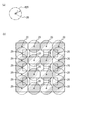
- FIG. 3A is a diagram illustrating a radio wave reception range of the receiver
- FIG. 3B is a diagram illustrating an arrangement example when the receiver is fixedly arranged. It is a figure which shows the example of arrangement
- FIG. 11A is a block diagram illustrating a hardware configuration of the information processing apparatus
- FIG. 11B is a functional block diagram of the information processing apparatus. It is a figure which shows an example of a transmitter detection table. It is a flowchart which shows an example of the worker position specific process which information processing apparatus performs.
- FIGS. 14 (a) to 14 (c) are diagrams (part 1) for explaining the identification of the worker's position
- FIG. 14 (d) shows the worker's position when a fixedly arranged receiver is used. It is a figure explaining specification of a position.
- FIG. 14 (a) to 14 (c) are diagrams (part 1) for explaining the identification of the worker's position
- FIG. 14 (d) shows the worker's position when a fixedly arranged receiver is used. It is a figure explaining specification of a position.
- FIG. 14 (a) to 14 (c) are diagrams (part 1) for explaining the identification of the worker's position
- FIG. 14 (d) shows the worker's position
- FIGS. 15A to FIG. 15C are diagrams (part 2) for explaining the identification of the position of the worker.
- FIGS. 16A to 16C are diagrams (part 3) for explaining the specification of the position of the operator. It is a figure which shows an example of an operator location information table. It is a figure explaining the other example of a receiver.
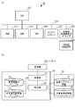
- FIG. 1 schematically shows a configuration of a position specifying system 100 according to an embodiment.
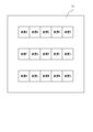
- the position specifying system 100 is a system for specifying the position at a certain point in time of an operator who works on the floor F1 of the factory where the devices A to O are arranged.
- the location system 100 includes a radio wave transmitter (hereinafter referred to as a transmitter) 30-1 to 30-m (m is an arbitrary integer), a radio wave receiver (hereinafter referred to as a receiver). 20-1 to 20-n (where n is an arbitrary integer), a database server 60, and an information processing apparatus 50.
- the receivers 20-1 to 20-n and the information processing apparatus 50 are connected via a wired or wireless network 80 such as the Internet, LAN (Local Area Network), WAN (Wide Area Network), or the like.
- the information processing apparatus 50 and the database server 60 are connected via a network such as a LAN.
- the transmitters 30-1 to 30-n are referred to as transmitters 30 and the receivers 20-1 to 20-n are referred to as receivers 20 unless otherwise distinguished.
- the transmitter 30 is, for example, a beacon device and transmits radio waves (beacon signals).
- the radio wave transmitted from the transmitter 30 includes transmitter ID information that is an identifier for uniquely identifying the transmitter 30.
- the transmitter 30 in order to specify the position of the worker by specifying the position of the transmitter 30, the transmitter 30 is attached to each worker who works in the floor F1 of FIG.
- the transmitter 30 is attached to the helmet worn by the operator so that the radio wave transmission surface is on the upper side, but may be attached to other positions. Further, the radio wave transmitting surface does not necessarily have to be directed upward as long as the receiver 20 can receive the radio wave from the transmitter 30.
- the receiver 20 is a beacon receiver, for example, and receives radio waves transmitted from the transmitter 30 existing in the radio wave reception range.
- the receiver 20 performs radio wave reception processing for receiving radio waves transmitted from the transmitter 30 at a predetermined time interval (for example, 2 ms). Each time the radio wave receiving process is performed, the receiver 20 transmits the time point when the radio wave receiving process is performed and the radio wave reception result to the information processing apparatus 50.
- the radio wave reception range R20 of the receiver 20 is a circle having a radius r centered on the receiver 20, as shown in FIG. Therefore, in order to specify the position of the operator (transmitter 30) in the floor F1 shown in FIG. 2, the receiver is arranged so that the radio wave reception range R20 covers an area where the transmitter 30 may exist. 20 need to be arranged.
- the receiver 20 is fixedly arranged, the receiver 20 is arranged as shown in FIG. 3B, for example, in order to cover an area where the transmitter 30 may exist. In this case, a total of 22 receivers 20 are arranged.
- the receiver 20 repeatedly moves along a predetermined route at a constant period. In other words, the receiver 20 repeats returning from the initial position to the original position (initial position) through a predetermined route. More specifically, the receiver 20 repeatedly moves along a predetermined route so that the movement locus of the radio wave reception range R20 covers an area where the transmitter 30 may exist. As a result, radio waves from the transmitter 30 can be received in an area where the transmitter 30 may exist, and the number of receivers 20 can be reduced.
- a plurality of receivers 20 are arranged and moved in the floor F1.
- the arrow represents the direction in which the receiver 20 moves.
- receivers 20-1 to 20-4 that reciprocate on lines L1 to L4, respectively, receivers 20-5 and 20-6 that are arranged on a concentric circle C1 and move on the circumference of the circle C1,
- a receiver 20-7 that moves on the circumference of a circle C2 different from the circle C1 is disposed.
- the receivers 20-5 and 20-6 move on the circumference of the circle C1
- the receiver 20-7 moves on the circumference of the circle C2
- the receiver 20 is arranged and repeatedly moved along a predetermined route, so that the transmitter 30 is transmitted by the seven receivers 20 in the area F ⁇ b> 1 for specifying the position of the worker. It is possible to receive radio waves from.
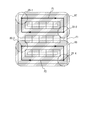
- the receiver 20 may be arranged and moved as shown in FIG. In FIG. 5, the receivers 20-1 and 20-2 that move so that the movement locus becomes the rectangle P1 and the receivers 20-3 and 20-4 that move so that the movement locus becomes the rectangle P2 are arranged. Has been. By moving the receivers 20-1 and 20-2 so that their movement trajectory is the rectangle P1, it becomes possible to receive radio waves from the transmitter 30 existing in the region R7. In addition, the receivers 20-3 and 20-4 move so that the movement trajectory is a rectangle P2, so that radio waves from the transmitter 30 existing in the region R8 can be received. As a result, in FIG.
- the radio waves from the transmitter 30 can be received by the four receivers 20 in the area F ⁇ b> 1 that is the target for specifying the position of the worker.
- the movement trajectory of the receiver 20 is not limited to a rectangle, and may be, for example, a polygon such as a triangle or a pentagon.
- the receiver 20 may be arranged and moved as shown in FIG. In FIG. 6, receivers 20-1 to 20-8 moving on different circles C3 to C10 are arranged.
- the receivers 20-1 to 20-8 move on the circles C3 to C10, respectively, it becomes possible to receive radio waves from the transmitters 30 existing in the regions R9 to R16.
- the radio waves from the transmitter 30 can be received by the eight receivers 20 in the area F ⁇ b> 1 that is the target for specifying the position of the worker.
- the receiver 20 is arranged so that the radio wave receiving surface is downward. Thereby, the radio wave from the transmitter 30 attached to the worker so that the radio wave transmission surface is upward can be received more reliably.
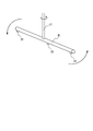
- the receiver 20 may move on a track installed above (for example, the ceiling) above the area where the operator works, or can fly in a three-dimensional manner, flying on a pre-programmed route. It may be moved by a drone device. Or you may move by being fixed to the member M1 attached to rotating shaft S1 as shown in FIG. In FIG. 7, when the member M1 rotates in the direction of the arrow by the rotation of the rotation shaft S1, the receiver 20 fixed to the member M1 repeatedly moves on the circumference.
- the moving method of the receiver 20 may be appropriately determined according to the layout of the place (factory or the like) where the position specifying system 100 is introduced and the constraint conditions.
- the moving speed a of the receiver 20 that moves on the line is set as follows.
- a ⁇ (S1-S2) / n- ⁇ r 2 ⁇ / 2xr
- S1 is the area of an area in which the radio wave from the transmitter 30 can be received when the receiver 20 moves (for example, in the case of the receiver 20-1 in FIG. 4, the area R1, FIG. 4).
- r is the radius of the radio wave reception range of the receiver 20
- n is the number of the receivers
- S2 is the area where the radio wave reception ranges of the receivers 20 overlap
- x is the transmission This represents a cycle for specifying the position of the machine 30.
- the position of the transmitter 30 can be specified with the desired period x using n receivers 20. That is, the radio wave from the transmitter 30 can be received by any one of the n receivers 20 for each period x.
- the database server 60 manages the device layout information 61 and the worker related information 63.
- the device layout information 61 will be described with reference to FIG.
- FIG. 8 shows an example of data of the device layout information 61.
- the device layout information 61 includes fields of “position”, “area classification”, and “device name”.
- the “position” field stores the coordinates (x, y) of each divided area when the entire area that is the target for specifying the position of the worker is divided as shown in FIG. 9, for example.
- the “area classification” field information indicating the classification of the area specified by the coordinates described above is stored.
- One of “blank areas” indicating that it does not correspond to any of the “areas” is stored.
- the “device name” field when “area classification” is “device area”, the names of devices arranged in the area are stored. For example, as shown in FIG. 9, it is assumed that the devices A to O are arranged, and an area indicated by hatching is defined as a work area. In this case, as shown in FIG. 8, the area classification of the position (1, 1) is “working area”, the area classification of the position “3, 1” is “blank area”, and the area of the position (3, 3). The classification is “device area” and the device name is “A”.
- the worker related information 63 is a table that associates the worker with the transmitter 30.
- the worker related information 63 includes fields of “worker ID” and “transmitter ID”.
- the “worker ID” field stores an identifier (for example, an employee number) for uniquely identifying the worker.
- the “transmitter ID” field stores an identifier for uniquely identifying the transmitter 30 attached to the worker identified by the worker ID. Therefore, by referring to the worker-related information 63, it is possible to specify the worker who has attached the transmitter 30 identified by the transmitter ID from the “transmitter ID”.
- the information processing apparatus 50 acquires the reception result of the radio wave transmitted by the transmitter 30 from the receiver 20 and specifies the position of each transmitter 30.
- the information processing apparatus 50 has a hardware configuration as shown in FIG. Specifically, as illustrated in FIG. 11A, the information processing apparatus 50 includes a CPU (Central Processing Unit) 511, a ROM (Read Only Memory) 512, a RAM (Random Access Memory) 513, and a storage device (HDD: HDD). Hard Disk Drive) 514, a network interface 515, a portable storage medium drive 517 that can read data stored in the portable storage medium 516, and the like. Each component of the information processing apparatus 50 is connected to the bus 518.
- a CPU Central Processing Unit
- ROM Read Only Memory
- RAM Random Access Memory
- HDD Hard Disk Drive
- the CPU 511 executes a program stored in the ROM 512 or the HDD 514 (including the worker position specifying program) or a program read by the portable storage medium drive 517 from the portable storage medium 516, whereby the information processing apparatus 50. Is made to function as each part of FIG.11 (b).
- the information processing apparatus 50 functions as an acquisition unit, an acquisition unit 51 as a specific unit, and a calculation unit 53 when the CPU 511 executes a program.
- the acquisition unit 51 acquires (receives) the time when the receiver 20 executes the radio wave reception process and the reception result of the radio wave from the receiver 20. In addition, when the receiver 20 has received a radio wave from the transmitter 30, the acquisition unit 51 acquires information on the transmitter ID included in the received radio wave.
- the acquisition unit 51 specifies the position of the receiver 20 at the time when the receiver 20 executes the radio wave reception process.
- the position of the receiver 20 when the radio wave reception process is performed is that the receiver 20 repeatedly moves along a predetermined route, so that the initial position of the receiver 20 and the time elapsed since the receiver 20 started moving. It can be calculated based on time.
- a sensor for detecting the receiver 20 may be provided on a line on which the receiver 20 moves, and the position of the receiver 20 may be specified based on the output value of the sensor.
- a GPS (Global Positioning System) sensor or the like may be attached to the receiver 20, and the position of the receiver 20 may be specified based on the output value of the GPS sensor.
- the acquisition unit 51 records the information acquired from the receiver 20 and the specified position of the receiver 20 in the transmitter detection table 55.
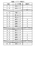
- FIG. 12 shows an example of the transmitter detection table 55.
- the transmitter detection table 55 includes fields of “date”, “time”, “receiver ID”, “receiver position”, and “transmitter ID”.
- the “date” field the date when the receiver 20 performs the radio wave reception process is stored.
- the “time” field information indicating the time when the receiver 20 performs the radio wave reception process is stored.
- the number of time steps after the receiver 20 starts moving is stored in the “time” field. The number of time steps indicates the time when the time obtained by multiplying the number of time steps by the time interval at which the receiver 20 performs radio wave reception processing has elapsed since the start of movement of the receiver 20.
- the “receiver ID” field an identifier for uniquely identifying the receiver 20 is stored.
- the “receiver position” field stores the position of the receiver 20 specified by the acquisition unit 51 when the receiver 20 performs the radio wave reception process.
- transmitter ID when the receiver 20 receives a radio wave, information of a transmitter ID for uniquely identifying the transmitter 30 that has transmitted the radio wave is stored. If it is not received, no data is registered.
- the calculation unit 53 calculates the position of each worker at a certain point in time based on the data registered in the transmitter detection table 55. Specifically, the calculation unit 53 calculates the position of each worker by performing the worker position specifying process shown in FIG.
- FIG. 13 is a flowchart illustrating an example of the worker position specifying process performed by the calculation unit 53. The process of FIG. 13 is executed when, for example, the information processing apparatus 50 requests execution of the worker position specifying process.
- step S11 the calculation unit 53 extracts data at different time points t and t + ⁇ t of the same receiver at which the radio wave reception ranges overlap from the data registered in the transmitter detection table 55. . ⁇ t is set within a range where radio wave reception ranges at time t and time t + ⁇ t overlap.
- step S13 the calculation unit 53 determines whether or not the receiver 20 is receiving radio waves at time t. If the receiver 20 is receiving radio waves at time t, the determination in step S13 is affirmed, and the calculation unit 53 proceeds to step S15.
- step S15 the calculation unit 53 determines whether or not the radio wave is received from the same transmitter 30 as the transmitter 30 that has transmitted the radio wave received by the receiver 20 at the time t at the time t + ⁇ t. When determination here is denied, the calculation part 17 transfers to step S17.
- the calculation unit 53 identifies the radio wave reception range at time t that does not overlap with the radio wave reception range at time t + ⁇ t.
- step S ⁇ b> 19 based on the device layout information 61, the calculation unit 53 specifies an area excluding the device area from the range specified in step S ⁇ b> 17 as the position of the transmitter 30 at time t.
- the reason why the device area is excluded is that the transmitter 30 cannot exist in the device area.
- the transmitter 30 is located at the position (1, 7) at the time t and the time t + ⁇ t, and the receiver 20 is present at the positions shown in FIGS. 14 (a) and 14 (b).
- the receiver 20 receives the radio wave of the transmitter 30 (step S13 / YES).
- the transmitter 30 does not exist within the radio wave reception range R20, and therefore the receiver 20 does not receive the radio waves from the transmitter 30 (step S15 / NO).
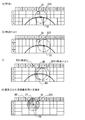
- the calculation unit 53 identifies the radio wave reception range at time t (region RA + RB in FIG. 14 (c)) that does not overlap with the radio wave reception range at time t + ⁇ t (step S17). Then, the calculation unit 53 identifies an area RB excluding the device area (area RA) from the identified range (area RA + RB) as the position where the transmitter 30 exists at time t (step S19). In the case of FIG. 14C, the calculation unit 53 uses the coordinates (1, 7), (1, 8), (2, 6), and (2, 7) as the position where the transmitter 30 exists at the time t. Identify the area shown.
- the calculation unit 53 may set the area as the position where the transmitter 30 exists at the time t. For example, in FIG. 14C, when the area of the region RB that overlaps the area indicated by the coordinates (1, 8) and (2, 6) is less than a predetermined threshold, the calculation unit 53 uses the coordinates ( The area indicated by the coordinates (1, 7) and (2, 7) excluding the area indicated by (1, 8) and (2, 6) may be specified as the position where the transmitter 30 was present at time t. . Furthermore, the calculation unit 53 may specify any one area among the areas included in the specified area as the position where the transmitter 30 exists.
- the calculation unit 53 may specify an area where the center of gravity of the specified area exists as the position where the transmitter 30 exists.
- the calculation part 53 may specify the area where the area where the specified area and the area shown by each coordinate overlap is the largest as the position where the transmitter 30 existed (for example, FIG.14 (c)). The area indicated by the coordinates (1, 7). The same applies to other cases described below.
- the position of the transmitter 30 is specified using the reception result of. This makes it possible to specify the position of the transmitter 30 in more detail when using the fixedly arranged receiver 20 or using only the reception result of the radio wave from the transmitter 30 at the time t. it can.
- a region RB ′ obtained by removing the device area (region RA ′) from the radio wave receiving range R20 of the receiver 20 is a transmitter.
- the position of the transmitter 30 is specified as the position where it exists.
- the position of the transmitter 30 is specified based on the radio wave reception results at the time t and the time t + ⁇ t, the position where the transmitter 30 exists is further narrowed down. Yes.
- the position of the transmitter 30 can be specified in more detail by overlapping the radio wave reception range of the receiver 20, but in this case, the number of receivers 20 arranged This increases the cost of introducing the system.
- the position of the transmitter 30 can be specified in more detail using fewer receivers 20 than when the receivers 20 are fixedly arranged.
- step S15 of FIG. 13 the calculation unit 53 proceeds to step S25.
- the calculation unit 53 identifies an area where the radio wave reception range at the time point t + ⁇ t overlaps with the radio wave reception range at the time point t.
- step S27 based on the device layout information 61, the calculation unit 53 specifies a region in which the device area is excluded from the region specified in step S25 as the position of the transmitter 30 at time t.
- the transmitter 30 is located at the position (1, 7) at the time t and the time t + ⁇ t.
- the receiver 20 receives the radio wave of the transmitter 30 (step S13 / YES, step S15 / YES). .
- the calculation unit 53 identifies an area where the radio wave reception range at time t + ⁇ t and the radio wave reception range at time t overlap (area RA + RB in FIG. 15C) as shown in FIG. 15C (step S25). ). Then, the calculation unit 53 identifies a region (region RB) excluding the device area (region RA) from the identified region (RA + RB) as a position where the transmitter 30 exists at time t (step S27). In the case of FIG.15 (c), the calculation part 53 is a coordinate (1,7), (1,8), (2,6), (2,7) as a position where the transmitter 30 existed at the time t. The area indicated by (2, 8) is specified.
- the fixedly arranged receiver 20 is used (see FIG. 14D), or Compared with the case where only the reception result of the radio wave from the transmitter 30 at the time t is used, the position of the transmitter 30 can be specified in more detail.
- step S13 when the determination of step S13 is negative, that is, when the receiver 20 is not receiving radio waves at time t, the calculation unit 53 proceeds to step S29.
- step S29 the calculation unit 53 determines whether or not the receiver 20 is receiving radio waves at the time point t + ⁇ t. When judgment here is affirmed, it transfers to step S31.
- the calculation unit 53 specifies the radio wave reception range at time t + ⁇ t that does not overlap with the radio wave reception range at time t.
- step S33 based on the device layout information 61, the calculation unit 53 specifies a region in which the device area is excluded from the region specified in step S31 as the position of the transmitter 30 at time t.
- the transmitter 30 is located at the position (1, 7) at the time t and the time t + ⁇ t.
- the receiver 20 since the transmitter 30 does not exist within the radio wave reception range R20 as shown in FIG. 16A at the time t, the receiver 20 does not receive the radio waves from the transmitter 30 (step S13 / NO).
- the receiver 20 receives the radio waves of the transmitter 30 (step S29 / YES).
- the calculation unit 53 identifies a radio wave reception range at time t + ⁇ t (region RA + RB in FIG. 16C) that does not overlap with the radio wave reception range at time t (step S31). Then, the calculation unit 53 identifies an area RB excluding the device area (area RA) from the identified range (area RA + RB) as the position where the transmitter 30 exists at time t (step S33).
- the calculation part 53 is a coordinate (1,6), (1,7), (1,8), (2,7) as a position where the transmitter 30 existed at the time t, and The area indicated by (2, 8) is specified.
- the position of the transmitter 30 is specified based on the radio wave reception results at the time point t and the time point t + ⁇ t, when the fixed receiver 20 is used (see FIG. 14D), or Compared with the case where only the reception result of the radio wave from the transmitter 30 at the time t is used, the position of the transmitter 30 can be specified in more detail.
- step S19 After the process of step S19, S27, or S33 is completed, the calculation unit 53 proceeds to step S21 and updates the worker position information table 57.
- FIG. 17 shows an example of the worker position information table 57.
- the worker position information table 57 includes fields of “worker ID”, “time point”, and “worker position”.
- the “worker ID” field stores an identifier for uniquely identifying the worker.
- the worker ID can be acquired from the worker-related information 63 (see FIG. 10) based on information on the transmitter ID included in the radio wave transmitted from the transmitter 30.
- the time point t is stored in the “time point” field.
- the position of the transmitter 30 calculated by the calculation unit 53 is stored.
- step S ⁇ b> 21 the calculation unit 53 proceeds to step S ⁇ b> 23.
- step S23 the calculation unit 53 determines whether all data has been processed. If the determination is negative, the process returns to step S11. If the determination is positive, all the processes in FIG. 13 are terminated.
- the position of the worker at each time point can be specified by the above processing of FIG. Further, the flow line of the worker can be specified from the position of the worker at each time point stored in the worker position information table 57.
- the position specifying system 100 includes the transmitter 30 that transmits radio waves and the transmitter that repeatedly moves along a predetermined route and exists within the radio wave reception range.
- a receiver 20 that receives the radio wave transmitted from 30; an acquisition unit 51 that acquires a radio wave reception result at a certain point in time from the receiver; and a position of the receiver 20 at the certain point in time; and the reception at a certain point in time
- an information processing apparatus 50 having a calculation unit 53 that calculates the position of the transmitter 30 based on the position of the machine 20 and the reception result of radio waves.
- reception is smaller than in the case where the receiver 20 is fixedly arranged in an area for specifying the position of the transmitter 30.
- the position of the transmitter 30 can be specified using the machine 20 (for example, FIG. 3B and FIG. 4).
- the calculation unit 53 is based on the radio wave reception result at different time points where radio wave reception ranges overlap, that is, the radio wave reception result at the time point t and the radio wave reception result at the time point t + ⁇ t.
- the position of the transmitter 30 is calculated. Thereby, compared with the case where the position of the transmitter 30 is specified using the receiver 20 fixedly arranged and the position of the transmitter 30 is specified using only the reception result of the radio wave at the time t. Thus, the position of the transmitter 30 can be specified in more detail (for example, FIG. 14C and FIG. 14D).
- the position specifying system 100 includes a plurality of receivers 20, and the plurality of receivers 20 are arranged on concentric circles and move on the circumference of the concentric circles (for example, FIG. 4 receivers 20-5 and 20-6), at least two receivers 20 each moving on the circumference of a different circle (for example, receivers 20-1 to 20-8 in FIG. 6), on a predetermined line At least one receiver 20 that reciprocates (for example, the receivers 20-1 to 20-4 in FIG. 4), or at least one receiver 20 that moves so that the movement trajectory of the receiver 20 becomes a polygon (for example, , And receivers 20-1 to 20-4) of FIG.
- the receiver 20 can be arranged and moved in accordance with the shape of the area that is the target for specifying the position of the worker and the constraint conditions, and the position of the worker can be specified in detail.
- the area of the region for which the position of the transmitter 30 is specified is S1
- the radius of the radio wave reception range of the receiver 20 is r
- the number of the receivers 20 is n
- the radio waves between the receivers 20 When the area where the reception ranges overlap is S2, and the period for acquiring the position of the transmitter 30 is x, the moving speed a of the receiver 20 is calculated from the above-described equation (1) when the receiver 20 moves on the line.
- the moving speed a is set and the receiver 20 moves on the circumference, it is set to the moving speed a calculated from the above equation (2).
- the position of the transmitter 30 can be specified with the desired period x using n receivers 20.
- the transmitter 30 is attached to an operator so that the radio wave transmission surface faces upward, and the receiver 20 is installed so that the radio wave reception surface faces downward. Thereby, the receiver 20 can receive the radio wave of the transmitter 30 more reliably.
- the receiver 20 moves on a previously installed track, moves by a drone device capable of three-dimensional movement, or moves fixed by a member attached to a rotating shaft. To do.
- the receiver 20 can be repeatedly moved along a predetermined route by a method suitable for a factory or the like where the position specifying system 100 is introduced.
- the receiver 20 may have directivity in a direction in which the radio wave from the transmitter 30 can be received.
- the receiver 20 rotates around the predetermined route (on the circumference C1) while changing the receivable direction DR as shown in FIG. Move repeatedly.
- the time required for the receivable direction DR to return from the initial position to the initial position again is sufficiently shorter than the time required for the receiver 20 to return from the initial position to the initial position through a predetermined path. It is desirable that it is 1/10 or less.
- the position of the transmitter 30 can be specified in detail.
- the receiver 20 may alternately perform an operation of returning the receivable direction DR from the initial position to the initial position again and an operation of moving along a predetermined route.
- 18 shows only the receiver 20-5 among the receivers 20-1 to 20-7 in FIG. 4, but the other receivers 20 can also receive radio waves from the transmitter 30. It is possible to repeatedly move along a predetermined route while changing the receivable direction.
- the acquisition part 51 specified the position of the receiver 20 at the time of performing a radio wave reception process
- the position of the receiver 20 at the time of the calculation part 53 performing a radio wave reception process is specified. It may be calculated.
- the calculation unit 53 can specify the position of the receiver 20 based on the information regarding the time point stored in the transmitter detection table 55. In this case, the “receiver position” field may be omitted from the transmitter detection table 55.
- the moving speed of the receiver 20 is faster than 1 m / sec, which corresponds to the speed at which a human walks.
- the position of the transmitter 30, that is, the position of the worker can be specified more accurately.
- the transmitter 30 is attached to the worker and the receiver 20 repeatedly moves along a predetermined route.
- the receiver 20 is attached to the worker and the transmitter 30 is predetermined.
- the route may be repeatedly moved.
- the information processing apparatus 50 specifies the position of the receiver 20 based on the position of the transmitter 30 at a certain time and the reception result of the radio wave acquired from the receiver 20. Even in such a configuration, the information processing apparatus 50 can specify the position of the operator by specifying the position of the receiver 20 as in the above embodiment.
Landscapes
- Physics & Mathematics (AREA)
- Engineering & Computer Science (AREA)
- General Physics & Mathematics (AREA)
- Radar, Positioning & Navigation (AREA)
- Remote Sensing (AREA)
- Position Fixing By Use Of Radio Waves (AREA)
Abstract
位置特定システムは、電波を発信する電波発信機と、予め定められた経路を繰り返し移動し、電波受信範囲内に存在する前記電波発信機から発信された前記電波を受信する電波受信機と、前記電波受信機からある時点における前記電波の受信結果を取得する取得部と、前記ある時点における前記電波受信機の位置を特定する特定部と、前記ある時点における前記電波受信機の位置と、前記ある時点における前記電波の受信結果と、に基づいて、前記電波発信機の位置を算出する算出部と、を有する情報処理装置と、を備える。
Description
本件は、位置特定システム及び位置特定方法に関する。
工場における生産性を向上させる1つの方法として、作業分析に基づく作業者(人)の適正配置が挙げられる。作業分析を行う場合、工場内で働く作業者の位置ならびに動線を正確に把握することが重要である。そのため、作業者の位置を管理する様々な方法が提案されている(例えば、特許文献1参照)。
上記技術では、レールの所定位置に設けられた検出手段により作業者を検出しており、その配置の仕方によっては作業者の詳細な位置を特定できないおそれがある。あるいは、作業者の詳細な位置を特定しようとすると、多数の検出手段を設けなければならないおそれがある。
本件は上記課題に鑑みなされたものであり、作業者の詳細な位置を特定することができる位置特定システム及び位置特定方法を提供することを目的とする。
1つの態様では、位置特定システムは、電波を発信する電波発信機と、予め定められた経路を繰り返し移動し、電波受信範囲内に存在する前記電波発信機から発信された前記電波を受信する電波受信機と、前記電波受信機からある時点における前記電波の受信結果を取得する取得部と、前記ある時点における前記電波受信機の位置を特定する特定部と、前記ある時点における前記電波受信機の位置と、前記ある時点における前記電波の受信結果と、に基づいて、前記電波発信機の位置を算出する算出部と、を有する情報処理装置と、を備える。
作業者の詳細な位置を特定することができる。
以下、位置特定システムの一実施形態について説明する。
図1には、一実施形態にかかる位置特定システム100の構成が概略的に示されている。位置特定システム100は、例えば、図2に示すように、装置A~Oが配置された工場のフロアF1内で作業する作業者の、ある時点における位置を特定するためのシステムである。
図1に示すように、位置特定システム100は、電波発信機(以後、発信機と記載する)30-1~30-m(mは任意の整数)と、電波受信機(以後、受信機と記載する)20-1~20-n(nは任意の整数)と、データベースサーバ60と、情報処理装置50と、を含む。受信機20-1~20-nと、情報処理装置50とは、インターネット、LAN(Local Area Network)、WAN(Wide Area Network)等、有線又は無線のネットワーク80を介して接続されている。また、情報処理装置50とデータベースサーバ60とはLAN等のネットワークを介して接続されている。なお、以後の説明において、特に区別する必要のない限り、発信機30-1~30-nを発信機30と記載し、受信機20-1~20-nを受信機20と記載する。
発信機30は、例えば、ビーコン装置であり、電波(ビーコン信号)を発信する。発信機30から発信される電波には、発信機30を一意に識別するための識別子である発信機IDの情報が含まれる。本実施形態では、発信機30の位置を特定することにより作業者の位置を特定するため、発信機30は、図2のフロアF1内で作業する各作業者に取付けられる。本実施形態では、発信機30は、作業者が着用するヘルメットに、電波発信面が上方となるように取付けられているが、それ以外の位置に取付けられていてもよい。また、電波発信面は、受信機20が発信機30からの電波を受信できれば、必ずしも上方に向けられていなくてもよい。
受信機20は、例えば、ビーコン受信機であり、その電波受信範囲に存在する発信機30から発信された電波を受信する。本実施形態では、受信機20は、所定の時間間隔(例えば、2ms)で発信機30から発信された電波を受信する電波受信処理を行う。受信機20は、電波受信処理を行うたびに、電波受信処理を行った時点と、電波の受信結果と、を情報処理装置50に送信する。
ここで、本実施形態における受信機20の配置について説明する。本実施形態において、受信機20の電波受信範囲R20は、図3(a)に示すように、受信機20を中心とする半径rの円となっている。したがって、図2で示したフロアF1内において作業者(発信機30)の位置を特定するためには、電波受信範囲R20が発信機30の存在する可能性のあるエリアをカバーするように受信機20を配置する必要がある。ここで、受信機20を固定配置する場合、発信機30が存在する可能性のあるエリアをカバーするために、受信機20は、例えば図3(b)に示すように配置される。この場合、配置される受信機20の数は合計22個となる。
一方、本実施形態では、受信機20は、一定周期で予め定められた経路を繰り返し移動する。言い換えると、受信機20は、初期位置から予め定められた経路を通り元の位置(初期位置)に戻ることを繰り返す。より具体的には、受信機20は、電波受信範囲R20の移動軌跡が、発信機30が存在する可能性のあるエリアをカバーするように、予め定められた経路を繰り返し移動する。これにより、発信機30が存在する可能性のあるエリアにおいて発信機30からの電波を受信することができ、受信機20の数も減らすことが出来る。
具体的には、受信機20は、例えば、図4に示すように、フロアF1内に複数配置され移動する。図4において、矢印は、受信機20が移動する方向を表している。図4では、線L1~L4上をそれぞれ往復する受信機20-1~20-4と、同心円C1上に配置され円C1の円周上を移動する受信機20-5及び20-6と、円C1とは異なる円C2の円周上を移動する受信機20-7と、が配置されている。受信機20-1~20-4がそれぞれ線L1~L4上を往復することにより、領域R1~R4に存在する発信機30からの電波を受信することが可能となる。また、受信機20-5及び20-6が円C1の円周上を移動することにより、領域R5に存在する発信機30からの電波を受信することが可能となる。また、受信機20-7が円C2の円周上を移動することにより、領域R6に存在する発信機30からの電波を受信することが可能となる。このように、図4に示すように受信機20を配置し所定の経路を繰り返し移動させることで、作業者の位置を特定する対象となるエリアF1において、7個の受信機20によって発信機30からの電波を受信することが可能となる。
なお、例えば、受信機20を、図5に示すように配置し移動させてもよい。図5では、移動軌跡が矩形P1となるように移動する受信機20-1及び20-2と、移動軌跡が矩形P2となるように移動する受信機20-3及び20-4と、が配置されている。受信機20-1及び20-2がその移動軌跡が矩形P1となるように移動することで、領域R7に存在する発信機30からの電波を受信することが可能となる。また、受信機20-3及び20-4がその移動軌跡が矩形P2となるように移動することで、領域R8に存在する発信機30からの電波を受信することが可能となる。これにより、図5では、作業者の位置を特定する対象となるエリアF1において、4個の受信機20によって発信機30からの電波を受信することが可能となる。なお、受信機20の移動軌跡は矩形に限られるものではなく、例えば、三角形や五角形等の多角形であってもよい。
また、例えば、受信機20を、図6に示すように配置し移動させてもよい。図6では、異なる円C3~C10上をそれぞれ移動する受信機20-1~20-8が配置されている。受信機20-1~20-8がそれぞれ円C3~C10上を移動することで、領域R9~R16に存在する発信機30からの電波をそれぞれ受信することが可能となる。これにより、図6では、作業者の位置を特定する対象となるエリアF1において、8個の受信機20によって発信機30からの電波を受信することが可能となる。
受信機20は、電波受信面が下方となるように配置される。これにより、電波送信面が上方となるように作業者に取付けられる発信機30からの電波をより確実に受信することができる。
受信機20は、作業者が作業を行うエリアの上方(例えば、天井)に設置された線路上を移動してもよいし、予めプログラムされた経路を飛行する、三次元的な移動が可能なドローン装置により移動してもよい。あるいは、図7に示すような回転軸S1に取付けられた部材M1に固定されて移動してもよい。図7では、回転軸S1の回転により部材M1が矢印の方向に回転すると、部材M1に固定された受信機20が円周上を繰り返し移動する。受信機20の移動方法は、位置特定システム100を導入する場所(工場等)のレイアウトや制約条件に応じて、適宜決定すればよい。
また、本実施形態では、線上を移動する受信機20(例えば、図4の受信機20-1等)の移動速度aを、
a={(S1-S2)/n-πr2}/2xr ・・・(1)
に設定し、円周上を移動する受信機20(例えば、図4の受信機20-5等)の移動速度bを、
b=2(S1-S2)/nxr2 ・・・(2)
に設定する。ここで、S1は、受信機20が移動することによって発信機30からの電波を受信することが可能となる領域の面積(例えば、図4の受信機20-1の場合、領域R1、図4の受信機20-5の場合、領域R5)、rは受信機20の電波受信範囲の半径、nは受信機20の数、S2は受信機20同士の電波受信範囲が重なる面積、xは発信機30の位置を特定する周期を表す。これにより、n個の受信機20を用いて、所望の周期xで発信機30の位置を特定することができる。すなわち、周期xごとにn個の受信機20のいずれかによって、発信機30からの電波を受信することができる。
a={(S1-S2)/n-πr2}/2xr ・・・(1)
に設定し、円周上を移動する受信機20(例えば、図4の受信機20-5等)の移動速度bを、
b=2(S1-S2)/nxr2 ・・・(2)
に設定する。ここで、S1は、受信機20が移動することによって発信機30からの電波を受信することが可能となる領域の面積(例えば、図4の受信機20-1の場合、領域R1、図4の受信機20-5の場合、領域R5)、rは受信機20の電波受信範囲の半径、nは受信機20の数、S2は受信機20同士の電波受信範囲が重なる面積、xは発信機30の位置を特定する周期を表す。これにより、n個の受信機20を用いて、所望の周期xで発信機30の位置を特定することができる。すなわち、周期xごとにn個の受信機20のいずれかによって、発信機30からの電波を受信することができる。
図1に戻り、データベースサーバ60は、装置レイアウト情報61及び作業者関連情報63を管理する。
ここで、図8を参照して、装置レイアウト情報61について説明する。図8には、装置レイアウト情報61のデータの一例が示されている。装置レイアウト情報61は、図8に示すように、「位置」、「エリア分類」、及び「装置名」のフィールドを備える。「位置」のフィールドには、作業者の位置を特定する対象となるエリア全体を、例えば図9に示すように分割した場合に、分割された各エリアの座標(x,y)が格納される。「エリア分類」のフィールドには、前述した座標で特定されるエリアの分類を示す情報が格納される。本実施形態では、装置(製造装置)が配置されているエリアであることを示す“装置エリア”、作業者が作業を行うエリアであることを示す“作業エリア”、“装置エリア”及び“作業エリア”のいずれにも該当しないことを示す“空白エリア”のいずれかが格納される。「装置名」のフィールドには、「エリア分類」が“装置エリア”であった場合に、当該エリアに配置されている装置の名前が格納される。例えば、図9に示すように、装置A~Oが配置され、ハッチングで示すエリアが作業エリアとして定義されていたとする。この場合、図8に示すように、位置(1,1)のエリア分類は“作業エリア”となり、位置“3,1”のエリア分類は“空白エリア”となり、位置(3,3)のエリア分類は“装置エリア”で、装置名は“A”となる。
次に、図10を参照して、作業者関連情報63について説明する。作業者関連情報63は、作業者と発信機30とを紐付けるテーブルである。作業者関連情報63は、図10に示すように、「作業者ID」及び「発信機ID」のフィールドを備える。「作業者ID」のフィールドには、作業者を一意に識別するための識別子(例えば、社員番号等)が格納される。「発信機ID」のフィールドには、作業者IDで識別される作業者に取付けられる発信機30を一意に識別するための識別子が格納される。したがって、作業者関連情報63を参照することにより、「発信機ID」から、発信機IDで識別される発信機30を取付けた作業者を特定することができる。
図1に戻り、情報処理装置50は、発信機30が発信した電波の受信結果を受信機20から取得し、各発信機30の位置を特定する。情報処理装置50は、図11(a)に示すようなハードウェア構成を有する。具体的には、情報処理装置50は、図11(a)に示すように、CPU(Central Processing Unit)511、ROM(Read Only Memory)512、RAM(Random Access Memory)513、記憶装置(HDD:Hard Disk Drive)514、ネットワークインタフェース515、及び可搬型記憶媒体516に記憶されたデータを読み取り可能な可搬型記憶媒体用ドライブ517等を備えている。これら情報処理装置50の構成各部は、バス518に接続されている。CPU511は、ROM512あるいはHDD514に格納されているプログラム(作業者位置特定プログラムを含む)、或いは可搬型記憶媒体用ドライブ517が可搬型記憶媒体516から読み取ったプログラムを実行することで、情報処理装置50を図11(b)の各部として機能させる。
具体的には、図11(b)に示すように、CPU511がプログラムを実行することにより、情報処理装置50は、取得部ならびに特定部としての取得部51、及び、算出部53として機能する。
取得部51は、受信機20が電波受信処理を実行した時点と、電波の受信結果と、を受信機20から取得(受信)する。なお、受信機20が発信機30から電波を受信していた場合、取得部51は、受信した電波に含まれる発信機IDの情報を取得する。
また、取得部51は、受信機20が電波受信処理を実行した時点における受信機20の位置を特定する。電波受信処理を行ったときの受信機20の位置は、受信機20が予め定められた経路を繰り返し移動するため、受信機20の初期位置と、受信機20が移動を開始してからの経過時間に基づいて算出することができる。また、例えば、受信機20が移動する線路に受信機20を検出するためのセンサを設け、当該センサの出力値に基づいて、受信機20の位置を特定してもよい。また、例えば、受信機20にGPS(Global Positioning System)センサ等を取り付け、当該GPSセンサの出力値に基づいて、受信機20の位置を特定してもよい。
取得部51は、受信機20から取得した情報、及び特定した受信機20の位置を、発信機検出テーブル55に記録する。
ここで、発信機検出テーブル55について説明する。図12は、発信機検出テーブル55の一例を示す。図12に示すように、発信機検出テーブル55は、「日付」、「時点」、「受信機ID」、「受信機位置」、及び「発信機ID」のフィールドを備える。「日付」のフィールドには、受信機20が電波受信処理を行った日付が格納される。「時点」のフィールドには、受信機20が電波受信処理を行った時点を示す情報が格納される。本実施形態では、「時点」のフィールドに、受信機20が移動を開始してからのタイムステップ数が格納されている。タイムステップ数は、受信機20が移動を開始してから当該タイムステップ数に受信機20が電波受信処理を行う時間間隔を乗算した時間が経過した時点を示している。「受信機ID」のフィールドには、受信機20を一意に識別する識別子が格納される。「受信機位置」のフィールドには、取得部51が特定した、受信機20が電波受信処理を行ったときの受信機20の位置が格納される。「発信機ID」のフィールドには、受信機20が電波を受信した場合には、当該電波を発信した発信機30を一意に識別する発信機IDの情報が格納され、受信機20が電波を受信しなかった場合には、データが登録されない。
算出部53は、発信機検出テーブル55に登録されたデータに基づいて、ある時点における各作業者の位置を算出する。具体的には、算出部53は、図13に示す作業者位置特定処理を行うことにより、各作業者の位置を算出する。
図13は、算出部53が行う作業者位置特定処理の一例を示すフローチャートである。図13の処理は、例えば、情報処理装置50において、作業者位置特定処理の実行が要求された場合に実行される。
図13の処理では、算出部53は、まず、ステップS11において、発信機検出テーブル55に登録されたデータから、同一受信機の、電波受信範囲が重なる異なる時点t及び時点t+Δtにおけるデータを抽出する。Δtは、時点tと時点t+Δtとにおける電波受信範囲が重複する範囲内で設定される。
続くステップS13において、算出部53は、時点tにおいて、受信機20が電波を受信しているか否かを判断する。時点tにおいて、受信機20が電波を受信している場合、ステップS13の判断が肯定され、算出部53は、ステップS15に移行する。
ステップS15に移行すると、算出部53は、時点t+Δtにおいて、時点tにおいて受信機20が受信した電波を発信した発信機30と同一の発信機30から電波を受信しているか否かを判断する。ここでの判断が否定された場合、算出部17は、ステップS17に移行する。
ステップS17に移行すると、算出部53は、時点t+Δtにおける電波受信範囲と重複しない時点tにおける電波受信範囲を特定する。
続くステップS19において、算出部53は、装置レイアウト情報61に基づいて、ステップS17で特定した範囲から装置エリアを除外した領域を、時点tにおける発信機30の位置として特定する。装置エリアを除外するのは、装置エリアには、発信機30が存在しえないためである。
ここで、例えば、時点t及び時点t+Δtにおいて発信機30が位置(1,7)に位置し、受信機20が図14(a)及び図14(b)に示す位置に存在していたとする。このとき、時点tでは、図14(a)に示すように、電波受信範囲R20内に発信機30が存在するため、受信機20は発信機30の電波を受信する(ステップS13/YES)。一方、時点t+Δtでは、図14(b)に示すように、電波受信範囲R20内に発信機30が存在しないため、受信機20は発信機30の電波を受信しない(ステップS15/NO)。
この場合、算出部53は、図14(c)に示すように時点t+Δtにおける電波受信範囲と重複しない時点tにおける電波受信範囲(図14(c)の領域RA+RB)を特定する(ステップS17)。そして、算出部53は、特定した範囲(領域RA+RB)から、装置エリア(領域RA)を除外した領域RBを、時点tにおいて発信機30が存在した位置として特定する(ステップS19)。算出部53は、図14(c)の場合、時点tにおいて発信機30が存在した位置として座標(1,7)、(1,8)、(2,6)、及び(2,7)で示されるエリアを特定する。なお、算出部53は、各座標で示されるエリアと重複する領域RBの面積が所定の閾値以上である場合に、当該エリアを時点tにおいて発信機30が存在した位置としてもよい。例えば、図14(c)において、座標(1,8)及び(2,6)で示されるエリアと重複する領域RBの面積が所定の閾値未満である場合には、算出部53は、座標(1,8)及び(2,6)で示されるエリアを除外した座標(1,7)及び(2,7)で示されるエリアを時点tにおいて発信機30が存在した位置として特定してもよい。さらに、算出部53は、特定された領域に含まれる各エリアのうち、いずれか1つのエリアを発信機30が存在した位置として特定してもよい。例えば、算出部53は、特定された領域の重心が存在するエリアを、発信機30が存在した位置として特定してもよい。あるいは、算出部53は、特定したエリアと各座標で示されるエリアとが重複する面積が最も大きいエリアを、発信機30が存在した位置として特定してもよい(例えば、図14(c)の場合、座標(1,7)で示されるエリア)。以後説明する他の場合においても同様である。
このように、本実施形態では、時点tにおける発信機30からの電波の受信結果と、電波受信範囲が重複する範囲内で時間間隔Δtだけ時点tからずれた時点t+Δtにおける発信機30からの電波の受信結果と、を用いて、発信機30の位置を特定する。これにより、固定配置された受信機20を用いる場合、又は、時点tにおける発信機30からの電波の受信結果のみを用いる場合と比較して、より詳細な発信機30の位置を特定することができる。具体的には、固定配置された受信機20では、図14(d)に示すように、受信機20の電波受信範囲R20から装置エリア(領域RA´)を除いた領域RB´が、発信機30が存在する位置として特定される。一方、図14(c)に示すように、時点t及び時点t+Δtにおける電波の受信結果に基づいて発信機30の位置を特定する本実施形態では、発信機30が存在する位置がより絞り込まれている。なお、受信機20を固定配置する場合でも、受信機20の電波受信範囲を重複させることにより、発信機30の位置をより詳細に特定することもできるが、この場合、受信機20の配置個数が多くなり、システム導入時のコストが増加する。本実施形態では、受信機20を固定配置する場合よりも少ない受信機20を用いて、発信機30の位置をより詳細に特定することができる。
ところで、図13のステップS15の判断が肯定された場合、算出部53は、ステップS25に移行する。
ステップS25に移行すると、算出部53は、時点t+Δtにおける電波受信範囲と時点tにおける電波受信範囲とが重複する領域を特定する。
続くステップS27において、算出部53は、装置レイアウト情報61に基づいて、ステップS25で特定した領域から装置エリアを除外した領域を、時点tにおける発信機30の位置として特定する。
ここで、例えば、図15(a)及び図15(b)に示すように、時点t及び時点t+Δtにおいて発信機30が位置(1,7)に位置していたとする。このとき、時点t及び時点t+Δtのいずれにおいても、電波受信範囲R20内に発信機30が存在するため、受信機20は発信機30の電波を受信する(ステップS13/YES,ステップS15/YES)。
この場合、算出部53は、図15(c)に示すように時点t+Δtにおける電波受信範囲と時点tにおける電波受信範囲が重複する領域(図15(c)の領域RA+RB)を特定する(ステップS25)。そして、算出部53は、特定した領域(RA+RB)から、装置エリア(領域RA)を除外した領域(領域RB)を、時点tにおいて発信機30が存在した位置として特定する(ステップS27)。算出部53は、図15(c)の場合、時点tにおいて発信機30が存在した位置として座標(1,7)、(1,8)、(2,6)、(2,7)、及び(2,8)で示されるエリアを特定する。このように、時点t及び時点t+Δtのいずれにおいても発信機30からの電波を受信した場合でも、本実施形態では、固定配置された受信機20を用いる場合(図14(d)参照)、又は、時点tにおける発信機30からの電波の受信結果のみを用いる場合と比較して、発信機30の位置をより詳細に特定することができる。
ところで、図13において、ステップS13の判断が否定された場合、すなわち、時点tにおいて受信機20が電波を受信していない場合、算出部53は、ステップS29に移行する。
ステップS29に移行すると、算出部53は、受信機20が時点t+Δtにおいて電波を受信しているか否かを判断する。ここでの判断が肯定された場合、ステップS31に移行する。
ステップS31に移行すると、算出部53は、時点tにおける電波受信範囲と重複しない時点t+Δtにおける電波受信範囲を特定する。
続くステップS33において、算出部53は、装置レイアウト情報61に基づいて、ステップS31で特定した領域から装置エリアを除外した領域を、時点tにおける発信機30の位置として特定する。
ここで、例えば、図16(a)及び図16(b)に示すように、時点t及び時点t+Δtにおいて発信機30が位置(1,7)に位置していたとする。このとき、時点tでは、図16(a)に示すように、電波受信範囲R20内に発信機30が存在しないため、受信機20は発信機30の電波を受信しない(ステップS13/NO)。一方、時点t+Δtでは、図16(b)に示すように、電波受信範囲R20内に発信機30が存在するため、受信機20は発信機30の電波を受信する(ステップS29/YES)。
この場合、算出部53は、図16(c)に示すように時点tにおける電波受信範囲と重複しない時点t+Δtにおける電波受信範囲(図16(c)の領域RA+RB)を特定する(ステップS31)。そして、算出部53は、特定した範囲(領域RA+RB)から、装置エリア(領域RA)を除外した領域RBを、時点tにおいて発信機30が存在した位置として特定する(ステップS33)。算出部53は、図16(c)の場合、時点tにおいて発信機30が存在した位置として座標(1,6)、(1,7)、(1,8)、(2,7)、及び(2,8)で示されるエリアを特定する。このように、時点t及び時点t+Δtにおける電波の受信結果に基づいて発信機30の位置を特定する本実施形態では、固定配置された受信機20を用いる場合(図14(d)参照)、又は、時点tにおける発信機30からの電波の受信結果のみを用いる場合と比較して、発信機30の位置をより詳細に特定することができる。
ステップS19、S27、又はS33の処理の終了後、算出部53は、ステップS21に移行し、作業者位置情報テーブル57を更新する。
図17に、作業者位置情報テーブル57の一例を示す。図17に示すように、作業者位置情報テーブル57は、「作業者ID」、「時点」、及び「作業者位置」のフィールドを備える。「作業者ID」のフィールドには、作業者を一意に識別する識別子が格納される。作業者IDは、発信機30から発信された電波に含まれる発信機IDの情報に基づいて、作業者関連情報63(図10参照)から取得することができる。「時点」のフィールドには、時点tが格納される。「作業者位置」のフィールドには、算出部53が算出した発信機30の位置が格納される。
図13に戻り、ステップS21の終了後、又は、ステップS29の判断が否定された場合、算出部53は、ステップS23に移行する。
ステップS23に移行すると、算出部53は、全てのデータを処理したか否かを判断する。ここでの判断が否定された場合、ステップS11に戻り、肯定された場合、図13の全処理を終了する。
以上の図13の処理によって、各時点における作業者の位置を特定することができる。また、作業者位置情報テーブル57に格納された各時点における作業者の位置から、作業者の動線を特定することができる。
以上、詳細に述べたように、本実施形態によれば、位置特定システム100は、電波を発信する発信機30と、予め定められた経路を繰り返し移動し、電波受信範囲内に存在する発信機30から発信された電波を受信する受信機20と、受信機からある時点における電波の受信結果を取得し、当該ある時点における受信機20の位置を特定する取得部51と、ある時点における当該受信機20の位置と電波の受信結果とに基づいて、発信機30の位置を算出する算出部53と、を有する情報処理装置50と、を備える。受信機20は、予め定められた経路を繰り返し移動し発信機30の電波を受信するため、発信機30の位置を特定する対象となるエリアにおいて、受信機20を固定配置する場合よりも少ない受信機20を用いて、発信機30の位置を特定することができる(例えば、図3(b)、図4)。
また、本実施形態において、算出部53は、電波受信範囲が重複する異なる時点における電波の受信結果、すなわち、時点tにおける電波の受信結果と、時点t+Δtにおける電波の受信結果と、に基づいて、発信機30の位置を算出する。これにより、固定配置された受信機20を用いて発信機30の位置を特定する場合、及び、時点tにおける電波の受信結果のみを利用して発信機30の位置を特定する場合と比較して、より詳細に発信機30の位置を特定することができる(例えば、図14(c)及び図14(d))。
また、本実施形態において、位置特定システム100は、受信機20を複数備え、複数の受信機20は、同心円上に配置され同心円の円周上を移動する少なくとも2つの受信機20(例えば、図4の受信機20-5及び20-6)、それぞれ異なる円の円周上を移動する少なくとも2つの受信機20(例えば、図6の受信機20-1~20-8)、所定の線上を往復する少なくとも1つの受信機20(例えば、図4の受信機20-1~20-4)、又は、受信機20の移動軌跡が多角形となるように移動する少なくとも1つの受信機20(例えば、図5の受信機20-1~20-4)、を含む。これにより、作業者の位置を特定する対象となるエリアの形状や制約条件にあわせて受信機20を配置し移動させることができ、作業者の位置を詳細に特定することができる。
また、本実施形態において、発信機30の位置を特定する対象となる領域の面積をS1、受信機20の電波受信範囲の半径をr、受信機20の数をn、受信機20同士の電波受信範囲が重なる面積をS2、発信機30の位置を取得する周期をxとした場合、受信機20の移動速度aは、受信機20が線上を移動する場合、上述した式(1)から算出される移動速度aに設定され、受信機20が円周上を移動する場合、上述した式(2)から算出される移動速度aに設定されている。これにより、n個の受信機20を用いて、所望の周期xで発信機30の位置を特定することができる。
また、本実施形態において、発信機30は電波送信面が上方を向くように作業者に取付けられ、受信機20は、電波受信面が下方を向くように設置されている。これにより、受信機20は、より確実に発信機30の電波を受信することができる。
また、本実施形態において、受信機20は、予め設置された線路上を移動する、三次元的な移動が可能なドローン装置により移動する、又は、回転軸に取付けられた部材に固定されて移動する。これにより、位置特定システム100を導入する工場等に適した方法で、受信機20に所定の経路を繰り返し移動させることができる。
なお、上記実施形態において、受信機20は、発信機30からの電波を受信可能な方向に指向性を有していてもよい。この場合、受信機20は、例えば、受信機20自身が回転するなどして、図18に示すように、受信可能な方向DRを変更しながら、予め定められた経路(円周C1上)を繰り返し移動する。この場合、
受信可能な方向DRが初期位置から再び初期位置に戻るまでの時間は、受信機20が初期位置から所定の経路を通って再び初期位置に戻るまでの時間よりも十分短いことが望ましく、例えば、10分の1以下であることが望ましい。これにより、上記実施形態と比較して、発信機30の位置をより詳細に特定することができる。なお、受信機20は、受信可能な方向DRを初期位置から再び初期位置に戻す動作と、予め定められた経路を移動する動作と、を交互に行ってもよい。また、図18では、図4における受信機20-1~20-7のうち、受信機20-5のみ図示しているが、他の受信機20についても、発信機30からの電波を受信可能な方向に指向性を有し、受信可能な方向を変更しながら、予め定められた経路を繰り返し移動してもよい。
受信可能な方向DRが初期位置から再び初期位置に戻るまでの時間は、受信機20が初期位置から所定の経路を通って再び初期位置に戻るまでの時間よりも十分短いことが望ましく、例えば、10分の1以下であることが望ましい。これにより、上記実施形態と比較して、発信機30の位置をより詳細に特定することができる。なお、受信機20は、受信可能な方向DRを初期位置から再び初期位置に戻す動作と、予め定められた経路を移動する動作と、を交互に行ってもよい。また、図18では、図4における受信機20-1~20-7のうち、受信機20-5のみ図示しているが、他の受信機20についても、発信機30からの電波を受信可能な方向に指向性を有し、受信可能な方向を変更しながら、予め定められた経路を繰り返し移動してもよい。
また、上記実施形態において、取得部51が、電波受信処理を行った時点における受信機20の位置を特定していたが、算出部53が電波受信処理を行った時点における受信機20の位置を算出してもよい。例えば、算出部53は、発信機検出テーブル55に格納された時点に関する情報に基づいて、受信機20の位置を特定することができる。この場合、発信機検出テーブル55から「受信機位置」のフィールドを省略してもよい。
なお、上記実施形態において、受信機20の移動速度は、人間が歩く速度に相当する1m/秒よりも速いことが好ましい。これにより、より正確に発信機30の位置、すなわち、作業員の位置を特定することができる。
また、上記実施形態では、発信機30が作業者に取付けられ、受信機20が予め定められた経路を繰り返し移動していたが、受信機20を作業者に取り付け、発信機30が予め定められた経路を繰り返し移動してもよい。この場合、情報処理装置50は、ある時点における発信機30の位置と、受信機20から取得した電波の受信結果と、に基づいて、受信機20の位置を特定する。このような構成でも、情報処理装置50は、上記実施形態と同様に、受信機20の位置を特定することによって、作業者の位置を特定することができる。
以上、本発明の実施例について詳述したが、本発明は係る特定の実施例に限定されるものではなく、特許請求の範囲に記載された本発明の要旨の範囲内において、種々の変形・変更が可能である。
Claims (13)
- 電波を発信する電波発信機と、
予め定められた経路を繰り返し移動し、電波受信範囲内に存在する前記電波発信機から発信された前記電波を受信する電波受信機と、
前記電波受信機からある時点における前記電波の受信結果を取得する取得部と、前記ある時点における前記電波受信機の位置を特定する特定部と、前記ある時点における前記電波受信機の位置と、前記ある時点における前記電波の受信結果と、に基づいて、前記電波発信機の位置を算出する算出部と、を有する情報処理装置と、
を備える位置特定システム。 - 前記算出部は、前記電波受信範囲が重複する異なる時点における前記電波受信機の前記電波の受信結果に基づいて、前記電波発信機の位置を算出する、
請求項1に記載の位置特定システム。 - 前記電波受信機は、前記電波発信機からの電波を受信可能な方向に指向性を有し、
前記電波受信機は前記受信可能な方向を変更しながら、前記予め定められた経路を繰り返し移動する、
請求項1又は2に記載の位置特定システム。 - 前記電波受信機を複数備え、
複数の前記電波受信機は、同心円上に配置され前記同心円の円周上を移動する少なくとも2つの前記電波受信機、それぞれ異なる円の円周上を移動する少なくとも2つの前記電波受信機、所定の線上を往復する少なくとも1つの前記電波受信機、又は、前記電波受信機の移動軌跡が多角形となるように移動する少なくとも1つの前記電波受信機、を含む、
請求項1から3のいずれか1項記載の位置特定システム。 - 前記電波受信機が移動することによって前記電波発信機からの前記電波を受信することが可能となる領域の面積をS1、前記電波受信機の前記電波受信範囲の半径をr、前記電波受信機の数をn、前記電波受信機同士の前記電波受信範囲が重なる面積をS2、前記電波発信機の位置を取得する周期をxとした場合、前記電波受信機の移動速度aは、
前記電波受信機が線上を移動する場合、
a={(S1-S2)/n-πr2}/2xr
であり、
前記電波受信機が円周上を移動する場合、
a=2(S1-S2)/nxr2
である、請求項4に記載の位置特定システム。 - 前記電波発信機は、電波送信面が上方を向くように作業者に取付けられ、
前記電波受信機は、電波受信面が下方を向くように設置される、
請求項1から5のいずれか1項に記載の位置特定システム。 - 前記電波受信機は、予め設置された線路上を移動する、三次元的な移動が可能なドローン装置により移動する、又は、回転軸に取付けられた部材に固定されて移動する、
請求項1から6のいずれか1項に記載の位置特定システム。 - 前記電波受信機の移動速度は、1m/秒よりも速い、請求項1から7のいずれか1項に記載の位置特定システム。
- 予め定められた経路を繰り返し移動し、電波を発信する電波発信機と、
電波受信範囲に存在する前記電波発信機から発信された前記電波を受信する電波受信機と、
前記電波受信機からある時点における前記電波の受信結果を取得する取得部と、前記ある時点における前記電波発信機の位置を特定する特定部と、前記ある時点における前記電波発信機の位置と、前記ある時点における前記電波の受信結果に基づいて、前記電波受信機の位置を算出する算出部と、を有する情報処理装置と、
を備える位置特定システム。 - 電波受信範囲に存在する電波発信機から発信された電波を受信する電波受信機に、予め定められた経路を繰り返し移動させ、
前記電波受信機からある時点における前記電波の受信結果を取得し、
前記ある時点における前記電波受信機の位置を特定し、
前記ある時点における前記電波受信機の位置と、前記ある時点における前記電波の受信結果に基づいて、前記電波発信機の位置を算出する、
位置特定方法。 - 前記算出する処理において、前記電波受信範囲が重複する異なる時点における前記電波受信機の前記電波の受信結果に基づいて、前記電波発信機の位置を算出する、
請求項10に記載の位置特定方法。 - 前記移動させる処理において、前記電波発信機からの電波を受信可能な方向に指向性を有する前記電波受信機に、前記受信可能な方向を変更させながら、前記予め定められた経路を繰り返し移動させる、
請求項10又は11に記載の位置特定方法。 - 電波を発信する電波発信機に、予め定められた経路を繰り返し移動させ、
電波受信範囲に存在する前記電波発信機から発信された前記電波を受信する電波受信機から、ある時点における前記電波の受信結果を取得し、
前記ある時点における前記電波発信機の位置を特定し、
前記ある時点における前記電波発信機の位置と、前記ある時点における前記電波の受信結果に基づいて、前記電波受信機の位置を算出する、
位置特定方法。
Priority Applications (2)
| Application Number | Priority Date | Filing Date | Title |
|---|---|---|---|
| PCT/JP2016/062946 WO2017187487A1 (ja) | 2016-04-25 | 2016-04-25 | 位置特定システム及び位置特定方法 |
| JP2018513961A JP6683250B2 (ja) | 2016-04-25 | 2016-04-25 | 位置特定システム及び位置特定方法 |
Applications Claiming Priority (1)
| Application Number | Priority Date | Filing Date | Title |
|---|---|---|---|
| PCT/JP2016/062946 WO2017187487A1 (ja) | 2016-04-25 | 2016-04-25 | 位置特定システム及び位置特定方法 |
Publications (1)
| Publication Number | Publication Date |
|---|---|
| WO2017187487A1 true WO2017187487A1 (ja) | 2017-11-02 |
Family
ID=60160252
Family Applications (1)
| Application Number | Title | Priority Date | Filing Date |
|---|---|---|---|
| PCT/JP2016/062946 Ceased WO2017187487A1 (ja) | 2016-04-25 | 2016-04-25 | 位置特定システム及び位置特定方法 |
Country Status (2)
| Country | Link |
|---|---|
| JP (1) | JP6683250B2 (ja) |
| WO (1) | WO2017187487A1 (ja) |
Cited By (1)
| Publication number | Priority date | Publication date | Assignee | Title |
|---|---|---|---|---|
| JP2021197718A (ja) * | 2020-06-18 | 2021-12-27 | Kddi株式会社 | 携帯端末の滞在範囲を絞り込む基地局、プログラム及び方法 |
Citations (4)
| Publication number | Priority date | Publication date | Assignee | Title |
|---|---|---|---|---|
| JP2005291793A (ja) * | 2004-03-31 | 2005-10-20 | Ntt Comware Corp | 物品巡回検知システム、物品巡回検知方法、物品巡回検知プログラム |
| US20050275588A1 (en) * | 2004-05-25 | 2005-12-15 | Richard Schiffmiller | Coherent geolocation system |
| JP2007316028A (ja) * | 2006-05-29 | 2007-12-06 | Nippon Telegr & Teleph Corp <Ntt> | 位置情報提供システムおよび移動通信装置 |
| JP2011112370A (ja) * | 2009-11-24 | 2011-06-09 | Nec Corp | 信号源探索方法及び信号源探索システム |
Family Cites Families (8)
| Publication number | Priority date | Publication date | Assignee | Title |
|---|---|---|---|---|
| US6580393B2 (en) * | 2001-06-25 | 2003-06-17 | Harris Corporation | System and method for determining the location of a transmitter using passive reflectors or refractors as proxy receivers and using database querying |
| EP1394977A1 (de) * | 2002-08-27 | 2004-03-03 | Siemens Aktiengesellschaft | Verfahren und Station zur Datenübertragung in einem Funk-Kommunikationssystem |
| JP5070726B2 (ja) * | 2006-03-30 | 2012-11-14 | 株式会社大林組 | 建設現場における移動体の位置特定システム及び方法 |
| US20090128360A1 (en) * | 2007-09-24 | 2009-05-21 | Headwater Systems, Inc. | Electronic tag location system |
| JP2010091433A (ja) * | 2008-10-08 | 2010-04-22 | Dts:Kk | 現在地特定装置、現在地特定システム、現在地特定方法、及びコンピュータプログラム |
| JP5077460B2 (ja) * | 2011-05-02 | 2012-11-21 | 富士通株式会社 | 移動基地局及び移動通信システム |
| JP5412636B1 (ja) * | 2013-06-10 | 2014-02-12 | 株式会社ベイビッグ | 移動体検知システム、徘徊検知システム及び移動体検知方法 |
| JP6861094B2 (ja) * | 2017-05-30 | 2021-04-21 | ニッタン株式会社 | 発信機の交換作業支援システム |
-
2016
- 2016-04-25 JP JP2018513961A patent/JP6683250B2/ja not_active Expired - Fee Related
- 2016-04-25 WO PCT/JP2016/062946 patent/WO2017187487A1/ja not_active Ceased
Patent Citations (4)
| Publication number | Priority date | Publication date | Assignee | Title |
|---|---|---|---|---|
| JP2005291793A (ja) * | 2004-03-31 | 2005-10-20 | Ntt Comware Corp | 物品巡回検知システム、物品巡回検知方法、物品巡回検知プログラム |
| US20050275588A1 (en) * | 2004-05-25 | 2005-12-15 | Richard Schiffmiller | Coherent geolocation system |
| JP2007316028A (ja) * | 2006-05-29 | 2007-12-06 | Nippon Telegr & Teleph Corp <Ntt> | 位置情報提供システムおよび移動通信装置 |
| JP2011112370A (ja) * | 2009-11-24 | 2011-06-09 | Nec Corp | 信号源探索方法及び信号源探索システム |
Cited By (2)
| Publication number | Priority date | Publication date | Assignee | Title |
|---|---|---|---|---|
| JP2021197718A (ja) * | 2020-06-18 | 2021-12-27 | Kddi株式会社 | 携帯端末の滞在範囲を絞り込む基地局、プログラム及び方法 |
| JP7312147B2 (ja) | 2020-06-18 | 2023-07-20 | Kddi株式会社 | 携帯端末の滞在範囲を絞り込む基地局、プログラム及び方法 |
Also Published As
| Publication number | Publication date |
|---|---|
| JP6683250B2 (ja) | 2020-04-15 |
| JPWO2017187487A1 (ja) | 2018-11-22 |
Similar Documents
| Publication | Publication Date | Title |
|---|---|---|
| JP7074965B2 (ja) | 金属処理産業における内部個人位置特定に基づく製造制御 | |
| US9845164B2 (en) | System and method of monitoring an industrial plant | |
| JP7234214B2 (ja) | 屋内位置特定システムの移動可能ユニットへの加工片の割り当て支援方法 | |
| CN106605123B (zh) | 用于确定入口位置和感兴趣区域的系统 | |
| JP7223732B2 (ja) | 自動装置ペアリングのためのシステム及び方法 | |
| JP7179833B2 (ja) | 屋内位置特定システムの移動可能ユニットの移動可能ユニットデータセットに対する処理計画の画像の支援を受けた割り当て方法 | |
| KR102405377B1 (ko) | 관찰 기반 이벤트 추적 | |
| JP6412055B2 (ja) | 射出成形機管理システム | |
| US20170272181A1 (en) | Positioning method and system based on wireless signals | |
| CN114730177B (zh) | 用于将信息与工件数据组关联的方法和平面工具机 | |
| JP2019537786A (ja) | 金属処理産業における製造工程の内部位置特定に基づく制御 | |
| CN105975967B (zh) | 一种目标定位方法和系统 | |
| CN108009688B (zh) | 聚集事件预测方法、装置及设备 | |
| JP7263506B2 (ja) | 自動車再仕上げ修理プロセスをデジタル的に追跡及び監視する方法及びシステム | |
| US10762313B2 (en) | Information processing apparatus, information collecting apparatus, and information collecting system | |
| JP6596309B2 (ja) | 分析装置および分析方法 | |
| CN107409146B (zh) | 传感器数据可视化装置和方法 | |
| CN106352871A (zh) | 一种基于天花板人工信标的视觉室内定位系统和方法 | |
| WO2022183782A1 (zh) | 物品盘点方法和系统、机器人控制装置和机器人 | |
| CN110977929B (zh) | 运动设备、定位方法、轨道装置和运动系统 | |
| WO2018189845A1 (ja) | 作業管理システム及び作業管理方法 | |
| JP6683250B2 (ja) | 位置特定システム及び位置特定方法 | |
| JP2021522589A (ja) | 屋内位置特定システムの移動位置特定ユニットの処理計画への割り当て | |
| JP7114113B2 (ja) | 無線lanapの位置値を持続的に正確な値にアップデートしていく測位システム及びその方法 | |
| WO2021083529A1 (en) | Object handling in an absolute coordinate system |
Legal Events
| Date | Code | Title | Description |
|---|---|---|---|
| WWE | Wipo information: entry into national phase |
Ref document number: 2018513961 Country of ref document: JP |
|
| NENP | Non-entry into the national phase |
Ref country code: DE |
|
| 121 | Ep: the epo has been informed by wipo that ep was designated in this application |
Ref document number: 16900360 Country of ref document: EP Kind code of ref document: A1 |
|
| 122 | Ep: pct application non-entry in european phase |
Ref document number: 16900360 Country of ref document: EP Kind code of ref document: A1 |