WO2017186154A1 - 一种服务机器人及其控制方法 - Google Patents
一种服务机器人及其控制方法 Download PDFInfo
- Publication number
- WO2017186154A1 WO2017186154A1 PCT/CN2017/082323 CN2017082323W WO2017186154A1 WO 2017186154 A1 WO2017186154 A1 WO 2017186154A1 CN 2017082323 W CN2017082323 W CN 2017082323W WO 2017186154 A1 WO2017186154 A1 WO 2017186154A1
- Authority
- WO
- WIPO (PCT)
- Prior art keywords
- motor
- nut
- screw
- base
- pulley
- Prior art date
- Legal status (The legal status is an assumption and is not a legal conclusion. Google has not performed a legal analysis and makes no representation as to the accuracy of the status listed.)
- Ceased
Links
Images




Classifications
-
- B—PERFORMING OPERATIONS; TRANSPORTING
- B25—HAND TOOLS; PORTABLE POWER-DRIVEN TOOLS; MANIPULATORS
- B25J—MANIPULATORS; CHAMBERS PROVIDED WITH MANIPULATION DEVICES
- B25J5/00—Manipulators mounted on wheels or on carriages
- B25J5/007—Manipulators mounted on wheels or on carriages mounted on wheels
-
- B—PERFORMING OPERATIONS; TRANSPORTING
- B25—HAND TOOLS; PORTABLE POWER-DRIVEN TOOLS; MANIPULATORS
- B25J—MANIPULATORS; CHAMBERS PROVIDED WITH MANIPULATION DEVICES
- B25J11/00—Manipulators not otherwise provided for
- B25J11/008—Manipulators for service tasks
-
- B—PERFORMING OPERATIONS; TRANSPORTING
- B25—HAND TOOLS; PORTABLE POWER-DRIVEN TOOLS; MANIPULATORS
- B25J—MANIPULATORS; CHAMBERS PROVIDED WITH MANIPULATION DEVICES
- B25J9/00—Program-controlled manipulators
- B25J9/0003—Home robots, i.e. small robots for domestic use
-
- B—PERFORMING OPERATIONS; TRANSPORTING
- B25—HAND TOOLS; PORTABLE POWER-DRIVEN TOOLS; MANIPULATORS
- B25J—MANIPULATORS; CHAMBERS PROVIDED WITH MANIPULATION DEVICES
- B25J9/00—Program-controlled manipulators
- B25J9/16—Program controls
- B25J9/1602—Program controls characterised by the control system, structure, architecture
Definitions
- the present invention relates to the field of robot technology, and in particular, to a service robot and a control method thereof.
- the present invention provides a service robot and a control method thereof, so as to solve the problem that the existing service robot has a fixed working position, cannot be adjusted, and has poor flexibility.
- a service robot comprising: a body and a base;
- a motor, a transmission mechanism and a pulley are arranged in the inner cavity of the base, the transmission mechanism is respectively connected to the motor and the pulley, and the pulley is arranged under the transmission mechanism;
- the inner cavity of the base has a space for the transmission mechanism to move up and down;
- the transmission mechanism is driven to move in the inner cavity of the base according to a predetermined stroke, and the transmission mechanism drives the pulley at the same time, so that the pulley can be retracted into the inner cavity of the base or protruded out of the inner cavity of the base.
- the transmission mechanism comprises: a screw and a nut matched with the screw;
- the screw is fixedly connected to the motor, and a pulley is mounted on the lower end surface of the nut.
- the inner cavity of the base is cylindrical
- the side of the nut is provided with a guiding groove, and after the column is inserted into the guiding groove, the nut can only move up and down along the axial direction of the screw;
- the driving screw rotates, and the screw rotates to drive the nut up and down, and then the pulley on the nut is brought into the inner cavity of the base or protrudes out of the inner cavity of the base.
- a control button is disposed on the main body of the service robot, and the control button is connected to the motor through a wire, and the control button receives a start command input by the user and sends the start command to the motor.
- a first travel switch and a second travel switch are disposed in the motor
- the motor After receiving the start command sent by the control button, the motor rotates according to the first preset direction, and the driving screw rotates to drive the nut and the pulley to move upward along the screw axis.
- the motor stops rotating;
- the driving screw rotates to drive the nut and the pulley to move downward along the screw axis.
- the motor stops rotating.
- a first limiting member and a second limiting member are further disposed in the inner cavity of the service robot;
- the first limiting member is in the shape of a hollow disk, and the upper end portion of the screw passes through the hollow portion of the first limiting member and is fitted with the first limiting member;
- the second limiting member is annular and is formed by extending a predetermined width inwardly from the lower surface of the inner cavity of the base.
- the motor rotates according to the first preset direction, and the driving screw rotates to drive the nut and the pulley to move upward along the screw axis, and when the nut moves upward to the position of the first limiting member When the motor stops rotating;
- the driving screw rotates to drive the nut and the pulley to move downward along the screw axis, and when the nut moves downward to the position of the second limit member When the motor stops rotating.
- the side of the nut is uniformly provided with a plurality of guiding grooves
- the pulley is a fixed caster or a movable caster, and the number of pulleys is at least one.
- a control method for a service robot comprising: providing a motor, a transmission mechanism, and a pulley in a cavity of a base of the service robot, respectively connecting the transmission mechanism with the motor and the pulley, and The pulley is disposed under the transmission mechanism; a space for the transmission mechanism to move up and down is left in the inner cavity of the base;
- the transmission mechanism is driven in the inner cavity of the base according to a predetermined stroke, and the transmission mechanism drives the pulley at the same time, so that the pulley can be retracted into the inner cavity of the base or protrude outside the inner cavity of the base.
- setting the transmission mechanism in the inner cavity of the base of the service robot comprises:
- the screw is fixedly connected to the motor, and a pulley is mounted on the lower end surface of the nut.
- the inner cavity of the base is cylindrical
- a guiding groove is arranged on the side of the nut, and after the column is inserted into the guiding groove, the nut can only move up and down along the axial direction of the screw;
- the screw is controlled to rotate, and the screw rotates while driving the nut up and down, thereby driving the pulley on the nut to be placed in the inner cavity of the base or protruding out of the inner cavity of the base.
- control screw rotates, and the screw rotates to drive the nut up and down, and then the pulley on the nut is received into the inner cavity of the base or protrudes out of the inner cavity of the base:
- the driving screw rotates to drive the nut and the pulley to move upward along the screw axis, and when the nut moves upward to trigger the first stroke switch, the motor stops rotating;
- the driving screw rotates to drive the nut and the pulley to move downward along the screw axis.
- the motor stops rotating;
- the driving screw rotates to drive the nut and the pulley to move upward along the screw axis, and when the nut moves up to the position of the first limiting member, the motor stops rotating;
- the driving screw rotates to drive the nut and the pulley to move downward along the screw axis.
- the motor stops rotating.
- the utility model has the beneficial effects that the service robot of the invention moves up and down in the inner cavity of the base by the motor drive transmission mechanism, so that the pulley disposed under the transmission mechanism can be retracted into the inner cavity of the base or protruded Outside the inner cavity of the base. Since the pulley of the service robot of the embodiment can be automatically retracted, it can be stably placed on a plane such as a desktop to work, or can be placed on the ground to scroll, which satisfies the use requirements of the user in different scenarios. Improve the competitiveness of service robots.
- the present invention also provides a method for implementing a service robot for implementing the service robot of the embodiment of the present invention.
- FIG. 1 is a block diagram of a service robot according to an embodiment of the present invention.
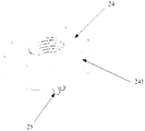
- FIG. 2a is a partial structural diagram of a service robot according to an embodiment of the present invention.
- 2b is a partial structural diagram of a service robot according to an embodiment of the present invention.
- 2c is a schematic structural view of a base of a service robot according to an embodiment of the present invention.
- 3a is a schematic structural view of a pulley retracting state of a service robot according to an embodiment of the present invention
- FIG. 3b is a schematic structural view showing a state in which a pulley of a service robot is extended according to an embodiment of the present invention
- FIG. 4 is a flow chart of a control method of a service robot according to an embodiment of the present invention.
- the design concept of the present invention is: for the prior art, the pulley of the service robot cannot be automatically retracted, the working position is single, and the flexibility is poor.
- the present invention provides a service machine capable of automatically retracting the pulley.
- the service robot can use the set motor drive mechanism to move according to the user's use requirements, and then drive the pulley fixedly connected with the transmission mechanism to be retracted into the robot base or extended out of the base to achieve stable placement to the desktop. Or the effect of scrolling on the ground.
- the service robot 10 includes a main body 101 and a base 102.
- a motor 1021, a transmission mechanism 1022 and a pulley 1023 are disposed in the inner cavity of the base 102.
- the transmission mechanism 1022 is respectively connected to the motor 1021 and the pulley 1023, and the pulley 1023 is disposed below the transmission mechanism 1022.
- the inner cavity of the base 102 has a transmission mechanism 1022. Space for up and down movement;
- the transmission mechanism 1022 is moved in the inner cavity of the base 102 according to a predetermined stroke, and the transmission mechanism 1022 is moved to drive the pulley 1023, so that the pulley 1023 can be retracted into the inner cavity of the base 102 or protruded to the base. 102 outside the lumen.
- a transmission mechanism respectively connected to the motor and the pulley is disposed, and a space for the movement of the transmission mechanism is reserved in the base, so that when the motor is started, the motor drive transmission mechanism can be predetermined according to the motor.
- the stroke moves in the inner cavity of the base, thereby driving the pulley to change the displacement, so that the pulley can be retracted into the inner cavity of the base, thereby conveniently working stably on the plane such as the desktop, or extending out of the inner cavity of the base. Therefore, it is convenient to roll and move in the plane such as the ground, which satisfies the diversified use requirements of users and improves the competitiveness of the products.
- the main function of the transmission mechanism in this embodiment is to drive the pulley disposed under the transmission mechanism to move up and down in the inner cavity of the base under the driving of the motor, thereby realizing the pulley to be retracted into the inner cavity of the base. Or the beneficial effect of sticking out of the inner cavity of the base.
- the transmission mechanism of the embodiment of the present invention can have various implementations, such as a crank slider structure and a ball screw structure. A preferred transmission mechanism employed in the present invention will be described in detail below through the second embodiment.
- the service robot in this embodiment includes: a motor 21 and a transmission mechanism,
- the transmission mechanism comprises: a screw 23 and a nut 24 matched with the screw 23; the screw 23 is fixedly connected with the motor 21, and the pulley 25 is mounted on the lower end surface of the nut 24, the inner cavity of the base 26 is cylindrical; the side of the nut 24 is provided with a guide After the slot 241 is inserted into the slot 241, the nut 24 can only move up and down along the axial direction of the screw 23;
- control screw 23 rotates, and the screw 23 rotates, and the nut 24 is moved up and down, thereby driving the pulley 25 on the nut 24 to be received in the inner cavity of the base 26 or protruding out of the inner cavity of the base 26.
- first limiting member 22 and the second limiting member 262 are further disposed in the inner cavity of the service robot;
- the first limiting member 22 is in the shape of a hollow disk, and the upper end portion of the screw 23 is fitted through the hollow portion of the first limiting member 22 and the first limiting member 22;
- the second limiting member 262 is annular and is formed by extending a predetermined width of the inner surface of the inner cavity of the base 26 inwardly and horizontally.
- the motion control process of the service robot of this embodiment is: after the motor 21 is started according to the command input by the user, according to the first preset direction (eg, forward direction), the driving screw 23 rotates to drive the nut 24 and the pulley 25 along The screw 23 moves axially upward.
- the motor 21 stops rotating; when the motor 21 receives the starting command again, according to the second preset direction (eg, the reverse direction) Rotating, the driving screw 23 rotates to drive the nut 24 and the pulley 25 to move axially downward along the screw 23.
- the motor 21 stops rotating.
- the side surface of the nut 24 (ie, the outer circumferential surface of the nut) is uniformly provided with four guiding grooves 241; correspondingly, the inner surface of the inner cavity of the base 26 that is in contact with the nut 24 is evenly disposed.
- the anti-rotation projections of the four posts 261 are mounted, and the anti-rotation projections are inserted into the post 261 to be engaged with the guide grooves 241 on the nut 24.
- the reason why the guide groove is arranged on the nut and cooperates with the column provided on the base is to prevent the nut from rotating horizontally in the inner cavity of the base, and does not move upward or downward along the axial direction of the screw, so that the pulley can not be retracted or Extend the effect of the pulley.
- the transmission mechanism of the embodiment adopts a screw and a nut, and the transmission mechanism of the two is matched, that is, the pulley provided on the lower end surface of the nut is retracted into the inner cavity of the base by the cooperation of the screw and the nut or Extends to the outside of the base cavity.
- the service robot of the embodiment of the invention can support dual use. Specifically, when the pulley is retracted into the inner cavity of the base, the robot can be fixedly placed on a plane (such as a table top or a ground), and secondly, the pulley is extended to the end. The robot inside the cavity can be used for rolling movement.
- such a service robot of the present embodiment includes a body (not shown in Figures 3a, 3b) and a base 31. It should be noted that, in this embodiment, the main body and the base of the service robot may be an integral structure.
- a control button 32 is disposed on a surface visible to the user on the main body of the service robot.
- the control button 32 is connected to the motor 310 via a wire 33.
- the control button 32 receives a start command input by the user and transmits a start command to the motor 310, and a screw is disposed in the base 31. 314 and the nut 312, the screw 314 and the nut 312 cooperate with each other.
- the nut 312 is disposed under the pulley 313.
- the upper limit member is also disposed in the base, that is, the first limiting member 311, and the lower limit member, that is, the second limiting member. 315.
- the pulley is once stowed or lowered
- the nut 312 is restricted from rotating by the cooperation of the guide groove provided on the side surface and the anti-rotation protrusion of the base into which the column is inserted, so that it can only be axially along the screw 314.
- the motor 310 stops rotating, so that the pulley 313 is completely received into the inner cavity of the base as shown in Fig. 3a.
- the whole robot can be fixedly placed on the table.
- the control button 32 is pressed again, the motor 310 is reversed, and the nut 312 and the pulley 313 move axially downward along the screw 314 when the stroke reaches a predetermined distance (such as 25).
- the millimeter is stopped (ie, the rotation is stopped)
- the pulley 313 is exposed outside the inner cavity of the base, as shown in Fig. 3b, so that the service robot can be placed on the ground to roll to change the working position.
- the cavity of the base can be seen as an inner hollow structure. This design ensures that sufficient space 316 is left to facilitate the up and down movement of the pulley 313.
- the first stroke switch and the second stroke switch provided in the motor 310 can be utilized to specifically control the movement stroke of the nut.
- the motor 310 receives the start command sent by the control button 32 and rotates forward.
- the drive screw 314 rotates to drive the nut 312 and the pulley 313 to move upward along the screw 314.
- the motor 310 stops rotating; when the motor 310 receives the start command sent by the control button 32 again, it rotates in the reverse direction, and the driving screw 314 rotates to drive the nut 312 and the pulley 313 to move downward along the screw 314, when the nut 312 moves downward.
- the motor 310 stops rotating. It can be understood that the setting position of the stroke switch can be adjusted as needed to meet the needs of practical applications.
- control mode is also provided in this embodiment.
- the tripping or lowering of the pulley is taken as an example.
- the control button 32 is pressed once, the motor 310 rotates forward, and the nut 312 and the pulley 313 are axially along the screw 314.
- the motor 310 stops rotating, and the pulley 313 is completely received into the base cavity, as shown in FIG. 3a. At this point, the robot can stably place the desktop work.
- the motor 310 is reversed, so that the nut 312 and the pulley 313 move axially downward along the screw 314, and when the nut moves to the lower limit member of the body (ie, the second limit member 315), the machine stops. At this time, the pulley 313 is exposed to the inner cavity of the base of the service robot. As shown in FIG. 3b, the service robot can be placed on the ground rolling work, which satisfies the use requirement of changing the working position at any time.
- a mechanical manner and a circuit manner are provided to control the motion stroke of the pulley.
- the person skilled in the art can select according to the needs, and can set the movement stroke of the pulley according to the actual situation, for example, control the specific position of the pulley to be placed in the inner cavity, or control the distance that the pulley extends out of the inner cavity, There is no limit to this.
- the pulley 313 is a fixed caster or a movable caster (also called a universal caster), and the number of the pulleys 313 is at least one. In practical applications, the number of pulleys can be set as needed, for example, three pulleys are provided, which is not limited.
- the service robot of the embodiment of the present invention has the following advantages: First, the wheel of the service robot can be automatically retracted, and when the service robot needs to be placed on the desktop, the wheel can be stowed to prevent the service robot from sliding on the desktop. Secondly, when the pulley of the service robot adopts the universal wheel, it can rotate 360 degrees with respect to the main body of the robot, and the flexibility of rolling is ensured when used on the floor. Finally, after the pulley of the robot of the present invention extends out of the inner cavity, the server can also be prevented by a preset fixing device on the pulley. The player slides freely.
- FIG. 4 is a flowchart of a control method of a service robot according to an embodiment of the present invention. Referring to FIG. 4, the method includes:
- Step S41 a motor, a transmission mechanism and a pulley are arranged in the inner cavity of the base of the service robot, the transmission mechanism is respectively connected with the motor and the pulley, and the pulley is disposed under the transmission mechanism; the transmission mechanism is left in the inner cavity of the base Space for up and down movement;
- Step S42 the motor is driven to move in the inner cavity of the base according to a predetermined stroke after the start of the motor, and the transmission mechanism drives the pulley at the same time, so that the pulley can be retracted into the inner cavity of the base or protrude into the inner cavity of the base. outer.
- the setting of the transmission mechanism in the inner cavity of the base of the service robot in step S41 includes:
- the screw is fixedly connected with the motor, and a pulley is mounted on the lower end surface of the nut, and the inner cavity of the base is cylindrical; a guiding groove is arranged on the side of the nut, and the column is inserted into the guiding groove, so that the nut can only move up and down along the axial direction of the screw.
- the driving screw rotates, and the screw rotates to drive the nut up and down, and then the pulley on the nut is brought into the inner cavity of the base or protrudes out of the inner cavity of the base.
- step S42 after the motor is started, the driving screw rotates, and the screw rotates while driving the nut up and down, thereby driving the pulley on the nut to be retracted into the inner cavity of the base or protruding out of the inner cavity of the base.
- the driving screw rotates to drive the nut and the pulley to move upward along the screw axis, and when the nut moves upward to trigger the first
- the motor stops rotating; when the motor starts again, it rotates according to the second preset direction, and the driving screw rotates to drive the nut and the pulley to move downward along the screw axis.
- the motor stops rotating;
- the first limiting member and the second limiting member are disposed in the inner cavity of the base; when the motor is started, rotating according to the first preset direction, the driving screw rotates to drive the nut and the pulley to move upward along the screw axis, and when the nut moves upward When the position of the first limiting member is reached, the motor stops rotating; when the motor is started again, it rotates according to the second preset direction, and the driving screw rotates to drive the nut and the pulley to move downward along the screw axis, when the nut moves downward to When the position of the second limit member is reached, the motor stops rotating.
- the transmission mechanism is set in the service robot and the pulley and the motor are connected by the transmission mechanism, and then the movement of the transmission mechanism is driven by the motor to drive the pulley to realize the effect of extending the pulley out of the robot base and retracting into the base.
- the service robot of the embodiment of the present invention moves up and down in the inner cavity of the base by the motor control transmission mechanism, so that the pulley disposed under the transmission mechanism can be retracted into the inner cavity of the base or protruded. Outside the inner cavity of the base. Since the pulley of the service robot of the embodiment can be automatically retracted, the service robot can be stably placed on a plane such as a desktop, or can be placed on the ground to work in a rolling manner, which satisfies the use requirements of the user in different scenarios. Increase the competitiveness of service robots.
- the present invention also provides a method for implementing a service robot for implementing the service robot of the embodiment of the present invention.
Landscapes
- Engineering & Computer Science (AREA)
- Robotics (AREA)
- Mechanical Engineering (AREA)
- Automation & Control Theory (AREA)
- Manipulator (AREA)
- Toys (AREA)
Abstract
一种服务机器人及其控制方法,该服务机器人包括:主体(101)和底座(102);底座(102)的内腔中设置有电机(1021)、传动机构(1022)以及滑轮(1023),传动机构(1022)分别连接电机(1021)和滑轮(1023),且滑轮(1023)设置在传动机构(1022)的下方;底座(102)的内腔中具有供传动机构(1022)上下运动的空间;电机(1021)启动后,按照预定的行程驱动传动机构在底座(102)的内腔中运动,传动机构(1022)运动的同时带动滑轮(1023),使得滑轮(1023)能够收放到底座(102)的内腔中或伸出到底座(102)的内腔外。这种服务机器人可以自动收放滑轮,从而工作时可以静止放置在桌面上,也可以在地面滚动移动,提高了服务机器人的竞争力和用户体验。
Description
本发明涉及机器人技术领域,具体涉及一种服务机器人及其控制方法。
发明背景
随着社会经济的发展,室内机器人成为越来越多的老人和小孩家居陪护的首选。然而目前的机器人结构复杂,操作繁琐,工作位置固定,无法调整,灵活性差。因此,服务机器人的用户体验亟待优化。
发明内容
有鉴于此,本发明提供了一种服务机器人及其控制方法,以解决现有的服务机器人工作位置固定,无法调整,灵活性差的问题。
根据本发明的一个方面,提供了一种服务机器人,该服务机器人包括:主体和底座;
底座的内腔中设置有电机、传动机构以及滑轮,传动机构分别连接电机和滑轮,且滑轮设置在传动机构的下方;底座的内腔中具有供传动机构上下运动的空间;
电机启动后,按照预定的行程驱动传动机构在底座的内腔中运动,传动机构运动的同时带动滑轮,使得滑轮能够收放到底座的内腔中或伸出到底座的内腔外。
可选地,传动机构包括:螺杆以及与螺杆相配合的螺母;
螺杆与电机固定连接,螺母的下端面上安装滑轮,
底座的内腔为圆柱形;
螺母的侧面设有导向槽,导向槽中插装柱子后,螺母只能沿螺杆轴向上下运动;
电机启动后,驱动螺杆旋转,螺杆旋转的同时带动螺母上下运动,进而带动螺母上的滑轮收放到底座的内腔中或伸出到底座的内腔外。
可选地,服务机器人的主体上设置有控制按钮,控制按钮通过导线连接至电机,控制按钮接收用户输入的启动指令并将启动指令发送至电机。
可选地,电机中设置有第一行程开关和第二行程开关,
电机收到控制按钮发送的启动指令后,按照第一预设方向转动,驱动螺杆转动进而带动螺母和滑轮沿螺杆轴向向上运动,当螺母向上运动到触发第一行程开关时,电机停止转动;
当电机再次收到控制按钮发送的启动指令后,按照第二预设方向转动,驱动螺杆转动进而带动螺母和滑轮沿螺杆轴向向下运动,当螺母向下运动到触发第二行程开关时,电机停止转动。
可选地,该服务机器人的内腔中还设有第一限位件和第二限位件;
第一限位件为空心圆盘状,螺杆的上端部穿过第一限位件的空心部与第一限位件套装在一起;
第二限位件为环状,且由底座内腔的下表面向内水平延伸预定宽度而形成。
可选地,电机收到控制按钮发送的启动指令后,按照第一预设方向转动,驱动螺杆转动进而带动螺母和滑轮沿螺杆轴向向上运动,当螺母向上运动到第一限位件的位置时,电机停止转动;
当电机再次收到控制按钮发送的启动指令后,按照第二预设方向转动,驱动螺杆转动进而带动螺母和滑轮沿螺杆轴向向下运动,当螺母向下运动到第二限位件的位置时,电机停止转动。
可选地,螺母的侧面均匀设有多个导向槽;
滑轮为固定脚轮或活动脚轮,且滑轮的数量至少为一个。
根据本发明的另一个方面,提供了一种服务机器人的控制方法,该方法包括:在服务机器人的底座的内腔中设置电机、传动机构以及滑轮,将传动机构分别与电机和滑轮连接,且将滑轮设置在传动机构的下方;底座的内腔中留出供传动机构上下运动的空间;
利用电机在启动后按照预定的行程驱动传动机构在底座的内腔中运动,传动机构运动的同时带动滑轮,使得滑轮能够收放到底座的内腔中或伸出到底座的内腔外。
可选地,在服务机器人的底座的内腔中设置传动机构包括:
在服务机器人的底座的内腔中设置螺杆以及与螺杆相配合的螺母;
将螺杆与电机固定连接,在螺母的下端面上安装滑轮,
底座的内腔为圆柱形;
在螺母的侧面设导向槽,导向槽中插装柱子后,使得螺母只能沿螺杆轴向上下运动;
利用电机启动后,控制螺杆旋转,螺杆旋转的同时带动螺母上下运动,进而带动螺母上的滑轮收放到底座的内腔中或伸出到底座的内腔外。
可选地,利用电机启动后,控制螺杆旋转,螺杆旋转的同时带动螺母上下运动,进而带动螺母上的滑轮收放到底座的内腔中或伸出到底座的内腔外包括:
利用电机中的第一行程开关和第二行程开关,当电机启动后,按照第一预
设方向转动,驱动螺杆转动进而带动螺母和滑轮沿螺杆轴向向上运动,当螺母向上运动到触发第一行程开关时,电机停止转动;
当电机再次启动后,按照第二预设方向转动,驱动螺杆转动进而带动螺母和滑轮沿螺杆轴向向下运动,当螺母向下运动到触发第二行程开关时,电机停止转动;
或者,
在底座内腔中设置第一限位件和第二限位件;
当电机启动后,按照第一预设方向转动,驱动螺杆转动进而带动螺母和滑轮沿螺杆轴向向上运动,当螺母向上运动到第一限位件的位置时,电机停止转动;
当电机再次启动后,按照第二预设方向转动,驱动螺杆转动进而带动螺母和滑轮沿螺杆轴向向下运动,当螺母向下运动到第二限位件的位置时,电机停止转动。
本发明的有益效果是:本发明的这种服务机器人,通过电机驱动传动机构在底座的内腔中上下运动,从而使得设置在传动机构下方的滑轮能够收放到底座的内腔中或伸出到底座的内腔外。由于本实施例的这种服务机器人的滑轮可以自动收放,从而既可以被稳定放置在桌面等平面上进行工作,也可以被放置到地面上滚动工作,满足了用户不同场景下的使用需求,提高了服务机器人的竞争力。另外,本发明还提供了一种服务机器人的实现方法,用于实现本发明实施例的这种服务机器人。
附图简要说明
图1是本发明一个实施例的一种服务机器人的框图;
图2a是本发明一个实施例的一种服务机器人的部分结构示意图;
图2b是本发明一个实施例的一种服务机器人的部分结构示意图;
图2c是本发明一个实施例的一种服务机器人的底座的结构示意图;
图3a是本发明一个实施例的一种服务机器人的滑轮收起状态的结构示意图;
图3b是本发明一个实施例的一种服务机器人的滑轮伸出状态的结构示意图;
图4是本发明一个实施例的一种服务机器人的控制方法的流程图。
实施本发明的方式
本发明的设计构思是:针对现有技术中,服务机器人的滑轮不能自动收放,工作位置单一、灵活性差的问题,本发明提供一种可以自动收放滑轮的服务机
器人,该服务机器人可根据用户的使用需求,利用设置的电机驱动传动机构运动,进而驱动与传动机构固定连接的滑轮被收放到机器人底座内或伸出到底座外,实现稳定放置到桌面或在地面滚动移动的效果。
实施例一
图1是本发明一个实施例的一种服务机器人的框图,参见图1,该服务机器人10包括:主体101和底座102;
底座102的内腔中设置有电机1021、传动机构1022以及滑轮1023,传动机构1022分别连接电机1021和滑轮1023,且滑轮1023设置传动机构1022的下方;底座102的内腔中具有供传动机构1022上下运动的空间;
电机1021启动后,按照预定的行程驱动传动机构1022在底座102的内腔中运动,传动机构1022运动的同时带动滑轮1023,使得滑轮1023能够收放到底座102的内腔中或伸出到底座102的内腔外。
由此可见,本发明实施例中,通过设置与电机和滑轮分别连接的传动机构,并在底座中预留供传动机构运动的空间,从而当电机启动后,可以通过电机驱动传动机构按照预定的行程在底座的内腔中运动,进而带动滑轮改变位移,使得滑轮既能够被收放至底座的内腔中,从而方便稳定放置到桌面等平面上工作,也可以伸出到底座的内腔外,从而方便在地面等平面滚动移动工作,满足了用户的多样化使用需求,提升了产品的竞争力。
需要说明的是,本实施例中的传动机构的主要作用是,在电机的驱动下带动设置在传动机构下方的滑轮在底座内腔中上下运动,从而实现将滑轮收放到底座的内腔中或伸出到底座的内腔外的有益效果。本发明实施例的传动机构可以有多种实现方式,例如,曲柄滑块结构、滚珠丝杠结构。以下通过实施例二对本发明采用的一种优选的传动机构进行详细说明。
实施例二
参见图2a至图2c,本实施例中的这种服务机器人包括:电机21和传动机构,
传动机构包括:螺杆23以及与螺杆23相配合的螺母24;螺杆23与电机21固定连接,螺母24的下端面上安装滑轮25,底座26的内腔为圆柱形;螺母24的侧面设有导向槽241,导向槽241中插装柱子261后,螺母24只能沿螺杆23轴向上下运动;
电机21启动后,控制螺杆23旋转,螺杆23旋转的同时带动螺母24上下运动,进而带动螺母24上的滑轮25收放到底座26的内腔中或伸出到底座26的内腔外。
本实施例中,该服务机器人的内腔中还设有第一限位件22和第二限位件262;
参见图2a,第一限位件22为空心圆盘状,螺杆23的上端部穿过第一限位件22的空心部与第一限位件22套装在一起;
第二限位件262为环状,且由底座26的内腔的下表面向内水平延伸预定宽度而形成。
本实施例的这种服务机器人的运动控制过程为:电机21根据用户输入的指令启动后,按照第一预设方向(如,正向)转动,驱动螺杆23转动进而带动螺母24和滑轮25沿螺杆23轴向向上运动,当螺母24向上运动到第一限位件22的位置时,电机21停止转动;当电机21再次收到启动指令后,按照第二预设方向(如,反方向)转动,驱动螺杆23转动进而带动螺母24和滑轮25沿螺杆23轴向向下运动,当螺母24向下运动到第二限位件262的位置时,电机21停止转动。
参见图2b,本实施例中,螺母24的侧面(即螺母的外圆周面)均匀设置了四个导向槽241;相应的,底座26的内腔中与螺母24接触的内表面上均匀设置有安装了四个柱子261的防旋凸起,这些防旋凸起中插入柱子261后能和螺母24上的导向槽241卡紧。可以理解,之所以在螺母上设置导向槽并与底座上设置的柱子配合是为了防止螺母在底座内腔中水平转动,而不沿着螺杆轴向向上或向下运动进而无法实现收放滑轮或伸出滑轮的效果。
由上可知,本实施例的传动机构采用的是螺杆和螺母,利用两者配合的传动方式,即,通过螺杆和螺母的配合,将螺母下端面上设置的滑轮收放到底座内腔中或伸出到底座内腔外。使得本发明实施例的服务机器人能够支持两用,具体的,一是,滑轮收放到底座内腔中时机器人可固定放置在平面(如桌面、地面)上使用,二是,滑轮伸出到底座内腔外机器人时可滚动移动使用。
实施例三
本实施例中重点对服务机器人的滑轮处于不同状态下的结构进行说明,其他内容参见本发明的其他实施例。
结合图3a和图3b,本实施例的这种服务机器人包括主体(图3a、3b中未示出)和底座31。需要说明的是,本实施例中,服务机器人的主体和底座可为一体结构。
在服务机器人的主体上用户可见的面上设置控制按钮32,控制按钮32通过导线33连接至电机310,控制按钮32接收用户输入的启动指令并将启动指令发送至电机310,底座31中设置螺杆314和螺母312,螺杆314和螺母312相互配合,螺母312的下方设置有滑轮313,底座中还设置了上限位件,即第一限位件311,以及下限位件,即第二限位件315。
这里,以滑轮的一次收起或放下为例进行说明:螺母312因侧面上设置的导向槽与底座的插装了柱子的防旋凸起的配合限制了转动,所以只能沿螺杆314轴向上下运动。按下一次控制按钮32,电机310正转,螺母312和滑轮313沿
螺杆314轴向向上运动,当螺母312和滑轮313行程向上达到预定距离(如25毫米)时,电机310停止转动,这样滑轮313被全部收进了底座内腔体中,如图3a所示。此时机器人整机可固定放置在桌面上工作,当再次按下控制按钮32时,电机310反转,螺母312和滑轮313沿螺杆314轴向向下运动,当行程达到预定距离时(如25毫米)时停机(即,停止转动),此时,滑轮313露出底座的内腔外,如图3b所示,这样,服务机器人可放置在地面滚动以改变工作位置。如图3b所示当螺母312和滑轮313伸出底座内腔后可以看到底座的腔体为内空结构,这样的设计保证了留出足够的空间316方便滑轮313上下运动。
这种控制方式下,可以利用电机310中设置的第一行程开关和第二行程开关来具体控制螺母的运动行程。例如,电机310收到控制按钮32发送的启动指令后正向转动,驱动螺杆314转动进而带动螺母312和滑轮313沿螺杆314轴向向上运动,当螺母312向上运动到触发第一行程开关时,电机310停止转动;当电机310再次收到控制按钮32发送的启动指令后按照反方向转动,驱动螺杆314转动进而带动螺母312和滑轮313沿螺杆314轴向向下运动,当螺母312向下运动到触发第二行程开关时,电机310停止转动。可以理解,行程开关的设置位置可以根据需要进行调整,以满足实际应用需求。
此外,本实施例中还提供了另一种控制方式,这里以滑轮的一次收起或放下为例说明:按下一次控制按钮32,电机310正转,螺母312和滑轮313沿螺杆314轴向向上运动,当行程向上贴近机体上面板(即,第一限位件311)时,电机310停止转动,滑轮313全部收进底座腔体中,如图3a所示。此时机器人整机可稳定放置桌面工作。再次按下控制按钮32时,电机310反转,使得螺母312和滑轮313沿螺杆314轴向向下运动,当螺母运动到贴近机体下部限位件时(即第二限位件315)停机,这时滑轮313露出服务机器人的底座的内腔,如图3b所示,服务机器人可放置地面滚动工作,满足了随时变换工作位置的使用需求。
需要说明的是,本实施例中提供了一种机械方式和一种电路方式来控制滑轮的运动行程。实际应用过程中,本领域技术人员可以根据需要进行选择,并且可以根据实际情况设置滑轮的运动行程,例如,控制滑轮收放到内腔中的具体位置,或者控制滑轮伸出内腔的距离,对此不作限制。
本实施例中,滑轮313为固定脚轮或活动脚轮(也称万向轮),且滑轮313的数量至少为一个。实际应用中可根据需要设置滑轮的数量,例如设置三个滑轮,对此不作限制。
由此,本发明实施例的这种服务机器人具有如下优点:首先,服务机器人的轮子可自动收放,当服务机器人需要放在桌面使用时,可收起轮子,防止服务机器人在桌面上滑动。其次,当服务机器人的滑轮采用万向轮时,可相对机器人主体360度转动,在地板上使用时保证了滚动的灵活性。最后,本发明的机器人的滑轮伸出内腔后,还可通过在滑轮上预设的固定装置,防止服务器机
器人随意滑动。
实施例四
本发明的实施例还提供了一种服务机器人的控制方法,图4是本发明一个实施例的一种服务机器人的控制方法的流程图,参见图4,该方法包括:
步骤S41,在服务机器人的底座的内腔中设置电机、传动机构以及滑轮,将传动机构分别与电机和滑轮连接,且将滑轮设置在传动机构的下方;底座的内腔中留出供传动机构上下运动的空间;
步骤S42,利用电机在启动后按照预定的行程驱动传动机构在底座的内腔中运动,传动机构运动的同时带动滑轮,使得滑轮能够收放到底座的内腔中或伸出到底座的内腔外。
本实施例中,步骤S41中的在服务机器人的底座的内腔中设置传动机构包括:
在服务机器人的底座的内腔中设置螺杆以及与螺杆相配合的螺母;
将螺杆与电机固定连接,在螺母的下端面上安装滑轮,底座的内腔为圆柱形;在螺母的侧面设导向槽,导向槽中插装柱子后,使得螺母只能沿螺杆轴向上下运动;利用电机启动后,驱动螺杆旋转,螺杆旋转的同时带动螺母上下运动,进而带动螺母上的滑轮收放到底座的内腔中或伸出到底座的内腔外。
本实施例中,步骤S42,利用电机启动后,驱动螺杆旋转,螺杆旋转的同时带动螺母上下运动,进而带动螺母上的滑轮收放到底座的内腔中或伸出到底座的内腔外包括:
利用电机中的第一行程开关和第二行程开关,当电机启动后,按照第一预设方向转动,驱动螺杆转动进而带动螺母和滑轮沿螺杆轴向向上运动,当螺母向上运动到触发第一行程开关时,电机停止转动;当电机再次启动后,按照第二预设方向转动,驱动螺杆转动进而带动螺母和滑轮沿螺杆轴向向下运动,当螺母向下运动到触发第二行程开关时,电机停止转动;
或者,
在底座内腔中设置第一限位件和第二限位件;当电机启动后,按照第一预设方向转动,驱动螺杆转动进而带动螺母和滑轮沿螺杆轴向向上运动,当螺母向上运动到第一限位件的位置时,电机停止转动;当电机再次启动后,按照第二预设方向转动,驱动螺杆转动进而带动螺母和滑轮沿螺杆轴向向下运动,当螺母向下运动到第二限位件的位置时,电机停止转动。
由此,通过服务机器人中设置传动机构并利用传动机构连接滑轮和电机,然后利用电机驱动传动机构运动进而带动滑轮运动,实现将滑轮伸出机器人底座和收放到底座中的效果。
需要说明的是,本实施例中的服务机器人的控制方法的实现步骤是与前述服务机器人的工作过程相对应的,因而本实施例的服务机器人的控制方法的实现步骤可以参见本发明前述实施例的相关说明,在此不再赘述。
综上所述,本发明实施例的这种服务机器人,通过电机控制传动机构在底座的内腔中上下运动,从而使得设置在传动机构下方的滑轮能够收放到底座的内腔中或伸出到底座的内腔外。由于本实施例的这种服务机器人的滑轮可以自动收放,从而服务机器人既可以被稳定放置在桌面等平面上工作,也可以被放置到地面上滚动工作,满足了用户不同场景下的使用需求,提高了服务机器人的竞争力。另外,本发明还提供了一种服务机器人的实现方法,用于实现本发明实施例的这种服务机器人。
以上所述仅为本发明的较佳实施例而已,并非用于限定本发明的保护范围。凡在本发明的精神和原则之内所作的任何修改、等同替换、改进等,均包含在本发明的保护范围内。
Claims (12)
- 一种服务机器人,其中,该服务机器人包括:主体(101)和底座(102,26);所述底座(102,26)的内腔中设置有电机(1021,21)、传动机构(1022)以及滑轮(1023,25),所述传动机构(1022)分别连接所述电机(1021,21)和所述滑轮(1023,25),且滑轮(1023,25)设置在所述传动机构(1022)的下方;所述底座(102,26)的内腔中具有供所述传动机构(1022)上下运动的空间;所述电机(1021,21)启动后,按照预定的行程驱动所述传动机构(1022)在所述底座(102,26)的内腔中运动,所述传动机构(1022)运动的同时带动所述滑轮(1023,25),使得所述滑轮(1023,25)能够收放到所述底座(102,26)的内腔中或伸出到所述底座(102,26)的内腔外。
- 根据权利要求1所述的服务机器人,其中,所述传动机构(1022)包括:螺杆(23)以及与所述螺杆(23)相配合的螺母(24);所述螺杆(23)与所述电机(1021,21)固定连接,所述螺母(24)的下端面上安装所述滑轮(1023,25),所述底座(102,26)的内腔为圆柱形;所述螺母(24)的侧面设有导向槽(241),所述导向槽(241)中插装柱子(261)后,所述螺母(24)只能沿所述螺杆(23)轴向上下运动;所述电机(1021,21)启动后,驱动所述螺杆(23)旋转,所述螺杆(23)旋转的同时带动所述螺母(24)上下运动,进而带动螺母(24)上的滑轮(1023,25)收放到所述底座(102,26)的内腔中或伸出到所述底座(102,26)的内腔外。
- 根据权利要求1所述的服务机器人,其中,所述服务机器人的主体(101)上设置有控制按钮(32),所述控制按钮(32)通过导线连接至所述电机(1021,21),所述控制按钮(32)接收用户输入的启动指令并将所述启动指令发送至所述电机(1021,21)。
- 根据权利要求3所述的服务机器人,其中,所述电机(1021,21)中设置有第一行程开关和第二行程开关,所述电机(1021,21)收到所述控制按钮(32)发送的启动指令后,按照第一预设方向转动,驱动所述螺杆(23)转动进而带动所述螺母(24)和所述滑轮(1023,25)沿所述螺杆(23)轴向向上运动,当所述螺母(24)向上运动到触发所述第一行程开关时,所述电机(1021,21)停止转动;当所述电机(1021,21)再次收到所述控制按钮(32)发送的启动指令后, 按照第二预设方向转动,驱动所述螺杆(23)转动进而带动所述螺母(24)和所述滑轮(1023,25)沿所述螺杆(23)轴向向下运动,当所述螺母(24)向下运动到触发所述第二行程开关时,所述电机(1021,21)停止转动。
- 根据权利要求3所述的服务机器人,其中,该服务机器人的内腔中还设有第一限位件(311,22)和第二限位件(315,262);所述第一限位件(311,22)为空心圆盘状,所述螺杆(23)的上端部穿过所述第一限位件(311,22)的空心部与所述第一限位件(311,22)套装在一起;所述第二限位件(315,262)为环状,且由所述底座(102,26)内腔的下表面向内水平延伸预定宽度而形成。
- 根据权利要求5所述的服务机器人,其中,所述电机(1021,21)收到所述控制按钮(32)发送的启动指令后,按照第一预设方向转动,驱动所述螺杆(23)转动进而带动所述螺母(24)和所述滑轮(1023,25)沿所述螺杆(23)轴向向上运动,当所述螺母(24)向上运动到所述第一限位件(311,22)的位置时,所述电机(1021,21)停止转动;当所述电机(1021,21)再次收到所述控制按钮(32)发送的启动指令后,按照第二预设方向转动,驱动所述螺杆(23)转动进而带动所述螺母(24)和所述滑轮(1023,25)沿所述螺杆(23)轴向向下运动,当所述螺母(24)向下运动到第二限位件(315,262)的位置时,所述电机(1021,21)停止转动。
- 根据权利要求3所述的服务机器人,其中,所述电机(1021,21)收到所述控制按钮(32)发出的启动命令后,按照第一预设方向转动,驱动所述螺杆(23)转动进而带动所述螺母(24)和所述滑轮(1023,25)沿所述螺杆(23)轴向向上运动,当向上行程达到预定距离时,所述电机(1021,21)停止转动;当所述电机(1021,21)再次收到所述控制按钮(32)发送的启动指令后,按照第二预设方向转动,驱动所述螺杆(23)转动进而带动所述螺母(24)和所述滑轮(1023,25)沿所述螺杆(23)轴向向下运动,当向下行程达到预定距离时,所述电机(1021,21)停止转动。
- 根据权利要求2所述的服务机器人,其中,所述螺母(24)的侧面均匀设有多个导向槽(241);所述滑轮(1023,25)为固定脚轮或活动脚轮,且所述滑轮(1023,25)的数量至少为一个。
- 一种服务机器人的控制方法,其中,该方法包括:在所述服务机器人的底座(102,26)的内腔中设置电机(1021,21)、传动机构(1022)以及滑轮(1023,25),将所述传动机构(1022)分别与所述电机(1021,21)和所述滑轮(1023,25)连接,且将滑轮(1023,25)设置在所述传动机构(1022)的下方;所述底座(102,26)的内腔中留出供所述传动机构(1022)上下运动的空间;利用所述电机(1021,21)在启动后按照预定的行程驱动所述传动机构(1022)在所述底座(102,26)的内腔中运动,所述传动机构(1022)运动的同时带动所述滑轮(1023,25),使得所述滑轮(1023,25)能够收放到所述底座(102,26)的内腔中或伸出到所述底座(102,26)的内腔外。
- 根据权利要求9所述的方法,其中,在所述服务机器人的所述底座(102,26)的内腔中设置传动机构(1022)包括:在所述服务机器人的所述底座(102,26)的内腔中设置螺杆(23)以及与所述螺杆(23)相配合的螺母(24);将所述螺杆(23)与所述电机(1021,21)固定连接,在所述螺母(24)的下端面上安装所述滑轮(1023,25),所述底座(102,26)的内腔为圆柱形;在所述螺母(24)的侧面设导向槽(241),所述导向槽(241)中插装柱子(261)后,使得所述螺母(24)只能沿所述螺杆(23)轴向上下运动;利用所述电机(1021,21)启动后,驱动所述螺杆(23)旋转,所述螺杆(23)旋转的同时带动所述螺母(24)上下运动,进而带动螺母(24)上的滑轮(1023,25)收放到所述底座(102,26)的内腔中或伸出到所述底座(102,26)的内腔外。
- 根据权利要求10所述的方法,其中,所述利用所述电机(1021,21)启动后,驱动所述螺杆(23)旋转,所述螺杆(23)旋转的同时带动所述螺母(24)上下运动,进而带动螺母(24)上的滑轮(1023,25)收放到所述底座(102,26)的内腔中或伸出到所述底座(102,26)的内腔外包括:利用所述电机(1021,21)中的第一行程开关和第二行程开关,当所述电机(1021,21)启动后,按照第一预设方向转动,驱动所述螺杆(23)转动进而带动所述螺母(24)和所述滑轮(1023,25)沿所述螺杆(23)轴向向上运动,当所述螺母向(24)上运动到触发所述第一行程开关时,所述电机(1021,21)停止转动;当所述电机(1021,21)再次启动后,按照第二预设方向转动,驱动所述螺杆(23)转动进而带动所述螺母(24)和所述滑轮(1023,25)沿所述螺杆(23)轴向向下运动,当所述螺母(24)向下运动到触发所述第二行程开关时,所述电机(1021,21)停止转动。
- 根据权利要求10所述的方法,其中,所述利用电机(1021,21)启动后,驱动所述螺杆(23)旋转,所述螺杆(23)旋转的同时带动所述螺母(24) 上下运动,进而带动螺母(24)上的滑轮(1023,25)收放到所述底座(102,26)的内腔中或伸出到所述底座(102,26)的内腔外包括:在所述底座(102,26)内腔中设置第一限位件(311,22)和第二限位件(315,262);利用所述电机(1021,21)在启动后,按照第一预设方向转动,驱动所述螺杆(23)转动进而带动所述螺母(24)和所述滑轮(1023,25)沿所述螺杆(23)轴向向上运动,当所述螺母(24)向上运动到所述第一限位件(311,22)的位置时,所述电机(1021,21)停止转动;利用所述电机(1021,21)在再次启动后,按照第二预设方向转动,驱动所述螺杆(23)转动进而带动所述螺母(24)和所述滑轮(1023,25)沿所述螺杆(23)轴向向下运动,当所述螺母(24)向下运动到所述第二限位件(315,262)的位置时,所述电机(1021,21)停止转动。
Priority Applications (1)
| Application Number | Priority Date | Filing Date | Title |
|---|---|---|---|
| US16/082,738 US10668615B2 (en) | 2016-04-28 | 2017-04-28 | Service robot and method for controlling same |
Applications Claiming Priority (2)
| Application Number | Priority Date | Filing Date | Title |
|---|---|---|---|
| CN201610280377.6A CN105818149B (zh) | 2016-04-28 | 2016-04-28 | 一种服务机器人及其控制方法 |
| CN201610280377.6 | 2016-04-28 |
Publications (1)
| Publication Number | Publication Date |
|---|---|
| WO2017186154A1 true WO2017186154A1 (zh) | 2017-11-02 |
Family
ID=56528979
Family Applications (1)
| Application Number | Title | Priority Date | Filing Date |
|---|---|---|---|
| PCT/CN2017/082323 Ceased WO2017186154A1 (zh) | 2016-04-28 | 2017-04-28 | 一种服务机器人及其控制方法 |
Country Status (3)
| Country | Link |
|---|---|
| US (1) | US10668615B2 (zh) |
| CN (1) | CN105818149B (zh) |
| WO (1) | WO2017186154A1 (zh) |
Families Citing this family (6)
| Publication number | Priority date | Publication date | Assignee | Title |
|---|---|---|---|---|
| CN105818149B (zh) | 2016-04-28 | 2018-11-23 | 歌尔股份有限公司 | 一种服务机器人及其控制方法 |
| CN108564823B (zh) * | 2018-01-25 | 2019-10-25 | 山西宇翔信息技术有限公司 | 一种便于儿童操作的儿童教育机器人 |
| US10828780B2 (en) * | 2018-04-13 | 2020-11-10 | The Boeing Company | Airplane passenger service robot |
| WO2020171268A1 (ko) * | 2019-02-22 | 2020-08-27 | 엘지전자 주식회사 | 로봇 |
| US20230278230A1 (en) * | 2020-08-04 | 2023-09-07 | Lg Electronics Inc. | Tray and robot having same |
| CN112847363B (zh) * | 2021-01-06 | 2022-02-15 | 中国人民解放军国防科技大学 | 月面舱外辅助作业机器人及其操控方法 |
Citations (7)
| Publication number | Priority date | Publication date | Assignee | Title |
|---|---|---|---|---|
| PL389985A1 (pl) * | 2009-12-21 | 2011-07-04 | Przemysłowy Instytut Automatyki i Pomiarów PIAP | Kołowa platforma jezdna robota mobilnego |
| CN104149546A (zh) * | 2014-08-12 | 2014-11-19 | 太仓兴锋脚轮有限公司 | 脚轮 |
| CN104440854A (zh) * | 2013-09-12 | 2015-03-25 | 上海尧华科技发展有限公司 | 一种可自动收缩滚轮的工作台滚轮装置 |
| CN204567134U (zh) * | 2015-04-22 | 2015-08-19 | 湖州健泰食品有限公司 | 自动定位轮 |
| CN105415344A (zh) * | 2015-12-28 | 2016-03-23 | 昆明万锐鹍鹏机电工程技术有限公司 | 龙门式箱形物件装卸车机器人 |
| CN105818149A (zh) * | 2016-04-28 | 2016-08-03 | 歌尔声学股份有限公司 | 一种服务机器人及其控制方法 |
| CN205766169U (zh) * | 2016-04-28 | 2016-12-07 | 歌尔股份有限公司 | 一种服务机器人 |
Family Cites Families (6)
| Publication number | Priority date | Publication date | Assignee | Title |
|---|---|---|---|---|
| CN2125513U (zh) * | 1992-04-07 | 1992-12-23 | 黄国金 | 收藏式万向脚轮 |
| CN201002479Y (zh) * | 2006-12-18 | 2008-01-09 | 罗华西 | 一种可水平调节脚轮 |
| US9020636B2 (en) * | 2010-12-16 | 2015-04-28 | Saied Tadayon | Robot for solar farms |
| CN202080062U (zh) * | 2011-05-04 | 2011-12-21 | 广东海洋大学 | 椅凳伸缩脚轮装置 |
| CA3107876C (en) * | 2013-05-23 | 2022-11-29 | Q-Bot Limited | Method of covering a surface of a building and robot therefor |
| CN203818924U (zh) * | 2014-05-14 | 2014-09-10 | 哈尔滨学院 | 三角钢琴琴腿暗藏式脚轮结构 |
-
2016
- 2016-04-28 CN CN201610280377.6A patent/CN105818149B/zh active Active
-
2017
- 2017-04-28 US US16/082,738 patent/US10668615B2/en active Active
- 2017-04-28 WO PCT/CN2017/082323 patent/WO2017186154A1/zh not_active Ceased
Patent Citations (7)
| Publication number | Priority date | Publication date | Assignee | Title |
|---|---|---|---|---|
| PL389985A1 (pl) * | 2009-12-21 | 2011-07-04 | Przemysłowy Instytut Automatyki i Pomiarów PIAP | Kołowa platforma jezdna robota mobilnego |
| CN104440854A (zh) * | 2013-09-12 | 2015-03-25 | 上海尧华科技发展有限公司 | 一种可自动收缩滚轮的工作台滚轮装置 |
| CN104149546A (zh) * | 2014-08-12 | 2014-11-19 | 太仓兴锋脚轮有限公司 | 脚轮 |
| CN204567134U (zh) * | 2015-04-22 | 2015-08-19 | 湖州健泰食品有限公司 | 自动定位轮 |
| CN105415344A (zh) * | 2015-12-28 | 2016-03-23 | 昆明万锐鹍鹏机电工程技术有限公司 | 龙门式箱形物件装卸车机器人 |
| CN105818149A (zh) * | 2016-04-28 | 2016-08-03 | 歌尔声学股份有限公司 | 一种服务机器人及其控制方法 |
| CN205766169U (zh) * | 2016-04-28 | 2016-12-07 | 歌尔股份有限公司 | 一种服务机器人 |
Also Published As
| Publication number | Publication date |
|---|---|
| US20190022850A1 (en) | 2019-01-24 |
| US10668615B2 (en) | 2020-06-02 |
| CN105818149B (zh) | 2018-11-23 |
| CN105818149A (zh) | 2016-08-03 |
Similar Documents
| Publication | Publication Date | Title |
|---|---|---|
| WO2017186154A1 (zh) | 一种服务机器人及其控制方法 | |
| WO2021127937A1 (zh) | 摄像装置、电子设备及电子设备的使用方法 | |
| US1708450A (en) | Dental chair | |
| WO2021127934A1 (zh) | 摄像装置、电子设备及电子设备的使用方法 | |
| CN105743278A (zh) | 一种跑步机扬升驱动装置 | |
| CN205766169U (zh) | 一种服务机器人 | |
| CN113154218B (zh) | 一种显示器支架 | |
| JP3235014U (ja) | スクレーパー回転式麻雀卓 | |
| CN209219402U (zh) | 一种圆桌 | |
| CN214209306U (zh) | 一种舞蹈训练用旋转练习辅助装置 | |
| CN111451832B (zh) | 柔性料仓的料仓结构 | |
| CN112995376A (zh) | 功能模组和电子设备 | |
| CN110043770B (zh) | 一种基于人脸识别的智能互动显示装置及其使用方法 | |
| US20200080566A1 (en) | Self-shaking type USB table fan | |
| CN110876044B (zh) | 投影系统及投影设备的自动开机方法 | |
| CN114950254B (zh) | 一种带球形支撑的锥形混合机及制造方法 | |
| CN218369882U (zh) | 一种家具装饰面板生产用托板出料装置 | |
| CN206436351U (zh) | 一种盘式工作台陶瓷坯胎浮雕雕刻机 | |
| CN207334156U (zh) | 可伸缩立柱锁紧固定机构 | |
| CN205725316U (zh) | 一种跑步机扬升驱动装置 | |
| CN221604251U (zh) | 一种定位装置 | |
| CN212469758U (zh) | 一种3d打印设备的自由度打印基台 | |
| CN108930707B (zh) | 转轴机构、电子设备及控制方法 | |
| CN223894472U (zh) | 一种落地扇 | |
| CN206666030U (zh) | 升降机构和家具 |
Legal Events
| Date | Code | Title | Description |
|---|---|---|---|
| NENP | Non-entry into the national phase |
Ref country code: DE |
|
| 121 | Ep: the epo has been informed by wipo that ep was designated in this application |
Ref document number: 17788806 Country of ref document: EP Kind code of ref document: A1 |
|
| 122 | Ep: pct application non-entry in european phase |
Ref document number: 17788806 Country of ref document: EP Kind code of ref document: A1 |