WO2017183582A1 - 光学特性測定装置 - Google Patents
光学特性測定装置 Download PDFInfo
- Publication number
- WO2017183582A1 WO2017183582A1 PCT/JP2017/015314 JP2017015314W WO2017183582A1 WO 2017183582 A1 WO2017183582 A1 WO 2017183582A1 JP 2017015314 W JP2017015314 W JP 2017015314W WO 2017183582 A1 WO2017183582 A1 WO 2017183582A1
- Authority
- WO
- WIPO (PCT)
- Prior art keywords
- light
- virtual image
- image sensor
- diaphragm
- optical
- Prior art date
- Legal status (The legal status is an assumption and is not a legal conclusion. Google has not performed a legal analysis and makes no representation as to the accuracy of the status listed.)
- Ceased
Links
Images









Classifications
-
- G—PHYSICS
- G01—MEASURING; TESTING
- G01M—TESTING STATIC OR DYNAMIC BALANCE OF MACHINES OR STRUCTURES; TESTING OF STRUCTURES OR APPARATUS, NOT OTHERWISE PROVIDED FOR
- G01M11/00—Testing of optical apparatus; Testing structures by optical methods not otherwise provided for
- G01M11/02—Testing optical properties
- G01M11/0207—Details of measuring devices
-
- G—PHYSICS
- G01—MEASURING; TESTING
- G01M—TESTING STATIC OR DYNAMIC BALANCE OF MACHINES OR STRUCTURES; TESTING OF STRUCTURES OR APPARATUS, NOT OTHERWISE PROVIDED FOR
- G01M11/00—Testing of optical apparatus; Testing structures by optical methods not otherwise provided for
-
- G—PHYSICS
- G02—OPTICS
- G02B—OPTICAL ELEMENTS, SYSTEMS OR APPARATUS
- G02B27/00—Optical systems or apparatus not provided for by any of the groups G02B1/00 - G02B26/00, G02B30/00
- G02B27/02—Viewing or reading apparatus
Definitions
- the present invention relates to a technique for measuring optical characteristics of an exit pupil of a virtual image display device.
- a virtual image projection head mounted display is an example of a virtual image display device, and displays a virtual image of an image displayed on an image display unit (for example, a liquid crystal display) of the head mounted display.
- an image display unit for example, a liquid crystal display
- the human pupil is positioned on the exit pupil of the head mounted display while the head mounted display displays the virtual image, the human can see the virtual image.
- Patent Document 1 discloses an optical characteristic measurement apparatus that can form an image of a measurement object on a two-dimensional sensor and measure the luminance, chromaticity, and the like of the measurement object in two dimensions.
- Patent Document 2 discloses an aperture mirror, an objective lens that forms an image of a measurement target on the aperture mirror, a finder system that displays an image of the measurement target using light reflected by the aperture mirror, and an aperture mirror.
- a luminance meter is disclosed that includes a light receiving element that receives light that has passed through. In this luminance meter, the image to be measured is formed on the aperture mirror and is not formed on the light receiving element.
- the brightness and chromaticity on the exit pupil of the head mounted display should be uniform.
- the optical system provided in the virtual image projection type head-mounted display is complicated, and as a result, the luminance and chromaticity on the exit pupil are not uniform.
- the size of the human pupil changes according to the surrounding brightness. When the surroundings are bright, the pupil is small, and when the surroundings are dark, the pupil is large.
- the range in which the pupil size changes is generally in the range of 2 mm to 7 mm in diameter.
- the exit pupil of a head mounted display is usually larger than the human pupil. For this reason, when the luminance and chromaticity on the exit pupil are not uniform, the luminance and chromaticity of the virtual image appear different when the position of the pupil is moved. Therefore, an apparatus capable of measuring the luminance and chromaticity at each position on the exit pupil of the head mounted display is desired.
- the imaging optical system is configured to display the virtual image composed of light passing through the position of the exit pupil in a state where a virtual image that can be viewed from the position of the exit pupil of the virtual image display apparatus is displayed by the virtual image display apparatus.
- the image is formed at a predetermined position.
- the aperture portion has an opening that is disposed at the predetermined position and allows light constituting a part of the virtual image formed at the predetermined position to pass therethrough.
- the image sensor receives light constituting the part that has passed through the opening and has spread.
- the calculation unit calculates an optical characteristic of each position on the exit pupil using a signal output from the image sensor.
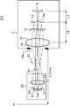
- FIG. 6 is a block diagram showing a configuration of an optical characteristic measuring apparatus according to the first to fifth embodiments. It is a block diagram which shows the structure of the light-receiving part with which the optical characteristic measuring apparatus which concerns on 1st Embodiment is equipped. It is a top view of the exit pupil seen from the direction of the optical axis.
- 1st Embodiment it is explanatory drawing explaining the course of light La.
- 1st Embodiment it is explanatory drawing explaining the course of the light Lb.
- 1st Embodiment it is explanatory drawing explaining the course of the light Lc.
- the embodiments of the present invention include a first embodiment to a fifth embodiment.
- the object measured by these embodiments is a virtual image display device.
- the virtual image display device include a virtual image projection type head mounted display and a virtual image type optical finder.
- the former will be described as an example.
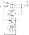
- FIG. 1 is a schematic diagram showing a state in which a human is viewing a virtual image VI displayed by a virtual image projection type head mounted display (hereinafter, HMD) 20.
- HMD virtual image projection type head mounted display
- the HMD 20 includes an image display unit 21 and an optical system 22.
- the image display unit 21 is, for example, a liquid crystal display.
- light La, light Lb, and light Lc are shown.
- the light La, the light Lb, and the light Lc are all light that forms part of an image. Therefore, the light La, the light Lb, and the light Lc become light that constitutes a part of the virtual image VI.
- the light La is light constituting a spot located at the center of the image displayed on the image display unit 21 (virtual image VI displayed by the HMD 20).
- the light Lb is light that constitutes a spot located above the center of the image (virtual image VI) among spots constituting the peripheral portion of the image (virtual image VI displayed by the HMD 20) displayed on the image display unit 21. is there.
- the light Lc is light constituting a spot located below the center of the image (virtual image VI) among spots constituting the peripheral portion of the image (virtual image VI displayed by the HMD 20) displayed on the image display unit 21. It is.
- the optical system 22 generates a virtual image VI of the image displayed on the image display unit 21.
- a single lens is shown as the optical system 22, but the optical system 22 is configured by a number of optical components (aperture, lens, etc.) not shown.
- the exit pupil 23 of the HMD 20 is an image of a diaphragm formed by a lens located on the image side of the diaphragm (in other words, located behind the diaphragm). If the human pupil is positioned on the exit pupil 23 in a state where the HMD 20 displays the virtual image VI, the human can see the virtual image VI.
- FIG. 2 is a block diagram showing a configuration of the optical property measuring apparatus 101 according to the first embodiment.
- FIG. 2 is also a block diagram showing the configuration of the optical characteristic measuring apparatuses 102 to 105 according to the second to fifth embodiments.
- the optical characteristic measurement apparatus 101 according to the first embodiment includes a light receiving unit 1, a control calculation unit 3, an input unit 5, and an output unit 7.
- FIG. 3 is a block diagram illustrating a configuration of the light receiving unit 1 provided in the optical characteristic measuring apparatus 101 according to the first embodiment.
- the optical characteristic measuring device 101 is a device that measures luminance, and is arranged in order along the optical axis Ax, the first diaphragm unit 10, the objective lens 11, the visibility filter 12, the second diaphragm unit 13, and the like.
- a two-dimensional image sensor 14 is provided.
- FIG. 3 light La, light Lb, and light Lc are shown in the light constituting the image displayed on the image display unit 21 of the HMD 20 as in FIG.
- the light constituting the image displayed on the image display unit 21 passes through the exit pupil 23 of the HMD 20 and enters the optical characteristic measuring apparatus 101 from the first diaphragm unit 10.
- the distance L1 between the first diaphragm 10 and the virtual image VI is infinite ( ⁇ )
- the light passing through the position of the exit pupil 23 becomes parallel light.
- the distance L1 is often finite, and the light passing through the position of the exit pupil 23 becomes divergent light.
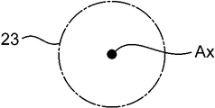
- FIG. 4 is a plan view of the exit pupil 23 viewed from the direction of the optical axis Ax.
- the exit pupil 23 has a circular shape when viewed from the direction of the optical axis Ax (in the case of an axially symmetric optical system).
- the first aperture section 10 has an opening 10a through which light incident on the optical characteristic measuring apparatus 101 passes.
- the first diaphragm unit 10 has a function of regulating light incident on the optical property measuring apparatus 101.
- the objective lens 11 is an example of an imaging optical system, and forms a virtual image VI composed of light that has passed through the position of the exit pupil 23 in a state where the virtual image VI is displayed by the HMD 20 at a predetermined position.
- the distance between the predetermined position and the objective lens 11 is the focal length L2 of the objective lens 11.
- the visibility filter 12 is disposed in the optical path between the objective lens 11 and the second diaphragm 13, and light traveling from the objective lens 11 toward the second diaphragm 13 passes therethrough.
- the visibility filter 12 is a kind of color filter, and is a filter that corrects the sensitivity of the two-dimensional image sensor 14 so as to match the human visibility.
- the position at which the visibility filter 12 is disposed is not limited between the objective lens 11 and the second diaphragm unit 13, but is disposed in the optical path between the first diaphragm unit 10 and the two-dimensional image sensor 14. Can do.
- the second diaphragm 13 functions as a field diaphragm for the objective lens 11.
- squeeze part 13 is arrange
- the objective lens 11 forms a virtual image VI composed of light that has passed through the position of the exit pupil 23 on the second diaphragm 13.
- the light constituting the image displayed on the image display unit 21 passes through the position of the exit pupil 23 and is imaged at the position of the second aperture unit 13.
- the second diaphragm 13 has an opening 13a through which light constituting a part of the virtual image VI passes.
- FIG. 3 shows a case where light constituting a part of the virtual image VI is light La.
- the two-dimensional image sensor 14 is an example of an image sensor, and is arranged at a position separated from the second diaphragm 13 by a predetermined distance L3.
- the light constituting a part of the virtual image VI becomes divergent light after passing through the opening 13 a and is received by the two-dimensional image sensor 14.
- the two-dimensional image sensor 14 receives light that forms a part of the virtual image VI that has passed through the opening 13a and has spread.
- the spread light is not limited to diverging light but may be parallel light.
- the two-dimensional image sensor 14 is, for example, a CCD (Charge Coupled Device) or a CMOS (Complementary MOS), and is an optical sensor having a two-dimensional region as a measurement range.
- control calculation unit 3 is a microcomputer realized by a CPU (Central Processing Unit), a RAM (Random Access Memory), a ROM (Read Only Memory), and the like, and the operation of the optical characteristic measuring apparatus 101. Control necessary for the operation and various calculations (for example, calculation of luminance) are executed.
- CPU Central Processing Unit
- RAM Random Access Memory
- ROM Read Only Memory
- the input unit 5 is a device for inputting commands (commands), data, and the like from the outside to the optical property measuring apparatus 101, and is realized by a keyboard.
- a touch panel may be used as the input unit 5.
- the output unit 7 is a device for outputting commands and data input from the input unit 5 and the calculation results of the control calculation unit 3, and is realized by a display. Note that a printing apparatus such as a printer may be used as the output unit 7.
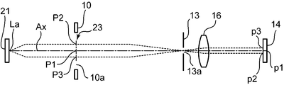
- FIG. 5 is an explanatory diagram illustrating the path of the light La.
- FIG. 6 is an explanatory diagram for explaining the path of the light Lb.
- FIG. 7 is an explanatory diagram for explaining the path of the light Lc.
- some optical components for example, the objective lens 11 shown in FIG. 3 located in the light path are not shown.
- the light La, the light Lb, and the light Lc are parallel light at the position of the exit pupil 23 and are collected at one point at the position of the second aperture unit 13.
- the paths of the light Lb and the light Lc are blocked by the second diaphragm 13, but the light La passes through the opening 13 a and becomes divergent light at the position of the two-dimensional image sensor 14.
- the center of the exit pupil 23 is set as a position P1.
- Two points that define the diameter of the exit pupil 23 are defined as a position P2 and a position P3.
- FIG. 8 is a plan view of the exit pupil 23 viewed from the direction of the optical axis Ax and the light La, the light Lb, and the light Lc viewed from the direction of the optical axis Ax at the position of the exit pupil 23.
- the exit pupil 23, the light La, the light Lb, and the light Lc have a circular shape with the same area in the case of an ideal optical system, and overlap each other (actually May not be circular or may not overlap).
- the light La is divergent light at the position of the two-dimensional image sensor 14, and the divergent light is received by the two-dimensional image sensor 14.
- the luminance distribution of the divergent light corresponds to the luminance distribution of the exit pupil 23.
- the position P1 on the exit pupil 23 corresponds to the position p1 on the two-dimensional image sensor 14, and the position P2 on the exit pupil 23 corresponds to the position p2 on the two-dimensional image sensor 14, and on the exit pupil 23.
- the position P3 corresponds to the position p3 on the two-dimensional image sensor 14. Therefore, the luminance calculated by the control calculation unit 3 shown in FIG.
- the luminance indicates the luminance at the position P2, and the luminance calculated using the light reception signal at the position p3 indicates the luminance at the position P3.
- the control calculation unit 3 is an example of a calculation unit.
- the control calculation unit 3 uses each light reception signal output from the two-dimensional image sensor 14 to output each light on the exit pupil 23. Calculate the brightness of the position.
- the output unit 7 outputs the result of this calculation.
- the light constituting the image displayed on the image display unit 21 passes through the position of the exit pupil 23, and the second aperture stop.
- An image is formed at the position of the portion 13.
- the light (here, the light La) constituting a part of the virtual image VI formed at this position is a parallel light having a predetermined spread at the position of the exit pupil 23.
- This parallel light is light distributed over the entire exit pupil 23 as viewed from the front of the exit pupil 23 (FIG. 8).
- the light constituting the part is light spread at the position of the two-dimensional image sensor 14.
- the inventor uses the light reception signal output from the two-dimensional image sensor 14 that has received this light, and each position on the exit pupil 23 (each on the virtual image VI in the state where the HMD 20 displays the virtual image VI). It was found that the optical properties of the position (not the position) are required.
- the first embodiment is a case where the optical characteristic is luminance. As described above, according to the optical characteristic measuring apparatus 101 according to the first embodiment, the luminance of each position on the exit pupil 23 of the HMD 20 can be measured.
- the brightness distribution on the exit pupil 23 is obtained by the brightness of each position on the exit pupil 23. Since the optical characteristic measuring apparatus 101 according to the first embodiment uses the two-dimensional image sensor 14 as an image sensor, the luminance distribution on the exit pupil 23 is a two-dimensional luminance distribution. In place of the two-dimensional image sensor 14, a line sensor can be used. In the case of a line sensor, since the measurement range is one-dimensional, the luminance at each position on the exit pupil 23 is measured in one dimension instead of two dimensions. Therefore, the luminance distribution on the exit pupil 23 is a one-dimensional luminance distribution.
- FIG. 9 is an explanatory diagram for explaining this.
- FIG. 9 adds a symbol P4 and the like to FIG.
- the optical characteristic measuring apparatus 101 has an exit pupil 23 having a diameter substantially the same as the diameter of the opening 10a of the first diaphragm 10.
- the brightness of each position on the exit pupil 23 can be measured.
- the diameter substantially the same as the diameter of the opening 10a is the diameter of the exit pupil 23 defined by the position P4 and the position P5.
- the position P4 corresponds to the position p4 on the two-dimensional image sensor 14, and the position P5 corresponds to the position p5 on the two-dimensional image sensor 14. Therefore, the luminance calculated by the control calculation unit 3 shown in FIG. 2 using the light reception signal at the position p4 of the two-dimensional image sensor 14 indicates the luminance at the position P4 and is calculated using the light reception signal at the position p5. The luminance indicates the luminance at the position P5.
- the optical characteristic measuring apparatus 101 measures the luminance of each position on the exit pupil 23 for the exit pupil 23 having a slightly smaller diameter than the diameter of the opening 10a. Can do.
- the diameter of the exit pupil 23 of a general HMD 20 is 2 mm to 15 mm. Therefore, it is desirable that the maximum diameter of the exit pupil 23 that can be measured by the optical characteristic measuring apparatus 101 is about 20 mm.
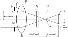
- the focal length L2, the distance L3, and the size of the two-dimensional image sensor 14 for realizing this will be described.
- FIG. 10 is an explanatory diagram for explaining this.
- the height of the exit pupil 23 with respect to the optical axis Ax is H
- the distance on the two-dimensional image sensor 14 with respect to the center of the two-dimensional image sensor 14 is D.
- the focal length L2 the distance L3, the height H, and the distance D, the following Expression 1 is established.
- the height H is 10 mm.
- the focal length L2 is 50 mm and the distance L3 is 9 mm, the distance D is 1.8 mm. Therefore, if the two-dimensional image sensor 14 having a size of 1/3 inch or more is used, the maximum diameter of the exit pupil 23 that can be measured can be set to about 20 mm.
- the size of 1/3 inch means a width of 4.8 mm ⁇ a height of 3.6 mm.
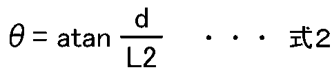
- the measurement angle of the optical property measuring apparatus 101 will be described with reference to FIG.
- the measurement angle ⁇ is expressed by the following formula 2.
- the measurement angle ⁇ is reduced, the luminance distribution of the divergent light received by the two-dimensional image sensor 14 becomes clearer, so that the luminance distribution of the exit pupil 23 is shown more clearly.
- the measurement angle ⁇ decreases, the amount of divergent light received by the two-dimensional image sensor 14 decreases. Therefore, it is necessary to set the measurement angle ⁇ in consideration of these.
- the measurer sets the position of the objective lens 11 in order to form a virtual image VI formed by the light that has passed through the position of the exit pupil 23 on the second diaphragm 13. (Focus).
- the optical characteristic measuring apparatus 101 does not include a finder that allows the measurer to confirm the position of the virtual image VI. Therefore, the measurer sets the position of the objective lens 11 in consideration of the distance L1 between the first diaphragm 10 and the virtual image VI.
- aperture 10a of first diaphragm 10 does not function as an aperture diaphragm (the aperture diaphragm of objective lens 11).
- the light receiving area of each pixel constituting the two-dimensional image sensor 14 functions as an aperture stop. For this reason, even if the position of the objective lens 11 is changed for focusing, the amount of light incident on each pixel constituting the two-dimensional image sensor 14 does not change.
- the luminance of each position on the exit pupil 23 is measured for the light La that forms the center of the image displayed on the image display unit 21 (virtual image VI displayed by the HMD 20).
- a method for measuring the luminance of each position on the exit pupil 23 of the HMD 20 with respect to the light constituting the peripheral portion of the image displayed on the image display unit 21 (virtual image VI displayed by the HMD 20) will be described.
- FIG. 11 is an explanatory diagram for explaining this method.
- the light receiving unit 1 of the optical characteristic measuring apparatus 101 is disposed slightly tilted. When the measurer rotates the light receiving unit 1 or the HMD 20, the luminance of each position on the exit pupil 23 of the HMD 20 can be measured for the light constituting the peripheral portion.
- the light Lc passes through the opening 13 a, diffuses to become divergent light, and is received by the two-dimensional image sensor 14.
- the measurer rotates the light receiving unit 1 or the HMD 20 to measure the luminance of each position on the exit pupil 23 for the light constituting the peripheral portion.
- the positions of the second diaphragm 13 and the two-dimensional image sensor 14 are moved, and the luminance of each position on the exit pupil 23 of the HMD 20 is measured for the light constituting the peripheral portion.
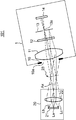
- FIG. 12 is a block diagram showing a configuration of the light receiving unit 1 provided in the optical characteristic measuring apparatus 102 according to the second embodiment. Differences from the optical characteristic measuring apparatus 101 according to the first embodiment shown in FIG. 3 will be described.
- An axis that defines a plane perpendicular to the direction of the optical axis Ax is defined as an x-axis and a y-axis.
- the light receiving unit 1 includes a moving unit 15 that moves the second diaphragm unit 13 and the two-dimensional image sensor 14.
- the moving unit 15 is a position where light (for example, light Lc) constituting another part different from a part of the virtual image VI formed at the position (predetermined position) of the second diaphragm 13 can pass through the opening 13a. Then, the second aperture 13 is moved.
- light for example, light Lc
- the moving unit 15 includes a holding plate 150, a stepping motor M1, and a stepping motor M2.
- the holding plate 150 holds the second diaphragm 13 and the two-dimensional image sensor 14.
- the stepping motor M1 generates power that moves the holding plate 150 along the x-axis direction.
- the stepping motor M2 generates power that moves the holding plate 150 along the y-axis direction.
- the holding plate 150 moves along the y-axis direction.
- FIG. 13 is an explanatory diagram for explaining the path of the light La when the second diaphragm 13 and the two-dimensional image sensor 14 are moved to a position where the light La can pass through the opening 13a.
- FIG. 14 is an explanatory diagram illustrating the path of the light Lc when the second diaphragm 13 and the two-dimensional image sensor 14 are moved to a position where the light Lc can pass through the opening 13a.
- some optical components for example, the objective lens 11 shown in FIG.
- the light La passes through the opening 13a, diffuses, and is diffused to the two-dimensional image sensor 14. It is received by.
- the light Lc passes through the opening 13a, diffuses, and diffuses to the two-dimensional image sensor 14. It is received by.
- the second diaphragm 13 is moved to a position where the light (for example, the light Lc) constituting the other part of the virtual image VI can pass through the opening 13a. Can do.
- the luminance at each position on the exit pupil 23 is measured or the other part of the virtual image VI is constituted.
- the luminance at each position on the exit pupil 23 can be measured with respect to light (for example, light Lc constituting the peripheral portion of the virtual image).
- the moving unit 15 automatically moves the second aperture unit 13 and the two-dimensional image sensor 14 by the stepping motor M1 and the stepping motor M2. Instead of the moving unit 15, the second diaphragm unit 13 and the two-dimensional image sensor 14 may be moved manually.
- the second diaphragm unit 13 alone may be moved without moving the two-dimensional image sensor 14.
- the front focal position of the objective lens 11 is at the position of the opening 10a.
- an image side telecentric optical system is formed (this is the same in the third to fifth embodiments described later). Therefore, the above formula 1 is also established for light constituting the peripheral portion of the image displayed on the image display unit 21 (virtual image VI displayed by the HMD 20). Therefore, even when the luminance of each position on the exit pupil 23 is measured for the light constituting the peripheral portion, the position on the two-dimensional image sensor 14 and the position on the exit pupil 23 can be made to correspond to each other.
- FIG. 15 is a block diagram illustrating a configuration of the light receiving unit 1 provided in the optical characteristic measuring apparatus 103 according to the third embodiment.
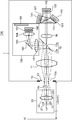
- the optical characteristic measurement apparatus 103 according to the third embodiment is a colorimeter that can measure luminance and chromaticity, and includes an optical finder (observation optical system 18a) that allows a measurer to observe a virtual image VI. Differences from the optical characteristic measuring apparatus 101 according to the first embodiment shown in FIG. 3 will be described.
- the front focal position of the objective lens 11 is at the position of the opening 10a. This is the same as the optical characteristic measuring apparatus 102 according to the second embodiment shown in FIG.
- the second diaphragm unit 13 is an aperture mirror, and includes a mirror unit 13b that is positioned around the opening 13a and reflects light.
- the mirror part 13b reflects light other than the light that has passed through the opening 13a in the light constituting the virtual image VI imaged at the position (predetermined position) of the second diaphragm 13.
- the mirror unit 13 b reflects light constituting the remaining part other than a part of the virtual image VI formed at the position of the second diaphragm unit 13.
- the second diaphragm unit 13 is disposed with an inclination of 45 degrees with respect to the optical axis Ax.
- the light receiving unit 1 of the optical characteristic measuring apparatus 103 does not include the visibility filter 12 and the two-dimensional image sensor 14 illustrated in FIG. 3, and the relay lens 16, the mirror 17 a, the mirror 17 b, the X filter 121, the Y filter 122, and Z A filter 123 and two-dimensional image sensors 141, 142, and 143 are provided.
- a relay lens 16, a mirror 17a, and a mirror 17b are sequentially arranged in the optical path of the light that has passed through the opening 13a.
- the relay lens 16 converts the light that has passed through the opening 13a into parallel light or divergent light and guides it to the mirror 17a.
- the mirror 17a and the mirror 17b are disposed with an inclination of 45 degrees with respect to the optical axis Ax.
- the mirror 17a is a mirror having a reflectance of 33% and a transmittance of 66%.
- the mirror 17b is a mirror having a reflectance of 50% and a transmittance of 50%.
- An X filter 121 and a two-dimensional image sensor 141 are sequentially arranged on the optical path of the light reflected by the mirror 17a. The light reflected by the mirror 17 a passes through the X filter 121 and is received by the two-dimensional image sensor 141.
- Half of the light transmitted through the mirror 17a is reflected and half transmitted through the mirror 17b.
- a Y filter 122 and a two-dimensional image sensor 142 are sequentially arranged in the optical path of the light reflected by the mirror 17b.
- the light reflected by the mirror 17 b passes through the Y filter 122 and is received by the two-dimensional image sensor 142.
- a Z filter 123 and a two-dimensional image sensor 143 are arranged in this order in the optical path of the light transmitted through the mirror 17b.
- the light transmitted through the mirror 17 b passes through the Z filter 123 and is received by the two-dimensional image sensor 143.
- FIG. 16 is an explanatory diagram for explaining the path of the light La in the third embodiment.
- illustration of some optical components for example, the objective lens 11 shown in FIG. 15 located in the path of light is omitted.
- the light La After passing through the opening 13a, the light La is diffused, converted into parallel light by the relay lens 16 (FIG. 15), and guided to the positions of the two-dimensional image sensors 141, 142, and 143.
- Parallel light is received by the two-dimensional image sensors 141, 142, and 143. Since the two-dimensional image sensor 141 receives the parallel light through the X filter 121 (FIG. 15), it outputs a light reception signal indicating X in the XYZ color system. Since the two-dimensional image sensor 142 receives the parallel light through the Y filter 122 (FIG. 15), it outputs a light reception signal indicating Y in the XYZ color system. Since the two-dimensional image sensor 143 receives the parallel light through the Z filter 123 (FIG. 15), it outputs a light reception signal indicating Z in the XYZ color system.
- the position P1 on the exit pupil 23 corresponds to the position p1 on the two-dimensional image sensors 141, 142, 143
- the position P2 on the exit pupil 23 is a position p2 on the two-dimensional image sensors 141, 142, 143
- the position P3 on the exit pupil 23 corresponds to the position p3 on the two-dimensional image sensors 141, 142, and 143. 2 uses the light reception signals (light reception signal indicating X, light reception signal indicating Y, and light reception signal indicating Z) at the position p1 of the two-dimensional image sensors 141, 142, and 143.
- the calculated brightness and chromaticity indicate the brightness and chromaticity at the position P1
- the brightness and chromaticity calculated using the light reception signal at the position p2 indicate the brightness and chromaticity at the position P2, and receive light at the position p3.
- the luminance and chromaticity calculated using the signal indicate the luminance and chromaticity at the position P3.
- the control calculation unit 3 uses the received light signals output from the two-dimensional image sensors 141, 142, 143 on the exit pupil 23.
- the luminance and chromaticity at each position are calculated.
- the output unit 7 outputs the result of this calculation. Therefore, according to the optical characteristic measuring apparatus 103 according to the third embodiment, the luminance and chromaticity at each position on the exit pupil 23 of the HMD 20 can be measured.
- the light receiving unit 1 of the optical characteristic measuring apparatus 103 includes an observation optical system 18a.
- the observation optical system 18a is an optical finder (an example of a finder unit), and in order along the optical path of light reflected by the mirror unit 13b of the second diaphragm unit 13, a lens 181, a plane mirror 182, a diaphragm 183, and a lens. 184, a field stop 185, and an eyepiece 186 are disposed.
- These optical components are ordinary components used in the optical viewfinder, and detailed description thereof is omitted.
- the mirror unit 13 b reflects light other than light passing through the opening 13 a among light constituting the virtual image VI formed at the position of the second diaphragm unit 13. Therefore, the measurer can view the remaining part of the virtual image VI other than the part constituted by the light passing through the opening 13a through the eyepiece 186.
- the measurer sets the position of the objective lens 11 (focusing) in order to form the virtual image VI formed by the light that has passed through the position of the exit pupil 23 on the second diaphragm 13.
- the optical characteristic measurement apparatus 103 uses the light reflected by the mirror unit 13b to display a virtual image VI (not the entire virtual image VI but the remaining part other than a part of the virtual image VI). Since the (observation optical system 18a) is provided, the measurer can easily confirm whether or not the focus of the optical property measuring apparatus 103 is in the virtual image VI.
- the finder unit is not limited to the optical finder, and may be an electronic view finder.
- the fourth embodiment to be described next is an electronic viewfinder.
- the measurer operates the optical characteristic measuring apparatus 103 to move the objective lens 11 in the direction of the optical axis Ax to focus.
- the distance L1 is known from the amount of movement of the objective lens 11 at this time.
- FIG. 17 is a block diagram illustrating a configuration of the light receiving unit 1 provided in the optical characteristic measuring apparatus 104 according to the fourth embodiment.
- the optical characteristic measuring device 104 is a colorimeter that includes an electronic viewfinder and can measure luminance and chromaticity. Differences from the optical characteristic measuring apparatus 103 according to the third embodiment shown in FIG. 15 will be described.
- the observation optical system 18b provided in the light receiving unit 1 of the optical property measuring apparatus 104 is an electronic viewfinder, and in order along the optical path of the light reflected by the mirror unit 13b of the second diaphragm unit 13, A plane mirror 182, a diaphragm 183, a lens 184, a visibility filter 187, and a two-dimensional image sensor 188 are arranged.
- These optical components are ordinary components used in an electronic viewfinder, and detailed description thereof is omitted.
- the observation optical system 18b further includes a display unit 189.
- the two-dimensional image sensor 188 outputs a light reception signal by receiving the light reflected by the mirror unit 13 b of the second diaphragm unit 13.
- This light reception signal is a signal indicating the virtual image VI formed at the position of the second diaphragm 13.
- the mirror unit 13b reflects light other than the light that passes through the opening 13a out of the light that forms the virtual image VI formed at the position of the second diaphragm 13. For this reason, it is not a signal indicating the entire virtual image VI but a signal indicating the remaining part of the virtual image VI other than the part constituted by the light passing through the opening 13a.
- the light reception signal output from the two-dimensional image sensor 188 is sent to the control calculation unit 3 shown in FIG. 2, and the control calculation unit 3 causes the display unit 189 to display an image generated using the light reception signal.
- the image displayed on the display unit 189 is not the entire virtual image VI but the remaining part other than a part of the virtual image VI.
- FIG. 18 is an explanatory diagram illustrating the paths of the light Lb and the light Lc. In this figure, some optical components (for example, the objective lens 11 shown in FIG. 17) located in the light path are not shown.
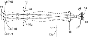
- the image display unit 21 and the two-dimensional image sensor 188 have an optical conjugate relationship.
- the position P6 on the image displayed on the image display unit 21 corresponds to the position p6 on the two-dimensional image sensor 188
- the position P7 on the image displayed on the image display unit 21 is the two-dimensional image sensor 188.
- the control calculation unit 3 (an example of the second calculation unit) illustrated in FIG. 2 uses the light reception signal output from the two-dimensional image sensor 188 to display an image (virtual image displayed by the HMD 20) displayed on the image display unit 21.
- the luminance of each position is calculated.
- the luminance calculated using the light reception signal output from the position p6 indicates the luminance of the position P6
- the luminance calculated using the light reception signal output from the position p7 indicates the luminance of the position P7. Therefore, according to the optical characteristic measuring apparatus 104 according to the fourth embodiment, the luminance distribution at each position is measured in the remaining portion of the image displayed on the image display unit 21 (virtual image VI displayed by the HMD 20). be able to.
- the observation optical system 18b shown in FIG. 17 includes an X filter, a Y filter, and a Z filter instead of the visibility filter 187.
- the observation optical system 18b A two-dimensional image sensor that receives light, a two-dimensional image sensor that receives light that has passed through a Y filter, and a two-dimensional image sensor that receives light that has passed through a Z filter are provided. These two-dimensional image sensors receive light using either the method using the mirror 17a and the mirror 17b described in FIG.
- the light passing through the opening 13a is incident on the three-plate prism 17c.
- the three-plate prism 17c splits this light into three optical paths.
- the first optical path (light passing through the first optical path) passes through the X filter 121 and is received by the two-dimensional image sensor 141.
- the second optical path (light passing through the second optical path) passes through the Y filter 122 and is received by the two-dimensional image sensor 142.
- the third optical path (light passing through the third optical path) passes through the Z filter 123 and is received by the two-dimensional image sensor 143.
- FIG. 19 is an explanatory diagram for explaining the path of the light La.
- some optical components for example, the objective lens 11 shown in FIG. 17 located in the light path are not shown.
- FIG. 19 is the same as FIG. 16 except that a three-plate prism 17c is shown instead of the mirror 17a and the mirror 17b.
- the optical property measurement apparatus 104 according to the fourth embodiment measures the luminance and chromaticity at each position on the exit pupil 23 of the HMD 20 in the same manner as the optical property measurement apparatus 103 according to the third embodiment shown in FIG. can do.
- the optical characteristic measuring apparatus 104 employs a system using a three-plate prism 17c as a system in which the two-dimensional image sensors 141, 142, and 143 receive light.
- the optical characteristic measuring apparatus 104 can also employ the rotary filter 40 (FIG. 20) described in the fifth embodiment. In this case, one two-dimensional image sensor is sufficient.
- the fifth embodiment will be described.
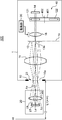
- FIG. 20 is a block diagram illustrating a configuration of the light receiving unit 1 provided in the optical characteristic measurement apparatus 105 according to the fifth embodiment in the measurement mode of the luminance and chromaticity at each position on the exit pupil 23. Differences from the optical characteristic measuring apparatus 101 according to the first embodiment shown in FIG. 3 will be described.
- the front focal position of the objective lens 11 is at the position of the opening 10a. This is the same as the optical characteristic measuring apparatus 102 according to the second embodiment shown in FIG.
- the light receiving unit 1 of the optical characteristic measuring apparatus 105 does not include the visibility filter 12, but includes the slide rail 19, the relay lens 16, the driving unit 30, and the rotary filter 40.
- the second diaphragm 13 is slidable along a slide rail 19 (an example of a first switching unit). By sliding the second diaphragm 13 along the slide rail 19, the position of the second diaphragm 13 can be switched between a predetermined position and a position deviated from the predetermined position.
- the predetermined position is a position at which the virtual image VI formed by the light passing through the position of the exit pupil 23 is formed (the position of the second diaphragm 13 in FIG. 20).
- the position deviated from the predetermined position is a position deviated from the optical path of the light that has passed through the objective lens 11 (the position of the second diaphragm 13 in FIG. 22).
- the measurer may manually slide the second diaphragm 13 to switch the position of the second diaphragm 13, or the second diaphragm 13 may be automatically slid by a motor or the like. The position of the unit 13 may be switched.
- the relay lens 16 and the rotary filter 40 are arranged in order on the optical path of the light that has passed through the opening 13a.
- the relay lens 16 guides the light that has passed through the opening 13 a to the rotary filter 40.
- the relay lens 16 is an example of a relay optical system that is disposed in the optical path between the diaphragm unit (second diaphragm unit 13) and the image sensor (two-dimensional image sensor 14).
- the rotary filter 40 includes an X filter 121, a Y filter 122, a Z filter (not shown), and a rotating plate 401 that holds these filters. As the rotating plate 401 rotates about the shaft 402, an X filter 121, a Y filter 122, and a Z filter (not shown) are sequentially positioned at a position where light relayed by the relay lens 16 passes.
- the driving unit 30 (an example of a second switching unit) drives the relay lens 16 along the direction of the optical axis Ax.
- the relay lens 16 converts the diffused light that has passed through the opening 13 a into parallel light and guides it to the rotary filter 40.
- Light La is shown as light passing through the opening 13a.
- FIG. 21 is an explanatory diagram illustrating the path of the light La. In FIG. 21, illustration of some optical components (for example, the objective lens 11 shown in FIG. 20) located in the path of light is omitted.
- the two-dimensional image sensor 14 When the two-dimensional image sensor 14 receives the parallel light through the X filter 121 (FIG. 20), the two-dimensional image sensor 14 outputs a light reception signal indicating X in the XYZ color system. When the two-dimensional image sensor 14 receives the parallel light through the Y filter 122 (FIG. 20), the two-dimensional image sensor 14 outputs a light reception signal indicating Y in the XYZ color system. When the two-dimensional image sensor 14 receives the parallel light through a Z filter (not shown), the two-dimensional image sensor 14 outputs a light reception signal indicating Z in the XYZ color system.
- the degree indicates the luminance and chromaticity at the position P1
- the luminance and chromaticity calculated using the light reception signal at the position p2 indicate the luminance and chromaticity at the position P2, and are calculated using the light reception signal at the position p3.
- the luminance and chromaticity thus obtained indicate the luminance and chromaticity at the position P3. Therefore, according to the optical characteristic measuring apparatus 105 according to the fifth embodiment, it is possible to measure the luminance and chromaticity at each position on the exit pupil 23 of the HMD 20.
- FIG. 22 is provided in the optical characteristic measurement apparatus 105 according to the fifth embodiment in the mode of measuring the luminance and chromaticity at each position on the image displayed on the image display unit 21 (virtual image VI displayed by the HMD 20). It is a block diagram which shows the structure of the light-receiving part 1 obtained. The difference from FIG. 20 is that the second diaphragm 13 is at a position out of the optical path of the light that has passed through the position of the exit pupil 23, and the relay lens 16 has moved to the rotary filter 40 side.
- the two-dimensional image sensor 14 When the two-dimensional image sensor 14 receives light through the X filter 121 (FIG. 22), the two-dimensional image sensor 14 outputs a light reception signal indicating X in the XYZ color system. When the two-dimensional image sensor 14 receives light through the Y filter 122 (FIG. 22), the two-dimensional image sensor 14 outputs a light reception signal indicating Y in the XYZ color system. When the two-dimensional image sensor 14 receives light through a Z filter (not shown), the two-dimensional image sensor 14 outputs a light reception signal indicating Z in the XYZ color system.
- the position P6 on the image displayed on the image display unit 21 corresponds to the position p6 on the two-dimensional image sensor 14, and the position P7 on the image displayed on the image display unit 21 is the two-dimensional image sensor 14.
- the position P8 on the image displayed on the image display unit 21 corresponding to the upper position p7 corresponds to the position p8 on the two-dimensional image sensor 14. Accordingly, the luminance and color calculated by the control calculation unit 3 shown in FIG. 2 using the light reception signal (light reception signal indicating X, light reception signal indicating Y, and light reception signal indicating Z) at the position p6 of the two-dimensional image sensor.
- the degree indicates the luminance and chromaticity at the position P6 of the image displayed on the image display unit 21, and the luminance and chromaticity calculated using the light reception signal at the position p7 are the values of the image displayed on the image display unit 21.
- the brightness and chromaticity of the position P7 are shown, and the brightness and chromaticity calculated using the received light signal at the position p8 indicate the brightness and chromaticity of the position P8 of the image displayed on the image display unit 21. Therefore, according to the optical characteristic measuring apparatus 105, it is possible to measure the luminance and chromaticity at each position on the image (virtual image VI displayed by the HMD 20) displayed on the image display unit 21.
- the drive unit 30 switches the position of the relay lens 16 between the first position and the second position.
- the first position is the position of the relay lens 16 shown in FIG. 20, and when the position of the second diaphragm 13 is the predetermined position, it forms part of the virtual image VI that has passed through the opening 13a and has spread. This is a position where the relay lens 16 can relay the light (light La) to the two-dimensional image sensor 14.
- the second position is the position of the relay lens 16 shown in FIG. 22.
- the virtual image VI formed at the predetermined position is converted into the relay lens. 16 is a position where an image can be formed on the two-dimensional image sensor 14.
- the control calculation unit 3 (FIG. 2) is an example of a calculation unit, in which the second diaphragm 13 is in the predetermined position and the relay lens 16 is in the first position (the state shown in FIG. 20). ), The optical characteristics (luminance, chromaticity, etc.) of the exit pupil 23 are calculated using the signal output from the two-dimensional image sensor 14, and the second diaphragm 13 is in the above-mentioned position, and With the relay lens 16 in the second position (the state shown in FIG. 22), the optical characteristics (luminance, chromaticity, etc.) of the virtual image VI are calculated using the signal output from the two-dimensional image sensor 14.
- the two-dimensional used for measuring the luminance and chromaticity of each position on the image displayed on the image display unit 21 can be shared.
- the optical characteristic measurement apparatus is configured by light that has passed through the position of the exit pupil in a state where a virtual image that can be seen from the position of the exit pupil of the virtual image display apparatus is displayed by the virtual image display apparatus.
- An imaging optical system that forms the virtual image at a predetermined position, and an aperture that is disposed at the predetermined position and that allows the light that forms part of the virtual image formed at the predetermined position to pass therethrough.
- the optical characteristics of each position on the exit pupil are calculated using a part, an image sensor that passes through the aperture and spreads, and receives the light constituting the part, and a signal output from the image sensor. And an arithmetic unit.
- the imaging optical system forms a virtual image composed of light that has passed through the position of the exit pupil at the position of the diaphragm (predetermined position).
- the light that constitutes a part of the virtual image formed at the position of the diaphragm is parallel light having a predetermined spread at the position of the exit pupil.
- This parallel light is light distributed over the entire exit pupil as viewed from the front of the exit pupil.
- the light constituting the part is spread light (divergent light or parallel light) at the position of the image sensor.
- the present inventor obtains the optical characteristics of each position on the exit pupil of the virtual image display device in a state where the virtual image display device displays a virtual image by using the light reception signal output from the image sensor that has received this light.
- the optical characteristic measuring apparatus according to the present embodiment, the optical characteristic at each position on the exit pupil of the virtual image display apparatus can be measured.
- the apparatus further includes a moving unit that moves the aperture unit to a position where light constituting another part of the virtual image different from the part imaged at the predetermined position can pass through the opening.
- the diaphragm portion can be moved to a position where the light constituting the other part of the virtual image can pass through the opening. For this reason, with respect to the light constituting a part of the virtual image (for example, the central part of the virtual image), the optical characteristic at each position on the exit pupil is measured, or the other part of the virtual image (for example, the peripheral part of the virtual image) is configured. For light, the optical characteristics at each position on the exit pupil can be measured.
- the diaphragm unit includes a mirror unit that is positioned around the opening and reflects light that forms a remaining part other than the part of the virtual image formed at the predetermined position
- the characteristic measurement apparatus further includes a finder unit that displays the remaining portion of the virtual image using the light reflected by the mirror unit.
- This configuration includes the finder unit, so that the measurer can easily confirm whether or not the focus of the optical property measuring device is in a virtual image.
- the finder unit may be either an optical finder or an electronic view finder.
- the diaphragm unit includes a mirror unit that is positioned around the opening and reflects light that forms a remaining part other than the part of the virtual image formed at the predetermined position
- the characteristic measurement device further includes a two-dimensional image sensor that receives light reflected by the mirror unit, and a light reception signal that is output from the two-dimensional image sensor.
- a second computing unit that computes the optical characteristics.
- the optical characteristics at each position on the exit pupil are measured. be able to.
- the relay optical system disposed in the optical path between the diaphragm unit and the image sensor, the position deviated from the optical path of the light passing through the imaging optical system, and the predetermined position, A first switching unit that switches a position of the diaphragm, and light that forms the part of the virtual image that has passed through the opening and spread when the position of the diaphragm is the predetermined position;
- the relay optical system forms the virtual image formed at the predetermined position when the first position at which the image sensor is relayed to the image sensor and the position of the diaphragm portion are at the deviated position.
- a second switching unit that switches a position of the relay optical system to a second position where the image can be formed on the sensor; and the calculation unit includes the diaphragm unit at the predetermined position. And before When the relay optical system is in the first position, the optical characteristic of each position on the exit pupil is calculated using the signal output from the image sensor, and the diaphragm portion is in the off position. And the optical characteristic of each position on the virtual image is calculated using the signal output from the image sensor in a state where the relay optical system is at the second position.
- the image sensor used for measuring the optical characteristics at each position on the exit pupil of the virtual image display device and the optical characteristics at each position on the virtual image displayed by the virtual image display device are used.
- the image sensor can be shared.
- an optical property measuring apparatus can be provided.
Landscapes
- Physics & Mathematics (AREA)
- General Physics & Mathematics (AREA)
- Chemical & Material Sciences (AREA)
- Analytical Chemistry (AREA)
- Optics & Photonics (AREA)
- Testing Of Optical Devices Or Fibers (AREA)
- Photometry And Measurement Of Optical Pulse Characteristics (AREA)
- Spectrometry And Color Measurement (AREA)
Abstract
Description

本実施形態に係る光学特性測定装置は、虚像表示装置の射出瞳の位置から見ることができる虚像が、前記虚像表示装置によって表示された状態で、前記射出瞳の位置を通過した光によって構成される前記虚像を、所定の位置で結像させる結像光学系と、前記所定の位置に配置され、前記所定の位置で結像された前記虚像の一部分を構成する光を通過させる開口を有する絞り部と、前記開口を通過し、広がった、前記一部分を構成する光を受光するイメージセンサと、前記イメージセンサから出力された信号を用いて、前記射出瞳上の各位置の光学特性を演算する演算部と、を備える。
Claims (5)
- 虚像表示装置の射出瞳の位置から見ることができる虚像が、前記虚像表示装置によって表示された状態で、前記射出瞳の位置を通過した光によって構成される前記虚像を、所定の位置で結像させる結像光学系と、
前記所定の位置に配置され、前記所定の位置で結像された前記虚像の一部分を構成する光を通過させる開口を有する絞り部と、
前記開口を通過し、広がった、前記一部分を構成する光を受光するイメージセンサと、
前記イメージセンサから出力された信号を用いて、前記射出瞳上の各位置の光学特性を演算する演算部と、を備える光学特性測定装置。 - 前記所定の位置で結像された前記一部分と異なる前記虚像の他の部分を構成する光が、前記開口を通過できる位置に、前記絞り部を移動させる移動部をさらに備える請求項1に記載の光学特性測定装置。
- 前記絞り部は、前記開口の周囲に位置し、前記所定の位置で結像された前記虚像の前記一部分以外の残りの部分を構成する光を反射させるミラー部を含み、
前記光学特性測定装置は、前記ミラー部で反射された光を用いて、前記虚像の前記残りの部分を表示するファインダ部をさらに備える請求項1又は2に記載の光学特性測定装置。 - 前記絞り部は、前記開口の周囲に位置し、前記所定の位置で結像された前記虚像の前記一部分以外の残りの部分を構成する光を反射させるミラー部を含み、
前記光学特性測定装置は、さらに、
前記ミラー部で反射された光を受光する二次元イメージセンサと、
前記二次元イメージセンサから出力された受光信号を用いて、前記虚像の前記残りの部分において、各位置の光学特性を演算する第2の演算部と、を備える請求項1又は2に記載の光学特性測定装置。 - 前記絞り部と前記イメージセンサとの間の光路に配置されたリレー光学系と、
前記結像光学系を通過した光の光路から外れた位置と、前記所定の位置とに、前記絞り部の位置を切り替える第1の切替部と、
前記絞り部の位置が前記所定の位置のとき、前記開口を通過し、広がった、前記虚像の前記一部分を構成する光を、前記リレー光学系が前記イメージセンサへリレーすることができる第1の位置と、前記絞り部の位置が前記外れた位置のとき、前記所定の位置で結像された前記虚像を、前記リレー光学系によって、前記イメージセンサ上で結像させることができる第2の位置とに、前記リレー光学系の位置を切り替える第2の切替部と、をさらに備え、
前記演算部は、前記絞り部が前記所定の位置にあり、かつ、前記リレー光学系が前記第1の位置にある状態で、前記イメージセンサから出力された信号を用いて、前記射出瞳上の各位置の光学特性を演算し、前記絞り部が前記外れた位置にあり、かつ、前記リレー光学系が前記第2の位置にある状態で、前記イメージセンサから出力された信号を用いて、前記虚像上の各位置の光学特性を演算する請求項1~3のいずれか一項に記載の光学特性測定装置。
Priority Applications (3)
| Application Number | Priority Date | Filing Date | Title |
|---|---|---|---|
| CN201780024344.8A CN109073502B (zh) | 2016-04-19 | 2017-04-14 | 光学特性测定装置 |
| JP2018513162A JP6784293B2 (ja) | 2016-04-19 | 2017-04-14 | 光学特性測定装置 |
| KR1020187025868A KR102056555B1 (ko) | 2016-04-19 | 2017-04-14 | 광학 특성 측정 장치 |
Applications Claiming Priority (2)
| Application Number | Priority Date | Filing Date | Title |
|---|---|---|---|
| JP2016-083494 | 2016-04-19 | ||
| JP2016083494 | 2016-04-19 |
Publications (1)
| Publication Number | Publication Date |
|---|---|
| WO2017183582A1 true WO2017183582A1 (ja) | 2017-10-26 |
Family
ID=60115963
Family Applications (1)
| Application Number | Title | Priority Date | Filing Date |
|---|---|---|---|
| PCT/JP2017/015314 Ceased WO2017183582A1 (ja) | 2016-04-19 | 2017-04-14 | 光学特性測定装置 |
Country Status (4)
| Country | Link |
|---|---|
| JP (1) | JP6784293B2 (ja) |
| KR (1) | KR102056555B1 (ja) |
| CN (1) | CN109073502B (ja) |
| WO (1) | WO2017183582A1 (ja) |
Cited By (5)
| Publication number | Priority date | Publication date | Assignee | Title |
|---|---|---|---|---|
| JP2020065252A (ja) * | 2018-10-17 | 2020-04-23 | 東海光学株式会社 | 画像投影装置、展示装置、評価装置、評価方法及び評価システム |
| WO2022153759A1 (ja) * | 2021-01-14 | 2022-07-21 | ソニーグループ株式会社 | 画像表示装置および画像表示システム |
| CN114993627A (zh) * | 2022-06-17 | 2022-09-02 | 暨南大学 | 一种光学系统虚像视距测量方法 |
| WO2023136072A1 (ja) * | 2022-01-17 | 2023-07-20 | 株式会社ソニー・インタラクティブエンタテインメント | キャリブレーション装置、表示装置、キャリブレーション方法、および画像表示方法 |
| JP2023146533A (ja) * | 2022-03-29 | 2023-10-12 | セイコーエプソン株式会社 | 測定光学装置 |
Families Citing this family (2)
| Publication number | Priority date | Publication date | Assignee | Title |
|---|---|---|---|---|
| WO2020060131A1 (ko) | 2018-09-19 | 2020-03-26 | 주식회사 엘지화학 | LiOH를 포함하는 리튬 이차 전지용 전극, 그의 제조방법, 및 상기 전극을 포함하는 리튬 이차 전지 |
| CN111855152A (zh) * | 2020-07-13 | 2020-10-30 | 成都忆光年文化传播有限公司 | 一种虚拟显示测装方法 |
Citations (4)
| Publication number | Priority date | Publication date | Assignee | Title |
|---|---|---|---|---|
| JPH0291939U (ja) * | 1988-12-28 | 1990-07-20 | ||
| EP0570037A1 (en) * | 1992-05-15 | 1993-11-18 | General Motors Corporation | Head-up display system |
| JP2010522347A (ja) * | 2007-03-22 | 2010-07-01 | イーエーディーエス テスト アンド サービスィズ | オプトエレクトロニクス情報を表示する様々なタイプの装置の動作に関連する複数のパラメータを制御するユニバーサルテストシステム |
| JP2015075381A (ja) * | 2013-10-08 | 2015-04-20 | 株式会社デンソー | 検査装置 |
Family Cites Families (3)
| Publication number | Priority date | Publication date | Assignee | Title |
|---|---|---|---|---|
| CN101266193B (zh) * | 2007-03-13 | 2011-12-28 | 立景光电股份有限公司 | 用于头戴式显示器的影像检测装置及方法 |
| JP2015055689A (ja) | 2013-09-11 | 2015-03-23 | キヤノン株式会社 | オートフォーカスレンズ装置および撮像システム |
| WO2015182571A1 (ja) * | 2014-05-29 | 2015-12-03 | コニカミノルタ株式会社 | 光学特性測定装置および光学特性測定方法 |
-
2017
- 2017-04-14 KR KR1020187025868A patent/KR102056555B1/ko active Active
- 2017-04-14 CN CN201780024344.8A patent/CN109073502B/zh active Active
- 2017-04-14 JP JP2018513162A patent/JP6784293B2/ja active Active
- 2017-04-14 WO PCT/JP2017/015314 patent/WO2017183582A1/ja not_active Ceased
Patent Citations (4)
| Publication number | Priority date | Publication date | Assignee | Title |
|---|---|---|---|---|
| JPH0291939U (ja) * | 1988-12-28 | 1990-07-20 | ||
| EP0570037A1 (en) * | 1992-05-15 | 1993-11-18 | General Motors Corporation | Head-up display system |
| JP2010522347A (ja) * | 2007-03-22 | 2010-07-01 | イーエーディーエス テスト アンド サービスィズ | オプトエレクトロニクス情報を表示する様々なタイプの装置の動作に関連する複数のパラメータを制御するユニバーサルテストシステム |
| JP2015075381A (ja) * | 2013-10-08 | 2015-04-20 | 株式会社デンソー | 検査装置 |
Cited By (10)
| Publication number | Priority date | Publication date | Assignee | Title |
|---|---|---|---|---|
| JP2020065252A (ja) * | 2018-10-17 | 2020-04-23 | 東海光学株式会社 | 画像投影装置、展示装置、評価装置、評価方法及び評価システム |
| JP7396628B2 (ja) | 2018-10-17 | 2023-12-12 | 東海光学株式会社 | 画像投影装置、展示装置、評価装置、評価方法及び評価システム |
| WO2022153759A1 (ja) * | 2021-01-14 | 2022-07-21 | ソニーグループ株式会社 | 画像表示装置および画像表示システム |
| US12175016B2 (en) | 2021-01-14 | 2024-12-24 | Sony Group Corporation | Image display device and image display system |
| WO2023136072A1 (ja) * | 2022-01-17 | 2023-07-20 | 株式会社ソニー・インタラクティブエンタテインメント | キャリブレーション装置、表示装置、キャリブレーション方法、および画像表示方法 |
| JP2023104315A (ja) * | 2022-01-17 | 2023-07-28 | 株式会社ソニー・インタラクティブエンタテインメント | キャリブレーション装置、表示装置、キャリブレーション方法、および画像表示方法 |
| US12494148B2 (en) | 2022-01-17 | 2025-12-09 | Sony Interactive Entertainment Inc. | Calibration device, display device, calibration method, and image display method |
| JP2023146533A (ja) * | 2022-03-29 | 2023-10-12 | セイコーエプソン株式会社 | 測定光学装置 |
| JP7848552B2 (ja) | 2022-03-29 | 2026-04-21 | セイコーエプソン株式会社 | 測定光学装置 |
| CN114993627A (zh) * | 2022-06-17 | 2022-09-02 | 暨南大学 | 一种光学系统虚像视距测量方法 |
Also Published As
| Publication number | Publication date |
|---|---|
| CN109073502A (zh) | 2018-12-21 |
| CN109073502B (zh) | 2021-03-30 |
| JPWO2017183582A1 (ja) | 2019-02-21 |
| KR20180111952A (ko) | 2018-10-11 |
| JP6784293B2 (ja) | 2020-11-11 |
| KR102056555B1 (ko) | 2019-12-16 |
Similar Documents
| Publication | Publication Date | Title |
|---|---|---|
| JP6784293B2 (ja) | 光学特性測定装置 | |
| EP3497423B1 (en) | Apparatus and method for multi configuration near eye display performance characterization | |
| US7136236B2 (en) | Superwide-angle lens optical system, and imaging unit and display unit comprising the same | |
| JP5719650B2 (ja) | 投射型ディスプレイおよび全体像を表示する方法 | |
| CN106461465B (zh) | 光学特性测定装置以及光学特性测定方法 | |
| US11525676B2 (en) | Distance measuring camera | |
| WO2019138970A1 (ja) | 投影距離測定方法及び装置 | |
| JP6798951B2 (ja) | 計測装置および計測装置の作動方法 | |
| JP2009271046A (ja) | 光計測装置及び計測用光学系 | |
| US12072286B2 (en) | Methods and apparatus for a self-aligned digital projection and reflected glare reduction imaging system | |
| US20180284462A1 (en) | Image forming optical system and image reading apparatus including the same | |
| CN109211106B (zh) | 光学测量设备 | |
| JP2009000506A (ja) | 内視鏡 | |
| JP6211261B2 (ja) | 測距装置 | |
| KR19980018382A (ko) | 자동시준방법 및 자동시준장치 | |
| JP4850014B2 (ja) | 分光測光システム及び該システムの照明光源位置の補正方法 | |
| JP2007139622A (ja) | 3次元形状計測装置 | |
| JP3581454B2 (ja) | 角膜厚測定機能を有する角膜内皮撮影装置 | |
| JP2018163103A (ja) | レンズメータ | |
| JP2024107924A (ja) | 撮像装置及び監視システム | |
| WO2022004147A1 (ja) | 光学特性測定光学系および光学特性測定装置 | |
| JP2005284133A (ja) | 合焦情報取得用検出装置及びそれを用いた撮像装置 | |
| Schuster et al. | 72‐1: Requests to Lenses in Measuring Units Evaluating Near‐Eye Displays | |
| JP2005284135A (ja) | 合焦情報取得用検出装置及びそれを用いた撮像装置 | |
| JP2005275063A (ja) | フレア低減ユニットおよびそれを備えた顕微鏡 |
Legal Events
| Date | Code | Title | Description |
|---|---|---|---|
| WWE | Wipo information: entry into national phase |
Ref document number: 2018513162 Country of ref document: JP |
|
| ENP | Entry into the national phase |
Ref document number: 20187025868 Country of ref document: KR Kind code of ref document: A |
|
| WWE | Wipo information: entry into national phase |
Ref document number: 1020187025868 Country of ref document: KR |
|
| NENP | Non-entry into the national phase |
Ref country code: DE |
|
| 121 | Ep: the epo has been informed by wipo that ep was designated in this application |
Ref document number: 17785920 Country of ref document: EP Kind code of ref document: A1 |
|
| 122 | Ep: pct application non-entry in european phase |
Ref document number: 17785920 Country of ref document: EP Kind code of ref document: A1 |