WO2017183254A1 - Aspirateur électrique - Google Patents
Aspirateur électrique Download PDFInfo
- Publication number
- WO2017183254A1 WO2017183254A1 PCT/JP2017/003811 JP2017003811W WO2017183254A1 WO 2017183254 A1 WO2017183254 A1 WO 2017183254A1 JP 2017003811 W JP2017003811 W JP 2017003811W WO 2017183254 A1 WO2017183254 A1 WO 2017183254A1
- Authority
- WO
- WIPO (PCT)
- Prior art keywords
- suction port
- vacuum cleaner
- electric
- suction
- port body
- Prior art date
Links
Images


Classifications
-
- A—HUMAN NECESSITIES
- A47—FURNITURE; DOMESTIC ARTICLES OR APPLIANCES; COFFEE MILLS; SPICE MILLS; SUCTION CLEANERS IN GENERAL
- A47L—DOMESTIC WASHING OR CLEANING; SUCTION CLEANERS IN GENERAL
- A47L9/00—Details or accessories of suction cleaners, e.g. mechanical means for controlling the suction or for effecting pulsating action; Storing devices specially adapted to suction cleaners or parts thereof; Carrying-vehicles specially adapted for suction cleaners
- A47L9/02—Nozzles
- A47L9/04—Nozzles with driven brushes or agitators
Definitions
- This invention relates to a vacuum cleaner.
- an electric vacuum cleaner in which an electric blower and a vacuum cleaner main body including a dust collecting chamber are connected to a suction port body having a rotary brush and a wheel and driving an electric motor.
- a suction port body having a rotary brush and a wheel and driving an electric motor.
- JP 2000-37325 A Japanese Patent Laid-Open No. 7-8417
- the present invention has been made in view of such circumstances, and provides a vacuum cleaner that can be reduced in size and weight by cooling an electric motor mounted on a suction port body.
- the present invention relates to a vacuum cleaner body including an electric blower for sucking dust and a dust collecting chamber for storing sucked dust, a suction port body having a suction port for sucking dust, and a suction body for the vacuum cleaner.
- a suction pipe that connects the suction port and the connection pipe, a rotary brush provided in the suction port, and a self-running travel of the suction mouth body.
- a running roller, first and second electric motors that respectively drive the rotating brush and the self-running roller, and an air passage connected to the suction passage from an opening for sucking outside air formed in a part of the suction port body And providing at least one of the first electric motor and the second electric motor to the outside air passing through the air passage to cool the electric vacuum cleaner.
- the outside air is sucked from the opening for sucking the outside air formed in a part of the suction port body and is cooled by being brought into contact with at least one of the first and second electric motors, it is mounted on the suction port body. This makes it possible to reduce the size and weight of the motor.
- FIG. 1st Embodiment of the vacuum cleaner of this invention It is an external appearance perspective view which shows 1st Embodiment of the vacuum cleaner of this invention. It is internal structure explanatory drawing of the vacuum cleaner shown in FIG. It is a perspective view which shows the suction inlet body of the vacuum cleaner of FIG. It is a bottom view which shows the suction inlet body of the vacuum cleaner of FIG. It is a longitudinal cross-sectional view which shows the suction inlet body of the vacuum cleaner of FIG. It is a perspective view which shows the drive roller unit in the suction inlet of the vacuum cleaner of FIG. It is a disassembled perspective view of the suction inlet body of the vacuum cleaner of FIG.
- FIG. 10 is a view corresponding to FIG. 9 showing a second embodiment of the electric vacuum cleaner of the present invention.
- FIG. 12 is a diagram corresponding to FIG. 10 of the second embodiment shown in FIG. 11. It is FIG. 11 corresponding view which shows 3rd Embodiment of the vacuum cleaner of this invention.
- FIG. 1 is an external perspective view showing a first embodiment of the electric vacuum cleaner of the present invention
- FIG. 2 is an explanatory diagram of the internal configuration of the electric vacuum cleaner shown in FIG.
- the vacuum cleaner 1 includes a cleaner body 2, a suction port body 40, and a connection pipe (extension pipe) 4 that hermetically connects the cleaner body 2 to the suction port body 40. .
- the vacuum cleaner body 2 includes a handle 5 held by the operator, an operation unit 6 provided on the handle 5 and having a start / stop switch, and a connection unit 7 that receives the base end of the connection pipe 4 and is detachably connected. Prepare.
- the suction port body 40 includes a connection shaft portion 42 x that can swing the connection pipe portion 42 with respect to the suction port body 40 in an angle range of 90 degrees.
- the cleaner body 2 includes a dust collection chamber 11 that is detachably installed, a dust collection filter 12 that is provided on the downstream side of the dust collection chamber 11, an electric blower 13, and a dust collection filter 12. And an air flow path 14 that connects the electric blower 13, an exhaust flow path 37 provided downstream of the electric blower 13, and a flow path 39 that connects the connection portion 7 and the dust collection chamber 11.
- a well-known cyclone type can be suitably used for the dust collection chamber 11.
- the battery 17 mentioned later is loaded in the cleaner main body 2 so that replacement
- FIG. 1 and FIG. 2 show a state where the vacuum cleaner 1 is standing on the floor surface F.
- the angle formed between the suction port body 40 and the connecting pipe 4 is slightly smaller than 90 degrees, and the center of gravity of the cleaner body 2 is in a state of equilibrium so that the vacuum cleaner 1 can stand on the floor surface F.
- FIG. 3 is a perspective view showing a suction port body of the vacuum cleaner of FIG. 1
- FIG. 4 is a bottom view showing the suction port body of the vacuum cleaner of FIG. 1
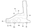
- FIG. 5 is a view of the vacuum cleaner of FIG. It is left sectional drawing which shows a suction inlet.
- 6 is a perspective view showing a driving roller unit in the suction port body of the vacuum cleaner of FIG. 1
- FIG. 7 is an exploded view of the suction port body of the vacuum cleaner of FIG.
- FIG. 8 is explanatory drawing which shows the rocking
- the suction port body 40 is swingable about a left and right axis around the suction port body 41 having a bottom surface provided with a suction port 41a 1 extending in the left-right direction (arrow A1 direction) and the rear portion of the suction port body 41.
- a drive roller unit 45 provided on the bottom surface side of the suction inlet body 41, a posture detection switch 46, and a lifting detection switch 47.
- Suction port body 40 is provided with a lower case 41a having a suction port 41a 1, and an upper case 41b, the front case 41c, a bumper 41d, and cylindrical receiving portions 41e, and a rear case 41f.
- Lower case 41a is a suction port 41a and the first space above the opening shape 1 of the rotary brush 43 upwardly rotatably accommodated, lifting detection switch 47 and the rotary brush motor 44 is disposed behind the first space
- a second space having an upper opening shape for storing the space, a third space having a lower opening shape for storing the driving roller unit 45 disposed behind the second space, and a rear space of the third space or the second space.
- a hole 41a 2 is formed in the second space. The hole 41a 2 exposes a part of the lifting detection switch 47 to the outside downward.
- the upper case 41b is a component that covers the second space and the third space of the lower case 41a.
- the rear end portion restricts the rotation of the connection pipe portion 42 that is swung to a substantially vertical state in the twisting direction.
- a restricting piece 41b 1 is provided.
- the front case 41c is a part that covers the first space of the lower case 41a, and is a part to which the bumper 41d is attached.
- reference numeral 41 cx denotes a stopper piece that is detachably attached between the left and right rear end portions of the front case and the left and right front end portions of the upper case 41 b, and the lower case is obtained by removing each stopper piece 41 cx.
- the upper case 41b and the front case 41c can be detached from 41a.
- the lifting detection switch 47 includes a swing lever portion having a wheel, a switch body that supports the swing lever portion so as to be swingable, and a torsion coil spring that biases the swing lever portion downward, and includes a lower case.
- 41a switch body is connected to the housing circuit boards 48, the wheels of the swing lever portion is biased to expose the holes 41a 2 to the outside downward.
- the lifting detection switch 47 switches the motor to drive when the suction port body 40 is on the floor surface F, and stops driving the motor when the suction port body 40 is lifted from the floor surface F.
- the “motor” referred to here includes the rotating brush motor 44 and a driving roller motor 45b described later provided in the driving roller unit 45.
- the rotating brush 43 has a grooved pulley on one end thereof, and a grooved pulley is fixed to the output shaft of the rotating brush motor 44, and a grooved belt is stretched between these grooved pulleys. As a result, the rotational force of the rotary brush motor 44 is transmitted to the rotary brush 43.
- the rear case 41f has an arcuate portion that fits with the peripheral edge of the third space of the lower case 41a so as to surround the drive roller unit 45 from the rear to the left and right, and a lower portion that is connected to the arcuate portion.
- the case 41a has a fan-shaped portion that fits with the peripheral portion of the fourth space, and a bottom opening (bottom surface) for the pair of left and right rear rollers 49 to be rotatably mounted around the left-right axis. Mounting recesses are provided.
- the cylindrical member 41g is rear case 41f having a convex curved surface portion 41g 1 on the lower end so as to protrude from the circular hole to the outside downward It is provided above.
- the left and right positions and lower case 41a of the arc-shaped part of the rear case 41f on the left and right position of the third space, left and right to be described later of the driving roller unit 45 the shaft portion 45d 11 a rotatably supported to a semi-circular Ribs 41h are provided.
- the receiving portion 41e is a component that holds the connection pipe portion 42 so as to be swingable about the axis in the left-right direction, and includes a lower member 41e 1 and an upper member 41e 2 that can be divided into two parts.
- the lower member 41e 1 has a circular vent hole portion 41e 11 at the front end and an attachment portion 41e 12 for attaching the posture detection switch 46 to the left end portion of the semi-cylindrical portion.
- the upper member 41e 2 is formed with a notch 41e 21 at the rear end so that the connection pipe portion 42 can swing to a substantially vertical state.
- Circular outer periphery of the lower member 41e 1 and the upper member 41e 2 and vents receiving portion 41e of the assembled unit 41e 11 is fitted into the semi-circular rib 41e 13 respectively provided on the lower case 41a and upper case 41b It is attached so as to be rotatable around the axial center in the front-rear direction.
- connection pipe portion 42 includes a cylindrical main body portion 42a having a ventilation path, and an upper cover portion 42b attached to the main body portion 42a, and the receiving portion 41e of the suction inlet main body 41 and the axis center in the left-right direction. And a connecting shaft portion 42x that is swingably connected to the base end side (root side).
- connection shaft portion 42x the surface on the swinging direction side (arrow B1 direction side) of the connection pipe portion 42, that is, a part of the outer surface of the main body portion 42a and a part of the outer surface of the upper cover portion 42b are convex curved surfaces. It is connected to the receiving portion 41e of the suction port body 41 so as to be swingable around the axis in the left-right direction (in the direction of arrow B1) (see FIG. 2).
- Lower cover portion 42a has a protruding switch contact portion 42a 1 on the left side surface of the proximal end portion.
- the switch abutting portion 42a 1 abuts on the lever 46a of the attitude detection switch 46 attached to the receiving portion 41e when the connecting shaft portion 42x swings to switch the motor from driving to stopping.
- the “motor” referred to here includes the rotating brush motor 44 and a driving roller motor, which will be described later, provided in the driving roller unit 45.
- the upper cover portion 42b has an inclined surface adjacent to the convex curved surface and a constricted portion 42b 1 between the inclined surface and the convex curved surface, and the connection pipe portion 42 is in an inclined state (FIG. 8A). )) To the vertical state (FIG. 8B), the constricted part 42b 1 is stopped against the inner part of the notch 41e 21 of the receiving part 41e, and further swinging is restricted.
- the “vertical state” of the connection pipe portion 42 means a state that is substantially perpendicular to the floor surface F.
- FIG. 10 is a front view of the drive roller of FIG. 9, and FIG. 11 is a sectional view of the drive roller of FIG.
- Drive roller unit 45 includes a drive roller 45a, the drive roller motor 45b, the rotational force transmission mechanism having a grooved belt 45 c 1 and will have a casing 45d for accommodating them, and the suction port body 40 driving roller unit 45 Is attached to the suction inlet main body 41 so as to be urged toward the floor surface F by an urging member (not shown) provided therebetween.
- Casing 45d includes a first casing 45d 1, comprising a second casing 45d 2 assembled to the first upper casing 45d 1, and a third casing 45d 3 assembled to the first lower casing 45d 1.
- the first casing 45d 1 has a shaft portion 45d 11 on the left and right side surfaces.
- the second casing 45d 2 has a short cylindrical recess 45d 21 into which the lower end portion of the coil spring as the biasing member is fitted at the left and right positions on the upper surface.
- the third casing 45d 3 has an opening 45d 31 for projecting the driving roller 45a to the floor surface F side.
- Drive roller motor 45b is accommodated in the space between the first casing 45d 1 and second casing 45d 2, the driving roller 45a is in the horizontal direction in the space between the first casing 45d 1 and the third casing 45d 3 It is stored so that it can rotate around its axis.
- the driving roller 45a includes a rotating member 45a 1 connected to the rotational force transmission mechanism, a cylindrical roller member 45a 2 provided on the outer peripheral side of the rotating member, and between the rotating member 45a 1 and the roller member 45a 2. And a roller fixing member 45a 3 provided on the surface.
- the cylindrical roller fixing member 45a 3 includes inner flange portions 45a 31 provided at both end portions in the axial direction and a pair of annular convex portions 45a 32 provided on the outer peripheral surface at predetermined intervals in the axial direction. It has a halved body 45a 33 that can be divided into two.
- the cylindrical roller member 45a 2 is fitted between the pair of annular convex portions 45a 32 of the roller fixing member 45a 3 .
- the rotating member 45a 1 includes a main body 45a 11 having a pair of outer flange portions 45a 111 provided on the outer peripheral surface at predetermined intervals in the axial direction, and pins and bearings 45a at both axial ends of the main body 45a 11 . And a support block 45a 13 which is rotatably mounted via 12 .
- grooved pulleys 45a 112 constituting the rotational force transmission mechanism are integrally molded. Further, the inner flange portions 45a 31 of the pair of halves 45a 33 fitted between the pair of outer flange portions 45a 111 are fitted inside the pair of outer flange portions 45a 111 at the outer peripheral portion of the main body portion 45a 11. A recessed circumferential groove 45a 113 is formed.
- one or more cuts are formed in a part of the inner flange portion 45a 31 of the half body 45a 33 , and one or more protrusions are provided in a part of the concave circumferential groove 45a 113 , When the protrusion engages with the notch, the rotating member 45a 1 and the roller fixing member 45a 3 are mechanically coupled and rotate integrally.
- Examples of the material of the rotating member 45a 1 include resins such as POM (polyacetal), PET (polyethylene terephthalate), and PTFE (tetrafluoroethylene). In this embodiment, POM is used.
- the material of the roller fixing member 45a 3 is a resin having a lower organic solvent resistance than the material of the rotating member 45a 1 , for example, ABS (styrene / butadiene / acrylonitrile copolymer), AS (styrene / acrylonitrile copolymer). ), PS (polystyrene), and the like, and ABS is used in this embodiment.
- roller member 45a 2 examples include rubbers such as silicone rubber, fluorine rubber, and chlorosulfonated polyethylene rubber. In the present embodiment, silicone rubber is used.
- the roller member 45a 2 may be bonded to the roller fixing member 45a 3 using an adhesive, or may be directly covered without using an adhesive. In the case of using an adhesive, any adhesive may be used as long as it can bond the roller member 45a 2 and the roller fixing member 45a 3 , for example, an acrylic resin, vinyl chloride resin, chloroprene rubber, nitrile rubber, or the like. Is mentioned.
- the rotational force transmission mechanism includes a grooved pulley 45b 1 fixed to the output shaft of the drive roller motor 45b, a grooved pulley 45a 112 of the drive roller 45a, and a groove between these grooved pulleys 45b 1 and 45a 112. And a grooved belt 45c 1 (see FIG. 7).
- the axis of the drive roller 45 a is the first axis P 1
- the axis of the connection shaft part 42 x of the connection pipe part 42 is the second axis P 2
- the axis of the rotary brush 43 is the axis.
- the third axis P 3 , the axis of the pair of rear rollers 49 as the fourth axis P 4 , and the axis of the drive roller motor 45 b as the fifth axis P 5 will be described.
- the drive roller 45 a is disposed at an intermediate position in the left-right direction (arrow A ⁇ b> 1 direction) in the suction port body 41. Further, as shown in FIG. 5, the first axis P 1 is disposed between the second axis P 2 and the suction port 41a 1 or the third axis P 3 . By disposing one drive roller 45a at such a position, it is possible to improve the turning operability of the suction port body 40 while suppressing the load applied to the rotary brush motor 44.
- the fourth axis P 4 is disposed at a rear position with respect to the second axis P 2 .
- the pair of left and right rear rollers 49 it is effective to make the vacuum cleaner 100 stand up substantially vertically by supporting the driving roller 45a and the pair of left and right rear rollers 49 at three points. (Refer to FIG. 2) Further, the rear roller 49 can suppress the rear portion of the suction port body 40 from coming into contact with the flooring floor F and being damaged.
- the shaft portion 45d 11 of the drive roller unit 45 is disposed on substantially the same axis as the fifth axis P5 of the rear of the drive roller motor 45b than the first axis P 1 of the driving roller 45a, with and energizing member is disposed forwardly of the shaft portion 45d 11. Therefore, it is possible to drive roller unit 45 to the shaft portion 45d 11 as a fulcrum becomes swingable in a vertical direction (arrow C1), the load adjustment of the vertical movement of the drive roller 45a by the biasing member.
- arrow C1 the load adjustment of the vertical movement of the drive roller 45a by the biasing member.
- the coil spring as a biasing member may be provided two, but the driving roller unit 45 are two recesses 45d 21 has described the case provided, the number of recesses 45d 21 3 Further, the number of coil springs actually provided may be changed according to the load to be applied to the drive roller 45a.
- FIG. 9 and FIG. 10 are a plan view and a side view for explaining the internal structure of the suction port body 40 equivalently.
- the cooling mechanism of the suction inlet 40 will be described with reference to FIGS. 9 and 10.
- the suction port body 40 has a housing formed of the lower case 41a, the upper case 41b, the front case 41c, the rear case 41f, and the like, as shown in FIGS. 9 and 10.
- the top plate 24, the bottom plate 25, and the side plate 26 provided along the outer periphery between them are equivalently provided.
- the suction port body 40 includes a rotary brush 43 provided at the suction port 41a 1 and rotatably supported at both ends of a rotary shaft, and a rotary brush motor (hereinafter referred to as a first electric motor) installed on the bottom plate 25 and driving the rotary brush 43. 44), a grooved pulley 20 provided on the rotating shaft of the rotating brush 43, a grooved pulley 22 provided on the output shaft of the first electric motor 44, and a grooved belt for connecting the grooved pulleys 20 and 22. 23.
- a rotary brush motor hereinafter referred to as a first electric motor
- a pair of rear rollers 49 that movably support the suction port body 40 are provided behind the bottom plate 25, and a part of the bottom plate 25 is exposed downward from the bottom plate 25 at the center of the bottom plate 25 (FIG. 2).
- a grooved pulley 45a 112 provided at one end (left end) of the rotating shaft of the self-running roller 45a, a grooved pulley 45b 1 provided at the output shaft of the second electric motor 45b, and grooved pulleys 45b 1 and 45a 112 are provided.
- a grooved belt 45c 1 to be connected is provided.
- the suction port 41a 1 and the connection pipe portion 42 are connected by the suction flow channel 16, and the suction flow channel 16 is a self-propelled roller.
- 45a, the second electric motor 45b, and the top plate 24 are provided so as to pass in a straight line when viewed from above.
- the side plate 26 includes a first opening 32 and a second opening 33 for sucking outside air
- the suction channel 16 includes a first suction port 34 and a second suction port 35. Accordingly, cooling air passages A and B indicated by arrows are formed between the first opening 32 and the first suction port 34 and between the second opening 33 and the second suction port 34, respectively.
- the cooling air passages A and B are used to cool the first electric motor 44 and the second electric motor 45b, respectively.
- the first opening 32 and the second opening 33 preferably each include a dustproof filter.
- the self-propelled roller 45a is driven so that the suction port body 40 is self-propelled on the floor surface F and the operator follows the suction port body 40 while holding the vacuum cleaner body 2, thereby rotating the rotary brush 43. Dust on the floor surface is collected and sucked into the dust collecting chamber 11 through the suction channel 16, the connecting pipe 4 and the channel 39 together with air from the suction port 41 a 1 as shown in FIG. 2.
- the air containing dust sucked into the dust collection chamber 11 is filtered by the dust collection filter 12, and only clean air is discharged from the electric blower 13 through the flow path 14 to the outside through the exhaust flow path 37.
- the dust collected by the dust collection filter 12 falls by gravity and is collected at the bottom of the dust collection chamber 11.
- the operator removes the dust collection chamber 11 from the cleaner body 2 and discards the accumulated dust.
- the fine dust that does not fall from the dust collection filter 12 and adheres to the dust collection filter 12 is removed from the dust collection filter 12 by washing or the like.
- the operator When finishing the cleaning work, the operator operates the stop switch of the operation unit 6. Thereby, the supply of electric power from the battery 17 to the electric blower 13, the first and second electric motors 44, 45b is stopped, the self-running operation in the suction port body 40, the rotation operation of the rotary brush 43, and the suction of the suction port 41a 1 Operation stops. Then, an operator returns the vacuum cleaner 1 to the attitude
- the lifting detection switch 47 that has been pushed into the suction port body 41 protrudes to the outside. If it will be in this state, the drive of the 1st and 2nd electric motors 44 and 45b will stop, and the rotation of the rotating brush 43 and the running roller 45a will stop.
- connection pipe portion 42 of the suction port body 40 is in a vertical state in which it swings upward by a predetermined angle or more as shown in FIG. 8B.
- the switch contact portion 42a 1 (FIG. 7) provided on the connection shaft portion 42x of the connection pipe portion 42 pushes down the lever 46a of the posture detection switch 46, whereby the posture detection switch 46 is moved to the first and second positions. 2 Stop driving the electric motors 44 and 45b.
- the first motor 44 and the second motor 45b are cooled as follows. That is, when the operation of the electric vacuum cleaner 1 is started as described above and the electric blower 13 is driven, the air containing dust from the suction port 41a 1 is connected to the connecting pipe portion via the suction passage 16 as shown in FIG. 42 is aspirated.
- the outside air flows through the air passage B extending from the second opening 33 of the side plate 26 shown in FIG. 9 to the second suction port 35 of the suction passage 16, and the second electric motor 45b.
- the second electric motor 45b is cooled. Therefore, the first motor 44 and the second motor 45b are reduced in size and weight without changing the output capacity.
- FIG. 11 is a diagram corresponding to FIG. 9 showing the second embodiment of the electric vacuum cleaner 1
- FIG. 12 is a diagram corresponding to FIG. 12 showing the second embodiment.
- the suction flow path 16 of the suction port body 40 of the first embodiment, the connecting pipe portion 42 has been replaced with the suction channel C connected to along the bottom plate 25 from the suction port 41a 1, the first The suction port 34 is replaced with a first suction port 34a, and the second suction port 35 is replaced with a second suction port 35a.
- Other configurations and operations are the same as those of the first embodiment. In this embodiment, the same effect as in the first embodiment can be obtained.
- the suction flow path C is provided low along the bottom plate 25 between the self-running roller 45a and the second electric motor 45b and the side plate 26.
- the height of the top plate 24 of the mouth body 40 can be reduced, and the suction mouth body 40 itself can be reduced in size.
- FIG. 13 is a view corresponding to FIG. 9 showing a third embodiment of the vacuum cleaner 1.
- the suction flow path 16 of the suction port body 40 of the first embodiment, along the bottom plate 25 was replaced with the connected suction channel D to the connecting pipe portion 42 from the suction port 41a 1, the first The suction port 34 and the second suction port 35 are merged to form the third suction port 38, and the ventilation path A and the ventilation path B are merged to form the ventilation path E.
- the second opening 33 (FIG. 3) of the first embodiment is closed, the self-propelled roller 45a and the second electric motor 45b are arranged in opposite directions, and the outside air flowing in from the first opening 32 is used in common.
- the first motor 44 and the second motor 45b are cooled at the same time.
Landscapes
- Engineering & Computer Science (AREA)
- Mechanical Engineering (AREA)
- Nozzles For Electric Vacuum Cleaners (AREA)
- Cleaning In General (AREA)
Abstract
La présente invention a pour but d'obtenir une réduction de la taille et du poids d'un corps d'orifice d'aspiration d'un aspirateur électrique. L'invention concerne un aspirateur électrique qui est pourvu : d'un corps principal d'aspirateur pour loger intérieurement une soufflante électrique pour aspirer la poussière et une chambre collectrice de poussière pour stocker la poussière aspirée ; d'un corps d'orifice d'aspiration ayant un orifice d'aspiration pour aspirer la poussière ; d'un tuyau de raccord pour relier le corps principal d'aspirateur au corps d'orifice d'aspiration, l'aspirateur électrique étant caractérisé en ce que le corps d'orifice d'aspiration est pourvu d'un passage d'écoulement d'aspiration pour relier l'orifice d'aspiration et le tuyau de raccord, d'une brosse rotative disposée sur l'orifice d'aspiration, d'un rouleau automoteur pour permettre au corps d'orifice d'aspiration de se déplacer, de premier et second moteurs électriques pour entraîner respectivement la brosse rotative et le rouleau automoteur, et d'un passage de ventilation relié au passage d'écoulement d'aspiration à partir d'une ouverture pour aspirer l'air extérieur, l'ouverture étant formée dans une partie du corps d'orifice d'aspiration, et au moins un des premier et second moteurs électriques étant amené en contact et refroidi par l'air extérieur passant à travers le passage de ventilation.
Priority Applications (2)
| Application Number | Priority Date | Filing Date | Title |
|---|---|---|---|
| JP2018512788A JPWO2017183254A1 (ja) | 2016-04-18 | 2017-02-02 | 電気掃除機 |
| CN201780014219.9A CN109068911A (zh) | 2016-04-18 | 2017-02-02 | 电动吸尘器 |
Applications Claiming Priority (2)
| Application Number | Priority Date | Filing Date | Title |
|---|---|---|---|
| JP2016-083032 | 2016-04-18 | ||
| JP2016083032 | 2016-04-18 |
Publications (1)
| Publication Number | Publication Date |
|---|---|
| WO2017183254A1 true WO2017183254A1 (fr) | 2017-10-26 |
Family
ID=60116680
Family Applications (1)
| Application Number | Title | Priority Date | Filing Date |
|---|---|---|---|
| PCT/JP2017/003811 WO2017183254A1 (fr) | 2016-04-18 | 2017-02-02 | Aspirateur électrique |
Country Status (3)
| Country | Link |
|---|---|
| JP (1) | JPWO2017183254A1 (fr) |
| CN (1) | CN109068911A (fr) |
| WO (1) | WO2017183254A1 (fr) |
Families Citing this family (1)
| Publication number | Priority date | Publication date | Assignee | Title |
|---|---|---|---|---|
| JP7097616B2 (ja) * | 2019-07-31 | 2022-07-08 | アイリスオーヤマ株式会社 | 電気掃除機の吸込口体、及び電気掃除機 |
Citations (4)
| Publication number | Priority date | Publication date | Assignee | Title |
|---|---|---|---|---|
| JPH02144030A (ja) * | 1988-11-28 | 1990-06-01 | Tokyo Electric Co Ltd | 電気掃除機の吸込口体 |
| JPH0630866A (ja) * | 1992-07-17 | 1994-02-08 | Sanyo Electric Co Ltd | 床用吸込具 |
| JP2012000458A (ja) * | 2010-06-15 | 2012-01-05 | Panasonic Corp Of North America | 内部ツインモーター駆動システムを備えたアジテーター |
| JP2012152102A (ja) * | 2012-04-27 | 2012-08-09 | Hitachi Appliances Inc | 電動機 |
Family Cites Families (1)
| Publication number | Priority date | Publication date | Assignee | Title |
|---|---|---|---|---|
| GB2499213B (en) * | 2012-02-08 | 2016-10-19 | Dyson Technology Ltd | A cleaner-head for a vacuum cleaner |
-
2017
- 2017-02-02 WO PCT/JP2017/003811 patent/WO2017183254A1/fr active Application Filing
- 2017-02-02 JP JP2018512788A patent/JPWO2017183254A1/ja active Pending
- 2017-02-02 CN CN201780014219.9A patent/CN109068911A/zh active Pending
Patent Citations (4)
| Publication number | Priority date | Publication date | Assignee | Title |
|---|---|---|---|---|
| JPH02144030A (ja) * | 1988-11-28 | 1990-06-01 | Tokyo Electric Co Ltd | 電気掃除機の吸込口体 |
| JPH0630866A (ja) * | 1992-07-17 | 1994-02-08 | Sanyo Electric Co Ltd | 床用吸込具 |
| JP2012000458A (ja) * | 2010-06-15 | 2012-01-05 | Panasonic Corp Of North America | 内部ツインモーター駆動システムを備えたアジテーター |
| JP2012152102A (ja) * | 2012-04-27 | 2012-08-09 | Hitachi Appliances Inc | 電動機 |
Also Published As
| Publication number | Publication date |
|---|---|
| JPWO2017183254A1 (ja) | 2019-02-21 |
| CN109068911A (zh) | 2018-12-21 |
Similar Documents
| Publication | Publication Date | Title |
|---|---|---|
| JP6114367B2 (ja) | モップモジュール及びそれを備えるロボット掃除機 | |
| CN107041714B (zh) | 机器人吸尘器 | |
| KR101622713B1 (ko) | 로봇 청소기 | |
| WO2006080383A1 (fr) | Nettoyeur electrique et corps de bouche d’aspiration | |
| KR20160065683A (ko) | 로봇 청소기 | |
| US8453294B2 (en) | Upright vacuum cleaner having path switching apparatus | |
| US9060662B2 (en) | Upright type vacuum cleaner | |
| JP2009189795A (ja) | 掃除装置 | |
| KR20190133612A (ko) | 로봇 집진기 | |
| US9622633B2 (en) | Robot cleaner | |
| WO2020121847A1 (fr) | Dispositif de nettoyage | |
| JP6121656B2 (ja) | 電気掃除機およびその吸込口体 | |
| WO2017183254A1 (fr) | Aspirateur électrique | |
| JP7224967B2 (ja) | アップライト集じん機 | |
| JP2013252255A (ja) | 電気掃除機およびその吸込口体 | |
| US20060130267A1 (en) | Electric cleaner | |
| JP5380160B2 (ja) | 吸込口体および電気掃除機 | |
| JP2017192410A (ja) | 電気掃除機の吸込具及びこれを備える電気掃除機 | |
| WO2017183251A1 (fr) | Ensemble d'aspiration destiné à un aspirateur électrique | |
| WO2017183250A1 (fr) | Ensemble entrée d'aspiration pour aspirateur électrique | |
| JP6572080B2 (ja) | 電気掃除機およびその吸込口体 | |
| JP6519291B2 (ja) | 電気掃除機 | |
| JP3594178B2 (ja) | 電気掃除機およびその吸込口体 | |
| US20230136162A1 (en) | Robotic dust collector | |
| KR102367199B1 (ko) | 로봇 청소기 |
Legal Events
| Date | Code | Title | Description |
|---|---|---|---|
| ENP | Entry into the national phase |
Ref document number: 2018512788 Country of ref document: JP Kind code of ref document: A |
|
| NENP | Non-entry into the national phase |
Ref country code: DE |
|
| 121 | Ep: the epo has been informed by wipo that ep was designated in this application |
Ref document number: 17785599 Country of ref document: EP Kind code of ref document: A1 |
|
| 122 | Ep: pct application non-entry in european phase |
Ref document number: 17785599 Country of ref document: EP Kind code of ref document: A1 |