WO2017183112A1 - Blood pressure meter - Google Patents
Blood pressure meter Download PDFInfo
- Publication number
- WO2017183112A1 WO2017183112A1 PCT/JP2016/062410 JP2016062410W WO2017183112A1 WO 2017183112 A1 WO2017183112 A1 WO 2017183112A1 JP 2016062410 W JP2016062410 W JP 2016062410W WO 2017183112 A1 WO2017183112 A1 WO 2017183112A1
- Authority
- WO
- WIPO (PCT)
- Prior art keywords
- pressure
- valve
- cuff
- pump
- blood pressure
- Prior art date
Links
- 230000036772 blood pressure Effects 0.000 title claims abstract description 33
- 238000009530 blood pressure measurement Methods 0.000 claims abstract description 45
- 238000001514 detection method Methods 0.000 claims abstract description 22
- 210000001367 artery Anatomy 0.000 claims abstract description 7
- 238000005259 measurement Methods 0.000 claims description 24
- 230000000149 penetrating effect Effects 0.000 claims description 2
- 238000000034 method Methods 0.000 description 36
- 230000008569 process Effects 0.000 description 25
- 230000008859 change Effects 0.000 description 14
- 230000005540 biological transmission Effects 0.000 description 12
- 238000010586 diagram Methods 0.000 description 11
- 230000004913 activation Effects 0.000 description 4
- 230000004872 arterial blood pressure Effects 0.000 description 4
- 239000012530 fluid Substances 0.000 description 4
- 230000008602 contraction Effects 0.000 description 3
- 239000000463 material Substances 0.000 description 3
- 230000004044 response Effects 0.000 description 3
- 229920003002 synthetic resin Polymers 0.000 description 3
- 239000000057 synthetic resin Substances 0.000 description 3
- 238000012935 Averaging Methods 0.000 description 2
- 230000007423 decrease Effects 0.000 description 2
- 230000003247 decreasing effect Effects 0.000 description 2
- 238000005401 electroluminescence Methods 0.000 description 2
- 206010005746 Blood pressure fluctuation Diseases 0.000 description 1
- 102000001554 Hemoglobins Human genes 0.000 description 1
- 108010054147 Hemoglobins Proteins 0.000 description 1
- 210000004204 blood vessel Anatomy 0.000 description 1
- 238000004590 computer program Methods 0.000 description 1
- 238000007599 discharging Methods 0.000 description 1
- 230000000694 effects Effects 0.000 description 1
- 239000004973 liquid crystal related substance Substances 0.000 description 1
- 230000002093 peripheral effect Effects 0.000 description 1
- 239000000523 sample Substances 0.000 description 1
- 239000004065 semiconductor Substances 0.000 description 1
Images


Classifications
-
- A—HUMAN NECESSITIES
- A61—MEDICAL OR VETERINARY SCIENCE; HYGIENE
- A61B—DIAGNOSIS; SURGERY; IDENTIFICATION
- A61B5/00—Measuring for diagnostic purposes; Identification of persons
- A61B5/02—Detecting, measuring or recording pulse, heart rate, blood pressure or blood flow; Combined pulse/heart-rate/blood pressure determination; Evaluating a cardiovascular condition not otherwise provided for, e.g. using combinations of techniques provided for in this group with electrocardiography or electroauscultation; Heart catheters for measuring blood pressure
- A61B5/021—Measuring pressure in heart or blood vessels
- A61B5/022—Measuring pressure in heart or blood vessels by applying pressure to close blood vessels, e.g. against the skin; Ophthalmodynamometers
- A61B5/02233—Occluders specially adapted therefor
-
- A—HUMAN NECESSITIES
- A61—MEDICAL OR VETERINARY SCIENCE; HYGIENE
- A61B—DIAGNOSIS; SURGERY; IDENTIFICATION
- A61B5/00—Measuring for diagnostic purposes; Identification of persons
- A61B5/02—Detecting, measuring or recording pulse, heart rate, blood pressure or blood flow; Combined pulse/heart-rate/blood pressure determination; Evaluating a cardiovascular condition not otherwise provided for, e.g. using combinations of techniques provided for in this group with electrocardiography or electroauscultation; Heart catheters for measuring blood pressure
- A61B5/02007—Evaluating blood vessel condition, e.g. elasticity, compliance
-
- A—HUMAN NECESSITIES
- A61—MEDICAL OR VETERINARY SCIENCE; HYGIENE
- A61B—DIAGNOSIS; SURGERY; IDENTIFICATION
- A61B5/00—Measuring for diagnostic purposes; Identification of persons
- A61B5/02—Detecting, measuring or recording pulse, heart rate, blood pressure or blood flow; Combined pulse/heart-rate/blood pressure determination; Evaluating a cardiovascular condition not otherwise provided for, e.g. using combinations of techniques provided for in this group with electrocardiography or electroauscultation; Heart catheters for measuring blood pressure
- A61B5/021—Measuring pressure in heart or blood vessels
- A61B5/022—Measuring pressure in heart or blood vessels by applying pressure to close blood vessels, e.g. against the skin; Ophthalmodynamometers
- A61B5/02233—Occluders specially adapted therefor
- A61B5/02241—Occluders specially adapted therefor of small dimensions, e.g. adapted to fingers
-
- A—HUMAN NECESSITIES
- A61—MEDICAL OR VETERINARY SCIENCE; HYGIENE
- A61B—DIAGNOSIS; SURGERY; IDENTIFICATION
- A61B5/00—Measuring for diagnostic purposes; Identification of persons
- A61B5/02—Detecting, measuring or recording pulse, heart rate, blood pressure or blood flow; Combined pulse/heart-rate/blood pressure determination; Evaluating a cardiovascular condition not otherwise provided for, e.g. using combinations of techniques provided for in this group with electrocardiography or electroauscultation; Heart catheters for measuring blood pressure
- A61B5/021—Measuring pressure in heart or blood vessels
- A61B5/022—Measuring pressure in heart or blood vessels by applying pressure to close blood vessels, e.g. against the skin; Ophthalmodynamometers
- A61B5/0225—Measuring pressure in heart or blood vessels by applying pressure to close blood vessels, e.g. against the skin; Ophthalmodynamometers the pressure being controlled by electric signals, e.g. derived from Korotkoff sounds
-
- A—HUMAN NECESSITIES
- A61—MEDICAL OR VETERINARY SCIENCE; HYGIENE
- A61B—DIAGNOSIS; SURGERY; IDENTIFICATION
- A61B5/00—Measuring for diagnostic purposes; Identification of persons
- A61B5/02—Detecting, measuring or recording pulse, heart rate, blood pressure or blood flow; Combined pulse/heart-rate/blood pressure determination; Evaluating a cardiovascular condition not otherwise provided for, e.g. using combinations of techniques provided for in this group with electrocardiography or electroauscultation; Heart catheters for measuring blood pressure
- A61B5/021—Measuring pressure in heart or blood vessels
- A61B5/022—Measuring pressure in heart or blood vessels by applying pressure to close blood vessels, e.g. against the skin; Ophthalmodynamometers
- A61B5/0235—Valves specially adapted therefor
-
- A—HUMAN NECESSITIES
- A61—MEDICAL OR VETERINARY SCIENCE; HYGIENE
- A61B—DIAGNOSIS; SURGERY; IDENTIFICATION
- A61B5/00—Measuring for diagnostic purposes; Identification of persons
- A61B5/02—Detecting, measuring or recording pulse, heart rate, blood pressure or blood flow; Combined pulse/heart-rate/blood pressure determination; Evaluating a cardiovascular condition not otherwise provided for, e.g. using combinations of techniques provided for in this group with electrocardiography or electroauscultation; Heart catheters for measuring blood pressure
- A61B5/024—Detecting, measuring or recording pulse rate or heart rate
- A61B5/02416—Detecting, measuring or recording pulse rate or heart rate using photoplethysmograph signals, e.g. generated by infrared radiation
- A61B5/02422—Detecting, measuring or recording pulse rate or heart rate using photoplethysmograph signals, e.g. generated by infrared radiation within occluders
-
- A—HUMAN NECESSITIES
- A61—MEDICAL OR VETERINARY SCIENCE; HYGIENE
- A61B—DIAGNOSIS; SURGERY; IDENTIFICATION
- A61B5/00—Measuring for diagnostic purposes; Identification of persons
- A61B5/145—Measuring characteristics of blood in vivo, e.g. gas concentration, pH value; Measuring characteristics of body fluids or tissues, e.g. interstitial fluid, cerebral tissue
- A61B5/1455—Measuring characteristics of blood in vivo, e.g. gas concentration, pH value; Measuring characteristics of body fluids or tissues, e.g. interstitial fluid, cerebral tissue using optical sensors, e.g. spectral photometrical oximeters
- A61B5/14551—Measuring characteristics of blood in vivo, e.g. gas concentration, pH value; Measuring characteristics of body fluids or tissues, e.g. interstitial fluid, cerebral tissue using optical sensors, e.g. spectral photometrical oximeters for measuring blood gases
-
- A—HUMAN NECESSITIES
- A61—MEDICAL OR VETERINARY SCIENCE; HYGIENE
- A61B—DIAGNOSIS; SURGERY; IDENTIFICATION
- A61B2562/00—Details of sensors; Constructional details of sensor housings or probes; Accessories for sensors
- A61B2562/04—Arrangements of multiple sensors of the same type
-
- A—HUMAN NECESSITIES
- A61—MEDICAL OR VETERINARY SCIENCE; HYGIENE
- A61B—DIAGNOSIS; SURGERY; IDENTIFICATION
- A61B5/00—Measuring for diagnostic purposes; Identification of persons
- A61B5/02—Detecting, measuring or recording pulse, heart rate, blood pressure or blood flow; Combined pulse/heart-rate/blood pressure determination; Evaluating a cardiovascular condition not otherwise provided for, e.g. using combinations of techniques provided for in this group with electrocardiography or electroauscultation; Heart catheters for measuring blood pressure
- A61B5/021—Measuring pressure in heart or blood vessels
- A61B5/02141—Details of apparatus construction, e.g. pump units or housings therefor, cuff pressurising systems, arrangements of fluid conduits or circuits
Definitions
- the present invention relates to a sphygmomanometer.
- Various blood pressure monitors are known. For example, it is known to measure the blood pressure of a measurement subject according to a differential pressure between a variable pressure in a pressure chamber of a finger probe and a constant pressure between a pair of solenoid valves (see, for example, Patent Document 1). . In addition, after increasing the pressure inside the pressure vessel with a pump, air pressure is discharged from the pressure vessel that connects the pressure vessel and the cuff to the cuff and measurement of blood pressure is started. It is known to shorten (see, for example, Patent Document 2).
- first pressure sensor and the second pressure sensor are connected to the supply path to the cuff, and the supply value connected to the cuff is compared by comparing the detection value of the first pressure sensor and the detection value of the second pressure sensor. It is known to detect torsion of an industrial hose (see, for example, Patent Document 3). Also, when the cuff pressure detected by a single pressure sensor is higher than a predetermined threshold pressure, the outlet valve is opened to lower the cuff pressure, and when the cuff pressure is lower than the predetermined threshold pressure, the inlet valve It is known to increase the cuff pressure by opening the valve (see, for example, Patent Documents 4 to 6).
- a diaphragm type air pump As a pressure source, a diaphragm type air pump is generally used. However, since the diaphragm pump pressure and flow rate output include ripples, high-speed control of the relief valve changes the ripple pressure in addition to the arterial pressure. Need to follow. From these backgrounds, several techniques for performing high-speed pressure control for volume compensation are known.
- a high-speed response of the piezoelectric element is used to control the air pressure relief amount of the pressure source at high speed (see, for example, Patent Document 8).
- Two solenoid valves are used, the cuff pressure is measured with one pressure sensor, the pressure supply is controlled with one solenoid valve, and the escape amount is controlled with the other solenoid valve so that this pressure becomes the control target value. (See, for example, Patent Document 9).
- the discharge amount characteristic of the pump that pressurizes air into the cuff is Since it fluctuates, it is not easy to control the cuff pressure to a desired pressure.
- an object is to provide a sphygmomanometer that can easily control cuff pressure when continuously measuring the blood pressure of a measurement subject.
- the sphygmomanometer includes a pump, a cuff attached to a blood pressure measurement site of the measurement subject, a first valve, a second valve, a first pressure sensor, a second pressure sensor, and an arterial volume. It has an information detection sensor, a valve opening adjustment, and a blood pressure measurement unit.
- a 1st valve is arrange
- the first pressure sensor detects the discharge pressure of the pump
- the second pressure sensor detects the cuff pressure
- the arterial volume information detection sensor detects arterial volume information related to the volume of the artery at the blood pressure measurement site of the measurer.
- the valve opening adjustment the discharge pressure and the cuff pressure and the arterial volume information are acquired, and the first valve is adjusted so that the discharge pressure becomes the control target value by acquiring the arterial volume information, and the cuff pressure becomes the control target value.
- the opening degree of the second valve is adjusted.
- the blood pressure measurement unit measures the blood pressure of the measurement subject based on the cuff pressure.
- the ripple of the pump when the cuff pressure is numerically controlled, and when continuously measuring the blood pressure of the measurement subject, the ripple of the pump without using an electric control valve having high-speed response that is expensive to control the cuff pressure.
- high-speed cuff pressure control that follows fluctuations in arterial pressure becomes possible.
- FIG. 1 is a perspective view of the pump connection member shown in FIG. 4
- FIG. 4 is a perspective view of the first cuff connection member shown in FIG.
- FIG. 4 is a partial front view of the sphygmomanometer shown in FIG. It is. It is a flowchart of the blood-pressure measurement process by the sphygmomanometer shown in FIG. It is a flowchart which shows the more detailed process of the process shown to S104 shown in FIG. It is a flowchart which shows the more detailed process of the process shown to S106 shown in FIG. It is a figure which shows an example of operation
- FIG. 1 is a schematic configuration diagram of a related sphygmomanometer.
- a signal path is indicated by a one-dot chain line.
- the sphygmomanometer 900 includes a pump 901, a cuff 902, an electromagnetic valve 903, a pressure sensor 904, a connection member 905, a light amount detection sensor 906, and a control device 907.
- the pump 901 takes in atmospheric air and pressurizes it, and discharges the pressurized air to the cuff 902 via the connecting member 905.
- the cuff 902 includes a blood pressure measurement site such as a finger, and includes a fluid bag that expands when air as a pressure medium is pressed from the pump 901 and contracts when air is discharged.
- the electromagnetic valve 903 is connected to the cuff 902 via the connecting member 905, and is opened when an opening instruction signal is input from the control device 907, and is closed when a closing instruction signal is input from the control device 907. .
- the pressure sensor 904 is connected to the cuff 902 via the connection member 905, detects a cuff pressure that is an internal pressure of the cuff, and outputs a cuff pressure signal indicating the cuff pressure to the control device 907.
- the connection member 105 is a tubular member formed of a flexible material such as synthetic resin, and pressurizes air from the pump 901 into the cuff 902, and when the electromagnetic valve 903 is opened, the pump 901 and the cuff 902 are connected. From the air to the electromagnetic valve 903.
- the light quantity detection sensor 906 is a photoelectric sensor having a light emitting element and a light receiving element (not shown), and detects the light quantity, that is, the arterial volume when the artery of the blood pressure measurement site to which the cuff 902 is attached is irradiated with light.
- a light amount signal indicating the detected arterial volume is output to the control device 907.
- the control device 907 includes a storage unit, a processing unit, and an interface circuit, and measures the blood pressure of the measurement subject by the volume compensation method.
- the volume compensation method is to maintain the arterial volume constant (volume compensation) by making the external pressure applied from the outside by the cuff 902 and the human internal blood pressure constantly changing the same value (balance), and the cuff pressure at that time is the blood pressure value.
- the volume vibration method is used to determine that the external pressure and the internal pressure are constant.
- the control device 907 opens and closes the electromagnetic valve 903 to adjust the cuff pressure so that the arterial volume at the blood pressure measurement site where the cuff 902 is attached is constant based on the amount of light corresponding to the arterial volume, and from the cuff pressure. Measure the blood pressure of the person being measured.
- the control device 907 varies the discharge pressure of the pump 901 between approximately 50 mmHg and 250 mmHg when measuring the blood pressure of the measurement subject by the volume compensation method.
- the fluctuation frequency is required to be about 20 [Hz]. Furthermore, it is necessary to suppress the ripple pressure fluctuation generated from the pump 901.
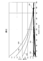
- FIG. 2 is a diagram showing the pressure / discharge rate characteristics of the pump 901.
- the horizontal axis indicates the discharge pressure [mmHg]
- the vertical axis indicates the discharge amount [l (liter) / min].
- a curve 201 is a pressure / discharge amount curve generally shown, which is obtained by averaging the ripple components of the diaphragm pump.
- a curve 202 represents the pressure / discharge amount characteristic at the maximum flow rate when the pump is exhausted.
- a curve 203 represents the pressure / discharge amount characteristic at the minimum flow rate during intake of the pump.
- FIG. 3 is a diagram for explaining problems of the sphygmomanometer 900.
- the horizontal axis indicates the discharge pressure [mmHg]
- the vertical axis indicates the discharge amount [l / min].
- the curve 301 shows the pressure / discharge amount characteristic obtained by averaging the ripple components of the pump.
- the curve 302 indicates the pressure / discharge amount characteristic when the pump is exhausted at the maximum flow rate.
- a curve 303 indicates the pressure / discharge amount characteristic when the pump is at the minimum flow rate during intake, as with the curve 203.
- a straight line 304 shows a load straight line corresponding to the curve 301 when the pump 901 is an electromagnetic valve 903 when the discharge pressure is 50 [mmHg], and a straight line 305 is when the discharge pressure of the pump 901 is 250 [mmHg].
- the load straight line corresponding to the curve 301 of the electromagnetic valve 903 is shown.
- the solenoid valve 903 When the solenoid valve 903 is controlled so that the discharge pressure of the pump 901 becomes 50 mmHg and the load valve 304 is in the state, the intersection of the curve 302 and the straight line 304 is obtained when the pump shifts to the pressure / discharge amount characteristic 302 during exhaust. As shown, the discharge pressure is 50 [mmHg] or more. On the other hand, when the pump shifts during intake, the discharge pressure becomes 50 mmHg or less as indicated by the intersection of the curve 303 and the straight line 304. In order to keep the discharge pressure constant at 50 [mmHg] without being affected by the ripple fluctuation of the pump, it is necessary to control the discharge amount of the electromagnetic valve 903 and change the inclination angle of the load straight line 304 between 304a and 304b.
- the ripple frequency of the pump is determined by the rotational speed and structure of the motor and may be 100 Hz or more. Therefore, the electromagnetic valve 903 needs to realize a change in the inclination of the load straight line 304a to 304b at a speed of 100 [Hz] or more. Further, the larger the angle formed by the load straight lines 304a and 304b, the higher the speed required for the electromagnetic valve 903.
- the discharge pressure of the pump 901 is 250 [mmHg]
- the load straight line to be controlled by the electromagnetic valve 903 is 305.
- the angle formed between 305a and 305b is narrower than that in the case of 5 [mmHg]. That is, the high speed performance required for the electromagnetic valve 903 is relaxed as the pressure increases.
- the sphygmomanometer of the volume compensation method or the like detects a discharge pressure of the pump, a first valve that adjusts the discharge amount of air that is press-fitted from the pump into the cuff, a second valve that adjusts the cuff pressure inside the cuff, and the pump. It has a 1st pressure sensor and a 2nd pressure sensor which detects cuff pressure.
- the sphygmomanometer according to the embodiment can adjust the discharge amount of the pump with the first valve, thereby reducing fluctuations in the discharge amount characteristic of the pump and preventing the cuff pressure from deviating from a desired pressure.
- FIG. 4 is a schematic configuration diagram of a sphygmomanometer according to the embodiment.
- the signal path is indicated by a one-dot chain line.
- the sphygmomanometer 1 includes a pump 11, a cuff 12, a first valve 13, a first pressure sensor 14, a pump connection member 15, a first cuff connection member 16, a second cuff connection member 17, and a light amount detection sensor. 18, a second valve 23, a second pressure sensor 24, and a control device 30.
- the pump 11 is a diaphragm pump in one example, takes in air in the atmosphere, pressurizes it, and discharges the pressurized air to the cuff 12 via the first valve 13 and the like. The pump 11 is started when a start instruction signal indicating a start instruction of the pump 11 is received, and is stopped when a pump stop instruction signal indicating a stop instruction of the pump 11 is received.
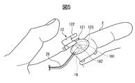
- FIG. 5 is a diagram showing a state in which the cuff 12 is worn on the finger of the person to be measured.
- the cuff 12 has a belt part 121, a cuff fixing part 122, and a contraction fluid bag 123 contained in the belt part, and encloses the index finger 2 of the person to be measured which is a blood pressure measurement part.
- the belt unit 121 further includes a light amount detection sensor 18 having a light emitting element 181 and a light receiving element 182.
- the cuff fixing part 122 is a member that can be rotated between an open position and a fixed position. The index finger 2 of the person to be measured can be inserted when the cuff fixing part 122 is in the open position. Hold index finger 2.
- the contraction fluid bag 123 expands when air, which is a pressure medium, is press-fitted from the pump 11 through a second cuff connection member 26 that is a tubular member formed of a flexible material such as synthetic resin. On the other hand, the contraction fluid bag 123 contracts when air is discharged.
- FIG. 6 is a schematic configuration diagram of the first valve 13.
- arrows A and A ′ indicate the flow of air
- arrow C indicates the moving direction of the actuator 132 of the first valve 13 when a current is supplied to the electromagnetic coil.
- the first valve 13 is an electromagnetic valve having an electromagnetic coil 131, an actuator 132, a valve seat 133, and a current acquisition unit 134.
- the electromagnetic coil 131 generates a magnetic field according to a current input from a power supply device (not shown) via the current acquisition unit 134.
- the generated magnetic field acts so that the magnetic circuit formed by the valve seat 133 and the actuator 132 is closed, and the actuator 132 moves in the closing direction indicated by the arrow C.
- the actuator 132 moves in the closing direction and comes into full contact with the valve seat 133, the first valve is closed.
- the electromagnetic supply to the electromagnetic coil 131 is cut off, the actuator 132 moves in the opening direction opposite to the closing direction indicated by the arrow C by the force of the air flowing in the arrow A.
- the opening degree of the first valve 13 is adjusted by the control device 30 so that the first pressure sensor 14 becomes a set pressure.
- the first valve 13 functions as a throttle valve that adjusts so that the amount of air discharged from the pump 11 to the cuff 12 is always constant regardless of load fluctuations.
- the opening degree of the second valve 23 is adjusted by the control device 30 so that the second pressure sensor 24 becomes a set pressure. Therefore, it functions as a valve that adjusts the cuff pressure by discharging air at a constant flow rate supplied from the first valve and air from the cuff 12.
- the first pressure sensor 14 is, for example, a strain gauge type pressure sensor including a piezoresistive element.
- the first pressure sensor 14 detects the pressure inside the pump connection member 15 disposed between the pump 11 and the first valve.
- the pressure inside the pump connection member 15 is the discharge pressure of the pump 11.
- the discharge pressure of the pump 11 is determined by the discharge flow rate of the pump 11 and the flow rate resistance of the first valve 13.
- the first pressure sensor 14 outputs a discharge pressure signal indicating the detected discharge pressure to the control device 30.
- the second pressure sensor 24 is, for example, a strain gauge type pressure sensor including a piezoresistive element, like the first pressure sensor 14.
- the second pressure sensor 24 detects the cuff pressure inside the cuff 12 via the first cuff connection member 16 and the second cuff connection member 17.
- the cuff pressure is determined by the constant flow rate air supplied from the first valve 13 and the flow rate resistance of the valve of the second valve 23.
- the second pressure sensor 24 outputs a cuff pressure signal indicating the detected cuff pressure to the control device 30.
- FIG. 7 (a) is a perspective view of the pump connection member 15
- FIG. 7 (b) is a perspective view of the first cuff connection member 16
- FIG. 7 (c) is a partial front view of the sphygmomanometer 1.
- the pump connecting member 15 has a pressure chamber 150 formed therein, and a first through-hole 151, a second through-hole 152, and a third through-hole 153 each penetrating from the outer wall 155 to the pressure chamber 150.
- the pump 11 is inserted into the first through hole 151, the first valve 13 is inserted into the second through hole 152, and the first pressure sensor 14 is inserted into the third through hole 153.
- the first cuff connecting member 16 has a pressure chamber 160 formed therein, and the first through-hole 161, the second through-hole 162, the third through-hole 163, and the fourth through each through the outer wall 165 to the pressure chamber 160.
- a through hole 164 is formed.
- the first valve 13 is inserted into the first through hole 161, the second cuff connecting member 17 is inserted into the second through hole 162, the second valve 23 is inserted into the third through hole 163, and the fourth through hole 164 is The second pressure sensor 24 is inserted.
- the second cuff connecting member 17 is a tubular member formed of a flexible material such as synthetic resin, and one end is connected to the cuff 12 and the other end is inserted into the second through hole of the first cuff connecting member 16.
- the total capacity of the inside of the cuff 12, the pressure chamber 160 of the first cuff connecting member 16, and the inside of the second cuff connecting member 17 is 20 [ml] or less.
- the light quantity detection sensor 18 is a photoelectric sensor having a light emitting element 181 and a light receiving element 182, and detects the light quantity when light is applied to the artery of the blood pressure measurement site to which the cuff 902 is attached.
- the light receiving element 182 of the light amount detection sensor 18 receives a light amount corresponding to the amount of hemoglobin flowing through the artery from the light emitting element 181, and outputs a light amount signal indicating the received light amount to the control device 30.
- the light quantity detected by the light quantity detection sensor 18 is arterial volume information related to the arterial volume in the index finger 2 of the measurement subject who is a blood pressure measurement site.
- the light amount detection sensor 18 is an arterial volume information detection sensor that detects arterial volume information related to the arterial volume in the index finger 2 of the measurement subject.
- the control device 30 includes an interface unit 31, a storage unit 32, an input unit 33, an output unit 34, a bus 35, and a processing unit 40.
- the bus 35 connects the storage unit 32, the input unit 33, the output unit 34, and the processing unit 40 so that they can communicate with each other.
- the interface unit 31 includes a first AD converter 311, a second AD converter 312, a third AD converter 313, a first transmission circuit 314, a second transmission circuit 315, and a third transmission circuit 316.
- the first AD converter 311 converts the discharge pressure signal input from the first pressure sensor 14 from an analog signal to a digital signal, and outputs the signal to the processing unit 40 via the bus 35.
- the second AD converter 312 converts the cuff pressure signal input from the second pressure sensor 24 from an analog signal to a digital signal, and outputs the converted signal to the processing unit 40 via the bus 35.
- the third AD converter 313 converts the light amount signal input from the light amount detection sensor 18 from an analog signal to a digital signal and outputs the converted signal to the processing unit 40 via the bus 35.
- the first transmission circuit 314 amplifies the start instruction signal and the pump stop instruction signal and transmits them to the pump 11.
- the second transmission circuit 315 transmits the first valve closing instruction signal and the first valve opening instruction signal to the first valve 13.
- the first valve closing instruction signal indicates that the opening degree of the first valve 13 is decreased by the changed opening degree, and the first valve opening instruction signal indicates that the opening degree of the first valve 13 is increased by the predetermined changing opening degree. It is a signal to show.
- the third transmission circuit 316 transmits the second valve close instruction signal and the second valve open instruction signal to the second valve 23.
- the second valve closing instruction signal indicates that the opening degree of the second valve 23 is decreased, and the second valve opening instruction signal indicates that the opening degree of the second valve 23 is increased.
- the storage unit 32 includes, for example, a semiconductor memory, and stores a driver program, an operating system program, an application program, data, and the like used for arithmetic processing by the processing unit 40.
- the storage unit 32 stores a first set pressure 321, a second set pressure 322, and a set light amount 323.
- the set light amount 323 is determined from the difference between the light amount detected by the light amount detection sensor 18 and the volume compensation value determined by the volume vibration method, and the first set pressure 321 is set as a target value in order to obtain the set light amount 323.
- the first set pressure 321 is 450 [mmHg].
- the second set pressure 322 is a target value of the cuff pressure when the processing unit 40 measures the blood pressure of the measurement subject, and is changed according to the light amount detected by the light amount detection sensor 18.
- the storage unit 32 stores a blood pressure measurement program for measuring the blood pressure of the measurement subject as an application program.
- the computer program may be installed in the storage unit 32 using a known setup program or the like from a computer-readable portable recording medium such as a CD-ROM or DVD-ROM.
- the input unit 33 may be any device that can input data, such as a touch panel and a keyboard.
- the measurement subject can input characters, numbers, symbols, and the like using the input unit 33.
- the input unit 33 When the input unit 33 is operated by the measurement subject, the input unit 33 generates a signal corresponding to the operation. And the produced
- the output unit 34 may be any device as long as it can display images, images, and the like, and is, for example, a liquid crystal display or an organic EL (Electro-Luminescence) display.
- the output unit 34 displays a video corresponding to the video data supplied from the processing unit 40, an image corresponding to the image data, and the like.
- the processing unit 40 includes one or a plurality of processors and their peripheral circuits.
- the processing unit 40 executes various arithmetic processes, and is, for example, a CPU (Central ⁇ ⁇ ⁇ Processing Unit).
- the processing unit 40 controls the interface unit 31 and the like so that various arithmetic processes are executed in an appropriate procedure according to a program and the like stored in the storage unit 32.
- the processing unit 40 executes processing based on programs (driver program, operating system program, application program, etc.) stored in the storage unit 32.
- the processing unit 40 can execute a plurality of programs (such as application programs) in parallel.
- the processing unit 40 includes a blood pressure measurement instruction determination unit 41, a valve opening adjustment unit 42, and a blood pressure measurement unit 43.
- the valve opening adjustment unit 42 includes a discharge pressure acquisition unit 51, a first valve opening adjustment unit 52, a light amount acquisition unit 53, a second set pressure determination unit 54, a cuff pressure acquisition unit 55, and a second valve. And an opening adjustment unit 56.
- Each of these units included in the processing unit 40 is a functional module implemented by a program executed on a processor included in the processing unit 40.
- these units included in the processing unit 40 may be mounted on the sphygmomanometer 1 as an independent integrated circuit, a microprocessor, or firmware.
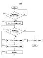
- FIG. 8 is a flowchart of blood pressure measurement processing by the sphygmomanometer 1.
- the blood pressure measurement process shown in FIG. 8 is mainly executed by the processing unit 40 in cooperation with each element of the sphygmomanometer 1 based on a program stored in the storage unit 32 in advance.
- the blood pressure measurement instruction determination unit 41 determines whether or not a blood pressure measurement start instruction has been acquired from the measurement subject via the input unit 33 (S101).
- the blood pressure measurement instruction determination unit 41 repeats the process of S101 until it is determined that a blood pressure measurement start instruction has been acquired (S101—YES).
- the blood pressure measurement instruction determination unit 41 transmits an activation instruction signal indicating the activation instruction of the pump 11 to the pump 11 via the first transmission circuit 314.
- the pump 11 is instructed to start (S102).
- the pump 11 is activated when it receives the activation instruction signal.
- the blood pressure measurement instruction determination unit 41 determines whether or not a blood pressure measurement end instruction has been acquired from the measurement subject via the input unit 33 (S103).
- the valve opening degree adjustment unit 42 adjusts the opening degree of the first valve 13 and the second valve 23.
- the valve opening adjustment unit 42 acquires the discharge pressure of the pump 11 and adjusts the opening of the first valve 13 so that the acquired discharge pressure coincides with the first set pressure (S104).
- valve opening adjustment unit 42 adjusts the opening of the second valve 23 so that the arterial volume obtained from the light quantity acquisition unit 53 matches the volume compensation value (S105).
- the blood pressure measurement unit 43 estimates the cuff pressure when the opening of the second valve 23 is adjusted in S105 as the blood pressure of the measurement subject (S106), and outputs the measured blood pressure via the output unit 34. To do.
- the blood pressure measurement instruction determination unit 41 determines that the blood pressure measurement end instruction has been acquired (S103-YES)
- the blood pressure measurement instruction determination unit 41 transmits a stop instruction signal indicating a stop instruction of the pump 11 to the pump 11 via the first transmission circuit 314. By transmitting, the pump 11 is instructed to stop (S102).
- the pump 11 receives the stop instruction signal, the pump 11 stops.
- FIG. 9 is a flowchart showing more detailed processing of the processing shown in S104.
- the discharge pressure acquisition unit 51 acquires the discharge pressure of the pump 11 corresponding to the discharge pressure signal transmitted from the first pressure sensor 14 via the first AD converter 311 (S201).
- the first valve opening adjustment unit 52 determines whether or not the acquired discharge pressure matches the first set pressure 321 stored in the storage unit 32 (S202). If the first valve opening adjustment unit 52 determines that the acquired discharge pressure does not match the first set pressure 321 stored in the storage unit 32 (S202—NO), the acquired discharge pressure is stored in the storage unit 32. It is determined whether or not it is less than the first set pressure 321 (S203).
- the first valve opening adjustment unit 52 transmits a first valve opening instruction signal to the second transmission. This is transmitted to the first valve 13 via the circuit 315 (S204).
- the first valve 13 increases the opening by a predetermined change opening, and the process returns to S201.
- the first valve opening adjustment unit 52 determines that the acquired discharge pressure is larger than the first set pressure 321 stored in the storage unit 32 (S203—NO)
- the first valve opening adjustment unit 52 outputs the first valve closing instruction signal to the second It transmits to the 1st valve
- the first valve 13 decreases the opening by a predetermined change opening, and the process returns to S201.
- the processes of S201 to S205 are repeated until it is determined that the acquired discharge pressure matches the first set pressure 321 stored in the storage unit 32 (S202—YES).
- the first valve opening degree adjustment unit 52 causes the opening degree of the first valve 13 so that the discharge pressure of the pump 11 matches the first set pressure stored in the storage unit 32. Adjust. If the first valve opening adjustment unit 52 determines that the discharge pressure of the pump 11 matches the first set pressure 321 stored in the storage unit 32 (S202—YES), the process is performed while maintaining the first valve opening. Return to S201.
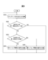
- FIG. 10 is a flowchart showing more detailed processing of the processing shown in S105.
- the light quantity acquisition unit 53 acquires the light quantity corresponding to the light quantity signal transmitted from the light quantity detection sensor 18 via the third AD converter 313 (S301).
- the second valve opening adjustment unit 56 determines whether or not the light amount acquired in S301 matches the set light amount 323 stored in the storage unit 32 (S302). If the second valve opening adjustment unit 56 determines that the light amount acquired in S301 does not match the set light amount 323 stored in the storage unit 32 (S302—NO), the light amount acquired in S301 is stored in the storage unit 32. It is determined whether or not the set light amount is less than 323 stored in (S303).
- the second valve opening adjustment unit 56 determines that the acquired light amount is less than the set light amount 323 stored in the storage unit 32 (S303—YES)
- the second valve opening instruction signal is sent to the third transmission circuit 316.
- the second valve 23 receives the second valve opening instruction signal
- the second valve 23 increases the opening by a predetermined change opening.
- the cuff pressure acquisition unit 55 acquires the cuff pressure inside the cuff 12 corresponding to the cuff pressure signal transmitted from the second pressure sensor 24 via the second AD converter 312 (S311), and the acquired cuff pressure is It is determined whether or not it matches the predetermined opening (second set pressure 322) (S307). If they match, the process returns to step S301.
- the second valve opening adjustment unit 56 determines that the acquired light amount is larger than the set light amount 323 stored in the storage unit 32 (S303—NO)
- the second valve closing instruction signal is transmitted to the third transmission circuit 316.
- the second valve 23 receives the second valve close instruction signal
- the second valve 23 decreases the opening by a predetermined change opening.
- the cuff pressure acquisition unit 55 acquires the cuff pressure inside the cuff 12 corresponding to the cuff pressure signal transmitted from the second pressure sensor 24 via the second AD converter 312 (S310). It is determined whether the acquired cuff pressure matches a predetermined opening (second set pressure) (S306). If they match, the process returns to step S301.
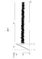
- FIG. 11 is a diagram showing an example of the operation of the sphygmomanometer 1.
- the horizontal axis indicates the elapsed time t [s]
- the vertical axis indicates the cuff pressure Pc [mmHg] inside the cuff 12.
- the blood pressure measurement instruction determination unit 41 determines that a blood pressure measurement start instruction has been acquired from the measurement subject (S101), and instructs the pump 11 to start (S102).
- the pump 11 is activated when it receives the activation instruction signal.
- the cuff pressure Pc inside the cuff 12 increases rapidly on the vertical axis.
- the valve opening adjustment unit 42 acquires the discharge pressure of the pump 11, and adjusts the opening of the first valve 13 so that the acquired discharge pressure matches the first set pressure (S104). .
- a period t3 between time t1 and time t2 is a preparation period until the sphygmomanometer 1 starts blood pressure measurement processing.
- a period t4 after t2 is a blood pressure measurement period in which the sphygmomanometer 1 continuously measures the blood pressure of the measurement subject.
- the processes of S103 to S106 are repeated, so that the cuff pressure Pc varies according to the pulse of the measurement subject.
- the sphygmomanometer 1 becomes a constant flow output by maintaining the discharge pressure of the pump 11 in the vicinity of the first set pressure.
- the fluctuation of the discharge amount of the pump 11 due to the ripple of the pump can be reduced, and the second valve 23 can be dedicated to cuff pressure control. That is, in the sphygmomanometer 1, high-speed control of the cuff pressure required when continuously measuring the blood pressure of the measurement subject can be realized even by using a general-purpose electromagnetic valve.
- FIG. 12 is a diagram showing the pressure / discharge rate characteristics of the pump 11.
- the horizontal axis indicates the discharge pressure [mmHg]
- the vertical axis indicates the discharge amount [l / min].
- a curve 1301 indicates the curve 301 shown in FIG. 3
- a curve 1302 indicates the curve 302 shown in FIG. 3
- a curve 1303 indicates the curve 303 shown in FIG.
- Curves 1301 to 1303 indicate the pressure / discharge amount characteristics of the pump 901 of the sphygmomanometer 900 described with reference to FIGS.
- the discharge pressure of the pump 11 is adjusted to 450 [mmHg] by the first valve 13, the discharge amount of the pump 11 becomes constant at about 0.18 [ml] as shown in FIG. .
- the load straight line of the first valve 13 used here falls within the range 1306, and the angle formed by the two load straight lines is narrow, which can be realized by a relatively low speed electromagnetic valve.
- the cuff pressure to be changed following the change in the arterial pressure of the human needs only to have a followability of about 20 [Hz].
- the range of the load straight line of the second valve 23 when the cuff pressure is varied in the range of 50 [mmHg] to 250 [mmHg] is wide, but the followability within this range is required to be about 20 Hz.
- the range of the load straight line of the second valve 23 is the load straight line range 1304 at the cuff pressure 50 [mmHg] and the load straight line 1305 at the cuff pressure 250 [mmHg]. In either case, the angle formed by the two load straight lines is narrow, and a valve with a relatively slow response speed can be used as the second valve 23, so that the cost can be reduced.
- the sphygmomanometer 1 is connected to the cuff 12 via the first cuff connection member 16 in which the first valve 13, the second cuff connection member 17, the second valve 23, and the second pressure sensor 24 are inserted into the four through holes. Since the first valve 13 is connected, the volume to which the cuff pressure is applied can be reduced. In the sphygmomanometer 1, since the volume to which the cuff pressure is applied is small, a large change in the cuff pressure can be realized by a small change in the discharge amount of the pump 11.
Abstract
Description
図1は、関連する血圧計の概略構成図である。図1において、信号の経路は一点鎖線で示される。 (Configuration and function of related blood pressure monitor)
FIG. 1 is a schematic configuration diagram of a related sphygmomanometer. In FIG. 1, a signal path is indicated by a one-dot chain line.
実施形態に係る容積補償法等の血圧計に於いてカフ圧制御を安価な汎用電磁バルブを用いてダイヤフラムポンプのリップルを含む高速圧力制御を実現するものである。実施形態に係る血圧計は、ポンプからカフの内部に圧入される空気の吐出量を調整する第1バルブと、カフの内部のカフ圧力を調整する第2バルブと、ポンプの吐出圧力を検出する第1圧力センサと、カフ圧力を検出する第2圧力センサとを有する。実施形態に係る血圧計は、第1バルブでポンプの吐出量を調整することで、ポンプの吐出量特性の変動を低減し、カフ圧が所望の圧力から乖離することを防止ができる。 (Overview of blood pressure monitor according to the embodiment)
In the sphygmomanometer of the volume compensation method or the like according to the embodiment, high-speed pressure control including ripples of a diaphragm pump is realized by using an inexpensive general-purpose electromagnetic valve for cuff pressure control. The sphygmomanometer according to the embodiment detects a discharge pressure of the pump, a first valve that adjusts the discharge amount of air that is press-fitted from the pump into the cuff, a second valve that adjusts the cuff pressure inside the cuff, and the pump. It has a 1st pressure sensor and a 2nd pressure sensor which detects cuff pressure. The sphygmomanometer according to the embodiment can adjust the discharge amount of the pump with the first valve, thereby reducing fluctuations in the discharge amount characteristic of the pump and preventing the cuff pressure from deviating from a desired pressure.
図8は、血圧計1による血圧測定処理のフローチャートである。図8に示す血圧測定処理は、予め記憶部32に記憶されているプログラムに基づいて、主に処理部40により、血圧計1の各要素と協働して実行される。 (Blood pressure measurement process by the sphygmomanometer according to the embodiment)
FIG. 8 is a flowchart of blood pressure measurement processing by the
血圧計1は、ポンプ11の吐出圧力を第1設定圧力の近傍で維持することにより定流量出力となる。第1バルブ13でポンプ11の吐出量を調整することで、ポンプが有するリップルに伴うポンプ11の吐出量の変動を低減し、第2バルブ23はカフ圧制御に専念出来る。すなわち、血圧計1では、被測定者の血圧を連続して測定するときに要求されるカフ圧力の高速制御が汎用電磁バルブを用いても実現可能とする。 (Operational effect of the blood pressure monitor according to the embodiment)
The
11 ポンプ
12 カフ
13 第1バルブ
14 第1圧力センサ
15 ポンプ接続部材
16 第1カフ接続部材
17 第2カフ接続部材
18 光量検出センサ(動脈容積情報検出センサ)
23 第2バルブ
24 第2圧力センサ
30 制御装置
31 インタフェース部
32 記憶部
40 処理部
41 血圧測定指示判定部
42 バルブ開度調整部
43 血圧測定部 DESCRIPTION OF
23
Claims (4)
- ポンプと、
被測定者の血圧測定部位に装着されたカフと、
前記ポンプと前記カフとの間に配置され、開度を調整することで前記ポンプの吐出量を調整可能な第1バルブと、
開度を調整することで前記カフの内部のカフ圧力を調整可能な第2バルブと、
前記ポンプの吐出圧力を検出する第1圧力センサと、
前記カフ圧力を検出する第2圧力センサと、
被測定者の前記血圧測定部位における動脈の容積に関連する動脈容積情報を検出する動脈容積情報検出センサと、
前記吐出圧力及び前記カフ圧力、並びに前記動脈容積情報を取得し、第1バルブ及び第2バルブの開度を調整するとバルブ開度調整部と、
前記カフ圧力に基づいて被測定者の血圧を測定する血圧測定部と、
を有する血圧計。 A pump,
A cuff attached to the blood pressure measurement site of the subject,
A first valve disposed between the pump and the cuff and capable of adjusting a discharge amount of the pump by adjusting an opening;
A second valve capable of adjusting the cuff pressure inside the cuff by adjusting the opening;
A first pressure sensor for detecting a discharge pressure of the pump;
A second pressure sensor for detecting the cuff pressure;
An arterial volume information detection sensor for detecting arterial volume information related to the volume of the artery at the blood pressure measurement site of the measurement subject;
Acquiring the discharge pressure and the cuff pressure, and the arterial volume information, adjusting the opening of the first valve and the second valve, a valve opening adjustment unit,
A blood pressure measurement unit that measures the blood pressure of the measurement subject based on the cuff pressure;
Blood pressure monitor. - 前記バルブ開度調整部は、前記吐出圧力が第1設定圧力に一致するように前記第1バルブの開度を調整する第1バルブ開度調整部を有する、請求項1に記載の血圧計。 The sphygmomanometer according to claim 1, wherein the valve opening adjustment unit includes a first valve opening adjustment unit that adjusts the opening of the first valve so that the discharge pressure coincides with a first set pressure.
- 前記バルブ開度調整部は、
前記血圧測定部位における動脈の容積が一定になるように第2設定圧力を決定する第2設定圧力決定部と、
前記カフ圧力が第2設定圧力に一致するように前記第2バルブの開度を調整する第2バルブ開度調整部と、を更に有する、請求項2に記載の血圧計。 The valve opening adjustment unit is
A second set pressure determining unit that determines a second set pressure so that the volume of the artery at the blood pressure measurement site is constant;
The sphygmomanometer according to claim 2, further comprising: a second valve opening degree adjusting unit that adjusts an opening degree of the second valve so that the cuff pressure coincides with a second set pressure. - 内部に圧力室が形成されると共に、それぞれが外壁から前記圧力室まで貫通する第1貫通孔、第2貫通孔、第3貫通孔、及び第4貫通孔が形成された第1カフ接続部材と、
前記第1カフ接続部材と前記カフとを接続する第2カフ接続部材と、を更に有し、
前記第1貫通孔は前記第1バルブが挿入され、
前記第2貫通孔は前記第2カフ接続部材が挿入され、
前記第3貫通孔は前記第2バルブが挿入され、
前記第4貫通孔は前記第2圧力センサが挿入された、請求項1~3の何れか一項に記載の血圧計。 A first cuff connecting member in which a pressure chamber is formed and a first through hole, a second through hole, a third through hole, and a fourth through hole are formed, each penetrating from the outer wall to the pressure chamber; ,
A second cuff connecting member that connects the first cuff connecting member and the cuff;
The first valve is inserted into the first through hole,
The second cuff connecting member is inserted into the second through hole,
The third valve is inserted into the third through hole,
The sphygmomanometer according to any one of claims 1 to 3, wherein the second pressure sensor is inserted into the fourth through hole.
Priority Applications (4)
| Application Number | Priority Date | Filing Date | Title |
|---|---|---|---|
| PCT/JP2016/062410 WO2017183112A1 (en) | 2016-04-19 | 2016-04-19 | Blood pressure meter |
| EP16899386.3A EP3446627A4 (en) | 2016-04-19 | 2016-04-19 | Blood pressure meter |
| JP2018512685A JP6717374B2 (en) | 2016-04-19 | 2016-04-19 | Sphygmomanometer |
| US16/138,586 US11045097B2 (en) | 2016-04-19 | 2018-09-21 | Blood pressure meter |
Applications Claiming Priority (1)
| Application Number | Priority Date | Filing Date | Title |
|---|---|---|---|
| PCT/JP2016/062410 WO2017183112A1 (en) | 2016-04-19 | 2016-04-19 | Blood pressure meter |
Related Child Applications (1)
| Application Number | Title | Priority Date | Filing Date |
|---|---|---|---|
| US16/138,586 Continuation US11045097B2 (en) | 2016-04-19 | 2018-09-21 | Blood pressure meter |
Publications (1)
| Publication Number | Publication Date |
|---|---|
| WO2017183112A1 true WO2017183112A1 (en) | 2017-10-26 |
Family
ID=60115756
Family Applications (1)
| Application Number | Title | Priority Date | Filing Date |
|---|---|---|---|
| PCT/JP2016/062410 WO2017183112A1 (en) | 2016-04-19 | 2016-04-19 | Blood pressure meter |
Country Status (4)
| Country | Link |
|---|---|
| US (1) | US11045097B2 (en) |
| EP (1) | EP3446627A4 (en) |
| JP (1) | JP6717374B2 (en) |
| WO (1) | WO2017183112A1 (en) |
Families Citing this family (2)
| Publication number | Priority date | Publication date | Assignee | Title |
|---|---|---|---|---|
| TWI611103B (en) * | 2016-02-03 | 2018-01-11 | 研能科技股份有限公司 | Control method of driving circuit of piezoelectric actuated pump and driving circuit thereof |
| WO2024077254A1 (en) * | 2022-10-07 | 2024-04-11 | Edwards Lifesciences Corporation | Systems and methods for responsive damping of pressure |
Citations (12)
| Publication number | Priority date | Publication date | Assignee | Title |
|---|---|---|---|---|
| US4406289A (en) | 1980-09-12 | 1983-09-27 | Nederlandse Centrale Organisatie Voor Toegepast-Natuurwetenschappelijk | Device for the indirect, non-invasive and continuous measurement of blood pressure |
| JPS6141434A (en) * | 1984-08-02 | 1986-02-27 | コーリン電子株式会社 | Non-observation type continuous blood pressure measuring method and apparatus |
| JPS61119238A (en) * | 1984-11-14 | 1986-06-06 | コーリン電子株式会社 | Blood pressure measuring apparatus |
| JPS6329616A (en) | 1986-07-23 | 1988-02-08 | 中根 央 | Continuous blood pressure measuring apparatus |
| JPH01201231A (en) * | 1988-02-05 | 1989-08-14 | Gakken Co Ltd | Non-invasive continuous blood pressure measuring instrument by photoelectric volume pulse wave |
| JPH0549605A (en) | 1992-01-18 | 1993-03-02 | Colleen Denshi Kk | Non-blood view type continuous blood pressure measuring instrument |
| JPH08332173A (en) | 1995-06-07 | 1996-12-17 | Hioki Ee Corp | Sphygmomanometry by bloodless type sphygmomanometer |
| JP2000515789A (en) * | 1996-07-30 | 2000-11-28 | イタマール メディカル(シー.エム)1997 リミテッド | Method and apparatus for non-invasive examination of medical conditions by monitoring peripheral artery sounds |
| US6669648B1 (en) | 1999-03-30 | 2003-12-30 | Cnsystems Medizintechnik Gmbh | Continuous non-invasive sphygmomanometer |
| JP2007503223A (en) * | 2003-08-22 | 2007-02-22 | エプコール,インク. | Non-invasive blood pressure monitoring apparatus and method |
| JP2012205719A (en) | 2011-03-29 | 2012-10-25 | Fukuda Denshi Co Ltd | Sphygmomanometer |
| JP2015188646A (en) | 2014-03-28 | 2015-11-02 | テルモ株式会社 | Blood pressure measuring device |
Family Cites Families (8)
| Publication number | Priority date | Publication date | Assignee | Title |
|---|---|---|---|---|
| NL8104879A (en) * | 1981-10-28 | 1983-05-16 | Tno | METHOD AND APPARATUS FOR CONTROLLING THE CUFF PRESSURE WHEN MEASURING THE FINGER BLOOD PRESSURE WITH A PHOTO-ELECTRICAL PLETHYSMOGRAPH. |
| NL8105381A (en) * | 1981-11-27 | 1983-06-16 | Tno | METHOD AND APPARATUS FOR CORRECTING THE CUFF PRESSURE IN MEASURING THE BLOOD PRESSURE IN A BODY PART USING A PLETHYSMOGRAPH. |
| AT412702B (en) | 2003-10-21 | 2005-06-27 | Cnsystems Medizintechnik Gmbh | DEVICE AND METHOD FOR CONTROLLING THE PRESSURE IN AN INFLATABLE CUFF OF A BLOOD PRESSURE METER |
| US20110263992A1 (en) * | 2008-10-29 | 2011-10-27 | Ilja Guelen | blood pressure measurement device, a front end, an inflatable body and a computer program product |
| EP2319408A1 (en) * | 2009-10-15 | 2011-05-11 | Finapres Medical Systems B.V. | Device for controlling the pressure in an inflatable pressure pad |
| JP2012210374A (en) * | 2011-03-31 | 2012-11-01 | Omron Healthcare Co Ltd | Cuff for blood pressure information measurement device and the blood pressure information measurement device including the same |
| EP2732759A1 (en) * | 2012-11-19 | 2014-05-21 | Jerusalem College of Technology | System and method of measurement of systolic blood pressure |
| US10945612B2 (en) * | 2014-04-03 | 2021-03-16 | The Regents Of The University Of California | Assessing endothelial function using a blood pressure cuff |
-
2016
- 2016-04-19 WO PCT/JP2016/062410 patent/WO2017183112A1/en active Application Filing
- 2016-04-19 JP JP2018512685A patent/JP6717374B2/en active Active
- 2016-04-19 EP EP16899386.3A patent/EP3446627A4/en not_active Withdrawn
-
2018
- 2018-09-21 US US16/138,586 patent/US11045097B2/en active Active
Patent Citations (12)
| Publication number | Priority date | Publication date | Assignee | Title |
|---|---|---|---|---|
| US4406289A (en) | 1980-09-12 | 1983-09-27 | Nederlandse Centrale Organisatie Voor Toegepast-Natuurwetenschappelijk | Device for the indirect, non-invasive and continuous measurement of blood pressure |
| JPS6141434A (en) * | 1984-08-02 | 1986-02-27 | コーリン電子株式会社 | Non-observation type continuous blood pressure measuring method and apparatus |
| JPS61119238A (en) * | 1984-11-14 | 1986-06-06 | コーリン電子株式会社 | Blood pressure measuring apparatus |
| JPS6329616A (en) | 1986-07-23 | 1988-02-08 | 中根 央 | Continuous blood pressure measuring apparatus |
| JPH01201231A (en) * | 1988-02-05 | 1989-08-14 | Gakken Co Ltd | Non-invasive continuous blood pressure measuring instrument by photoelectric volume pulse wave |
| JPH0549605A (en) | 1992-01-18 | 1993-03-02 | Colleen Denshi Kk | Non-blood view type continuous blood pressure measuring instrument |
| JPH08332173A (en) | 1995-06-07 | 1996-12-17 | Hioki Ee Corp | Sphygmomanometry by bloodless type sphygmomanometer |
| JP2000515789A (en) * | 1996-07-30 | 2000-11-28 | イタマール メディカル(シー.エム)1997 リミテッド | Method and apparatus for non-invasive examination of medical conditions by monitoring peripheral artery sounds |
| US6669648B1 (en) | 1999-03-30 | 2003-12-30 | Cnsystems Medizintechnik Gmbh | Continuous non-invasive sphygmomanometer |
| JP2007503223A (en) * | 2003-08-22 | 2007-02-22 | エプコール,インク. | Non-invasive blood pressure monitoring apparatus and method |
| JP2012205719A (en) | 2011-03-29 | 2012-10-25 | Fukuda Denshi Co Ltd | Sphygmomanometer |
| JP2015188646A (en) | 2014-03-28 | 2015-11-02 | テルモ株式会社 | Blood pressure measuring device |
Non-Patent Citations (1)
| Title |
|---|
| See also references of EP3446627A4 |
Also Published As
| Publication number | Publication date |
|---|---|
| JP6717374B2 (en) | 2020-07-01 |
| EP3446627A4 (en) | 2019-10-09 |
| US20190014998A1 (en) | 2019-01-17 |
| US11045097B2 (en) | 2021-06-29 |
| JPWO2017183112A1 (en) | 2019-02-28 |
| EP3446627A1 (en) | 2019-02-27 |
Similar Documents
| Publication | Publication Date | Title |
|---|---|---|
| JP3495348B2 (en) | Pulse wave velocity information measurement device | |
| US6869403B2 (en) | Blood-pressure determining apparatus | |
| US8905940B2 (en) | Flow rate control valve and blood pressure information measurement device including the same | |
| EP0818176A1 (en) | Pressure pulse wave detecting apparatus | |
| US9072436B2 (en) | Device for measuring information regarding blood pressure | |
| JPH0614892A (en) | Blood pressure monitor device equipped with finger cuff calibration device | |
| JP2007007075A (en) | Blood pressure measuring apparatus | |
| JP2013507210A (en) | Equipment for pressure control in inflatable pressure pads | |
| WO2019016192A1 (en) | An apparatus for measuring a physiological parameter using a wearable sensor | |
| JP6370186B2 (en) | Biological information measuring device | |
| WO2017047541A1 (en) | Biometric information measuring device, biometric information measuring method, and biometric information measuring program | |
| WO2019054254A1 (en) | Display control device and program | |
| WO2017183112A1 (en) | Blood pressure meter | |
| US20040171940A1 (en) | Arteriostenosis diagnosing apparatus | |
| US6802814B2 (en) | Pressure-pulse-wave detecting apparatus | |
| JPH04279147A (en) | Automatic sphygmomanometer | |
| JPH04256727A (en) | Blood pressure detector | |
| EP1332716A1 (en) | Inferior-and-superior-limb blood-pressure-index measuring apparatus | |
| US6808497B2 (en) | Blood-pressure measuring apparatus and inferior-and-superior-limb blood-pressure-index measuring apparatus | |
| US20040171941A1 (en) | Blood flow amount estimating apparatus | |
| JP2021501658A (en) | Non-invasive blood pressure measuring device | |
| JP2011104208A (en) | Pulse wave propagation velocity measuring device | |
| JPS58127634A (en) | Apparatus for controlling pressure change and speed of manschet in hemomanometer apparatus | |
| US7056291B2 (en) | Arteriosclerosis evaluating apparatus | |
| JP3530893B2 (en) | Atherosclerosis evaluation device |
Legal Events
| Date | Code | Title | Description |
|---|---|---|---|
| ENP | Entry into the national phase |
Ref document number: 2018512685 Country of ref document: JP Kind code of ref document: A |
|
| NENP | Non-entry into the national phase |
Ref country code: DE |
|
| WWE | Wipo information: entry into national phase |
Ref document number: 2016899386 Country of ref document: EP |
|
| ENP | Entry into the national phase |
Ref document number: 2016899386 Country of ref document: EP Effective date: 20181119 |
|
| 121 | Ep: the epo has been informed by wipo that ep was designated in this application |
Ref document number: 16899386 Country of ref document: EP Kind code of ref document: A1 |