WO2017179912A1 - Appareil et procédé destiné à un dispositif d'affichage transparent de vidéo augmentée d'informations tridimensionnelles, et appareil de rectification - Google Patents
Appareil et procédé destiné à un dispositif d'affichage transparent de vidéo augmentée d'informations tridimensionnelles, et appareil de rectification Download PDFInfo
- Publication number
- WO2017179912A1 WO2017179912A1 PCT/KR2017/003973 KR2017003973W WO2017179912A1 WO 2017179912 A1 WO2017179912 A1 WO 2017179912A1 KR 2017003973 W KR2017003973 W KR 2017003973W WO 2017179912 A1 WO2017179912 A1 WO 2017179912A1
- Authority
- WO
- WIPO (PCT)
- Prior art keywords
- module
- current
- information
- difference value
- images
- Prior art date
Links
Images


Classifications
-
- G—PHYSICS
- G06—COMPUTING; CALCULATING OR COUNTING
- G06T—IMAGE DATA PROCESSING OR GENERATION, IN GENERAL
- G06T19/00—Manipulating 3D models or images for computer graphics
-
- H—ELECTRICITY
- H04—ELECTRIC COMMUNICATION TECHNIQUE
- H04N—PICTORIAL COMMUNICATION, e.g. TELEVISION
- H04N13/00—Stereoscopic video systems; Multi-view video systems; Details thereof
-
- H—ELECTRICITY
- H04—ELECTRIC COMMUNICATION TECHNIQUE
- H04N—PICTORIAL COMMUNICATION, e.g. TELEVISION
- H04N13/00—Stereoscopic video systems; Multi-view video systems; Details thereof
- H04N13/20—Image signal generators
Definitions
- Embodiments of the present invention relate to a three-dimensional information augmented video see-through display apparatus and method and a rectification apparatus for the same.
- a head mounted display (HMD) device is an image display device that can be worn on a head, such as glasses, to view an image, and is a next generation image display device that is used for viewing a large screen and performing surgery or diagnosis while carrying.
- Conventional HMDs have been used for special purposes such as military and training purposes, but as HMDs become smaller and lighter due to the development of display technology, low-priced HMDs are commercially available. These low-cost HMDs have been used mainly for 3D movie watching until recently, but are actively researching and developing them as visualization devices for virtual reality and augmented reality by doubling the technical characteristics that can provide high immersion.
- HMD Video See-Through Head Mounted Display
- the real world image (real image) acquired through the camera is converted into a digital signal and visualized by HMD. In this way, the user sees the real world in front as a digital image.
- Video see-through HMDs have several benefits. Firstly, information that cannot be seen with the naked eye, such as infrared, ultraviolet, ultrasonic, and electromagnetic waves, can be visually identified using a special camera. In addition, by using the zoom-in function of the camera, a far object can be magnified from several times to several tens of times. In addition, when the fisheye lens is mounted on the camera, the viewing angle may be greatly widened to provide an omnidirectional view.
- the video see-through HMD can store the front view as seen by the user as a stereoscopic image.
- the saved video information can be shared with others through the network, and the user can view it again in the future. This storage of visual experiences allows users to play / share experiences beyond time and space constraints.
- video see-through HMDs provide the ability to protect the user's eyes from the risk of damaging vision, such as sunlight, lasers, dirt, and hazardous materials.
- network means including video see-through HMD, wireless video communications and the Internet
- a visual experience sharing system that can be put to practical use in the near future will be possible. Accordingly, there is a need for a technology development of a smooth information service that enables sharing of visual experiences among these various benefits that can be obtained when using a video see-through HMD.
- An object of the present invention is to generate a three-dimensional image for virtual reality or augmented reality in a video see-through method by processing the three-dimensional image in a module implemented by a hardware chip without the help of a PC from the plurality of camera modules.
- the present invention provides a three-dimensional information enhancement video see-through display device and method.
- an object of the present invention is to reduce the storage space of the breakpoint lookup table by sequentially storing a plurality of breakpoint information for rectification, the empty space on the breakpoint lookup table.
- an object of the present invention is to store the difference value between the next target coordinate and the current target coordinate, which are coordinates to be transformed, in advance in the current coordinate transformation information for rectification, in the breakpoint lookup table. This is to perform redirection by minimizing access.
- the three-dimensional information augmented video see-through display device is a camera interface module for obtaining at least two real images from at least two camera modules, A rectification module that performs rectification, combining the virtual image into each of the at least two real images based on a lens distortion compensation value representing a value for compensating for the distortion of the wide-angle lens for the at least two real images Lens distortion compensation module correcting at least two composite images and side by side image processing on at least two composite images to generate a three-dimensional image for virtual reality (VR) or augmented reality (AR). It includes an image generation module for generating.
- VR virtual reality
- AR augmented reality
- the rectification module may be configured to perform coordinate transformation equal to each other among a plurality of pixels included in each of the at least two real images based on the current reference target break point information on a previously stored break point lookup table.
- a current coordinate transformation target pixel group consisting of at least one consecutive pixel required, each of which is determined, and each coordinate coordinate transformation target pixel group includes a current coordinate value including a current difference value that is a difference value from a current target coordinate that is a coordinate to be converted Based on the conversion information, coordinates of each pixel group of the current coordinate conversion target are converted.
- the pre-stored breakpoint lookup table may sequentially store a plurality of breakpoint information in an empty space on the memory, and at least one memory of at least one breakpoint information among the plurality of sequentially stored breakpoint information. More storage address information.
- the current coordinate transformation information may be a next difference that is a difference value with a next target coordinate that is a coordinate to be transformed, respectively, based on the next reference target breakpoint information on the previously stored breakpoint lookup table.
- the difference value between the value and the current difference value is stored in advance.
- the rectification module converts the coordinates of each of the next coordinate conversion target pixel groups based on the difference between the next difference value and the current difference value.
- a differential field which is a field indicating a current difference value, includes at least four bits.
- the three-dimensional information augmented video see-through display device improves image processing reliability for at least two camera modules for taking at least two real images, an infrared camera module for taking infrared images and at least two real images.
- the apparatus may further include a camera calibration module that performs camera calibration on at least two camera modules based on the infrared image.
- the three-dimensional information augmentation video see-through display device is a light detection module for detecting a light position within a certain radius of the current position based on the current position and the direction data for each light based on the current position based on the detected light position.
- the apparatus further includes a spatial generating module for generating a virtual image, wherein the virtual image is input from a computer that is interoperable with the three-dimensional information augmentation video see-through display device and combined with each of at least two real images. Gives an object a shadow effect.
- the light detection module further detects illuminance of each light for each light position, and the computer adjusts a shadow depth of an object in the virtual image based on the detected illuminance when applying a shadow effect.
- the three-dimensional information augmented video see-through display apparatus further includes a microphone module for detecting a sound generated within a predetermined radius based on the current position and a communication module for transmitting the detected sound to a preset sound transmission target.
- the module when there are a plurality of microphone modules, based on azimuth azimuth of each of the plurality of microphone modules, further comprising a sense of space generating module for generating the direction data of the sound sensed by each of the plurality of microphone modules, communication The module further transmits the generated direction data to the sound transmission object.
- the 3D information enhancement video see-through display device further includes a lens distortion compensation lookup table that stores lens distortion compensation values matched for each of the plurality of display devices, and the lens distortion compensation module uses at least two lens distortion compensation lookup tables. The two composite images.
- At least one of the camera interface module, the rectification module, the lens distortion compensation module, and the image generating module is implemented as a hardware chip.
- the three-dimensional information augmented video see-through display method is to obtain at least two real images from at least two camera modules, rectification for at least two real images performing a rectification, based on a lens distortion compensation value representing a value for compensating for distortion of the wide-angle lens for at least two real images, at least two composite images combining the virtual image into each of the at least two real images Correcting and generating a 3D image for virtual reality (VR) or augmented reality (AR) by performing side by side image processing on the at least two composite images.
- VR virtual reality
- AR augmented reality
- the step of performing rectification may include transforming coordinates identical to each other among a plurality of pixels included in each of the at least two real images based on the current reference target break point information on a pre-stored break point lookup table. Determining a current coordinate transformation target pixel group composed of at least one continuous pixel required, and each current coordinate transformation target pixel group including a current difference value that is a difference value from a current target coordinate that is a coordinate to be converted. And converting the coordinates of each pixel group of the current coordinate transformation target based on the current coordinate transformation information.
- the current coordinate transformation information is a difference value from a next target coordinate, which is a coordinate to which each of the next coordinate transformation target pixel groups predetermined based on the next reference target breakpoint information on the pre-stored breakpoint lookup table is converted.
- the difference between the next difference and the current difference is stored in advance.
- the three-dimensional information augmentation video see-through display method detects an illumination position within a predetermined radius based on the current position, and generates directional data for each illumination based on the current position based on the detected illumination position. And applying a shading effect to the object in the virtual image based on the generated direction data.
- the 3D information enhancement video see-through display method may further include storing lens distortion compensation values matched for each of the plurality of display apparatuses in a lens distortion compensation lookup table, and correcting the lens distortion compensation lookup table. And correcting the at least two composite images using.
- a rectification apparatus is a rectification (rectification) for at least two real images and a camera interface module for obtaining at least two real images from at least two camera modules
- a repetition module for performing a) wherein the repetition module includes a plurality of pixels included in each of the at least two actual images based on current reference target break point information on a pre-stored break point lookup table.
- each pixel group of the current coordinate conversion target It converts the coordinates.
- a three-dimensional image for virtual reality or augmented reality in a video see-through method can be generated.
- the processing reliability can be improved.
- rectification may be performed on images captured from a plurality of camera modules to change the plurality of captured images as if they were captured from a camera arranged on the same column. This can provide high quality images.
- the image quality can be improved by adding an opposite distortion to the image incident through the wide-angle lens.
- a virtual image to be combined with a photographed image by detecting a surrounding light position and illumination of each light position through a light sensing module such as a CDS, and using the detection result.
- a light sensing module such as a CDS
- the other party by sensing the surrounding sound and the azimuth angle to which the sound is directed through the microphone module, and using the result of the detection to transmit the sound having a directionality to the other party, the other party to see the atmosphere of the field Make it feel vivid.
- the mounting base may be detachably installed on various display devices through fastening of the mounting base and the cover.
- the storage space of the breakpoint lookup table may be reduced by sequentially storing empty spaces on the breakpoint lookup table for the plurality of breakpoint information for rectification.
- the break point lookup table by previously storing a difference value between a next target coordinate and a current target coordinate, which are coordinates to be transformed, in the current coordinate transformation information for rectification, respectively. This can be done by minimizing access to.
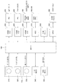
- FIG. 1 is a block diagram illustrating a three-dimensional information augmentation video see-through display device according to an embodiment of the present invention.
- FIG. 2 is a diagram illustrating an operation of a three-dimensional information augmentation video see-through display device according to an embodiment of the present invention.
- FIG. 3 is a PCB block diagram illustrating a connection state between a control unit and a peripheral device of a 3D information enhanced video see-through display device according to an embodiment of the present invention.
- 4 to 6 are flowcharts illustrating a three-dimensional information augmentation video seed display method according to an embodiment of the present invention.
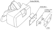
- FIG. 7 is a diagram illustrating a structure in which a three-dimensional information augmentation video seed display device according to an embodiment of the present invention is detachably coupled to a display device.
- FIG. 8 is a flowchart illustrating a step of performing rectification of the 3D information enhancement video seed display method according to an embodiment of the present invention.
- 9A and 9B are diagrams for explaining a breakpoint lookup table utilized in a conventional rectification algorithm.
- FIGS. 10A and 10B are diagrams for explaining a breakpoint lookup table used in performing rectification of a 3D information enhancement video seed display method according to an embodiment of the present invention.
- 11A and 11B are diagrams for explaining current coordinate transformation information utilized in performing rectification of a 3D information enhancement video seed display method according to an embodiment of the present invention.
- FIG. 12 is a diagram for explaining a double target field of current coordinate transformation information used in performing rectification of a 3D information enhancement video seed display method according to an embodiment of the present invention. to be.
- FIG. 13 is a diagram illustrating a differential field of current coordinate transformation information used in performing rectification of the 3D information enhancement video seed display method according to an embodiment of the present invention.
- FIG. 14 is a view illustrating a continuous information field defining a next target coordinate among current coordinate transformation information used in performing rectification of a 3D information enhancement video seed display method according to an embodiment of the present invention. It is a figure shown for description.
- FIG. 1 is a block diagram illustrating a three-dimensional information augmentation video see-through display device according to an embodiment of the present invention.
- a three-dimensional information augmentation video seed display device 100 may include a camera module 110, a camera interface module 120, a rectification module 130, Lens Distortion Compensation Module 140, Image Generation Module 150, Display Module 160, Camera Calibration Module 170, Light Detection Module 180, Microphone Module 185, Space Creation Module 190 , And the controller 195.
- the camera module 110 may include two camera modules for capturing two actual images. That is, the camera module 110 may include a stereoscopic camera for capturing two actual images, which are images corresponding to the right eye and the left eye of the user. Therefore, the two actual images may be divided into left and right images (some regions overlap) on the basis of the photographing target.
- the actual image may mean a captured image of the visible light region photographed by the two camera modules.
- the camera module 110 may include three camera modules. In this case, two camera modules may be used as the stereo camera, and the other camera module may be used to detect a depth of an image.
- the camera module 110 may include an infrared camera module for capturing infrared images.
- Infrared images can be used to enhance the image processing reliability of two real images when the surroundings are dark. That is, the infrared camera module may be driven together with the stereo camera when the surroundings become dark.
- the camera interface module 120 obtains an image from the camera module 110. That is, the camera interface module 120 obtains two actual images from the stereo camera module consisting of two camera modules. In addition, the camera interface module 120 may obtain three real images from three camera modules, or alternatively, two real images and infrared images from a stereo camera module and an infrared camera module.
- the camera interface module 120 may include an interface selection module (see “210" in FIG. 2) and a color space conversion module (see “220" in FIG. 2).
- the interface selection module selects an interface suitable for the camera in consideration of different interfaces for each camera.
- the color space conversion module converts color signals into other colors, such as converting YUV analog video to digital RGB (red, green, blue) video, converting RGB to CMYK (cyan, magenta, yellow, black), and so on. Do it. That is, the color space conversion module converts an image input through the interface selection module into a format for image processing.
- the rectification module 130 performs rectification on two actual images. That is, the rectification module 130 can change the two actual images as if they were taken from a camera arranged on the same column. For example, the rectification module 130 may make the optical axis and the reference point parallel and intersect at infinity. Accordingly, scene overlap can be maximized, and distortion can be minimized.
- the rectification module 130 may extract a reference point from a chess board or a 3D object.
- the rectification module 130 may perform rectification using epipolar geometry. In this way, the reticulation module 130 may provide a high quality image by correcting the error of the instrument (alignment error of two cameras) with software.
- the rectification module 130 may coordinate the same among the plurality of pixels included in each of the at least two real images based on the current reference target break point information on the prestored break point lookup table.
- the coordinates of each pixel group of the current coordinate transformation target may be converted based on the current coordinate transformation information.
- the lens distortion compensation module 140 combines two composite images by combining virtual images with each of the two real images based on a lens distortion compensation value representing a value for compensating for the distortion of the wide-angle lens with respect to the two actual images. Correct the image.
- the lens distortion compensation module 140 is based on a lens distortion compensation value representing a value for compensating for the distortion of the wide-angle lens for the two rectified real image, the virtual image in each of the two actual image You can also correct two composite images combining.
- the spectacle display device such as a head mount display (HMD) uses a wide-angle lens to widen the field of view because the gap between the user's eyes and the lens is narrow. At this time, an image incident through the wide-angle lens is distorted (distorted). This will occur. Therefore, in the present exemplary embodiment, the lens distortion compensation module 140 may apply lens distortion compensation values to two composite images to compensate for distortion of the wide-angle lens by applying opposite distortion to an image incident through the wide-angle lens.
- HMD head mount display
- the virtual image may be input from a computer linked with the three-dimensional information augmentation video see-through display device 100 and combined with each of two real images.
- the virtual image refers to a graphic image for providing a virtual reality (VR) or augmented reality (AV).
- the spectacle display device may have a different lens distortion compensation value for each type or model.
- the HMD of the A product may have a greater distortion of the wide-angle lens than the HMD of the B product. That is, corresponding lens distortion compensation values may be different for each of the plurality of video see-through based display devices. Therefore, in the present embodiment, the lens distortion compensation value matched for each of the plurality of video seed-based display devices may be stored in the lens distortion compensation look-up table.
- the lens distortion compensation module 140 may correct two composite images using the lens distortion compensation lookup table.
- the lens distortion compensation module 140 extracts a lens distortion compensation value matched with the corresponding display device from the lens distortion compensation lookup table, and uses the extracted lens distortion compensation value to have two composite images having opposite distortions. You can correct it.
- the image generation module 150 performs side by side image processing on the two composite images to generate a 3D image for the virtual reality (VR) or the augmented reality (AR). That is, the image generating module 150 may generate a 3D image for virtual reality or augmented reality by performing an image processing operation of converting two composite images divided into left and right into one image having the same size.
- VR virtual reality
- AR augmented reality
- the side-by-side image processing is an algorithm for generating a 3D image and may refer to image processing for setting two images to be arranged left and right, and a detailed description thereof will be omitted.
- the display module 160 displays the generated 3D image on the screen. Accordingly, the user can view the 3D image through the screen.
- the display module 160 may not be included in the three-dimensional information augmented video seed display device 100, and may be implemented as an external display device.
- the camera calibration module 170 may perform camera calibration on the two camera modules based on the infrared image in order to improve image processing reliability on the two actual images.
- the image processing reliability of two real images may be improved through the camera calibration module 170.
- the camera calibration module 170 performs camera calibration for two camera modules, that is, stereo cameras, by using an infrared image captured by the infrared camera module when the surroundings become dark, thereby increasing the sharpness of two actual images.
- the image processing reliability thereof can be improved.
- the light detection module 180 may detect a light position within a predetermined radius based on the current position. In addition, the light detection module 180 may further detect the illuminance of each light for each lighting position. That is, the light detection module 180 may detect the illumination position around the user and the illumination intensity of each illumination position. The sensed illumination position and illuminance can be used to add a shadow effect to the virtual image.
- the microphone module 185 may detect a sound generated within a predetermined radius based on the current position. That is, the microphone module 185 may detect sound generated around the user. In this case, a plurality of microphone modules 185 may be provided. In this case, the plurality of microphone modules 185 may have direct azimuth angles. The detected sound may be transmitted to the other party (a preset sound transmission target, for example, the HMD of the other party in a video conference) through a communication module (not shown).
- a preset sound transmission target for example, the HMD of the other party in a video conference
- the sense of space generation module 190 may generate direction data for each illumination based on the current position based on the detected illumination position. Accordingly, the computer may give a shadow effect (shadow) to the object in the virtual image based on the generated direction data. In addition, the computer may adjust the shadow depth of the object in the virtual image based on the sensed illuminance when applying the shadow effect.
- shadow shadow
- the spatial feeling generating module 190 generates direction data of sound detected by each of the plurality of microphone modules 185 based on the direction of azimuth of each of the plurality of microphone modules 185 when there are a plurality of microphone modules 185. can do.
- the generated direction data may be transmitted to the sound transmission target together with the detected sound.
- the controller 195 is a three-dimensional information augmented video seed display device 100 according to an embodiment of the present invention, that is, a camera module 110, a camera interface module 120, a rectification module 130, Lens Distortion Compensation Module 140, Image Generation Module 150, Display Module 160, Camera Calibration Module 170, Light Detection Module 180, Microphone Module 185, Space Creation Module 190 Etc., the overall operation can be controlled.
- the controller 195 may include at least one of the camera interface module 120, the rectification module 130, the lens distortion compensation module 140, and the image generating module 150. It may be implemented as a hardware chip.
- the 3D information enhancement video seed display device 100 may be combined with a plurality of various display devices.
- the display device may include all of the various video see-through based display devices including the eyeglass display device. Therefore, the 3D information enhancement video seed display device 100 may be detachably coupled to the display device.
- the three-dimensional information augmentation video see-through display device (Stereoscopic Camera Module) 100 is mounted with a mounting base (Mounting base) and a cover (Back), respectively, in a state where the mounting base ( The mounting base may be detachably coupled to various display devices through a method in which the mounting base is detachably attached to the oculus.
- FIG. 2 is a diagram illustrating an operation of a three-dimensional information augmentation video see-through display device according to an embodiment of the present invention.
- the camera interface module 120 selects an interface suitable for two left and right camera modules 110, CAM CON (L) and CAM CON (R), through the interface selection module 210, and a color space.
- the conversion module 220 converts two actual images captured by the CAM CON (L) and the CAM CON (R) into an image processing format.
- the camera interface module 120 selects an interface suitable for one central camera module 110 CAM CON (C) through the interface selection module 210, and selects the CAM CON () through the color space conversion module 220.
- the image captured by C) can be converted into an image processing format.
- the CAM CON (C) may be an infrared camera module for capturing an infrared image
- the camera calibration module 170 may improve image processing reliability of two actual images by performing a camera calibration using the infrared image. .
- the image passed through the camera interface module 120 is input to the rectification module 130, and the rectification module 130 performs rectification on two actual images.
- the rectified image 230 passed through the rectification module 130 is transmitted to the PC 250 (240), the PC 250 generates a virtual image that is a graphic image to be combined with the Rectified Image (230) .
- the Rectified Image 230 is combined with the Rendered Image 260 from the PC 250 and input to the lens distortion compensation module 140.
- an image combining the Rectified Image 230 and the Rendered Image 260 is defined as a composite image. Therefore, two composite images are input to the lens distortion compensation module 140.
- the two composite images are applied to the image generating module 150 after the opposite distortion is applied through the lens distortion compensation module 140 to be corrected to the same or similar to the actual image.
- the two composite images are image-processed in a side by side manner through the image generating module 150 and converted into one 3D image.
- the three-dimensional image is displayed on the screen through the display module (Oculus Lift / HMD Display) 160, so that the user can display the three-dimensional image for virtual reality (VR) or augmented reality (AV) through the screen of the Oculus Lift or HMD. You will be able to see the image.
- VR virtual reality
- AV augmented reality
- the PC 250 may receive the illumination and direction data for each of the surrounding light through the light detection module 180 and the sense of space generation module 190 to give a shadow effect (shadow) to the object in the virtual image, You can also adjust the shadow depth.
- the virtual image 260 to which the shadow effect is applied may be combined with the Rectified Image 230 and input to the lens distortion compensation module 140.
- the PC 250 may receive the surrounding sound through the microphone module 185 and the space generating module 190 and transmit the ambient sound to the counterpart through a network.
- the PC 250 may receive the direction data of the sound detected by each of the plurality of microphone modules 185 through the sense of space generating module 190 and transmit the received direction data to the counterpart through the network.
- the other party can directly hear the sound around the user, and can also feel the liveliness through the direction of the sound.
- FIG. 3 is a PCB block diagram illustrating a connection state between a control unit and a peripheral device of a 3D information enhanced video see-through display device according to an embodiment of the present invention.
- the controller 195 may be implemented as a field programmable gate array (FPGA).
- Three camera modules 110 may be connected to the controller 195, of which two camera modules (Connector (L) and Connector (R)) 310 and 320 are stereo camera modules and the other one camera module.
- IR sensor (C) 330 is an infrared camera module.
- the control unit 195 is connected to two main memories (main memory, for example, DDR3) 340, which are memory for image processing, and booting memory, which is an OS processing memory in which data for initializing the FPGA is stored.
- Main memory for example, DDR3
- booting memory which is an OS processing memory in which data for initializing the FPGA is stored.
- Memory 350 may be connected.
- the boot memory 350 may be implemented as an SD card.
- the controller 195 may be connected to an HDMI 360 that is an input / output interface for transmitting an actual image to the PC 250 or receiving a virtual image from the PC 250.
- the HDMI 360 may also function as an input / output interface for transmitting the 3D image to the Oculus Rift / HMD for displaying the 3D image.
- the HDMI 360 may be replaced by a wireless module that transmits high resolution video and audio in real time at a short range.
- the control unit 195 may be connected to an ADC 170 that performs analog-to-digital conversion of sensing data sensed by the CDS 180 as a light sensing module and the MIC 185 as a microphone module.
- the controller 195 may be connected to the serial communication module 380 for data initialization (input at the time of setting the keyboard, etc.).
- the control unit 195 may be connected to a GPIO (General Purpose Input / Output) 390 and a SOM Cont. 395 as selectable options.
- GPIO General Purpose Input / Output
- 4 to 6 are flowcharts illustrating a three-dimensional information augmentation video seed display method according to an embodiment of the present invention.
- step 410 the 3D information augmentation video see-through display device obtains two actual images from two camera modules.
- the three-dimensional information augmented video see-through display device obtains two real images from two camera modules (510), then obtains an infrared image from an infrared camera module (520), and then processes the two real images.
- camera calibration may be performed for two camera modules based on the infrared image.
- step 420 the 3D information enhancement video seed display device performs rectification on the two real images.
- step 420 a more detailed description of the step 420 will be described later with reference to FIGS. 8 to 14, and overlapping descriptions are omitted.
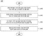
- step 430 the three-dimensional information augmented video see-through display device combines the virtual image to each of the two real images to generate two composite images.
- the three-dimensional information augmented video see-through display device detects the illumination position within a predetermined radius and the illumination of each light based on the current position (610), and then each of the illumination based on the current position based on the detected illumination position After generating the directional data (620), a shadow effect may be applied to the object in the virtual image based on the illumination of each light and the directional data for each light (630). Subsequently, the three-dimensional information augmented video see-through display device may combine the virtual image with the shadow effect to each of the two real images (640).
- the 3D video enhancement video see-through display device corrects the two composite images based on a lens distortion compensation value representing a value for compensating for the distortion of the wide-angle lens for the two actual images.
- the 3D information augmented video see-through display device performs side by side image processing on the two composite images to perform virtual reality (VR) or augmented reality (AR). Create a three-dimensional image.
- VR virtual reality
- AR augmented reality
- step 460 the display device to which the 3D information-separation video see-through display device is detached and displays the generated 3D image.
- FIGS. 8-14 a step 420 of the redirection module 130 and the three-dimensional information augmentation video seed display method of the three-dimensional information augmentation video seed display device 100 will be described.
- FIG. 8 is a flowchart illustrating a step of performing rectification of the 3D information enhancement video seed display method according to an embodiment of the present invention.
- step 420 which is a step of performing rectification on two actual images, is a step of determining a current coordinate transformation target pixel group 810 and a current coordinate transformation, respectively.
- the coordinates of each target pixel group may be converted.
- the rectification module 130 transforms coordinates identical to each other among a plurality of pixels included in each of the at least two real images based on the current reference target break point information on the previously stored break point lookup table. This may mean a step of determining a current coordinate transformation target pixel group including at least one continuous pixel required.
- some of the pixels consecutive to each other in each of the two real images may require the same coordinate transformation.
- the 1st to 3rd pixels may refer to the current coordinate transformation target pixel group, which is a continuous pixel requiring the same coordinate transformation.
- the fourth to eighth pixels may refer to a next coordinate transformation target pixel group that is a continuous pixel requiring the same coordinate transformation.
- break point information information that stores which pixels among consecutive pixels are required to have the same coordinate transformation
- break point information for determining a current coordinate transformation target pixel group may be defined as a break point for the current reference object. Defined as point information.
- a plurality of break point information for distinguishing consecutive pixels requiring the same coordinate transformation among the plurality of pixels included in each of the two actual images may be stored on the break point lookup table.
- 9A and 9B are diagrams for explaining a breakpoint lookup table utilized in a conventional rectification algorithm.
- the conventional break point lookup table may be separately stored for each of the X and Y axis directions.
- the breakpoint information corresponding to the breakpoint information corresponding to each address previously allocated on the internal memory exists. If the corresponding breakpoint information does not exist, the table sets the corresponding address to an empty state.
- break point information is shown in “00000”, “00000”, “01002”, “00001”, “00802”, “00803", “00002”, “01003", “00001” and FIG. 9B shown in FIG. 9A. It may mean “00000”, “00004", "04001”, “04802”, “01803", and "00004" shown.
- the conventional breakpoint lookup table has a problem in that wasted memory occurs when there is no breakpoint information corresponding to a pre-assigned address.
- FIGS. 10A and 10B a breakpoint lookup table used in the step of performing rectification of the 3D information augmentation video seed display method according to an embodiment of the present invention will be described.
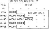
- FIGS. 10A and 10B are diagrams for explaining a breakpoint lookup table used in performing rectification of a 3D information enhancement video seed display method according to an embodiment of the present invention.
- the breakpoint lookup table utilized in performing the redirection of the 3D information augmented video see-through display method according to an embodiment of the present invention is similar to the conventional breakpoint lookup table. It may be stored separately for each of the X-axis direction and Y-axis direction.
- the breakpoint lookup table utilized in the step 420 of the present invention sequentially stores a plurality of breakpoint information in an empty space on an internal memory. As shown in each of the boxes of FIGS. 10A and 10B, it may refer to a table that separately stores storage address information on at least one memory for at least one break point information among the plurality of break point information.
- the breakpoint lookup table utilized in the step 420 of the present invention stores the breakpoint information without wasting memory on the internal memory, thereby effectively utilizing the storage space of the internal memory.
- the conventional break point lookup table is compared with the break point lookup table utilized in step 420 of the present invention.
- the storage address information of "00000” which is the break point information of the m + 5th column of FIG. 9A is "0", and the storage address information of "00000” which is the first breakpoint information of the m + 10th column is "1", m
- the storage address information of "01002”, which is the second breakpoint information of the + 10th column, is "2”, and the storage address information of "00001”, which is the first breakpoint information of the m + 15th column, is "3", m + 15
- the storage address information of "00802", the second break point information of the first column, is "4", the storage address information of "00803", the third break point information of the m + 15th column, is "5", and the storage address information of the m + 20th column is "5".
- the storage address information of the first breakpoint information "00002" is “6"
- the storage address information of "01003" which is the second breakpoint information of the m + 20th column is "7”
- the breakpoint of the m + 25th column is defined as "8”, respectively.
- the storage address information of "00000” which is breakpoint information of the n + 5th column shown in FIG. 9B is "0"
- the storage address information of "00004" which is first breakpoint information of the n + 10th column is "1”. If the storage address information of “00004”, which is the first breakpoint information of the n + 15 th column, is defined as “5”, each breakpoint is used in the breakpoint lookup table utilized in the step 420 of the present invention shown in FIG. 10B. After storing the point information "00000”, “00004", “04001”, “04802”, “01803", and "00004" sequentially, the first break point for each row shown in Fig. 9B. The storage address information "0", "1", and "5" corresponding to the information may be separately stored.
- the pre-stored breakpoint lookup table sequentially stores a plurality of breakpoint information in an empty space in the memory, and stores at least one breakpoint information of at least one breakpoint information among the plurality of sequentially stored breakpoint information. You can save more storage address information.
- step 820 which is a step of transforming coordinates of each pixel group of the current coordinate transformation target, is described.
- the rectification module 130 may convert the current coordinate transformation object based on the current coordinate transformation information including a current difference value that is a difference value between the current coordinate transformation target pixel group and the current target coordinate that is a coordinate to be converted. It may mean a step of converting coordinates of each pixel group.
- step 820 the coordinates of the first pixel included in the current coordinate transformation target pixel group are (1,0), the coordinates of the second pixel are (2,0), and the coordinates of the third pixel are (3 , 0), and the current difference value included in the current coordinate transformation information when the first target coordinate is (1,1), the second pixel is (2,1), and the third pixel is (3,1) May mean as much as +1 in the y-axis direction.
- 11A and 11B are diagrams for explaining current coordinate transformation information utilized in performing rectification of a 3D information enhancement video seed display method according to an embodiment of the present invention.
- the current coordinate conversion information is data composed of 18 bits for each of the X axis direction and the Y axis direction. It is not limited to data.
- the current coordinate transformation information for the X-axis direction includes a double target field including a predetermined number of bits, a differential field including a predetermined number of bits, and It may include a row number field including a predetermined number of bits.
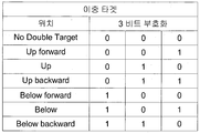
- the dual target field is a field indicating neighboring pixels for interpolating pixel values that are empty when at least two of the pixels included in the current coordinate conversion target pixel group are mapped to the same current target coordinate. It can contain a total of three bits.
- the difference field may mean a field indicating a difference value between a current target coordinate, which is a coordinate to which each of the current coordinate transformation target pixel groups, and a current coordinate transformation target pixel group.
- a differential field which is a field indicating a current difference value, may include at least four bits.
- the difference field includes four bits in total, the difference field is -8 to +7. Since it can be stored, the coordinate transformation of each pixel group of the current coordinate transformation target can be performed in a wider range.
- the horizontal column field is a field for storing coordinate information of pixels included in each pixel group of the current coordinate transformation target, and may include a total of 11 bits.
- the current coordinate transformation information for the Y-axis direction includes a continuous information field including a predetermined number of bits, a differential field including a predetermined number of bits, and It may include a column number field including a preset number of bits.
- the continuous information field may include a next difference value and a current coordinate conversion target pixel, which is a difference value from the next target coordinate, which is a coordinate to be transformed, next to the current coordinate conversion target pixel group.
- the continuous information field may store in advance a value of ⁇ 1, which is a difference between a current difference value of +5 and a next difference value of +4.
- information that the next difference value of the next coordinate conversion target pixel group is less than 1 in the X-axis direction than the current difference value of the current coordinate conversion target pixel group may be stored in advance in the current coordinate conversion information.
- the coordinate transformation of the next coordinate transformation target pixel group can be performed based on the difference value between the current difference value of the current coordinate transformation target pixel group and the next difference value of the next coordinate transformation target pixel group without repeatedly accessing the memory. Since it can be, the operation speed is shortened.
- the current coordinate transformation information is a next difference value that is a difference value with a next target coordinate that is a coordinate to which each of the next coordinate transformation target pixel groups determined in advance is based on the next reference target breakpoint information on the previously stored breakpoint lookup table.
- the difference between the current difference and the current difference can be stored in advance.
- the rectification module 130 may convert the coordinates of each of the next coordinate conversion target pixel groups based on the difference between the next difference value and the current difference value.
- FIG. 12 is a diagram for explaining a double target field of current coordinate transformation information used in performing rectification of a 3D information enhancement video seed display method according to an embodiment of the present invention. to be.
- bit value of 3 bits of the dual target field when the bit value of 3 bits of the dual target field is 0,0,0, this may mean no empty target, and the bit value is 0,0,1. In this case, it may mean that the pixel value of an empty pixel is stored as the pixel value of the Up Forward. If the bit value is 0,1,0, the pixel value of the empty pixel is converted to the pixel value of the Up. If the bit value is 0,1,1, it can mean to save as the pixel value of the upper back. If the bit value is 1,0,0, it is the lower forward. If the bit value is 1,0,1, it means that it is stored as the pixel value of the lower. If the bit value is 1,1,0, it means the lower left. It may mean storing as a pixel value of Backward).
- FIG. 13 is a diagram illustrating a differential field of current coordinate transformation information used in performing rectification of the 3D information enhancement video seed display method according to an embodiment of the present invention.
- the difference field when the difference field includes a total of four bits, the difference field is a difference value between a current target coordinate, which is a coordinate at which the current coordinate transformation target pixel group is to be transformed, and a coordinate of a current coordinate transformation target pixel group.
- the current difference value can be stored in the range of -8 to 7.
- each of the plurality of pixels included in the current coordinate conversion pixel group should be coordinate converted in the X axis direction by -2. Can mean.
- -2 corresponding to 1,0,0,1 may mean a current difference value.
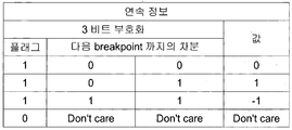
- FIG. 14 is a view illustrating a continuous information field defining a next target coordinate among current coordinate transformation information used in performing rectification of a 3D information enhancement video seed display method according to an embodiment of the present invention. It is a figure shown for description.
- the continuous information field may store in advance a difference value between a current difference value for the current coordinate transformation target pixel group and a next difference value for the next coordinate transformation target pixel group.
- one bit may mean a flag field and the remaining two bits may mean a difference value field.
- the first bit of the difference value field may mean a sign bit and the second bit may mean an absolute value of the difference value.
- the difference between the current difference value and the next difference value may be stored as one of -1, 0, 1, and in this case, the flag field may be set to one value.
- the coordinate conversion of the next coordinate conversion target pixel group can be performed without accessing the memory, and the current difference value and the next difference value If the difference between is less than -1 or greater than 1, the memory must be accessed again to perform coordinate transformation of the next coordinate transformation pixel group.
- the continuous information field includes a total of five bits, a total of three bits remain except for the flag field 1 bit and the sign bit 1 bit, in which case the current information field is presently different.
- the difference between the value and the next difference is 15 in total: -7, -6, -5, -4, -3, -2, -1, 0, 1, 2, 3, 4, 5, 6, 7.
- the difference value can be stored.
- the difference value between the current difference value and the next difference value is in the range of -7 to 7, the coordinate conversion of the next coordinate transformation target pixel group can be performed without accessing the memory. Only when the difference between the difference value and the next difference value is less than or equal to -7 is greater than 7, the memory is accessed again and the coordinate transformation of the next coordinate transformation target pixel group is performed.
- the lens distortion compensation module 140 may compensate for the lens distortion by using the same algorithm as the rectification module 130 described above.
- the lens distortion compensation module 140 is identical to each other among a plurality of pixels included in each of the at least two actualized images based on the current reference lens distortion compensation breakpoint information on the prestored lens distortion compensation lookup table.
- the coordinates of each pixel group of the current coordinate transformation target may be converted based on the current coordinate transformation information.
- the pre-stored lens distortion compensation lookup table sequentially stores the plurality of lens distortion compensation break point information in an empty space on the memory, and compensates at least one lens distortion of the plurality of sequentially stored lens distortion compensation break point information.
- the storage address information on at least one memory for the break point information may be further stored.
- the current coordinate transformation information may be a difference value from a next target coordinate, which is a coordinate to be transformed with each of the next coordinate transformation target pixel groups determined based on the next reference target lens distortion compensation breakpoint information on the previously stored lens distortion compensation lookup table.
- the difference between the next difference and the current difference can be stored in advance.
- the lens distortion compensation module 140 may convert the coordinates of each of the following coordinate conversion target pixel groups based on the difference between the next difference value and the current difference value.
- the rectification apparatus (not shown) according to an embodiment of the present invention is the camera interface module 120 and the rectification module 130 in the three-dimensional information augmented video see-through display device 100 shown in FIG. ) May mean only a device.
- a rectification apparatus may be directed to a camera interface module 120 that acquires at least two actual images from at least two camera modules and to at least two actual images. It may include a repetition module 130 to perform the application (rectification).
- the rectification module 130 requests the same coordinate transformation among the plurality of pixels included in each of the at least two real images based on the current reference target break point information on the previously stored break point lookup table.
- Embodiments of the invention include a computer readable medium containing program instructions for performing various computer-implemented operations.
- the computer readable medium may include program instructions, local data files, local data structures, or the like, alone or in combination.
- the media may be those specially designed and constructed for the purposes of the present invention, or they may be of the kind well-known and available to those having skill in the computer software arts.
- Examples of computer-readable recording media include magnetic media such as hard disks, floppy disks, and magnetic tape, optical recording media such as CD-ROMs, DVDs, magnetic-optical media such as floppy disks, and ROM, RAM, flash memory, and the like.
- Hardware devices specifically configured to store and execute the same program instructions are included.
- Examples of program instructions include not only machine code generated by a compiler, but also high-level language code that can be executed by a computer using an interpreter or the like.
Landscapes
- Engineering & Computer Science (AREA)
- Multimedia (AREA)
- Signal Processing (AREA)
- Computer Graphics (AREA)
- Computer Hardware Design (AREA)
- General Engineering & Computer Science (AREA)
- Software Systems (AREA)
- Physics & Mathematics (AREA)
- General Physics & Mathematics (AREA)
- Theoretical Computer Science (AREA)
- Testing, Inspecting, Measuring Of Stereoscopic Televisions And Televisions (AREA)
- Controls And Circuits For Display Device (AREA)
Abstract
Conformément à un mode de réalisation, la présente invention concerne un appareil destiné à un dispositif d'affichage transparent de vidéo augmentée d'informations tridimensionnelles, qui comprend : un module d'interface de caméra pour obtenir au moins deux images réelles à partir d'au moins deux modules de caméra; un module de rectification pour réaliser une rectification pour lesdites images réelles; un module de compensation de déformation de lentille pour corriger au moins deux images composites dans lesquelles une image virtuelle est combinée auxdites images réelles, sur la base d'une valeur de compensation de déformation de lentille représentant une valeur pour compenser la déformation d'une lentille à grand angle par rapport auxdites images réelles; et un module de génération d'image pour générer une image tridimensionnelle pour une réalité virtuelle (VR) ou une réalité augmentée (AR) par réalisation d'un traitement d'image côte à côte pour lesdites images composites.
Priority Applications (1)
| Application Number | Priority Date | Filing Date | Title |
|---|---|---|---|
| US16/093,860 US10650602B2 (en) | 2016-04-15 | 2017-04-12 | Apparatus and method for three-dimensional information augmented video see-through display, and rectification apparatus |
Applications Claiming Priority (4)
| Application Number | Priority Date | Filing Date | Title |
|---|---|---|---|
| KR20160046176 | 2016-04-15 | ||
| KR10-2016-0046176 | 2016-04-15 | ||
| KR1020170047277A KR101870865B1 (ko) | 2016-04-15 | 2017-04-12 | 삼차원 정보증강 비디오 씨쓰루 디스플레이 장치 및 방법, 렉티피케이션 장치 |
| KR10-2017-0047277 | 2017-04-12 |
Publications (1)
| Publication Number | Publication Date |
|---|---|
| WO2017179912A1 true WO2017179912A1 (fr) | 2017-10-19 |
Family
ID=60041671
Family Applications (1)
| Application Number | Title | Priority Date | Filing Date |
|---|---|---|---|
| PCT/KR2017/003973 WO2017179912A1 (fr) | 2016-04-15 | 2017-04-12 | Appareil et procédé destiné à un dispositif d'affichage transparent de vidéo augmentée d'informations tridimensionnelles, et appareil de rectification |
Country Status (1)
| Country | Link |
|---|---|
| WO (1) | WO2017179912A1 (fr) |
Cited By (2)
| Publication number | Priority date | Publication date | Assignee | Title |
|---|---|---|---|---|
| CN110166760A (zh) * | 2019-05-27 | 2019-08-23 | 浙江开奇科技有限公司 | 基于全景视频影像的影像处理方法及终端设备 |
| CN111556228A (zh) * | 2020-05-15 | 2020-08-18 | 展讯通信(上海)有限公司 | 镜头阴影的校正方法及系统 |
Citations (4)
| Publication number | Priority date | Publication date | Assignee | Title |
|---|---|---|---|---|
| KR20060041060A (ko) * | 2004-11-08 | 2006-05-11 | 한국전자통신연구원 | 다시점 콘텐츠 생성 장치 및 그 방법 |
| US20100260355A1 (en) * | 2006-03-27 | 2010-10-14 | Konami Digital Entertainment Co., Ltd. | Sound Processing Apparatus, Sound Processing Method, Information Recording Medium, and Program |
| US20110234584A1 (en) * | 2010-03-25 | 2011-09-29 | Fujifilm Corporation | Head-mounted display device |
| US20150302648A1 (en) * | 2014-02-18 | 2015-10-22 | Sulon Technologies Inc. | Systems and methods for mapping an environment using structured light |
-
2017
- 2017-04-12 WO PCT/KR2017/003973 patent/WO2017179912A1/fr active Application Filing
Patent Citations (4)
| Publication number | Priority date | Publication date | Assignee | Title |
|---|---|---|---|---|
| KR20060041060A (ko) * | 2004-11-08 | 2006-05-11 | 한국전자통신연구원 | 다시점 콘텐츠 생성 장치 및 그 방법 |
| US20100260355A1 (en) * | 2006-03-27 | 2010-10-14 | Konami Digital Entertainment Co., Ltd. | Sound Processing Apparatus, Sound Processing Method, Information Recording Medium, and Program |
| US20110234584A1 (en) * | 2010-03-25 | 2011-09-29 | Fujifilm Corporation | Head-mounted display device |
| US20150302648A1 (en) * | 2014-02-18 | 2015-10-22 | Sulon Technologies Inc. | Systems and methods for mapping an environment using structured light |
Non-Patent Citations (1)
| Title |
|---|
| HUNG, SON NGUYEN ET AL.: "Real-time Stereo Rectification Using Compressed Look-up Table with Variable Breakpoint Indexing", IECON 2016-42ND ANNUAL CONFERENCE OF THE IEEE INDUSTRIAL ELECTRONICS SOCIETY, 23 October 2016 (2016-10-23), pages 4814 - 4819, XP033033881 * |
Cited By (3)
| Publication number | Priority date | Publication date | Assignee | Title |
|---|---|---|---|---|
| CN110166760A (zh) * | 2019-05-27 | 2019-08-23 | 浙江开奇科技有限公司 | 基于全景视频影像的影像处理方法及终端设备 |
| CN111556228A (zh) * | 2020-05-15 | 2020-08-18 | 展讯通信(上海)有限公司 | 镜头阴影的校正方法及系统 |
| CN111556228B (zh) * | 2020-05-15 | 2022-07-22 | 展讯通信(上海)有限公司 | 镜头阴影的校正方法及系统 |
Similar Documents
| Publication | Publication Date | Title |
|---|---|---|
| KR101870865B1 (ko) | 삼차원 정보증강 비디오 씨쓰루 디스플레이 장치 및 방법, 렉티피케이션 장치 | |
| WO2018052251A1 (fr) | Procédé, appareil et système de partage de région d'affichage de réalité virtuelle | |
| WO2013081429A1 (fr) | Appareil de traitement d'image et procédé d'affichage sous-pixellaire | |
| WO2016190489A1 (fr) | Visiocasque et procédé de commande correspondant | |
| WO2016017966A1 (fr) | Procédé d'affichage d'image par l'intermédiaire d'un dispositif d'affichage monté sur la tête et dispositif d'affichage monté sur la tête pour celui-ci | |
| WO2019059562A1 (fr) | Dispositif électronique comprenant une pluralité de caméras utilisant un mode d'obturateur roulant | |
| WO2017164573A1 (fr) | Appareil d'affichage proche de l'œil et procédé d'affichage proche de l'œil | |
| WO2021133025A1 (fr) | Dispositif électronique comprenant un capteur d'image et son procédé de fonctionnement | |
| WO2020101420A1 (fr) | Procédé et appareil de mesurer des caractéristiques optiques d'un dispositif de réalité augmentée | |
| WO2014178509A1 (fr) | Système multi-projection pour prolonger un élément visuel d'une image principale | |
| WO2018030567A1 (fr) | Hmd et son procédé de commande | |
| WO2011129488A1 (fr) | Caméra stéréoscopique à axe parallèle | |
| WO2019035582A1 (fr) | Appareil d'affichage et serveur, et procédés de commande associés | |
| WO2017026705A1 (fr) | Dispositif électronique pour générer une image tridimensionnelle sur 360 degrés, et procédé associé | |
| WO2017179912A1 (fr) | Appareil et procédé destiné à un dispositif d'affichage transparent de vidéo augmentée d'informations tridimensionnelles, et appareil de rectification | |
| WO2019088407A1 (fr) | Module appareil photo comprenant une matrice de filtres colorés complémentaires et dispositif électronique le comprenant | |
| WO2019160237A1 (fr) | Dispositif électronique, et procédé de commande d'affichage d'images | |
| WO2019164312A1 (fr) | Module de caméra et son procédé de traitement d'image à super-résolution | |
| WO2019059635A1 (fr) | Dispositif électronique pour fournir une fonction en utilisant une image rvb et une image ir acquises par l'intermédiaire d'un capteur d'image | |
| WO2018070793A1 (fr) | Procédé, appareil et support d'enregistrement de traitement d'image | |
| WO2020190030A1 (fr) | Dispositif électronique de génération d'image composite et procédé associé | |
| WO2020145744A1 (fr) | Dispositif de caméra et dispositif électronique le comprenant | |
| WO2017155365A1 (fr) | Appareil électronique de fourniture d'image panoramique et procédé de commande associé | |
| WO2024019599A1 (fr) | Dispositif d'affichage pouvant être porté et servant à améliorer la visibilité d'un objet virtuel | |
| WO2018012925A1 (fr) | Procédé et dispositif de production d'image |
Legal Events
| Date | Code | Title | Description |
|---|---|---|---|
| NENP | Non-entry into the national phase |
Ref country code: DE |
|
| 121 | Ep: the epo has been informed by wipo that ep was designated in this application |
Ref document number: 17782667 Country of ref document: EP Kind code of ref document: A1 |
|
| 122 | Ep: pct application non-entry in european phase |
Ref document number: 17782667 Country of ref document: EP Kind code of ref document: A1 |