WO2017179506A1 - Method for manufacturing fiber reinforced resin material and apparatus for manufacturing fiber reinforced resin material - Google Patents
Method for manufacturing fiber reinforced resin material and apparatus for manufacturing fiber reinforced resin material Download PDFInfo
- Publication number
- WO2017179506A1 WO2017179506A1 PCT/JP2017/014530 JP2017014530W WO2017179506A1 WO 2017179506 A1 WO2017179506 A1 WO 2017179506A1 JP 2017014530 W JP2017014530 W JP 2017014530W WO 2017179506 A1 WO2017179506 A1 WO 2017179506A1
- Authority
- WO
- WIPO (PCT)
- Prior art keywords
- fiber
- fiber bundle
- resin material
- reinforced resin
- sheet
- Prior art date
Links
Images


Classifications
-
- B—PERFORMING OPERATIONS; TRANSPORTING
- B29—WORKING OF PLASTICS; WORKING OF SUBSTANCES IN A PLASTIC STATE IN GENERAL
- B29B—PREPARATION OR PRETREATMENT OF THE MATERIAL TO BE SHAPED; MAKING GRANULES OR PREFORMS; RECOVERY OF PLASTICS OR OTHER CONSTITUENTS OF WASTE MATERIAL CONTAINING PLASTICS
- B29B15/00—Pretreatment of the material to be shaped, not covered by groups B29B7/00 - B29B13/00
- B29B15/08—Pretreatment of the material to be shaped, not covered by groups B29B7/00 - B29B13/00 of reinforcements or fillers
- B29B15/10—Coating or impregnating independently of the moulding or shaping step
- B29B15/12—Coating or impregnating independently of the moulding or shaping step of reinforcements of indefinite length
- B29B15/122—Coating or impregnating independently of the moulding or shaping step of reinforcements of indefinite length with a matrix in liquid form, e.g. as melt, solution or latex
-
- B—PERFORMING OPERATIONS; TRANSPORTING
- B32—LAYERED PRODUCTS
- B32B—LAYERED PRODUCTS, i.e. PRODUCTS BUILT-UP OF STRATA OF FLAT OR NON-FLAT, e.g. CELLULAR OR HONEYCOMB, FORM
- B32B27/00—Layered products comprising a layer of synthetic resin
- B32B27/18—Layered products comprising a layer of synthetic resin characterised by the use of special additives
-
- B—PERFORMING OPERATIONS; TRANSPORTING
- B29—WORKING OF PLASTICS; WORKING OF SUBSTANCES IN A PLASTIC STATE IN GENERAL
- B29B—PREPARATION OR PRETREATMENT OF THE MATERIAL TO BE SHAPED; MAKING GRANULES OR PREFORMS; RECOVERY OF PLASTICS OR OTHER CONSTITUENTS OF WASTE MATERIAL CONTAINING PLASTICS
- B29B11/00—Making preforms
- B29B11/14—Making preforms characterised by structure or composition
- B29B11/16—Making preforms characterised by structure or composition comprising fillers or reinforcement
-
- B—PERFORMING OPERATIONS; TRANSPORTING
- B32—LAYERED PRODUCTS
- B32B—LAYERED PRODUCTS, i.e. PRODUCTS BUILT-UP OF STRATA OF FLAT OR NON-FLAT, e.g. CELLULAR OR HONEYCOMB, FORM
- B32B27/00—Layered products comprising a layer of synthetic resin
- B32B27/06—Layered products comprising a layer of synthetic resin as the main or only constituent of a layer, which is next to another layer of the same or of a different material
- B32B27/08—Layered products comprising a layer of synthetic resin as the main or only constituent of a layer, which is next to another layer of the same or of a different material of synthetic resin
-
- B—PERFORMING OPERATIONS; TRANSPORTING
- B32—LAYERED PRODUCTS
- B32B—LAYERED PRODUCTS, i.e. PRODUCTS BUILT-UP OF STRATA OF FLAT OR NON-FLAT, e.g. CELLULAR OR HONEYCOMB, FORM
- B32B27/00—Layered products comprising a layer of synthetic resin
- B32B27/30—Layered products comprising a layer of synthetic resin comprising vinyl (co)polymers; comprising acrylic (co)polymers
- B32B27/308—Layered products comprising a layer of synthetic resin comprising vinyl (co)polymers; comprising acrylic (co)polymers comprising acrylic (co)polymers
-
- B—PERFORMING OPERATIONS; TRANSPORTING
- B32—LAYERED PRODUCTS
- B32B—LAYERED PRODUCTS, i.e. PRODUCTS BUILT-UP OF STRATA OF FLAT OR NON-FLAT, e.g. CELLULAR OR HONEYCOMB, FORM
- B32B27/00—Layered products comprising a layer of synthetic resin
- B32B27/38—Layered products comprising a layer of synthetic resin comprising epoxy resins
-
- C—CHEMISTRY; METALLURGY
- C08—ORGANIC MACROMOLECULAR COMPOUNDS; THEIR PREPARATION OR CHEMICAL WORKING-UP; COMPOSITIONS BASED THEREON
- C08J—WORKING-UP; GENERAL PROCESSES OF COMPOUNDING; AFTER-TREATMENT NOT COVERED BY SUBCLASSES C08B, C08C, C08F, C08G or C08H
- C08J5/00—Manufacture of articles or shaped materials containing macromolecular substances
- C08J5/04—Reinforcing macromolecular compounds with loose or coherent fibrous material
- C08J5/0405—Reinforcing macromolecular compounds with loose or coherent fibrous material with inorganic fibres
- C08J5/042—Reinforcing macromolecular compounds with loose or coherent fibrous material with inorganic fibres with carbon fibres
-
- D—TEXTILES; PAPER
- D02—YARNS; MECHANICAL FINISHING OF YARNS OR ROPES; WARPING OR BEAMING
- D02J—FINISHING OR DRESSING OF FILAMENTS, YARNS, THREADS, CORDS, ROPES OR THE LIKE
- D02J1/00—Modifying the structure or properties resulting from a particular structure; Modifying, retaining, or restoring the physical form or cross-sectional shape, e.g. by use of dies or squeeze rollers
- D02J1/18—Separating or spreading
-
- D—TEXTILES; PAPER
- D02—YARNS; MECHANICAL FINISHING OF YARNS OR ROPES; WARPING OR BEAMING
- D02J—FINISHING OR DRESSING OF FILAMENTS, YARNS, THREADS, CORDS, ROPES OR THE LIKE
- D02J13/00—Heating or cooling the yarn, thread, cord, rope, or the like, not specific to any one of the processes provided for in this subclass
-
- D—TEXTILES; PAPER
- D06—TREATMENT OF TEXTILES OR THE LIKE; LAUNDERING; FLEXIBLE MATERIALS NOT OTHERWISE PROVIDED FOR
- D06H—MARKING, INSPECTING, SEAMING OR SEVERING TEXTILE MATERIALS
- D06H7/00—Apparatus or processes for cutting, or otherwise severing, specially adapted for the cutting, or otherwise severing, of textile materials
- D06H7/02—Apparatus or processes for cutting, or otherwise severing, specially adapted for the cutting, or otherwise severing, of textile materials transversely
-
- B—PERFORMING OPERATIONS; TRANSPORTING
- B29—WORKING OF PLASTICS; WORKING OF SUBSTANCES IN A PLASTIC STATE IN GENERAL
- B29K—INDEXING SCHEME ASSOCIATED WITH SUBCLASSES B29B, B29C OR B29D, RELATING TO MOULDING MATERIALS OR TO MATERIALS FOR MOULDS, REINFORCEMENTS, FILLERS OR PREFORMED PARTS, e.g. INSERTS
- B29K2101/00—Use of unspecified macromolecular compounds as moulding material
- B29K2101/10—Thermosetting resins
-
- B—PERFORMING OPERATIONS; TRANSPORTING
- B32—LAYERED PRODUCTS
- B32B—LAYERED PRODUCTS, i.e. PRODUCTS BUILT-UP OF STRATA OF FLAT OR NON-FLAT, e.g. CELLULAR OR HONEYCOMB, FORM
- B32B2250/00—Layers arrangement
- B32B2250/02—2 layers
-
- B—PERFORMING OPERATIONS; TRANSPORTING
- B32—LAYERED PRODUCTS
- B32B—LAYERED PRODUCTS, i.e. PRODUCTS BUILT-UP OF STRATA OF FLAT OR NON-FLAT, e.g. CELLULAR OR HONEYCOMB, FORM
- B32B2250/00—Layers arrangement
- B32B2250/24—All layers being polymeric
-
- B—PERFORMING OPERATIONS; TRANSPORTING
- B32—LAYERED PRODUCTS
- B32B—LAYERED PRODUCTS, i.e. PRODUCTS BUILT-UP OF STRATA OF FLAT OR NON-FLAT, e.g. CELLULAR OR HONEYCOMB, FORM
- B32B2262/00—Composition or structural features of fibres which form a fibrous or filamentary layer or are present as additives
- B32B2262/10—Inorganic fibres
- B32B2262/106—Carbon fibres, e.g. graphite fibres
-
- B—PERFORMING OPERATIONS; TRANSPORTING
- B32—LAYERED PRODUCTS
- B32B—LAYERED PRODUCTS, i.e. PRODUCTS BUILT-UP OF STRATA OF FLAT OR NON-FLAT, e.g. CELLULAR OR HONEYCOMB, FORM
- B32B2305/00—Condition, form or state of the layers or laminate
- B32B2305/07—Parts immersed or impregnated in a matrix
- B32B2305/076—Prepregs
-
- B—PERFORMING OPERATIONS; TRANSPORTING
- B32—LAYERED PRODUCTS
- B32B—LAYERED PRODUCTS, i.e. PRODUCTS BUILT-UP OF STRATA OF FLAT OR NON-FLAT, e.g. CELLULAR OR HONEYCOMB, FORM
- B32B2305/00—Condition, form or state of the layers or laminate
- B32B2305/22—Fibres of short length
-
- B—PERFORMING OPERATIONS; TRANSPORTING
- B32—LAYERED PRODUCTS
- B32B—LAYERED PRODUCTS, i.e. PRODUCTS BUILT-UP OF STRATA OF FLAT OR NON-FLAT, e.g. CELLULAR OR HONEYCOMB, FORM
- B32B2363/00—Epoxy resins
-
- B—PERFORMING OPERATIONS; TRANSPORTING
- B32—LAYERED PRODUCTS
- B32B—LAYERED PRODUCTS, i.e. PRODUCTS BUILT-UP OF STRATA OF FLAT OR NON-FLAT, e.g. CELLULAR OR HONEYCOMB, FORM
- B32B37/00—Methods or apparatus for laminating, e.g. by curing or by ultrasonic bonding
- B32B37/10—Methods or apparatus for laminating, e.g. by curing or by ultrasonic bonding characterised by the pressing technique, e.g. using action of vacuum or fluid pressure
- B32B37/1027—Pressing using at least one press band
-
- B—PERFORMING OPERATIONS; TRANSPORTING
- B32—LAYERED PRODUCTS
- B32B—LAYERED PRODUCTS, i.e. PRODUCTS BUILT-UP OF STRATA OF FLAT OR NON-FLAT, e.g. CELLULAR OR HONEYCOMB, FORM
- B32B37/00—Methods or apparatus for laminating, e.g. by curing or by ultrasonic bonding
- B32B37/14—Methods or apparatus for laminating, e.g. by curing or by ultrasonic bonding characterised by the properties of the layers
- B32B37/16—Methods or apparatus for laminating, e.g. by curing or by ultrasonic bonding characterised by the properties of the layers with all layers existing as coherent layers before laminating
- B32B37/20—Methods or apparatus for laminating, e.g. by curing or by ultrasonic bonding characterised by the properties of the layers with all layers existing as coherent layers before laminating involving the assembly of continuous webs only
- B32B37/203—One or more of the layers being plastic
-
- B—PERFORMING OPERATIONS; TRANSPORTING
- B32—LAYERED PRODUCTS
- B32B—LAYERED PRODUCTS, i.e. PRODUCTS BUILT-UP OF STRATA OF FLAT OR NON-FLAT, e.g. CELLULAR OR HONEYCOMB, FORM
- B32B38/00—Ancillary operations in connection with laminating processes
- B32B38/0004—Cutting, tearing or severing, e.g. bursting; Cutter details
-
- B—PERFORMING OPERATIONS; TRANSPORTING
- B32—LAYERED PRODUCTS
- B32B—LAYERED PRODUCTS, i.e. PRODUCTS BUILT-UP OF STRATA OF FLAT OR NON-FLAT, e.g. CELLULAR OR HONEYCOMB, FORM
- B32B38/00—Ancillary operations in connection with laminating processes
- B32B38/08—Impregnating
-
- B—PERFORMING OPERATIONS; TRANSPORTING
- B65—CONVEYING; PACKING; STORING; HANDLING THIN OR FILAMENTARY MATERIAL
- B65H—HANDLING THIN OR FILAMENTARY MATERIAL, e.g. SHEETS, WEBS, CABLES
- B65H2701/00—Handled material; Storage means
- B65H2701/30—Handled filamentary material
- B65H2701/31—Textiles threads or artificial strands of filaments
- B65H2701/312—Fibreglass strands
-
- B—PERFORMING OPERATIONS; TRANSPORTING
- B65—CONVEYING; PACKING; STORING; HANDLING THIN OR FILAMENTARY MATERIAL
- B65H—HANDLING THIN OR FILAMENTARY MATERIAL, e.g. SHEETS, WEBS, CABLES
- B65H2701/00—Handled material; Storage means
- B65H2701/30—Handled filamentary material
- B65H2701/31—Textiles threads or artificial strands of filaments
- B65H2701/314—Carbon fibres
-
- B—PERFORMING OPERATIONS; TRANSPORTING
- B65—CONVEYING; PACKING; STORING; HANDLING THIN OR FILAMENTARY MATERIAL
- B65H—HANDLING THIN OR FILAMENTARY MATERIAL, e.g. SHEETS, WEBS, CABLES
- B65H51/00—Forwarding filamentary material
- B65H51/005—Separating a bundle of forwarding filamentary materials into a plurality of groups
-
- B—PERFORMING OPERATIONS; TRANSPORTING
- B65—CONVEYING; PACKING; STORING; HANDLING THIN OR FILAMENTARY MATERIAL
- B65H—HANDLING THIN OR FILAMENTARY MATERIAL, e.g. SHEETS, WEBS, CABLES
- B65H51/00—Forwarding filamentary material
- B65H51/02—Rotary devices, e.g. with helical forwarding surfaces
- B65H51/04—Rollers, pulleys, capstans, or intermeshing rotary elements
- B65H51/08—Rollers, pulleys, capstans, or intermeshing rotary elements arranged to operate in groups or in co-operation with other elements
- B65H51/10—Rollers, pulleys, capstans, or intermeshing rotary elements arranged to operate in groups or in co-operation with other elements with opposed coacting surfaces, e.g. providing nips
- B65H51/105—Rollers, pulleys, capstans, or intermeshing rotary elements arranged to operate in groups or in co-operation with other elements with opposed coacting surfaces, e.g. providing nips one of which is an endless belt
-
- C—CHEMISTRY; METALLURGY
- C08—ORGANIC MACROMOLECULAR COMPOUNDS; THEIR PREPARATION OR CHEMICAL WORKING-UP; COMPOSITIONS BASED THEREON
- C08J—WORKING-UP; GENERAL PROCESSES OF COMPOUNDING; AFTER-TREATMENT NOT COVERED BY SUBCLASSES C08B, C08C, C08F, C08G or C08H
- C08J2363/00—Characterised by the use of epoxy resins; Derivatives of epoxy resins
- C08J2363/10—Epoxy resins modified by unsaturated compounds
-
- D—TEXTILES; PAPER
- D10—INDEXING SCHEME ASSOCIATED WITH SUBLASSES OF SECTION D, RELATING TO TEXTILES
- D10B—INDEXING SCHEME ASSOCIATED WITH SUBLASSES OF SECTION D, RELATING TO TEXTILES
- D10B2101/00—Inorganic fibres
- D10B2101/10—Inorganic fibres based on non-oxides other than metals
- D10B2101/12—Carbon; Pitch
-
- D—TEXTILES; PAPER
- D10—INDEXING SCHEME ASSOCIATED WITH SUBLASSES OF SECTION D, RELATING TO TEXTILES
- D10B—INDEXING SCHEME ASSOCIATED WITH SUBLASSES OF SECTION D, RELATING TO TEXTILES
- D10B2505/00—Industrial
- D10B2505/02—Reinforcing materials; Prepregs
Definitions
- the present invention relates to a method for manufacturing a fiber reinforced resin material and a device for manufacturing a fiber reinforced resin material.
- the present application claims priority based on Japanese Patent Application No. 2016-078938 filed in Japan on April 11, 2016 and Japanese Patent Application No. 2016-120017 filed on June 16, 2016 in Japan. These contents are incorporated herein by reference.
- SMC Sheet Molding Compound
- SMC Sheet Molding Compound
- SMC is a sheet fiber bundle group formed of a plurality of fiber bundles obtained by cutting long reinforcing fibers such as glass fibers and carbon fibers into a predetermined length. It is a fiber reinforced resin material impregnated with a thermosetting resin.
- SMC is used as an intermediate material for obtaining a molded product, and has a property of easily flowing during molding with a mold. Therefore, SMC is suitably used when forming parts with different thicknesses, ribs, bosses, etc. in the molded product.
- SMC fiber reinforced resin material
- a fiber bundle with a large number of filaments called a large tow is often used for the purpose of reducing the production cost.
- the opened fiber bundle is divided into a plurality of fiber bundles, and the divided fiber bundle is cut (for example, patent References 1, 2).
- the fiber bundle after opening is cut to form a sheet-like fiber bundle group, and the sheet-like fiber bundle group is impregnated with a resin to obtain a fiber-reinforced resin material (SMC).
- SMC fiber-reinforced resin material
- a resin-rich portion is generated in the fiber reinforced resin material, and sufficient strength may not be obtained.
- the present invention provides a method for producing a fiber reinforced resin material and an apparatus for producing a fiber reinforced resin material, in which generation of a resin-rich portion in the fiber reinforced resin material is suppressed and a fiber reinforced resin material having sufficient strength is obtained.
- the purpose is to provide.
- the present invention provides a method for producing a fiber reinforced resin material and an apparatus for producing a fiber reinforced resin material having the following configuration.
- a fiber-opening step in which a long fiber bundle is widened in the width direction by opening, and is made flat.
- a method for producing a fiber-reinforced resin material comprising a heat setting step of heating a fiber bundle after opening and heat-setting in a flat state.
- the fiber bundle after heat setting is continuously cut, and the plurality of cut fiber bundles are spread in a sheet form on the first resin sheet in which the resin is made into a sheet form.
- the apparatus for producing a fiber-reinforced resin material according to [7] or [8], comprising a cutting machine that forms a sheet-like fiber bundle group. [10] After the cutting machine, the sheet-like fiber bundle group is bonded with a second resin sheet in the form of a sheet and pressed, and the sheet-like fiber bundle group is impregnated with the resin to reinforce the fiber.
- a fiber-reinforced resin material is obtained by the following bending test.
- Bending test A test piece having a length of 150 mm is cut out from the fiber bundle to be cut, and a portion from the first end in the length direction to the second end of the test piece is placed on a plane.
- a portion 100 mm from the first end of the test piece is in a free state, and the distance between the lower end of the first end and the plane in that state is defined as a deflection amount H (mm).
- H deflection amount
- the occurrence of a resin-rich portion in the fiber-reinforced resin material is suppressed, and a fiber-reinforced resin material having sufficient strength can be obtained. If the manufacturing apparatus of a fiber reinforced resin material is used, generation
- the method for producing a fiber reinforced resin material of the present invention is a sheet-like fiber bundle group formed by continuously cutting a long fiber bundle that has been heat-set in a flat state after opening and forming a plurality of cut fiber bundles.
- a fiber reinforced resin material (SMC) by impregnating a resin, a fiber bundle having a bending amount H measured by a bending test described later of less than 15 mm is cut.
- the fiber-reinforced resin material manufacturing apparatus 100 (hereinafter simply referred to as “manufacturing apparatus 100”) of the present embodiment includes a fiber opening unit 50, a fiber separation unit 52, and a heat setting unit 54, as shown in FIG.
- the second coating unit 15 and the impregnation unit 16 are provided.
- the opening part 50 is a part that widens the long fiber bundle f1 drawn out from the bobbin B1 in the width direction (Y direction) by opening and makes it flat.
- the opening part 50 includes a plurality of opening bars 17 provided side by side in the X-axis direction with a space therebetween.
- the fiber bundle f ⁇ b> 1 passes through the upper and lower sides of each spread bar 17 in a zigzag manner.
- the fiber bundle f ⁇ b> 1 is widened in the width direction by means such as heating, rubbing, and swinging by the respective spread bars 17.
- a flat fiber bundle f2 is obtained.
- the splitting part 52 is a part that divides the fiber bundle after opening in the width direction (Y direction) by splitting.
- the splitting unit 52 is arranged at the subsequent stage of the opening unit 50 and includes a plurality of rotary blades 18.
- the plurality of rotary blades 18 are arranged side by side at a predetermined interval in the width direction (Y-axis direction) of the opened fiber bundle f2.
- Each rotary blade 18 is provided with a plurality of blades 18a arranged in a row in the circumferential direction.
- the plurality of blades 18a are intermittently stuck into the fiber bundle f2, and the fiber bundle f2 is divided in the width direction to become a plurality of fiber bundles f3.
- the plurality of separated fiber bundles f3 may be in a completely separated state, or may be partially unseparated (combined state).
- the heat setting part 54 is a part which heats the fiber bundle after opening and heat-sets it in a flat state.
- the heat setting unit 54 is arranged at the subsequent stage of the separating unit 52.
- the splitting part 52 is arranged between the opening part 50 and the heat setting part 54, the fiber bundle f3 that has been opened and further split is heated by the heat setting part 54 to be flat.
- the heat is set in the state.
- the heat setting unit 54 includes a plurality of guide rolls 55, a heating unit 56, and a plurality of godet rolls 19.
- the fiber bundle f3 split in the splitting unit 52 is conveyed in the X direction by a plurality of guide rolls 55, heated by the heating means 56, and set in a flat state. Yes. Further, the fiber bundle f ⁇ b> 3 after heat setting is guided to the cutting machine 13 by a plurality of godet rolls 19. When the fiber bundle f3 is heat-set by the heat setting unit 54, the fiber bundle f3 is maintained in a flat state until a subsequent process.
- the first carrier sheet supply unit 11 supplies the long first carrier sheet C1 drawn from the first raw roll R1 to the first transport unit 20.
- the 1st conveyance part 20 is provided with the conveyor 23 which multiplied the endless belt 22 between a pair of pulleys 21a and 21b.
- the endless belt 22 is circulated by rotating the pair of pulleys 21a and 21b in the same direction, and the first carrier sheet C1 is conveyed toward the right side in the X-axis direction on the surface of the endless belt 22.
- the first coating unit 12 is located immediately above the pulley 21a side in the first transport unit 20, and includes a coater 24 that supplies a paste P containing resin. As the first carrier sheet C1 passes through the coater 24, the paste P is applied with a predetermined thickness on the surface of the first carrier sheet C1 to form the first resin sheet S1. The first resin sheet S1 travels along with the conveyance of the first carrier sheet C1.
- the cutting machine 13 is located above the first carrier sheet C1 at a later stage in the transport direction than the first coating unit 12.
- the cutting machine 13 continuously cuts the fiber bundle f3 after heat setting guided by a plurality of godet rolls 19 to a predetermined length.
- the cutting machine 13 includes a guide roll 25, a pinch roll 26, and a cutter roll 27. I have.
- the guide roll 25 guides the supplied fiber bundle f3 downward while rotating.
- the pinch roll 26 rotates in the opposite direction to the guide roll 25 while sandwiching the fiber bundle f3 with the guide roll 25. Thereby, the fiber bundle f1 is pulled out from the bobbin B1.
- the cutter roll 27 cuts the fiber bundle f3 so as to have a predetermined length while rotating.
- the fiber bundle f4 cut to a predetermined length by the cutter 13 is dropped and dispersed on the first resin sheet S1, and the sheet-like fiber bundle group F is formed.
- the second carrier sheet supply unit 14 supplies the long second carrier sheet C2 drawn from the second raw fabric roll R2 to the second transport unit 28.
- the second transport unit 28 is located above the first carrier sheet C ⁇ b> 1 transported by the conveyor 23 and includes a plurality of guide rolls 29.
- the second transport unit 28 transports the second carrier sheet C2 supplied from the second carrier sheet supply unit 14 in the direction opposite to the first carrier sheet C1 (left side in the X-axis direction).
- the conveying direction is reversed by the plurality of guide rolls 29 in the same direction as the first carrier sheet C1.
- the second coating unit 15 includes a coater 30 that is located immediately above the second carrier sheet C2 that is conveyed in the direction opposite to the first carrier sheet C1 and that supplies a paste P containing resin. .
- a coater 30 that is located immediately above the second carrier sheet C2 that is conveyed in the direction opposite to the first carrier sheet C1 and that supplies a paste P containing resin. .
- the paste P is applied with a predetermined thickness on the surface of the second carrier sheet C2, and the second resin sheet S2 is formed.
- the second resin sheet S2 travels with the conveyance of the second carrier sheet C2.
- the impregnation portion 16 is a portion that is bonded to the sheet-like fiber bundle group F with the second resin sheet S2 and pressurized, and impregnated with resin in the sheet-like fiber bundle group F to form a fiber-reinforced resin material.
- the impregnation unit 16 is located at a later stage than the cutting machine 13 in the first transport unit 20 and includes a bonding mechanism 31 and a pressure mechanism 32.
- the bonding mechanism 31 is located above the pulley 21 b of the conveyor 23 and includes a plurality of bonding rolls 33.
- the some bonding roll 33 is arrange
- the first carrier sheet C1 and the second carrier sheet C2 are overlapped with the first resin sheet S1, the sheet-like fiber bundle group F, and the second resin sheet S2 being sandwiched therebetween. Be transported.
- what bonded the 1st carrier sheet C1 and the 2nd carrier sheet C2 in the state where the 1st resin sheet S1, sheet-like fiber bundle group F, and the 2nd resin sheet S2 were inserted was pasted sheet S3. That's it.
- the pressurizing mechanism 32 is located at the subsequent stage of the bonding mechanism 31 and has an endless belt 35b between a pair of pulleys 34a and 34d and a lower conveyor 36A in which the endless belt 35a is multiplied between the pair of pulleys 34a and 34b. And an upper conveyor 36B.
- the lower conveyor 36A and the upper conveyor 36B are arranged to face each other in a state where the endless belts 35a and 35b are abutted with each other.
- the pair of pulleys 34a and 34b of the lower conveyor 36A are rotated in the same direction, whereby the endless belt 35a is circulated. Further, in the pressurizing mechanism 32, the pair of pulleys 34c and 34d of the upper conveyor 36B are rotated in the same direction, whereby the endless belt 35b is rotated in the reverse direction at the same speed as the endless belt 35a. Thereby, bonding sheet
- the pressurizing mechanism 32 is further provided with a plurality of lower rolls 37a and a plurality of upper rolls 37b.
- the plurality of lower rolls 37a are arranged side by side in the transport direction in contact with the back surface of the butted portion of the endless belt 35a.
- the plurality of upper rolls 37b are arranged side by side in the transport direction in contact with the back surface of the butted portion of the endless belt 35b.
- the some lower side roll 37a and the some upper side roll 37b are arrange
- the pressurizing mechanism 32 the first resin sheet S1 sandwiched between the first carrier sheet C1 and the second carrier sheet C2 while the bonding sheet S3 passes between the endless belts 35a and 35b.
- the sheet-like fiber bundle group F and the second resin sheet S2 are pressed by a plurality of lower rolls 37a and a plurality of upper rolls 37b.
- the sheet-like fiber bundle group F is impregnated with the resin of the first resin sheet S1 and the second resin sheet S2.
- the raw fabric R of the fiber reinforced resin material (SMC) is obtained.
- the original fabric R can be cut into a predetermined length and used for molding.
- the 1st carrier sheet C1 and the 2nd carrier sheet C2 are peeled from SMC before shaping
- the manufacturing apparatus 100 includes the heat setting unit 54 that heats and sets the fiber bundle after opening and splitting in a flat state.
- the fiber bundle after opening and splitting is heat-set in a flat state by the heat setting unit 54, thereby cutting the fiber bundle to form a sheet-like fiber bundle group as compared with the case where heat setting is not performed.
- the flatness of the fiber bundle is maintained and the fiber bundle is not folded, and the gap formed between the fiber bundles is further reduced.
- a fiber reinforced resin material having sufficient strength can be obtained.
- the manufacturing method of the fiber reinforced resin material using the manufacturing apparatus 100 has the following opening process, a parting process, a heat setting process, a spreading process, and a bonding impregnation process.
- Opening step A step of widening a long fiber bundle in the width direction by opening to make it flat.
- Splitting step A step of dividing the fiber bundle after opening in the width direction by splitting.
- Heat setting step A step of heating and setting the fiber bundle after opening and splitting in a flat state.
- Spreading step Continuously cutting the fiber bundle after heat setting, and spraying a plurality of cut fiber bundles into a sheet form on the first resin sheet in which the resin is made into a sheet form to form a sheet-like fiber bundle group Process.
- Bonding impregnation step a second resin sheet in which a resin is formed into a sheet shape is bonded and pressed onto the sheet-like fiber bundle group, and a fiber-reinforced resin material is obtained by impregnating the sheet-like fiber bundle group with the resin. Combined impregnation process.
- a long fiber bundle f1 is pulled out from the bobbin B1, and the fiber bundle f1 is passed in a zigzag manner in the top and bottom of each fiber opening bar 17 in the fiber opening portion 50, and is spread in the width direction by fiber opening and is flat. Let it be bundle f2.
- a carbon fiber bundle is preferable.
- a glass fiber bundle may be used as the fiber bundle.
- the fiber bundle is not particularly limited. For example, a fiber bundle having 3,000 or more fibers can be used, and a fiber bundle having 12,000 or more fibers can also be preferably used.
- the fiber bundle is usually provided with a sizing agent for the purpose of improving the convergence of each fiber. It does not specifically limit as a sizing agent, A well-known sizing agent can be used.
- the fiber bundle f2 is allowed to pass while rotating the plurality of rotary blades 18, the plurality of blades 18a are pierced intermittently, and the fiber bundle f2 is divided in the width direction to form a plurality of fiber bundles f3.
- the fiber bundle f3 after the opening and splitting is heated by the heating means 56 while being conveyed in the X direction by the plurality of guide rolls 55, and is heat-set in a flat state.
- the fiber bundle f ⁇ b> 3 after heat setting is guided to the cutting machine 13 by a plurality of godet rolls 19.
- the tow form is usually retained by the sizing agent, but the fibers bound by the sizing agent are partially separated in the above opening process. Since the convergence property of the tow is lowered, the shape retention of the fiber bundles f2 and f3 is lowered.
- the sizing agent applied to the fiber bundle melts and solidifies in a state in which the fibers are bound again. Therefore, the shape retention of the fiber bundles f2 and f3 Is recovered, the rigidity of the fiber bundle after opening is increased, and it becomes difficult to be folded or bent.
- heating temperature in a heat setting according to the kind of sizing agent so that the sizing agent provided to the fiber bundle may melt
- heating temperature is more than a lower limit, the effect of a heat setting will be easy to be acquired. If the heating temperature is not more than the upper limit value, volatilization of the sizing agent tends to be suppressed, so that the effect of heat setting is easily obtained.
- the effect of a heat setting can be acquired by heating a fiber bundle and melting a sizing agent so that the viscosity of the sizing agent adhering to a fiber bundle may be 1.5 Pa.s or less.
- the heating time in the heat setting may be set as appropriate so that the sizing agent applied to the fiber bundle is melted, preferably 1 to 15 seconds, and more preferably 5 to 15 seconds.
- the first carrier sheet supply unit 11 pulls out the long first carrier sheet C1 from the first raw fabric roll R1 and supplies it to the first transport unit 20, and the first coating unit 12 pastes the paste. P is applied with a predetermined thickness to form the first resin sheet S1. By transporting the first carrier sheet C1 by the first transport unit 20, the first resin sheet S1 on the first carrier sheet C1 is caused to travel.
- thermosetting resin As the resin contained in the paste P, a thermosetting resin is preferable. It does not specifically limit as a thermosetting resin, For example, unsaturated polyester resin etc. are mentioned.
- the paste P may contain a filler such as calcium carbonate, a low shrinkage agent, a release agent, a curing initiator, a thickener, and the like.
- the fiber bundle f3 guided by the plurality of godet rolls 19 is continuously cut into a predetermined length by the cutting machine 13, and the cut fiber bundle f4 is dropped onto the first resin sheet S1 and dispersed. .
- the sheet-like fiber bundle group F in which the fiber bundles f4 are dispersed in a random fiber orientation is continuously formed on the traveling first resin sheet S1.
- the cutting machine 13 cuts the fiber bundle f3 having a bending amount H measured by the following bending test of less than 15 mm. When the bending amount H of the fiber bundle f3 is less than 15 mm, the flatness of the cut fiber bundle f4 is easily maintained, and the spread fiber bundle f4 is not easily folded.
- a test piece 600 having a length of 150 mm is cut out from the fiber bundle f3 to be cut, and a portion from a first end 600a in the length direction to a second end 600b from a position PI of 100 mm from the first end 600a in the length direction of the test piece 600 is obtained.
- the part of 100 mm from the 1st end 600a in the test piece 600 is made into a free state. Since a portion of 100 mm from the first end 600a of the test piece 600 is bent and droops, the distance between the lower end of the first end 600a and the plane 400 in that state is defined as a bending amount H (mm).
- the deflection amount H measured by the deflection test of the fiber bundle to be cut is less than 15 mm, preferably 0 to 14 mm, more preferably 5 to 13 mm. If the bending amount H is equal to or greater than the lower limit value, a fiber reinforced resin material having high strength can be obtained more. As the deflection amount H is smaller, the fiber bundle after cutting that is spread when forming the sheet-like fiber bundle group is less likely to be folded, and a fiber-reinforced resin material having high strength is more easily obtained.
- the bending amount H of the fiber bundle to be cut can be adjusted by adjusting the type of sizing agent used in the fiber bundle, the fiber opening condition, and the heat setting condition. Specifically, use a sizing agent with a higher binding strength, increase the thickness of the fiber bundle after opening, or increase the heating temperature of the heat set to melt the sizing agent sufficiently, The amount of flexure H is reduced by reattaching.
- the second carrier sheet supply unit 14 pulls out the long second carrier sheet C2 from the second raw fabric roll R2 and supplies it to the second transport unit 28.
- the second coating unit 15 applies the paste P with a predetermined thickness on the surface of the second carrier sheet C2 to form the second resin sheet S2.
- the second resin sheet S2 is caused to travel by conveying the second carrier sheet C2, and the second resin sheet S2 is bonded onto the sheet-like fiber bundle group F by the bonding mechanism 31 in the impregnation unit 16. Then, the first resin sheet S1, the sheet-like fiber bundle group F, and the second resin sheet S2 are pressurized by the pressurizing mechanism 32, and the resin of the first resin sheet S1 and the second resin sheet S2 is applied to the sheet-like fiber bundle group F. Impregnate. Thereby, the raw fabric R in which the fiber reinforced resin material is sandwiched between the first carrier sheet C1 and the second carrier sheet C2 is obtained.
- the fiber bundle after opening and splitting is heated and heat-set in a flat state.
- the fiber bundle after opening and splitting is heat-set in a flat state
- the fiber bundle is easily maintained in a flat state as compared with a case where heat setting is not performed.
- a fiber bundle having a deflection amount H of less than 15 mm is cut to form a sheet-like fiber bundle group, and the sheet-like fiber bundle group is impregnated with a resin to produce fibers.
- the flat state is maintained and the folding is less, and between the fiber bundles.
- the gap which can be made can be made smaller. Thereby, since it is suppressed that a resin rich part is formed in the fiber reinforced resin material obtained by impregnating the resin, a fiber reinforced resin material having sufficient strength can be obtained.
- the manufacturing apparatus of the reinforcing fiber resin material and the manufacturing method of the reinforcing fiber resin material of the present invention are not limited to the manufacturing apparatus 100 and the method using the manufacturing apparatus 100 described above.
- the fiber bundle after the fiber opening, splitting, and heat setting is guided to the cutting machine by the godet roll, but the fiber bundle after the fiber opening is guided by the godet roll to split the fiber.
- heat setting may be performed.
- the mode in which the fiber bundle after the spread is guided by the godet roll is used to separate the fiber bundle, even if the fiber bundle is fluffed at the time of the fiber split, compared to the mode in which the fiber bundle after the spread is split and guided by the godet roll. This is advantageous in that problems due to winding around the roll are less likely to occur.
- the reinforcing fiber resin material manufacturing apparatus of the present invention may be, for example, the reinforcing fiber resin material manufacturing apparatus 200 illustrated in FIG. 3 (hereinafter simply referred to as “manufacturing apparatus 200”). .
- the manufacturing apparatus 200 is the same as the manufacturing apparatus 100 except that it includes a splitting part 52A and a heat setting part 54A instead of the splitting part 52 and the heat setting part 54.
- the splitting unit 52A is the same as the splitting unit 52 except that a plurality of godet rolls 19 are provided in front of the rotary blade 18.
- the heat setting unit 54A is the same as the heat setting unit 54 except that the plurality of godet rolls 19 are not provided in the subsequent stage.
- the fiber bundle f1 drawn out from the bobbin B1 is opened by the opening part 50, and the opened fiber bundle f2 is guided to the rotary blade 18 by the plurality of godet rolls 19 in the dividing part 52A.
- the split fiber bundle f3 is heat set by the heat setting unit 54A and supplied to the cutting machine 13.
- the aspect of the manufacturing apparatus 200 is the aspect of the manufacturing apparatus 100 except that the positions of the plurality of godet rolls 19 are changed between the heating means 56 and the cutting machine 13 and between the opening portion 50 and the rotary blade 18. Is the same.
- the manufacturing apparatus 200 of the present embodiment also includes a heat setting portion 54A that heats and sets a fiber bundle after opening and splitting in a flat state.
- the fiber bundle after opening and splitting is heat-set in a flat state by the heat setting portion 54A, thereby cutting the fiber bundle to form a sheet-like fiber bundle group as compared with the case where heat setting is not performed.
- the gap formed between the fiber bundles becomes smaller. Thereby, since it is suppressed that a resin rich part is formed in the fiber reinforced resin material obtained by impregnating the resin, a fiber reinforced resin material having sufficient strength can be obtained.
- the manufacturing method of the fiber reinforced resin material using the manufacturing apparatus 200 is similar to the manufacturing method of the fiber reinforced resin material using the manufacturing apparatus 100, and includes a fiber opening process, a fiber separation process, a heat setting process, a spraying process, and a bonding impregnation process. Have.
- the opening process can be performed in the same manner as in the first embodiment.
- the fiber bundle f2 after opening is guided to the plurality of rotary blades 18 by the plurality of godet rolls 19, and the plurality of blades 18a are passed through the fiber bundle f2 while rotating the plurality of rotary blades 18.
- the fiber bundle f2 is divided in the width direction intermittently to form a plurality of fiber bundles f3.
- the fiber bundle f3 after the fiber separation and splitting is heated by the heating means 56 while being conveyed in the X direction by the plurality of guide rolls 55, heat set in a flat state, and then sent to the cutting machine 13. Supply.
- the spraying step and the bonding impregnation step can be performed in the same manner as in the first embodiment.
- the fiber bundle after opening and splitting is heated and heat-set in a flat state.
- the flatness of the fiber bundle is maintained and the sheet is not folded.
- the gap which can be made can be made smaller. Therefore, a fiber-reinforced resin material having sufficient strength can be obtained by suppressing the formation of a resin-rich portion in the fiber-reinforced resin material obtained by impregnating the resin.
- the fiber bundle after heat setting is supplied to the cutting machine as it is.
- the fiber bundle after heat setting may be temporarily collected.
- the manufacturing method of the fiber reinforced resin material of this invention is not limited to the method of using the above-described manufacturing apparatus 100 or manufacturing apparatus 200.
- the opened fiber bundle is supplied to the cutting machine as it is.
- the opened fiber bundle may be once collected before cutting. Good.
- the reinforcing fiber resin material manufacturing apparatus of the present invention is, for example, the reinforcing fiber resin material manufacturing apparatus 300 illustrated in FIGS. 4 and 5 (hereinafter simply referred to as “manufacturing apparatus 300”). May be. 4 and FIG. 5 that are the same as those in FIG.
- the manufacturing apparatus 300 includes a first manufacturing apparatus 1 and a second manufacturing apparatus 2.
- the 1st manufacturing apparatus 1 is provided with the opening part 50, the parting part 52, the heat setting part 54, and the collection
- the collection unit 58 is capable of winding the fiber bundle f3 after splitting onto the bobbin B2.
- the second manufacturing apparatus 2 includes a first carrier sheet supply unit 11, a first transport unit 20, a first coating unit 12, a cutting machine 13, a second carrier sheet supply unit 14, 2 transport units 28, a second coating unit 15, and an impregnation unit 16.
- a guide roll 38 that guides the fiber bundle f ⁇ b> 3 drawn from the collected material wound around the bobbin B ⁇ b> 2 to the cutting machine 13 is provided in front of the cutting machine 13.
- the fiber bundle f3 drawn from the collected material wound around the bobbin B2 is supplied to the cutting machine 13 and continuously cut to a predetermined length.
- a plurality of collected items may be installed in the Y direction, and fiber bundles may be drawn from the collected items and guided to a cutting machine.
- the heat-set portion 54 that heats and sets the fiber bundle after opening and splitting in a flat state is provided, when the sheet-like fiber bundle group is formed In addition, the flatness of the fiber bundle is maintained, and the fiber bundle is hardly folded, so that the gap formed between the fiber bundles becomes smaller. Thereby, since it is suppressed that a resin rich part is formed in the fiber reinforced resin material obtained by impregnating the resin, a fiber reinforced resin material having sufficient strength can be obtained.
- a recovery unit that once collects the fiber bundle after heat setting, and a fiber bundle drawn from the recovered material collected by the recovery unit is supplied to the cutting machine. Can be controlled regardless of the process speed. Therefore, it can also be suppressed that the fiber bundle opening operation is rate-determining and the process speed of the spreading part and the impregnation part is reduced.
- the manufacturing method of the fiber reinforced resin material using the manufacturing apparatus 300 has the following opening process, a parting process, a heat setting process, a collection process, a dispersion process, and a pasting impregnation process.
- Opening step a step of opening the long fiber bundle f1 and widening it in the width direction to obtain a flat fiber bundle f2.
- Splitting step a step of splitting the fiber bundle f2 after opening in the width direction by splitting into a fiber bundle f3.
- Heat setting step A step of heating and setting the fiber bundle f3 in a flat state.
- Recovery step a step of winding the fiber bundle f3 after heat setting around the bobbin B2 and collecting it once to obtain a recovered product.
- Spreading step The heat-set fiber bundle f3 is pulled out from the recovered material and continuously cut, and the plurality of cut fiber bundles f4 are spread on the first resin sheet S1 in which the resin is made into a sheet. And forming the sheet-like fiber bundle group F.
- Bonding impregnation step A second resin sheet S2 made of a resin is laminated on the sheet-like fiber bundle group F and pressed, and the sheet-like fiber bundle group F is impregnated with a resin to be a fiber-reinforced resin material. Get.
- the opening process, the separating process, and the heat setting process can be performed in the first manufacturing apparatus 1 in the same manner as in the first embodiment.
- the fiber bundle f3 after heat setting is guided to the bobbin B2 by a plurality of godet rolls 19 and wound up and collected.
- the long fiber bundle f3 after splitting is pulled out from the bobbin B2 and continuously cut to a predetermined length by the cutting machine 13; You can do the same.
- the bonding impregnation step can be performed in the second manufacturing apparatus 2 as in the first embodiment.
- the fiber bundle after opening and splitting can be heated and heat-set in a flat state, and a fiber bundle having a deflection amount H of less than 15 mm can be cut.
- the fiber bundle after cutting that is spread when forming the sheet-like fiber bundle group is not easily folded. Thereby, since the clearance gap between each fiber bundle in a sheet-like fiber bundle group can be made smaller, it can suppress that a resin rich part is formed in a fiber reinforced resin material and an intensity
- the apparatus for producing a fiber reinforced resin material of the present invention is not limited to the first to third embodiments.
- the manufacturing apparatus of the fiber reinforced resin material of the present invention may be a manufacturing apparatus that does not include a separation part as shown in FIG.
- the manufacturing apparatus of the fiber reinforced resin material of this invention is equipped with a collection
- the method for producing the fiber-reinforced resin material of the present invention may be a method that does not have a separation process.
- the manufacturing method of the fiber reinforced resin material of this invention has a collection
- recovering fiber bundles is not limited to winding
- the opened fiber bundle is once wound up and collected before cutting
- the fiber bundle after opening may be collected, and the fiber bundle drawn from the collected material may be separated and cut.
- the manufacturing method of the fiber reinforced resin material of the present invention may be a method using a manufacturing apparatus other than the manufacturing apparatus 100, the manufacturing apparatus 200, and the manufacturing apparatus 300.
- heat setting may be performed between opening and splitting.
- splitting after opening it is preferable to perform heat setting after splitting.
- the method for producing the fiber-reinforced resin material of the present invention may be a method in which fiber separation is not performed after opening. Moreover, in the manufacturing method of the fiber reinforced resin material of this invention, when the bending amount H of the fiber bundle to cut does not perform heat setting, it is not necessary to perform heat setting, when it is less than 15 mm. Furthermore, the method for producing the fiber-reinforced resin material of the present invention may be a method in which any of fiber opening, splitting, and heat setting is not performed as long as the bending amount H of the fiber bundle to be cut is less than 15 mm. For example, a method using the fiber-reinforced resin material manufacturing apparatus 500 illustrated in FIG. 6 (hereinafter, referred to as “manufacturing apparatus 500”) may be used.
- the manufacturing apparatus 500 is the same as the manufacturing apparatus 100 except that the fiber bundle supply unit 60 is provided instead of the fiber opening unit 50, the fiber separation unit 52, and the heat setting unit 54.
- the fiber bundle supply unit 60 supplies the long fiber bundle f ′ to the cutting machine 13 through the plurality of guide rolls 62 while pulling out the long fiber bundle f ′ from the plurality of bobbins 61.
- the bending amount H of the fiber bundle f ' is less than 15 mm, the fiber bundle f4 after cutting that is dispersed when forming the sheet-like fiber bundle group is hardly folded. Therefore, resin-rich portions are hardly formed in the obtained fiber reinforced resin material, and sufficient strength can be obtained.
- a phosphate ester derivative composition product name: MOLD WIZ INT-EQ-6, manufactured by Accel Plastic Research Ltd.
- an internal mold release agent As a sticker, 15.5 parts by mass of modified diphenylmethane diisocyanate (product name: Cosmonate LL, manufactured by Mitsui Chemicals) is added as a stabilizer. 1,4-benzoquinone 0.02 parts by mass formulated resin composition.
- a test piece having a length of 150 mm is cut out from a fiber bundle immediately before the cutting machine 13 in the manufacturing apparatus 100, and a portion from the first end in the length direction to the second end of the test piece is planar. Installed on top. A portion 100 mm from the first end of the test piece was in a free state, and the distance between the lower end of the first end and the plane in that state was measured as a deflection amount H (mm).
- Example 1 The fiber reinforced resin material was manufactured using the manufacturing apparatus 100 illustrated in FIG.
- the fiber bundle ⁇ -1 was used as the fiber bundle, and the paste P-1 was used as the paste P.
- the fiber opening was performed such that the width of the fiber bundle was 7.5 mm and the thickness was 0.1 mm.
- the heat setting conditions were a heating temperature of 170 ° C. and a heating time of 6 seconds.
- the bending amount H was 8.1 mm.
- Example 2 A fiber-reinforced resin material was produced in the same manner as in Example 1 except that the fiber-opening conditions were adjusted and the thickness of the fiber bundle to be cut and the bending amount H were as shown in Table 1.
- Example 1 except that the fiber bundle ⁇ -2 was used instead of the fiber bundle ⁇ -1, the fiber-opening conditions were adjusted, and the thickness and deflection amount H of the fiber bundle to be cut were as shown in Table 1.
- a fiber reinforced resin material was produced in the same manner.
- Comparative Example 1 a fiber-reinforced resin material was produced by adjusting the same fiber opening conditions as in Example 2 except that the fiber bundle ⁇ -1 was used as the fiber bundle and the heat setting temperature was 25 ° C.
- Comparative Example 2 a fiber-reinforced resin material was produced by adjusting the same fiber opening conditions as in Example 4 except that the fiber bundle ⁇ -2 was used as the fiber bundle and the heat setting temperature was 25 ° C.
- Table 1 shows the results of the types of fiber bundles used in each example, the heating temperature of the heat set, the thickness of the fiber bundle to be cut, and the deflection amount H.
- the fiber reinforced resin materials of Examples 1 to 4 in which the bending amount H of the fiber bundle to be cut is less than 15 mm are the fiber reinforced resin materials of Comparative Examples 1 and 2 in which the bending amount H is 15 mm or more. Compared to the above, a fiber-reinforced resin material having high strength can be obtained.
- the method for producing a fiber reinforced resin material of the present invention it is possible to obtain a fiber reinforced resin material having a sufficient strength by suppressing generation of a resin-rich portion in the fiber reinforced resin material. Moreover, if the manufacturing apparatus of a fiber reinforced resin material is used, it is possible to suppress the generation of a resin-rich portion in the fiber reinforced resin material and to obtain a fiber reinforced resin material having sufficient strength.
Abstract
Description
本願は、2016年4月11日に日本出願された特願2016-078938号に基づく優先権と、2016年6月16日に日本出願された特願2016-120017号に基づく優先権を主張し、これら内容をここに援用する。 The present invention relates to a method for manufacturing a fiber reinforced resin material and a device for manufacturing a fiber reinforced resin material.
The present application claims priority based on Japanese Patent Application No. 2016-078938 filed in Japan on April 11, 2016 and Japanese Patent Application No. 2016-120017 filed on June 16, 2016 in Japan. These contents are incorporated herein by reference.
[1] 長尺の繊維束を開繊により幅方向に拡幅し、扁平な状態とする開繊工程と、
開繊後の繊維束を加熱して扁平な状態で熱セットする熱セット工程を有する、繊維強化樹脂材料の製造方法。
[2] 前記繊維束として樹脂が付着した繊維束を用いる、[1]に記載の繊維強化樹脂材料の製造方法。
[3] 前記繊維束としてサイズ剤が付着した繊維束を用いる、[1]に記載の繊維強化樹脂材料の製造方法。
[4] 前記開繊工程と前記熱セット工程の間に、開繊後の繊維束を分繊により幅方向に分割する分繊工程をさらに有する、[1]~[3]のいずれかに記載の繊維強化樹脂材料の製造方法。
[5] 複数の繊維束と樹脂を含有する繊維強化樹脂材料を製造する方法であって、前記熱セット工程後に、前記繊維束を連続的に裁断する工程を有する、[1]~[4]のいずれかに記載の繊維強化樹脂材料の製造方法。
[6] 樹脂をシート状にした第1樹脂シート上に、前記の裁断された複数の繊維束をシート状に散布してシート状繊維束群を形成する散布工程と、前記シート状繊維束群上に、前記樹脂をシート状にした第2樹脂シートを貼り合わせて加圧し、前記シート状繊維束群に樹脂を含浸させて繊維強化樹脂材料を得る貼合含浸工程を有する、[5]に記載の繊維強化樹脂材料の製造方法。
[7] 複数の繊維束と樹脂を含有する繊維強化樹脂材料を製造する装置であって、
長尺の繊維束を開繊により幅方向に拡幅し、扁平な状態とする開繊部と、開繊後の繊維束を加熱して扁平な状態で熱セットする熱セット部と、
を備えている、繊維強化樹脂材料の製造装置。
[8] 前記開繊部と前記熱セット部の間に、開繊後の繊維束を分繊により幅方向に分割する分繊部をさらに備える、[7]に記載の繊維強化樹脂材料の製造装置。
[9] 前記熱セット部の後に、熱セット後の繊維束を連続的に裁断し、前記樹脂をシート状にした第1樹脂シート上に、裁断された複数の繊維束をシート状に散布してシート状繊維束群を形成する裁断機を備える、[7]又は[8]に記載の繊維強化樹脂材料の製造装置。
[10] 前記裁断機の後に、前記シート状繊維束群上に、前記樹脂をシート状にした第2樹脂シートを貼り合せて加圧し、前記シート状繊維束群に樹脂を含浸させて繊維強化樹脂材料とする含浸部を備える、[7]~[9]のいずれかに記載の繊維強化樹脂材料の製造装置。
[11] 長尺の繊維束を連続的に裁断し、裁断された複数の繊維束で形成したシート状繊維束群に樹脂を含浸して繊維強化樹脂材料を製造する方法において、下記撓み試験で測定される撓み量Hが15mm未満の繊維束を裁断する、繊維強化樹脂材料の製造方法。
(撓み試験)
裁断する繊維束から長さ150mmの試験片を切り出し、前記試験片における長さ方向の第1末端から100mmの位置から第2末端までの部分を平面上に設置する。前記試験片における前記第1末端から100mmの部分を自由状態として、その状態における前記第1末端の下端と前記平面との距離を撓み量H(mm)とする。
[12] 長尺の繊維束を開繊により幅方向に拡幅して扁平な状態とし、開繊後の繊維束を連続的に裁断する、[11]に記載の繊維強化樹脂材料の製造方法。
[13] 前記の開繊後の繊維束を加熱して扁平な状態で熱セットしてから裁断する、[12]に記載の繊維強化樹脂材料の製造方法。
[14] 前記の開繊後の繊維束を分繊により幅方向に分割してから裁断する、[12]又[13]に記載の繊維強化樹脂材料の製造方法。 The present invention provides a method for producing a fiber reinforced resin material and an apparatus for producing a fiber reinforced resin material having the following configuration.
[1] A fiber-opening step in which a long fiber bundle is widened in the width direction by opening, and is made flat.
A method for producing a fiber-reinforced resin material, comprising a heat setting step of heating a fiber bundle after opening and heat-setting in a flat state.
[2] The method for producing a fiber-reinforced resin material according to [1], wherein a fiber bundle to which a resin is attached is used as the fiber bundle.
[3] The method for producing a fiber-reinforced resin material according to [1], wherein a fiber bundle to which a sizing agent is attached is used as the fiber bundle.
[4] The method according to any one of [1] to [3], further including a splitting step of dividing the fiber bundle after opening in the width direction by splitting between the opening step and the heat setting step. Manufacturing method of fiber reinforced resin material.
[5] A method for producing a fiber reinforced resin material containing a plurality of fiber bundles and a resin, comprising a step of continuously cutting the fiber bundle after the heat setting step. [1] to [4] The manufacturing method of the fiber reinforced resin material in any one of.
[6] A spraying step of spraying the plurality of cut fiber bundles into a sheet shape on a first resin sheet in which a resin is formed into a sheet shape to form a sheet-like fiber bundle group, and the sheet-like fiber bundle group [5] having a bonding impregnation step of bonding and pressurizing the second resin sheet in the form of a sheet to the resin and impregnating the sheet-like fiber bundle group with the resin to obtain a fiber reinforced resin material The manufacturing method of the fiber reinforced resin material of description.
[7] An apparatus for producing a fiber reinforced resin material containing a plurality of fiber bundles and a resin,
An opening part that widens a long fiber bundle in the width direction by opening and makes it flat, and a heat setting part that heats and sets the fiber bundle after opening in a flat state,
An apparatus for producing a fiber-reinforced resin material.
[8] The production of the fiber-reinforced resin material according to [7], further including a splitting part that splits the fiber bundle after opening in the width direction by splitting between the opening part and the heat setting part. apparatus.
[9] After the heat setting portion, the fiber bundle after heat setting is continuously cut, and the plurality of cut fiber bundles are spread in a sheet form on the first resin sheet in which the resin is made into a sheet form. The apparatus for producing a fiber-reinforced resin material according to [7] or [8], comprising a cutting machine that forms a sheet-like fiber bundle group.
[10] After the cutting machine, the sheet-like fiber bundle group is bonded with a second resin sheet in the form of a sheet and pressed, and the sheet-like fiber bundle group is impregnated with the resin to reinforce the fiber. The apparatus for producing a fiber-reinforced resin material according to any one of [7] to [9], comprising an impregnation portion as a resin material.
[11] In a method of continuously cutting a long fiber bundle and impregnating a resin into a group of sheet-like fiber bundles formed by a plurality of cut fiber bundles, a fiber-reinforced resin material is obtained by the following bending test. A method for producing a fiber-reinforced resin material, wherein a fiber bundle having a measured deflection amount H of less than 15 mm is cut.
(Bending test)
A test piece having a length of 150 mm is cut out from the fiber bundle to be cut, and a portion from the first end in the length direction to the second end of the test piece is placed on a plane. A
[12] The method for producing a fiber-reinforced resin material according to [11], wherein a long fiber bundle is expanded in the width direction by opening to obtain a flat state, and the fiber bundle after opening is continuously cut.
[13] The method for producing a fiber-reinforced resin material according to [12], wherein the fiber bundle after opening is heated and set in a flat state and then cut.
[14] The method for producing a fiber-reinforced resin material according to [12] or [13], wherein the fiber bundle after opening is divided in the width direction by splitting and then cut.
繊維強化樹脂材料の製造装置を用いれば、繊維強化樹脂材料中に樹脂リッチな部分が生じることが抑制され、充分な強度を有する繊維強化樹脂材料が得られる。 According to the method for producing a fiber-reinforced resin material of the present invention, the occurrence of a resin-rich portion in the fiber-reinforced resin material is suppressed, and a fiber-reinforced resin material having sufficient strength can be obtained.
If the manufacturing apparatus of a fiber reinforced resin material is used, generation | occurrence | production of a resin rich part will be suppressed in a fiber reinforced resin material, and the fiber reinforced resin material which has sufficient intensity | strength will be obtained.
以下、本発明の繊維強化樹脂材料の製造装置及び繊維強化樹脂材料の製造方法の一例について、図1及び図2に基づいて説明する。以下の説明においては、XYZ直交座標系を設定し、必要に応じてこのXYZ直交座標系を参照しつつ各部材の位置関係について説明する。 [First Embodiment]
Hereinafter, an example of the manufacturing apparatus of the fiber reinforced resin material and the manufacturing method of the fiber reinforced resin material of the present invention will be described based on FIG. 1 and FIG. In the following description, an XYZ rectangular coordinate system is set, and the positional relationship of each member will be described with reference to the XYZ rectangular coordinate system as necessary.
本実施形態の繊維強化樹脂材料の製造装置100(以下、単に「製造装置100」という。)は、図1に示すように、開繊部50と、分繊部52と、熱セット部54と、第1のキャリアシート供給部11と、第1の搬送部20と、第1の塗工部12と、裁断機13と、第2のキャリアシート供給部14と、第2の搬送部28と、第2の塗工部15と、含浸部16と、を備えている。 (Fiber-reinforced resin material manufacturing equipment)
The fiber-reinforced resin material manufacturing apparatus 100 (hereinafter simply referred to as “
製造装置100を用いる繊維強化樹脂材料の製造方法は、下記の開繊工程、分繊工程、熱セット工程、散布工程及び貼合含浸工程を有する。
開繊工程:長尺の繊維束を開繊により幅方向に拡幅し、扁平な状態とする工程。
分繊工程:開繊後の繊維束を分繊により幅方向に分割する工程。
熱セット工程:開繊及び分繊後の繊維束を加熱して扁平な状態で熱セットする工程。
散布工程:熱セット後の繊維束を連続的に裁断し、樹脂をシート状にした第1樹脂シート上に、裁断された複数の繊維束をシート状に散布してシート状繊維束群を形成する工程。
貼合含浸工程:前記シート状繊維束群上に、樹脂をシート状にした第2樹脂シートを貼り合わせて加圧し、前記シート状繊維束群に樹脂を含浸させて繊維強化樹脂材料を得る貼合含浸工程。 (Method for producing fiber-reinforced resin material)
The manufacturing method of the fiber reinforced resin material using the
Opening step: A step of widening a long fiber bundle in the width direction by opening to make it flat.
Splitting step: A step of dividing the fiber bundle after opening in the width direction by splitting.
Heat setting step: A step of heating and setting the fiber bundle after opening and splitting in a flat state.
Spreading step: Continuously cutting the fiber bundle after heat setting, and spraying a plurality of cut fiber bundles into a sheet form on the first resin sheet in which the resin is made into a sheet form to form a sheet-like fiber bundle group Process.
Bonding impregnation step: a second resin sheet in which a resin is formed into a sheet shape is bonded and pressed onto the sheet-like fiber bundle group, and a fiber-reinforced resin material is obtained by impregnating the sheet-like fiber bundle group with the resin. Combined impregnation process.
ボビンB1から長尺の繊維束f1を引き出し、開繊部50において、繊維束f1を各開繊バー17の上下に順にジグザグに通過させ、開繊により幅方向に拡幅して扁平な状態の繊維束f2とする。 <Opening process>
A long fiber bundle f1 is pulled out from the bobbin B1, and the fiber bundle f1 is passed in a zigzag manner in the top and bottom of each
分繊部52において、複数の回転刃18を回転させながら繊維束f2を通過させ、複数の刃物18aを間欠的に突き刺し、繊維束f2を幅方向に分割して複数の繊維束f3とする。 <Separation process>
In the
熱セット部54において、開繊及び分繊後の繊維束f3を複数のガイドロール55によりX方向に搬送しつつ、加熱手段56によって加熱し、扁平な状態で熱セットする。次いで、熱セット後の繊維束f3を複数のゴデットロール19により裁断機13へと案内する。
ガラス繊維や炭素繊維などの長尺の強化繊維は、通常、サイズ剤によってトウ形態が保持されているが、上記の開繊工程にて、サイズ剤で結着された繊維同士が部分的に離れ、トウの収束性が低下するため、上記繊維束f2及びf3の形状保持性が低下する。しかし、開繊後の繊維束を熱セットすることにより、繊維束に付与されたサイズ剤が溶融して再び繊維同士を結着した状態で固化するため、上記繊維束f2及びf3の形状保持性が回復し、開繊後の繊維束の剛直性が高まり、折り畳まれや撓みにくくなる。 <Heat setting process>
In the
In long reinforcing fibers such as glass fibers and carbon fibers, the tow form is usually retained by the sizing agent, but the fibers bound by the sizing agent are partially separated in the above opening process. Since the convergence property of the tow is lowered, the shape retention of the fiber bundles f2 and f3 is lowered. However, when the fiber bundle after opening is heat-set, the sizing agent applied to the fiber bundle melts and solidifies in a state in which the fibers are bound again. Therefore, the shape retention of the fiber bundles f2 and f3 Is recovered, the rigidity of the fiber bundle after opening is increased, and it becomes difficult to be folded or bent.
熱セットにおける加熱時間は、繊維束に付与されたサイズ剤が溶融するように適宜設定すればよく、1~15秒が好ましく、5~15秒がより好ましい。 What is necessary is just to set suitably the heating temperature in a heat setting according to the kind of sizing agent so that the sizing agent provided to the fiber bundle may melt | dissolve, 85-180 degreeC is preferable and 90-150 degreeC is more preferable. If heating temperature is more than a lower limit, the effect of a heat setting will be easy to be acquired. If the heating temperature is not more than the upper limit value, volatilization of the sizing agent tends to be suppressed, so that the effect of heat setting is easily obtained. Moreover, the effect of a heat setting can be acquired by heating a fiber bundle and melting a sizing agent so that the viscosity of the sizing agent adhering to a fiber bundle may be 1.5 Pa.s or less.
The heating time in the heat setting may be set as appropriate so that the sizing agent applied to the fiber bundle is melted, preferably 1 to 15 seconds, and more preferably 5 to 15 seconds.
第1のキャリアシート供給部11により、第1の原反ロールR1から長尺の第1のキャリアシートC1を引き出して第1の搬送部20へと供給し、第1の塗工部12によりペーストPを所定の厚みで塗工して第1樹脂シートS1を形成する。第1の搬送部20によって第1のキャリアシートC1を搬送することにより、第1のキャリアシートC1上の第1樹脂シートS1を走行させる。 <Spraying process>
The first carrier
本実施形態では、裁断機13において、以下の撓み試験で測定される撓み量Hが15mm未満の繊維束f3を裁断する。繊維束f3の撓み量Hが15mm未満であることで、裁断された繊維束f4の扁平性が維持されやすく、散布された繊維束f4が折り畳まれにくくなる。これにより、シート状繊維束群F中の各繊維束f4間にできる隙間がより小さくなり、樹脂を含浸して得られる繊維強化樹脂材料中に樹脂リッチな部分が形成されることが抑制される。そのため、充分な強度を有する繊維強化樹脂材料が得られる。 The fiber bundle f3 guided by the plurality of godet rolls 19 is continuously cut into a predetermined length by the cutting
In the present embodiment, the cutting
図2に示すように、裁断する繊維束f3から、長さ150mmの試験片600を切り出し、試験片600における長さ方向の第1末端600aから100mmの位置PIから第2末端600bまでの部分を平面400上に設置する。そして、試験片600における第1末端600aから100mmの部分を自由状態とする。試験片600における第1末端600aから100mmの部分が撓んで垂れるため、その状態における第1末端600aの下端と平面400との距離を撓み量H(mm)とする。
本発明では、裁断する繊維束の撓み試験で測定される撓み量Hは、15mm未満であり、0~14mmが好ましく、5~13mmがより好ましい。撓み量Hが下限値以上であれば、強度の高い繊維強化樹脂材料がより得られる。撓み量Hが小さいほど、シート状繊維束群を形成する際に散布される裁断後の繊維束が折り畳まれにくくなり、強度の高い繊維強化樹脂材料がより得られやすくなる。 (Bending test)
As shown in FIG. 2, a
In the present invention, the deflection amount H measured by the deflection test of the fiber bundle to be cut is less than 15 mm, preferably 0 to 14 mm, more preferably 5 to 13 mm. If the bending amount H is equal to or greater than the lower limit value, a fiber reinforced resin material having high strength can be obtained more. As the deflection amount H is smaller, the fiber bundle after cutting that is spread when forming the sheet-like fiber bundle group is less likely to be folded, and a fiber-reinforced resin material having high strength is more easily obtained.
第2のキャリアシート供給部14により、第2の原反ロールR2から長尺の第2のキャリアシートC2を引き出して第2の搬送部28へと供給する。第2の塗工部15により、第2のキャリアシートC2の面上にペーストPを所定の厚みで塗工し、第2樹脂シートS2を形成する。 <Bonding impregnation process>
The second carrier
本発明の強化繊維樹脂材料の製造装置及び強化繊維樹脂材料の製造方法は、前記した製造装置100及び製造装置100を用いる方法には限定されない。例えば、第1実施形態では、開繊、分繊及び熱セットを行った後の繊維束をゴデットロールで裁断機へと案内していたが、開繊後の繊維束をゴデットロールで案内して分繊及び熱セットを行ってもよい。開繊後の繊維束をゴデットロールで案内して分繊を行う態様は、開繊後の繊維束を分繊した後にゴデットロールで案内する態様に比べて、分繊時に繊維束に毛羽立ちが生じてもロールへの巻き付きによる不具合が生じにくい点で有利である。また、分繊された繊維束同士がゴデットロールで案内される際に再度密着することを抑制しやすい。 [Second Embodiment]
The manufacturing apparatus of the reinforcing fiber resin material and the manufacturing method of the reinforcing fiber resin material of the present invention are not limited to the
具体的には、本発明の強化繊維樹脂材料の製造装置としては、例えば、図3に例示した強化繊維樹脂材料の製造装置200(以下、単に「製造装置200」という。)であってもよい。図3における図1と同じ部分は同符号を付して説明を省略する。製造装置200は、分繊部52及び熱セット部54の代わりに分繊部52A及び熱セット部54Aを備える以外は製造装置100と同じである。 (Manufacturing equipment for reinforced fiber resin material)
Specifically, the reinforcing fiber resin material manufacturing apparatus of the present invention may be, for example, the reinforcing fiber resin
製造装置200を用いる繊維強化樹脂材料の製造方法は、製造装置100を用いる繊維強化樹脂材料の製造方法と同様に、開繊工程、分繊工程、熱セット工程、散布工程及び貼合含浸工程を有する。 (Method for producing fiber-reinforced resin material)
The manufacturing method of the fiber reinforced resin material using the
開繊工程は、第1実施形態と同様に行える。 <Opening process>
The opening process can be performed in the same manner as in the first embodiment.
分繊部52Aにおいて、開繊後の繊維束f2を複数のゴデットロール19により複数の回転刃18へと案内し、複数の回転刃18を回転させながら繊維束f2を通過させて複数の刃物18aを間欠的に突き刺し、繊維束f2を幅方向に分割して複数の繊維束f3とする。 <Separation process>
In the splitting
熱セット部54Aにおいて、開繊及び分繊後の繊維束f3を複数のガイドロール55によりX方向に搬送しつつ、加熱手段56によって加熱し、扁平な状態で熱セットし、裁断機13へと供給する。 <Heat setting process>
In the
散布工程及び貼合含浸工程は、第1実施形態と同様に行える。 <Spraying process, bonding impregnation process>
The spraying step and the bonding impregnation step can be performed in the same manner as in the first embodiment.
第1実施形態及び第2実施形態においては熱セット後の繊維束をそのまま裁断機へと供給していたが、本発明においては、熱セット後の繊維束を一旦回収するようにしてもよい。
なお、本発明の繊維強化樹脂材料の製造方法は、前記した製造装置100や製造装置200を用いる方法には限定されない。例えば、製造装置100や製造装置200を用いる製造方法では開繊した繊維束をそのまま裁断機へと供給していたが、本発明においては、開繊した繊維束を裁断前に一旦回収してもよい。 [Third Embodiment]
In the first embodiment and the second embodiment, the fiber bundle after heat setting is supplied to the cutting machine as it is. However, in the present invention, the fiber bundle after heat setting may be temporarily collected.
In addition, the manufacturing method of the fiber reinforced resin material of this invention is not limited to the method of using the above-described
具体的には、本発明の強化繊維樹脂材料の製造装置としては、例えば、図4及び図5に例示した強化繊維樹脂材料の製造装置300(以下、単に「製造装置300」という。)であってもよい。図4及び図5における図1と同じ部分は同符号を付して説明を省略する。製造装置300は、第1製造装置1と第2製造装置2とを備えている。 (Fiber-reinforced resin material manufacturing equipment)
Specifically, the reinforcing fiber resin material manufacturing apparatus of the present invention is, for example, the reinforcing fiber resin
製造装置300を用いる繊維強化樹脂材料の製造方法は、下記の開繊工程、分繊工程、熱セット工程、回収工程、散布工程及び貼合含浸工程を有する。
開繊工程:長尺の繊維束f1を開繊して幅方向に拡幅し、扁平な状態の繊維束f2とする工程。
分繊工程:開繊後の繊維束f2を分繊により幅方向に分割し、繊維束f3とする工程。
熱セット工程:繊維束f3を加熱して扁平な状態で熱セットする工程。
回収工程:熱セット後の繊維束f3をボビンB2に巻き取って一旦回収し、回収物を得る工程。
散布工程:前記回収物から熱セット後の繊維束f3を引き出して連続的に裁断し、樹脂をシート状にした第1樹脂シートS1上に、裁断された複数の繊維束f4をシート状に散布してシート状繊維束群Fを形成する工程。
貼合含浸工程:前記シート状繊維束群F上に、樹脂をシート状にした第2樹脂シートS2を貼り合わせて加圧し、前記シート状繊維束群Fに樹脂を含浸させて繊維強化樹脂材料を得る。 (Method for producing fiber-reinforced resin material)
The manufacturing method of the fiber reinforced resin material using the
Opening step: a step of opening the long fiber bundle f1 and widening it in the width direction to obtain a flat fiber bundle f2.
Splitting step: a step of splitting the fiber bundle f2 after opening in the width direction by splitting into a fiber bundle f3.
Heat setting step: A step of heating and setting the fiber bundle f3 in a flat state.
Recovery step: a step of winding the fiber bundle f3 after heat setting around the bobbin B2 and collecting it once to obtain a recovered product.
Spreading step: The heat-set fiber bundle f3 is pulled out from the recovered material and continuously cut, and the plurality of cut fiber bundles f4 are spread on the first resin sheet S1 in which the resin is made into a sheet. And forming the sheet-like fiber bundle group F.
Bonding impregnation step: A second resin sheet S2 made of a resin is laminated on the sheet-like fiber bundle group F and pressed, and the sheet-like fiber bundle group F is impregnated with a resin to be a fiber-reinforced resin material. Get.
開繊工程、分繊工程及び熱セット工程は、第1製造装置1において、第1実施形態と同様に行える。熱セット後の繊維束f3は複数のゴデットロール19によりボビンB2へと案内し、巻き取って回収する。 <Spreading process, splitting process, heat setting process and recovery process>
The opening process, the separating process, and the heat setting process can be performed in the
第2製造装置2において、ボビンB2から分繊後の長尺の繊維束f3を引き出し、裁断機13において所定の長さとなるように連続的に裁断する以外は、第1実施形態の散布工程と同様に行える。 <Spraying process>
In the
貼合含浸工程は、第2製造装置2において、第1実施形態と同様に行える。 <Bonding impregnation process>
The bonding impregnation step can be performed in the
本発明の繊維強化樹脂材料の製造装置は、第1~第3実施形態には限定されない。例えば、本発明の繊維強化樹脂材料の製造装置は、図6に示されるような分繊部を備えない製造装置であってもよい。また、本発明の繊維強化樹脂材料の製造装置が回収部を備える場合、巻き取りには限定されず、振り込みなどの公知の回収手段を利用する回収部を採用してもよい。
同様に、本発明の繊維強化樹脂材料の製造方法は、分繊工程を有しない方法であってもよい。また、本発明の繊維強化樹脂材料の製造方法が回収工程を有する場合、繊維束を回収する方法は、巻き取りには限定されず、振り込みなどの公知の回収方法を採用してもよい。開繊した繊維束を裁断前に一旦巻き取って回収する場合、開繊後の繊維束を回収し、回収物から引き出した繊維束を分繊してから裁断してもよい。
本発明の繊維強化樹脂材料の製造方法は、製造装置100、製造装置200、及び製造装置300以外の製造装置を用いる方法であってもよい。例えば、開繊後に分繊を行う場合、開繊と分繊の間に熱セットを行ってもよい。ただし、開繊後に分繊を行う場合は分繊後に熱セットを行うことが好ましい。
本発明の繊維強化樹脂材料の製造方法は、開繊後に分繊を行わない方法であってもよい。
また、本発明の繊維強化樹脂材料の製造方法においては、裁断する繊維束の撓み量Hが熱セットを行わなくても15mm未満である場合には、熱セットを行わなくてもよい。
さらに、本発明の繊維強化樹脂材料の製造方法は、裁断する繊維束の撓み量Hが15mm未満であれば、開繊、分繊及び熱セットをいずれも行わない方法であってもよい。例えば、図6に例示した繊維強化樹脂材料の製造装置500(以下、「製造装置500」という。)を用いる方法であってもよい。 [Other Embodiments]
The apparatus for producing a fiber reinforced resin material of the present invention is not limited to the first to third embodiments. For example, the manufacturing apparatus of the fiber reinforced resin material of the present invention may be a manufacturing apparatus that does not include a separation part as shown in FIG. Moreover, when the manufacturing apparatus of the fiber reinforced resin material of this invention is equipped with a collection | recovery part, it is not limited to winding, You may employ | adopt the collection | recovery part using well-known collection | recovery means, such as transfer.
Similarly, the method for producing the fiber-reinforced resin material of the present invention may be a method that does not have a separation process. Moreover, when the manufacturing method of the fiber reinforced resin material of this invention has a collection | recovery process, the method of collect | recovering fiber bundles is not limited to winding, You may employ | adopt well-known collection methods, such as transfer. When the opened fiber bundle is once wound up and collected before cutting, the fiber bundle after opening may be collected, and the fiber bundle drawn from the collected material may be separated and cut.
The manufacturing method of the fiber reinforced resin material of the present invention may be a method using a manufacturing apparatus other than the
The method for producing the fiber-reinforced resin material of the present invention may be a method in which fiber separation is not performed after opening.
Moreover, in the manufacturing method of the fiber reinforced resin material of this invention, when the bending amount H of the fiber bundle to cut does not perform heat setting, it is not necessary to perform heat setting, when it is less than 15 mm.
Furthermore, the method for producing the fiber-reinforced resin material of the present invention may be a method in which any of fiber opening, splitting, and heat setting is not performed as long as the bending amount H of the fiber bundle to be cut is less than 15 mm. For example, a method using the fiber-reinforced resin
[原料]
本実施例に使用した原料を以下に示す。
(繊維束)
α-1:炭素繊維束(商品名「TR 50S15L-KL」、引張強度:4,900MPa、フィラメント数:15,000本、幅:7.5mm、厚み:0.1mm、三菱レイヨン社製)。
α-2:炭素繊維束(商品名「TRW40 50L-KN」、引張強度:4,120MPa、フィラメント数:50,000本、幅:12.5mm、厚み:0.2mm、三菱レイヨン社製)。 EXAMPLES Hereinafter, although an Example demonstrates this invention concretely, this invention is not limited by the following description.
[material]
The raw materials used in this example are shown below.
(Fiber bundle)
α-1: Carbon fiber bundle (trade name “TR 50S15L-KL”, tensile strength: 4,900 MPa, number of filaments: 15,000, width: 7.5 mm, thickness: 0.1 mm, manufactured by Mitsubishi Rayon Co., Ltd.)
α-2: Carbon fiber bundle (trade name “TRW40 50L-KN”, tensile strength: 4,120 MPa, number of filaments: 50,000, width: 12.5 mm, thickness: 0.2 mm, manufactured by Mitsubishi Rayon Co., Ltd.)
P-1:樹脂であるエポキシアクリレート樹脂(製品名:ネオポール8051、日本ユピカ社製)100質量部に対して、硬化剤として、1,1-ジ(t-ブチルペルオキシ)シクロヘキサンの75%溶液(製品名パーヘキサC-75(EB)、日本油脂社製)0.5質量部と、t-ブチルパーオキシイソプロピルカーボネートの74%溶液(製品名:カヤカルボンBIC-75、化薬アクゾ社製)0.5質量部とを添加し、内部離型剤として、リン酸エステル系誘導体組成物(製品名:MOLD WIZ INT-EQ-6、アクセルプラスチックリサーチラトリー社製)0.35質量部を添加し、増粘剤として、変性ジフェニルメタンジイソシアネート(製品名:コスモネートLL、三井化学社製)15.5質量部を添加し、安定剤として、1,4-ベンゾキノン0.02質量部配合された樹脂組成物。 (paste)
P-1: 75% solution of 1,1-di (t-butylperoxy) cyclohexane as a curing agent with respect to 100 parts by mass of epoxy acrylate resin (product name: Neopol 8051, manufactured by Nippon Iupika Co., Ltd.) 0.5 parts by mass of product name Perhexa C-75 (EB) manufactured by NOF Corporation, and 74% solution of t-butyl peroxyisopropyl carbonate (Product name: Kaya-Carbon BIC-75, manufactured by Kayaku Akzo) 0. 5 parts by mass, and 0.35 parts by mass of a phosphate ester derivative composition (product name: MOLD WIZ INT-EQ-6, manufactured by Accel Plastic Research Ltd.) as an internal mold release agent As a sticker, 15.5 parts by mass of modified diphenylmethane diisocyanate (product name: Cosmonate LL, manufactured by Mitsui Chemicals) is added as a stabilizer. 1,4-benzoquinone 0.02 parts by mass formulated resin composition.
各例において、製造装置100における裁断機13の直前の繊維束から長さ150mmの試験片を切り出し、前記試験片における長さ方向の第1末端から100mmの位置から第2末端までの部分を平面上に設置した。前記試験片における第1末端から100mmの部分を自由状態として、その状態における第1末端の下端と平面との距離を撓み量H(mm)として測定した。 [Bending test]
In each example, a test piece having a length of 150 mm is cut out from a fiber bundle immediately before the cutting
図1に例示した製造装置100を用いて繊維強化樹脂材料を製造した。
繊維束として繊維束α-1、ペーストPとしてペーストP-1を用いた。開繊は、繊維束の幅が7.5mm、厚みが0.1mmとなるように行った。熱セット条件は、加熱温度を170℃、加熱時間を6秒とした。熱セット後で裁断される前の繊維束から試験片を切り出し、撓み試験を実施したところ、撓み量Hは8.1mmであった。 [Example 1]
The fiber reinforced resin material was manufactured using the
The fiber bundle α-1 was used as the fiber bundle, and the paste P-1 was used as the paste P. The fiber opening was performed such that the width of the fiber bundle was 7.5 mm and the thickness was 0.1 mm. The heat setting conditions were a heating temperature of 170 ° C. and a heating time of 6 seconds. When a test piece was cut out from the fiber bundle before being cut after heat setting and subjected to a bending test, the bending amount H was 8.1 mm.
開繊条件を調節し、裁断する繊維束の厚み及び撓み量Hを表1に示すとおりにした以外は、実施例1と同様にして繊維強化樹脂材料を製造した。 [Example 2]
A fiber-reinforced resin material was produced in the same manner as in Example 1 except that the fiber-opening conditions were adjusted and the thickness of the fiber bundle to be cut and the bending amount H were as shown in Table 1.
繊維束α-1の代わりに繊維束α-2を使用し、さらに開繊条件を調節し、裁断する繊維束の厚み及び撓み量Hを表1に示すとおりにした以外は、実施例1と同様にして繊維強化樹脂材料を製造した。 [Examples 3 and 4]
Example 1 except that the fiber bundle α-2 was used instead of the fiber bundle α-1, the fiber-opening conditions were adjusted, and the thickness and deflection amount H of the fiber bundle to be cut were as shown in Table 1. A fiber reinforced resin material was produced in the same manner.
比較例1では、繊維束として繊維束α-1として熱セット温度を25℃にする以外は実施例2と同様の開繊条件を調整して繊維強化樹脂材料を製造した。 [Comparative Example 1]
In Comparative Example 1, a fiber-reinforced resin material was produced by adjusting the same fiber opening conditions as in Example 2 except that the fiber bundle α-1 was used as the fiber bundle and the heat setting temperature was 25 ° C.
比較例2では、繊維束として繊維束α-2として熱セット温度を25℃にする以外は実施例4と同様の開繊条件を調整して繊維強化樹脂材料を製造した。 [Comparative Example 2]
In Comparative Example 2, a fiber-reinforced resin material was produced by adjusting the same fiber opening conditions as in Example 4 except that the fiber bundle α-2 was used as the fiber bundle and the heat setting temperature was 25 ° C.
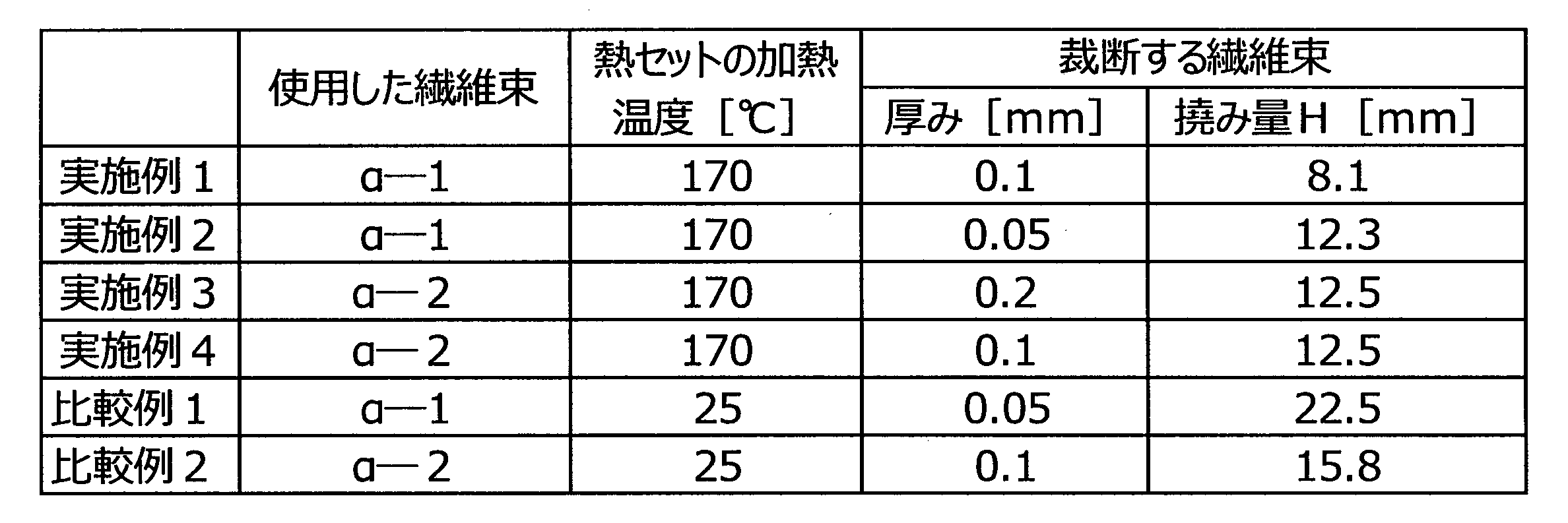
2 第2製造装置
13 裁断機
16 含浸部
50 開繊部
52、52A 分繊部
54、54A 熱セット部
100、200、300、500 繊維強化樹脂材料の製造装置 DESCRIPTION OF
Claims (14)
- 長尺の繊維束を開繊により幅方向に拡幅し、扁平な状態とする開繊工程と、
開繊後の繊維束を加熱して扁平な状態で熱セットする熱セット工程を有する、繊維強化樹脂材料の製造方法。 An opening process in which a long fiber bundle is widened in the width direction by opening, and is made flat.
A method for producing a fiber-reinforced resin material, comprising a heat setting step of heating a fiber bundle after opening and heat-setting in a flat state. - 前記繊維束として樹脂が付着した繊維束を用いる、請求項1に記載の繊維強化樹脂材料の製造方法。 The method for producing a fiber-reinforced resin material according to claim 1, wherein a fiber bundle to which a resin is attached is used as the fiber bundle.
- 前記繊維束としてサイズ剤が付着した繊維束を用いる、請求項1に記載の繊維強化樹脂材料の製造方法。 The method for producing a fiber-reinforced resin material according to claim 1, wherein a fiber bundle to which a sizing agent is attached is used as the fiber bundle.
- 前記開繊工程と前記熱セット工程の間に、開繊後の繊維束を分繊により幅方向に分割する分繊工程をさらに有する、請求項1~3のいずれか一項に記載の繊維強化樹脂材料の製造方法。 The fiber reinforcement according to any one of claims 1 to 3, further comprising a splitting step of dividing the fiber bundle after opening in the width direction by splitting between the opening step and the heat setting step. Manufacturing method of resin material.
- 複数の繊維束と樹脂を含有する繊維強化樹脂材料を製造する方法であって、前記熱セット工程後に、前記繊維束を連続的に裁断する工程を有する、請求項1~4のいずれか一項に記載の繊維強化樹脂材料の製造方法。 5. A method for producing a fiber reinforced resin material containing a plurality of fiber bundles and a resin, comprising a step of continuously cutting the fiber bundle after the heat setting step. The manufacturing method of the fiber reinforced resin material of description.
- 樹脂をシート状にした第1樹脂シート上に、前記の裁断された複数の繊維束をシート状に散布してシート状繊維束群を形成する散布工程と、前記シート状繊維束群上に、前記樹脂をシート状にした第2樹脂シートを貼り合わせて加圧し、前記シート状繊維束群に樹脂を含浸させて繊維強化樹脂材料を得る貼合含浸工程を有する、請求項5に記載の繊維強化樹脂材料の製造方法。 On the first resin sheet in the form of a resin, on the sheet-like fiber bundle group, a spreading step of spreading the plurality of cut fiber bundles into a sheet shape to form a sheet-like fiber bundle group, The fiber according to claim 5, further comprising a bonding impregnation step in which a second resin sheet in which the resin is formed into a sheet is bonded and pressed to impregnate the resin into the sheet-like fiber bundle group to obtain a fiber reinforced resin material. A method for producing a reinforced resin material.
- 複数の繊維束と樹脂を含有する繊維強化樹脂材料を製造する装置であって、
長尺の繊維束を開繊により幅方向に拡幅し、扁平な状態とする開繊部と、
開繊後の繊維束を加熱して扁平な状態で熱セットする熱セット部と、
を備えている、繊維強化樹脂材料の製造装置。 An apparatus for producing a fiber reinforced resin material containing a plurality of fiber bundles and a resin,
A widened fiber bundle is widened in the width direction by opening, and a flattened state is formed.
A heat setting section that heats the fiber bundle after opening and heat-sets it in a flat state;
An apparatus for producing a fiber-reinforced resin material. - 前記開繊部と前記熱セット部の間に、開繊後の繊維束を分繊により幅方向に分割する分繊部をさらに備える、請求項7に記載の繊維強化樹脂材料の製造装置。 The apparatus for producing a fiber-reinforced resin material according to claim 7, further comprising a splitting part that splits the fiber bundle after opening in the width direction by splitting between the opening part and the heat setting part.
- 前記熱セット部の後に、熱セット後の繊維束を連続的に裁断し、前記樹脂をシート状にした第1樹脂シート上に、裁断された複数の繊維束をシート状に散布してシート状繊維束群を形成する裁断機を備える、請求項7又は8に記載の繊維強化樹脂材料の製造装置。 After the heat setting portion, the fiber bundle after heat setting is continuously cut, and the plurality of cut fiber bundles are spread in a sheet form on the first resin sheet in which the resin is formed into a sheet form. The manufacturing apparatus of the fiber reinforced resin material of Claim 7 or 8 provided with the cutting machine which forms a fiber bundle group.
- 前記裁断機の後に、前記シート状繊維束群上に、前記樹脂をシート状にした第2樹脂シートを貼り合せて加圧し、前記シート状繊維束群に樹脂を含浸させて繊維強化樹脂材料とする含浸部を備える、請求項7~9のいずれか一項に記載の繊維強化樹脂材料の製造装置。 After the cutting machine, the sheet-like fiber bundle group is bonded with a second resin sheet in the form of a sheet and pressed, and the sheet-like fiber bundle group is impregnated with a resin to obtain a fiber-reinforced resin material. The apparatus for producing a fiber-reinforced resin material according to any one of claims 7 to 9, further comprising an impregnating part.
- 長尺の繊維束を連続的に裁断し、裁断された複数の繊維束で形成したシート状繊維束群に樹脂を含浸して繊維強化樹脂材料を製造する方法において、下記撓み試験で測定される撓み量Hが15mm未満の繊維束を裁断する、繊維強化樹脂材料の製造方法。
(撓み試験)
裁断する繊維束から長さ150mmの試験片を切り出し、前記試験片における長さ方向の第1末端から100mmの位置から第2末端までの部分を平面上に設置する。前記試験片における前記第1末端から100mmの部分を自由状態として、その状態における前記第1末端の下端と前記平面との距離を撓み量H(mm)とする。 In a method of manufacturing a fiber reinforced resin material by continuously cutting a long fiber bundle and impregnating a resin into a sheet-like fiber bundle group formed by a plurality of cut fiber bundles, the measurement is performed by the following bending test. A method for producing a fiber-reinforced resin material, wherein a fiber bundle having a deflection amount H of less than 15 mm is cut.
(Bending test)
A test piece having a length of 150 mm is cut out from the fiber bundle to be cut, and a portion from the first end in the length direction to the second end of the test piece is placed on a plane. A portion 100 mm from the first end of the test piece is in a free state, and the distance between the lower end of the first end and the plane in that state is defined as a deflection amount H (mm). - 長尺の繊維束を開繊により幅方向に拡幅して扁平な状態とし、開繊後の繊維束を連続的に裁断する、請求項11に記載の繊維強化樹脂材料の製造方法。 The method for producing a fiber-reinforced resin material according to claim 11, wherein the long fiber bundle is widened in the width direction by opening to obtain a flat state, and the fiber bundle after opening is continuously cut.
- 前記の開繊後の繊維束を加熱して扁平な状態で熱セットしてから裁断する、請求項12に記載の繊維強化樹脂材料の製造方法。 The method for producing a fiber-reinforced resin material according to claim 12, wherein the fiber bundle after opening is heated and set in a flat state and then cut.
- 前記の開繊後の繊維束を分繊により幅方向に分割してから裁断する、請求項12又13に記載の繊維強化樹脂材料の製造方法。 The method for producing a fiber-reinforced resin material according to claim 12 or 13, wherein the fiber bundle after opening is divided in the width direction by splitting and then cut.
Priority Applications (7)
| Application Number | Priority Date | Filing Date | Title |
|---|---|---|---|
| EP17782321.8A EP3444090B1 (en) | 2016-04-11 | 2017-04-07 | Method for manufacturing fiber reinforced resin material and apparatus for manufacturing fiber reinforced resin material |
| CN201780021030.2A CN109070389B (en) | 2016-04-11 | 2017-04-07 | Method for producing fiber-reinforced resin material and apparatus for producing fiber-reinforced resin material |
| ES17782321T ES2866904T3 (en) | 2016-04-11 | 2017-04-07 | Method for making fiber-reinforced resin material and apparatus for making fiber-reinforced resin material |
| JP2017523929A JP6409969B2 (en) | 2016-04-11 | 2017-04-07 | Sheet molding compound manufacturing method and sheet molding compound manufacturing apparatus |
| EP21156216.0A EP3838536A3 (en) | 2016-04-11 | 2017-04-07 | Method for manufacturing fiber reinforced resin material and apparatus for manufacturing fiber reinforced resin material |
| US16/135,098 US20190016102A1 (en) | 2016-04-11 | 2018-09-19 | Method for manufacturing fiber reinforced resin material and apparatus for manufacturing fiber reinforced resin material |
| US17/216,936 US20210213716A1 (en) | 2016-04-11 | 2021-03-30 | Method for manufacturing fiber reinforced resin material and apparatus for manufacturing fiber reinforced resin material |
Applications Claiming Priority (4)
| Application Number | Priority Date | Filing Date | Title |
|---|---|---|---|
| JP2016078938 | 2016-04-11 | ||
| JP2016-078938 | 2016-04-11 | ||
| JP2016-120017 | 2016-06-16 | ||
| JP2016120017 | 2016-06-16 |
Related Child Applications (1)
| Application Number | Title | Priority Date | Filing Date |
|---|---|---|---|
| US16/135,098 Continuation US20190016102A1 (en) | 2016-04-11 | 2018-09-19 | Method for manufacturing fiber reinforced resin material and apparatus for manufacturing fiber reinforced resin material |
Publications (1)
| Publication Number | Publication Date |
|---|---|
| WO2017179506A1 true WO2017179506A1 (en) | 2017-10-19 |
Family
ID=60042443
Family Applications (1)
| Application Number | Title | Priority Date | Filing Date |
|---|---|---|---|
| PCT/JP2017/014530 WO2017179506A1 (en) | 2016-04-11 | 2017-04-07 | Method for manufacturing fiber reinforced resin material and apparatus for manufacturing fiber reinforced resin material |
Country Status (6)
| Country | Link |
|---|---|
| US (2) | US20190016102A1 (en) |
| EP (2) | EP3838536A3 (en) |
| JP (1) | JP6409969B2 (en) |
| CN (2) | CN109070389B (en) |
| ES (1) | ES2866904T3 (en) |
| WO (1) | WO2017179506A1 (en) |
Cited By (3)
| Publication number | Priority date | Publication date | Assignee | Title |
|---|---|---|---|---|
| WO2019098370A1 (en) * | 2017-11-20 | 2019-05-23 | 三菱ケミカル株式会社 | Method and device for manufacturing fiber-reinforced resin molding material |
| JP2020002334A (en) * | 2018-06-26 | 2020-01-09 | 日星機械工業株式會社 | Smc manufacturing method and manufacturing device thereof |
| JP2020090608A (en) * | 2018-12-05 | 2020-06-11 | 三菱ケミカル株式会社 | Manufacturing method of sheet molding compound |
Families Citing this family (1)
| Publication number | Priority date | Publication date | Assignee | Title |
|---|---|---|---|---|
| JP6773222B2 (en) * | 2018-04-04 | 2020-10-21 | 三菱ケミカル株式会社 | Manufacturing method of fiber reinforced resin molding material and manufacturing equipment of fiber reinforced resin molding material |
Citations (7)
| Publication number | Priority date | Publication date | Assignee | Title |
|---|---|---|---|---|
| WO1999035326A1 (en) * | 1998-01-06 | 1999-07-15 | Toray Industries, Inc. | Carbon fibers and process for the production thereof |
| JP2001020181A (en) * | 1999-07-06 | 2001-01-23 | Toray Ind Inc | Carbon fiber and its production |
| JP2005281464A (en) * | 2004-03-29 | 2005-10-13 | Toho Tenax Co Ltd | Polyamide-coated carbon fiber and its production method |
| JP2006144168A (en) * | 2004-11-19 | 2006-06-08 | Toray Ind Inc | Carbon fiber bundle |
| JP2006219780A (en) * | 2005-02-10 | 2006-08-24 | Toray Ind Inc | Method for splitting carbon fiber |
| WO2011125396A1 (en) * | 2010-04-05 | 2011-10-13 | 日東紡績株式会社 | Process for production of glass fiber fabric having silica microparticles adhered thereon, glass fiber fabric having silica microparticles adhered thereon, and fiber-reinforced molded resin article |
| JP2014172998A (en) * | 2013-03-08 | 2014-09-22 | Teijin Ltd | Method for manufacturing a reinforcing fiber bundle |
Family Cites Families (19)
| Publication number | Priority date | Publication date | Assignee | Title |
|---|---|---|---|---|
| US3956055A (en) * | 1973-09-17 | 1976-05-11 | Material Systems Corporation | Composite panel and shape forming apparatus |
| JPH01163219A (en) * | 1987-12-19 | 1989-06-27 | Toyota Central Res & Dev Lab Inc | Production of fiber-reinforced resin composition |
| US5296064A (en) * | 1989-04-17 | 1994-03-22 | Georgia Tech Research Corp. | Flexible multiply towpreg tape from powder fusion coated towpreg and method for production thereof |
| JPH07115352B2 (en) * | 1990-01-23 | 1995-12-13 | 東レ株式会社 | Prepreg manufacturing method |
| US5102690A (en) * | 1990-02-26 | 1992-04-07 | Board Of Trustees Operating Michigan State University | Method coating fibers with particles by fluidization in a gas |
| US5123373A (en) * | 1990-02-26 | 1992-06-23 | Board Of Trustees Operating Michigan State University | Method for fiber coating with particles |
| JPH06200048A (en) * | 1992-12-28 | 1994-07-19 | Sekisui Chem Co Ltd | Production of fiber-reinforced thermoplastic resin sheet |
| US6508906B1 (en) * | 2000-03-15 | 2003-01-21 | Patent Holding Company | Carbon fiber-filled sheet molding compound and method of manufacturing same |
| US6385828B1 (en) * | 2001-08-28 | 2002-05-14 | Zoltek Companies, Inc. | Apparatus and method for splitting a tow of fibers |
| JP2005020181A (en) * | 2003-06-24 | 2005-01-20 | Kyocera Corp | Portable telephone set |
| US8652570B2 (en) * | 2006-11-16 | 2014-02-18 | Honeywell International Inc. | Process for forming unidirectionally oriented fiber structures |
| JP2008254191A (en) * | 2007-03-30 | 2008-10-23 | Honda Motor Co Ltd | Carbon fiber composite material manufacturing apparatus, carbon fiber composite material manufacturing method and carbon fiber composite material |
| KR101578045B1 (en) * | 2010-01-29 | 2015-12-16 | 도레이 카부시키가이샤 | Fiber-reinforced thermoplastic resin composition, reinforcing fiber bundle, and process for production of fiber-reinforced thermoplastic resin composition |
| US20120213997A1 (en) * | 2011-02-21 | 2012-08-23 | United States Council For Automotive Research | Fiber tow treatment apparatus and system |
| CN102179945B (en) * | 2011-04-25 | 2013-03-06 | 盐城市强力电工绝缘材料厂 | Production process of large-calibre epoxy glass fiber and braided strap winding extrusion draw pipe |
| KR20140105477A (en) * | 2011-12-22 | 2014-09-01 | 데이진 가부시키가이샤 | Method for manufacturing reinforcing fiber strands |
| CN106031919B (en) | 2014-10-16 | 2018-07-17 | 富士电机株式会社 | The cleaning device of the multi-way valve of beverage feeder |
| JP6468836B2 (en) | 2014-12-24 | 2019-02-13 | 花王株式会社 | Absorbent pad |
| CN105599171A (en) * | 2016-01-07 | 2016-05-25 | 威海光威复合材料股份有限公司 | Fiber expansion method for reinforced fiber beam |
-
2017
- 2017-04-07 JP JP2017523929A patent/JP6409969B2/en active Active
- 2017-04-07 ES ES17782321T patent/ES2866904T3/en active Active
- 2017-04-07 CN CN201780021030.2A patent/CN109070389B/en active Active
- 2017-04-07 EP EP21156216.0A patent/EP3838536A3/en not_active Withdrawn
- 2017-04-07 EP EP17782321.8A patent/EP3444090B1/en active Active
- 2017-04-07 CN CN202110630614.8A patent/CN113442334A/en active Pending
- 2017-04-07 WO PCT/JP2017/014530 patent/WO2017179506A1/en active Application Filing
-
2018
- 2018-09-19 US US16/135,098 patent/US20190016102A1/en not_active Abandoned
-
2021
- 2021-03-30 US US17/216,936 patent/US20210213716A1/en not_active Abandoned
Patent Citations (7)
| Publication number | Priority date | Publication date | Assignee | Title |
|---|---|---|---|---|
| WO1999035326A1 (en) * | 1998-01-06 | 1999-07-15 | Toray Industries, Inc. | Carbon fibers and process for the production thereof |
| JP2001020181A (en) * | 1999-07-06 | 2001-01-23 | Toray Ind Inc | Carbon fiber and its production |
| JP2005281464A (en) * | 2004-03-29 | 2005-10-13 | Toho Tenax Co Ltd | Polyamide-coated carbon fiber and its production method |
| JP2006144168A (en) * | 2004-11-19 | 2006-06-08 | Toray Ind Inc | Carbon fiber bundle |
| JP2006219780A (en) * | 2005-02-10 | 2006-08-24 | Toray Ind Inc | Method for splitting carbon fiber |
| WO2011125396A1 (en) * | 2010-04-05 | 2011-10-13 | 日東紡績株式会社 | Process for production of glass fiber fabric having silica microparticles adhered thereon, glass fiber fabric having silica microparticles adhered thereon, and fiber-reinforced molded resin article |
| JP2014172998A (en) * | 2013-03-08 | 2014-09-22 | Teijin Ltd | Method for manufacturing a reinforcing fiber bundle |
Cited By (6)
| Publication number | Priority date | Publication date | Assignee | Title |
|---|---|---|---|---|
| WO2019098370A1 (en) * | 2017-11-20 | 2019-05-23 | 三菱ケミカル株式会社 | Method and device for manufacturing fiber-reinforced resin molding material |
| JPWO2019098370A1 (en) * | 2017-11-20 | 2019-11-21 | 三菱ケミカル株式会社 | Fiber reinforced resin molding material manufacturing method and fiber reinforced resin molding material manufacturing apparatus |
| US11643513B2 (en) | 2017-11-20 | 2023-05-09 | Mitsubishi Chemical Corporation | Method and device for manufacturing fiber-reinforced resin molding material |
| JP2020002334A (en) * | 2018-06-26 | 2020-01-09 | 日星機械工業株式會社 | Smc manufacturing method and manufacturing device thereof |
| JP2020090608A (en) * | 2018-12-05 | 2020-06-11 | 三菱ケミカル株式会社 | Manufacturing method of sheet molding compound |
| JP7222234B2 (en) | 2018-12-05 | 2023-02-15 | 三菱ケミカル株式会社 | Method for producing carbon fiber bundle and method for producing sheet molding compound |
Also Published As
| Publication number | Publication date |
|---|---|
| CN113442334A (en) | 2021-09-28 |
| JP6409969B2 (en) | 2018-10-24 |
| EP3838536A3 (en) | 2021-09-22 |
| CN109070389A (en) | 2018-12-21 |
| EP3444090A4 (en) | 2019-07-24 |
| ES2866904T3 (en) | 2021-10-20 |
| US20210213716A1 (en) | 2021-07-15 |
| EP3838536A2 (en) | 2021-06-23 |
| EP3444090B1 (en) | 2021-03-24 |
| US20190016102A1 (en) | 2019-01-17 |
| JPWO2017179506A1 (en) | 2018-04-19 |
| CN109070389B (en) | 2021-06-15 |
| EP3444090A1 (en) | 2019-02-20 |
Similar Documents
| Publication | Publication Date | Title |
|---|---|---|
| JP7201063B2 (en) | METHOD FOR MANUFACTURING FIBER REINFORCED RESIN MOLDING MATERIAL | |
| JP6369622B2 (en) | Manufacturing method of fiber reinforced resin molding material | |
| JP6409969B2 (en) | Sheet molding compound manufacturing method and sheet molding compound manufacturing apparatus | |
| JP6593557B2 (en) | Fiber reinforced resin molding material manufacturing method and fiber reinforced resin molding material manufacturing apparatus | |
| WO2019194090A1 (en) | Method for preparing fiber-reinforced resin molding material, and apparatus for preparing fiber-reinforced resin molding material | |
| JP2018076620A (en) | Method for separating fiber bundle, apparatus for separating, method for manufacturing fiber reinforced resin material, and apparatus for manufacturing | |
| JP2017222108A (en) | Method for production of fiber-reinforced resin material |
Legal Events
| Date | Code | Title | Description |
|---|---|---|---|
| ENP | Entry into the national phase |
Ref document number: 2017523929 Country of ref document: JP Kind code of ref document: A |
|
| NENP | Non-entry into the national phase |
Ref country code: DE |
|
| WWE | Wipo information: entry into national phase |
Ref document number: 2017782321 Country of ref document: EP |
|
| ENP | Entry into the national phase |
Ref document number: 2017782321 Country of ref document: EP Effective date: 20181112 |
|
| 121 | Ep: the epo has been informed by wipo that ep was designated in this application |
Ref document number: 17782321 Country of ref document: EP Kind code of ref document: A1 |