WO2017179427A1 - 脈波検出装置、生体情報測定装置、脈波検出装置の装着補助部材 - Google Patents
脈波検出装置、生体情報測定装置、脈波検出装置の装着補助部材 Download PDFInfo
- Publication number
- WO2017179427A1 WO2017179427A1 PCT/JP2017/012942 JP2017012942W WO2017179427A1 WO 2017179427 A1 WO2017179427 A1 WO 2017179427A1 JP 2017012942 W JP2017012942 W JP 2017012942W WO 2017179427 A1 WO2017179427 A1 WO 2017179427A1
- Authority
- WO
- WIPO (PCT)
- Prior art keywords
- wrist
- pulse wave
- band
- auxiliary member
- wave detection
- Prior art date
- Legal status (The legal status is an assumption and is not a legal conclusion. Google has not performed a legal analysis and makes no representation as to the accuracy of the status listed.)
- Ceased
Links
Images


Classifications
-
- A—HUMAN NECESSITIES
- A61—MEDICAL OR VETERINARY SCIENCE; HYGIENE
- A61B—DIAGNOSIS; SURGERY; IDENTIFICATION
- A61B5/00—Measuring for diagnostic purposes; Identification of persons
- A61B5/02—Detecting, measuring or recording for evaluating the cardiovascular system, e.g. pulse, heart rate, blood pressure or blood flow
- A61B5/021—Measuring pressure in heart or blood vessels
- A61B5/02108—Measuring pressure in heart or blood vessels from analysis of pulse wave characteristics
-
- A—HUMAN NECESSITIES
- A61—MEDICAL OR VETERINARY SCIENCE; HYGIENE
- A61B—DIAGNOSIS; SURGERY; IDENTIFICATION
- A61B5/00—Measuring for diagnostic purposes; Identification of persons
- A61B5/02—Detecting, measuring or recording for evaluating the cardiovascular system, e.g. pulse, heart rate, blood pressure or blood flow
- A61B5/024—Measuring pulse rate or heart rate
- A61B5/0245—Measuring pulse rate or heart rate by using sensing means generating electric signals, i.e. ECG signals
-
- A—HUMAN NECESSITIES
- A61—MEDICAL OR VETERINARY SCIENCE; HYGIENE
- A61B—DIAGNOSIS; SURGERY; IDENTIFICATION
- A61B5/00—Measuring for diagnostic purposes; Identification of persons
- A61B5/68—Arrangements of detecting, measuring or recording means, e.g. sensors, in relation to patient
- A61B5/6801—Arrangements of detecting, measuring or recording means, e.g. sensors, in relation to patient specially adapted to be attached to or worn on the body surface
- A61B5/6802—Sensor mounted on worn items
- A61B5/681—Wristwatch-type devices
-
- A—HUMAN NECESSITIES
- A61—MEDICAL OR VETERINARY SCIENCE; HYGIENE
- A61B—DIAGNOSIS; SURGERY; IDENTIFICATION
- A61B5/00—Measuring for diagnostic purposes; Identification of persons
- A61B5/02—Detecting, measuring or recording for evaluating the cardiovascular system, e.g. pulse, heart rate, blood pressure or blood flow
- A61B5/021—Measuring pressure in heart or blood vessels
- A61B5/022—Measuring pressure in heart or blood vessels by applying pressure to close blood vessels, e.g. against the skin; Ophthalmodynamometers
-
- A—HUMAN NECESSITIES
- A61—MEDICAL OR VETERINARY SCIENCE; HYGIENE
- A61B—DIAGNOSIS; SURGERY; IDENTIFICATION
- A61B5/00—Measuring for diagnostic purposes; Identification of persons
- A61B5/72—Signal processing specially adapted for physiological signals or for diagnostic purposes
- A61B5/7235—Details of waveform analysis
Definitions
- the present invention relates to a pulse wave detection device, a biological information measurement device, and a mounting assistance member for the pulse wave detection device.
- Patent Document 1 describes a biological information measuring device that is attached to a wrist only with a housing that houses a sensor.
- the body of this biological information measuring device is provided with an opening for avoiding the ulna in the portion wound around the back of the hand when worn on the wrist, and this opening stabilizes the wearing state of the device on the wrist. It is possible to maintain it.
- Patent Document 2 describes a biological information measuring device in which both ends of a band part wound around a wrist are divided into three parts, and one end and the other end of each divided band part can be individually fixed. .
- a highly elastic band it is possible to improve the wearing feeling of the apparatus or the ease of wearing.
- a highly elastic band there is a possibility that the position of the sensor part may be shifted due to the expansion and contraction of the band part after fixing the device to the wrist, and it is difficult to measure biological information with high accuracy.
- the biological information measuring device of Patent Document 2 is configured to be able to adjust the pressing position of each sensor by fixing the sensor to each divided portion of the band.
- the sensor since the sensor is provided in the band itself, there is a high possibility that the sensor position is shifted due to the movement of the hand, and biological information cannot be measured with high accuracy.
- the above-described problem is not limited to a biological information measuring device that detects a pressure pulse wave using a pressure sensor or the like, and similarly occurs in a biological information measuring device that detects a volume pulse wave using a photoelectric sensor, for example.
- the present invention has been made in view of the above circumstances, and includes a pulse wave detection device capable of improving a feeling of wearing on a wrist and ease of wearing and detecting a pulse wave with high accuracy. It aims at providing the mounting
- the pulse wave detection device of the present invention is a pulse wave detection device used by being worn on the wrist of the measurement subject, and a main body including a detection unit capable of detecting a pulse wave from the radial artery of the measurement subject, A band-shaped band for fixing the main body part to the wrist; and a mounting auxiliary member configured to be detachable from the band, wherein the mounting auxiliary member is mounted with the mounting auxiliary member.
- the wrist comes into contact with the ulna or the vicinity of the radius of the wrist.
- the biological information measuring apparatus of the present invention includes the pulse wave detecting device and a biological information calculating unit that calculates biological information based on the pulse wave detected by the pulse wave detecting device.
- the mounting assisting member of the pulse wave detection device of the present invention includes a main body including a detection unit capable of detecting a pulse wave from the radial artery of the wrist of the measurement subject, and a band-like band for fixing the main body to the wrist
- a mounting assisting member for a pulse wave detection device having a structure in which the body portion is fixed to the wrist by the band to which the mounting assisting member is mounted. It contacts the ulna of the wrist or the vicinity of the radius.
- a pulse wave detection device capable of improving a feeling of wearing on the wrist and ease of wearing and detecting a pulse wave with high accuracy
- a biological information measurement device including the pulse wave detection device
- a pulse wave detection A mounting auxiliary member used in the apparatus can be provided.
- FIG. 4 is a perspective view schematically showing an external configuration of a mounting auxiliary member 30. 4 is a side view of the mounting auxiliary member 30.
- FIG. 6 is a perspective view schematically showing an external configuration of a mounting auxiliary member 50 that is a modification of the mounting auxiliary member 30.
- FIG. 1 It is a perspective view which shows typically the external appearance structure of 30 A of mounting assistance members which are the modifications of the mounting assistance member 30 of the biological information measuring device 100 shown in FIG. It is a figure which shows the modification of the mounting
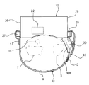
- FIG. 1 is a perspective view showing a schematic configuration of the appearance of a biological information measuring apparatus 100 according to an embodiment of the present invention.
- the biological information measuring device 100 is used by being worn on the wrist W of the left hand of the measurement subject.
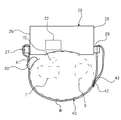
- FIG. 2 is a side view of the biological information measuring apparatus 100 shown in FIG. 1 as viewed from the elbow side of the subject's left hand (the subject's central side).
- the biological information measuring device 100 is worn on the wrist of the left hand will be described, but the biological information measuring device 100 can be worn on the wrist of the right hand.
- the biological information measuring apparatus 100 supports the housing 20 made of metal or resin, the belt-like band 40 that is a member for fixing the housing 20 to the wrist W, and the mounting of the housing 20 on the wrist W.
- a mounting assisting member 30 is provided.
- the housing 20 includes a pulse wave detector 22 that can detect a pulse wave (pressure pulse wave or volume pulse wave) from the radial artery TD along the rib T of the wrist W of the measurement subject.
- the housing 20 constitutes the main body of the biological information measuring device 100.
- the main body of the biological information measuring device 100 may be configured only by the housing 20 or a configuration in which the housing 20 and a sub-housing containing a battery or the like are connected (consisting of a plurality of housings). Configuration).
- the pulse wave detection unit 22 includes at least a sensor that can output a pulse wave as a signal.
- the pulse wave detection unit 22 includes a pressure sensor and a pressing mechanism that presses the pressure sensor against the skin, and detects the pressure pulse wave using the pressure sensor.
- the pulse wave detection part 22 has a photoelectric sensor, and detects a volume pulse wave from the signal detected by the photoelectric sensor.
- the case 20 is a substantially box-shaped member in the example of FIG. 1, and includes a pulse wave detection unit 22 and a heart rate, a pulse rate, or a blood pressure value based on the pulse wave detected by the pulse wave detection unit 22.
- a biological information calculation unit (not shown) that calculates the biological information.
- the biological information calculation unit may be provided in a device different from the biological information measuring device 100. That is, the housing 20 (main body part) of the biological information measuring device 100 only needs to include at least the pulse wave detection unit 22. In this case, the biological information measuring device 100 functions as a pulse wave detection device.
- the surface of the housing 20 facing the wrist W constitutes a detection surface.
- the detection surface may be substantially planar, but may be partially or entirely curved along the outer shape of the wrist W.
- the pulse wave detection unit 22 is provided at a position facing the radial artery TD with the detection surface facing the wrist W.
- the first end 28 on the ulna S side (the end surface on the ulna S side of the housing 20 in the example of FIGS. 1 and 2) of the circumferential ends of the wrist W in the housing 20 is first locked.
- a portion 29 is provided.
- the second end 26 on the rib T side (the end surface on the rib T side of the casing 20 in the example of FIGS. 1 and 2) of the circumferential ends of the wrist W in the casing 20 is second locked.
- a portion 27 is provided.
- the first locking portion 29 and the second locking portion 27 are for locking the band 40 to the housing 20.
- locking part 27 have a shape which has a hole part which can insert the band 40, respectively.
- the band 40 is routed so as to go around the wrist W in a state where the base end portion 41 is locked to the second locking portion 27 of the casing 20 (the wrist W is sandwiched between the band 40 and the casing 20).
- the casing 20 is fixed to the wrist W while maintaining the state in which the pulse wave detection unit 22 faces the radial artery TD.
- the band 40 is a member having rigidity lower than that of the housing 20, for example.
- a material of the band 40 for example, cloth, leather, rubber, or thin resin can be used.
- the base end portion 41 constituting one end in the longitudinal direction of the band 40 is locked in a folded state at a second locking portion 27 provided at the second end portion 26.
- the front end portion 43 constituting the other end of the band 40 in the longitudinal direction is locked in a folded state at a first locking portion 29 provided at the first end portion 28.
- the distal end portion 43 of the band 40 is inserted into the hole portion of the first locking portion 29 from the detection surface side.
- the distal end portion 43 passing through the hole is folded back in a substantially U shape in a direction away from the housing 20.
- Planar fasteners 42 are respectively formed on the surface of the tip portion 43 that faces away from the housing 20 and the surface of the tip portion 43 that faces the housing 20. By this planar fastener 42, the folded portion of the tip portion 43 is detachably locked to the band 40.
- the planar fastener 42 is a locking member for removably locking the tip 43 to the band 40.
- tip part 43 to the band 40 by the recessed part and the convex part which can be fitted to this may be sufficient.
- the mounting auxiliary member 30 is a member configured to be detachable from the band 40.
- the mounting assisting member 30 has a through-hole through which the band 40 can pass, and the band 40 is passed through the through-hole so that the mounting auxiliary member 30 is mounted on the band 40.
- the attachment assisting member 30 is preferably made of a material that can easily pass through the band 40 (for example, wood, metal, or resin).
- FIG. 3 is a plan view schematically showing the band 40 on which the mounting auxiliary member 30 is mounted.
- a direction Y shown in FIG. 3 indicates a longitudinal direction of the band 40.
- a direction X shown in FIG. 3 indicates a short direction perpendicular to the longitudinal direction of the band 40.
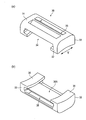
- FIG. 4 is a perspective view schematically showing the external configuration of the mounting assisting member 30.
- FIG. 4A shows a case where the case 20 is attached from the side opposite to the side facing the wrist W when the casing 20 is fixed to the wrist W by the band 40 to which the attachment auxiliary member 30 is attached (hereinafter referred to as a fixed state).
- FIG. 6 is a perspective view of the auxiliary member 30 as viewed.
- FIG. 4B is a perspective view of the mounting assisting member 30 viewed from the side facing the wrist W in the fixed state.
- FIG. 5 is a side view of the mounting assisting member 30.
- FIG. 5A is a view of the mounting assisting member 30 viewed from the direction Y in FIG.
- FIG. 5B is a view of the mounting assisting member 30 viewed from the direction X in FIG.
- FIG. 5 shows a direction Z (direction pressed against the skin in the fixed state) orthogonal to each of the direction X and the direction Y shown in FIG.
- the overall shape of the mounting assisting member 30 is close to a shape obtained by cutting a cylinder into half.
- the surface 31 of the mounting auxiliary member 30 has a through hole 34 that reaches one side surface 32 in the direction Y of the mounting auxiliary member 30 and a through hole 35 that reaches the other side surface 33 in the direction Y of the mounting auxiliary member 30. And are formed.
- the band 40 inserted into the through hole 34 is pulled out from the side surface 33 through the through hole 35.
- the attachment assisting member 30 is attached to the band 40 while being movable in the direction Y.
- the back surface 36 on the opposite side of the front surface 31 of the mounting assisting member 30 is a portion facing the wrist W of the measurement subject in a fixed state.
- a recess 36A is formed on the back surface 36.
- the recess 36A has a size that allows the projection of the ulna S of the wrist W of the measurement subject to be inserted.
- the attachment assisting member 30 is arranged and used at a position in contact with the vicinity of the ulna S of the wrist W in a fixed state.
- the vicinity of the ulna S of the wrist W refers to a range in which the ulna S can be touched with a finger on the wrist W.
- the presence of the recess 36A allows the protrusion of the ulna S to be inserted into the recess 36A even when the attachment assisting member 30 is in contact with the skin near the ulna S. Thereby, interference with the permite
- the back surface 36 that comes into contact with the wrist W in the fixed state is a curved surface that curves along the circumferential direction of the wrist W.
- the contact property of the back surface 36 and the wrist W can be made favorable, and the wearability of the biological information measuring device 100 can be improved.
- the measurement subject attaches the attachment assisting member 30 to the band 40 so that the back surface 36 of the attachment assisting member 30 faces the skin side. Then, the measurement subject inserts the distal end portion 43 of the band 40 into the hole portion of the first locking portion 29 of the housing 20 from the detection surface side. In this state, the measurement subject moves the mounting auxiliary member 30 along the longitudinal direction of the band 40 to finely adjust the position of the mounting auxiliary member 30, and the projection of the ulna S enters the recess 36 ⁇ / b> A of the mounting auxiliary member 30. Adjust as follows.
- the measurement subject folds and pulls the distal end portion 43 that has passed through the hole of the first locking portion 29 in a direction away from the housing 20 to adjust the tightening degree of the band 40. Finally, the measurement subject locks the distal end portion 43 to the band 40 via the planar fastener 42 and completes the wearing of the biological information measuring device 100.
- the pressure applied to the band 40 from the projection of the ulna S can be absorbed by the concave portion 36 ⁇ / b> A of the attachment auxiliary member 30. For this reason, when the band 40 is tightened, the ulna S does not get in the way and the feeling of wearing or the ease of wearing of the biological information measuring device 100 is not impaired, and the feeling of wearing and the ease of wearing can be improved. . In addition, it is possible to prevent the apparatus from being displaced after the biological information measuring apparatus 100 is attached.
- the biological information measuring apparatus 100 since there is no restriction on the material of the band 40, a material having elasticity that is ideal for fixing the housing 20 can be adopted, and the positional displacement of the apparatus can be prevented.
- the pulse wave detection accuracy can be improved.
- the mounting assisting member 30 since the mounting assisting member 30 is disposed between the wrist W and the band 40, even when a gap is generated between the wrist W and the band 40, the mounting assisting member 30 causes this. The gap can be filled. For this reason, biological information measuring device 100 can be stuck to wrist W, and it can prevent that a position shift of a device arises after wearing of biological information measuring device 100. As a result, pulse wave detection accuracy can be improved.
- the back surface 36 of the mounting assisting member 30 that comes into contact with the wrist W in the fixed state is curved along the circumferential direction of the wrist W. For this reason, the adhesiveness of the mounting
- the mounting assisting member 30 may be configured as shown in FIG. 6, for example.
- FIG. 6 is a perspective view schematically showing an external configuration of a mounting assisting member 50 that is a modification of the mounting assisting member 30.
- the overall shape of the mounting auxiliary member 50 is close to a shape obtained by cutting a cylinder into half.
- a through hole 54 that reaches the side surface 52 in the direction Y of the mounting auxiliary member 50 is formed on the surface 51 of the mounting auxiliary member 50.
- the band 40 inserted into the through hole 54 from the side surface 52 side is pulled out from the surface 51 side.
- the attachment auxiliary member 50 is attached to the band 40 in a state where the attachment auxiliary member 50 can move in the direction Y.
- the back surface 56 on the opposite side of the front surface 51 of the mounting assisting member 50 is a portion facing the wrist W of the measurement subject in a fixed state.
- a concave portion 56 ⁇ / b> A is formed on the back surface 56.
- the concave portion 56A has such a size that the projection of the ulna S of the wrist W of the measurement subject can be inserted.
- the recess 56A also serves as a part of the through hole 54.
- FIG. 7 is a perspective view schematically showing an external configuration of a mounting auxiliary member 30A that is a modification of the mounting auxiliary member 30 of the biological information measuring apparatus 100 shown in FIG.
- the elastic member 37 covers the concave portion 36A of the mounting auxiliary member 30 and is fixed to the back surface 36.
- the portion overlapping the concave portion 36A has a shape recessed toward the concave portion 36A. Due to this hollow shape, the projection of the ulna S is not prevented from being inserted into the recess 36A. In addition, when the thing with high elasticity is used as the elastic member 37, this hollow is not essential.
- the surface of the elastic member 37 on the back surface 36 of the auxiliary mounting member 30 is a curved surface reflecting the curved shape of the back surface 36.
- the elastic member 37 is a part that comes into contact with the skin, an optimal material having a lower rigidity than the mounting auxiliary member 30 is selected in consideration of the mounting feeling of the biological information measuring device 100.
- rubber or sponge can be used as the elastic member 37.
- the portion in contact with the skin becomes the elastic member 37, so that the attachment assisting member 30A can be satisfactorily contacted with the skin, and the wearing feeling of the biological information measuring apparatus 100 Can be improved.
- the elastic member 37 having a large frictional force against the skin it is possible to add a non-slip function to the mounting assisting member 30A, and to shift the position of the apparatus after the biological information measuring apparatus 100 is mounted. Can be prevented.
- the mounting auxiliary member 30 described in FIGS. 3 to 5 has the same configuration in the direction Z of the back surface 36 at both ends in the direction X.
- the positions in the direction Z of the back surface 36 at both ends are preferably different.
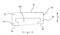
- FIG. 8 is a view showing a modification of the mounting assisting member 30 of the biological information measuring apparatus 100 shown in FIG.
- FIG. 8 is a view showing a state in which the mounting auxiliary member 30 is viewed from the direction Y shown in FIG.
- the attachment assisting member 30 shown in FIG. 8 includes a back surface 36 of an end portion (distal end portion) 39 disposed on the distal side in the direction X in the fixed state and an end portion disposed on the central side in the direction X in the fixed state.
- the back surface 36 of the (central side end) 38 is in a different position in the direction Z.
- the position of the back surface 36 of the distal side end portion 39 in the direction Z is The center side end 38 is located farther from the reference position than the position in the direction Z of the back surface 36.
- the configuration shown in FIG. 8 can prevent the attachment assisting member 30 from being inclined in the direction Z due to the difference in the thickness of the wrist. For this reason, the twist of the band 40 can be prevented and the wearability of the biological information measuring device 100 can be improved.
- the mounting assisting member 30 of the biological information measuring device 100 may be detachable from the band 40 by a locking member such as a planar fastener.
- the mounting assisting member 30 is connected to the band 40 by combining the planar fastener provided on the surface facing the wrist of the band 40 and the surface fastener provided on the surface 31 of the mounting assisting member 30. It is attached to.
- the mounting assisting member 30 may be used by being mounted at a position in contact with the vicinity of the rib T of the wrist W in a fixed state.
- the band 40 can be attached in the vicinity of the second locking portion 27.
- the back surface of the mounting auxiliary member 30 is in contact with the vicinity of the rib T of the wrist W.
- the vicinity of the rib T of the wrist W refers to a range in which the rib T can be touched with a finger on the wrist W.
- the recess 36A is sized so that the protrusion of the rib T can be inserted, the protrusion of the rib T can be recessed even when the attachment assisting member 30 is in contact with the skin near the rib T. 36A can be inserted. Thereby, interference with the protrusion of the rib T and the mounting auxiliary member 30 can be prevented, and the mounting property of the biological information measuring device 100 can be improved.
- the mounting assisting member 30 has the recess 36A on the back surface, but this recess 36A is not essential.
- the material constituting the back surface of the mounting assisting member 30 is a stretchable material and has a certain thickness, or as shown in FIG. 7, the back surface of the mounting assisting member 30 is stretchable and to some extent.
- the elastic member having a thickness of is fixed, the pressure of the ulna or rib protrusion can be absorbed by the material or the elastic member without the recess 36A. It is possible to prevent interference.
- the disclosed pulse wave detection device is a pulse wave detection device used by being worn on the wrist of the measurement subject, and a main body including a detection unit capable of detecting a pulse wave from the radial artery of the measurement subject, A band-shaped band for fixing the main body part to the wrist; and a mounting auxiliary member configured to be detachable from the band, wherein the mounting auxiliary member is mounted with the mounting auxiliary member.
- the wrist comes into contact with the ulna or the vicinity of the radius of the wrist.
- a concave portion into which the ulna of the wrist or the protrusion of the rib can be inserted is formed in a portion facing the wrist in the fixed state.
- the surface of the attachment assisting member that contacts the wrist is curved along the circumferential direction of the wrist.
- the contact surfaces of the both ends of the attachment assisting member in the short direction of the band in a state where the attachment assisting member is attached to the band are short of the band.
- the positions in the direction orthogonal to the hand direction and the longitudinal direction are different.
- a surface of the mounting assisting member that contacts the wrist is covered with an elastic member.
- the disclosed biological information measuring device includes the pulse wave detection device and a biological information calculation unit that calculates biological information based on the pulse wave detected by the pulse wave detection device.
- the disclosed mounting assisting member of the pulse wave detection device includes a main body unit including a detection unit capable of detecting a pulse wave from a radial artery of a wrist of a measurement subject, and a band-shaped band for fixing the main body unit to the wrist
- a mounting assisting member for a pulse wave detection device having a structure in which the body portion is fixed to the wrist by the band to which the mounting assisting member is mounted. It contacts the ulna of the wrist or the vicinity of the radius.
- the disclosed mounting assisting member of the pulse wave detection device is formed with a recess into which the ulna or rib projection of the wrist can be inserted in a portion facing the wrist in the fixed state.
- the surface of the mounting assisting member that contacts the wrist is curved along the circumferential direction of the wrist.
- the mounting assisting member of the disclosed pulse wave detection device is configured so that the contact surfaces of the both ends of the mounting assisting member in the short direction of the band in the state of being mounted on the band are the short sides of the band The positions in the direction orthogonal to the direction and the longitudinal direction are different.
- the surface in contact with the wrist is covered with an elastic member.
- the present invention is particularly convenient and effective when applied to a blood pressure monitor or the like.
Landscapes
- Health & Medical Sciences (AREA)
- Life Sciences & Earth Sciences (AREA)
- Cardiology (AREA)
- Engineering & Computer Science (AREA)
- Animal Behavior & Ethology (AREA)
- Public Health (AREA)
- Biomedical Technology (AREA)
- Heart & Thoracic Surgery (AREA)
- Medical Informatics (AREA)
- Molecular Biology (AREA)
- Pathology (AREA)
- Surgery (AREA)
- General Health & Medical Sciences (AREA)
- Biophysics (AREA)
- Veterinary Medicine (AREA)
- Physics & Mathematics (AREA)
- Physiology (AREA)
- Vascular Medicine (AREA)
- Signal Processing (AREA)
- Measuring Pulse, Heart Rate, Blood Pressure Or Blood Flow (AREA)
Priority Applications (3)
| Application Number | Priority Date | Filing Date | Title |
|---|---|---|---|
| EP17782245.9A EP3443894B1 (en) | 2016-04-15 | 2017-03-29 | Pulse wave detection device and biological information measuring device |
| CN201780023468.4A CN109069022B (zh) | 2016-04-15 | 2017-03-29 | 脉搏波检测装置、生物信息测量装置、脉搏波检测装置的安装辅助构件 |
| US16/158,462 US20190038154A1 (en) | 2016-04-15 | 2018-10-12 | Pulse wave detection device, biological information measuring device, wearing auxiliary member of pulse wave detection device |
Applications Claiming Priority (2)
| Application Number | Priority Date | Filing Date | Title |
|---|---|---|---|
| JP2016082370A JP6662167B2 (ja) | 2016-04-15 | 2016-04-15 | 脈波検出装置、生体情報測定装置、脈波検出装置の装着補助部材 |
| JP2016-082370 | 2016-04-15 |
Related Child Applications (1)
| Application Number | Title | Priority Date | Filing Date |
|---|---|---|---|
| US16/158,462 Continuation US20190038154A1 (en) | 2016-04-15 | 2018-10-12 | Pulse wave detection device, biological information measuring device, wearing auxiliary member of pulse wave detection device |
Publications (1)
| Publication Number | Publication Date |
|---|---|
| WO2017179427A1 true WO2017179427A1 (ja) | 2017-10-19 |
Family
ID=60042491
Family Applications (1)
| Application Number | Title | Priority Date | Filing Date |
|---|---|---|---|
| PCT/JP2017/012942 Ceased WO2017179427A1 (ja) | 2016-04-15 | 2017-03-29 | 脈波検出装置、生体情報測定装置、脈波検出装置の装着補助部材 |
Country Status (5)
| Country | Link |
|---|---|
| US (1) | US20190038154A1 (enExample) |
| EP (1) | EP3443894B1 (enExample) |
| JP (1) | JP6662167B2 (enExample) |
| CN (1) | CN109069022B (enExample) |
| WO (1) | WO2017179427A1 (enExample) |
Families Citing this family (7)
| Publication number | Priority date | Publication date | Assignee | Title |
|---|---|---|---|---|
| KR102758584B1 (ko) * | 2019-08-05 | 2025-01-21 | 삼성전자주식회사 | 생체 정보 측정 장치 및 방법 |
| CN111227807A (zh) * | 2020-02-12 | 2020-06-05 | 萌宝信息技术(上海)有限公司 | 一种便携式中医脉象查询设备及其使用方法 |
| KR102471315B1 (ko) * | 2020-10-26 | 2022-11-29 | (주)신라시스템 | 신체상태 측정 및 분석장치 |
| CN112515648B (zh) * | 2020-12-18 | 2023-06-27 | 云镶医疗器械(云南)有限公司 | 一种具有连接件的腕带、电子血压计及生命体征监护仪 |
| JP2023111693A (ja) * | 2022-01-31 | 2023-08-10 | ミネベアミツミ株式会社 | 脈波測定装置 |
| CN114668374B (zh) * | 2022-03-29 | 2024-08-13 | 青岛市中医医院(青岛市海慈医院、青岛市康复医学研究所) | 基于束缚腕部的护理呼吸科脉搏测量装置 |
| KR102800699B1 (ko) * | 2024-03-27 | 2025-04-28 | 황윤진 | 자석 손목보호대 |
Citations (6)
| Publication number | Priority date | Publication date | Assignee | Title |
|---|---|---|---|---|
| JPH0852118A (ja) * | 1994-08-11 | 1996-02-27 | Seiko Epson Corp | 携帯型脈波計測装置 |
| JP2003210424A (ja) * | 2002-01-28 | 2003-07-29 | Seiko Instruments Inc | 生体情報観測装置 |
| JP2004305629A (ja) * | 2003-04-10 | 2004-11-04 | Seiko Instruments Inc | 脈波検出装置 |
| JP2008168054A (ja) * | 2007-01-15 | 2008-07-24 | Citizen Holdings Co Ltd | 手首装着型の生体測定装置用のバンド |
| JP2009240511A (ja) * | 2008-03-31 | 2009-10-22 | Citizen Holdings Co Ltd | 生体測定装置 |
| JP2015503933A (ja) * | 2011-08-30 | 2015-02-05 | オキシトーン メディカル エルティディ. | 身体に装着可能な脈拍計/酸素濃度計 |
Family Cites Families (1)
| Publication number | Priority date | Publication date | Assignee | Title |
|---|---|---|---|---|
| JP2002523122A (ja) * | 1998-08-24 | 2002-07-30 | シー. バラク、マーティン | 脈の伝達時間を測定する装置及び方法 |
-
2016
- 2016-04-15 JP JP2016082370A patent/JP6662167B2/ja active Active
-
2017
- 2017-03-29 CN CN201780023468.4A patent/CN109069022B/zh active Active
- 2017-03-29 WO PCT/JP2017/012942 patent/WO2017179427A1/ja not_active Ceased
- 2017-03-29 EP EP17782245.9A patent/EP3443894B1/en active Active
-
2018
- 2018-10-12 US US16/158,462 patent/US20190038154A1/en not_active Abandoned
Patent Citations (6)
| Publication number | Priority date | Publication date | Assignee | Title |
|---|---|---|---|---|
| JPH0852118A (ja) * | 1994-08-11 | 1996-02-27 | Seiko Epson Corp | 携帯型脈波計測装置 |
| JP2003210424A (ja) * | 2002-01-28 | 2003-07-29 | Seiko Instruments Inc | 生体情報観測装置 |
| JP2004305629A (ja) * | 2003-04-10 | 2004-11-04 | Seiko Instruments Inc | 脈波検出装置 |
| JP2008168054A (ja) * | 2007-01-15 | 2008-07-24 | Citizen Holdings Co Ltd | 手首装着型の生体測定装置用のバンド |
| JP2009240511A (ja) * | 2008-03-31 | 2009-10-22 | Citizen Holdings Co Ltd | 生体測定装置 |
| JP2015503933A (ja) * | 2011-08-30 | 2015-02-05 | オキシトーン メディカル エルティディ. | 身体に装着可能な脈拍計/酸素濃度計 |
Non-Patent Citations (1)
| Title |
|---|
| See also references of EP3443894A4 * |
Also Published As
| Publication number | Publication date |
|---|---|
| EP3443894A1 (en) | 2019-02-20 |
| EP3443894A4 (en) | 2019-11-20 |
| CN109069022A (zh) | 2018-12-21 |
| JP2017189535A (ja) | 2017-10-19 |
| JP6662167B2 (ja) | 2020-03-11 |
| US20190038154A1 (en) | 2019-02-07 |
| CN109069022B (zh) | 2021-10-29 |
| EP3443894B1 (en) | 2021-12-08 |
Similar Documents
| Publication | Publication Date | Title |
|---|---|---|
| JP6662167B2 (ja) | 脈波検出装置、生体情報測定装置、脈波検出装置の装着補助部材 | |
| US11147512B2 (en) | Pulse wave detection device and biometric information measurement device | |
| JP2017189535A5 (enExample) | ||
| JP2017184998A5 (enExample) | ||
| JP2017051273A (ja) | 圧脈波検出装置 | |
| JP6682971B2 (ja) | 脈波検出装置及び生体情報測定装置 | |
| JP6682970B2 (ja) | 脈波検出装置及び生体情報測定装置 | |
| CN108024734B (zh) | 脉搏波检测装置 | |
| JP6540396B2 (ja) | 脈波検出装置 | |
| CN107920756B (zh) | 脉搏波检测装置 | |
| US20240065664A1 (en) | Physiological signal measurement device | |
| JP4248917B2 (ja) | 脈波検出装置 | |
| JP2019136231A (ja) | 脈波検出装置及びこれを装着したヘルメット | |
| JP2017063984A (ja) | 脈波検出装置 |
Legal Events
| Date | Code | Title | Description |
|---|---|---|---|
| NENP | Non-entry into the national phase |
Ref country code: DE |
|
| WWE | Wipo information: entry into national phase |
Ref document number: 2017782245 Country of ref document: EP |
|
| ENP | Entry into the national phase |
Ref document number: 2017782245 Country of ref document: EP Effective date: 20181115 |
|
| 121 | Ep: the epo has been informed by wipo that ep was designated in this application |
Ref document number: 17782245 Country of ref document: EP Kind code of ref document: A1 |