WO2017179281A1 - 洗浄部材及び基板洗浄装置 - Google Patents
洗浄部材及び基板洗浄装置 Download PDFInfo
- Publication number
- WO2017179281A1 WO2017179281A1 PCT/JP2017/005159 JP2017005159W WO2017179281A1 WO 2017179281 A1 WO2017179281 A1 WO 2017179281A1 JP 2017005159 W JP2017005159 W JP 2017005159W WO 2017179281 A1 WO2017179281 A1 WO 2017179281A1
- Authority
- WO
- WIPO (PCT)
- Prior art keywords
- substrate
- cleaning member
- cleaning
- skin layer
- covered
- Prior art date
- Legal status (The legal status is an assumption and is not a legal conclusion. Google has not performed a legal analysis and makes no representation as to the accuracy of the status listed.)
- Ceased
Links
Images





Classifications
-
- H—ELECTRICITY
- H10—SEMICONDUCTOR DEVICES; ELECTRIC SOLID-STATE DEVICES NOT OTHERWISE PROVIDED FOR
- H10P—GENERIC PROCESSES OR APPARATUS FOR THE MANUFACTURE OR TREATMENT OF DEVICES COVERED BY CLASS H10
- H10P72/00—Handling or holding of wafers, substrates or devices during manufacture or treatment thereof
- H10P72/04—Apparatus for manufacture or treatment
- H10P72/0402—Apparatus for fluid treatment
- H10P72/0406—Apparatus for fluid treatment for cleaning followed by drying, rinsing, stripping, blasting or the like
- H10P72/0411—Apparatus for fluid treatment for cleaning followed by drying, rinsing, stripping, blasting or the like for wet cleaning or washing
- H10P72/0412—Apparatus for fluid treatment for cleaning followed by drying, rinsing, stripping, blasting or the like for wet cleaning or washing using mainly scrubbing means, e.g. brushes
-
- B—PERFORMING OPERATIONS; TRANSPORTING
- B08—CLEANING
- B08B—CLEANING IN GENERAL; PREVENTION OF FOULING IN GENERAL
- B08B1/00—Cleaning by methods involving the use of tools
- B08B1/10—Cleaning by methods involving the use of tools characterised by the type of cleaning tool
- B08B1/14—Wipes; Absorbent members, e.g. swabs or sponges
-
- B—PERFORMING OPERATIONS; TRANSPORTING
- B08—CLEANING
- B08B—CLEANING IN GENERAL; PREVENTION OF FOULING IN GENERAL
- B08B1/00—Cleaning by methods involving the use of tools
- B08B1/20—Cleaning of moving articles, e.g. of moving webs or of objects on a conveyor
-
- B—PERFORMING OPERATIONS; TRANSPORTING
- B08—CLEANING
- B08B—CLEANING IN GENERAL; PREVENTION OF FOULING IN GENERAL
- B08B11/00—Cleaning flexible or delicate articles by methods or apparatus specially adapted thereto
-
- H—ELECTRICITY
- H10—SEMICONDUCTOR DEVICES; ELECTRIC SOLID-STATE DEVICES NOT OTHERWISE PROVIDED FOR
- H10P—GENERIC PROCESSES OR APPARATUS FOR THE MANUFACTURE OR TREATMENT OF DEVICES COVERED BY CLASS H10
- H10P72/00—Handling or holding of wafers, substrates or devices during manufacture or treatment thereof
- H10P72/04—Apparatus for manufacture or treatment
- H10P72/0402—Apparatus for fluid treatment
- H10P72/0406—Apparatus for fluid treatment for cleaning followed by drying, rinsing, stripping, blasting or the like
- H10P72/0411—Apparatus for fluid treatment for cleaning followed by drying, rinsing, stripping, blasting or the like for wet cleaning or washing
-
- H—ELECTRICITY
- H10—SEMICONDUCTOR DEVICES; ELECTRIC SOLID-STATE DEVICES NOT OTHERWISE PROVIDED FOR
- H10P—GENERIC PROCESSES OR APPARATUS FOR THE MANUFACTURE OR TREATMENT OF DEVICES COVERED BY CLASS H10
- H10P72/00—Handling or holding of wafers, substrates or devices during manufacture or treatment thereof
- H10P72/04—Apparatus for manufacture or treatment
- H10P72/0402—Apparatus for fluid treatment
- H10P72/0406—Apparatus for fluid treatment for cleaning followed by drying, rinsing, stripping, blasting or the like
- H10P72/0411—Apparatus for fluid treatment for cleaning followed by drying, rinsing, stripping, blasting or the like for wet cleaning or washing
- H10P72/0414—Apparatus for fluid treatment for cleaning followed by drying, rinsing, stripping, blasting or the like for wet cleaning or washing using mainly spraying means, e.g. nozzles
-
- H—ELECTRICITY
- H10—SEMICONDUCTOR DEVICES; ELECTRIC SOLID-STATE DEVICES NOT OTHERWISE PROVIDED FOR
- H10P—GENERIC PROCESSES OR APPARATUS FOR THE MANUFACTURE OR TREATMENT OF DEVICES COVERED BY CLASS H10
- H10P72/00—Handling or holding of wafers, substrates or devices during manufacture or treatment thereof
- H10P72/70—Handling or holding of wafers, substrates or devices during manufacture or treatment thereof for supporting or gripping
- H10P72/76—Handling or holding of wafers, substrates or devices during manufacture or treatment thereof for supporting or gripping using mechanical means, e.g. clamps or pinches
- H10P72/7604—Handling or holding of wafers, substrates or devices during manufacture or treatment thereof for supporting or gripping using mechanical means, e.g. clamps or pinches the wafers being placed on a susceptor, stage or support
- H10P72/7608—Handling or holding of wafers, substrates or devices during manufacture or treatment thereof for supporting or gripping using mechanical means, e.g. clamps or pinches the wafers being placed on a susceptor, stage or support characterised by a plurality of separate clamping members, e.g. clamping fingers
-
- B—PERFORMING OPERATIONS; TRANSPORTING
- B08—CLEANING
- B08B—CLEANING IN GENERAL; PREVENTION OF FOULING IN GENERAL
- B08B3/00—Cleaning by methods involving the use or presence of liquid or steam
- B08B3/02—Cleaning by the force of jets or sprays
- B08B3/022—Cleaning travelling work
Definitions
- the present invention relates to a cleaning member and a substrate cleaning apparatus used for cleaning a substrate such as a semiconductor wafer.
- a member having a skin layer formed thereon is known as a cleaning member used for CMP cleaning.
- a cleaning member used for CMP cleaning.
- a mold is formed, only the contact surface is cut, and the skin layer is formed on the surface facing the inner contact surface of the mold (side surface of the cleaning member). is doing.
- this cleaning member having a skin layer is used, since the pore diameter of the continuous pores is small and the porosity is low compared to the inside made of a sponge, it is possible to hold a large amount of liquid inside, and the surface Therefore, it is difficult for the liquid inside to flow out, and desired water absorption performance and water supply performance can be obtained.
- JP 2011-56382 A discloses a sponge with a shaft having a skin layer.
- a cleaning member used for cleaning CMP is provided with a skin layer on the side surface, there is a concern that the side skin layer may enter the contact surface and cause contact contamination (can cause unevenness in the circumferential direction) (See FIG. 12).
- the cleaning liquid colliding with the side surface enters the cleaning member, and the particles contained in the cleaning liquid enter the cleaning member and are mixed.
- the substrate The particles may adhere to the surface. If the skin layer is not provided, the strength is weakened and the cleaning characteristics may not be maintained. For this reason, a cleaning member in which the skin layer is not completely provided is not preferable.
- the present invention has been made in view of these points, and a cleaning member and a substrate cleaning that prevent contamination from the skin layer while preventing particles contained in the cleaning liquid from entering and mixing inside as much as possible. Providing equipment.
- the cleaning member according to the present invention comprises: A cleaning member used for cleaning a substrate, A tip surface that is in contact with the substrate when cleaning the substrate and is not covered with a skin layer; A peripheral portion having a covering portion provided on the base side and having a peripheral surface covered with a skin layer; and an exposed portion provided on the distal end side and having a peripheral surface not covered with the skin layer; May be provided.
- the height of the exposed portion may be equal to or greater than the pushing length compressed when the cleaning member is pushed.
- the exposed portion may have a height of 1 mm to 5 mm.
- the base end surface may not be covered with the skin layer.
- the cleaning member may be a pencil cleaning member.
- the cleaning member may be a nodule.
- the distal end portion of the cleaning member may have a sectional area on the distal end side that is smaller than a sectional area on the proximal end side.
- the substrate cleaning apparatus comprises: A substrate holder for holding the substrate; A cleaning member according to any one of the above concepts 1 to 7, which is used for cleaning the substrate; Is provided.
- the front end surface of the cleaning member is not covered with the skin layer, and the peripheral portion of the cleaning member is provided on the base side, and the front end surface is covered with the skin layer. And an exposed portion whose peripheral surface is not covered with a skin layer. For this reason, it is possible to prevent the skin layer from coming into contact with the substrate while preventing the particles contained in the cleaning liquid from entering the inside, and to prevent contact contamination due to the skin layer coming into contact with the substrate. It can be prevented as much as possible.
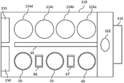
- FIG. 1 is an upper plan view showing the overall configuration of a substrate processing apparatus including a substrate cleaning apparatus according to a first embodiment of the present invention.
- FIG. 2 is a perspective view of the first substrate cleaning apparatus according to the embodiment of the present invention.
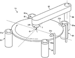
- FIG. 3 is a perspective view of the second substrate cleaning apparatus according to the embodiment of the present invention.
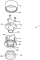
- FIG. 4 is a perspective view showing one aspect of a pencil cleaning member that can be used in the second substrate cleaning apparatus according to the embodiment of the present invention.
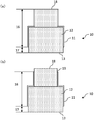
- FIGS. 5A to 5G are side sectional views showing various modes of the cleaning member used in the embodiment of the present invention.
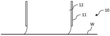
- FIG. 6 is a side cross-sectional view showing an aspect when the substrate is cleaned with the cleaning member used in the embodiment of the present invention.
- FIG. 7 (a) and 7 (b) are side sectional views showing aspects of the cleaning member used in the modification of the embodiment of the present invention.
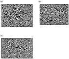
- FIG. 8A is an SEM photograph showing the sponge part enlarged 50 times
- FIG. 8B is an SEM photograph showing the sponge part enlarged 250 times.
- FIGS. 9A and 9B are SEM photographs showing the skin layer magnified 50 times
- FIG. 9C is an SEM photograph showing the skin layer magnified 250 times.
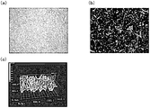
- FIG. 10 (a) is a photograph showing the sponge part enlarged 50 times
- FIG. 10 (b) is a 3D photograph showing the sponge part enlarged 50 times. ) Shows a measurement result by a laser in which the sponge part is enlarged 50 times.
- FIG. 10 (a) is a photograph showing the sponge part enlarged 50 times
- FIG. 10 (b) is a 3D photograph showing the sponge part enlarged 50 times. ) Shows a measurement result by a laser in which the sponge part is enlarged 50 times.
- FIG. 11A is a photograph showing the skin layer enlarged 50 times
- FIG. 11B is a 3D photograph showing the skin layer enlarged 50 times
- FIG. 12 Shows the measurement results with a laser showing the skin layer magnified 50 times.
- FIG. 12 is a photograph showing an example of the substrate surface after cleaning when the substrate is cleaned in a mode in which the skin layer is provided on the side surface of the cleaning member (pencil cleaning member), and fine dust adheres to the substrate. It is a photograph for showing that it is.
- FIG. 1 to FIG. 11 are diagrams for explaining an embodiment of the present invention.
- the substrate processing apparatus has a substantially rectangular housing 110 and a load port 112 on which a substrate cassette for stocking a large number of substrates W is placed.
- the load port 112 is disposed adjacent to the housing 110.
- the load port 112 can be equipped with an open cassette, a SMIF (Standard Mechanical Interface) pod, or a FOUP (Front Opening Unified Unified Pod).
- the SMIF pod and the FOUP are sealed containers that can maintain an environment independent of the external space by accommodating a substrate cassette inside and covering with a partition wall.
- An example of the substrate W is a semiconductor wafer.
- polishing units 114a to 114d Inside the housing 110, a plurality of (four in the embodiment shown in FIG. 1) polishing units 114a to 114d, a first substrate cleaning device 50 and a second substrate cleaning device 55 for cleaning the polished substrate W, and a cleaning A drying unit 60 for drying the subsequent substrate W is accommodated.
- the polishing units 114a to 114d are arranged along the longitudinal direction of the substrate processing apparatus, and the substrate cleaning apparatuses 50 and 55 and the drying unit 60 are also arranged along the longitudinal direction of the substrate processing apparatus.
- the first transfer robot 122 In the region surrounded by the load port 112, the polishing unit 114a located on the load port 112 side, and the drying unit 60, the first transfer robot 122 is arranged. Further, a transport unit 65 is arranged in parallel with the polishing units 114a to 114d, the substrate cleaning apparatuses 50 and 55, and the drying unit 60. The first transfer robot 122 receives the substrate W before polishing from the load port 112 and transfers it to the transfer unit 65, and receives the dried substrate W taken out from the drying unit 60 from the transfer unit 65.
- a second transfer robot 66 for transferring the substrate W between the first substrate cleaning device 50 and the second substrate cleaning device 55 is disposed.
- a third transfer robot 67 that transfers the substrate W between the second substrate cleaning device 55 and the drying unit 60 is disposed.
- a control unit 150 that controls the movement of each device of the substrate processing apparatus and a storage unit 155 that stores various information are arranged inside the housing 110, but the present invention is not limited to this, and the control unit 150 and / or the outside of the housing 110 is not limited thereto.
- a storage unit 155 may be arranged. In the present embodiment, even if the control unit 150 and the storage unit 155 are arranged outside the substrate cleaning apparatuses 50 and 55, the control unit 150 and the storage unit 155 are used as one function of the substrate cleaning apparatuses 50 and 55. Therefore, the substrate cleaning apparatuses 50 and 55 will be described as having these control unit 150 and storage unit 155.
- a roll cleaning apparatus is used as the first substrate cleaning apparatus 50 and a pencil cleaning apparatus is used as the second substrate cleaning apparatus 55, but the present invention is not limited to this.
- first substrate cleaning device 50 As the first substrate cleaning device 50, a pencil cleaning device similar to the second substrate cleaning device 55 may be used, or a two-fluid jet cleaning device that cleans the surface of the substrate W with a two-fluid jet may be used. Further, a roll cleaning device similar to the first substrate cleaning device 50 may be used as the second substrate cleaning device 55, or a two-fluid jet cleaning device that cleans the surface of the substrate W with a two-fluid jet may be used. .
- the roll cleaning apparatus (first substrate cleaning apparatus 50) shown in FIG. 2 is in contact with roll cleaning members 52 and 53 extending linearly over almost the entire length of the diameter of the substrate W in the presence of the cleaning liquid, and is parallel to the substrate W. The surface of the substrate W is scrubbed while rotating about the central axis.
- the pencil cleaning apparatus (second substrate cleaning apparatus 55) shown in FIG. 3 is in contact with the lower end contact surface of a cylindrical pencil cleaning member 10b extending in the vertical direction in the presence of the cleaning liquid, and rotates the pencil cleaning member 10b. The surface of the substrate W is scrubbed by moving in one direction.
- the drying unit 60 As the drying unit 60, the IPA vapor is ejected from the moving spray nozzle toward the horizontally rotating substrate W to dry the substrate W, and the substrate W is rotated at a high speed to dry the substrate W by centrifugal force.
- a spin drying unit may be used.
- the first substrate cleaning apparatus 50 has a plurality of horizontally movable substrates (FIG. 2) that support the peripheral portion of the substrate W with the surface facing up and horizontally rotate the substrate W as a substrate rotation mechanism. 2, four spindles 51, a first roll cleaning member (roll sponge) 52 that is rotatably supported on a roll holder (not shown), and a second roll cleaning member (rotationally supported on a roll holder (not shown)). Roll sponge) 53.
- the first roll cleaning member 52 and the second roll cleaning member 53 have a columnar shape, extend in a long shape, and are made of, for example, PVA.
- the first roll cleaning member 52 can be raised and lowered with respect to the front surface of the substrate W by the roll holder, and the second roll cleaning member 53 can be raised and lowered with respect to the back surface of the substrate W by the roll holder. Good.
- the first roll cleaning member 52 may be rotated by a driving mechanism (not shown), and the second roll cleaning member 53 may be rotated by a driving mechanism (not shown).
- Two supply nozzles 21 a and 21 b for supplying a cleaning liquid to the surface of the substrate W are arranged above the substrate W to be supported and rotated by the spindle 51.
- the supply nozzle 21a may be a nozzle that supplies a rinsing liquid (for example, ultrapure water) to the surface of the substrate W, for example, and the supply nozzle 21b may be a nozzle that supplies a chemical liquid to the surface of the substrate W, for example. Good.
- the first substrate cleaning device 50 rotates (spins) the top 51a by positioning the periphery of the substrate W in the fitting groove formed on the outer peripheral side surface of the top 51a provided on the spindle 51 and pressing it inwardly. As a result, the substrate W is rotated horizontally.
- two pieces 51a out of four pieces 51a give a rotational force to the substrate W, and the other two pieces 51a function as a bearing that receives the rotation of the substrate W.
- all the pieces 51a may be connected to the drive mechanism to apply a rotational force to the substrate W.
- the first roll cleaning member 52 and / or the second roll cleaning member 53 may be provided with a plurality of nodules 10a on the surface thereof.
- the plurality of nodules may be arranged at equal distances from each other.
- the first roll cleaning member 52 has a nodule 10a, but the present invention is not limited to this.
- the cleaning liquid may be supplied into the first roll cleaning member 52 and / or the second roll cleaning member 53, and this cleaning liquid may be supplied to the substrate W at least from the front end side of the nodule.
- the cleaning liquid is supplied into the cylindrical main body of the first roll cleaning member 52 and / or the second roll cleaning member 53, and the cleaning liquid is supplied to the substrate W from the tip of the nodule, while the substrate is used by the nodule. W may be washed.
- the second substrate cleaning device 55 has a plurality of (four in FIG. 3) spindles 51 that are the same as the first substrate cleaning device 50 as a substrate rotation mechanism, and extends vertically.
- the column 56 has an arm 57 that is rotatably attached to the tip end of the column 56 and extends in the horizontal direction, and a columnar pencil cleaning member 10b that is rotatably attached to the lower surface of the other end of the arm 57. is doing.
- two supply nozzles 21 a and 21 b for supplying a cleaning liquid to the surface of the substrate W are disposed above the substrate W that is supported and rotated by the spindle 51.
- the supply nozzle 21 a may be a nozzle that supplies a rinsing liquid (for example, ultrapure water) to the surface of the substrate W
- the supply nozzle 21 b may be a nozzle that supplies a chemical liquid to the surface of the substrate W.
- the pencil cleaning member 10b is held by the cleaning member holding portion 1 and is rotatably provided on the lower surface of the distal end portion of the arm 57.
- the pencil cleaning member 10b is rotated (autorotated) with its central axis as a rotation axis by a drive mechanism (not shown). This rotation axis is an axis perpendicular to the substrate W.
- the pencil cleaning member 10b is made of PVA, for example.
- the movement locus of the pencil cleaning member 10 b passes through the center O of the substrate W. Further, the pencil cleaning member 10b may be moved to the outer periphery of the substrate W. Further, the movement locus of the pencil cleaning member 10b due to the rotation of the arm 57 has an arc shape whose radius is the length of the arm 57. It may be.
- the cleaning member holding part 1 is provided at the tip of the arm 57. As shown in FIG. 4, the cleaning member holding unit 1 may include a holding core body 3, a sleeve 4, and a ring member 5.
- the holding core body 3 may include a holding core main body portion 3b having a larger outer diameter on the base end side, and a plurality of protrusions 3a formed on the lower end surface of the holding core main body portion 3b.
- a through-hole 3c through which a fastening member 6 such as a screw passes may be formed in the holding core body 3b.
- the sleeve 4 may have a plurality of chuck claws 4a.
- An insertion hole 7 into which the proximal end of the cleaning member 10 is inserted may be formed on the inner peripheral surface of the chuck claw 4a.
- a screw hole 4 c into which a fastening member such as a screw 6 is screwed may be formed on the base end surface of the sleeve 4.
- the protrusion 4d may be formed on the outer peripheral surface on the distal end side of the sleeve, and the protrusion 4e may be formed on the outer peripheral surface on the proximal end side of the protrusion 4d.
- the ring member 5 has a cylindrical body whose inner diameter is substantially the same as the outer periphery of the sleeve 4, and a groove 5 a into which the protrusion 4 e of the sleeve 4 is fitted may be formed on the inner peripheral surface.
- the pencil cleaning member 10b may include a substantially cylindrical base end portion 10b 1 and a substantially cylindrical tip portion 10b 2 having a diameter larger than that of the base end portion 10b 1 .
- the holding core body 3 may be inserted into the central hole of the sleeve 4 until the lower surface of the housing 3b comes into contact with the upper end surface of the sleeve 4. In this state, the holding core body 3 and the sleeve 4 may be fixed by a fastening member such as a screw 6.
- the base end portion of the pencil cleaning member 10b is inserted into the insertion hole 7 formed on the inner peripheral surface of the four chuck claws 4a, and then the sleeve 4 is fitted into the ring member 5 so that the outer periphery expands.
- the chuck claw 4a may be pushed in the inner peripheral direction, and the protrusion 4b provided on the inner peripheral surface may bite into the outer periphery of the cleaning member 10, and the cleaning member 10 may be fixed to the chuck claw 4a with a sufficient fixing force.
- the protrusion 3 a provided on the lower end surface of the holding core 3 may also bite into the upper end surface of the cleaning member 10 to increase the fixing force of the cleaning member 10.
- the groove 5 a provided on the inner peripheral surface of the ring member 5 may be fitted to the protrusion 4 e formed on the outer periphery of the chuck claw 4 a, and the ring member 5 may be fixed to the sleeve 4.
- the spindle 51 is used as a substrate support portion for supporting the substrate W.
- the substrate W is used as the substrate support portion.
- a chuck that holds in this embodiment, the concept of “support” includes the concept of “hold”) may be used.
- a rotating unit that rotates the substrate W supported (held) by the chuck may be further provided.
- the spindle 51 is used, the substrate W is supported while being rotated, and the spindle 51 also functions as a rotating unit.
- 2 and 3 show an example in which the substrate W is supported in the horizontal direction.
- the present invention is not limited to this.
- the substrate W may be supported in the vertical direction (vertical direction).
- the supply unit 20 that supplies the cleaning liquid to the substrate W supported by the substrate support unit will be described using an aspect having the supply nozzle 21, but the present invention is not limited to this.
- the cleaning liquid of this embodiment includes a rinse liquid such as pure water (DIW), ammonia hydrogen peroxide (SC1), hydrochloric acid hydrogen peroxide (SC2), sulfuric acid hydrogen peroxide (SPM), sulfuric acid, hydrofluoric acid, and the like. Contains chemicals. Unless otherwise specified in the present embodiment, the cleaning liquid means either a rinse liquid or a chemical liquid.
- DIW pure water
- SC1 ammonia hydrogen peroxide
- SC2 hydrochloric acid hydrogen peroxide
- SPM sulfuric acid hydrogen peroxide
- sulfuric acid hydrofluoric acid
- the cleaning member 10 used in the substrate cleaning apparatus will be described. More specifically, the cleaning member 10 used for each nodule 10a provided in the cleaning member 10 or roll cleaning member used for the pencil cleaning member 10b will be described.
- the “substrate cleaning apparatus” means the first substrate cleaning apparatus 50, the second substrate cleaning apparatus 55, or both the first substrate cleaning apparatus 50 and the second substrate cleaning apparatus 55. Yes.
- the cleaning member 10 is in contact with the substrate W when cleaning the substrate W, and the tip surface 13 in which the sponge portion 12 is not covered with the skin layer 11; A covering portion 16 provided on the base side and having the peripheral surface of the sponge portion 12 covered with the skin layer 11; and an exposed portion 17 provided on the distal end side and having the peripheral surface of the sponge portion 12 not covered with the skin layer 11; , And a peripheral portion.
- the cleaning member 10 of the present embodiment is a generic term for the nodule 10a and the pencil cleaning member 10b, and means either the nodule 10a or the pencil cleaning member 10b unless otherwise specified.
- the height of the exposed portion 17 may be equal to or greater than the pushing length compressed when the cleaning member 10 is pushed.
- the pushing length is determined by the magnitude of the force when pushing the cleaning member 10 and the material of the cleaning member 10.
- the “push-in length” may be measured by conducting an experiment in advance, or the “push-in length” may be calculated using simulation.
- the “push-in length” may be calculated based on the amount of sinking on the specification. In this case, the “push-in length” only needs to be greater than the amount of sinking on the specification.
- the “sinking amount on the specification” means the sinking amount of the cleaning member 10 when the substrate W is pushed with a predetermined strength (for example, 2N) without rotating the substrate W or rotating the cleaning member 10. Means.
- the “push-in length” may be changed between when the cleaning member 10 is used as the pencil cleaning member 10b and when the cleaning member 10 is used as the nodule 10a.
- the pushing length when used as the nodule 10a may be shorter than the pushing length when used as the pencil cleaning member 10b.
- the height of the exposed portion 17 may be 1 mm to 5 mm as an example.
- the height of the exposed portion 17 may be 1 mm to 5 mm.
- the height of the exposed portion 17 may be 1 mm to 3 mm. Good.
- the cleaning member 10 has a base end face 18, and the base end face 18 may not be covered with the skin layer 11. Moreover, as shown in FIG.7 (b), the peripheral edge part 19 by the side of a base end is also not covered with the skin layer 11, and the aspect which exposes the sponge part 12 may be sufficient.
- the distal end portion of the cleaning member 10 may have a sectional area (cross-sectional area) on the distal end side that is larger than a sectional area (cross-sectional area) on the proximal end side.
- the distal end portion of the cleaning member 10 may have a tapered shape, and the shape of the longitudinal section thereof may have a trapezoidal shape, or FIG. ) (F)
- the tip of the cleaning member 10 may be reduced stepwise, and the shape of the longitudinal section thereof may be a stepped shape.
- the cross-sectional area of the exposed portion 17 may be smaller than the cross-sectional area of the covering portion 16.
- the exposed portion 17 may be continuously or intermittently from the boundary between the exposed portion 17 and the covering portion 16.
- the cross-sectional area may be small (see FIGS. 5B and 5F), or the cross-sectional area of the exposed portion 17 is continuously or intermittently smaller on the tip side than the boundary between the exposed portion 17 and the covering portion 16. (See FIGS. 5C and 5E). Further, the cross-sectional area of the exposed portion 17 may decrease continuously or intermittently from the base end side to the distal end side from the boundary between the exposed portion 17 and the covering portion 16 (FIGS. 5D and 5G). reference).
- the cleaning member 10 When the cleaning member 10 cleans the substrate W, it receives friction from the substrate W in the direction opposite to the traveling direction, so that the tip of the cleaning member 10 is opposite to the traveling direction as shown in FIG. To be pulled. If the skin layer 11 is temporarily covered with the skin layer 11 by being pulled to the opposite side in this way, contact contamination due to the skin layer 11 remains on the substrate W (for example, see FIG. 12). .
- the front end surface 13 of the cleaning member 10 is not covered with the skin layer 11, the peripheral portion of the cleaning member 10 is provided on the base side, and the peripheral surface is covered with the skin layer 11. And an exposed portion 17 which is provided on the distal end side and whose peripheral surface is not covered with the skin layer 11. For this reason, it is possible to prevent the skin layer 11 from coming into contact with the substrate W while preventing the particles contained in the cleaning liquid from entering and being mixed as much as possible. Therefore, it is possible to prevent contact contamination due to the skin layer 11 coming into contact with the substrate W as much as possible while preventing the substrate W from being contaminated by particles contained in the cleaning liquid. In particular, in the case of finish cleaning, contamination due to contact contamination may be a problem. In this regard, the present embodiment is advantageous in that such contact contamination can be prevented as much as possible.
- the side skin layer 11 enters the contact surface with the substrate W, and contact contamination. Can be surely prevented.
- the height of the exposed portion 17 is too small, contact contamination is caused. Considering this, it is beneficial that the height of the exposed portion 17 is 1 mm or more. When the height of the exposed portion 17 is too high, particles contained in the cleaning liquid may enter the cleaning member 10 and get mixed, and as a result, the particles may adhere to the substrate. Moreover, when the height of the exposed portion 17 is too high, the strength is not sufficient, and the cleaning characteristics may not be maintained. Considering these things, it is beneficial that the height of the exposed portion 17 is 5 mm or less. When the cleaning member 10 is the nodule 10a, only a relatively weak force is applied to each nodule 10a, and thus the height of the exposed portion 17 may be 3 mm or less.
- the cleaning liquid is supplied from the base end face 18 side
- the cleaning liquid supplied to the base end face 18 side can be selectively supplied from the exposed portion 17 to the substrate.
- the cleaning liquid is supplied into the cylindrical main body of the first roll cleaning member 52 and / or the second roll cleaning member 53, and the cleaning liquid is supplied to the substrate W from the tip of the nodule.
- a case where the substrate W is cleaned by a nodule can be mentioned (see FIG. 2).
- FIGS. 7A and 7B in the case where the base end face 18 is not covered with the skin layer 11, the cleaning liquid is introduced into the cleaning member 10 via the base end face 18.
- the supplied cleaning liquid can be efficiently provided from the front end surface 13 of the cleaning member 10 and the exposed portion 17 on the front end side to the substrate.
- the cleaning liquid is supplied to the sponge portion 12. This is advantageous in that it can be guided more easily.
- the distal end portion of the cleaning member 10 has a smaller sectional area (cross-sectional area) on the distal end side than a sectional area (cross-sectional area) on the proximal end side.
- the tip of the cleaning member 10 has a tapered shape and the vertical cross-sectional shape is trapezoidal, it is easily deformed. This is advantageous in that it can be gradually reduced toward the tip side.
- FIGS. 5 (e), (f), and (g) when the tip portion of the cleaning member 10 becomes smaller stepwise and the shape of the longitudinal section is a stepped shape is adopted. This is advantageous in that the shape of the tip of the deformable cleaning member 10 can be changed stepwise.
- the skin layer 11 when the aspect in which the cross-sectional area of the exposed portion 17 decreases continuously or intermittently from the boundary between the exposed portion 17 and the covering portion 16, the skin layer 11 is It is advantageous in that it can be easily manufactured by scraping at the tip side.
- FIGS. 5C and 5E when a mode in which the cross-sectional area of the exposed portion 17 is continuously or intermittently smaller on the tip side than the boundary between the exposed portion 17 and the covering portion 16 is adopted. Is advantageous in that the cross-sectional area of the exposed portion 17 that is easily deformed can be reliably reduced. As shown in FIGS.
- the cross-sectional area of the exposed portion 17 decreases continuously or intermittently from the base end side to the distal end side from the boundary between the exposed portion 17 and the covering portion 16. Adopting this aspect is advantageous in that it can be expected to prevent the exposed portion 17 from being excessively deformed.
Landscapes
- Cleaning Or Drying Semiconductors (AREA)
Abstract
Description
本発明による洗浄部材は、
基板を洗浄するために用いられる洗浄部材であって、
前記基板を洗浄する際に前記基板と接触し、スキン層に覆われていない先端面と、
基部側に設けられて周縁表面がスキン層で覆われた被覆部と、先端側に設けられて周縁表面がスキン層で覆われていない露出部と、を有した周縁部と、
を備えてもよい。
上記概念1に記載の洗浄部材において、
前記露出部の高さは、前記洗浄部材を押し込んだ際に圧縮される押し込み長さ以上となっていてもよい。
上記概念1に記載の洗浄部材において、
前記露出部の高さは、1mm~5mmであってもよい。
上記概念1乃至3のいずれか1つの概念に記載の洗浄部材において、
基端面がスキン層で覆われていなくてもよい。
上記概念1乃至4のいずれか1つの概念に記載の洗浄部材において、
前記洗浄部材はペンシル洗浄部材であってもよい。
上記概念1乃至4のいずれか1つの概念に記載の洗浄部材において、
前記洗浄部材はノジュールであってもよい。
上記概念1乃至6のいずれか1つの概念に記載の洗浄部材において、
前記洗浄部材の先端部は、先端側の断面積が基端側の断面積と比較して小さくなってもよい。
本発明による基板洗浄装置は、
基板を保持する基板保持部と、
前記基板を洗浄するために用いられ、上記概念1乃至7のいずれか1つの概念に記載の洗浄部材と、
を備える。
《構成》
以下、本発明に係る基板洗浄装置を有する基板処理装置の実施の形態について、図面を参照して説明する。ここで、図1乃至図11は本発明の実施の形態を説明するための図である。
次に、上述した構成からなる本実施の形態による作用・効果であって、未だ説明していないものを中心に説明する。
10b ペンシル洗浄部材
10a ノジュール
11 スキン層
16 被覆部(周縁部)
17 露出部(周縁部)
W 基板
Claims (8)
- 基板を洗浄するために用いられる洗浄部材であって、
前記基板を洗浄する際に前記基板と接触し、スキン層に覆われていない先端面と、
基部側に設けられて周縁表面がスキン層で覆われた被覆部と、先端側に設けられて周縁表面がスキン層で覆われていない露出部と、を有した周縁部と、
を備えていることを特徴とする洗浄部材。 - 前記露出部の高さは、前記洗浄部材を押し込んだ際に圧縮される押し込み長さ以上となっていることを特徴とする請求項1に記載の洗浄部材。
- 前記露出部の高さは、1mm~5mmであることを特徴とする請求項1に記載の洗浄部材。
- 基端面がスキン層で覆われていないことを特徴とする請求項1に記載の洗浄部材。
- 前記洗浄部材はペンシル洗浄部材であることを特徴とする請求項1に記載の洗浄部材。
- 前記洗浄部材はノジュールであることを特徴とする請求項1に記載の洗浄部材。
- 前記洗浄部材の先端部は、先端側の断面積が基端側の断面積と比較して小さくなっていることを特徴とする請求項1に記載の洗浄部材。
- 基板を保持する基板保持部と、
前記基板を洗浄するために用いられ、請求項1に記載された洗浄部材と、
を備えたことを特徴とする基板洗浄装置。
Priority Applications (5)
| Application Number | Priority Date | Filing Date | Title |
|---|---|---|---|
| MYPI2017704218A MY183395A (en) | 2016-04-12 | 2017-02-13 | Cleaning member and substrate cleaning apparatus |
| KR1020177032358A KR102622807B1 (ko) | 2016-04-12 | 2017-02-13 | 세정 부재, 기판 세정 장치, 및 기판 처리 장치 |
| SG11201708086UA SG11201708086UA (en) | 2016-04-12 | 2017-02-13 | Cleaning member and substrate cleaning apparatus |
| US15/569,720 US10315232B2 (en) | 2016-04-12 | 2017-02-13 | Cleaning member and substrate cleaning apparatus |
| CN201780001599.2A CN109075049B (zh) | 2016-04-12 | 2017-02-13 | 清洗部件、基板清洗装置及基板处理装置 |
Applications Claiming Priority (2)
| Application Number | Priority Date | Filing Date | Title |
|---|---|---|---|
| JP2016079462A JP6643942B2 (ja) | 2016-04-12 | 2016-04-12 | 洗浄部材、基板洗浄装置及び基板処理装置 |
| JP2016-079462 | 2016-04-12 |
Publications (1)
| Publication Number | Publication Date |
|---|---|
| WO2017179281A1 true WO2017179281A1 (ja) | 2017-10-19 |
Family
ID=60041673
Family Applications (1)
| Application Number | Title | Priority Date | Filing Date |
|---|---|---|---|
| PCT/JP2017/005159 Ceased WO2017179281A1 (ja) | 2016-04-12 | 2017-02-13 | 洗浄部材及び基板洗浄装置 |
Country Status (8)
| Country | Link |
|---|---|
| US (1) | US10315232B2 (ja) |
| JP (1) | JP6643942B2 (ja) |
| KR (1) | KR102622807B1 (ja) |
| CN (1) | CN109075049B (ja) |
| MY (1) | MY183395A (ja) |
| SG (1) | SG11201708086UA (ja) |
| TW (1) | TWI793068B (ja) |
| WO (1) | WO2017179281A1 (ja) |
Families Citing this family (3)
| Publication number | Priority date | Publication date | Assignee | Title |
|---|---|---|---|---|
| JP7224128B2 (ja) | 2018-08-09 | 2023-02-17 | 株式会社荏原製作所 | 基板用洗浄具、基板洗浄装置、基板処理装置、基板処理方法および基板用洗浄具の製造方法 |
| JP2020113698A (ja) * | 2019-01-16 | 2020-07-27 | 株式会社荏原製作所 | 異物除去装置、基板洗浄装置、基板処理装置、及び洗浄部材 |
| JP7189827B2 (ja) * | 2019-04-09 | 2022-12-14 | 株式会社荏原製作所 | 基板処理装置および基板洗浄方法 |
Citations (4)
| Publication number | Priority date | Publication date | Assignee | Title |
|---|---|---|---|---|
| JPH1092780A (ja) * | 1996-09-10 | 1998-04-10 | Shibaura Eng Works Co Ltd | 洗浄用スポンジブラシ |
| WO2010001761A1 (ja) * | 2008-06-30 | 2010-01-07 | アイオン株式会社 | 洗浄用スポンジローラ |
| JP2014216456A (ja) * | 2013-04-25 | 2014-11-17 | 株式会社荏原製作所 | 基板洗浄装置 |
| JP2016046313A (ja) * | 2014-08-20 | 2016-04-04 | 株式会社東芝 | 洗浄部材、洗浄装置及び洗浄方法 |
Family Cites Families (9)
| Publication number | Priority date | Publication date | Assignee | Title |
|---|---|---|---|---|
| JPS6054805B2 (ja) * | 1980-01-24 | 1985-12-02 | 住友重機械工業株式会社 | コイル巻取装置 |
| JP3654779B2 (ja) * | 1998-01-06 | 2005-06-02 | 東京エレクトロン株式会社 | 基板洗浄具及び基板洗浄方法 |
| US20020100132A1 (en) * | 2001-01-30 | 2002-08-01 | Mcmullen Daniel T. | Porous polymeric substrate treatment device and method |
| US7955693B2 (en) * | 2001-04-20 | 2011-06-07 | Tolland Development Company, Llc | Foam composition roller brush with embedded mandrel |
| JP3580295B2 (ja) * | 2002-03-29 | 2004-10-20 | ブラザー工業株式会社 | 発泡体ローラ、クリーニングローラ、プロセス装置および画像形成装置 |
| CN101218665B (zh) * | 2005-09-15 | 2010-09-29 | 株式会社荏原制作所 | 清洁元件、基片清洁装置和基片处理装置 |
| US9667442B2 (en) * | 2007-06-11 | 2017-05-30 | International Business Machines Corporation | Tag-based interface between a switching device and servers for use in frame processing and forwarding |
| JP5635249B2 (ja) | 2009-09-09 | 2014-12-03 | アイオン株式会社 | 軸付きスポンジとその製造方法、及び軸棒に装着されるスポンジ体とその製造方法 |
| US20140230170A1 (en) * | 2011-09-26 | 2014-08-21 | Entegris, Inc. | Post-cmp cleaning apparatus and method |
-
2016
- 2016-04-12 JP JP2016079462A patent/JP6643942B2/ja active Active
-
2017
- 2017-02-13 US US15/569,720 patent/US10315232B2/en active Active
- 2017-02-13 WO PCT/JP2017/005159 patent/WO2017179281A1/ja not_active Ceased
- 2017-02-13 KR KR1020177032358A patent/KR102622807B1/ko active Active
- 2017-02-13 SG SG11201708086UA patent/SG11201708086UA/en unknown
- 2017-02-13 CN CN201780001599.2A patent/CN109075049B/zh active Active
- 2017-02-13 MY MYPI2017704218A patent/MY183395A/en unknown
- 2017-02-17 TW TW106105266A patent/TWI793068B/zh active
Patent Citations (4)
| Publication number | Priority date | Publication date | Assignee | Title |
|---|---|---|---|---|
| JPH1092780A (ja) * | 1996-09-10 | 1998-04-10 | Shibaura Eng Works Co Ltd | 洗浄用スポンジブラシ |
| WO2010001761A1 (ja) * | 2008-06-30 | 2010-01-07 | アイオン株式会社 | 洗浄用スポンジローラ |
| JP2014216456A (ja) * | 2013-04-25 | 2014-11-17 | 株式会社荏原製作所 | 基板洗浄装置 |
| JP2016046313A (ja) * | 2014-08-20 | 2016-04-04 | 株式会社東芝 | 洗浄部材、洗浄装置及び洗浄方法 |
Also Published As
| Publication number | Publication date |
|---|---|
| JP6643942B2 (ja) | 2020-02-12 |
| US20180126422A1 (en) | 2018-05-10 |
| US10315232B2 (en) | 2019-06-11 |
| KR20180135791A (ko) | 2018-12-21 |
| KR102622807B1 (ko) | 2024-01-10 |
| TWI793068B (zh) | 2023-02-21 |
| CN109075049B (zh) | 2023-07-25 |
| MY183395A (en) | 2021-02-18 |
| SG11201708086UA (en) | 2017-11-29 |
| CN109075049A (zh) | 2018-12-21 |
| JP2017191827A (ja) | 2017-10-19 |
| TW201802913A (zh) | 2018-01-16 |
Similar Documents
| Publication | Publication Date | Title |
|---|---|---|
| US11192147B2 (en) | Substrate processing apparatus and substrate processing method | |
| TWI525686B (zh) | 基板洗淨方法 | |
| KR100886870B1 (ko) | 표면장력 감소 프로세스를 구현한 기판 준비장치 및 방법 | |
| US20140144465A1 (en) | Substrate cleaning system, substrate cleaning method and memory medium | |
| JP6646460B2 (ja) | 基板洗浄装置及び基板処理装置 | |
| KR102547411B1 (ko) | 기판 세정 장치 | |
| JP6205341B2 (ja) | 基板洗浄装置および基板処理装置 | |
| US11894244B2 (en) | Cleaning member mounting mechanism and substrate cleaning apparatus | |
| KR20010015205A (ko) | 기판세정장치 | |
| WO2017179281A1 (ja) | 洗浄部材及び基板洗浄装置 | |
| JP6706162B2 (ja) | 基板洗浄装置及び基板洗浄方法 | |
| KR102794697B1 (ko) | 기판 세정 장치 및 기판 세정 방법 | |
| JP2010114123A (ja) | 基板処理装置及び基板洗浄方法 | |
| US11948827B2 (en) | Substrate support mechanism, substrate cleaning device and substrate processing method | |
| JP2015023165A (ja) | 基板洗浄装置および基板洗浄方法 | |
| JP7733555B2 (ja) | 基板洗浄装置 | |
| JP2024092544A (ja) | 基板洗浄装置及び基板洗浄方法 |
Legal Events
| Date | Code | Title | Description |
|---|---|---|---|
| WWE | Wipo information: entry into national phase |
Ref document number: 11201708086U Country of ref document: SG |
|
| WWE | Wipo information: entry into national phase |
Ref document number: 15569720 Country of ref document: US |
|
| ENP | Entry into the national phase |
Ref document number: 20177032358 Country of ref document: KR Kind code of ref document: A |
|
| WWE | Wipo information: entry into national phase |
Ref document number: 201780001599.2 Country of ref document: CN |
|
| NENP | Non-entry into the national phase |
Ref country code: DE |
|
| 121 | Ep: the epo has been informed by wipo that ep was designated in this application |
Ref document number: 17782100 Country of ref document: EP Kind code of ref document: A1 |
|
| 122 | Ep: pct application non-entry in european phase |
Ref document number: 17782100 Country of ref document: EP Kind code of ref document: A1 |