WO2017179155A1 - 補正データ生成装置、コンピュータプログラム及び補正データ生成方法 - Google Patents
補正データ生成装置、コンピュータプログラム及び補正データ生成方法 Download PDFInfo
- Publication number
- WO2017179155A1 WO2017179155A1 PCT/JP2016/061917 JP2016061917W WO2017179155A1 WO 2017179155 A1 WO2017179155 A1 WO 2017179155A1 JP 2016061917 W JP2016061917 W JP 2016061917W WO 2017179155 A1 WO2017179155 A1 WO 2017179155A1
- Authority
- WO
- WIPO (PCT)
- Prior art keywords
- gradation
- correction data
- image
- area
- display
- Prior art date
- Legal status (The legal status is an assumption and is not a legal conclusion. Google has not performed a legal analysis and makes no representation as to the accuracy of the status listed.)
- Ceased
Links
Images








Classifications
-
- G—PHYSICS
- G09—EDUCATION; CRYPTOGRAPHY; DISPLAY; ADVERTISING; SEALS
- G09G—ARRANGEMENTS OR CIRCUITS FOR CONTROL OF INDICATING DEVICES USING STATIC MEANS TO PRESENT VARIABLE INFORMATION
- G09G3/00—Control arrangements or circuits, of interest only in connection with visual indicators other than cathode-ray tubes
- G09G3/20—Control arrangements or circuits, of interest only in connection with visual indicators other than cathode-ray tubes for presentation of an assembly of a number of characters, e.g. a page, by composing the assembly by combination of individual elements arranged in a matrix no fixed position being assigned to or needed to be assigned to the individual characters or partial characters
- G09G3/2007—Display of intermediate tones
-
- G—PHYSICS
- G09—EDUCATION; CRYPTOGRAPHY; DISPLAY; ADVERTISING; SEALS
- G09G—ARRANGEMENTS OR CIRCUITS FOR CONTROL OF INDICATING DEVICES USING STATIC MEANS TO PRESENT VARIABLE INFORMATION
- G09G3/00—Control arrangements or circuits, of interest only in connection with visual indicators other than cathode-ray tubes
- G09G3/20—Control arrangements or circuits, of interest only in connection with visual indicators other than cathode-ray tubes for presentation of an assembly of a number of characters, e.g. a page, by composing the assembly by combination of individual elements arranged in a matrix no fixed position being assigned to or needed to be assigned to the individual characters or partial characters
- G09G3/2092—Details of a display terminals using a flat panel, the details relating to the control arrangement of the display terminal and to the interfaces thereto
-
- G—PHYSICS
- G09—EDUCATION; CRYPTOGRAPHY; DISPLAY; ADVERTISING; SEALS
- G09G—ARRANGEMENTS OR CIRCUITS FOR CONTROL OF INDICATING DEVICES USING STATIC MEANS TO PRESENT VARIABLE INFORMATION
- G09G3/00—Control arrangements or circuits, of interest only in connection with visual indicators other than cathode-ray tubes
- G09G3/20—Control arrangements or circuits, of interest only in connection with visual indicators other than cathode-ray tubes for presentation of an assembly of a number of characters, e.g. a page, by composing the assembly by combination of individual elements arranged in a matrix no fixed position being assigned to or needed to be assigned to the individual characters or partial characters
-
- G—PHYSICS
- G09—EDUCATION; CRYPTOGRAPHY; DISPLAY; ADVERTISING; SEALS
- G09G—ARRANGEMENTS OR CIRCUITS FOR CONTROL OF INDICATING DEVICES USING STATIC MEANS TO PRESENT VARIABLE INFORMATION
- G09G2320/00—Control of display operating conditions
- G09G2320/02—Improving the quality of display appearance
- G09G2320/0233—Improving the luminance or brightness uniformity across the screen
-
- G—PHYSICS
- G09—EDUCATION; CRYPTOGRAPHY; DISPLAY; ADVERTISING; SEALS
- G09G—ARRANGEMENTS OR CIRCUITS FOR CONTROL OF INDICATING DEVICES USING STATIC MEANS TO PRESENT VARIABLE INFORMATION
- G09G2320/00—Control of display operating conditions
- G09G2320/02—Improving the quality of display appearance
- G09G2320/0271—Adjustment of the gradation levels within the range of the gradation scale, e.g. by redistribution or clipping
-
- G—PHYSICS
- G09—EDUCATION; CRYPTOGRAPHY; DISPLAY; ADVERTISING; SEALS
- G09G—ARRANGEMENTS OR CIRCUITS FOR CONTROL OF INDICATING DEVICES USING STATIC MEANS TO PRESENT VARIABLE INFORMATION
- G09G2320/00—Control of display operating conditions
- G09G2320/06—Adjustment of display parameters
- G09G2320/0686—Adjustment of display parameters with two or more screen areas displaying information with different brightness or colours
-
- G—PHYSICS
- G09—EDUCATION; CRYPTOGRAPHY; DISPLAY; ADVERTISING; SEALS
- G09G—ARRANGEMENTS OR CIRCUITS FOR CONTROL OF INDICATING DEVICES USING STATIC MEANS TO PRESENT VARIABLE INFORMATION
- G09G2360/00—Aspects of the architecture of display systems
- G09G2360/16—Calculation or use of calculated indices related to luminance levels in display data
Definitions
- the present invention relates to a correction data generation device that generates correction data for correcting luminance unevenness in a display area of a display panel, a computer program for realizing the correction data generation device, and a correction data generation method.
- the luminance of pixels in a certain region of the display region is higher than the luminance of pixels in the other region.
- the brightness becomes low, and brightness unevenness in which a bright part or a dark part appears on the display screen may occur.
- the correction data generation data creation device captures the display screen with the imaging device in a state where the image corresponding to the inspection image data is displayed on the display screen of the display device, and each dot or An apparatus is disclosed in which the luminance difference of each minute area is calculated, and the ⁇ value of each dot or each minute area is individually set according to the calculation result to eliminate the luminance unevenness of the entire display screen (see Patent Document 1). ).
- the present invention has been made in view of such circumstances, and provides a correction data generation device that can easily correct luminance unevenness, a computer program for realizing the correction data generation device, and a correction data generation method. For the purpose.
- a correction data generation apparatus is a correction data generation apparatus that generates correction data for correcting luminance unevenness in a display area of a display panel, and an image having a predetermined gradation is displayed in the display area.
- a display control unit that controls to display, a first reception unit that receives designation of a part of the designated area in the display area in a state where the image of the predetermined gradation is displayed in the display area, and the first reception
- a second reception unit that accepts the adjustment of the gradation of the image in either one of the designated region designated by the section or a region other than the designated region, and before and after the gradation reception is accepted by the second reception unit
- a generation unit that generates correction data based on the gradation difference calculated by the calculation unit.
- a computer program is a computer program for causing a computer to generate correction data for correcting luminance unevenness in a display area of a display panel.
- a display control unit that controls to display a tone image; a first reception unit that receives designation of a part of a designated area in the display area in a state where the image of the predetermined gradation is displayed in the display area;
- a second reception unit that receives the adjustment of the gradation of the image in either one of the designated designated area or an area other than the designated area, and calculates a gradation difference before and after the acceptance of the gradation adjustment. It functions as a calculation unit and a generation unit that generates correction data based on the calculated gradation difference.
- a correction data generation method is a correction data generation method performed by a correction data generation device that generates correction data for correcting luminance unevenness in a display area of a display panel.
- Control is performed to display an image of a predetermined gradation, and the designation of a part of the designated area in the display area is received in a state where the image of the predetermined gradation is displayed in the display area.
- Accepts gradation adjustment of the image in any one of the areas other than the designated area calculates gradation difference before and after acceptance of gradation adjustment, and corrects data based on the calculated gradation difference Is generated.
- luminance unevenness can be easily corrected.
- FIG. 1 is a block diagram illustrating an example of the configuration of the correction data generation apparatus 10 according to the present embodiment.
- the correction data generation device 10 is connected to a display panel 30 via a signal generation circuit 20.
- the signal generation circuit 20 outputs, for example, image data, a control signal for displaying an image, and the like to the display panel 30 based on a command output from the correction data generation device 10.
- the display panel 30 has a display area 1 (display screen), and is provided with a source substrate 31 on which a source driver is mounted and a gate substrate 33 on which a gate driver is mounted.
- a memory 32 storage unit
- the memory 32 stores a luminance unevenness correction value of each pixel constituting the display area 1.
- the memory 32 can be configured as a correction table that assigns addresses corresponding to the respective pixels constituting the display area 1 and stores the luminance unevenness correction values of the pixels corresponding to the respective addresses.
- the correction data generation apparatus 10 includes a control unit 11, a first reception unit 12, a second reception unit 13, a calculation unit 14, a generation unit 15, a display control unit 16, and a specification unit 17 that control the entire apparatus.
- the display control unit 16 controls to display an image of a predetermined gradation on the display area 1 of the display panel 30.
- the image having the predetermined gradation is, for example, an inspection image in which the gradation of all the pixels is the same.
- the predetermined gradation can be about 200, for example, but is not limited to 200.
- the image of the predetermined gradation is a gray solid image.
- the first reception unit 12 may be any one of a mouse, a keyboard, a touch panel, and the like, for example.
- the first accepting unit 12 accepts designation of a designated area in the display area 1 in a state where an image of a predetermined gradation (for example, a gray solid image) is displayed on the display area 1.
- a predetermined gradation for example, a gray solid image
- the display area 1 When a solid image with the same gradation of all pixels is displayed and the display panel 30 has no uneven brightness, the display area 1 has the same brightness. However, if the display panel 30 has uneven brightness, a locally bright area in the display area 1 compared to the surrounding area or a locally dark area compared to the surrounding area occurs.
- the designated area is, for example, a polygonal area surrounding a local area where luminance unevenness occurs. The designated area can be designated, for example, by operating the first receiving unit 12 using a drawing application built in the correction data generating apparatus 10.
- the second reception unit 13 receives the adjustment of the gradation of an image (for example, a gray solid image) in either one of the designated region designated by the first acceptance unit 12 or a region other than the designated region.
- the gradation is adjusted so that there is no difference in luminance between the designated area surrounding the area where the luminance unevenness occurs and the area other than the designated area. Details of the adjustment of the gradation of the image will be described later.
- the second reception unit 13 is, for example, a knob, button, switch, or key for adjusting the gradation.
- the display control unit 16 displays the adjusted gradation image (solid image) as either the designated area of the display area 1 or an area other than the designated area. Display in one area. Note that the display control unit 16 may display the adjusted gradation image in the entire area other than the designated area of the display area 1 or make an adjustment only to a part of the area other than the designated area of the display area 1. An image having the gradation described above may be displayed.
- the generation unit 15 generates correction data based on the gradation difference calculated by the calculation unit 14.
- the correction data includes at least a correction value of a pixel to be corrected for luminance unevenness among the pixels constituting the display area 1.
- the calculation unit 14 is configured to adjust the gradation of the image (for example, a gray solid image) so that the surrounding brightness is darkened so that the brightness unevenness is eliminated.
- the gradation difference calculated in step -5 is, for example, -5
- the correction value of each pixel constituting the region other than the designated region (the initial value when there is no correction is set to 0, for example) is -5.
- the correction data is generated as follows. In this case, the correction value of each pixel constituting the designated area is not changed.
- the calculation unit 14 adjusts the gradation of the image (for example, a gray solid image) so that the surrounding brightness is darkened so that the brightness unevenness is eliminated.
- the gradation difference calculated in step -5 is -5
- the gradation of each pixel constituting the designated area may be corrected.
- the correction data may be generated so that the correction value of each pixel constituting the designated area is +5. In this case, the correction value of each pixel constituting the area other than the designated area is not changed.
- luminance unevenness can be easily corrected without using an expensive imaging device.
- data stored in the memory 32 of the display panel 30 is referred to as “brightness unevenness correction value”, and data included in the correction data generated by the generation unit 15 is referred to as “correction value”. Distinguish between the two. That is, the data before being stored in the memory 32 is the “correction value”, and the data stored in the memory 32 is the “brightness unevenness correction value”.
- FIG. 2A, 2B, and 2C are schematic diagrams illustrating a first example of luminance unevenness correction by the correction data generation apparatus 10 of the present embodiment.
- FIG. 2 shows an example of adjustment of the gradation of an image having a predetermined gradation in the case of performing luminance unevenness correction.
- FIG. 2A shows a state in which an image of a predetermined gradation (for example, a gray solid image) is displayed on the display area 1 of the display panel 30.
- an area indicated by reference numeral S is an area where the luminance is darker than the surrounding area, and an uneven luminance occurs.
- FIG. 2B shows a state in which the designated area P is designated by operating the first receiving unit 12.
- the user draws a polygonal frame so as to surround the luminance unevenness (the region indicated by the symbol S in FIG. 2A) generated in the display region 1 of the display panel 30.
- the designated area P is not limited to a polygon.
- an area other than the designated area P is represented by a symbol R.
- the display control unit 16 displays the gradation image based on the adjustment amount received by the second reception unit 13 as the designated region P or the designated region P. Is displayed in a region R other than.
- the gradation of the designated area P is adjusted when the gradation adjustment is accepted so that there is no difference in brightness between the designated area P surrounding the area where the luminance unevenness occurs and the area R other than the designated area P.
- the amount is increased by the amount ⁇ x (for example, 1, 2,%)
- the display control unit 16 increases the gradation of the image displayed in the designated region P by the adjustment amount ⁇ x.
- the gradation of the region R other than the designated region P is increased by an adjustment amount ⁇ x (for example, 1, 2,8)
- the display control unit 16 converts the level of the image displayed in the region R other than the designated region P.
- the tone is increased by the adjustment amount ⁇ x. The same applies when the gradation of the image is reduced by the adjustment amount ⁇ x.
- the gradation of the image in the region R is adjusted so that the luminance of the region R approaches the luminance of the designated region P.
- the gradation of the image in the region R is gradually reduced.
- the gradation can be reduced by one.
- FIG. 2C shows a state where the brightness of the region R and the brightness of the designated region P are equal. In the state of FIG. 2C, the adjustment of the gradation of the image in the region R ends. In FIG. 2, the difference in luminance is greatly drawn for easy understanding.
- the gradation can be adjusted with a simple operation so that luminance unevenness occurring in the display area 1 is eliminated.
- FIGS. 3A, 3B, and 3C are schematic views showing a first example of generation of correction data by the correction data generation apparatus 10 of the present embodiment.
- FIG. 3 shows an example of the generation process of correction data when performing uneven brightness correction.
- each pixel constituting the display area 1 is shown as a pixel block of 20 pixels ⁇ 20 pixels for the sake of simplicity.
- the correction data includes 400 (20 ⁇ 20) correction values.
- the states of FIGS. 3A, 3B, and 3C correspond to FIGS. 2A, 2B, and 2C, respectively.
- FIG. 3A shows the display area 1 before luminance unevenness correction is performed in a state where an image of a predetermined gradation (for example, a gray solid image) is displayed on the display area 1 of the display panel 30.
- a predetermined gradation for example, a gray solid image
- the correction value of each pixel that constitutes is shown, and 0 is assigned to all the pixels for convenience.
- FIG. 3B shows a state in which the designated area P is designated as shown in FIG. 2B, and the pixels constituting the designated area P are surrounded by a frame.
- each pixel constituting each of the designated region P and the region R other than the designated region P is displayed separately.
- FIG. 3C shows a state in which the adjustment of the gradation of the image in the region R is completed as shown in FIG. 2C.
- the luminance of the pixel in the region R and the luminance of the pixel in the designated region P are equalized by lowering the gradation of the image in the region R by 5.
- FIG. 3C shows the correction value of each pixel constituting the display area 1 after performing the luminance unevenness correction, and shows the finally generated correction data.
- the calculation unit 14 calculates ⁇ 5 as the gradation difference before and after the second reception unit 13 receives the adjustment of the image gradation.
- the control unit 10 has a function as an output unit, and outputs the correction data generated by the generation unit 15 to the display panel 30. Thereby, the correction data generated by the generation unit 15 can be written on the display panel 30.
- control unit 10 updates the correction data to update the luminance unevenness correction value stored in the memory 32 of the display panel 30 with the correction value included in the correction data generated by the generation unit 15. Output to.
- the update of the luminance unevenness correction value stored in the memory 32 of the display panel 30 can be performed as follows, for example.
- the identifying unit 17 illustrated in FIG. 1 identifies an address corresponding to the designated region P in the memory 32 or the region R other than the designated region P based on the designated region P designated by the first receiving unit 12. For example, as shown in FIGS. 2 and 3, when adjusting the gradation of the image in the region R other than the designated region P, the specifying unit 17 specifies the address corresponding to the region R in the memory 32. To do. That is, the specifying unit 17 specifies the address of the memory 32 corresponding to each pixel in the region R among the 20 pixels ⁇ 20 pixels illustrated in FIG.
- the control unit 11 updates the luminance unevenness correction value stored at the address specified by the specifying unit 17 with the correction value included in the correction data generated by the generating unit 15.
- the luminance unevenness correction value stored in the address corresponding to the region R in the memory 32 is set. Can be updated. Further, it is possible to easily correct luminance unevenness without using an expensive imaging device.
- the gradation of the image in the region R is reduced and the luminance of the region R is reduced.
- the present invention is not limited to this.
- the luminance of the designated area P may be increased by increasing the gradation of the image in the designated area P.
- the specifying unit 17 specifies an address corresponding to the specified area P in the memory 32.
- FIG. 4 shows an example of adjustment of the gradation of an image having a predetermined gradation in the case of performing luminance unevenness correction.
- an area indicated by reference numeral S is an area having a brightness higher than that of the surrounding area, and indicates that uneven brightness occurs.
- FIG. 4B shows a state in which the designated area P is designated by operating the first receiving unit 12 as in FIG. 2B.
- the user draws a polygonal frame so as to surround the luminance unevenness (the region indicated by the symbol S in FIG. 4A) generated in the display region 1 of the display panel 30. Can be specified.
- an area other than the designated area P is represented by a symbol R.
- the gradation of the image in the region R is adjusted so that the luminance of the region R approaches the luminance of the designated region P.
- the gradation of the image in the region R is gradually increased.
- the gradation can be increased by one.
- FIG. 4C shows a state where the brightness of the region R and the brightness of the designated region P are equal. In the state of FIG. 4C, the adjustment of the gradation of the image in the region R ends.
- the gradation can be adjusted by a simple operation so that the luminance unevenness occurring in the display area 1 is eliminated.
- FIGS. 5A, 5B, and 5C are schematic diagrams illustrating a second example of generation of correction data by the correction data generation device 10 of the present embodiment.
- FIG. 5 shows an example of a correction data generation process in the case of performing luminance unevenness correction as in the case of FIG.
- each pixel constituting the display area 1 is shown as a pixel block of 20 pixels ⁇ 20 pixels for convenience.
- the correction data includes 400 (20 ⁇ 20) correction values.
- the states of FIGS. 5A, 5B, and 5C correspond to FIGS. 4A, 4B, and 4C, respectively.
- FIG. 5A shows a display area 1 before performing luminance unevenness correction in a state where an image of a predetermined gradation (for example, a gray solid image) is displayed on the display area 1 of the display panel 30.
- the correction value of each pixel that constitutes is shown, and 0 is assigned to all the pixels for convenience.
- FIG. 5B shows a state in which the designated area P is designated as shown in FIG. 4B, and the pixels constituting the designated area P are surrounded by a frame.
- each pixel constituting each of the designated region P and the region R other than the designated region P is displayed separately.
- FIG. 5C shows a state in which the adjustment of the gradation of the image in the region R is completed as shown in FIG. 4C.
- the luminance of the pixel in the region R and the luminance of the pixel in the designated region P are equalized by increasing the gradation of the image in the region R by 5.
- FIG. 5C shows the correction value of each pixel constituting the display area 1 after performing the luminance unevenness correction, and shows the finally generated correction data.
- the calculation unit 14 calculates 5 as the gradation difference before and after the second reception unit 13 receives the adjustment of the gradation of the image.
- control unit 10 outputs the correction data generated by the generation unit 15 to the display panel 30. Thereby, the correction data generated by the generation unit 15 can be written on the display panel 30.
- the luminance unevenness correction value stored in the address corresponding to the region R in the memory 32 is set. Can be updated. Further, it is possible to easily correct luminance unevenness without using an expensive imaging device.
- the gradation of the image in the region R is increased to increase the luminance of the region R.
- the present invention is not limited to this.
- the luminance of the designated area P may be lowered by reducing the gradation of the image in the designated area P.
- the specifying unit 17 specifies an address corresponding to the specified area P in the memory 32.
- the gradation difference before and after the second reception unit 13 accepts the adjustment of the gradation of the image is 5
- 0 is stored in the location where 5 is stored in FIG. 5C
- 0 is stored in the location where 0 is stored.
- the second reception unit is a knob, button, switch, key, or the like for adjusting the gradation, and is configured to increase or decrease the gradation one by one, but is not limited thereto. Instead, a pattern image for adjusting the gradation can be displayed.
- FIG. 6 is a schematic diagram illustrating an example of a gradation adjustment method by the correction data generation apparatus 10 of the present embodiment.
- the display control unit 16 displays a plurality of pattern images 2 having different gradations in the display area 1 when the second reception unit 13 receives adjustment of the gradation of the image.
- the second reception unit 13 receives the gradation of the selected pattern image 2 among the plurality of pattern images 2 as the adjusted gradation.
- the control unit 16 displays a plurality of pattern images 2 having different gradations in the display area 1 (area R in the example of FIG. 6).
- the gradation of each of the plurality of pattern images 2 may be, for example, a required number of gradations among gradations that are greater than or equal to a predetermined gradation and less than or equal to a gradation greater than the predetermined gradation.
- the user compares the brightness of each displayed pattern image 2 with the brightness of the designated area P, and selects the pattern image 2 having the closest brightness, whereby the pattern image having the same brightness as that of the designated area P is selected. 2 is selected. Then, the second reception unit 13 receives the gradation of the selected pattern image 2 as the adjusted gradation. That is, the difference between the gradation of the selected pattern image 2 and the predetermined gradation is the gradation difference before and after accepting the adjustment of the gradation.
- the gradation since it is not necessary to change the gradation one by one, the gradation can be adjusted at high speed and easily so that the luminance unevenness occurring in the display area 1 is eliminated.
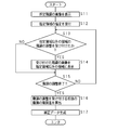
- FIG. 7 is a flowchart showing an example of a correction data generation processing procedure performed by the correction data generation apparatus 10 according to the present embodiment.
- the control unit 11 displays an image having a predetermined gradation (for example, a gray solid image) in the display area 1 of the display panel 30 (S11).
- the control unit 11 accepts designation of the designated area P (S12). In this case, the user can designate the designated area P by surrounding the area S where the luminance unevenness occurs using the drawing application. The control unit 11 determines whether or not the adjustment of the gradation of the region R other than the designated region P has been accepted (S13).
- the control unit 11 displays the received gradation image in the region R other than the designated region P (S14). Thereby, the user can confirm whether or not the luminance of the image after adjusting the gradation is equal to the luminance of the region S where the luminance unevenness occurs.
- the control unit 11 determines whether or not the gradation adjustment is finished (S15). Note that whether or not the gradation adjustment has been completed can be determined by a user operation.
- the control unit 11 performs the process of step S15 without performing the process of step S14.
- control unit 11 continues the processing from step S13.
- the control unit 11 calculates the gradation difference between the gradations before and after accepting the gradation adjustment (S16), and the correction data based on the calculated gradation difference. Is generated (S17), and the process is terminated.
- control unit 11 outputs the generated correction data to the display panel 30 so as to be stored in the memory 32 of the display panel 30. Thereby, the correction data can be written to the display panel 30. More specifically, the control unit 11 updates the luminance unevenness correction value stored at the address of the memory 32 specified by the specifying unit 17 with the correction value of the generated correction data.
- the process of accepting the gradation adjustment of the area R other than the designated area P in step S13 is illustrated, but the present invention is not limited to this, and the process of accepting the gradation adjustment of the designated area P Can also be done.
- the received gradation image may be displayed in the designated area P in step S14.
- the process shown in FIG. 7 may be performed a plurality of times for each area where color unevenness occurs.
- the correction data generation apparatus 10 can also be realized using a general-purpose computer including a CPU (processor), a RAM, and the like. That is, as shown in FIG. 7, a computer program that defines the procedure of each process is loaded into a RAM provided in the computer, and the computer program is executed by a CPU (processor), whereby the correction data generation device 10 is executed on the computer. Can be realized.
- the signal generation circuit 20 and the correction data generation device 10 have been described as separate devices. However, the present invention is not limited to this, and the signal generation circuit 20 is incorporated in the correction data generation device 10. There may be.
- a correction data generation apparatus is a correction data generation apparatus that generates correction data for correcting luminance unevenness in a display area of a display panel, and an image having a predetermined gradation is displayed in the display area.
- a display control unit that controls to display, a first reception unit that receives designation of a part of the designated area in the display area in a state where the image of the predetermined gradation is displayed in the display area, and the first reception
- a second reception unit that accepts the adjustment of the gradation of the image in either one of the designated region designated by the section or a region other than the designated region, and before and after the gradation reception is accepted by the second reception unit
- a generation unit that generates correction data based on the gradation difference calculated by the calculation unit.
- a computer program is a computer program for causing a computer to generate correction data for correcting luminance unevenness in a display area of a display panel.
- a display control unit that controls to display a tone image; a first reception unit that receives designation of a part of a designated area in the display area in a state where the image of the predetermined gradation is displayed in the display area;
- a second reception unit that receives the adjustment of the gradation of the image in either one of the designated designated area or an area other than the designated area, and calculates a gradation difference before and after the acceptance of the gradation adjustment. It functions as a calculation unit and a generation unit that generates correction data based on the calculated gradation difference.
- a correction data generation method is a correction data generation method performed by a correction data generation device that generates correction data for correcting luminance unevenness in a display area of a display panel.
- Control is performed to display an image of a predetermined gradation, and the designation of a part of the designated area in the display area is received in a state where the image of the predetermined gradation is displayed in the display area.
- Accepts gradation adjustment of the image in any one of the areas other than the designated area calculates gradation difference before and after acceptance of gradation adjustment, and corrects data based on the calculated gradation difference Is generated.
- the display control unit controls to display an image of a predetermined gradation in the display area of the display panel.
- the image having the predetermined gradation is, for example, an inspection image in which the gradation of all the pixels is the same.
- the predetermined gradation can be about 200, for example.
- the first accepting unit accepts designation of a part of the designated area in the display area in a state where an image having a predetermined gradation is displayed in the display area.
- an image with the same gradation of all pixels is displayed, if there is no uneven brightness of the display panel, the brightness of the display area is the same, but if the display panel has uneven brightness, the display area Among them, a region that is locally brighter than the surrounding region or a region that is locally darker than the surrounding region is generated.
- the designated area is, for example, a polygonal area surrounding a local area where luminance unevenness occurs.
- the designated area can be designated, for example, by operating a mouse, a keyboard, a touch panel, or the like using a drawing application.
- the second accepting unit accepts the adjustment of the gradation of the image in either the designated region designated by the first accepting unit or the region other than the designated region.
- the gradation is adjusted so that there is no difference in luminance between the designated area surrounding the area where the luminance unevenness occurs and the area other than the designated area. For example, if the brightness unevenness is darker than the surroundings, the image gradation may be adjusted to darken the surrounding brightness so that the brightness unevenness is eliminated, and the brightness unevenness area is brightened. The gradation may be adjusted. Also, if brightness unevenness occurs brighter than the surroundings, the image gradation may be adjusted to increase the surrounding brightness so that the brightness unevenness is eliminated, and the brightness unevenness area is darkened. The gradation may be adjusted.
- the generation unit generates correction data based on the gradation difference calculated by the calculation unit. For example, when the brightness unevenness is darker than the surroundings, the gradation difference calculated by the calculation unit when the gradation of the image is adjusted to darken the surrounding brightness so as to eliminate the brightness unevenness is, for example, -5, the correction data is generated so that the correction value for the region other than the designated region (the initial value when there is no correction is 0, for example) is -5. In this case, the correction value for the designated area is not changed. With the above configuration, luminance unevenness can be easily corrected without using an expensive imaging device.
- the display control unit is configured to adjust the level based on the adjustment amount received by the second reception unit when the second reception unit receives the adjustment of the gradation of the image.
- a tone image is displayed in the designated area or an area other than the designated area.
- the display control unit displays the gradation image based on the adjustment amount received by the second reception unit in the designated area or an area other than the designated area when the second reception unit accepts the adjustment of the gradation of the image.
- the gradation of the designated area is adjusted by an adjustment amount ⁇ x (for example, , 1, 2,%)
- the display control unit increases the gradation of the image displayed in the designated area by the adjustment amount ⁇ x.
- the adjustment amount ⁇ x for example, 1, 2,
- the display control unit adjusts the gradation of the image displayed in the area other than the designated area by the adjustment amount ⁇ x. Just make it bigger.
- the gradation can be adjusted with a simple operation so that luminance unevenness occurring in the display area is eliminated.
- the display control unit may include a plurality of pattern images having different gradations in the display area when the second reception unit receives adjustment of gradation of the image. And the second accepting unit accepts the gradation of the selected one of the plurality of pattern images as the adjusted gradation.
- the display control unit displays a plurality of pattern images having different gradations in the display area when the second reception unit accepts the adjustment of the gradation of the image.
- the second accepting unit accepts the gradation of the selected pattern image among the plurality of pattern images as the adjusted gradation.
- the display control unit When accepting the adjustment of gradation so that there is no difference in luminance between the designated area surrounding the area where luminance unevenness occurs and the area other than the designated area, the display control unit The pattern image is displayed in the display area.
- the gradation of each of the plurality of pattern images can be, for example, a required number of gradations among gradations that are equal to or higher than a predetermined gradation and lower than or equal to a predetermined gradation.
- the second reception unit receives the gradation of the selected pattern image as the adjusted gradation. That is, the difference between the gradation of the selected pattern image and the predetermined gradation is the gradation difference before and after accepting the adjustment of the gradation.
- the correction data generation apparatus further includes an output unit that outputs the correction data generated by the generation unit to the display panel.
- the output unit outputs the correction data generated by the generation unit to the display panel. Thereby, the correction data can be written on the display panel.
- the correction data includes a correction value of at least a luminance unevenness correction target pixel among the pixels constituting the display area
- the output unit includes the display panel.
- the correction data is output to the display panel in order to update the luminance unevenness correction value of each pixel constituting the display area stored in the storage unit included in the display unit with the correction value.
- the correction data includes at least a correction value of a pixel to be corrected for uneven brightness among the pixels constituting the display area.
- the display panel has a storage unit.
- the storage unit stores a luminance unevenness correction value of each pixel constituting the display area.
- the output unit outputs the correction data to the display panel so as to update the luminance unevenness correction value stored in the storage unit with the correction value included in the correction data.
- the luminance unevenness correction value of each pixel constituting the area can be updated. Further, when the gradation of the image in the designated area is adjusted so that the luminance unevenness is eliminated, the luminance unevenness correction value of each pixel constituting the designated area can be updated.
Landscapes
- Engineering & Computer Science (AREA)
- Physics & Mathematics (AREA)
- Computer Hardware Design (AREA)
- General Physics & Mathematics (AREA)
- Theoretical Computer Science (AREA)
- Control Of Indicators Other Than Cathode Ray Tubes (AREA)
- Liquid Crystal Display Device Control (AREA)
- Controls And Circuits For Display Device (AREA)
- Image Processing (AREA)
Abstract
簡便に輝度むらを補正することができる補正データ生成装置、コンピュータプログラム及び補正データ生成方法を提供する。 補正データ生成装置は、表示領域に所定階調の画像を表示すべく制御する表示制御部と、表示領域に所定階調の画像を表示させた状態で表示領域内の一部の指定領域の指定を受け付ける第1受付部と、第1受付部で指定された指定領域又は指定領域以外の領域のいずれか一方の領域での画像の階調の調整を受け付ける第2受付部と、第2受付部で階調の調整を受け付ける前後での階調差を算出する算出部と、算出部で算出した階調差に基づいて補正データを生成する生成部とを備える。
Description
本発明は、表示パネルの表示領域の輝度むらを補正するための補正データを生成する補正データ生成装置、該補正データ生成装置を実現するためのコンピュータプログラム及び補正データ生成方法に関する。
液晶ディスプレイ(LCD)、有機ELディスプレイ(OLED)等の表示装置では、製造工程上の種種の理由により、表示領域のある領域の画素の輝度が他の領域の画素の輝度よりも高くなる場合、あるいは低くなる場合が生じ、表示画面に明るい部分又は暗い部分が現れる輝度むらが発生することがある。
そこで、補正データ生成用データ作成装置が、検査用画像データに応じた画像を表示装置の表示画面に表示させている状態で、表示画面を撮像装置で撮像し、撮像結果に基づいて各ドット又は各微小エリアの輝度差を演算し、演算結果に応じて各ドット又は各微小エリアのγ値を個々に設定して、表示画面全体の輝度むらをなくす装置が開示されている(特許文献1参照)。
しかし、特許文献1の装置では、撮像装置で表示画面全体を撮像する必要がある。このため、表示装置の大型化に伴って、正確に輝度差を演算するためには、高価なレンズやカメラを備えた撮像装置等の設備が必要となり、大量の表示パネルの輝度むらを補正するためには、高価な設備を多数準備する必要がある。一方で、表示画面全体に及ばず、局所的に発生する軽微な輝度むらには、高価な設備を使用せずに簡易な手段で輝度むらを補正したという要望がある。
本発明は斯かる事情に鑑みてなされたものであり、簡便に輝度むらを補正することができる補正データ生成装置、該補正データ生成装置を実現するためのコンピュータプログラム及び補正データ生成方法を提供することを目的とする。
本発明の実施の形態に係る補正データ生成装置は、表示パネルの表示領域の輝度むらを補正するための補正データを生成する補正データ生成装置であって、前記表示領域に所定階調の画像を表示すべく制御する表示制御部と、前記表示領域に前記所定階調の画像を表示させた状態で前記表示領域内の一部の指定領域の指定を受け付ける第1受付部と、該第1受付部で指定された指定領域又は該指定領域以外の領域のいずれか一方の領域での前記画像の階調の調整を受け付ける第2受付部と、該第2受付部で階調の調整を受け付ける前後での階調差を算出する算出部と、該算出部で算出した階調差に基づいて補正データを生成する生成部とを備えることを特徴とする。
本発明の実施の形態に係るコンピュータプログラムは、コンピュータに、表示パネルの表示領域の輝度むらを補正するための補正データを生成させるためのコンピュータプログラムであって、コンピュータを、前記表示領域に所定階調の画像を表示すべく制御する表示制御部と、前記表示領域に前記所定階調の画像を表示させた状態で前記表示領域内の一部の指定領域の指定を受け付ける第1受付部と、指定された指定領域又は該指定領域以外の領域のいずれか一方の領域での前記画像の階調の調整を受け付ける第2受付部と、階調の調整を受け付ける前後での階調差を算出する算出部と、算出した階調差に基づいて補正データを生成する生成部として機能させることを特徴とする。
本発明の実施の形態に係る補正データ生成方法は、表示パネルの表示領域の輝度むらを補正するための補正データを生成する補正データ生成装置が行う補正データ生成方法であって、前記表示領域に所定階調の画像を表示すべく制御し、前記表示領域に前記所定階調の画像を表示させた状態で前記表示領域内の一部の指定領域の指定を受け付け、指定された指定領域又は該指定領域以外の領域のいずれか一方の領域での前記画像の階調の調整を受け付け、階調の調整を受け付ける前後での階調差を算出し、算出された階調差に基づいて補正データを生成することを特徴とする。
本発明によれば、簡便に輝度むらを補正することができる。
以下、本発明の実施の形態を図面に基づいて説明する。図1は本実施の形態の補正データ生成装置10の構成の一例を示すブロック図である。図1に示すように、補正データ生成装置10は、信号発生回路20を介して表示パネル30に接続されている。信号発生回路20は、補正データ生成装置10が出力する指令に基づいて、例えば、画像データ、及び画像を表示するための制御信号等を表示パネル30へ出力する。
表示パネル30は、表示領域1(表示画面)を有し、ソースドライバが実装されたソース基板31、ゲートドライバが実装されたゲート基板33が設けられている。また、ソース基板31にはメモリ32(記憶部)が実装されている。メモリ32は、表示領域1を構成する各画素の輝度むら補正値を記憶する。すなわち、メモリ32は、表示領域1を構成する各画素に対応させてアドレスを割り当て、それぞれのアドレスに対応する画素の輝度むら補正値を格納する補正テーブルのようなものとすることができる。
補正データ生成装置10は、装置全体を制御する制御部11、第1受付部12、第2受付部13、算出部14、生成部15、表示制御部16、及び特定部17などを備える。
表示制御部16は、表示パネル30の表示領域1に所定階調の画像を表示すべく制御する。所定階調の画像は、例えば、全画素の階調が同一の検査用の画像である。例えば、階調が0(黒)~255(白)の256段階である場合、所定階調は、例えば200程度とすることができるが、200に限定されるものではない。所定階調が200程度の場合、所定階調の画像は、グレーのべた画像となる。所定階調を、最大階調ではなく、200程度にすることにより、輝度むらが発生している領域が周囲の領域より明るい場合でも、輝度むらを視認しやすく表示させることができる。
第1受付部12は、例えば、マウス、キーボード又はタッチパネルなどのいずれかとすることができる。第1受付部12は、表示領域1に所定階調の画像(例えば、グレーのべた画像)を表示させた状態で表示領域1での指定領域の指定を受け付ける。
全画素の階調が同一のべた画像を表示させた場合に、表示パネル30に輝度むらがないときは、表示領域1の輝度は同じになる。しかし、表示パネル30に輝度むらがある場合には、表示領域1の中で周囲の領域に比べて局所的に明るい領域、又は周囲の領域に比べて局所的に暗い領域が発生する。指定領域は、例えば、輝度むらが発生している局所領域を囲む多角形のエリアである。指定領域は、例えば、補正データ生成装置10に内蔵の描画アプリケーションを用いて、第1受付部12を操作することにより指定することができる。
第2受付部13は、第1受付部12で指定された指定領域又は当該指定領域以外の領域のいずれか一方の領域での画像(例えば、グレーのべた画像)の階調の調整を受け付ける。階調の調整は、輝度むらが発生している領域を囲む指定領域と、当該指定領域以外の領域との輝度差がなくなるように行う。画像の階調の調整の詳細は後述する。第2受付部13は、例えば、階調を調整するためのツマミ、ボタン、スイッチ又はキーなどである。
また、表示制御部16は、第2受付部13で階調の調整を受け付けた場合、調整した階調の画像(べた画像)を表示領域1の指定領域又は当該指定領域以外の領域のいずれか一方の領域に表示する。なお、表示制御部16は、表示領域1の指定領域以外の領域の全部に調整した階調の画像を表示してもよく、あるいは、表示領域1の指定領域以外の領域の一部だけに調整した階調の画像を表示してもよい。
算出部14は、第2受付部13で画像の階調の調整を受け付ける前後での階調差を算出する。例えば、階調の調整を受け付ける前の画像(例えば、グレーのべた画像)の階調を200とし、階調の調整を受け付けた後の画像の階調を195とすると、階調差は-5(=195-200)となる。
生成部15は、算出部14で算出した階調差に基づいて補正データを生成する。補正データは、表示領域1を構成する各画素のうち少なくとも輝度むらの補正対象の画素の補正値を含む。例えば、周囲よりも暗い輝度むらが発生している場合、輝度むらがなくなるように周囲の輝度を暗くするように画像(例えば、グレーのべた画像)の階調を調整したときに、算出部14で算出した階調差が、例えば、-5とすると、指定領域以外の領域を構成する各画素の補正値(補正なしのときの初期値を、例えば、0とする)が、-5となるように補正データを生成する。なお、この場合、指定領域を構成する各画素の補正値は変更しない。
また、周囲よりも暗い輝度むらが発生している場合、輝度むらがなくなるように周囲の輝度を暗くするように画像(例えば、グレーのべた画像)の階調を調整したときに、算出部14で算出した階調差が、例えば、-5とすると、指定領域以外の領域を構成する各画素の階調を補正する代わりに、指定領域を構成する各画素の階調を補正してもよい。この場合、指定領域を構成する各画素の補正値が、+5となるように補正データを生成すればよい。なお、この場合、指定領域以外の領域を構成する各画素の補正値は変更しない。
上述の構成により、高価な撮像装置を用いることなく、簡易に輝度むらを補正することができる。
なお、本実施の形態では、表示パネル30のメモリ32に記憶されたデータを「輝度むら補正値」と称し、生成部15が生成する補正データに含まれるデータを「補正値」と称して、両者を区別する。すなわち、メモリ32に記憶される前のデータが「補正値」であり、メモリ32に記憶したデータが「輝度むら補正値」である。
次に、本実施の形態の補正データ生成装置10による補正データの生成方法について説明する。
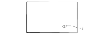
図2A、図2B及び図2Cは本実施の形態の補正データ生成装置10による輝度むら補正の第1例を示す模式図である。図2は、輝度むら補正を行う場合の所定階調の画像の階調の調整の一例を示す。図2Aは、表示パネル30の表示領域1に所定階調の画像(例えば、グレーのべた画像)を表示させた状態を示す。図2Aにおいて、符号Sで示す領域は、周囲の領域よりも輝度が暗い領域であり、輝度むらが発生している領域である。
図2Bは、第1受付部12を操作することにより、指定領域Pを指定した状態を示す。例えば、ユーザは、表示パネル30の表示領域1に発生した輝度むら(図2Aの符号Sで示す領域)を囲むように、例えば、多角形の枠を描画することにより、多角形の指定領域Pを指定することができる。指定領域Pは、多角形に限定されない。なお、表示領域1のうち、指定領域P以外の領域を符号Rで表す。
次に、表示制御部16は、第2受付部13が画像の階調の調整を受け付ける際、第2受付部13が受け付けた調整量に基づく階調の画像を指定領域P又は該指定領域P以外の領域Rに表示する。
例えば、輝度むらが発生している領域を囲む指定領域Pと、当該指定領域P以外の領域Rとの輝度差がなくなるように階調の調整を受け付ける際に、指定領域Pの階調を調整量Δx(例えば、1、2、…など)だけ大きくした場合、表示制御部16は、指定領域Pに表示する画像の階調を調整量Δxだけ大きくする。また、指定領域P以外の領域Rの階調を調整量Δx(例えば、1、2、…など)だけ大きくした場合、表示制御部16は、指定領域P以外の領域Rに表示する画像の階調を調整量Δxだけ大きくする。画像の階調を調整量Δxだけ小さくする場合も同様である。
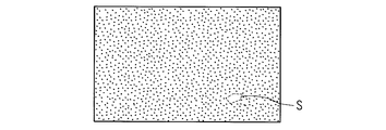
例えば、第2受付部13を操作することにより、領域Rの輝度が指定領域Pの輝度に近づくように、領域Rでの画像の階調を調整する。この場合、領域Rの輝度を下げて、領域Rを少し暗くするので、領域Rでの画像の階調を徐々に小さくする。例えば、階調を1ずつ小さくすることができる。なお、指定領域Pでの画像の階調は変更しない。図2Cは、領域Rの輝度と指定領域Pの輝度が同等になった状態を示す。図2Cの状態で、領域Rでの画像の階調の調整は終了する。なお、図2では、分かりやすくするため、輝度の差を大きく描いている。
上述の構成により、表示領域1に生じている輝度むらがなくなるように簡便な操作で階調の調整を行うことができる。
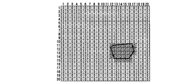
図3A、図3B及び図3Cは本実施の形態の補正データ生成装置10による補正データの生成の第1例を示す模式図である。図3は、輝度むら補正を行う場合の補正データの生成過程の一例を示す。図3では、簡便のため表示領域1を構成する各画素を、20画素×20画素の画素ブロックで示す。この場合、補正データは、400個(20×20)の補正値を含む。図3A、図3B及び図3Cの状態は、それぞれ図2A、図2B及び図2Cに対応する。
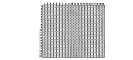
図3Aは、図2Aで示したように、表示パネル30の表示領域1に所定階調の画像(例えば、グレーのべた画像)を表示させた状態で、輝度むら補正を行う前の表示領域1を構成する各画素の補正値を示し、便宜上、すべての画素に0が割り当てられている。
図3Bは、図2Bで示したように、指定領域Pが指定された状態であり、指定領域Pを構成する画素を枠で囲んで示す。図3Bは指定領域Pと指定領域P以外の領域Rそれぞれを構成する各画素を区別して表示している。
図3Cは、図2Cで示したように、領域Rでの画像の階調の調整が終了した状態を示す。図3Cに示すように、この例では、領域Rでの画像の階調を5だけ下げることにより、領域Rの画素の輝度と指定領域Pの画素の輝度とが同等になる。図3Cは、輝度むら補正を行った後の表示領域1を構成する各画素の補正値を示し、最終的に生成された補正データを示す。
なお、図2及び図3の例では、算出部14は、第2受付部13で画像の階調の調整を受け付ける前後での階調差として、-5を算出することになる。
制御部10は、出力部としての機能を有し、生成部15で生成した補正データを表示パネル30へ出力する。これにより、表示パネル30に生成部15で生成した補正データを書き込むことができる。
より具体的には、制御部10は、表示パネル30のメモリ32に記憶された輝度むら補正値を、生成部15で生成した補正データに含まれる補正値で更新すべく補正データを表示パネル30へ出力する。
表示パネル30のメモリ32に記憶された輝度むら補正値の更新は、例えば、以下のように行うことができる。図1に示す、特定部17は、第1受付部12で指定された指定領域Pに基づいて、メモリ32での指定領域P又は当該指定領域P以外の領域Rに対応するアドレスを特定する。例えば、図2及び図3で示したように、指定領域P以外の領域Rでの画像の階調を調整する場合には、特定部17は、メモリ32の当該領域Rに対応するアドレスを特定する。すなわち、特定部17は、図3に例示した20画素×20画素のうちの領域Rの各画素に対応するメモリ32のアドレスを特定する。
制御部11は、特定部17で特定したアドレスに記憶した輝度むら補正値を、生成部15で生成した補正データに含まれる補正値で更新する。
上述のように、輝度むらがなくなるように指定領域P以外の領域Rでの画像の階調を調整した場合には、メモリ32の当該領域Rに対応するアドレスに格納された輝度むら補正値を更新することができる。また、高価な撮像装置を用いることなく、簡易に輝度むらを補正することができる。
図2及び図3の例では、領域Rでの画像の階調を小さくして、領域Rの輝度を下げる構成であったが、これに限定されるものではない。例えば、指定領域Pでの画像の階調を大きくして、指定領域Pの輝度を上げるようにしてもよい。この場合には、指定領域Pでの画像の階調が調整されたので、特定部17は、メモリ32の指定領域Pに対応するアドレスを特定する。
例えば、第2受付部13で画像の階調の調整を受け付ける前後での階調差を、5とすると、図3Cにおいて、-5が格納されている箇所には、0が格納され、図3Cにおいて、0が格納されている箇所には、5が格納される。これにより、輝度むらがなくなるように指定領域Pでの画像の階調を調整した場合には、メモリ32の当該指定領域Pに対応するアドレスに格納された輝度むら補正値を更新することができる。
図4A、図4B及び図4Cは本実施の形態の補正データ生成装置10による輝度むら補正の第2例を示す模式図である。図4は、輝度むら補正を行う場合の所定階調の画像の階調の調整の一例を示す。図4Aにおいて、符号Sで示す領域は、周囲の領域よりも輝度が明るい領域であり、輝度むらが発生していることを示す。
図4Bは、図2Bと同様、第1受付部12を操作することにより、指定領域Pを指定した状態を示す。例えば、ユーザは、表示パネル30の表示領域1に発生した輝度むら(図4Aの符号Sで示す領域)を囲むように、例えば、多角形の枠を描画することにより、多角形の指定領域Pを指定することができる。なお、表示領域1のうち、指定領域P以外の領域を符号Rで表す。
次に、第2受付部13を操作することにより、領域Rの輝度が指定領域Pの輝度に近づくように、領域Rでの画像の階調を調整する。この場合、領域Rの輝度を上げて、領域Rを少し明るくするので、領域Rでの画像の階調を徐々に大きくする。例えば、階調を1ずつ大きくすることができる。なお、指定領域Pでの画像の階調は変更しない。図4Cは、領域Rの輝度と指定領域Pの輝度が同等になった状態を示す。図4Cの状態で、領域Rでの画像の階調の調整は終了する。
図4の場合も図2の場合と同様に、表示領域1に生じている輝度むらがなくなるように簡便な操作で階調の調整を行うことができる。
図5A、図5B及び図5Cは本実施の形態の補正データ生成装置10による補正データの生成の第2例を示す模式図である。図5は、図3の場合と同様、輝度むら補正を行う場合の補正データの生成過程の一例を示す。図5では、簡便のため表示領域1を構成する各画素を、20画素×20画素の画素ブロックで示す。この場合、補正データは、400個(20×20)の補正値を含む。図5A、図5B及び図5Cの状態は、それぞれ図4A、図4B及び図4Cに対応する。
図5Aは、図4Aで示したように、表示パネル30の表示領域1に所定階調の画像(例えば、グレーのべた画像)を表示させた状態で、輝度むら補正を行う前の表示領域1を構成する各画素の補正値を示し、便宜上、すべての画素に0が割り当てられている。
図5Bは、図4Bで示したように、指定領域Pが指定された状態であり、指定領域Pを構成する画素を枠で囲んで示す。図5Bは指定領域Pと指定領域P以外の領域Rそれぞれを構成する各画素を区別して表示している。
図5Cは、図4Cで示したように、領域Rでの画像の階調の調整が終了した状態を示す。図5Cに示すように、この例では、領域Rでの画像の階調を5だけ上げることにより、領域Rの画素の輝度と指定領域Pの画素の輝度とが同等になる。図5Cは、輝度むら補正を行った後の表示領域1を構成する各画素の補正値を示し、最終的に生成された補正データを示す。
なお、図4及び図5の例では、算出部14は、第2受付部13で画像の階調の調整を受け付ける前後での階調差として、5を算出することになる。
図4及び図5の例の場合も図2及び図3の例の場合と同様に、制御部10は、生成部15で生成した補正データを表示パネル30へ出力する。これにより、表示パネル30に生成部15で生成した補正データを書き込むことができる。
上述のように、輝度むらがなくなるように指定領域P以外の領域Rでの画像の階調を調整した場合には、メモリ32の当該領域Rに対応するアドレスに格納された輝度むら補正値を更新することができる。また、高価な撮像装置を用いることなく、簡易に輝度むらを補正することができる。
図4及び図5の例では、領域Rでの画像の階調を大きくして、領域Rの輝度を上げる構成であったが、これに限定されるものではない。例えば、指定領域Pでの画像の階調を小さくして、指定領域Pの輝度を下げるようにしてもよい。この場合には、指定領域Pでの画像の階調が調整されたので、特定部17は、メモリ32の指定領域Pに対応するアドレスを特定する。
例えば、第2受付部13で画像の階調の調整を受け付ける前後での階調差を、5とすると、図5Cにおいて、5が格納されている箇所には、0が格納され、図5Cにおいて、0が格納されている箇所には、-5が格納される。これにより、輝度むらがなくなるように指定領域Pでの画像の階調を調整した場合には、メモリ32の当該指定領域Pに対応するアドレスに格納された輝度むら補正値を更新することができる。
上述の例では、第2受付部は、階調を調整するためのツマミ、ボタン、スイッチ又はキーなどであり、階調を1ずつ増加又は減少させる構成であったが、これに限定されるものではなく、階調の調整用のパターン画像を表示させることもできる。
図6は本実施の形態の補正データ生成装置10による階調の調整方法の一例を示す模式図である。図6に示す調整方法では、表示制御部16は、第2受付部13が画像の階調の調整を受け付ける際、階調の異なる複数のパターン画像2を表示領域1に表示する。この場合、第2受付部13は、複数のパターン画像2のうちの選択された一のパターン画像2の階調を調整後の階調として受け付ける。
例えば、輝度むらが発生している領域を囲む指定領域Pと、当該指定領域P以外の領域Rとの輝度差がなくなるように階調の調整を受け付ける際に、図6に示すように、表示制御部16は、階調の異なる複数のパターン画像2を表示領域1(図6の例では、領域R)に表示する。複数のパターン画像2それぞれの階調は、例えば、所定階調より小さい階調以上であって、所定階調より大きい階調以下の階調のうち所要の数の階調を用いることができる。
ユーザは、表示された各パターン画像2の輝度と指定領域Pの輝度とを比較して、輝度が最も近いパターン画像2を選択することにより、指定領域Pの輝度と同程度の輝度のパターン画像2が選択される。そして、第2受付部13は、選択されたパターン画像2の階調を調整後の階調として受け付ける。すなわち、選択されたパターン画像2の階調と所定階調との差が、階調の調整を受け付ける前後での階調差となる。
上述の構成により、階調を1ずつ変化させる必要がないので、表示領域1に生じている輝度むらがなくなるように、階調の調整を高速かつ簡便に行うことができる。
次に、本実施の形態の補正データ生成装置10の動作について説明する。図7は本実施の形態の補正データ生成装置10による補正データ生成の処理手順の一例を示すフローチャートである。以下では、便宜上、処理の主体を制御部11として説明する。制御部11は、所定階調の画像(例えば、グレーのべた画像)を表示パネル30の表示領域1に表示する(S11)。
制御部11は、指定領域Pの指定を受け付ける(S12)。この場合、ユーザは、描画アプリケーションを用いて、輝度むらが発生している領域Sを囲むことにより、指定領域Pを指定することができる。制御部11は、指定領域P以外の領域Rの階調の調整を受け付けたか否かを判定する(S13)。
階調の調整を受け付けた場合(S13でYES)、制御部11は、受け付けた階調の画像を指定領域P以外の領域Rに表示する(S14)。これにより、ユーザは、階調を調整した後の画像の輝度が、輝度むらが発生している領域Sの輝度と同等になったか否かを確認することができる。制御部11は、階調の調整が終了したか否かを判定する(S15)。なお、階調の調整が終了したか否かは、ユーザの操作により判定することができる。階調の調整を受け付けていない場合(S13でNO)、制御部11は、ステップS14の処理を行うことなく、ステップS15の処理を行う。
階調の調整が終了していない場合(S15でNO)、制御部11は、ステップS13以降の処理を続ける。階調の調整が終了した場合(S15でYES)、制御部11は、階調の調整を受け付ける前後の階調の階調差を算出し(S16)、算出した階調差に基づいて補正データを生成し(S17)、処理を終了する。
なお、図7には図示していないが、制御部11は、生成した補正データを表示パネル30のメモリ32に記憶すべく表示パネル30へ出力する。これにより、表示パネル30に補正データを書き込むことができる。より具体的には、制御部11は、特定部17で特定したメモリ32のアドレスに記憶した輝度むら補正値を、生成した補正データの補正値で更新する。
図7の例では、ステップS13において、指定領域P以外の領域Rの階調の調整を受け付ける処理を例示したが、これに限定されるものではなく、指定領域Pの階調の調整を受け付ける処理を行うこともできる。この場合、ステップS14において、受け付けた階調の画像を指定領域Pに表示すればよい。
なお、表示領域1に色むらが発生している領域が複数存在する場合には、図7に示す処理を、色むらが発生している領域毎に複数回行えばよい。
本実施の形態の補正データ生成装置10は、CPU(プロセッサ)、RAMなどを備えた汎用コンピュータを用いて実現することもできる。すなわち、図7に示すような、各処理の手順を定めたコンピュータプログラムをコンピュータに備えられたRAMにロードし、コンピュータプログラムをCPU(プロセッサ)で実行することにより、コンピュータ上で補正データ生成装置10を実現することができる。
上述の実施の形態では、信号発生回路20と補正データ生成装置10とは別個の装置として説明したが、これに限定されるものではなく、補正データ生成装置10に信号発生回路20を組み込む構成であってもよい。
また、上述の各実施例において記載されている構成は、お互いに組み合わせることが可能であり、組み合わせをすることにより、新しい技術的特徴を形成することができる。
本発明の実施の形態に係る補正データ生成装置は、表示パネルの表示領域の輝度むらを補正するための補正データを生成する補正データ生成装置であって、前記表示領域に所定階調の画像を表示すべく制御する表示制御部と、前記表示領域に前記所定階調の画像を表示させた状態で前記表示領域内の一部の指定領域の指定を受け付ける第1受付部と、該第1受付部で指定された指定領域又は該指定領域以外の領域のいずれか一方の領域での前記画像の階調の調整を受け付ける第2受付部と、該第2受付部で階調の調整を受け付ける前後での階調差を算出する算出部と、該算出部で算出した階調差に基づいて補正データを生成する生成部とを備えることを特徴とする。
本発明の実施の形態に係るコンピュータプログラムは、コンピュータに、表示パネルの表示領域の輝度むらを補正するための補正データを生成させるためのコンピュータプログラムであって、コンピュータを、前記表示領域に所定階調の画像を表示すべく制御する表示制御部と、前記表示領域に前記所定階調の画像を表示させた状態で前記表示領域内の一部の指定領域の指定を受け付ける第1受付部と、指定された指定領域又は該指定領域以外の領域のいずれか一方の領域での前記画像の階調の調整を受け付ける第2受付部と、階調の調整を受け付ける前後での階調差を算出する算出部と、算出した階調差に基づいて補正データを生成する生成部として機能させることを特徴とする。
本発明の実施の形態に係る補正データ生成方法は、表示パネルの表示領域の輝度むらを補正するための補正データを生成する補正データ生成装置が行う補正データ生成方法であって、前記表示領域に所定階調の画像を表示すべく制御し、前記表示領域に前記所定階調の画像を表示させた状態で前記表示領域内の一部の指定領域の指定を受け付け、指定された指定領域又は該指定領域以外の領域のいずれか一方の領域での前記画像の階調の調整を受け付け、階調の調整を受け付ける前後での階調差を算出し、算出された階調差に基づいて補正データを生成することを特徴とする。
表示制御部は、表示パネルの表示領域に所定階調の画像を表示すべく制御する。所定階調の画像は、例えば、全画素の階調が同一の検査用の画像である。例えば、階調が0(黒)~255(白)の256段階である場合、所定階調は、例えば200程度とすることができる。
第1受付部は、表示領域に所定階調の画像を表示させた状態で表示領域内の一部の指定領域の指定を受け付ける。全画素の階調が同一の画像を表示させた場合に、表示パネルの輝度むらがないときは、表示領域の輝度は同じになるが、表示パネルに輝度むらがある場合には、表示領域の中で周囲の領域に比べて局所的に明るい領域、又は周囲の領域に比べて局所的に暗い領域が発生する。指定領域は、例えば、輝度むらが発生している局所領域を囲む多角形のエリアである。指定領域は、例えば、描画アプリケーションを用いて、マウス、キーボード又はタッチパネルなどを操作することにより指定することができる。
第2受付部は、第1受付部で指定された指定領域又は当該指定領域以外の領域のいずれか一方の領域での画像の階調の調整を受け付ける。階調の調整は、輝度むらが発生している領域を囲む指定領域と、当該指定領域以外の領域との輝度差がなくなるように行う。例えば、周囲よりも暗い輝度むらが発生している場合、輝度むらがなくなるように周囲の輝度を暗くするように画像の階調を調整してもよく、輝度むらの領域を明るくするように画像の階調を調整してもよい。また、周囲よりも明るい輝度むらが発生している場合、輝度むらがなくなるように周囲の輝度を明るくするように画像の階調を調整してもよく、輝度むらの領域を暗くするように画像の階調を調整してもよい。
算出部は、第2受付部で調整を受け付ける前後での階調差を算出する。例えば、階調の調整を受け付ける前の画像の階調を200とし、階調の調整を受け付けた後の画像の階調を195とすると、階調差は-5(=195-200)となる。
生成部は、算出部で算出した階調差に基づいて補正データを生成する。例えば、周囲よりも暗い輝度むらが発生している場合、輝度むらがなくなるように周囲の輝度を暗くするように画像の階調を調整したときに、算出部で算出した階調差が、例えば、-5とすると、指定領域以外の領域に対する補正値(補正なしのときの初期値を、例えば、0とする)が、-5となるように補正データを生成する。なお、この場合、指定領域に対する補正値は変更しない。上述の構成により、高価な撮像装置を用いることなく、簡易に輝度むらを補正することができる。
本発明の実施の形態に係る補正データ生成装置は、前記表示制御部は、前記第2受付部が前記画像の階調の調整を受け付ける際、前記第2受付部が受け付けた調整量に基づく階調の画像を前記指定領域又は該指定領域以外の領域に表示することを特徴とする。
表示制御部は、第2受付部が画像の階調の調整を受け付ける際、第2受付部が受け付けた調整量に基づく階調の画像を指定領域又は該指定領域以外の領域に表示する。
例えば、輝度むらが発生している領域を囲む指定領域と、当該指定領域以外の領域との輝度差がなくなるように階調の調整を受け付ける際に、指定領域の階調を調整量Δx(例えば、1、2、…など)だけ大きくした場合、表示制御部は、指定領域に表示する画像の階調を調整量Δxだけ大きくする。また、指定領域以外の領域の階調を調整量Δx(例えば、1、2、…など)だけ大きくした場合、表示制御部は、指定領域以外の領域に表示する画像の階調を調整量Δxだけ大きくする。
上述の構成により、表示領域に生じている輝度むらがなくなるように簡便な操作で階調の調整を行うことができる。
本発明の実施の形態に係る補正データ生成装置は、前記表示制御部は、前記第2受付部が前記画像の階調の調整を受け付ける際、階調の異なる複数のパターン画像を前記表示領域に表示し、前記第2受付部は、前記複数のパターン画像のうちの選択された一のパターン画像の階調を調整後の階調として受け付けることを特徴とする。
表示制御部は、第2受付部が画像の階調の調整を受け付ける際、階調の異なる複数のパターン画像を表示領域に表示する。第2受付部は、複数のパターン画像のうちの選択された一のパターン画像の階調を調整後の階調として受け付ける。
例えば、輝度むらが発生している領域を囲む指定領域と、当該指定領域以外の領域との輝度差がなくなるように階調の調整を受け付ける際に、表示制御部は、階調の異なる複数のパターン画像を表示領域に表示する。複数のパターン画像それぞれの階調は、例えば、所定階調より小さい階調以上であって、所定階調より大きい階調以下の階調のうち所要の数の階調を用いることができる。ユーザが、例えば、指定領域の輝度と同程度の輝度のパターン画像を選択すると、第2受付部は、選択されたパターン画像の階調を調整後の階調として受け付ける。すなわち、選択されたパターン画像の階調と所定階調との差が、階調の調整を受け付ける前後での階調差となる。
上述の構成により、表示領域に生じている輝度むらがなくなるように簡便な操作、かつ高速に階調の調整を行うことができる。
本発明の実施の形態に係る補正データ生成装置は、前記生成部で生成した補正データを前記表示パネルへ出力する出力部をさらに備えることを特徴とする。
出力部は、生成部で生成した補正データを表示パネルへ出力する。これにより、表示パネルに補正データを書き込むことができる。
本発明の実施の形態に係る補正データ生成装置は、前記補正データは、前記表示領域を構成する各画素のうち少なくとも輝度むら補正対象の画素の補正値を含み、前記出力部は、前記表示パネルが有する記憶部に記憶された前記表示領域を構成する各画素の輝度むら補正値を前記補正値で更新すべく前記補正データを前記表示パネルへ出力する。
補正データは、表示領域を構成する各画素のうち少なくとも輝度むら補正対象の画素の補正値を含む。表示パネルは、記憶部を有する。記憶部は、表示領域を構成する各画素の輝度むら補正値を記憶する。そして、出力部は、記憶部に記憶された輝度むら補正値を補正データに含まれる補正値で更新すべく補正データを表示パネルへ出力する。
これにより、例えば、輝度むらがなくなるように指定領域以外の領域での画像の階調を調整した場合には、当該領域を構成する各画素の輝度むら補正値を更新することができる。また、輝度むらがなくなるように指定領域での画像の階調を調整した場合には、当該指定領域を構成する各画素の輝度むら補正値を更新することができる。
1 表示領域
10 補正データ生成装置
11 制御部
12 第1受付部
13 第2受付部
14 算出部
15 生成部
16 表示制御部
17 特定部
30 表示パネル
32 メモリ
10 補正データ生成装置
11 制御部
12 第1受付部
13 第2受付部
14 算出部
15 生成部
16 表示制御部
17 特定部
30 表示パネル
32 メモリ
Claims (7)
- 表示パネルの表示領域の輝度むらを補正するための補正データを生成する補正データ生成装置であって、
前記表示領域に所定階調の画像を表示すべく制御する表示制御部と、
前記表示領域に前記所定階調の画像を表示させた状態で前記表示領域内の一部の指定領域の指定を受け付ける第1受付部と、
該第1受付部で指定された指定領域又は該指定領域以外の領域のいずれか一方の領域での前記画像の階調の調整を受け付ける第2受付部と、
該第2受付部で階調の調整を受け付ける前後での階調差を算出する算出部と、
該算出部で算出した階調差に基づいて補正データを生成する生成部と
を備えることを特徴とする補正データ生成装置。 - 前記表示制御部は、
前記第2受付部が前記画像の階調の調整を受け付ける際、前記第2受付部が受け付けた調整量に基づく階調の画像を前記指定領域又は該指定領域以外の領域に表示することを特徴とする請求項1に記載の補正データ生成装置。 - 前記表示制御部は、
前記第2受付部が前記画像の階調の調整を受け付ける際、階調の異なる複数のパターン画像を前記表示領域に表示し、
前記第2受付部は、
前記複数のパターン画像のうちの選択された一のパターン画像の階調を調整後の階調として受け付けることを特徴とする請求項1に記載の補正データ生成装置。 - 前記生成部で生成した補正データを前記表示パネルへ出力する出力部をさらに備えることを特徴とする請求項1から請求項3までのいずれか1項に記載の補正データ生成装置。
- 前記補正データは、
前記表示領域を構成する各画素のうち少なくとも輝度むら補正対象の画素の補正値を含み、
前記出力部は、
前記表示パネルが有する記憶部に記憶された前記表示領域を構成する各画素の輝度むら補正値を前記補正値で更新すべく前記補正データを前記表示パネルへ出力する請求項4に記載の補正データ生成装置。 - コンピュータに、表示パネルの表示領域の輝度むらを補正するための補正データを生成させるためのコンピュータプログラムであって、
コンピュータを、
前記表示領域に所定階調の画像を表示すべく制御する表示制御部と、
前記表示領域に前記所定階調の画像を表示させた状態で前記表示領域内の一部の指定領域の指定を受け付ける第1受付部と、
指定された指定領域又は該指定領域以外の領域のいずれか一方の領域での前記画像の階調の調整を受け付ける第2受付部と、
階調の調整を受け付ける前後での階調差を算出する算出部と、
算出した階調差に基づいて補正データを生成する生成部と
して機能させることを特徴とするコンピュータプログラム。 - 表示パネルの表示領域の輝度むらを補正するための補正データを生成する補正データ生成装置が行う補正データ生成方法であって、
前記表示領域に所定階調の画像を表示すべく制御し、
前記表示領域に前記所定階調の画像を表示させた状態で前記表示領域内の一部の指定領域の指定を受け付け、
指定された指定領域又は該指定領域以外の領域のいずれか一方の領域での前記画像の階調の調整を受け付け、
階調の調整を受け付ける前後での階調差を算出し、
算出された階調差に基づいて補正データを生成することを特徴とする補正データ生成方法。
Priority Applications (3)
| Application Number | Priority Date | Filing Date | Title |
|---|---|---|---|
| PCT/JP2016/061917 WO2017179155A1 (ja) | 2016-04-13 | 2016-04-13 | 補正データ生成装置、コンピュータプログラム及び補正データ生成方法 |
| US16/093,335 US20190130811A1 (en) | 2016-04-13 | 2016-04-13 | Correction data generation device, computer program, and method for generating correction data |
| CN201680086653.3A CN109313882A (zh) | 2016-04-13 | 2016-04-13 | 校正数据生成装置、计算机程序以及校正数据生成方法 |
Applications Claiming Priority (1)
| Application Number | Priority Date | Filing Date | Title |
|---|---|---|---|
| PCT/JP2016/061917 WO2017179155A1 (ja) | 2016-04-13 | 2016-04-13 | 補正データ生成装置、コンピュータプログラム及び補正データ生成方法 |
Publications (1)
| Publication Number | Publication Date |
|---|---|
| WO2017179155A1 true WO2017179155A1 (ja) | 2017-10-19 |
Family
ID=60042094
Family Applications (1)
| Application Number | Title | Priority Date | Filing Date |
|---|---|---|---|
| PCT/JP2016/061917 Ceased WO2017179155A1 (ja) | 2016-04-13 | 2016-04-13 | 補正データ生成装置、コンピュータプログラム及び補正データ生成方法 |
Country Status (3)
| Country | Link |
|---|---|
| US (1) | US20190130811A1 (ja) |
| CN (1) | CN109313882A (ja) |
| WO (1) | WO2017179155A1 (ja) |
Families Citing this family (6)
| Publication number | Priority date | Publication date | Assignee | Title |
|---|---|---|---|---|
| US11355083B2 (en) * | 2018-06-13 | 2022-06-07 | Shenzhen Torey Microelectronic Technology Co. Ltd. | Correction device, display device, method of performing correction for display device, and method of manufacturing display device |
| US12451101B2 (en) | 2019-04-10 | 2025-10-21 | Hefei Reliance Memory Limited | Display driver system with embedded non-volatile memory |
| US11557264B2 (en) * | 2019-04-10 | 2023-01-17 | Hefei Reliance Memory Limited | Display driver system with embedded non-volatile memory |
| KR102882555B1 (ko) | 2019-09-12 | 2025-11-06 | 허페이 릴라이언스 메모리 리미티드 | 임베디드 저항성 랜덤 액세스 메모리를 갖는 디스플레이 드라이버 집적 회로 및 이를 포함하는 디스플레이 디바이스 |
| GB2595732B (en) * | 2020-06-05 | 2025-02-26 | Displaylink Uk Ltd | Managing display data |
| CN118571188B (zh) * | 2024-06-20 | 2025-12-09 | Tcl华星光电技术有限公司 | 显示面板的亮度校正方法及亮度校正装置 |
Citations (7)
| Publication number | Priority date | Publication date | Assignee | Title |
|---|---|---|---|---|
| JPH0431120U (ja) * | 1990-07-10 | 1992-03-12 | ||
| JPH07261719A (ja) * | 1994-03-24 | 1995-10-13 | Semiconductor Energy Lab Co Ltd | 表示装置の補正システムおよびその動作方法 |
| JP2004062068A (ja) * | 2002-07-31 | 2004-02-26 | Matsushita Electric Ind Co Ltd | 映像表示装置 |
| JP2005250265A (ja) * | 2004-03-05 | 2005-09-15 | Dainippon Printing Co Ltd | カラーモニタのキャリブレーション及び/またはプロファイル作成の方法及び装置 |
| JP2006113090A (ja) * | 2004-10-12 | 2006-04-27 | Seiko Epson Corp | 電気光学装置用画像補正装置及び方法、画像補正装置付き電気光学装置、並びに電子機器 |
| JP2006186662A (ja) * | 2004-12-27 | 2006-07-13 | Toshiba Corp | 投射型画像表示装置および同装置の色補正方法 |
| JP2008058506A (ja) * | 2006-08-30 | 2008-03-13 | Casio Hitachi Mobile Communications Co Ltd | 電子機器およびプログラム |
Family Cites Families (4)
| Publication number | Priority date | Publication date | Assignee | Title |
|---|---|---|---|---|
| JP5971973B2 (ja) * | 2012-02-21 | 2016-08-17 | キヤノン株式会社 | 投影装置 |
| CN103377624B (zh) * | 2012-04-17 | 2016-05-18 | 宇龙计算机通信科技(深圳)有限公司 | 一种调节亮度的方法及装置 |
| CN102707883B (zh) * | 2012-04-28 | 2016-08-17 | 深圳Tcl新技术有限公司 | 图标智能显示的方法和装置 |
| JP5922160B2 (ja) * | 2014-01-30 | 2016-05-24 | シャープ株式会社 | 表示較正システム、プログラム、記録媒体 |
-
2016
- 2016-04-13 WO PCT/JP2016/061917 patent/WO2017179155A1/ja not_active Ceased
- 2016-04-13 US US16/093,335 patent/US20190130811A1/en not_active Abandoned
- 2016-04-13 CN CN201680086653.3A patent/CN109313882A/zh active Pending
Patent Citations (7)
| Publication number | Priority date | Publication date | Assignee | Title |
|---|---|---|---|---|
| JPH0431120U (ja) * | 1990-07-10 | 1992-03-12 | ||
| JPH07261719A (ja) * | 1994-03-24 | 1995-10-13 | Semiconductor Energy Lab Co Ltd | 表示装置の補正システムおよびその動作方法 |
| JP2004062068A (ja) * | 2002-07-31 | 2004-02-26 | Matsushita Electric Ind Co Ltd | 映像表示装置 |
| JP2005250265A (ja) * | 2004-03-05 | 2005-09-15 | Dainippon Printing Co Ltd | カラーモニタのキャリブレーション及び/またはプロファイル作成の方法及び装置 |
| JP2006113090A (ja) * | 2004-10-12 | 2006-04-27 | Seiko Epson Corp | 電気光学装置用画像補正装置及び方法、画像補正装置付き電気光学装置、並びに電子機器 |
| JP2006186662A (ja) * | 2004-12-27 | 2006-07-13 | Toshiba Corp | 投射型画像表示装置および同装置の色補正方法 |
| JP2008058506A (ja) * | 2006-08-30 | 2008-03-13 | Casio Hitachi Mobile Communications Co Ltd | 電子機器およびプログラム |
Also Published As
| Publication number | Publication date |
|---|---|
| CN109313882A (zh) | 2019-02-05 |
| US20190130811A1 (en) | 2019-05-02 |
Similar Documents
| Publication | Publication Date | Title |
|---|---|---|
| CN109658877B (zh) | 一种显示装置及其驱动方法以及电子设备 | |
| US10748467B2 (en) | Display panel, display method thereof and display device | |
| JP5924147B2 (ja) | 表示装置、画像処理装置、および表示方法 | |
| KR101134269B1 (ko) | 디스플레이 장치 및 디스플레이 장치의 휘도 조정 방법 | |
| JP5966658B2 (ja) | 表示装置、画像処理装置、および表示方法 | |
| WO2021169613A1 (zh) | 灰阶数据补偿方法、装置和驱动芯片 | |
| US11462143B2 (en) | Area brightness adjusting method and display therefor | |
| WO2022016976A1 (zh) | 显示面板的补偿参数确定方法及装置 | |
| US20190130811A1 (en) | Correction data generation device, computer program, and method for generating correction data | |
| JP2020046469A (ja) | 補正データ生成装置、コンピュータプログラム、補正データ生成方法および表示パネルの製造方法 | |
| KR101461023B1 (ko) | 감마 보정 장치 및 감마 보정 방법 | |
| CN101114416A (zh) | 一种改善平板显示器显示亮度均匀性的方法 | |
| US12165612B2 (en) | Display processing apparatus and method for processing image data | |
| WO2013035635A1 (ja) | 画像表示装置および画像表示方法 | |
| JP2014122997A (ja) | 表示装置、画像処理装置、表示方法、および電子機器 | |
| US12046178B2 (en) | Device and method for display brightness control | |
| JP2011158717A (ja) | 表示装置、輝度ムラ補正方法、補正データ作成装置、および補正データ作成方法 | |
| CN113362774B (zh) | 用于处理驱动显示面板用的图像数据的装置和方法 | |
| CN113870811A (zh) | 显示装置及其亮度调节方法、装置、电子设备及存储介质 | |
| KR20150000673A (ko) | 디스플레이 장치의 휘도 제어 장치 및 방법, 디스플레이 장치 및 이의 구동 방법 | |
| KR101030534B1 (ko) | 액정표시장치의 구동방법 및 구동장치 | |
| KR20040077157A (ko) | 멀티스크린용 플라즈마 디스플레이 패널 장치 | |
| JP6418935B2 (ja) | 画像表示方法及び画像表示装置 | |
| CN116564226A (zh) | 待补偿数据的预处理方法、画面补偿方法及相关设备 | |
| WO2023219924A1 (en) | Display pixel non-uniformity compensation |
Legal Events
| Date | Code | Title | Description |
|---|---|---|---|
| NENP | Non-entry into the national phase |
Ref country code: DE |
|
| 121 | Ep: the epo has been informed by wipo that ep was designated in this application |
Ref document number: 16898615 Country of ref document: EP Kind code of ref document: A1 |
|
| 122 | Ep: pct application non-entry in european phase |
Ref document number: 16898615 Country of ref document: EP Kind code of ref document: A1 |
|
| NENP | Non-entry into the national phase |
Ref country code: JP |