WO2017175452A1 - 画像処理装置、撮像装置、および画像処理方法、並びにプログラム - Google Patents
画像処理装置、撮像装置、および画像処理方法、並びにプログラム Download PDFInfo
- Publication number
- WO2017175452A1 WO2017175452A1 PCT/JP2017/002583 JP2017002583W WO2017175452A1 WO 2017175452 A1 WO2017175452 A1 WO 2017175452A1 JP 2017002583 W JP2017002583 W JP 2017002583W WO 2017175452 A1 WO2017175452 A1 WO 2017175452A1
- Authority
- WO
- WIPO (PCT)
- Prior art keywords
- image
- unit
- correction
- fluorescent
- visible light
- Prior art date
Links
- 238000012545 processing Methods 0.000 title claims abstract description 383
- 238000003672 processing method Methods 0.000 title claims description 11
- 238000012937 correction Methods 0.000 claims abstract description 237
- 238000003702 image correction Methods 0.000 claims abstract description 183
- 238000000034 method Methods 0.000 claims abstract description 169
- 238000004364 calculation method Methods 0.000 claims abstract description 105
- 230000008569 process Effects 0.000 claims description 164
- 238000002073 fluorescence micrograph Methods 0.000 claims description 131
- 238000003384 imaging method Methods 0.000 claims description 82
- 238000000926 separation method Methods 0.000 claims description 57
- 239000000284 extract Substances 0.000 claims description 21
- 238000000605 extraction Methods 0.000 claims description 3
- 230000002708 enhancing effect Effects 0.000 abstract 1
- 230000006870 function Effects 0.000 description 62
- 238000003379 elimination reaction Methods 0.000 description 14
- 230000033001 locomotion Effects 0.000 description 12
- 230000008030 elimination Effects 0.000 description 8
- 210000004204 blood vessel Anatomy 0.000 description 6
- 238000004891 communication Methods 0.000 description 6
- 239000011159 matrix material Substances 0.000 description 6
- 230000005284 excitation Effects 0.000 description 5
- 238000010801 machine learning Methods 0.000 description 5
- 230000003287 optical effect Effects 0.000 description 5
- 230000010365 information processing Effects 0.000 description 4
- 239000000203 mixture Substances 0.000 description 4
- 238000010586 diagram Methods 0.000 description 3
- 238000012632 fluorescent imaging Methods 0.000 description 3
- 239000000126 substance Substances 0.000 description 3
- 238000004458 analytical method Methods 0.000 description 2
- 201000010099 disease Diseases 0.000 description 2
- 208000037265 diseases, disorders, signs and symptoms Diseases 0.000 description 2
- 230000006872 improvement Effects 0.000 description 2
- 238000001727 in vivo Methods 0.000 description 2
- 230000001678 irradiating effect Effects 0.000 description 2
- 230000003902 lesion Effects 0.000 description 2
- 230000002730 additional effect Effects 0.000 description 1
- 230000005540 biological transmission Effects 0.000 description 1
- 230000008859 change Effects 0.000 description 1
- 230000006835 compression Effects 0.000 description 1
- 238000007906 compression Methods 0.000 description 1
- 239000000470 constituent Substances 0.000 description 1
- 230000006837 decompression Effects 0.000 description 1
- 230000000694 effects Effects 0.000 description 1
- 238000005516 engineering process Methods 0.000 description 1
- 238000012986 modification Methods 0.000 description 1
- 230000004048 modification Effects 0.000 description 1
- 230000004044 response Effects 0.000 description 1
- 239000004065 semiconductor Substances 0.000 description 1
- 238000006467 substitution reaction Methods 0.000 description 1
Images


Classifications
-
- A—HUMAN NECESSITIES
- A61—MEDICAL OR VETERINARY SCIENCE; HYGIENE
- A61B—DIAGNOSIS; SURGERY; IDENTIFICATION
- A61B1/00—Instruments for performing medical examinations of the interior of cavities or tubes of the body by visual or photographical inspection, e.g. endoscopes; Illuminating arrangements therefor
- A61B1/00002—Operational features of endoscopes
- A61B1/00004—Operational features of endoscopes characterised by electronic signal processing
- A61B1/00009—Operational features of endoscopes characterised by electronic signal processing of image signals during a use of endoscope
- A61B1/000094—Operational features of endoscopes characterised by electronic signal processing of image signals during a use of endoscope extracting biological structures
-
- A—HUMAN NECESSITIES
- A61—MEDICAL OR VETERINARY SCIENCE; HYGIENE
- A61B—DIAGNOSIS; SURGERY; IDENTIFICATION
- A61B1/00—Instruments for performing medical examinations of the interior of cavities or tubes of the body by visual or photographical inspection, e.g. endoscopes; Illuminating arrangements therefor
- A61B1/00002—Operational features of endoscopes
- A61B1/00004—Operational features of endoscopes characterised by electronic signal processing
- A61B1/00009—Operational features of endoscopes characterised by electronic signal processing of image signals during a use of endoscope
- A61B1/000095—Operational features of endoscopes characterised by electronic signal processing of image signals during a use of endoscope for image enhancement
-
- A—HUMAN NECESSITIES
- A61—MEDICAL OR VETERINARY SCIENCE; HYGIENE
- A61B—DIAGNOSIS; SURGERY; IDENTIFICATION
- A61B1/00—Instruments for performing medical examinations of the interior of cavities or tubes of the body by visual or photographical inspection, e.g. endoscopes; Illuminating arrangements therefor
- A61B1/00002—Operational features of endoscopes
- A61B1/00004—Operational features of endoscopes characterised by electronic signal processing
- A61B1/00009—Operational features of endoscopes characterised by electronic signal processing of image signals during a use of endoscope
- A61B1/000096—Operational features of endoscopes characterised by electronic signal processing of image signals during a use of endoscope using artificial intelligence
-
- A—HUMAN NECESSITIES
- A61—MEDICAL OR VETERINARY SCIENCE; HYGIENE
- A61B—DIAGNOSIS; SURGERY; IDENTIFICATION
- A61B1/00—Instruments for performing medical examinations of the interior of cavities or tubes of the body by visual or photographical inspection, e.g. endoscopes; Illuminating arrangements therefor
- A61B1/04—Instruments for performing medical examinations of the interior of cavities or tubes of the body by visual or photographical inspection, e.g. endoscopes; Illuminating arrangements therefor combined with photographic or television appliances
- A61B1/043—Instruments for performing medical examinations of the interior of cavities or tubes of the body by visual or photographical inspection, e.g. endoscopes; Illuminating arrangements therefor combined with photographic or television appliances for fluorescence imaging
-
- A—HUMAN NECESSITIES
- A61—MEDICAL OR VETERINARY SCIENCE; HYGIENE
- A61B—DIAGNOSIS; SURGERY; IDENTIFICATION
- A61B5/00—Measuring for diagnostic purposes; Identification of persons
- A61B5/0033—Features or image-related aspects of imaging apparatus classified in A61B5/00, e.g. for MRI, optical tomography or impedance tomography apparatus; arrangements of imaging apparatus in a room
- A61B5/0035—Features or image-related aspects of imaging apparatus classified in A61B5/00, e.g. for MRI, optical tomography or impedance tomography apparatus; arrangements of imaging apparatus in a room adapted for acquisition of images from more than one imaging mode, e.g. combining MRI and optical tomography
-
- A—HUMAN NECESSITIES
- A61—MEDICAL OR VETERINARY SCIENCE; HYGIENE
- A61B—DIAGNOSIS; SURGERY; IDENTIFICATION
- A61B5/00—Measuring for diagnostic purposes; Identification of persons
- A61B5/0059—Measuring for diagnostic purposes; Identification of persons using light, e.g. diagnosis by transillumination, diascopy, fluorescence
- A61B5/0071—Measuring for diagnostic purposes; Identification of persons using light, e.g. diagnosis by transillumination, diascopy, fluorescence by measuring fluorescence emission
-
- A—HUMAN NECESSITIES
- A61—MEDICAL OR VETERINARY SCIENCE; HYGIENE
- A61B—DIAGNOSIS; SURGERY; IDENTIFICATION
- A61B5/00—Measuring for diagnostic purposes; Identification of persons
- A61B5/0059—Measuring for diagnostic purposes; Identification of persons using light, e.g. diagnosis by transillumination, diascopy, fluorescence
- A61B5/0082—Measuring for diagnostic purposes; Identification of persons using light, e.g. diagnosis by transillumination, diascopy, fluorescence adapted for particular medical purposes
- A61B5/0084—Measuring for diagnostic purposes; Identification of persons using light, e.g. diagnosis by transillumination, diascopy, fluorescence adapted for particular medical purposes for introduction into the body, e.g. by catheters
-
- A—HUMAN NECESSITIES
- A61—MEDICAL OR VETERINARY SCIENCE; HYGIENE
- A61B—DIAGNOSIS; SURGERY; IDENTIFICATION
- A61B5/00—Measuring for diagnostic purposes; Identification of persons
- A61B5/72—Signal processing specially adapted for physiological signals or for diagnostic purposes
- A61B5/7235—Details of waveform analysis
- A61B5/7264—Classification of physiological signals or data, e.g. using neural networks, statistical classifiers, expert systems or fuzzy systems
-
- G—PHYSICS
- G06—COMPUTING; CALCULATING OR COUNTING
- G06T—IMAGE DATA PROCESSING OR GENERATION, IN GENERAL
- G06T5/00—Image enhancement or restoration
- G06T5/50—Image enhancement or restoration by the use of more than one image, e.g. averaging, subtraction
-
- G06T5/73—
-
- G—PHYSICS
- G06—COMPUTING; CALCULATING OR COUNTING
- G06V—IMAGE OR VIDEO RECOGNITION OR UNDERSTANDING
- G06V10/00—Arrangements for image or video recognition or understanding
- G06V10/10—Image acquisition
- G06V10/12—Details of acquisition arrangements; Constructional details thereof
- G06V10/14—Optical characteristics of the device performing the acquisition or on the illumination arrangements
- G06V10/143—Sensing or illuminating at different wavelengths
-
- G—PHYSICS
- G06—COMPUTING; CALCULATING OR COUNTING
- G06V—IMAGE OR VIDEO RECOGNITION OR UNDERSTANDING
- G06V10/00—Arrangements for image or video recognition or understanding
- G06V10/40—Extraction of image or video features
- G06V10/60—Extraction of image or video features relating to illumination properties, e.g. using a reflectance or lighting model
-
- G—PHYSICS
- G06—COMPUTING; CALCULATING OR COUNTING
- G06V—IMAGE OR VIDEO RECOGNITION OR UNDERSTANDING
- G06V10/00—Arrangements for image or video recognition or understanding
- G06V10/70—Arrangements for image or video recognition or understanding using pattern recognition or machine learning
- G06V10/764—Arrangements for image or video recognition or understanding using pattern recognition or machine learning using classification, e.g. of video objects
-
- G—PHYSICS
- G06—COMPUTING; CALCULATING OR COUNTING
- G06V—IMAGE OR VIDEO RECOGNITION OR UNDERSTANDING
- G06V10/00—Arrangements for image or video recognition or understanding
- G06V10/98—Detection or correction of errors, e.g. by rescanning the pattern or by human intervention; Evaluation of the quality of the acquired patterns
- G06V10/993—Evaluation of the quality of the acquired pattern
-
- G—PHYSICS
- G16—INFORMATION AND COMMUNICATION TECHNOLOGY [ICT] SPECIALLY ADAPTED FOR SPECIFIC APPLICATION FIELDS
- G16H—HEALTHCARE INFORMATICS, i.e. INFORMATION AND COMMUNICATION TECHNOLOGY [ICT] SPECIALLY ADAPTED FOR THE HANDLING OR PROCESSING OF MEDICAL OR HEALTHCARE DATA
- G16H30/00—ICT specially adapted for the handling or processing of medical images
- G16H30/40—ICT specially adapted for the handling or processing of medical images for processing medical images, e.g. editing
-
- A—HUMAN NECESSITIES
- A61—MEDICAL OR VETERINARY SCIENCE; HYGIENE
- A61B—DIAGNOSIS; SURGERY; IDENTIFICATION
- A61B2576/00—Medical imaging apparatus involving image processing or analysis
-
- G—PHYSICS
- G06—COMPUTING; CALCULATING OR COUNTING
- G06T—IMAGE DATA PROCESSING OR GENERATION, IN GENERAL
- G06T2207/00—Indexing scheme for image analysis or image enhancement
- G06T2207/10—Image acquisition modality
- G06T2207/10064—Fluorescence image
-
- G—PHYSICS
- G06—COMPUTING; CALCULATING OR COUNTING
- G06T—IMAGE DATA PROCESSING OR GENERATION, IN GENERAL
- G06T2207/00—Indexing scheme for image analysis or image enhancement
- G06T2207/10—Image acquisition modality
- G06T2207/10068—Endoscopic image
-
- G—PHYSICS
- G06—COMPUTING; CALCULATING OR COUNTING
- G06T—IMAGE DATA PROCESSING OR GENERATION, IN GENERAL
- G06T2207/00—Indexing scheme for image analysis or image enhancement
- G06T2207/20—Special algorithmic details
- G06T2207/20172—Image enhancement details
- G06T2207/20201—Motion blur correction
-
- G—PHYSICS
- G06—COMPUTING; CALCULATING OR COUNTING
- G06T—IMAGE DATA PROCESSING OR GENERATION, IN GENERAL
- G06T2207/00—Indexing scheme for image analysis or image enhancement
- G06T2207/20—Special algorithmic details
- G06T2207/20212—Image combination
- G06T2207/20224—Image subtraction
-
- G—PHYSICS
- G06—COMPUTING; CALCULATING OR COUNTING
- G06T—IMAGE DATA PROCESSING OR GENERATION, IN GENERAL
- G06T2207/00—Indexing scheme for image analysis or image enhancement
- G06T2207/30—Subject of image; Context of image processing
- G06T2207/30004—Biomedical image processing
- G06T2207/30101—Blood vessel; Artery; Vein; Vascular
-
- G—PHYSICS
- G06—COMPUTING; CALCULATING OR COUNTING
- G06V—IMAGE OR VIDEO RECOGNITION OR UNDERSTANDING
- G06V2201/00—Indexing scheme relating to image or video recognition or understanding
- G06V2201/03—Recognition of patterns in medical or anatomical images
Definitions
- the present disclosure relates to an image processing device, an imaging device, an image processing method, and a program.
- the present invention relates to an image processing apparatus, an imaging apparatus, an image processing method, and a program that perform image processing using a visible image and a fluorescent image.
- a visible light image which is a normal color image, is used as an endoscope for capturing an in-vivo image. Recently, a fluorescent image different from a visible light image has been used.
- a fluorescence image is an image obtained by, for example, irradiating excitation light having a specific wavelength region and photographing fluorescence included in reflected light from a substance in a living body.
- the fluorescence image can express, for example, a difference in intensity according to a lesion in a living body, and by using the fluorescence image, analysis of the progress of disease can be effectively performed.
- Patent Document 1 Japanese Patent Laid-Open No. 2010-82141
- Patent Document 2 Japanese Patent Laid-Open No. 2011-200330
- Patent Document 3 Japanese Patent Application Laid-Open No. 2010-82141) No. 2013-248319
- the fluorescent image has a drawback that the blur of the image is larger than that of a normal visible light image.
- an image of a blood vessel or the like at a deep position in a living body has a problem that a lot of scattered light is generated in the living body and a clear image cannot be obtained.
- the present disclosure has been made in view of the above-described problems, for example, and an object thereof is to provide an image processing apparatus, an imaging apparatus, an image processing method, and a program that can acquire a fluorescent image with less blur.
- the first aspect of the present disclosure is: A feature quantity classification processing unit that inputs a fluorescent image and a visible light image and extracts a feature quantity from at least one of the images;
- the image processing apparatus includes an image correction unit that performs a pixel value correction process on the fluorescent image based on a correction parameter determined according to the feature amount.
- the second aspect of the present disclosure is: An imaging unit that performs imaging processing of a visible light image and a fluorescent image, or a visible fluorescent mixed image; An image separation unit that inputs a captured image of the imaging unit and separates and outputs a visible light image and a fluorescence image from the input image; A feature amount classification processing unit that inputs a fluorescent image and a visible light image output from the image separation unit and extracts a feature amount from at least one of the images;
- the imaging apparatus includes an image correction unit that performs a pixel value correction process on a fluorescence image output from the image separation unit based on a correction parameter determined according to the feature amount.
- the third aspect of the present disclosure is: An image processing method executed in an image processing apparatus, A feature quantity classification processing unit that inputs a fluorescent image and a visible light image and extracts a feature quantity from at least one of the images; and
- the image correction unit executes an image correction step of executing a pixel value correction process on the fluorescent image based on a correction parameter determined according to the feature amount.
- the fourth aspect of the present disclosure is: A program for executing image processing in an image processing apparatus; In the feature quantity classification processing unit, a fluorescent image and a visible light image are input, and feature quantities are extracted from at least one of the images, There is a program for causing the image correction unit to execute a pixel value correction process on the fluorescent image based on a correction parameter determined according to the feature amount.
- the program of the present disclosure is a program that can be provided by, for example, a storage medium or a communication medium provided in a computer-readable format to an information processing apparatus or a computer system that can execute various program codes.
- a program in a computer-readable format, processing corresponding to the program is realized on the information processing apparatus or the computer system.
- system is a logical set configuration of a plurality of devices, and is not limited to one in which the devices of each configuration are in the same casing.
- an apparatus and a method for executing a fluorescent image quality enhancement process are realized. Specifically, a fluorescence image and a visible light image are input, an image feature amount is extracted, and pixel value correction processing is executed on the fluorescence image based on a correction parameter determined according to the feature amount.
- the correction parameter calculation unit determines the correction parameter used for pixel value correction based on the feature amount.
- the image correction unit executes a pixel value correction process to which the correction parameter determined by the correction parameter calculation unit is applied. For example, blur mode information is acquired from the fluorescence image as a feature amount, and the image correction unit executes a pixel value correction process of the fluorescence image so as to reduce the blur of the fluorescence image.
- the fluorescence image is an image obtained by irradiating excitation light having a specific wavelength and photographing fluorescence contained in reflected light from a substance in the living body.
- the fluorescence image can express, for example, a difference in intensity according to a lesion in a living body, and by using the fluorescence image, analysis of the progress of disease can be effectively performed.
- a fluorescence image is an image that is irradiated with excitation light of a specific wavelength and captured by inputting, for example, fluorescence output from a biological tissue such as a blood vessel into an imaging device.
- FIG. 1A is a configuration example in which a blood vessel 11 in a relatively shallow portion in the living tissue 10 is imaged.
- FIG. 1B is a configuration in which the blood vessel 11 in a relatively deep portion in the living tissue 10 is imaged. An example is shown.
- excitation light is irradiated to the blood vessel, a plurality of scattered light is generated.
- more scattered light is generated, and as a result, there is a problem that the blur of the fluorescent image photographed by the imaging device becomes large.
- the image processing apparatus can reduce, for example, blur of a fluorescent image and generate a fluorescent image with less blur.
- the configuration and processing details of the image processing apparatus according to the present disclosure will be described.
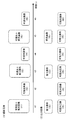
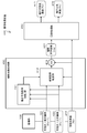
- FIG. 2 is a block diagram illustrating a configuration of an imaging apparatus that is an example of the image processing apparatus 100 of the present disclosure.
- the image processing apparatus of the present disclosure is not limited to the imaging apparatus, and includes, for example, an information processing apparatus such as a PC that inputs a captured image of the imaging apparatus and executes image processing.
- an information processing apparatus such as a PC that inputs a captured image of the imaging apparatus and executes image processing.
- a configuration and processing of an imaging apparatus will be described as an example of the image processing apparatus 100 of the present disclosure.
- Image processing other than the imaging processing described in the following embodiments is not limited to the imaging device, and can be executed by an information processing device such as a PC.
- An image processing apparatus 100 as an imaging apparatus illustrated in FIG. 2 includes a control unit 101, a storage unit 102, a codec 103, an input unit 104, an output unit 105, an imaging unit 106, and an image processing unit 120.
- the imaging unit 106 captures a visible fluorescence mixed image including both visible light imaging light and fluorescent imaging light that form a normal color image. Or the visible light image which is a normal color image, and a fluorescence image are image
- the fluorescent image is an image obtained by photographing the fluorescent component included in the reflected light from the substance in the living body.
- the control unit 101 controls various processes executed in the imaging apparatus 100, such as image capturing, signal processing for captured images, image recording processing, and display processing.
- the control unit 101 includes, for example, a CPU that executes processing according to various processing programs stored in the storage unit 102, and functions as a data processing unit that executes the program.
- the storage unit 102 includes a captured image storage unit, a processing program executed by the control unit 101, a storage unit for various parameters, and a RAM, a ROM, and the like that function as a work area for data processing.
- the codec 103 performs encoding and decoding processing such as compression and decompression processing of a captured image.
- the input unit 104 is a user operation unit, for example, and inputs control information such as shooting start and end, various mode settings, and the like.
- the output unit 105 includes a display unit, a speaker, and the like, and is used for displaying captured images and through images, outputting sound, and the like.
- the image processing unit 120 inputs a captured image from the imaging unit 106 and executes an image quality enhancement process for the input image. Specifically, for example, a corrected visible light image 151 and a corrected fluorescence image 152 with high image quality are generated.
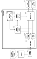
- the imaging unit 106 captures a visible fluorescence mixed image 210 including both visible light imaging light and fluorescent imaging light that form a normal color image.
- the visible fluorescence mixed image 210 captured by the imaging unit 106 is input to the image processing unit 120.
- the image processing unit 120 receives the visible fluorescence mixed image 210, generates and outputs a corrected visible light image 221 and a corrected fluorescence image 222 that have undergone image quality enhancement processing.
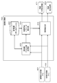
- the image processing unit 120 inputs the visible fluorescence mixed image 210 taken by the imaging unit 106 to the image separation unit 301, and the visible fluorescence mixed image 210 is a visible light component having a visible light component similar to a normal RGB color image.
- the optical image 211 is separated into a fluorescent image 212 made up of only fluorescent components. This is executed by, for example, matrix calculation using a separation matrix.
- the visible light image 211 and the fluorescence image 212 generated by the image separation process in the image separation unit 301 are input to the feature amount class classification processing unit 302 and the image correction unit 305.
- the feature amount class classification processing unit 302 receives the visible light image 211 and the fluorescence image 212, extracts the feature amount of the image from these images, executes class classification processing based on the extracted feature amount, and stores the storage unit ( And the classification result of the feature amount data is input to the image correction parameter calculation unit 304.
- the class classification process is a class classification process in so-called machine learning.
- it is a class classification for determining a correction mode and correction parameters as to what kind of image correction is effective for the image quality enhancement processing.
- the storage unit (database) 303 stores teacher data to be applied to this class classification, and the feature amount class classification processing unit 302 uses the teacher data stored in the storage unit (database) 303. Then, the optimum correction mode and the like for the high image quality processing for the input image (visible light image 211, fluorescent image 212) is determined.
- the correction mode determination information is input to the image correction parameter calculation unit 304.
- the image correction parameter calculation unit 304 uses the correction mode determination information input from the feature amount class classification processing unit 302 and the teacher data stored in the storage unit (database) 303 to display the visible light image 211 and the fluorescence image 212. An image correction parameter for performing the image quality enhancement process is determined. The determined image correction parameter is input to the image correction unit 305.
- the image correction unit 305 applies the image correction parameter input from the image correction parameter calculation unit 304 to execute the image correction processing of the visible light image 211 and the fluorescent image 212, and the corrected visible light subjected to the high image quality processing.
- An image 221 and a corrected fluorescence image 222 are generated and output.
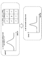
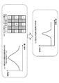
- FIG. 4 shows examples of the following three types of image feature amounts that can be extracted from at least one of the two images by the feature amount class classification processing unit 302.
- PSF Point Spread Function
- Luminance distribution information Noise information
- PSF point spread function
- This point spread function is an image feature quantity that can be acquired from only one of the visible light image 211 and the fluorescent image 212.
- “(2) Luminance distribution information” is distribution information of the luminance value of each pixel in the image.
- a graph luminance distribution graph
- the left side of the graph has a low luminance value
- the right side has a high luminance value.
- Such a luminance distribution is a luminance distribution corresponding to an edge region such as a boundary of a subject.
- Such luminance distribution information is an image feature amount that can be acquired from only one of the visible light image 211 and the fluorescent image 212.
- Noise information is information indicating noise included in an image.
- the image captured by the camera contains a certain amount of noise.
- a graph noise distribution graph in which the horizontal axis represents the pixel position and the vertical axis represents the pixel value is shown.
- the pixel value is a value obtained by adding a predetermined amount of noise to the original color and luminance of the subject.
- noise information is also an image feature quantity that can be acquired from only one of the visible light image 211 and the fluorescent image 212.
- These three image feature amounts shown in FIG. 4 are examples of feature amount data that the feature amount class classification processing unit 302 acquires from at least one of the visible light image 211 and the fluorescent image 212.
- the feature quantity class classification processing unit 302 acquires at least one of the three image feature quantities shown in FIG. 4 from at least one of the visible light image 211 and the fluorescent image 212.
- the image correction unit 325 executes image correction processing as image quality enhancement processing on the visible light image 211 and the fluorescent image 212 based on the acquired feature amount, and displays the corrected visible light image 221 and the corrected fluorescent image 222 with improved image quality. Generate and output.
- the imaging unit 106 captures a visible fluorescence mixed image 210 that includes both the imaging light in the visible light region and the imaging light in the fluorescent region that form a normal color image, and performs visible fluorescence mixing.
- an image 210 is input to the image processing unit 120.
- the image processing unit 120 generates two images of the visible light mixed image 210 and the visible light image 211 and the fluorescent image 212 in the image separation unit 301.
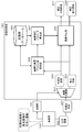
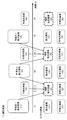
- FIG. 5 shows the configuration and processing of the image processing unit 120 when the imaging unit 106 captures a visible light image that is a normal color image and a fluorescent image alternately and inputs them to the image processing unit 120.
- the description will be given with reference.
- the imaging unit 106 illustrated in FIG. 5 captures a visible light image 231 corresponding to a normal color image and a fluorescent image 232 separately and inputs them to the image processing unit 120.
- the image processing unit 120 sequentially inputs a visible light image 231 and a fluorescent image 232, generates a corrected visible light image 241 obtained by performing image quality enhancement processing on each of these images, and a corrected fluorescent image 242 and outputs the corrected visible light image 242. To do.
- the visible light image 231 and the fluorescence image 232 that are sequentially captured by the imaging unit 106 are input to the image separation unit 321 of the image processing unit 120.
- the image separation unit 321 separates the input image from the imaging unit 106 into a visible light image 233 and a fluorescent image 234 by time division processing under the control of the control unit 101.
- the image input at timing t0 is a visible light image
- the input image at the next timing t1 is a fluorescent image
- t2 visible light image
- t3 fluorescent image
- the control unit 101 controls the image separation unit 321 according to the image capturing timing of the imaging unit 106 to perform a separation process between the visible light image 233 and the fluorescence image 234.
- the visible light image 233 and the fluorescence image 234 generated by the image separation process in the image separation unit 321 are input to the feature amount class classification processing unit 322 and the image correction unit 325.
- the feature amount class classification processing unit 322 receives the visible light image 233 and the fluorescence image 234, extracts the feature amount of the image from these images, executes the class classification process based on the extracted feature amount, and stores the storage unit ( And the classification result of the feature amount data is input to the image correction parameter calculation unit 324.
- the class classification process is a class classification process in so-called machine learning.
- it is a class classification for determining a correction mode that determines what kind of image correction is effective for the image quality enhancement processing.
- the storage unit (database) 323 stores teacher data to be applied to this class classification, and the feature amount class classification processing unit 322 uses the teacher data stored in the storage unit (database) 303.
- the optimum correction mode for the high image quality processing for the input image (visible light image 233, fluorescent image 234) is determined.
- the correction mode determination information is input to the image correction parameter calculation unit 324.
- the image correction parameter calculation unit 324 uses the correction mode determination information input from the feature amount class classification processing unit 322 and the teacher data stored in the storage unit (database) 323 to generate the visible light image 233 and the fluorescence image 234. An image correction parameter for performing the image quality enhancement process is determined. The determined image correction parameter is input to the image correction unit 325.
- the image correction unit 325 applies the image correction parameter input from the image correction parameter calculation unit 324 to execute the image correction processing of the visible light image 233 and the fluorescent image 234, and the corrected visible light subjected to the high image quality processing.
- An image 241 and a corrected fluorescence image 242 are generated and output.
- the feature amount data acquired from the visible light image 233 and the fluorescence image 234 by the feature amount class classification processing unit 322 is the data shown in FIG. 4 described above, and is, for example, the following data.
- PSF Point Spread Function
- Luminance distribution information (3) Noise information
- These three image feature amounts shown in FIG. 4 are examples of feature amount data that the feature amount class classification processing unit 322 acquires from at least one of the visible light image 233 and the fluorescent image 234.
- the image correction unit 325 executes image correction processing as image quality enhancement processing for the visible light image 233 and the fluorescent image 234 based on the acquired feature amount, and generates the corrected visible light image 241 and the corrected fluorescent image 242 with improved image quality. Generate and output.
- the image correction unit of the image processing unit shown in FIGS. 3 and 5 performs image correction processing for improving the image quality of the visible light image and the fluorescent image according to the correction mode and correction parameters determined based on these feature amounts. Execute. Hereinafter, a configuration for executing a high image quality process using blur mode information (PSF information) as an image feature amount will be described.
- PSF information blur mode information
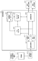
- FIG. 6 shows a configuration similar to that of the image processing unit 120 described above with reference to FIG. That is, the imaging unit 106 captures the visible fluorescent mixed image 210 including both the visible light imaging light and the fluorescent imaging light that form a normal color image.
- the visible fluorescence mixed image 210 captured by the imaging unit 106 is input to the image processing unit 120.
- the image processing unit 120 receives the visible fluorescence mixed image 210, generates and outputs a corrected visible light image 221 and a corrected fluorescence image 222 that have undergone image quality enhancement processing.
- the image processing unit 120 illustrated in FIG. 6 replaces the feature amount class classification processing unit 302 of the image processing unit 120 illustrated in FIG. 3 with a PSF estimation unit 330, and further replaces the image correction parameter calculation unit 304 with an inverse filter calculation unit 340. This corresponds to the configuration replaced with.
- the image processing unit 120 inputs the visible fluorescence mixed image 210 taken by the imaging unit 106 to the image separation unit 301, and the visible fluorescence mixed image 210 is a visible light component having a visible light component similar to a normal RGB color image.
- the optical image 211 is separated into a fluorescent image 212 made up of only fluorescent components. This is executed by, for example, matrix calculation using a separation matrix.
- the visible light image 211 and the fluorescence image 212 generated by the image separation process in the image separation unit 301 are input to the PSF estimation unit 330 and the image correction unit 305.
- the PSF estimation unit 330 receives the visible light image 211 and the fluorescence image 212, extracts a point spread function (PSF: Point Spread Function) as blur mode information as an image feature amount from these images, and extracts it.
- PSD Point Spread Function
- the class classification process based on the blur mode information (PSF information) is executed and stored in the storage unit (database), and the class classification result of the blur mode information (PSF information) is input to the inverse filter calculation unit 340.
- the class classification process is a class classification process in so-called machine learning. Here, based on the feature amount acquired from the image, it is a class classification for determining a correction mode that determines what kind of image correction is effective for the image quality enhancement processing.
- the storage unit (database) 303 stores teacher data to be applied to this classification, and the PSF estimation unit 330 uses the teacher data stored in the storage unit (database) 303 to A correction mode that is optimal for high image quality processing for the input image (visible light image 211, fluorescent image 212) is determined.
- the correction mode determination information is input to the inverse filter calculation unit 340.
- the inverse filter calculation unit 340 uses the correction mode determination information input from the PSF estimation unit 330 and the teacher data stored in the storage unit (database) 303 to improve the image quality of the visible light image 211 and the fluorescent image 212. For example, an inverse filter such as a Wiener filter applied to eliminate blur is generated. The generated inverse filter is input to the image correction unit 305.
- an inverse filter such as a Wiener filter applied to eliminate blur is generated.
- the generated inverse filter is input to the image correction unit 305.
- the image correction unit 305 applies the inverse filter input from the inverse filter calculation unit 340 to execute the image correction process of the visible light image 211 and the fluorescent image 212, and the corrected visible light image 221 subjected to the image quality enhancement process. Then, the corrected fluorescence image 222 is generated and output.
- PSF point spread function
- PSF point spread function
- An inverse filter generation process applied to an image correction process for improving image quality and a pixel value correction process using the inverse filter are executed.
- FIG. 7 illustrates processes executed by the PSF estimation unit 330, the inverse filter calculation unit 340, and the image correction unit 305, respectively.
- PSF point spread function
- the point spread function (PSF) is acquired using the fluorescence image 212.
- the point spread function (PSF) information extracted from the fluorescence image 212 by the PSF estimation unit 330 is input to the inverse filter calculation unit 340.
- the inverse filter calculation unit 340 is a filter for eliminating blur as a correction parameter applied to the correction process based on the point spread function (PSF) information extracted from the fluorescence image 212 by the PSF estimation unit 330 in step S12.
- a coefficient constituting the inverse filter is calculated. That is, a multiplication coefficient to be applied to the reference pixels around the correction target pixel is calculated.
- FIG. 8 shows the following figures.
- A1 Example of pixel value distribution of image before correction
- a2 Example of tap setting and correction parameter (multiplication coefficient K i )
- b Example of pixel value distribution of image after correction
- the pixel value distribution example of the image before correction is a pixel value distribution example of the fluorescence image that is the correction target image.
- the fluorescence image has a large amount of scattered light and a large amount of blur when, for example, a living body internal image is taken.
- the pixel value distribution is a distribution that smoothly reflects the subject luminance, resulting in a large blurred image.
- the inverse filter calculation unit 340 performs setting of a reference region (tap selection) for correcting such a fluorescent image with a large blur to obtain a clear image with a small blur, and further eliminates the blur.
- a coefficient constituting an inverse filter that is a filter, that is, a multiplication coefficient k i to be applied to reference pixels around the correction target pixel is calculated.
- a larger reference pixel region (tap region) is set as the amount of blur of the fluorescent image 212 is larger (multiplied), and multiplication as an effective correction parameter for eliminating the blur of the fluorescent image 212 is performed.
- the coefficient k i is determined.
- the “(a2) tap setting and an example of the correction parameter (multiplication coefficient K i )” in FIG. 8 refers to the surrounding reference used for correcting the pixel value of the correction target pixel with the pixel to be corrected as the center. It represents the value of the multiplication coefficient k i for the position and the reference pixels of the pixel.
- 3 ⁇ 3 9 pixels centered on the correction target pixel are shown.
- 0, ⁇ 1, and 9 shown in the nine pixel positions are multiplication coefficients k i that are correction parameters calculated by the inverse filter calculation unit 340.
- i is a pixel position identifier indicating a pixel position.
- a pixel position to be referred to in order to calculate the correction pixel value of the correction target pixel is selected as the tap position.
- a pixel position set to ⁇ 1 or 9 is a tap.
- the inverse filter calculation unit 340 calculates a multiplication factor k i for multiplying the pixel values of the tap position. It is ⁇ 1 and 9 shown in FIG.
- the filter calculated by the inverse filter calculation unit 340 is a filter for eliminating blur, and specifically, for example, a Wiener filter or the like is generated.
- the inverse filter generated by the inverse filter calculation unit 340 is input to the image correction unit 305.
- the image correction unit 305 calculates the correction pixel value of the fluorescent image 212 using the inverse filter generated by the inverse filter calculation unit 340. Specifically, the correction pixel value y of the correction target pixel is calculated by applying the following correction pixel value calculation formula (Formula 1) shown in Step S13 of FIG. The corrected pixel value y is calculated according to the following (Equation 1).
- each symbol has the following meaning.
- y correction pixel value of correction target pixel x i : pixel value of reference pixel i: pixel identifier of reference pixel k i : multiplication coefficient corresponding to reference pixel i
- i is an identifier of a pixel.
- k i is a multiplication coefficient for the pixel value x i set at each pixel position i.
- the pixel value of the correction target pixel is calculated according to the above (Equation 1).
- tap setting and the setting of the correction parameter (multiplication coefficient) shown in FIG. 8A2 are examples, and the tap and the correction parameter are changed to various settings according to the feature amount.
- the image correcting unit 305 sequentially calculates the corrected pixel values of all the constituent pixels of the fluorescent image 212 according to the above (Equation 1), and generates and outputs the calculated corrected fluorescent image 222.
- the pixel value distribution of the corrected fluorescence image 222 is an image in which the gradient of the pixel value change is steeper and the blur is eliminated compared to the pixel value distribution of the fluorescence image before correction shown in FIG.
- FIGS. 8A1 and 8A2 are setting examples of tap setting and correction parameters (multiplication coefficient k i ) when the blur spread is relatively small.
- the tap setting and the setting of the correction parameter (multiplication coefficient k i ) are changed according to the PSF acquired as the feature amount, that is, the blur mode.
- FIG. 9 shows an example of setting tap settings and correction parameters (multiplication coefficient K i ) when the blur spread is relatively large.
- the pixel area to be used as the reference determination is set to be larger, and the correction pixel is based on the pixel values of a wider range of reference pixels. Processing to determine the value is performed.
- a reference pixel region selection process to be applied to the correction process that is, a tap selection process is executed.
- correction parameters multiplication coefficients
- FIG. 10 illustrates the configuration and processing of the image processing unit 120 when the imaging unit 106 captures a visible light image, which is a normal color image, and a fluorescent image alternately and inputs them to the image processing unit 120.
- the configuration of the image processing apparatus shown in FIG. 10 is the same as that of the image processing apparatus with reference to FIG.
- the imaging unit 106 illustrated in FIG. 10 captures a visible light image 231 corresponding to a normal color image and a fluorescent image 232 separately and inputs them to the image processing unit 120.
- the image processing unit 120 sequentially inputs a visible light image 231 and a fluorescent image 232, generates a corrected visible light image 241 obtained by performing image quality enhancement processing on each of these images, and a corrected fluorescent image 242 and outputs the corrected visible light image 242. To do.
- the image processing unit 120 illustrated in FIG. 10 replaces the feature amount class classification processing unit 322 of the image processing unit 120 illustrated in FIG. 5 with the PSF estimation unit 350, and further replaces the image correction parameter calculation unit 324 with the inverse filter calculation unit 360. This corresponds to the configuration replaced with.
- the visible light image 231 and the fluorescence image 232 that are sequentially captured by the imaging unit 106 are input to the image separation unit 321 of the image processing unit 120.
- the image separation unit 321 separates the input image from the imaging unit 106 into a visible light image 233 and a fluorescent image 234 by time division processing under the control of the control unit 101.
- the image input at timing t0 is a visible light image
- the input image at the next timing t1 is a fluorescent image
- t2 visible light image
- t3 fluorescent image
- the control unit 101 controls the image separation unit 321 according to the image capturing timing of the imaging unit 106 to perform a separation process between the visible light image 233 and the fluorescence image 234.
- the visible light image 233 and the fluorescence image 234 generated by the image separation process in the image separation unit 301 are input to the PSF estimation unit 350 and the image correction unit 325.
- the PSF estimation unit 350 receives the visible light image 233 and the fluorescence image 234, and extracts and extracts a point spread function (PSF: Point Spread Function) as blur feature information as an image feature amount from these images.
- PSF Point Spread Function
- a class classification process based on the blur mode information (PSF information) is executed and stored in the storage unit (database), and the class classification result of the blur mode information (PSF information) is input to the inverse filter calculation unit 360.
- the class classification process is a class classification process in so-called machine learning. Here, based on the feature amount acquired from the image, it is a class classification for determining a correction mode that determines what kind of image correction is effective for the image quality enhancement processing.
- the storage unit (database) 323 stores teacher data to be applied to this class classification, and the PSF estimation unit 350 uses the teacher data stored in the storage unit (database) 323, A correction mode that is optimal for high image quality processing for the input image (visible light image 233, fluorescent image 234) is determined.
- the correction mode determination information is input to the inverse filter calculation unit 360.
- the inverse filter calculation unit 360 uses the correction mode determination information input from the PSF estimation unit 350 and the teacher data stored in the storage unit (database) 323 to improve the image quality of the visible light image 233 and the fluorescence image 234. For example, an inverse filter such as a Wiener filter applied to eliminate blur is generated. The generated inverse filter is input to the image correction unit 325.
- an inverse filter such as a Wiener filter applied to eliminate blur is generated.
- the generated inverse filter is input to the image correction unit 325.
- the image correcting unit 325 applies the inverse filter input from the inverse filter calculating unit 360 to execute the image correction processing of the visible light image 233 and the fluorescent image 234, and the corrected visible light image 241 subjected to the image quality enhancement processing. Then, the corrected fluorescence image 242 is generated and output.
- FIG. 10 shows processes executed by the PSF estimation unit 350, the inverse filter calculation unit 360, and the image correction unit 325 as steps S21 to S23.
- PSF point spread function
- a point spread function (PSF) is acquired using the fluorescence image 234.
- the point spread function (PSF) information extracted from the fluorescence image 234 by the PSF estimation unit 350 is input to the inverse filter calculation unit 360.
- the inverse filter calculation unit 360 is a filter for eliminating blur as a correction parameter to be applied to the correction processing based on the point spread function (PSF) information extracted from the fluorescence image 234 by the PSF estimation unit 350 in step S22.
- a coefficient constituting the inverse filter is calculated. That is, a multiplication coefficient to be applied to the reference pixels around the correction target pixel is calculated.
- the correction parameter calculation process in the inverse filter calculation unit 360 is the same process as described above with reference to FIGS.
- the filter calculated by the inverse filter calculation unit 360 is a filter for eliminating blur, and specifically generates, for example, a Wiener filter.
- the inverse filter generated by the inverse filter calculation unit 360 is input to the image correction unit 325.
- the image correction unit 325 calculates the correction pixel value of the fluorescence image 234 using the inverse filter generated by the inverse filter calculation unit 360. Specifically, the correction pixel value y of the correction target pixel is calculated by applying the following correction pixel value calculation formula (formula 2) shown in step S23 of FIG. The corrected pixel value y is calculated according to the following (Equation 2).
- each symbol has the following meaning.
- y correction pixel value of correction target pixel x i : pixel value of reference pixel i: pixel identifier of reference pixel k i : multiplication coefficient corresponding to reference pixel i
- i is an identifier of a pixel.
- k i is a multiplication coefficient for the pixel value x i set at each pixel position i.
- the pixel value of the correction target pixel is calculated according to the above (Equation 2).
- a reference pixel region selection process to be applied to the correction process that is, a tap selection process is executed.
- correction parameters multiplication coefficients
- the imaging unit 106 of the image processing apparatus 100 illustrated in FIG. 2 captures different types of images such as a visible light image, a fluorescent image, or a visible light + fluorescent image.
- the frame rate of the visible light image that can be output and the frame rate of the fluorescent image do not always match.
- the imaging unit 106 alternately captures the following two different images.
- (b) Visible light + fluorescence image Specifically, it is the setting of the captured image shown in FIG.
- the time-series sequence of the captured image shown in FIG. 11 (1) is as follows. At time t1, a visible light + fluorescence image (f1) is taken. At time t2, a visible light image (f2) is taken. At time t3, a visible light + fluorescence image (f3) is taken. At time t4, a visible light image (f4) is taken. At time t5, a visible light + fluorescence image (f5) is taken. At time t6, a visible light image (f6) is taken. Hereinafter, this is repeated.
- the image that can be output is the setting of the output image in FIG. That is, the following settings are made.
- a visible light image (f1) and a fluorescent image (f1) are obtained by an image separation process of visible light + fluorescence image (f1).
- the fluorescence image is not output and only the visible light image (f2) is output.
- a visible light image (f3) and a fluorescent image (f3) are obtained by the image separation process of visible light + fluorescence image (f3).
- the fluorescence image is not output and only the visible light image (f4) is output.
- a visible light image (f5) and a fluorescent image (f5) are obtained by the image separation process of visible light + fluorescence image (f5).
- the fluorescence image is not output and only the visible light image (f6) is output. Hereinafter, this is repeated.
- the output fluorescent image has a frame rate that is half the frame rate of the visible light image.
- FIG. 12 is a diagram for explaining image interpolation processing executed by the image processing apparatus according to the present embodiment.
- FIG. 12 (1) shows the setting of the captured image similar to FIG. 11 (1), and the time-series sequence of the captured image is as follows.
- a visible light + fluorescence image (f1) is taken.
- a visible light image (f2) is taken.
- a visible light + fluorescence image (f3) is taken.
- a visible light image (f4) is taken.
- a visible light + fluorescence image (f5) is taken.
- a visible light image (f6) is taken.
- this is repeated.
- the interpolated fluorescence images are generated at timings t2, t4, t6,. They are the interpolation fluorescence image (t2), the interpolation fluorescence image (t4), and the interpolation fluorescence image (t6) shown in FIG.
- an output image shown in FIG. 12B is obtained. That is, the following settings are made.
- a visible light image (f1) and a fluorescent image (f1) are obtained by an image separation process of visible light + fluorescence image (f1).
- a visible light image (f2) and an interpolated fluorescent image (f2) are output.
- a visible light image (f3) and a fluorescent image (f3) are obtained by the image separation process of visible light + fluorescence image (f3).
- a visible light image (f4) and an interpolated fluorescent image (f4) are output.
- a visible light image (f5) and a fluorescent image (f5) are obtained by the image separation process of visible light + fluorescence image (f5).
- a visible light image (f6) and an interpolated fluorescence image (f6) are output. Hereinafter, this is repeated.
- the output fluorescent image can have the same frame rate as the frame rate of the visible light image.
- a configuration example and processing of an image processing apparatus that includes an image processing unit that performs image interpolation processing and performs image quality enhancement processing will be described with reference to FIG.
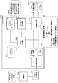
- the imaging unit 106 of the image processing apparatus 400 illustrated in FIG. 13 captures an image using the captured image capturing sequence described with reference to FIG. FIG. 13 shows the following three time-series captured image frames.
- (A) Captured image frame at time t (n ⁇ 1) visible light + fluorescence image (Fn ⁇ 1) 421
- (B) Captured image frame at time t (n) visible light image (Fn) 422,
- (C) Captured image frame at time t (n + 1) visible light + fluorescence image (Fn + 1) 423,
- the interpolation image generation unit 410 includes a motion prediction processing (ME) unit 411, an interpolation image estimation unit 412, and a subtraction unit 413.
- ME motion prediction processing
- the motion prediction processing (ME) unit 411 inputs three image frames 421 to 423, performs motion prediction (ME) between these image frames, and inputs motion information to the interpolated image estimation unit 412. .
- the three image frames 421 to 423 are images that were previously captured in accordance with the photographing sequence of FIG. 12 (1) photographing pixels, and are photographed at different photographing timings. Therefore, the position of the subject included in each image is shifted due to the movement or blurring of the subject.
- the motion prediction processing (ME) unit 411 calculates a subject position shift amount between the three image frames 421 to 423 and inputs this to the interpolated image estimation unit 412 as motion information.
- the interpolated image estimation unit 412 inputs the three image frames 421 to 423, and inputs the motion information of these three images from the motion prediction processing (ME) unit 411.
- the interpolated image estimation unit 412 performs the alignment of the three image frames 421 to 423 by applying the motion information of the three images input from the motion prediction processing (ME) unit 411. That is, alignment processing is performed to eliminate the shift so that the same subject is positioned at the same coordinate position of each image.
- the interpolated image estimation unit 412 further blends the three image frames 421 to 423 after alignment to generate a visible light + fluorescence image (Fn) that is a virtual captured image frame at time t (n). .
- the visible light + fluorescence image (Fn) generated by the interpolation image estimation unit 412 is input to the subtraction unit 413.
- the subtraction unit 413 performs processing for subtracting the visible light image (Fn) 422 from the visible light + fluorescence image (Fn) generated by the interpolation image estimation unit 412.
- an interpolated fluorescence image (Fn) 431 is generated.
- the interpolated fluorescent image (Fn) 431 is a virtual image corresponding to the fluorescent image captured at the imaging timing at time t (n) when the fluorescent image is not actually captured.
- An interpolated fluorescence image (Fn) 431 that is an estimated image at the imaging timing at time t (n) and a visible light image (Fn) 422 actually captured at the imaging timing at time t (n) are input to the image processing unit 450. Entered.
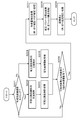
- the configuration and processing of the image processing unit 450 will be described with reference to FIG.
- the configuration of the image processing unit 450 illustrated in FIG. 14 corresponds to a configuration in which the image separation unit is omitted from the image processing unit 120 described with reference to FIGS.
- the visible light image 422 input from the imaging unit 106 and the interpolated fluorescent image 431 generated by the interpolated image generating unit 410 are input to the feature amount class classification processing unit 451 and the image correcting unit 454 of the image processing unit 450.
- the feature amount class classification processing unit 451 receives the visible light image 422 and the interpolated fluorescent image 431, extracts the feature amount of the image from these images, executes the class classification process based on the extracted feature amount, and the storage unit
- the data is stored in the (database) and the classification result of the feature data is input to the image correction parameter calculation unit 453.
- the class classification process is a class classification process in so-called machine learning.
- it is a class classification for determining a correction mode that determines what kind of image correction is effective for the image quality enhancement processing.
- the storage unit (database) 452 stores teacher data to be applied to this class classification, and the feature amount class classification processing unit 451 uses the teacher data stored in the storage unit (database) 303. Then, the optimum correction mode for the image quality enhancement processing for the input image (visible light image 422 and interpolated fluorescent image 431) is determined.
- the correction mode determination information is input to the image correction parameter calculation unit 453.
- the image correction parameter calculation unit 453 uses the correction mode determination information input from the feature amount class classification processing unit 451 and the teacher data stored in the storage unit (database) 452 to use the visible light image 422 and the interpolated fluorescent image. An image correction parameter for performing the image quality improvement process 431 is determined. The determined image correction parameter is input to the image correction unit 454.
- the image correction unit 454 applies the image correction parameter input from the image correction parameter calculation unit 453, executes the image correction processing of the visible light image 422 and the interpolated fluorescent image 431, and performs the correction for which the image quality improvement processing has been performed.
- a visible light image 471 and a corrected fluorescence image 472 are generated and output.
- the feature amount data acquired from the visible light image 422 and the interpolated fluorescence image 431 by the feature amount class classification processing unit 451 is the data illustrated in FIG. 4 described above, and is, for example, the following data.
- PSF Point Spread Function
- Luminance distribution information (3) Noise information
- These three image feature amounts shown in FIG. 4 are examples of feature amount data that the feature amount class classification processing unit 451 acquires from at least one of the visible light image 422 and the interpolated fluorescence image 431.
- the image correction unit 454 performs image correction processing as image quality enhancement processing on the visible light image 422 and the interpolated fluorescent image 431 based on the acquired feature amount, and corrects the visible light image 471 and the corrected fluorescent image with improved image quality. 472 is generated and output.
- a shooting sequence as shown in FIG. The sequence of captured images shown in FIG. It is an image capturing sequence for alternately capturing a plurality of visible light image frames and a plurality of fluorescent image frames.
- the high image quality processing for the fluorescent image (f4) is performed by applying the configuration of the image processing unit described above with reference to FIG. It can be executed by applying the optical image (f3).
- the optical image (f3) for the three image frames of the fluorescent image (f5) to the fluorescent image (f7), there is no visible light image that is captured immediately before the capturing timing of these three image frames. Therefore, it becomes impossible to perform the image quality enhancement process using the two consecutively photographed image frames described with reference to FIG.
- an image correction process as shown in FIG. 15 is executed. Specifically, the image correction mode determined by the image feature amount class classification processing unit 501 based on the visible light image (f3) and the fluorescence image (f4) and the correction parameter determined by the image correction parameter calculation unit 502 are applied. In addition, not only the fluorescent image (f4) but also image corrections of the fluorescent images (f5) to (f7) that are continuously photographed thereafter are executed.
- corrected fluorescent images (f4) to corrected fluorescent images (f7) can be generated and output as output images. That is, even when a visible light image and a fluorescent image are not alternately captured, it is possible to generate and output a corrected fluorescent image with high image quality.
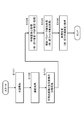
- FIG. 16 is a flowchart illustrating a basic processing sequence executed in the image processing apparatus.
- the processing according to the flow shown in FIG. 16 is executed under the control of a control unit having a program execution function, for example, according to a program stored in the storage unit of the image processing apparatus.
- a control unit having a program execution function for example, according to a program stored in the storage unit of the image processing apparatus.
- Steps S101 to S102 are image photographing processing.
- the photographed image is executed as a photographing process of a visible light image and a fluorescent image or a visible fluorescent mixed image.
- the light source irradiation in step S101 includes a visible light irradiation process for capturing a visible light image and an excitation light irradiation process for capturing a fluorescent image.
- the photographing process in step S102 is an image photographing process under irradiation of these light sources, and is a photographing process of a visible light image and a fluorescent image or a visible fluorescent mixed image.
- Step S103 The processing in steps S103 to S106 is image processing in the image processing unit shown in, for example, FIGS.
- step S103 a visible light image and a fluorescence image are separated.
- This processing is executed by, for example, the image separation unit 301 in FIG. 3 or the image separation unit 321 shown in FIG.
- the visible fluorescence mixed image 210 photographed by the imaging unit 106 is input to the image separation unit 301, and the visible fluorescence mixed image 210 is made of visible light composed of visible light components similar to a normal RGB color image.
- the image is separated into an image 211 and a fluorescence image 212 composed only of the fluorescence component. This is executed by, for example, matrix calculation using a separation matrix.
- the visible light image 231 and the fluorescence image 232 that are sequentially captured by the imaging unit 106 are input to the image separation unit 321 of the image processing unit 120.
- the image separation unit 321 separates the input image from the imaging unit 106 into a visible light image 233 and a fluorescent image 234 by time division processing under the control of the control unit 101.
- Step S104 feature amount extraction from the image is performed in step S104.
- This process is, for example, a process executed by the feature amount class classification processing unit shown in FIGS.
- the feature amount classification processing unit inputs a visible light image and a fluorescence image, extracts the feature amount of the image from these images, executes a class classification process based on the extracted feature amount, and stores it in a storage unit (database). In addition to storing, the classification result of the feature data is input to the image correction parameter calculation unit.
- Other feature amounts include, for example, luminance distribution information and noise information as described above with reference to FIG.
- step S105 correction parameter calculation processing is executed.
- This process is, for example, a process executed by the image correction parameter calculation unit shown in FIGS.
- the image correction parameter calculation unit performs high-quality processing of a visible light image and a fluorescent image using correction mode determination information input from the feature class classification processing unit and teacher data stored in a storage unit (database). An image correction parameter to be performed is determined. The determined image correction parameter is input to the image correction unit.
- the correction parameter calculated by the image correction parameter calculation unit is a multiplication coefficient that is a setting parameter of an inverse filter for eliminating blur.
- the image correction parameter calculation unit generates an inverse filter that is applied to blur elimination such as a Wiener filter.
- Step S106 an image correction process is executed.
- This process is, for example, a process executed by the image correction unit shown in FIGS.
- the image correction unit applies the image correction parameter input from the image correction parameter calculation unit and executes image correction processing of a visible light image or a fluorescent image to perform a corrected visible light image subjected to high image quality processing or correction Generate and output a fluorescence image.
- a specific example of the correction process is a pixel value correction process to which an inverse filter that executes a blur elimination process such as a Wiener filter is applied.
- a blur elimination process such as a Wiener filter
- the blur elimination process described above with reference to FIGS. 6 to 10 is executed.
- this image correction process a corrected image with high image quality that is free from blurring is output.
- the processing according to the flow shown in FIG. 17 is executed under the control of a control unit having a program execution function, for example, according to a program stored in the storage unit of the image processing apparatus.
- a control unit having a program execution function for example, according to a program stored in the storage unit of the image processing apparatus.
- Step S201 the control unit determines whether it is a visible light image capturing timing or a fluorescent image capturing timing. If it is determined that it is the timing for capturing a visible light image, the process proceeds to step S202. On the other hand, if it is determined that the fluorescent image capturing timing is reached, the process proceeds to step S204.
- Steps S202 to S203 If the control unit determines in step S201 that it is the timing for capturing a visible light image, in steps S202 to S203, the imaging unit performs light irradiation processing and visible light necessary for visible light image capturing under the control of the control unit. Optical image shooting processing is performed.
- Steps S204 to S205 On the other hand, if it is determined in step S201 that the control unit is the timing for capturing a fluorescent image, in steps S204 to S205, the imaging unit performs light irradiation processing and fluorescence necessary for fluorescent image capturing under the control of the control unit. An image photographing process is performed.
- step S ⁇ b> 206 the control unit determines whether shooting of one image pair of a visible light image and a fluorescent image has been completed. When photographing of one image pair of the visible light image and the fluorescence image is not completed, the process returns to step S201, and the processes in and after step S201 are repeated. On the other hand, if it is determined that shooting of one image pair of a visible light image and a fluorescence image has been completed, the process proceeds to step S207.
- Step S207 The processing in steps S207 to S209 is image processing executed by the image processing unit shown in FIGS.
- step S207 feature amounts are extracted from the image.
- This process is, for example, a process executed by the feature amount class classification processing unit shown in FIG.
- the feature amount classification processing unit inputs a visible light image and a fluorescence image, extracts the feature amount of the image from these images, executes a class classification process based on the extracted feature amount, and stores it in a storage unit (database). In addition to storing, the classification result of the feature data is input to the image correction parameter calculation unit.
- Other feature amounts include, for example, luminance distribution information and noise information as described above with reference to FIG.
- step S208 correction parameter calculation processing is executed.
- This process is, for example, a process executed by the image correction parameter calculation unit shown in FIG.
- the image correction parameter calculation unit performs high-quality processing of a visible light image and a fluorescent image using correction mode determination information input from the feature class classification processing unit and teacher data stored in a storage unit (database). An image correction parameter to be performed is determined. The determined image correction parameter is input to the image correction unit.
- the correction parameter calculated by the image correction parameter calculation unit is a multiplication coefficient that is a setting parameter of an inverse filter for eliminating blur.
- the image correction parameter calculation unit generates an inverse filter that is applied to blur elimination such as a Wiener filter.
- step S209 image correction processing is executed.
- This process is, for example, a process executed by the image correction unit shown in FIG.
- the image correction unit applies the image correction parameter input from the image correction parameter calculation unit and executes image correction processing of a visible light image or a fluorescent image to perform a corrected visible light image subjected to high image quality processing or correction Generate and output a fluorescence image.
- a specific example of the correction process is a pixel value correction process to which an inverse filter that executes a blur elimination process such as a Wiener filter is applied.
- a blur elimination process such as a Wiener filter
- the blur elimination process described above with reference to FIGS. 6 to 10 is executed.
- this image correction process a corrected image with high image quality that is free from blurring is output.
- the flow shown in FIG. 18 includes a visible light image capturing mode that performs continuous capturing of a visible light image and a fluorescent image capturing that performs continuous capturing of a fluorescent image as shown in FIG. 15 (1) image sequence of captured images. It is a flow explaining a process in case it is the setting which can switch a mode alternately.
- the processing according to the flow shown in FIG. 18 is executed under the control of a control unit having a program execution function, for example, according to a program stored in the storage unit of the image processing apparatus.
- a control unit having a program execution function for example, according to a program stored in the storage unit of the image processing apparatus.
- Step S301 First, in step S301, the control unit determines whether the current photographing mode is a visible light image photographing mode for continuously photographing a visible light image or a fluorescent image photographing mode for continuously photographing a fluorescent image.
- step S302 If it is determined that the visible light image capturing mode is set, the process proceeds to step S302. On the other hand, if it is determined that the fluorescent image photographing mode is set, the process proceeds to step S304.
- Steps S302 to S303 When it is determined in step S301 that the control unit is in the visible light image capturing mode, in steps S302 to S303, the imaging unit performs light irradiation processing and visible light necessary for visible light image capturing under the control of the control unit. An image photographing process is performed.
- Steps S304 to S305 On the other hand, when it is determined in step S301 that the control unit is in the fluorescence image capturing mode, in steps S304 to S305, the imaging unit performs light irradiation processing and fluorescence image necessary for fluorescence image capturing under the control of the control unit. Perform shooting processing.
- Step S306 the control unit determines whether or not a continuous captured image pair of a visible light image and a fluorescent image has been acquired.
- the timing when it is determined that the continuous captured image pair of the visible light image and the fluorescence image is acquired is, for example, the acquisition timing of the fluorescence image (f4) shown in FIG.
- step S301 When it is not the acquisition timing of one set of continuously shot image pairs of a visible light image and a fluorescent image, the process returns to step S301, and the processes after step S301 are repeated. On the other hand, if it is determined that one continuous captured image pair of a visible light image and a fluorescent image has been acquired, the process proceeds to step S307.
- Step S307 The processing in steps S307 to S309 is image processing executed in the image processing unit shown in FIG. 2, FIG. 3, FIG.
- step S307 feature amounts are extracted from the image.
- This process is, for example, a process executed by the feature amount class classification processing unit shown in FIGS.
- the feature amount classification processing unit inputs a visible light image and a fluorescence image, extracts the feature amount of the image from these images, executes a class classification process based on the extracted feature amount, and stores it in a storage unit (database). In addition to storing, the classification result of the feature data is input to the image correction parameter calculation unit.
- Other feature amounts include, for example, luminance distribution information and noise information as described above with reference to FIG.
- step S308 correction parameter calculation processing is executed.
- This process is a process executed by the image correction parameter calculation unit shown in FIGS. 3 and 5, for example.
- the image correction parameter calculation unit performs high-quality processing of a visible light image and a fluorescent image using correction mode determination information input from the feature class classification processing unit and teacher data stored in a storage unit (database). An image correction parameter to be performed is determined. The determined image correction parameter is input to the image correction unit.
- the correction parameter calculated by the image correction parameter calculation unit is a multiplication coefficient that is a setting parameter of an inverse filter for eliminating blur.
- the image correction parameter calculation unit generates an inverse filter that is applied to blur elimination such as a Wiener filter.
- step S309 image correction processing is executed.
- This process is a process executed by the image correction unit shown in FIGS.
- the image correction unit applies the image correction parameter input from the image correction parameter calculation unit and executes image correction processing of a visible light image or a fluorescent image to perform a corrected visible light image subjected to high image quality processing or correction Generate and output a fluorescence image.
- a specific example of the correction process is a pixel value correction process to which an inverse filter that executes a blur elimination process such as a Wiener filter is applied.
- a blur elimination process such as a Wiener filter
- the blur elimination process described above with reference to FIGS. 6 to 10 is executed.
- this image correction process a corrected image with high image quality that is free from blurring is output.
- Step S310 Next, in step S310, it is determined whether switching of the image capturing mode has occurred.
- step S309 image correction is performed on the image.
- This image correction is performed using the correction mode and the correction parameter determined based on the continuous captured image pair of the visible light image and the fluorescent image acquired in step S306.
- This process corresponds to, for example, an image correction process for the fluorescence image (f5) to the fluorescence image (f7) shown in FIG.
- the image correction for the fluorescence image (f5) to the fluorescence image (f7) shown in FIG. 15 is executed using the correction mode and the correction parameter determined based on the visible light image (f3) and the fluorescence image (f4). .
- step S310 If it is determined in step S310 that the switching of the image capturing mode has occurred, the process returns to step S301, and the processing from step S301 is executed.
- the processing according to this flow makes it possible to perform image correction on all images even when the image capturing sequence as shown in FIG. 15 described above is executed.
- FIG. 19 is a diagram illustrating a hardware configuration example of an image processing apparatus that executes the processing of the present disclosure.
- a CPU (Central Processing Unit) 601 functions as a control unit or a data processing unit that executes various processes in accordance with a program stored in a ROM (Read Only Memory) 602 or a storage unit 608. For example, processing according to the sequence described in the above-described embodiment is executed.
- a RAM (Random Access Memory) 603 stores programs executed by the CPU 601 and data. These CPU 601, ROM 602, and RAM 603 are connected to each other by a bus 604.
- the CPU 601 is connected to an input / output interface 605 via a bus 604.
- the input / output interface 605 inputs an image captured by the image capturing unit 621 and includes various switches that can be input by a user, a keyboard, a mouse, a microphone, and the like.
- An output unit 607 that outputs data to the unit 606, the display unit 622, a speaker, and the like is connected.
- the CPU 601 executes various processes in response to commands input from the input unit 606 and outputs the processing results to the output unit 607, for example.
- the storage unit 608 connected to the input / output interface 605 includes, for example, a hard disk and stores programs executed by the CPU 601 and various data.
- a communication unit 609 functions as a transmission / reception unit for Wi-Fi communication, Bluetooth (registered trademark) communication, and other data communication via a network such as the Internet or a local area network, and communicates with an external device.
- the drive 610 connected to the input / output interface 605 drives a removable medium 611 such as a magnetic disk, an optical disk, a magneto-optical disk, or a semiconductor memory such as a memory card, and executes data recording or reading.
- a removable medium 611 such as a magnetic disk, an optical disk, a magneto-optical disk, or a semiconductor memory such as a memory card
- a feature class classification processing unit that inputs a fluorescence image and a visible light image and extracts a feature from at least one of the images;
- An image processing apparatus having an image correction unit that performs a pixel value correction process on the fluorescent image based on a correction parameter determined according to the feature amount.
- the image processing apparatus further includes: A correction parameter calculation unit that determines a correction parameter used for pixel value correction in the image correction unit based on the feature amount;
- the image correction unit The image processing apparatus according to (1), wherein a pixel value correction process using the correction parameter determined by the correction parameter calculation unit is executed.
- the feature class classification processing unit Obtain blur mode information from the fluorescent image,
- the image correction unit The image processing apparatus according to (1) or (2), wherein pixel value correction processing of the fluorescent image is executed so as to reduce blur of the fluorescent image.
- the image processing apparatus further includes: A correction parameter calculation unit that determines a correction parameter used for pixel value correction in the image correction unit based on the feature amount; The correction parameter calculation unit determines a correction parameter for eliminating the blur of the fluorescent image, The image correction unit The image processing apparatus according to (3), wherein a pixel value correction process using the correction parameter determined by the correction parameter calculation unit is executed.
- the feature quantity class classification processing unit From at least one of the fluorescent image or the visible light image, (A) Luminance distribution information (b) Blur mode information (c) Noise information The image processing apparatus according to any one of (1) to (4), wherein the feature amount of any of (a) to (c) is extracted.
- the image processing apparatus includes: An image separation unit that inputs a mixed image of a visible light image and a fluorescent image and generates a visible light image and a fluorescent image from the mixed image;
- the feature quantity classification processing unit Input the fluorescence image and visible light image generated by the image separation unit,
- the image correction unit The image processing apparatus according to any one of (1) to (5), wherein a pixel value correction process based on a correction parameter determined according to the feature amount is executed on the fluorescence image generated by the image separation unit.
- the image processing apparatus includes: It has an image separation unit that alternately inputs a visible light image and a fluorescent image, and separates and outputs the input image into a visible light image and a fluorescent image,
- the feature quantity classification processing unit Input a fluorescent image and a visible light image output from the image separation unit,
- the image correction unit The image processing apparatus according to any one of (1) to (6), wherein a pixel value correction process based on a correction parameter determined according to the feature amount is executed on the fluorescent image output from the image separation unit.
- the image correction unit When a fluorescent image is continuous as an input image, Applying correction parameters determined based on feature values obtained by applying a pair of continuous captured images of visible light and fluorescent images in the past that are closest in time, and executing correction processing of continuous input fluorescent images (1)
- the image processing device according to any one of (7).
- the image processing apparatus includes: Furthermore, it has an interpolated image generation unit that generates a virtual fluorescent image at the non-photographing timing of the fluorescent image based on the previous and next captured images,
- the feature quantity classification processing unit Input the interpolated image generated by the interpolated image generation unit to execute a feature amount extraction process,
- the image correction unit The image processing device according to any one of (1) to (8), wherein a pixel value correction process based on a correction parameter determined according to the feature amount is executed on the interpolation image generated by the interpolation image generation unit.
- the image correction unit The image processing apparatus according to any one of (1) to (9), wherein a pixel value correction process is executed on the visible light image based on a correction parameter determined according to the feature amount.
- An imaging unit that performs imaging processing of a visible light image and a fluorescence image or a visible fluorescence mixed image;
- An image separation unit that inputs a captured image of the imaging unit and separates and outputs a visible light image and a fluorescence image from the input image;
- a feature amount classification processing unit that inputs a fluorescent image and a visible light image output from the image separation unit and extracts a feature amount from at least one of the images;
- An imaging apparatus having an image correction unit that executes a pixel value correction process on a fluorescence image output from the image separation unit based on a correction parameter determined according to the feature amount.
- the imaging apparatus further includes: A correction parameter calculation unit that determines a correction parameter used for pixel value correction in the image correction unit based on the feature amount;
- the image correction unit The imaging apparatus according to (11), wherein a pixel value correction process using the correction parameter determined by the correction parameter calculation unit is executed.
- the feature amount class classification processing unit includes: Obtain blur mode information from the fluorescent image, The image correction unit The imaging apparatus according to claim 11, wherein pixel value correction processing of the fluorescent image is executed so as to reduce blur of the fluorescent image.
- the imaging device may further include: A correction parameter calculation unit that determines a correction parameter used for pixel value correction in the image correction unit based on the feature amount; The correction parameter calculation unit determines a correction parameter for eliminating the blur of the fluorescent image, The image correction unit The imaging apparatus according to (13), wherein a pixel value correction process using the correction parameter determined by the correction parameter calculation unit is executed.
- An image processing method executed in the image processing apparatus A feature quantity classification processing unit that inputs a fluorescent image and a visible light image and extracts a feature quantity from at least one of the images; and An image processing method in which an image correction unit executes an image correction step of executing a pixel value correction process on the fluorescent image based on a correction parameter determined according to the feature amount.
- a program for executing image processing in an image processing apparatus In the feature quantity classification processing unit, a fluorescent image and a visible light image are input, and feature quantities are extracted from at least one of the images, A program for causing an image correction unit to perform pixel value correction processing on the fluorescent image based on a correction parameter determined according to the feature amount.
- the series of processes described in the specification can be executed by hardware, software, or a combined configuration of both.
- the program recording the processing sequence is installed in a memory in a computer incorporated in dedicated hardware and executed, or the program is executed on a general-purpose computer capable of executing various processing. It can be installed and run.
- the program can be recorded in advance on a recording medium.
- the program can be received via a network such as a LAN (Local Area Network) or the Internet and installed on a recording medium such as a built-in hard disk.
- the various processes described in the specification are not only executed in time series according to the description, but may be executed in parallel or individually according to the processing capability of the apparatus that executes the processes or as necessary.
- the system is a logical set configuration of a plurality of devices, and the devices of each configuration are not limited to being in the same casing.
- an apparatus and a method for executing a fluorescent image high-quality image processing are realized. Specifically, a fluorescence image and a visible light image are input, an image feature amount is extracted, and pixel value correction processing is executed on the fluorescence image based on a correction parameter determined according to the feature amount.
- the correction parameter calculation unit determines the correction parameter used for pixel value correction based on the feature amount.
- the image correction unit executes a pixel value correction process to which the correction parameter determined by the correction parameter calculation unit is applied.
- blur mode information is acquired from the fluorescence image as a feature amount, and the image correction unit executes a pixel value correction process of the fluorescence image so as to reduce the blur of the fluorescence image.
Abstract
蛍光画像の高画質化処理を実行する装置、方法を提供する。蛍光画像と可視光画像を入力し、画像特徴量を抽出し、蛍光画像に対して、特徴量に応じて決定される補正パラメータに基づいて画素値補正処理を実行する。画素値補正に利用する補正パラメータは、補正パラメータ算出部が、特徴量に基づいて決定する。画像補正部は、補正パラメータ算出部の決定した補正パラメータを適用した画素値補正処理を実行する。例えば、特徴量として、蛍光画像からぼけ態様情報を取得し、画像補正部は、蛍光画像のぼけを減少させるように、蛍光画像の画素値補正処理を実行する。
Description
本開示は、画像処理装置、撮像装置、および画像処理方法、並びにプログラムに関する。特に、可視画像と蛍光画像を利用した画像処理を行なう画像処理装置、撮像装置、および画像処理方法、並びにプログラムに関する。
生体内の画像を撮影する内視鏡として、通常のカラー画像である可視光画像が利用されるが、昨今、可視光画像とは異なる蛍光画像の利用が進んでいる。
蛍光画像は、例えば、特定の波長領域からなる励起光を照射し、生体内の物質による反射光に含まれる蛍光を撮影することで得られる画像である。
蛍光画像は、例えば、生体内の病変に応じた強度の違い等を表現可能であり、蛍光画像を用いることにより、病気の進行状況の解析などを効果的に行うことができる。
蛍光画像は、例えば、特定の波長領域からなる励起光を照射し、生体内の物質による反射光に含まれる蛍光を撮影することで得られる画像である。
蛍光画像は、例えば、生体内の病変に応じた強度の違い等を表現可能であり、蛍光画像を用いることにより、病気の進行状況の解析などを効果的に行うことができる。
なお、可視光画像と蛍光画像を用いた内視鏡装置については、例えば特許文献1(特開2010-82141号公報)、特許文献2(特開2011-200330号公報)、特許文献3(特開2013-248319号公報)等に記載がある。
しかし、蛍光画像は、通常の可視光画像に比較して画像のぼけが大きくなるという欠点がある。特に生体内の深い位置にある血管等の画像は、生体内で多くの散乱光が発生し、鮮明な画像が得られないという問題がある。
本開示は、例えば、上記の問題点に鑑みてなされたものであり、例えばぼけの少ない蛍光画像を取得可能とした画像処理装置、撮像装置、および画像処理方法、並びにプログラムを提供することを目的とする。
本開示の第1の側面は、
蛍光画像と可視光画像を入力し、少なくともいずれかの画像から特徴量を抽出する特徴量クラス分類処理部と、
前記蛍光画像に対して、前記特徴量に応じて決定される補正パラメータに基づいて画素値補正処理を実行する画像補正部を有する画像処理装置にある。
蛍光画像と可視光画像を入力し、少なくともいずれかの画像から特徴量を抽出する特徴量クラス分類処理部と、
前記蛍光画像に対して、前記特徴量に応じて決定される補正パラメータに基づいて画素値補正処理を実行する画像補正部を有する画像処理装置にある。
さらに、本開示の第2の側面は、
可視光画像と蛍光画像、または可視蛍光混合画像の撮像処理を行なう撮像部と、
前記撮像部の撮影画像を入力し、入力画像から可視光画像と蛍光画像を分離して出力する画像分離部と、
前記画像分離部の出力する蛍光画像と可視光画像を入力し、少なくともいずれかの画像から特徴量を抽出する特徴量クラス分類処理部と、
前記画像分離部の出力する蛍光画像に対して、前記特徴量に応じて決定される補正パラメータに基づいて画素値補正処理を実行する画像補正部を有する撮像装置にある。
可視光画像と蛍光画像、または可視蛍光混合画像の撮像処理を行なう撮像部と、
前記撮像部の撮影画像を入力し、入力画像から可視光画像と蛍光画像を分離して出力する画像分離部と、
前記画像分離部の出力する蛍光画像と可視光画像を入力し、少なくともいずれかの画像から特徴量を抽出する特徴量クラス分類処理部と、
前記画像分離部の出力する蛍光画像に対して、前記特徴量に応じて決定される補正パラメータに基づいて画素値補正処理を実行する画像補正部を有する撮像装置にある。
さらに、本開示の第3の側面は、
画像処理装置において実行する画像処理方法であり、
特徴量クラス分類処理部が、蛍光画像と可視光画像を入力し、少なくともいずれかの画像から特徴量を抽出する特徴量算出ステップと、
画像補正部が、前記蛍光画像に対して、前記特徴量に応じて決定される補正パラメータに基づいて画素値補正処理を実行する画像補正ステップを実行する画像処理方法にある。
画像処理装置において実行する画像処理方法であり、
特徴量クラス分類処理部が、蛍光画像と可視光画像を入力し、少なくともいずれかの画像から特徴量を抽出する特徴量算出ステップと、
画像補正部が、前記蛍光画像に対して、前記特徴量に応じて決定される補正パラメータに基づいて画素値補正処理を実行する画像補正ステップを実行する画像処理方法にある。
さらに、本開示の第4の側面は、
画像処理装置において画像処理を実行させるプログラムであり、
特徴量クラス分類処理部に、蛍光画像と可視光画像を入力し、少なくともいずれかの画像から特徴量を抽出させ、
画像補正部に、前記蛍光画像に対して、前記特徴量に応じて決定される補正パラメータに基づいて画素値補正処理を実行させるプログラムにある。
画像処理装置において画像処理を実行させるプログラムであり、
特徴量クラス分類処理部に、蛍光画像と可視光画像を入力し、少なくともいずれかの画像から特徴量を抽出させ、
画像補正部に、前記蛍光画像に対して、前記特徴量に応じて決定される補正パラメータに基づいて画素値補正処理を実行させるプログラムにある。
なお、本開示のプログラムは、例えば、様々なプログラム・コードを実行可能な情報処理装置やコンピュータ・システムに対して、コンピュータ可読な形式で提供する記憶媒体、通信媒体によって提供可能なプログラムである。このようなプログラムをコンピュータ可読な形式で提供することにより、情報処理装置やコンピュータ・システム上でプログラムに応じた処理が実現される。
本開示のさらに他の目的、特徴や利点は、後述する本開示の実施例や添付する図面に基づくより詳細な説明によって明らかになるであろう。なお、本明細書においてシステムとは、複数の装置の論理的集合構成であり、各構成の装置が同一筐体内にあるものには限らない。
本開示の一実施例の構成によれば、蛍光画像の高画質化処理を実行する装置、方法が実現される。
具体的には、蛍光画像と可視光画像を入力し、画像特徴量を抽出し、蛍光画像に対して、特徴量に応じて決定される補正パラメータに基づいて画素値補正処理を実行する。画素値補正に利用する補正パラメータは、補正パラメータ算出部が、特徴量に基づいて決定する。画像補正部は、補正パラメータ算出部の決定した補正パラメータを適用した画素値補正処理を実行する。例えば、特徴量として、蛍光画像からぼけ態様情報を取得し、画像補正部は、蛍光画像のぼけを減少させるように、蛍光画像の画素値補正処理を実行する。
これらの処理により、蛍光画像の高画質化処理を実行する装置、方法が実現される。
なお、本明細書に記載された効果はあくまで例示であって限定されるものではなく、また付加的な効果があってもよい。
以下、図面を参照しながら本開示の画像処理装置、撮像装置、および画像処理方法、並びにプログラムの詳細について説明する。なお、説明は以下の項目に従って行う。
1.蛍光画像の概要について
2.本開示の画像処理装置の構成と処理について
3.画像特徴量としてぼけ態様情報(PSF情報)を適用した高画質化処理を実行する構成について
4.画像補間処理を実行して、補間画像を適用して高画質化処理としての画像補正を実行する構成について
5.画像撮影シーケンスに応じた蛍光画像の補正処理態様の例について
6.画像処理装置の実行する処理シーケンスについて
6-1.画像処理の基本シーケンスについて
6-2.可視光画像と蛍光画像を時分割撮影する構成における画像処理シーケンスについて
6-3.可視光画像と蛍光画像の各画像撮影モードを設定してモードに応じた画像を連続撮影する構成における画像処理シーケンスについて
7.画像処理装置のハードウェア構成例について
8.本開示の構成のまとめ
[1.蛍光画像の概要について]
まず、蛍光画像の概要について説明する。
前述したように、生体内の画像を撮影する内視鏡として、通常のカラー画像である可視光画像が利用されるが、昨今、可視光と異なる蛍光画像の利用が増加している。
蛍光画像は、特定波長の励起光を照射し、生体内の物質による反射光に含まれる蛍光を撮影した画像である。
蛍光画像は、例えば、生体内の病変に応じた強度の違い等を表現可能であり、蛍光画像を用いることにより、病気の進行状況の解析などを効果的に行うことができる。
まず、蛍光画像の概要について説明する。
前述したように、生体内の画像を撮影する内視鏡として、通常のカラー画像である可視光画像が利用されるが、昨今、可視光と異なる蛍光画像の利用が増加している。
蛍光画像は、特定波長の励起光を照射し、生体内の物質による反射光に含まれる蛍光を撮影した画像である。
蛍光画像は、例えば、生体内の病変に応じた強度の違い等を表現可能であり、蛍光画像を用いることにより、病気の進行状況の解析などを効果的に行うことができる。
図1を参照して、蛍光画像の撮影構成について説明する。
蛍光画像は、特定波長の励起光を照射し、例えば血管等の生体組織から出力される蛍光を撮像素子に入力して撮影する画像である。
蛍光画像は、特定波長の励起光を照射し、例えば血管等の生体組織から出力される蛍光を撮像素子に入力して撮影する画像である。
図1(1)は、生体組織10内の比較的浅い部分にある血管11を撮影する構成例であり、(2)は、生体組織10内の比較的深い部分にある血管11を撮影する構成例を示している。
励起光が血管に照射されると、複数の散乱光が発生する。特に生体組織10の深い部分では、より多くの散乱光が発生し、その結果、撮像素子に撮影される蛍光画像のぼけが大きくなってしまうという問題がある。
励起光が血管に照射されると、複数の散乱光が発生する。特に生体組織10の深い部分では、より多くの散乱光が発生し、その結果、撮像素子に撮影される蛍光画像のぼけが大きくなってしまうという問題がある。
本開示の画像処理装置は、例えば蛍光画像のぼけを低減し、ぼけの少ない蛍光画像を生成可能とする。
以下、本開示の画像処理装置の構成と処理の詳細について説明する。
以下、本開示の画像処理装置の構成と処理の詳細について説明する。
[2.本開示の画像処理装置の構成と処理について]
図2以下を参照して本開示の画像処理装置の構成と処理について説明する。
図2は、本開示の画像処理装置100の一例である撮像装置の構成を示すブロック図である。
なお、本開示の画像処理装置は、撮像装置に限らず、例えば撮像装置の撮影画像を入力して画像処理を実行するPC等の情報処理装置も含まれる。
以下では、本開示の画像処理装置100の一例として、撮像装置の構成と処理について説明する。
以下の実施例において説明する撮影処理以外の画像処理は、撮像装置に限らず、PC等の情報処理装置において実行することも可能である。
図2以下を参照して本開示の画像処理装置の構成と処理について説明する。
図2は、本開示の画像処理装置100の一例である撮像装置の構成を示すブロック図である。
なお、本開示の画像処理装置は、撮像装置に限らず、例えば撮像装置の撮影画像を入力して画像処理を実行するPC等の情報処理装置も含まれる。
以下では、本開示の画像処理装置100の一例として、撮像装置の構成と処理について説明する。
以下の実施例において説明する撮影処理以外の画像処理は、撮像装置に限らず、PC等の情報処理装置において実行することも可能である。
図2に示す撮像装置としての画像処理装置100は、制御部101、記憶部102、コーデック103、入力部104、出力部105、撮像部106、画像処理部120を有する。
撮像部106は、通常のカラー画像を構成する可視光領域の撮影光と、蛍光領域の撮影光の双方を含む可視蛍光混合画像を撮影する。
あるいは、通常のカラー画像である可視光画像と、蛍光画像を個別に撮影する。例えばこれらの2種類の画像を交互に撮影する。
前述したように、蛍光画像は、生体内の物質からの反射光に含まれる蛍光成分を撮影した画像である。
撮像部106は、通常のカラー画像を構成する可視光領域の撮影光と、蛍光領域の撮影光の双方を含む可視蛍光混合画像を撮影する。
あるいは、通常のカラー画像である可視光画像と、蛍光画像を個別に撮影する。例えばこれらの2種類の画像を交互に撮影する。
前述したように、蛍光画像は、生体内の物質からの反射光に含まれる蛍光成分を撮影した画像である。
制御部101は、画像の撮影、撮影画像に対する信号処理、画像の記録処理、表示処理等、撮像装置100において実行する各種の処理を制御する。制御部101は、例えば記憶部102に格納された様々な処理プログラムに従った処理を実行するCPU等を備え、プログラムを実行するデータ処理部として機能する。
記憶部102は、撮影画像の格納部、さらに、制御部101において実行する処理プログラムや、各種パラメータの記憶部、さらにデータ処理時のワークエリアとして機能するRAM,ROM等によって構成される。
コーデック103は、撮影画像の圧縮、伸長処理等の符号化、復号処理を実行する。
入力部104は、例えばユーザ操作部であり、撮影開始、終了、様々なモード設定等の制御情報を入力する。
出力部105は表示部、スピーカ等によって構成され、撮影画像、スルー画等の表示、音声出力等に利用される。
コーデック103は、撮影画像の圧縮、伸長処理等の符号化、復号処理を実行する。
入力部104は、例えばユーザ操作部であり、撮影開始、終了、様々なモード設定等の制御情報を入力する。
出力部105は表示部、スピーカ等によって構成され、撮影画像、スルー画等の表示、音声出力等に利用される。
画像処理部120は、撮像部106から撮影画像を入力し、入力画像の高画質化処理を実行する。
具体的には、例えば、高画質化した補正可視光画像151や、補正蛍光画像152を生成する。
具体的には、例えば、高画質化した補正可視光画像151や、補正蛍光画像152を生成する。
図3以下を参照して画像処理部120の構成と処理について説明する。
図3に示すように、本実施例の撮像部106は、通常のカラー画像を構成する可視光領域の撮影光と、蛍光領域の撮影光の双方を含む可視蛍光混合画像210を撮影する。撮像部106の撮影した可視蛍光混合画像210は、画像処理部120に入力される。
画像処理部120は、可視蛍光混合画像210を入力し、高画質化処理を施した補正可視光画像221と、補正蛍光画像222を生成して出力する。
図3に示すように、本実施例の撮像部106は、通常のカラー画像を構成する可視光領域の撮影光と、蛍光領域の撮影光の双方を含む可視蛍光混合画像210を撮影する。撮像部106の撮影した可視蛍光混合画像210は、画像処理部120に入力される。
画像処理部120は、可視蛍光混合画像210を入力し、高画質化処理を施した補正可視光画像221と、補正蛍光画像222を生成して出力する。
画像処理部120の実行する処理について説明する。
画像処理部120は、まず、撮像部106の撮影した可視蛍光混合画像210を、画像分離部301に入力し、可視蛍光混合画像210を、通常のRGBカラー画像と同様の可視光成分からなる可視光画像211と、蛍光成分のみからなる蛍光画像212に分離する。
これは、例えば、分離行列を適用したマトリクス演算によって実行される。
画像処理部120は、まず、撮像部106の撮影した可視蛍光混合画像210を、画像分離部301に入力し、可視蛍光混合画像210を、通常のRGBカラー画像と同様の可視光成分からなる可視光画像211と、蛍光成分のみからなる蛍光画像212に分離する。
これは、例えば、分離行列を適用したマトリクス演算によって実行される。
画像分離部301における画像分離処理によって生成された可視光画像211と、蛍光画像212は、特徴量クラス分類処理部302と、画像補正部305に入力される。
特徴量クラス分類処理部302は、可視光画像211と、蛍光画像212を入力し、これらの画像から画像の特徴量を抽出し、抽出した特徴量に基づくクラス分類処理を実行し、記憶部(データベース)に格納するとともに、特徴量データのクラス分類結果を画像補正パラメータ算出部304に入力する。
なお、クラス分類処理は、いわゆる機械学習におけるクラス分類処理である。
ここでは、画像から取得される特徴量に基づいて、どのような画像補正が高画質化処理に有効であるかの補正態様や補正パラメータを決定するためのクラス分類となる。
なお、記憶部(データベース)303には、このクラス分類に適用するための教師データが格納されており、特徴量クラス分類処理部302は、記憶部(データベース)303に格納された教師データを利用して、入力画像(可視光画像211、蛍光画像212)に対する高画質化処理に最適な補正態様等を決定する。
補正態様の決定情報は、画像補正パラメータ算出部304に入力される。
ここでは、画像から取得される特徴量に基づいて、どのような画像補正が高画質化処理に有効であるかの補正態様や補正パラメータを決定するためのクラス分類となる。
なお、記憶部(データベース)303には、このクラス分類に適用するための教師データが格納されており、特徴量クラス分類処理部302は、記憶部(データベース)303に格納された教師データを利用して、入力画像(可視光画像211、蛍光画像212)に対する高画質化処理に最適な補正態様等を決定する。
補正態様の決定情報は、画像補正パラメータ算出部304に入力される。
画像補正パラメータ算出部304は、特徴量クラス分類処理部302から入力する補正態様決定情報と、記憶部(データベース)303に格納された教師データを利用して、可視光画像211や蛍光画像212の高画質化処理を行なうための画像補正パラメータを決定する。
決定した画像補正パラメータは、画像補正部305に入力される。
決定した画像補正パラメータは、画像補正部305に入力される。
画像補正部305は、画像補正パラメータ算出部304から入力する画像補正パラメータを適用して可視光画像211や蛍光画像212の画像補正処理を実行して、高画質化処理の施された補正可視光画像221と、補正蛍光画像222を生成して出力する。
特徴量クラス分類処理部302が、可視光画像211と、蛍光画像212から取得する特徴量データの例について、図4を参照して説明する。
図4には、特徴量クラス分類処理部302が、2つの画像の少なくともいずれかから抽出可能な以下の3種類の画像特徴量の例を示している。
(1)点広がり関数(PSF:Point Spread Function)(=ぼけ態様を示す関数)
(2)輝度分布情報
(3)ノイズ情報
図4には、特徴量クラス分類処理部302が、2つの画像の少なくともいずれかから抽出可能な以下の3種類の画像特徴量の例を示している。
(1)点広がり関数(PSF:Point Spread Function)(=ぼけ態様を示す関数)
(2)輝度分布情報
(3)ノイズ情報
「(1)点広がり関数(PSF:Point Spread Function)(=ぼけ態様を示す関数)」は、画像のぼけ量を示す関数である点広がり関数(PSF)である。
図4(1)(b)の具体例に示すように、ある画素位置の画素値の周囲に対するひろがり度合い、すなわちぼけ量を示す関数である。
なお、この点広がり関数は、可視光画像211、または蛍光画像212の一方の画像のみから取得可能な画像特徴量である。
図4(1)(b)の具体例に示すように、ある画素位置の画素値の周囲に対するひろがり度合い、すなわちぼけ量を示す関数である。
なお、この点広がり関数は、可視光画像211、または蛍光画像212の一方の画像のみから取得可能な画像特徴量である。
「(2)輝度分布情報」は、画像中の各画素の輝度値の分布情報である。図4(2)(b)の具体例には、横軸に画素位置、縦軸に輝度値を設定したグラフ(輝度分布グラフ)を示している。
図に示す例は、グラフの左側が低輝度値であり、右側が高輝度値となっている。このような輝度分布は、例えば被写体の境界等のエッジ領域に相当する輝度分布である。
なお、このような輝度分布情報は、可視光画像211、または蛍光画像212の一方の画像のみから取得可能な画像特徴量である。
図に示す例は、グラフの左側が低輝度値であり、右側が高輝度値となっている。このような輝度分布は、例えば被写体の境界等のエッジ領域に相当する輝度分布である。
なお、このような輝度分布情報は、可視光画像211、または蛍光画像212の一方の画像のみから取得可能な画像特徴量である。
「(3)ノイズ情報」は、画像に含まれるノイズを示す情報である。カメラによる撮影画像には、ある程度のノイズが含まれている。
図4(3)(b)の具体例には、横軸に画素位置、縦軸に画素値を設定したグラフ(ノイズ分布グラフ)を示している。
このグラフに示すように、画素値は、本来の被写体の色や輝度に所定量のノイズを加算した値となる。なお、ノイズには高周波ノイズ、低周波ノイズ等、様々なタイプのノイズがある。
なお、このノイズ情報も、可視光画像211、または蛍光画像212の一方の画像のみから取得可能な画像特徴量である。
図4(3)(b)の具体例には、横軸に画素位置、縦軸に画素値を設定したグラフ(ノイズ分布グラフ)を示している。
このグラフに示すように、画素値は、本来の被写体の色や輝度に所定量のノイズを加算した値となる。なお、ノイズには高周波ノイズ、低周波ノイズ等、様々なタイプのノイズがある。
なお、このノイズ情報も、可視光画像211、または蛍光画像212の一方の画像のみから取得可能な画像特徴量である。
図4に示すこれら3つの画像特徴量は、特徴量クラス分類処理部302が、可視光画像211、または蛍光画像212の少なくとも一方の画像から取得する特徴量データの例である。
特徴量クラス分類処理部302は、可視光画像211、または蛍光画像212の少なくとも一方の画像から、図4に示す3つの画像特徴量の少なくともいずれかの特徴量を取得する。
特徴量クラス分類処理部302は、可視光画像211、または蛍光画像212の少なくとも一方の画像から、図4に示す3つの画像特徴量の少なくともいずれかの特徴量を取得する。
画像補正部325は、取得特徴量に基づいて、可視光画像211や蛍光画像212に対する高画質化処理としての画像補正処理を実行し、画質を改善した補正可視光画像221、補正蛍光画像222を生成して出力する。
なお、図3に示す構成において、撮像部106は、通常のカラー画像を構成する可視光領域の撮影光と、蛍光領域の撮影光の双方を含む可視蛍光混合画像210を撮影し、可視蛍光混合画像210を画像処理部120に入力する構成である。
画像処理部120は、画像分離部301において、可視蛍光混合画像210から可視光画像211と、蛍光画像212の2枚の画像を生成する。
画像処理部120は、画像分離部301において、可視蛍光混合画像210から可視光画像211と、蛍光画像212の2枚の画像を生成する。
次に、撮像部106が、通常のカラー画像である可視光画像と、蛍光画像を個別に交互に撮影して画像処理部120に入力する場合の画像処理部120の構成と処理について図5を参照して説明する。
図5に示す撮像部106は、通常のカラー画像に相当する可視光画像231と、蛍光画像232を個別に交互に撮影して画像処理部120に入力する。
画像処理部120は、可視光画像231と蛍光画像232を順次、入力し、これらの各画像に対して高画質化処理を施した補正可視光画像241と、補正蛍光画像242を生成して出力する。
画像処理部120は、可視光画像231と蛍光画像232を順次、入力し、これらの各画像に対して高画質化処理を施した補正可視光画像241と、補正蛍光画像242を生成して出力する。
画像処理部120の実行する処理について説明する。
撮像部106が順次、撮影する可視光画像231と、蛍光画像232は、画像処理部120の画像分離部321に入力される。
画像分離部321は、制御部101の制御によって、撮像部106からの入力画像を時分割処理により、可視光画像233と、蛍光画像234に分離する。
例えばタイミングt0に入力する画像は、可視光画像、次のタイミングt1の入力画像は蛍光画像、さらにt2=可視光画像、t3=蛍光画像、・・・となる。
制御部101は、撮像部106の画像撮影タイミングに応じて、画像分離部321を制御し、可視光画像233と、蛍光画像234の分離処理を行なう。
撮像部106が順次、撮影する可視光画像231と、蛍光画像232は、画像処理部120の画像分離部321に入力される。
画像分離部321は、制御部101の制御によって、撮像部106からの入力画像を時分割処理により、可視光画像233と、蛍光画像234に分離する。
例えばタイミングt0に入力する画像は、可視光画像、次のタイミングt1の入力画像は蛍光画像、さらにt2=可視光画像、t3=蛍光画像、・・・となる。
制御部101は、撮像部106の画像撮影タイミングに応じて、画像分離部321を制御し、可視光画像233と、蛍光画像234の分離処理を行なう。
画像分離部321における画像分離処理によって生成された可視光画像233と、蛍光画像234は、特徴量クラス分類処理部322と、画像補正部325に入力される。
特徴量クラス分類処理部322は、可視光画像233と、蛍光画像234を入力し、これらの画像から画像の特徴量を抽出し、抽出した特徴量に基づくクラス分類処理を実行し、記憶部(データベース)に格納するとともに、特徴量データのクラス分類結果を画像補正パラメータ算出部324に入力する。
なお、クラス分類処理は、いわゆる機械学習におけるクラス分類処理である。
ここでは、画像から取得される特徴量に基づいて、どのような画像補正が高画質化処理に有効であるかの補正態様を決定するためのクラス分類となる。
なお、記憶部(データベース)323には、このクラス分類に適用するための教師データが格納されており、特徴量クラス分類処理部322は、記憶部(データベース)303に格納された教師データを利用して、入力画像(可視光画像233、蛍光画像234)に対する高画質化処理に最適な補正態様を決定する。
補正態様の決定情報は、画像補正パラメータ算出部324に入力される。
ここでは、画像から取得される特徴量に基づいて、どのような画像補正が高画質化処理に有効であるかの補正態様を決定するためのクラス分類となる。
なお、記憶部(データベース)323には、このクラス分類に適用するための教師データが格納されており、特徴量クラス分類処理部322は、記憶部(データベース)303に格納された教師データを利用して、入力画像(可視光画像233、蛍光画像234)に対する高画質化処理に最適な補正態様を決定する。
補正態様の決定情報は、画像補正パラメータ算出部324に入力される。
画像補正パラメータ算出部324は、特徴量クラス分類処理部322から入力する補正態様決定情報と、記憶部(データベース)323に格納された教師データを利用して、可視光画像233や蛍光画像234の高画質化処理を行なうための画像補正パラメータを決定する。
決定した画像補正パラメータは、画像補正部325に入力される。
決定した画像補正パラメータは、画像補正部325に入力される。
画像補正部325は、画像補正パラメータ算出部324から入力する画像補正パラメータを適用して可視光画像233や蛍光画像234の画像補正処理を実行して、高画質化処理の施された補正可視光画像241と、補正蛍光画像242を生成して出力する。
特徴量クラス分類処理部322が、可視光画像233と、蛍光画像234から取得する特徴量データは、先に説明した図4に示すデータであり、例えば、以下のデータである。
(1)点広がり関数(PSF:Point Spread Function)(=ぼけ態様を示す関数)
(2)輝度分布情報
(3)ノイズ情報
(1)点広がり関数(PSF:Point Spread Function)(=ぼけ態様を示す関数)
(2)輝度分布情報
(3)ノイズ情報
図4に示すこれら3つの画像特徴量は、特徴量クラス分類処理部322が、可視光画像233、または蛍光画像234の少なくとも一方の画像から取得する特徴量データの例である。
画像補正部325は、取得特徴量に基づいて、可視光画像233や蛍光画像234に対する高画質化処理としての画像補正処理を実行し、画質を改善した補正可視光画像241、補正蛍光画像242を生成して出力する。
[3.画像特徴量としてぼけ態様情報(PSF情報)を適用した高画質化処理を実行する構成について]
図3や図5に示す画像処理部の特徴量クラス分類処理部は、先に図4を参照して説明したように、可視光画像や蛍光画像から、例えば以下の画像特徴量を抽出する。
(1)点広がり関数(PSF:Point Spread Function)(=ぼけ態様を示す関数)
(2)輝度分布情報
(3)ノイズ情報
図3や図5に示す画像処理部の特徴量クラス分類処理部は、先に図4を参照して説明したように、可視光画像や蛍光画像から、例えば以下の画像特徴量を抽出する。
(1)点広がり関数(PSF:Point Spread Function)(=ぼけ態様を示す関数)
(2)輝度分布情報
(3)ノイズ情報
図3や図5に示す画像処理部の画像補正部は、これらの特徴量に基づいて決定される補正態様や補正パラメータに従って、可視光画像や蛍光画像を高画質化するための画像補正処理を実行する。
以下、画像特徴量としてぼけ態様情報(PSF情報)を適用した高画質化処理を実行する構成について説明する。
以下、画像特徴量としてぼけ態様情報(PSF情報)を適用した高画質化処理を実行する構成について説明する。
図6は、先に図3を参照して説明した画像処理部120の構成と同様の構成である。
すなわち、撮像部106が、通常のカラー画像を構成する可視光領域の撮影光と、蛍光領域の撮影光の双方を含む可視蛍光混合画像210を撮影する。撮像部106の撮影した可視蛍光混合画像210は、画像処理部120に入力する。
画像処理部120は、可視蛍光混合画像210を入力し、高画質化処理を施した補正可視光画像221と、補正蛍光画像222を生成して出力する。
すなわち、撮像部106が、通常のカラー画像を構成する可視光領域の撮影光と、蛍光領域の撮影光の双方を含む可視蛍光混合画像210を撮影する。撮像部106の撮影した可視蛍光混合画像210は、画像処理部120に入力する。
画像処理部120は、可視蛍光混合画像210を入力し、高画質化処理を施した補正可視光画像221と、補正蛍光画像222を生成して出力する。
図6に示す画像処理部120は、図3に示す画像処理部120の特徴量クラス分類処理部302を、PSF推定部330に置き換え、さらに、画像補正パラメータ算出部304を、逆フィルタ算出部340に置き換えた構成に相当する。
図6に示す画像処理部120の実行する処理について説明する。
画像処理部120は、まず、撮像部106の撮影した可視蛍光混合画像210を、画像分離部301に入力し、可視蛍光混合画像210を、通常のRGBカラー画像と同様の可視光成分からなる可視光画像211と、蛍光成分のみからなる蛍光画像212に分離する。
これは、例えば、分離行列を適用したマトリクス演算によって実行される。
画像処理部120は、まず、撮像部106の撮影した可視蛍光混合画像210を、画像分離部301に入力し、可視蛍光混合画像210を、通常のRGBカラー画像と同様の可視光成分からなる可視光画像211と、蛍光成分のみからなる蛍光画像212に分離する。
これは、例えば、分離行列を適用したマトリクス演算によって実行される。
画像分離部301における画像分離処理によって生成された可視光画像211と、蛍光画像212は、PSF推定部330と、画像補正部305に入力される。
PSF推定部330は、可視光画像211と、蛍光画像212を入力し、これらの画像から画像の特徴量として、ぼけ態様情報としての点広がり関数(PSF:Point Spread Function)を抽出し、抽出したぼけ態様情報(PSF情報)に基づくクラス分類処理を実行し、記憶部(データベース)に格納するとともに、ぼけ態様情報(PSF情報)のクラス分類結果を逆フィルタ算出部340に入力する。
なお、クラス分類処理は、いわゆる機械学習におけるクラス分類処理である。
ここでは、画像から取得される特徴量に基づいて、どのような画像補正が高画質化処理に有効であるかの補正態様を決定するためのクラス分類となる。
なお、記憶部(データベース)303には、このクラス分類に適用するための教師データが格納されており、PSF推定部330は、記憶部(データベース)303に格納された教師データを利用して、入力画像(可視光画像211、蛍光画像212)に対する高画質化処理に最適な補正態様を決定する。
補正態様の決定情報は、逆フィルタ算出部340に入力される。
ここでは、画像から取得される特徴量に基づいて、どのような画像補正が高画質化処理に有効であるかの補正態様を決定するためのクラス分類となる。
なお、記憶部(データベース)303には、このクラス分類に適用するための教師データが格納されており、PSF推定部330は、記憶部(データベース)303に格納された教師データを利用して、入力画像(可視光画像211、蛍光画像212)に対する高画質化処理に最適な補正態様を決定する。
補正態様の決定情報は、逆フィルタ算出部340に入力される。
逆フィルタ算出部340は、PSF推定部330から入力する補正態様決定情報と、記憶部(データベース)303に格納された教師データを利用して、可視光画像211や蛍光画像212の高画質化処理を行なうための逆フィルタ、すなわちぼけを解消するために適用する例えばウィナーフィルタ等の逆フィルタを生成する。
生成した逆フィルタは、画像補正部305に入力される。
生成した逆フィルタは、画像補正部305に入力される。
画像補正部305は、逆フィルタ算出部340から入力する逆フィルタを適用して可視光画像211や蛍光画像212の画像補正処理を実行して、高画質化処理の施された補正可視光画像221と、補正蛍光画像222を生成して出力する。
PSF推定部330、逆フィルタ算出部340、画像補正部305の実行する具体的な処理例について、図7を参照して説明する。
なお、図7を参照して説明する例は、補正対象を蛍光画像とした処理例である。
PSF推定部330は、蛍光画像212から、画像特徴量として点広がり関数(PSF)(=ぼけ態様を示す態様を示す関数)を抽出し、逆フィルタ算出部340に出力する。
なお、図7を参照して説明する例は、補正対象を蛍光画像とした処理例である。
PSF推定部330は、蛍光画像212から、画像特徴量として点広がり関数(PSF)(=ぼけ態様を示す態様を示す関数)を抽出し、逆フィルタ算出部340に出力する。
逆フィルタ算出部340、および画像補正部305は、PSF推定部330が蛍光画像212から抽出した点広がり関数(PSF)(=ぼけ態様を示す態様を示す関数)に基づいて、蛍光画像212を高画質化するための画像補正処理に適用する逆フィルタの生成処理と、逆フィルタを適用した画素値補正処理を実行する。
図7には、PSF推定部330、逆フィルタ算出部340、および画像補正部305の実行する処理をそれぞれ示している。
PSF推定部330は、図7に示すように、ステップS11において、蛍光画像212から画像特徴量としての点広がり関数(PSF)(=ぼけ態様を示す態様を示す関数)を取得する。
PSF推定部330は、図7に示すように、ステップS11において、蛍光画像212から画像特徴量としての点広がり関数(PSF)(=ぼけ態様を示す態様を示す関数)を取得する。
点広がり関数(PSF)(=ぼけ態様を示す関数)は、先に図4(1)を参照して説明したように、画像のぼけ量を示す関数である。
図4(1)(b)の具体例に示すように、ある画素位置の画素値の周囲に対するひろがり度合い、すなわちぼけ量を示す関数である。
なお、ここでは、蛍光画像212を用いて点広がり関数(PSF)を取得している。
図4(1)(b)の具体例に示すように、ある画素位置の画素値の周囲に対するひろがり度合い、すなわちぼけ量を示す関数である。
なお、ここでは、蛍光画像212を用いて点広がり関数(PSF)を取得している。
PSF推定部330が蛍光画像212から抽出した点広がり関数(PSF)情報は、逆フィルタ算出部340に入力される。
逆フィルタ算出部340は、ステップS12において、PSF推定部330が蛍光画像212から抽出した点広がり関数(PSF)情報に基づいて、補正処理に適用する補正パラメータとして、ぼけ解消のためのフィルタである逆フィルタを構成する係数を算出する。すなわち、補正対象画素の周囲の参照画素に対して適用する乗算係数を算出する。
この逆フィルタ算出部340における補正パラメータの算出処理例について、図8、図9を参照して説明する。
図8には、以下の各図を示している。
(a1)補正前の画像の画素値分布例
(a2)タップ設定と、補正パラメータ(乗算係数Ki)の例
(b)補正後の画像の画素値分布例
(a1)補正前の画像の画素値分布例
(a2)タップ設定と、補正パラメータ(乗算係数Ki)の例
(b)補正後の画像の画素値分布例
(a1)補正前の画像の画素値分布例は、補正対象画像である蛍光画像の画素値分布例である。
前述したように、蛍光画像は、例えば生体内部画像を撮影する場合、散乱光が多くなり、ぼけ量が多くなる。図8(a1)に示すように、画素値分布が、被写体輝度をなめらかに反映した分布となり、ぼけの大きな画像となる。
前述したように、蛍光画像は、例えば生体内部画像を撮影する場合、散乱光が多くなり、ぼけ量が多くなる。図8(a1)に示すように、画素値分布が、被写体輝度をなめらかに反映した分布となり、ぼけの大きな画像となる。
逆フィルタ算出部340は、このようなぼけの大きな蛍光画像を補正してぼけの少ないクリアな画像とする画像補正を行うための参照領域の設定(タップ選択)を行い、さらにぼけ解消のためのフィルタである逆フィルタを構成する係数、すなわち、補正対象画素の周囲の参照画素に対して適用する乗算係数kiを算出する。
具体的には、例えば、蛍光画像212のぼけ量が大きい(広い)ほど広範囲の参照画素領域(タップ領域)を設定し、蛍光画像212のぼけを解消するために効果的な補正パラメータとしての乗算係数kiを決定する。
図8の「(a2)タップ設定と、補正パラメータ(乗算係数Ki)の例」には、補正対象となる画素を中心として、その補正対象画素の画素値を補正するために用いる周囲の参照画素の位置と各参照画素に対する乗算係数kiの値を示している。
図に示す例では、補正対象画素を中心とする3×3=9画素を示している。9個の画素位置に示す0,-1,9は、逆フィルタ算出部340の算出した補正パラメータである乗算係数kiである。なお、iは画素位置を示す画素位置識別子である。
図に示す例では、補正対象画素を中心とする3×3=9画素を示している。9個の画素位置に示す0,-1,9は、逆フィルタ算出部340の算出した補正パラメータである乗算係数kiである。なお、iは画素位置を示す画素位置識別子である。
タップ選択処理においては、補正対象画素の補正画素値を算出するために参照する画素位置をタップ位置として選択する。図に示す例では、-1または9の設定された画素位置がタップとなる。
さらに、逆フィルタ算出部340はタップ位置の画素値に乗算する乗算係数kiを算出する。図8(a2)に示す-1や9である。
さらに、逆フィルタ算出部340はタップ位置の画素値に乗算する乗算係数kiを算出する。図8(a2)に示す-1や9である。
なお、逆フィルタ算出部340の算出するフィルタはぼけを解消するためのフィルタであり、具体的には例えばウィナーフィルタ等を生成する。
逆フィルタ算出部340の生成した逆フィルタは、画像補正部305に入力される。
逆フィルタ算出部340の生成した逆フィルタは、画像補正部305に入力される。
画像補正部305は、逆フィルタ算出部340の生成した逆フィルタを用いて、蛍光画像212の補正画素値を算出する。具体的には、図7のステップS13に示す以下の補正画素値算出式(式1)を適用して補正対象画素の補正画素値yを算出する。
以下の(式1)に従って、補正画素値yを算出する。
以下の(式1)に従って、補正画素値yを算出する。

なお、上記(式1)において、各記号は以下の意味を持つ。
y:補正対象画素の補正画素値
xi:参照画素の画素値
i:参照画素の画素識別子
ki:参照画素i対応の乗算係数
y:補正対象画素の補正画素値
xi:参照画素の画素値
i:参照画素の画素識別子
ki:参照画素i対応の乗算係数
補正対象画素は、例えば図8(a2)に示す3×3=9画素の中心位置の画素である。
参照画素は、3×3=9画素の各画素であり、xiはこれらの各画素の画素値である。iは画素の識別子である。9個の画素を参照する場合、n=8に設定され、i=0~8の各画素の画素値を用いて、補正画素値Tが算出される。
kiは、各画素位置iに設定される画素値xiに対する乗算係数である。
上記(式1)に従って補正対象画素の画素値を算出する。
参照画素は、3×3=9画素の各画素であり、xiはこれらの各画素の画素値である。iは画素の識別子である。9個の画素を参照する場合、n=8に設定され、i=0~8の各画素の画素値を用いて、補正画素値Tが算出される。
kiは、各画素位置iに設定される画素値xiに対する乗算係数である。
上記(式1)に従って補正対象画素の画素値を算出する。
なお、図8(a2)に示すタップ設定、補正パラメータ(乗算係数)の設定は一例であり、タップや、補正パラメータは、特徴量に応じて様々な設定に変更される。
画像補正部305は、上記(式1)に従って蛍光画像212の構成画素全ての補正画素値を順次、算出し、算出した構成される補正蛍光画像222を生成して出力する。
補正蛍光画像222の画素値分布例を図8(b)に示す。
補正蛍光画像222の画素値分布は、図8(a1)に示す補正前の蛍光画像の画素値分布に比較して、画素値変化の勾配が急になり、ぼけが解消された画像となる。
補正蛍光画像222の画素値分布は、図8(a1)に示す補正前の蛍光画像の画素値分布に比較して、画素値変化の勾配が急になり、ぼけが解消された画像となる。
これは、ぼけ解消フィルタとして係数を設定した逆フィルタを適用した画素値補正を行った結果である。
このように、蛍光画像のぼけ態様を示す特徴量であるPSF情報を用いて、蛍光画像の画素値を補正することで、ぼけの多い蛍光画像の高画質化、すなわちぼけ量を減少させた補正蛍光画像222を生成して出力することが可能となる。
このように、蛍光画像のぼけ態様を示す特徴量であるPSF情報を用いて、蛍光画像の画素値を補正することで、ぼけの多い蛍光画像の高画質化、すなわちぼけ量を減少させた補正蛍光画像222を生成して出力することが可能となる。
なお、図8(a1),(a2)に示す例は、比較的ぼけの広がりが小さい場合のタップ設定と補正パラメータ(乗算係数ki)の設定例である。
タップ設定や、補正パラメータ(乗算係数ki)の設定は、特徴量として取得するPSF、すなわちぼけ態様に応じて変更される。
図9に、比較的ぼけの広がりが大きい場合のタップ設定と補正パラメータ(乗算係数Ki)の設定例を示す。
図9に、比較的ぼけの広がりが大きい場合のタップ設定と補正パラメータ(乗算係数Ki)の設定例を示す。
図9(a1)、(a2)に示すように、ぼけ量が大きい場合、参照判定とする画素領域を、より大きくするようなタップ設定とし、より広範囲の参照画素の画素値に基づいて補正画素値を決定する処理を行なう。
このように特徴量クラス分類処理部302として設定されるPSF推定部330の算出する点広がり関数(PSF)情報に基づいて、補正処理に適用する参照画素領域選択処理、すなわちタップ選択処理を実行し、また補正パラメータ(乗算係数)を算出して補正処理を行なうことで、ぼけ態様に応じた最適な画素値補正が可能となり、ぼけを減少させた高品質な補正蛍光画像を生成することが可能となる。
次に、撮像部106が、通常のカラー画像である可視光画像と、蛍光画像を個別に交互に撮影して画像処理部120に入力する場合の画像処理部120の構成と処理について図10を参照して説明する。
図10に示す画像処理装置の構成は先に図5を参照して画像処理装置の構成と同様の構成である。
図10に示す撮像部106は、通常のカラー画像に相当する可視光画像231と、蛍光画像232を個別に交互に撮影して画像処理部120に入力する。
画像処理部120は、可視光画像231と蛍光画像232を順次、入力し、これらの各画像に対して高画質化処理を施した補正可視光画像241と、補正蛍光画像242を生成して出力する。
図10に示す画像処理装置の構成は先に図5を参照して画像処理装置の構成と同様の構成である。
図10に示す撮像部106は、通常のカラー画像に相当する可視光画像231と、蛍光画像232を個別に交互に撮影して画像処理部120に入力する。
画像処理部120は、可視光画像231と蛍光画像232を順次、入力し、これらの各画像に対して高画質化処理を施した補正可視光画像241と、補正蛍光画像242を生成して出力する。
図10に示す画像処理部120は、図5に示す画像処理部120の特徴量クラス分類処理部322を、PSF推定部350に置き換え、さらに、画像補正パラメータ算出部324を、逆フィルタ算出部360に置き換えた構成に相当する。
図10に示す画像処理部120の実行する処理について説明する。
撮像部106が順次、撮影する可視光画像231と、蛍光画像232は、画像処理部120の画像分離部321に入力される。
画像分離部321は、制御部101の制御によって、撮像部106からの入力画像を時分割処理により、可視光画像233と、蛍光画像234に分離する。
例えばタイミングt0に入力する画像は、可視光画像、次のタイミングt1の入力画像は蛍光画像、さらにt2=可視光画像、t3=蛍光画像、・・・の設定となる。
制御部101は、撮像部106の画像撮影タイミングに応じて、画像分離部321を制御し、可視光画像233と、蛍光画像234の分離処理を行なう。
撮像部106が順次、撮影する可視光画像231と、蛍光画像232は、画像処理部120の画像分離部321に入力される。
画像分離部321は、制御部101の制御によって、撮像部106からの入力画像を時分割処理により、可視光画像233と、蛍光画像234に分離する。
例えばタイミングt0に入力する画像は、可視光画像、次のタイミングt1の入力画像は蛍光画像、さらにt2=可視光画像、t3=蛍光画像、・・・の設定となる。
制御部101は、撮像部106の画像撮影タイミングに応じて、画像分離部321を制御し、可視光画像233と、蛍光画像234の分離処理を行なう。
画像分離部301における画像分離処理によって生成された可視光画像233と、蛍光画像234は、PSF推定部350と、画像補正部325に入力される。
PSF推定部350は、可視光画像233と、蛍光画像234を入力し、これらの画像から画像の特徴量として、ぼけ態様情報としての点広がり関数(PSF:Point Spread Function)を抽出し、抽出したぼけ態様情報(PSF情報)に基づくクラス分類処理を実行し、記憶部(データベース)に格納するとともに、ぼけ態様情報(PSF情報)のクラス分類結果を逆フィルタ算出部360に入力する。
なお、クラス分類処理は、いわゆる機械学習におけるクラス分類処理である。
ここでは、画像から取得される特徴量に基づいて、どのような画像補正が高画質化処理に有効であるかの補正態様を決定するためのクラス分類となる。
なお、記憶部(データベース)323には、このクラス分類に適用するための教師データが格納されており、PSF推定部350は、記憶部(データベース)323に格納された教師データを利用して、入力画像(可視光画像233、蛍光画像234)に対する高画質化処理に最適な補正態様を決定する。
補正態様の決定情報は、逆フィルタ算出部360に入力される。
ここでは、画像から取得される特徴量に基づいて、どのような画像補正が高画質化処理に有効であるかの補正態様を決定するためのクラス分類となる。
なお、記憶部(データベース)323には、このクラス分類に適用するための教師データが格納されており、PSF推定部350は、記憶部(データベース)323に格納された教師データを利用して、入力画像(可視光画像233、蛍光画像234)に対する高画質化処理に最適な補正態様を決定する。
補正態様の決定情報は、逆フィルタ算出部360に入力される。
逆フィルタ算出部360は、PSF推定部350から入力する補正態様決定情報と、記憶部(データベース)323に格納された教師データを利用して、可視光画像233や蛍光画像234の高画質化処理を行なうための逆フィルタ、すなわちぼけを解消するために適用する例えばウィナーフィルタ等の逆フィルタを生成する。
生成した逆フィルタは、画像補正部325に入力される。
生成した逆フィルタは、画像補正部325に入力される。
画像補正部325は、逆フィルタ算出部360から入力する逆フィルタを適用して可視光画像233や蛍光画像234の画像補正処理を実行して、高画質化処理の施された補正可視光画像241と、補正蛍光画像242を生成して出力する。
PSF推定部350、逆フィルタ算出部360、画像補正部325の実行する具体的な処理例について、図10に示す処理ステップS21~S23を参照して説明する。
なお、図10を参照して説明する例は、補正対象を蛍光画像とした処理例である。
なお、図10を参照して説明する例は、補正対象を蛍光画像とした処理例である。
図10には、PSF推定部350、逆フィルタ算出部360、および画像補正部325の実行する処理をステップS21~S23として示している。
PSF推定部350は、図10に示すように、ステップS21において、蛍光画像234から画像特徴量としての点広がり関数(PSF)(=ぼけ態様を示す態様を示す関数)を取得する。
PSF推定部350は、図10に示すように、ステップS21において、蛍光画像234から画像特徴量としての点広がり関数(PSF)(=ぼけ態様を示す態様を示す関数)を取得する。
点広がり関数(PSF)(=ぼけ態様を示す関数)は、先に図4(1)を参照して説明したように、画像のぼけ量を示す関数である。
図4(1)(b)の具体例に示すように、ある画素位置の画素値の周囲に対するひろがり度合い、すなわちぼけ量を示す関数である。
なお、ここでは、蛍光画像234を用いて点広がり関数(PSF)を取得している。
図4(1)(b)の具体例に示すように、ある画素位置の画素値の周囲に対するひろがり度合い、すなわちぼけ量を示す関数である。
なお、ここでは、蛍光画像234を用いて点広がり関数(PSF)を取得している。
PSF推定部350が蛍光画像234から抽出した点広がり関数(PSF)情報は、逆フィルタ算出部360に入力される。
逆フィルタ算出部360は、ステップS22において、PSF推定部350が蛍光画像234から抽出した点広がり関数(PSF)情報に基づいて、補正処理に適用する補正パラメータとして、ぼけ解消のためのフィルタである逆フィルタを構成する係数を算出する。すなわち、補正対象画素の周囲の参照画素に対して適用する乗算係数を算出する。
この逆フィルタ算出部360における補正パラメータの算出処理は、先に図8、図9を参照して説明したと同様の処理である。
なお、逆フィルタ算出部360の算出するフィルタはぼけを解消するためのフィルタであり、具体的には例えばウィナーフィルタ等を生成する。
逆フィルタ算出部360の生成した逆フィルタは、画像補正部325に入力される。
逆フィルタ算出部360の生成した逆フィルタは、画像補正部325に入力される。
画像補正部325は、逆フィルタ算出部360の生成した逆フィルタを用いて、蛍光画像234の補正画素値を算出する。具体的には、図10のステップS23に示す以下の補正画素値算出式(式2)を適用して補正対象画素の補正画素値yを算出する。
以下の(式2)に従って、補正画素値yを算出する。
以下の(式2)に従って、補正画素値yを算出する。

なお、上記(式2)において、各記号は以下の意味を持つ。
y:補正対象画素の補正画素値
xi:参照画素の画素値
i:参照画素の画素識別子
ki:参照画素i対応の乗算係数
y:補正対象画素の補正画素値
xi:参照画素の画素値
i:参照画素の画素識別子
ki:参照画素i対応の乗算係数
補正対象画素は、例えば図8(a2)に示す3×3=9画素の中心位置の画素である。
参照画素は、3×3=9画素の各画素であり、xiはこれらの各画素の画素値である。iは画素の識別子である。9個の画素を参照する場合、n=8に設定され、i=0~8の各画素の画素値を用いて、補正画素値Tが算出される。
kiは、各画素位置iに設定される画素値xiに対する乗算係数である。
上記(式2)に従って補正対象画素の画素値を算出する。
参照画素は、3×3=9画素の各画素であり、xiはこれらの各画素の画素値である。iは画素の識別子である。9個の画素を参照する場合、n=8に設定され、i=0~8の各画素の画素値を用いて、補正画素値Tが算出される。
kiは、各画素位置iに設定される画素値xiに対する乗算係数である。
上記(式2)に従って補正対象画素の画素値を算出する。
このように特徴量クラス分類処理部302として設定されるPSF推定部350の算出する点広がり関数(PSF)情報に基づいて、補正処理に適用する参照画素領域選択処理、すなわちタップ選択処理を実行し、また補正パラメータ(乗算係数)を算出して補正処理を行なうことで、ぼけ態様に応じた最適な画素値補正が可能となり、ぼけを減少させた高品質な補正蛍光画像を生成することが可能となる。
なお、図6~図10を参照して説明した処理例では、蛍光画像に対するぼけ解消処理を中心として説明したが、同様の処理工程を可視光画像に適用することで可視光画像のぼけ解消を行うことも可能である。
[4.画像補間処理を実行して、補間画像を適用して高画質化処理としての画像補正を実行する構成について]
次に、画像補間処理を実行して、補間画像を適用して高画質化処理としての画像補正を実行する構成について説明する。
次に、画像補間処理を実行して、補間画像を適用して高画質化処理としての画像補正を実行する構成について説明する。
図2に示す画像処理装置100の撮像部106は、可視光画像、または蛍光画像、または可視光+蛍光画像等、異なる種類の画像を撮影する。
撮像部106が、異なる種類の画像撮影を実行する構成では、出力可能な可視光画像と、蛍光画像のフレームレートが一致するとは限らない。
例えば、撮像部106が、以下の2種類の異なる画像を交互に撮影する構成を想定する。
(a)可視光画像
(b)可視光+蛍光画像
具体的には、図11(1)に示す撮影画像の設定である。
撮像部106が、異なる種類の画像撮影を実行する構成では、出力可能な可視光画像と、蛍光画像のフレームレートが一致するとは限らない。
例えば、撮像部106が、以下の2種類の異なる画像を交互に撮影する構成を想定する。
(a)可視光画像
(b)可視光+蛍光画像
具体的には、図11(1)に示す撮影画像の設定である。
図11(1)に示す撮影画像の時系列シーケンスは以下の通りである。
時間t1では、可視光+蛍光画像(f1)を撮影する。
時間t2では、可視光画像(f2)を撮影する。
時間t3では、可視光+蛍光画像(f3)を撮影する。
時間t4では、可視光画像(f4)を撮影する。
時間t5では、可視光+蛍光画像(f5)を撮影する。
時間t6では、可視光画像(f6)を撮影する。
以下、この繰り返しとなる。
時間t1では、可視光+蛍光画像(f1)を撮影する。
時間t2では、可視光画像(f2)を撮影する。
時間t3では、可視光+蛍光画像(f3)を撮影する。
時間t4では、可視光画像(f4)を撮影する。
時間t5では、可視光+蛍光画像(f5)を撮影する。
時間t6では、可視光画像(f6)を撮影する。
以下、この繰り返しとなる。
このような設定で、画像撮影を行うと、
出力可能な画像は、図11(2)出力画像の設定となる。すなわち、以下の設定である。
時間t1では、可視光+蛍光画像(f1)の画像分離処理により、可視光画像(f1)と蛍光画像(f1)が得られる。
時間t2では、蛍光画像は出力されず、可視光画像(f2)のみ出力される。
時間t3では、可視光+蛍光画像(f3)の画像分離処理により、可視光画像(f3)と蛍光画像(f3)が得られる。
時間t4では、蛍光画像は出力されず、可視光画像(f4)のみ出力される。
時間t5では、可視光+蛍光画像(f5)の画像分離処理により、可視光画像(f5)と蛍光画像(f5)が得られる。
時間t6では、蛍光画像は出力されず、可視光画像(f6)のみ出力される。
以下、この繰り返しとなる。
図11に示す画像撮影処理を行なうと、出力される蛍光画像は、可視光画像のフレームレートの半分のフレームレートになってしまう。
このようなフレームレートの低下を防止し、さらに、高画質化処理を実行する画像処理装置の構成と処理について、図12以下を参照して説明する。
このようなフレームレートの低下を防止し、さらに、高画質化処理を実行する画像処理装置の構成と処理について、図12以下を参照して説明する。
図12は、本実施例の画像処理装置の実行する画像補間処理について説明する図である。
図12(1)は、図11(1)と同様の撮影画像の設定であり、撮影画像の時系列シーケンスは以下の通りである。
時間t1では、可視光+蛍光画像(f1)を撮影する。
時間t2では、可視光画像(f2)を撮影する。
時間t3では、可視光+蛍光画像(f3)を撮影する。
時間t4では、可視光画像(f4)を撮影する。
時間t5では、可視光+蛍光画像(f5)を撮影する。
時間t6では、可視光画像(f6)を撮影する。
以下、この繰り返しとなる。
図12(1)は、図11(1)と同様の撮影画像の設定であり、撮影画像の時系列シーケンスは以下の通りである。
時間t1では、可視光+蛍光画像(f1)を撮影する。
時間t2では、可視光画像(f2)を撮影する。
時間t3では、可視光+蛍光画像(f3)を撮影する。
時間t4では、可視光画像(f4)を撮影する。
時間t5では、可視光+蛍光画像(f5)を撮影する。
時間t6では、可視光画像(f6)を撮影する。
以下、この繰り返しとなる。
本実施例の構成では、図12(2)出力画像に示すように、蛍光画像の撮影されないタイミングt2,t4,t6・・・、これらの各時間において、補間蛍光画像を生成する。
図12(2)に示す補間蛍光画像(t2)、補間蛍光画像(t4)、補間蛍光画像(t6)である。
図12(2)に示す補間蛍光画像(t2)、補間蛍光画像(t4)、補間蛍光画像(t6)である。
このような画像補間処理を行なうことで、図12(2)に示す出力画像が得られる。すなわち、以下の設定である。
時間t1では、可視光+蛍光画像(f1)の画像分離処理により、可視光画像(f1)と蛍光画像(f1)が得られる。
時間t2では、可視光画像(f2)と補間蛍光画像(f2)が出力される。
時間t3では、可視光+蛍光画像(f3)の画像分離処理により、可視光画像(f3)と蛍光画像(f3)が得られる。
時間t4では、可視光画像(f4)と補間蛍光画像(f4)が出力される。
時間t5では、可視光+蛍光画像(f5)の画像分離処理により、可視光画像(f5)と蛍光画像(f5)が得られる。
時間t6では、可視光画像(f6)と補間蛍光画像(f6)が出力される。
以下、この繰り返しとなる。
時間t1では、可視光+蛍光画像(f1)の画像分離処理により、可視光画像(f1)と蛍光画像(f1)が得られる。
時間t2では、可視光画像(f2)と補間蛍光画像(f2)が出力される。
時間t3では、可視光+蛍光画像(f3)の画像分離処理により、可視光画像(f3)と蛍光画像(f3)が得られる。
時間t4では、可視光画像(f4)と補間蛍光画像(f4)が出力される。
時間t5では、可視光+蛍光画像(f5)の画像分離処理により、可視光画像(f5)と蛍光画像(f5)が得られる。
時間t6では、可視光画像(f6)と補間蛍光画像(f6)が出力される。
以下、この繰り返しとなる。
このように、画像補間処理を行なうことで、出力される蛍光画像は、可視光画像のフレームレートと同じフレームレートにすることができる。
図13を参照して画像補間処理を行ない、かつ高画質化処理を行なう画像処理部を有する画像処理装置の構成例と処理について説明する。
図13を参照して画像補間処理を行ない、かつ高画質化処理を行なう画像処理部を有する画像処理装置の構成例と処理について説明する。
図13に示す画像処理装置400の撮像部106は、図12(1)を参照して説明した撮影画像の撮影シーケンスで画像を撮影する。
図13には、以下の3つの時系列撮影画像フレームを示している。
(a)時間t(n-1)の撮影画像フレーム=可視光+蛍光画像(Fn-1)421、
(b)時間t(n)の撮影画像フレーム=可視光画像(Fn)422、
(c)時間t(n+1)の撮影画像フレーム=可視光+蛍光画像(Fn+1)423、
図13には、以下の3つの時系列撮影画像フレームを示している。
(a)時間t(n-1)の撮影画像フレーム=可視光+蛍光画像(Fn-1)421、
(b)時間t(n)の撮影画像フレーム=可視光画像(Fn)422、
(c)時間t(n+1)の撮影画像フレーム=可視光+蛍光画像(Fn+1)423、
これらの連続する3つの画像フレーム421~423は、補間画像生成部410に入力される。
補間画像生成部410は、動き予測処理(ME)部411、補間画像推定部412、減算部413を有する。
補間画像生成部410は、動き予測処理(ME)部411、補間画像推定部412、減算部413を有する。
動き予測処理(ME)部411は、3つの画像フレーム421~423を入力し、これらの画像フレーム間の動き予測(ME:Motion Estimation)を実行し、動き情報を補間画像推定部412に入力する。
3つの画像フレーム421~423は、先に図12(1)撮影画素眉宇の撮影シーケンスに従って撮影された画像であり、それぞれ異なる撮影タイミングに撮影されている。従って、各画像に含まれる被写体の位置は、被写体の動きやぶれ等によってずれが発生している。
動き予測処理(ME)部411は、3つの画像フレーム421~423間の被写体
位置ずれ量を算出して、これを動き情報として補間画像推定部412に入力する。
3つの画像フレーム421~423は、先に図12(1)撮影画素眉宇の撮影シーケンスに従って撮影された画像であり、それぞれ異なる撮影タイミングに撮影されている。従って、各画像に含まれる被写体の位置は、被写体の動きやぶれ等によってずれが発生している。
動き予測処理(ME)部411は、3つの画像フレーム421~423間の被写体
位置ずれ量を算出して、これを動き情報として補間画像推定部412に入力する。
補間画像推定部412は、3つの画像フレーム421~423を入力するとともに、動き予測処理(ME)部411から、これら3画像の動き情報を入力する。
補間画像推定部412は、動き予測処理(ME)部411から入力する3画像の動き情報を適用して、3つの画像フレーム421~423の位置合わせを行う。すなわち各画像の同一座標位置に同一の被写体が位置するようにずれを解消する位置合わせ処理を実行する。
なお、この位置合わせ処理に際しては、時間t(n)の撮影画像フレーム=可視光画像(Fn)422を基準フレームとして、この時間t(n)に撮影された可視光画像の被写体位置に他の画像フレームの被写体位置を一致させる処理を行なう。
補間画像推定部412は、動き予測処理(ME)部411から入力する3画像の動き情報を適用して、3つの画像フレーム421~423の位置合わせを行う。すなわち各画像の同一座標位置に同一の被写体が位置するようにずれを解消する位置合わせ処理を実行する。
なお、この位置合わせ処理に際しては、時間t(n)の撮影画像フレーム=可視光画像(Fn)422を基準フレームとして、この時間t(n)に撮影された可視光画像の被写体位置に他の画像フレームの被写体位置を一致させる処理を行なう。
補間画像推定部412は、さらに、位置合わせ後の3つの画像フレーム421~423をブレンドして、時間t(n)の仮想的な撮影画像フレームである可視光+蛍光画像(Fn)を生成する。
補間画像推定部412が生成した可視光+蛍光画像(Fn)は、減算部413に入力される。
減算部413は、補間画像推定部412が生成した可視光+蛍光画像(Fn)から、可視光画像(Fn)422を減算する処理を行なう。
この減算処理によって、補間蛍光画像(Fn)431を生成する。
補間蛍光画像(Fn)431は、実際には蛍光画像の撮影が実行されていない時間t(n)の撮影タイミングにおいて撮影された蛍光画像に相当する仮想的な画像である。
減算部413は、補間画像推定部412が生成した可視光+蛍光画像(Fn)から、可視光画像(Fn)422を減算する処理を行なう。
この減算処理によって、補間蛍光画像(Fn)431を生成する。
補間蛍光画像(Fn)431は、実際には蛍光画像の撮影が実行されていない時間t(n)の撮影タイミングにおいて撮影された蛍光画像に相当する仮想的な画像である。
この時間t(n)の撮影タイミングにおける推定画像である補間蛍光画像(Fn)431と、実際に時間t(n)の撮影タイミングにおいて撮影された可視光画像(Fn)422が画像処理部450に入力される。
画像処理部450の構成と処理について、図14を参照して説明する。
図14に示す画像処理部450の構成は、図3や図5他を参照して説明した画像処理部120から画像分離部を省略した構成に相当する。
図14に示す画像処理部450の構成は、図3や図5他を参照して説明した画像処理部120から画像分離部を省略した構成に相当する。
画像処理部450の実行する処理について説明する。
撮像部106から入力される可視光画像422と、補間画像生成部410の生成した補間蛍光画像431は、画像処理部450の特徴量クラス分類処理部451と、画像補正部454に入力される。
撮像部106から入力される可視光画像422と、補間画像生成部410の生成した補間蛍光画像431は、画像処理部450の特徴量クラス分類処理部451と、画像補正部454に入力される。
特徴量クラス分類処理部451は、可視光画像422と、補間蛍光画像431を入力し、これらの画像から画像の特徴量を抽出し、抽出した特徴量に基づくクラス分類処理を実行し、記憶部(データベース)に格納するとともに、特徴量データのクラス分類結果を画像補正パラメータ算出部453に入力する。
なお、クラス分類処理は、いわゆる機械学習におけるクラス分類処理である。
ここでは、画像から取得される特徴量に基づいて、どのような画像補正が高画質化処理に有効であるかの補正態様を決定するためのクラス分類となる。
なお、記憶部(データベース)452には、このクラス分類に適用するための教師データが格納されており、特徴量クラス分類処理部451は、記憶部(データベース)303に格納された教師データを利用して、入力画像(可視光画像422、補間蛍光画像431に対する高画質化処理に最適な補正態様を決定する。
補正態様の決定情報は、画像補正パラメータ算出部453に入力される。
ここでは、画像から取得される特徴量に基づいて、どのような画像補正が高画質化処理に有効であるかの補正態様を決定するためのクラス分類となる。
なお、記憶部(データベース)452には、このクラス分類に適用するための教師データが格納されており、特徴量クラス分類処理部451は、記憶部(データベース)303に格納された教師データを利用して、入力画像(可視光画像422、補間蛍光画像431に対する高画質化処理に最適な補正態様を決定する。
補正態様の決定情報は、画像補正パラメータ算出部453に入力される。
画像補正パラメータ算出部453は、特徴量クラス分類処理部451から入力する補正態様決定情報と、記憶部(データベース)452に格納された教師データを利用して、可視光画像422や、補間蛍光画像431の高画質化処理を行なうための画像補正パラメータを決定する。
決定した画像補正パラメータは、画像補正部454に入力される。
決定した画像補正パラメータは、画像補正部454に入力される。
画像補正部454は、画像補正パラメータ算出部453から入力する画像補正パラメータを適用して可視光画像422や、補間蛍光画像431の画像補正処理を実行して、高画質化処理の施された補正可視光画像471と、補正蛍光画像472を生成して出力する。
特徴量クラス分類処理部451が、可視光画像422や、補間蛍光画像431から取得する特徴量データは、先に説明した図4に示すデータであり、例えば、以下のデータである。
(1)点広がり関数(PSF:Point Spread Function)(=ぼけ態様を示す関数)
(2)輝度分布情報
(3)ノイズ情報
(1)点広がり関数(PSF:Point Spread Function)(=ぼけ態様を示す関数)
(2)輝度分布情報
(3)ノイズ情報
図4に示すこれら3つの画像特徴量は、特徴量クラス分類処理部451が、可視光画像422と、補間蛍光画像431の少なくとも一方の画像から取得する特徴量データの例である。
画像補正部454は、取得特徴量に基づいて、可視光画像422や、補間蛍光画像431に対する高画質化処理としての画像補正処理を実行し、画質を改善した補正可視光画像471、補正蛍光画像472を生成して出力する。
[5.画像撮影シーケンスに応じた蛍光画像の補正処理態様の例について]
次に、図15を参照して画像撮影シーケンスに応じた蛍光画像の補正処理態様の例について説明する。
先に図11、図12を参照して説明したように、例えば図2に示す画像処理装置100の撮像部106は、可視光画像、蛍光画像、あるいは可視光+蛍光画像等の異なるタイプの画像を撮影する構成であり、これらの画像撮影タイミングやシーケンスは様々な設定が想定される。
次に、図15を参照して画像撮影シーケンスに応じた蛍光画像の補正処理態様の例について説明する。
先に図11、図12を参照して説明したように、例えば図2に示す画像処理装置100の撮像部106は、可視光画像、蛍光画像、あるいは可視光+蛍光画像等の異なるタイプの画像を撮影する構成であり、これらの画像撮影タイミングやシーケンスは様々な設定が想定される。
一例として、図15(1)撮影画像に示すような撮影シーケンスも想定される。
図15(1)に示す撮影画像のシーケンスは、
複数の可視光画像フレームと、複数の蛍光画像フレームを交互に撮影する画像撮影シーケンスである。
図15(1)に示す撮影画像のシーケンスは、
複数の可視光画像フレームと、複数の蛍光画像フレームを交互に撮影する画像撮影シーケンスである。
このような画像撮影シーケンスでは、例えば蛍光画像(f4)についての高画質化処理は、先に図5を参照して説明した画像処理部の構成を適用して、直前の撮影画像フレームである可視光画像(f3)を適用して実行することができる。
しかし、蛍光画像(f5)~蛍光画像(f7)の3つの画像フレームについては、これら3つの画像フレームの撮影タイミングの直前に撮影されている可視光画像が存在しない。
従って、図5を参照して説明した2つの連続撮影画像フレームを適用した高画質化処理を行なうことができなくなる。
しかし、蛍光画像(f5)~蛍光画像(f7)の3つの画像フレームについては、これら3つの画像フレームの撮影タイミングの直前に撮影されている可視光画像が存在しない。
従って、図5を参照して説明した2つの連続撮影画像フレームを適用した高画質化処理を行なうことができなくなる。
このような場合には、図15に示すような画像補正処理を実行する。
具体的には、可視光画像(f3)と蛍光画像(f4)に基づいて画像特徴量クラス分類処理部501が決定した画像補正態様と、画像補正パラメータ算出部502が決定した補正パラメータを適用して、蛍光画像(f4)のみならず、その後に連続撮影される蛍光画像(f5)~蛍光画像(f7)の画像補正も実行する。
具体的には、可視光画像(f3)と蛍光画像(f4)に基づいて画像特徴量クラス分類処理部501が決定した画像補正態様と、画像補正パラメータ算出部502が決定した補正パラメータを適用して、蛍光画像(f4)のみならず、その後に連続撮影される蛍光画像(f5)~蛍光画像(f7)の画像補正も実行する。
このような処理により、図15(2)に示すように、出力画像として、補正蛍光画像(f4)~補正蛍光画像(f7)を生成して出力することができる。
すなわち、可視光画像と蛍光画像が交互に撮影されていない場合でも、高画質化された補正蛍光画像を生成して出力することが可能となる。
すなわち、可視光画像と蛍光画像が交互に撮影されていない場合でも、高画質化された補正蛍光画像を生成して出力することが可能となる。
[6.画像処理装置の実行する処理シーケンスについて]
次に、図16以下に示すフローチャートを参照して、本開示の画像処理装置の実行する処理シーケンスについて説明する。
次に、図16以下に示すフローチャートを参照して、本開示の画像処理装置の実行する処理シーケンスについて説明する。
[6-1.画像処理の基本シーケンスについて]
まず、図16に示すフローチャートを参照して、本開示の画像処理装置の実行する基本シーケンスについて説明する。
図16は、画像処理装置において実行する基本的な処理シーケンスを説明するフローチャートである。
まず、図16に示すフローチャートを参照して、本開示の画像処理装置の実行する基本シーケンスについて説明する。
図16は、画像処理装置において実行する基本的な処理シーケンスを説明するフローチャートである。
図16に示すフローに従った処理は、例えば画像処理装置の記憶部に格納されたプログラムに従ってプログラム実行機能を有する制御部の制御の下に実行される。
以下、図16に示すフローの各ステップの処理について、順次、説明する。
以下、図16に示すフローの各ステップの処理について、順次、説明する。
(ステップS101~S102)
ステップS101~S102は、画像撮影処理である。
例えば図2、図3、図5他に示す撮像部106における画像撮影処理である。
撮影画像は、可視光画像と蛍光画像、あるいは可視蛍光混合画像の撮影処理として実行される。
ステップS101~S102は、画像撮影処理である。
例えば図2、図3、図5他に示す撮像部106における画像撮影処理である。
撮影画像は、可視光画像と蛍光画像、あるいは可視蛍光混合画像の撮影処理として実行される。
ステップS101の光源照射は、可視光画像を撮影するための可視光の照射処理と、蛍光画像を撮影するための励起光の照射処理を含む。
ステップS102の撮影処理は、これらの光源照射の下における画像撮影処理であり、可視光画像と蛍光画像、あるいは可視蛍光混合画像の撮影処理である。
ステップS102の撮影処理は、これらの光源照射の下における画像撮影処理であり、可視光画像と蛍光画像、あるいは可視蛍光混合画像の撮影処理である。
(ステップS103)
ステップS103~S106の処理は、例えば図2、図3、図5他に示す画像処理部における画像処理である。
ステップS103~S106の処理は、例えば図2、図3、図5他に示す画像処理部における画像処理である。
ステップS103において、可視光画像と蛍光画像の分離処理を実行する。
この処理は、例えば図3における画像分離部301や、図5に示す画像分離部321において実行される。
図3に示す例では、撮像部106の撮影した可視蛍光混合画像210を、画像分離部301に入力し、可視蛍光混合画像210を、通常のRGBカラー画像と同様の可視光成分からなる可視光画像211と、蛍光成分のみからなる蛍光画像212に分離する。
これは、例えば、分離行列を適用したマトリクス演算によって実行される。
この処理は、例えば図3における画像分離部301や、図5に示す画像分離部321において実行される。
図3に示す例では、撮像部106の撮影した可視蛍光混合画像210を、画像分離部301に入力し、可視蛍光混合画像210を、通常のRGBカラー画像と同様の可視光成分からなる可視光画像211と、蛍光成分のみからなる蛍光画像212に分離する。
これは、例えば、分離行列を適用したマトリクス演算によって実行される。
図5に示す例では、撮像部106が順次、撮影する可視光画像231と、蛍光画像232は、画像処理部120の画像分離部321に入力される。
画像分離部321は、制御部101の制御によって、撮像部106からの入力画像を時分割処理により、可視光画像233と、蛍光画像234に分離する。
画像分離部321は、制御部101の制御によって、撮像部106からの入力画像を時分割処理により、可視光画像233と、蛍光画像234に分離する。
(ステップS104)
次に、ステップS104において画像からの特徴量抽出を行う。
この処理は、例えば図3、図5に示す特徴量クラス分類処理部の実行する処理である。
特徴量クラス分類処理部は、可視光画像と、蛍光画像を入力し、これらの画像から画像の特徴量を抽出し、抽出した特徴量に基づくクラス分類処理を実行し、記憶部(データベース)に格納するとともに、特徴量データのクラス分類結果を画像補正パラメータ算出部に入力する。
次に、ステップS104において画像からの特徴量抽出を行う。
この処理は、例えば図3、図5に示す特徴量クラス分類処理部の実行する処理である。
特徴量クラス分類処理部は、可視光画像と、蛍光画像を入力し、これらの画像から画像の特徴量を抽出し、抽出した特徴量に基づくクラス分類処理を実行し、記憶部(データベース)に格納するとともに、特徴量データのクラス分類結果を画像補正パラメータ算出部に入力する。
なお、特徴量クラス分類処理部が画像から抽出する特徴量は、例えば、ぼけ態様情報である点広がり関数(PSF:Point Spread Function)(=ぼけ態様を示す関数)等の特徴量である。
なお、その他の特徴量としては、例えば先に図4を参照して説明したように、輝度分布情報や、ノイズ情報等がある。
なお、その他の特徴量としては、例えば先に図4を参照して説明したように、輝度分布情報や、ノイズ情報等がある。
(ステップS105)
次に、ステップS105において、補正パラメータ算出処理を実行する。
この処理は、例えば図3、図5に示す画像補正パラメータ算出部の実行する処理である。
次に、ステップS105において、補正パラメータ算出処理を実行する。
この処理は、例えば図3、図5に示す画像補正パラメータ算出部の実行する処理である。
画像補正パラメータ算出部は、特徴量クラス分類処理部から入力する補正態様決定情報と、記憶部(データベース)に格納された教師データを利用して、可視光画像や蛍光画像の高画質化処理を行なうための画像補正パラメータを決定する。
決定した画像補正パラメータは、画像補正部に入力される。
決定した画像補正パラメータは、画像補正部に入力される。
なお、画像補正パラメータ算出部の算出する補正パラメータの一つの具体例は、ぼけを解消するための逆フィルタの設定パラメータである乗算係数である。
画像補正パラメータ算出部は、例えばウィナーフィルタ等のぼけ解消に適用する逆フィルタを生成する。
画像補正パラメータ算出部は、例えばウィナーフィルタ等のぼけ解消に適用する逆フィルタを生成する。
(ステップS106)
最後にステップS106において、画像補正処理を実行する。
この処理は、例えば図3、図5に示す画像補正部の実行する処理である。
最後にステップS106において、画像補正処理を実行する。
この処理は、例えば図3、図5に示す画像補正部の実行する処理である。
画像補正部は、画像補正パラメータ算出部から入力する画像補正パラメータを適用して可視光画像や蛍光画像の画像補正処理を実行して、高画質化処理の施された補正可視光画像、または補正蛍光画像を生成して出力する。
なお、補正処理の具体例は、ウィナーフィルタ等のぼけ解消処理を実行する逆フィルタを適用した画素値補正処理である。
例えば、先に図6~図10を参照して説明したぼけ解消処理が実行される。
この画像補正処理によってぼけの解消された高画質化された補正画像が出力される。
例えば、先に図6~図10を参照して説明したぼけ解消処理が実行される。
この画像補正処理によってぼけの解消された高画質化された補正画像が出力される。
なお、図6~図10を参照して説明した処理例では、蛍光画像に対するぼけ解消処理を中心として説明したが同様の処理工程を可視光画像に適用することで可視光画像のぼけ解消を行うことも可能である。
[6-2.可視光画像と蛍光画像を時分割撮影する構成における画像処理シーケンスについて]
次に、図17に示すフローチャートを参照して、可視光画像と蛍光画像を時分割撮影する構成における画像処理シーケンスについて説明する。
この処理シーケンスは、例えば先に説明した図5や図10に示す構成のように、撮像部106が可視光画像と蛍光画像を交互に撮影して画像処理部に入力して画像処理を実行する構成における処理シーケンスである。
次に、図17に示すフローチャートを参照して、可視光画像と蛍光画像を時分割撮影する構成における画像処理シーケンスについて説明する。
この処理シーケンスは、例えば先に説明した図5や図10に示す構成のように、撮像部106が可視光画像と蛍光画像を交互に撮影して画像処理部に入力して画像処理を実行する構成における処理シーケンスである。
図17に示すフローに従った処理は、例えば画像処理装置の記憶部に格納されたプログラムに従ってプログラム実行機能を有する制御部の制御の下に実行される。
以下、図17に示すフローの各ステップの処理について、順次、説明する。
以下、図17に示すフローの各ステップの処理について、順次、説明する。
(ステップS201)
まず、ステップS201において、制御部が可視光画像の撮影タイミングであるか蛍光画像の撮影タイミングであるかを判断する。
可視光画像の撮影タイミングであると判定した場合はステップS202に進む。
一方、蛍光画像の撮影タイミングであると判定した場合はステップS204に進む。
まず、ステップS201において、制御部が可視光画像の撮影タイミングであるか蛍光画像の撮影タイミングであるかを判断する。
可視光画像の撮影タイミングであると判定した場合はステップS202に進む。
一方、蛍光画像の撮影タイミングであると判定した場合はステップS204に進む。
(ステップS202~S203)
ステップS201において、制御部が可視光画像の撮影タイミングであると判定した場合、ステップS202~S203において、撮像部は、制御部の制御の下、可視光画像撮影に必要にな光照射処理と可視光画像撮影処理を行なう。
ステップS201において、制御部が可視光画像の撮影タイミングであると判定した場合、ステップS202~S203において、撮像部は、制御部の制御の下、可視光画像撮影に必要にな光照射処理と可視光画像撮影処理を行なう。
(ステップS204~S205)
一方、ステップS201において、制御部が蛍光画像の撮影タイミングであると判定した場合、ステップS204~S205において、撮像部は、制御部の制御の下、蛍光画像撮影に必要にな光照射処理と蛍光画像撮影処理を行なう。
一方、ステップS201において、制御部が蛍光画像の撮影タイミングであると判定した場合、ステップS204~S205において、撮像部は、制御部の制御の下、蛍光画像撮影に必要にな光照射処理と蛍光画像撮影処理を行なう。
(ステップS206)
次に、ステップS206において、制御部は、可視光画像と蛍光画像の1組の画像ペアの撮影が完了したか否かを判定する。
可視光画像と蛍光画像の1組の画像ペアの撮影が完了していない場合は、ステップS201に戻り、ステップS201以下の処理を繰り返す。
一方、可視光画像と蛍光画像の1組の画像ペアの撮影が完了したと判定すると、ステップS207に進む。
次に、ステップS206において、制御部は、可視光画像と蛍光画像の1組の画像ペアの撮影が完了したか否かを判定する。
可視光画像と蛍光画像の1組の画像ペアの撮影が完了していない場合は、ステップS201に戻り、ステップS201以下の処理を繰り返す。
一方、可視光画像と蛍光画像の1組の画像ペアの撮影が完了したと判定すると、ステップS207に進む。
(ステップS207)
ステップS207~S209の処理は、例えば図5や図10等に示す画像処理部において実行する画像処理である。
ステップS207~S209の処理は、例えば図5や図10等に示す画像処理部において実行する画像処理である。
ステップS207において、画像からの特徴量抽出を行う。
この処理は、例えば図5に示す特徴量クラス分類処理部の実行する処理である。
特徴量クラス分類処理部は、可視光画像と、蛍光画像を入力し、これらの画像から画像の特徴量を抽出し、抽出した特徴量に基づくクラス分類処理を実行し、記憶部(データベース)に格納するとともに、特徴量データのクラス分類結果を画像補正パラメータ算出部に入力する。
この処理は、例えば図5に示す特徴量クラス分類処理部の実行する処理である。
特徴量クラス分類処理部は、可視光画像と、蛍光画像を入力し、これらの画像から画像の特徴量を抽出し、抽出した特徴量に基づくクラス分類処理を実行し、記憶部(データベース)に格納するとともに、特徴量データのクラス分類結果を画像補正パラメータ算出部に入力する。
なお、特徴量クラス分類処理部が画像から抽出する特徴量は、例えば、ぼけ態様情報である点広がり関数(PSF:Point Spread Function)(=ぼけ態様を示す関数)等の特徴量である。
なお、その他の特徴量としては、例えば先に図4を参照して説明したように、輝度分布情報や、ノイズ情報等がある。
なお、その他の特徴量としては、例えば先に図4を参照して説明したように、輝度分布情報や、ノイズ情報等がある。
(ステップS208)
次に、ステップS208において、補正パラメータ算出処理を実行する。
この処理は、例えば図5に示す画像補正パラメータ算出部の実行する処理である。
次に、ステップS208において、補正パラメータ算出処理を実行する。
この処理は、例えば図5に示す画像補正パラメータ算出部の実行する処理である。
画像補正パラメータ算出部は、特徴量クラス分類処理部から入力する補正態様決定情報と、記憶部(データベース)に格納された教師データを利用して、可視光画像や蛍光画像の高画質化処理を行なうための画像補正パラメータを決定する。
決定した画像補正パラメータは、画像補正部に入力される。
決定した画像補正パラメータは、画像補正部に入力される。
なお、画像補正パラメータ算出部の算出する補正パラメータの一つの具体例は、ぼけを解消するための逆フィルタの設定パラメータである乗算係数である。
画像補正パラメータ算出部は、例えばウィナーフィルタ等のぼけ解消に適用する逆フィルタを生成する。
画像補正パラメータ算出部は、例えばウィナーフィルタ等のぼけ解消に適用する逆フィルタを生成する。
(ステップS209)
最後にステップS209において、画像補正処理を実行する。
この処理は、例えば図5に示す画像補正部の実行する処理である。
最後にステップS209において、画像補正処理を実行する。
この処理は、例えば図5に示す画像補正部の実行する処理である。
画像補正部は、画像補正パラメータ算出部から入力する画像補正パラメータを適用して可視光画像や蛍光画像の画像補正処理を実行して、高画質化処理の施された補正可視光画像、または補正蛍光画像を生成して出力する。
なお、補正処理の具体例は、ウィナーフィルタ等のぼけ解消処理を実行する逆フィルタを適用した画素値補正処理である。
例えば、先に図6~図10を参照して説明したぼけ解消処理が実行される。
この画像補正処理によってぼけの解消された高画質化された補正画像が出力される。
例えば、先に図6~図10を参照して説明したぼけ解消処理が実行される。
この画像補正処理によってぼけの解消された高画質化された補正画像が出力される。
なお、図6~図10を参照して説明した処理例では、蛍光画像に対するぼけ解消処理を中心として説明したが同様の処理工程を可視光画像に適用することで可視光画像のぼけ解消を行うことも可能である。
[6-3.可視光画像と蛍光画像の各画像撮影モードを設定してモードに応じた画像を連続撮影する構成における画像処理シーケンスについて]
次に、図18に示すフローチャートを参照して、可視光画像と蛍光画像の各画像撮影モードを設定してモードに応じた画像を連続撮影する構成における画像処理シーケンスについて説明する。
この処理シーケンスは、例えば先に図15を参照して説明した画像撮影処理を実行する場合の処理シーケンスである。
次に、図18に示すフローチャートを参照して、可視光画像と蛍光画像の各画像撮影モードを設定してモードに応じた画像を連続撮影する構成における画像処理シーケンスについて説明する。
この処理シーケンスは、例えば先に図15を参照して説明した画像撮影処理を実行する場合の処理シーケンスである。
すなわち、図18に示すフローは、図15(1)撮影画像の画像シーケンスに示すように、可視光画像の連続撮影を実行する可視光画像撮影モードと、蛍光画像の連続撮影を行う蛍光画像撮影モードが交互に切り替えられる設定である場合の処理を説明するフローである。
図18に示すフローに従った処理は、例えば画像処理装置の記憶部に格納されたプログラムに従ってプログラム実行機能を有する制御部の制御の下に実行される。
以下、図18に示すフローの各ステップの処理について、順次、説明する。
以下、図18に示すフローの各ステップの処理について、順次、説明する。
(ステップS301)
まず、ステップS301において、制御部が、現在の撮影モードが、可視光画像を連続撮影する可視光画像撮影モードであるか、あるいは蛍光画像を連続撮影する蛍光画像撮影モードであるかを判断する。
まず、ステップS301において、制御部が、現在の撮影モードが、可視光画像を連続撮影する可視光画像撮影モードであるか、あるいは蛍光画像を連続撮影する蛍光画像撮影モードであるかを判断する。
可視光画像撮影モードであると判定した場合はステップS302に進む。
一方、蛍光画像撮影モードであると判定した場合はステップS304に進む。
一方、蛍光画像撮影モードであると判定した場合はステップS304に進む。
(ステップS302~S303)
ステップS301において、制御部が可視光画像撮影モードであると判定した場合、ステップS302~S303において、撮像部は、制御部の制御の下、可視光画像撮影に必要にな光照射処理と可視光画像撮影処理を行なう。
ステップS301において、制御部が可視光画像撮影モードであると判定した場合、ステップS302~S303において、撮像部は、制御部の制御の下、可視光画像撮影に必要にな光照射処理と可視光画像撮影処理を行なう。
(ステップS304~S305)
一方、ステップS301において、制御部が蛍光画像撮影モードであると判定した場合、ステップS304~S305において、撮像部は、制御部の制御の下、蛍光画像撮影に必要にな光照射処理と蛍光画像撮影処理を行なう。
一方、ステップS301において、制御部が蛍光画像撮影モードであると判定した場合、ステップS304~S305において、撮像部は、制御部の制御の下、蛍光画像撮影に必要にな光照射処理と蛍光画像撮影処理を行なう。
(ステップS306)
次に、ステップS306において、制御部は、可視光画像と蛍光画像の連続撮影画像ペアが取得されたか否かを判定する。
可視光画像と蛍光画像の連続撮影画像ペアが取得されたと判定されるタイミングは、例えば図15に示す蛍光画像(f4)の取得タイミングである。
次に、ステップS306において、制御部は、可視光画像と蛍光画像の連続撮影画像ペアが取得されたか否かを判定する。
可視光画像と蛍光画像の連続撮影画像ペアが取得されたと判定されるタイミングは、例えば図15に示す蛍光画像(f4)の取得タイミングである。
可視光画像と蛍光画像の1組の連続撮影画像ペアの取得タイミングでない場合は、ステップS301に戻り、ステップS301以下の処理を繰り返す。
一方、可視光画像と蛍光画像の1組の連続撮影画像ペアが取得されたと判定すると、ステップS307に進む。
一方、可視光画像と蛍光画像の1組の連続撮影画像ペアが取得されたと判定すると、ステップS307に進む。
(ステップS307)
ステップS307~S309の処理は、例えば図2、図3、図5等に示す画像処理部において実行する画像処理である。
ステップS307~S309の処理は、例えば図2、図3、図5等に示す画像処理部において実行する画像処理である。
ステップS307において、画像からの特徴量抽出を行う。
この処理は、例えば図3、図5等に示す特徴量クラス分類処理部の実行する処理である。
特徴量クラス分類処理部は、可視光画像と、蛍光画像を入力し、これらの画像から画像の特徴量を抽出し、抽出した特徴量に基づくクラス分類処理を実行し、記憶部(データベース)に格納するとともに、特徴量データのクラス分類結果を画像補正パラメータ算出部に入力する。
この処理は、例えば図3、図5等に示す特徴量クラス分類処理部の実行する処理である。
特徴量クラス分類処理部は、可視光画像と、蛍光画像を入力し、これらの画像から画像の特徴量を抽出し、抽出した特徴量に基づくクラス分類処理を実行し、記憶部(データベース)に格納するとともに、特徴量データのクラス分類結果を画像補正パラメータ算出部に入力する。
なお、特徴量クラス分類処理部が画像から抽出する特徴量は、例えば、ぼけ態様情報である点広がり関数(PSF:Point Spread Function)(=ぼけ態様を示す関数)等の特徴量である。
なお、その他の特徴量としては、例えば先に図4を参照して説明したように、輝度分布情報や、ノイズ情報等がある。
なお、その他の特徴量としては、例えば先に図4を参照して説明したように、輝度分布情報や、ノイズ情報等がある。
(ステップS308)
次に、ステップS308において、補正パラメータ算出処理を実行する。
この処理は、例えば図3、図5等に示す画像補正パラメータ算出部の実行する処理である。
次に、ステップS308において、補正パラメータ算出処理を実行する。
この処理は、例えば図3、図5等に示す画像補正パラメータ算出部の実行する処理である。
画像補正パラメータ算出部は、特徴量クラス分類処理部から入力する補正態様決定情報と、記憶部(データベース)に格納された教師データを利用して、可視光画像や蛍光画像の高画質化処理を行なうための画像補正パラメータを決定する。
決定した画像補正パラメータは、画像補正部に入力される。
決定した画像補正パラメータは、画像補正部に入力される。
なお、画像補正パラメータ算出部の算出する補正パラメータの一つの具体例は、ぼけを解消するための逆フィルタの設定パラメータである乗算係数である。
画像補正パラメータ算出部は、例えばウィナーフィルタ等のぼけ解消に適用する逆フィルタを生成する。
画像補正パラメータ算出部は、例えばウィナーフィルタ等のぼけ解消に適用する逆フィルタを生成する。
(ステップS309)
最後にステップS309において、画像補正処理を実行する。
この処理は、例えば図3、図5等に示す画像補正部の実行する処理である。
最後にステップS309において、画像補正処理を実行する。
この処理は、例えば図3、図5等に示す画像補正部の実行する処理である。
画像補正部は、画像補正パラメータ算出部から入力する画像補正パラメータを適用して可視光画像や蛍光画像の画像補正処理を実行して、高画質化処理の施された補正可視光画像、または補正蛍光画像を生成して出力する。
なお、補正処理の具体例は、ウィナーフィルタ等のぼけ解消処理を実行する逆フィルタを適用した画素値補正処理である。
例えば、先に図6~図10を参照して説明したぼけ解消処理が実行される。
この画像補正処理によってぼけの解消された高画質化された補正画像が出力される。
例えば、先に図6~図10を参照して説明したぼけ解消処理が実行される。
この画像補正処理によってぼけの解消された高画質化された補正画像が出力される。
なお、図6~図10を参照して説明した処理例では、蛍光画像に対するぼけ解消処理を中心として説明したが同様の処理工程を可視光画像に適用することで可視光画像のぼけ解消を行うことも可能である。
(ステップS310)
次に、ステップS310において、画像撮影モードの切り換えが発生したか否かを判定する。
次に、ステップS310において、画像撮影モードの切り換えが発生したか否かを判定する。
画像撮影モードの切り換えが発生していないと判定した場合、すなわち継続的に同一種類の画像撮影が行われている場合は、ステップS309に戻り、その画像に対する画像補正を行う。この画像補正は、ステップS306で取得された可視光画像と蛍光画像の連続撮影画像ペアに基づいて決定された補正態様と補正パラメータを利用して実行される。
この処理は、例えば、図15に示す蛍光画像(f5)~蛍光画像(f7)に対する画像補正処理に相当する。
図15に示す蛍光画像(f5)~蛍光画像(f7)に対する画像補正は、可視光画像(f3)と蛍光画像(f4)に基づいて決定された補正態様と補正パラメータを利用して実行される。
図15に示す蛍光画像(f5)~蛍光画像(f7)に対する画像補正は、可視光画像(f3)と蛍光画像(f4)に基づいて決定された補正態様と補正パラメータを利用して実行される。
ステップS310において、画像撮影モードの切り換えが発生したと判定すると、ステップS301に戻り、ステップS301以下の処理を実行する。
このフローに従った処理により、先に説明した図15に示すような画像撮影シーケンスを実行した場合でも、全ての画像に対する画像補正を行うことができる。
[7.画像処理装置のハードウェア構成例について]
次に、図19を参照して画像処理装置のハードウェア構成例について説明する。
図19は、本開示の処理を実行する画像処理装置のハードウェア構成例を示す図である。
次に、図19を参照して画像処理装置のハードウェア構成例について説明する。
図19は、本開示の処理を実行する画像処理装置のハードウェア構成例を示す図である。
CPU(Central Processing Unit)601は、ROM(Read Only Memory)602、または記憶部608に記憶されているプログラムに従って各種の処理を実行する制御部やデータ処理部として機能する。例えば、上述した実施例において説明したシーケンスに従った処理を実行する。RAM(Random Access Memory)603には、CPU601が実行するプログラムやデータなどが記憶される。これらのCPU601、ROM602、およびRAM603は、バス604により相互に接続されている。
CPU601はバス604を介して入出力インタフェース605に接続され、入出力インタフェース605には、撮像部621の撮影画像の入力を行うとともに、ユーザ入力可能な各種スイッチ、キーボード、マウス、マイクロホンなどよりなる入力部606、表示部622やスピーカなどに対するデータ出力を実行する出力部607が接続されている。CPU601は、入力部606から入力される指令に対応して各種の処理を実行し、処理結果を例えば出力部607に出力する。
入出力インタフェース605に接続されている記憶部608は、例えばハードディスク等からなり、CPU601が実行するプログラムや各種のデータを記憶する。通信部609は、Wi-Fi通信、ブルートゥース(登録商標)通信、その他インターネットやローカルエリアネットワークなどのネットワークを介したデータ通信の送受信部として機能し、外部の装置と通信する。
入出力インタフェース605に接続されているドライブ610は、磁気ディスク、光ディスク、光磁気ディスク、あるいはメモリカード等の半導体メモリなどのリムーバブルメディア611を駆動し、データの記録あるいは読み取りを実行する。
[8.本開示の構成のまとめ]
以上、特定の実施例を参照しながら、本開示の実施例について詳解してきた。しかしながら、本開示の要旨を逸脱しない範囲で当業者が実施例の修正や代用を成し得ることは自明である。すなわち、例示という形態で本発明を開示してきたのであり、限定的に解釈されるべきではない。本開示の要旨を判断するためには、特許請求の範囲の欄を参酌すべきである。
以上、特定の実施例を参照しながら、本開示の実施例について詳解してきた。しかしながら、本開示の要旨を逸脱しない範囲で当業者が実施例の修正や代用を成し得ることは自明である。すなわち、例示という形態で本発明を開示してきたのであり、限定的に解釈されるべきではない。本開示の要旨を判断するためには、特許請求の範囲の欄を参酌すべきである。
なお、本明細書において開示した技術は、以下のような構成をとることができる。
(1) 蛍光画像と可視光画像を入力し、少なくともいずれかの画像から特徴量を抽出する特徴量クラス分類処理部と、
前記蛍光画像に対して、前記特徴量に応じて決定される補正パラメータに基づいて画素値補正処理を実行する画像補正部を有する画像処理装置。
(1) 蛍光画像と可視光画像を入力し、少なくともいずれかの画像から特徴量を抽出する特徴量クラス分類処理部と、
前記蛍光画像に対して、前記特徴量に応じて決定される補正パラメータに基づいて画素値補正処理を実行する画像補正部を有する画像処理装置。
(2) 前記画像処理装置は、さらに、
前記画像補正部における画素値補正に利用する補正パラメータを、前記特徴量に基づいて決定する補正パラメータ算出部を有し、
前記画像補正部は、
前記補正パラメータ算出部の決定した補正パラメータを適用した画素値補正処理を実行する(1)に記載の画像処理装置。
前記画像補正部における画素値補正に利用する補正パラメータを、前記特徴量に基づいて決定する補正パラメータ算出部を有し、
前記画像補正部は、
前記補正パラメータ算出部の決定した補正パラメータを適用した画素値補正処理を実行する(1)に記載の画像処理装置。
(3) 前記特徴量クラス分類処理部は、
前記蛍光画像からぼけ態様情報を取得し、
前記画像補正部は、
前記蛍光画像のぼけを減少させるように、前記蛍光画像の画素値補正処理を実行する(1)または(2)に記載の画像処理装置。
前記蛍光画像からぼけ態様情報を取得し、
前記画像補正部は、
前記蛍光画像のぼけを減少させるように、前記蛍光画像の画素値補正処理を実行する(1)または(2)に記載の画像処理装置。
(4) 前記画像処理装置は、さらに、
前記画像補正部における画素値補正に利用する補正パラメータを、前記特徴量に基づいて決定する補正パラメータ算出部を有し、
前記補正パラメータ算出部は、前記蛍光画像のぼけを解消するための補正パラメータを決定し、
前記画像補正部は、
前記補正パラメータ算出部の決定した補正パラメータを適用した画素値補正処理を実行する(3)に記載の画像処理装置。
前記画像補正部における画素値補正に利用する補正パラメータを、前記特徴量に基づいて決定する補正パラメータ算出部を有し、
前記補正パラメータ算出部は、前記蛍光画像のぼけを解消するための補正パラメータを決定し、
前記画像補正部は、
前記補正パラメータ算出部の決定した補正パラメータを適用した画素値補正処理を実行する(3)に記載の画像処理装置。
(5) 前記特徴量クラス分類処理部は、
前記蛍光画像、または前記可視光画像の少なくともいずれかの画像から、
(a)輝度分布情報
(b)ぼけ態様情報
(c)ノイズ情報
上記(a)~(c)のいずれかの特徴量を抽出する(1)~(4)いずれかに記載の画像処理装置。
前記蛍光画像、または前記可視光画像の少なくともいずれかの画像から、
(a)輝度分布情報
(b)ぼけ態様情報
(c)ノイズ情報
上記(a)~(c)のいずれかの特徴量を抽出する(1)~(4)いずれかに記載の画像処理装置。
(6) 前記画像処理装置は、
可視光画像と蛍光画像の混合画像を入力し、該混合画像から可視光画像と蛍光画像を生成する画像分離部を有し、
前記特徴量クラス分類処理部は、
前記画像分離部の生成した蛍光画像と可視光画像を入力し、
前記画像補正部は、
前記画像分離部の生成した蛍光画像に対して、前記特徴量に応じて決定される補正パラメータに基づく画素値補正処理を実行する(1)~(5)いずれかに記載の画像処理装置。
可視光画像と蛍光画像の混合画像を入力し、該混合画像から可視光画像と蛍光画像を生成する画像分離部を有し、
前記特徴量クラス分類処理部は、
前記画像分離部の生成した蛍光画像と可視光画像を入力し、
前記画像補正部は、
前記画像分離部の生成した蛍光画像に対して、前記特徴量に応じて決定される補正パラメータに基づく画素値補正処理を実行する(1)~(5)いずれかに記載の画像処理装置。
(7) 前記画像処理装置は、
可視光画像と蛍光画像を交互に入力し、入力画像を可視光画像と蛍光画像に分離して出力する画像分離部を有し、
前記特徴量クラス分類処理部は、
前記画像分離部の出力する蛍光画像と可視光画像を入力し、
前記画像補正部は、
前記画像分離部の出力する蛍光画像に対して、前記特徴量に応じて決定される補正パラメータに基づく画素値補正処理を実行する(1)~(6)いずれかに記載の画像処理装置。
可視光画像と蛍光画像を交互に入力し、入力画像を可視光画像と蛍光画像に分離して出力する画像分離部を有し、
前記特徴量クラス分類処理部は、
前記画像分離部の出力する蛍光画像と可視光画像を入力し、
前記画像補正部は、
前記画像分離部の出力する蛍光画像に対して、前記特徴量に応じて決定される補正パラメータに基づく画素値補正処理を実行する(1)~(6)いずれかに記載の画像処理装置。
(8) 前記画像補正部は、
入力画像として、蛍光画像が連続する場合、
最も時間的に近い過去の可視光画像と蛍光画像の連続撮影画像ペアを適用して取得された特徴量に基づいて決定される補正パラメータを適用して、連続入力蛍光画像の補正処理を実行する(1)~(7)いずれかに記載の画像処理装置。
入力画像として、蛍光画像が連続する場合、
最も時間的に近い過去の可視光画像と蛍光画像の連続撮影画像ペアを適用して取得された特徴量に基づいて決定される補正パラメータを適用して、連続入力蛍光画像の補正処理を実行する(1)~(7)いずれかに記載の画像処理装置。
(9) 前記画像処理装置は、
さらに、蛍光画像の非撮影タイミングにおける仮想的な蛍光画像を前後の撮影画像に基づいて生成する補間画像生成部を有し、
前記特徴量クラス分類処理部は、
前記補間画像生成部の生成した補間画像を入力して特徴量抽出処理を実行し、
前記画像補正部は、
前記補間画像生成部の生成した補間画像に対して、前記特徴量に応じて決定される補正パラメータに基づく画素値補正処理を実行する(1)~(8)いずれかに記載の画像処理装置。
さらに、蛍光画像の非撮影タイミングにおける仮想的な蛍光画像を前後の撮影画像に基づいて生成する補間画像生成部を有し、
前記特徴量クラス分類処理部は、
前記補間画像生成部の生成した補間画像を入力して特徴量抽出処理を実行し、
前記画像補正部は、
前記補間画像生成部の生成した補間画像に対して、前記特徴量に応じて決定される補正パラメータに基づく画素値補正処理を実行する(1)~(8)いずれかに記載の画像処理装置。
(10) 前記画像補正部は、
前記可視光画像に対して、前記特徴量に応じて決定される補正パラメータに基づいて画素値補正処理を実行する(1)~(9)いずれかに記載の画像処理装置。
前記可視光画像に対して、前記特徴量に応じて決定される補正パラメータに基づいて画素値補正処理を実行する(1)~(9)いずれかに記載の画像処理装置。
(11) 可視光画像と蛍光画像、または可視蛍光混合画像の撮像処理を行なう撮像部と、
前記撮像部の撮影画像を入力し、入力画像から可視光画像と蛍光画像を分離して出力する画像分離部と、
前記画像分離部の出力する蛍光画像と可視光画像を入力し、少なくともいずれかの画像から特徴量を抽出する特徴量クラス分類処理部と、
前記画像分離部の出力する蛍光画像に対して、前記特徴量に応じて決定される補正パラメータに基づいて画素値補正処理を実行する画像補正部を有する撮像装置。
前記撮像部の撮影画像を入力し、入力画像から可視光画像と蛍光画像を分離して出力する画像分離部と、
前記画像分離部の出力する蛍光画像と可視光画像を入力し、少なくともいずれかの画像から特徴量を抽出する特徴量クラス分類処理部と、
前記画像分離部の出力する蛍光画像に対して、前記特徴量に応じて決定される補正パラメータに基づいて画素値補正処理を実行する画像補正部を有する撮像装置。
(12) 前記撮像装置は、さらに、
前記画像補正部における画素値補正に利用する補正パラメータを、前記特徴量に基づいて決定する補正パラメータ算出部を有し、
前記画像補正部は、
前記補正パラメータ算出部の決定した補正パラメータを適用した画素値補正処理を実行する(11)に記載の撮像装置。
前記画像補正部における画素値補正に利用する補正パラメータを、前記特徴量に基づいて決定する補正パラメータ算出部を有し、
前記画像補正部は、
前記補正パラメータ算出部の決定した補正パラメータを適用した画素値補正処理を実行する(11)に記載の撮像装置。
(13) 前記特徴量クラス分類処理部は、
前記蛍光画像からぼけ態様情報を取得し、
前記画像補正部は、
前記蛍光画像のぼけを減少させるように、前記蛍光画像の画素値補正処理を実行する(11)または(12)請求項11に記載の撮像装置。
前記蛍光画像からぼけ態様情報を取得し、
前記画像補正部は、
前記蛍光画像のぼけを減少させるように、前記蛍光画像の画素値補正処理を実行する(11)または(12)請求項11に記載の撮像装置。
(14) 前記撮像装置は、さらに、
前記画像補正部における画素値補正に利用する補正パラメータを、前記特徴量に基づいて決定する補正パラメータ算出部を有し、
前記補正パラメータ算出部は、前記蛍光画像のぼけを解消するための補正パラメータを決定し、
前記画像補正部は、
前記補正パラメータ算出部の決定した補正パラメータを適用した画素値補正処理を実行する(13)に記載の撮像装置。
前記画像補正部における画素値補正に利用する補正パラメータを、前記特徴量に基づいて決定する補正パラメータ算出部を有し、
前記補正パラメータ算出部は、前記蛍光画像のぼけを解消するための補正パラメータを決定し、
前記画像補正部は、
前記補正パラメータ算出部の決定した補正パラメータを適用した画素値補正処理を実行する(13)に記載の撮像装置。
(15) 画像処理装置において実行する画像処理方法であり、
特徴量クラス分類処理部が、蛍光画像と可視光画像を入力し、少なくともいずれかの画像から特徴量を抽出する特徴量算出ステップと、
画像補正部が、前記蛍光画像に対して、前記特徴量に応じて決定される補正パラメータに基づいて画素値補正処理を実行する画像補正ステップを実行する画像処理方法。
特徴量クラス分類処理部が、蛍光画像と可視光画像を入力し、少なくともいずれかの画像から特徴量を抽出する特徴量算出ステップと、
画像補正部が、前記蛍光画像に対して、前記特徴量に応じて決定される補正パラメータに基づいて画素値補正処理を実行する画像補正ステップを実行する画像処理方法。
(16) 画像処理装置において画像処理を実行させるプログラムであり、
特徴量クラス分類処理部に、蛍光画像と可視光画像を入力し、少なくともいずれかの画像から特徴量を抽出させ、
画像補正部に、前記蛍光画像に対して、前記特徴量に応じて決定される補正パラメータに基づいて画素値補正処理を実行させるプログラム。
特徴量クラス分類処理部に、蛍光画像と可視光画像を入力し、少なくともいずれかの画像から特徴量を抽出させ、
画像補正部に、前記蛍光画像に対して、前記特徴量に応じて決定される補正パラメータに基づいて画素値補正処理を実行させるプログラム。
また、明細書中において説明した一連の処理はハードウェア、またはソフトウェア、あるいは両者の複合構成によって実行することが可能である。ソフトウェアによる処理を実行する場合は、処理シーケンスを記録したプログラムを、専用のハードウェアに組み込まれたコンピュータ内のメモリにインストールして実行させるか、あるいは、各種処理が実行可能な汎用コンピュータにプログラムをインストールして実行させることが可能である。例えば、プログラムは記録媒体に予め記録しておくことができる。記録媒体からコンピュータにインストールする他、LAN(Local Area Network)、インターネットといったネットワークを介してプログラムを受信し、内蔵するハードディスク等の記録媒体にインストールすることができる。
なお、明細書に記載された各種の処理は、記載に従って時系列に実行されるのみならず、処理を実行する装置の処理能力あるいは必要に応じて並列的にあるいは個別に実行されてもよい。また、本明細書においてシステムとは、複数の装置の論理的集合構成であり、各構成の装置が同一筐体内にあるものには限らない。
以上、説明したように、本開示の一実施例の構成によれば、蛍光画像の高画質化処理を実行する装置、方法が実現される。
具体的には、蛍光画像と可視光画像を入力し、画像特徴量を抽出し、蛍光画像に対して、特徴量に応じて決定される補正パラメータに基づいて画素値補正処理を実行する。画素値補正に利用する補正パラメータは、補正パラメータ算出部が、特徴量に基づいて決定する。画像補正部は、補正パラメータ算出部の決定した補正パラメータを適用した画素値補正処理を実行する。例えば、特徴量として、蛍光画像からぼけ態様情報を取得し、画像補正部は、蛍光画像のぼけを減少させるように、蛍光画像の画素値補正処理を実行する。
これらの処理により、蛍光画像の高画質化処理を実行する装置、方法が実現される。
具体的には、蛍光画像と可視光画像を入力し、画像特徴量を抽出し、蛍光画像に対して、特徴量に応じて決定される補正パラメータに基づいて画素値補正処理を実行する。画素値補正に利用する補正パラメータは、補正パラメータ算出部が、特徴量に基づいて決定する。画像補正部は、補正パラメータ算出部の決定した補正パラメータを適用した画素値補正処理を実行する。例えば、特徴量として、蛍光画像からぼけ態様情報を取得し、画像補正部は、蛍光画像のぼけを減少させるように、蛍光画像の画素値補正処理を実行する。
これらの処理により、蛍光画像の高画質化処理を実行する装置、方法が実現される。
10 生体組織
11 血管
100 画像処理装置
101 制御部
102 記憶部
103 コーデック
104 入力部
105 出力部
106 撮像部
151 補正可視光画像
152 補正蛍光画像
301 画像分離部
302 特徴量クラス分類処理部
303 記憶部(データベース)
304 画像補正パラメータ算出部
305 画像補正部
321 画像分離部
322 特徴量クラス分類処理部
333 記憶部(データベース)
324 画像補正パラメータ算出部
325 画像補正部
330 PSF推定部
340 逆フィルタ算出部
350 PSF推定部
360 逆フィルタ算出部
400 画像処理装置
410 補間画像生成部
411 動き予測処理(ME)部
412 補間画像推定部
413 減算部
450 画像処理部
451 特徴量クラス分類処理部
452 記憶部(データベース)
453 画像補正パラメータ算出部
454 画像補正部
501 画像特徴量クラス分類処理部
502 画像補正パラメータ算出部
503 画像補正部
601 CPU
602 ROM
603 RAM
604 バス
605 入出力インタフェース
606 入力部
607 出力部
608 記憶部
609 通信部
610 ドライブ
611 リムーバブルメディア
621 撮像部
622 表示部
Claims (16)
- 蛍光画像と可視光画像を入力し、少なくともいずれかの画像から特徴量を抽出する特徴量クラス分類処理部と、
前記蛍光画像に対して、前記特徴量に応じて決定される補正パラメータに基づいて画素値補正処理を実行する画像補正部を有する画像処理装置。 - 前記画像処理装置は、さらに、
前記画像補正部における画素値補正に利用する補正パラメータを、前記特徴量に基づいて決定する補正パラメータ算出部を有し、
前記画像補正部は、
前記補正パラメータ算出部の決定した補正パラメータを適用した画素値補正処理を実行する請求項1に記載の画像処理装置。 - 前記特徴量クラス分類処理部は、
前記蛍光画像からぼけ態様情報を取得し、
前記画像補正部は、
前記蛍光画像のぼけを減少させるように、前記蛍光画像の画素値補正処理を実行する請求項1に記載の画像処理装置。 - 前記画像処理装置は、さらに、
前記画像補正部における画素値補正に利用する補正パラメータを、前記特徴量に基づいて決定する補正パラメータ算出部を有し、
前記補正パラメータ算出部は、前記蛍光画像のぼけを解消するための補正パラメータを決定し、
前記画像補正部は、
前記補正パラメータ算出部の決定した補正パラメータを適用した画素値補正処理を実行する請求項3に記載の画像処理装置。 - 前記特徴量クラス分類処理部は、
前記蛍光画像、または前記可視光画像の少なくともいずれかの画像から、
(a)輝度分布情報
(b)ぼけ態様情報
(c)ノイズ情報
上記(a)~(c)のいずれかの特徴量を抽出する請求項1に記載の画像処理装置。 - 前記画像処理装置は、
可視光画像と蛍光画像の混合画像を入力し、該混合画像から可視光画像と蛍光画像を生成する画像分離部を有し、
前記特徴量クラス分類処理部は、
前記画像分離部の生成した蛍光画像と可視光画像を入力し、
前記画像補正部は、
前記画像分離部の生成した蛍光画像に対して、前記特徴量に応じて決定される補正パラメータに基づく画素値補正処理を実行する請求項1に記載の画像処理装置。 - 前記画像処理装置は、
可視光画像と蛍光画像を交互に入力し、入力画像を可視光画像と蛍光画像に分離して出力する画像分離部を有し、
前記特徴量クラス分類処理部は、
前記画像分離部の出力する蛍光画像と可視光画像を入力し、
前記画像補正部は、
前記画像分離部の出力する蛍光画像に対して、前記特徴量に応じて決定される補正パラメータに基づく画素値補正処理を実行する請求項1に記載の画像処理装置。 - 前記画像補正部は、
入力画像として、蛍光画像が連続する場合、
最も時間的に近い過去の可視光画像と蛍光画像の連続撮影画像ペアを適用して取得された特徴量に基づいて決定される補正パラメータを適用して、連続入力蛍光画像の補正処理を実行する請求項1に記載の画像処理装置。 - 前記画像処理装置は、
さらに、蛍光画像の非撮影タイミングにおける仮想的な蛍光画像を前後の撮影画像に基づいて生成する補間画像生成部を有し、
前記特徴量クラス分類処理部は、
前記補間画像生成部の生成した補間画像を入力して特徴量抽出処理を実行し、
前記画像補正部は、
前記補間画像生成部の生成した補間画像に対して、前記特徴量に応じて決定される補正パラメータに基づく画素値補正処理を実行する請求項1に記載の画像処理装置。 - 前記画像補正部は、
前記可視光画像に対して、前記特徴量に応じて決定される補正パラメータに基づいて画素値補正処理を実行する請求項1に記載の画像処理装置。 - 可視光画像と蛍光画像、または可視蛍光混合画像の撮像処理を行なう撮像部と、
前記撮像部の撮影画像を入力し、入力画像から可視光画像と蛍光画像を分離して出力する画像分離部と、
前記画像分離部の出力する蛍光画像と可視光画像を入力し、少なくともいずれかの画像から特徴量を抽出する特徴量クラス分類処理部と、
前記画像分離部の出力する蛍光画像に対して、前記特徴量に応じて決定される補正パラメータに基づいて画素値補正処理を実行する画像補正部を有する撮像装置。 - 前記撮像装置は、さらに、
前記画像補正部における画素値補正に利用する補正パラメータを、前記特徴量に基づいて決定する補正パラメータ算出部を有し、
前記画像補正部は、
前記補正パラメータ算出部の決定した補正パラメータを適用した画素値補正処理を実行する請求項11に記載の撮像装置。 - 前記特徴量クラス分類処理部は、
前記蛍光画像からぼけ態様情報を取得し、
前記画像補正部は、
前記蛍光画像のぼけを減少させるように、前記蛍光画像の画素値補正処理を実行する請求項11に記載の撮像装置。 - 前記撮像装置は、さらに、
前記画像補正部における画素値補正に利用する補正パラメータを、前記特徴量に基づいて決定する補正パラメータ算出部を有し、
前記補正パラメータ算出部は、前記蛍光画像のぼけを解消するための補正パラメータを決定し、
前記画像補正部は、
前記補正パラメータ算出部の決定した補正パラメータを適用した画素値補正処理を実行する請求項13に記載の撮像装置。 - 画像処理装置において実行する画像処理方法であり、
特徴量クラス分類処理部が、蛍光画像と可視光画像を入力し、少なくともいずれかの画像から特徴量を抽出する特徴量算出ステップと、
画像補正部が、前記蛍光画像に対して、前記特徴量に応じて決定される補正パラメータに基づいて画素値補正処理を実行する画像補正ステップを実行する画像処理方法。 - 画像処理装置において画像処理を実行させるプログラムであり、
特徴量クラス分類処理部に、蛍光画像と可視光画像を入力し、少なくともいずれかの画像から特徴量を抽出させ、
画像補正部に、前記蛍光画像に対して、前記特徴量に応じて決定される補正パラメータに基づいて画素値補正処理を実行させるプログラム。
Priority Applications (1)
| Application Number | Priority Date | Filing Date | Title |
|---|---|---|---|
| US16/088,586 US10929959B2 (en) | 2016-04-04 | 2017-01-25 | Image processing apparatus, imaging apparatus, and image processing method |
Applications Claiming Priority (2)
| Application Number | Priority Date | Filing Date | Title |
|---|---|---|---|
| JP2016-075012 | 2016-04-04 | ||
| JP2016075012 | 2016-04-04 |
Publications (1)
| Publication Number | Publication Date |
|---|---|
| WO2017175452A1 true WO2017175452A1 (ja) | 2017-10-12 |
Family
ID=60001066
Family Applications (1)
| Application Number | Title | Priority Date | Filing Date |
|---|---|---|---|
| PCT/JP2017/002583 WO2017175452A1 (ja) | 2016-04-04 | 2017-01-25 | 画像処理装置、撮像装置、および画像処理方法、並びにプログラム |
Country Status (2)
| Country | Link |
|---|---|
| US (1) | US10929959B2 (ja) |
| WO (1) | WO2017175452A1 (ja) |
Cited By (1)
| Publication number | Priority date | Publication date | Assignee | Title |
|---|---|---|---|---|
| WO2020039202A1 (en) * | 2018-08-24 | 2020-02-27 | Cmr Surgical Limited | Image correction of a surgical endoscope video stream |
Families Citing this family (2)
| Publication number | Priority date | Publication date | Assignee | Title |
|---|---|---|---|---|
| JP6708143B2 (ja) * | 2017-02-07 | 2020-06-10 | 株式会社島津製作所 | 時間強度曲線測定装置 |
| US10902572B1 (en) * | 2019-10-09 | 2021-01-26 | Karl Storz Imaging, Inc. | Enhanced fluorescence imaging for imaging system |
Citations (3)
| Publication number | Priority date | Publication date | Assignee | Title |
|---|---|---|---|---|
| JP2009160386A (ja) * | 2007-12-10 | 2009-07-23 | Fujifilm Corp | 画像処理システム、画像処理方法、およびプログラム |
| JP2010158414A (ja) * | 2009-01-08 | 2010-07-22 | Hoya Corp | 光走査型内視鏡プロセッサおよび光走査型内視鏡装置 |
| WO2015080215A1 (ja) * | 2013-11-28 | 2015-06-04 | オリンパス株式会社 | 蛍光観察装置 |
Family Cites Families (9)
| Publication number | Priority date | Publication date | Assignee | Title |
|---|---|---|---|---|
| US7451173B1 (en) * | 2003-09-09 | 2008-11-11 | Sandia Corporation | Fast combinatorial algorithm for the solution of linearly constrained least squares problems |
| JP2010082141A (ja) | 2008-09-30 | 2010-04-15 | Fujinon Corp | 電子内視鏡装置 |
| CN102781305B (zh) * | 2010-03-09 | 2015-06-03 | 奥林巴斯株式会社 | 荧光内窥镜装置 |
| JP5489806B2 (ja) | 2010-03-24 | 2014-05-14 | オリンパス株式会社 | 蛍光内視鏡装置 |
| WO2012164991A1 (ja) * | 2011-05-27 | 2012-12-06 | オリンパスメディカルシステムズ株式会社 | 医療装置 |
| JP6103824B2 (ja) | 2012-06-04 | 2017-03-29 | オリンパス株式会社 | 蛍光内視鏡装置 |
| WO2014091964A1 (ja) * | 2012-12-13 | 2014-06-19 | オリンパス株式会社 | 蛍光観察装置 |
| EP2979611A4 (en) * | 2013-03-29 | 2016-12-14 | Olympus Corp | FLUORESCENCE OBSERVATION DEVICE |
| WO2015167929A1 (en) * | 2014-04-28 | 2015-11-05 | Cardiofocus, Inc. | System and method for visualizing tissue with an icg dye composition during ablation procedures |
-
2017
- 2017-01-25 US US16/088,586 patent/US10929959B2/en active Active
- 2017-01-25 WO PCT/JP2017/002583 patent/WO2017175452A1/ja active Application Filing
Patent Citations (3)
| Publication number | Priority date | Publication date | Assignee | Title |
|---|---|---|---|---|
| JP2009160386A (ja) * | 2007-12-10 | 2009-07-23 | Fujifilm Corp | 画像処理システム、画像処理方法、およびプログラム |
| JP2010158414A (ja) * | 2009-01-08 | 2010-07-22 | Hoya Corp | 光走査型内視鏡プロセッサおよび光走査型内視鏡装置 |
| WO2015080215A1 (ja) * | 2013-11-28 | 2015-06-04 | オリンパス株式会社 | 蛍光観察装置 |
Cited By (3)
| Publication number | Priority date | Publication date | Assignee | Title |
|---|---|---|---|---|
| WO2020039202A1 (en) * | 2018-08-24 | 2020-02-27 | Cmr Surgical Limited | Image correction of a surgical endoscope video stream |
| US11771302B2 (en) | 2018-08-24 | 2023-10-03 | Cmr Surgical Limited | Image correction of a surgical endoscope video stream |
| EP4318382A3 (en) * | 2018-08-24 | 2024-02-14 | CMR Surgical Limited | Image correction of a surgical endoscope video stream |
Also Published As
| Publication number | Publication date |
|---|---|
| US20190122345A1 (en) | 2019-04-25 |
| US10929959B2 (en) | 2021-02-23 |
Similar Documents
| Publication | Publication Date | Title |
|---|---|---|
| JP4678603B2 (ja) | 撮像装置及び撮像方法 | |
| JP5243833B2 (ja) | 画像信号処理回路、画像表示装置、および画像信号処理方法 | |
| JP6020950B1 (ja) | 内視鏡システム、および内視鏡システムの作動方法、並びにプログラム | |
| JP6711396B2 (ja) | 画像処理装置、撮像装置、および画像処理方法、並びにプログラム | |
| JP2009194896A (ja) | 画像処理装置及び方法並びに撮像装置 | |
| CN113632134B (zh) | 用于生成高动态范围图像的方法、计算机可读存储介质和hdr相机 | |
| WO2017175452A1 (ja) | 画像処理装置、撮像装置、および画像処理方法、並びにプログラム | |
| KR20140118031A (ko) | 영상 처리 장치 및 방법 | |
| JP6259062B2 (ja) | 画像処理装置、画像処理方法、及びプログラム | |
| JPWO2014054273A1 (ja) | 画像ノイズ除去装置、および画像ノイズ除去方法 | |
| KR101437626B1 (ko) | 화상 시퀀스에서의 관심 영역 기반 아티팩트 저감 시스템 및 방법 | |
| JP2010279054A (ja) | 撮像装置、画像処理装置、撮像方法、及び画像処理方法 | |
| US8223225B2 (en) | Image processing apparatus, method, and recording medium for reducing noise in an image | |
| EP3001669B1 (en) | Image processing apparatus, image processing method and program | |
| JP2010240264A (ja) | 画像処理装置及び画像処理装置の制御方法 | |
| JP6155349B2 (ja) | デコンボリューション画像において色収差を減じる方法、装置及びコンピュータプログラム製品 | |
| JP2010041497A (ja) | 画像処理装置、電子機器及び画像処理方法 | |
| JP2019016893A (ja) | 画像処理装置およびその制御方法及びプログラム | |
| JP2007042124A (ja) | ノイズ除去方法および装置並びにプログラム | |
| JP2005182232A (ja) | 輝度補正装置および輝度補正方法 | |
| JP2017033448A (ja) | 画像処理装置、プログラム及び画像処理方法 | |
| JP5282533B2 (ja) | 画像処理装置、撮像装置およびプログラム | |
| JP2006053859A (ja) | 画像処理装置および方法並びにプログラム | |
| JP2014153918A (ja) | 画像処理装置、画像処理方法、およびプログラム | |
| JP2009258284A (ja) | 画像処理装置、撮像装置、画像処理方法およびプログラム |
Legal Events
| Date | Code | Title | Description |
|---|---|---|---|
| NENP | Non-entry into the national phase |
Ref country code: DE |
|
| 121 | Ep: the epo has been informed by wipo that ep was designated in this application |
Ref document number: 17778831 Country of ref document: EP Kind code of ref document: A1 |
|
| 122 | Ep: pct application non-entry in european phase |
Ref document number: 17778831 Country of ref document: EP Kind code of ref document: A1 |
|
| NENP | Non-entry into the national phase |
Ref country code: JP |