WO2017170731A1 - インペラ製造方法 - Google Patents
インペラ製造方法 Download PDFInfo
- Publication number
- WO2017170731A1 WO2017170731A1 PCT/JP2017/012990 JP2017012990W WO2017170731A1 WO 2017170731 A1 WO2017170731 A1 WO 2017170731A1 JP 2017012990 W JP2017012990 W JP 2017012990W WO 2017170731 A1 WO2017170731 A1 WO 2017170731A1
- Authority
- WO
- WIPO (PCT)
- Prior art keywords
- impeller
- flow path
- polishing liquid
- polishing
- flow
- Prior art date
- Legal status (The legal status is an assumption and is not a legal conclusion. Google has not performed a legal analysis and makes no representation as to the accuracy of the status listed.)
- Ceased
Links
Images





Classifications
-
- B—PERFORMING OPERATIONS; TRANSPORTING
- B33—ADDITIVE MANUFACTURING TECHNOLOGY
- B33Y—ADDITIVE MANUFACTURING, i.e. MANUFACTURING OF THREE-DIMENSIONAL [3D] OBJECTS BY ADDITIVE DEPOSITION, ADDITIVE AGGLOMERATION OR ADDITIVE LAYERING, e.g. BY 3D PRINTING, STEREOLITHOGRAPHY OR SELECTIVE LASER SINTERING
- B33Y10/00—Processes of additive manufacturing
-
- C—CHEMISTRY; METALLURGY
- C25—ELECTROLYTIC OR ELECTROPHORETIC PROCESSES; APPARATUS THEREFOR
- C25D—PROCESSES FOR THE ELECTROLYTIC OR ELECTROPHORETIC PRODUCTION OF COATINGS; ELECTROFORMING; APPARATUS THEREFOR
- C25D7/00—Electroplating characterised by the article coated
-
- C—CHEMISTRY; METALLURGY
- C23—COATING METALLIC MATERIAL; COATING MATERIAL WITH METALLIC MATERIAL; CHEMICAL SURFACE TREATMENT; DIFFUSION TREATMENT OF METALLIC MATERIAL; COATING BY VACUUM EVAPORATION, BY SPUTTERING, BY ION IMPLANTATION OR BY CHEMICAL VAPOUR DEPOSITION, IN GENERAL; INHIBITING CORROSION OF METALLIC MATERIAL OR INCRUSTATION IN GENERAL
- C23C—COATING METALLIC MATERIAL; COATING MATERIAL WITH METALLIC MATERIAL; SURFACE TREATMENT OF METALLIC MATERIAL BY DIFFUSION INTO THE SURFACE, BY CHEMICAL CONVERSION OR SUBSTITUTION; COATING BY VACUUM EVAPORATION, BY SPUTTERING, BY ION IMPLANTATION OR BY CHEMICAL VAPOUR DEPOSITION, IN GENERAL
- C23C18/00—Chemical coating by decomposition of either liquid compounds or solutions of the coating forming compounds, without leaving reaction products of surface material in the coating; Contact plating
- C23C18/16—Chemical coating by decomposition of either liquid compounds or solutions of the coating forming compounds, without leaving reaction products of surface material in the coating; Contact plating by reduction or substitution, e.g. electroless plating
- C23C18/31—Coating with metals
-
- C—CHEMISTRY; METALLURGY
- C23—COATING METALLIC MATERIAL; COATING MATERIAL WITH METALLIC MATERIAL; CHEMICAL SURFACE TREATMENT; DIFFUSION TREATMENT OF METALLIC MATERIAL; COATING BY VACUUM EVAPORATION, BY SPUTTERING, BY ION IMPLANTATION OR BY CHEMICAL VAPOUR DEPOSITION, IN GENERAL; INHIBITING CORROSION OF METALLIC MATERIAL OR INCRUSTATION IN GENERAL
- C23F—NON-MECHANICAL REMOVAL OF METALLIC MATERIAL FROM SURFACE; INHIBITING CORROSION OF METALLIC MATERIAL OR INCRUSTATION IN GENERAL; MULTI-STEP PROCESSES FOR SURFACE TREATMENT OF METALLIC MATERIAL INVOLVING AT LEAST ONE PROCESS PROVIDED FOR IN CLASS C23 AND AT LEAST ONE PROCESS COVERED BY SUBCLASS C21D OR C22F OR CLASS C25
- C23F1/00—Etching metallic material by chemical means
- C23F1/08—Apparatus, e.g. for photomechanical printing surfaces
-
- F—MECHANICAL ENGINEERING; LIGHTING; HEATING; WEAPONS; BLASTING
- F04—POSITIVE - DISPLACEMENT MACHINES FOR LIQUIDS; PUMPS FOR LIQUIDS OR ELASTIC FLUIDS
- F04D—NON-POSITIVE-DISPLACEMENT PUMPS
- F04D29/00—Details, component parts, or accessories
- F04D29/02—Selection of particular materials
- F04D29/023—Selection of particular materials especially adapted for elastic fluid pumps
-
- F—MECHANICAL ENGINEERING; LIGHTING; HEATING; WEAPONS; BLASTING
- F04—POSITIVE - DISPLACEMENT MACHINES FOR LIQUIDS; PUMPS FOR LIQUIDS OR ELASTIC FLUIDS
- F04D—NON-POSITIVE-DISPLACEMENT PUMPS
- F04D29/00—Details, component parts, or accessories
- F04D29/26—Rotors specially for elastic fluids
- F04D29/28—Rotors specially for elastic fluids for centrifugal or helico-centrifugal pumps for radial-flow or helico-centrifugal pumps
- F04D29/284—Rotors specially for elastic fluids for centrifugal or helico-centrifugal pumps for radial-flow or helico-centrifugal pumps for compressors
-
- F—MECHANICAL ENGINEERING; LIGHTING; HEATING; WEAPONS; BLASTING
- F05—INDEXING SCHEMES RELATING TO ENGINES OR PUMPS IN VARIOUS SUBCLASSES OF CLASSES F01-F04
- F05D—INDEXING SCHEME FOR ASPECTS RELATING TO NON-POSITIVE-DISPLACEMENT MACHINES OR ENGINES, GAS-TURBINES OR JET-PROPULSION PLANTS
- F05D2230/00—Manufacture
- F05D2230/20—Manufacture essentially without removing material
- F05D2230/22—Manufacture essentially without removing material by sintering
-
- F—MECHANICAL ENGINEERING; LIGHTING; HEATING; WEAPONS; BLASTING
- F05—INDEXING SCHEMES RELATING TO ENGINES OR PUMPS IN VARIOUS SUBCLASSES OF CLASSES F01-F04
- F05D—INDEXING SCHEME FOR ASPECTS RELATING TO NON-POSITIVE-DISPLACEMENT MACHINES OR ENGINES, GAS-TURBINES OR JET-PROPULSION PLANTS
- F05D2230/00—Manufacture
- F05D2230/30—Manufacture with deposition of material
- F05D2230/31—Layer deposition
-
- F—MECHANICAL ENGINEERING; LIGHTING; HEATING; WEAPONS; BLASTING
- F05—INDEXING SCHEMES RELATING TO ENGINES OR PUMPS IN VARIOUS SUBCLASSES OF CLASSES F01-F04
- F05D—INDEXING SCHEME FOR ASPECTS RELATING TO NON-POSITIVE-DISPLACEMENT MACHINES OR ENGINES, GAS-TURBINES OR JET-PROPULSION PLANTS
- F05D2250/00—Geometry
- F05D2250/60—Structure; Surface texture
- F05D2250/62—Structure; Surface texture smooth or fine
- F05D2250/621—Structure; Surface texture smooth or fine polished
-
- F—MECHANICAL ENGINEERING; LIGHTING; HEATING; WEAPONS; BLASTING
- F05—INDEXING SCHEMES RELATING TO ENGINES OR PUMPS IN VARIOUS SUBCLASSES OF CLASSES F01-F04
- F05D—INDEXING SCHEME FOR ASPECTS RELATING TO NON-POSITIVE-DISPLACEMENT MACHINES OR ENGINES, GAS-TURBINES OR JET-PROPULSION PLANTS
- F05D2300/00—Materials; Properties thereof
- F05D2300/50—Intrinsic material properties or characteristics
- F05D2300/516—Surface roughness
Definitions
- the present invention relates to a method for manufacturing an impeller.
- the present invention relates to an impeller manufacturing method for performing a smoothing process by wet polishing or the like.
- An impeller including a hub, a shroud, and a plurality of blades is used in a centrifugal rotating machine such as a centrifugal compressor, a centrifugal blower, or a centrifugal pump.
- the impeller is formed with a flow path surrounded by a hub, a shroud, and adjacent blades. This flow path is designed in a complicated shape that is three-dimensionally curved in consideration of compression efficiency and the like. In general, an impeller is required to have high shape accuracy and minute surface roughness.
- the impeller manufacturing method it has been conventionally performed to weld pieces produced by dividing into a plurality of parts, but in recent years, it is difficult to ensure the welding quality. Often molded.
- the flow path is carved using an electrode that matches the shape of the flow path.
- the altered layer formed on the surface must be removed, for example, by pickling.
- Patent Documents 1 and 2 an impeller for converting fluid flow velocity energy into pressure energy is required to have high smoothness on the wall surface of the flow path in order to suppress friction loss and achieve a predetermined compression efficiency.
- the surface roughness required for the wall surface of the flow path is very small. Therefore, a polishing process for finishing the flow passage wall surface of the molded impeller to the required surface roughness is indispensable (Patent Documents 1 and 2).
- Patent Document 1 a polishing nozzle member having a shape following the flow path is inserted into the flow path of the impeller, and the polishing liquid is ejected from the hole formed in the nozzle member toward the wall surface of the flow path.
- Patent Document 2 an impeller is immersed in a polishing liquid, and the polishing liquid is sucked from a hole of a nozzle member inserted into a flow path.
- bubbles of hydrogen gas generated by the chemical reaction between the polishing liquid and the metal used for the impeller are peeled off from the wall surface of the flow path by the jet energy of the polishing liquid passing through the holes of the nozzle member. Therefore, smoothening is achieved by preventing the waviness of the polished surface.
- JP 2013-170499 A JP 2013-170500 A JP-T-2015-510979
- the polishing process takes time.
- a difference occurs in the polishing amount between a place where the flow of the polishing liquid in the flow path is fast and a place where the polishing liquid is slow, which leads to uneven polishing.
- an object of the present invention is to improve the manufacturing efficiency including from impeller molding to smoothing by suppressing the time required for the smoothing process by polishing or the like.
- Hot melt additive manufacturing is a technique for forming a three-dimensional member by laminating layers obtained by melting and solidifying metal powder based on cross-sectional data without using a mold. Since a mold is not used, it is easy to cope with a shape change and the cost can be reduced. At present, it has been proposed to integrally mold an impeller by additive manufacturing using an electron beam as a heat source (Patent Document 3).
- the surface roughness of the impeller channel wall formed by hot melt additive manufacturing is the surface roughness of the impeller channel wall formed by casting or electric discharge machining (for example, the surface roughness Ra is about 25 ⁇ m). Not bad compared to).
- the impeller manufacturing method of the present invention made there includes a forming step of forming the impeller by hot melt layered modeling, and a chemical polishing step of polishing the wall defining the flow path of the impeller by contacting with a polishing liquid.
- the chemical polishing step the polishing liquid in the flow path is flowed.
- hot melt additive manufacturing is based on cross-sectional data constituting three-dimensional data, and sequentially forms layers formed by melting and then solidifying powder supplied to a predetermined target surface.
- the three-dimensional member is formed by stacking.
- a polishing liquid is stored, a polishing liquid tank that stores the impeller, a path for pumping the polishing liquid in the polishing liquid tank, and a terminal end of the path are configured. It is preferable that a flow is given to the polishing liquid in the flow path using an apparatus including a supply unit that supplies the liquid to each inlet of the plurality of flow paths.
- the flow from the inlet to the outlet of the flow path is made to flow by rotating the impeller in the same direction as the rotation direction during use while being immersed in the polishing liquid. It is preferable to apply to the inner polishing liquid.
- the impeller in the chemical polishing step, enters the flow path from the outlet of the flow path by rotating the impeller in a direction opposite to the rotation direction when used in the state of being immersed in the polishing liquid. It is preferable to flow the polishing liquid toward the inlet of the flow path.
- the impeller manufacturing method of the present invention includes a forming step of forming an impeller by hot melt additive manufacturing, and an electroless plating step of performing electroless plating by bringing a plating solution into contact with a wall defining a flow path of the impeller. In the electroless plating step, the plating solution in the flow path is flowed.
- a plating solution is stored, a plating solution tank for storing the impeller, a route for feeding the plating solution in the plating solution vessel, and a termination of the route are formed, and plating is performed. It is preferable to apply a flow to the plating solution in the flow path using an apparatus that includes a supply unit that supplies the liquid to the inlets of the plurality of flow paths.
- the impeller in the electroless plating step, is rotated in the same direction as the rotation direction in use while being immersed in the plating solution, thereby flowing the flow from the inlet to the outlet of the flow path. It is preferable to apply to the plating solution in the road.
- the impeller in the electroless plating step, enters the flow path from the flow path outlet by rotating the impeller in a direction opposite to the rotation direction during use while being immersed in the plating solution. It is preferable to flow the plating solution toward the inlet of the flow path.
- the impeller manufacturing method of the present invention is characterized by including a forming step of forming an impeller by hot melt layered modeling and an electroplating step of performing electroplating on a wall defining a flow path of the impeller.
- the impeller manufacturing method of the present invention includes a molding step of forming an impeller by hot melt additive manufacturing, and a coating processing step of applying a coating using a resin material on a wall that defines a flow path of the impeller.
- the impeller manufacturing method of the present invention includes a forming step of forming an impeller by hot melt additive manufacturing, and an erosion-resistant coating forming step of applying a coating that imparts erosion resistance to a wall that defines a flow path of the impeller. It is characterized by that.
- the entire surface of the flow path wall can be smoothed by any one of chemical polishing, electroless plating, electroplating, and resin film treatment.
- it is based on the surface roughness of the wall formed by hot melt additive manufacturing, it can easily reach below the required surface roughness of the impeller channel wall by any of the above smoothing steps. Can do. Therefore, according to the present invention, which includes a molding step of molding an impeller by hot melt additive manufacturing and a step of smoothing the walls of the impeller flow path, the impeller formed by a method other than hot melt additive manufacturing is used. Compared with the case where the walls of the flow path are smoothed, the overall production efficiency from the impeller molding to the smoothing to the same surface roughness can be improved.
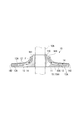
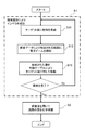
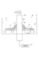
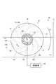
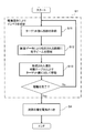
- FIG. 2 is a cross-sectional view taken along the line II-II of the impeller shown in FIG. It is a figure which shows the additive manufacturing apparatus used for manufacture of the impeller shown in FIG. It is a figure which shows schematic structure of the apparatus used for the chemical polishing of the channel wall surface in 1st Embodiment. It is a figure which shows the procedure which manufactures the impeller which concerns on 1st Embodiment. It is a schematic diagram which shows the chemical polishing apparatus which concerns on 2nd Embodiment. It is a schematic diagram which shows the chemical polishing apparatus which concerns on 3rd Embodiment.
- the impeller 10 is provided in a centrifugal rotary machine such as a centrifugal compressor, and is assembled to a rotary shaft 10A (FIG. 2).
- the centrifugal compressor typically includes a plurality of impellers 10 arranged coaxially, and gases such as air are sequentially compressed by the impellers 10.
- the impeller 10 includes a hub 11 through which a rotating shaft 10 ⁇ / b> A passes through a shaft hole 110, a shroud 12 that faces the surface of the hub 11 with a predetermined interval, and a plurality of blades 13. And.
- a plurality of flow paths 14 are formed by partitioning the space between the hub 11 and the shroud 12 with a plurality of blades 13.
- Each flow path 14 is partitioned between the hub 11, the shroud 12, and the adjacent blades 13 and 13.
- the wall 15 that partitions the flow path 14 and contacts the gas is constituted by the hub 11, the shroud 12, and the blade 13.
- each flow path 14 has an inlet 141 positioned on the inner peripheral side of the impeller 10 and an outlet 142 positioned on the outer peripheral side of the impeller 10.
- the blade 13 and the flow path 14 between the blades 13 and 13 have a curved shape with respect to both the radial direction and the axial direction of the impeller 10.
- the impeller 10 is rotated in the direction of the arrow 10R (FIG. 1) by a drive unit (not shown)
- the gas in the flow path 14 is accelerated by centrifugal force, so that the gas is sucked into the flow path 14 from the inlet 141.
- the air is compressed while flowing through the flow path 14 in the direction indicated by the arrow F in FIG.
- the impeller 10 is formed by hot melt additive manufacturing using, for example, low alloy steel, stainless steel, titanium alloy, or the like.
- low alloy steel include Ni—Cr—Mo steel and Cr—Mo steel.
- stainless steel include precipitation hardening type stainless steel, martensitic stainless steel, and duplex stainless steel.
- the surface 15 ⁇ / b> A of the wall 15 of the flow path 14 faces the surface 11 ⁇ / b> A of the hub 11, the inner surface 12 ⁇ / b> A of the shroud 12, the ventral surface 13 ⁇ / b> A of the blade 13. It is composed of a back surface 13B of the blade 13. An abdominal surface 13A of the blade 13 protrudes toward a back surface 13B of the blade 13 adjacent to the blade 13.
- the additive manufacturing apparatus 30 forms the impeller 10 by hot melt additive manufacturing using an electron beam (electron beam) which is a high energy heat source.
- the additive manufacturing apparatus 30 includes an electron beam guide path 31 that guides the electron beam EB toward the target surface Tg, a chamber in which a shaped article W (impeller 10) is formed through melting and solidification caused by irradiation of the electron beam EB. 32 and a control device 33 that controls each part of the additive manufacturing apparatus 30 based on the three-dimensional data.
- the inside of the electron beam guide 31 and the chamber 32 is depressurized to a predetermined degree of vacuum with respect to the external atmospheric pressure. Therefore, oxidation of the material used can be suppressed.
- the electron beam guide 31 has an electron beam generation source 311 that emits an electron beam EB, and a focusing coil 312 and a deflection coil 313 that are arranged around the electron beam EB.
- a target surface Tg to which the electron beam EB is irradiated is set in the internal space of the chamber 32.
- the target surface Tg is a horizontal plane.
- a hopper 34 for supplying the metal powder 201 to the target surface Tg and a movable table 36 for supporting the model W are provided inside the chamber 32.
- a heating device for heating the shaped article W can be provided in the chamber 32 to control the temperature as necessary.
- this apparatus 20 is used, and it grind
- the chemical polishing does not use an electrode, so that it is not necessary to manufacture a curved electrode that follows the shape of the flow path 14 according to the shape of the flow path 14 of the impeller 10 each time.
- the polishing apparatus 20 of the present embodiment stores a polishing liquid 21, a polishing liquid tank 22 that houses the impeller 10, and a path 23 that pumps the polishing liquid 21 from the polishing liquid tank 22 and pumps it. And a supply unit 24 that constitutes the end of the path 23 and supplies the polishing liquid 21 to each of the plurality of flow paths 14 of the impeller 10.
- the polishing apparatus 20 can be provided with an apparatus (not shown) for managing and replenishing the polishing liquid 21 as required.
- the impeller 10 is horizontally supported by a member (not shown).
- the impeller 10 is stably supported so that the outlet 142 is downward and the inlet 141 is upward.
- the axis of the impeller 10 is along the vertical direction.
- the impeller 10 may be disposed so as to be inclined with respect to the horizontal plane as long as the flow applied to the polishing liquid 21 in the flow path 14 is not hindered.
- the polishing liquid 21 is stored in the polishing liquid tank 22 up to a liquid level above the outlet 142 of the flow path 14 of the impeller 10.
- polishing liquid 21 what contains an acid, an alkali, and a salt in a component can be used.
- the surface portion of the wall 15 is dissolved by the oxidation-reduction reaction between the component of the polishing liquid 21 and the wall 15 of the flow path 14.
- a polishing liquid 21 containing 8 wt% H 2 O 2 and 4 wt% NH 4 HF can be used.
- the pumping path 23 includes a pipe 231 connecting the inside of the polishing liquid tank 22 and the supply unit 24, and a pump 232 that pumps the polishing liquid 21 from the polishing liquid tank 22 through the pipe 231 and pumps it.
- a device (not shown) for managing and replenishing the components of the polishing liquid 21 can be provided in the pressure feeding path 23.
- the pipe 231 has an inflow part 23 A for allowing the polishing liquid 21 in the polishing liquid tank 22 to flow in, and an outflow part 23 B for allowing the polishing liquid 21 to flow out to the supply part 24.
- the inflow portion 23 ⁇ / b> A is positioned below the level of the polishing liquid 21 in the polishing liquid tank 22.
- the outflow portion 23B causes the polishing liquid 21 to flow out downward from above the impeller 10.
- the supply unit 24 receives the polishing liquid 21 from the pipe 231 and distributes it to the plurality of flow paths 14 of the impeller 10.
- the supply unit 24 has an internal space 241 that can receive the polishing liquid 21 once and communicate with the inlet 141 of each flow path 14.
- the impeller 10 is manufactured through a molding step S ⁇ b> 1 by hot melt lamination modeling and a chemical polishing step S ⁇ b> 2 using a polishing liquid 21.
- the metal powder 201 as a material is supplied from the hopper 34 to the target surface Tg under the control of the control device 33 of the additive manufacturing apparatus 30 shown in FIG. 3 (powder supply step S11).
- the metal powder 201 is spread on the target surface Tg with a predetermined thickness. If necessary, a rake arm (not shown) that can move in parallel with the target surface Tg can be used.
- the electron beam EB is irradiated only in a range specified in the target surface Tg (electron beam irradiation step S12).
- the focus coil 312 and the deflection coil 313 are electromagnetically controlled by the control device 33, whereby the electron beam EB scans a specific range in the target surface Tg at high speed.
- the metal powder 201 is locally melted at the position where the electron beam EB is incident, and solidifies after the electron beam EB has passed.
- the metal powder 201 before melting can be preheated by an appropriate heating device or an electron beam EB having a low output.
- the layer Ly is formed on the target surface Tg after the metal powder 201 is melted and solidified. Then, the movable table 36 is lowered by the thickness of the layer Ly, and the completed layer Ly is moved so as to be retracted (offset) from the target surface Tg (moving step S13).
- the target surface Tg is set on the surface of the layer Ly formed immediately before.
- each layer Ly is completed. Since the stacked layers Ly are bonded in close contact with each other, the impeller 10 is integrally formed.
- the thickness of each of the multiple layers Ly stacked is constant.
- the thickness of each layer Ly is set to an appropriate value from the range of 10 ⁇ m to 50 ⁇ m, for example.
- the metal powder 201 supplied to the periphery of the modeled object W (impeller 10) and the position corresponding to the inside of the flow path 14 and the shaft hole 110 is not solidified because it is not irradiated with the electron beam EB. Those metal powders 201 can be collected and reused.
- the surface roughness Ra of the wall 15 of the flow path 14 of the impeller 10 molded as described above is, for example, about 25 ⁇ m to 40 ⁇ m.
- surface roughness Ra refers to that based on JIS B 0601-2001.
- the wall 15 is polished to a surface roughness Ra or less required for the surface 15A of the wall 15 of the flow path 14 by the chemical polishing step S2.
- the required surface roughness Ra is, for example, 1.5 ⁇ m to 2.5 ⁇ m. Therefore, as an example, the difference between the surface roughness Ra of the unpolished wall 15 formed by additive manufacturing and the surface roughness Ra of the wall 15 after polishing is, for example, 37.5 ⁇ m or less.
- the pump 232 is operated in a state where the impeller 10 is immersed in the polishing liquid 21, as shown in FIG. Then, the polishing liquid 21 in the polishing liquid tank 22 reaches the supply unit 24 through the pressure feeding path 23 and is supplied to the plurality of flow paths 14 respectively.
- the polishing liquid 21 flows down in each flow path 14 and flows out from the outlet 142 into the polishing liquid tank 22. Since the circuit through which the polishing liquid 21 flows is configured as described above, a flow is given to the polishing liquid 21 in the plurality of flow paths 14.
- the polishing liquid 21 is in contact with the entire surface of the wall 15 of the flow path 14 while flowing, so that the oxidation-reduction reaction between the components of the polishing liquid 21 and the walls 15 of the flow path 14 occurs. It progresses uniformly over the entire surface of the wall 15, and the surface portion of the wall 15 is dissolved and removed. With this, the surface portion of the wall 15 is uniformly polished.
- the entire surface of the wall 15 of the flow path 14 of the impeller 10 is immersed in the polishing liquid 21, and a flow is given to the polishing liquid 21 in the flow path 14.
- the entire surface 15A of the wall 15 including the depth of the flow path 14 can be polished and smoothed.
- the surface roughness Ra of the wall 15 formed by hot melt additive manufacturing is, for example, about 25 to 40 ⁇ m, and the surface roughness of the flow path wall of the impeller formed by casting or electric discharge machining (for example, Compared to about 25 ⁇ m). Therefore, it is possible to easily reach the surface roughness Ra or less required for the wall 15 of the flow path 14 of the impeller 10 by the chemical polishing step S2. Although depending on the composition, concentration, flow rate, etc. of the polishing liquid 21, the surface roughness of the wall 15 can be obtained by simply performing the chemical polishing step S2 for bringing the polishing liquid 21 into contact with the wall 15 while allowing the polishing liquid 21 to flow. To reach.
- polishing unevenness does not occur. Therefore, friction loss can be suppressed.
- polishing the wall surface of the flow path of the impeller formed by a method other than hot melt additive manufacturing to achieve the required surface roughness a long time is required for the chemical polishing step performed under the same conditions. Therefore, a difference in the amount of polishing between a place where the flow rate is fast and a place where the flow rate is fast is likely to occur in the flow path 14, which may cause uneven polishing.
- the impeller 10 is molded by hot melt lamination modeling, and the entire region of the wall 15 of the flow path 14 is immersed in the polishing liquid 21 to which the flow is applied, and chemical polishing is performed, whereby the hot melt lamination is performed.
- the overall manufacturing efficiency from the formation of the impeller 10 to the same surface roughness can be improved.
- it has the meaning that the impeller 10 excellent in performance can be provided at low cost.
- a laser beam can be used as a heat source for melting the metal powder 201 instead of the electron beam EB.
- the layered manufacturing apparatus 30 may be provided with a laser oscillator instead of the electron beam generation source 311.
- the wall 15 of the flow path 14 of the impeller 10 is grind
- the chemical polishing apparatus 40 includes a polishing liquid tank 41 that stores the polishing liquid 21 and accommodates the impeller 10, and a driving device 42 that supports the impeller 10 and rotates it around an axis.
- the impeller 10 In the polishing liquid tank 41, the impeller 10 is arranged horizontally, and the entire wall 15 of the flow path 14 is immersed in the polishing liquid 21. In addition, as long as the flow given to the polishing liquid 21 in the flow path 14 is not hindered, the impeller 10 may be disposed to be inclined with respect to the horizontal plane.
- the driving device 42 supports the impeller 10 disposed in the polishing liquid tank 41 with a jig (not shown) and a shaft 421 and rotates it around the axis. The direction of rotation at this time is the same as the direction of rotation of the impeller 10 used in the centrifugal rotating machine (see arrow 10R in FIG. 1). Moreover, the drive device 42 rotates the impeller 10 at a speed lower than the rotational speed of the impeller 10 when used by being incorporated in a centrifugal rotating machine.
- the impeller 10 is formed by hot melt additive manufacturing, a chemical polishing process is performed using the chemical polishing apparatus 40.
- the impeller 10 is accommodated in the polishing liquid tank 41, and the impeller 10 is rotated around the axis in the direction of the arrow 10R by the driving device 42.
- the polishing liquid 21 enters the flow path 14 from each inlet 141 of the plurality of flow paths 14, flows in the flow path 14, and is polished from the outlet 142. It is discharged into the liquid 21. That is, when the impeller 10 is rotated in the same direction as in use, a flow from the inlet 141 toward the outlet 142 is given to the polishing liquid 21 in the flow path 14.
- each flow path 14 the polishing liquid 21 is in contact with the entire surface of the wall 15 of the flow path 14 while flowing, so that the oxidation-reduction reaction between the components of the polishing liquid 21 and the wall 15 of the flow path 14 It progresses uniformly over the entire surface, and the surface portion of the wall 15 is dissolved and removed. Further, since the hydrogen gas generated by the oxidation-reduction reaction is pushed away by the flow of the polishing liquid 21, it is possible to prevent the polishing from being hindered by the adhesion of the hydrogen gas to the wall 15 and to suppress the occlusion of hydrogen to the wall 15. be able to.
- the surface roughness Ra required for the wall 15 of the flow path 14 of the impeller 10 can be easily reached. Since the removal amount by polishing is small and polishing can be completed in a short time, friction loss can be suppressed without causing polishing unevenness.
- the manufacture of the impeller 10 according to the third embodiment of the present invention will be described.
- the wall 15 of the flow path 14 of the impeller 10 is grind
- the chemical polishing apparatus 50 includes a polishing liquid tank 51 that stores the polishing liquid 21 and accommodates the impeller 10, and a driving device 52 that supports the impeller 10 and rotates it around an axis.
- the impeller 10 is disposed in the polishing liquid tank 51 in a posture in which the axis is along the horizontal direction.
- the impeller 10 may be arranged such that the axis of the impeller 10 is inclined with respect to the horizontal plane as long as the flow of the polishing liquid 21 from the outlet 142 of the flow path 14 toward the inlet 141 is not hindered.
- polishing liquid tank 51 In the polishing liquid tank 51, about half of the impeller 10 is immersed in the polishing liquid 21. It suffices if the polishing liquid 21 is stored in the polishing liquid tank 51 up to a liquid level sufficient to immerse the inlets 141 to the outlets 142 of some of the channels 14.
- the driving device 52 supports the impeller 10 disposed in the polishing liquid tank 51 with a jig (not shown) and a shaft 521, and rotates it around an axis.
- the direction of rotation at this time is opposite to the direction of rotation of the impeller 10 incorporated and used in the centrifugal rotating machine (see arrow R in FIG. 7).
- the driving device 52 rotates the impeller 10 at a speed lower than the rotational speed of the impeller 10 when used by being incorporated in a centrifugal rotating machine.
- the impeller 10 is formed by hot melt additive manufacturing, a chemical polishing process is performed using the chemical polishing apparatus 50.
- the impeller 10 is accommodated in the polishing liquid tank 51, and the impeller 10 is rotated around the axis in the direction of the arrow R by the driving device 52.
- the polishing liquid 21 enters the flow path 14 from the outlet 142 of the flow path 14.
- the polishing liquid 21 flows down toward the inlet 141 while being scooped up by the back surface 13B of the blade 13 (see arrow A in FIG. 7), and is discharged from the inlet 141 into the polishing liquid 21.
- the polishing liquid 21 that has entered the flow path 14 from the outlet 142 of the flow path 14 flows toward the inlet 141 of the flow path 14, so that the polishing liquid 21 contacts the entire surface of the wall 15 of the flow path 14. Therefore, the surface portion of the wall 15 is uniformly dissolved and removed. Further, since the hydrogen gas generated by the oxidation-reduction reaction is pushed away by the flow of the polishing liquid 21, it is possible to prevent the polishing from being hindered by the adhesion of the hydrogen gas to the wall 15 and to suppress the occlusion of hydrogen to the wall 15. be able to.
- the surface roughness Ra required for the wall 15 of the flow path 14 of the impeller 10 can be easily reached. Since the removal amount by polishing is small and polishing can be completed in a short time, friction loss can be suppressed without causing polishing unevenness.
- the manufacture of the impeller 10 according to the fourth embodiment of the present invention will be described.
- the impeller 10 is manufactured by the manufacturing procedure shown in FIG. First, as described in the first embodiment, the molding step S1 by hot melt lamination modeling is performed, and the electroless plating step S3 is performed on the wall 15 of the flow path 14 of the impeller 10 obtained by the molding step S1. . Necessary pretreatment can be performed before the electroless plating step S3.
- the plating solution is brought into contact with the wall 15 of the flow path 14, and the metal ions are reduced and deposited as a metal on the wall 15 by a chemical reaction between the metal ions and the reducing agent in the plating solution.
- Electroless plating does not require an electrode that follows the shape of the flow path 14.
- a plating layer is applied to the wall 15 of the flow path 14 by the electroless plating step S3. If this plating layer is applied with a thickness of, for example, 2.5 ⁇ m to 50 ⁇ m, minute irregularities on the surface of the base material do not appear on the surface of the plating layer. Therefore, a surface roughness smaller than that of the base material surface can be obtained. In addition, the minute irregularities on the surface of the base material and the plating layer are firmly bonded by the anchor effect.
- Usable plating solutions include, for example, those containing nickel and phosphorus (Ni-P plating), those containing nickel and boron (Ni-B plating), and those containing nickel, phosphorus, and boron (Ni -PB plating).
- Ni-P plating nickel and phosphorus
- Ni-B plating nickel and boron
- Ni -PB plating nickel, phosphorus, and boron
- wear resistance and corrosion resistance can be imparted to the wall 15 of the flow path 14.
- the apparatuses 20, 40, and 50 described in the first to third embodiments can be used.
- the polishing liquid tank for storing the polishing liquid 21 may be changed to a plating bath for storing the plating liquid.
- the entire surface of the wall 15 of the flow path 14 can be immersed in the plating solution, and a flow can be given to the plating solution in the flow path 14.
- the plating layer can be formed with a stable quality and a uniform thickness over the entire surface of the 14 walls 15.
- heat treatment can be applied.
- the surface roughness Ra required for the wall 15 of the flow path 14 of the impeller 10 can be easily reduced. Can be reached.
- the manufacture of the impeller 10 according to the fifth embodiment of the present invention will be described.
- the impeller 10 is manufactured by the manufacturing procedure shown in FIG. First, as described in the first embodiment, the molding step S1 by hot melt lamination modeling is performed, and the electroplating step S4 is performed on the wall 15 of the flow path 14 of the impeller 10 obtained by the molding step S1.
- the impeller 10 is used as a cathode, the electrode made of a plating material is used as an anode, and a current is applied between the electrodes in the plating solution, so that metal ions in the plating solution are reduced and deposited on the wall 15 as metal.
- Perform electroplating When the plating layer is applied to the wall 15 of the flow path 14 with a thickness of, for example, 2.5 ⁇ m to 50 ⁇ m by the electroplating step S4, minute irregularities on the surface of the base material do not appear on the surface of the plating layer. Therefore, a surface roughness smaller than that of the base material surface can be obtained. In addition, the minute irregularities on the surface of the base material and the plating layer are firmly bonded by the anchor effect.
- Examples of the plating solution that can be used include those containing nickel and those containing chromium. Depending on the type of plating bath used, wear resistance and corrosion resistance can be imparted to the wall 15 of the flow path 14.
- the surface roughness Ra required for the wall 15 of the flow path 14 of the impeller 10 can be easily reached by electroplating the wall 15 of the flow path 14 of the impeller 10 formed by hot melt additive manufacturing. Can be made.
- the manufacture of the impeller 10 according to the sixth embodiment of the present invention will be described.
- the impeller 10 is manufactured by the manufacturing procedure shown in FIG. First, as explained in the first embodiment, a resin coating process in which a molding process S1 is performed by hot melt additive manufacturing, and a resin film is applied to the wall 15 of the flow path 14 of the impeller 10 obtained by the molding process S1. S5 is performed.
- a liquid resin film material is supplied into the flow path 14 while rotating the impeller 10 around the axis (spin coating).
- spin coating a film having a uniform thickness
- the resin coating does not require an electrode that follows the shape of the flow path 14. If the resin coating is applied to the wall 15 of the flow path 14 with a thickness of, for example, 2.5 ⁇ m to 50 ⁇ m by the resin coating step S5, minute irregularities on the surface of the base material do not appear on the surface of the resin coating. Therefore, a surface roughness smaller than that of the base material surface can be obtained. In addition, the minute irregularities on the surface of the base material and the resin film are firmly bonded by the anchor effect.
- the resin material that can be used examples include a fluorine-based resin, a urethane-based resin, an epoxy-based resin, a phenol-based resin, and an acrylic resin (especially baking acrylic).
- a fluorine-based resin a urethane-based resin
- an epoxy-based resin a phenol-based resin
- an acrylic resin especially baking acrylic.
- wear resistance and corrosion resistance can be imparted to the wall 15 of the flow path 14. Even by applying resin coating to the wall 15 of the flow path 14 of the impeller 10 formed by hot melt additive manufacturing, the surface roughness Ra required for the wall 15 of the flow path 14 of the impeller 10 can be easily reached. Can be made.
- a coating that imparts erosion resistance can be applied to the surface of the wall 15 of the flow path 14 (erosion-resistant coating forming step).
- Such coatings include, for example, WC composites (cermets) mainly containing tungsten carbide (WC), Cr 3 C 2 composites, alumina-titania (AlO 3 —TiO 2 ), chromium oxide ceramics (Cr 2 O). 3 ) etc., and can be formed by chemical vapor deposition or physical vapor deposition.
- the surface roughness of the wall 15 of the flow path 14 of the impeller 10 after the hot melt additive manufacturing is, for example, about 25 ⁇ m to 40 ⁇ m. Therefore, the minute irregularities on the surface of the base material of the impeller 10 and the erosion-resistant coating Are firmly joined by the anchor effect.
- the surface roughness of the base material of the impeller 10 after hot melt additive manufacturing is, for example, about 25 ⁇ m to 40 ⁇ m
- the surface roughness of the erosion-resistant coating covering the surface of the base material is as small as about 10 nm to 800 nm, for example. . Therefore, the surface roughness of the coating can easily reach the surface roughness required for the wall 15 of the flow path 14.
- a step of applying a film that imparts erosion resistance may be sandwiched between the molding step by hot melt additive manufacturing described above and the plating or coating step described in the above embodiments.
- the configuration described in the above embodiment can be selected or changed to another configuration as long as it does not depart from the gist of the present invention.
Landscapes
- Chemical & Material Sciences (AREA)
- Engineering & Computer Science (AREA)
- Materials Engineering (AREA)
- Mechanical Engineering (AREA)
- Chemical Kinetics & Catalysis (AREA)
- Metallurgy (AREA)
- Organic Chemistry (AREA)
- General Engineering & Computer Science (AREA)
- Electrochemistry (AREA)
- General Chemical & Material Sciences (AREA)
- Manufacturing & Machinery (AREA)
- Structures Of Non-Positive Displacement Pumps (AREA)
- Electroplating Methods And Accessories (AREA)
- Other Surface Treatments For Metallic Materials (AREA)
- ing And Chemical Polishing (AREA)
- Chemically Coating (AREA)
Abstract
研磨等により平滑化する工程に要する時間を抑えて、インペラの成形から平滑化までを含めた製造効率を改善すること。本発明のインペラの製造方法は、熱溶融積層造形によりインペラ10を成形する成形工程S1と、インペラ10が有する流路14を区画する壁15を研磨液21と接触させて研磨する化学研磨工程S2とを備える。化学研磨工程S2では、流路14内の研磨液21に流動を与える。化学研磨工程S2では、研磨液21を貯留し、インペラ10を収容する研磨液槽22と、研磨液槽22内の研磨液21を圧送する経路23と、経路23の終端を構成し、研磨液21を複数の流路14の各々の入口141に供給する供給部24とを備えた装置を用いて流路14内の研磨液21に流動を与えることが好ましい。
Description
本発明は、インペラの製造方法に関する。
特に、湿式研磨等により平滑化処理を行うインペラ製造方法に関する。
特に、湿式研磨等により平滑化処理を行うインペラ製造方法に関する。
遠心圧縮機、遠心送風機、遠心ポンプ等の遠心回転機に、ハブと、シュラウドと、複数のブレードとを備えたインペラ(羽根車)が使用されている。
インペラには、ハブと、シュラウドと、隣り合うブレードとで囲まれた流路が形成されている。この流路は、圧縮効率等を考慮して、3次元的に湾曲した複雑な形状に設計されている。インペラには、一般に、高い形状精度と、表面粗さが微小であることが要求される。
インペラには、ハブと、シュラウドと、隣り合うブレードとで囲まれた流路が形成されている。この流路は、圧縮効率等を考慮して、3次元的に湾曲した複雑な形状に設計されている。インペラには、一般に、高い形状精度と、表面粗さが微小であることが要求される。
インペラの製造方法に関し、複数の部位に分割して製作されたピース同士を溶接することが従来行われてきたが、溶接品質の確保が難しいので、近年では、金属材料の塊から放電加工により一体成形することが多い。放電加工の際には、流路の形状に合わせた電極を使用して流路を彫り進める。放電加工を行うと、表面に形成された変質層を、例えば酸洗により除去しなくてはならない。
ところで、流体の流速エネルギーを圧力エネルギーに変換するインペラには、摩擦損失を抑えて所定の圧縮効率を実現するために、流路の壁面の高い平滑性が要求される。流路の壁面に要求される表面粗さは非常に小さい。
そのため、成形されたインペラの流路壁面を表面粗さの要求値にまで仕上げる研磨工程が不可欠である(特許文献1,2)。
特許文献1では、インペラの流路内に、流路に倣う形状の研磨用ノズル部材を挿入し、ノズル部材に形成された孔から流路の壁面に向けて研磨液を噴出している。
特許文献2では、インペラを研磨液に浸漬し、流路内に挿入されたノズル部材の孔から研磨液を吸引している。特許文献1,2のいずれも、研磨液とインペラに用いられた金属との化学反応により発生する水素ガスの気泡を、ノズル部材の孔を通る研磨液の噴流エネルギーにより流路の壁面から剥がすことで、研磨加工面のうねりを防いで平滑化を図っている。
そのため、成形されたインペラの流路壁面を表面粗さの要求値にまで仕上げる研磨工程が不可欠である(特許文献1,2)。
特許文献1では、インペラの流路内に、流路に倣う形状の研磨用ノズル部材を挿入し、ノズル部材に形成された孔から流路の壁面に向けて研磨液を噴出している。
特許文献2では、インペラを研磨液に浸漬し、流路内に挿入されたノズル部材の孔から研磨液を吸引している。特許文献1,2のいずれも、研磨液とインペラに用いられた金属との化学反応により発生する水素ガスの気泡を、ノズル部材の孔を通る研磨液の噴流エネルギーにより流路の壁面から剥がすことで、研磨加工面のうねりを防いで平滑化を図っている。
放電加工等により成形されたインペラの表面を表面粗さの要求値に研磨することはできても、その研磨工程に時間が掛かる。
研磨工程が長時間に及ぶと、流路内の研磨液の流れの速いところと遅いところとで研磨量に相違が生じ、それが研磨のムラに繋がってしまう。
研磨工程が長時間に及ぶと、流路内の研磨液の流れの速いところと遅いところとで研磨量に相違が生じ、それが研磨のムラに繋がってしまう。
以上より、本発明は、研磨等により平滑化する工程に要する時間を抑えて、インペラの成形から平滑化までを含めた製造効率を改善することを目的とする。
インペラへの要望は、適用される遠心回転機械の仕様等に応じて多岐にわたり、しかも増え続けている。
勿論、コストの抑制も望まれている。インペラの放電加工には、流路の形状に合わせた電極が必要であり、放電加工用の電極がコストアップの要因となる。
そのような状況下で、本発明の発明者らは、金属粉体を用いる熱溶融積層造形に着目した。熱溶融積層造形は、金型を用いず、断面データに基づいて金属粉体を溶融、凝固させた層を積層することにより、3次元の部材を成形する技術である。金型を用いないので、形状変更等に対応し易く、コストも抑えられる。
現状、熱源として電子ビームを用いる積層造形によりインペラを一体成形することが提案されている(特許文献3)。
勿論、コストの抑制も望まれている。インペラの放電加工には、流路の形状に合わせた電極が必要であり、放電加工用の電極がコストアップの要因となる。
そのような状況下で、本発明の発明者らは、金属粉体を用いる熱溶融積層造形に着目した。熱溶融積層造形は、金型を用いず、断面データに基づいて金属粉体を溶融、凝固させた層を積層することにより、3次元の部材を成形する技術である。金型を用いないので、形状変更等に対応し易く、コストも抑えられる。
現状、熱源として電子ビームを用いる積層造形によりインペラを一体成形することが提案されている(特許文献3)。
ここで、熱溶融積層造形により成形されたインペラの流路の壁の表面粗さは、鋳造や放電加工により成形されたインペラの流路の壁の表面粗さ(例えば表面粗さRaが25μm程度)と比べて悪くない。
そこでなされた本発明のインペラの製造方法は、熱溶融積層造形によりインペラを成形する成形工程と、インペラが有する流路を区画する壁を研磨液と接触させて研磨する化学研磨工程と、を備え、化学研磨工程では、流路内の研磨液に流動を与えることを特徴とする。
本明細書において「熱溶融積層造形」は、3次元データを構成する断面データに基づいて、所定のターゲット面に供給された粉体を溶融させ、その後に凝固させることで形成される層を順次積層することによって3次元の部材を成形することをいうものとする。
本発明のインペラ製造方法において、化学研磨工程では、研磨液を貯留し、インペラを収容する研磨液槽と、研磨液槽内の研磨液を圧送する経路と、経路の終端を構成し、研磨液を複数の流路の各々の入口に供給する供給部と、を備えた装置を用いて、流路内の研磨液に流動を与えることが好ましい。
本発明のインペラ製造方法において、化学研磨工程では、研磨液に浸漬された状態でインペラを使用時の回転の向きと同じ向きに回転させることで、流路の入口から出口に向かう流動を流路内の研磨液に与えることが好ましい。
本発明のインペラ製造方法において、化学研磨工程では、研磨液に浸漬された状態でインペラを使用時の回転の向きとは逆向きに回転させることで、流路の出口から流路内に入り込んだ研磨液を流路の入口に向けて流すことが好ましい。
本発明のインペラの製造方法は、熱溶融積層造形によりインペラを成形する成形工程と、インペラが有する流路を区画する壁にめっき液を接触させて無電解めっきを施す無電解めっき工程と、を備え、無電解めっき工程では、流路内のめっき液に流動を与えることを特徴とする。
本発明のインペラ製造方法において、無電解めっき工程では、めっき液を貯留し、インペラを収容するめっき液槽と、めっき液槽内のめっき液を圧送する経路と、経路の終端を構成し、めっき液を複数の流路の各々の入口に供給する供給部と、を備えた装置を用いて、流路内のめっき液に流動を与えることが好ましい。
本発明のインペラ製造方法において、無電解めっき工程では、めっき液に浸漬された状態でインペラを使用時の回転の向きと同じ向きに回転させることで、流路の入口から出口に向かう流動を流路内のめっき液に与えることが好ましい。
本発明のインペラ製造方法において、無電解めっき工程では、めっき液に浸漬された状態でインペラを使用時の回転の向きとは逆向きに回転させることで、流路の出口から流路内に入り込んだめっき液を流路の入口に向けて流すことが好ましい。
本発明のインペラの製造方法は、熱溶融積層造形によりインペラを成形する成形工程と、インペラが有する流路を区画する壁に電気めっきを施す電気めっき工程と、を備えることを特徴とする。
本発明のインペラの製造方法は、熱溶融積層造形によりインペラを成形する成形工程と、インペラが有する流路を区画する壁に樹脂材料を用いて被膜を施す被膜処理工程と、を備えることを特徴とする。
本発明のインペラの製造方法は、熱溶融積層造形によりインペラを成形する成形工程と、インペラが有する流路を区画する壁に耐エロージョン性を付与する被膜を施す耐エロージョン被膜形成工程と、を備えることを特徴とする。
本発明によれば、化学研磨、無電解めっき、電気めっき、および樹脂被膜処理のいずれかによって、流路の壁の表面全域に亘り平滑化することができる。
ここで、熱溶融積層造形により成形された壁の表面粗さに基づけば、上記のいずれかの平滑化工程により、インペラの流路の壁に要求される表面粗さ以下に容易に到達させることができる。
したがって、熱溶融積層造形によりインペラを成形する成形工程と、そのインペラの流路の壁を平滑化する工程とを備えた本発明によれば、熱溶融積層造形以外の方法で成形されたインペラの流路の壁を平滑化する場合と比べて、インペラの成形から、同じ表面粗さに平滑化するまでの全体の製造効率を改善することができる。
ここで、熱溶融積層造形により成形された壁の表面粗さに基づけば、上記のいずれかの平滑化工程により、インペラの流路の壁に要求される表面粗さ以下に容易に到達させることができる。
したがって、熱溶融積層造形によりインペラを成形する成形工程と、そのインペラの流路の壁を平滑化する工程とを備えた本発明によれば、熱溶融積層造形以外の方法で成形されたインペラの流路の壁を平滑化する場合と比べて、インペラの成形から、同じ表面粗さに平滑化するまでの全体の製造効率を改善することができる。
以下、添付図面を参照しながら、本発明の実施形態について説明する。
〔第1実施形態〕
まず、図1および図2を参照し、インペラ10の基本的な構成を簡単に説明する。
インペラ10は、遠心圧縮機等の遠心回転機械に備えられており、回転軸10A(図2)に組み付けられる。
遠心圧縮機は、典型的には、同軸に配置される複数のインペラ10を備えており、それらのインペラ10によりエア等の気体が順次圧縮される。
〔第1実施形態〕
まず、図1および図2を参照し、インペラ10の基本的な構成を簡単に説明する。
インペラ10は、遠心圧縮機等の遠心回転機械に備えられており、回転軸10A(図2)に組み付けられる。
遠心圧縮機は、典型的には、同軸に配置される複数のインペラ10を備えており、それらのインペラ10によりエア等の気体が順次圧縮される。
インペラ10は、図1および図2に示すように、軸孔110に回転軸10Aが通されるハブ11と、ハブ11の表面に所定の間隔をおいて対向するシュラウド12と、複数のブレード13とを備えている。ハブ11とシュラウド12との間の空間が複数のブレード13で仕切られることにより、複数の流路14(図1)が形成されている。
各流路14は、ハブ11と、シュラウド12と、隣り合うブレード13,13との間に区画されている。流路14を区画していて、気体が接触する壁15は、ハブ11と、シュラウド12と、ブレード13とにより構成されている。
各流路14は、図2に示すように、インペラ10の内周側に位置する入口141と、インペラ10の外周側に位置する出口142とを有している。
各流路14は、ハブ11と、シュラウド12と、隣り合うブレード13,13との間に区画されている。流路14を区画していて、気体が接触する壁15は、ハブ11と、シュラウド12と、ブレード13とにより構成されている。
各流路14は、図2に示すように、インペラ10の内周側に位置する入口141と、インペラ10の外周側に位置する出口142とを有している。
ブレード13と、ブレード13,13間の流路14は、図1および図2に示すように、インペラ10の径方向および軸方向のいずれに対しても湾曲した形状となっている。
インペラ10が、図示しない駆動部により、矢印10R(図1)の向きに回転されると、流路14内の気体が遠心力により加速されるため、入口141から流路14内に気体が吸入され、図1に矢印Fで示す向きに流路14を流れつつ圧縮され、出口142から排出される。
インペラ10が、図示しない駆動部により、矢印10R(図1)の向きに回転されると、流路14内の気体が遠心力により加速されるため、入口141から流路14内に気体が吸入され、図1に矢印Fで示す向きに流路14を流れつつ圧縮され、出口142から排出される。
インペラ10は、例えば、低合金鋼、ステンレス鋼、チタン合金等を用いて熱溶融積層造形により成形されている。
低合金鋼は、例えば、Ni-Cr-Mo鋼、Cr-Mo鋼等である。ステンレス鋼は、例えば、析出硬化型ステンレス鋼、マルテンサイト系ステンレス鋼、二相ステンレス鋼等である。
低合金鋼は、例えば、Ni-Cr-Mo鋼、Cr-Mo鋼等である。ステンレス鋼は、例えば、析出硬化型ステンレス鋼、マルテンサイト系ステンレス鋼、二相ステンレス鋼等である。
流路14の壁15における摩擦損失を抑えるため、壁15の表面15Aには高い平滑性が要求される。そのため、成形されたインペラ10の流路14の壁15を研磨することで、表面粗さの要求値にまで仕上げている。
図1および図2に示すように、流路14の壁15の表面15Aは、ハブ11の表面11Aと、シュラウド12の内側の面12Aと、ブレード13の腹側の面13Aと、それに対向するブレード13の背側の面13Bとから構成されている。ブレード13の腹側の面13Aが、そのブレード13の隣りのブレード13の背側の面13Bに向けて突き出している。
図3を参照し、インペラ10の成形に用いることのできる積層造形装置30について説明する。
積層造形装置30は、高エネルギーの熱源である電子ビーム(電子線)を使用した熱溶融積層造形により、インペラ10を成形する。
積層造形装置30は、電子ビームEBをターゲット面Tgに向けて導く電子ビーム導路31と、電子ビームEBの照射により起こる溶融と、凝固とを経て造形物W(インペラ10)が成形されるチャンバ32と、3次元データに基づいて積層造形装置30の各部を制御する制御装置33とを備えている。
電子ビーム導路31およびチャンバ32の内部は、外部の大気圧に対して所定の真空度にまで減圧されている。そのため、使用材料の酸化を抑えることができる。
積層造形装置30は、高エネルギーの熱源である電子ビーム(電子線)を使用した熱溶融積層造形により、インペラ10を成形する。
積層造形装置30は、電子ビームEBをターゲット面Tgに向けて導く電子ビーム導路31と、電子ビームEBの照射により起こる溶融と、凝固とを経て造形物W(インペラ10)が成形されるチャンバ32と、3次元データに基づいて積層造形装置30の各部を制御する制御装置33とを備えている。
電子ビーム導路31およびチャンバ32の内部は、外部の大気圧に対して所定の真空度にまで減圧されている。そのため、使用材料の酸化を抑えることができる。
電子ビーム導路31は、電子ビームEBを放出する電子ビーム発生源311と、いずれも電子ビームEBの周りに配置される焦点コイル312および偏向コイル313を有している。
チャンバ32の内部空間には、電子ビームEBが照射されるターゲット面Tgが設定されている。ターゲット面Tgは水平な平面である。
チャンバ32の内部には、金属粉体201をターゲット面Tgに供給するホッパ34と、造形物Wを支持する可動テーブル36とが備えられている。
造形物Wの残留応力を考慮し、必要に応じて、造形物Wを加熱する加熱装置をチャンバ32内に設けて温度制御を行うことができる。
チャンバ32の内部空間には、電子ビームEBが照射されるターゲット面Tgが設定されている。ターゲット面Tgは水平な平面である。
チャンバ32の内部には、金属粉体201をターゲット面Tgに供給するホッパ34と、造形物Wを支持する可動テーブル36とが備えられている。
造形物Wの残留応力を考慮し、必要に応じて、造形物Wを加熱する加熱装置をチャンバ32内に設けて温度制御を行うことができる。
次に、図4を参照し、インペラ10の流路14の壁15の研磨に用いることのできる装置20について説明する。本実施形態では、この装置20を使用し、流路14の壁15を研磨液と接触させて化学反応を生じさせることで研磨する(化学研磨)。化学研磨は、電界研磨とは違って電極を使用しないので、流路14の形状に倣う湾曲した電極を、インペラ10の流路14の形状に合わせてその都度製作する必要がない。
本実施形態の研磨装置20は、図4に示すように、研磨液21を貯留し、インペラ10を収容する研磨液槽22と、研磨液槽22内から研磨液21を汲み上げて圧送する経路23と、経路23の終端を構成し、研磨液21をインペラ10の複数の流路14のそれぞれに供給する供給部24とを備えている。
研磨装置20には、研磨液21の管理や補充を行う図示しない装置を必要に応じて設けることができる。
研磨装置20には、研磨液21の管理や補充を行う図示しない装置を必要に応じて設けることができる。
研磨液槽22内で、インペラ10は図示しない部材により水平に支持されている。出口142が下、入口141が上となる向きで、インペラ10は安定して支持されており、インペラ10の軸線は鉛直方向に沿っている。なお、後述するように流路14内の研磨液21に与えられる流動が妨げられない限り、インペラ10が水平面に対して傾斜して配置されていてもよい。
研磨液21は、インペラ10の流路14の出口142よりも上方の液位にまで研磨液槽22内に貯留されている。
研磨液21は、インペラ10の流路14の出口142よりも上方の液位にまで研磨液槽22内に貯留されている。
研磨液21としては、酸、アルカリ、および塩を成分に含むものを用いることができる。研磨液21の成分と流路14の壁15との酸化還元反応により、壁15の表面部分が溶解されることで研磨される。インペラ10に炭素鋼が用いられている場合は、研磨液21として、例えば、H2O2を8wt%およびNH4HFを4wt%含むものを用いることができる。
圧送経路23は、研磨液槽22内と供給部24とを結ぶ配管231と、配管231を通じて研磨液21を研磨液槽22から汲み上げて圧送するポンプ232とを備えている。
研磨液21の成分の管理や補充を行う図示しない装置を圧送経路23に設けることもできる。
研磨液21の成分の管理や補充を行う図示しない装置を圧送経路23に設けることもできる。
配管231は、研磨液槽22内の研磨液21を流入させる流入部23Aと、供給部24へと研磨液21を流出させる流出部23Bとを有している。
流入部23Aは、研磨液槽22内の研磨液21の液位よりも下方に位置している。
流出部23Bは、インペラ10よりも上方から研磨液21を下方に向けて流出させる。
流入部23Aは、研磨液槽22内の研磨液21の液位よりも下方に位置している。
流出部23Bは、インペラ10よりも上方から研磨液21を下方に向けて流出させる。
供給部24は、配管231から研磨液21を受け入れ、インペラ10の複数の流路14に分配する。供給部24は、研磨液21を一旦受け入れ可能であって各流路14の入口141に通じている内部空間241を有している。
研磨液槽22内の研磨液21が圧送経路23により汲み上げられて供給部24によりインペラ10の流路14に供給されるので、インペラ10の全体が研磨液21に浸漬されていない場合であっても、流路14の壁15の表面15Aの全域が研磨液21に接触している。
以下、インペラ10を製造する方法について説明する。
インペラ10は、図5に示すように、熱溶融積層造形による成形工程S1と、研磨液21を用いる化学研磨工程S2とを経て製造される。
まず、成形工程S1では、図3に示す積層造形装置30の制御装置33による制御の下、ホッパ34からターゲット面Tgへと、材料である金属粉体201を供給する(粉体供給ステップS11)。金属粉体201は、所定の厚みでターゲット面Tgに敷き詰められる。必要に応じて、ターゲット面Tgと平行に移動可能なレーキアーム(図示しない)を使用することができる。
インペラ10は、図5に示すように、熱溶融積層造形による成形工程S1と、研磨液21を用いる化学研磨工程S2とを経て製造される。
まず、成形工程S1では、図3に示す積層造形装置30の制御装置33による制御の下、ホッパ34からターゲット面Tgへと、材料である金属粉体201を供給する(粉体供給ステップS11)。金属粉体201は、所定の厚みでターゲット面Tgに敷き詰められる。必要に応じて、ターゲット面Tgと平行に移動可能なレーキアーム(図示しない)を使用することができる。
続いて、断面データに基づいて、ターゲット面Tg内に特定された範囲にだけ電子ビームEBを照射する(電子ビーム照射ステップS12)。このとき、制御装置33により焦点コイル312および偏向コイル313が電磁的に制御されることにより、ターゲット面Tg内における特定範囲を電子ビームEBが高速で走査する。金属粉体201は、電子ビームEBが入射した位置で局所的に溶融し、電子ビームEBが通過した後に凝固する。
適宜な加熱装置あるいは出力の低い電子ビームEBにより、溶融する前の金属粉体201を予熱することもできる。
適宜な加熱装置あるいは出力の低い電子ビームEBにより、溶融する前の金属粉体201を予熱することもできる。
ターゲット面Tg内において特定された範囲の全域への電子ビームEBの照射を終えたならば、金属粉体201の溶融および凝固を経て、ターゲット面Tgに層Lyが形成されている。
そして、可動テーブル36を層Lyの厚みの分だけ下げて、完成した層Lyをターゲット面Tgから退避(オフセット)させるように移動させる(移動ステップS13)。ターゲット面Tgは、直前に形成された層Lyの表面に設定されることとなる。
そして、可動テーブル36を層Lyの厚みの分だけ下げて、完成した層Lyをターゲット面Tgから退避(オフセット)させるように移動させる(移動ステップS13)。ターゲット面Tgは、直前に形成された層Lyの表面に設定されることとなる。
以上のステップS11~S13を、各層Lyの積層が完了するまで繰り返す。積層された層Lyは互いに密着した状態に結合されているため、インペラ10が一体に成形される。
積層される複数の層Lyの各々の厚みは一定である。各層Lyの厚みは、例えば、10μm~50μmの範囲から、適宜な値に定められる。
造形物W(インペラ10)の周囲や、流路14および軸孔110の内側に相当する位置に供給された金属粉体201は、電子ビームEBが照射されていないため凝固していない。それらの金属粉体201を回収し、再度利用することができる。
以上により成形されたインペラ10の流路14の壁15の表面粗さRaは、例えば、25μm~40μm程度である。
本明細書において「表面粗さRa」は、JIS B 0601-2001に基づくものをいう。
積層される複数の層Lyの各々の厚みは一定である。各層Lyの厚みは、例えば、10μm~50μmの範囲から、適宜な値に定められる。
造形物W(インペラ10)の周囲や、流路14および軸孔110の内側に相当する位置に供給された金属粉体201は、電子ビームEBが照射されていないため凝固していない。それらの金属粉体201を回収し、再度利用することができる。
以上により成形されたインペラ10の流路14の壁15の表面粗さRaは、例えば、25μm~40μm程度である。
本明細書において「表面粗さRa」は、JIS B 0601-2001に基づくものをいう。
次に、化学研磨工程S2により、流路14の壁15の表面15Aに要求される表面粗さRa以下にまで壁15を研磨する。要求される表面粗さRaは、例えば、1.5μm~2.5μmである。したがって、一例として、積層造形により成形された未研磨の壁15の表面粗さRaと、研磨後の壁15の表面粗さRaとの差は、例えば、37.5μm以下である。
化学研磨工程S2では、図4に示すように、研磨液21にインペラ10が浸漬された状態で、ポンプ232を作動させる。すると、研磨液槽22内の研磨液21が圧送経路23を通じて供給部24へと至り、複数の流路14にそれぞれ供給される。研磨液21は、各流路14内を流れ落ちて出口142から研磨液槽22内へと流出する。以上のように研磨液21が流れる回路が構成されていることにより、複数の流路14内の研磨液21には流動が与えられている。複数の流路14のそれぞれにおいて、研磨液21が流動しながら流路14の壁15の表面全体に接触しているので、研磨液21の成分と流路14の壁15との酸化還元反応が壁15の表面全域に亘り均一に進行し、壁15の表面部分が溶解されて除去される。これをもって壁15の表面部分が均一に研磨される。
研磨液21の成分と壁15との酸化還元反応に伴い、研磨液21中に水素ガスの気泡が発生するが、研磨液21の流れにより水素ガスの気泡が押し流されるので、水素ガスの壁15への付着を避け、研磨液21を流路14の壁15に均一に接触させることができる。そのため、流路14の壁15の表面にうねりが生じず、壁面が平滑化される。
また、研磨液21の流れにより水素ガスの気泡が押し流されることで、壁15への水素吸蔵を抑止することができる。
また、研磨液21の流れにより水素ガスの気泡が押し流されることで、壁15への水素吸蔵を抑止することができる。
インペラ10の流路14が複雑な形状に構成されているとしても、インペラ10の流路14の壁15の表面全域を研磨液21に浸漬し、流路14内の研磨液21に流動が与えられていることにより、流路14の奥も含め、壁15の表面15A全体を研磨して平滑化することができる。
上述したように、熱溶融積層造形により成形された壁15の表面粗さRaは例えば、25~40μm程度であり、鋳造や放電加工により成形されたインペラの流路の壁の表面粗さ(例えば25μm程度)と比べて悪くない。
そのため、化学研磨工程S2により、インペラ10の流路14の壁15に要求される表面粗さRa以下に容易に到達させることができる。
研磨液21の成分や濃度、流速等にもよるが、研磨液21に流動を与えながら壁15に接触させる化学研磨工程S2を例えば1時間程度行うだけで、壁15の表面粗さが要求値に到達する。
研磨による除去量が僅かであり、研磨を短時間で終えることができるため、流路14内において研磨液21の流速の速いところと遅いところとがあるとしても、研磨ムラが生じない。そのため摩擦損失を抑えることができる。
熱溶融積層造形以外の方法により成形されたインペラの流路の壁面を研磨して表面粗さの要求値にまで研磨する場合には、同様の条件で行う化学研磨の工程に長時間を要する。そのため、流路14内において流速の速いところと遅いところとの研磨量の差が生じ易いので、研磨ムラが発生するおそれがある。
本実施形態によれば、熱溶融積層造形によりインペラ10を成形するとともに、流動が与えられた研磨液21に流路14の壁15の全域を浸漬させて化学研磨を行うことにより、熱溶融積層造形以外の方法により成形されたインペラの流路の壁を化学研磨する場合と比べて、インペラ10の成形から、同じ表面粗さに研磨するまでの全体の製造効率を改善できる。そして、性能の優れたインペラ10を低コストで提供できるという意義を有する。
そのため、化学研磨工程S2により、インペラ10の流路14の壁15に要求される表面粗さRa以下に容易に到達させることができる。
研磨液21の成分や濃度、流速等にもよるが、研磨液21に流動を与えながら壁15に接触させる化学研磨工程S2を例えば1時間程度行うだけで、壁15の表面粗さが要求値に到達する。
研磨による除去量が僅かであり、研磨を短時間で終えることができるため、流路14内において研磨液21の流速の速いところと遅いところとがあるとしても、研磨ムラが生じない。そのため摩擦損失を抑えることができる。
熱溶融積層造形以外の方法により成形されたインペラの流路の壁面を研磨して表面粗さの要求値にまで研磨する場合には、同様の条件で行う化学研磨の工程に長時間を要する。そのため、流路14内において流速の速いところと遅いところとの研磨量の差が生じ易いので、研磨ムラが発生するおそれがある。
本実施形態によれば、熱溶融積層造形によりインペラ10を成形するとともに、流動が与えられた研磨液21に流路14の壁15の全域を浸漬させて化学研磨を行うことにより、熱溶融積層造形以外の方法により成形されたインペラの流路の壁を化学研磨する場合と比べて、インペラ10の成形から、同じ表面粗さに研磨するまでの全体の製造効率を改善できる。そして、性能の優れたインペラ10を低コストで提供できるという意義を有する。
本実施形態において、金属粉体201を溶融させる熱源として、電子ビームEBに代えて、レーザービームを用いることもできる。その場合は、積層造形装置30に、電子ビーム発生源311に代えてレーザー発振器を備えればよい。
〔第2実施形態〕
次に、本発明の第2実施形態に係るインペラ10の製造について説明する。
第2実施形態(第3実施形態も)は、熱溶融積層造形により成形されたインペラ10の流路14の壁15を研磨する際に、流路14内に流動を与える方法が第1実施形態とは相違する。その他は第1実施形態と同様である。
次に、本発明の第2実施形態に係るインペラ10の製造について説明する。
第2実施形態(第3実施形態も)は、熱溶融積層造形により成形されたインペラ10の流路14の壁15を研磨する際に、流路14内に流動を与える方法が第1実施形態とは相違する。その他は第1実施形態と同様である。
第2実施形態では、図6に示す化学研磨装置40を用いて、インペラ10の流路14の壁15を研磨する。
化学研磨装置40は、研磨液21を貯留し、インペラ10を収容する研磨液槽41と、インペラ10を支持して軸周りに回転させる駆動装置42とを備えている。
化学研磨装置40は、研磨液21を貯留し、インペラ10を収容する研磨液槽41と、インペラ10を支持して軸周りに回転させる駆動装置42とを備えている。
研磨液槽41内で、インペラ10は水平に配置され、流路14の壁15の全域が研磨液21に浸漬されている。なお、流路14内の研磨液21に与えられる流動が妨げられない限り、インペラ10が水平面に対して傾斜して配置されていてもよい。
駆動装置42は、研磨液槽41内に配置されたインペラ10を図示しない治具とシャフト421とで支持し、軸周りに回転させる。このときの回転の向きは、遠心回転機械に組み込まれて使用されるインペラ10の回転の向きと同じである(図1の矢印10R参照)。
また、駆動装置42は、遠心回転機械に組み込まれて使用されるときのインペラ10の回転速度よりも低い速度でインペラ10を回転させる。
駆動装置42は、研磨液槽41内に配置されたインペラ10を図示しない治具とシャフト421とで支持し、軸周りに回転させる。このときの回転の向きは、遠心回転機械に組み込まれて使用されるインペラ10の回転の向きと同じである(図1の矢印10R参照)。
また、駆動装置42は、遠心回転機械に組み込まれて使用されるときのインペラ10の回転速度よりも低い速度でインペラ10を回転させる。
インペラ10が熱溶融積層造形により成形されたならば、化学研磨装置40を用いて化学研磨工程を行う。
化学研磨工程では、研磨液槽41内にインペラ10を収容し、駆動装置42により、インペラ10を軸周りに、矢印10Rの向きに回転させる。
研磨液槽41内でインペラ10が回転されるのに伴い、複数の流路14の各々の入口141からそれぞれ研磨液21が流路14内に入り込み、流路14内を流れて出口142から研磨液21中に排出される。つまり、インペラ10が使用時と同じ向きに回転されることで、入口141から出口142に向かう流動が流路14内の研磨液21に与えられる。
化学研磨工程では、研磨液槽41内にインペラ10を収容し、駆動装置42により、インペラ10を軸周りに、矢印10Rの向きに回転させる。
研磨液槽41内でインペラ10が回転されるのに伴い、複数の流路14の各々の入口141からそれぞれ研磨液21が流路14内に入り込み、流路14内を流れて出口142から研磨液21中に排出される。つまり、インペラ10が使用時と同じ向きに回転されることで、入口141から出口142に向かう流動が流路14内の研磨液21に与えられる。
各流路14において、研磨液21が流動しながら流路14の壁15の表面全体に接触しているので、研磨液21の成分と流路14の壁15との酸化還元反応が壁15の表面全域に亘り均一に進行し、壁15の表面部分が溶解されて除去される。
また、酸化還元反応に伴い発生した水素ガスが研磨液21の流れにより押し流されるので、壁15への水素ガスの付着により研磨が妨げられることを避けられるとともに、壁15への水素吸蔵を抑止することができる。
また、酸化還元反応に伴い発生した水素ガスが研磨液21の流れにより押し流されるので、壁15への水素ガスの付着により研磨が妨げられることを避けられるとともに、壁15への水素吸蔵を抑止することができる。
第2実施形態の研磨方法によっても、インペラ10の流路14の壁15に要求される表面粗さRa以下に容易に到達させることができる。研磨による除去量が僅かであり、研磨を短時間で終えることができるため、研磨ムラを生じさせないで摩擦損失を抑えることができる。
〔第3実施形態〕
次に、本発明の第3実施形態に係るインペラ10の製造について説明する。
第3実施形態では、図7に示す化学研磨装置50を用いて、インペラ10の流路14の壁15を研磨する。
化学研磨装置50は、研磨液21を貯留し、インペラ10を収容する研磨液槽51と、インペラ10を支持して軸周りに回転させる駆動装置52とを備えている。
次に、本発明の第3実施形態に係るインペラ10の製造について説明する。
第3実施形態では、図7に示す化学研磨装置50を用いて、インペラ10の流路14の壁15を研磨する。
化学研磨装置50は、研磨液21を貯留し、インペラ10を収容する研磨液槽51と、インペラ10を支持して軸周りに回転させる駆動装置52とを備えている。
第2実施形態とは異なり、インペラ10は、軸線が水平方向に沿った姿勢で研磨液槽51内に配置される。なお、流路14の出口142から入口141に向かう研磨液21の流れが妨げられない限り、インペラ10の軸線が水平面に対して傾斜する向きでインペラ10が配置されていてもよい。
研磨液槽51内では、インペラ10の半分程度が研磨液21に浸漬されている。一部の流路14の入口141から出口142までを浸漬させるのに足りる液位にまで、研磨液槽51内に研磨液21が貯留されていればよい。
駆動装置52は、研磨液槽51内に配置されたインペラ10を図示しない治具とシャフト521とで支持し、軸周りに回転させる。このときの回転の向きは、遠心回転機械に組み込まれて使用されるインペラ10の回転の向きとは逆である(図7の矢印R参照)。
また、駆動装置52は、遠心回転機械に組み込まれて使用されるときのインペラ10の回転速度よりも低い速度でインペラ10を回転させる。
また、駆動装置52は、遠心回転機械に組み込まれて使用されるときのインペラ10の回転速度よりも低い速度でインペラ10を回転させる。
インペラ10が熱溶融積層造形により成形されたならば、化学研磨装置50を用いて化学研磨工程を行う。
その化学研磨工程では、研磨液槽51内にインペラ10を収容し、駆動装置52により、インペラ10を軸周りに、矢印Rの向きに回転させる。
研磨液槽51内でインペラ10が回転されるのに伴い、流路14の出口142から研磨液21が流路14内に入り込む。そして、研磨液21は、ブレード13の背側の面13Bによりすくい上げられながら入口141に向けて流れ落ち(図7の矢印Aを参照)、入口141から研磨液21中に排出される。
その化学研磨工程では、研磨液槽51内にインペラ10を収容し、駆動装置52により、インペラ10を軸周りに、矢印Rの向きに回転させる。
研磨液槽51内でインペラ10が回転されるのに伴い、流路14の出口142から研磨液21が流路14内に入り込む。そして、研磨液21は、ブレード13の背側の面13Bによりすくい上げられながら入口141に向けて流れ落ち(図7の矢印Aを参照)、入口141から研磨液21中に排出される。
上記のように流路14の出口142から流路14内に入り込んだ研磨液21を流路14の入口141に向けて流すことにより、研磨液21が流路14の壁15の表面全体に接触するので、壁15の表面部分が均一に溶解されて除去される。
また、酸化還元反応に伴い発生した水素ガスが研磨液21の流れにより押し流されるので、壁15への水素ガスの付着により研磨が妨げられることを避けられるとともに、壁15への水素吸蔵を抑止することができる。
また、酸化還元反応に伴い発生した水素ガスが研磨液21の流れにより押し流されるので、壁15への水素ガスの付着により研磨が妨げられることを避けられるとともに、壁15への水素吸蔵を抑止することができる。
第3実施形態の研磨方法によっても、インペラ10の流路14の壁15に要求される表面粗さRa以下に容易に到達させることができる。研磨による除去量が僅かであり、研磨を短時間で終えることができるため、研磨ムラを生じさせないで摩擦損失を抑えることができる。
〔第4実施形態〕
次に、本発明の第4実施形態に係るインペラ10の製造について説明する。
第4実施形態では、図8に示す製造手順により、インペラ10を製造する。
まず、第1実施形態で説明したように、熱溶融積層造形による成形工程S1を実施し、成形工程S1により得られたインペラ10の流路14の壁15に対して無電解めっき工程S3を行う。無電解めっき工程S3の前に、必要な前処理を行うことができる。
次に、本発明の第4実施形態に係るインペラ10の製造について説明する。
第4実施形態では、図8に示す製造手順により、インペラ10を製造する。
まず、第1実施形態で説明したように、熱溶融積層造形による成形工程S1を実施し、成形工程S1により得られたインペラ10の流路14の壁15に対して無電解めっき工程S3を行う。無電解めっき工程S3の前に、必要な前処理を行うことができる。
無電解めっき工程S3では、流路14の壁15にめっき液を接触させ、めっき液中の金属イオンおよび還元剤の化学反応により金属イオンを壁15上に金属として還元析出させることで無電解めっきを施す。無電解めっきには、流路14の形状に倣った電極は必要ない。
無電解めっき工程S3により、流路14の壁15にめっき層が施される。このめっき層が例えば2.5μm~50μmの厚みで施されていると、母材表面の微小な凹凸がめっき層の表面には表れない。そのため、母材表面よりも小さい表面粗さを得ることができる。
しかも、母材表面の微小な凹凸とめっき層とがアンカー効果により強固に接合される。
無電解めっき工程S3により、流路14の壁15にめっき層が施される。このめっき層が例えば2.5μm~50μmの厚みで施されていると、母材表面の微小な凹凸がめっき層の表面には表れない。そのため、母材表面よりも小さい表面粗さを得ることができる。
しかも、母材表面の微小な凹凸とめっき層とがアンカー効果により強固に接合される。
使用可能なめっき液としては、例えば、ニッケルおよびりんを含有するもの(Ni-Pめっき)、ニッケルおよびボロンを含有するもの(Ni-Bめっき)、ニッケル、りん、およびボロンを含有するもの(Ni-P-Bめっき)を挙げることができる。
使用するめっき浴の種類に応じて、耐摩耗性や耐腐食性を流路14の壁15に付与することができる。
使用するめっき浴の種類に応じて、耐摩耗性や耐腐食性を流路14の壁15に付与することができる。
インペラ10の流路14の壁15に対して無電解めっきを行うために、第1~第3実施形態で説明した装置20,40,50を用いることができる。その場合、研磨液21を貯留する研磨液槽を、めっき液を貯留するめっき浴に変えればよい。
装置20,40,50のいずれを用いることによっても、流路14の壁15の表面全域をめっき液に浸漬し、かつ、流路14内のめっき液に流動を与えることができるので、流路14の壁15の表面全域に亘り、めっき層を安定した品質で均一な厚みに形成することができる。
形成されためっき層の機械的特性(硬度等)を高めるため、熱処理を加えることもできる。
装置20,40,50のいずれを用いることによっても、流路14の壁15の表面全域をめっき液に浸漬し、かつ、流路14内のめっき液に流動を与えることができるので、流路14の壁15の表面全域に亘り、めっき層を安定した品質で均一な厚みに形成することができる。
形成されためっき層の機械的特性(硬度等)を高めるため、熱処理を加えることもできる。
熱溶融積層造形により成形されたインペラ10の流路14の壁15に対して無電解めっきを行うことによっても、インペラ10の流路14の壁15に要求される表面粗さRa以下に容易に到達させることができる。
〔第5実施形態〕
次に、本発明の第5実施形態に係るインペラ10の製造について説明する。
第5実施形態では、図9に示す製造手順により、インペラ10を製造する。
まず、第1実施形態で説明したように、熱溶融積層造形による成形工程S1を実施し、成形工程S1により得られたインペラ10の流路14の壁15に対して電気めっき工程S4を行う。
次に、本発明の第5実施形態に係るインペラ10の製造について説明する。
第5実施形態では、図9に示す製造手順により、インペラ10を製造する。
まず、第1実施形態で説明したように、熱溶融積層造形による成形工程S1を実施し、成形工程S1により得られたインペラ10の流路14の壁15に対して電気めっき工程S4を行う。
電気めっき工程S4では、インペラ10をカソードとし、めっき材料からなる電極をアノードとして、両極間にめっき液中で電流を印加することにより、めっき液中の金属イオンを壁15上に金属として還元析出させる電気めっきを行う。
電気めっき工程S4により、流路14の壁15にめっき層が例えば2.5μm~50μmの厚みで施されると、母材表面の微小な凹凸がめっき層の表面には表れない。そのため、母材表面よりも小さい表面粗さを得ることができる。
しかも、母材表面の微小な凹凸とめっき層とがアンカー効果により強固に接合される。
電気めっき工程S4により、流路14の壁15にめっき層が例えば2.5μm~50μmの厚みで施されると、母材表面の微小な凹凸がめっき層の表面には表れない。そのため、母材表面よりも小さい表面粗さを得ることができる。
しかも、母材表面の微小な凹凸とめっき層とがアンカー効果により強固に接合される。
使用可能なめっき液としては、例えば、ニッケルを含有するもの、クロムを含有するものを挙げることができる。
使用するめっき浴の種類に応じて、耐摩耗性や耐腐食性を流路14の壁15に付与することができる。
使用するめっき浴の種類に応じて、耐摩耗性や耐腐食性を流路14の壁15に付与することができる。
熱溶融積層造形により成形されたインペラ10の流路14の壁15に対して電気めっきを行うことによっても、インペラ10の流路14の壁15に要求される表面粗さRa以下に容易に到達させることができる。
〔第6実施形態〕
次に、本発明の第6実施形態に係るインペラ10の製造について説明する。
第6実施形態では、図10に示す製造手順により、インペラ10を製造する。
まず、第1実施形態で説明したように、熱溶融積層造形による成形工程S1を実施し、成形工程S1により得られたインペラ10の流路14の壁15に対して樹脂被膜を施す樹脂コーティング工程S5を行う。
次に、本発明の第6実施形態に係るインペラ10の製造について説明する。
第6実施形態では、図10に示す製造手順により、インペラ10を製造する。
まず、第1実施形態で説明したように、熱溶融積層造形による成形工程S1を実施し、成形工程S1により得られたインペラ10の流路14の壁15に対して樹脂被膜を施す樹脂コーティング工程S5を行う。
樹脂コーティング工程S5では、インペラ10を軸周りに回転させながら、流路14内に液状の樹脂被膜材料を供給する(スピンコーティング)。そうすると、流路14の壁15の表面全域に亘り均一な厚みの被膜を形成することができる。樹脂コーティングには、流路14の形状に倣った電極は必要ない。
樹脂コーティング工程S5により、流路14の壁15に樹脂被膜が例えば2.5μm~50μmの厚みで施されていると、母材表面の微小な凹凸が樹脂被膜の表面には表れない。そのため、母材表面よりも小さい表面粗さを得ることができる。
しかも、母材表面の微小な凹凸と樹脂被膜とがアンカー効果により強固に接合される。
樹脂コーティング工程S5により、流路14の壁15に樹脂被膜が例えば2.5μm~50μmの厚みで施されていると、母材表面の微小な凹凸が樹脂被膜の表面には表れない。そのため、母材表面よりも小さい表面粗さを得ることができる。
しかも、母材表面の微小な凹凸と樹脂被膜とがアンカー効果により強固に接合される。
使用可能な樹脂材料としては、例えば、フッ素系樹脂、ウレタン系樹脂、エポキシ系樹脂、フェノール系樹脂、アクリル樹脂(中でも焼付アクリル)等を挙げることができる。
使用する樹脂材料の種類に応じて、耐摩耗性や耐腐食性を流路14の壁15に付与することができる。
熱溶融積層造形により成形されたインペラ10の流路14の壁15に対して樹脂コーティングを行うことによっても、インペラ10の流路14の壁15に要求される表面粗さRa以下に容易に到達させることができる。
使用する樹脂材料の種類に応じて、耐摩耗性や耐腐食性を流路14の壁15に付与することができる。
熱溶融積層造形により成形されたインペラ10の流路14の壁15に対して樹脂コーティングを行うことによっても、インペラ10の流路14の壁15に要求される表面粗さRa以下に容易に到達させることができる。
上記各実施形態において、熱溶融積層造形によりインペラ10を成形した後、流路14の壁15の表面に耐エロージョン性を付与する被膜を施すこともできる(耐エロージョン被膜形成工程)。かかる被膜は、例えば、炭化タングステン(WC)を主として含むWC系の複合材(サーメット)や、Cr3C2系複合材、アルミナ-チタニア(AlO3-TiO2)、酸化クロムセラミックス(Cr2O3)等を用いて、化学蒸着や物理蒸着の手法により形成することができる。そういった被膜が施されることで、流体に含まれる水滴や塵埃、異物等が衝突することによる流路壁面の摩耗、減肉、腐食(粒子エロージョン)を抑止することができる。
熱溶融積層造形後のインペラ10の流路14の壁15の表面粗さが上述したように例えば25μm~40μm程度であるため、インペラ10の母材表面の微小な凹凸と、耐エロージョン性被膜とがアンカー効果により強固に接合される。
また、熱溶融積層造形後のインペラ10の母材の表面粗さが例えば25μm~40μm程度であることにより、母材表面を覆う耐エロージョン性被膜の表面粗さは例えば、10nm~800nm程度と小さい。そのため、この被膜の表面粗さを、流路14の壁15に要求される表面粗さに容易に到達させることができる。つまり、上述した熱溶融積層造形による成形工程と、上記各実施形態で説明しためっきまたはコーティングの工程との間に、耐エロージョン性を付与する被膜を施す工程を挟んでいてもよい。
熱溶融積層造形後のインペラ10の流路14の壁15の表面粗さが上述したように例えば25μm~40μm程度であるため、インペラ10の母材表面の微小な凹凸と、耐エロージョン性被膜とがアンカー効果により強固に接合される。
また、熱溶融積層造形後のインペラ10の母材の表面粗さが例えば25μm~40μm程度であることにより、母材表面を覆う耐エロージョン性被膜の表面粗さは例えば、10nm~800nm程度と小さい。そのため、この被膜の表面粗さを、流路14の壁15に要求される表面粗さに容易に到達させることができる。つまり、上述した熱溶融積層造形による成形工程と、上記各実施形態で説明しためっきまたはコーティングの工程との間に、耐エロージョン性を付与する被膜を施す工程を挟んでいてもよい。
上記以外にも、本発明の主旨を逸脱しない限り、上記実施形態で挙げた構成を取捨選択したり、他の構成に適宜変更することが可能である。
10 インペラ
10A 回転軸
10R 矢印
11 ハブ
11A 表面
12 シュラウド
12A 内側の面
13 ブレード
13A 腹側の面
13B 背側の面
14 流路
15 壁
15A 表面
20 研磨装置
21 研磨液
22 研磨液槽
23 圧送経路
23A 流入部
23B 流出部
24 供給部
30 積層造形装置
31 電子ビーム導路
32 チャンバ
33 制御装置
34 ホッパ
36 可動テーブル
40 化学研磨装置
41 研磨液槽
42 駆動装置
50 化学研磨装置
51 研磨液槽
52 駆動装置
110 軸孔
141 入口
142 出口
201 金属粉体
231 配管
232 ポンプ
241 内部空間
311 電子ビーム発生源
312 焦点コイル
313 偏向コイル
421 シャフト
521 シャフト
A 矢印
EB 電子ビーム
F 矢印
Ly 層
R 矢印
S1 成形工程
S11 粉体供給ステップ
S12 電子ビーム照射ステップ
S13 移動ステップ
S2 化学研磨工程
S3 無電解めっき工程
S4 電気めっき工程
S5 樹脂コーティング工程(被膜処理工程)
Tg ターゲット面
W 造形物
10A 回転軸
10R 矢印
11 ハブ
11A 表面
12 シュラウド
12A 内側の面
13 ブレード
13A 腹側の面
13B 背側の面
14 流路
15 壁
15A 表面
20 研磨装置
21 研磨液
22 研磨液槽
23 圧送経路
23A 流入部
23B 流出部
24 供給部
30 積層造形装置
31 電子ビーム導路
32 チャンバ
33 制御装置
34 ホッパ
36 可動テーブル
40 化学研磨装置
41 研磨液槽
42 駆動装置
50 化学研磨装置
51 研磨液槽
52 駆動装置
110 軸孔
141 入口
142 出口
201 金属粉体
231 配管
232 ポンプ
241 内部空間
311 電子ビーム発生源
312 焦点コイル
313 偏向コイル
421 シャフト
521 シャフト
A 矢印
EB 電子ビーム
F 矢印
Ly 層
R 矢印
S1 成形工程
S11 粉体供給ステップ
S12 電子ビーム照射ステップ
S13 移動ステップ
S2 化学研磨工程
S3 無電解めっき工程
S4 電気めっき工程
S5 樹脂コーティング工程(被膜処理工程)
Tg ターゲット面
W 造形物
Claims (11)
- 熱溶融積層造形によりインペラを成形する成形工程と、
前記インペラが有する流路を区画する壁を研磨液と接触させて研磨する化学研磨工程と、を備え、
前記化学研磨工程では、前記流路内の前記研磨液に流動を与える、
ことを特徴とするインペラの製造方法。 - 前記化学研磨工程では、
前記研磨液を貯留し、前記インペラを収容する研磨液槽と、前記研磨液槽内の前記研磨液を圧送する経路と、前記経路の終端を構成し、前記研磨液を複数の前記流路の各々の入口に供給する供給部と、を備えた装置を用いて、
前記流路内の前記研磨液に流動を与える、
ことを特徴とする請求項1に記載のインペラの製造方法。 - 前記化学研磨工程では、
前記研磨液に浸漬された状態で前記インペラを使用時の回転の向きと同じ向きに回転させることで、前記流路の入口から出口に向かう流動を前記流路内の前記研磨液に与える、
ことを特徴とする請求項1に記載のインペラの製造方法。 - 前記化学研磨工程では、
前記研磨液に浸漬された状態で前記インペラを使用時の回転の向きとは逆向きに回転させることで、前記流路の出口から前記流路内に入り込んだ前記研磨液を前記流路の入口に向けて流す、
ことを特徴とする請求項1に記載のインペラの製造方法。 - 熱溶融積層造形によりインペラを成形する成形工程と、
前記インペラが有する流路を区画する壁にめっき液を接触させて無電解めっきを施す無電解めっき工程と、を備え、
前記無電解めっき工程では、前記流路内の前記めっき液に流動を与える、
ことを特徴とするインペラの製造方法。 - 前記無電解めっき工程では、
前記めっき液を貯留し、前記インペラを収容するめっき液槽と、前記めっき液槽内の前記めっき液を圧送する経路と、前記経路の終端を構成し、前記めっき液を複数の前記流路の各々の入口に供給する供給部と、を備えた装置を用いて、
前記流路内の前記めっき液に流動を与える、
ことを特徴とする請求項5に記載のインペラの製造方法。 - 前記無電解めっき工程では、
前記めっき液に浸漬された状態で前記インペラを使用時の回転の向きと同じ向きに回転させることで、前記流路の入口から出口に向かう流動を前記流路内の前記めっき液に与える、
ことを特徴とする請求項5に記載のインペラの製造方法。 - 前記無電解めっき工程では、
前記めっき液に浸漬された状態で前記インペラを使用時の回転の向きとは逆向きに回転させることで、前記流路の出口から前記流路内に入り込んだ前記めっき液を前記流路の入口に向けて流す、
ことを特徴とする請求項5に記載のインペラの製造方法。 - 熱溶融積層造形によりインペラを成形する成形工程と、
前記インペラが有する流路を区画する壁に電気めっきを施す電気めっき工程と、を備える、
ことを特徴とするインペラの製造方法。 - 熱溶融積層造形によりインペラを成形する成形工程と、
前記インペラが有する流路を区画する壁に樹脂材料を用いて被膜を施す被膜処理工程と、を備える、
ことを特徴とするインペラの製造方法。 - 熱溶融積層造形によりインペラを成形する成形工程と、
前記インペラが有する流路を区画する壁に耐エロージョン性を付与する被膜を施す耐エロージョン被膜形成工程と、を備える、
ことを特徴とするインペラ製造方法。
Applications Claiming Priority (2)
| Application Number | Priority Date | Filing Date | Title |
|---|---|---|---|
| JP2016065617A JP2017179422A (ja) | 2016-03-29 | 2016-03-29 | インペラ製造方法 |
| JP2016-065617 | 2016-03-29 |
Publications (1)
| Publication Number | Publication Date |
|---|---|
| WO2017170731A1 true WO2017170731A1 (ja) | 2017-10-05 |
Family
ID=59964646
Family Applications (1)
| Application Number | Title | Priority Date | Filing Date |
|---|---|---|---|
| PCT/JP2017/012990 Ceased WO2017170731A1 (ja) | 2016-03-29 | 2017-03-29 | インペラ製造方法 |
Country Status (2)
| Country | Link |
|---|---|
| JP (1) | JP2017179422A (ja) |
| WO (1) | WO2017170731A1 (ja) |
Cited By (2)
| Publication number | Priority date | Publication date | Assignee | Title |
|---|---|---|---|---|
| EP3482874A1 (en) * | 2017-10-30 | 2019-05-15 | Delavan Inc. | Methods, systems, and apparatuses for improving surface finish of additively manufactured parts |
| JP2019534794A (ja) * | 2016-10-27 | 2019-12-05 | マン・エナジー・ソリューションズ・エスイー | ターボ機械インペラーを製造するための方法 |
Families Citing this family (1)
| Publication number | Priority date | Publication date | Assignee | Title |
|---|---|---|---|---|
| US12385405B2 (en) | 2023-01-05 | 2025-08-12 | General Electric Company | Wear resistant article and method of making |
Citations (4)
| Publication number | Priority date | Publication date | Assignee | Title |
|---|---|---|---|---|
| JPS5493628A (en) * | 1978-01-06 | 1979-07-24 | Hitachi Ltd | Production of casting mold |
| JP2013170499A (ja) * | 2012-02-21 | 2013-09-02 | Mitsubishi Heavy Ind Ltd | 遠心回転機のインペラの製造方法 |
| JP2013170500A (ja) * | 2012-02-21 | 2013-09-02 | Mitsubishi Heavy Ind Ltd | 遠心回転機のインペラの製造方法 |
| JP2014129575A (ja) * | 2012-12-28 | 2014-07-10 | Mitsubishi Heavy Ind Ltd | 回転機械の製造方法、回転機械のめっき方法、及び回転機械 |
-
2016
- 2016-03-29 JP JP2016065617A patent/JP2017179422A/ja active Pending
-
2017
- 2017-03-29 WO PCT/JP2017/012990 patent/WO2017170731A1/ja not_active Ceased
Patent Citations (4)
| Publication number | Priority date | Publication date | Assignee | Title |
|---|---|---|---|---|
| JPS5493628A (en) * | 1978-01-06 | 1979-07-24 | Hitachi Ltd | Production of casting mold |
| JP2013170499A (ja) * | 2012-02-21 | 2013-09-02 | Mitsubishi Heavy Ind Ltd | 遠心回転機のインペラの製造方法 |
| JP2013170500A (ja) * | 2012-02-21 | 2013-09-02 | Mitsubishi Heavy Ind Ltd | 遠心回転機のインペラの製造方法 |
| JP2014129575A (ja) * | 2012-12-28 | 2014-07-10 | Mitsubishi Heavy Ind Ltd | 回転機械の製造方法、回転機械のめっき方法、及び回転機械 |
Cited By (4)
| Publication number | Priority date | Publication date | Assignee | Title |
|---|---|---|---|---|
| JP2019534794A (ja) * | 2016-10-27 | 2019-12-05 | マン・エナジー・ソリューションズ・エスイー | ターボ機械インペラーを製造するための方法 |
| US10946487B2 (en) | 2016-10-27 | 2021-03-16 | Man Energy Solutions Se | Method for producing a turbomachine impeller |
| EP3482874A1 (en) * | 2017-10-30 | 2019-05-15 | Delavan Inc. | Methods, systems, and apparatuses for improving surface finish of additively manufactured parts |
| US10710212B2 (en) | 2017-10-30 | 2020-07-14 | Delavan Inc. | Methods, systems, and apparatuses for improving surface finish of additively manufactured parts |
Also Published As
| Publication number | Publication date |
|---|---|
| JP2017179422A (ja) | 2017-10-05 |
Similar Documents
| Publication | Publication Date | Title |
|---|---|---|
| EP3438462B1 (en) | Impeller production method by fused deposition modeling and mechanical polishing | |
| US9782829B2 (en) | Methods and systems for manufacturing components from articles formed by additive-manufacturing processes | |
| CN102959696B (zh) | 带流路板的制造方法、带流路板、温度调节板、冷板及淋浴板 | |
| CN1826456B (zh) | 涡轮部件、燃气涡轮发动机、涡轮部件的制造方法、表面处理方法、叶片部件、金属部件和汽轮发动机 | |
| CN104343726B (zh) | 流体旋转机械的叶轮组件及其制造方法 | |
| CN104100308A (zh) | 具有双面冷却特征的部件及制造方法 | |
| CN102785058A (zh) | 具有精确表面通道的部件和混合加工方法 | |
| WO2017170731A1 (ja) | インペラ製造方法 | |
| JP2016504194A (ja) | 冷間金属移行溶接堆積による回転式物品の製造方法およびそれによって製造される回転式物品 | |
| CN102330126B (zh) | 多元喷射电沉积加工多层膜的方法及装置 | |
| WO2006095799A1 (ja) | 表面処理方法及び修理方法 | |
| JP2015529769A (ja) | ターボ機械部品を補修する方法 | |
| WO2017170729A1 (ja) | 異種材料を用いた熱溶融積層造形によるインペラ製造方法およびインペラ | |
| JP6254820B2 (ja) | マイクロ冷却パターン形成被膜層を持つコンポーネント及び製造方法 | |
| CN117718550A (zh) | 增材制造金属流道弯曲处磁场辅助磨料电解复合光整方法 | |
| JP4195639B2 (ja) | 動翼、スナバーのコーティング方法、スナバーの修理方法、及び復元動翼の製造方法 | |
| CN108127200A (zh) | 多孔金属材料模块管电极电解喷射铣削加工工具与方法 | |
| KR102370835B1 (ko) | 3D 프린팅을 이용한 고효율 Zr계 실린더형 합금타겟 제조방법 | |
| CN116043155B (zh) | 耐液态铅铋冲刷腐蚀复合涂层及其制备方法、应用 | |
| JP2013170499A (ja) | 遠心回転機のインペラの製造方法 | |
| JP6693827B2 (ja) | 一体型インペラの製造方法 | |
| US20220384145A1 (en) | Semiconductor equipment module fabrication with additive manufacturing | |
| CN210232505U (zh) | 全口径抛光浸没式元件加工装置及抛光机 | |
| Liu et al. | Finishing uniformity enhancement in abrasive water flow polishing of inclined holes using time-division bidirectional flow | |
| JP5303288B2 (ja) | インクジェットヘッドの製造方法 |
Legal Events
| Date | Code | Title | Description |
|---|---|---|---|
| NENP | Non-entry into the national phase |
Ref country code: DE |
|
| 121 | Ep: the epo has been informed by wipo that ep was designated in this application |
Ref document number: 17775265 Country of ref document: EP Kind code of ref document: A1 |
|
| 122 | Ep: pct application non-entry in european phase |
Ref document number: 17775265 Country of ref document: EP Kind code of ref document: A1 |