WO2017169257A1 - Transfer film, electrode protection film of capacitive input device, laminate, and capacitive input device - Google Patents
Transfer film, electrode protection film of capacitive input device, laminate, and capacitive input device Download PDFInfo
- Publication number
- WO2017169257A1 WO2017169257A1 PCT/JP2017/005833 JP2017005833W WO2017169257A1 WO 2017169257 A1 WO2017169257 A1 WO 2017169257A1 JP 2017005833 W JP2017005833 W JP 2017005833W WO 2017169257 A1 WO2017169257 A1 WO 2017169257A1
- Authority
- WO
- WIPO (PCT)
- Prior art keywords
- resin layer
- film
- curable resin
- electrode pattern
- transparent electrode
- Prior art date
Links
Images


Classifications
-
- B—PERFORMING OPERATIONS; TRANSPORTING
- B32—LAYERED PRODUCTS
- B32B—LAYERED PRODUCTS, i.e. PRODUCTS BUILT-UP OF STRATA OF FLAT OR NON-FLAT, e.g. CELLULAR OR HONEYCOMB, FORM
- B32B7/00—Layered products characterised by the relation between layers; Layered products characterised by the relative orientation of features between layers, or by the relative values of a measurable parameter between layers, i.e. products comprising layers having different physical, chemical or physicochemical properties; Layered products characterised by the interconnection of layers
- B32B7/02—Physical, chemical or physicochemical properties
- B32B7/025—Electric or magnetic properties
-
- G—PHYSICS
- G06—COMPUTING; CALCULATING OR COUNTING
- G06F—ELECTRIC DIGITAL DATA PROCESSING
- G06F3/00—Input arrangements for transferring data to be processed into a form capable of being handled by the computer; Output arrangements for transferring data from processing unit to output unit, e.g. interface arrangements
- G06F3/01—Input arrangements or combined input and output arrangements for interaction between user and computer
- G06F3/03—Arrangements for converting the position or the displacement of a member into a coded form
- G06F3/041—Digitisers, e.g. for touch screens or touch pads, characterised by the transducing means
- G06F3/044—Digitisers, e.g. for touch screens or touch pads, characterised by the transducing means by capacitive means
- G06F3/0446—Digitisers, e.g. for touch screens or touch pads, characterised by the transducing means by capacitive means using a grid-like structure of electrodes in at least two directions, e.g. using row and column electrodes
-
- B—PERFORMING OPERATIONS; TRANSPORTING
- B32—LAYERED PRODUCTS
- B32B—LAYERED PRODUCTS, i.e. PRODUCTS BUILT-UP OF STRATA OF FLAT OR NON-FLAT, e.g. CELLULAR OR HONEYCOMB, FORM
- B32B27/00—Layered products comprising a layer of synthetic resin
- B32B27/18—Layered products comprising a layer of synthetic resin characterised by the use of special additives
- B32B27/20—Layered products comprising a layer of synthetic resin characterised by the use of special additives using fillers, pigments, thixotroping agents
-
- B—PERFORMING OPERATIONS; TRANSPORTING
- B32—LAYERED PRODUCTS
- B32B—LAYERED PRODUCTS, i.e. PRODUCTS BUILT-UP OF STRATA OF FLAT OR NON-FLAT, e.g. CELLULAR OR HONEYCOMB, FORM
- B32B27/00—Layered products comprising a layer of synthetic resin
- B32B27/32—Layered products comprising a layer of synthetic resin comprising polyolefins
-
- B—PERFORMING OPERATIONS; TRANSPORTING
- B32—LAYERED PRODUCTS
- B32B—LAYERED PRODUCTS, i.e. PRODUCTS BUILT-UP OF STRATA OF FLAT OR NON-FLAT, e.g. CELLULAR OR HONEYCOMB, FORM
- B32B27/00—Layered products comprising a layer of synthetic resin
- B32B27/36—Layered products comprising a layer of synthetic resin comprising polyesters
-
- B—PERFORMING OPERATIONS; TRANSPORTING
- B32—LAYERED PRODUCTS
- B32B—LAYERED PRODUCTS, i.e. PRODUCTS BUILT-UP OF STRATA OF FLAT OR NON-FLAT, e.g. CELLULAR OR HONEYCOMB, FORM
- B32B7/00—Layered products characterised by the relation between layers; Layered products characterised by the relative orientation of features between layers, or by the relative values of a measurable parameter between layers, i.e. products comprising layers having different physical, chemical or physicochemical properties; Layered products characterised by the interconnection of layers
- B32B7/04—Interconnection of layers
- B32B7/06—Interconnection of layers permitting easy separation
-
- G—PHYSICS
- G06—COMPUTING; CALCULATING OR COUNTING
- G06F—ELECTRIC DIGITAL DATA PROCESSING
- G06F3/00—Input arrangements for transferring data to be processed into a form capable of being handled by the computer; Output arrangements for transferring data from processing unit to output unit, e.g. interface arrangements
- G06F3/01—Input arrangements or combined input and output arrangements for interaction between user and computer
- G06F3/03—Arrangements for converting the position or the displacement of a member into a coded form
- G06F3/041—Digitisers, e.g. for touch screens or touch pads, characterised by the transducing means
- G06F3/044—Digitisers, e.g. for touch screens or touch pads, characterised by the transducing means by capacitive means
- G06F3/0443—Digitisers, e.g. for touch screens or touch pads, characterised by the transducing means by capacitive means using a single layer of sensing electrodes
-
- B—PERFORMING OPERATIONS; TRANSPORTING
- B32—LAYERED PRODUCTS
- B32B—LAYERED PRODUCTS, i.e. PRODUCTS BUILT-UP OF STRATA OF FLAT OR NON-FLAT, e.g. CELLULAR OR HONEYCOMB, FORM
- B32B2307/00—Properties of the layers or laminate
- B32B2307/40—Properties of the layers or laminate having particular optical properties
- B32B2307/418—Refractive
-
- B—PERFORMING OPERATIONS; TRANSPORTING
- B32—LAYERED PRODUCTS
- B32B—LAYERED PRODUCTS, i.e. PRODUCTS BUILT-UP OF STRATA OF FLAT OR NON-FLAT, e.g. CELLULAR OR HONEYCOMB, FORM
- B32B2307/00—Properties of the layers or laminate
- B32B2307/50—Properties of the layers or laminate having particular mechanical properties
- B32B2307/538—Roughness
-
- B—PERFORMING OPERATIONS; TRANSPORTING
- B32—LAYERED PRODUCTS
- B32B—LAYERED PRODUCTS, i.e. PRODUCTS BUILT-UP OF STRATA OF FLAT OR NON-FLAT, e.g. CELLULAR OR HONEYCOMB, FORM
- B32B2307/00—Properties of the layers or laminate
- B32B2307/70—Other properties
- B32B2307/724—Permeability to gases, adsorption
-
- B—PERFORMING OPERATIONS; TRANSPORTING
- B32—LAYERED PRODUCTS
- B32B—LAYERED PRODUCTS, i.e. PRODUCTS BUILT-UP OF STRATA OF FLAT OR NON-FLAT, e.g. CELLULAR OR HONEYCOMB, FORM
- B32B2457/00—Electrical equipment
- B32B2457/20—Displays, e.g. liquid crystal displays, plasma displays
- B32B2457/208—Touch screens
-
- G—PHYSICS
- G06—COMPUTING; CALCULATING OR COUNTING
- G06F—ELECTRIC DIGITAL DATA PROCESSING
- G06F2203/00—Indexing scheme relating to G06F3/00 - G06F3/048
- G06F2203/041—Indexing scheme relating to G06F3/041 - G06F3/045
- G06F2203/04111—Cross over in capacitive digitiser, i.e. details of structures for connecting electrodes of the sensing pattern where the connections cross each other, e.g. bridge structures comprising an insulating layer, or vias through substrate
Definitions
- the present invention relates to a transfer film, an electrode protective film of a capacitive input device, a laminate, and a capacitive input device.
- a liquid crystal display device having a touch panel type input device, and a finger or a touch pen is used for an image displayed on the liquid crystal display device.
- Such input devices touch panels
- Such input devices include a resistance film type and a capacitance type.
- An electrostatic capacitance type input device has an advantage that a light-transmitting conductive film is simply formed on a single substrate.
- electrode patterns are extended in directions intersecting with each other, and when a finger or the like comes in contact, the capacitance between the electrodes is detected to detect an input position.
- Patent Documents 1 to 3 There are types (see, for example, Patent Documents 1 to 3).
- Patent Document 4 discloses a transparent substrate having a refractive index of 1.6 to 1.78 so that the transparent electrode pattern of the capacitive input device described in Patent Documents 1 to 3 is not visually recognized.
- a region in which a first transparent film having a thickness of 55 to 110 nm, a transparent electrode pattern, and a second transparent film having a refractive index of 1.6 to 1.78 and a thickness of 55 to 110 nm are stacked in this order is in-plane.
- a laminate comprising is disclosed.
- Various methods are known as a method of forming a transparent film as described in Patent Document 4.
- Patent Document 4 describes a method of sputtering a metal oxide and a method of transferring a curable resin layer formed on a temporary support onto a substrate.
- Patent Document 4 an opening for installing a pressure-sensitive switch (a pressure-type mechanical mechanism, not a capacitance change) is formed in a part of a front plate (a surface that is directly contacted with a finger).
- a pressure-sensitive switch a pressure-type mechanical mechanism, not a capacitance change
- the transfer film is used to prevent the resist component from leaking or protruding from the opening, and the production process is improved by eliminating the step of removing the leaked or protruding portion.
- Patent Document 5 has a temporary support, a curable resin layer, and a second resin layer disposed adjacent to the curable resin layer in this order, and the refractive index of the second resin layer. Discloses a transfer film having a refractive index higher than that of the curable resin layer and a refractive index of the second resin layer of 1.6 or more.
- Patent Document 6 discloses a method for forming a resin pattern having good developability using a photosensitive composition containing a resin having an acidic group in a side chain, a polymerizable compound, and a photopolymerization initiator. Are listed.
- Patent Document 5 after forming a curable resin layer on a temporary support, a transfer film is formed by curing the curable resin layer by exposure and then laminating a second resin layer by coating. Yes.
- the generally used capacitive input device is provided with a frame around the image display area. Therefore, the refractive index adjustment layer (layer for making the transparent electrode pattern difficult to see and improving the transparency of the transparent electrode pattern) and the transparent protective layer (overcoat layer) of the capacitive input device using the transfer film.
- the refractive index adjustment layer is laminated on the image display area to solve the problem of seeing the transparent electrode pattern, and at the same time, the refractive index adjustment layer and the transparent protective layer are not laminated on the frame portion. Thus, it is required to be easily formed into a desired pattern shape.
- a method for forming a desired pattern a method (die-cut method or half-cut method) in which the shape of the transfer film is cut according to the shape of the frame portion of the capacitive input device can be considered.
- at least one of the refractive index adjustment layer and the transparent protective layer is transferred from the transfer film onto the transparent electrode pattern, and then developed into a desired pattern using photolithography. It is desired to form a laminate having good properties (patterning properties using photolithography).
- the inventors of the present invention manufactured a transfer film provided with a protective film without curing the curable resin layer for the purpose of imparting photolithography properties.
- a part of the uncured curable resin layer is transferred to the protective film, and the transfer defect of the curable resin layer (a part of the curable resin layer is lost).
- many defects were generated. This is because a part of the curable resin layer adheres to the protective film that should not be transferred due to the high adhesiveness of the uncured curable resin layer.
- the inventors of the present invention diligently studied to solve the transfer defects of the curable resin layer, and find out that the transfer defects of the curable resin layer can be reduced by increasing the surface roughness Ra of the protective film. It came. However, it has been found that the transfer film having the surface roughness Ra of the protective film increased has a problem that many bubbles are generated at the interface between the protective film and the curable resin layer.
- the present invention has been made in view of the present situation.
- the problem to be solved by the present invention is to provide a transfer film having photolithographic properties, less bubbles and less transfer defects.
- Another problem to be solved by the present invention is an electrode protective film of a capacitive input device having a photolithographic property, generating less bubbles, and having a temporary support removed from a transfer film with few transfer defects, It is an object of the present invention to provide a laminated body having an electrode protective film of the capacitive input device, an electrode protective film of the capacitive input device, or a capacitive input device including the laminated body.
- the inventors of the present invention have found that the above-mentioned problems can be solved by combining a protective film in which the surface roughness Ra and the oxygen transmission coefficient are controlled in a specific range with an uncured curable resin layer. It was.
- the present invention which is a specific means for solving the above problems, and preferred embodiments of the present invention are as follows.
- the oxygen permeability coefficient of the protective film is 100 cm 3 ⁇ 25 ⁇ m / m 2 ⁇ 24 hours ⁇ atm or more, A transfer film having a surface roughness Ra of 5 to 60 nm on the side of the curable resin layer of the protective film.
- the transfer film according to [1] or [2], wherein the thickness of the protective film is 10 to 75 ⁇ m.
- the curable resin layer includes a polymerizable compound and a binder polymer, The transfer film according to any one of [1] to [10], wherein the binder polymer is an alkali-soluble resin.
- a transfer film having photolithographic properties, less bubbles, and less transfer defects.
- an electrode protective film it is possible to provide an electrode protective film, a laminate, a capacitive input device, and an image display device of a capacitive input device.
- FIG. 1 shows a top view which shows another example of a structure of the electrostatic capacitance type input device of this invention, and shows the aspect containing the terminal part (terminal part) of the routing wiring which is pattern-exposed and is not covered with the curable resin layer .
- a numerical range represented by using “to” means a range including numerical values described before and after “to” as a lower limit value and an upper limit value.
- the transfer film of the present invention comprises a temporary support, A curable resin layer; A protective film;
- the oxygen permeability coefficient of the protective film is 100 cm 3 ⁇ 25 ⁇ m / m 2 ⁇ 24 hours ⁇ atm or more,
- the surface roughness Ra on the curable resin layer side of the protective film is 5 to 60 nm.
- the oxygen permeability coefficient of the protective film By setting the oxygen permeability coefficient of the protective film to 100 cm 3 ⁇ 25 ⁇ m / m 2 ⁇ 24 hours ⁇ atm or more, air bubbles are discharged out of the transfer film through the protective film.
- the surface roughness Ra of the curable resin layer side of the protective film by setting the surface roughness Ra of the curable resin layer side of the protective film to 60 nm or less, the amount of gas mixed when the protective film is laminated on the surface of the curable resin layer side can be reduced, and bubbles are generated. Can be reduced.
- the surface roughness Ra of the protective film By setting the surface roughness Ra of the protective film to 5 nm or more, the adhesion between the protective film and the curable resin layer can be lowered, and transfer defects can be reduced.
- the layer has a curing property
- C C bond from the 810 cm -1
- This can be detected by measuring the peak intensity.
- a curing step at least one of exposure and heating
- the curable resin layer is preferably a curable resin layer having a double bond consumption rate of less than 10%.
- the curable resin layer may not be cured.
- the double bond consumption rate of the curable resin layer is 0%.
- the curable resin layer may be cured with a double bond consumption rate of less than 10%, in which case the double bond consumption rate of the curable resin layer exceeds 0%. Less than 10%.
- the double bond consumption rate of the curable resin layer is more preferably 0%.
- the property of the curable resin layer being curable only needs to be satisfied before exposure for photolithography.
- the curable resin layer is exposed to a curable resin layer (preferably the double bond consumption rate is less than 10%), and the double bond consumption rate of the curable resin layer is 10% or more. It may be.
- the curable resin layer (and the second resin layer, if necessary) is processed into a desired pattern by photolithography before transferring it to the transfer object, thereby increasing the double bond consumption rate. Then, the curable resin layer (and the second resin layer as necessary) may be transferred to the transfer target.
- the transfer film of the present invention transfers the curable resin layer (and the second resin layer, if necessary) to the transfer object, and then transfers the curable resin layer (and the second resin if necessary) to a desired pattern. May be processed by photolithography to increase the double bond consumption rate to 10% or more.
- preferred embodiments of the transfer film of the present invention will be described.
- the transfer film of the present invention has a temporary support, a curable resin layer, and a protective film in this order.
- the temporary support and the curable resin layer may be arranged in direct contact with each other, or may be arranged via another layer. Examples of the other layer include a second resin layer, a thermoplastic resin layer, and an intermediate layer described later.
- the temporary support and the curable resin layer are preferably disposed in direct contact with each other.
- FIG. 12 is a schematic view of the transfer film 30 in which the temporary support 26, the curable resin layer 7, the second resin layer 12, and the protective film 29 are laminated in direct contact with each other in this order.
- the transfer film is preferably in direct contact with the curable resin layer and the second resin layer from the viewpoint of production simplicity.
- the transfer film is preferably in direct contact with the second resin layer and the protective film from the viewpoint of reducing transfer defects.
- the transfer film is preferably roll-shaped.
- the transfer film moves to another portion of the transfer film where the dent defect due to the foreign matter overlaps, and the dent defect tends to increase.
- dent defects due to foreign matters defects in which the curable resin layer and / or the second resin layer are recessed
- dent defects due to foreign matters can be reduced. Therefore, even when the transfer film has a roll shape, dent defects can be reduced.
- the transfer film of the present invention has a protective film, the oxygen permeability coefficient of the protective film is 100 cm 3 ⁇ 25 ⁇ m / m 2 ⁇ 24 hours ⁇ atm or more, and the surface roughness Ra on the curable resin layer side of the protective film is 5 to 60 nm.
- the oxygen permeability coefficient of the protective film is 100 cm 3 ⁇ 25 ⁇ m / m 2 ⁇ 24 hours ⁇ atm or more.
- the oxygen permeability coefficient of the protective film is preferably 5000 cm 3 ⁇ 25 ⁇ m / m 2 ⁇ 24 hours ⁇ atm or less.
- the oxygen permeability coefficient of the protective film is more preferably 100 to 5000 cm 3 ⁇ 25 ⁇ m / m 2 ⁇ 24 hours ⁇ atm, more preferably 200 to 4500 cm 3 ⁇ 25 ⁇ m / m 2 ⁇ 24 hours ⁇ atm, and more preferably 500 to 4000 cm 3 ⁇ 25 ⁇ m.
- the generation of bubbles can be reduced by setting the oxygen permeability coefficient of the protective film to 100 cm 3 ⁇ 25 ⁇ m / m 2 ⁇ 24 hours ⁇ atm or more. From the viewpoint of obtaining the effect of reducing the generation of bubbles, there is no limit on the upper limit value of the oxygen transmission coefficient of the protective film.
- the oxygen permeability coefficient of the protective film By setting the oxygen permeability coefficient of the protective film to 5000 cm 3 ⁇ 25 ⁇ m / m 2 ⁇ 24 hours ⁇ atm or less, the strength of the protective film can be maintained and dent defects can be reduced.
- the oxygen permeability coefficient of the protective film can be measured using a gas permeability measuring device (for example, GTR-31A, manufactured by GTR Tech Co., Ltd.) according to, for example, the differential pressure method described in JIS K7126-1. .
- the oxygen permeability coefficient of the protective film is the same value as that of the protective film alone before the production even when the protective film is peeled off from the state of the transfer film.
- the surface roughness Ra of the protective film on the side of the curable resin layer is 5 to 60 nm, preferably 10 to 50 nm, and more preferably 15 to 45 nm.
- the surface roughness Ra means arithmetic average roughness.
- the surface roughness Ra of the protective film is determined by measuring the unevenness of the surface of the protective film using a fine shape measuring instrument (for example, ET-350K, manufactured by Kosaka Laboratory Ltd.), and using the obtained measured values. In accordance with B 0601-2001, it can be obtained by calculation using 3D analysis software or the like.
- the surface roughness Ra of the protective film is the same value as in the case of the protective film alone before the production even when the protective film is peeled off from the state of the transfer film.
- the thickness of the protective film is preferably 10 to 75 ⁇ m, more preferably 20 to 65 ⁇ m, and even more preferably 25 to 35 ⁇ m.
- a curable resin layer or a second resin layer thereon
- a curable property preferably having a double bond consumption rate of less than 10%
- laminating a protective film When the transferred film is rolled up, a dent defect is likely to occur in the curable resin layer (and / or the second resin layer). It is estimated that foreign matter generated in the manufacturing process is wound in a state where it adheres to the protective film, and the wrapping pressure causes a trace through the foreign matter, causing the curable resin layer (and / or the second resin layer) to collapse.
- the curable resin layer (and / or the second resin layer preferably having a double bond consumption rate of less than 10%) that is curable (preferably having a double bond consumption rate of less than 10%) is soft. Dent defect is likely to occur. In order to suppress image distortion or the like in the image display device, it is preferable to reduce the number of dent defects.
- the thickness of the protective film is preferably 10 ⁇ m or more from the viewpoint of reducing dent defects (defects in which the curable resin layer and / or the second resin layer are recessed).
- the thickness of the protective film is preferably 25 to 35 ⁇ m from the viewpoint that all of bubbles, transfer defects, and dent defects can be reduced.
- resin of a protective film there is no restriction
- the resin for the protective film include polyester (preferably polyethylene terephthalate), polyolefin (preferably polypropylene), polyvinyl chloride, polycarbonate, and the like.
- the protective film preferably contains polyethylene terephthalate or polypropylene, and the protective film more preferably contains polypropylene.
- a polyester (preferably polyethylene terephthalate) film and a polyolefin (preferably polypropylene) film having a surface roughness Ra in the above preferred range have not been used as protective films for transfer films. It is preferable to use a polyester film and a polyolefin film having a surface roughness Ra in the above preferred range.
- the method for controlling the surface roughness Ra of the polyester film and the polyolefin film include a method for controlling the degree of orientation of the protective film, a method for controlling the density, and a method for smoothing or roughening the surface.
- a polyolefin (preferably polypropylene) film has conventionally had a large surface roughness Ra.
- the surface roughness Ra of the polyolefin (preferably polypropylene) film is preferably reduced by controlling the stretching condition and the cooling condition after stretching to control the crystal state, and is preferably controlled within the above-mentioned preferable range.
- the method for controlling the oxygen permeability coefficient of the protective film include a method for controlling the degree of orientation of the protective film, a method for controlling the density, and a method for smoothing or roughening the surface.
- the protective film among the protective films described in paragraphs 0083 to 0087 and 0093 of JP-A-2006-259138, those having an oxygen transmission coefficient and a surface roughness within the above ranges can be appropriately used.
- a commercially available protective film may be used as the protective film.
- Examples of commercially available protective films include Alfan E201F, Alphan FG201 (manufactured by Oji F-Tex Co., Ltd., polypropylene film), NF-15 (manufactured by Tamapoli Co., Ltd.), and the like.
- the transfer film of the present invention has a temporary support. There is no restriction
- the thickness of the temporary support is not particularly limited and is preferably in the range of 5 to 200 ⁇ m.
- the thickness of the temporary support is more preferably in the range of 10 to 150 ⁇ m from the viewpoint of easy handling and versatility.
- the temporary support is preferably a film, and more preferably a resin film.
- a film used as a temporary support a material that has flexibility and does not cause significant deformation, shrinkage, or elongation under pressure, or under pressure and heat can be used.
- Examples of such a temporary support include a polyethylene terephthalate film, a cellulose triacetate film, a polystyrene film, and a polycarbonate film, and among them, a biaxially stretched polyethylene terephthalate film is preferable.
- the temporary support may be transparent or may contain dyed silicon, alumina sol, chromium salt, zirconium salt or the like. Conductivity can be imparted to the temporary support by the method described in JP-A-2005-221726.
- the transfer film of the present invention has a curable resin layer.
- the double bond consumption rate of the curable resin layer is preferably less than 10%, and more preferably 0%.
- the double bond consumption rate of the curable resin layer is, for example, using a Fourier transform infrared spectrophotometer (FT-IR), etc., for the curable resin layer immediately after coating and drying, and for the slice of the curable resin layer in the transfer film,
- FT-IR Fourier transform infrared spectrophotometer
- the peak intensities A 1 and B 1 derived from C ⁇ C bonds at a specific wavelength can be obtained and calculated by the following formula.
- Double bond consumption rate of curable resin layer ⁇ 1- (B 1 / A 1 ) ⁇ ⁇ 100%
- the curable resin layer may be thermosetting, photocurable, thermosetting and photocurable. It is preferable that the curable resin layer is at least thermosetting from the viewpoint that the film can be thermoset after transfer to impart film reliability. It is more preferable that the curable resin layer is thermosetting and photocurable from the viewpoint of being easy to be photocured and formed into a film after the transfer, and thermosetting after forming the film to impart the reliability of the film.
- the cured layer obtained by curing the curable resin layer may lose curability (thermosetting or photocuring).
- a cured layer that has lost its curability is also referred to as a curable resin layer.
- the refractive index n 1 of the curable resin layer is preferably 1.45 ⁇ n 1 ⁇ 1.59, more preferably 1.5 ⁇ n 1 ⁇ 1.53, and 1.5 ⁇ n 1 ⁇ 1.52 is more preferable, and 1.51 ⁇ n 1 ⁇ 1.52 is particularly preferable.
- a curable resin layer having a desired refractive index is used alone, a curable resin layer to which particles such as metal particles or metal oxide particles are added, or a composite of a metal salt and a polymer is used. Can be.
- the thickness of the curable resin layer is preferably 1 to 20 ⁇ m, more preferably 2 to 15 ⁇ m, and even more preferably 3 to 12 ⁇ m.
- the curable resin layer is preferably used for an image display portion of a capacitance type input device. In that case, it is important that the curable resin layer has high transparency and high transmittance. When the thickness of the curable resin layer is sufficiently thin, a decrease in transmittance due to absorption of the curable resin layer is less likely to occur, and yellowing due to absorption of short waves is less likely to occur.
- T 1 represents the average thickness of the curable resin layer.
- the term “thickness of the curable resin layer” refers to “average thickness T 1 of the curable resin layer” unless otherwise specified.
- the curable resin layer is preferably alkali-soluble. That the resin layer is alkali-soluble means that the resin layer is dissolved by a weak alkaline aqueous solution.
- the curable resin layer is more preferably developable with a weak alkaline aqueous solution.
- the curable resin layer may be a negative material or a positive material, and is preferably a negative material.
- the curable resin layer preferably contains a binder polymer, a polymerizable compound, a polymerization initiator, and a compound that can react with an acid by heating.
- the curable resin layer may further include metal oxide particles.
- the curable resin layer may further contain an additive.
- the curable resin layer preferably contains a binder polymer.
- the binder polymer of the curable resin layer is preferably an alkali-soluble resin.
- alkali-soluble resin is preferably a carboxyl group-containing resin.
- the curable resin layer preferably further contains a compound (preferably a blocked isocyanate) that can react with an acid by heating.
- the curable resin layer contains a carboxyl group-containing resin and a compound capable of reacting with an acid by heating (preferably a blocked isocyanate)
- the three-dimensional crosslinking density of the curable resin layer is increased by thermal crosslinking, so that the carboxyl group
- the carboxyl group of the containing resin can be dehydrated and hydrophobized.
- the wet heat resistance of the curable resin layer can be increased.
- the detail of the compound which can react with an acid by heating is mentioned later.
- the binder polymer contained in the curable resin layer preferably contains an acrylic resin.
- a 2nd resin layer contains resin which has an acid group.
- Interlayer adhesion between the curable resin layer and the second resin layer is that the binder polymer contained in the curable resin layer and the resin having an acid group contained in the second resin layer both contain an acrylic resin. From the viewpoint of enhancing the ratio, it is more preferable.
- the binder polymer contained in the curable resin layer is particularly preferably a binder polymer that is a carboxyl group-containing resin and is an acrylic resin.
- the curable resin layer may contain a binder polymer other than the carboxyl group-containing resin.
- a binder polymer any polymer component can be used without particular limitation.
- the other binder polymer is preferably a binder polymer having a high surface hardness and high heat resistance when the curable resin layer is used as a transparent protective layer of a capacitive input device.
- the other binder polymer is more preferably an alkali-soluble resin. Examples of other binder polymers include known photosensitive siloxane resin materials as alkali-soluble resins.
- the binder polymer contained in the curable resin layer is not particularly limited as long as it is not contrary to the gist of the present invention, and can be appropriately selected from known ones.
- the polymer described in paragraph 0025 of JP2011-95716A, JP The polymers described in paragraphs 0033 to 0052 of 2010-237589 are preferably used.
- the following compound A is mentioned as a preferable example of the binder polymer which is carboxyl group-containing resin and is an acrylic resin.
- the acid value of the binder polymer is preferably 60 to 200 mgKOH / g, more preferably 60 to 150 mgKOH / g, and still more preferably 60 to 110 mgKOH / g.
- the acid value of the binder polymer the theoretical acid value calculated by the calculation method described in paragraph 0063 of JP-A No. 2004-149806, paragraph 0070 of JP-A No. 2012-212228, and the like can be used.
- the curable resin layer may contain a polymer latex as a binder polymer.
- the polymer latex referred to here is a dispersion of water-insoluble polymer particles in water.
- the polymer latex is described, for example, in Soichi Muroi, “Chemistry of Polymer Latex (published by Polymer Press Society (Showa 48))”.
- Polymer particles include acrylic, vinyl acetate, rubber (for example, styrene-butadiene, chloroprene), olefin, polyester, polyurethane, polystyrene, and the like, and polymer particles made of these copolymers. preferable. It is preferable to increase the bonding force between the polymer chains constituting the polymer particles. Examples of means for strengthening the bonding force between polymer chains include a method using an interaction generated by hydrogen bonding and a method of generating a covalent bond.
- the polar groups of the binder polymer include carboxyl groups (contained in acrylic acid, methacrylic acid, itaconic acid, fumaric acid, maleic acid, crotonic acid, partially esterified maleic acid, etc.), primary, secondary and tertiary amino groups , Ammonium base, sulfonic acid group (such as styrene sulfonic acid group) and the like.
- the binder polymer preferably has at least a carboxyl group.
- a preferable range of the copolymerization ratio of the monomers having these polar groups is preferably 5 to 50% by mass, more preferably 5 to 40% by mass, and more preferably 20 to 30% by mass with respect to 100% by mass of the polymer. % Is more preferable.
- an epoxy compound As a means for generating a covalent bond, an epoxy compound, a blocked isocyanate, an isocyanate, a vinyl sulfone compound, an aldehyde compound, a methylol compound, a carboxyl, a hydroxyl group, a carboxyl group, a primary, secondary amino group, an acetoacetyl group, a sulfonic acid group, etc.
- the method of making an acid anhydride etc. react is mentioned.
- the polymer latex may be obtained by emulsion polymerization or may be obtained by emulsification.
- the method for preparing these polymer latexes is described, for example, in “Emulsion Latex Handbook” (edited by Emulsion Latex Handbook Editorial Committee, published by Taiseisha Co., Ltd. (Showa 50)).
- the polymer latex for example, a material selected from the following can be neutralized with ammonia and emulsified.
- Aqueous dispersion of polyethylene ionomer Chemipearl S120 (trade name) manufactured by Mitsui Chemicals, solid content 27%; Chemipearl S100 (trade name) manufactured by Mitsui Chemicals, Inc., solid content 27%; Chemipearl S111 (trade name) Mitsui Chemical Co., Ltd., solid content 27%; Chemipearl S200 (trade name) Mitsui Chemicals, Inc., solid content 27%; Chemipearl S300 (trade name) Mitsui Chemicals, Inc., solid content 35%; Chemipearl S650 ( Product name) Mitsui Chemicals, Inc., solid content 27%; Chemipearl S75N (trade name) Mitsui Chemicals, Inc., solid content 24%, Aqueous dispersion of polyether polyurethane: Hydran WLS-201 (trade name), manufactured by DIC Corporation, solid content 35%, Tg-50 ° C.
- Tg is an abbreviation for Glass Transition Temperature (glass transition temperature)
- Hydran WLS- 202 (trade name) manufactured by DIC Corporation, solid content 35%, Tg-50 ° C
- hydran WLS-221 (trade name) manufactured by DIC Corporation, solid content 35%, Tg-30 ° C
- hydran WLS-210 ( Product name) DIC Corporation, solid content 35%, Tg-15 ° C
- Hydran WLS-213 (trade name) DIC Corporation, solid content 35%, Tg-15 ° C
- Hydran WLI-602 (trade name) DIC Co., Ltd., solid content 39.5%, Tg-50 ° C .
- Hydran WLI-611 (trade name) DIC Co., Ltd., solid Min 39.5%, Tg-15 °C
- Ammonium acrylate copolymer Jurimer AT-210 (trade name) manufactured by Nippon Pure Chemical Co., Ltd .
- Jurimer ET-410 (trade name) manufactured by Nippon Pure Chemical Co
- the weight average molecular weight of the binder polymer is preferably 10,000 or more, more preferably 20,000 to 100,000.
- the curable resin layer preferably contains a polymerizable compound, more preferably contains a polymerizable compound having an ethylenically unsaturated group, and further preferably contains a photopolymerizable compound having an ethylenically unsaturated group.
- the polymerizable compound preferably has at least one ethylenically unsaturated group as a polymerizable group.
- the polymerizable compound may have an epoxy group in addition to the ethylenically unsaturated group. More preferably, the polymerizable compound of the curable resin layer includes a compound having a (meth) acryloyl group.
- a polymeric compound may be used individually by 1 type, and may be used in combination of 2 or more type.
- the polymerizable compound preferably includes a bifunctional polymerizable compound, more preferably includes a compound having two ethylenically unsaturated groups, and further preferably includes a compound having two (meth) acryloyl groups.
- the polymerizable compound having a bifunctional ethylenically unsaturated group is not particularly limited as long as it is a compound having two ethylenically unsaturated groups in the molecule, and a commercially available (meth) acrylate compound can be used.
- tricyclodecane dimethanol diacrylate (A-DCP, Shin-Nakamura Chemical Co., Ltd.), tricyclodecane dimenanol dimethacrylate (DCP, Shin-Nakamura Chemical Co., Ltd.), 1,9-nonanediol di Acrylate (A-NOD-N, Shin-Nakamura Chemical Co., Ltd.), 1,6-hexanediol diacrylate (A-HD-N, Shin-Nakamura Chemical Co., Ltd.) and the like can be preferably used.
- the content of the bifunctional polymerizable compound is preferably in the range of 20 to 90% by mass and preferably in the range of 30 to 80% by mass with respect to all the polymerizable compounds contained in the curable resin layer. More preferably, it is in the range of 35 to 75% by mass.
- At least one of the polymerizable compounds contains a carboxyl group because the carboxyl group of the binder polymer and the carboxyl group of the polymerizable compound can form a carboxylic acid anhydride in the curable resin layer.
- a polymeric compound containing a carboxyl group A commercially available compound can be used.
- Aronix TO-2349 manufactured by Toagosei Co., Ltd.
- Aronix M-520 manufactured by Toagosei Co., Ltd.
- Aronix M-510 manufactured by Toagosei Co., Ltd.
- the like can be preferably used.
- the content of the polymerizable compound containing a carboxyl group is preferably in the range of 1 to 50% by mass, preferably in the range of 1 to 30% by mass, with respect to all the polymerizable compounds contained in the curable resin layer. More preferably, the content is in the range of 5 to 15% by mass.
- a urethane (meth) acrylate compound is included as a polymerizable compound.
- the number of functional groups of the polymerizable group that is, the number of (meth) acryloyl groups is preferably 3 or more, more preferably 4 or more.
- a commercially available compound can be used.
- 8UX-015A manufactured by Taisei Fine Chemical Co., Ltd.
- the content of the urethane (meth) acrylate compound is preferably 10% by mass or more, and more preferably 20% by mass or more, based on all polymerizable compounds contained in the curable resin layer.
- the polymerizable compound may contain a trifunctional or higher functional polymerizable compound.
- the photopolymerizable compound having a trifunctional or higher functional ethylenically unsaturated group is not particularly limited as long as it is a compound having three or more ethylenically unsaturated groups in the molecule.
- skeletons such as dipentaerythritol (tri / tetra / penta / hexa) acrylate, pentaerythritol (tri / tetra) acrylate, trimethylolpropane triacrylate, ditrimethylolpropane tetraacrylate, isocyanuric acid acrylate, glycerin triacrylate, etc.
- the polymerizable compound preferably has a long distance between (meth) acrylates. Specifically, dipentaerythritol (tri / tetra / penta / hexa) acrylate, pentaerythritol (tri / tetra) acrylate, trimethylolpropane triacrylate, ditrimethylolpropane tetraacrylate (AD-made by Shin-Nakamura Chemical Co., Ltd.) TMP, etc.), caprolactone-modified compounds of skeletal (meth) acrylate compounds such as isocyanuric acid acrylate (Nippon Kayaku KAYARAD DPCA, Shin-Nakamura Chemical A-9300-1CL, etc.), alkylene oxide-modified compounds (Nippon Kayaku) KAYARAD RP-1040, Shin-Nakamura Chemical Co., Ltd.
- ATM-35E, A-9300, Daicel Ornex EBECRYL 135, etc.), ethoxylated glycerin triacrylate (Shin Nakamura Chemical Co., Ltd. A-GLY-9E) Etc.) can be preferably used.
- Tri- or more functional urethane (meth) acrylates include 8UX-015A (manufactured by Taisei Fine Chemical Co., Ltd.), UA-32P (manufactured by Shin-Nakamura Chemical Co., Ltd.), UA-1100H (manufactured by Shin-Nakamura Chemical Co., Ltd.) And the like can be preferably used.
- the content of the trifunctional or higher functional polymerizable compound is preferably in the range of 3 to 50% by mass, preferably in the range of 5 to 30% by mass, with respect to all the polymerizable compounds contained in the curable resin layer. Is more preferable, and the range of 7 to 20% by mass is even more preferable.
- the polymerizable compound used in the curable resin layer preferably has a weight average molecular weight of 200 to 3000, more preferably 250 to 2600, and still more preferably 280 to 2200.
- the molecular weight of the polymerizable compound which is the minimum molecular weight is preferably 250 or more, more preferably 280 or more, and further preferably 300 or more.
- the curable resin layer contains a polymerizable compound, and the ratio of the content of the polymerizable compound having a molecular weight of 300 or less to the content of all polymerizable compounds contained in the curable resin layer is preferably 30% or less. 25% or less is more preferable, and 20% or less is more preferable.
- the curable resin layer preferably contains a polymerization initiator, and more preferably contains a photopolymerization initiator.
- a polymerization initiator used for a curable resin layer There is no restriction
- the polymerization initiator used for the curable resin layer for example, photopolymerization initiators described in paragraphs 0031 to 0042 of JP2011-95716A can be used.
- polymerization initiators are contained with respect to the curable resin layer, and it is more preferable that 2 mass% or more is contained.
- the polymerization initiator is preferably contained in an amount of 10% by mass or less, more preferably 5% by mass or less with respect to the curable resin layer, from the viewpoint of improving the patterning property.
- the curable resin layer preferably contains a compound that can react with an acid by heating.
- the compound capable of reacting with an acid by heating is not particularly limited as long as it is not contrary to the gist of the present invention.
- the compound capable of reacting with an acid by heating is preferably a compound having a high reactivity with an acid after heating at a temperature exceeding 25 ° C., compared with the reactivity with an acid at 25 ° C.
- the compound that can react with an acid by heating has a group that can react with an acid that is temporarily inactivated by a blocking agent, and the group derived from the blocking agent is dissociated at a predetermined dissociation temperature. preferable.
- Examples of the compound capable of reacting with an acid by heating include a carboxylic acid compound, an alcohol compound, an amine compound, a blocked isocyanate (also called a blocked isocyanate), an epoxy compound, and the like, and is preferably a blocked isocyanate. .
- the compound capable of reacting with an acid by heating having a hydrophilic group in the molecule is not particularly limited, and a known compound can be used.
- the method for preparing the compound capable of reacting with an acid by heating having a hydrophilic group in the molecule is not particularly limited, but for example, it can be prepared by synthesis.
- the compound having a hydrophilic group in the molecule and capable of reacting with an acid by heating is preferably a blocked isocyanate having a hydrophilic group in the molecule. Details of the compound capable of reacting with an acid by heating having a hydrophilic group in the molecule will be described in the explanation of the blocked isocyanate described later.
- Block isocyanate means “a compound having a structure in which an isocyanate group of isocyanate is protected (masked) with a blocking agent”.
- the initial Tg of the blocked isocyanate is preferably -40 ° C to 10 ° C, more preferably -30 ° C to 0 ° C.
- the dissociation temperature of the blocked isocyanate is preferably 100 to 160 ° C, more preferably 130 to 150 ° C.
- the dissociation temperature of the blocked isocyanate in the present specification refers to “according to the deprotection reaction of the blocked isocyanate when measured by DSC (Differential scanning calorimetry) analysis using a differential scanning calorimeter (DSC6200, manufactured by Seiko Instruments Inc.). "Endothermic peak temperature”.
- Examples of the blocking agent having a dissociation temperature of 100 ° C. to 160 ° C. or less include pyrazole compounds (3,5-dimethylpyrazole, 3-methylpyrazole, 4-bromo-3,5-dimethylpyrazole, 4-nitro-3,5-dimethyl Pyrazole, etc.), active methylene compounds (malonic acid diesters (dimethyl malonate, diethyl malonate, di-n-butyl malonate, di-2-ethylhexyl malonate, etc.)), triazole compounds (1,2,4-triazole, etc.) ), Oxime compounds (compounds having a structure represented by —C ( ⁇ N—OH) — in the molecule such as formaldoxime, acetaldoxime, acetoxime, methylethylketoxime, cyclohexanone oxime), and the like.
- oxime compounds and pyrazole compounds are preferable, and the like.
- the blocked isocyanate has an isocyanurate structure from the viewpoint of reducing brittleness of the film of the curable resin layer and ensuring adhesion to the substrate.
- a blocked isocyanate having an isocyanurate structure can be prepared, for example, by isocyanurating hexamethylene diisocyanate.
- blocked isocyanates having an isocyanurate structure compounds having an oxime structure using an oxime-based compound as a blocking agent tend to have a dissociation temperature within a preferable range and less development residues than compounds having no oxime structure. It is preferable from the viewpoint of easy handling.
- the number of blocked isocyanate groups of the blocked isocyanate per molecule is preferably 1 to 10, more preferably 2 to 6, and further preferably 3 to 4.
- blocked isocyanate a blocked isocyanate compound described in paragraphs 0074 to 0085 of JP-A-2006-208824 may be used, and the contents of this publication are incorporated herein.
- Specific examples of the blocked isocyanate include the following compounds.
- the blocked isocyanate used in the present invention is not limited to the following specific examples.
- blocked isocyanate can also be mentioned as the blocked isocyanate.
- Takenate (registered trademark) B870N (made by Mitsui Chemicals), which is a methyl ethyl ketone oxime blocked form of isophorone diisocyanate
- Duranate (registered trademark) MF-K60B, TPA-B80E, T307-B80E which is a hexamethylene diisocyanate-based blocked isocyanate compound. 04 (all manufactured by Asahi Kasei Chemicals Corporation).
- the blocked isocyanate having a hydrophilic group in the molecule is preferably a blocked isocyanate in which at least a part of the isocyanate group is an aqueous isocyanate group to which a hydrophilic group is added.
- a blocking agent sometimes referred to as an amine compound
- a blocked isocyanate having a hydrophilic group in the molecule can be obtained.
- the reaction method include a method of adding a hydrophilic group to a part of the isocyanate group of the polyisocyanate by a chemical reaction.
- the hydrophilic group of the compound capable of reacting with an acid by heating is not particularly limited, and specific examples include a nonionic hydrophilic group and a cationic hydrophilic group.
- the compound etc. which added ethylene oxide and propylene oxide to the hydroxyl group of alcohol such as methanol, ethanol, butanol, ethylene glycol, or diethylene glycol
- the hydrophilic group of a compound that can react with an acid by heating having a hydrophilic group in the molecule is preferably an ethylene oxide chain or a propylene oxide chain.
- These compounds have active hydrogens that react with isocyanate groups and can thereby be added to isocyanate groups.
- monoalcohols that can be dispersed in water with a small amount of use are preferable.
- the number of ethylene oxide chains or propylene oxide chains added in the molecule is preferably 4 to 30, and more preferably 4 to 20. If the addition number is 4 or more, the water dispersibility tends to be further improved. Moreover, if the addition number is 30 or less, the initial Tg of the obtained blocked isocyanate tends to be further improved.
- the cationic hydrophilic group is added by a method using a compound having both a cationic hydrophilic group and an active hydrogen that reacts with an isocyanate group, and by introducing a functional group such as a glycidyl group into the polyisocyanate in advance. Examples thereof include a method of reacting a specific compound such as sulfide or phosphine with this functional group.
- the former method is easy. Although it does not specifically limit as active hydrogen which reacts with an isocyanate group, Specifically, a hydroxyl group, a thiol group, etc. are mentioned.
- the compound having both a cationic hydrophilic group and active hydrogen that reacts with an isocyanate group is not particularly limited, and specific examples include dimethylethanolamine, diethylethanolamine, diethanolamine, and methyldiethanolamine.
- the tertiary amino group thus introduced can be quaternized with dimethyl sulfate, diethyl sulfate or the like.
- the equivalent ratio of the isocyanate group to which a hydrophilic group is added and the blocked isocyanate group is preferably 1:99 to 80:20, more preferably 2:98 to 50:50, and 5:95 to 30. : 70 is more preferable.
- the above preferable range is preferable from the viewpoint of increasing isocyanate reactivity and reducing development residue.
- the blocked isocyanate having a hydrophilic group in the molecule and the synthesis method thereof the aqueous blocked polyisocyanate described in paragraphs 0010 to 0045 of JP-A No. 2014-065833 can be preferably used. Embedded in the book.
- the addition reaction of the hydrophilic group and the blocking reaction of the isocyanate group can be performed in the presence of a synthesis solvent.
- the synthesis solvent preferably contains no active hydrogen, and examples thereof include dipropylene glycol monomethyl ether and propylene glycol monomethyl ether acetate methoxypropyl acetate.
- the compound having a hydrophilic group is preferably added in an amount of 1 to 100% by weight, preferably 2 to 80% by weight, based on the polyisocyanate. Is more preferable.
- the blocking agent is preferably added in an amount of 10 to 100% by mass, more preferably 20 to 99% by mass relative to the polyisocyanate.
- the blocked isocyanate used in the transfer film preferably has a weight average molecular weight of 200 to 3000, more preferably 250 to 2600, and even more preferably 280 to 2200.
- the curable resin layer may contain particles (preferably metal oxide particles) for the purpose of adjusting the refractive index and light transmittance.
- metal oxide particles can be included in an arbitrary ratio depending on the type of polymer or polymerizable compound used.
- the metal oxide particles are preferably contained in an amount of 0 to 35% by mass, more preferably 0 to 10% by mass, and particularly preferably not contained.
- the curable resin layer does not contain metal oxide particles, a case where metal oxide particles are included is also included in the present invention.
- the metal oxide particles include ZrO 2 particles, Nb 2 O 5 particles, and TiO 2 particles.
- the refractive index of the metal oxide particles is preferably higher than the refractive index of a composition made of a material obtained by removing the metal oxide particles from the curable resin layer.
- the refractive index of the metal oxide particles is preferably higher than the refractive index of the curable resin layer not including the metal oxide particles.
- the metal of the metal oxide particles includes metalloids such as B, Si, Ge, As, Sb, and Te.
- the light-transmitting and high refractive index metal oxide particles include Be, Mg, Ca, Sr, Ba, Sc, Y, La, Ce, Gd, Tb, Dy, Yb, Lu, Ti, Zr, Hf, and Nb.
- Oxide particles containing atoms such as Mo, W, Zn, B, Al, Si, Ge, Sn, Pb, Sb, Bi, and Te are preferable.
- Titanium oxide, titanium composite oxide, zinc oxide, zirconium oxide, indium / Tin oxide and antimony / tin oxide are more preferable, titanium oxide, titanium composite oxide, and zirconium oxide are more preferable, and titanium oxide and zirconium oxide are particularly preferable.
- As the titanium oxide a rutile type having a high refractive index is particularly preferable.
- the surface of these metal oxide particles can be treated with an organic material in order to impart dispersion stability.
- the average primary particle diameter of the metal oxide particles is preferably 1 to 200 nm, and more preferably 3 to 80 nm.
- the average primary particle diameter of the particles refers to an arithmetic average obtained by measuring the particle diameter of 200 arbitrary particles with an electron microscope.
- the longest side is the diameter.
- the metal oxide particles may be used alone or in combination of two or more.
- additives may be further used for the curable resin layer.
- additives include surfactants described in paragraph 0017 of Japanese Patent No. 4502784, paragraphs 0060 to 0071 of JP-A-2009-237362, known fluorosurfactants, and paragraphs of Japanese Patent No. 4502784.
- thermal polymerization inhibitors described in 0018, and other additives described in paragraphs 0058 to 0071 of JP-A No. 2000-310706.
- the additive preferably used for the curable resin layer include Megafac F-551 (manufactured by DIC Corporation), which is a known fluorosurfactant.
- the curable resin layer of the transfer film is a negative type material
- the curable resin layer of the transfer film may be a positive type material.
- the transfer film may have a second resin layer.
- the transfer film preferably has a second resin layer between the protective film and the curable resin layer from the viewpoint that two or more resin layers can be laminated at once from the transfer film and productivity can be improved. More preferably, the curable resin layer and the second resin layer are in direct contact.
- the second resin layer preferably contains particles from the viewpoint of reducing transfer defects.
- the second resin layer is preferably formed by applying a second resin layer forming coating solution containing particles.
- the second resin layer is preferably curable.
- the double bond consumption rate of the second resin layer is, for example, by using a Fourier transform infrared spectrophotometer (FT-IR) or the like, and the second resin layer immediately after coating and drying and the second resin layer in the transfer film. For the intercept, peak intensities A 2 and B 2 derived from C ⁇ C bonds at a specific wavelength can be obtained and calculated by the following formula.
- Double bond consumption rate of second resin layer ⁇ 1- (B 2 / A 2 ) ⁇ ⁇ 100% Photolithography is practically required to be performed at least on a curable resin layer that is a layer closer to the outside than the second resin layer after transfer.
- the second resin layer that becomes a layer closer to the inside than the curable resin layer after the transfer may not have photolithographic properties.
- the curable resin layer since the curable resin layer is curable in the state of a transfer film, the curable resin layer that becomes a layer closer to the outside than the second resin layer after transfer has photolithography.
- the second resin layer may be thermosetting, photocurable, thermosetting and photocurable. Among these, it is preferable that the second resin layer is at least a thermosetting resin layer from the viewpoint of thermosetting after transfer and imparting film reliability, and is a thermosetting resin layer and a photocurable resin layer.
- the second resin layer may not be cured in the state of the transfer film, in which case the double bond consumption rate of the curable resin layer is 0%. .
- the double resin consumption rate of the second resin layer may be cured in the state of the transfer film.
- the combined consumption rate is preferably more than 0% and less than 10%. From the viewpoint of imparting photolithographic properties to the second resin layer, the double bond consumption rate of the second resin layer is preferably less than 10%, and more preferably 0%.
- the refractive index of the cured resin layer n 1 and the refractive index n 2 of the second resin layer preferably satisfies the following formula 1.
- the transparent electrode pattern preferably Indium Tin Oxide; including a metal oxide such as ITO
- the transfer film satisfies Formula 1: n 1 ⁇ n 2, thereby reducing the refractive index difference between the transparent electrode pattern and the second resin layer and the refractive index difference between the second resin layer and the curable resin layer.
- a transfer film can be obtained.
- the transfer film satisfies the above formula 1
- the layer fraction is improved when the method for producing a transfer film described later is used.
- the concealability of the transparent electrode pattern can be improved by the above-described mechanism, and photolithography is performed after the refractive index adjustment layer (that is, the curable resin layer and the second resin layer) is transferred from the transfer film onto the transparent electrode pattern. Can be developed into a desired pattern.
- the refractive index of the second resin layer is preferably higher than the refractive index of the curable resin layer.
- the value of n 2 ⁇ n 1 is preferably 0.03 to 0.30, and more preferably 0.05 to 0.20.
- the refractive index n 2 of the second resin layer is preferably 1.60 or more.
- the refractive index of the second resin layer needs to be adjusted according to the refractive index of the transparent electrode pattern, and the upper limit is not particularly limited, but is preferably 2.1 or less, and is 1.78 or less. More preferably.
- the refractive index n 2 of the second resin layer is preferably 1.60 ⁇ n 2 ⁇ 1.75.
- the refractive index of the second resin layer may be 1.74 or less.
- the refractive index n 2 of the second resin layer is 1.7. It is preferable that it is 1.85 or more.
- the method for controlling the refractive index of the second resin layer is not particularly limited, but a resin layer having a desired refractive index is used alone, or a resin layer to which particles such as metal particles and metal oxide particles are added is used. Alternatively, a composite of a metal salt and a polymer can be used.
- the thickness of the second resin layer is preferably 500 nm or less, and more preferably 110 nm or less.
- the lower limit of the thickness of the second resin layer is preferably 20 nm or more.
- the thickness of the second resin layer is more preferably 55 to 100 nm, particularly preferably 60 to 100 nm, and particularly preferably 70 to 100 nm.
- T 2 represents the average thickness of the second resin layer.
- the term “the thickness of the second resin layer” refers to “the average thickness T 2 of the second resin layer” unless otherwise specified.
- the second resin layer is preferably alkali-soluble.
- the second resin layer may be a negative material or a positive material, and is preferably a negative material.
- the second resin layer preferably contains a resin having an acid group, a monomer having an acid group, particles, and a metal oxidation inhibitor.
- the second resin layer may contain another binder polymer, a polymerizable compound, and a polymerization initiator.
- the second resin layer may contain an additive.
- the resin having an acid group is preferably a resin having a monovalent acid group (such as a carboxyl group).
- the resin having an acid group is preferably a resin having solubility in an aqueous solvent (preferably water or a mixed solvent of a lower alcohol having 1 to 3 carbon atoms and water).
- the resin having an acid group is not particularly limited as long as it does not contradict the gist of the present invention, and can be appropriately selected from known ones.
- the resin having an acid group used for the second resin layer is preferably an alkali-soluble resin.
- the alkali-soluble resin is a linear organic polymer, and is a group that promotes at least one alkali solubility in a molecule (preferably a molecule having an acrylic copolymer or a styrene copolymer as a main chain). It can be appropriately selected from alkali-soluble resins having an acid group (for example, a carboxyl group, a phosphoric acid group, a sulfonic acid group, etc.). Among these, those which are soluble in an organic solvent and can be developed using a weak alkaline aqueous solution are more preferable. As the acid group of the resin having an acid group, a carboxyl group is more preferable.
- a method using a known radical polymerization method can be applied.
- Polymerization conditions such as temperature, pressure, type and amount of radical initiator, type of solvent, etc. when producing an alkali-soluble resin by radical polymerization can be easily set by those skilled in the art, and the conditions are determined experimentally. You can also
- the linear organic polymer the polymer having a carboxylic acid in the side chain is preferable.
- the polymer having a carboxylic acid in the side chain is preferable.
- JP-A-59-44615, JP-B-54-34327, JP-B-58-12777, JP-B-54-25957, JP-A-59-53836, JP-A-59-71048 Poly (meth) acrylic acid, methacrylic acid copolymer, acrylic acid copolymer, itacone as described in JP-A No. 46-2121 and JP-B-56-40824.
- Acid copolymer crotonic acid copolymer, maleic acid copolymer such as styrene / maleic acid, partially esterified maleic acid copolymer, etc., and carboxylic acid in side chain such as carboxyalkyl cellulose and carboxyalkyl starch Acid cellulose derivatives, polymers with hydroxyl groups, acid anhydrides, etc., and (meth) acryloyl groups in the side chain High molecular polymer having a reactive functional group may also be mentioned as preferred.
- the resin having an acid group is preferably an acrylic resin.
- a copolymer of (meth) acrylic acid and another monomer copolymerizable therewith is particularly suitable.
- Examples of other monomers copolymerizable with (meth) acrylic acid include alkyl (meth) acrylates, aryl (meth) acrylates, and vinyl compounds.
- the hydrogen atom of the alkyl group and the aryl group may be substituted with a substituent.
- alkyl (meth) acrylate and aryl (meth) acrylate include methyl (meth) acrylate, ethyl (meth) acrylate, propyl (meth) acrylate, butyl (meth) acrylate, isobutyl (meth) acrylate, pentyl (meth) ) Acrylate, hexyl (meth) acrylate, octyl (meth) acrylate, phenyl (meth) acrylate, benzyl acrylate, tolyl acrylate, naphthyl acrylate, cyclohexyl acrylate and the like.
- copolymerizable monomers can be used alone or in combination of two or more.
- a (meth) acrylic compound having a reactive functional group, cinnamic acid, or the like is allowed to react with a linear polymer having a substituent capable of reacting with the reactive functional group, thereby producing an ethylenically unsaturated double bond.
- a resin in which is introduced into the linear polymer examples include a hydroxyl group, a carboxyl group, and an amino group.
- the substituent capable of reacting with the reactive functional group include an isocyanate group, an aldehyde group, and an epoxy group.
- the resin having an acid group is more preferably a benzyl (meth) acrylate / (meth) acrylic acid copolymer or a multi-component copolymer composed of benzyl (meth) acrylate / (meth) acrylic acid / other monomers.
- a copolymer obtained by copolymerizing 2-hydroxyethyl methacrylate is also preferably used as the resin having an acid group.
- Resins having an acid group can be mixed and used in an arbitrary amount.
- the resin having an acid group includes 2-hydroxypropyl (meth) acrylate / polystyrene macromonomer / benzyl methacrylate / methacrylic acid copolymer, 2-hydroxy-3- Phenoxypropyl acrylate / polymethyl methacrylate macromonomer / benzyl methacrylate / methacrylic acid copolymer, 2-hydroxyethyl methacrylate / polystyrene macromonomer / methyl methacrylate / methacrylic acid copolymer, 2-hydroxyethyl methacrylate / polystyrene macromonomer / benzyl methacrylate / Methacrylic acid copolymer.
- an acrylic resin having an acid group is preferable, a copolymer resin of (meth) acrylic acid / vinyl compound is preferable, and (meth) acrylic acid / (meta It is particularly preferable that it is a copolymer resin of allyl acrylate.
- acrylic resin includes both methacrylic resin and acrylic resin, and (meth) acrylic similarly includes methacrylic and acrylic.
- the weight average molecular weight of the resin having an acid group is preferably 10,000 or more, and more preferably 20,000 to 100,000.
- the content of the resin having an acid group with respect to the second resin layer is preferably 10 to 80% by mass, more preferably 15 to 65% by mass, and further preferably 20 to 50% by mass.
- acrylic monomers such as (meth) acrylic acid and derivatives thereof, and the following monomers can be preferably used.
- a bifunctional alkali-soluble radically polymerizable monomer as needed.
- monomers having an acid group described in paragraphs 0025 to 0030 of JP-A-2004-239842 can be preferably used, and the contents of this publication are incorporated in the present invention.
- the monomer which has an acid group among the polymeric compounds quoted as a polymeric compound used for a curable resin layer can also be used preferably.
- a polymerizable compound containing a carboxyl group is preferable, and acrylic monomers such as (meth) acrylic acid and derivatives thereof can be more preferably used.
- the acrylic monomer includes both a methacrylic monomer and an acrylic monomer.
- the content of the monomer having an acid group is preferably 1 to 50% by mass, more preferably 3 to 20% by mass, and further preferably 6 to 15% by mass with respect to the resin having an acid group. .
- the second resin layer preferably contains particles from the viewpoint of controlling adhesion with the protective film and reducing transfer defects.
- the second resin layer preferably contains 60 to 90% by mass of particles with respect to the total solid content of the second resin layer from the viewpoint of reducing transfer defects, and more preferably 65 to 90% by mass. 70 to 85% by mass is more preferable.
- the second resin layer contains particles in an amount of 60% by mass or more based on the total solid content of the second resin layer, and the second resin layer (and / or the curable resin layer) peeled off the protective film. In view of reducing the adhesiveness to such an extent that transfer defects transferred to the protective film can be reduced.
- the interface between the protective film and the second resin layer (and / or the curable resin layer) is that the second resin layer contains 90% by mass or less of particles with respect to the total solid content of the second resin layer. From the viewpoint of maintaining adhesiveness to such an extent that generation of bubbles can be suppressed.
- the refractive index of the particles is preferably higher than the refractive index of a composition made of a material obtained by removing the particles from the second resin layer. In other words, the refractive index of the particles is preferably higher than the refractive index of the second resin layer that does not include particles.
- the particles contained in the second resin layer are preferably particles having a refractive index of 1.50 or more from the viewpoint of the concealability of the transparent electrode pattern.
- the second resin layer preferably contains particles having a refractive index of 1.55 or more, more preferably contains particles having a refractive index of 1.70 or more, and contains particles of 1.90 or more. It is particularly preferable that it contains particles of 2.00 or more.
- the refractive index of the particles contained in the second resin layer is a refractive index in light having a wavelength of 400 nm to 750 nm.
- the refractive index of light having a wavelength of 400 nm to 750 nm being 1.50 or more means that the average refractive index of light having a wavelength in the above range is 1.50 or more. It is not necessary that the refractive index of all light having a wavelength is 1.50 or more.
- the average refractive index is a value obtained by dividing the sum of the measured values of the refractive index for each light having a wavelength in the above range by the number of measurement points.
- the second resin layer preferably contains 60 to 90% by mass of particles having a refractive index of 1.50 or more based on the total solid content of the second resin layer.
- the particles having a refractive index of 1.50 or more are more preferably metal oxide particles from the viewpoint of adjusting the refractive index and light transmittance.
- the second resin layer can contain metal oxide particles at an arbitrary ratio depending on the resin used, the type and content of the polymerizable monomer, the type of metal oxide particles used, and the like. There is no restriction
- the metal oxide particles mentioned in the curable resin layer described above can also be used in the second resin layer.
- the second resin layer contains at least one of zirconium oxide particles (ZrO 2 particles), Nb 2 O 5 particles, and titanium oxide particles (TiO 2 particles).
- the metal oxide particles are more preferably zirconium oxide particles or titanium oxide particles, and even more preferably zirconium oxide particles.
- the particles commercially available products may be used.
- nano-use OZ-S30M Nano-use OZ-S30M (Nissan Chemical Industry Co., Ltd.) can be preferably used.
- the content of the zirconium oxide particles is the total amount of the second resin layer from the viewpoint of providing appropriate adhesion to the protective film and reducing bubbles and transfer defects.
- the metal oxide particles are preferably contained in an amount of 30 to 70% by mass with respect to the total solid content of the second resin layer. More preferably, the content is 40% by mass or more and less than 60% by mass.
- the metal oxide particles may be used alone or in combination of two or more.
- the second resin layer preferably contains a metal oxidation inhibitor.
- the second resin layer contains a metal oxidation inhibitor
- the second resin layer is laminated on a transparent substrate (the transparent substrate preferably includes a transparent electrode pattern, a metal wiring portion, etc.) It becomes possible to surface-treat the metal wiring portion that is in direct contact with the second resin layer. It is considered that the protection of the metal wiring portion provided by the surface treatment is effective even after the second resin layer (and the support-side functional layer) is removed.
- the metal oxidation inhibitor used in the present invention is preferably a compound having an aromatic ring containing a nitrogen atom in the molecule.
- the aromatic ring containing a nitrogen atom is at least selected from the group consisting of an imidazole ring, a triazole ring, a tetrazole ring, a thiadiazole ring, and a condensed ring of these and another aromatic ring.
- One ring is preferable, and the aromatic ring containing the nitrogen atom is more preferably an imidazole ring or a condensed ring of an imidazole ring and another aromatic ring.
- the other aromatic ring may be a carbocyclic ring or a heterocyclic ring, but is preferably a carbocyclic ring, more preferably a benzene ring or a naphthalene ring, and further preferably a benzene ring.
- Preferable metal oxidation inhibitors include imidazole, benzimidazole, tetrazole, mercaptothiadiazole, and benzotriazole, and imidazole, benzimidazole, and benzotriazole are more preferable.
- Commercially available products may be used as the metal oxidation inhibitor, and for example, BT120 manufactured by Johoku Chemical Industry Co., Ltd. containing benzotriazole can be preferably used.
- the content of the metal oxidation inhibitor is preferably 0.1 to 20% by mass, more preferably 0.5 to 10% by mass with respect to the total mass of the second resin layer. More preferably, it is ⁇ 5% by mass.
- the second resin layer contains a polymerizable compound such as a photopolymerizable compound or a thermopolymerizable compound from the viewpoint of curing and increasing the strength of the film.
- the second resin layer may contain only the above-mentioned monomer having an acid group as a polymerizable compound, or may contain other polymerizable compound other than the above-mentioned monomer having an acid group.
- the polymerizable compound used in the second resin layer the polymerizable compounds described in paragraphs 0023 to 0024 of Japanese Patent No. 4098550 can be used.
- pentaerythritol tetraacrylate, pentaerythritol triacrylate, and tetraacrylate of pentaerythritol ethylene oxide adduct can be preferably used. These polymerizable compounds may be used alone or in combination.
- pentaerythritol tetraacrylate and pentaerythritol triacrylate are used alone or in combination.
- the ratio of pentaerythritol triacrylate to the total mixture of pentaerythritol tetraacrylate and pentaerythritol triacrylate is preferably 0 to 80% by mass. More preferably, it is 60%.
- a water-soluble polymerizable compound represented by the following structural formula 1 and a pentaerythritol tetraacrylate mixture (NK ester A-TMMT Shin-Nakamura Chemical Co., Ltd.) ), Containing about 10% triacrylate as an impurity), a mixture of pentaerythritol tetraacrylate and triacrylate (NK ester A-TMM3LM-N, Shin-Nakamura Chemical Co., Ltd., triacrylate 37%), pentaerythritol tetraacrylate and Mixture of triacrylate (NK Ester A-TMM-3L made by Shin-Nakamura Chemical Co., Ltd., triacrylate 55%), mixture of pentaerythritol tetraacrylate and triacrylate (NK Ester A-TMM3 made by Shin-Nakamura Chemical Co., Ltd.) , Triacrylate 5 7%), t
- the alcohol dispersion of the metal oxide particles may be soluble in a mixed solvent of lower alcohol having 1 to 3 carbon atoms such as methanol and water. It is preferable when the liquid is used in combination with an aqueous resin composition.
- the polymerizable compound having solubility in water or a mixed solvent of a lower alcohol having 1 to 3 carbon atoms and water include a monomer having a hydroxyl group, an ethylene oxide, a polypropylene oxide, and a phosphate group in the molecule. Monomers can be used.
- Examples of the polymerizable compound having solubility in a mixed solvent of a lower alcohol having 1 to 3 carbon atoms and water include Kayarad RP-1040 (manufactured by Nippon Kayaku Co., Ltd.) and Aronix TO-2349 (Toagosei Co., Ltd.). )), Polymerizable monomer A-9300 (manufactured by Shin-Nakamura Chemical Co., Ltd.), A-GLY-20E (manufactured by Shin-Nakamura Chemical Co., Ltd.) and the like are preferable.
- the polymerizable compound is soluble in a mixed solvent of a lower alcohol having 1 to 3 carbon atoms and water means that the polymerizable compound is dissolved in a mixed solvent of alcohol and water by 0.1% by mass or more.
- the content of the polymerizable compound is preferably 0 to 20% by mass, more preferably 0 to 10% by mass, and preferably 0 to 5% by mass with respect to the total solid content of the second resin layer. More preferably.
- the polymerization initiator used for the second resin layer preferably has solubility in water or a mixed solvent of water and a lower alcohol having 1 to 3 carbon atoms and water.
- a polymerization initiator used for the second resin layer IRGACURE 2959 or a polymerization initiator represented by the following structural formula 2 can be used.
- the content of the polymerization initiator is preferably 0 to 5% by mass and preferably 0 to 1% by mass with respect to the total solid content of the resin composition used for forming the second resin layer. More preferred is 0 to 0.5% by mass.
- the second resin layer may contain another binder polymer having no acid group. There is no restriction
- the binder polymer used for the above-mentioned curable resin layer can be used.
- the second resin layer may contain an additive.
- the additive include surfactants described in paragraph 0017 of Japanese Patent No. 4502784, paragraphs 0060 to 0071 of JP-A-2009-237362, and thermal polymerization inhibitors described in paragraph 0018 of Japanese Patent No. 4502784. Furthermore, other additives described in paragraphs 0058 to 0071 of JP-A No. 2000-310706 can be mentioned.
- the additive preferably used for the second resin layer include Megafac F-444 (manufactured by DIC Corporation), which is a known fluorosurfactant.
- the second resin layer of the transfer film is a negative type material
- the second resin layer of the transfer film may be a positive type material.
- the second resin layer of the transfer film is a positive type material, for example, the material described in JP-A-2005-221726 can be used for the second resin layer.
- the transfer film may have other arbitrary layers in addition to the temporary support, the curable resin layer, the second resin layer, and the protective film as long as the effects of the present invention are not impaired.
- Other optional layers may include a thermoplastic resin layer and an intermediate layer.
- thermoplastic resin layer The transfer film can also be provided with a thermoplastic resin layer between the temporary support and the curable resin layer.
- thermoplastic resin layer reference can be made to the thermoplastic resin layers described in paragraphs 0041 to 0047 of JP-A-2014-108541. The contents of this publication are incorporated herein.
- the transfer film may be provided with an intermediate layer between the thermoplastic resin layer and the curable resin layer.
- the intermediate layer is described as “separation layer” in JP-A-5-72724.
- the manufacturing method of a transfer film is not specifically limited, It can manufacture by a well-known method.
- a step of forming a curable resin layer on the temporary support, and a step of forming a protective film on the curable resin layer It is preferable to have.
- the process of forming a curable resin layer on a temporary support body when manufacturing the transfer film which has a 2nd resin layer, the process of forming a 2nd resin layer on a curable resin layer, 2nd And a step of forming a protective film on the resin layer.
- the step of forming the curable resin layer is preferably a step of applying the organic solvent-based resin composition on the temporary support.
- the step of forming the second resin layer is a step of forming the second resin layer directly on the curable resin layer.
- the step of forming the second resin layer is preferably a step of applying an aqueous resin composition from the viewpoint of improving the layer fraction.
- the aqueous resin composition on the curable resin layer obtained by the organic solvent-based resin composition to form the second resin layer, the second resin without curing the curable resin layer. Even when the layers are formed, interlayer mixing does not occur, and the layer fraction is improved.
- the aqueous resin composition used for forming the second resin layer may be applied to form the second resin layer.
- the double bond consumption rate of the curable resin layer is 0%.
- the second resin layer may be formed after the curable resin layer is cured.
- the double bond consumption rate is cured within a range of less than 10%, and the adhesiveness of the curable resin layer is reduced within a range in which photolithography can be sufficiently maintained, and then the second resin.
- a layer or protective film may be provided.
- the double bond consumption rate of the curable resin layer is more than 0% and less than 10%.
- a method for curing the curable resin layer a method similar to the method for curing the curable resin layer after transfer in the method for producing a laminate described later can be used. Hereinafter, preferred embodiments of each step will be described.
- the manufacturing method of a transfer film includes the process of forming a curable resin layer on a temporary support body.
- the step of forming the curable resin layer is preferably a step of applying the organic solvent-based resin composition on the temporary support.
- the organic solvent-based resin composition refers to a resin composition that can be dissolved in an organic solvent.
- a common organic solvent can be used as the organic solvent.
- the organic solvent include methyl ethyl ketone, propylene glycol monomethyl ether, propylene glycol monomethyl ether acetate (1-methoxy-2-propyl acetate), cyclohexanone, methyl isobutyl ketone, ethyl lactate, methyl lactate, caprolactam and the like.
- an organic solvent may be used individually by 1 type and can also use 2 or more types together.
- the organic solvent-based resin composition used for forming the curable resin layer preferably includes a binder polymer, a polymerizable compound, and a polymerization initiator. Furthermore, since the organic solvent-based resin composition used for forming the curable resin layer contains a surfactant containing fluorine atoms (also referred to as a fluorine-based surfactant), the curable resin layer is cured without being cured. Even if the second resin layer is formed, interlayer mixing does not occur, and the thickness uniformity of the second resin layer is improved.
- a surfactant containing fluorine atoms also referred to as a fluorine-based surfactant
- the adhesiveness of a 2nd resin layer and a transparent electrode pattern becomes favorable.
- Step of forming the second resin layer It is preferable that the manufacturing method of a transfer film includes the process of forming a 2nd resin layer.
- the step of forming the second resin layer is preferably a step of applying the aqueous resin composition. Since the second resin layer obtained using the water-based resin composition is easily dissolved in water, it is preferable that the second resin layer has a composition that hardly causes the problem of wet heat resistance of the transfer film. Specifically, an aqueous resin composition containing an ammonium salt of a monomer having an acid group or an ammonium salt of a resin having an acid group is preferably used as the aqueous resin composition.
- ammonia having a lower boiling point than water is obtained from an ammonium salt of a monomer having an acid group or an ammonium salt of a resin having an acid group. Is easy to volatilize. Therefore, an acid group can be generated (regenerated) from the ammonia salt state, and a monomer having an acid group or a resin having an acid group can be present in the second resin layer. Since the monomer having an acid group or the resin having an acid group constituting the second resin layer in which the acid group has been generated does not dissolve in water, the moisture resistance of the transfer film can be improved.
- the aqueous resin composition refers to a resin composition that can be dissolved in an aqueous solvent.
- aqueous solvent water or a mixed solvent of water and a lower alcohol having 1 to 3 carbon atoms and water is preferable.
- the solvent of the aqueous resin composition used for forming the second resin layer preferably contains water and an alcohol having 1 to 3 carbon atoms, and has 1 to 3 carbon atoms. It is more preferable to include water or a mixed solvent having an alcohol / water mass ratio of 20/80 to 80/20.
- a mixed solvent of water, water and methanol, and a mixed solvent of water and ethanol are preferable, and a mixed solvent of water and methanol is more preferable from the viewpoint of drying and coating properties.
- the mass ratio (mass% ratio) of methanol / water is preferably 20/80 to 80/20, and 30/70 More preferably, it is ⁇ 70 / 30, and particularly preferably 40/60 to 70/30.
- the pH (Power of Hydrogen) at 25 ° C. of the aqueous resin composition is preferably 7 to 12, more preferably 7 to 10, and particularly preferably 7 to 8.5.
- an excess amount of ammonia with respect to the acid group can be used, and a monomer having an acid group or a resin having an acid group can be added to adjust the pH of the aqueous resin composition to the above preferred range.
- the water-system resin composition used for formation of a 2nd resin layer is at least one among thermosetting and photocurability.
- the second resin layer may be laminated without being cured after the curable resin layer is laminated in the transfer film manufacturing method.
- the layer fraction is improved and the transparent electrode pattern concealing property can be improved.
- the laminated body described later further transfers the curable resin layer and the second resin layer from the obtained transfer film onto the transparent electrode pattern at the same time, and at least after transfer from the second resin layer by photolithography.
- the curable resin layer that becomes a layer close to the outside can be developed into a desired pattern.
- An embodiment in which the second resin layer is curable is more preferable.
- the curable resin layer and the second resin layer are simultaneously transferred onto the transparent electrode pattern, and then developed into a desired pattern by photolithography at the same time. it can.
- Providing a protective film without curing the second resin layer is preferable from the viewpoint of imparting photolithographic properties.
- the double bond consumption rate of the second resin layer is 0%.
- the second resin layer is cured within a range where the double bond consumption rate is less than 10%, and the adhesiveness of the curable resin layer is reduced within a range where the photolithography property can be sufficiently maintained, and then a protective film is provided. May be.
- the double bond consumption rate of the second resin layer is more than 0% and less than 10%.
- the aqueous resin composition used for forming the second resin layer contains an ammonium salt of a monomer having an acid group or an ammonium salt of a resin having an acid group.
- the ammonium salt of the monomer having an acid group or the ammonium salt of a resin having an acid group is not particularly limited.
- the ammonium salt of the monomer having an acid group or the ammonium salt of a resin having an acid group in the second resin layer is preferably an acrylic monomer having an acid group or an ammonium salt of an acrylic resin.
- the step of forming the second resin layer comprises dissolving a monomer having an acid group or a resin having an acid group in an aqueous ammonia solution, and including a monomer or a resin in which at least a part of the acid group is ammonium chlorided. It is preferable to include the process of preparing.
- the aqueous resin composition used for forming the second resin layer contains an ammonium salt of a monomer having an acid group or an ammonium salt of a resin having an acid group, a binder polymer, and light or heat. It preferably contains a polymerizable compound and a light or thermal polymerization initiator.
- ammonium salt of the resin having an acid group may be a binder polymer, or in addition to the ammonium salt of a resin having an acid group, another binder polymer may be used in combination.
- the ammonium salt of the monomer having an acid group may be a photo or thermopolymerizable compound, and in addition to the ammonium salt of the monomer having an acid group, a photo or thermopolymerizable compound may be used in combination.
- the method for producing a transfer film preferably includes a step of generating an acid group by volatilizing ammonia from an ammonium salt of a monomer having an acid group or an ammonium salt of a resin having an acid group. It is preferable that the step of generating an acid group by volatilizing ammonia from the ammonium salt of the monomer having an acid group or the ammonium salt of a resin having an acid group is a step of heating the applied aqueous resin composition. .
- the preferable range of detailed conditions of the step of heating the applied aqueous resin composition is shown below. Heating and drying can be carried out by passing through a furnace equipped with a heating device or by blowing air.
- the heating and drying conditions may be appropriately set according to the organic solvent used, and examples thereof include a method of heating to a temperature of 40 to 150 ° C. Among these conditions, heating at a temperature of 50 to 120 ° C. is preferable, and heating to a temperature of 60 to 100 ° C. is more preferable.
- the moisture content on a wet basis is preferably 5% by mass or less, more preferably 3% by mass or less, and still more preferably 1% by mass or less.
- the manufacturing method of a transfer film includes the process of forming a protective film.
- a protective film There is no restriction
- the manufacturing method of a transfer film includes the process of forming a roll.
- the transfer film which formed the protective film can mention the method of winding up in roll shape so that a protective film may become an outer side.
- thermoplastic resin layer Before the curable resin layer is formed on the temporary support, a step of further forming a thermoplastic resin layer may be included.
- a step of forming an intermediate layer between the thermoplastic resin layer and the curable resin layer may be included.
- a solution thermoplastic resin coating solution
- a thermoplastic organic polymer and additives are dissolved is applied onto a temporary support, dried, and heated. It is preferable to provide a plastic resin layer.
- a coating resin for a curable resin layer prepared by using a solvent that does not dissolve the intermediate layer is further applied on the intermediate layer and dried to laminate the curable resin layer.
- the method for producing a photosensitive transfer material described in paragraphs 0094 to 0098 of JP-A-2006-259138 can be employed.
- the transfer film of the present invention is preferably used for an electrode protective film of a capacitive input device, and is preferably used for a transparent insulating layer or a transparent protective layer among electrode protective films.
- the curable resin layer may be in an uncured state. In that case, transfer for forming a laminated pattern of the electrode protective film of the capacitive input device on the transparent electrode pattern by photolithography. It can be used as a film, and is more preferably used as a transfer film for forming a laminated pattern of a refractive index adjusting layer and an overcoat layer (transparent protective layer).
- the transfer film of the present invention is preferably a dry resist film.
- the dry resist refers to a product in which a transfer film takes a film form.
- An electrode protective film of capacitive input device is a film
- the electrode protective film of the capacitive input device of the present invention is obtained by removing the protective film from the transfer film of the present invention.
- the electrode protective film of the capacitive input device is preferably a film obtained by removing the protective film and the temporary support from the transfer film. More preferably, the electrode protective film of the capacitance type input device is obtained by transferring a curable resin layer from a transfer film onto a transparent electrode pattern and then curing the curable resin layer.
- the electrode protective film of the capacitance type input device is preferably one obtained by photocuring a curable resin layer, and more preferably one obtained by photocuring and heat treatment.
- the laminated body of this invention has the board
- the electrode of the capacitive input device may be a transparent electrode pattern or a lead wiring.
- the electrode of the capacitive input device is preferably an electrode pattern, and more preferably a transparent electrode pattern.
- the laminate has a substrate including electrodes of the capacitive input device and a curable resin layer formed on the substrate.
- the laminate preferably has at least a substrate, a transparent electrode pattern, and a curable resin layer.
- the laminate has a substrate, a transparent electrode pattern, a second resin layer disposed adjacent to the transparent electrode pattern, and a curable resin layer disposed adjacent to the second resin layer. Is more preferable.
- the laminate has a substrate, a transparent electrode pattern, a second resin layer disposed adjacent to the transparent electrode pattern, and a curable resin layer disposed adjacent to the second resin layer.
- the refractive index of the second resin layer is more preferably higher than the refractive index of the curable resin layer, and the refractive index of the second resin layer is particularly preferably 1.6 or more.
- the laminate may further include a transparent film having a refractive index of 1.6 to 1.78 and a thickness of 55 to 110 nm on the opposite side of the transparent electrode pattern on which the second resin layer is formed. From the viewpoint of further improving the concealability of the electrode pattern, it is preferable.
- the term “transparent film” unless otherwise specified refers to the “transparent film having a refractive index of 1.6 to 1.78 and a thickness of 55 to 110 nm”.
- the laminate preferably further has a transparent substrate on the side opposite to the side where the transparent electrode pattern of the transparent film having a refractive index of 1.6 to 1.78 and a thickness of 55 to 110 nm is formed.
- FIG. 11 shows an example of the structure of the laminate.
- the transparent substrate 1, the transparent film 11 preferably having a refractive index of 1.6 to 1.78 and a thickness of 55 to 110 nm
- the transparent electrode pattern 4 the second resin layer 12, and curing
- a region 21 in which the conductive resin layer 7 is laminated in this order is provided in the plane.
- the laminate 13 in FIG. 11 includes a region 22 in which the transparent substrate 1, the transparent film 11, the second resin layer 12, and the curable resin layer 7 are stacked in this order (that is, a transparent electrode). It is shown to include a non-pattern region 22) where no pattern is formed.
- the laminate 13 includes a region 21 in which the transparent substrate 1, the transparent film 11, the transparent electrode pattern 4, the second resin layer 12, and the curable resin layer 7 are laminated in this order in the in-plane direction.
- the in-plane direction means a direction substantially parallel to a plane parallel to the transparent substrate of the laminate. Therefore, the transparent electrode pattern 4, the second resin layer 12, and the curable resin layer 7 include in the plane the region in which the transparent electrode pattern 4, the second resin layer 12, and the curable resin layer 7 are laminated in this order. This means that an orthographic projection of the region 7 in this order on the plane parallel to the transparent substrate of the laminate exists in the plane parallel to the transparent substrate of the laminate.
- the transparent electrode pattern is in two directions intersecting (for example, orthogonal to) the first direction and the second direction (for example, the row direction and the column direction).
- Each may be provided as a first transparent electrode pattern and a second transparent electrode pattern (see, for example, FIG. 3).
- the transparent electrode pattern in the laminate may be the second transparent electrode pattern 4 or the pad portion 3 a of the first transparent electrode pattern 3.
- the reference numeral of the transparent electrode pattern may be represented by “4”.
- the transparent electrode pattern in the laminate is not limited to the second transparent electrode pattern 4 in the capacitive input device, and may be represented by a pad portion 3a of the first transparent electrode pattern 3, for example.
- the laminate preferably includes a non-pattern region where a transparent electrode pattern is not formed.
- the non-pattern region means a region where the transparent electrode pattern 4 is not formed.
- FIG. 11 shows an aspect in which the stacked body includes the non-pattern region 22.
- the laminated body preferably includes an in-plane region in which the transparent substrate, the transparent film, and the second resin layer are laminated in this order in at least a part of the non-pattern region 22 where the transparent electrode pattern is not formed.
- the transparent film and the second resin layer are preferably adjacent to each other in a region where the transparent substrate, the transparent film, and the second resin layer are laminated in this order.
- the laminated body is used for a capacitive input device described later.
- the mask layer 2, the insulating layer 5, or another conductive element 6 in FIG. 1A can be laminated.
- the transparent substrate and the transparent film are preferably adjacent to each other.
- FIG. 11 shows a mode in which the transparent film 11 is laminated adjacently on the transparent substrate 1.
- a third transparent film may be laminated between the transparent substrate and the transparent film as long as it does not contradict the gist of the present invention.
- the laminate preferably has a transparent film thickness of 55 to 110 nm, more preferably 60 to 110 nm, and particularly preferably 70 to 90 nm.
- the transparent film may have a single layer structure or a laminated structure of two or more layers.
- the thickness of the transparent film means the total thickness of all layers.
- FIG. 11 shows an aspect in which the transparent electrode pattern 4 is laminated adjacently on a partial region of the transparent film 11.
- the end of the transparent electrode pattern 4 is not particularly limited in shape, but may have a tapered shape as shown in FIG. 11, for example, the surface on the transparent substrate side is more than the surface on the opposite side. May have a wide taper shape.
- the angle of the end of the transparent electrode pattern (hereinafter also referred to as a taper angle) is preferably 30 ° or less, preferably 0.1 to 15 °. More preferably, it is more preferably 0.5 to 5 °.
- the method for measuring the taper angle in the present specification can be obtained by taking a photomicrograph of the end of the transparent electrode pattern, approximating the taper portion of the photomicrograph to a triangle, and directly measuring the taper angle.
- FIG. 10 shows an example in which the end portion of the transparent electrode pattern is tapered.
- the triangle that approximates the tapered portion in FIG. 10 has a bottom surface of 800 nm and a height (thickness at the upper base portion substantially parallel to the bottom surface) of 40 nm, and the taper angle ⁇ at this time is about 3 °.
- the bottom surface of the triangle that approximates the tapered portion is preferably 10 to 3000 nm, more preferably 100 to 1500 nm, and even more preferably 300 to 1000 nm.
- the preferable range of the height of the triangle which approximated the taper part is the same as the preferable range of the thickness of the transparent electrode pattern.
- the laminate preferably includes a region where the transparent electrode pattern and the second resin layer are adjacent to each other.
- the transparent electrode pattern, the second resin layer, and the curable resin layer are adjacent to each other in the region 21 in which the transparent electrode pattern, the second resin layer, and the curable resin layer are laminated in this order. It is shown.
- both the transparent electrode pattern and the non-pattern region 22 where the transparent electrode pattern is not formed are continuously or directly covered with another layer by the transparent film and the second resin layer.
- “continuously” means that the transparent film and the second resin layer are not a pattern film but a continuous film. That is, it is preferable that the transparent film and the second resin layer have no opening from the viewpoint of making it difficult to visually recognize the transparent electrode pattern.
- the transparent electrode pattern and the non-pattern region 22 are directly covered by the transparent film and the second resin layer without interposing other layers.
- FIG. 11 shows an aspect in which the second resin layer 12 is laminated.
- the second resin layer 12 is laminated over a region where the transparent electrode pattern 4 is not laminated on the transparent film 11 and a region where the transparent electrode pattern 4 is laminated. That is, the second resin layer 12 is adjacent to the transparent film 11, and the second resin layer 12 is adjacent to the transparent electrode pattern 4.
- the edge part of the transparent electrode pattern 4 is a taper shape, it is preferable that the 2nd resin layer 12 is laminated
- FIG. 11 shows an aspect in which the curable resin layer 7 is laminated on the surface of the second resin layer 12 opposite to the surface on which the transparent electrode pattern is formed.
- the stacked body has a substrate including electrodes of the capacitive input device. It is preferable that the substrate including the electrodes of the capacitive input device is a separate member.
- the substrate is preferably a transparent substrate.
- the transparent substrate is preferably a glass substrate or a transparent film substrate, and more preferably a transparent film substrate.
- the refractive index of the transparent substrate is preferably 1.5 to 1.55, and more preferably 1.5 to 1.52.
- the transparent substrate may be composed of a light-transmitting substrate such as a glass substrate, and tempered glass represented by gorilla glass manufactured by Corning Inc. can be used.
- the transparent substrate materials described in JP 2010-86684 A, JP 2010-152809 A, and JP 2010-257492 A can be preferably used.
- a transparent film substrate it is more preferable to use one that is not optically distorted or one that has high transparency.
- Specific examples of the transparent film substrate include a transparent film substrate containing polyethylene terephthalate (PET), polyethylene naphthalate, polycarbonate, triacetylcellulose, or a cycloolefin resin.
- the refractive index of the transparent electrode pattern is preferably 1.75 to 2.1.
- the material for the transparent electrode pattern is not particularly limited, and a known material can be used. For example, it can be manufactured using a light-transmitting and conductive metal oxide film such as ITO or IZO, or a metal film. Examples of such metal oxide films and metal films include ITO films, metal films such as Al, Zn, Cu, Fe, Ni, Cr, and Mo, and metal oxide films such as SiO 2 . At this time, the thickness of each element can be 10 to 200 nm. Further, since the amorphous ITO film is made into a polycrystalline ITO film by firing, the electrical resistance can be reduced.
- the 1st transparent electrode pattern 3, the 2nd transparent electrode pattern 4, and another electroconductive element 6 use the photosensitive film which has the electroconductive photocurable resin layer using an electroconductive fiber. It can also be manufactured.
- the transparent electrode pattern is preferably an ITO film.
- the transparent electrode pattern is more preferably an ITO film having a refractive index of 1.75 to 2.1.
- the laminate preferably includes the curable resin layer containing a carboxylic acid anhydride from the viewpoint of forming an electrode protective film for a capacitance-type input device having excellent wet heat resistance.
- the refractive index of the transparent film is 1.6 to 1.78, and preferably 1.65 to 1.74.
- the transparent film may have a single layer structure or a laminated structure of two or more layers.
- the refractive index of the transparent film means the refractive index of all layers.
- the material of the transparent film is not particularly limited.
- the preferable range of the material of the transparent film and the preferable range of physical properties such as the refractive index are the same as those of the above-described second resin layer.
- the transparent film and the second resin layer are preferably made of the same material from the viewpoint of optical homogeneity.
- the transparent film is preferably a transparent resin film.
- the metal oxide particles, resin (binder), or other additives used for the transparent resin film are not particularly limited as long as they do not contradict the gist of the present invention, and the resin used for the second resin layer in the transfer film. And other additives can be preferably used.
- the transparent film may be an inorganic film. Examples of the material used for the inorganic film include the materials used for the second resin layer described above.
- the refractive index of the third transparent film is preferably 1.5 to 1.55 from the viewpoint of improving the concealability of the transparent electrode pattern by approaching the refractive index of the transparent substrate described above. 52 is more preferable.
- the method for producing the laminate of the present invention is not limited and can be produced by a known method.
- the laminate of the present invention is preferably produced by a production method including a step of laminating the second resin layer and the curable resin layer of the transfer film described above on the transparent electrode pattern in this order.
- the second resin layer and the curable resin layer of the laminate can be collectively transferred, and a laminate having no problem of visually recognizing the transparent electrode pattern is easily produced with high productivity. be able to.
- the 2nd resin layer in the manufacturing method of a laminated body is formed into a film on a transparent electrode pattern and a transparent film of a non-pattern area directly or via another layer.
- a non-contact surface (a transparent substrate constituting a capacitive input device) of a substrate (preferably a transparent substrate (front plate)) in advance.
- the surface treatment can be performed on the surface on the opposite side to the surface on which the input means such as a finger is brought into contact.
- a surface treatment silane coupling treatment
- silane coupling agent those having a functional group that interacts with the photosensitive resin are preferable.
- a liquid containing a silane coupling agent (0.3 mass% aqueous solution of N- ⁇ (aminoethyl) ⁇ -aminopropyltrimethoxysilane, trade name: KBM603, manufactured by Shin-Etsu Chemical Co., Ltd.) is sprayed for 20 seconds with a shower, Subsequently, it can be shower washed with pure water. Thereafter, the reaction is carried out by heating.
- a heating tank may be used, and the reaction can be promoted by preheating the substrate of a laminator.
- the transparent electrode pattern is obtained by using a method of forming the first transparent electrode pattern 3, the second transparent electrode pattern 4, and another conductive element 6 in the description of the capacitance type input device described later.
- the method of forming the curable resin layer includes a protective film removing step of removing the protective film from the transfer film, a transfer step of transferring the curable resin layer of the transfer film from which the protective film has been removed onto the transparent electrode pattern, and transparent
- transferred on the electrode pattern, and the image development process which develops the exposed curable resin layer is mentioned.
- the transfer film has the second resin layer, it is preferable that the curable resin layer and the second resin layer are simultaneously transferred, exposed and developed in the transfer step, the exposure step and the development step.
- the transfer step is a step of transferring the curable resin layer (preferably the curable resin layer and the second resin layer) of the transfer film from which the protective film has been removed onto the transparent electrode pattern.
- a method including a step of removing the temporary support after laminating the curable resin layer (preferably the curable resin layer and the second resin layer) of the transfer film on the transparent electrode pattern is preferable.
- Transfer (lamination, bonding) of the curable resin layer (preferably the curable resin layer and the second resin layer) to the surface of the transparent electrode pattern is performed using a curable resin layer (preferably the curable resin layer and the second resin layer). Layer) on the surface of the transparent electrode pattern, and pressurizing and heating.
- known laminators such as a laminator, a vacuum laminator, and an auto-cut laminator that can further increase productivity can be used.
- the exposure step is a step of exposing the curable resin layer (preferably the curable resin layer and the second resin layer) transferred onto the transparent electrode pattern.
- a predetermined mask is disposed above the curable resin layer (preferably the curable resin layer and the second resin layer) formed on the transparent electrode pattern and the temporary support, and then the light source above the mask. (Via a mask and a temporary support), and a method of exposing the curable resin layer (preferably the curable resin layer and the second resin layer).
- a light source for exposure any light source capable of irradiating light (for example, 365 nm, 405 nm, etc.) in a wavelength region capable of curing the curable resin layer (preferably the curable resin layer and the second resin layer).
- the exposure dose is usually about 5 to 200 mJ / cm 2 , preferably about 10 to 100 mJ / cm 2 .
- the development step is a step of developing the exposed curable resin layer (preferably the curable resin layer and the second resin layer).
- the development step means a development step of pattern-developing the pattern-exposed curable resin layer (preferably the curable resin layer and the second resin layer) with a developer.
- the developer is not particularly limited, and a known developer such as the developer described in JP-A-5-72724 can be used.
- the developing solution is preferably a developing solution in which the photocurable resin layer has a dissolution type developing behavior. For example, pKa (The negative logic of the acid dissociation constant); A developer containing 0.05 to 5 mol / L is preferred.
- the developer when the curable resin layer (preferably the curable resin layer and the second resin layer) itself does not form a pattern is preferably a developer that does not dissolve the non-alkali development type colored composition layer.
- a developer containing a compound of 7 to 13 at a concentration of 0.05 to 5 mol / L is preferred.
- a small amount of an organic solvent miscible with water may be added to the developer.
- organic solvents miscible with water examples include methanol, ethanol, 2-propanol, 1-propanol, butanol, diacetone alcohol, ethylene glycol monomethyl ether, ethylene glycol monoethyl ether, ethylene glycol mono-n-butyl ether, benzyl alcohol And acetone, methyl ethyl ketone, cyclohexanone, ⁇ -caprolactone, ⁇ -butyrolactone, dimethylformamide, dimethylacetamide, hexamethylphosphoramide, ethyl lactate, methyl lactate, ⁇ -caprolactam, N-methylpyrrolidone, and the like.
- the concentration of the organic solvent in the developer is preferably 0.1% by mass to 30% by mass.
- a known surfactant can be further added to the developer.
- the concentration of the surfactant is preferably 0.01% by mass to 10% by mass.
- the development method may be any of paddle development, shower development, shower & spin development, dip development, and the like.
- shower development an uncured part can be removed by spraying a developer onto the curable resin layer and the second resin layer after exposure.
- an alkaline solution having a low solubility of the photocurable resin layer is sprayed by a shower or the like before development to remove the thermoplastic resin layer or the intermediate layer. It is preferable to keep it.
- after the development it is preferable to remove the development residue while spraying a cleaning agent or the like with a shower and rubbing with a brush or the like.
- the liquid temperature of the developer is preferably 20 ° C. to 40 ° C.
- the pH of the developer is preferably 8 to 13.
- the manufacturing method of the capacitive input device may have other processes such as a post exposure process and a post bake process.
- a post exposure process When the curable resin layer (preferably the curable resin layer and the second resin layer) is thermosetting, it is preferable to perform a post-bake process.
- patterning exposure and whole surface exposure may be performed after peeling the temporary support, or may be performed before peeling the temporary support, and then the temporary support may be peeled off. Exposure through a mask or digital exposure using a laser or the like may be used.
- the manufacturing method of a laminated body includes the process of heat-processing the curable resin layer after transfer. It is more preferable to include a step of heat-treating the curable resin layer after transfer to make at least a part of the carboxyl group-containing acrylic resin a carboxylic acid anhydride.
- the heat treatment of the curable resin layer after transfer is preferably after exposure and development, that is, a post-baking step after exposure and development.
- the curable resin layer and the second resin layer are thermosetting, it is particularly preferable to perform a post-bake process.
- it is preferable to perform a post-baking process also from a viewpoint of adjusting the resistance value of transparent electrodes, such as ITO.
- the heating temperature in the step of heat-treating the curable resin layer after the transfer so that at least a part of the carboxyl group-containing acrylic resin is a carboxylic acid anhydride is 100 to 160 ° C.
- a film substrate is used as the substrate. In some cases, 140 to 150 ° C. is more preferable.
- the laminate When the laminate further has a transparent film having a refractive index of 1.6 to 1.78 and a thickness of 55 to 110 nm on the side opposite to the side where the second resin layer of the transparent electrode pattern is formed, Is preferably formed directly on the transparent electrode pattern or via another layer such as a third transparent film.
- the method for forming the transparent film is not particularly limited, but it is preferable to form the film by transfer or sputtering.
- the laminate is preferably formed by transferring the transparent film-forming curable resin layer formed on the temporary support onto the transparent substrate, and is cured after transfer. More preferably, the film is formed.
- the transparent film is an inorganic film
- it is preferably formed by sputtering.
- sputtering method methods described in JP 2010-86684 A, JP 2010-152809 A, and JP 2010-257492 A can be preferably used.
- the third transparent film forming method is the same as the method of forming a transparent film having a refractive index of 1.6 to 1.78 and a thickness of 55 to 110 nm on a transparent substrate.
- the method for producing a laminate preferably includes a step of simultaneously curing the curable resin layer and the second resin layer, and more preferably includes a step of pattern curing at the same time.
- the transfer film it is preferable to laminate the second resin layer without curing the curable resin layer after laminating the curable resin layer.
- the curable resin layer and the second resin layer transferred from the transfer film thus obtained can be simultaneously cured. Thereby, after transferring the curable resin layer and the second resin layer from the transfer film onto the transparent electrode pattern, it can be developed into a desired pattern by photolithography.
- the method for producing a laminate includes an uncured portion of the curable resin layer and the second resin layer after the step of simultaneously curing the curable resin layer and the second resin layer (in the case of photocuring, only the unexposed portion). It is more preferable to include a step of developing and removing only the exposed portion).
- the capacitive input device of the present invention includes the electrode protective film of the capacitive input device of the present invention or the laminate of the present invention.
- a curable resin layer of a transfer film is laminated on a transparent substrate including a transparent electrode pattern using a transfer film. More preferably, the second resin layer and the curable resin layer of the transfer film are laminated in this order on the transparent substrate including the transparent electrode pattern. More preferably, the second resin layer and the curable resin layer disposed adjacent to the second resin layer are transferred from the transfer film onto the transparent electrode pattern of the capacitive input device.
- the curable resin layer and the second resin layer transferred from the transfer film are preferably cured simultaneously, and the curable resin layer and the second resin layer are simultaneously pattern cured. Is more preferable.
- the capacitive input device is developed by removing the uncured portions of the curable resin layer and the second resin layer that are transferred from the transfer film and simultaneously pattern-cured.
- Capacitance type input device is not covered with curable resin layer (and second resin layer) because it is necessary to connect with flexible wiring formed on polyimide film at the end of routing wiring Is preferred.
- This aspect is shown in FIG. FIG. 13 shows a capacitive input device including a lead wire (another conductive element 6) of a transparent electrode pattern and a terminal portion 31 of the lead wire.
- the curable resin layer on the terminal portion 31 of the lead wiring is an uncured portion (unexposed portion), it is removed by development and the terminal portion 31 of the lead wiring is provided. Is exposed. Specific exposure and development modes are shown in FIGS. FIG.
- FIG. 14 shows a state before the transfer film 30 having the curable resin layer and the second resin layer is laminated on the transparent electrode pattern of the capacitive input device and cured by exposure or the like.
- photolithography that is, when cured by exposure, the curable resin layer having the shape shown in FIG. 9 and the cured portion (exposed portion) 33 of the second resin layer are subjected to pattern exposure and non-exposure using a mask. It can be obtained by developing the exposed area. Specifically, in FIG.
- the opening 34 corresponding to the terminal portion of the routing wiring as the uncured portion of the curable resin layer and the second resin layer, and the outside of the outline of the frame portion of the capacitive input device The end of the transfer film having the curable resin layer and the second resin layer that protruded is removed, and the curable resin layer and the second curable resin layer for covering the terminal portion (extracted wiring portion) of the routing wiring are not covered. A cured portion (desired pattern) of the resin layer is obtained. Thereby, the flexible wiring produced on the polyimide film can be directly connected to the terminal portion 31 of the routing wiring, and the sensor signal can be sent to the electric circuit.
- the capacitive input device includes a transparent electrode pattern, a second resin layer disposed adjacent to the transparent electrode pattern, and a curable resin layer disposed adjacent to the second resin layer. It is preferable to have a laminate in which the refractive index of the second resin layer is higher than the refractive index of the curable resin layer and the refractive index of the second resin layer is 1.6 or more.
- the detail of the preferable aspect of the electrostatic capacitance type input device of this invention is demonstrated.
- the capacitance type input device includes at least the following (3) to (5), (7) and (8) on the front plate (corresponding to the transparent substrate in the laminate) and the non-contact surface side of the front plate. It has an element and it is preferable to have the laminated body of this invention.
- the second resin layer preferably corresponds to the second resin layer of the laminate of the present invention.
- (8) curable resin layer is equivalent to the curable resin layer of the laminated body of this invention.
- the curable resin layer is preferably a so-called transparent protective layer in a generally known capacitance type input device.
- the second electrode pattern may or may not be a transparent electrode pattern, but is preferably a transparent electrode pattern.
- the capacitive input device further includes (6) a first transparent electrode pattern and a second electrode pattern that are electrically connected to at least one of the first transparent electrode pattern and the second electrode pattern. It may have another conductive element.
- the first transparent electrode pattern is in the laminate of the present invention. It preferably corresponds to a transparent electrode pattern.
- the second electrode pattern is a transparent electrode pattern and (6) does not have another conductive element, (3) of the first transparent electrode pattern and (4) of the second electrode pattern It is preferable that at least one corresponds to the transparent electrode pattern in the laminate of the present invention.
- the second electrode pattern is not a transparent electrode pattern and has (6) another conductive element, at least one of (3) the first transparent electrode pattern and (6) another conductive element It is preferable that this corresponds to the transparent electrode pattern in the laminate of the present invention.
- the second electrode pattern is a transparent electrode pattern and (6) has another conductive element, (3) the first transparent electrode pattern, (4) the second electrode pattern, and (6) It is preferable that at least one of the other conductive elements corresponds to the transparent electrode pattern in the laminate of the present invention.
- the capacitive input device further includes (2) a transparent film, (3) between the first transparent electrode pattern and the front plate, (4) between the second electrode pattern and the front plate, or (6) another conductivity.
- a transparent film Preferably between the element and the front plate.
- the transparent film corresponds to a transparent film having a refractive index of 1.6 to 1.78 and a thickness of 55 to 110 nm in the laminate, further improving the concealability of the transparent electrode pattern. It is preferable from the viewpoint.
- the capacitance-type input device further has (1) a mask layer and / or a decoration layer as necessary.
- the mask layer is provided as a black frame around the area touched by a finger or a touch pen so that the transparent wiring of the transparent electrode pattern cannot be visually recognized from the contact side or decorated.
- a decoration layer is provided for decoration as a frame around the area
- the mask layer and / or the decorative layer is (2) between the transparent film and the front plate, (3) between the first transparent electrode pattern and the front plate, (4) between the second transparent electrode pattern and the front plate, or (6) It is preferable to have between another electroconductive element and a front plate.
- the mask layer and / or the decorative layer is more preferably provided adjacent to the front plate.
- the capacitance-type input device is disposed adjacent to the second resin layer and the second resin layer disposed adjacent to the transparent electrode pattern.
- the transparent electrode pattern can be made inconspicuous, and the concealment problem of the transparent electrode pattern can be improved.
- the transparent electrode pattern is sandwiched between the transparent film having the refractive index of 1.6 to 1.78 and the thickness of 55 to 110 nm and the second resin layer. The problem of electrode pattern concealment can be improved.
- FIG. 1A is a cross-sectional view illustrating a preferred configuration of a capacitive input device.
- a capacitive input device 10 includes a transparent substrate (front plate) 1, a mask layer 2, and a transparent film 11 (preferably having a refractive index of 1.6 to 1.78 and a thickness of 55 to 110 nm).
- a first transparent electrode pattern shown is a connection portion 3b of the first transparent electrode pattern
- a second transparent electrode pattern 4 an insulating layer 5 another conductive element 6,
- the aspect comprised from the 2nd resin layer 12 and the curable resin layer 7 is shown.
- FIG. 1B showing an XY cross section in FIG. 3 to be described later is also a cross sectional view showing a preferable configuration of the capacitance type input device.
- the capacitive input device 10 includes a transparent substrate (front plate) 1 and a transparent film 11 (preferably having a refractive index of 1.6 to 1.78 and a thickness of 55 to 110 nm).
- the aspect comprised from the transparent electrode pattern 3, the 2nd transparent electrode pattern 4, the 2nd resin layer 12, and the curable resin layer 7 is shown.
- the materials mentioned as the material for the transparent electrode pattern in the laminate can be used.
- the side in which each element of the transparent substrate 1 which is a front plate is provided is called a non-contact surface side.
- input is performed by bringing a finger or the like into contact with the contact surface (the surface opposite to the non-contact surface) of the transparent substrate 1 that is the front plate.
- a mask layer 2 is provided on the non-contact surface of the transparent substrate 1 that is the front plate.
- the mask layer 2 is a frame-shaped pattern around the display area formed on the non-contact surface side of the front panel of the touch panel, and is formed so as not to show the lead wiring and the like.
- the capacitance type input device 10 is provided with a mask layer 2 so as to cover a part of the transparent substrate 1 as a front plate (a region other than the input surface in FIG. 2). ing.
- the transparent substrate 1 as the front plate can be provided with an opening 8 in a part thereof as shown in FIG.
- a pressing mechanical switch can be installed in the opening 8.
- a plurality of first transparent electrode patterns 3 formed with a plurality of pad portions extending in the first direction via the connection portions, and the first
- a plurality of second transparent electrode patterns 4 comprising a plurality of pad portions that are electrically insulated from the transparent electrode pattern 3 and extend in a direction intersecting the first direction; and a first transparent electrode pattern 3 and an insulating layer 5 that electrically insulates the second transparent electrode pattern 4 are formed.
- the first transparent electrode pattern 3, the second transparent electrode pattern 4, and another conductive element 6 may be the ITO film that can be used as the material of the transparent electrode pattern in the laminate. Is preferred.
- the first transparent electrode pattern 3 and the second transparent electrode pattern 4 is opposite to the non-contact surface of the transparent substrate 1 that is the front plate and the transparent substrate 1 that is the front plate of the mask layer 2. It can be installed across both areas of the surface.
- the second transparent electrode pattern 4 extends over both regions of the non-contact surface of the transparent substrate 1 that is the front plate and the surface opposite to the transparent substrate 1 that is the front plate of the mask layer 2. The installed mode is shown.
- a vacuum laminator or the like can be obtained by using a photosensitive film having a specific layer configuration described later. Even without using expensive equipment, it is possible to perform lamination without generating bubbles at the mask portion boundary with a simple process.
- FIG. 3 is an explanatory diagram showing an example of the first transparent electrode pattern and the second transparent electrode pattern.
- the first transparent electrode pattern 3 is formed such that the pad portion 3a extends in the first direction C via the connection portion 3b.
- the second transparent electrode pattern 4 is electrically insulated from the first transparent electrode pattern 3 by the insulating layer 5, and is in a direction intersecting the first direction C (second direction D in FIG. 3). ) To be formed by a plurality of pad portions.
- the pad portion 3a and the connection portion 3b may be integrally formed, or only the connection portion 3b is formed, and the pad portion 3a and the second transparent electrode pattern 3 are formed.
- the electrode pattern 4 may be integrally formed (patterned).
- the pad portion 3a and the second transparent electrode pattern 4 are produced (patterned) as a single body (patterning), as shown in FIG. 3, a part of the connection part 3b and a part of the pad part 3a are connected, and an insulating layer is formed. Each layer is formed so that the first transparent electrode pattern 3 and the second transparent electrode pattern 4 are electrically insulated by 5.
- region in which the 1st transparent electrode pattern 3, the 2nd transparent electrode pattern 4, and the another electroconductive element 6 mentioned later in FIG. 3 is equivalent to the non-pattern area
- FIG. 1A another conductive element 6 is installed on the surface side opposite to the transparent substrate 1 which is the front plate of the mask layer 2. Another conductive element 6 is electrically connected to at least one of the first transparent electrode pattern 3 and the second transparent electrode pattern 4, and the first transparent electrode pattern 3 and the second transparent electrode pattern 4. Is a different element. In FIG. 1A, an embodiment in which another conductive element 6 is connected to the second transparent electrode pattern 4 is shown.
- a curable resin layer 7 is provided so as to cover all the components.
- the curable resin layer 7 may be configured to cover only a part of each component.
- the insulating layer 5 and the curable resin layer 7 may be the same material or different materials.
- As a material which comprises the insulating layer 5, what was mentioned as a material of the curable resin layer in the laminated body or the 2nd resin layer can be used preferably.
- FIG. 4 is a top view showing an example of the transparent substrate 1 in which the opening 8 is formed.
- FIG. 5 is a top view showing an example of the front plate on which the mask layer 2 is formed.
- FIG. 6 is a top view showing an example of the front plate on which the first transparent electrode pattern 3 is formed.
- FIG. 7 is a top view showing an example of a front plate on which the first transparent electrode pattern 3 and the second transparent electrode pattern 4 are formed.
- FIG. 8 is a top view showing an example of a front plate on which conductive elements 6 different from the first and second transparent electrode patterns are formed.
- a transfer film is placed on the surface of the transparent substrate 1 which is a front plate on which each element is arbitrarily formed. It can be formed by transferring the second resin layer and the curable resin layer.
- the mask layer 2 In the manufacturing method of the capacitance type input device, at least one element of the mask layer 2, the first transparent electrode pattern 3, the second transparent electrode pattern 4, the insulating layer 5, and another conductive element 6.
- the photosensitive film which has a temporary base material and a photocurable resin layer in this order.
- the resist component does not leak or protrude from the edge of the transparent substrate, so that the non-contact surface of the transparent substrate is not contaminated.
- a simple process it is possible to manufacture a touch panel that is thin and lightweight.
- the photosensitive film may be subjected to pattern exposure as necessary after being laminated on a transparent substrate or the like.
- the photosensitive film may be a negative type material or a positive type material.
- a pattern can be obtained by developing and removing the unexposed portion and when the photosensitive film is a positive material.
- the thermoplastic resin layer and the photocurable resin layer may be developed and removed with separate liquids, or may be removed with the same liquid. You may combine well-known image development facilities, such as a brush and a high pressure jet, as needed. After the development, post-exposure and post-bake may be performed as necessary.
- Photosensitive film A photosensitive film other than the transfer film of the present invention, which is preferably used when manufacturing a capacitance-type input device, is described in paragraphs 0222 to 0255 of JP-A No. 2014-178922. Incorporated herein.
- An electrostatic capacitance type input device and an image display device including the electrostatic capacitance type input device as components are “latest touch panel technology” (Techno Times, issued on July 6, 2009), supervised by Yuji Mitani, The configurations disclosed in “Technology and Development of Touch Panel”, CMC Publishing (2004, 12), FPD International 2009 Forum T-11 Lecture Textbook, Cypress Semiconductor Corporation Application Note AN2292, and the like can be applied.
- Example 1 ⁇ Production of transfer film> (Formation of curable resin layer) Using a slit nozzle on a 75 ⁇ m thick polyethylene terephthalate film (temporary support), adjust the coating liquid for the curable resin layer having the following formulation 101 so that the thickness after drying is 10 ⁇ m. Applied. This applied layer was dried at 100 ° C. for 2 minutes, and then dried at 120 ° C. for 1 minute to form a curable resin layer.
- the 2nd coating liquid for resin layers which consists of the following prescription 201 was adjusted and applied so that the thickness after drying might be set to 100 nm on the curable resin layer.
- the applied layer was dried at 80 ° C. for 1 minute, and then dried at 110 ° C. for 1 minute to form a second resin layer disposed in direct contact with the curable resin layer.
- the formulation 201 was prepared using a resin having an acid group and an aqueous ammonia solution. By mixing these, the acid group-containing resin is neutralized with an aqueous ammonia solution to prepare a second resin layer coating solution that is an aqueous resin composition containing an ammonium salt of the acid group-containing resin.
- particle ZrO 2 particles (Nanouse OZ-S30M, manufactured by Nissan Chemical Industries, Ltd., solid content 30.5%, methanol 69.5%, refractive index 2.2, average particle diameter of about 12 nm ZrO 2 particles) ⁇ 4.28 parts
- the transfer film of Example 1 was wound into a roll shape so that the protective film was on the outside, and a roll was formed. It was stored in a roll state at 40 ° C. and a relative humidity of 80% for 7 days. In the transfer film evaluation described below, a transfer film unwound from a roll was used.
- Example 2 In Example 1, the transfer film of Example 2 was produced like Example 1 except having replaced protective film A1 with protective film A2 shown below.
- Example 3 In Example 1, the transfer film of Example 3 was produced like Example 1 except having replaced protective film A1 with protective film A3 shown below.
- Example 1 transfer films of Examples 4 to 14 and Comparative Examples 1 to 3 were prepared in the same manner as in Example 1 except that the protective film A1 was replaced with the protective films A4 to A17 shown in Table 2 below. .
- the characteristics of the protective films A4 to A17 are shown below.
- the protective film A4 is a PET film.
- the protective film A5 is a polyvinyl chloride film.
- the protective film A6 is a polycarbonate film.
- the protective film A7 is a highly oriented PET film.
- the protective film A8 is a low density polyethylene film.
- the protective film A9 is a smooth PET film.
- the protective film A10 is a polypropylene film.
- the protective film A11 is an ultra-smooth PET film.
- the protective film A12 is a roughened polypropylene film.
- the protective film A13 is a 12 ⁇ m-thick polypropylene film.
- the protective film A14 is a 15 ⁇ m-thick polypropylene film.
- the protective film A15 is a 20 ⁇ m thick polypropylene film.
- the protective film A16 is a 70 ⁇ m thick polypropylene film.
- the protective film A17 is an 80 ⁇ m thick polypropylene film.
- Example 15 to 19 The transfer of Examples 15 to 19 was carried out in the same manner as in Example 1 except that the ZrO 2 particles added to the second coating solution for the resin layer were replaced with the contents shown in the following table. A film was prepared.
- Double bond consumption rate of curable resin layer When the curable resin layer was applied and dried on the temporary support, a section of the curable resin layer was cut from the surface using a microtome. 2 mg of KBr powder was added to 0.1 mg of this slice and mixed well under a yellow light. This mixture was used as a measurement sample of a UV (ultraviolet) uncured product of the curable resin layer in the measurement of the double bond consumption rate.
- FT-IR is a Fourier Transform Infrared Spectroscopy (Fourier Transform Infrared Spectroscopy). Coating and drying a curable peak intensity of UV uncured product of the resin layer (double bond remaining amount) A 1 of immediately after the peak of the film sections of the cured resin layer in the transfer films of Examples and Comparative Examples The strength B 1 was determined.
- the double bond consumption rate of the curable resin layer was calculated according to the following formula.
- Double bond consumption rate of curable resin layer ⁇ 1- (B 1 / A 1 ) ⁇ ⁇ 100%
- the curable resin layer was not exposed after the curable resin layer was applied and dried on the temporary support.
- reference The peak intensity C 1 of the film section of the curable resin layer in the example transfer film is obtained. Then, the double bond consumption rate of the curable resin layer in the transfer film of the reference example is calculated according to the following formula.
- Double bond consumption rate of curable resin layer in transfer film of Reference Example ⁇ 1- (C 1 / A 1 ) ⁇ ⁇ 100%
- the peak intensity A 1 of the UV uncured product of the curable resin layer may be obtained by separately preparing a UV uncured product sample of the curable resin layer for A 1 measurement. Specifically, the composition of the curable resin layer of the transfer film is analyzed and specified, a UV uncured product sample of the curable resin layer for A 1 measurement is prepared, and A 1 can be obtained from this sample. .
- Double bond consumption rate of the second resin layer When the second resin layer is applied and dried on the curable resin layer, a section of the second resin layer is cut from the surface using a microtome. did. 2 mg of KBr powder was added to 0.1 mg of this slice and mixed well under a yellow light. This mixture was used as a measurement sample of the UV uncured product of the second resin layer in the measurement of the double bond consumption rate.
- the double bond consumption rate of the 2nd resin layer in the transfer film of a reference example is calculated according to a following formula.
- Consumption rate of double bond of second resin layer in transfer film of reference example ⁇ 1- (C 2 / A 2 ) ⁇ ⁇ 100%
- the peak intensity A 2 of the UV uncured product of the second resin layer may be obtained separately by separately preparing a UV uncured product sample of the curable resin layer for A 2 measurement. Specifically, the composition of the second resin layer of the transfer film is analyzed and specified, a UV uncured product sample of the second resin layer for A 2 measurement is prepared, and A 2 is obtained from this sample. Can do.
- the refractive index n 1 and thickness T 1 of the curable resin layer and the refractive index n 2 and thickness T 2 of the second resin layer were measured using a reflection spectral film thickness meter FE-3000 (manufactured by Otsuka Electronics Co., Ltd.). And determined as follows. (1) The temporary support used in each example and comparative example was cut into a length of 5 cm ⁇ 5 cm on both sides.
- PT100 NB Lintec Co., Ltd.
- OCT polyethylene terephthalate
- the laminate was made by bonding (manufactured).
- the reflection spectrum (wavelength: 430 to 800 nm) of the laminate of the temporary support and black PET was evaluated using a reflection spectral film thickness meter FE-3000, and the refractive index n 0 of the temporary support at each wavelength was determined.
- the laminated body which made the black PET material contact the temporary support body surface of these samples through the transparent adhesive tape (OCA tape 8171CL, 3M Co., Ltd. product) was produced.
- TEM Transmission Electron Microscope, HT7700, Hitachi High-Tech Fielding Co., Ltd.
- TEM Transmission Electron Microscope
- HT7700 Hitachi High-Tech Fielding Co., Ltd.
- the thickness of the curable resin layer was measured at 10 points to determine the average value, and the first expected value T 1 (I) of the average value of the thickness of the curable resin layer was determined.
- T 1 (I) the first expected value of the average value of the thickness of the curable resin layer was determined.
- a reflection spectral film thickness meter FE-3000 manufactured by Otsuka Electronics Co., Ltd.
- the reflection spectrum (wavelength: 430 to 800 nm) of a laminate of a curable resin layer, a temporary support and black PET was evaluated, and curing at each wavelength was performed.
- the second expected value T 1 (II) of the refractive index n 1 of the curable resin layer and the average value of the thickness of the curable resin layer was determined, and the refractive index n 1 of the curable resin layer at a wavelength of 550 nm is shown in Table 2 below. did.
- the value of the refractive index n 0 of the temporary support obtained in the above (1) and the average value of the average thickness of the curable resin layer The expected value T 1 (I) of 1 is input to the thickness calculation software attached to the FE 3000, and then the refractive index n 1 of the curable resin layer is calculated from the reflection spectrum of the laminate of the curable resin layer, the temporary support, and the black PET.
- the second expected value T 1 (II) of the average value of the thickness of the curable resin layer was obtained by fitting by simulation calculation.
- the second resin layer, the curable resin layer, the temporary support From the reflection spectrum of the black PET laminate, the refractive index n 2 of the second resin layer and the thicknesses of the curable resin layer and the second resin layer at 1000 measurement points were obtained by fitting by simulation calculation. Furthermore, the average value of the thickness of the curable resin layer and the second resin layer was calculated to obtain n 1 , n 2 , T 1 , and T 2 .
- the fitting value of the simulation can be improved by inputting the expected value obtained by conducting the structural analysis with TEM to the reflection spectral film thickness meter.
- the protective film of the obtained transfer film was peeled off.
- the surface of the peeled protective film was visually observed under the illumination of a fluorescent lamp, and was transferred from the layer (second resin layer or curable resin layer) in contact with the protective film to the surface of the protective film with a diameter of 100 ⁇ m or more.
- Transcripts were extracted.
- the area of 1 m 2 of the protective film was observed three times, and the average number of transferred products per 1 m 2 of the protective film was calculated.
- the number of transferred products per 1 m 2 of the surface of the protective film was defined as the number of transfer defects per 1 m 2 of the transfer film.
- the number of transfer defects in 1 m 2 per transfer film was scored by the following criteria.
- ⁇ Dent> Number of dent defects
- the protective film of the obtained transfer film was peeled off.
- the transfer film after peeling off the protective film was visually observed under illumination of a fluorescent lamp, and a dent having a diameter of 100 ⁇ m or more was extracted.
- the area of 1 m 2 of the transfer film was observed three times, and the number of dent defects per 1 m 2 of the transfer film was calculated on average.
- the number of dent defects per 1 m 2 of the transfer film was scored according to the following criteria.
- the simple evaluation of the dent is preferably 15 sheets or less, more preferably 10 sheets or less, and further preferably 5 sheets or less.
- the material of the material-C shown in Table 1 below was coated on a transparent film substrate using a slit-shaped nozzle, and then irradiated with ultraviolet rays (accumulated light amount 300 mJ / cm 2 ) and dried at about 110 ° C. As a result, a transparent film having a refractive index of 1.60 and a thickness of 80 nm was formed.
- Transparent film substrate temperature 150 ° C., argon pressure 0.13 Pa, oxygen pressure 0.01 Pa an ITO thin film having a thickness of 40 nm and a refractive index of 1.82 was formed, and the transparent film and the transparent electrode were formed on the transparent film substrate.
- a layered film was obtained.
- the surface resistance of the ITO thin film was 80 ⁇ / ⁇ ( ⁇ per square). DC is direct current.
- a coating solution for a thermoplastic resin layer having the following formulation H1 was applied using a slit nozzle and dried.
- an intermediate layer coating solution having the following formulation P1 was applied and dried.
- a coating liquid for photocurable resin layer for etching comprising the following formulation E1 was applied and dried.
- a laminate comprising a thermoplastic resin layer having a dry thickness of 15.1 ⁇ m, an intermediate layer having a dry thickness of 1.6 ⁇ m, and a photocurable resin layer for etching having a thickness of 2.0 ⁇ m is formed on the temporary base material.
- a protective film (thickness 12 ⁇ m polypropylene film) was pressure-bonded.
- a photosensitive film E1 for etching which is a transfer material in which the temporary base material, the thermoplastic resin layer, the intermediate layer (oxygen barrier film), and the etching photocurable resin layer are integrated, was produced.
- Photocurable resin layer coating solution for etching Formula E1-- -Methyl methacrylate / styrene / methacrylic acid copolymer (copolymer composition (mass%): 31/40/29, weight average molecular weight 60,000, acid value 163 mg KOH / g) ... 16.0 parts by mass 1 (Brand name: BPE-500, manufactured by Shin-Nakamura Chemical Co., Ltd.) ... 5.6 parts by mass, 0.5-methylene tetraethylene oxide monomethacrylate adduct of hexamethylene diisocyanate ...
- thermoplastic resin layer and the intermediate layer were transferred to the surface of the transparent electrode layer together with the photocurable resin layer for etching.
- the distance between the surface of the exposure mask (quartz exposure mask having a transparent electrode pattern) and the photocurable resin layer for etching is set to 200 ⁇ m, and the photocurable resin for etching is interposed through the thermoplastic resin layer and the intermediate layer.
- the layer was pattern-exposed with an exposure dose of 50 mJ / cm 2 (i-line).
- a triethanolamine developer containing 30% by mass of triethanolamine, trade name: T-PD2 (manufactured by FUJIFILM Corporation) diluted 10 times with pure water) at 25 ° C. for 100 times.
- thermoplastic resin layer and the intermediate layer are dissolved, and a surfactant-containing cleaning solution (trade name: T-SD3 (manufactured by Fuji Film Co., Ltd.) diluted 10 times with pure water) is used. Washing was performed at 33 ° C. for 20 seconds. Pure water is sprayed from an ultra-high pressure washing nozzle, the residue on the thermoplastic resin layer is removed with a rotating brush, and further post-baking treatment is performed at 130 ° C. for 30 minutes, and a transparent film and a transparent electrode layer are formed on the transparent film substrate. A film in which a photocurable resin layer pattern for etching was formed was obtained.
- a surfactant-containing cleaning solution trade name: T-SD3 (manufactured by Fuji Film Co., Ltd.) diluted 10 times with pure water
- a film in which a transparent film, a transparent electrode layer, and a photocurable resin layer pattern for etching are formed on a transparent film substrate is immersed in an etching tank containing ITO etchant (hydrochloric acid, potassium chloride aqueous solution, liquid temperature 30 ° C.), Treated for 100 seconds.
- ITO etchant hydrochloric acid, potassium chloride aqueous solution, liquid temperature 30 ° C.
- a film with a transparent electrode pattern having a photocurable resin layer pattern for etching is applied to a resist stripping solution (N-methyl-2-pyrrolidone, monoethanolamine, a surfactant (trade name: Surfynol 465, air It was immersed in a resist stripping tank containing a product manufactured by Products Co., Ltd. (liquid temperature: 45 ° C.) and treated for 200 seconds, whereby the photocurable resin layer for etching was removed by this stripping treatment, and a transparent film and a transparent film on the transparent film substrate A transparent electrode pattern film in which a transparent electrode pattern was formed was obtained.
- a resist stripping solution N-methyl-2-pyrrolidone, monoethanolamine, a surfactant (trade name: Surfynol 465, air It was immersed in a resist stripping tank containing a product manufactured by Products Co., Ltd. (liquid temperature: 45 ° C.) and treated for 200 seconds, whereby the photocurable resin layer for etching was removed by this
- the transfer was performed at a transparent film substrate temperature of 40 ° C., a rubber roller temperature of 110 ° C., a linear pressure of 3 N / cm, and a conveyance speed of 2 m / min.
- the curable resin layer covered the transparent film and the transparent electrode pattern of the transparent electrode pattern film in which the transparent film and the transparent electrode pattern were formed on the transparent film substrate.
- the curable resin layer of the transfer film of Example 19 and the temporary support were transferred in this order onto the transparent electrode pattern film to obtain a laminate before exposure.
- the exposure mask (quartz exposure mask with overcoat formation pattern) surface
- the distance between the substrate and the temporary support was set to 125 ⁇ m, and pattern exposure was performed through the temporary support with an exposure amount of 100 mJ / cm 2 (i-line).
- the laminate transparent film substrate
- the laminate after pattern exposure was washed for 60 seconds at 32 ° C. with a 2% aqueous solution of sodium carbonate. Residues were removed by spraying ultrapure water from the ultra-high pressure cleaning nozzle onto the transparent film substrate after the cleaning treatment.
- Example 19 having a transparent film, a transparent electrode pattern, and a curable resin layer disposed in direct contact with the transparent electrode pattern in this order on the transparent film substrate. A laminate was obtained. From the above steps, it was confirmed that the transfer film of the present invention has photolithographic properties.
- the transfer film of the present invention has photolithographic properties, generates less bubbles, and has few transfer defects.
- the transfer film of Comparative Example 1 in which the oxygen permeation coefficient of the protective film was lower than the lower limit defined in the present invention had many bubbles.
- the transfer film of Comparative Example 2 in which the surface roughness of the protective film was lower than the lower limit specified in the present invention had many transfer defects.
- the transfer film of Comparative Example 3 in which the surface roughness of the protective film exceeded the upper limit defined in the present invention many bubbles were generated.
- N 1, n 2, T 1 and T 2 in the laminate of the Examples and Comparative Examples were respectively n 1, n 2, T 1 and T 2 coincide in the transfer films of Examples and Comparative Examples.
- N 1 , n 2 , T 1, and T 2 in the obtained laminate were measured by using a reflection spectral film thickness meter FE-3000 (manufactured by Otsuka Electronics Co., Ltd.), and n 1 in the transfer films of each Example and Comparative Example.
- N 2 , T 1 and T 2 were obtained by repeating the same method for each layer. The outline is shown below.
- the sample piece which contacted the black PET material was produced through the tape (OCA tape 8171CL, 3M Co., Ltd. product).
- the sample piece was subjected to structural analysis using a transmission electron microscope (TEM), and the expected value of the thickness of each layer was determined.
- TEM transmission electron microscope
- the sample spectrum was measured at 100 measurement points on a straight line in an arbitrary direction at 0.2 mm intervals at a measurement spot with a diameter of 40 ⁇ m. evaluated.
- the second resin layer, the transparent film substrate, the transparent film, and the transparent electrode pattern Transparent film substrate / transparent film / transparent electrode pattern with the expected value of the average value of the refractive index and the thickness of the curable resin layer and the expected value of the average value of the thickness of the second resin layer substituted in the calculation formula curable in / the second resin layer / cured resin layer 5 layer component measurement point of the refractive index n 2 and 100 points of refractive index n 1 and the second resin layer of the cured resin layer from the reflection spectra of the The thicknesses of the resin layer and the second resin layer were obtained by fitting by simulation calculation.
- n 1 , n 2 , T 1, and T 2 were calculated.
- an arbitrary direction is defined as a direction parallel to one side of the sample piece, and 100 measurement points (that is, 2 cm long) are equally set to a range of 1 cm from the center of one side of the sample piece.
- WR D * VR / (1.1 * (1-VR) + D * VR)
- D Specific gravity of metal oxide particles
- the content of the metal oxide particles in the curable resin layer or the second resin layer of the laminates of the examples and comparative examples can also be calculated from the composition of the curable resin layer or the second resin layer. .
- the transfer film of the present invention can be preferably used as a material for a touch panel (particularly a capacitive input device) or an image display device provided with a touch panel (particularly a capacitive input device) as a constituent element. . Since the transfer film of the present invention has photolithographic properties, a desired pattern can be formed with higher production efficiency than the cutting method.
Landscapes
- Engineering & Computer Science (AREA)
- General Engineering & Computer Science (AREA)
- Theoretical Computer Science (AREA)
- Human Computer Interaction (AREA)
- Physics & Mathematics (AREA)
- General Physics & Mathematics (AREA)
- Laminated Bodies (AREA)
- Materials For Photolithography (AREA)
Abstract
Description
このような入力装置(タッチパネル)には、抵抗膜型、静電容量型などがある。
静電容量型入力装置は、単に一枚の基板に透光性導電膜を形成すればよいという利点がある。かかる静電容量型入力装置では、例えば、互いに交差する方向に電極パターンを延在させて、指などが接触した際、電極間の静電容量が変化することを検知して入力位置を検出するタイプのものがある(例えば、特許文献1~3参照)。 In recent years, electronic devices such as mobile phones, car navigation systems, personal computers, ticket vending machines, and bank terminals are equipped with a liquid crystal display device having a touch panel type input device, and a finger or a touch pen is used for an image displayed on the liquid crystal display device. There is an electronic device that can input a desired instruction by touching.
Such input devices (touch panels) include a resistance film type and a capacitance type.
An electrostatic capacitance type input device has an advantage that a light-transmitting conductive film is simply formed on a single substrate. In such a capacitance-type input device, for example, electrode patterns are extended in directions intersecting with each other, and when a finger or the like comes in contact, the capacitance between the electrodes is detected to detect an input position. There are types (see, for example,
特許文献4に記載のような透明膜の形成方法としては様々な方法が知られている。特許文献4では、金属酸化物をスパッタする方法や、仮支持体上に形成された硬化性樹脂層を基板上に転写する方法が記載されている。特許文献4には、前面板(直接指で接触する面)の一部に感圧スイッチ(静電容量変化ではなく、押圧式のメカニカルな機構)を設置するための開口部が形成されている場合、硬化性樹脂層を形成する際に、転写フィルムを用いることで開口部からのレジスト成分のモレやはみ出しを生じさせず、モレやはみ出しをした部分を除去する工程を省いて生産効率を高められることが記載されている。 Further,
Various methods are known as a method of forming a transparent film as described in
しかしながら、より生産性を高める観点からは、転写フィルムから屈折率調整層および透明保護層のうち少なくとも一方を透明電極パターン上に転写し、その後フォトリソグラフィを用いて所望のパターンに現像できる、フォトリソグラフィ性(フォトリソグラフィを用いたパターニング性)が良好な積層体を形成することが望まれている。 Here, the generally used capacitive input device is provided with a frame around the image display area. Therefore, the refractive index adjustment layer (layer for making the transparent electrode pattern difficult to see and improving the transparency of the transparent electrode pattern) and the transparent protective layer (overcoat layer) of the capacitive input device using the transfer film. In this case, the refractive index adjustment layer is laminated on the image display area to solve the problem of seeing the transparent electrode pattern, and at the same time, the refractive index adjustment layer and the transparent protective layer are not laminated on the frame portion. Thus, it is required to be easily formed into a desired pattern shape. As a method for forming a desired pattern, a method (die-cut method or half-cut method) in which the shape of the transfer film is cut according to the shape of the frame portion of the capacitive input device can be considered.
However, from the viewpoint of increasing productivity, at least one of the refractive index adjustment layer and the transparent protective layer is transferred from the transfer film onto the transparent electrode pattern, and then developed into a desired pattern using photolithography. It is desired to form a laminate having good properties (patterning properties using photolithography).
しかしながら、保護フィルムの表面粗さRaを大きくした転写フィルムは、保護フィルムと硬化性樹脂層の界面に気泡が多く発生する問題が生じることがわかった。 The inventors of the present invention diligently studied to solve the transfer defects of the curable resin layer, and find out that the transfer defects of the curable resin layer can be reduced by increasing the surface roughness Ra of the protective film. It came.
However, it has been found that the transfer film having the surface roughness Ra of the protective film increased has a problem that many bubbles are generated at the interface between the protective film and the curable resin layer.
本発明が解決しようとする課題は、フォトリソグラフィ性を有し、気泡の発生が少なく、転写欠陥が少ない転写フィルムを提供することである。
本発明が解決しようとする別の課題は、フォトリソグラフィ性を有し、気泡の発生が少なく、転写欠陥が少ない転写フィルムから仮支持体が取り除かれた静電容量型入力装置の電極保護膜、この静電容量型入力装置の電極保護膜を有する積層体、この静電容量型入力装置の電極保護膜またはこの積層体を含む静電容量型入力装置を提供することである。 The present invention has been made in view of the present situation.
The problem to be solved by the present invention is to provide a transfer film having photolithographic properties, less bubbles and less transfer defects.
Another problem to be solved by the present invention is an electrode protective film of a capacitive input device having a photolithographic property, generating less bubbles, and having a temporary support removed from a transfer film with few transfer defects, It is an object of the present invention to provide a laminated body having an electrode protective film of the capacitive input device, an electrode protective film of the capacitive input device, or a capacitive input device including the laminated body.
上記課題を解決するための具体的な手段である本発明と、本発明の好ましい態様は以下のとおりである。 The inventors of the present invention have found that the above-mentioned problems can be solved by combining a protective film in which the surface roughness Ra and the oxygen transmission coefficient are controlled in a specific range with an uncured curable resin layer. It was.
The present invention, which is a specific means for solving the above problems, and preferred embodiments of the present invention are as follows.
硬化性樹脂層と、
保護フィルムと、
をこの順で有する転写フィルムであって、
保護フィルムの酸素透過係数が100cm3・25μm/m2・24時間・atm以上であり、
保護フィルムの硬化性樹脂層側の表面粗さRaが5~60nmである、転写フィルム。
[2] 保護フィルムの酸素透過係数が5000cm3・25μm/m2・24時間・atm以下である[1]に記載の転写フィルム。
[3] 保護フィルムの厚みが10~75μmである[1]または[2]に記載の転写フィルム。
[4] 保護フィルムがポリエチレンテレフタレートまたはポリプロピレンを含む[1]~[3]のいずれか一つに記載の転写フィルム。
[5] 保護フィルムと硬化性樹脂層の間に第二の樹脂層を有し、
第二の樹脂層が屈折率1.50以上の粒子を第二の樹脂層の全固形分に対して60~90質量%含有する[1]~[4]のいずれか一つに記載の転写フィルム。
[6] 硬化性樹脂層の屈折率n1と第二の樹脂層の屈折率n2とが下記式1を満たす[5]に記載の転写フィルム。
式1: n1<n2
[7] 第二の樹脂層が、硬化性である[5]または[6]のいずれか一つに記載の転写フィルム。
[8] 屈折率1.50以上の粒子が酸化ジルコニウム粒子または酸化チタン粒子である[5]~[7]のいずれか一つに記載の転写フィルム。
[9] 硬化性樹脂層および第二の樹脂層が直接接する[5]~[8]のいずれか一つに記載の転写フィルム。
[10] 硬化性樹脂層および第二の樹脂層がアルカリ可溶性である[5]~[9]のいずれか一つに記載の転写フィルム。
[11] 硬化性樹脂層が、重合性化合物およびバインダーポリマーを含み、
バインダーポリマーがアルカリ可溶性樹脂である[1]~[10]のいずれか一つに記載の転写フィルム。
[12] ロール形状である[1]~[11]のいずれか一つに記載の転写フィルム。
[13] [1]~[12]のいずれか一つに記載の転写フィルムから、保護フィルムが取り除かれた、静電容量型入力装置の電極保護膜。
[14] 静電容量型入力装置の電極を含む基板と、
[13]に記載の静電容量型入力装置の電極保護膜とを有する、積層体。
[15] [13]に記載の静電容量型入力装置の電極保護膜または[14]に記載の積層体を有する、静電容量型入力装置。 [1] a temporary support;
A curable resin layer;
A protective film;
In this order,
The oxygen permeability coefficient of the protective film is 100 cm 3 · 25 μm / m 2 · 24 hours · atm or more,
A transfer film having a surface roughness Ra of 5 to 60 nm on the side of the curable resin layer of the protective film.
[2] The transfer film according to [1], wherein the protective film has an oxygen permeability coefficient of 5000 cm 3 · 25 μm / m 2 · 24 hours · atm or less.
[3] The transfer film according to [1] or [2], wherein the thickness of the protective film is 10 to 75 μm.
[4] The transfer film according to any one of [1] to [3], wherein the protective film contains polyethylene terephthalate or polypropylene.
[5] Having a second resin layer between the protective film and the curable resin layer,
The transfer according to any one of [1] to [4], wherein the second resin layer contains particles having a refractive index of 1.50 or more in an amount of 60 to 90% by mass based on the total solid content of the second resin layer. the film.
Transfer film according to [6] the refractive index of the cured resin layer n 1 and the refractive index n 2 of the second resin layer satisfies the following formula 1 [5].
Formula 1: n 1 <n 2
[7] The transfer film according to any one of [5] or [6], wherein the second resin layer is curable.
[8] The transfer film according to any one of [5] to [7], wherein the particles having a refractive index of 1.50 or more are zirconium oxide particles or titanium oxide particles.
[9] The transfer film according to any one of [5] to [8], wherein the curable resin layer and the second resin layer are in direct contact.
[10] The transfer film according to any one of [5] to [9], wherein the curable resin layer and the second resin layer are alkali-soluble.
[11] The curable resin layer includes a polymerizable compound and a binder polymer,
The transfer film according to any one of [1] to [10], wherein the binder polymer is an alkali-soluble resin.
[12] The transfer film according to any one of [1] to [11], which has a roll shape.
[13] An electrode protective film for a capacitive input device, wherein the protective film is removed from the transfer film according to any one of [1] to [12].
[14] a substrate including an electrode of the capacitive input device;
A laminate comprising the electrode protective film of the capacitive input device according to [13].
[15] A capacitive input device having the electrode protective film of the capacitive input device according to [13] or the laminate according to [14].
本発明の転写フィルムは、仮支持体と、
硬化性樹脂層と、
保護フィルムと、
をこの順で有し、
保護フィルムの酸素透過係数が100cm3・25μm/m2・24時間・atm以上であり、
保護フィルムの硬化性樹脂層側の表面粗さRaが5~60nmである。
このような構成とすることで、フォトリソグラフィ性を有し、気泡の発生が少なく、転写欠陥が少ない転写フィルムを提供することができる。
硬化性樹脂層を用いることで、転写フィルムから硬化性樹脂層を転写した後で、フォトリソグラフィによって所望のパターンに現像できる。
保護フィルムの酸素透過係数を100cm3・25μm/m2・24時間・atm以上とすることで保護フィルムを通して、気泡が転写フィルム外へ排出される。
また、保護フィルムの硬化性樹脂層側の表面粗さRaを60nm以下にすることで、硬化性樹脂層側の面に保護フィルムを積層する際に混入する気体の量を低減でき、気泡の発生を少なくすることができる。保護フィルムの表面粗さRaを5nm以上にすることで、保護フィルムと硬化性樹脂層との密着性を低くでき、転写欠陥を少なくできる。
本明細書中、層が硬化性を有することは、フーリエ変換赤外分光光度計を用いて樹脂層の400cm-1~4000cm-1の波長領域を測定し、C=C結合由来の810cm-1のピーク強度を測定することで検出できる。層のC=C結合由来の810cm-1のピーク強度よりも、層に対してさらに硬化工程(露光および加熱の少なくとも一方)を行った後の層のC=C結合由来の810cm-1のピーク強度が小さい場合、硬化性を有することを検出できる。なお、完全に硬化されていない層(例えば、半硬化された層)は、硬化性を有することがある。
層が硬化性を有することは、層の二重結合消費率から検出することが好ましい。
硬化性樹脂層は、二重結合消費率が10%未満の硬化性樹脂層であることが好ましい。転写フィルムの状態では、硬化性樹脂層が硬化されていなくてもよく、その場合は硬化性樹脂層の二重結合消費率は0%となる。また、転写フィルムの状態では、硬化性樹脂層が二重結合消費率は10%未満の範囲で硬化されていてもよく、その場合は硬化性樹脂層の二重結合消費率は0%を超え10%未満となる。フォトリソグラフィ性の付与の観点から、硬化性樹脂層の二重結合消費率は0%であることがより好ましい。
転写フィルムにおいて、硬化性樹脂層の硬化性である(好ましくは二重結合消費率が10%未満である)特性はフォトリソグラフィを行うための露光前まで満たしていればよい。転写フィルムを用いてフォトリソグラフィを行う場合、硬化性(好ましくは二重結合消費率が10%未満)の硬化性樹脂層を露光して、硬化性樹脂層の二重結合消費率を10%以上にしてもよい。例えば、本発明の転写フィルムは、被転写体に転写する前に所望のパターンに硬化性樹脂層(および必要に応じて第二の樹脂層)をフォトリソグラフィにより加工して二重結合消費率を10%以上にし、その後硬化性樹脂層(および必要に応じて第二の樹脂層)を被転写体に転写してもよい。また、本発明の転写フィルムは、被転写体に硬化性樹脂層(および必要に応じて第二の樹脂層)を転写した後に、所望のパターンに硬化性樹脂層(および必要に応じて第二の樹脂層)をフォトリソグラフィにより加工して二重結合消費率を10%以上にしてもよい。
以下、本発明の転写フィルムの好ましい態様について説明する。 [Transfer film]
The transfer film of the present invention comprises a temporary support,
A curable resin layer;
A protective film;
In this order,
The oxygen permeability coefficient of the protective film is 100 cm 3 · 25 μm / m 2 · 24 hours · atm or more,
The surface roughness Ra on the curable resin layer side of the protective film is 5 to 60 nm.
With such a configuration, it is possible to provide a transfer film that has photolithography properties, generates less bubbles, and has few transfer defects.
By using the curable resin layer, after the curable resin layer is transferred from the transfer film, it can be developed into a desired pattern by photolithography.
By setting the oxygen permeability coefficient of the protective film to 100 cm 3 · 25 μm / m 2 · 24 hours · atm or more, air bubbles are discharged out of the transfer film through the protective film.
In addition, by setting the surface roughness Ra of the curable resin layer side of the protective film to 60 nm or less, the amount of gas mixed when the protective film is laminated on the surface of the curable resin layer side can be reduced, and bubbles are generated. Can be reduced. By setting the surface roughness Ra of the protective film to 5 nm or more, the adhesion between the protective film and the curable resin layer can be lowered, and transfer defects can be reduced.
Herein, that the layer has a curing property, using a Fourier transform infrared spectrophotometer to measure the wavelength region of 400cm -1 ~ 4000cm -1 of the resin layer, C = C bond from the 810 cm -1 This can be detected by measuring the peak intensity. The peak at 810 cm −1 derived from the C═C bond of the layer after the layer is further subjected to a curing step (at least one of exposure and heating) than the peak intensity of 810 cm −1 derived from the C═C bond of the layer When the strength is small, it can be detected that the resin has curability. A layer that is not completely cured (for example, a semi-cured layer) may have curability.
It is preferable to detect that the layer has curability from the double bond consumption rate of the layer.
The curable resin layer is preferably a curable resin layer having a double bond consumption rate of less than 10%. In the state of the transfer film, the curable resin layer may not be cured. In this case, the double bond consumption rate of the curable resin layer is 0%. Further, in the state of the transfer film, the curable resin layer may be cured with a double bond consumption rate of less than 10%, in which case the double bond consumption rate of the curable resin layer exceeds 0%. Less than 10%. From the viewpoint of imparting photolithographic properties, the double bond consumption rate of the curable resin layer is more preferably 0%.
In the transfer film, the property of the curable resin layer being curable (preferably having a double bond consumption rate of less than 10%) only needs to be satisfied before exposure for photolithography. When performing photolithography using a transfer film, the curable resin layer is exposed to a curable resin layer (preferably the double bond consumption rate is less than 10%), and the double bond consumption rate of the curable resin layer is 10% or more. It may be. For example, in the transfer film of the present invention, the curable resin layer (and the second resin layer, if necessary) is processed into a desired pattern by photolithography before transferring it to the transfer object, thereby increasing the double bond consumption rate. Then, the curable resin layer (and the second resin layer as necessary) may be transferred to the transfer target. In addition, the transfer film of the present invention transfers the curable resin layer (and the second resin layer, if necessary) to the transfer object, and then transfers the curable resin layer (and the second resin if necessary) to a desired pattern. May be processed by photolithography to increase the double bond consumption rate to 10% or more.
Hereinafter, preferred embodiments of the transfer film of the present invention will be described.
本発明の転写フィルムは、仮支持体と、硬化性樹脂層と、保護フィルムとをこの順で有する。仮支持体と、硬化性樹脂層は直接接して配置されていてもよく、他の層を介して配置されていてもよい。他の層としては、後述の第二の樹脂層、熱可塑性樹脂層および中間層を挙げることができる。仮支持体と、硬化性樹脂層は直接接して配置されていることが好ましい。
図12に、本発明の転写フィルムの好ましい層構成の一例を示す。図12は、仮支持体26、硬化性樹脂層7、第二の樹脂層12および保護フィルム29がこの順で互いに直接接して積層された、転写フィルム30の概略図である。
転写フィルムは、硬化性樹脂層および第二の樹脂層が直接接することが生産の簡便性の観点から好ましい。
転写フィルムは、第二の樹脂層および保護フィルムが直接接することが転写欠陥を少なくする観点から好ましい。 <Configuration of transfer film>
The transfer film of the present invention has a temporary support, a curable resin layer, and a protective film in this order. The temporary support and the curable resin layer may be arranged in direct contact with each other, or may be arranged via another layer. Examples of the other layer include a second resin layer, a thermoplastic resin layer, and an intermediate layer described later. The temporary support and the curable resin layer are preferably disposed in direct contact with each other.
In FIG. 12, an example of the preferable layer structure of the transfer film of this invention is shown. FIG. 12 is a schematic view of the
The transfer film is preferably in direct contact with the curable resin layer and the second resin layer from the viewpoint of production simplicity.
The transfer film is preferably in direct contact with the second resin layer and the protective film from the viewpoint of reducing transfer defects.
本発明の転写フィルムは、保護フィルムを有し、保護フィルムの酸素透過係数が100cm3・25μm/m2・24時間・atm以上であり、保護フィルムの硬化性樹脂層側の表面粗さRaが5~60nmである。 <Protective film>
The transfer film of the present invention has a protective film, the oxygen permeability coefficient of the protective film is 100 cm 3 · 25 μm / m 2 · 24 hours · atm or more, and the surface roughness Ra on the curable resin layer side of the protective film is 5 to 60 nm.
本発明では、保護フィルムの酸素透過係数は100cm3・25μm/m2・24時間・atm以上である。
保護フィルムの酸素透過係数は、5000cm3・25μm/m2・24時間・atm以下であることが好ましい。
保護フィルムの酸素透過係数は、100~5000cm3・25μm/m2・24時間・atmがより好ましく、200~4500cm3・25μm/m2・24時間・atmがさらに好ましく、500~4000cm3・25μm/m2・24時間・atmが特に好ましい。保護フィルムの酸素透過係数を100cm3・25μm/m2・24時間・atm以上とすることで、気泡の発生を少なくすることができる。気泡の発生を少なくする効果を得る観点からは、保護フィルムの酸素透過係数の上限値の制限は無い。保護フィルムの酸素透過係数を5000cm3・25μm/m2・24時間・atm以下とすることで、保護フィルムの強度を保ち、かつ凹み欠陥を少なくすることができる。
保護フィルムの酸素透過係数は、例えばJIS K 7126-1に記載の差圧法に準拠し、ガス透過率測定装置(例えばGTR-31A、GTRテック(株)製)等を用いて測定することができる。
保護フィルムの酸素透過係数は、転写フィルムの状態から保護フィルムを剥がして測定した場合も、作製前の保護フィルム単体の場合と同じ値である。 (Oxygen permeability coefficient)
In the present invention, the oxygen permeability coefficient of the protective film is 100 cm 3 · 25 μm / m 2 · 24 hours · atm or more.
The oxygen permeability coefficient of the protective film is preferably 5000 cm 3 · 25 μm / m 2 · 24 hours · atm or less.
The oxygen permeability coefficient of the protective film is more preferably 100 to 5000 cm 3 · 25 μm / m 2 · 24 hours · atm, more preferably 200 to 4500 cm 3 · 25 µm / m 2 · 24 hours · atm, and more preferably 500 to 4000 cm 3 · 25 µm. / M 2 · 24 hours · atm is particularly preferable. The generation of bubbles can be reduced by setting the oxygen permeability coefficient of the protective film to 100 cm 3 · 25 μm / m 2 · 24 hours · atm or more. From the viewpoint of obtaining the effect of reducing the generation of bubbles, there is no limit on the upper limit value of the oxygen transmission coefficient of the protective film. By setting the oxygen permeability coefficient of the protective film to 5000 cm 3 · 25 μm / m 2 · 24 hours · atm or less, the strength of the protective film can be maintained and dent defects can be reduced.
The oxygen permeability coefficient of the protective film can be measured using a gas permeability measuring device (for example, GTR-31A, manufactured by GTR Tech Co., Ltd.) according to, for example, the differential pressure method described in JIS K7126-1. .
The oxygen permeability coefficient of the protective film is the same value as that of the protective film alone before the production even when the protective film is peeled off from the state of the transfer film.
本発明では、保護フィルムの硬化性樹脂層側の表面粗さRaは5~60nmであり、10nm~50nmであることが好ましく、15~45nmであることがより好ましい。
表面粗さRaは、算術平均粗さを意味する。
保護フィルムの表面粗さRaは、保護フィルムの表面の凹凸を微細形状測定器(例えばET-350K、(株)小坂研究所製)等を用いて測定し、得られた測定値を用いてJIS B 0601-2001に準拠し三次元解析ソフト等により計算して求めることができる。
保護フィルムの表面粗さRaは、転写フィルムの状態から保護フィルムを剥がして測定した場合も、作製前の保護フィルム単体の場合と同じ値である。 (Surface roughness Ra)
In the present invention, the surface roughness Ra of the protective film on the side of the curable resin layer is 5 to 60 nm, preferably 10 to 50 nm, and more preferably 15 to 45 nm.
The surface roughness Ra means arithmetic average roughness.
The surface roughness Ra of the protective film is determined by measuring the unevenness of the surface of the protective film using a fine shape measuring instrument (for example, ET-350K, manufactured by Kosaka Laboratory Ltd.), and using the obtained measured values. In accordance with B 0601-2001, it can be obtained by calculation using 3D analysis software or the like.
The surface roughness Ra of the protective film is the same value as in the case of the protective film alone before the production even when the protective film is peeled off from the state of the transfer film.
保護フィルムの厚みは、10~75μmであることが好ましく、20~65μmであることがより好ましく、25~35μmであることがさらに好ましい。
ここで、硬化性(好ましくは二重結合消費率が10%未満)の硬化性樹脂層(または、さらにその上に第二の樹脂層)を製膜し、その後保護フィルムを積層して得られた転写フィルムをロール状に巻き取ると、硬化性樹脂層(および/または第二の樹脂層)に凹み欠陥が発生しやすい。製造工程で発生する異物などが保護フィルム上に付着した状態で巻かれ、巻き圧力により異物を介した押し跡が付き、硬化性樹脂層(および/または第二の樹脂層)を陥没させると推定される。硬化性(好ましくは二重結合消費率が10%未満)の硬化性樹脂層(および/または硬化性(好ましくは二重結合消費率が10%未満)の第二の樹脂層)は、柔らかいため、凹み欠陥が発生しやすい。画像表示装置での画像の歪みなどを抑制するために、凹み欠陥は少なくすることが好ましい。
保護フィルムの厚みを10μm以上とすることが、凹み欠陥(硬化性樹脂層および/または第二の樹脂層が凹む欠陥)を少なくできる観点から好ましい。
保護フィルムの厚みを25~35μmとすることが、気泡、転写欠陥および凹み欠陥をいずれも少なくできる観点から好ましい。 (Thickness)
The thickness of the protective film is preferably 10 to 75 μm, more preferably 20 to 65 μm, and even more preferably 25 to 35 μm.
Here, it is obtained by forming a curable resin layer (or a second resin layer thereon) having a curable property (preferably having a double bond consumption rate of less than 10%) and then laminating a protective film. When the transferred film is rolled up, a dent defect is likely to occur in the curable resin layer (and / or the second resin layer). It is estimated that foreign matter generated in the manufacturing process is wound in a state where it adheres to the protective film, and the wrapping pressure causes a trace through the foreign matter, causing the curable resin layer (and / or the second resin layer) to collapse. Is done. The curable resin layer (and / or the second resin layer preferably having a double bond consumption rate of less than 10%) that is curable (preferably having a double bond consumption rate of less than 10%) is soft. Dent defect is likely to occur. In order to suppress image distortion or the like in the image display device, it is preferable to reduce the number of dent defects.
The thickness of the protective film is preferably 10 μm or more from the viewpoint of reducing dent defects (defects in which the curable resin layer and / or the second resin layer are recessed).
The thickness of the protective film is preferably 25 to 35 μm from the viewpoint that all of bubbles, transfer defects, and dent defects can be reduced.
保護フィルムの樹脂としては特に制限はない。保護フィルムの酸素透過係数および表面粗さのうち少なくとも一方は、樹脂の種類により制御することができる。保護フィルムの樹脂としては、例えば、ポリエステル(好ましくはポリエチレンテレフタレート)、ポリオレフィン(好ましくはポリプロピレン)、ポリ塩化ビニル、ポリカーボネートなどを挙げることができる。
保護フィルムがポリエチレンテレフタレートまたはポリプロピレンを含むことが好ましく、保護フィルムがポリプロピレンを含むことがより好ましい。 (resin)
There is no restriction | limiting in particular as resin of a protective film. At least one of the oxygen permeability coefficient and the surface roughness of the protective film can be controlled by the type of resin. Examples of the resin for the protective film include polyester (preferably polyethylene terephthalate), polyolefin (preferably polypropylene), polyvinyl chloride, polycarbonate, and the like.
The protective film preferably contains polyethylene terephthalate or polypropylene, and the protective film more preferably contains polypropylene.
上記の好ましい範囲の表面粗さRaを有するポリエステルフィルムおよびポリオレフィンフィルムを用いることが好ましい。ポリエステルフィルムおよびポリオレフィンフィルムの表面粗さRaを制御する方法としては、保護フィルムの配向度を制御する方法、密度を制御する方法、平滑処理または粗面処理をする方法を挙げることができる。特に、ポリオレフィン(好ましくはポリプロピレン)フィルムは、従来は表面粗さRaが大きかった。ポリオレフィン(好ましくはポリプロピレン)フィルムの表面粗さRaを、延伸条件や延伸後の冷却条件を制御して結晶状態をコントロールすることで小さくし、上記の好ましい範囲に制御することが好ましい。
なお、保護フィルムの酸素透過係数を制御する方法としても、保護フィルムの配向度を制御する方法、密度を制御する方法、平滑処理または粗面処理をする方法を挙げることができる。 In particular, conventionally, a polyester (preferably polyethylene terephthalate) film and a polyolefin (preferably polypropylene) film having a surface roughness Ra in the above preferred range have not been used as protective films for transfer films.
It is preferable to use a polyester film and a polyolefin film having a surface roughness Ra in the above preferred range. Examples of the method for controlling the surface roughness Ra of the polyester film and the polyolefin film include a method for controlling the degree of orientation of the protective film, a method for controlling the density, and a method for smoothing or roughening the surface. Particularly, a polyolefin (preferably polypropylene) film has conventionally had a large surface roughness Ra. The surface roughness Ra of the polyolefin (preferably polypropylene) film is preferably reduced by controlling the stretching condition and the cooling condition after stretching to control the crystal state, and is preferably controlled within the above-mentioned preferable range.
Examples of the method for controlling the oxygen permeability coefficient of the protective film include a method for controlling the degree of orientation of the protective film, a method for controlling the density, and a method for smoothing or roughening the surface.
本発明の転写フィルムは、仮支持体を有する。
転写フィルムに用いられる仮支持体としては特に制限はない。 <Temporary support>
The transfer film of the present invention has a temporary support.
There is no restriction | limiting in particular as a temporary support body used for a transfer film.
仮支持体の厚みは、特に制限はなく、5~200μmの範囲であることが好ましい。仮支持体の厚みは、取扱い易さ、汎用性などの点で、10~150μmの範囲であることがより好ましい。 (Thickness)
The thickness of the temporary support is not particularly limited and is preferably in the range of 5 to 200 μm. The thickness of the temporary support is more preferably in the range of 10 to 150 μm from the viewpoint of easy handling and versatility.
仮支持体はフィルムであることが好ましく、樹脂フィルムであることがより好ましい。
仮支持体として用いられるフィルムとしては、可撓性を有し、加圧下、または加圧下および加熱下で著しい変形、収縮または伸びを生じない材料を用いることができる。このような仮支持体の例として、ポリエチレンテレフタレートフィルム、トリ酢酸セルロースフィルム、ポリスチレンフィルム、ポリカーボネートフィルム等が挙げられ、中でも2軸延伸ポリエチレンテレフタレートフィルムが好ましい。 (Material)
The temporary support is preferably a film, and more preferably a resin film.
As a film used as a temporary support, a material that has flexibility and does not cause significant deformation, shrinkage, or elongation under pressure, or under pressure and heat can be used. Examples of such a temporary support include a polyethylene terephthalate film, a cellulose triacetate film, a polystyrene film, and a polycarbonate film, and among them, a biaxially stretched polyethylene terephthalate film is preferable.
仮支持体には、特開2005-221726号公報に記載の方法などにより、導電性を付与することができる。 The temporary support may be transparent or may contain dyed silicon, alumina sol, chromium salt, zirconium salt or the like.
Conductivity can be imparted to the temporary support by the method described in JP-A-2005-221726.
(硬化性樹脂層の二重結合消費率)
本発明の転写フィルムは、硬化性樹脂層を有する。
硬化性樹脂層の二重結合消費率は10%未満であることが好ましく、0%であることがより好ましい。硬化性樹脂層の二重結合消費率は、例えばフーリエ変換赤外分光光度計(FT-IR)等を用い、塗布および乾燥直後の硬化性樹脂層ならびに転写フィルムにおける硬化性樹脂層の切片について、特定波長におけるC=C結合由来のピーク強度A1およびB1をそれぞれ求め、下記式により計算して求めることができる。
式:硬化性樹脂層の二重結合消費率={1-(B1/A1)}×100% <Curable resin layer>
(Double bond consumption rate of curable resin layer)
The transfer film of the present invention has a curable resin layer.
The double bond consumption rate of the curable resin layer is preferably less than 10%, and more preferably 0%. The double bond consumption rate of the curable resin layer is, for example, using a Fourier transform infrared spectrophotometer (FT-IR), etc., for the curable resin layer immediately after coating and drying, and for the slice of the curable resin layer in the transfer film, The peak intensities A 1 and B 1 derived from C═C bonds at a specific wavelength can be obtained and calculated by the following formula.
Formula: Double bond consumption rate of curable resin layer = {1- (B 1 / A 1 )} × 100%
硬化性樹脂層の屈折率n1は、1.45≦n1≦1.59であることが好ましく、1.5≦n1≦1.53であることがより好ましく、1.5≦n1≦1.52であることがさらに好ましく、1.51≦n1≦1.52であることが特に好ましい。 (Refractive index)
The refractive index n 1 of the curable resin layer is preferably 1.45 ≦ n 1 ≦ 1.59, more preferably 1.5 ≦ n 1 ≦ 1.53, and 1.5 ≦ n 1 ≦ 1.52 is more preferable, and 1.51 ≦ n 1 ≦ 1.52 is particularly preferable.
硬化性樹脂層の厚みは、1~20μmであることが好ましく、2~15μmであることがより好ましく、3~12μmであることがさらに好ましい。硬化性樹脂層は静電容量型入力装置の画像表示部分に使用されることが好ましく、その場合は硬化性樹脂層が高透明性および高透過率を有することが重要である。硬化性樹脂層の厚みが十分に薄い場合、硬化性樹脂層の吸収に起因する透過率の低下が生じにくくなり、また、短波の吸収に起因する黄着色化も生じにくくなる。
本明細書中、T1は硬化性樹脂層の平均厚みを表す。本明細書中、特に断りなく「硬化性樹脂層の厚み」と言う場合は、「硬化性樹脂層の平均厚みT1」を意味する。 (Thickness)
The thickness of the curable resin layer is preferably 1 to 20 μm, more preferably 2 to 15 μm, and even more preferably 3 to 12 μm. The curable resin layer is preferably used for an image display portion of a capacitance type input device. In that case, it is important that the curable resin layer has high transparency and high transmittance. When the thickness of the curable resin layer is sufficiently thin, a decrease in transmittance due to absorption of the curable resin layer is less likely to occur, and yellowing due to absorption of short waves is less likely to occur.
In the present specification, T 1 represents the average thickness of the curable resin layer. In the present specification, the term “thickness of the curable resin layer” refers to “average thickness T 1 of the curable resin layer” unless otherwise specified.
硬化性樹脂層はアルカリ可溶性であることが好ましい。樹脂層がアルカリ可溶性であることは、弱アルカリ水溶液により溶解することを意味する。硬化性樹脂層は、弱アルカリ水溶液により現像可能であることがより好ましい。 (Alkali soluble)
The curable resin layer is preferably alkali-soluble. That the resin layer is alkali-soluble means that the resin layer is dissolved by a weak alkaline aqueous solution. The curable resin layer is more preferably developable with a weak alkaline aqueous solution.
硬化性樹脂層は、ネガ型材料であってもポジ型材料であってもよく、ネガ型材料であることが好ましい。
硬化性樹脂層がネガ型材料である場合、硬化性樹脂層は、バインダーポリマー、重合性化合物、重合開始剤、加熱により酸と反応可能な化合物を含むことが好ましい。硬化性樹脂層は、さらに金属酸化物粒子を含んでもよい。硬化性樹脂層は、さらに添加剤を含んでもよい。 (composition)
The curable resin layer may be a negative material or a positive material, and is preferably a negative material.
When the curable resin layer is a negative material, the curable resin layer preferably contains a binder polymer, a polymerizable compound, a polymerization initiator, and a compound that can react with an acid by heating. The curable resin layer may further include metal oxide particles. The curable resin layer may further contain an additive.
硬化性樹脂層はバインダーポリマーを含むことが好ましい。
硬化性樹脂層のバインダーポリマーとしては特に制限はない。硬化性樹脂層のバインダーポリマーはアルカリ可溶性樹脂であることが好ましい。
アルカリ可溶性樹脂としては特に制限はない。アルカリ可溶性樹脂は、カルボキシル基含有樹脂であることが好ましい。硬化性樹脂層がカルボキシル基含有樹脂を含有する場合、硬化性樹脂層は、さらに、加熱により酸と反応可能な化合物(好ましくはブロックイソシアネート)を含むことが好ましい。硬化性樹脂層がカルボキシル基含有樹脂と、加熱により酸と反応可能な化合物(好ましくはブロックイソシアネート)を含有する場合、熱架橋することで、硬化性樹脂層の3次元架橋密度が高まり、カルボキシル基含有樹脂のカルボキシル基が無水化して、疎水化できる。硬化性樹脂層を疎水化することで、硬化性樹脂層の湿熱耐性を高めることができる。
なお、加熱により酸と反応可能な化合物の詳細については後述する。 -Binder polymer-
The curable resin layer preferably contains a binder polymer.
There is no restriction | limiting in particular as a binder polymer of a curable resin layer. The binder polymer of the curable resin layer is preferably an alkali-soluble resin.
There is no restriction | limiting in particular as alkali-soluble resin. The alkali-soluble resin is preferably a carboxyl group-containing resin. When the curable resin layer contains a carboxyl group-containing resin, the curable resin layer preferably further contains a compound (preferably a blocked isocyanate) that can react with an acid by heating. When the curable resin layer contains a carboxyl group-containing resin and a compound capable of reacting with an acid by heating (preferably a blocked isocyanate), the three-dimensional crosslinking density of the curable resin layer is increased by thermal crosslinking, so that the carboxyl group The carboxyl group of the containing resin can be dehydrated and hydrophobized. By hydrophobizing the curable resin layer, the wet heat resistance of the curable resin layer can be increased.
In addition, the detail of the compound which can react with an acid by heating is mentioned later.
他のバインダーポリマーは、アルカリ可溶性樹脂であることがより好ましい。
他のバインダーポリマーとしては、アルカリ可溶性樹脂として公知の感光性シロキサン樹脂材料などを挙げることができる。 The curable resin layer may contain a binder polymer other than the carboxyl group-containing resin. As the other binder polymer, any polymer component can be used without particular limitation. The other binder polymer is preferably a binder polymer having a high surface hardness and high heat resistance when the curable resin layer is used as a transparent protective layer of a capacitive input device.
The other binder polymer is more preferably an alkali-soluble resin.
Examples of other binder polymers include known photosensitive siloxane resin materials as alkali-soluble resins.

バインダーポリマーの酸価は、特開2004-149806号公報の段落0063、特開2012-211228号公報の段落0070等に記載の計算方法により算出した理論酸価の値を用いることができる。 The acid value of the binder polymer is preferably 60 to 200 mgKOH / g, more preferably 60 to 150 mgKOH / g, and still more preferably 60 to 110 mgKOH / g.
As the acid value of the binder polymer, the theoretical acid value calculated by the calculation method described in paragraph 0063 of JP-A No. 2004-149806, paragraph 0070 of JP-A No. 2012-212228, and the like can be used.
ポリマー粒子は、アクリル系、酢酸ビニル系、ゴム系(例えばスチレン-ブタジエン系、クロロプレン系)、オレフィン系、ポリエステル系、ポリウレタン系、ポリスチレン系などのポリマー、及びこれらの共重合体からなるポリマー粒子が好ましい。
ポリマー粒子を構成するポリマー鎖相互間の結合力を強くすることが好ましい。ポリマー鎖相互間の結合力を強くする手段としては水素結合で生じる相互作用を利用する方法と共有結合を生成する方法が挙げられる。 The curable resin layer may contain a polymer latex as a binder polymer. The polymer latex referred to here is a dispersion of water-insoluble polymer particles in water. The polymer latex is described, for example, in Soichi Muroi, “Chemistry of Polymer Latex (published by Polymer Press Society (Showa 48))”.
Polymer particles include acrylic, vinyl acetate, rubber (for example, styrene-butadiene, chloroprene), olefin, polyester, polyurethane, polystyrene, and the like, and polymer particles made of these copolymers. preferable.
It is preferable to increase the bonding force between the polymer chains constituting the polymer particles. Examples of means for strengthening the bonding force between polymer chains include a method using an interaction generated by hydrogen bonding and a method of generating a covalent bond.
バインダーポリマーが有する極性基としてはカルボキシル基(アクリル酸、メタクリル酸、イタコン酸、フマル酸、マレイン酸、クロトン酸、部分エステル化マレイン酸等に含有される)、一級、二級及び三級アミノ基、アンモニウム塩基、スルホン酸基(スチレンスルホン酸基など)などが挙げられる。バインダーポリマーは少なくともカルボキシル基を有することが好ましい。
これらの極性基を有するモノマーの共重合比の好ましい範囲は、ポリマー100質量%に対して5~50質量%であることが好ましく、5~40質量%であることがより好ましく、20~30質量%であることがさらに好ましい。 As a means for imparting an interaction caused by hydrogen bonding, it is preferable to introduce a monomer having a polar group in the polymer chain by copolymerization or graft polymerization.
The polar groups of the binder polymer include carboxyl groups (contained in acrylic acid, methacrylic acid, itaconic acid, fumaric acid, maleic acid, crotonic acid, partially esterified maleic acid, etc.), primary, secondary and tertiary amino groups , Ammonium base, sulfonic acid group (such as styrene sulfonic acid group) and the like. The binder polymer preferably has at least a carboxyl group.
A preferable range of the copolymerization ratio of the monomers having these polar groups is preferably 5 to 50% by mass, more preferably 5 to 40% by mass, and more preferably 20 to 30% by mass with respect to 100% by mass of the polymer. % Is more preferable.
ポリマーラテックスとしては、例えば、下記から選択される材料をアンモニアで中和し、乳化したものを挙げることができる。
ポリエチレンアイオノマーの水性ディスパージョン:ケミパールS120(商品名) 三井化学(株)製、固形分27%;ケミパールS100(商品名) 三井化学(株)製、固形分27%;ケミパールS111(商品名) 三井化学(株)製、固形分27%;ケミパールS200(商品名) 三井化学(株)製、固形分27%;ケミパールS300(商品名) 三井化学(株)製、固形分35%;ケミパールS650(商品名) 三井化学(株)製、固形分27%;ケミパールS75N(商品名) 三井化学(株)製、固形分24%、
ポリエーテル系ポリウレタンの水性ディスパージョン:ハイドランWLS-201(商品名) DIC(株)製、固形分35%、Tg-50℃(TgはGlass Transition Temperature(ガラス転移温度)の略称);ハイドランWLS-202(商品名) DIC(株)製、固形分35%、Tg-50℃;ハイドランWLS-221(商品名) DIC(株)製、固形分35%、Tg-30℃;ハイドランWLS-210(商品名) DIC(株)製、固形分35%、Tg-15℃;ハイドランWLS-213(商品名) DIC(株)製、固形分35%、Tg-15℃;ハイドランWLI-602(商品名) DIC(株)製、固形分39.5%、Tg-50℃;ハイドランWLI-611(商品名) DIC(株)製、固形分39.5%、Tg-15℃、
アクリル酸アルキルコポリマーアンモニウム:ジュリマーAT-210(商品名) 日本純薬製;ジュリマーET-410(商品名) 日本純薬製;ジュリマーAT-510(商品名) 日本純薬製、および
ポリアクリル酸:ジュリマーAC-10L(商品名) 日本純薬製。 The polymer latex may be obtained by emulsion polymerization or may be obtained by emulsification. The method for preparing these polymer latexes is described, for example, in “Emulsion Latex Handbook” (edited by Emulsion Latex Handbook Editorial Committee, published by Taiseisha Co., Ltd. (Showa 50)).
As the polymer latex, for example, a material selected from the following can be neutralized with ammonia and emulsified.
Aqueous dispersion of polyethylene ionomer: Chemipearl S120 (trade name) manufactured by Mitsui Chemicals,
Aqueous dispersion of polyether polyurethane: Hydran WLS-201 (trade name), manufactured by DIC Corporation, solid content 35%, Tg-50 ° C. (Tg is an abbreviation for Glass Transition Temperature (glass transition temperature)); Hydran WLS- 202 (trade name) manufactured by DIC Corporation, solid content 35%, Tg-50 ° C; hydran WLS-221 (trade name) manufactured by DIC Corporation, solid content 35%, Tg-30 ° C; hydran WLS-210 ( Product name) DIC Corporation, solid content 35%, Tg-15 ° C; Hydran WLS-213 (trade name) DIC Corporation, solid content 35%, Tg-15 ° C; Hydran WLI-602 (trade name) DIC Co., Ltd., solid content 39.5%, Tg-50 ° C .; Hydran WLI-611 (trade name) DIC Co., Ltd., solid Min 39.5%, Tg-15 ℃,
Ammonium acrylate copolymer: Jurimer AT-210 (trade name) manufactured by Nippon Pure Chemical Co., Ltd .; Jurimer ET-410 (trade name) manufactured by Nippon Pure Chemical Co., Ltd .; Jurimer AC-10L (trade name) Made by Nippon Pure Chemical.
硬化性樹脂層が、重合性化合物を含むことが好ましく、エチレン性不飽和基を有する重合性化合物を含むことがより好ましく、エチレン性不飽和基を有する光重合性化合物を含むことがさらに好ましい。重合性化合物は、重合性基として少なくとも1つのエチレン性不飽和基を有していることが好ましい。重合性化合物は、エチレン性不飽和基に加えてエポキシ基などを有していてもよい。硬化性樹脂層の重合性化合物として、(メタ)アクリロイル基を有する化合物を含むことがより好ましい。
重合性化合物は、1種類のみを単独で用いてもよく、2種類以上を組み合わせて用いてもよい。 -Polymerizable compounds-
The curable resin layer preferably contains a polymerizable compound, more preferably contains a polymerizable compound having an ethylenically unsaturated group, and further preferably contains a photopolymerizable compound having an ethylenically unsaturated group. The polymerizable compound preferably has at least one ethylenically unsaturated group as a polymerizable group. The polymerizable compound may have an epoxy group in addition to the ethylenically unsaturated group. More preferably, the polymerizable compound of the curable resin layer includes a compound having a (meth) acryloyl group.
A polymeric compound may be used individually by 1 type, and may be used in combination of 2 or more type.
2官能のエチレン性不飽和基を有する重合性化合物は、エチレン性不飽和基を分子内に2つ持つ化合物であれば特に限定されず、市販の(メタ)アクリレート化合物が使用できる。例えば、トリシクロデカンジメタノールジアクリレート(A-DCP 新中村化学工業(株)製)、トリシクロデカンジメナノールジメタクリレート(DCP 新中村化学工業(株)製)、1,9-ノナンジオールジアクリレート(A-NOD-N 新中村化学工業(株)製)、1,6-ヘキサンジオールジアクリレート(A-HD-N 新中村化学工業(株)製)などを好ましく用いることができる。
2官能の重合性化合物の含有量は、硬化性樹脂層に含まれるすべての重合性化合物に対して20~90質量%の範囲であることが好ましく、30~80質量%の範囲であることがより好ましく、35~75質量%の範囲であることがさらに好ましい。 The polymerizable compound preferably includes a bifunctional polymerizable compound, more preferably includes a compound having two ethylenically unsaturated groups, and further preferably includes a compound having two (meth) acryloyl groups. .
The polymerizable compound having a bifunctional ethylenically unsaturated group is not particularly limited as long as it is a compound having two ethylenically unsaturated groups in the molecule, and a commercially available (meth) acrylate compound can be used. For example, tricyclodecane dimethanol diacrylate (A-DCP, Shin-Nakamura Chemical Co., Ltd.), tricyclodecane dimenanol dimethacrylate (DCP, Shin-Nakamura Chemical Co., Ltd.), 1,9-nonanediol di Acrylate (A-NOD-N, Shin-Nakamura Chemical Co., Ltd.), 1,6-hexanediol diacrylate (A-HD-N, Shin-Nakamura Chemical Co., Ltd.) and the like can be preferably used.
The content of the bifunctional polymerizable compound is preferably in the range of 20 to 90% by mass and preferably in the range of 30 to 80% by mass with respect to all the polymerizable compounds contained in the curable resin layer. More preferably, it is in the range of 35 to 75% by mass.
カルボキシル基を含有する重合性化合物としては、特に限定されず、市販の化合物が使用できる。例えば、アロニックスTO-2349(東亞合成(株)製)、アロニックスM-520(東亞合成(株)製)、アロニックスM-510(東亞合成(株)製)などを好ましく用いることができる。
カルボキシル基を含有する重合性化合物の含有量は、硬化性樹脂層に含まれるすべての重合性化合物に対して1~50質量%の範囲であることが好ましく、1~30質量%の範囲であることがより好ましく、5~15質量%の範囲であることがさらに好ましい。 It is preferable that at least one of the polymerizable compounds contains a carboxyl group because the carboxyl group of the binder polymer and the carboxyl group of the polymerizable compound can form a carboxylic acid anhydride in the curable resin layer.
It does not specifically limit as a polymeric compound containing a carboxyl group, A commercially available compound can be used. For example, Aronix TO-2349 (manufactured by Toagosei Co., Ltd.), Aronix M-520 (manufactured by Toagosei Co., Ltd.), Aronix M-510 (manufactured by Toagosei Co., Ltd.) and the like can be preferably used.
The content of the polymerizable compound containing a carboxyl group is preferably in the range of 1 to 50% by mass, preferably in the range of 1 to 30% by mass, with respect to all the polymerizable compounds contained in the curable resin layer. More preferably, the content is in the range of 5 to 15% by mass.
ウレタン(メタ)アクリレート化合物は重合性基の官能基数、すなわち(メタ)アクリロイル基の数が3官能以上であることが好ましく、4官能以上であることがより好ましい。
ウレタン(メタ)アクリレート化合物としては、特に限定されず、市販の化合物が使用できる。例えば、8UX-015A(大成ファインケミカル(株)製)などを好ましく用いることができる。
ウレタン(メタ)アクリレート化合物の含有量は、硬化性樹脂層に含まれるすべての重合性化合物に対して10質量%以上であることが好ましく、20質量%以上であることがより好ましい。 It is preferable that a urethane (meth) acrylate compound is included as a polymerizable compound.
In the urethane (meth) acrylate compound, the number of functional groups of the polymerizable group, that is, the number of (meth) acryloyl groups is preferably 3 or more, more preferably 4 or more.
It does not specifically limit as a urethane (meth) acrylate compound, A commercially available compound can be used. For example, 8UX-015A (manufactured by Taisei Fine Chemical Co., Ltd.) can be preferably used.
The content of the urethane (meth) acrylate compound is preferably 10% by mass or more, and more preferably 20% by mass or more, based on all polymerizable compounds contained in the curable resin layer.
3官能以上のエチレン性不飽和基を有する光重合性化合物は、エチレン性不飽和基を分子内に3つ以上持つ化合物であれば特に限定されない。例えば、ジペンタエリスリトール(トリ/テトラ/ペンタ/ヘキサ)アクリレート、ペンタエリスリトール(トリ/テトラ)アクリレート、トリメチロールプロパントリアクリレート、ジトリメチロールプロパンテトラアクリレート、イソシアヌル酸アクリレート、グリセリントリアクリレート等の骨格の(メタ)アクリレート化合物が使用できる。重合性化合物は(メタ)アクリレート間の距離が長いものが好ましい。具体的には、ジペンタエリスリトール(トリ/テトラ/ペンタ/ヘキサ)アクリレート、ペンタエリスリトール(トリ/テトラ)アクリレート、トリメチロールプロパントリアクリレート、ジトリメチロールプロパンテトラアクリレート(新中村化学工業(株)製AD-TMP等)、イソシアヌル酸アクリレート等の骨格の(メタ)アクリレート化合物のカプロラクトン変性化合物(日本化薬製KAYARAD DPCA、新中村化学工業製A-9300-1CL等)、アルキレンオキサイド変性化合物(日本化薬製KAYARAD RP-1040、新中村化学工業製ATM-35E、A-9300、ダイセル・オルネクス製 EBECRYL 135等)、エトキシル化グリセリントリアクリレート(新中村化学工業(株)製A-GLY-9E等)等を好ましく用いることができる。また、3官能以上のウレタン(メタ)アクリレートを用いることが好ましい。3官能以上のウレタン(メタ)アクリレートとしては、8UX-015A(大成ファインケミカル(株)製)、UA-32P(新中村化学工業(株)製)、UA-1100H(新中村化学工業(株)製)などを好ましく用いることができる。
3官能以上の重合性化合物の含有量は、硬化性樹脂層に含まれるすべての重合性化合物に対して3~50質量%の範囲であることが好ましく、5~30質量%の範囲であることがより好ましく、7~20質量%の範囲であることがさらに好ましい。 The polymerizable compound may contain a trifunctional or higher functional polymerizable compound.
The photopolymerizable compound having a trifunctional or higher functional ethylenically unsaturated group is not particularly limited as long as it is a compound having three or more ethylenically unsaturated groups in the molecule. For example, skeletons such as dipentaerythritol (tri / tetra / penta / hexa) acrylate, pentaerythritol (tri / tetra) acrylate, trimethylolpropane triacrylate, ditrimethylolpropane tetraacrylate, isocyanuric acid acrylate, glycerin triacrylate, etc. ) Acrylate compounds can be used. The polymerizable compound preferably has a long distance between (meth) acrylates. Specifically, dipentaerythritol (tri / tetra / penta / hexa) acrylate, pentaerythritol (tri / tetra) acrylate, trimethylolpropane triacrylate, ditrimethylolpropane tetraacrylate (AD-made by Shin-Nakamura Chemical Co., Ltd.) TMP, etc.), caprolactone-modified compounds of skeletal (meth) acrylate compounds such as isocyanuric acid acrylate (Nippon Kayaku KAYARAD DPCA, Shin-Nakamura Chemical A-9300-1CL, etc.), alkylene oxide-modified compounds (Nippon Kayaku) KAYARAD RP-1040, Shin-Nakamura Chemical Co., Ltd. ATM-35E, A-9300, Daicel Ornex EBECRYL 135, etc.), ethoxylated glycerin triacrylate (Shin Nakamura Chemical Co., Ltd. A-GLY-9E) Etc.) can be preferably used. Moreover, it is preferable to use trifunctional or more urethane (meth) acrylate. Tri- or more functional urethane (meth) acrylates include 8UX-015A (manufactured by Taisei Fine Chemical Co., Ltd.), UA-32P (manufactured by Shin-Nakamura Chemical Co., Ltd.), UA-1100H (manufactured by Shin-Nakamura Chemical Co., Ltd.) And the like can be preferably used.
The content of the trifunctional or higher functional polymerizable compound is preferably in the range of 3 to 50% by mass, preferably in the range of 5 to 30% by mass, with respect to all the polymerizable compounds contained in the curable resin layer. Is more preferable, and the range of 7 to 20% by mass is even more preferable.
硬化性樹脂層に含まれる全ての重合性化合物の中で最小の分子量である重合性化合物の分子量が250以上であることが好ましく、280以上であることがより好ましく、300以上であることがさらに好ましい。
硬化性樹脂層が、重合性化合物を含み、硬化性樹脂層に含まれる全ての重合性化合物の含有量に対する分子量が300以下の重合性化合物の含有量の割合が30%以下であることが好ましく、25%以下であることがより好ましく、20%以下であることがさらに好ましい。 The polymerizable compound used in the curable resin layer preferably has a weight average molecular weight of 200 to 3000, more preferably 250 to 2600, and still more preferably 280 to 2200.
Of all the polymerizable compounds contained in the curable resin layer, the molecular weight of the polymerizable compound which is the minimum molecular weight is preferably 250 or more, more preferably 280 or more, and further preferably 300 or more. preferable.
The curable resin layer contains a polymerizable compound, and the ratio of the content of the polymerizable compound having a molecular weight of 300 or less to the content of all polymerizable compounds contained in the curable resin layer is preferably 30% or less. 25% or less is more preferable, and 20% or less is more preferable.
硬化性樹脂層が、重合開始剤を含むことが好ましく、光重合開始剤を含むことがより好ましい。硬化性樹脂層が、重合性化合物および重合開始剤を含むことによって、硬化性樹脂層のパターンを形成しやすくできる。
硬化性樹脂層に用いられる重合開始剤としては特に制限はない。硬化性樹脂層に用いられる重合開始剤としては、例えば、特開2011-95716号公報の段落0031~0042に記載の光重合開始剤を用いることができる。例えば、1,2-オクタンジオン,1-[4-(フェニルチオ)-,2-(O-ベンゾイルオキシム)](商品名:IRGACURE OXE-01、BASF製)の他、エタノン,1-[9-エチル-6-(2-メチルベンゾイル)-9H-カルバゾール-3-イル]-,1-(O-アセチルオキシム)(商品名:IRGACURE OXE-02、BASF製)、2-(ジメチルアミノ)-2-[(4-メチルフェニル)メチル]-1-[4-(4-モルホリニル)フェニル]-1-ブタノン(商品名:IRGACURE 379EG、BASF製)、2-メチル-1-(4-メチルチオフェニル)-2-モルフォリノプロパン-1-オン(商品名:IRGACURE 907、BASF製)、2-ヒドロキシ-1-{4-[4-(2-ヒドロキシ-2-メチル-プロピオニル)-ベンジル]フェニル}-2-メチル-プロパン-1-オン(商品名:IRGACURE 127、BASF製)、2-ベンジル-2-ジメチルアミノ-1-(4-モルフォリノフェニル)-ブタノン-1(商品名:IRGACURE 369、BASF製)、2-ヒドロキシ-2-メチル-1-フェニル-プロパン-1-オン(商品名:IRGACURE 1173、BASF製)、1-ヒドロキシ-シクロヘキシル-フェニル-ケトン(商品名:IRGACURE 184、BASF製)、2,2-ジメトキシ-1,2-ジフェニルエタン-1-オン(商品名:IRGACURE 651、BASF製)、オキシムエステル系(商品名:Lunar 6、DKSHジャパン株式会社製)などを好ましく用いることができる。
硬化性樹脂層に対して、重合開始剤は、1質量%以上含まれることが好ましく、2質量%以上含まれることがより好ましい。硬化性樹脂層に対して、重合開始剤は、10質量%以下含まれることが好ましく、5質量%以下含まれることがパターニング性を改善する観点からより好ましい。 -Polymerization initiator-
The curable resin layer preferably contains a polymerization initiator, and more preferably contains a photopolymerization initiator. When the curable resin layer contains a polymerizable compound and a polymerization initiator, it is possible to easily form a pattern of the curable resin layer.
There is no restriction | limiting in particular as a polymerization initiator used for a curable resin layer. As the polymerization initiator used for the curable resin layer, for example, photopolymerization initiators described in paragraphs 0031 to 0042 of JP2011-95716A can be used. For example, in addition to 1,2-octanedione, 1- [4- (phenylthio)-, 2- (O-benzoyloxime)] (trade name: IRGACURE OXE-01, manufactured by BASF), ethanone, 1- [9- Ethyl-6- (2-methylbenzoyl) -9H-carbazol-3-yl]-, 1- (O-acetyloxime) (trade name: IRGACURE OXE-02, manufactured by BASF), 2- (dimethylamino) -2 -[(4-Methylphenyl) methyl] -1- [4- (4-morpholinyl) phenyl] -1-butanone (trade name: IRGACURE 379EG, manufactured by BASF), 2-methyl-1- (4-methylthiophenyl) -2-Morpholinopropan-1-one (trade name: IRGACURE 907, manufactured by BASF), 2-hydroxy-1- {4- [4- (2-hydro Xyl-2-methyl-propionyl) -benzyl] phenyl} -2-methyl-propan-1-one (trade name: IRGACURE 127, manufactured by BASF), 2-benzyl-2-dimethylamino-1- (4-morpholino Phenyl) -butanone-1 (trade name: IRGACURE 369, manufactured by BASF), 2-hydroxy-2-methyl-1-phenyl-propan-1-one (trade name: IRGACURE 1173, manufactured by BASF), 1-hydroxy-cyclohexyl -Phenyl-ketone (trade name: IRGACURE 184, manufactured by BASF), 2,2-dimethoxy-1,2-diphenylethane-1-one (trade name: IRGACURE 651, manufactured by BASF), oxime ester system (trade name: Lunar) 6, DKSH Japan Co., Ltd.) Can.
It is preferable that 1 mass% or more of polymerization initiators are contained with respect to the curable resin layer, and it is more preferable that 2 mass% or more is contained. The polymerization initiator is preferably contained in an amount of 10% by mass or less, more preferably 5% by mass or less with respect to the curable resin layer, from the viewpoint of improving the patterning property.
硬化性樹脂層は、加熱により酸と反応可能な化合物を含むことが好ましい。 -Compounds that can react with acids by heating-
The curable resin layer preferably contains a compound that can react with an acid by heating.
加熱により酸と反応可能な化合物は、カルボン酸化合物、アルコール化合物、アミン化合物、ブロックイソシアネート(blocked isocyanate、ブロックドイソシアネートとも言われる)、エポキシ化合物などを挙げることができ、ブロックイソシアネートであることが好ましい。 The compound capable of reacting with an acid by heating is not particularly limited as long as it is not contrary to the gist of the present invention. The compound capable of reacting with an acid by heating is preferably a compound having a high reactivity with an acid after heating at a temperature exceeding 25 ° C., compared with the reactivity with an acid at 25 ° C. The compound that can react with an acid by heating has a group that can react with an acid that is temporarily inactivated by a blocking agent, and the group derived from the blocking agent is dissociated at a predetermined dissociation temperature. preferable.
Examples of the compound capable of reacting with an acid by heating include a carboxylic acid compound, an alcohol compound, an amine compound, a blocked isocyanate (also called a blocked isocyanate), an epoxy compound, and the like, and is preferably a blocked isocyanate. .
分子内に親水性基を持つ加熱により酸と反応可能な化合物としては、分子内に親水性基を持つブロックイソシアネートであることが好ましい。分子内に親水性基を持つ加熱により酸と反応可能な化合物の詳細については、後述のブロックイソシアネートの説明に記載する。 The compound capable of reacting with an acid by heating having a hydrophilic group in the molecule is not particularly limited, and a known compound can be used. The method for preparing the compound capable of reacting with an acid by heating having a hydrophilic group in the molecule is not particularly limited, but for example, it can be prepared by synthesis.
The compound having a hydrophilic group in the molecule and capable of reacting with an acid by heating is preferably a blocked isocyanate having a hydrophilic group in the molecule. Details of the compound capable of reacting with an acid by heating having a hydrophilic group in the molecule will be described in the explanation of the blocked isocyanate described later.
本明細書中におけるブロックイソシアネートの解離温度とは、「示差走査熱量計(セイコーインスツルメンツ株式会社製、DSC6200)によりDSC(Differential scanning calorimetry)分析にて測定した場合に、ブロックイソシアネートの脱保護反応に伴う吸熱ピークの温度」のことを言う。 The dissociation temperature of the blocked isocyanate is preferably 100 to 160 ° C, more preferably 130 to 150 ° C.
The dissociation temperature of the blocked isocyanate in the present specification refers to “according to the deprotection reaction of the blocked isocyanate when measured by DSC (Differential scanning calorimetry) analysis using a differential scanning calorimeter (DSC6200, manufactured by Seiko Instruments Inc.). "Endothermic peak temperature".
イソシアヌレート構造を有するブロックイソシアネートの中でも、オキシム系の化合物をブロック剤として用いたオキシム構造を有する化合物の方が、オキシム構造を有さない化合物よりも解離温度を好ましい範囲にしやすく、現像残渣を少なくしやすい観点から好ましい。 It is preferable that the blocked isocyanate has an isocyanurate structure from the viewpoint of reducing brittleness of the film of the curable resin layer and ensuring adhesion to the substrate. A blocked isocyanate having an isocyanurate structure can be prepared, for example, by isocyanurating hexamethylene diisocyanate.
Among blocked isocyanates having an isocyanurate structure, compounds having an oxime structure using an oxime-based compound as a blocking agent tend to have a dissociation temperature within a preferable range and less development residues than compounds having no oxime structure. It is preferable from the viewpoint of easy handling.

加熱により酸と反応可能な化合物が持つ親水性基としては、特に限定されないが、具体的には、ノニオン型親水性基、カチオン型親水性基等が挙げられる。 The blocked isocyanate having a hydrophilic group in the molecule is preferably a blocked isocyanate in which at least a part of the isocyanate group is an aqueous isocyanate group to which a hydrophilic group is added. By reacting the isocyanate group of the polyisocyanate with a blocking agent (sometimes referred to as an amine compound), a blocked isocyanate having a hydrophilic group in the molecule can be obtained. Examples of the reaction method include a method of adding a hydrophilic group to a part of the isocyanate group of the polyisocyanate by a chemical reaction.
The hydrophilic group of the compound capable of reacting with an acid by heating is not particularly limited, and specific examples include a nonionic hydrophilic group and a cationic hydrophilic group.
また、分子内のエチレンオキサイド鎖またはプロピレンオキサイド鎖の付加数は、4~30が好ましく、4~20がより好ましい。付加数が4以上であれば、水分散性がより向上する傾向にある。また、付加数が30以下であれば、得られたブロックイソシアネートの初期Tgがより向上する傾向にある。
カチオン型親水性基の付加は、カチオン型親水性基と、イソシアネート基と反応する活性水素とを併せ持つ化合物を利用する方法、およびポリイソシアネートに、例えばグリシジル基等の官能基を予め導入し、その後、例えばスルフィド、またはホスフィン等の特定化合物をこの官能基と反応させる方法等が挙げられる。上記方法のうち前者の方法が容易である。
イソシアネート基と反応する活性水素としては、特に限定されないが、具体的には、水酸基、チオール基等が挙げられる。カチオン型親水性基と、イソシアネート基と反応する活性水素とを併せ持つ化合物としては、特に限定されないが、具体的には、ジメチルエタノールアミン、ジエチルエタノールアミン、ジエタノールアミン、メチルジエタノールアミン等が挙げられる。これにより導入された三級アミノ基は、硫酸ジメチル、硫酸ジエチル等で四級化することもできる。 Although it does not specifically limit as a nonionic hydrophilic group, Specifically, the compound etc. which added ethylene oxide and propylene oxide to the hydroxyl group of alcohol, such as methanol, ethanol, butanol, ethylene glycol, or diethylene glycol, are mentioned. That is, the hydrophilic group of a compound that can react with an acid by heating having a hydrophilic group in the molecule is preferably an ethylene oxide chain or a propylene oxide chain. These compounds have active hydrogens that react with isocyanate groups and can thereby be added to isocyanate groups. Among these, monoalcohols that can be dispersed in water with a small amount of use are preferable.
The number of ethylene oxide chains or propylene oxide chains added in the molecule is preferably 4 to 30, and more preferably 4 to 20. If the addition number is 4 or more, the water dispersibility tends to be further improved. Moreover, if the addition number is 30 or less, the initial Tg of the obtained blocked isocyanate tends to be further improved.
The cationic hydrophilic group is added by a method using a compound having both a cationic hydrophilic group and an active hydrogen that reacts with an isocyanate group, and by introducing a functional group such as a glycidyl group into the polyisocyanate in advance. Examples thereof include a method of reacting a specific compound such as sulfide or phosphine with this functional group. Of the above methods, the former method is easy.
Although it does not specifically limit as active hydrogen which reacts with an isocyanate group, Specifically, a hydroxyl group, a thiol group, etc. are mentioned. The compound having both a cationic hydrophilic group and active hydrogen that reacts with an isocyanate group is not particularly limited, and specific examples include dimethylethanolamine, diethylethanolamine, diethanolamine, and methyldiethanolamine. The tertiary amino group thus introduced can be quaternized with dimethyl sulfate, diethyl sulfate or the like.
分子内に親水性基を持つブロックイソシアネートを合成する場合、親水性基を有する化合物は、ポリイソシアネートに対して、1~100質量%添加されることが好ましく、2~80質量%添加されることがより好ましい。
分子内に親水性基を持つブロックイソシアネートを合成する場合、ブロック剤は、ポリイソシアネートに対して、10~100質量%添加されることが好ましく、20~99質量%添加されることがより好ましい。 When a blocked isocyanate having a hydrophilic group in the molecule is synthesized, the addition reaction of the hydrophilic group and the blocking reaction of the isocyanate group can be performed in the presence of a synthesis solvent. In this case, the synthesis solvent preferably contains no active hydrogen, and examples thereof include dipropylene glycol monomethyl ether and propylene glycol monomethyl ether acetate methoxypropyl acetate.
When synthesizing a blocked isocyanate having a hydrophilic group in the molecule, the compound having a hydrophilic group is preferably added in an amount of 1 to 100% by weight, preferably 2 to 80% by weight, based on the polyisocyanate. Is more preferable.
When synthesizing a blocked isocyanate having a hydrophilic group in the molecule, the blocking agent is preferably added in an amount of 10 to 100% by mass, more preferably 20 to 99% by mass relative to the polyisocyanate.
硬化性樹脂層は、屈折率や光透過性を調節することを目的として、粒子(好ましくは金属酸化物粒子)を含んでいてもよい。硬化性樹脂層の屈折率を制御するために、使用するポリマーや重合性化合物の種類に応じて、任意の割合で金属酸化物粒子を含めることができる。硬化性樹脂層中、金属酸化物粒子は、0~35質量%含まれることが好ましく、0~10質量%含まれることがより好ましく、含まれないことが特に好ましい。硬化性樹脂層は金属酸化物粒子を含まない方が好ましいが、金属酸化物粒子を含む場合も本発明に含まれる。金属酸化物粒子の種類としてはZrO2粒子、Nb2O5粒子およびTiO2粒子を挙げることができる。
金属酸化物粒子は、透明性が高く、光透過性を有するため、高屈折率で、透明性に優れた硬化性樹脂層が得られる。
金属酸化物粒子の屈折率は、硬化性樹脂層から金属酸化物粒子を除いた材料からなる組成物の屈折率より、高いことが好ましい。換言すると、金属酸化物粒子の屈折率は、金属酸化物粒子を含まない、硬化性樹脂層の屈折率より高いことが好ましい。 -particle-
The curable resin layer may contain particles (preferably metal oxide particles) for the purpose of adjusting the refractive index and light transmittance. In order to control the refractive index of the curable resin layer, metal oxide particles can be included in an arbitrary ratio depending on the type of polymer or polymerizable compound used. In the curable resin layer, the metal oxide particles are preferably contained in an amount of 0 to 35% by mass, more preferably 0 to 10% by mass, and particularly preferably not contained. Although it is preferable that the curable resin layer does not contain metal oxide particles, a case where metal oxide particles are included is also included in the present invention. Examples of the metal oxide particles include ZrO 2 particles, Nb 2 O 5 particles, and TiO 2 particles.
Since the metal oxide particles have high transparency and light transmittance, a curable resin layer having a high refractive index and excellent transparency can be obtained.
The refractive index of the metal oxide particles is preferably higher than the refractive index of a composition made of a material obtained by removing the metal oxide particles from the curable resin layer. In other words, the refractive index of the metal oxide particles is preferably higher than the refractive index of the curable resin layer not including the metal oxide particles.
光透過性で屈折率の高い金属酸化物粒子としては、Be、Mg、Ca、Sr、Ba、Sc、Y、La、Ce、Gd、Tb、Dy、Yb、Lu、Ti、Zr、Hf、Nb、Mo、W、Zn、B、Al、Si、Ge、Sn、Pb、Sb、Bi、Te等の原子を含む酸化物粒子が好ましく、酸化チタン、チタン複合酸化物、酸化亜鉛、酸化ジルコニウム、インジウム/スズ酸化物、アンチモン/スズ酸化物がより好ましく、酸化チタン、チタン複合酸化物、酸化ジルコニウムが更に好ましく、酸化チタン、酸化ジルコニウムが特に好ましい。酸化チタンとしては、屈折率の高いルチル型が特に好ましい。これら金属酸化物粒子は、分散安定性付与のために表面を有機材料で処理することもできる。 Note that the metal of the metal oxide particles includes metalloids such as B, Si, Ge, As, Sb, and Te.
The light-transmitting and high refractive index metal oxide particles include Be, Mg, Ca, Sr, Ba, Sc, Y, La, Ce, Gd, Tb, Dy, Yb, Lu, Ti, Zr, Hf, and Nb. Oxide particles containing atoms such as Mo, W, Zn, B, Al, Si, Ge, Sn, Pb, Sb, Bi, and Te are preferable. Titanium oxide, titanium composite oxide, zinc oxide, zirconium oxide, indium / Tin oxide and antimony / tin oxide are more preferable, titanium oxide, titanium composite oxide, and zirconium oxide are more preferable, and titanium oxide and zirconium oxide are particularly preferable. As the titanium oxide, a rutile type having a high refractive index is particularly preferable. The surface of these metal oxide particles can be treated with an organic material in order to impart dispersion stability.
硬化性樹脂層には、さらに添加剤を用いてもよい。添加剤としては、例えば特許第4502784号公報の段落0017、特開2009-237362号公報の段落0060~0071に記載の界面活性剤や、公知のフッ素系界面活性剤、特許第4502784号公報の段落0018に記載の熱重合防止剤、さらに、特開2000-310706号公報の段落0058~0071に記載のその他の添加剤が挙げられる。硬化性樹脂層に好ましく用いられる添加剤としては、公知のフッ素系界面活性剤であるメガファックF-551(DIC(株)製)が挙げられる。 -Additive-
An additive may be further used for the curable resin layer. Examples of additives include surfactants described in paragraph 0017 of Japanese Patent No. 4502784, paragraphs 0060 to 0071 of JP-A-2009-237362, known fluorosurfactants, and paragraphs of Japanese Patent No. 4502784. Examples thereof include thermal polymerization inhibitors described in 0018, and other additives described in paragraphs 0058 to 0071 of JP-A No. 2000-310706. Examples of the additive preferably used for the curable resin layer include Megafac F-551 (manufactured by DIC Corporation), which is a known fluorosurfactant.
転写フィルムは、第二の樹脂層を有してもよい。転写フィルムは、保護フィルムと硬化性樹脂層の間に第二の樹脂層を有することが、転写フィルムから2層以上の樹脂層を一度に積層でき生産性を向上できる観点から、好ましい。
硬化性樹脂層および前記第二の樹脂層は直接接することがより好ましい。
第二の樹脂層は、粒子を含むことが、転写欠陥を少なくする観点から好ましい。第二の樹脂層は、粒子を含む第二の樹脂層形成用塗布液を塗布して形成されることが好ましい。 <Second resin layer>
The transfer film may have a second resin layer. The transfer film preferably has a second resin layer between the protective film and the curable resin layer from the viewpoint that two or more resin layers can be laminated at once from the transfer film and productivity can be improved.
More preferably, the curable resin layer and the second resin layer are in direct contact.
The second resin layer preferably contains particles from the viewpoint of reducing transfer defects. The second resin layer is preferably formed by applying a second resin layer forming coating solution containing particles.
第二の樹脂層は、硬化性であることが好ましい。第二の樹脂層の二重結合消費率は、例えばフーリエ変換赤外分光光度計(FT-IR)等を用い、塗布および乾燥直後の第二の樹脂層ならびに転写フィルムにおける第二の樹脂層の切片について、特定波長におけるC=C結合由来のピーク強度A2およびB2をそれぞれ求め、下記式により計算して求めることができる。
式:第二の樹脂層の二重結合消費率={1-(B2/A2)}×100%
フォトリソグラフィは、転写後に第二の樹脂層よりも外部に近い層となる硬化性樹脂層に対して少なくとも行うことが実用上求められる。転写後に硬化性樹脂層よりも内部に近い層となる第二の樹脂層は、フォトリソグラフィ性を有していなくてもよい。本発明では、硬化性樹脂層が転写フィルムの状態で硬化性を有するため、転写後に第二の樹脂層よりも外部に近い層となる硬化性樹脂層がフォトリソグラフィ性を有する。
第二の樹脂層は、熱硬化性であっても、光硬化性であっても、熱硬化性かつ光硬化性であってもよい。その中でも、第二の樹脂層は少なくとも熱硬化性樹脂層であることが、転写後に熱硬化して膜の信頼性を付与できる観点から好ましく、熱硬化性樹脂層かつ光硬化性樹脂層であることが、転写後に光硬化して製膜しやすく、かつ、製膜後に熱硬化して膜の信頼性を付与できる観点からより好ましい。
第二の樹脂層が硬化性である場合、転写フィルムの状態では、第二の樹脂層が硬化されていなくてもよく、その場合は硬化性樹脂層の二重結合消費率は0%となる。また、第二の樹脂層が硬化性である場合、転写フィルムの状態では、第二の樹脂層が二重結合消費率は硬化されていてもよく、その場合は第二の樹脂層の二重結合消費率は0%を超え10%未満であることが好ましい。
第二の樹脂層へのフォトリソグラフィ性の付与の観点から第二の樹脂層の二重結合消費率は10%未満であることが好ましく、0%であることがより好ましい。 (Double bond consumption rate of the second resin layer)
The second resin layer is preferably curable. The double bond consumption rate of the second resin layer is, for example, by using a Fourier transform infrared spectrophotometer (FT-IR) or the like, and the second resin layer immediately after coating and drying and the second resin layer in the transfer film. For the intercept, peak intensities A 2 and B 2 derived from C═C bonds at a specific wavelength can be obtained and calculated by the following formula.
Formula: Double bond consumption rate of second resin layer = {1- (B 2 / A 2 )} × 100%
Photolithography is practically required to be performed at least on a curable resin layer that is a layer closer to the outside than the second resin layer after transfer. The second resin layer that becomes a layer closer to the inside than the curable resin layer after the transfer may not have photolithographic properties. In the present invention, since the curable resin layer is curable in the state of a transfer film, the curable resin layer that becomes a layer closer to the outside than the second resin layer after transfer has photolithography.
The second resin layer may be thermosetting, photocurable, thermosetting and photocurable. Among these, it is preferable that the second resin layer is at least a thermosetting resin layer from the viewpoint of thermosetting after transfer and imparting film reliability, and is a thermosetting resin layer and a photocurable resin layer. It is more preferable from the viewpoint that it is easy to form a film by photocuring after the transfer, and can be thermally cured after the film formation to impart reliability of the film.
When the second resin layer is curable, the second resin layer may not be cured in the state of the transfer film, in which case the double bond consumption rate of the curable resin layer is 0%. . When the second resin layer is curable, the double resin consumption rate of the second resin layer may be cured in the state of the transfer film. The combined consumption rate is preferably more than 0% and less than 10%.
From the viewpoint of imparting photolithographic properties to the second resin layer, the double bond consumption rate of the second resin layer is preferably less than 10%, and more preferably 0%.
転写フィルムは、硬化性樹脂層の屈折率n1と第二の樹脂層の屈折率n2とが下記式1を満たすことが好ましい。
式1: n1<n2
透明電極パターン(好ましくはIndium Tin Oxide;ITOなどの金属酸化物を含む)は一般的に屈折率が樹脂層よりも高い。転写フィルムは式1:n1<n2を満たすことで、透明電極パターンと第二の樹脂層との屈折率差、および第二の樹脂層と硬化性樹脂層との屈折率差が小さくなるような転写フィルムを得ることができる。転写フィルムが上記式1を満たすことで、積層体を透明電極パターンよりも視認側に形成した場合に光反射が低減して透明電極パターンが見えにくくなり、透明電極パターン隠蔽性を改善することができる。
硬化性樹脂層を積層した後に硬化性樹脂層を硬化させることなく第二の樹脂層を積層しても、後述の転写フィルムの製造方法を用いる場合は層分画が良好となる。この場合、上記のメカニズムで透明電極パターン隠蔽性を改善できるとともに、転写フィルムから屈折率調整層(すなわち硬化性樹脂層および第二の樹脂層)を透明電極パターン上に転写した後で、フォトリソグラフィによって所望のパターンに現像できる。硬化性樹脂層および第二の樹脂層の層分画が良いと、上記のメカニズムで得られる屈折率調整の効果を十分に得られやすく、透明電極パターン隠蔽性が十分に改善される傾向がある。
転写フィルムは、第二の樹脂層の屈折率が硬化性樹脂層の屈折率よりも高いことが好ましい。n2-n1の値は0.03~0.30であることが好ましく、0.05~0.20であることがより好ましい。
第二の樹脂層の屈折率n2は、1.60以上であることが好ましい。
第二の樹脂層の屈折率は、透明電極パターンの屈折率に応じて調整する必要があり、上限値としては特に制限はないが、2.1以下であることが好ましく、1.78以下であることがより好ましい。第二の樹脂層の屈折率n2は、1.60≦n2≦1.75であることが好ましい。第二の樹脂層の屈折率は1.74以下であってもよい。
透明電極パターンの屈折率が、InおよびZnの酸化物(Indium Zinc Oxide;IZO)の場合の様に2.0を超える場合においては、第二の樹脂層の屈折率n2は、1.7以上1.85以下であることが好ましい。 (Refractive index)
Transfer film, the refractive index of the cured resin layer n 1 and the refractive index n 2 of the second resin layer preferably satisfies the following
Formula 1: n 1 <n 2
The transparent electrode pattern (preferably Indium Tin Oxide; including a metal oxide such as ITO) generally has a higher refractive index than the resin layer. The transfer film satisfies Formula 1: n 1 <n 2, thereby reducing the refractive index difference between the transparent electrode pattern and the second resin layer and the refractive index difference between the second resin layer and the curable resin layer. Such a transfer film can be obtained. When the transfer film satisfies the
Even when the second resin layer is laminated without curing the curable resin layer after the curable resin layer is laminated, the layer fraction is improved when the method for producing a transfer film described later is used. In this case, the concealability of the transparent electrode pattern can be improved by the above-described mechanism, and photolithography is performed after the refractive index adjustment layer (that is, the curable resin layer and the second resin layer) is transferred from the transfer film onto the transparent electrode pattern. Can be developed into a desired pattern. If the layer fraction of the curable resin layer and the second resin layer is good, the effect of adjusting the refractive index obtained by the above mechanism is easily obtained, and the transparent electrode pattern concealing property tends to be sufficiently improved. .
In the transfer film, the refractive index of the second resin layer is preferably higher than the refractive index of the curable resin layer. The value of n 2 −n 1 is preferably 0.03 to 0.30, and more preferably 0.05 to 0.20.
The refractive index n 2 of the second resin layer is preferably 1.60 or more.
The refractive index of the second resin layer needs to be adjusted according to the refractive index of the transparent electrode pattern, and the upper limit is not particularly limited, but is preferably 2.1 or less, and is 1.78 or less. More preferably. The refractive index n 2 of the second resin layer is preferably 1.60 ≦ n 2 ≦ 1.75. The refractive index of the second resin layer may be 1.74 or less.
When the refractive index of the transparent electrode pattern exceeds 2.0, as in the case of In and Zn oxides (Indium Zinc Oxide; IZO), the refractive index n 2 of the second resin layer is 1.7. It is preferable that it is 1.85 or more.
第二の樹脂層の厚みが、500nm以下であることが好ましく、110nm以下であることがより好ましい。第二の樹脂層の厚みの下限は20nm以上であることが好ましい。第二の樹脂層の厚みが55~100nmであることがさらに好ましく、60~100nmであることが特に好ましく、70~100nmであることがより特に好ましい。
本明細書中、T2は第二の樹脂層の平均厚みを表す。本明細書中、特に断りなく「第二の樹脂層の厚み」と言う場合は、「第二の樹脂層の平均厚みT2」を意味する。 (The thickness of the second resin layer)
The thickness of the second resin layer is preferably 500 nm or less, and more preferably 110 nm or less. The lower limit of the thickness of the second resin layer is preferably 20 nm or more. The thickness of the second resin layer is more preferably 55 to 100 nm, particularly preferably 60 to 100 nm, and particularly preferably 70 to 100 nm.
In the present specification, T 2 represents the average thickness of the second resin layer. In the present specification, the term “the thickness of the second resin layer” refers to “the average thickness T 2 of the second resin layer” unless otherwise specified.
第二の樹脂層はアルカリ可溶性であることが好ましい。 (Alkali soluble)
The second resin layer is preferably alkali-soluble.
第二の樹脂層は、ネガ型材料であってもポジ型材料であってもよく、ネガ型材料であることが好ましい。
第二の樹脂層がネガ型材料である場合、第二の樹脂層は、酸基を有する樹脂、酸基を有するモノマー、粒子、金属酸化抑制剤を含むことが好ましい。さらに、第二の樹脂層は、他のバインダーポリマー、重合性化合物、重合開始剤を含んでもよい。さらに、第二の樹脂層は、添加剤を含んでもよい。 (composition)
The second resin layer may be a negative material or a positive material, and is preferably a negative material.
When the second resin layer is a negative material, the second resin layer preferably contains a resin having an acid group, a monomer having an acid group, particles, and a metal oxidation inhibitor. Furthermore, the second resin layer may contain another binder polymer, a polymerizable compound, and a polymerization initiator. Furthermore, the second resin layer may contain an additive.
酸基を有する樹脂は、1価の酸基(カルボキシル基など)を有する樹脂であることが好ましい。
酸基を有する樹脂は、水系溶媒(好ましくは水、もしくは、炭素原子数1乃至3の低級アルコールと水との混合溶媒)に対して溶解性を有する樹脂であることが好ましい。酸基を有する樹脂としては本発明の趣旨に反しない限りにおいて特に制限は無く、公知のものの中から適宜選択できる。
第二の樹脂層に用いられる酸基を有する樹脂は、アルカリ可溶性樹脂であることが好ましい。アルカリ可溶性樹脂は、線状有機高分子重合体であって、分子(好ましくは、アクリル系共重合体、スチレン系共重合体を主鎖とする分子)中に少なくとも1つのアルカリ可溶性を促進する基(すなわち酸基:例えば、カルボキシル基、リン酸基、スルホン酸基など)を有するアルカリ可溶性樹脂の中から適宜選択することができる。このうち、有機溶剤に可溶で弱アルカリ水溶液を用いて現像可能なものがより好ましい。
酸基を有する樹脂の酸基としては、カルボキシル基がさらに好ましい。 -Resin having acid groups-
The resin having an acid group is preferably a resin having a monovalent acid group (such as a carboxyl group).
The resin having an acid group is preferably a resin having solubility in an aqueous solvent (preferably water or a mixed solvent of a lower alcohol having 1 to 3 carbon atoms and water). The resin having an acid group is not particularly limited as long as it does not contradict the gist of the present invention, and can be appropriately selected from known ones.
The resin having an acid group used for the second resin layer is preferably an alkali-soluble resin. The alkali-soluble resin is a linear organic polymer, and is a group that promotes at least one alkali solubility in a molecule (preferably a molecule having an acrylic copolymer or a styrene copolymer as a main chain). It can be appropriately selected from alkali-soluble resins having an acid group (for example, a carboxyl group, a phosphoric acid group, a sulfonic acid group, etc.). Among these, those which are soluble in an organic solvent and can be developed using a weak alkaline aqueous solution are more preferable.
As the acid group of the resin having an acid group, a carboxyl group is more preferable.
酸基を有する樹脂の具体的な構成単位については、特に(メタ)アクリル酸と、これと共重合可能な他の単量体との共重合体が好適である。 The resin having an acid group is preferably an acrylic resin.
As a specific structural unit of the resin having an acid group, a copolymer of (meth) acrylic acid and another monomer copolymerizable therewith is particularly suitable.
アルキル(メタ)アクリレート及びアリール(メタ)アクリレートの具体例としては、メチル(メタ)アクリレート、エチル(メタ)アクリレート、プロピル(メタ)アクリレート、ブチル(メタ)アクリレート、イソブチル(メタ)アクリレート、ペンチル(メタ)アクリレート、ヘキシル(メタ)アクリレート、オクチル(メタ)アクリレート、フェニル(メタ)アクリレート、ベンジルアクリレート、トリルアクリレート、ナフチルアクリレート、シクロヘキシルアクリレート等を挙げることができる。 Examples of other monomers copolymerizable with (meth) acrylic acid include alkyl (meth) acrylates, aryl (meth) acrylates, and vinyl compounds. Here, the hydrogen atom of the alkyl group and the aryl group may be substituted with a substituent.
Specific examples of alkyl (meth) acrylate and aryl (meth) acrylate include methyl (meth) acrylate, ethyl (meth) acrylate, propyl (meth) acrylate, butyl (meth) acrylate, isobutyl (meth) acrylate, pentyl (meth) ) Acrylate, hexyl (meth) acrylate, octyl (meth) acrylate, phenyl (meth) acrylate, benzyl acrylate, tolyl acrylate, naphthyl acrylate, cyclohexyl acrylate and the like.
この他、2-ヒドロキシエチルメタクリレートを共重合した共重合体等も酸基を有する樹脂として好ましく用いられる。
酸基を有する樹脂は任意の量で混合して用いることができる。 The resin having an acid group is more preferably a benzyl (meth) acrylate / (meth) acrylic acid copolymer or a multi-component copolymer composed of benzyl (meth) acrylate / (meth) acrylic acid / other monomers.
In addition, a copolymer obtained by copolymerizing 2-hydroxyethyl methacrylate is also preferably used as the resin having an acid group.
Resins having an acid group can be mixed and used in an arbitrary amount.
酸基を有するモノマーとしては、(メタ)アクリル酸やその誘導体などのアクリルモノマーや、以下のモノマーを好ましく用いることができる。例えば、3~4官能のラジカル重合性モノマー(ペンタエリスリトールトリ及びテトラアクリレート骨格にカルボン酸基を導入したモノマー、酸価=80~120mgKOH/g)、5~6官能のラジカル重合性モノマー(ジペンタエリスリトールペンタ及びヘキサアクリレート骨格にカルボン酸基を導入したモノマー、酸価=25~70mgKOH/g)等が挙げられる。あるいは、必要に応じ、2官能のアルカリ可溶性ラジカル重合性モノマーを用いてもよい。
その他、特開2004-239942号公報の段落0025~0030に記載の酸基を有するモノマーも好ましく用いることができ、この公報の内容は本発明に組み込まれる。
また、硬化性樹脂層に用いられる重合性化合物として挙げた重合性化合物の中で酸基を有するモノマーも好ましく用いることができる。
これらの中でも、カルボキシル基を含有する重合性化合物が好ましく、(メタ)アクリル酸やその誘導体などのアクリルモノマーをより好ましく用いることができ、その中でもアロニックスTO-2349(東亞合成(株)製)が特に好ましい。なお、本明細書中、アクリルモノマーは、メタクリルモノマーとアクリルモノマーの両方が含まれる。
第二の樹脂層中、酸基を有する樹脂に対して、酸基を有するモノマーの含有量は1~50質量%が好ましく、3~20質量%がより好ましく、6~15質量%がさらに好ましい。 -Monomer having an acid group-
As the monomer having an acid group, acrylic monomers such as (meth) acrylic acid and derivatives thereof, and the following monomers can be preferably used. For example, a tri- to tetra-functional radically polymerizable monomer (a monomer in which a carboxylic acid group is introduced into a pentaerythritol tri and tetraacrylate skeleton, acid value = 80 to 120 mgKOH / g), a 5- to 6-functional radically polymerizable monomer (dipenta And monomers having carboxylic acid groups introduced into erythritol penta and hexaacrylate skeletons, acid value = 25 to 70 mgKOH / g), and the like. Or you may use a bifunctional alkali-soluble radically polymerizable monomer as needed.
In addition, monomers having an acid group described in paragraphs 0025 to 0030 of JP-A-2004-239842 can be preferably used, and the contents of this publication are incorporated in the present invention.
Moreover, the monomer which has an acid group among the polymeric compounds quoted as a polymeric compound used for a curable resin layer can also be used preferably.
Among these, a polymerizable compound containing a carboxyl group is preferable, and acrylic monomers such as (meth) acrylic acid and derivatives thereof can be more preferably used. Among them, Aronix TO-2349 (manufactured by Toagosei Co., Ltd.) is preferable. Particularly preferred. In the present specification, the acrylic monomer includes both a methacrylic monomer and an acrylic monomer.
In the second resin layer, the content of the monomer having an acid group is preferably 1 to 50% by mass, more preferably 3 to 20% by mass, and further preferably 6 to 15% by mass with respect to the resin having an acid group. .
第二の樹脂層は、粒子を含有することが、保護フィルムとの密着性を制御し、転写欠陥を少なくする観点から好ましい。
第二の樹脂層は、粒子を第二の樹脂層の全固形分に対して60~90質量%含有することが転写欠陥を少なくする観点から好ましく、65~90質量%含有することがより好ましく、70~85質量%含有することがさらに好ましい。第二の樹脂層は、粒子を第二の樹脂層の全固形分に対して60質量%以上含有することが、第二の樹脂層(および/または硬化性樹脂層)が保護フィルムを剥離した際に保護フィルムに転写する転写欠陥を少なくできる程度に粘着性が低くなる観点から、好ましい。第二の樹脂層は、粒子を第二の樹脂層の全固形分に対して90質量%以下含有することが、保護フィルムと第二の樹脂層(および/または硬化性樹脂層)との界面の気泡の発生を抑制できる程度に粘着性を維持できる観点から、好ましい。
粒子の屈折率は、第二の樹脂層から粒子を除いた材料からなる組成物の屈折率より、高いことが好ましい。換言すると、粒子の屈折率は、粒子を含まない、第二の樹脂層の屈折率より高いことが好ましい。第二の樹脂層に含まれる粒子は、屈折率が1.50以上の粒子であることが、透明電極パターンの隠蔽性の観点から好ましい。第二の樹脂層は、屈折率が1.55以上の粒子を含有することがより好ましく、屈折率が1.70以上の粒子を含有することがさらに好ましく、1.90以上の粒子を含有することが特に好ましく、2.00以上の粒子を含有することが最も好ましい。
第二の樹脂層に含まれる粒子の屈折率は、400nm~750nmの波長を有する光における屈折率である。ここで、400nm~750nmの波長を有する光における屈折率が1.50以上であるとは、上記範囲の波長を有する光における平均屈折率が1.50以上であることを意味し、上記範囲の波長を有する全ての光における屈折率が1.50以上であることを要しない。また、平均屈折率は、上記範囲の波長を有する各光に対する屈折率の測定値の総和を、測定点の数で割った値である。
本発明の転写フィルムは、第二の樹脂層が屈折率1.50以上の粒子を第二の樹脂層の全固形分に対して60~90質量%含有することが好ましい。 -particle-
The second resin layer preferably contains particles from the viewpoint of controlling adhesion with the protective film and reducing transfer defects.
The second resin layer preferably contains 60 to 90% by mass of particles with respect to the total solid content of the second resin layer from the viewpoint of reducing transfer defects, and more preferably 65 to 90% by mass. 70 to 85% by mass is more preferable. The second resin layer contains particles in an amount of 60% by mass or more based on the total solid content of the second resin layer, and the second resin layer (and / or the curable resin layer) peeled off the protective film. In view of reducing the adhesiveness to such an extent that transfer defects transferred to the protective film can be reduced. The interface between the protective film and the second resin layer (and / or the curable resin layer) is that the second resin layer contains 90% by mass or less of particles with respect to the total solid content of the second resin layer. From the viewpoint of maintaining adhesiveness to such an extent that generation of bubbles can be suppressed.
The refractive index of the particles is preferably higher than the refractive index of a composition made of a material obtained by removing the particles from the second resin layer. In other words, the refractive index of the particles is preferably higher than the refractive index of the second resin layer that does not include particles. The particles contained in the second resin layer are preferably particles having a refractive index of 1.50 or more from the viewpoint of the concealability of the transparent electrode pattern. The second resin layer preferably contains particles having a refractive index of 1.55 or more, more preferably contains particles having a refractive index of 1.70 or more, and contains particles of 1.90 or more. It is particularly preferable that it contains particles of 2.00 or more.
The refractive index of the particles contained in the second resin layer is a refractive index in light having a wavelength of 400 nm to 750 nm. Here, the refractive index of light having a wavelength of 400 nm to 750 nm being 1.50 or more means that the average refractive index of light having a wavelength in the above range is 1.50 or more. It is not necessary that the refractive index of all light having a wavelength is 1.50 or more. The average refractive index is a value obtained by dividing the sum of the measured values of the refractive index for each light having a wavelength in the above range by the number of measurement points.
In the transfer film of the present invention, the second resin layer preferably contains 60 to 90% by mass of particles having a refractive index of 1.50 or more based on the total solid content of the second resin layer.
第二の樹脂層には、使用する樹脂、重合性モノマーの種類および含有量、用いる金属酸化物粒子の種類等に応じて、任意の割合で金属酸化物粒子を含めることができる。
金属酸化物粒子の種類としては特に制限はなく、公知の金属酸化物粒子を用いることができる。既述の硬化性樹脂層において挙げた金属酸化物粒子は、第二の樹脂層においても使用することができる。
本発明では、第二の樹脂層は、酸化ジルコニウム粒子(ZrO2粒子)、Nb2O5粒子および酸化チタン粒子(TiO2粒子)のうち少なくとも一つを含有することが、前述の第二の樹脂層の屈折率の範囲に屈折率を制御する観点から好ましい。金属酸化物粒子が酸化ジルコニウム粒子または酸化チタン粒子であることがより好ましく、酸化ジルコニウム粒子であることがさらに好ましい。粒子としては市販品を用いてもよく、例えばナノユースOZ-S30M(日産化学工業(株))製などを好ましく用いることができる。
金属酸化物粒子として、酸化ジルコニウム粒子を用いる場合、保護フィルムとの適度な密着性を付与し、気泡と転写欠陥を少なくできる観点から、酸化ジルコニウム粒子の含有量は、第二の樹脂層の全固形分に対して、60%~90質量%であることが好ましく、65%~90質量%であることがより好ましく、70~85質量%であることがさらに好ましい。
一方、金属酸化物粒子として酸化チタン粒子を用いる場合のさらに好ましい態様としては、第二の樹脂層の全固形分に対して、金属酸化物粒子は、30~70質量%含まれることが好ましく、40質量%以上60質量%未満含まれることがより好ましい。上記好ましい範囲とすることで、転写後に金属酸化物粒子を有する第二の樹脂層の欠陥が見えにくく、かつ、透明電極パターンの隠蔽性が良好な積層体を作製できる。 The particles having a refractive index of 1.50 or more are more preferably metal oxide particles from the viewpoint of adjusting the refractive index and light transmittance.
The second resin layer can contain metal oxide particles at an arbitrary ratio depending on the resin used, the type and content of the polymerizable monomer, the type of metal oxide particles used, and the like.
There is no restriction | limiting in particular as a kind of metal oxide particle, A well-known metal oxide particle can be used. The metal oxide particles mentioned in the curable resin layer described above can also be used in the second resin layer.
In the present invention, the second resin layer contains at least one of zirconium oxide particles (ZrO 2 particles), Nb 2 O 5 particles, and titanium oxide particles (TiO 2 particles). It is preferable from the viewpoint of controlling the refractive index within the range of the refractive index of the resin layer. The metal oxide particles are more preferably zirconium oxide particles or titanium oxide particles, and even more preferably zirconium oxide particles. As the particles, commercially available products may be used. For example, nano-use OZ-S30M (Nissan Chemical Industry Co., Ltd.) can be preferably used.
When zirconium oxide particles are used as the metal oxide particles, the content of the zirconium oxide particles is the total amount of the second resin layer from the viewpoint of providing appropriate adhesion to the protective film and reducing bubbles and transfer defects. It is preferably 60% to 90% by mass, more preferably 65% to 90% by mass, and still more preferably 70 to 85% by mass with respect to the solid content.
On the other hand, as a more preferable embodiment in the case of using titanium oxide particles as the metal oxide particles, the metal oxide particles are preferably contained in an amount of 30 to 70% by mass with respect to the total solid content of the second resin layer. More preferably, the content is 40% by mass or more and less than 60% by mass. By setting it as the said preferable range, the defect of the 2nd resin layer which has a metal oxide particle after transfer cannot be seen easily, and the laminated body with the favorable concealment property of a transparent electrode pattern can be produced.
第二の樹脂層は、金属酸化抑制剤を含むことが好ましい。第二の樹脂層が金属酸化抑制剤を含有することにより、第二の樹脂層を透明基板(透明基板は、透明電極パターン、金属配線部等を含むことが好ましい)上に積層する際に、第二の樹脂層と直接接する金属配線部を表面処理することが可能となる。上記表面処理をすることで付与される金属配線部の保護性は、第二の樹脂層(及び支持体側機能層)を除去した後にも有効であると考えられる。
本発明に用いられる金属酸化抑制剤としては、分子内に窒素原子を含む芳香環を有する化合物であることが好ましい。
また、金属酸化抑制剤としては、上記窒素原子を含む芳香環が、イミダゾール環、トリアゾール環、テトラゾール環、チアジアゾール環、及び、それらと他の芳香環との縮合環よりなる群から選ばれた少なくとも一つの環であることが好ましく、上記窒素原子を含む芳香環が、イミダゾール環、又はイミダゾール環と他の芳香環との縮合環であることがより好ましい。
上記他の芳香環としては、炭素環でも複素環でもよいが、炭素環であることが好ましく、ベンゼン環又はナフタレン環であることがより好ましく、ベンゼン環であることが更に好ましい。
好ましい金属酸化抑制剤としては、イミダゾール、ベンズイミダゾール、テトラゾール、メルカプトチアジアゾール、及び、ベンゾトリアゾールが好ましく例示され、イミダゾール、ベンズイミダゾール及びベンゾトリアゾールがより好ましい。金属酸化抑制剤としては市販品を用いてもよく、例えばベンゾトリアゾールを含む城北化学工業(株)製BT120などを好ましく用いることができる。
また、金属酸化抑制剤の含有量は、第二の樹脂層の全質量に対し、0.1~20質量%であることが好ましく、0.5~10質量%であることがより好ましく、1~5質量%であることが更に好ましい。 -Metal oxidation inhibitor-
The second resin layer preferably contains a metal oxidation inhibitor. When the second resin layer contains a metal oxidation inhibitor, the second resin layer is laminated on a transparent substrate (the transparent substrate preferably includes a transparent electrode pattern, a metal wiring portion, etc.) It becomes possible to surface-treat the metal wiring portion that is in direct contact with the second resin layer. It is considered that the protection of the metal wiring portion provided by the surface treatment is effective even after the second resin layer (and the support-side functional layer) is removed.
The metal oxidation inhibitor used in the present invention is preferably a compound having an aromatic ring containing a nitrogen atom in the molecule.
In addition, as the metal oxidation inhibitor, the aromatic ring containing a nitrogen atom is at least selected from the group consisting of an imidazole ring, a triazole ring, a tetrazole ring, a thiadiazole ring, and a condensed ring of these and another aromatic ring. One ring is preferable, and the aromatic ring containing the nitrogen atom is more preferably an imidazole ring or a condensed ring of an imidazole ring and another aromatic ring.
The other aromatic ring may be a carbocyclic ring or a heterocyclic ring, but is preferably a carbocyclic ring, more preferably a benzene ring or a naphthalene ring, and further preferably a benzene ring.
Preferable metal oxidation inhibitors include imidazole, benzimidazole, tetrazole, mercaptothiadiazole, and benzotriazole, and imidazole, benzimidazole, and benzotriazole are more preferable. Commercially available products may be used as the metal oxidation inhibitor, and for example, BT120 manufactured by Johoku Chemical Industry Co., Ltd. containing benzotriazole can be preferably used.
In addition, the content of the metal oxidation inhibitor is preferably 0.1 to 20% by mass, more preferably 0.5 to 10% by mass with respect to the total mass of the second resin layer. More preferably, it is ˜5% by mass.
第二の樹脂層が、光重合性化合物または熱重合性化合物などの重合性化合物を含むことが、硬化させて膜の強度などを高める観点から好ましい。第二の樹脂層は、前述の酸基を有するモノマーのみを重合性化合物として含んでいてもよく、前述の酸基を有するモノマー以外の他の重合性化合物を含んでもよい。
第二の樹脂層に用いられる重合性化合物としては、特許第4098550号の段落0023~0024に記載の重合性化合物を用いることができる。その中でも、ペンタエリスリトールテトラアクリレート、ペンタエリスリトールトリアクリレート、ペンタエリスリトールエチレンオキサイド付加物のテトラアクリレートを好ましく用いることができる。これらの重合性化合物は単独で用いてもよく、複数を含みあわせて用いてもよい。ペンタエリスリトールテトラアクリレートとペンタエリスリトールトリアクリレートの混合物を用いる場合、ペンタエリスリトールテトラアクリレートとペンタエリスリトールトリアクリレートの混合物全体に対するペンタエリスリトールトリアクリレートの比率は質量比で0~80%であることが好ましく、10~60%であることがより好ましい。
第二の樹脂層に用いられる重合性化合物として、具体的には、下記構造式1で表される水溶性の重合性化合物、ペンタエリスリトールテトラアクリレート混合物(NKエステル A-TMMT新中村化学工業(株)製、不純物としてトリアクリレート約10%含有)、ペンタエリスリトールテトラアクリレートとトリアクリレートの混合物(NKエステル A-TMM3LM-N 新中村化学工業(株)製、トリアクリレート37%)、ペンタエリスリトールテトラアクリレートとトリアクリレートの混合物(NKエステル A-TMM-3L 新中村化学工業(株)製、トリアクリレート55%)、ペンタエリスリトールテトラアクリレートとトリアクリレートの混合物(NKエステル A-TMM3 新中村化学工業(株)製、トリアクリレート57%)、ペンタエリスリトールエチレンオキサイド付加物のテトラアクリレート(カヤラッドRP-1040 日本化薬(株)製)などを挙げることができる。

その他の水系樹脂組成物に用いられる光重合性化合物としては、メタノールなどの炭素原子数1乃至3の低級アルコールと水との混合溶媒にも溶解性を有することが、金属酸化物粒子のアルコール分散液を水系樹脂組成物に併用する場合に好ましい。水もしくは炭素原子数1乃至3の低級アルコールと水との混合溶媒に対して溶解性を有する重合性化合物としては、水酸基を有するモノマー、分子内にエチレンオキサイドやポリプロピレンオキサイド、およびリン酸基を有するモノマーが使用できる。炭素原子数1乃至3の低級アルコールと水との混合溶媒にも溶解性を有する重合性化合物としては、カヤラッドRP-1040(日本化薬(株)製)、アロニックスTO-2349(東亞合成(株)製)、重合性モノマー A-9300(新中村化学工業(株)製)、A-GLY-20E(新中村化学工業(株)製)などが好ましい。なお、重合性化合物が炭素原子数1乃至3の低級アルコールと水との混合溶媒にも溶解性を有するとは、アルコールと水との混合溶媒に0.1質量%以上溶解することを言う。
また、重合性化合物の含有量は、第二の樹脂層の全固形分に対し、0~20質量%であることが好ましく、0~10質量%であることがより好ましく、0~5質量%であることが更に好ましい。 -Polymerizable compounds-
It is preferable that the second resin layer contains a polymerizable compound such as a photopolymerizable compound or a thermopolymerizable compound from the viewpoint of curing and increasing the strength of the film. The second resin layer may contain only the above-mentioned monomer having an acid group as a polymerizable compound, or may contain other polymerizable compound other than the above-mentioned monomer having an acid group.
As the polymerizable compound used in the second resin layer, the polymerizable compounds described in paragraphs 0023 to 0024 of Japanese Patent No. 4098550 can be used. Among these, pentaerythritol tetraacrylate, pentaerythritol triacrylate, and tetraacrylate of pentaerythritol ethylene oxide adduct can be preferably used. These polymerizable compounds may be used alone or in combination. When a mixture of pentaerythritol tetraacrylate and pentaerythritol triacrylate is used, the ratio of pentaerythritol triacrylate to the total mixture of pentaerythritol tetraacrylate and pentaerythritol triacrylate is preferably 0 to 80% by mass. More preferably, it is 60%.
Specifically, as the polymerizable compound used in the second resin layer, a water-soluble polymerizable compound represented by the following
As the photopolymerizable compound used in other aqueous resin compositions, the alcohol dispersion of the metal oxide particles may be soluble in a mixed solvent of lower alcohol having 1 to 3 carbon atoms such as methanol and water. It is preferable when the liquid is used in combination with an aqueous resin composition. Examples of the polymerizable compound having solubility in water or a mixed solvent of a lower alcohol having 1 to 3 carbon atoms and water include a monomer having a hydroxyl group, an ethylene oxide, a polypropylene oxide, and a phosphate group in the molecule. Monomers can be used. Examples of the polymerizable compound having solubility in a mixed solvent of a lower alcohol having 1 to 3 carbon atoms and water include Kayarad RP-1040 (manufactured by Nippon Kayaku Co., Ltd.) and Aronix TO-2349 (Toagosei Co., Ltd.). )), Polymerizable monomer A-9300 (manufactured by Shin-Nakamura Chemical Co., Ltd.), A-GLY-20E (manufactured by Shin-Nakamura Chemical Co., Ltd.) and the like are preferable. In addition, that the polymerizable compound is soluble in a mixed solvent of a lower alcohol having 1 to 3 carbon atoms and water means that the polymerizable compound is dissolved in a mixed solvent of alcohol and water by 0.1% by mass or more.
The content of the polymerizable compound is preferably 0 to 20% by mass, more preferably 0 to 10% by mass, and preferably 0 to 5% by mass with respect to the total solid content of the second resin layer. More preferably.
第二の樹脂層に用いられる重合開始剤としては特に制限はない。第二の樹脂層に用いられる重合開始剤は、水もしくは炭素原子数1乃至3の低級アルコールと水との混合溶媒に対して溶解性を有することが好ましい。
第二の樹脂層に用いられる重合開始剤としてはIRGACURE 2959や、下記構造式2で表される重合開始剤が使用できる。
また、重合開始剤の含有量は、第二の樹脂層の形成に用いられる樹脂組成物の全固形分に対し、0~5質量%であることが好ましく、0~1質量%であることがより好ましく、0~0.5質量%であることが更に好ましい。

There is no restriction | limiting in particular as a polymerization initiator used for a 2nd resin layer. The polymerization initiator used for the second resin layer preferably has solubility in water or a mixed solvent of water and a lower alcohol having 1 to 3 carbon atoms and water.
As a polymerization initiator used for the second resin layer, IRGACURE 2959 or a polymerization initiator represented by the following
The content of the polymerization initiator is preferably 0 to 5% by mass and preferably 0 to 1% by mass with respect to the total solid content of the resin composition used for forming the second resin layer. More preferred is 0 to 0.5% by mass.
第二の樹脂層は、酸基を有さない他のバインダーポリマーを含んでいてもよい。他のバインダーポリマーとしては特に制限はない。他のバインダーポリマーとして、前述の硬化性樹脂層に用いられるバインダーポリマーを用いることができる。 -Other binder polymers-
The second resin layer may contain another binder polymer having no acid group. There is no restriction | limiting in particular as another binder polymer. As another binder polymer, the binder polymer used for the above-mentioned curable resin layer can be used.
第二の樹脂層は、添加剤を含んでいてもよい。添加剤としては、例えば特許第4502784号公報の段落0017、特開2009-237362号公報の段落0060~0071に記載の界面活性剤や、特許第4502784号公報の段落0018に記載の熱重合防止剤、さらに、特開2000-310706号公報の段落0058~0071に記載のその他の添加剤が挙げられる。第二の樹脂層に好ましく用いられる添加剤としては、公知のフッ素系界面活性剤であるメガファックF-444(DIC(株)製)が挙げられる。 -Additive-
The second resin layer may contain an additive. Examples of the additive include surfactants described in paragraph 0017 of Japanese Patent No. 4502784, paragraphs 0060 to 0071 of JP-A-2009-237362, and thermal polymerization inhibitors described in paragraph 0018 of Japanese Patent No. 4502784. Furthermore, other additives described in paragraphs 0058 to 0071 of JP-A No. 2000-310706 can be mentioned. Examples of the additive preferably used for the second resin layer include Megafac F-444 (manufactured by DIC Corporation), which is a known fluorosurfactant.
転写フィルムは、仮支持体、硬化性樹脂層、第二の樹脂層および保護フィルムに加え、本発明の効果を損なわない限りにおいて、他の任意の層を有していてもよい。他の任意の層としては、熱可塑性樹脂層および中間層を挙げることができる。 <Any resin layer>
The transfer film may have other arbitrary layers in addition to the temporary support, the curable resin layer, the second resin layer, and the protective film as long as the effects of the present invention are not impaired. Other optional layers may include a thermoplastic resin layer and an intermediate layer.
転写フィルムは、仮支持体と硬化性樹脂層との間に熱可塑性樹脂層を設けることもできる。熱可塑性樹脂層としては、特開2014-108541号公報の段落0041~0047に記載の熱可塑性樹脂層を参照して用いることができる。この公報の内容は本明細書に組み込まれる。 (Thermoplastic resin layer)
The transfer film can also be provided with a thermoplastic resin layer between the temporary support and the curable resin layer. As the thermoplastic resin layer, reference can be made to the thermoplastic resin layers described in paragraphs 0041 to 0047 of JP-A-2014-108541. The contents of this publication are incorporated herein.
転写フィルムは、熱可塑性樹脂層と硬化性樹脂層との間に中間層を設けることもできる。中間層としては、特開平5-72724号公報に「分離層」として記載されている。 (Middle layer)
The transfer film may be provided with an intermediate layer between the thermoplastic resin layer and the curable resin layer. The intermediate layer is described as “separation layer” in JP-A-5-72724.
転写フィルムの製造方法は特に限定されず、公知の方法で製造することができる。
仮支持体上に硬化性樹脂層および保護フィルムを有する転写フィルムを製造する場合、仮支持体上に硬化性樹脂層を形成する工程と、硬化性樹脂層の上に保護フィルムを形成する工程とを有することが好ましい。 <Production method of transfer film>
The manufacturing method of a transfer film is not specifically limited, It can manufacture by a well-known method.
When producing a transfer film having a curable resin layer and a protective film on a temporary support, a step of forming a curable resin layer on the temporary support, and a step of forming a protective film on the curable resin layer; It is preferable to have.
硬化性樹脂層を形成する工程が、有機溶剤系樹脂組成物を仮支持体上に塗布する工程であることが好ましい。
第二の樹脂層を形成する工程が、硬化性樹脂層の上に直接第二の樹脂層を形成する工程であることが、硬化性樹脂層および第二の樹脂層の層間密着性の観点から好ましい。
第二の樹脂層を形成する工程は、水系樹脂組成物を塗布する工程であることが、層分画が良好となる観点から好ましい。有機溶剤系樹脂組成物によって得られた硬化性樹脂層の上に、水系樹脂組成物を塗布して第二の樹脂層を形成することで、硬化性樹脂層を硬化せずに第二の樹脂層を形成しても層間混合が生じず、層分画が良好となる。 Furthermore, when manufacturing the transfer film which has a 2nd resin layer, the process of forming a curable resin layer on a temporary support body, the process of forming a 2nd resin layer on a curable resin layer, 2nd And a step of forming a protective film on the resin layer.
The step of forming the curable resin layer is preferably a step of applying the organic solvent-based resin composition on the temporary support.
From the viewpoint of interlayer adhesion between the curable resin layer and the second resin layer, the step of forming the second resin layer is a step of forming the second resin layer directly on the curable resin layer. preferable.
The step of forming the second resin layer is preferably a step of applying an aqueous resin composition from the viewpoint of improving the layer fraction. By applying the aqueous resin composition on the curable resin layer obtained by the organic solvent-based resin composition to form the second resin layer, the second resin without curing the curable resin layer. Even when the layers are formed, interlayer mixing does not occur, and the layer fraction is improved.
一方、硬化性樹脂層を硬化した後に第二の樹脂層を形成してもよい。硬化性樹脂層を塗布した後に二重結合消費率は10%未満の範囲で硬化して、フォトリソグラフィ性を十分に維持できる範囲で硬化性樹脂層の粘着性を低減し、その後第二の樹脂層または保護フィルムを設けてもよい。この場合は硬化性樹脂層の二重結合消費率は0%を超え10%未満となる。
フォトリソグラフィ性の付与の観点から、硬化性樹脂層を塗布した後に硬化せずに、第二の樹脂層または保護フィルムを設けることが好ましい。
硬化性樹脂層を硬化させる方法としては、後述の積層体の製造方法において転写後の硬化性樹脂層を硬化させる方法と同様の方法を用いることができる。
以下、各工程の好ましい態様を説明する。 Further, without exposing the curable resin layer obtained by coating and drying, the aqueous resin composition used for forming the second resin layer may be applied to form the second resin layer. From the viewpoint of imparting curability to the curable resin layer in the state of a resist film. From the viewpoint of imparting photolithographic properties, it is preferable to provide a second resin layer or a protective film without curing after applying the curable resin layer. In this case, the double bond consumption rate of the curable resin layer is 0%.
On the other hand, the second resin layer may be formed after the curable resin layer is cured. After applying the curable resin layer, the double bond consumption rate is cured within a range of less than 10%, and the adhesiveness of the curable resin layer is reduced within a range in which photolithography can be sufficiently maintained, and then the second resin. A layer or protective film may be provided. In this case, the double bond consumption rate of the curable resin layer is more than 0% and less than 10%.
From the viewpoint of imparting photolithographic properties, it is preferable to provide the second resin layer or the protective film without curing after applying the curable resin layer.
As a method for curing the curable resin layer, a method similar to the method for curing the curable resin layer after transfer in the method for producing a laminate described later can be used.
Hereinafter, preferred embodiments of each step will be described.
転写フィルムの製造方法は、仮支持体上に硬化性樹脂層を形成する工程を含むことが好ましい。 (Process of forming a curable resin layer on a temporary support)
It is preferable that the manufacturing method of a transfer film includes the process of forming a curable resin layer on a temporary support body.
硬化性樹脂層を形成する工程が、有機溶剤系樹脂組成物を仮支持体上に塗布する工程であることが好ましい。
有機溶剤系樹脂組成物とは、有機溶剤に溶解できる樹脂組成物のことを言う。
有機溶剤としては、一般的な有機溶剤が使用できる。有機溶剤の例としては、メチルエチルケトン、プロピレングリコールモノメチルエーテル、プロピレングリコールモノメチルエーテルアセテート(1-メトキシ-2-プロピルアセテート)、シクロヘキサノン、メチルイソブチルケトン、乳酸エチル、乳酸メチル、カプロラクタム等を挙げることができる。
また、有機溶剤は、1種類単独で使用してよいし、2種類以上を併用することもできる。 -Organic solvent-based resin composition-
The step of forming the curable resin layer is preferably a step of applying the organic solvent-based resin composition on the temporary support.
The organic solvent-based resin composition refers to a resin composition that can be dissolved in an organic solvent.
A common organic solvent can be used as the organic solvent. Examples of the organic solvent include methyl ethyl ketone, propylene glycol monomethyl ether, propylene glycol monomethyl ether acetate (1-methoxy-2-propyl acetate), cyclohexanone, methyl isobutyl ketone, ethyl lactate, methyl lactate, caprolactam and the like.
Moreover, an organic solvent may be used individually by 1 type and can also use 2 or more types together.
さらに、硬化性樹脂層の形成に用いられる有機溶剤系樹脂組成物がフッ素原子を含有する界面活性剤(フッ素系界面活性剤とも言う)を含むことで、硬化性樹脂層を硬化せずに第二の樹脂層を形成しても層間混合が生じず、第二の樹脂層の厚みの均一性が良好となる。また、硬化性樹脂層の全固形分に対する界面活性剤の含有量を0.01~0.50質量%となるように有機溶剤系樹脂組成物への界面活性剤の含有量を調整することで、後述の積層体を製造する場合に第二の樹脂層と透明電極パターンとの密着性が良好になる。 In the method for producing a transfer film, the organic solvent-based resin composition used for forming the curable resin layer preferably includes a binder polymer, a polymerizable compound, and a polymerization initiator.
Furthermore, since the organic solvent-based resin composition used for forming the curable resin layer contains a surfactant containing fluorine atoms (also referred to as a fluorine-based surfactant), the curable resin layer is cured without being cured. Even if the second resin layer is formed, interlayer mixing does not occur, and the thickness uniformity of the second resin layer is improved. Further, by adjusting the content of the surfactant in the organic solvent-based resin composition so that the content of the surfactant with respect to the total solid content of the curable resin layer is 0.01 to 0.50% by mass. When manufacturing the laminated body mentioned later, the adhesiveness of a 2nd resin layer and a transparent electrode pattern becomes favorable.
転写フィルムの製造方法は、第二の樹脂層を形成する工程を含むことが好ましい。 (Step of forming the second resin layer)
It is preferable that the manufacturing method of a transfer film includes the process of forming a 2nd resin layer.
第二の樹脂層を形成する工程が、水系樹脂組成物を塗布する工程であることが好ましい。
水系樹脂組成物を用いて得られた第二の樹脂層は、水に溶解しやすいため、転写フィルムの湿熱耐性の問題が生じにくい組成とすることが好ましい。具体的には、水系樹脂組成物として、酸基を有するモノマーのアンモニウム塩または酸基を有する樹脂のアンモニウム塩を含む水系樹脂組成物を用いることが好ましい。このような水系樹脂組成物を用いて得られた第二の樹脂層は、乾燥させると、酸基を有するモノマーのアンモニウム塩または酸基を有する樹脂のアンモニウム塩から、水よりも沸点の低いアンモニアが揮発しやすい。そのため、アンモニア塩の状態から酸基を生成(再生)して、酸基を有するモノマーまたは酸基を有する樹脂を第二の樹脂層に存在させることができる。酸基を生成した第二の樹脂層を構成する酸基を有するモノマーまたは酸基を有する樹脂は、水に溶解しなくなるため、転写フィルムの湿熱耐性を改善できる。 -Aqueous resin composition-
The step of forming the second resin layer is preferably a step of applying the aqueous resin composition.
Since the second resin layer obtained using the water-based resin composition is easily dissolved in water, it is preferable that the second resin layer has a composition that hardly causes the problem of wet heat resistance of the transfer film. Specifically, an aqueous resin composition containing an ammonium salt of a monomer having an acid group or an ammonium salt of a resin having an acid group is preferably used as the aqueous resin composition. When the second resin layer obtained using such an aqueous resin composition is dried, ammonia having a lower boiling point than water is obtained from an ammonium salt of a monomer having an acid group or an ammonium salt of a resin having an acid group. Is easy to volatilize. Therefore, an acid group can be generated (regenerated) from the ammonia salt state, and a monomer having an acid group or a resin having an acid group can be present in the second resin layer. Since the monomer having an acid group or the resin having an acid group constituting the second resin layer in which the acid group has been generated does not dissolve in water, the moisture resistance of the transfer film can be improved.
水系溶媒としては、水もしくは炭素原子数1乃至3の低級アルコールと水との混合溶媒が好ましい。転写フィルムの製造方法の好ましい態様では、第二の樹脂層の形成に用いる水系樹脂組成物の溶媒が、水および炭素原子数1~3のアルコールを含むことが好ましく、炭素原子数1~3のアルコール/水の質量比が20/80~80/20の水または混合溶媒を含むことがより好ましい。
水、水及びメタノールの混合溶剤、水及びエタノールの混合溶剤が好ましく、乾燥及び塗布性の観点から水及びメタノールの混合溶剤がより好ましい。
特に、第二の樹脂層形成の際、水及びメタノールの混合溶剤を用いる場合は、メタノール/水の質量比(質量%比率)が20/80~80/20であることが好ましく、30/70~70/30であることがより好ましく、40/60~70/30であることが特に好ましい。上記範囲に制御することにより、硬化性樹脂層と第二の樹脂層とが層間混合することなく塗布でき、かつ迅速な乾燥を実現できる。その結果、転写後に金属酸化物粒子を有する第二の樹脂層の欠陥が見えにくく、透明電極パターンの隠蔽性が良好な積層体を作製できる転写フィルムを製造しやすい。 The aqueous resin composition refers to a resin composition that can be dissolved in an aqueous solvent.
As the aqueous solvent, water or a mixed solvent of water and a lower alcohol having 1 to 3 carbon atoms and water is preferable. In a preferred embodiment of the method for producing a transfer film, the solvent of the aqueous resin composition used for forming the second resin layer preferably contains water and an alcohol having 1 to 3 carbon atoms, and has 1 to 3 carbon atoms. It is more preferable to include water or a mixed solvent having an alcohol / water mass ratio of 20/80 to 80/20.
A mixed solvent of water, water and methanol, and a mixed solvent of water and ethanol are preferable, and a mixed solvent of water and methanol is more preferable from the viewpoint of drying and coating properties.
In particular, when a mixed solvent of water and methanol is used in forming the second resin layer, the mass ratio (mass% ratio) of methanol / water is preferably 20/80 to 80/20, and 30/70 More preferably, it is ˜70 / 30, and particularly preferably 40/60 to 70/30. By controlling to the above range, the curable resin layer and the second resin layer can be applied without intermixing, and rapid drying can be realized. As a result, defects in the second resin layer having metal oxide particles are hardly visible after transfer, and it is easy to produce a transfer film that can produce a laminate with good concealment of the transparent electrode pattern.
また、転写フィルムの製造方法は、第二の樹脂層の形成に用いられる水系樹脂組成物が、熱硬化性および光硬化性のうち少なくとも一方であることが好ましい。硬化性樹脂層が硬化性で有機溶剤系樹脂組成物を用いて形成される場合、転写フィルムの製造方法において硬化性樹脂層を積層した後に硬化させることなく第二の樹脂層を積層しても層分画が良好となって透明電極パターン隠蔽性を改善できる。この場合、さらに、後述の積層体は、得られた転写フィルムから硬化性樹脂層および第二の樹脂層を同時に透明電極パターン上に転写した後、少なくとも転写後にフォトリソグラフィによって第二の樹脂層よりも外部に近い層となる硬化性樹脂層を所望のパターンに現像できる。第二の樹脂層が硬化性を有する態様がより好ましく、この態様では、硬化性樹脂層および第二の樹脂層を同時に透明電極パターン上に転写した後で、フォトリソグラフィによって同時に所望のパターンに現像できる。
第二の樹脂層を硬化せずに、保護フィルムを設けることが、フォトリソグラフィ性の付与の観点から好ましい。この場合は第二の樹脂層の二重結合消費率は0%となる。
また、第二の樹脂層を二重結合消費率は10%未満の範囲で硬化してフォトリソグラフィ性を十分に維持できる範囲で硬化性樹脂層の粘着性を低減してから、保護フィルムを設けてもよい。この場合は第二の樹脂層の二重結合消費率は0%を超え10%未満となる。 The pH (Power of Hydrogen) at 25 ° C. of the aqueous resin composition is preferably 7 to 12, more preferably 7 to 10, and particularly preferably 7 to 8.5. For example, an excess amount of ammonia with respect to the acid group can be used, and a monomer having an acid group or a resin having an acid group can be added to adjust the pH of the aqueous resin composition to the above preferred range.
Moreover, as for the manufacturing method of a transfer film, it is preferable that the water-system resin composition used for formation of a 2nd resin layer is at least one among thermosetting and photocurability. When the curable resin layer is curable and formed using an organic solvent-based resin composition, the second resin layer may be laminated without being cured after the curable resin layer is laminated in the transfer film manufacturing method. The layer fraction is improved and the transparent electrode pattern concealing property can be improved. In this case, the laminated body described later further transfers the curable resin layer and the second resin layer from the obtained transfer film onto the transparent electrode pattern at the same time, and at least after transfer from the second resin layer by photolithography. In addition, the curable resin layer that becomes a layer close to the outside can be developed into a desired pattern. An embodiment in which the second resin layer is curable is more preferable. In this embodiment, the curable resin layer and the second resin layer are simultaneously transferred onto the transparent electrode pattern, and then developed into a desired pattern by photolithography at the same time. it can.
Providing a protective film without curing the second resin layer is preferable from the viewpoint of imparting photolithographic properties. In this case, the double bond consumption rate of the second resin layer is 0%.
In addition, the second resin layer is cured within a range where the double bond consumption rate is less than 10%, and the adhesiveness of the curable resin layer is reduced within a range where the photolithography property can be sufficiently maintained, and then a protective film is provided. May be. In this case, the double bond consumption rate of the second resin layer is more than 0% and less than 10%.
第二の樹脂層の形成に用いられる水系樹脂組成物は、酸基を有するモノマーのアンモニウム塩または酸基を有する樹脂のアンモニウム塩を含むことが特に好ましい。
酸基を有するモノマーのアンモニウム塩または酸基を有する樹脂のアンモニウム塩としては特に制限はない。
第二の樹脂層の前述の酸基を有するモノマーのアンモニウム塩または酸基を有する樹脂のアンモニウム塩が、酸基を有するアクリルモノマーまたはアクリル樹脂のアンモニウム塩であることが好ましい。 -Resins having acid groups or monomers having acid groups-
It is particularly preferable that the aqueous resin composition used for forming the second resin layer contains an ammonium salt of a monomer having an acid group or an ammonium salt of a resin having an acid group.
The ammonium salt of the monomer having an acid group or the ammonium salt of a resin having an acid group is not particularly limited.
The ammonium salt of the monomer having an acid group or the ammonium salt of a resin having an acid group in the second resin layer is preferably an acrylic monomer having an acid group or an ammonium salt of an acrylic resin.
転写フィルムの製造方法は、第二の樹脂層の形成に用いられる水系樹脂組成物が、酸基を有するモノマーのアンモニウム塩または酸基を有する樹脂のアンモニウム塩を含み、バインダーポリマーと、光または熱重合性化合物と、光または熱重合開始剤とを含むことが好ましい。酸基を有する樹脂のアンモニウム塩のみがバインダーポリマーであってもよく、酸基を有する樹脂のアンモニウム塩の他にさらに他のバインダーポリマーを併用してもよい。酸基を有するモノマーのアンモニウム塩が光または熱重合性化合物であってもよく、酸基を有するモノマーのアンモニウム塩の他にさらに光または熱重合性化合物を併用してもよい。 The step of forming the second resin layer comprises dissolving a monomer having an acid group or a resin having an acid group in an aqueous ammonia solution, and including a monomer or a resin in which at least a part of the acid group is ammonium chlorided. It is preferable to include the process of preparing.
In the method for producing a transfer film, the aqueous resin composition used for forming the second resin layer contains an ammonium salt of a monomer having an acid group or an ammonium salt of a resin having an acid group, a binder polymer, and light or heat. It preferably contains a polymerizable compound and a light or thermal polymerization initiator. Only the ammonium salt of the resin having an acid group may be a binder polymer, or in addition to the ammonium salt of a resin having an acid group, another binder polymer may be used in combination. The ammonium salt of the monomer having an acid group may be a photo or thermopolymerizable compound, and in addition to the ammonium salt of the monomer having an acid group, a photo or thermopolymerizable compound may be used in combination.
転写フィルムの製造方法は、酸基を有するモノマーのアンモニウム塩または酸基を有する樹脂のアンモニウム塩から、アンモニアを揮発させることで、酸基を生成する工程を含むことが好ましい。酸基を有するモノマーのアンモニウム塩または酸基を有する樹脂のアンモニウム塩から、アンモニアを揮発させることで、酸基を生成する工程が、塗布された水系樹脂組成物を加熱する工程であることが好ましい。
塗布された水系樹脂組成物を加熱する工程の詳細な条件の好ましい範囲について、以下に示す。
加熱および乾燥は、加熱装置を備えた炉内を通過させる方法や、又、送風により実施することもできる。加熱および乾燥条件は、使用する有機溶剤等に応じて適宜設定すれば良く、40~150℃の温度に加熱する方法等が挙げられる。これらの条件の中でも、50~120℃の温度で加熱することが好ましく、60~100℃の温度に加熱することがより好ましい。加熱および乾燥後の組成物としては、湿潤基準における含水率を5質量%以下とすることが好ましく、3質量%以下にすることがより好ましく、1質量%以下にすることが更に好ましい。 (Volatilization of ammonia)
The method for producing a transfer film preferably includes a step of generating an acid group by volatilizing ammonia from an ammonium salt of a monomer having an acid group or an ammonium salt of a resin having an acid group. It is preferable that the step of generating an acid group by volatilizing ammonia from the ammonium salt of the monomer having an acid group or the ammonium salt of a resin having an acid group is a step of heating the applied aqueous resin composition. .
The preferable range of detailed conditions of the step of heating the applied aqueous resin composition is shown below.
Heating and drying can be carried out by passing through a furnace equipped with a heating device or by blowing air. The heating and drying conditions may be appropriately set according to the organic solvent used, and examples thereof include a method of heating to a temperature of 40 to 150 ° C. Among these conditions, heating at a temperature of 50 to 120 ° C. is preferable, and heating to a temperature of 60 to 100 ° C. is more preferable. As the composition after heating and drying, the moisture content on a wet basis is preferably 5% by mass or less, more preferably 3% by mass or less, and still more preferably 1% by mass or less.
転写フィルムの製造方法は、保護フィルムを形成する工程を含むことが好ましい。保護フィルムを形成する工程としては特に制限はなく、公知の方法を用いることができる。例えば、保護フィルムを硬化性樹脂層または第二の樹脂層に対して圧着する方法を挙げることができる。 (Process for forming protective film)
It is preferable that the manufacturing method of a transfer film includes the process of forming a protective film. There is no restriction | limiting in particular as a process of forming a protective film, A well-known method can be used. For example, the method of crimping | bonding a protective film with respect to a curable resin layer or a 2nd resin layer can be mentioned.
転写フィルムの製造方法は、ロールを形成する工程を含むことが好ましい。ロールを形成する工程としては特に制限はなく、公知の方法を用いることができる。例えば、保護フィルムを形成した転写フィルムを、保護フィルムが外側になるようにロール状に巻き取る方法を挙げることができる。 (Step of forming a roll)
It is preferable that the manufacturing method of a transfer film includes the process of forming a roll. There is no restriction | limiting in particular as a process of forming a roll, A well-known method can be used. For example, the transfer film which formed the protective film can mention the method of winding up in roll shape so that a protective film may become an outer side.
仮支持体上に硬化性樹脂層を形成する前に、さらに熱可塑性樹脂層を形成する工程を含んでいてもよい。 (Other processes)
Before the curable resin layer is formed on the temporary support, a step of further forming a thermoplastic resin layer may be included.
本発明の転写フィルムは、静電容量型入力装置の電極保護膜用であることが好ましく、電極保護膜用のなかでも透明絶縁層用または透明保護層用であることが好ましい。転写フィルムは硬化性樹脂層が未硬化状態であってもよく、その場合は、透明電極パターンの上にフォトリソグラフィ方式により静電容量型入力装置の電極保護膜の積層パターンを形成するための転写フィルムとして用いることができ、屈折率調整層およびオーバーコート層(透明保護層)の積層パターンを形成するための転写フィルムとして用いることがより好ましい。
本発明の転写フィルムは、ドライレジスト用フィルムであることが好ましい。本明細書中、ドライレジストとは、転写フィルムがフィルム状の形態をとった製品のことを言う。 <Application>
The transfer film of the present invention is preferably used for an electrode protective film of a capacitive input device, and is preferably used for a transparent insulating layer or a transparent protective layer among electrode protective films. In the transfer film, the curable resin layer may be in an uncured state. In that case, transfer for forming a laminated pattern of the electrode protective film of the capacitive input device on the transparent electrode pattern by photolithography. It can be used as a film, and is more preferably used as a transfer film for forming a laminated pattern of a refractive index adjusting layer and an overcoat layer (transparent protective layer).
The transfer film of the present invention is preferably a dry resist film. In the present specification, the dry resist refers to a product in which a transfer film takes a film form.
電極保護膜とは、静電容量型入力装置の電極(透明電極パターンなど)を保護する機能を有する膜である。
本発明の静電容量型入力装置の電極保護膜は、本発明の転写フィルムから、保護フィルムが取り除かれたものである。
静電容量型入力装置の電極保護膜は、転写フィルムから、保護フィルムおよび仮支持体が取り除かれたものであることが好ましい。
静電容量型入力装置の電極保護膜は、転写フィルムから硬化性樹脂層を透明電極パターン上に転写し、その後硬化性樹脂層を硬化したものであることがより好ましい。
静電容量型入力装置の電極保護膜は硬化性樹脂層を光硬化されたものであることが好ましく、光硬化および加熱処理されたものであることがより好ましい。 [Electrode protective film of capacitive input device]
An electrode protective film is a film | membrane which has a function which protects the electrode (transparent electrode pattern etc.) of an electrostatic capacitance type input device.
The electrode protective film of the capacitive input device of the present invention is obtained by removing the protective film from the transfer film of the present invention.
The electrode protective film of the capacitive input device is preferably a film obtained by removing the protective film and the temporary support from the transfer film.
More preferably, the electrode protective film of the capacitance type input device is obtained by transferring a curable resin layer from a transfer film onto a transparent electrode pattern and then curing the curable resin layer.
The electrode protective film of the capacitance type input device is preferably one obtained by photocuring a curable resin layer, and more preferably one obtained by photocuring and heat treatment.
本発明の積層体は、静電容量型入力装置の電極を含む基板と、本発明の静電容量型入力装置の電極保護膜とを有する。 [Laminate]
The laminated body of this invention has the board | substrate containing the electrode of an electrostatic capacitance type input device, and the electrode protective film of the electrostatic capacitance type input device of this invention.
積層体は、基板と透明電極パターンと、この透明電極パターンに隣接して配置された第二の樹脂層と、この第二の樹脂層に隣接して配置された硬化性樹脂層とを有し、第二の樹脂層の屈折率が硬化性樹脂層の屈折率よりも高いことがさらに好ましく、第二の樹脂層の屈折率が1.6以上であることが特に好ましい。このような構成とすることにより、透明電極パターンが視認される問題を解決することができる。 The laminate has a substrate including electrodes of the capacitive input device and a curable resin layer formed on the substrate. The laminate preferably has at least a substrate, a transparent electrode pattern, and a curable resin layer. The laminate has a substrate, a transparent electrode pattern, a second resin layer disposed adjacent to the transparent electrode pattern, and a curable resin layer disposed adjacent to the second resin layer. Is more preferable.
The laminate has a substrate, a transparent electrode pattern, a second resin layer disposed adjacent to the transparent electrode pattern, and a curable resin layer disposed adjacent to the second resin layer. The refractive index of the second resin layer is more preferably higher than the refractive index of the curable resin layer, and the refractive index of the second resin layer is particularly preferably 1.6 or more. By setting it as such a structure, the problem that a transparent electrode pattern is visually recognized can be solved.
積層体は、透明電極パターンの第二の樹脂層が形成された側と反対側に、屈折率が1.6~1.78であり厚みが55~110nmの透明膜をさらに有することが、透明電極パターンの隠蔽性をより改善する観点から、好ましい。なお、本明細書中、特に断りがなく「透明膜」と記載する場合は、上記の「屈折率が1.6~1.78であり厚みが55~110nmの透明膜」を指す。
積層体は、屈折率が1.6~1.78であり厚みが55~110nmの透明膜の透明電極パターンが形成された側と反対側に、透明基板をさらに有することが好ましい。 <Configuration of laminate>
The laminate may further include a transparent film having a refractive index of 1.6 to 1.78 and a thickness of 55 to 110 nm on the opposite side of the transparent electrode pattern on which the second resin layer is formed. From the viewpoint of further improving the concealability of the electrode pattern, it is preferable. In the present specification, the term “transparent film” unless otherwise specified refers to the “transparent film having a refractive index of 1.6 to 1.78 and a thickness of 55 to 110 nm”.
The laminate preferably further has a transparent substrate on the side opposite to the side where the transparent electrode pattern of the transparent film having a refractive index of 1.6 to 1.78 and a thickness of 55 to 110 nm is formed.
図11の積層体13では、透明基板1、透明膜11(好ましくは屈折率が1.6~1.78であり厚みが55~110nm)、透明電極パターン4、第二の樹脂層12および硬化性樹脂層7がこの順に積層された領域21を面内に有する。また、図11の積層体13は、上記領域21に加えて、透明基板1、透明膜11、第二の樹脂層12および硬化性樹脂層7がこの順に積層された領域22(すなわち、透明電極パターンが形成されていない非パターン領域22)を含むことが示されている。
換言すれば、積層体13は、透明基板1、透明膜11、透明電極パターン4、第二の樹脂層12および硬化性樹脂層7がこの順に積層された領域21を面内方向に含む。
面内方向とは、積層体の透明基板と平行な面に対して略平行方向を意味する。したがって、透明電極パターン4、第二の樹脂層12および硬化性樹脂層7がこの順に積層された領域を面内に含むとは、透明電極パターン4、第二の樹脂層12および硬化性樹脂層7がこの順に積層された領域の、積層体の透明基板と平行な面への正射影が、積層体の透明基板と平行な面内に存在することを意味する。
ここで、積層体を後述する静電容量型入力装置に用いる場合、透明電極パターンは第一の方向と第二の方向(例えば行方向と列方向)に交差(例えば直交)する2つの方向にそれぞれ第一の透明電極パターンおよび第二の透明電極パターンとして設けられることがある(例えば、図3参照)。例えば図3の構成では、積層体における透明電極パターンは、第二の透明電極パターン4であっても、第一の透明電極パターン3のパッド部分3aであってもよい。以下の積層体の説明では、透明電極パターンの符号を「4」で代表して表すことがある。積層体における透明電極パターンは、静電容量型入力装置における第二の透明電極パターン4に限定されず、例えば第一の透明電極パターン3のパッド部分3aで表わされてもよい。 FIG. 11 shows an example of the structure of the laminate.
In the
In other words, the laminate 13 includes a
The in-plane direction means a direction substantially parallel to a plane parallel to the transparent substrate of the laminate. Therefore, the
Here, when the laminate is used for a capacitance-type input device to be described later, the transparent electrode pattern is in two directions intersecting (for example, orthogonal to) the first direction and the second direction (for example, the row direction and the column direction). Each may be provided as a first transparent electrode pattern and a second transparent electrode pattern (see, for example, FIG. 3). For example, in the configuration of FIG. 3, the transparent electrode pattern in the laminate may be the second
図11には、積層体が非パターン領域22を含む態様が示されている。
積層体は、透明電極パターンが形成されていない非パターン領域22の少なくとも一部に、透明基板、透明膜および第二の樹脂層がこの順に積層された領域を面内に含むことが好ましい。
積層体では、透明基板、透明膜および第二の樹脂層がこの順に積層された領域において、透明膜および第二の樹脂層が互いに隣接していることが好ましい。
但し、非パターン領域22のその他の領域には、本発明の趣旨に反しない限りにおいてその他の部材を任意の位置に配置してもよく、例えば積層体を後述する静電容量型入力装置に用いる場合、図1Aにおけるマスク層2、絶縁層5または別の導電性要素6などを積層することができる。 The laminate preferably includes a non-pattern region where a transparent electrode pattern is not formed. In the present specification, the non-pattern region means a region where the
FIG. 11 shows an aspect in which the stacked body includes the
The laminated body preferably includes an in-plane region in which the transparent substrate, the transparent film, and the second resin layer are laminated in this order in at least a part of the
In the laminated body, the transparent film and the second resin layer are preferably adjacent to each other in a region where the transparent substrate, the transparent film, and the second resin layer are laminated in this order.
However, in other areas of the
図11には、透明基板1の上に隣接して透明膜11が積層している態様が示されている。
但し、本発明の趣旨に反しない限りにおいて、透明基板および透明膜の間に、第三の透明膜が積層されていてもよい。例えば、透明基板および透明膜の間に、屈折率1.5~1.52の第三の透明膜(図11には不図示)を含むことが好ましい。 In the laminate, the transparent substrate and the transparent film are preferably adjacent to each other.
FIG. 11 shows a mode in which the
However, a third transparent film may be laminated between the transparent substrate and the transparent film as long as it does not contradict the gist of the present invention. For example, it is preferable to include a third transparent film (not shown in FIG. 11) having a refractive index of 1.5 to 1.52 between the transparent substrate and the transparent film.
ここで、透明膜は、単層構造であっても、2層以上の積層構造であってもよい。透明膜が2層以上の積層構造である場合、透明膜の厚みとは、全層の合計厚みを意味する。 The laminate preferably has a transparent film thickness of 55 to 110 nm, more preferably 60 to 110 nm, and particularly preferably 70 to 90 nm.
Here, the transparent film may have a single layer structure or a laminated structure of two or more layers. When the transparent film has a laminated structure of two or more layers, the thickness of the transparent film means the total thickness of all layers.
図11には、透明膜11の一部の領域上に隣接して透明電極パターン4が積層している態様が示されている。
透明電極パターン4の端部は、その形状に特に制限はないが、図11に示すようにテーパー形状を有していてもよく、例えば、透明基板側の面の方が、反対側の面よりも広いテーパー形状を有していてもよい。
ここで、透明電極パターンの端部がテーパー形状であるときの透明電極パターンの端部の角度(以下、テーパー角とも言う)は、30°以下であることが好ましく、0.1~15°であることがより好ましく、0.5~5°であることがさらに好ましい。
本明細書中におけるテーパー角の測定方法は、透明電極パターンの端部の顕微鏡写真を撮影し、その顕微鏡写真のテーパー部分を三角形に近似し、テーパー角を直接測定して求めることができる。
図10に透明電極パターンの端部がテーパー形状である場合の一例を示す。図10におけるテーパー部分を近似した三角形は、底面が800nmであり、高さ(底面と略平行な上底部分における厚み)が40nmであり、このときのテーパー角αは約3°である。テーパー部分を近似した三角形の底面は、10~3000nmであることが好ましく、100~1500nmであることがより好ましく、300~1000nmであることがさらに好ましい。
なお、テーパー部分を近似した三角形の高さの好ましい範囲は、透明電極パターンの厚みの好ましい範囲と同様である。 In the laminate, the transparent film and the transparent electrode pattern are preferably adjacent to each other.
FIG. 11 shows an aspect in which the
The end of the
Here, when the end of the transparent electrode pattern is tapered, the angle of the end of the transparent electrode pattern (hereinafter also referred to as a taper angle) is preferably 30 ° or less, preferably 0.1 to 15 °. More preferably, it is more preferably 0.5 to 5 °.
The method for measuring the taper angle in the present specification can be obtained by taking a photomicrograph of the end of the transparent electrode pattern, approximating the taper portion of the photomicrograph to a triangle, and directly measuring the taper angle.
FIG. 10 shows an example in which the end portion of the transparent electrode pattern is tapered. The triangle that approximates the tapered portion in FIG. 10 has a bottom surface of 800 nm and a height (thickness at the upper base portion substantially parallel to the bottom surface) of 40 nm, and the taper angle α at this time is about 3 °. The bottom surface of the triangle that approximates the tapered portion is preferably 10 to 3000 nm, more preferably 100 to 1500 nm, and even more preferably 300 to 1000 nm.
In addition, the preferable range of the height of the triangle which approximated the taper part is the same as the preferable range of the thickness of the transparent electrode pattern.
図11には、透明電極パターン、第二の樹脂層および硬化性樹脂層がこの順に積層された領域21において、透明電極パターン、第二の樹脂層および硬化性樹脂層が互いに隣接している態様が示されている。 The laminate preferably includes a region where the transparent electrode pattern and the second resin layer are adjacent to each other.
In FIG. 11, the transparent electrode pattern, the second resin layer, and the curable resin layer are adjacent to each other in the
ここで、「連続して」とは、透明膜および第二の樹脂層がパターン膜ではなく、連続膜であることを意味する。すなわち、透明膜および第二の樹脂層は、開口部を有していないことが、透明電極パターンを視認されにくくする観点から好ましい。
また、透明膜および第二の樹脂層によって、透明電極パターンおよび非パターン領域22が、他の層を介さずに、直接被覆されることが好ましい。他の層を介して被覆される場合における「他の層」としては、後述する静電容量型入力装置に含まれる絶縁層5や、後述する静電容量型入力装置のように透明電極パターンが2層以上含まれる場合は2層目の透明電極パターンなどを挙げることができる。
図11には、第二の樹脂層12が積層している態様が示されている。第二の樹脂層12は、透明膜11上の透明電極パターン4が積層していない領域と、透明電極パターン4が積層している領域との上にまたがって積層している。すなわち、第二の樹脂層12は、透明膜11と隣接しており、さらに、第二の樹脂層12は、透明電極パターン4と隣接している。
また、透明電極パターン4の端部がテーパー形状である場合は、テーパー形状に沿って(テーパー角と同じ傾きで)第二の樹脂層12が積層していることが好ましい。 Further, in the laminate, both the transparent electrode pattern and the
Here, “continuously” means that the transparent film and the second resin layer are not a pattern film but a continuous film. That is, it is preferable that the transparent film and the second resin layer have no opening from the viewpoint of making it difficult to visually recognize the transparent electrode pattern.
Moreover, it is preferable that the transparent electrode pattern and the
FIG. 11 shows an aspect in which the
Moreover, when the edge part of the
(基板)
積層体は、静電容量型入力装置の電極を含む基板を有する。静電容量型入力装置の電極を含む基板は、基板と電極とが別の部材であることが好ましい。
積層体において、基板は透明基板であることが好ましい。透明基板はガラス基板または透明フィルム基板であることが好ましく、透明フィルム基板であることがより好ましい。透明基板の屈折率は、1.5~1.55であることが好ましく、1.5~1.52であることがより好ましい。
透明基板は、ガラス基板等の透光性基板で構成されていてもよく、コーニング社のゴリラガラスに代表される強化ガラスなどを用いることができる。透明基板としては、特開2010-86684号公報、特開2010-152809号公報および特開2010-257492号公報に記載の材料を好ましく用いることができる。
透明基板として透明フィルム基板を用いる場合は、光学的に歪みがないものや、透明度が高いものを用いることがより好ましい。具体的な透明フィルム基板として、ポリエチレンテレフタレート(polyethylene terephthalate;PET)、ポリエチレンナフタレート、ポリカーボネート、トリアセチルセルロースまたはシクロオレフィン樹脂を含む透明フィルム基板を挙げることができる。 <Material of laminate>
(substrate)
The stacked body has a substrate including electrodes of the capacitive input device. It is preferable that the substrate including the electrodes of the capacitive input device is a separate member.
In the laminate, the substrate is preferably a transparent substrate. The transparent substrate is preferably a glass substrate or a transparent film substrate, and more preferably a transparent film substrate. The refractive index of the transparent substrate is preferably 1.5 to 1.55, and more preferably 1.5 to 1.52.
The transparent substrate may be composed of a light-transmitting substrate such as a glass substrate, and tempered glass represented by gorilla glass manufactured by Corning Inc. can be used. As the transparent substrate, materials described in JP 2010-86684 A, JP 2010-152809 A, and JP 2010-257492 A can be preferably used.
When a transparent film substrate is used as the transparent substrate, it is more preferable to use one that is not optically distorted or one that has high transparency. Specific examples of the transparent film substrate include a transparent film substrate containing polyethylene terephthalate (PET), polyethylene naphthalate, polycarbonate, triacetylcellulose, or a cycloolefin resin.
透明電極パターンの屈折率は1.75~2.1であることが好ましい。
透明電極パターンの材料は特に制限されることはなく、公知の材料を用いることができる。例えば、ITOやIZOなどの透光性および導電性の金属酸化物膜、または金属膜を用いて作製することができる。このような金属酸化物膜および金属膜としては、ITO膜、Al、Zn、Cu、Fe、Ni、Cr、およびMo等の金属膜、ならびにSiO2等の金属酸化物膜などが挙げられる。この際、各要素の、厚みは10~200nmとすることができる。また、焼成により、アモルファスのITO膜を多結晶のITO膜とするため、電気的抵抗を低減することもできる。また、第一の透明電極パターン3と、第二の透明電極パターン4と、別の導電性要素6とは、導電性繊維を用いた導電性光硬化性樹脂層を有する感光性フィルムを用いて製造することもできる。その他、ITO等によって第一の導電性パターン等を形成する場合には、特許第4506785号公報の段落0014~0016等を参考にすることができる。その中でも、透明電極パターンは、ITO膜であることが好ましい。
透明電極パターンは、屈折率1.75~2.1のITO膜であることがより好ましい。 (Transparent electrode pattern)
The refractive index of the transparent electrode pattern is preferably 1.75 to 2.1.
The material for the transparent electrode pattern is not particularly limited, and a known material can be used. For example, it can be manufactured using a light-transmitting and conductive metal oxide film such as ITO or IZO, or a metal film. Examples of such metal oxide films and metal films include ITO films, metal films such as Al, Zn, Cu, Fe, Ni, Cr, and Mo, and metal oxide films such as SiO 2 . At this time, the thickness of each element can be 10 to 200 nm. Further, since the amorphous ITO film is made into a polycrystalline ITO film by firing, the electrical resistance can be reduced. Moreover, the 1st
The transparent electrode pattern is more preferably an ITO film having a refractive index of 1.75 to 2.1.
積層体に含まれる硬化性樹脂層および第二の樹脂層の好ましい範囲は、転写フィルムにおける前述の硬化性樹脂層および第二の樹脂層の好ましい範囲と同様である。
その中でも、積層体は、硬化性樹脂層がカルボン酸無水物を含むことが、湿熱耐性が優れる静電容量型入力装置の電極保護膜となる観点から、好ましい。硬化性樹脂層のカルボキシル基含有樹脂に対してブロックイソシアネートを添加して熱架橋することで、3次元架橋密度が高まることや、カルボキシル基含有樹脂のカルボキシル基が無水化して疎水化すること等が、湿熱耐性の改善に寄与すると推定される。
硬化性樹脂層にカルボン酸無水物を含ませる方法としては特に制限はないが、転写後の硬化性樹脂層を加熱処理して、カルボキシル基含有アクリル樹脂の少なくとも一部をカルボン酸無水物とする方法が好ましい。また、重合性化合物の少なくとも1種類がカルボキシル基を含有する場合は、カルボキシル基含有アクリル樹脂とカルボキシル基を含有する重合性化合物とがカルボン酸無水物を形成してもよく、カルボキシル基を含有する重合性化合物どうしでカルボン酸無水物を形成してもよい。 (Curable resin layer and second resin layer)
The preferable ranges of the curable resin layer and the second resin layer included in the laminate are the same as the preferable ranges of the curable resin layer and the second resin layer described above in the transfer film.
Among them, the laminate preferably includes the curable resin layer containing a carboxylic acid anhydride from the viewpoint of forming an electrode protective film for a capacitance-type input device having excellent wet heat resistance. By adding blocked isocyanate to the carboxyl group-containing resin of the curable resin layer and thermally crosslinking, the three-dimensional crosslinking density is increased, the carboxyl group of the carboxyl group-containing resin is dehydrated and hydrophobized, etc. It is estimated that it contributes to improvement of wet heat resistance.
Although there is no restriction | limiting in particular as a method of including a carboxylic acid anhydride in a curable resin layer, The curable resin layer after transcription | transfer is heat-processed, and at least one part of carboxyl group-containing acrylic resin is used as a carboxylic acid anhydride. The method is preferred. Further, when at least one of the polymerizable compounds contains a carboxyl group, the carboxyl group-containing acrylic resin and the polymerizable compound containing a carboxyl group may form a carboxylic acid anhydride, and contain a carboxyl group. A carboxylic acid anhydride may be formed between the polymerizable compounds.
透明膜の屈折率は1.6~1.78であり、1.65~1.74であることが好ましい。ここで、透明膜は、単層構造であっても、2層以上の積層構造であってもよい。透明膜が2層以上の積層構造である場合、透明膜の屈折率とは、全層の屈折率を意味する。
このような屈折率の範囲を満たす限りにおいて、透明膜の材料は特に制限されない。 (Transparent film)
The refractive index of the transparent film is 1.6 to 1.78, and preferably 1.65 to 1.74. Here, the transparent film may have a single layer structure or a laminated structure of two or more layers. When the transparent film has a laminated structure of two or more layers, the refractive index of the transparent film means the refractive index of all layers.
As long as the refractive index range is satisfied, the material of the transparent film is not particularly limited.
積層体は、透明膜と第二の樹脂層が、同一材料によって構成されたことが光学的均質性の観点から好ましい。 The preferable range of the material of the transparent film and the preferable range of physical properties such as the refractive index are the same as those of the above-described second resin layer.
In the laminate, the transparent film and the second resin layer are preferably made of the same material from the viewpoint of optical homogeneity.
透明樹脂膜に用いられる金属酸化物粒子、樹脂(バインダー)、またはその他の添加剤は本発明の趣旨に反しない限りにおいて特に制限は無く、転写フィルムにおける前述の第二の樹脂層に用いられる樹脂やその他の添加剤を好ましく用いることができる。
積層体において、透明膜が無機膜であってもよい。無機膜に用いられる材料としては、前述の第二の樹脂層に用いられる材料が挙げられる。 In the laminate, the transparent film is preferably a transparent resin film.
The metal oxide particles, resin (binder), or other additives used for the transparent resin film are not particularly limited as long as they do not contradict the gist of the present invention, and the resin used for the second resin layer in the transfer film. And other additives can be preferably used.
In the laminate, the transparent film may be an inorganic film. Examples of the material used for the inorganic film include the materials used for the second resin layer described above.
第三の透明膜の屈折率は、1.5~1.55であることが前述の透明基板の屈折率に近付けて透明電極パターンの隠蔽性を改善する観点から好ましく、1.5~1.52であることがより好ましい。 (Third transparent film)
The refractive index of the third transparent film is preferably 1.5 to 1.55 from the viewpoint of improving the concealability of the transparent electrode pattern by approaching the refractive index of the transparent substrate described above. 52 is more preferable.
本発明の積層体を製造する方法は限定されず、公知の方法で製造することができる。
その中でも本発明の積層体は、透明電極パターン上に、前述の転写フィルムの第二の樹脂層および硬化性樹脂層をこの順で積層する工程を含む製造方法によって製造されることが好ましい。このような構成により、積層体の第二の樹脂層および硬化性樹脂層を一括して転写することができ、透明電極パターンが視認される問題がない積層体を容易に、生産性良く製造することができる。
なお、積層体の製造方法における第二の樹脂層は、透明電極パターン上と、非パターン領域の透明膜上に直接または他の層を介して、製膜される。 <Method for producing laminate>
The method for producing the laminate of the present invention is not limited and can be produced by a known method.
Among them, the laminate of the present invention is preferably produced by a production method including a step of laminating the second resin layer and the curable resin layer of the transfer film described above on the transparent electrode pattern in this order. With such a configuration, the second resin layer and the curable resin layer of the laminate can be collectively transferred, and a laminate having no problem of visually recognizing the transparent electrode pattern is easily produced with high productivity. be able to.
In addition, the 2nd resin layer in the manufacturing method of a laminated body is formed into a film on a transparent electrode pattern and a transparent film of a non-pattern area directly or via another layer.
また、後の転写工程におけるラミネートを行った後の各層の密着性を高めるために、予め基板(好ましくは透明基板(前面板))の非接触面(静電容量型入力装置を構成する透明基板の表面のうち、指などの入力手段を接触させる側の面とは反対側の面)に表面処理を施すことができる。表面処理としては、シラン化合物を用いた表面処理(シランカップリング処理)を実施することが好ましい。シランカップリング剤としては、感光性樹脂と相互作用する官能基を有するものが好ましい。例えばシランカップリング剤を含む液(N-β(アミノエチル)γ-アミノプロピルトリメトキシシランの0.3質量%水溶液、商品名:KBM603、信越化学(株)製)をシャワーにより20秒間吹き付け、続いて純水でシャワー洗浄することができる。この後、加熱により反応させる。加熱による反応は、加熱槽を用いてもよく、ラミネータの基板予備加熱でも反応を促進できる。 (Surface treatment of substrate)
Further, in order to improve the adhesion of each layer after lamination in the subsequent transfer step, a non-contact surface (a transparent substrate constituting a capacitive input device) of a substrate (preferably a transparent substrate (front plate)) in advance. The surface treatment can be performed on the surface on the opposite side to the surface on which the input means such as a finger is brought into contact. As the surface treatment, it is preferable to perform a surface treatment (silane coupling treatment) using a silane compound. As the silane coupling agent, those having a functional group that interacts with the photosensitive resin are preferable. For example, a liquid containing a silane coupling agent (0.3 mass% aqueous solution of N-β (aminoethyl) γ-aminopropyltrimethoxysilane, trade name: KBM603, manufactured by Shin-Etsu Chemical Co., Ltd.) is sprayed for 20 seconds with a shower, Subsequently, it can be shower washed with pure water. Thereafter, the reaction is carried out by heating. For the reaction by heating, a heating tank may be used, and the reaction can be promoted by preheating the substrate of a laminator.
透明電極パターンは、後述する静電容量型入力装置の説明における、第一の透明電極パターン3、第二の透明電極パターン4および別の導電性要素6の形成方法などを用いて、基板(好ましくは透明基板)上または屈折率が1.6~1.78であり厚みが55~110nmの透明膜上に製膜することができ、後述する感光性フィルムを用いる方法が好ましい。 (Transparent electrode pattern film formation)
The transparent electrode pattern is obtained by using a method of forming the first
硬化性樹脂層を形成する方法は、転写フィルムから保護フィルムを除去する保護フィルム除去工程と、保護フィルムが除去された転写フィルムの硬化性樹脂層を透明電極パターン上に転写する転写工程と、透明電極パターン上に転写された硬化性樹脂層を露光する露光工程と、露光された硬化性樹脂層を現像する現像工程と、を有する方法が挙げられる。
転写フィルムが第二の樹脂層を有する場合は、転写工程、露光工程および現像工程において、硬化性樹脂層および第二の樹脂層を同時に転写、露光および現像することが好ましい。 (Filming of curable resin layer and second resin layer)
The method of forming the curable resin layer includes a protective film removing step of removing the protective film from the transfer film, a transfer step of transferring the curable resin layer of the transfer film from which the protective film has been removed onto the transparent electrode pattern, and transparent The method which has an exposure process which exposes the curable resin layer transcribe | transferred on the electrode pattern, and the image development process which develops the exposed curable resin layer is mentioned.
When the transfer film has the second resin layer, it is preferable that the curable resin layer and the second resin layer are simultaneously transferred, exposed and developed in the transfer step, the exposure step and the development step.
転写工程は、保護フィルムが除去された転写フィルムの硬化性樹脂層(好ましくは硬化性樹脂層および第二の樹脂層)を透明電極パターン上に転写する工程である。
この際、転写フィルムの硬化性樹脂層(好ましくは硬化性樹脂層および第二の樹脂層)を透明電極パターンにラミネート後、仮支持体を取り除く工程を含む方法が好ましい。
硬化性樹脂層(好ましくは硬化性樹脂層および第二の樹脂層)の透明電極パターン表面への転写(ラミネート、貼り合わせ)は、硬化性樹脂層(好ましくは硬化性樹脂層および第二の樹脂層)を透明電極パターン表面に重ね、加圧、加熱することに行われる。貼り合わせには、ラミネータ、真空ラミネータ、および、より生産性を高めることができるオートカットラミネーター等の公知のラミネータを使用することができる。 -Transfer process-
The transfer step is a step of transferring the curable resin layer (preferably the curable resin layer and the second resin layer) of the transfer film from which the protective film has been removed onto the transparent electrode pattern.
At this time, a method including a step of removing the temporary support after laminating the curable resin layer (preferably the curable resin layer and the second resin layer) of the transfer film on the transparent electrode pattern is preferable.
Transfer (lamination, bonding) of the curable resin layer (preferably the curable resin layer and the second resin layer) to the surface of the transparent electrode pattern is performed using a curable resin layer (preferably the curable resin layer and the second resin layer). Layer) on the surface of the transparent electrode pattern, and pressurizing and heating. For laminating, known laminators such as a laminator, a vacuum laminator, and an auto-cut laminator that can further increase productivity can be used.
露光工程、現像工程、およびその他の工程の例としては、特開2006-23696号公報の段落0035~0051に記載の方法を本発明においても好適に用いることができる。 -Exposure process, development process, and other processes-
As examples of the exposure step, the development step, and other steps, the methods described in paragraphs 0035 to 0051 of JP-A-2006-23696 can be suitably used in the present invention.
具体的には、透明電極パターン上に形成された硬化性樹脂層(好ましくは硬化性樹脂層および第二の樹脂層)ならびに仮支持体の上方に所定のマスクを配置し、その後マスク上方の光源から(マスク、仮支持体を介して)、硬化性樹脂層(好ましくは硬化性樹脂層および第二の樹脂層)を露光する方法が挙げられる。
ここで、露光の光源としては、硬化性樹脂層(好ましくは硬化性樹脂層および第二の樹脂層)を硬化しうる波長領域の光(例えば、365nm、405nmなど)を照射できるものであれば適宜選択して用いることができる。具体的には、超高圧水銀灯、高圧水銀灯、メタルハライドランプ等が挙げられる。露光量としては、通常5~200mJ/cm2程度であり、好ましくは10~100mJ/cm2程度である。 The exposure step is a step of exposing the curable resin layer (preferably the curable resin layer and the second resin layer) transferred onto the transparent electrode pattern.
Specifically, a predetermined mask is disposed above the curable resin layer (preferably the curable resin layer and the second resin layer) formed on the transparent electrode pattern and the temporary support, and then the light source above the mask. (Via a mask and a temporary support), and a method of exposing the curable resin layer (preferably the curable resin layer and the second resin layer).
Here, as a light source for exposure, any light source capable of irradiating light (for example, 365 nm, 405 nm, etc.) in a wavelength region capable of curing the curable resin layer (preferably the curable resin layer and the second resin layer). It can be appropriately selected and used. Specifically, an ultrahigh pressure mercury lamp, a high pressure mercury lamp, a metal halide lamp, etc. are mentioned. The exposure dose is usually about 5 to 200 mJ / cm 2 , preferably about 10 to 100 mJ / cm 2 .
本明細書では、現像工程は、パターン露光された硬化性樹脂層(好ましくは硬化性樹脂層および第二の樹脂層)を現像液によってパターン現像する現像工程を意味する。
現像液としては、特に制約はなく、特開平5-72724号公報に記載の現像液など、公知の現像液を使用することができる。尚、現像液は光硬化性樹脂層が溶解型の現像挙動をする現像液が好ましく、例えば、pKa(The negative logarithm of the acid dissociation constant;Kaはacid dissociation constant)=7~13の化合物を0.05~5mol/Lの濃度で含む現像液が好ましい。一方、硬化性樹脂層(好ましくは硬化性樹脂層および第二の樹脂層)自体がパターンを形成しない場合の現像液は非アルカリ現像型着色組成物層を溶解しない現像液が好ましく、例えば、pKa=7~13の化合物を0.05~5mol/Lの濃度で含む現像液が好ましい。現像液には、更に水と混和性を有する有機溶剤を少量添加してもよい。水と混和性を有する有機溶剤としては、メタノール、エタノール、2-プロパノール、1-プロパノール、ブタノール、ジアセトンアルコール、エチレングリコールモノメチルエーテル、エチレングリコールモノエチルエーテル、エチレングリコールモノ-n-ブチルエーテル、ベンジルアルコール、アセトン、メチルエチルケトン、シクロヘキサノン、ε-カプロラクトン、γ-ブチロラクトン、ジメチルホルムアミド、ジメチルアセトアミド、ヘキサメチルホスホルアミド、乳酸エチル、乳酸メチル、ε-カプロラクタム、N-メチルピロリドン等を挙げることができる。現像液中の有機溶剤の濃度は0.1質量%~30質量%が好ましい。
現像液には、更に公知の界面活性剤を添加することができる。界面活性剤の濃度は0.01質量%~10質量%が好ましい。 The development step is a step of developing the exposed curable resin layer (preferably the curable resin layer and the second resin layer).
In the present specification, the development step means a development step of pattern-developing the pattern-exposed curable resin layer (preferably the curable resin layer and the second resin layer) with a developer.
The developer is not particularly limited, and a known developer such as the developer described in JP-A-5-72724 can be used. The developing solution is preferably a developing solution in which the photocurable resin layer has a dissolution type developing behavior. For example, pKa (The negative logic of the acid dissociation constant); A developer containing 0.05 to 5 mol / L is preferred. On the other hand, the developer when the curable resin layer (preferably the curable resin layer and the second resin layer) itself does not form a pattern is preferably a developer that does not dissolve the non-alkali development type colored composition layer. A developer containing a compound of 7 to 13 at a concentration of 0.05 to 5 mol / L is preferred. A small amount of an organic solvent miscible with water may be added to the developer. Examples of organic solvents miscible with water include methanol, ethanol, 2-propanol, 1-propanol, butanol, diacetone alcohol, ethylene glycol monomethyl ether, ethylene glycol monoethyl ether, ethylene glycol mono-n-butyl ether, benzyl alcohol And acetone, methyl ethyl ketone, cyclohexanone, ε-caprolactone, γ-butyrolactone, dimethylformamide, dimethylacetamide, hexamethylphosphoramide, ethyl lactate, methyl lactate, ε-caprolactam, N-methylpyrrolidone, and the like. The concentration of the organic solvent in the developer is preferably 0.1% by mass to 30% by mass.
A known surfactant can be further added to the developer. The concentration of the surfactant is preferably 0.01% by mass to 10% by mass.
積層体の製造方法は、転写後の硬化性樹脂層を加熱処理する工程を含むことが好ましい。転写後の硬化性樹脂層を加熱処理して、カルボキシル基含有アクリル樹脂の少なくとも一部をカルボン酸無水物とする工程を含むことがより好ましい。転写後の硬化性樹脂層の加熱処理は、露光および現像後が好ましく、すなわち露光および現像後のポストベーク工程であることが好ましい。硬化性樹脂層および第二の樹脂層が、熱硬化性である場合は、特にポストベーク工程を行うことが好ましい。また、ITOなどの透明電極の抵抗値を調整する観点からもポストベーク工程を行うことが好ましい。
転写後の硬化性樹脂層を加熱処理して、カルボキシル基含有アクリル樹脂の少なくとも一部をカルボン酸無水物とする工程における加熱温度は、100~160℃であることが、基板としてフィルム基板を用いる場合に好ましく、140~150℃であることがより好ましい。 -Heating process-
It is preferable that the manufacturing method of a laminated body includes the process of heat-processing the curable resin layer after transfer. It is more preferable to include a step of heat-treating the curable resin layer after transfer to make at least a part of the carboxyl group-containing acrylic resin a carboxylic acid anhydride. The heat treatment of the curable resin layer after transfer is preferably after exposure and development, that is, a post-baking step after exposure and development. When the curable resin layer and the second resin layer are thermosetting, it is particularly preferable to perform a post-bake process. Moreover, it is preferable to perform a post-baking process also from a viewpoint of adjusting the resistance value of transparent electrodes, such as ITO.
The heating temperature in the step of heat-treating the curable resin layer after the transfer so that at least a part of the carboxyl group-containing acrylic resin is a carboxylic acid anhydride is 100 to 160 ° C. A film substrate is used as the substrate. In some cases, 140 to 150 ° C. is more preferable.
積層体が、透明電極パターンの第二の樹脂層が形成された側と反対側に、屈折率が1.6~1.78であり厚みが55~110nmの透明膜をさらに有する場合、透明膜は、透明電極パターンの上に直接、または、第三の透明膜などの他の層を介して、製膜されることが好ましい。
透明膜の製膜方法としては特に制限はないが、転写またはスパッタによって製膜することが好ましい。
その中でも、積層体は、透明膜が、仮支持体上に形成された透明膜形成用の硬化性樹脂層を、透明基板上に転写して製膜されることが好ましく、転写後に硬化して製膜されることがより好ましい。転写および硬化の方法としては、後述する本発明の静電容量型入力装置の説明における感光性フィルムを用い、積層体の製造方法における前述の硬化性樹脂層および第二の樹脂層を転写する方法と同様に、転写、露光、現像およびその他の工程を行う方法を挙げることができる。その場合は、感光性フィルム中の光硬化性樹脂層に前述の金属酸化物粒子を分散させることで、上述の範囲に透明膜の屈折率を調整することが好ましい。 (Transparent film formation)
When the laminate further has a transparent film having a refractive index of 1.6 to 1.78 and a thickness of 55 to 110 nm on the side opposite to the side where the second resin layer of the transparent electrode pattern is formed, Is preferably formed directly on the transparent electrode pattern or via another layer such as a third transparent film.
The method for forming the transparent film is not particularly limited, but it is preferable to form the film by transfer or sputtering.
Among them, the laminate is preferably formed by transferring the transparent film-forming curable resin layer formed on the temporary support onto the transparent substrate, and is cured after transfer. More preferably, the film is formed. As a method of transfer and curing, a method of transferring the above-mentioned curable resin layer and second resin layer in the method for producing a laminate using a photosensitive film in the description of the capacitance-type input device of the present invention described later. Similarly to the above, there may be mentioned methods for performing transfer, exposure, development and other steps. In that case, it is preferable to adjust the refractive index of the transparent film in the above range by dispersing the above metal oxide particles in the photocurable resin layer in the photosensitive film.
スパッタの方法としては、特開2010-86684号公報、特開2010-152809号公報および特開2010-257492号公報に記載の方法を好ましく用いることができる。 On the other hand, when the transparent film is an inorganic film, it is preferably formed by sputtering.
As the sputtering method, methods described in JP 2010-86684 A, JP 2010-152809 A, and JP 2010-257492 A can be preferably used.
第三の透明膜の製膜方法は、屈折率が1.6~1.78であり厚みが55~110nmの透明膜を透明基板上に製膜する方法と同様である。 (Third transparent film formation)
The third transparent film forming method is the same as the method of forming a transparent film having a refractive index of 1.6 to 1.78 and a thickness of 55 to 110 nm on a transparent substrate.
積層体の製造方法は、硬化性樹脂層および第二の樹脂層を同時に硬化する工程の後に、硬化性樹脂層および第二の樹脂層の未硬化部分(光硬化の場合は、未露光部のみ、または露光部のみ)を現像して、取り除く工程を含むことがより好ましい。 The method for producing a laminate preferably includes a step of simultaneously curing the curable resin layer and the second resin layer, and more preferably includes a step of pattern curing at the same time. In the transfer film, it is preferable to laminate the second resin layer without curing the curable resin layer after laminating the curable resin layer. The curable resin layer and the second resin layer transferred from the transfer film thus obtained can be simultaneously cured. Thereby, after transferring the curable resin layer and the second resin layer from the transfer film onto the transparent electrode pattern, it can be developed into a desired pattern by photolithography.
The method for producing a laminate includes an uncured portion of the curable resin layer and the second resin layer after the step of simultaneously curing the curable resin layer and the second resin layer (in the case of photocuring, only the unexposed portion). It is more preferable to include a step of developing and removing only the exposed portion).
本発明の静電容量型入力装置は、本発明の静電容量型入力装置の電極保護膜または本発明の積層体を含む。
静電容量型入力装置は、転写フィルムを用いて、透明電極パターンを含む透明基板上に転写フィルムの硬化性樹脂層が積層されていることが好ましい。透明電極パターンを含む透明基板上に転写フィルムの第二の樹脂層および硬化性樹脂層がこの順で積層されていることがより好ましい。転写フィルムから第二の樹脂層と第二の樹脂層に隣接して配置された硬化性樹脂層とが、静電容量型入力装置の透明電極パターンの上に転写されていることがさらに好ましい。
静電容量型入力装置は、転写フィルムから転写された硬化性樹脂層および第二の樹脂層が同時に硬化されることが好ましく、硬化性樹脂層および第二の樹脂層が同時にパターン硬化されることがより好ましい。なお、転写フィルムから転写された硬化性樹脂層および第二の樹脂層を同時に硬化する際、転写フィルムから仮支持体を剥離しないことが好ましい。
静電容量型入力装置は、転写フィルムから転写され、同時にパターン硬化される硬化性樹脂層および第二の樹脂層の未硬化部分を現像し、取り除かれてなることがより好ましい。なお、転写フィルムから転写された硬化性樹脂層および第二の樹脂層を同時に硬化した後、現像する前に転写フィルムから保護フィルムを剥離することが好ましい。
静電容量型入力装置は、引き回し配線の端末部で、ポリイミドフィルム上に形成されたフレキシブル配線と接続する必要があるため、硬化性樹脂層(および第二の樹脂層)に覆われていないことが好ましい。その態様を図13に示す。図13は透明電極パターンの引き回し配線(別の導電性要素6)と引き回し配線の端末部31を含む、静電容量型入力装置を示す。図13に示す静電容量型入力装置では、引き回し配線の端末部31上の硬化性樹脂層が未硬化部(未露光部)となっているため、現像で除去され、引き回し配線の端末部31が露出している。
具体的な露光、現像の態様を図14および図9に示す。図14は、硬化性樹脂層および第二の樹脂層を有する転写フィルム30を、静電容量型入力装置の透明電極パターンの上にラミネートにより積層し、露光等によって硬化する前の状態を示す。フォトリソグラフィを利用する場合、すなわち露光により硬化する場合は、図9に示した形状の硬化性樹脂層と第二の樹脂層の硬化部(露光部)33を、マスクを用いてパターン露光および未露光部の現像をすることにより、得ることができる。具体的には、図9では、硬化性樹脂層と第二の樹脂層の未硬化部として引き回し配線の端末部に対応する開口部34と、静電容量型入力装置の枠部の輪郭の外側にはみ出していた硬化性樹脂層および第二の樹脂層を有する転写フィルムの端部とが取り除かれた、引き回し配線の端末部(取出配線部)を覆わないための硬化性樹脂層および第二の樹脂層の硬化部(所望のパターン)が得られる。
これにより、ポリイミドフィルム上に作製されたフレキシブル配線を、引き回し配線の端末部31に直接つなぐことができ、これにより、センサーの信号を電気回路に送ることが可能になる。
静電容量型入力装置は、透明電極パターンと、この透明電極パターンに隣接して配置された第二の樹脂層と、この第二の樹脂層に隣接して配置された硬化性樹脂層とを有し、第二の樹脂層の屈折率が硬化性樹脂層の屈折率よりも高く、第二の樹脂層の屈折率が1.6以上である、積層体を有することが好ましい。
以下、本発明の静電容量型入力装置の好ましい態様の詳細を説明する。 [Capacitance type input device]
The capacitive input device of the present invention includes the electrode protective film of the capacitive input device of the present invention or the laminate of the present invention.
In the capacitive input device, it is preferable that a curable resin layer of a transfer film is laminated on a transparent substrate including a transparent electrode pattern using a transfer film. More preferably, the second resin layer and the curable resin layer of the transfer film are laminated in this order on the transparent substrate including the transparent electrode pattern. More preferably, the second resin layer and the curable resin layer disposed adjacent to the second resin layer are transferred from the transfer film onto the transparent electrode pattern of the capacitive input device.
In the capacitive input device, the curable resin layer and the second resin layer transferred from the transfer film are preferably cured simultaneously, and the curable resin layer and the second resin layer are simultaneously pattern cured. Is more preferable. In addition, when hardening | curing simultaneously the curable resin layer and 2nd resin layer which were transcribe | transferred from the transfer film, it is preferable not to peel a temporary support body from a transfer film.
More preferably, the capacitive input device is developed by removing the uncured portions of the curable resin layer and the second resin layer that are transferred from the transfer film and simultaneously pattern-cured. In addition, it is preferable to peel off the protective film from the transfer film after simultaneously curing the curable resin layer and the second resin layer transferred from the transfer film, and before developing.
Capacitance type input device is not covered with curable resin layer (and second resin layer) because it is necessary to connect with flexible wiring formed on polyimide film at the end of routing wiring Is preferred. This aspect is shown in FIG. FIG. 13 shows a capacitive input device including a lead wire (another conductive element 6) of a transparent electrode pattern and a
Specific exposure and development modes are shown in FIGS. FIG. 14 shows a state before the
Thereby, the flexible wiring produced on the polyimide film can be directly connected to the
The capacitive input device includes a transparent electrode pattern, a second resin layer disposed adjacent to the transparent electrode pattern, and a curable resin layer disposed adjacent to the second resin layer. It is preferable to have a laminate in which the refractive index of the second resin layer is higher than the refractive index of the curable resin layer and the refractive index of the second resin layer is 1.6 or more.
Hereinafter, the detail of the preferable aspect of the electrostatic capacitance type input device of this invention is demonstrated.
(3)複数のパッド部分が接続部分を介して第一の方向に延在して形成された複数の第一の透明電極パターン;
(4)第一の透明電極パターンと電気的に絶縁され、第一の方向に交差する方向に延在して形成された複数のパッド部分からなる複数の第二の電極パターン;
(5)第一の透明電極パターンと第二の電極パターンとを電気的に絶縁する絶縁層;
(7)(3)~(5)の要素の全てまたは一部を覆うように形成された第二の樹脂層;
(8)(7)の要素を覆うように隣接して形成された硬化性樹脂層。
ここで、(7)第二の樹脂層が、本発明の積層体の第二の樹脂層に相当することが好ましい。また、(8)硬化性樹脂層が、本発明の積層体の硬化性樹脂層に相当することが好ましい。なお、硬化性樹脂層は、通常公知の静電容量型入力装置におけるいわゆる透明保護層であることが好ましい。 The capacitance type input device includes at least the following (3) to (5), (7) and (8) on the front plate (corresponding to the transparent substrate in the laminate) and the non-contact surface side of the front plate. It has an element and it is preferable to have the laminated body of this invention.
(3) A plurality of first transparent electrode patterns formed by extending a plurality of pad portions in the first direction via the connection portions;
(4) A plurality of second electrode patterns comprising a plurality of pad portions that are electrically insulated from the first transparent electrode pattern and extend in a direction intersecting the first direction;
(5) an insulating layer for electrically insulating the first transparent electrode pattern and the second electrode pattern;
(7) a second resin layer formed so as to cover all or part of the elements of (3) to (5);
(8) A curable resin layer formed so as to cover the element of (7).
Here, (7) the second resin layer preferably corresponds to the second resin layer of the laminate of the present invention. Moreover, it is preferable that (8) curable resin layer is equivalent to the curable resin layer of the laminated body of this invention. The curable resin layer is preferably a so-called transparent protective layer in a generally known capacitance type input device.
静電容量型入力装置は、さらに、(6)第一の透明電極パターンおよび第二の電極パターンの少なくとも一方に電気的に接続される、第一の透明電極パターンおよび第二の電極パターンとは別の導電性要素を有していてもよい。
ここで、(4)第二の電極パターンが透明電極パターンでなく、(6)別の導電性要素を有さない場合は、(3)第一の透明電極パターンが、本発明の積層体における透明電極パターンに相当することが好ましい。
(4)第二の電極パターンが透明電極パターンであり、(6)別の導電性要素を有さない場合は、(3)第一の透明電極パターンおよび(4)第二の電極パターンのうち少なくとも一つが、本発明の積層体における透明電極パターンに相当することが好ましい。
(4)第二の電極パターンが透明電極パターンでなく、(6)別の導電性要素を有する場合は、(3)第一の透明電極パターンおよび(6)別の導電性要素のうち少なくとも一つが、本発明の積層体における透明電極パターンに相当することが好ましい。
(4)第二の電極パターンが透明電極パターンであり、(6)別の導電性要素を有する場合は、(3)第一の透明電極パターン、(4)第二の電極パターンおよび(6)別の導電性要素のうち少なくとも一つが、本発明の積層体における透明電極パターンに相当することが好ましい。 In the capacitive input device, (4) the second electrode pattern may or may not be a transparent electrode pattern, but is preferably a transparent electrode pattern.
The capacitive input device further includes (6) a first transparent electrode pattern and a second electrode pattern that are electrically connected to at least one of the first transparent electrode pattern and the second electrode pattern. It may have another conductive element.
Here, (4) when the second electrode pattern is not a transparent electrode pattern and (6) does not have another conductive element, (3) the first transparent electrode pattern is in the laminate of the present invention. It preferably corresponds to a transparent electrode pattern.
(4) When the second electrode pattern is a transparent electrode pattern and (6) does not have another conductive element, (3) of the first transparent electrode pattern and (4) of the second electrode pattern It is preferable that at least one corresponds to the transparent electrode pattern in the laminate of the present invention.
(4) When the second electrode pattern is not a transparent electrode pattern and has (6) another conductive element, at least one of (3) the first transparent electrode pattern and (6) another conductive element It is preferable that this corresponds to the transparent electrode pattern in the laminate of the present invention.
(4) When the second electrode pattern is a transparent electrode pattern and (6) has another conductive element, (3) the first transparent electrode pattern, (4) the second electrode pattern, and (6) It is preferable that at least one of the other conductive elements corresponds to the transparent electrode pattern in the laminate of the present invention.
(1)マスク層および/または加飾層は、(2)透明膜と前面板の間、(3)第一の透明電極パターンと前面板の間、(4)第二の透明電極パターンと前面板の間、または、(6)別の導電性要素と前面板の間に有することが好ましい。(1)マスク層および/または加飾層は、前面板に隣接して設けられることがより好ましい。 It is preferable that the capacitance-type input device further has (1) a mask layer and / or a decoration layer as necessary. The mask layer is provided as a black frame around the area touched by a finger or a touch pen so that the transparent wiring of the transparent electrode pattern cannot be visually recognized from the contact side or decorated. A decoration layer is provided for decoration as a frame around the area | region touched with a finger | toe or a touch pen etc. For example, it is preferable to provide a white decoration layer.
(1) The mask layer and / or the decorative layer is (2) between the transparent film and the front plate, (3) between the first transparent electrode pattern and the front plate, (4) between the second transparent electrode pattern and the front plate, or (6) It is preferable to have between another electroconductive element and a front plate. (1) The mask layer and / or the decorative layer is more preferably provided adjacent to the front plate.
まず、静電容量型入力装置の好ましい構成について、装置を構成する各部材の製造方法とあわせて説明する。図1Aは、静電容量型入力装置の好ましい構成を示す断面図である。図1Aにおいて静電容量型入力装置10は、透明基板(前面板)1と、マスク層2と、透明膜11(好ましくは屈折率が1.6~1.78であり厚みが55~110nm)と、第一の透明電極パターン(図示されているのは第一の透明電極パターンの接続部分3b)と、第二の透明電極パターン4と、絶縁層5と、別の導電性要素6と、第二の樹脂層12と、硬化性樹脂層7と、から構成されている態様が示されている。
また、後述する図3におけるX-Y断面を表した図1Bも同様に、静電容量型入力装置の好ましい構成を示す断面図である。図1Bにおいて静電容量型入力装置10は、透明基板(前面板)1と、透明膜11(好ましくは屈折率が1.6~1.78であり厚みが55~110nm)と、第一の透明電極パターン3と、第二の透明電極パターン4と、第二の樹脂層12と、硬化性樹脂層7と、から構成されている態様が示されている。 <Configuration of capacitance type input device>
First, a preferable configuration of the capacitive input device will be described together with a method for manufacturing each member constituting the device. FIG. 1A is a cross-sectional view illustrating a preferred configuration of a capacitive input device. 1A, a
Similarly, FIG. 1B showing an XY cross section in FIG. 3 to be described later is also a cross sectional view showing a preferable configuration of the capacitance type input device. 1B, the
静電容量型入力装置10には、図2に示すように、前面板である透明基板1の一部の領域(図2においては入力面以外の領域)を覆うようにマスク層2が設けられている。更に、前面板である透明基板1には、図2に示すように一部に開口部8を設けることができる。開口部8には、押圧式のメカニカルなスイッチを設置することができる。 A
As shown in FIG. 2, the capacitance
このように、一定の厚みが必要なマスク層と前面板の非接触面とにまたがって感光性フィルムをラミネートする場合でも、後述する特定の層構成を有する感光性フィルムを用いることで真空ラミネータなどの高価な設備を用いなくても、簡単な工程でマスク部分境界に泡の発生がないラミネートが可能になる。 Further, at least one of the first
Thus, even when a photosensitive film is laminated across a mask layer that requires a certain thickness and the non-contact surface of the front plate, a vacuum laminator or the like can be obtained by using a photosensitive film having a specific layer configuration described later. Even without using expensive equipment, it is possible to perform lamination without generating bubbles at the mask portion boundary with a simple process.
また、図3における第一の透明電極パターン3、第二の透明電極パターン4、後述する別の導電性要素6が形成されていない領域が、積層体における非パターン領域22に相当する。 The first
Moreover, the area | region in which the 1st
図1Aにおいては、別の導電性要素6が第二の透明電極パターン4に接続されている一態様が示されている。 In FIG. 1A, another
In FIG. 1A, an embodiment in which another
静電容量型入力装置を製造する過程で形成される態様例として、図4~8の態様を挙げることができる。図4は、開口部8が形成された透明基板1の一例を示す上面図である。図5は、マスク層2が形成された前面板の一例を示す上面図である。図6は、第一の透明電極パターン3が形成された前面板の一例を示す上面図である。図7は、第一の透明電極パターン3と第二の透明電極パターン4が形成された前面板の一例を示す上面図である。図8は、第一および第二の透明電極パターンとは別の導電性要素6が形成された前面板の一例を示す上面図である。これらは、以下の説明を具体化した例を示すものであり、本発明の範囲はこれらの図面により限定的に解釈されることはない。 <Method for Manufacturing Capacitive Input Device>
As an example of the mode formed in the process of manufacturing the capacitance type input device, the modes of FIGS. 4 to 8 can be mentioned. FIG. 4 is a top view showing an example of the
転写フィルム、または前述の感光性フィルムを用いて前述の各要素を形成すると、開口部を有する透明基板(前面板)でも開口部からレジスト成分のモレやはみ出しがない。特に前面板の縁部の境界線直上まで遮光パターンを形成する必要のあるマスク層において、透明基板縁部からのレジスト成分のモレやはみ出しがないため透明基板の非接触面を汚染することなく、簡略な工程で、薄層化および軽量化されたタッチパネルを製造することができる。 In the manufacturing method of the capacitance type input device, at least one element of the
When the above-described elements are formed using the transfer film or the above-described photosensitive film, the resist component does not leak or protrude from the opening even in the transparent substrate (front plate) having the opening. Especially in the mask layer where it is necessary to form a light-shielding pattern just above the boundary line of the edge of the front plate, the resist component does not leak or protrude from the edge of the transparent substrate, so that the non-contact surface of the transparent substrate is not contaminated. With a simple process, it is possible to manufacture a touch panel that is thin and lightweight.
静電容量型入力装置を製造するときに好ましく用いられる、本発明の転写フィルム以外の感光性フィルムについては、特開2014-178922号公報の段落0222~0255に記載があり、この公報の内容は本明細書に組み込まれる。 (Photosensitive film)
A photosensitive film other than the transfer film of the present invention, which is preferably used when manufacturing a capacitance-type input device, is described in paragraphs 0222 to 0255 of JP-A No. 2014-178922. Incorporated herein.
静電容量型入力装置、およびこの静電容量型入力装置を構成要素として備えた画像表示装置は、『最新タッチパネル技術』(2009年7月6日発行(株)テクノタイムズ)、三谷雄二監修、『タッチパネルの技術と開発』、シーエムシー出版(2004,12)、FPD International 2009 Forum T-11講演テキストブック、Cypress Semiconductor Corporation アプリケーションノートAN2292等に開示されている構成を適用することができる。 <Image display device>
An electrostatic capacitance type input device and an image display device including the electrostatic capacitance type input device as components are “latest touch panel technology” (Techno Times, issued on July 6, 2009), supervised by Yuji Mitani, The configurations disclosed in “Technology and Development of Touch Panel”, CMC Publishing (2004, 12), FPD International 2009 Forum T-11 Lecture Textbook, Cypress Semiconductor Corporation Application Note AN2292, and the like can be applied.
<転写フィルムの作製>
(硬化性樹脂層の形成)
厚み75μmのポリエチレンテレフタレートフィルム(仮支持体)の上に、スリット状ノズルを用いて、下記の処方101からなる硬化性樹脂層用塗布液を、乾燥後の厚みが10μmになるように調整して塗布した。この塗付層を100℃で2分間乾燥させ、続いて120℃で1分間乾燥させて、硬化性樹脂層を形成した。 [Example 1]
<Production of transfer film>
(Formation of curable resin layer)
Using a slit nozzle on a 75 μm thick polyethylene terephthalate film (temporary support), adjust the coating liquid for the curable resin layer having the following formulation 101 so that the thickness after drying is 10 μm. Applied. This applied layer was dried at 100 ° C. for 2 minutes, and then dried at 120 ° C. for 1 minute to form a curable resin layer.
(重合性化合物)
・トリシクロデカンジメタノールジアクリレート(A-DCP、新中村化学工業(株)製) ・・・5.63部
・カルボン酸含有モノマー(アロニックスTO2349、東亞合成(株)製) ・・・0.93部
・ウレタンアクリレート(8UX-015A、大成ファインケミカル(株)製) ・・・2.81部 -Coating liquid for curable resin layer: Formula 101 (organic solvent-based resin composition)-
(Polymerizable compound)
Tricyclodecane dimethanol diacrylate (A-DCP, Shin-Nakamura Chemical Co., Ltd.) ... 5.63 partsCarboxylic acid-containing monomer (Aronix TO2349, Toagosei Co., Ltd.) 93 parts, Urethane acrylate (8UX-015A, manufactured by Taisei Fine Chemical Co., Ltd.) ... 2.81 parts
・下記化合物A(酸価95mgKOH/g) ・・・15.63部

Compound A (acid value 95 mgKOH / g): 15.63 parts
・Irgacure OXE-02(BASF社製の光重合開始剤) ・・・0.11部
・Irgacure 907(BASF社製の光重合開始剤) ・・・0.11部 (Polymerization initiator)
・ Irgacure OXE-02 (photopolymerization initiator manufactured by BASF) ... 0.11 parts ・ Irgacure 907 (photopolymerization initiator manufactured by BASF) ... 0.11 parts
・デュラネート X3071.04(旭化成ケミカルズ(株)製のブロックイソシアネート) ・・・3.63部 (Compound capable of reacting with acid by heating)
・ Duranate X3071.04 (Block isocyanate manufactured by Asahi Kasei Chemicals Corporation) 3.63 parts
・メガファック F551(DIC(株)製) ・・・0.02部 (Additive)
・ MegaFuck F551 (manufactured by DIC Corporation) ... 0.02 part
・1-メトキシ-2-プロピルアセテート ・・・31.03部
・メチルエチルケトン ・・・40.00部 (Organic solvent)
・ 1-methoxy-2-propyl acetate ・ ・ ・ 31.03 parts ・ Methyl ethyl ketone ・ ・ ・ 40.00 parts
次に、硬化性樹脂層上に、下記の処方201からなる第二の樹脂層用塗布液を、乾燥後の厚みが100nmになるように調整して塗布した。この塗付層を80℃で1分間乾燥させ、続いて110℃で1分間乾燥させて、硬化性樹脂層に直接接して配置された第二の樹脂層を形成した。ここで、処方201は酸基を有する樹脂とアンモニア水溶液とを用いて調製した。これらを混合することにより、酸基を有する樹脂はアンモニア水溶液で中和され、酸基を有する樹脂のアンモニウム塩を含む水系樹脂組成物である第二の樹脂層用塗布液が調製される。 (Formation of second resin layer)
Next, the 2nd coating liquid for resin layers which consists of the following prescription 201 was adjusted and applied so that the thickness after drying might be set to 100 nm on the curable resin layer. The applied layer was dried at 80 ° C. for 1 minute, and then dried at 110 ° C. for 1 minute to form a second resin layer disposed in direct contact with the curable resin layer. Here, the formulation 201 was prepared using a resin having an acid group and an aqueous ammonia solution. By mixing these, the acid group-containing resin is neutralized with an aqueous ammonia solution to prepare a second resin layer coating solution that is an aqueous resin composition containing an ammonium salt of the acid group-containing resin.
(酸基を有する樹脂)
・アクリル樹脂(メタクリル酸/メタクリル酸アリルの共重合樹脂、重量平均分子量2.5万、組成比(モル比)=40/60、固形分99.8%) ・・・0.47部 -Second coating solution for resin layer: Formulation 201 (aqueous resin composition)-
(Resin having an acid group)
・ Acrylic resin (methacrylic acid / allyl methacrylate copolymer resin, weight average molecular weight 25,000, composition ratio (molar ratio) = 40/60, solid content 99.8%)... 0.47 parts
・カルボン酸含有モノマー(アロニックス TO-2349、東亞合成工業(株)製) ・・・0.04部 (Monomer having an acid group)
Carboxylic acid-containing monomer (Aronix TO-2349, manufactured by Toagosei Co., Ltd.) ... 0.04 part
・ZrO2粒子(ナノユースOZ-S30M、日産化学工業(株)製、固形分30.5%、メタノール69.5%、屈折率2.2、平均粒径が約12nmのZrO2粒子) ・・・4.28部 (particle)
ZrO 2 particles (Nanouse OZ-S30M, manufactured by Nissan Chemical Industries, Ltd., solid content 30.5%, methanol 69.5%, refractive index 2.2, average particle diameter of about 12 nm ZrO 2 particles)・ 4.28 parts
・ベンゾトリアゾール(BT120、城北化学工業(株)製) ・・・0.04部 (Metal oxidation inhibitor)
・ Benzotriazole (BT120, manufactured by Johoku Chemical Industry Co., Ltd.) ... 0.04 parts
・メガファックF444(DIC(株)製) ・・・0.01部 (Additive)
・ MegaFuck F444 (manufactured by DIC Corporation) 0.01 parts
・アンモニア水溶液(2.5%) ・・・7.84部
・蒸留水 ・・・29.50部
・メタノール ・・・65.70部 (solvent)
Aqueous ammonia solution (2.5%) ... 7.84 parts Distilled water ... 29.50 parts Methanol ... 65.70 parts
上記のようにして、仮支持体の上に硬化性樹脂層と、硬化性樹脂層に直接接して配置された第二の樹脂層とをこの順で設けた積層体を得た。この積層体の第二の樹脂層の上に、最後に下記に示す保護フィルムA1を圧着し、実施例1の転写フィルムを作製した。
-保護フィルムA1-
名称:アルファン FG201(王子エフテックス(株)製、ポリプロピレンフィルム、酸素透過係数2500cm3・25μm/m2・24時間・atm、厚み30μm、表面粗さRa 40nm) (Formation of protective film)
As described above, a laminate in which the curable resin layer and the second resin layer arranged in direct contact with the curable resin layer were provided in this order on the temporary support was obtained. On the second resin layer of the laminate, finally, a protective film A1 shown below was pressure-bonded to produce a transfer film of Example 1.
-Protective film A1-
Name: Alphan FG201 (manufactured by Oji F-Tex Co., Ltd., polypropylene film, oxygen transmission coefficient 2500 cm 3 · 25 μm / m 2 · 24 hours · atm,
実施例1の転写フィルムを、保護フィルムが外側になるようにロール形状に巻き取り、ロールを形成した。ロールの状態で、40℃、相対湿度80%で7日間保管した。
なお、後述の転写フィルムの評価では、ロールから巻き出した転写フィルムを用いた。 (Roll formation)
The transfer film of Example 1 was wound into a roll shape so that the protective film was on the outside, and a roll was formed. It was stored in a roll state at 40 ° C. and a relative humidity of 80% for 7 days.
In the transfer film evaluation described below, a transfer film unwound from a roll was used.
実施例1において、保護フィルムA1を下記に示す保護フィルムA2に置き換えた以外は実施例1と同様にして、実施例2の転写フィルムを作製した。
-保護フィルムA2-
名称:アルファン E201F(王子エフテックス(株)製、ポリプロピレンフィルム、酸素透過係数2700cm3・25μm/m2・24時間・atm、厚み30μm、表面粗さRa 50nm) [Example 2]
In Example 1, the transfer film of Example 2 was produced like Example 1 except having replaced protective film A1 with protective film A2 shown below.
-Protective film A2-
Name: Alphan E201F (manufactured by Oji F-Tex Co., Ltd., polypropylene film, oxygen permeability coefficient 2700 cm 3 · 25 μm / m 2 · 24 hours · atm,
実施例1において、保護フィルムA1を下記に示す保護フィルムA3に置き換えた以外は実施例1と同様にして、実施例3の転写フィルムを作製した。
-保護フィルムA3-
名称:GF-8(ポリエチレンフィルム、特許第5257648号公報の実施例1に記載のタマポリ(株)製のNF-15類似品、酸素透過係数2600cm3・25μm/m2・24時間・atm、厚み30μm、表面粗さRa 60nm) [Example 3]
In Example 1, the transfer film of Example 3 was produced like Example 1 except having replaced protective film A1 with protective film A3 shown below.
-Protective film A3-
Name: GF-8 (polyethylene film, NF-15 similar product manufactured by Tamapoly Co., Ltd. described in Example 1 of Japanese Patent No. 5257648, oxygen permeability coefficient 2600 cm 3 · 25 μm / m 2 · 24 hours · atm, thickness 30μm, surface roughness Ra 60nm)
実施例1において、保護フィルムA1を下記表2に示す保護フィルムA4~A17にそれぞれ置き換えた以外は実施例1と同様にして、実施例4~14および比較例1~3の転写フィルムを作製した。保護フィルムA4~A17の特性を以下に示す。
保護フィルムA4はPETフィルムである。
保護フィルムA5はポリ塩化ビニルフィルムである。
保護フィルムA6はポリカーボネートフィルムである。
保護フィルムA7は高配向PETフィルムである。
保護フィルムA8は低密度ポリエチレンフィルムである。
保護フィルムA9は平滑PETフィルムである。
保護フィルムA10はポリプロピレンフィルムである。
保護フィルムA11は超平滑PETフィルムである。
保護フィルムA12は粗面処理ポリプロピレンフィルムである。
保護フィルムA13は厚み12μmポリプロピレンフィルムである。
保護フィルムA14は厚み15μmポリプロピレンフィルムである。
保護フィルムA15は厚み20μmポリプロピレンフィルムである。
保護フィルムA16は厚み70μmポリプロピレンフィルムである。
保護フィルムA17は厚み80μmポリプロピレンフィルムである。 [Examples 4 to 14 and Comparative Examples 1 to 3]
In Example 1, transfer films of Examples 4 to 14 and Comparative Examples 1 to 3 were prepared in the same manner as in Example 1 except that the protective film A1 was replaced with the protective films A4 to A17 shown in Table 2 below. . The characteristics of the protective films A4 to A17 are shown below.
The protective film A4 is a PET film.
The protective film A5 is a polyvinyl chloride film.
The protective film A6 is a polycarbonate film.
The protective film A7 is a highly oriented PET film.
The protective film A8 is a low density polyethylene film.
The protective film A9 is a smooth PET film.
The protective film A10 is a polypropylene film.
The protective film A11 is an ultra-smooth PET film.
The protective film A12 is a roughened polypropylene film.
The protective film A13 is a 12 μm-thick polypropylene film.
The protective film A14 is a 15 μm-thick polypropylene film.
The protective film A15 is a 20 μm thick polypropylene film.
The protective film A16 is a 70 μm thick polypropylene film.
The protective film A17 is an 80 μm thick polypropylene film.
実施例1において、第二の樹脂層用塗布液に添加するZrO2粒子を下記表に示す含有量となるようにそれぞれ置き換えた以外は実施例1と同様にして、実施例15~19の転写フィルムを作製した。 [Examples 15 to 19]
The transfer of Examples 15 to 19 was carried out in the same manner as in Example 1 except that the ZrO 2 particles added to the second coating solution for the resin layer were replaced with the contents shown in the following table. A film was prepared.
<二重結合消費率>
硬化性樹脂層および第二の樹脂層の二重結合消費率を、以下の方法で測定した。
(1)硬化性樹脂層の二重結合消費率
仮支持体の上に硬化性樹脂層を塗布および乾燥した時点で、ミクロトームを用いてこの硬化性樹脂層の切片を表面から切削した。この切片0.1mgに対して、KBr粉末2mgを加え、黄色灯下でよく混合した。この混合物を二重結合消費率の測定における硬化性樹脂層のUV(ultraviolet)未硬化品の測定試料とした。
FT-IR装置(サーモ・ニコレー・ジャパン製、ニコレット710)を用いて、400cm-1~4000cm-1の波長領域を測定し、C=C結合由来の810cm-1のピーク強度を求めた。FT-IRは、フーリエ変換赤外分光光度計(Fourier Transform Infrared Spectroscopy)である。塗布および乾燥を行った直後の硬化性樹脂層のUV未硬化品のピーク強度(二重結合残存量)A1と、各実施例および比較例の転写フィルムにおける硬化性樹脂層のフィルム切片のピーク強度B1を求めた。下記式にしたがって、硬化性樹脂層の二重結合消費率を計算した。
式:硬化性樹脂層の二重結合消費率={1-(B1/A1)}×100%
各実施例および比較例の転写フィルムでは仮支持体の上に硬化性樹脂層を塗布および乾燥した後に硬化性樹脂層を露光しなかった。ただし、仮支持体の上に硬化性樹脂層を塗布および乾燥し、硬化性樹脂層を露光した後に、第二の樹脂層または保護フィルムを積層する参考例の転写フィルムを製造する場合は、参考例の転写フィルムにおける硬化性樹脂層のフィルム切片のピーク強度C1を求める。その後、下記式にしたがって、参考例の転写フィルムにおける硬化性樹脂層の二重結合消費率を計算する。
式:参考例の転写フィルムにおける硬化性樹脂層の二重結合消費率={1-(C1/A1)}×100%
なお、硬化性樹脂層のUV未硬化品のピーク強度A1は、別途にA1測定用の硬化性樹脂層のUV未硬化品サンプルを作製して求めてもよい。具体的には、転写フィルムの硬化性樹脂層の組成を解析して特定し、A1測定用の硬化性樹脂層のUV未硬化品サンプルを作製し、このサンプルからA1を求めることができる。 [Characteristics of transfer film]
<Double bond consumption rate>
The double bond consumption rate of the curable resin layer and the second resin layer was measured by the following method.
(1) Double bond consumption rate of curable resin layer When the curable resin layer was applied and dried on the temporary support, a section of the curable resin layer was cut from the surface using a microtome. 2 mg of KBr powder was added to 0.1 mg of this slice and mixed well under a yellow light. This mixture was used as a measurement sample of a UV (ultraviolet) uncured product of the curable resin layer in the measurement of the double bond consumption rate.
FT-IR apparatus (Thermo Nicolet Japan Ltd., Nicolet 710) was used to measure the wavelength region of 400 cm -1 ~ 4000 cm -1, was determined peak intensity of 810 cm -1 derived from C = C bond. FT-IR is a Fourier Transform Infrared Spectroscopy (Fourier Transform Infrared Spectroscopy). Coating and drying a curable peak intensity of UV uncured product of the resin layer (double bond remaining amount) A 1 of immediately after the peak of the film sections of the cured resin layer in the transfer films of Examples and Comparative Examples The strength B 1 was determined. The double bond consumption rate of the curable resin layer was calculated according to the following formula.
Formula: Double bond consumption rate of curable resin layer = {1- (B 1 / A 1 )} × 100%
In the transfer films of Examples and Comparative Examples, the curable resin layer was not exposed after the curable resin layer was applied and dried on the temporary support. However, when manufacturing a transfer film of a reference example in which a second resin layer or a protective film is laminated after applying and drying a curable resin layer on a temporary support and exposing the curable resin layer, reference The peak intensity C 1 of the film section of the curable resin layer in the example transfer film is obtained. Then, the double bond consumption rate of the curable resin layer in the transfer film of the reference example is calculated according to the following formula.
Formula: Double bond consumption rate of curable resin layer in transfer film of Reference Example = {1- (C 1 / A 1 )} × 100%
The peak intensity A 1 of the UV uncured product of the curable resin layer may be obtained by separately preparing a UV uncured product sample of the curable resin layer for A 1 measurement. Specifically, the composition of the curable resin layer of the transfer film is analyzed and specified, a UV uncured product sample of the curable resin layer for A 1 measurement is prepared, and A 1 can be obtained from this sample. .
硬化性樹脂層の上に第二の樹脂層を塗布および乾燥した時点で、ミクロトームを用いてこの第二の樹脂層の切片を表面から切削した。この切片0.1mgに対して、KBr粉末2mgを加え、黄色灯下でよく混合した。この混合物を二重結合消費率の測定における第二の樹脂層のUV未硬化品の測定試料とした。
FT-IR装置(サーモ・ニコレー・ジャパン製、ニコレット710)を用いて、400cm-1~4000cm-1の波長領域を測定し、C=C結合由来の810cm-1のピーク強度を求めた。塗布および乾燥を行った直後の第二の樹脂層のUV未硬化品のピーク強度(二重結合残存量)A2と、各実施例および比較例の転写フィルムにおける第二の樹脂層のフィルム切片のピーク強度B2を求めた。下記式にしたがって、第二の樹脂層の二重結合消費率を計算した。
式:第二の樹脂層の二重結合消費率={1-(B2/A2)}×100%
各実施例および比較例の転写フィルムでは硬化性樹脂層の上に第二の樹脂層を塗布および乾燥した後に第二の樹脂層を露光しなかった。ただし、硬化性樹脂層の上に第二の樹脂層を塗布および乾燥し、第二の樹脂層を露光した後に、保護フィルムを積層する参考例の転写フィルムを製造する場合は、参考例の転写フィルムにおける第二の樹脂層のフィルム切片のピーク強度C2を求める。その後、下記式にしたがって、参考例の転写フィルムにおける第二の樹脂層の二重結合消費率を計算する。
式:参考例の転写フィルムにおける第二の樹脂層の二重結合消費率={1-(C2/A2)}×100%
なお、第二の樹脂層のUV未硬化品のピーク強度A2は、別途にA2測定用の硬化性樹脂層のUV未硬化品サンプルを作製して求めてもよい。具体的には、転写フィルムの第二の樹脂層の組成を解析して特定し、A2測定用の第二の樹脂層のUV未硬化品サンプルを作製し、このサンプルからA2を求めることができる。 (2) Double bond consumption rate of the second resin layer When the second resin layer is applied and dried on the curable resin layer, a section of the second resin layer is cut from the surface using a microtome. did. 2 mg of KBr powder was added to 0.1 mg of this slice and mixed well under a yellow light. This mixture was used as a measurement sample of the UV uncured product of the second resin layer in the measurement of the double bond consumption rate.
FT-IR apparatus (Thermo Nicolet Japan Ltd., Nicolet 710) was used to measure the wavelength region of 400 cm -1 ~ 4000 cm -1, was determined peak intensity of 810 cm -1 derived from C = C bond. Peak strength (residual amount of double bonds) A 2 of the UV uncured product of the second resin layer immediately after coating and drying, and a film section of the second resin layer in the transfer films of each Example and Comparative Example The peak intensity B 2 was determined. According to the following formula, the double bond consumption rate of the second resin layer was calculated.
Formula: Double bond consumption rate of second resin layer = {1- (B 2 / A 2 )} × 100%
In the transfer films of Examples and Comparative Examples, the second resin layer was not exposed after the second resin layer was applied and dried on the curable resin layer. However, when manufacturing a transfer film of a reference example in which a protective film is laminated after applying and drying the second resin layer on the curable resin layer and exposing the second resin layer, transfer the reference example. the peak intensity C 2 of film sections of the second resin layer in the film determined. Then, the double bond consumption rate of the 2nd resin layer in the transfer film of a reference example is calculated according to a following formula.
Formula: Consumption rate of double bond of second resin layer in transfer film of reference example = {1- (C 2 / A 2 )} × 100%
The peak intensity A 2 of the UV uncured product of the second resin layer may be obtained separately by separately preparing a UV uncured product sample of the curable resin layer for A 2 measurement. Specifically, the composition of the second resin layer of the transfer film is analyzed and specified, a UV uncured product sample of the second resin layer for A 2 measurement is prepared, and A 2 is obtained from this sample. Can do.
硬化性樹脂層の屈折率n1および厚みT1、ならびに、第二の樹脂層の屈折率n2および厚みT2は、反射分光膜厚計FE-3000(大塚電子(株)製)を用いて、下記のように求めた。
(1)各実施例および比較例で用いる仮支持体を縦横の辺の長さ5cm×5cmに切り出した。これらの仮支持体の一方の表面に、透明接着テープ(Optically Clear Adhesive)(OCAテープ8171CL、3M(株)製)を介して、黒色polyethylene terephthalate(PET)材であるPT100 NB(リンテック(株)製)を接着させた積層体を作製した。反射分光膜厚計FE-3000を用いて、仮支持体と黒色PETの積層体の反射スペクトル(波長:430~800nm)を評価し、各波長における仮支持体の屈折率n0を求めた。
(2)硬化性樹脂層のみを仮支持体の上に形成した各実施例および比較例のサンプルを縦横の辺の長さ5cm×5cmに切り出した。これらのサンプルの仮支持体面に、透明接着テープ(OCAテープ8171CL、3M(株)製)を介して、黒色PET材を接触させた積層体を作製した。透過型電子顕微鏡(TEM:Transmission Electron Microscope、HT7700、(株)日立ハイテクフィールディング)を用いて、硬化性樹脂層と仮支持体と黒色PETの積層体を構造解析した。硬化性樹脂層の厚みを10点測定して平均値を求め、硬化性樹脂層の厚みの平均値の第1の見込み値T1(I)を求めた。大塚電子株式会社製の反射分光膜厚計FE-3000を用いて、硬化性樹脂層と仮支持体と黒色PETの積層体の反射スペクトル(波長:430~800nm)を評価し、各波長における硬化性樹脂層の屈折率n1および硬化性樹脂層の厚みの平均値の第2の見込み値T1(II)を求め、波長550nmにおける硬化性樹脂層の屈折率n1を下記表2に記載した。このとき、硬化性樹脂層と仮支持体の界面の反射を考慮するため、上記(1)で求めた仮支持体の屈折率n0の値と、硬化性樹脂層の厚みの平均値の第1の見込み値T1(I)をFE3000付属の厚み計算ソフトに入力し、その後、硬化性樹脂層と仮支持体と黒色PETの積層体の反射スペクトルから硬化性樹脂層の屈折率n1および硬化性樹脂層の厚みの平均値の第2の見込み値T1(II)をシミュレーション計算により、フィッティングして求めた。
(3)保護フィルムを剥離した各実施例および比較例の転写フィルムを縦横の辺の長さ5cm×5cmに切り出した。これらの転写フィルムの仮支持体の表面に、透明接着テープ(OCAテープ、8171CL、3M(株)製)を介して、黒色PET材を接触させたサンプル片を作製した。透過型電子顕微鏡(TEM)を用いてサンプル片を構造解析し、第二の樹脂層の厚みを10点測定して平均値を求め、第二の樹脂層の厚みの平均値の見込み値T2(I)を求めた。サンプル片について、反射分光膜厚計FE-3000を用いて、直径40μmの測定スポットにて、0.2mm間隔で、任意の方向の直線上に200点の測定ポイント(すなわち4cm長)の反射スペクトルを評価し、それを前述の直線方向と直交する方向に1cmおきに5列分、合計1000点について繰り返した。このとき、硬化性樹脂層と仮支持体の界面および、硬化性樹脂層と第二の樹脂層の界面の反射を考慮する。そのため、上記(1)で求めた仮支持体の屈折率n0、上記(2)で求めた硬化性樹脂層の屈折率n1および硬化性樹脂層の厚みの平均値の第2の見込み値T1(II)、ならびに、第二の樹脂層の厚みの平均値の見込み値T2(I)を計算式に代入した状態で、第二の樹脂層と硬化性樹脂層と仮支持体と黒色PETの積層体の反射スペクトルから第二の樹脂層の屈折率n2と1000点の測定ポイントにおける硬化性樹脂層および第二の樹脂層の厚みをシミュレーション計算により、フィッティングして求めた。さらに硬化性樹脂層および第二の樹脂層の厚みの平均値を算出して、n1、n2、T1、T2を求めた。
硬化性樹脂層の厚みおよび第二の樹脂層の厚みについては構造解析をTEMで行って得られた見込み値を反射分光膜厚計に入力することで、シミュレーションのフィッティング精度を高めることができる。
得られた硬化性樹脂層の屈折率n1および第二の樹脂層の屈折率n2を下記表2に記載した。 <Refractive index and thickness>
The refractive index n 1 and thickness T 1 of the curable resin layer and the refractive index n 2 and thickness T 2 of the second resin layer were measured using a reflection spectral film thickness meter FE-3000 (manufactured by Otsuka Electronics Co., Ltd.). And determined as follows.
(1) The temporary support used in each example and comparative example was cut into a length of 5 cm × 5 cm on both sides. PT100 NB (Lintec Co., Ltd.), which is a black polyethylene terephthalate (PET) material, is attached to one surface of these temporary supports via a transparent adhesive tape (OCA tape 8171CL, manufactured by 3M Co., Ltd.). The laminate was made by bonding (manufactured). The reflection spectrum (wavelength: 430 to 800 nm) of the laminate of the temporary support and black PET was evaluated using a reflection spectral film thickness meter FE-3000, and the refractive index n 0 of the temporary support at each wavelength was determined.
(2) Samples of Examples and Comparative Examples in which only the curable resin layer was formed on the temporary support were cut into 5 cm × 5 cm lengths in the vertical and horizontal sides. The laminated body which made the black PET material contact the temporary support body surface of these samples through the transparent adhesive tape (OCA tape 8171CL, 3M Co., Ltd. product) was produced. Using a transmission electron microscope (TEM: Transmission Electron Microscope, HT7700, Hitachi High-Tech Fielding Co., Ltd.), a structural analysis of the laminate of the curable resin layer, the temporary support, and the black PET was performed. The thickness of the curable resin layer was measured at 10 points to determine the average value, and the first expected value T 1 (I) of the average value of the thickness of the curable resin layer was determined. Using a reflection spectral film thickness meter FE-3000 manufactured by Otsuka Electronics Co., Ltd., the reflection spectrum (wavelength: 430 to 800 nm) of a laminate of a curable resin layer, a temporary support and black PET was evaluated, and curing at each wavelength was performed. The second expected value T 1 (II) of the refractive index n 1 of the curable resin layer and the average value of the thickness of the curable resin layer was determined, and the refractive index n 1 of the curable resin layer at a wavelength of 550 nm is shown in Table 2 below. did. At this time, in order to consider the reflection at the interface between the curable resin layer and the temporary support, the value of the refractive index n 0 of the temporary support obtained in the above (1) and the average value of the average thickness of the curable resin layer The expected value T 1 (I) of 1 is input to the thickness calculation software attached to the FE 3000, and then the refractive index n 1 of the curable resin layer is calculated from the reflection spectrum of the laminate of the curable resin layer, the temporary support, and the black PET. The second expected value T 1 (II) of the average value of the thickness of the curable resin layer was obtained by fitting by simulation calculation.
(3) The transfer film of each Example and Comparative Example from which the protective film was peeled was cut out to a length of 5 cm × 5 cm in length and width. Sample pieces were prepared by contacting a black PET material on the surface of the temporary support of these transfer films with a transparent adhesive tape (OCA tape, 8171CL, manufactured by 3M Co., Ltd.). The sample piece is subjected to structural analysis using a transmission electron microscope (TEM), the thickness of the second resin layer is measured at 10 points, the average value is obtained, and the expected value T 2 of the average value of the thickness of the second resin layer. (I) was determined. With respect to the sample piece, a reflection spectrum of 200 measurement points (that is, 4 cm length) on a straight line in an arbitrary direction at intervals of 0.2 mm at a measurement spot with a diameter of 40 μm using a reflection spectral film thickness meter FE-3000. Was repeated for a total of 1000 points in 5 rows every 1 cm in the direction orthogonal to the linear direction described above. At this time, the reflection at the interface between the curable resin layer and the temporary support and the interface between the curable resin layer and the second resin layer is taken into consideration. Therefore, the second expected value of the average value of the refractive index n 0 of the temporary support obtained in (1), the refractive index n 1 of the curable resin layer obtained in (2) and the thickness of the curable resin layer. In a state where T 1 (II) and the expected value T 2 (I) of the average value of the thickness of the second resin layer are substituted into the calculation formula, the second resin layer, the curable resin layer, the temporary support, From the reflection spectrum of the black PET laminate, the refractive index n 2 of the second resin layer and the thicknesses of the curable resin layer and the second resin layer at 1000 measurement points were obtained by fitting by simulation calculation. Furthermore, the average value of the thickness of the curable resin layer and the second resin layer was calculated to obtain n 1 , n 2 , T 1 , and T 2 .
With respect to the thickness of the curable resin layer and the thickness of the second resin layer, the fitting value of the simulation can be improved by inputting the expected value obtained by conducting the structural analysis with TEM to the reflection spectral film thickness meter.
The refractive index n 2 of the refractive index n 1 and a second resin layer of the cured resin layer described in Table 2 below.
ガス透過率測定装置であるGTR-31A(GTRテック(株)製)を用い、JIS K 7126-1に記載の差圧法に準拠し、保護フィルムの酸素透過係数を測定した。
得られた保護フィルムの酸素透過係数を下記表2に記載した。JISは日本工業規格である。 <Oxygen permeability coefficient of protective film>
Using a gas transmission rate measuring device GTR-31A (manufactured by GTR Tech Co., Ltd.), the oxygen transmission coefficient of the protective film was measured in accordance with the differential pressure method described in JIS K7126-1.
The oxygen permeability coefficient of the protective film obtained is shown in Table 2 below. JIS is a Japanese industrial standard.
微細形状測定器であるET-350K((株)小坂研究所製)用いて、下記条件で保護フィルムの表面の凹凸を測定した。得られた測定結果を、JIS B 0601-2001に準拠し、以下の三次元解析ソフトを用いて計算し、保護フィルムの表面粗さRaを求めた。
三次元解析ソフト:TDA-22((株)小坂研究所製)
・触針圧:0.04mN
・測定長さ:0.5mm
・送り速さ:0.1mm/秒
・ラインピッチ:5μm
・ライン数:40本
・高さ倍率:×50000
・測定方向:MD方向(Machine Direction)
得られた保護フィルムの表面粗さRaを下記表2に記載した。 <Surface roughness Ra of protective film>
Using a fine shape measuring instrument ET-350K (manufactured by Kosaka Laboratory Ltd.), the surface roughness of the protective film was measured under the following conditions. The obtained measurement results were calculated using the following three-dimensional analysis software in accordance with JIS B 0601-2001 to determine the surface roughness Ra of the protective film.
3D analysis software: TDA-22 (manufactured by Kosaka Laboratory)
・ Contact pressure: 0.04mN
・ Measurement length: 0.5mm
・ Feeding speed: 0.1 mm / second ・ Line pitch: 5 μm
-Number of lines: 40-Height magnification: x 50000
・ Measurement direction: MD direction (Machine Direction)
The surface roughness Ra of the obtained protective film is shown in Table 2 below.
<気泡>
得られた転写フィルムの保護フィルムを剥離せず、蛍光灯の照明下で目視観察し、直径100μm以上の泡を抽出した。転写フィルムの1m2の面積を3回観察し、平均して転写フィルムの1m2当たりの気泡の数を算出した。
転写フィルムの1m2当たりの気泡の数について、下記の基準で点数をつけた。
5点:0個/m2
4点:1個/m2未満
3点:1個/m2以上2個/m2未満
2点:2個/m2以上10個/m2未満
1点:10個/m2以上
得られた結果を下記表2に記載した。気泡の評価は、3~5点であることが実用上必要であり、4または5点であることが好ましく、5点であることがより好ましい。 [Evaluation of transfer film]
<Bubble>
The protective film of the obtained transfer film was not peeled off, and was visually observed under illumination of a fluorescent lamp, and bubbles having a diameter of 100 μm or more were extracted. The area of 1 m 2 of the transfer film was observed three times, and the number of bubbles per 1 m 2 of the transfer film was calculated on average.
The number of bubbles per 1 m 2 of the transfer film was scored according to the following criteria.
5 points: 0 / m 2
4 points: 1 piece / m 2 or less 3 points: 1 piece / m 2 or more and less than 2 pieces /
得られた転写フィルムの保護フィルムを剥離した。剥離した保護フィルムの表面を蛍光灯の照明下で目視観察し、保護フィルムに接していた層(第二の樹脂層または硬化性樹脂層)から保護フィルムの表面へ転写された、直径100μm以上の転写物を抽出した。保護フィルムの1m2の面積を3回観察し、平均して保護フィルムの1m2当たりの転写物の数を算出した。保護フィルムの表面1m2当たりの転写物の数を、転写フィルムの1m2当たりの転写欠陥の数とした。
転写フィルムの1m2当たりの転写欠陥の数について、下記の基準で点数をつけた。
5点:0個/m2
4点:1個/m2未満
3点:1個/m2以上2個/m2未満
2点:2個/m2以上10個/m2未満
1点:10個/m2以上
得られた結果を下記表2に記載した。転写欠陥の評価は、3~5点であることが実用上必要であり、4または5点であることが好ましく、5点であることがより好ましい。 <Transfer defects>
The protective film of the obtained transfer film was peeled off. The surface of the peeled protective film was visually observed under the illumination of a fluorescent lamp, and was transferred from the layer (second resin layer or curable resin layer) in contact with the protective film to the surface of the protective film with a diameter of 100 μm or more. Transcripts were extracted. The area of 1 m 2 of the protective film was observed three times, and the average number of transferred products per 1 m 2 of the protective film was calculated. The number of transferred products per 1 m 2 of the surface of the protective film was defined as the number of transfer defects per 1 m 2 of the transfer film.
The number of transfer defects in 1 m 2 per transfer film was scored by the following criteria.
5 points: 0 / m 2
4 points: 1 piece / m 2 or less 3 points: 1 piece / m 2 or more and less than 2 pieces /
(凹みの欠陥数)
得られた転写フィルムの保護フィルムを剥離した。保護フィルムを剥離した後の転写フィルムを蛍光灯の照明下で目視観察し、直径100μm以上の凹みを抽出した。このとき、転写フィルムの1m2の面積を3回観察し、平均して転写フィルムの1m2当たりの凹みの欠陥数を算出した。
転写フィルムの1m2当たりの凹みの欠陥数について、下記の基準で点数をつけた。
5点:0個/m2
4点:1個/m2未満
3点:1個/m2以上2個/m2未満
2点:2個/m2以上10個/m2未満
1点:10個/m2以上
得られた結果を下記表2に記載した。凹み欠陥数の評価は、3~5点であることが好ましく、4または5点であることがより好ましく、5点であることが特に好ましい。 <Dent>
(Number of dent defects)
The protective film of the obtained transfer film was peeled off. The transfer film after peeling off the protective film was visually observed under illumination of a fluorescent lamp, and a dent having a diameter of 100 μm or more was extracted. At this time, the area of 1 m 2 of the transfer film was observed three times, and the number of dent defects per 1 m 2 of the transfer film was calculated on average.
The number of dent defects per 1 m 2 of the transfer film was scored according to the following criteria.
5 points: 0 / m 2
4 points: 1 piece / m 2 or less 3 points: 1 piece / m 2 or more and less than 2 pieces /
得られた転写フィルムを10cm角で30枚切り出して重ね合わせ、平滑なアルミ板上に設置した。この転写フィルムの上から、先端が直径0.7mmのサファイア針を400gの加重で10分間押し当てた。
その後、針を取り除き、続いて5分間静置させ、目視にて針の押し当てた跡が認められる転写フィルムの枚数をカウントした。針の押し当てた跡が認められた転写フィルムの枚数を、凹みの簡易評価とした。
得られた結果を下記表2に記載した。凹みの簡易評価(針の押し当てた跡が認められた転写フィルムの枚数)が少ないほど、凹みの発生が防止された転写フィルムである。凹みの簡易評価が、15枚以下であることが好ましく、10枚以下であることがより好ましく、5枚以下であることがさらに好ましい。 (Simple evaluation of dents)
30 sheets of the obtained transfer film were cut out at 10 cm square and overlapped, and placed on a smooth aluminum plate. From above the transfer film, a sapphire needle having a diameter of 0.7 mm was pressed for 10 minutes with a load of 400 g.
Thereafter, the needle was removed, and then allowed to stand for 5 minutes, and the number of transfer films on which the marks of pressing the needle were visually observed was counted. The number of the transfer films in which the marks pressed by the needles were recognized was used as a simple evaluation of the dents.
The obtained results are shown in Table 2 below. It is a transfer film in which the occurrence of dents is prevented as the number of simple evaluations of dents (number of transfer films on which the marks pressed by the needles are recognized) is smaller. The simple evaluation of the dent is preferably 15 sheets or less, more preferably 10 sheets or less, and further preferably 5 sheets or less.
<積層体の作製>
(積層体の作製に用いる透明電極パターンフィルムの作製)
-透明膜の形成-
厚み38μm、屈折率1.53のシクロオレフィン樹脂フィルムを、高周波発振機を用いて、出力電圧100%、出力250Wで、直径1.2mmのワイヤー電極で、電極長240mm、ワーク電極間1.5mmの条件で3秒間コロナ放電処理を行い、表面改質を行った。得られたフィルムを透明フィルム基板とした。
次に、下記表1中に示す材料-Cの材料を、スリット状ノズルを用いて、透明フィルム基板上に塗工した後、紫外線照射(積算光量300mJ/cm2)し、約110℃で乾燥することにより、屈折率1.60、厚み80nmの透明膜を製膜した。 [Evaluation of laminate]
<Production of laminate>
(Production of transparent electrode pattern film used for production of laminate)
-Formation of transparent film-
A cycloolefin resin film having a thickness of 38 μm and a refractive index of 1.53, using a high-frequency oscillator, an output voltage of 100%, an output of 250 W, a wire electrode having a diameter of 1.2 mm, an electrode length of 240 mm, and a work electrode of 1.5 mm The surface modification was performed by performing a corona discharge treatment for 3 seconds under the above conditions. The obtained film was used as a transparent film substrate.
Next, the material of the material-C shown in Table 1 below was coated on a transparent film substrate using a slit-shaped nozzle, and then irradiated with ultraviolet rays (accumulated light amount 300 mJ / cm 2 ) and dried at about 110 ° C. As a result, a transparent film having a refractive index of 1.60 and a thickness of 80 nm was formed.
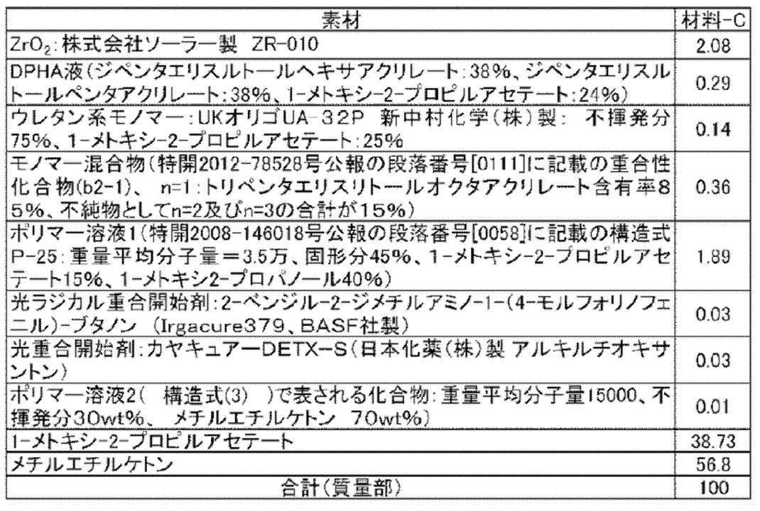
構造式(3)

なお、本明細書中の「wt%」は「質量%」と同義である。
Structural formula (3)
In the present specification, “wt%” is synonymous with “mass%”.
透明膜が製膜された透明フィルム基板を、真空チャンバー内に導入し、SnO2含有率
が10質量%のITOターゲット(インジウム:錫=95:5(モル比))を用いて、DCマグネトロンスパッタリング(条件:透明フィルム基板の温度150℃、アルゴン圧0.13Pa、酸素圧0.01Pa)により、厚み40nm、屈折率1.82のITO薄膜を形成し、透明フィルム基板上に透明膜と透明電極層を形成したフィルムを得た。ITO薄膜の表面抵抗は80Ω/□(Ω毎スクエア)であった。DCは直流(Direct Current)である。 -Formation of transparent electrode layer-
A transparent film substrate on which a transparent film is formed is introduced into a vacuum chamber, and DC magnetron sputtering is performed using an ITO target (indium: tin = 95: 5 (molar ratio)) with a SnO 2 content of 10% by mass. (Condition: Transparent film substrate temperature 150 ° C., argon pressure 0.13 Pa, oxygen pressure 0.01 Pa), an ITO thin film having a thickness of 40 nm and a refractive index of 1.82 was formed, and the transparent film and the transparent electrode were formed on the transparent film substrate. A layered film was obtained. The surface resistance of the ITO thin film was 80Ω / □ (Ω per square). DC is direct current.
厚み75μmのポリエチレンテレフタレートフィルム仮基材の上に、スリット状ノズルを用いて、下記の処方H1からなる熱可塑性樹脂層用塗布液を塗布し、乾燥させた。次に、下記の処方P1からなる中間層用塗布液を塗布し、乾燥させた。更に、下記の処方E1からなるエッチング用光硬化性樹脂層用塗布液を塗布し、乾燥させた。このようにして仮基材の上に乾燥厚みが15.1μmの熱可塑性樹脂層と、乾燥厚みが1.6μmの中間層と、厚み2.0μmエッチング用光硬化性樹脂層からなる積層体を得、最後に保護フィルム(厚み12μmポリプロピレンフィルム)を圧着した。こうして仮基材と熱可塑性樹脂層と中間層(酸素遮断膜)とエッチング用光硬化性樹脂層とが一体となった転写材料である、エッチング用感光性フィルムE1を作製した。 -Preparation of photosensitive film E1 for etching-
On a polyethylene terephthalate film temporary substrate having a thickness of 75 μm, a coating solution for a thermoplastic resin layer having the following formulation H1 was applied using a slit nozzle and dried. Next, an intermediate layer coating solution having the following formulation P1 was applied and dried. Further, a coating liquid for photocurable resin layer for etching comprising the following formulation E1 was applied and dried. In this way, a laminate comprising a thermoplastic resin layer having a dry thickness of 15.1 μm, an intermediate layer having a dry thickness of 1.6 μm, and a photocurable resin layer for etching having a thickness of 2.0 μm is formed on the temporary base material. Finally, a protective film (
・メチルメタクリレート/スチレン/メタクリル酸共重合体(共重合体組成(質量%):31/40/29、重量平均分子量60,000、酸価163mgKOH/g) ・・・16.0質量部
・モノマー1(商品名:BPE-500、新中村化学工業(株)製) ・・・5.6質量部
・ヘキサメチレンジイソシアネートのテトラエチレンオキシドモノメタクリレート0.5モル付加物 ・・・7.0質量部
・分子中に重合性基を1つ有する化合物としてのシクロヘキサンジメタノールモノアクリレート ・・・2.8質量部
・2-クロロ-N-ブチルアクリドン ・・・0.42質量部
・2,2-ビス(オルトクロロフェニル)-4,4’,5,5’-テトラフェニルビイミダゾール ・・・2.17質量部
・マラカイトグリーンシュウ酸塩 ・・・0.02質量部
・ロイコクリスタルバイオレット ・・・0.26質量部
・フェノチアジン ・・・0.013質量部
・界面活性剤(商品名:メガファックF-780F、大日本インキ(株)製) ・・・0.03質量部
・メチルエチルケトン ・・・40質量部
・1-メトキシ-2-プロパノール ・・・20質量部
なお、エッチング用光硬化性樹脂層用塗布液E1の溶剤除去後の100℃の粘度は2,500Pa・秒であった。 --- Photocurable resin layer coating solution for etching: Formula E1--
-Methyl methacrylate / styrene / methacrylic acid copolymer (copolymer composition (mass%): 31/40/29, weight average molecular weight 60,000, acid value 163 mg KOH / g) ... 16.0 parts by mass 1 (Brand name: BPE-500, manufactured by Shin-Nakamura Chemical Co., Ltd.) ... 5.6 parts by mass, 0.5-methylene tetraethylene oxide monomethacrylate adduct of hexamethylene diisocyanate ... 7.0 parts by mass Cyclohexanedimethanol monoacrylate as a compound having one polymerizable group in the molecule ... 2.8 parts by mass, 2-chloro-N-butylacridone ... 0.42 parts by mass, 2,2-bis (Orthochlorophenyl) -4,4 ′, 5,5′-tetraphenylbiimidazole ・ ・ ・ 2.17 parts by mass Malachite green oxalate ・ ・ ・ 0 02 parts by mass, leuco crystal violet ... 0.26 parts by mass, phenothiazine ... 0.013 parts by mass, surfactant (trade name: MegaFuck F-780F, manufactured by Dainippon Ink Co., Ltd.) ... 0.03 parts by mass · Methyl ethyl ketone ··· 40 parts by mass · 1-methoxy-2-propanol ... 20 parts by mass The viscosity at 100 ° C. after removal of the solvent of the coating liquid E1 for photocurable resin layer for etching is It was 2,500 Pa · sec.
・メタノール ・・・11.1質量部
・プロピレングリコールモノメチルエーテルアセテート ・・・6.36質量部
・メチルエチルケトン ・・・52.4質量部
・メチルメタクリレート/2-エチルヘキシルアクリレート/ベンジルメタクリレート/メタクリル酸共重合体(共重合組成比(モル比)=55/11.7/4.5/28.8、重量平均分子量=10万、Tg≒70℃) ・・・5.83質量部
・スチレン/アクリル酸共重合体(共重合組成比(モル比)=63/37、重量平均分子量=1万、Tg≒100℃) ・・・13.6質量部
・モノマー1(商品名:BPE-500、新中村化学工業(株)製) ・・・9.1質量部
・フッ素系ポリマー ・・・0.54質量部
上記のフッ素系ポリマーは、C6F13CH2CH2OCOCH=CH2 40部とH(OCH(CH3)CH2)7OCOCH=CH2 55部と、H(OCH2CH2)7OCOCH=CH2 5部との共重合体で、重量平均分子量3万、メチルエチルケトン30質量%溶液である(商品名:メガファックF780F、大日本インキ化学工業(株)製)。 --- Coating solution for thermoplastic resin layer: Formulation H1--
Methanol: 11.1 parts by mass Propylene glycol monomethyl ether acetate: 6.36 parts by mass Methyl ethyl ketone: 52.4 parts by mass Methyl methacrylate / 2-ethylhexyl acrylate / benzyl methacrylate / methacrylic acid copolymer Copolymer (copolymerization composition ratio (molar ratio) = 55 / 11.7 / 4.5 / 28.8, weight average molecular weight = 100,000, Tg≈70 ° C.) 5.83 mass parts styrene / acrylic acid Copolymer (copolymerization composition ratio (molar ratio) = 63/37, weight average molecular weight = 10,000, Tg≈100 ° C.) 13.6 parts by mass / monomer 1 (trade name: BPE-500, Shin-Nakamura chemical Co., Ltd.) ... 9.1 parts by mass fluorine-based polymer ... 0.54 parts by mass the above fluorine-containing polymer, C 6 F 13 CH 2 CH 2 OCOCH CH 2 40 parts of H (OCH (CH 3) CH 2) 7 and OCOCH = CH 2 55 parts of a copolymer of H (OCH 2 CH 2) 7 OCOCH =
・ポリビニルアルコール(商品名:PVA205、(株)クラレ製、鹸化度=88%、重合度550) ・・・32.2質量部
・ポリビニルピロリドン(商品名:K-30、アイエスピー・ジャパン(株)製) ・・・14.9質量部
・蒸留水 ・・・524質量部
・メタノール ・・・429質量部 --- Interlayer coating solution: Formulation P1--
Polyvinyl alcohol (trade name: PVA205, manufactured by Kuraray Co., Ltd., saponification degree = 88%, polymerization degree 550) 32.2 parts by mass Polyvinylpyrrolidone (trade name: K-30, IS Japan 14.9 parts by mass / distilled water 524 parts by mass / methanol 429 parts by mass
透明フィルム基板上に透明膜と透明電極層を形成したフィルムを洗浄し、保護フィルムを除去したエッチング用感光性フィルムE1を、透明電極層の表面とエッチング用光硬化性樹脂層の表面とが対向するようにラミネートした(透明フィルム基板の温度:130℃、ゴムローラー温度120℃、線圧100N/cm、搬送速度2.2m/分)。仮基材を剥離後、熱可塑性樹脂層と中間層はエッチング用光硬化性樹脂層とともに、透明電極層の表面に転写された。露光マスク(透明電極パターンを有する石英露光マスク)面と上記エッチング用光硬化性樹脂層との間の距離を200μmに設定し、熱可塑性樹脂層と中間層を介して、エッチング用光硬化性樹脂層を露光量50mJ/cm2(i線)でパターン露光した。
次に、トリエタノールアミン系現像液(トリエタノールアミン30質量%含有、商品名:T-PD2(富士フイルム(株)製)を純水で10倍に希釈した液)を用いて25℃で100秒間現像処理し、熱可塑性樹脂層と中間層を溶解し、界面活性剤含有洗浄液(商品名:T-SD3(富士フイルム(株)製)を純水で10倍に希釈した液)を用いて33℃で20秒間洗浄処理した。超高圧洗浄ノズルから純水を噴射し、回転ブラシで熱可塑性樹脂層上の残渣を除去し、更に130℃30分間のポストベーク処理を行って、透明フィルム基板上に透明膜と透明電極層とエッチング用光硬化性樹脂層パターンとを形成したフィルムを得た。
透明フィルム基板上に透明膜と透明電極層とエッチング用光硬化性樹脂層パターンとを形成したフィルムを、ITOエッチャント(塩酸、塩化カリウム水溶液。液温30℃)を入れたエッチング槽に浸漬し、100秒間処理した。このエッチング処理により、エッチング用光硬化性樹脂層で覆われていない露出した領域の透明電極層を溶解除去し、エッチング用光硬化性樹脂層パターンのついた透明電極パターン付のフィルムを得た。
次に、エッチング用光硬化性樹脂層パターンのついた透明電極パターン付のフィルムを、レジスト剥離液(N-メチル-2-ピロリドン、モノエタノールアミン、界面活性剤(商品名:サーフィノール465、エアープロダクツ(株)製、液温45℃)を入れたレジスト剥離槽に浸漬し、200秒間処理した。この剥離処理により、エッチング用光硬化性樹脂層を除去し、透明フィルム基板上に透明膜および透明電極パターンを形成した、透明電極パターンフィルムを得た。 -Formation of transparent electrode pattern-
A film having a transparent film and a transparent electrode layer formed on a transparent film substrate is washed, and the protective photosensitive film E1 is removed. The surface of the transparent electrode layer is opposite to the surface of the photocurable resin layer for etching. (Transparent film substrate temperature: 130 ° C., rubber roller temperature 120 ° C., linear pressure 100 N / cm, conveyance speed 2.2 m / min). After peeling off the temporary base material, the thermoplastic resin layer and the intermediate layer were transferred to the surface of the transparent electrode layer together with the photocurable resin layer for etching. The distance between the surface of the exposure mask (quartz exposure mask having a transparent electrode pattern) and the photocurable resin layer for etching is set to 200 μm, and the photocurable resin for etching is interposed through the thermoplastic resin layer and the intermediate layer. The layer was pattern-exposed with an exposure dose of 50 mJ / cm 2 (i-line).
Next, using a triethanolamine developer (containing 30% by mass of triethanolamine, trade name: T-PD2 (manufactured by FUJIFILM Corporation) diluted 10 times with pure water) at 25 ° C. for 100 times. Development is performed for 2 seconds, the thermoplastic resin layer and the intermediate layer are dissolved, and a surfactant-containing cleaning solution (trade name: T-SD3 (manufactured by Fuji Film Co., Ltd.) diluted 10 times with pure water) is used. Washing was performed at 33 ° C. for 20 seconds. Pure water is sprayed from an ultra-high pressure washing nozzle, the residue on the thermoplastic resin layer is removed with a rotating brush, and further post-baking treatment is performed at 130 ° C. for 30 minutes, and a transparent film and a transparent electrode layer are formed on the transparent film substrate. A film in which a photocurable resin layer pattern for etching was formed was obtained.
A film in which a transparent film, a transparent electrode layer, and a photocurable resin layer pattern for etching are formed on a transparent film substrate is immersed in an etching tank containing ITO etchant (hydrochloric acid, potassium chloride aqueous solution,
Next, a film with a transparent electrode pattern having a photocurable resin layer pattern for etching is applied to a resist stripping solution (N-methyl-2-pyrrolidone, monoethanolamine, a surfactant (trade name: Surfynol 465, air It was immersed in a resist stripping tank containing a product manufactured by Products Co., Ltd. (liquid temperature: 45 ° C.) and treated for 200 seconds, whereby the photocurable resin layer for etching was removed by this stripping treatment, and a transparent film and a transparent film on the transparent film substrate A transparent electrode pattern film in which a transparent electrode pattern was formed was obtained.
各実施例および比較例の転写フィルムから保護フィルムを剥離し、各実施例および比較例の静電容量型入力装置の電極保護膜を得た。 (Formation of electrode protection film for capacitive input device)
The protective film was peeled from the transfer film of each Example and Comparative Example, and the electrode protective film of the capacitance type input device of each Example and Comparative Example was obtained.
-転写-
保護フィルムを剥離した実施例1~18および各比較例の転写フィルム(静電容量型入力装置の電極保護膜)を用いて、透明フィルム基板上に透明膜および透明電極パターンを形成した透明電極パターンフィルムの透明膜と透明電極パターンを第二の樹脂層が覆うように、透明電極パターンフィルム上に各実施例および比較例の転写フィルムの第二の樹脂層、硬化性樹脂層および仮支持体をこの順で転写し、露光前の積層体を得た。転写は、透明フィルム基板の温度40℃、ゴムローラー温度110℃、線圧3N/cm、搬送速度2m/分で行った。
保護フィルムを剥離した実施例19の転写フィルムを用いた場合は、透明フィルム基板上に透明膜および透明電極パターンを形成した透明電極パターンフィルムの透明膜と透明電極パターンを硬化性樹脂層が覆うように、透明電極パターンフィルム上に実施例19の転写フィルムの硬化性樹脂層および仮支持体をこの順で転写し、露光前の積層体を得た。 (Production of laminate)
-Transcription-
A transparent electrode pattern in which a transparent film and a transparent electrode pattern are formed on a transparent film substrate using the transfer films of Examples 1 to 18 and the comparative examples (electrode protective film of a capacitive input device) with the protective film peeled off The second resin layer, the curable resin layer, and the temporary support of the transfer film of each Example and Comparative Example are placed on the transparent electrode pattern film so that the second resin layer covers the transparent film and the transparent electrode pattern of the film. Transfer was performed in this order to obtain a laminate before exposure. The transfer was performed at a transparent film substrate temperature of 40 ° C., a rubber roller temperature of 110 ° C., a linear pressure of 3 N / cm, and a conveyance speed of 2 m / min.
When the transfer film of Example 19 from which the protective film was peeled was used, the curable resin layer covered the transparent film and the transparent electrode pattern of the transparent electrode pattern film in which the transparent film and the transparent electrode pattern were formed on the transparent film substrate. Then, the curable resin layer of the transfer film of Example 19 and the temporary support were transferred in this order onto the transparent electrode pattern film to obtain a laminate before exposure.
得られた露光前の積層体に、超高圧水銀灯を有するプロキシミティー型露光機(日立ハイテク電子エンジニアリング(株)製)を用いて、露光マスク(オーバーコート形成用パターンを有す石英露光マスク)面と仮支持体との間の距離を125μmに設定し、仮支持体を介して露光量100mJ/cm2(i線)でパターン露光した。仮支持体を剥離後、パターン露光後の積層体(透明フィルム基板)を炭酸ソーダ2%水溶液32℃で60秒間洗浄処理した。洗浄処理後の透明フィルム基板に超高圧洗浄ノズルから超純水を噴射することで残渣を除去した。続いて、エアを吹きかけて透明フィルム基板上の水分を除去し、145℃、30分間のポストベーク処理を行った。実施例1~18および各比較例の転写フィルムを用いた場合は、透明フィルム基板上に、透明膜、透明電極パターン、透明電極パターンに直接接して配置された第二の樹脂層、および第二の樹脂層に直接接して配置された硬化性樹脂層をこの順で連続して有する実施例1~18および各比較例の積層体を得た。なお、透明電極パターンが存在しない領域では、第二の樹脂層は透明膜に直接接して配置されていた。
実施例19の転写フィルムを用いた場合は、透明フィルム基板上に、透明膜、透明電極パターン、透明電極パターンに直接接して配置された硬化性樹脂層をこの順で連続して有する実施例19の積層体を得た。
以上の工程より、本発明の転写フィルムはフォトリソグラフィ性を有することが確認された。 -Photolithography-
Using the proximity type exposure machine (manufactured by Hitachi High-Tech Electronics Engineering Co., Ltd.) having an ultra-high pressure mercury lamp, the exposure mask (quartz exposure mask with overcoat formation pattern) surface The distance between the substrate and the temporary support was set to 125 μm, and pattern exposure was performed through the temporary support with an exposure amount of 100 mJ / cm 2 (i-line). After peeling off the temporary support, the laminate (transparent film substrate) after pattern exposure was washed for 60 seconds at 32 ° C. with a 2% aqueous solution of sodium carbonate. Residues were removed by spraying ultrapure water from the ultra-high pressure cleaning nozzle onto the transparent film substrate after the cleaning treatment. Subsequently, air was blown to remove moisture on the transparent film substrate, and post-baking treatment was performed at 145 ° C. for 30 minutes. When the transfer films of Examples 1 to 18 and each comparative example were used, a transparent film, a transparent electrode pattern, a second resin layer disposed in direct contact with the transparent electrode pattern, and a second film on the transparent film substrate The laminates of Examples 1 to 18 and Comparative Examples each having a curable resin layer arranged in direct contact with the resin layer in this order were obtained. In the region where the transparent electrode pattern does not exist, the second resin layer was disposed in direct contact with the transparent film.
In the case where the transfer film of Example 19 was used, Example 19 having a transparent film, a transparent electrode pattern, and a curable resin layer disposed in direct contact with the transparent electrode pattern in this order on the transparent film substrate. A laminate was obtained.
From the above steps, it was confirmed that the transfer film of the present invention has photolithographic properties.
(透明電極パターンの隠蔽性)
各実施例および比較例の積層体と、黒色PET材とを、透明接着テープ(OCAテープ8171CL、3M(株)製)を介して、黒色PET材と硬化性樹脂層とが隣接するように接着させて、基板全体を遮光した評価用基板を作製した。
暗室において、蛍光灯(光源)と作製した評価用基板とを用いて、評価用基板の透明フィルム基板面側から光を入射させ、透明フィルム基板の光が入射する側の表面からの反射光を、斜めから目視観察した。
下記評価基準に基づいて透明電極パターンの隠蔽性を評価した。
-評価基準-
A:透明電極パターンが視認されない。
B:透明電極パターンが視認される。
得られた結果を下記表2に記載した。透明電極パターンの隠蔽性はAであることが好ましい。 <Evaluation of laminate>
(Concealment of transparent electrode pattern)
The laminated body of each Example and Comparative Example and the black PET material are bonded via a transparent adhesive tape (OCA tape 8171CL, manufactured by 3M) so that the black PET material and the curable resin layer are adjacent to each other. Thus, an evaluation substrate was produced in which the entire substrate was shielded from light.
In a dark room, using a fluorescent lamp (light source) and the produced evaluation substrate, light is incident from the transparent film substrate surface side of the evaluation substrate, and reflected light from the surface of the transparent film substrate on which light is incident is reflected. The sample was visually observed from an oblique direction.
Based on the following evaluation criteria, the concealability of the transparent electrode pattern was evaluated.
-Evaluation criteria-
A: A transparent electrode pattern is not visually recognized.
B: A transparent electrode pattern is visually recognized.
The obtained results are shown in Table 2 below. The concealability of the transparent electrode pattern is preferably A.

一方、保護フィルムの酸素透過係数が本発明で規定する下限値を下回る比較例1の転写フィルムは、気泡の発生が多かった。保護フィルムの表面粗さが本発明で規定する下限値を下回る比較例2の転写フィルムは、転写欠陥が多かった。保護フィルムの表面粗さが本発明で規定する上限値を上回る比較例3の転写フィルムは、気泡の発生が多かった。 From the obtained results, it was found that the transfer film of the present invention has photolithographic properties, generates less bubbles, and has few transfer defects.
On the other hand, the transfer film of Comparative Example 1 in which the oxygen permeation coefficient of the protective film was lower than the lower limit defined in the present invention had many bubbles. The transfer film of Comparative Example 2 in which the surface roughness of the protective film was lower than the lower limit specified in the present invention had many transfer defects. In the transfer film of Comparative Example 3 in which the surface roughness of the protective film exceeded the upper limit defined in the present invention, many bubbles were generated.
得られた積層体におけるn1、n2、T1およびT2は、反射分光膜厚計FE-3000(大塚電子(株)製)を用い、各実施例および比較例の転写フィルムにおけるn1、n2、T1およびT2の算出と同様の方法を1層ごとに繰り返して求めた。その概略を以下に示す。
(1)実施例および比較例の積層体について、各実施例および比較例で用いた透明フィルム基板、透明膜、透明電極パターンを順に積層したサンプル、ならびに透明フィルム基板、透明膜、透明電極パターンおよび第二の樹脂層を順に積層したサンプルなどについて、各層の屈折率と各層の厚みの見込み値をあらかじめ測定した。
(2)積層体中、透明フィルム基板/透明膜/透明電極パターン/第二の樹脂層/硬化性樹脂層の5層構成の部分を、縦横の辺の長さ5cm×5cmに切り出し、透明接着テープ(OCAテープ8171CL、3M(株)製)を介して、黒色PET材を接触させたサンプル片を作製した。透過型電子顕微鏡(TEM)を用いてサンプル片を構造解析し、各層の厚みの見込み値を求めた。サンプル片について、FE-3000(大塚電子(株)製)を用いて、直径40μmの測定スポットにて、0.2mm間隔で、任意の方向の直線上に100点の測定ポイントでの反射スペクトルを評価した。このとき、第二の樹脂層と透明電極パターンの界面および、硬化性樹脂層と第二の樹脂層の界面を考慮するため、第二の樹脂層、透明フィルム基板、透明膜および透明電極パターンの屈折率および硬化性樹脂層の厚みの平均値の見込み値、ならびに、第二の樹脂層の厚みの平均値の見込み値を計算式に代入した状態で、透明フィルム基板/透明膜/透明電極パターン/第二の樹脂層/硬化性樹脂層の5層構成の部分の反射スペクトルから硬化性樹脂層の屈折率n1と第二の樹脂層の屈折率n2と100点の測定ポイントにおける硬化性樹脂層および第二の樹脂層の厚みをシミュレーション計算により、フィッティングして求めた。さらに硬化性樹脂層および第二の樹脂層の厚みの平均値、最大値、最小値および標準偏差を算出して、n1、n2、T1およびT2を算出した。本明細書中では、任意の方向をサンプル片の一辺と平行な方向とし、100点の測定ポイント(すなわち2cm長)をサンプル片の一辺の中心から均等に1cmずつの範囲とした。 N 1, n 2, T 1 and T 2 in the laminate of the Examples and Comparative Examples were respectively n 1, n 2, T 1 and T 2 coincide in the transfer films of Examples and Comparative Examples.
N 1 , n 2 , T 1, and T 2 in the obtained laminate were measured by using a reflection spectral film thickness meter FE-3000 (manufactured by Otsuka Electronics Co., Ltd.), and n 1 in the transfer films of each Example and Comparative Example. , N 2 , T 1 and T 2 were obtained by repeating the same method for each layer. The outline is shown below.
(1) About the laminated body of an Example and a comparative example, the transparent film substrate used by each Example and the comparative example, the transparent film, the sample which laminated | stacked the transparent electrode pattern in order, and a transparent film substrate, a transparent film, a transparent electrode pattern, and About the sample etc. which laminated | stacked the 2nd resin layer in order, the expected value of the refractive index of each layer and the thickness of each layer was measured previously.
(2) In the laminate, a portion having a five-layer configuration of transparent film substrate / transparent film / transparent electrode pattern / second resin layer / curable resin layer is cut into a length and width of 5 cm × 5 cm and transparently bonded. The sample piece which contacted the black PET material was produced through the tape (OCA tape 8171CL, 3M Co., Ltd. product). The sample piece was subjected to structural analysis using a transmission electron microscope (TEM), and the expected value of the thickness of each layer was determined. Using the FE-3000 (manufactured by Otsuka Electronics Co., Ltd.), the sample spectrum was measured at 100 measurement points on a straight line in an arbitrary direction at 0.2 mm intervals at a measurement spot with a diameter of 40 μm. evaluated. At this time, in order to consider the interface between the second resin layer and the transparent electrode pattern and the interface between the curable resin layer and the second resin layer, the second resin layer, the transparent film substrate, the transparent film, and the transparent electrode pattern Transparent film substrate / transparent film / transparent electrode pattern with the expected value of the average value of the refractive index and the thickness of the curable resin layer and the expected value of the average value of the thickness of the second resin layer substituted in the calculation formula curable in / the second resin layer / cured
積層体の断面を切削した後、TEM(透過型電子顕微鏡)で、断面を観察する。積層体の硬化性樹脂層または第二の樹脂層の膜断面積における、金属酸化物粒子の占有面積の割合を層内の任意の3箇所で測定し、その平均値を体積分率(VR)と見なす。
体積分率(VR)と重量分率(WR)は、下記の式で換算することにより、積層体の硬化性樹脂層または第二の樹脂層内における金属酸化物粒子の重量分率(WR)を算出する。
WR=D*VR/(1.1*(1-VR)+D*VR)
D:金属酸化物粒子の比重
金属酸化物粒子が、酸化チタンの場合D=4.0、酸化ジルコニウムの場合D=6.0として計算することができる。
なお、各実施例および比較例の積層体の硬化性樹脂層または第二の樹脂層の金属酸化物粒子の含有量は、硬化性樹脂層または第二の樹脂層の組成から算出することもできる。 Furthermore, when the content of the metal oxide particles in the curable resin layer and the second resin layer of the laminates of each Example and Comparative Example was measured by the following method, the values described in Table 2 were obtained.
After cutting the cross section of the laminate, the cross section is observed with a TEM (transmission electron microscope). The proportion of the area occupied by the metal oxide particles in the film cross-sectional area of the curable resin layer or the second resin layer of the laminate is measured at any three locations in the layer, and the average value is the volume fraction (VR). Is considered.
The volume fraction (VR) and the weight fraction (WR) are converted by the following formula to obtain the weight fraction (WR) of the metal oxide particles in the curable resin layer or the second resin layer of the laminate. Is calculated.
WR = D * VR / (1.1 * (1-VR) + D * VR)
D: Specific gravity of metal oxide particles The metal oxide particles can be calculated as D = 4.0 when titanium oxide is used, and D = 6.0 when zirconium oxide is used.
In addition, the content of the metal oxide particles in the curable resin layer or the second resin layer of the laminates of the examples and comparative examples can also be calculated from the composition of the curable resin layer or the second resin layer. .
2 マスク層
3 第一の透明電極パターン
3a パッド部分
3b 接続部分
4 透明電極パターン(第二の透明電極パターン)
5 絶縁層
6 別の導電性要素
7 硬化性樹脂層
8 開口部
10 静電容量型入力装置
11 透明膜
12 第二の樹脂層
13 積層体
21 透明電極パターンと第二の樹脂層と硬化性樹脂層がこの順に積層された領域
22 非パターン領域
α テーパー角
26 仮支持体
29 保護フィルム
30 転写フィルム
31 引き回し配線の端末部
33 硬化性樹脂層と第二の樹脂層の硬化部
34 引き回し配線の末端部に対応する開口部(硬化性樹脂層と第二の樹脂層の未硬化部)
C 第一の方向
D 第二の方向
DESCRIPTION OF
5 Insulating
C First direction D Second direction
Claims (15)
- 仮支持体と、
硬化性樹脂層と、
保護フィルムと、
をこの順で有する転写フィルムであって、
前記保護フィルムの酸素透過係数が100cm3・25μm/m2・24時間・atm以上であり、
前記保護フィルムの前記硬化性樹脂層側の表面粗さRaが5~60nmである、転写フィルム。 A temporary support;
A curable resin layer;
A protective film;
In this order,
The oxygen permeability coefficient of the protective film is 100 cm 3 · 25 μm / m 2 · 24 hours · atm or more,
A transfer film having a surface roughness Ra of 5 to 60 nm on the side of the curable resin layer of the protective film. - 前記保護フィルムの酸素透過係数が5000cm3・25μm/m2・24時間・atm以下である、請求項1に記載の転写フィルム。 The transfer film according to claim 1, wherein the protective film has an oxygen permeability coefficient of 5000 cm 3 · 25 μm / m 2 · 24 hours · atm or less.
- 前記保護フィルムの厚みが10~75μmである、請求項1または2に記載の転写フィルム。 The transfer film according to claim 1 or 2, wherein the protective film has a thickness of 10 to 75 µm.
- 前記保護フィルムがポリエチレンテレフタレートまたはポリプロピレンを含む、請求項1~3のいずれか一項に記載の転写フィルム。 The transfer film according to any one of claims 1 to 3, wherein the protective film contains polyethylene terephthalate or polypropylene.
- 前記保護フィルムと前記硬化性樹脂層の間に第二の樹脂層を有し、
前記第二の樹脂層が屈折率1.50以上の粒子を前記第二の樹脂層の全固形分に対して60~90質量%含有する、請求項1~4のいずれか一項に記載の転写フィルム。 Having a second resin layer between the protective film and the curable resin layer;
The second resin layer according to any one of claims 1 to 4, wherein the second resin layer contains particles having a refractive index of 1.50 or more in an amount of 60 to 90% by mass with respect to the total solid content of the second resin layer. Transfer film. - 前記硬化性樹脂層の屈折率n1と前記第二の樹脂層の屈折率n2とが下記式1を満たす、請求項5に記載の転写フィルム。
式1: n1<n2 Transfer film of which the refractive index n 1 of the curable resin layer and the refractive index n 2 of the second resin layer satisfies the following formula 1, according to claim 5.
Formula 1: n 1 <n 2 - 前記第二の樹脂層が、硬化性である、請求項5または6のいずれか一項に記載の転写フィルム。 The transfer film according to any one of claims 5 and 6, wherein the second resin layer is curable.
- 前記屈折率1.50以上の粒子が酸化ジルコニウム粒子または酸化チタン粒子である、請求項5~7のいずれか一項に記載の転写フィルム。 The transfer film according to any one of claims 5 to 7, wherein the particles having a refractive index of 1.50 or more are zirconium oxide particles or titanium oxide particles.
- 前記硬化性樹脂層および前記第二の樹脂層が直接接する、請求項5~8のいずれか一項に記載の転写フィルム。 The transfer film according to any one of claims 5 to 8, wherein the curable resin layer and the second resin layer are in direct contact with each other.
- 前記硬化性樹脂層および前記第二の樹脂層がアルカリ可溶性である、請求項5~9のいずれか一項に記載の転写フィルム。 The transfer film according to any one of claims 5 to 9, wherein the curable resin layer and the second resin layer are alkali-soluble.
- 前記硬化性樹脂層が、重合性化合物およびバインダーポリマーを含み、
前記バインダーポリマーがアルカリ可溶性樹脂である、請求項1~10のいずれか一項に記載の転写フィルム。 The curable resin layer contains a polymerizable compound and a binder polymer,
The transfer film according to any one of claims 1 to 10, wherein the binder polymer is an alkali-soluble resin. - ロール形状である、請求項1~11のいずれか一項に記載の転写フィルム。 The transfer film according to any one of claims 1 to 11, which has a roll shape.
- 請求項1~12のいずれか一項に記載の転写フィルムから、前記保護フィルムが取り除かれた、静電容量型入力装置の電極保護膜。 An electrode protective film for a capacitive input device, wherein the protective film is removed from the transfer film according to any one of claims 1 to 12.
- 静電容量型入力装置の電極を含む基板と、
請求項13に記載の静電容量型入力装置の電極保護膜とを有する、積層体。 A substrate including an electrode of a capacitive input device;
A laminate comprising the electrode protective film of the capacitive input device according to claim 13. - 請求項13に記載の静電容量型入力装置の電極保護膜または請求項14に記載の積層体を有する、静電容量型入力装置。
A capacitance-type input device comprising the electrode protective film of the capacitance-type input device according to claim 13 or the laminate according to claim 14.
Priority Applications (2)
| Application Number | Priority Date | Filing Date | Title |
|---|---|---|---|
| KR1020187022694A KR102078112B1 (en) | 2016-03-30 | 2017-02-17 | Transfer film, electrode protective film of capacitive input device, laminate and capacitive input device |
| CN201780012670.7A CN108698370B (en) | 2016-03-30 | 2017-02-17 | Transfer film, electrode protection film for capacitive input device, laminate, and capacitive input device |
Applications Claiming Priority (2)
| Application Number | Priority Date | Filing Date | Title |
|---|---|---|---|
| JP2016068376A JP6584357B2 (en) | 2016-03-30 | 2016-03-30 | Transfer film, electrode protection film of capacitive input device, laminate, and capacitive input device |
| JP2016-068376 | 2016-03-30 |
Publications (1)
| Publication Number | Publication Date |
|---|---|
| WO2017169257A1 true WO2017169257A1 (en) | 2017-10-05 |
Family
ID=59963053
Family Applications (1)
| Application Number | Title | Priority Date | Filing Date |
|---|---|---|---|
| PCT/JP2017/005833 WO2017169257A1 (en) | 2016-03-30 | 2017-02-17 | Transfer film, electrode protection film of capacitive input device, laminate, and capacitive input device |
Country Status (4)
| Country | Link |
|---|---|
| JP (1) | JP6584357B2 (en) |
| KR (1) | KR102078112B1 (en) |
| CN (1) | CN108698370B (en) |
| WO (1) | WO2017169257A1 (en) |
Cited By (1)
| Publication number | Priority date | Publication date | Assignee | Title |
|---|---|---|---|---|
| WO2022215427A1 (en) * | 2021-04-06 | 2022-10-13 | コニカミノルタ株式会社 | Stretched film, method for producing stretched film, polarizing plate and liquid crystal display device |
Families Citing this family (6)
| Publication number | Priority date | Publication date | Assignee | Title |
|---|---|---|---|---|
| US20210004101A1 (en) * | 2017-11-24 | 2021-01-07 | Huawei Technologies Co., Ltd. | Touch Display Panel, Flexible Display Apparatus, and Method for Manufacturing Touch Display Panel |
| JP6989711B2 (en) * | 2018-10-18 | 2022-01-05 | 富士フイルム株式会社 | A transfer film, a cured film manufacturing method, a laminated body manufacturing method, and a touch panel manufacturing method. |
| JP6687794B2 (en) * | 2019-09-02 | 2020-04-28 | 富士フイルム株式会社 | Transfer film, electrode protective film of electrostatic capacitance type input device, laminated body and electrostatic capacitance type input device |
| JP7417639B2 (en) * | 2020-01-29 | 2024-01-18 | 富士フイルム株式会社 | Sensor film, touch sensor, image display device |
| CN115335222B (en) * | 2020-03-26 | 2024-01-16 | 东洋纺株式会社 | Laminate for transferring thin film layer |
| JPWO2022054374A1 (en) * | 2020-09-14 | 2022-03-17 |
Citations (7)
| Publication number | Priority date | Publication date | Assignee | Title |
|---|---|---|---|---|
| JP5257648B2 (en) * | 2007-11-27 | 2013-08-07 | 日立化成株式会社 | Photosensitive element and method for producing the same |
| JP2014010814A (en) * | 2012-07-03 | 2014-01-20 | Fujifilm Corp | Transparent laminate, capacitance type input device and image display device |
| JP2014108541A (en) * | 2012-11-30 | 2014-06-12 | Fujifilm Corp | Transfer film and transparent laminate, method for manufacturing the same, electrostatic capacitive input device and image display device |
| WO2015141766A1 (en) * | 2014-03-20 | 2015-09-24 | 富士フイルム株式会社 | Photosensitive laminate, transfer material, patterned photosensitive laminate, method for producing same, touch panel, and image display device |
| WO2015156292A1 (en) * | 2014-04-10 | 2015-10-15 | 日立化成株式会社 | Photosensitive resin composition, photosensitive element, and method for manufacturing processed glass substrate |
| WO2015177947A1 (en) * | 2014-05-23 | 2015-11-26 | 日立化成株式会社 | Method for forming resist pattern, method for manufacturing printed wiring board, photosensitive resin composition for projection exposure and photosensitive element |
| JP2016030791A (en) * | 2014-07-29 | 2016-03-07 | 信越化学工業株式会社 | Silicone structure-bearing polymer, negative resist material, photo-curable dry film, patterning process, and electric/electronic part-protecting film |
Family Cites Families (4)
| Publication number | Priority date | Publication date | Assignee | Title |
|---|---|---|---|---|
| JP4888589B2 (en) | 2008-03-25 | 2012-02-29 | ソニー株式会社 | Capacitance type input device, display device with input function, and electronic device |
| JP2010086684A (en) | 2008-09-30 | 2010-04-15 | Kuramoto Seisakusho Co Ltd | Optical thin film with transparent conductive wiring film |
| JP5213694B2 (en) | 2008-12-26 | 2013-06-19 | Smk株式会社 | Transparent panel and touch panel |
| JP2012078528A (en) | 2010-09-30 | 2012-04-19 | Fujifilm Corp | Photosensitive composition, photosensitive resin transfer film, resin pattern and production method of resin pattern, substrate for liquid crystal display device, and liquid crystal display device |
-
2016
- 2016-03-30 JP JP2016068376A patent/JP6584357B2/en active Active
-
2017
- 2017-02-17 KR KR1020187022694A patent/KR102078112B1/en active IP Right Grant
- 2017-02-17 CN CN201780012670.7A patent/CN108698370B/en active Active
- 2017-02-17 WO PCT/JP2017/005833 patent/WO2017169257A1/en active Application Filing
Patent Citations (7)
| Publication number | Priority date | Publication date | Assignee | Title |
|---|---|---|---|---|
| JP5257648B2 (en) * | 2007-11-27 | 2013-08-07 | 日立化成株式会社 | Photosensitive element and method for producing the same |
| JP2014010814A (en) * | 2012-07-03 | 2014-01-20 | Fujifilm Corp | Transparent laminate, capacitance type input device and image display device |
| JP2014108541A (en) * | 2012-11-30 | 2014-06-12 | Fujifilm Corp | Transfer film and transparent laminate, method for manufacturing the same, electrostatic capacitive input device and image display device |
| WO2015141766A1 (en) * | 2014-03-20 | 2015-09-24 | 富士フイルム株式会社 | Photosensitive laminate, transfer material, patterned photosensitive laminate, method for producing same, touch panel, and image display device |
| WO2015156292A1 (en) * | 2014-04-10 | 2015-10-15 | 日立化成株式会社 | Photosensitive resin composition, photosensitive element, and method for manufacturing processed glass substrate |
| WO2015177947A1 (en) * | 2014-05-23 | 2015-11-26 | 日立化成株式会社 | Method for forming resist pattern, method for manufacturing printed wiring board, photosensitive resin composition for projection exposure and photosensitive element |
| JP2016030791A (en) * | 2014-07-29 | 2016-03-07 | 信越化学工業株式会社 | Silicone structure-bearing polymer, negative resist material, photo-curable dry film, patterning process, and electric/electronic part-protecting film |
Cited By (1)
| Publication number | Priority date | Publication date | Assignee | Title |
|---|---|---|---|---|
| WO2022215427A1 (en) * | 2021-04-06 | 2022-10-13 | コニカミノルタ株式会社 | Stretched film, method for producing stretched film, polarizing plate and liquid crystal display device |
Also Published As
| Publication number | Publication date |
|---|---|
| JP2017177546A (en) | 2017-10-05 |
| KR102078112B1 (en) | 2020-02-17 |
| KR20180101465A (en) | 2018-09-12 |
| CN108698370B (en) | 2020-07-17 |
| JP6584357B2 (en) | 2019-10-02 |
| CN108698370A (en) | 2018-10-23 |
Similar Documents
| Publication | Publication Date | Title |
|---|---|---|
| JP6584357B2 (en) | Transfer film, electrode protection film of capacitive input device, laminate, and capacitive input device | |
| US10649331B2 (en) | Composition for forming touch panel electrode protective film, transfer film, laminate, protective film for touch panel electrode and method for forming same, capacitive input device, and image display device | |
| JP6284891B2 (en) | Composition for forming touch panel electrode protective film, transfer film, transparent laminate, protective film for touch panel electrode and method for forming the same, capacitive input device, and image display device | |
| JP6307036B2 (en) | Transfer film, protective film for electrode of capacitive input device, laminate, method for producing laminate, and capacitive input device | |
| WO2017038278A1 (en) | Transfer film, electrode protection film for capacitance-type input device, laminated body, method for manufacturing laminated body, and capacitance-type input device | |
| JP6566982B2 (en) | Transfer film, electrode protective film, laminate, capacitance-type input device, and transfer film manufacturing method | |
| WO2017018406A1 (en) | Composite equipped with transparent electrode, transfer film, method for manufacturing composite equipped with transparent electrode, and capacitive input device | |
| JP6615901B2 (en) | TRANSFER FILM, ELECTRODE PROTECTIVE FILM FOR CAPACITANCE TYPE INPUT DEVICE, LAMINATE, METHOD FOR PRODUCING LAMINATE, AND CAPACITANCE INPUT DEVICE | |
| WO2016143892A1 (en) | Transfer film, transparent laminate, capacitive input device and image display device | |
| WO2016009980A1 (en) | Method for producing multilayer material, multilayer material, method for producing transparent laminate, transparent laminate, capacitive input device and image display device | |
| WO2016159043A1 (en) | Transfer film, laminate, capacitance-type input device, and image display device | |
| KR102521385B1 (en) | Transfer film, electrode protective film of capacitance type input device, laminate and capacitance type input device | |
| JP6587769B1 (en) | Transfer film, electrode protection film of capacitive input device, laminate, and capacitive input device | |
| JP6687794B2 (en) | Transfer film, electrode protective film of electrostatic capacitance type input device, laminated body and electrostatic capacitance type input device | |
| JP6888148B2 (en) | Transfer film, electrode protective film for capacitive input device, laminate and capacitive input device | |
| JP6474713B2 (en) | Transfer material, transfer material manufacturing method, touch panel manufacturing method, and touch panel | |
| JP6431832B2 (en) | Transfer material, roll, touch panel manufacturing method, and touch panel |
Legal Events
| Date | Code | Title | Description |
|---|---|---|---|
| ENP | Entry into the national phase |
Ref document number: 20187022694 Country of ref document: KR Kind code of ref document: A |
|
| WWE | Wipo information: entry into national phase |
Ref document number: 1020187022694 Country of ref document: KR |
|
| NENP | Non-entry into the national phase |
Ref country code: DE |
|
| 121 | Ep: the epo has been informed by wipo that ep was designated in this application |
Ref document number: 17773805 Country of ref document: EP Kind code of ref document: A1 |
|
| 122 | Ep: pct application non-entry in european phase |
Ref document number: 17773805 Country of ref document: EP Kind code of ref document: A1 |