WO2017169204A1 - 水素製造システム - Google Patents
水素製造システム Download PDFInfo
- Publication number
- WO2017169204A1 WO2017169204A1 PCT/JP2017/005272 JP2017005272W WO2017169204A1 WO 2017169204 A1 WO2017169204 A1 WO 2017169204A1 JP 2017005272 W JP2017005272 W JP 2017005272W WO 2017169204 A1 WO2017169204 A1 WO 2017169204A1
- Authority
- WO
- WIPO (PCT)
- Prior art keywords
- power
- gas
- hydrogen
- cell
- production system
- Prior art date
- Legal status (The legal status is an assumption and is not a legal conclusion. Google has not performed a legal analysis and makes no representation as to the accuracy of the status listed.)
- Ceased
Links
Images


Classifications
-
- C—CHEMISTRY; METALLURGY
- C25—ELECTROLYTIC OR ELECTROPHORETIC PROCESSES; APPARATUS THEREFOR
- C25B—ELECTROLYTIC OR ELECTROPHORETIC PROCESSES FOR THE PRODUCTION OF COMPOUNDS OR NON-METALS; APPARATUS THEREFOR
- C25B1/00—Electrolytic production of inorganic compounds or non-metals
- C25B1/01—Products
- C25B1/02—Hydrogen or oxygen
- C25B1/04—Hydrogen or oxygen by electrolysis of water
-
- C—CHEMISTRY; METALLURGY
- C25—ELECTROLYTIC OR ELECTROPHORETIC PROCESSES; APPARATUS THEREFOR
- C25B—ELECTROLYTIC OR ELECTROPHORETIC PROCESSES FOR THE PRODUCTION OF COMPOUNDS OR NON-METALS; APPARATUS THEREFOR
- C25B15/00—Operating or servicing cells
- C25B15/02—Process control or regulation
- C25B15/021—Process control or regulation of heating or cooling
-
- C—CHEMISTRY; METALLURGY
- C25—ELECTROLYTIC OR ELECTROPHORETIC PROCESSES; APPARATUS THEREFOR
- C25B—ELECTROLYTIC OR ELECTROPHORETIC PROCESSES FOR THE PRODUCTION OF COMPOUNDS OR NON-METALS; APPARATUS THEREFOR
- C25B15/00—Operating or servicing cells
- C25B15/02—Process control or regulation
- C25B15/023—Measuring, analysing or testing during electrolytic production
-
- C—CHEMISTRY; METALLURGY
- C25—ELECTROLYTIC OR ELECTROPHORETIC PROCESSES; APPARATUS THEREFOR
- C25B—ELECTROLYTIC OR ELECTROPHORETIC PROCESSES FOR THE PRODUCTION OF COMPOUNDS OR NON-METALS; APPARATUS THEREFOR
- C25B15/00—Operating or servicing cells
- C25B15/02—Process control or regulation
- C25B15/023—Measuring, analysing or testing during electrolytic production
- C25B15/025—Measuring, analysing or testing during electrolytic production of electrolyte parameters
-
- C—CHEMISTRY; METALLURGY
- C25—ELECTROLYTIC OR ELECTROPHORETIC PROCESSES; APPARATUS THEREFOR
- C25B—ELECTROLYTIC OR ELECTROPHORETIC PROCESSES FOR THE PRODUCTION OF COMPOUNDS OR NON-METALS; APPARATUS THEREFOR
- C25B15/00—Operating or servicing cells
- C25B15/02—Process control or regulation
- C25B15/023—Measuring, analysing or testing during electrolytic production
- C25B15/025—Measuring, analysing or testing during electrolytic production of electrolyte parameters
- C25B15/029—Concentration
-
- C—CHEMISTRY; METALLURGY
- C25—ELECTROLYTIC OR ELECTROPHORETIC PROCESSES; APPARATUS THEREFOR
- C25B—ELECTROLYTIC OR ELECTROPHORETIC PROCESSES FOR THE PRODUCTION OF COMPOUNDS OR NON-METALS; APPARATUS THEREFOR
- C25B15/00—Operating or servicing cells
- C25B15/02—Process control or regulation
- C25B15/023—Measuring, analysing or testing during electrolytic production
- C25B15/025—Measuring, analysing or testing during electrolytic production of electrolyte parameters
- C25B15/033—Conductivity
-
- C—CHEMISTRY; METALLURGY
- C25—ELECTROLYTIC OR ELECTROPHORETIC PROCESSES; APPARATUS THEREFOR
- C25B—ELECTROLYTIC OR ELECTROPHORETIC PROCESSES FOR THE PRODUCTION OF COMPOUNDS OR NON-METALS; APPARATUS THEREFOR
- C25B9/00—Cells or assemblies of cells; Constructional parts of cells; Assemblies of constructional parts, e.g. electrode-diaphragm assemblies; Process-related cell features
- C25B9/60—Constructional parts of cells
- C25B9/65—Means for supplying current; Electrode connections; Electric inter-cell connections
-
- C—CHEMISTRY; METALLURGY
- C25—ELECTROLYTIC OR ELECTROPHORETIC PROCESSES; APPARATUS THEREFOR
- C25B—ELECTROLYTIC OR ELECTROPHORETIC PROCESSES FOR THE PRODUCTION OF COMPOUNDS OR NON-METALS; APPARATUS THEREFOR
- C25B9/00—Cells or assemblies of cells; Constructional parts of cells; Assemblies of constructional parts, e.g. electrode-diaphragm assemblies; Process-related cell features
- C25B9/70—Assemblies comprising two or more cells
- C25B9/73—Assemblies comprising two or more cells of the filter-press type
- C25B9/75—Assemblies comprising two or more cells of the filter-press type having bipolar electrodes
-
- C—CHEMISTRY; METALLURGY
- C25—ELECTROLYTIC OR ELECTROPHORETIC PROCESSES; APPARATUS THEREFOR
- C25B—ELECTROLYTIC OR ELECTROPHORETIC PROCESSES FOR THE PRODUCTION OF COMPOUNDS OR NON-METALS; APPARATUS THEREFOR
- C25B9/00—Cells or assemblies of cells; Constructional parts of cells; Assemblies of constructional parts, e.g. electrode-diaphragm assemblies; Process-related cell features
- C25B9/70—Assemblies comprising two or more cells
- C25B9/73—Assemblies comprising two or more cells of the filter-press type
- C25B9/77—Assemblies comprising two or more cells of the filter-press type having diaphragms
-
- Y—GENERAL TAGGING OF NEW TECHNOLOGICAL DEVELOPMENTS; GENERAL TAGGING OF CROSS-SECTIONAL TECHNOLOGIES SPANNING OVER SEVERAL SECTIONS OF THE IPC; TECHNICAL SUBJECTS COVERED BY FORMER USPC CROSS-REFERENCE ART COLLECTIONS [XRACs] AND DIGESTS
- Y02—TECHNOLOGIES OR APPLICATIONS FOR MITIGATION OR ADAPTATION AGAINST CLIMATE CHANGE
- Y02E—REDUCTION OF GREENHOUSE GAS [GHG] EMISSIONS, RELATED TO ENERGY GENERATION, TRANSMISSION OR DISTRIBUTION
- Y02E60/00—Enabling technologies; Technologies with a potential or indirect contribution to GHG emissions mitigation
- Y02E60/30—Hydrogen technology
- Y02E60/36—Hydrogen production from non-carbon containing sources, e.g. by water electrolysis
Definitions
- Embodiment relates to a hydrogen production system.
- renewable energy refers to energy that is permanently supplemented by the natural world, such as wind and sunlight.
- Power generation facilities that use renewable energy for example, wind power generators installed in mountainous areas, solar cell panels installed in the desert, etc., install hydrogen production equipment, and power supplied from these power generation facilities Is used to produce hydrogen by electrolyzing water, transport the produced hydrogen to the consumption area, and supply it to fuel cells and fuel cell vehicles.
- the output power of a wind power generator depends on wind
- the output power of a solar cell panel depends on sunlight. If the output power is unstable, the hydrogen production system may not operate well, and it may be difficult to stably produce hydrogen gas with higher purity.
- An object of the embodiment is to provide a hydrogen production system capable of stably producing hydrogen gas with higher purity even when supplied power is unstable.
- the hydrogen production system is an electrolysis that includes a rectifier that is supplied with first power from the outside and outputs DC second power, and a plurality of cells that are supplied with the second power to electrolyze an alkaline aqueous solution.
- a tank a buffer tank connected to the cathode side of the plurality of cells, a compressor connected to the buffer tank for compressing gas, and whether to supply the second power to each of the plurality of cells.
- a control device to be selected.
- 1 is a block diagram showing a hydrogen production system according to a first embodiment. It is a block diagram which shows the rectifier of 1st Embodiment. It is a block diagram which shows the alkaline water electrolysis apparatus of 1st Embodiment. It is sectional drawing which shows the cell of 1st Embodiment. It is a figure which shows the hydrogen production system which concerns on 1st Embodiment. 1 is a perspective view showing a hydrogen production system according to a first embodiment. (A) to (c) are graphs showing time variation of each power, with time on the horizontal axis and power on the vertical axis. It is a figure which shows the hydrogen production system which concerns on 2nd Embodiment.
- the hydrogen production system according to the present embodiment is a system for producing hydrogen gas by electrolyzing water by an alkaline electrolysis method.
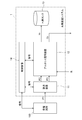
- FIG. 1 is a block diagram showing a hydrogen production system according to this embodiment.
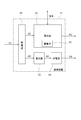
- FIG. 2 is a block diagram showing the rectifier of this embodiment.
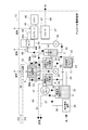
- FIG. 3 is a block diagram showing the alkaline water electrolysis apparatus of the present embodiment.
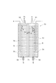
- FIG. 4 is a cross-sectional view showing the cell of this embodiment.
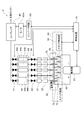
- FIG. 5 is a diagram showing a hydrogen production system according to the present embodiment.
- FIG. 6 is a perspective view showing a hydrogen production system according to the present embodiment.
- the flow of current and signal is indicated by a two-dot chain line
- the flow of gas is indicated by a one-dot chain line
- the flow of liquid is indicated by a solid line.
- FIG. 5 shows only components directly related to the cell selection operation.
- FIG. 6 shows only relatively large components, and small components and piping are not shown.
- the hydrogen production system 1 is installed near a power generation facility 100.
- the power generation facility 100 is a power generation facility using renewable energy, for example, a wind power generation facility or a solar power generation facility.
- the power generation facility 100 is installed in a remote area, and thus the hydrogen production system 1 is also installed in a remote area.
- “land” refers to land that is not connected to an existing power system.
- the remote area is a land far away from a city such as a mountainous area or a remote island.
- the power generation facility 100 outputs the AC power P1 in an unstable manner.
- a rectifying device 11 In the hydrogen production system 1, a rectifying device 11, an alkaline water electrolysis device 12, a hydrogen tank 13, and a control device 14 are provided.
- the rectifier 11 is supplied with AC power P1 from the power generation facility 100 and outputs DC power P2 and AC power P3.
- the alkaline water electrolysis apparatus 12 is supplied with DC power P2 and AC power P3 from the rectifier 11 and supplied with water from the outside to produce hydrogen. Oxygen produced with hydrogen is exhausted to the outside.
- the water supplied to the alkaline water electrolyzer 12 is, for example, tap water when a water supply is provided, or ground water or water carried from the outside when a water supply is not provided.
- these tap water, groundwater, and water brought in from the outside are collectively referred to as “general water”.
- the hydrogen tank 13 stores hydrogen produced by the alkaline water electrolysis device 12.
- the control device 14 exchanges signals between the rectifying device 11 and the alkaline water electrolysis device 12 to control the rectifying device 11 and the alkaline water electrolysis device 12.
- the control device 14 may exchange signals with the power generation facility 100 or may control the power generation facility 100.
- the rectifier 11 is provided with a power receiving panel 21, a rectifier 22, a transformer 23, and a distribution board 24.
- the power receiving panel 21 is supplied with AC power P ⁇ b> 1 from the power generation facility 100 (see FIG. 1), and distributes the power to the rectifier 22 and the transformer 23.
- the rectifier 22 converts the supplied AC power into DC power P2 and outputs it.
- a storage battery 25 is provided in the rectifier 22 and can store DC power P2.
- the storage battery 25 can be constituted by, for example, a lithium ion storage system IPCS-LIB-S250 manufactured by Toshiba.
- the transformer 23 adjusts the voltage of the AC power supplied from the power receiving panel 21 and outputs it to the distribution board 24.
- the distribution board 24 converts the AC power supplied from the transformer 23 into AC power P3 having a predetermined standard voltage and outputs it.
- the voltage of the AC power P3 is, for example, 200V.
- the alkaline water electrolysis apparatus 12 is provided with an electrolytic cell 32, a cathode gas gas / liquid separation chamber 33, an anode gas gas / liquid separation chamber 34, and an electrolyte circulation tank 35.
- the inside of the electrolytic cell 32 is partitioned into a plurality of cells 70.
- the same number of cathode gas gas-liquid separation chambers 33 as cells 70 are provided. For convenience of illustration, only one cathode gas gas-liquid separation chamber 33 is shown in FIG.
- the electrolytic bath 32 holds an alkaline aqueous solution S that is an electrolytic solution, for example, a potassium hydroxide aqueous solution (KOH) having a concentration of 25% by mass. Then, when the DC power P2 is supplied from the rectifier 22 of the rectifier 11, the alkaline aqueous solution S is electrolyzed to generate hydrogen gas (H 2 ) and oxygen gas (O 2 ).
- an electrolytic solution for example, a potassium hydroxide aqueous solution (KOH) having a concentration of 25% by mass.
- each cell 70 of the electrolytic cell 32 is partitioned into a cathode side space 74 and an anode side space 75 by a diaphragm 71.
- the diaphragm 71 is a film that allows water to pass therethrough but does not allow much gas to pass through.
- the diaphragm 71 is a film in which a polymer nonwoven fabric is bonded to both surfaces of a polymer film made of PET (PolyEthylene Terephthalate).
- a cathode electrode 72 is provided in the cathode side space 74, and an anode electrode 73 is provided in the anode side space 75.
- the cathode electrode 72 and the anode electrode 73 are opposed to each other with the diaphragm 71 interposed therebetween.
- Each cell 70 is sealed, and one end of a hydrogen tube 51 is connected to the ceiling portion of the cathode side space 74, and one end of an oxygen tube 52 is connected to the ceiling portion of the anode side space 75. .
- the other end of the hydrogen pipe 51 is connected to the cathode gas gas-liquid separation chamber 33.
- the hydrogen gas and the alkaline aqueous solution S flow into the cathode gas gas-liquid separation chamber 33 from each cell 70 of the electrolytic cell 32 through the hydrogen pipe 51 in a mixed state.
- the hydrogen gas and the alkaline aqueous solution S are separated in the cathode gas gas-liquid separation chamber 33. That is, the alkaline aqueous solution S falls to the lower part of the cathode gas gas-liquid separation chamber 33, and the hydrogen gas collects at the upper part of the cathode gas gas-liquid separation chamber 33.
- the other end of the oxygen pipe 52 is connected to the anode gas gas-liquid separation chamber 34.
- the oxygen gas and the alkaline aqueous solution S flow into the anode gas gas-liquid separation chamber 34 from each cell 70 of the electrolytic cell 32 through the oxygen pipe 52 in a mixed state.
- the oxygen gas and the alkaline aqueous solution S are separated in the anode gas gas-liquid separation chamber 34. That is, the alkaline aqueous solution S falls in the lower part of the anode gas gas-liquid separation chamber 34, and the oxygen gas collects in the upper part of the anode gas gas-liquid separation chamber 34.
- an electrolyte tube 53 is connected to the lower portion, for example, the bottom surface, of the cathode gas-liquid separation chamber 33.
- the other end of the electrolyte pipe 53 is connected to the electrolyte circulation tank 35.
- one end of an electrolyte tube 54 is connected to the lower portion, for example, the bottom surface, of the anode gas gas-liquid separation chamber 34.
- the other end of the electrolyte pipe 54 is connected to the electrolyte circulation tank 35.
- the electrolytic solution circulation tank 35 holds the alkaline aqueous solution S.
- a water level gauge (not shown) is attached to the electrolyte circulation tank 35.
- An electrolyte pipe 55 is connected between the lower part of the electrolyte circulation tank 35 and the lower part of the electrolytic tank 32.
- a pump 36 is interposed in the electrolytic solution pipe 55. When the pump 36 is operated, the alkaline aqueous solution S is supplied from the electrolytic solution circulation tank 35 to the electrolytic bath 32 through the electrolytic solution pipe 55.
- the alkaline aqueous solution S circulates through the path of (electrolyzer 32 ⁇ cathode gas gas / liquid separation chamber 33 or anode gas gas / liquid separation chamber 34 ⁇ electrolyte circulation tank 35 ⁇ electrolyzer 32). To do.
- the alkaline water electrolysis device 12 is provided with an air pump 37.
- the suction port of the air pump 37 is open to the atmosphere, and the exhaust port of the air pump 37 is connected to the electrolyte circulation tank 35 via the air pipe 56.
- one end of an air pipe 57 is connected to the upper part of the electrolytic solution circulation tank 35, for example, the ceiling part. The other end of the air pipe 57 is disposed outside.
- the alkaline water electrolysis apparatus 12 general water is supplied from the outside, and a pure water production apparatus 38 for producing pure water W from the general water is provided.
- a pure water pipe 58 is connected between the pure water production apparatus 38 and the electrolyte circulation tank 35. Thereby, pure water W is supplied from the pure water production apparatus 38 to the electrolyte circulation tank 35 through the pure water pipe 58.
- the electric conductivity of the pure water W is, for example, 10 ⁇ S / cm (micro Siemens per centimeter) or less.
- the alkaline water electrolysis apparatus 12 is provided with a cleaning tower 41, a pump 42 and a cleaning liquid tank 43.
- the same number of cleaning towers 41 and pumps 42 as the cells 70 of the electrolytic cell 32 are provided. For convenience of illustration, only one cleaning tower 41 and one pump 42 are shown in FIG.
- a hydrogen pipe 61 is connected to the upper portion of the cathode gas gas-liquid separation chamber 33, for example, between the ceiling portion and the cleaning tower 41.
- the cleaning tower 41 is separated by the cathode gas gas-liquid separation chamber 33 and sprays the cleaning liquid C on the hydrogen gas supplied by the hydrogen pipe 61 by a shower to remove the alkali component.
- the cleaning liquid C is pure water, for example.
- a cleaning liquid pipe 62 is connected between the lower part of the cleaning tower 41, for example, the floor surface, and the upper part, for example, the ceiling part.
- a pump 42 is interposed in the middle of the cleaning liquid pipe 62.
- the cleaning tower 41 and the pump 42 constitute a closed loop path by a cleaning liquid pipe 62.
- the pump 42 pumps up the cleaning liquid C from the lower part of the cleaning tower 41 and injects it into the gas phase part at the upper part of the cleaning tower 41.
- the pump 42 circulates the cleaning liquid C held in the cleaning tower 41.
- the cleaning liquid tank 43 holds the cleaning liquid C and supplies the cleaning liquid C to the cleaning tower 41 as necessary.
- a cleaning liquid pipe 63 is connected between the cleaning tower 41 and the cleaning liquid tank 43.
- the alkaline water electrolysis device 12 is provided with a buffer tank 44.
- the buffer tank 44 is a container for temporarily storing the produced hydrogen gas, and is provided with an inlet 44i and an outlet 44o.
- the area of the cross section orthogonal to the direction from the inlet 44 i to the outlet 44 o in the buffer tank 44 is larger than the total area of the cross sections orthogonal to the flow direction of the hydrogen pipe 64.
- the capacity of the buffer tank 44 is preferably equal to or greater than the amount (Nm 3 ) of hydrogen gas generated in one cell 70 during the processing capacity switching time (minute) of the compressor 45 described later.
- the capacity of the buffer tank 44 is set to be equal to or greater than the amount of hydrogen gas generated by one cell 70 during the switching time, the number of stacks N is changed by 1, as will be described later.
- the fluctuation amount of the supply amount of the hydrogen gas by the one cell 70 can be absorbed by the buffer 44.
- the capacity of the buffer tank 44 is set to a capacity corresponding to them in each case. Good.
- the inlet 44i of the buffer tank 44 is connected to all of the plurality of cleaning towers 41.
- An upper portion of the cleaning tower 41, for example, a ceiling portion, and the inlet 44 i of the buffer tank 44 are connected by a hydrogen pipe 64.
- An electromagnetic valve 65 is interposed in the hydrogen pipe 64. The opening and closing of the electromagnetic valve 65 is controlled by the control device 14 (see FIG. 1).
- the alkaline water electrolysis apparatus 12 is provided with a compressor 45, a chiller 46, and a dryer 47.
- the outlet 44 o of the buffer tank 44 and the intake port of the compressor 45 are connected by a hydrogen pipe 66.
- the compressor 45 compresses the hydrogen gas discharged from the cleaning tower 41 and supplied via the buffer tank 44.
- the compressor 45 is provided with a motor 45m and an inverter circuit 45i, and the processing capacity can be changed by a command from the control device 14.
- the chiller 46 cools the compressor 45.
- a hydrogen pipe 67 is connected between the exhaust port of the compressor 45 and the intake port of the dryer 47.
- the dryer 47 purifies the hydrogen gas compressed by the compressor 45 and supplied via the hydrogen pipe 67.
- the dryer 47 is provided with a filter (not shown) that removes impurities in hydrogen gas, for example, moisture by chemical adsorption.
- the exhaust port of the dryer 47 is drawn out of the alkaline water electrolysis apparatus 12 through a hydrogen pipe 68 and connected to the hydrogen tank 13 (see FIG. 1).
- one end of an oxygen tube 69 is connected to the upper portion of the anode gas gas-liquid separation chamber 33, for example, the ceiling portion.
- the other end of the oxygen pipe 69 is opened outside the alkaline water electrolysis apparatus 12 and serves as an exhaust port.
- the alkaline water electrolysis apparatus 12 is provided with a switch circuit 48 that supplies the DC power P ⁇ b> 2 supplied from the rectifier 11 to each cell 70 of the electrolytic cell 32.
- the switch circuit 48 the same number of switches 49 as the cells 70 and a stack control unit 50 that controls opening and closing of the switches 49 are provided.
- the stack control unit 50 operates according to a command input from the control device 14.
- the switch circuit 48 can be constituted by, for example, a direct current high speed vacuum interrupter HS-1R50 manufactured by Toshiba.
- the plurality of cells 70 of the electrolytic cell 32 can be connected in series to the rectifier 22 of the rectifier 11. That is, among the plurality of cells 70 arranged in a row, the anode electrode 73 of the cell 70 arranged at one end is connected to the positive electrode of the rectifier 22, and the anode electrodes 73 of the other cells 70 are adjacent to each other. Connected to the cathode electrode 72 of the cell 70. A node between adjacent cells 70 is connected to one end of the switch 49. In addition, among the plurality of cells 70 arranged in a line, the cathode electrode 72 of the cell 70 arranged at the other end is also connected to one end of the switch 49. The other ends of all the switches 49 are connected to the negative electrode of the rectifier 22.
- FIGS. 7A to 7C are graphs showing time variations of each power, with time on the horizontal axis and power on the vertical axis.
- the power generation facility 100 generates AC power P1.
- the AC power P1 is supplied to the rectifier 11 of the hydrogen production system 1.
- the output of AC power P1 is unstable and includes short-cycle fluctuations and long-cycle fluctuations.
- a short-cycle fluctuation is a fluctuation with a period of less than one minute
- a long-cycle fluctuation is a fluctuation with a period of one minute or more.
- the power generation facility 100 is a wind power generation facility
- the short-cycle fluctuation is a fluctuation due to the changing wind direction and wind speed
- the long-cycle fluctuation is a fluctuation due to weather change, seasonal change, and the like.
- the short-cycle fluctuation is a fluctuation due to the amount of sunlight that changes according to the cloud condition
- the long-period fluctuation is a change between daytime and nighttime, weather change, seasonal change It is a change due to a change.
- the alkaline aqueous solution S is held in the electrolytic solution circulation tank 35 and the electrolytic bath 32.
- the alkaline aqueous solution S is, for example, a potassium hydroxide aqueous solution having a concentration of 25% by mass.
- the pure water production apparatus 38 is supplied with general water, for example, ground water, from the outside of the hydrogen production system 1. Further, the cleaning liquid C is held in the cleaning tower 41 and the cleaning liquid tank 43.
- the control device 14 operates the rectifier 11.
- the AC power P ⁇ b> 1 supplied to the rectifier 11 is distributed to the rectifier 22 and the transformer 23 by the power receiving panel 21.
- the AC power supplied to the rectifier 22 is absorbed through short-cycle fluctuations via the storage battery 25.
- variation of the short cycle was suppressed by the rectifier 22 is produced
- the DC power P2 includes long-period fluctuations included in the AC power P1.
- the voltage of the AC power input to the transformer 23 is adjusted by the transformer 23 and output to the distribution board 24.
- the AC power input to the distribution board 24 is converted into AC power P3 having a predetermined standard voltage. In this way, the rectifier 11 outputs the DC power P2 and the AC power P3 to the alkaline water electrolysis device 12.
- the control device 14 operates the auxiliary devices of the alkaline water electrolysis device 12, that is, the pump 36, the pump 42, the compressor 45, and the chiller 46 by the AC power P3.
- the pump 36 By operating the pump 36, the alkaline aqueous solution S held in the electrolytic solution circulation tank 35 is supplied into the electrolytic cell 32 through the electrolytic solution pipe 55.
- the cleaning liquid C circulates between the cleaning tower 41 and the pump 42, and the cleaning liquid C is injected into the gas phase in the upper part of the cleaning tower 41.
- the compressor 45 is operated, the gas flowing into the intake port of the compressor 45 is compressed and discharged from the exhaust port.
- the compressor 45 is cooled by operating the chiller 46.
- the control device 14 issues a command to the stack control unit 50 of the switch circuit 48, closes any one switch 49, and opens the other switch 49. Thereby, one or more cells 70 in the electrolytic cell 32 are connected to the rectifier 22 in series. As a result, DC power P2 is supplied to these cells 70. Moreover, the control apparatus 14 opens the electromagnetic valve 65 connected to the cell 70 to which direct-current power P2 is supplied among the plurality of electromagnetic valves 65, and closes the other electromagnetic valves 65.
- the alkaline aqueous solution S accumulated in the cathode gas gas-liquid separation chamber 33 returns to the electrolyte circulation tank 35 via the electrolyte tube 53. Further, the alkaline aqueous solution S accumulated in the anode gas gas-liquid separation chamber 34 returns to the electrolyte circulation tank 35 via the electrolyte tube 54.
- the pure water production device 38 operates to produce pure water W from general water, and the electrolyte circulation tank 35 via the pure water pipe 58. To replenish. As a result, the concentration of the alkaline aqueous solution S is always maintained within a certain range.
- the oxygen gas separated by the anode gas gas-liquid separation chamber 34 is exhausted to the outside of the hydrogen production system 1 through the oxygen pipe 69.
- the hydrogen gas separated by the cathode gas gas-liquid separation chamber 33 is introduced into the cleaning tower 41 through the hydrogen pipe 61.
- the hydrogen gas introduced into the cleaning tower 41 is showered with the cleaning liquid C, and the remaining alkaline components are dissolved in the cleaning liquid C and removed. As a result, the alkali component of hydrogen gas is removed.
- the hydrogen gas from which alkali components have been removed in the cleaning tower 41 is accumulated in the buffer tank 44 via the hydrogen pipe 64 and the electromagnetic valve 65. Then, it is sent from the buffer tank 44 to the compressor 45 through the hydrogen pipe 66, compressed to 0.8 MPa (megapascal), for example, by the compressor 45, and sent to the dryer 47 through the hydrogen pipe 67. In the dryer 47, impurities such as moisture are removed by passing hydrogen gas through the filter. Then, it is sent to the hydrogen tank 13 (see FIG. 1) via the hydrogen pipe 68 and stored in the hydrogen tank 13. In this manner, the hydrogen generation system 1 can produce hydrogen gas by supplying electric power and general water from the outside.
- the hydrogen gas stored in the hydrogen tank 13 is sometimes filled in, for example, a hydrogen lorry vehicle and transported to a consumption place.
- control device 14 issues a command to the stack control unit 50 to reduce the number of stacks. In this way, as shown in FIG. 7C, the control device 14 changes the number of stacks in accordance with the long-period fluctuation of the DC power P2.
- the control device 14 opens the electromagnetic valve 65 connected to the cell 70 to which the DC power P2 is supplied, and closes the electromagnetic valve 65 connected to the cell 70 to which the DC power P2 is not supplied. . Further, the control device 14 issues a command to the inverter circuit 45 i of the compressor 45. Thereby, the rotation speed of the motor 45m is controlled, and the processing capacity of the compressor 45 is adjusted to the capacity according to the total amount of hydrogen gas generated by the electrolytic cell 32.
- the power required for electrolysis of water is W
- the number of cells 70 (the number of stacks) connected in series to the rectifier 22 is N
- the cell voltage consumed in one cell 70 is V
- the cell 70 When the cell current flowing through A is A, the following formula 1 is established. Therefore, the cell current A flowing through the cell 70 is given by the following formula 2.
- the cell voltage V is a voltage determined by the electrode characteristics in the cell 70, it is substantially constant. For this reason, if the number of stacks N is constant, the cell current A varies as the power W of the DC power P2 varies.
- the amount of hydrogen gas and oxygen gas generated in the cell 70 decreases in proportion to the cell current A.
- the amounts of hydrogen gas and oxygen gas that pass through the partition 71 in the cell 70 are determined by the properties of the partition 71, so that even if the amount of hydrogen gas generated decreases, it does not decrease so much.
- the oxygen content in the hydrogen gas flowing out from the cell 70 to the cathode gas gas-liquid separation chamber 33 increases. Thereby, the purity of the hydrogen gas finally manufactured will fall.
- the stack number N is switched in accordance with the fluctuation of the power W.
- the cell current A can be kept substantially constant even when the power W varies.
- the electromagnetic valve 65 by opening and closing the electromagnetic valve 65 in conjunction with the change in the stack number N, the hydrogen gas produced by the cell 70 that is being driven passes through the buffer tank 44 and the cleaning tower 41 that is not driven, Backflow into the cathode gas gas-liquid separation chamber 33 and the cell 70 can be prevented. Further, the produced hydrogen gas can be efficiently compressed by switching the processing capacity of the compressor 45 in conjunction with the change of the stack number N.
- the hydrogen gas accumulated in the cathode-side space 74 of the cell 70 is separated from the cathode gas by gas-liquid separation. It takes time to pass through the chamber 33, the washing tower 41, and the buffer tank 44, reach the intake port of the compressor 45, and be exhausted by the compressor 45. This time difference is called “switching time”.
- a buffer tank 44 is provided on the intake port side of the compressor 45.
- variation of the hydrogen amount resulting from the above-mentioned switching time can be absorbed. That is, when the stack number N is increased, the compressor 45 consumes hydrogen gas in the buffer tank 44, and when the stack number N is decreased, the cell 70, the cathode gas gas-liquid separation chamber 33 and the washing tower 41 are consumed.
- the hydrogen gas accumulated in the gas is accumulated in the buffer tank 44. Thereby, the pressure of the hydrogen gas at the intake port of the compressor 45 can be kept within a certain range.
- the buffer tank 44 when the stack number N is increased to increase the processing capacity of the compressor 45, hydrogen gas temporarily becomes insufficient at the intake port of the compressor 45, and the pressure decreases. To do. As a result, the pressure in the cathode side space 74 of the cell 70 decreases. On the other hand, since the pressure in the anode-side space 75 does not change, the pressure in the anode-side space 75 with respect to the cathode-side space 74 is higher than that during normal operation, and the anode-side space 75 to the cathode-side space 74 via the partition wall 71. The amount of oxygen gas entering inside increases. Thereby, the purity of hydrogen gas will fall. Further, when the stacking number N is decreased to reduce the processing capacity of the compressor 45, the hydrogen gas temporarily becomes excessive at the intake port of the compressor 45, and the pressure increases. As a result, an excessive load is applied to the compressor 45.
- the capacity of the buffer tank 44 is preferably equal to or greater than the amount of hydrogen gas produced by one cell 70 during the switching time.
- one cell 70 is set to be equal to or larger than the amount of hydrogen gas generated during the switching time, the number of stacks N is changed by 1, and the operation of one cell 70 is started or stopped. Variations in the amount of hydrogen gas supplied by the cell 70 can be absorbed by the buffer 44.
- the capacity of the buffer tank 44 is set to a capacity corresponding to them in each case. Good.
- the storage battery 25 can absorb short-cycle fluctuations in the AC power P1 generated by the power generation facility 100.
- the control device 14 switches the switch 49 via the stack control unit 50 and adjusts the processing capacity of the compressor 45, so that long-period fluctuations in the AC power P1 can be absorbed.
- the buffer tank 44 can absorb a temporary fluctuation in the hydrogen gas supply amount at the intake port of the compressor 45. Thereby, even if the AC power P1 fluctuates in a short cycle and a long cycle, the cell current A exceeding a predetermined value can be maintained, and the pressure of the hydrogen gas at the intake port of the compressor 45 is kept within a certain range. Can do. As a result, it is possible to stably produce hydrogen gas with higher purity without imposing an excessive load on the compressor 45.
- hydrogen gas can be produced by effectively using the AC power P1 output from the power generation facility 100 using renewable energy.
- the produced hydrogen gas can be stored and transported and reconverted to electrical power at any time and place, for example by a fuel cell.
- the hydrogen production system 1 according to the present embodiment it is possible to effectively use renewable energy, and it is possible to increase the proportion of renewable energy in the power demand of the whole society.
- control device 14 controls the electromagnetic valve 65, opens the electromagnetic valve 65 connected to the operating cell 70, and closes the electromagnetic valve 65 connected to the non-operating cell 70. ing. Thereby, it is possible to prevent the hydrogen gas produced by the operating cell 70 from flowing back to the non-operating cell 70 via the buffer tank 44. As a result, hydrogen gas can be produced efficiently.
- FIG. 8 is a diagram showing a hydrogen production system according to this embodiment.
- the buffer tank 44 is divided into a plurality of sub tanks 44s.
- Each sub tank 44 s is connected to the cathode side space 74 (see FIG. 4) of each cell 70.
- the area of the cross section orthogonal to the direction from the inlet 44 i to the outlet 44 o in the sub tank 44 s is larger than the area of the cross section orthogonal to the flow direction of the hydrogen pipe 64.
- the capacity of each sub tank 44s is preferably equal to or greater than the amount of hydrogen gas produced by one cell 70 during the switching time of the processing capacity of the compressor 45.
- an electromagnetic valve 77 is provided for each sub tank 44s.
- the control device 14 supplies the DC power P2 to a certain cell 70
- the electromagnetic valves 65 and 77 connected to the cell 70 are opened, and the control device 14 supplies the DC power P2 to the certain cell 70.
- the electromagnetic valves 65 and 77 connected to the cell 70 are closed.
- the buffer tank 44 is partitioned into a plurality of sub tanks 44 s connected to each cell 70, and an electromagnetic valve 77 is provided between the sub tank 44 s and the compressor 45.
- an electromagnetic valve 77 is provided between the sub tank 44 s and the compressor 45.
Landscapes
- Chemical & Material Sciences (AREA)
- Engineering & Computer Science (AREA)
- Chemical Kinetics & Catalysis (AREA)
- Electrochemistry (AREA)
- Materials Engineering (AREA)
- Metallurgy (AREA)
- Organic Chemistry (AREA)
- Automation & Control Theory (AREA)
- Analytical Chemistry (AREA)
- Inorganic Chemistry (AREA)
- Electrolytic Production Of Non-Metals, Compounds, Apparatuses Therefor (AREA)
Abstract
実施形態に係る水素製造システムは、外部から第1電力が供給され、直流の第2電力を出力する整流装置と、前記第2電力が供給されてアルカリ性水溶液を電気分解する複数のセルを有する電解槽と、前記複数のセルの陰極側に接続されたバッファタンクと、前記バッファタンクに接続され、気体を圧縮するコンプレッサと、前記複数のセルのそれぞれに前記第2電力を供給するか否かを選択する制御装置と、を備える。
Description
実施形態は、水素製造システムに関する。
近年、再生可能エネルギーを利用した水素の製造が試みられている。再生可能エネルギーとは、風力及び太陽光等の自然界によって永続的に補充されるエネルギーをいう。再生可能エネルギーを利用した発電施設、例えば、山間部に設けられた風力発電機、及び砂漠に設けられた太陽電池パネル等の近傍に水素製造装置を設置し、これらの発電施設から供給される電力を用いて水を電気分解することにより水素を製造し、製造した水素を消費地まで運搬して、そこで燃料電池や燃料電池車に供給する。このようなシステムを確立することにより、既存の電力系統が到達していない僻地に発電施設を建設し、再生可能エネルギーを有効に収集することができる。また、電力を一旦水素に変換することにより、貯蔵が容易になり、発電時と消費時を一致させる必要がなくなる。
しかしながら、再生可能エネルギーを利用した発電施設の多くは、出力電力が不安定である。例えば、風力発電機の出力電力は風に依存し、太陽電池パネルの出力電力は日照に依存する。出力電力が不安定であると、水素製造システムがうまく稼働せず、より純度が高い水素ガスを安定して製造することが困難になる場合がある。
「水電解法による水素製造とそのコスト」阿部勲夫、水素エネルギーシステム vol.33、No.1(2008)p.19-26
「再生可能エネルギーを活用する水素貯蔵システム」渡邉久夫 他、東芝レビューVol.68 No7(2013)p.35-38
株式会社神鋼環境ソリューション ホームページ、http://www.kobelco-eco.co.jp/product/suisohassei/hhog_qa.html#Q1
「エレクトロケミストリー」馬場宣良 他、米田出版(1999)p.9
実施形態の目的は、供給される電力が不安定であっても、より純度が高い水素ガスを安定して製造できる水素製造システムを提供することである。
実施形態に係る水素製造システムは、外部から第1電力が供給され、直流の第2電力を出力する整流装置と、前記第2電力が供給されてアルカリ性水溶液を電気分解する複数のセルを有する電解槽と、前記複数のセルの陰極側に接続されたバッファタンクと、前記バッファタンクに接続され、気体を圧縮するコンプレッサと、前記複数のセルのそれぞれに前記第2電力を供給するか否かを選択する制御装置と、を備える。
(第1の実施形態)
先ず、第1の実施形態について説明する。
本実施形態に係る水素製造システムは、アルカリ電解方式により水を電気分解することにより、水素ガスを製造するシステムである。
先ず、第1の実施形態について説明する。
本実施形態に係る水素製造システムは、アルカリ電解方式により水を電気分解することにより、水素ガスを製造するシステムである。
図1は、本実施形態に係る水素製造システムを示すブロック図である。
図2は、本実施形態の整流装置を示すブロック図である。
図3は、本実施形態のアルカリ水電解装置を示すブロック図である。
図4は、本実施形態のセルを示す断面図である。
図5は、本実施形態に係る水素製造システムを示す図である。
図6は、本実施形態に係る水素製造システムを示す斜視図である。
なお、図3においては、図示の便宜上、電流及び信号の流れは二点鎖線で示し、気体の流れは一点鎖線で示し、液体の流れは実線で示している。図5には、セルの選択動作に直接関係する構成要素のみを示している。図6には、比較的大型の構成要素のみを示しており、小型の構成要素及び配管は、図示を省略している。
図2は、本実施形態の整流装置を示すブロック図である。
図3は、本実施形態のアルカリ水電解装置を示すブロック図である。
図4は、本実施形態のセルを示す断面図である。
図5は、本実施形態に係る水素製造システムを示す図である。
図6は、本実施形態に係る水素製造システムを示す斜視図である。
なお、図3においては、図示の便宜上、電流及び信号の流れは二点鎖線で示し、気体の流れは一点鎖線で示し、液体の流れは実線で示している。図5には、セルの選択動作に直接関係する構成要素のみを示している。図6には、比較的大型の構成要素のみを示しており、小型の構成要素及び配管は、図示を省略している。
図1に示すように、本実施形態に係る水素製造システム1は、発電施設100の近くに設置されている。発電施設100は再生可能エネルギーを利用した発電施設であり、例えば、風力発電施設又は太陽光発電施設である。発電施設100は僻地に設置されており、従って、水素製造システム1も僻地に設置されている。なお、本明細書において「僻地」とは、既存の電力系統に接続されていない土地をいう。僻地は、例えば、山間部及び離島等の都会から遠く離れた土地である。発電施設100は、交流電力P1を不安定に出力する。
水素製造システム1においては、整流装置11、アルカリ水電解装置12、水素タンク13及び制御装置14が設けられている。
整流装置11は、発電施設100から交流電力P1が供給されて、直流電力P2及び交流電力P3を出力する。
整流装置11は、発電施設100から交流電力P1が供給されて、直流電力P2及び交流電力P3を出力する。
アルカリ水電解装置12は、整流装置11から直流電力P2及び交流電力P3が供給され、外部から水が供給されて、水素を製造する。水素と共に生成される酸素は外部に排気する。アルカリ水電解装置12に供給される水は、例えば、上水道が施設されている場合には上水道水、上水道が施設されていない場合には地下水又は外部から搬入された水である。以下、これらの上水道水、地下水、外部から搬入された水等を総称して「一般水」という。
水素タンク13は、アルカリ水電解装置12により製造された水素を貯蔵する。
制御装置14は、整流装置11及びアルカリ水電解装置12との間で信号をやりとりし、整流装置11及びアルカリ水電解装置12を制御する。制御装置14は、発電施設100との間で信号をやりとりしてもよく、発電施設100を制御してもよい。
制御装置14は、整流装置11及びアルカリ水電解装置12との間で信号をやりとりし、整流装置11及びアルカリ水電解装置12を制御する。制御装置14は、発電施設100との間で信号をやりとりしてもよく、発電施設100を制御してもよい。
図2に示すように、整流装置11においては、受電盤21、整流器22、変圧器23及び分電盤24が設けられている。受電盤21は、発電施設100(図1参照)から交流電力P1が供給され、これを分電して整流器22及び変圧器23に出力する。整流器22は、供給された交流電力を直流電力P2に変換して出力する。また、整流器22内には蓄電池25が設けられており、直流電力P2を蓄積することができる。蓄電池25は、例えば、東芝製リチウムイオン蓄電システムIPCS-LIB-S250により構成することができる。変圧器23は、受電盤21から供給された交流電力の電圧を調整し、分電盤24に出力する。分電盤24は、変圧器23から供給された交流電力を所定の規格電圧を持つ交流電力P3に変換して出力する。交流電力P3の電圧は、例えば、200Vである。
図3に示すように、アルカリ水電解装置12においては、電解槽32、陰極ガス気液分離室33、陽極ガス気液分離室34、及び、電解液循環タンク35が設けられている。電解槽32の内部は、複数のセル70に区画されている。陰極ガス気液分離室33はセル70と同数設けられている。なお、図示の便宜上、図3においては、陰極ガス気液分離室33は1つしか描かれていない。
電解槽32は、電解液であるアルカリ性水溶液S、例えば、濃度が25質量%の水酸化カリウム水溶液(KOH)を保持している。そして、整流装置11の整流器22から直流電力P2が供給されると、アルカリ性水溶液Sを電気分解し、水素ガス(H2)及び酸素ガス(O2)を生成する。
図4に示すように、電解槽32の各セル70は、隔膜71によって、陰極側空間74と陽極側空間75に区画されている。隔膜71は、水は通過させるが気体はあまり通過させない膜であり、例えば、PET(PolyEthylene Terephthalate)からなる高分子フィルムの両面に高分子不織布が貼り合わされた膜である。陰極側空間74内には陰極電極72が設けられており、陽極側空間75内には陽極電極73が設けられている。陰極電極72と陽極電極73は、隔膜71を挟んで対向している。各セル70は密閉されており、陰極側空間74の天井部分には、水素管51の一端が接続されており、陽極側空間75の天井部分には、酸素管52の一端が接続されている。
図3に示すように、陰極ガス気液分離室33には、水素管51の他端が接続されている。これにより、陰極ガス気液分離室33には、電解槽32の各セル70から水素管51を介して水素ガス及びアルカリ性水溶液Sが混合した状態で流入する。水素ガスとアルカリ性水溶液Sは、陰極ガス気液分離室33内で分離される。すなわち、アルカリ性水溶液Sは陰極ガス気液分離室33の下部に落ち、水素ガスは陰極ガス気液分離室33の上部に集まる。
陽極ガス気液分離室34には、酸素管52の他端が接続されている。これにより、陽極ガス気液分離室34には、電解槽32の各セル70から酸素管52を介して酸素ガス及びアルカリ性水溶液Sが混合した状態で流入する。酸素ガスとアルカリ性水溶液Sは、陽極ガス気液分離室34内で分離される。すなわち、アルカリ性水溶液Sは陽極ガス気液分離室34の下部に落ち、酸素ガスは陽極ガス気液分離室34の上部に集まる。
陰極ガス気液分離室33の下部、例えば底面には、電解液管53の一端が接続されている。電解液管53の他端は、電解液循環タンク35に接続されている。一方、陽極ガス気液分離室34の下部、例えば底面には、電解液管54の一端が接続されている。電解液管54の他端は、電解液循環タンク35に接続されている。これにより、電解液循環タンク35には、陰極ガス気液分離室33及び陽極ガス気液分離室34からアルカリ性水溶液Sが流入する。
電解液循環タンク35はアルカリ性水溶液Sを保持している。電解液循環タンク35には水位計(図示せず)が取り付けられている。電解液循環タンク35の下部と電解槽32の下部との間には、電解液管55が接続されている。電解液管55には、ポンプ36が介在している。そして、ポンプ36が作動することにより、電解液循環タンク35から電解液管55を介して電解槽32にアルカリ性水溶液Sが供給される。すなわち、ポンプ36が作動することにより、(電解槽32→陰極ガス気液分離室33又は陽極ガス気液分離室34→電解液循環タンク35→電解槽32)の経路で、アルカリ性水溶液Sが循環する。
アルカリ水電解装置12には、エアポンプ37が設けられている。エアポンプ37の吸入口は大気に開放されており、エアポンプ37の排気口は空気管56を介して電解液循環タンク35に接続されている。また、電解液循環タンク35の上部、例えば天井部分には、空気管57の一端が接続されている。空気管57の他端は外部に配置されている。これにより、エアポンプ37が作動すると、電解液循環タンク35内の空気が排出され、新しい空気と入れ替わる。
アルカリ水電解装置12においては、外部から一般水が供給され、この一般水から純水Wを製造する純水製造装置38が設けられている。純水製造装置38と電解液循環タンク35との間には、純水管58が接続されている。これにより、純水製造装置38から純水管58を介して、電解液循環タンク35に純水Wが供給される。純水Wの電気伝導度は、例えば、10μS/cm(マイクロジーメンス毎センチメートル)以下である。
アルカリ水電解装置12には、洗浄塔41、ポンプ42及び洗浄液タンク43が設けられている。洗浄塔41及びポンプ42は、それぞれ、電解槽32のセル70と同数設けられている。なお、図示の便宜上、図3においては、洗浄塔41及びポンプ42はそれぞれ1つしか描かれていない。
陰極ガス気液分離室33の上部、例えば天井部分と洗浄塔41との間には、水素管61が接続されている。洗浄塔41は、陰極ガス気液分離室33によって分離され、水素管61によって供給された水素ガスに対して、洗浄液Cをシャワーにより吹きかけて、アルカリ成分を除去する。洗浄液Cは、例えば純水である。
また、洗浄塔41の下部、例えば床面と、上部、例えば天井部分との間には、洗浄液管62が接続されている。洗浄液管62の途中には、ポンプ42が介在している。洗浄塔41及びポンプ42は、洗浄液管62によって閉じたループ経路を構成している。ポンプ42は、洗浄塔41の下部から洗浄液Cを汲み上げ、洗浄塔41の上部の気相部分に対して噴射する。これにより、ポンプ42は、洗浄塔41内に保持された洗浄液Cを循環させる。洗浄液タンク43は、洗浄液Cを保持し、必要に応じて洗浄液Cを洗浄塔41に供給する。洗浄塔41と洗浄液タンク43との間には、洗浄液管63が接続されている。
アルカリ水電解装置12には、バッファタンク44が設けられている。バッファタンク44は、製造された水素ガスを一時的に貯蔵する容器であり、入口44i及び出口44oが設けられている。バッファタンク44における入口44iから出口44oに向かう方向に対して直交する断面の面積は、水素管64の流通方向に直交する断面の面積の合計よりも大きい。
バッファタンク44の容量は、1つのセル70が後述するコンプレッサ45の処理能力の切替時間(分)に生成する水素ガスの生成量(Nm3)以上であることが好ましい。バッファタンク44の容量を、切替時間中に1つのセル70が生成する水素ガスの生成量以上とすることにより、後述するように、スタック数Nを1だけ変化させて、1つのセル70の稼働を開始又は停止させたときに、この1つのセル70による水素ガスの供給量の変動分をバッファ44により吸収することができる。また、必要な数だけのセル70、又は、全てのセル70の稼動を同時に開始又は停止させる場合には、バッファタンク44の容量は、各々の場合において、それらに応じた分の容量とすればよい。
バッファタンク44の入口44iは、複数の洗浄塔41の全てに接続されている。洗浄塔41の上部、例えば天井部分とバッファタンク44の入口44iとは、水素管64により接続されている。水素管64には、電磁バルブ65が介在している。電磁バルブ65の開閉は、制御装置14(図1参照)によって制御される。
図3及び図5に示すように、アルカリ水電解装置12には、コンプレッサ45、チラー46及びドライヤ47が設けられている。バッファタンク44の出口44oとコンプレッサ45の吸気口とは、水素管66により接続されている。コンプレッサ45は、洗浄塔41から排出され、バッファタンク44を介して供給された水素ガスを圧縮する。コンプレッサ45には、例えば、モータ45m及びインバータ回路45iが設けられており、制御装置14からの指令によって処理能力を変化させることができる。
チラー46はコンプレッサ45を冷却する。コンプレッサ45の排気口とドライヤ47の吸気口との間には、水素管67が接続されている。ドライヤ47は、コンプレッサ45により圧縮され水素管67を介して供給された水素ガスを精製する。ドライヤ47内には、水素ガス中の不純物、例えば、水分を化学吸着させて取り除くフィルタ(図示せず)が設けられている。ドライヤ47の排気口は、水素管68を介してアルカリ水電解装置12の外部に引き出され、水素タンク13(図1参照)に接続されている。
一方、陽極ガス気液分離室33の上部、例えば天井部分には、酸素管69の一端が接続されている。酸素管69の他端は、アルカリ水電解装置12の外部において開口しており、排気口となっている。
図5に示すように、アルカリ水電解装置12には、整流装置11から供給された直流電力P2を電解槽32の各セル70に供給するスイッチ回路48が設けられている。スイッチ回路48においては、セル70と同数のスイッチ49と、スイッチ49の開閉を制御するスタック制御部50が設けられている。スタック制御部50は、制御装置14から入力される命令によって動作する。スイッチ回路48は、例えば、東芝製直流高速度真空遮断装置HS-1R50によって構成することができる。
電解槽32の複数のセル70は、整流装置11の整流器22に対して、直列に接続され得る。すなわち、一列に配列された複数のセル70のうち、片方の端に配置されたセル70の陽極電極73は整流器22の正極に接続されており、それ以外のセル70の陽極電極73は、隣のセル70の陰極電極72に接続されている。隣り合うセル70間のノードは、スイッチ49の一端に接続されている。また、一列に配列された複数のセル70のうち、他方の端に配置されたセル70の陰極電極72も、スイッチ49の一端に接続されている。全てのスイッチ49の他端は、整流器22の負極に接続されている。
次に、本実施形態に係る水素製造システムの動作、すなわち、本実施形態に係る水素製造方法について説明する。
図7(a)~(c)は、横軸に時間をとり、縦軸に電力をとって、各電力の時間変動を示すグラフ図である。
図7(a)~(c)は、横軸に時間をとり、縦軸に電力をとって、各電力の時間変動を示すグラフ図である。
図1及び図7(a)に示すように、発電施設100は交流電力P1を発電する。交流電力P1は、水素製造システム1の整流装置11に供給される。交流電力P1の出力は不安定であり、短周期の変動と長周期の変動を含んでいる。例えば、短周期の変動とは周期が1分間未満の変動であり、長周期の変動とは周期が1分間以上の変動である。発電施設100が風力発電施設である場合は、短周期の変動は刻々と変化する風向き及び風速による変動であり、長周期の変動は天候の変化、季節の変化等による変動である。また、発電施設100が太陽光発電施設である場合は、短周期の変動は雲の具合で変化する日照量による変動であり、長周期の変動は昼間と夜間の変化、天候の変化、季節の変化等による変動である。
図3に示すように、アルカリ水電解装置12の初期状態においては、電解液循環タンク35内及び電解槽32内にアルカリ性水溶液Sが保持されている。アルカリ性水溶液Sは例えば濃度が25質量%の水酸化カリウム水溶液である。また、純水製造装置38には、水素製造システム1の外部から一般水、例えば、地下水が供給される。更に、洗浄塔41内及び洗浄液タンク43内には、洗浄液Cが保持されている。
この状態で、図1及び図2に示すように、制御装置14が整流装置11を作動させる。これにより、整流装置11に供給された交流電力P1は、受電盤21によって整流器22と変圧器23に分配される。図7(a)に示すように、整流器22に供給された交流電力は、蓄電池25を介することにより、短周期の変動が吸収される。これにより、図7(b)に示すように、整流器22によって、短周期の変動が抑制された直流電力P2が生成される。直流電力P2は、交流電力P1に含まれていた長周期の変動は含んでいる。一方、変圧器23に入力された交流電力は、変圧器23によって電圧が調整され、分電盤24に向けて出力される。分電盤24に入力された交流電力は、所定の規格電圧を持つ交流電力P3に変換される。このようにして、整流装置11は、アルカリ水電解装置12に対して、直流電力P2及び交流電力P3を出力する。
図3に示すように、制御装置14(図1参照)は、交流電力P3により、アルカリ水電解装置12の補器類、すなわち、ポンプ36、ポンプ42、コンプレッサ45及びチラー46を作動させる。ポンプ36が作動することにより、電解液循環タンク35内に保持されているアルカリ性水溶液Sが電解液管55を介して電解槽32内に供給される。ポンプ42が作動することにより、洗浄液Cが洗浄塔41とポンプ42との間で循環し、洗浄塔41の上部内において、洗浄液Cが気相中に噴射される。コンプレッサ45が作動することにより、コンプレッサ45の吸気口に流入した気体を圧縮して排気口から排出する。チラー46が作動することにより、コンプレッサ45を冷却する。
図5に示すように、制御装置14は、スイッチ回路48のスタック制御部50に指令を出して、いずれか1つのスイッチ49を閉じ、他のスイッチ49を開く。これにより、電解槽32における1つ以上のセル70が整流器22に直列に接続される。この結果、これらのセル70には、直流電力P2が供給される。また、制御装置14は、複数の電磁バルブ65のうち、直流電力P2が供給されるセル70に接続された電磁バルブ65を開き、他の電磁バルブ65を閉じる。
図4に示すように、電解槽32に直流電力P2が供給されることにより、電解槽32の陰極電極72と陽極電極73との間に電流が流れ、アルカリ性水溶液S中の水分が電気分解される。これにより、陰極電極72側に水素ガスが発生すると共に、陽極電極73側に酸素ガスが発生する。この結果、電解槽32内のアルカリ性水溶液S中の水分が消費され、セル70における陰極側空間74の上部に水素ガスが溜まり、陽極側空間75の上部に酸素ガスが溜まる。なお、このとき、陰極側空間74内で発生した水素ガスの一部は、隔壁71を介して陽極側空間75内に移動し、陽極側空間75内で発生した酸素ガスの一部は、隔壁71を介して陰極側空間74内に移動する。これらの移動量は主として隔壁71の性質によって決定される。
そして、図3に示すように、電解槽32の各セル70における陰極側空間74(図4参照)の上部から、水素ガス及びアルカリ性水溶液Sが押し出され、水素管51を介して陰極ガス気液分離室33内に流入し、水素ガスとアルカリ性水溶液Sとに分離される。また、電解槽32の各セル70における陽極側空間75(図4参照)の上部から、酸素ガス及びアルカリ性水溶液Sが押し出され、酸素管52を介して陽極ガス気液分離室34内に流入し、酸素ガスとアルカリ性水溶液Sとに分離される。
陰極ガス気液分離室33内に蓄積したアルカリ性水溶液Sは、電解液管53を介して電解液循環タンク35に戻る。また、陽極ガス気液分離室34内に蓄積したアルカリ性水溶液Sは、電解液管54を介して電解液循環タンク35に戻る。このようにして、ポンプ36が作動することにより、(電解液循環タンク35→電解槽32→陰極ガス気液分離室33→電解液循環タンク35)及び(電解液循環タンク35→電解槽32→陽極ガス気液分離室34→電解液循環タンク35)の経路で、アルカリ性水溶液Sが循環する。
このとき、電気分解に伴ってアルカリ性水溶液S中の水分が減少し、電解液循環タンク35の水位が低下する。このため、電解液循環タンク35に取り付けられた水位計の出力に基づいて、純水製造装置38が作動し、一般水から純水Wを製造し、純水管58を介して電解液循環タンク35に補充する。この結果、アルカリ性水溶液Sの濃度は、常に一定範囲内に維持される。
陽極ガス気液分離室34により分離された酸素ガスは、酸素管69を介して水素製造システム1の外部に排気される。また、陰極ガス気液分離室33により分離された水素ガスは、水素管61を介して洗浄塔41内に導入される。洗浄塔41内に導入された水素ガスは、洗浄液Cのシャワーを浴び、残留していたアルカリ成分が洗浄液C中に溶け込んで除去される。この結果、水素ガスのアルカリ成分が除去される。
洗浄塔41内でアルカリ成分が除去された水素ガスは、水素管64及び電磁バルブ65を介してバッファタンク44内に蓄積される。そして、バッファタンク44から水素管66を介してコンプレッサ45に送られ、コンプレッサ45によって例えば0.8MPa(メガパスカル)まで圧縮されて、水素管67を介してドライヤ47に送られる。ドライヤ47においては、水素ガスがフィルタを通過することにより水分等の不純物が除去される。そして、水素管68を介して水素タンク13(図1参照)に送られ、水素タンク13内に貯蔵される。このようにして、水素発生システム1は、外部から電力及び一般水が供給されることにより、水素ガスを製造することができる。水素タンク13に貯蔵された水素ガスは、時々、例えば水素ローリー車等に充填されて、消費地まで輸送される。
次に、交流電力P1の長周期の変動に対する動作について説明する。
図7(a)に示すように、交流電力P1が長周期的に増加すると、直流電力P2も増加する。このとき、図5に示すように、制御装置14(図1参照)は整流器22からの信号により直流電力P2の増加を検知し、スタック制御部50に対して指令を出すことにより、閉じるスイッチ49を変更して、整流器22に直列に接続されるセル70の数(以下、「スタック数」ともいう)を増やす。一方、交流電力P1が長周期的に減少すると、直流電力P2も減少する。このときは、制御装置14はスタック制御部50に指令を出し、スタック数を減らす。このようにして、図7(c)に示すように、制御装置14は直流電力P2の長周期の変動に対応させてスタック数を変化させる。
図7(a)に示すように、交流電力P1が長周期的に増加すると、直流電力P2も増加する。このとき、図5に示すように、制御装置14(図1参照)は整流器22からの信号により直流電力P2の増加を検知し、スタック制御部50に対して指令を出すことにより、閉じるスイッチ49を変更して、整流器22に直列に接続されるセル70の数(以下、「スタック数」ともいう)を増やす。一方、交流電力P1が長周期的に減少すると、直流電力P2も減少する。このときは、制御装置14はスタック制御部50に指令を出し、スタック数を減らす。このようにして、図7(c)に示すように、制御装置14は直流電力P2の長周期の変動に対応させてスタック数を変化させる。
また、図5に示すように、制御装置14は、直流電力P2が供給されるセル70に接続された電磁バルブ65を開き、直流電力P2が供給されないセル70に接続された電磁バルブ65を閉じる。更に、制御装置14は、コンプレッサ45のインバータ回路45iに対して指令を出す。これにより、モータ45mの回転数を制御して、コンプレッサ45の処理能力を、電解槽32によって生成される水素ガスの総量に応じた能力に調整する。
電解槽32において水の電解に必要な電力をWとし、整流器22に直列に接続されたセル70の数(スタック数)をNとし、1つのセル70において消費するセル電圧をVとし、セル70に流れるセル電流をAとするとき、下記数式1が成立する。従って、セル70に流れるセル電流Aは、下記数式2によって与えられる。

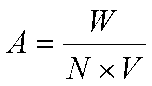
セル電圧Vはセル70内の電極特性によって決まる電圧であるため、略一定である。このため、仮にスタック数Nを一定とすると、直流電力P2の電力Wの変動に伴ってセル電流Aが変動してしまう。
セル電流Aが減少すると、セル70において発生する水素ガス及び酸素ガスの量もセル電流Aに比例して減少する。しかしながら、図4に示すように、セル70内において隔壁71を通過する水素ガス及び酸素ガスの量は、隔壁71の性質によって決まるため、水素ガスの発生量が減少しても、それほど減少しない。この結果、セル電流Aが減少して、水素ガスの発生量が減少すると、セル70から陰極ガス気液分離室33に流出する水素ガス中における酸素含有量が増加してしまう。これにより、最終的に製造される水素ガスの純度が低下してしまう。
そこで、本実施形態においては、電力Wの変動に合わせてスタック数Nを切り替える。これにより、上記数式2及び図7(c)に示すように、電力Wが変動しても、セル電流Aを略一定に保つことができる。
また、スタック数Nの変更に連動させて、電磁バルブ65を開閉することにより、駆動しているセル70によって製造された水素ガスが、バッファタンク44を介して、駆動していない洗浄塔41、陰極ガス気液分離室33及びセル70に逆流することを防止できる。
更に、スタック数Nの変更に連動させて、コンプレッサ45の処理能力を切り替えることにより、製造された水素ガスを効率的に圧縮することができる。
また、スタック数Nの変更に連動させて、電磁バルブ65を開閉することにより、駆動しているセル70によって製造された水素ガスが、バッファタンク44を介して、駆動していない洗浄塔41、陰極ガス気液分離室33及びセル70に逆流することを防止できる。
更に、スタック数Nの変更に連動させて、コンプレッサ45の処理能力を切り替えることにより、製造された水素ガスを効率的に圧縮することができる。
しかしながら、制御装置14がスタック数Nを切り替えると共にコンプレッサ45の処理能力を切り替えるタイミングと、コンプレッサ45の吸気口において水素ガスの供給量が変動するタイミングとの間には、時間差がある。具体的には、スタック数Nを増加させて、それまで使用していなかったセル70の陰極電極72と陽極電極73との間に電圧を印加しても、このセル70において水の電解反応が進行して水素ガスが生成され、この水素ガスが陰極ガス気液分離室33、洗浄塔41及びバッファタンク44を通過してコンプレッサ45の吸気口に達するまでには時間がかかる。また、スタック数Nを減少させて、それまで使用していたセル70に対する電圧の供給を停止しても、このセル70の陰極側空間74に蓄積されていた水素ガスが、陰極ガス気液分離室33、洗浄塔41及びバッファタンク44を通過してコンプレッサ45の吸気口に達し、コンプレッサ45に吸気され尽くすまでには時間がかかる。この時間差を「切替時間」という。
そこで、本実施形態においては、コンプレッサ45の吸気口側にバッファタンク44を設けている。これにより、上述の切替時間に起因した水素量の変動を吸収することができる。すなわち、スタック数Nを増加させたときは、コンプレッサ45はバッファタンク44内の水素ガスを消費し、スタック数Nを減少させたときは、セル70、陰極ガス気液分離室33及び洗浄塔41に蓄積されていた水素ガスがバッファタンク44内に蓄積される。これにより、コンプレッサ45の吸気口における水素ガスの圧力を一定範囲内に保つことができる。
なお、仮にバッファタンク44が設けられていないと、スタック数Nを増加させてコンプレッサ45の処理能力を増加させたときに、一時的にコンプレッサ45の吸気口において水素ガスが不足し、圧力が低下する。この結果、セル70の陰極側空間74の圧力が低下する。一方、陽極側空間75の圧力は変わらないため、通常運転時と比較して、陰極側空間74に対する陽極側空間75の圧力が高くなり、隔壁71を介して陽極側空間75から陰極側空間74内に進入する酸素ガス量が増加する。これにより、水素ガスの純度が低下してしまう。また、スタック数Nを減少させてコンプレッサ45の処理能力を低下させたときは、一時的にコンプレッサ45の吸気口において水素ガスが過剰となり、圧力が増加する。この結果、コンプレッサ45に過剰な負荷を与えてしまう。
上述の如く、バッファタンク44の容量は、上記切替時間において1つのセル70が生成する水素ガスの生成量以上とすることが好ましい。1つのセル70が切替時間中に生成する水素ガスの生成量以上とすることにより、スタック数Nを1だけ変化させて、1つのセル70の稼働を開始又は停止させたときに、この1つのセル70による水素ガスの供給量の変動分をバッファ44により吸収することができる。また、必要な数だけのセル70、又は、全てのセル70の稼動を同時に開始又は停止させる場合には、バッファタンク44の容量は、各々の場合において、それらに応じた分の容量とすればよい。
次に、本実施形態の効果について説明する。
本実施形態に係る水素製造システム1においては、蓄電池25により、発電施設100によって発電された交流電力P1の短周期の変動を吸収することができる。また、制御装置14がスタック制御部50を介してスイッチ49を切り替えると共に、コンプレッサ45の処理能力を調整することにより、交流電力P1の長周期の変動を吸収することができる。更に、バッファタンク44により、コンプレッサ45の吸気口における一時的な水素ガス供給量の変動を吸収することができる。これにより、交流電力P1が短周期及び長周期で変動しても、所定値以上のセル電流Aを維持することができると共に、コンプレッサ45の吸気口における水素ガスの圧力を一定範囲内に保つことができる。この結果、コンプレッサ45に過剰な負荷をかけることなく、より純度が高い水素ガスを安定して製造し続けることができる。
本実施形態に係る水素製造システム1においては、蓄電池25により、発電施設100によって発電された交流電力P1の短周期の変動を吸収することができる。また、制御装置14がスタック制御部50を介してスイッチ49を切り替えると共に、コンプレッサ45の処理能力を調整することにより、交流電力P1の長周期の変動を吸収することができる。更に、バッファタンク44により、コンプレッサ45の吸気口における一時的な水素ガス供給量の変動を吸収することができる。これにより、交流電力P1が短周期及び長周期で変動しても、所定値以上のセル電流Aを維持することができると共に、コンプレッサ45の吸気口における水素ガスの圧力を一定範囲内に保つことができる。この結果、コンプレッサ45に過剰な負荷をかけることなく、より純度が高い水素ガスを安定して製造し続けることができる。
これにより、再生可能エネルギーを利用した発電施設100から出力される交流電力P1を有効に利用して、水素ガスを製造することができる。製造された水素ガスは、貯蔵及び運搬されて、任意の時期及び場所において、例えば燃料電池により電力に再変換することができる。このように、本実施形態に係る水素製造システム1によれば、再生可能エネルギーを有効に利用することができ、社会全体の電力需要に占める再生可能エネルギーの割合を増加させることが可能となる。
また、本実施形態においては、制御装置14が電磁バルブ65を制御し、稼働しているセル70に接続された電磁バルブ65を開き、稼働していないセル70に接続された電磁バルブ65を閉じている。これにより、稼働しているセル70によって製造された水素ガスが、バッファタンク44を介して、稼働していないセル70に逆流することを防止できる。この結果、水素ガスを効率よく製造することができる。
なお、本実施形態のように、セル70のスタック数Nを切り替えて対応するのではなく、単に蓄電池25を大型化することにより、交流電力P1の長周期の変動を吸収することも考えられる。しかしながら、この場合は、蓄電池25のコストが増加してしまい、現実的ではない。例えば、水素ガスの生成量が100Nm3/h程度のアルカリ水電解装置に対しては、出力が600kW程度の蓄電池が必要となる。
また、蓄電池25を設けず、スタック数N及びコンプレッサ45の処理能力を頻繁に変更することにより、短周期の変動に対応することも考えられる。しかしながら、この場合は、大電流が流れるスイッチ49を頻繁に開閉することになり、スイッチ49が短期間で消耗してしまう。また、コンプレッサ45は機械的に動作する機器であるため、処理能力を短周期で切り替えることは困難である。
更に、バッファタンク44を設けず、コンプレッサ45の処理能力を精密に制御することにより、コンプレッサ45の吸気口における水素ガスの圧力を平滑化することも考えられる。しかしながら、この場合も、上述の如くコンプレッサ45を短周期で制御することが困難である。
更にまた、アルカリ電解方式ではなく、固体電解質膜方式によって水素ガスを製造することも考えられる。この場合は、隔壁71の替わりに、固体電解質膜を使用するため、陽極側空間75から陰極側空間74への酸素ガスの混入が少ない。しかしながら、固体電解質膜は例えば白金の粉末を含むため、高価である。また、アルカリ電解方式の場合、純水に要求される電気伝導度は10μS/cm以下であるが、固体電解質膜方式の場合、純水に要求される電気伝導度は5μS/cm以下である。すなわち、固体電解質膜方式は、アルカリ電解方式と比較して、要求される純水の純度が高い。これらの理由により、固体電解質膜方式は、アルカリ電解方式と比較してコストが高い。
(第2の実施形態)
次に、第2の実施形態について説明する。
図8は、本実施形態に係る水素製造システムを示す図である。
次に、第2の実施形態について説明する。
図8は、本実施形態に係る水素製造システムを示す図である。
図8に示すように、本実施形態に係る水素製造システム2においては、バッファタンク44が複数のサブタンク44sに分けられている。各サブタンク44sは各セル70の陰極側空間74(図4参照)に接続されている。サブタンク44sにおける入口44iから出口44oに向かう方向に対して直交する断面の面積は、水素管64の流通方向に直交する断面の面積よりも大きい。また、各サブタンク44sの容量は、コンプレッサ45の処理能力の切替時間に、1つのセル70が生成する水素ガスの生成量以上であることが好ましい。
また、サブタンク44sとコンプレッサ45との間には、サブタンク44s毎に電磁バルブ77が設けられている。そして、制御装置14が、あるセル70に直流電力P2を供給するときは、このセル70に接続された電磁バルブ65及び77を開き、制御装置14が、あるセル70に対する直流電力P2の供給を停止するときは、このセル70に接続された電磁バルブ65及び77を閉じる。
本実施形態においては、バッファタンク44が各セル70に接続された複数のサブタンク44sに区画されており、サブタンク44sとコンプレッサ45との間に電磁バルブ77が設けられていることにより、あるセル70において水の電解を停止したときに、このセル70に接続されたサブタンク44s内に、その時点までに製造された水素ガスを封入することができる。この結果、水素製造システム2全体を停止したときに、サブタンク44s内に大気が混入することを防止でき、水素製造システム2の再稼働後、短時間で水素ガスの収集を開始することができる。本実施形態における上記以外の構成、動作及び効果は、前述の第1の実施形態と同様である。
以上説明した実施形態によれば、供給される電力が不安定であっても、より純度が高い水素ガスを安定して製造できる水素製造システムを実現することができる。
以上、本発明のいくつかの実施形態を説明したが、これらの実施形態は、例として提示したものであり、発明の範囲を限定することは意図していない。これら新規な実施形態は、その他の様々な形態で実施されることが可能であり、発明の要旨を逸脱しない範囲で、種々の省略、置き換え、変更を行うことができる。これら実施形態やその変形は、発明の範囲や要旨に含まれるとともに、請求の範囲に記載された発明及びその等価物の範囲に含まれる。また、前述の各実施形態は、相互に組み合わせて実施することができる。
Claims (7)
- 外部から第1電力が供給され、直流の第2電力を出力する整流装置と、
前記第2電力が供給されてアルカリ性水溶液を電気分解する複数のセルを有する電解槽と、
前記複数のセルの陰極側に接続されたバッファタンクと、
前記バッファタンクに接続され、気体を圧縮するコンプレッサと、
前記複数のセルのそれぞれに前記第2電力を供給するか否かを選択する制御装置と、
を備えた水素製造システム。 - 前記整流装置は、前記第2電力を蓄積可能な蓄電池を有する請求項1記載の水素製造システム。
- 前記制御装置はスイッチング機能を有し、前記スイッチング機能によって、前記制御装置は前記複数のセルのそれぞれに前記第2電力を供給するか否かを選択する請求項1または2に記載の水素製造システム。
- 前記第1電力は交流電力である請求項1~3のいずれか1つに記載の水素製造システム。
- 各前記セルと前記バッファタンクとの間に接続されたバルブをさらに備え、
前記制御装置は、前記第2電力を供給する前記セルに接続された前記バルブを開き、前記第2電力を供給しない前記セルに接続された前記バルブを閉じる請求項1~4のいずれか1つに記載の水素製造システム。 - 前記バッファタンクは、前記複数のセルのそれぞれに接続された複数のサブタンクを有する請求項1~5のいずれか1つに記載の水素製造システム。
- 前記第1電力は、再生可能エネルギーを利用した発電施設によって生成される請求項1~6のいずれか1つに記載の水素製造システム。
Applications Claiming Priority (2)
| Application Number | Priority Date | Filing Date | Title |
|---|---|---|---|
| JP2016073004A JP6937096B2 (ja) | 2016-03-31 | 2016-03-31 | 水素製造システム |
| JP2016-073004 | 2016-03-31 |
Publications (1)
| Publication Number | Publication Date |
|---|---|
| WO2017169204A1 true WO2017169204A1 (ja) | 2017-10-05 |
Family
ID=59963901
Family Applications (1)
| Application Number | Title | Priority Date | Filing Date |
|---|---|---|---|
| PCT/JP2017/005272 Ceased WO2017169204A1 (ja) | 2016-03-31 | 2017-02-14 | 水素製造システム |
Country Status (2)
| Country | Link |
|---|---|
| JP (1) | JP6937096B2 (ja) |
| WO (1) | WO2017169204A1 (ja) |
Cited By (5)
| Publication number | Priority date | Publication date | Assignee | Title |
|---|---|---|---|---|
| CN111699279A (zh) * | 2018-03-22 | 2020-09-22 | 株式会社德山 | 碱性水电解装置及气体制造方法 |
| CN113088987A (zh) * | 2021-02-25 | 2021-07-09 | 四川大学 | 基于质电耦合直接海水捕集制氢装置、系统及方法 |
| CN114075674A (zh) * | 2021-12-06 | 2022-02-22 | 中冶南方工程技术有限公司 | 一种回收电解槽清洗带钢逸出气体的装置 |
| JP2022045497A (ja) * | 2020-09-09 | 2022-03-22 | 住友電気工業株式会社 | 水素製造システム、制御装置、水素発生装置の制御方法、及びコンピュータプログラム |
| CN114807959A (zh) * | 2022-03-15 | 2022-07-29 | 中国船舶重工集团公司第七一八研究所 | 一种适用于宽功率波动的高效率制氢系统 |
Families Citing this family (7)
| Publication number | Priority date | Publication date | Assignee | Title |
|---|---|---|---|---|
| CN107740133A (zh) * | 2017-10-19 | 2018-02-27 | 杭州泰博科技有限公司 | 光催化阴极电极分解水制氢气的装置及其方法 |
| EP3831986B1 (en) | 2018-07-27 | 2026-01-28 | Tokuyama Corporation | Gas production device and gas production method |
| KR102192913B1 (ko) * | 2019-04-30 | 2020-12-18 | 주식회사 메타팩 | 공동주택을 이용한 수소 생산 시스템 |
| JP7512068B2 (ja) * | 2020-04-08 | 2024-07-08 | 株式会社神鋼環境ソリューション | 水素ガス製造設備および水素ガス製造方法 |
| EP4257732A4 (en) * | 2020-12-07 | 2025-06-11 | Asahi Kasei Kabushiki Kaisha | Alkaline water electrolysis plant and method for operating an alkaline water electrolysis plant |
| DE102021104027A1 (de) | 2021-02-19 | 2022-08-25 | HYDRO-GENIUS GmbH | Modular aufgebaute Elektrolyseanlage |
| WO2025099844A1 (ja) * | 2023-11-08 | 2025-05-15 | 日本碍子株式会社 | 電解セルシステム及びその運転方法 |
Citations (1)
| Publication number | Priority date | Publication date | Assignee | Title |
|---|---|---|---|---|
| JP2013049600A (ja) * | 2011-08-31 | 2013-03-14 | Hitachi Ltd | 再生可能エネルギ貯蔵システム |
Family Cites Families (3)
| Publication number | Priority date | Publication date | Assignee | Title |
|---|---|---|---|---|
| JPH0759756B2 (ja) * | 1987-04-08 | 1995-06-28 | 株式会社日立製作所 | 水素酸素発生装置 |
| JP2007284730A (ja) * | 2006-04-14 | 2007-11-01 | Star Energy:Kk | 水素・酸素ガス発生供給装置 |
| JP6231296B2 (ja) * | 2013-05-16 | 2017-11-15 | エア・ウォーター株式会社 | ガスの減湿装置および方法 |
-
2016
- 2016-03-31 JP JP2016073004A patent/JP6937096B2/ja active Active
-
2017
- 2017-02-14 WO PCT/JP2017/005272 patent/WO2017169204A1/ja not_active Ceased
Patent Citations (1)
| Publication number | Priority date | Publication date | Assignee | Title |
|---|---|---|---|---|
| JP2013049600A (ja) * | 2011-08-31 | 2013-03-14 | Hitachi Ltd | 再生可能エネルギ貯蔵システム |
Cited By (10)
| Publication number | Priority date | Publication date | Assignee | Title |
|---|---|---|---|---|
| CN111699279A (zh) * | 2018-03-22 | 2020-09-22 | 株式会社德山 | 碱性水电解装置及气体制造方法 |
| EP3770304A4 (en) * | 2018-03-22 | 2021-05-05 | Tokuyama Corporation | ALKALINE WATER ELECTROLYSIS DEVICE AND GAS GENERATING METHOD |
| US11220755B2 (en) | 2018-03-22 | 2022-01-11 | Tokuyama Corporation | Apparatus for alkaline water electrolysis, and gas production method |
| CN111699279B (zh) * | 2018-03-22 | 2022-06-24 | 株式会社德山 | 碱性水电解装置及气体制造方法 |
| JP2022045497A (ja) * | 2020-09-09 | 2022-03-22 | 住友電気工業株式会社 | 水素製造システム、制御装置、水素発生装置の制御方法、及びコンピュータプログラム |
| JP7494665B2 (ja) | 2020-09-09 | 2024-06-04 | 住友電気工業株式会社 | 水素製造システム、制御装置、水素発生装置の制御方法、及びコンピュータプログラム |
| CN113088987A (zh) * | 2021-02-25 | 2021-07-09 | 四川大学 | 基于质电耦合直接海水捕集制氢装置、系统及方法 |
| CN114075674A (zh) * | 2021-12-06 | 2022-02-22 | 中冶南方工程技术有限公司 | 一种回收电解槽清洗带钢逸出气体的装置 |
| CN114807959A (zh) * | 2022-03-15 | 2022-07-29 | 中国船舶重工集团公司第七一八研究所 | 一种适用于宽功率波动的高效率制氢系统 |
| CN114807959B (zh) * | 2022-03-15 | 2023-10-27 | 中国船舶重工集团公司第七一八研究所 | 一种适用于宽功率波动的高效率制氢系统 |
Also Published As
| Publication number | Publication date |
|---|---|
| JP6937096B2 (ja) | 2021-09-22 |
| JP2017179557A (ja) | 2017-10-05 |
Similar Documents
| Publication | Publication Date | Title |
|---|---|---|
| JP6937096B2 (ja) | 水素製造システム | |
| CA3117925C (en) | Method of producing hydrogen | |
| CN106784960B (zh) | 一种一体式可逆燃料电池系统 | |
| US10760167B2 (en) | Electrolytic cell and hydrogen production apparatus | |
| CN105862066B (zh) | 一种高压质子膜水电解装置及方法 | |
| AU2012228513B2 (en) | Hydrogen offloading in an electrochemical generator unit including a hydrogen fuel cell | |
| CN114592207A (zh) | 一种适应快速宽功率波动的电解制氢系统及控制方法 | |
| JP2019200839A (ja) | 発電システム | |
| JP6721537B2 (ja) | 水素電解製造用電解液タンク、水素電解製造用電解装置、および水素製造システム | |
| CN113193217A (zh) | 一种氢氧燃料电池系统 | |
| CN103069052A (zh) | 氢制造系统 | |
| WO2015159817A1 (ja) | 水素ガス発生システム | |
| CN109617215A (zh) | 一种分布式光伏发电氢储能系统及方法 | |
| JP2013049600A (ja) | 再生可能エネルギ貯蔵システム | |
| KR101749664B1 (ko) | 안전하고 안정된 수소 저장부를 갖는 에너지 유닛 | |
| US20230279569A1 (en) | Arrangement to optimize the production of hydrogen | |
| US20020195349A1 (en) | Method and apparatus for the storage and redistribution of electrical energy | |
| US20090130539A1 (en) | Electric power grid buffer | |
| US11339480B2 (en) | Electrolytic cell and hydrogen production apparatus | |
| KR102259360B1 (ko) | 심층수 기반 발전용 수소생산시스템 | |
| JP4796798B2 (ja) | 水素供給方法 | |
| JP6544628B2 (ja) | 水の電気分解装置 | |
| JP2020079450A (ja) | 電解槽及び水素製造装置 | |
| JP2004071487A (ja) | 分散型発電システム | |
| CN108172951B (zh) | 一种锌空气电池系统及其控制方法 |
Legal Events
| Date | Code | Title | Description |
|---|---|---|---|
| NENP | Non-entry into the national phase |
Ref country code: DE |
|
| 121 | Ep: the epo has been informed by wipo that ep was designated in this application |
Ref document number: 17773752 Country of ref document: EP Kind code of ref document: A1 |
|
| 122 | Ep: pct application non-entry in european phase |
Ref document number: 17773752 Country of ref document: EP Kind code of ref document: A1 |