WO2017169198A1 - Lid for tube for life sciences, tube set for life sciences, and cell separation method - Google Patents
Lid for tube for life sciences, tube set for life sciences, and cell separation method Download PDFInfo
- Publication number
- WO2017169198A1 WO2017169198A1 PCT/JP2017/005200 JP2017005200W WO2017169198A1 WO 2017169198 A1 WO2017169198 A1 WO 2017169198A1 JP 2017005200 W JP2017005200 W JP 2017005200W WO 2017169198 A1 WO2017169198 A1 WO 2017169198A1
- Authority
- WO
- WIPO (PCT)
- Prior art keywords
- tube
- life science
- lid
- cell
- cells
- Prior art date
Links
Images


Classifications
-
- C—CHEMISTRY; METALLURGY
- C12—BIOCHEMISTRY; BEER; SPIRITS; WINE; VINEGAR; MICROBIOLOGY; ENZYMOLOGY; MUTATION OR GENETIC ENGINEERING
- C12M—APPARATUS FOR ENZYMOLOGY OR MICROBIOLOGY; APPARATUS FOR CULTURING MICROORGANISMS FOR PRODUCING BIOMASS, FOR GROWING CELLS OR FOR OBTAINING FERMENTATION OR METABOLIC PRODUCTS, i.e. BIOREACTORS OR FERMENTERS
- C12M1/00—Apparatus for enzymology or microbiology
- C12M1/24—Apparatus for enzymology or microbiology tube or bottle type
-
- C—CHEMISTRY; METALLURGY
- C12—BIOCHEMISTRY; BEER; SPIRITS; WINE; VINEGAR; MICROBIOLOGY; ENZYMOLOGY; MUTATION OR GENETIC ENGINEERING
- C12M—APPARATUS FOR ENZYMOLOGY OR MICROBIOLOGY; APPARATUS FOR CULTURING MICROORGANISMS FOR PRODUCING BIOMASS, FOR GROWING CELLS OR FOR OBTAINING FERMENTATION OR METABOLIC PRODUCTS, i.e. BIOREACTORS OR FERMENTERS
- C12M1/00—Apparatus for enzymology or microbiology
- C12M1/26—Inoculator or sampler
- C12M1/28—Inoculator or sampler being part of container
-
- C—CHEMISTRY; METALLURGY
- C12—BIOCHEMISTRY; BEER; SPIRITS; WINE; VINEGAR; MICROBIOLOGY; ENZYMOLOGY; MUTATION OR GENETIC ENGINEERING
- C12N—MICROORGANISMS OR ENZYMES; COMPOSITIONS THEREOF; PROPAGATING, PRESERVING, OR MAINTAINING MICROORGANISMS; MUTATION OR GENETIC ENGINEERING; CULTURE MEDIA
- C12N1/00—Microorganisms, e.g. protozoa; Compositions thereof; Processes of propagating, maintaining or preserving microorganisms or compositions thereof; Processes of preparing or isolating a composition containing a microorganism; Culture media therefor
-
- C—CHEMISTRY; METALLURGY
- C12—BIOCHEMISTRY; BEER; SPIRITS; WINE; VINEGAR; MICROBIOLOGY; ENZYMOLOGY; MUTATION OR GENETIC ENGINEERING
- C12Q—MEASURING OR TESTING PROCESSES INVOLVING ENZYMES, NUCLEIC ACIDS OR MICROORGANISMS; COMPOSITIONS OR TEST PAPERS THEREFOR; PROCESSES OF PREPARING SUCH COMPOSITIONS; CONDITION-RESPONSIVE CONTROL IN MICROBIOLOGICAL OR ENZYMOLOGICAL PROCESSES
- C12Q1/00—Measuring or testing processes involving enzymes, nucleic acids or microorganisms; Compositions therefor; Processes of preparing such compositions
- C12Q1/68—Measuring or testing processes involving enzymes, nucleic acids or microorganisms; Compositions therefor; Processes of preparing such compositions involving nucleic acids
-
- G—PHYSICS
- G01—MEASURING; TESTING
- G01N—INVESTIGATING OR ANALYSING MATERIALS BY DETERMINING THEIR CHEMICAL OR PHYSICAL PROPERTIES
- G01N21/00—Investigating or analysing materials by the use of optical means, i.e. using sub-millimetre waves, infrared, visible or ultraviolet light
- G01N21/01—Arrangements or apparatus for facilitating the optical investigation
-
- G—PHYSICS
- G01—MEASURING; TESTING
- G01N—INVESTIGATING OR ANALYSING MATERIALS BY DETERMINING THEIR CHEMICAL OR PHYSICAL PROPERTIES
- G01N21/00—Investigating or analysing materials by the use of optical means, i.e. using sub-millimetre waves, infrared, visible or ultraviolet light
- G01N21/17—Systems in which incident light is modified in accordance with the properties of the material investigated
-
- G—PHYSICS
- G01—MEASURING; TESTING
- G01N—INVESTIGATING OR ANALYSING MATERIALS BY DETERMINING THEIR CHEMICAL OR PHYSICAL PROPERTIES
- G01N33/00—Investigating or analysing materials by specific methods not covered by groups G01N1/00 - G01N31/00
- G01N33/48—Biological material, e.g. blood, urine; Haemocytometers
Definitions
- the present invention relates to a life science tube lid, a life science tube set, and a cell selection method, and more particularly, to a life science tube lid, a life science tube set, and a life science tube suitable for cell image analysis.
- the present invention relates to a method for sorting cells using a lid.
- the target cells are separated by flow cytometry.
- flow cytometry fine cells are dispersed in a fluid, the fluid is finely flowed, individual cells are optically analyzed, and the obtained cells are judged and sorted based on the analysis results. Is.
- a plurality of cells are dropped together on a well slide, dropped into a minute well, photographed and analyzed, and target cells are identified. Thereafter, the specified target cell is sucked with a capillary and transferred to a PCR (polymerase chain reaction) plate or tube.
- PCR polymerase chain reaction
- Patent Document 1 describes a reaction container having a removable lid on a tube used for PCR.
- the present invention has been made in view of such circumstances, and is a life science tube that can efficiently perform subsequent analysis or preprocessing of analysis by performing image analysis using a lid.
- An object of the present invention is to provide a lid, a tube set for life science, and a cell sorting method.
- the present invention is a life science tube lid having a recess on the side of the life science tube, the bottom surface of the recess being flat, and a circular or quadrangular or more polygonal shape.
- a lid for a life science tube having an inclined surface whose side surface is widened from the bottom surface toward the opening.
- the lid of the tube for life science of the present invention has a recess on the surface side on which the tube for life science is mounted, and by flattening the bottom surface of this recess, An image of the specimen can be taken.
- By flattening the bottom surface of the concave portion of the lid it is possible to focus on the specimen in the concave portion, and a good image can be taken.
- the opening portion can be widened and the specimen can easily enter the concave portion. Further, by narrowing toward the bottom surface, the size of the bottom surface can be reduced, and the size of the bottom surface with respect to the specimen can be set within a predetermined range. Therefore, in the image analysis of the specimen, the entire bottom surface can be imaged by photographing with one visual field, and the imaging and the image analysis of the specimen can be performed efficiently.
- the side surface an inclined surface that expands toward the opening, it is possible to easily remove bubbles in the culture solution, and it is possible to prevent light from being refracted by the bubbles and to obtain a good image. An image can be taken.
- life science refers to handling of cells and biomolecules, and more specifically includes cell culture, detection, separation, purification, analysis and evaluation, and biomolecules. This refers to those used for the synthesis, detection, separation, purification, analysis and evaluation of compounds, and the “life science tube” refers to a container used for life science applications.
- the “life science tube side” is the surface on which the life science tube is mounted. When used with the life science tube, it forms a space between the lid of the life science tube and the tube. It means the surface side.
- the side surface preferably has two or more inclined surfaces having different angles with respect to the bottom surface.
- the degree of freedom in designing the side surface of the concave portion can be increased by making the side surface of the concave portion of the lid into two or more inclined surfaces having different angles with respect to the bottom surface. For example, by increasing the angle on the opening side of the recess, the specimen can be more easily entered into the recess. Further, by reducing the angle of the bottom surface side of the side surface, the bottom surface can be narrowed, and the bottom surface can be imaged with a single image even if the magnification during imaging is increased. By increasing the angle on the bottom side of the side surface, the sample introduced into the recess can be prevented from staying on the side surface, and can be dropped to the bottom surface.
- the size of the bottom surface is preferably 0.05 mm ⁇ or more and 1 mm ⁇ or less when approximated to a circumscribed circle.
- the entire bottom surface is captured by a single image by capturing with an objective lens having a magnification (5 to 63 times) used for capturing normal images. can do. Therefore, it is possible to efficiently perform imaging and image analysis of the specimen.
- the transmittance for light having a wavelength of 350 nm or more and 800 nm or less is preferably 60% or more.
- a good image can be taken by setting the transmittance of the material used for the lid of the life science tube to light having the above wavelength to 60% or more.
- it is preferably formed of acrylic resin, polypropylene, or polystyrene.
- the material used for the lid of the life science tube is limited.
- acrylic resin, polypropylene, or polystyrene By using acrylic resin, polypropylene, or polystyrene, the transparency of the lid can be obtained and a good image is taken. be able to.
- heat resistance can be ensured by using polypropylene or polystyrene, even if the next process is a process of applying a temperature, for example, a PCR process, the process is performed using the lid as it is. It can be carried out.
- the surface of the recess is subjected to a low cell adhesion treatment.
- the present invention provides a life science tube set comprising the life science tube lid described above and a life science tube.
- the specimen subjected to image analysis using the lid of the tube for life science described above is moved to the tube for life science used in the set, and the subsequent processing is performed.
- the subsequent processing is performed.
- one life science tube set having a lid can perform sample image analysis and subsequent processing, and can be efficiently operated.
- the life science tube is preferably a PCR tube or a low protein adsorption tube.
- This embodiment describes a specific example of a life science tube, and a PCR tube and a low protein adsorption tube can be used as the life science tube.
- the present invention is based on a step of sorting cells into a lid of a tube for life science, a step of capturing the sorted cells, obtaining a cell image, and a cell image. And a method for selecting cells having a step of selecting a target cell.
- the target cells can be sorted with high accuracy by sorting the target cells based on the cell image using the lid of the life science tube, and for life science.
- the target cell can be easily transferred to the tube.
- the lid of the life science tube is used for image analysis of the cell, the target cell is moved to the life science tube, and the target cell is processed in the life science tube.
- Image analysis and subsequent processing can be performed by one life science tube provided.
- the step of treating the target cell is preferably a PCR treatment.
- This aspect limits the process of processing the target cell and can perform PCR treatment.
- the lid of the life science tube has a recess on the side of the life science tube, the bottom surface of the recess is a circle or a polygon having a quadrangle or more, and the side surface faces the opening from the bottom surface. It is preferable that it consists of the inclined surface of the direction which spreads.
- the recess it is possible to capture the image of the cells in the recess by having the recess on the surface side where the life science tube is mounted of the lid of the life science tube and flattening the bottom surface of the recess. it can. By flattening the bottom surface of the concave portion of the lid, it is possible to focus on the cells in the concave portion and to capture a good image.
- the opening portion can be widened, and cells can easily enter the concave portion.
- the size of the bottom surface can be reduced, and the size of the bottom surface with respect to the cells can be within a predetermined range. Therefore, in the image analysis of the specimen, the entire bottom surface can be imaged with a single image, and the imaging and the image analysis of the specimen can be performed efficiently.
- the side surface an inclined surface that expands toward the opening, it is possible to easily remove bubbles in the culture solution, and it is possible to prevent light from being refracted by the bubbles and to obtain a good image. An image can be taken.
- the diameter of the bottom surface approximates to a circumscribed circle is 0.05 mm ⁇ to 1 mm ⁇ .
- the entire bottom surface can be imaged with one field of view. Therefore, imaging and image analysis can be performed efficiently.
- the magnification of the objective lens for photographing is 5 to 63 times, and the size of the bottom surface approximates a circumscribed circle in the image photographing region. It is preferable that the diameter at the time is shorter than the length of the short side of the two orthogonal sides of the image capturing region and is 1 ⁇ 2 or more of the length of the short side.
- the size of the bottom surface (diameter approximated to a circumscribed circle) is set to two orthogonal sides of the image shooting region.
- the specimen (cell) to be observed can be introduced into the recess and image analysis can be performed.
- image analysis By using it as a set with a life science tube, it is possible to perform image analysis of the specimen and subsequent processing with a single life science tube set having a lid, and to perform operations efficiently.
- the target cell can be selected with high accuracy by selecting the target cell by image analysis using the lid of the life science tube. Cells can be easily moved.
- the lid of the tube for life science, the tube set for life science, and the cell sorting method according to the present invention will be described with reference to the accompanying drawings.
- “to” is used to mean that the numerical values described before and after it are included as a lower limit value and an upper limit value.
- cells will be described as an example, but the uses of the life science tube cover and life science tube set of the present invention are not limited to cells, and can be used for compounds containing biomolecules.
- an analysis apparatus including an imaging apparatus that captures an image by applying the lid of the tube for life science of the present embodiment (hereinafter also simply referred to as “lid”) will be described.
- FIG. 1 is a schematic configuration diagram showing the configuration of an apparatus for imaging target cells sorted on the lid of a life science tube and acquiring optical information from the cells in the sorting step.
- the analyzer is capable of acquiring fluorescence emission information from fluorescent dyes labeled on cells sorted by antigen-antibody reaction or the like, and acquiring light transmission images of cells by visible light.
- the analysis device 10 shown in FIG. 1 is a fluorescent excitation light source device 12 that emits light for measuring fluorescence emitted from a target cell, and a light that emits light (visible light) for measuring transmitted light of the cell.
- a filter group (filter cube) 28 and an imaging device 30 that images fluorescence and transmitted light from the cells 16 are provided.
- a high-pressure mercury lamp, a high-pressure xenon lamp, an LED (light emitting diode), a LASER (light amplification by radiation, radiation, etc.) can be used. By using these light sources, it is possible to reliably perform analysis with high accuracy by narrowing the wavelength region of the irradiation light with which the cells 16 are irradiated.
- a tungsten lamp, a halogen lamp, a white LED, or the like can be used. Even when these light sources are used, the cell 16 can be irradiated with light having a target wavelength by transmitting only the target wavelength with the excitation filter 22.
- the bright field light source device 14 the same light source as the fluorescence excitation light source device 12 can be used.
- the tray 19 includes a plate 18 and a lid 32 for storing the sorted cells 16.
- the lid 32 has a recess on the side where a life science tube (hereinafter also simply referred to as “tube”) is mounted, and accommodates the cells sorted in the recess.
- a life science tube hereinafter also simply referred to as “tube”
- the side of the life science tube lid 32 on which the life science tube is mounted is referred to as the surface of the life science tube lid, and the opposite side is referred to as the back surface.
- the plate 18 is a sample stage that holds the lid 32, and since the cells 16 are imaged from the back side of the lid 32, the plate 18 has a through hole at the position of the plate 18 corresponding to the bottom surface of the concave portion of the lid 32.
- it is made of a transparent material that can transmit light.
- FIG. 2 is a diagram showing another aspect of the tray.
- a tray 319 shown in FIG. 2 is different from the tray 19 shown in FIG. 1 in that a plate 318 and a lid 332 are integrally formed.
- a tray used in the analysis apparatus 10 as shown in FIG. 2, a tray in which a plate 318 and a lid 332 are integrated can be used.
- the plate 318 and the lid 332 can be manufactured at a time by injection molding, and the lid 332 can be arranged with high accuracy.
- the tray can be manufactured at a low cost.
- the lens 20 transmits fluorescence emitted from the cells 16 by the light output from the fluorescence excitation light source device 12 and transmitted light transmitted through the cells 16 by the light output from the bright field light source device 14. Expanding.
- the lens 20 can be a lens generally used for optical applications.
- the filter group 28 includes an excitation filter 22, a dichroic mirror 24, and a fluorescence filter 26.
- a filter cube For example, Zeiss Filter Set49 (DAPI) can be used.
- the light emitted from the fluorescence excitation light source device 12 transmits only light in the target wavelength region through the excitation filter 22.
- the light transmitted through the excitation filter 22 is reflected by the dichroic mirror 24 toward the tray 19.
- the fluorescence emitted from the cells 16 generated by the excitation light emitted from the fluorescence excitation light source device 12 is imaged by the imaging device 30 via the lens 20, the dichroic mirror 24, and the fluorescence filter 26.
- the fluorescence emitted by the excitation light has a fluorescence wavelength region on the longer wavelength side than the excitation light wavelength region, only the fluorescence emission can be transmitted by using the dichroic mirror 24. Furthermore, by using the fluorescence filter 26 that transmits only the fluorescence without transmitting the excitation light, the imaging device 30 can capture an image with only the information of the fluorescence emitted from the cell 16. Therefore, by transmitting only the fluorescence with the fluorescence filter 26, the image captured by the imaging device 30 can be acquired without being influenced by the excitation light, and the accuracy of the inspection is improved by the fluorescence emission information. Can be made.
- Fluorescence imaging with light emitted from the fluorescence excitation light source device 12 is usually immunostained with a plurality of types of dyes in order to obtain a plurality of information for one cell according to the purpose of cell inspection.
- the fluorescence from each dye of immunostained cells is photographed using a filter group having transmission characteristics or reflection characteristics suitable for the fluorescence wavelength of each dye, so that optical wavelengths of different wavelengths can be obtained. Information can be obtained.
- the transmitted light of the cell 16 with the light source device 14 for bright fields it images with the filter group 28 removed. Thereby, the transmitted light can be imaged by the imaging device 30.
- the imaging device 30 is not particularly limited as long as it can capture the fluorescence or transmitted light of the cells 16 in the lid 32 on the tray 19.
- a CCD (charge-coupled device) camera can be used.
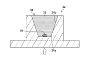
- FIG. 3 is a cross-sectional view showing the shape of the lid 32 of the life science tube used in the present embodiment.
- the material of the lid 32 preferably has conditions such as being transparent to these lights, not being autofluorescent, and not being scattered.
- the bottom surface 34a of the recess 34 of the lid 32 has a flat shape. By flattening the bottom surface 34a of the recess 34, it becomes possible to focus on the cell 16, and image analysis of the cell 16 existing on the bottom surface 34a can be performed with high accuracy.
- the shape of the bottom surface 34a is a circle or a polygon more than a quadrangle. Further, when the size of the bottom surface 34a approximates to a circle circumscribing the bottom surface 34a, the diameter L of the circle is preferably 0.05 mm ⁇ to 1 mm ⁇ , and more preferably 0.1 mm ⁇ to 0.5 mm ⁇ . More preferably, it is 0.2 mm ⁇ or more and 0.4 mm ⁇ or less. In FIG. 3, the bottom surface 34a is described as a circle.
- the imaging of the cells 16 can be performed by performing bright field imaging with fluorescence information from each dye, and superimposing each image after imaging as necessary to analyze the cells.
- FIG. 4 is a diagram showing the relationship between the image capturing area 40 captured by the microscope and the size of the bottom surface 34a of the recess 34.
- the size of the bottom surface 34a is such that the diameter L of the bottom surface 34a is shorter than the length of the short side d among the two orthogonal sides, the long side e, and the short side d of the image capturing region 40, and the length of the short side d. It is preferable to set it to 1/2 or more.
- the flat bottom surface 34a of the lid in which the cells are accommodated can be formed within the image capturing region 40 according to the size of a preferable cell image and 1 It is possible to take a picture of cells in the field of view.
- the size of the image photographing area 40 is determined by the magnification of the objective lens of the microscope and the photographing camera.
- the bottom surface 34a can be imaged by one piece in the image capturing area 40 by setting the diameter L of the bottom surface to 0.4 mm ⁇ . .
- the diameter L of the bottom surface is 0.2 mm ⁇ for a 40 ⁇ objective lens, the diameter L is 0.1 mm ⁇ for a 63 ⁇ objective lens, and the diameter L is 1 mm ⁇ for a 10 ⁇ objective lens.
- the bottom surface 34a can be imaged with one image.
- the magnification is preferably a high magnification.
- the magnification of the objective lens starts to affect the accuracy of image analysis due to unevenness on the back side of the lid 32 and the like, and the magnification of the objective lens is about 20 times. Is preferred.
- the side surface 34b of the concave portion 34 is formed obliquely in a direction extending from the bottom surface 34a toward the opening, and has a tapered shape.
- the thickness t of the bottom surface 34a of the lid 32 is preferably 0.2 mm or more and 1 mm or less. As shown in FIG. 1, since the cell 16 is imaged from the back side (bottom side) of the lid 32, the lens 20 is brought closer to the cell 16 if the thickness of the bottom surface 34a is 1 mm or less. This is preferable because it enables photographing of cells at a high magnification. Further, when the depth is 0.2 mm or more, it becomes possible to set the depth of focus in a narrow range, and even if there is even a slight scratch on the back side of the lid 32, the image of the image that is captured because the focus of the scratch is shifted. A scratch image is not projected, and only a cell image can be taken, which is preferable.
- the thickness t of the bottom surface 34a is more preferably 0.3 mm or more and 0.5 mm or less, and further preferably 0.4 mm.
- the material of the lid 32 is preferably a material that easily transmits light when an image is taken. Specifically, a material selected from acrylic resin, polypropylene, or polystyrene can be used.
- the lid 32 made of these materials preferably has a transmittance for light having a wavelength of 350 nm or more and 800 nm or less of 60% or more, more preferably 70% or more, and further preferably 80% or more. preferable. From the viewpoint of light transmittance, it is preferable to use acrylic resin or polypropylene.
- the surface (bottom surface 34a and side surface 34b) of the recess 34 is subjected to a low cell adhesion treatment.
- the cell low adhesion treatment is treatment for preventing cells, ie, proteins, from adhering to the bottom surface 34a and the side surface 34b in the recess 34, and is a treatment for coating the surface with a material having a property of preventing protein adsorption.
- the cause of protein adsorption into the recess 34 is mainly due to the hydrophobic interaction in which the hydrophobic group on the surface of the resin, which is the material of the lid 32, and the hydrophobic group in the protein bind to each other. It is possible to obtain a surface subjected to a low cell adhesion treatment by coating a material having
- a polymer containing a phosphocholine group for example, Lipidure (registered trademark) (also known as MPC (2-methacryloyloxyethylphosphorylcholine) polymer) (manufactured by NOF Corporation)), polyvinylpyrrolidone, polyethylene glycol, PVA (polyvinyl alcohol) hydrogel, BSA (Bovine serum alcohol), etc.
- a coating method coating can be performed by dipping in a dispersion obtained by dispersing the above materials in a solvent and then drying.
- the solvent for example, in the case of lipid, ethanol can be used. By mixing lipid in ethanol at a ratio of 0.5 wt%, a dispersion is obtained.
- the surface of the recess 34 By subjecting the surface of the recess 34 to low cell adhesion, it is possible to prevent the cells from adhering to the side surface 34b before reaching the bottom surface 34a when sorting cells into the recess 34 by flow cytometry or the like. . Further, after the image analysis, when the cell is moved to the tube, it can be easily moved to the tube without adhering to the bottom surface 34a.
- the low cell adhesion treatment can also be performed by stabilizing an enzyme that decomposes the attached protein.
- FIG. 5 is a cross-sectional view showing the shape of a life science tube lid 132 according to another embodiment.
- Side face of the recess 134 of the lid 132 shown in FIG. 5 is a side has an angle theta B relative to the bottom surface 134a 134b, and, and a side surface 134c having an angle theta C with respect to the bottom surface 134a.
- the side surfaces can be bent in multiple stages and formed by side surfaces 134b and 134c that are two-level inclined surfaces having different angles ⁇ B and ⁇ C with respect to the bottom surface 134a. By forming the side surface with two inclined surfaces, the degree of freedom in designing the side surface in the recess 134 can be increased.
- the side surface is a two-step inclined surface, but the number of steps is not particularly limited, and may be three or more inclined surfaces.
- FIG. 6 is a cross-sectional view showing the shape of a life science tube lid 232 according to still another embodiment.
- the lid 232 shown in FIG. 6 is different from the other embodiments in that a spacer 236 is provided in the recess.
- ⁇ Tube set for life science The lid of the above-described life science tube is used as a life science tube set together with the life science tube.
- tubes for life science use tubes used for applications such as cell culture, detection, separation, purification, analysis and evaluation, and synthesis, detection, separation, purification, analysis and evaluation of compounds containing biomolecules. Can do.
- a low protein adsorption tube that reduces sample adhesion to the container can be used.
- a PCR tube for performing PCR treatment can be used.
- FIG. 7 to 9 are process diagrams showing processes in the cell sorting direction.
- FIG. 10 is a diagram illustrating a process of attaching a life science tube
- FIG. 11 is a diagram illustrating a process of moving a target cell to the life science tube.
- the step of sorting the cells into the lid of the tube for life science the step of capturing the sorted cells, obtaining the cell image, and the cell image, Selecting a target cell.
- a processing step a processing step.
- the culture solution 38 is dropped into the recess 34 of the lid 32.
- the cells 16 are sorted into the recess 34 having the culture solution 38.
- the step of separating target cells from a plurality of cells can be performed, for example, by flow cytometry.
- a sample liquid containing a measurement target substance such as a measurement target cell is flowed to the center side of the laminar flow of the sheath liquid in the flow cell, and the measurement target substance is irradiated with laser light in the optical detection unit, thereby By measuring the generated scattered light and fluorescence, the size and structure of the substance to be measured are measured.
- the measurement parameters in the optical detection unit include forward scattered light, side scattered light, and fluorescence. In forward scattered light, the size of the measurement target is measured, and the structure of the measurement target substance is determined by the side scattered light and fluorescence. Etc. can be measured.
- the target cells are sorted into the lid on the tray by the sorting system.
- the sample / sheath fluid is designed to flow from top to bottom, and it drops out of the nozzle at the tip of the flow cell in laminar flow.
- a vertical vibration is applied to the entire flow cell or the inside of the flow cell by using a transducer (vibrator) so that the sample / sheath liquid that has flowed out of the flow cell becomes a droplet from the middle.
- the sorting conditions using the measurement parameters in the optical detection unit it is determined whether or not the cells are to be sorted, and the whole sample / sheath solution is charged with + or ⁇ just before it becomes a droplet. After that, the droplet falls between the two deflecting plates, the + charged droplet is drawn to the negative plate side, and the negative charged droplet is drawn to the positive plate side, on the tray in the cell collection section.
- Cells can be sorted into each lid.
- FIG. 9 is a diagram illustrating a process of acquiring a cell image.
- the apparatus shown in FIG. 1 can be used as an apparatus for capturing a cell image.
- the lid 32 of the tube for life science used in the present embodiment has a flat bottom surface 34a of the recess 34 and a circular shape or a quadrilateral or more polygonal shape, and the side surface 34b extends from the bottom surface 34a to the opening. It is formed obliquely in the direction that spreads out. Therefore, it is suitable for capturing an image of the cell 16 present on the bottom surface 34a, and a good cell image can be obtained efficiently and efficiently using the lid 32 of the life science tube of the present embodiment.
- Step of selecting target cells includes, for example, the presence or absence of nuclei, the size of the nuclei, the shape of the nuclei (ratio of the area of the nuclear region to the area of the cytoplasm, the degree of circularity of the nuclei), Peak intensity, fluorescence intensity peak value, average value, luminance distribution (whether the cell membrane is uniformly fluorescent or locally intensely fluorescent), the degree of absorption for transmitted light of a specific wavelength (hemoglobin or leukocyte) Determination), spectral characteristics (absorption coefficients with respect to wavelengths of reduced hemoglobin [Hb] and oxidized hemoglobin [HbO 2 ]) resulting from a difference in oxygen affinity of hemoglobin, and the like.
- a viewpoint (cell shape, absorption of transmitted light, etc.) for selecting a target cell and a cell different from the target cell deviated from the selection is determined. Then, the degree of the viewpoint is converted into a numerical value, and from these measured numerical values, a numerical range indicating the probability of being a target cell and a threshold value indicating the range are determined, and the threshold value is determined as a selection reference value.
- a plurality of viewpoints to be selected are determined in advance, and a threshold value for each viewpoint is obtained to determine a selection reference value. Cells that satisfy all of the plurality of reference values thus determined can be selected as target cells. For example, if the target cell is a nucleated red blood cell or the like, the selection method described in International Publication WO2014023093 or International Publication WO2014021311 can be used.
- FIG. 10 is a diagram illustrating a process of attaching a life science tube.
- the tube 50 may be attached only to the lid 32 from which the target cells and the sorted cells 16 are sorted, or the tube 50 may be attached to all the lids 32. .
- the process of attaching the life science tube can be performed using a dedicated device.
- the tube 50 When the tube 50 is attached only to the lid 32 from which the cells 16 sorted out as the target cells are collected, only the target cell to which the tubes 50 are attached performs the next step. Therefore, it is preferable to associate the tube 50 with the information of the cells 16 in the tube 50.
- As a method of associating the information of the cells 16 with the lid 32 or the tube 50 there is a method of marking the arrangement information of the lid 32 arranged on the tray 19 on the lid 32 with characters. As a description example of the arrangement information, if “C4”, it means the fourth row and fourth column of the plate, and if “D4”, it means the fourth column of the D row.
- cell information instead of the arrangement information of the tray 19, cell information may be printed with a QR code (registered trademark).
- RFID radio frequency identifier
- FIG. 11 is a diagram illustrating a process of moving the target cell to the life science tube.
- the cell 16 is moved from the lid 32 to the tube 50 by, for example, moving the cell 16 together with the culture solution 38 into the tube 50 by inverting and centrifuging the tube 50 after attaching the tube 50 to the lid 32. it can.
- the step of moving the cells to the life science tube can be performed using a dedicated device.
- the target cell is processed.
- the process for treating the target cell include PCR treatment.
- the PCR treatment is a method of amplifying a specific region of a DNA (deoxyribonucleic acid) molecule, and can be performed, for example, by the following method.
- the PCR process is not limited to the following method.
- the process of processing the target cell is not limited to the PCR process, and other processes can be performed.
- reaction solution is rapidly cooled to about 60 ° C., the single-stranded DNA and primer are heated (annealed) to a predetermined temperature, and the single-stranded DNA and primer are heated.
- a specific DNA fragment can be amplified by repeating steps 1 to 3 by setting steps 1 to 3 as one cycle. Generally, when the PCR treatment is performed n times, the target portion can be amplified 2n times from one double-stranded DNA. Although long DNA strands remain until the end, the amount of DNA can be reduced to a negligible amount compared to the specific DNA fragment required by performing about 20 cycles.
- the cell sorting method of the present embodiment after the cell image is captured and the target cell is determined using the lid, the cell is moved to the tube and the target cell is processed. it can. Therefore, one life science tube set having a lid can perform from image analysis to cell processing. Further, the movement of the cells from the lid for performing image analysis to the tube for processing can be easily performed without requiring a difficult operation such as using a capillary.
Abstract
The present invention provides a lid for a tube for the life sciences that can be handled efficiently, a tube set, and a cell separation method. Provided is a lid 32 that has a recess 34 on the surface that is on the tube side when attached, wherein the bottom surface 34a of the recess 34 is flat and has a circular shape or a polygonal shape having four or more sides, and a side surface 34b comprises a surface that is inclined in a direction that widens from the bottom surface 34a toward an opening. Further provided are a tube set consisting of the lid 32 and a tube 50 that is used in combination therewith, and a cell separation method using said lid 32.
Description
本発明は、ライフサイエンス用チューブの蓋、ライフサイエンス用チューブセットおよび細胞の選別方法に係り、特に、細胞の画像解析に適したライフサイエンス用チューブの蓋、ライフサイエンス用チューブセットおよびライフサイエンス用チューブの蓋を用いた細胞の選別方法に関する。
The present invention relates to a life science tube lid, a life science tube set, and a cell selection method, and more particularly, to a life science tube lid, a life science tube set, and a life science tube suitable for cell image analysis. The present invention relates to a method for sorting cells using a lid.
複数の細胞から目的細胞を取得する方法として、フローサイトメトリーにより、目的細胞を分取することが行われている。フローサイトメトリーは、微細な細胞を流体中に分散させ、その流体を細かく流して、個々の細胞を光学的に分析し、この分析結果に基づいて取得する細胞の判定、および、分取を行うものである。
As a method for obtaining target cells from a plurality of cells, the target cells are separated by flow cytometry. In flow cytometry, fine cells are dispersed in a fluid, the fluid is finely flowed, individual cells are optically analyzed, and the obtained cells are judged and sorted based on the analysis results. Is.
また、複数の細胞をまとめてウエルスライド上に滴下し、微小なウエルに細胞を落とし、撮影、画像の解析を行い、目的細胞を特定する。その後、特定した目的細胞をキャピラリーにより吸引し、PCR(polymerase chain reaction)プレートもしくはチューブに移す操作が行われている。
In addition, a plurality of cells are dropped together on a well slide, dropped into a minute well, photographed and analyzed, and target cells are identified. Thereafter, the specified target cell is sucked with a capillary and transferred to a PCR (polymerase chain reaction) plate or tube.
遺伝子解析装置に用いられる容器として、例えば、下記の特許文献1には、PCR用途に使用されるチューブに、取り外し可能な蓋を有する反応容器が記載されている。
As a container used for a genetic analyzer, for example, Patent Document 1 below describes a reaction container having a removable lid on a tube used for PCR.
特許文献1で用いられる反応容器の蓋は、内部に収容する反応液が蒸発して消失することを防止するために密閉するために用いられることが記載されているのみである。したがって、特許文献1に記載されている反応容器についても、他の装置、方法を用いて目的細胞を判定した後、反応容器に分取する必要があり、操作フローが煩雑、時間がかかる、また、操作に使用される装置、器具が高額であるという問題があった。
It is only described that the lid of the reaction vessel used in Patent Document 1 is used for sealing in order to prevent the reaction liquid accommodated therein from evaporating and disappearing. Therefore, the reaction vessel described in Patent Document 1 also needs to be sorted into the reaction vessel after determining the target cells using other apparatuses and methods, and the operation flow is complicated and time-consuming. There was a problem that the devices and instruments used for the operation were expensive.
また、フローサイトメトリーにおいては、分取した細胞の中において、目的以外の細胞が混入するケースがあり、目的の細胞である割合は、数割程度である。そのため、フローサイトメトリーにより分取した細胞の全てに対して、解析、または解析のための前処理を行うことは非効率であった。また、PCRプレートもしくはPCRチューブの底面は、平坦ではないため、フォーカスが合わせられず、PCRプレート上もしくはPCRチューブ内での細胞の観察はできていなかった。
In flow cytometry, there are cases where cells other than the target are mixed in the sorted cells, and the ratio of the target cells is about several tens of percent. Therefore, it has been inefficient to perform analysis or pretreatment for analysis on all cells sorted by flow cytometry. Further, since the bottom surface of the PCR plate or PCR tube is not flat, the focus cannot be adjusted, and the cells on the PCR plate or in the PCR tube cannot be observed.
本発明は、このような事情に鑑みてなされたものであり、蓋を用いて画像解析を行うことにより、その後の解析、または、解析の前処理を、効率良く行うことができるライフサイエンス用チューブの蓋、ライフサイエンス用チューブセットおよび細胞の選別方法を提供することを目的とする。
The present invention has been made in view of such circumstances, and is a life science tube that can efficiently perform subsequent analysis or preprocessing of analysis by performing image analysis using a lid. An object of the present invention is to provide a lid, a tube set for life science, and a cell sorting method.
本発明は、上記目的を達成するために、ライフサイエンス用チューブの蓋であって、ライフサイエンス用チューブ側に凹部を有し、凹部の底面が平坦で、かつ、円形または四角形以上の多角形であり、側面が底面から開口部に向かって広がる方向の傾斜面からなるライフサイエンス用チューブの蓋を提供する。
In order to achieve the above object, the present invention is a life science tube lid having a recess on the side of the life science tube, the bottom surface of the recess being flat, and a circular or quadrangular or more polygonal shape. There is provided a lid for a life science tube having an inclined surface whose side surface is widened from the bottom surface toward the opening.
本発明のライフサイエンス用チューブの蓋によれば、ライフサイエンス用チューブの蓋のライフサイエンス用チューブが装着される面側に凹部を有し、この凹部の底面を平坦とすることにより、凹部内の検体の画像を撮像することができる。蓋の凹部の底面を平坦とすることにより、凹部内の検体に焦点を合わせることができ、良好な画像を撮像することができる。
According to the lid of the tube for life science of the present invention, the lid of the tube for life science has a recess on the surface side on which the tube for life science is mounted, and by flattening the bottom surface of this recess, An image of the specimen can be taken. By flattening the bottom surface of the concave portion of the lid, it is possible to focus on the specimen in the concave portion, and a good image can be taken.
また、凹部の側面を底面から開口部に向かって広がる方向の傾斜面とすることにより、開口部を広くすることができ、検体を凹部内に入り易くすることができる。また、底面に向かって狭くすることにより、底面のサイズを小さくすることができ、検体に対する底面のサイズを所定の範囲とすることができる。したがって、検体の画像解析において、1視野による撮影により、底面全体を撮像することができ、効率良く撮像、検体の画像解析を行うことができる。
Further, by making the side surface of the concave portion an inclined surface extending in the direction from the bottom surface toward the opening portion, the opening portion can be widened and the specimen can easily enter the concave portion. Further, by narrowing toward the bottom surface, the size of the bottom surface can be reduced, and the size of the bottom surface with respect to the specimen can be set within a predetermined range. Therefore, in the image analysis of the specimen, the entire bottom surface can be imaged by photographing with one visual field, and the imaging and the image analysis of the specimen can be performed efficiently.
また、側面を開口部に向かって広がる方向の傾斜面とすることにより、培養液中の気泡を抜き易くすることができ、気泡により光が屈折することを防止することができ、良好な画像を撮像することができる。
In addition, by making the side surface an inclined surface that expands toward the opening, it is possible to easily remove bubbles in the culture solution, and it is possible to prevent light from being refracted by the bubbles and to obtain a good image. An image can be taken.
なお、本明細書において、「ライフサイエンス用」とは、細胞や生体分子を取り扱うことをいい、より具体的には、細胞の培養、検出、分離、精製、分析および評価や、生体分子を含む化合物の合成、検出、分離、精製、分析および評価などに用いられるものをいい、「ライフサイエンス用チューブ」とは、ライフサイエンスの用途に用いられる容器のことをいう。
In this specification, “for life science” refers to handling of cells and biomolecules, and more specifically includes cell culture, detection, separation, purification, analysis and evaluation, and biomolecules. This refers to those used for the synthesis, detection, separation, purification, analysis and evaluation of compounds, and the “life science tube” refers to a container used for life science applications.
また、「ライフサイエンス用チューブ側」とは、ライフサイエンス用チューブが装着される面側であり、ライフサイエンス用チューブとともに使用した場合、ライフサイエンス用チューブの蓋とチューブとの間において空間を形成する面側のことをいう。
The “life science tube side” is the surface on which the life science tube is mounted. When used with the life science tube, it forms a space between the lid of the life science tube and the tube. It means the surface side.
本発明の別の態様においては、側面は、底面に対して異なる角度を有する二段以上の傾斜面を有することが好ましい。
In another aspect of the present invention, the side surface preferably has two or more inclined surfaces having different angles with respect to the bottom surface.
この態様によれば、蓋の凹部の側面を、底面に対して異なる角度を有する二段以上の傾斜面とすることにより、凹部の側面の設計の自由度を増すことができる。例えば、凹部の開口部側の角度を大きくすることにより、検体を凹部内により入り易くすることができる。また、側面の底面側の角度を小さくすることにより、底面を狭くすることができ、撮像する際の倍率を高くしても、1枚の画像により底面を撮像することができる。側面の底面側の角度を大きくすることにより、凹部内に導入された検体が側面にとどまることを防止し、底面まで落とすことができる。
According to this aspect, the degree of freedom in designing the side surface of the concave portion can be increased by making the side surface of the concave portion of the lid into two or more inclined surfaces having different angles with respect to the bottom surface. For example, by increasing the angle on the opening side of the recess, the specimen can be more easily entered into the recess. Further, by reducing the angle of the bottom surface side of the side surface, the bottom surface can be narrowed, and the bottom surface can be imaged with a single image even if the magnification during imaging is increased. By increasing the angle on the bottom side of the side surface, the sample introduced into the recess can be prevented from staying on the side surface, and can be dropped to the bottom surface.
本発明の別の態様においては、底面の大きさは、外接する円に近似した時の直径が0.05mmφ以上1mmφ以下であることが好ましい。
In another aspect of the present invention, the size of the bottom surface is preferably 0.05 mmφ or more and 1 mmφ or less when approximated to a circumscribed circle.
底面の大きさを、上記範囲とすることにより、通常の画像の撮像に用いられる倍率(5倍以上63倍以下)の対物レンズを用いて撮像することにより、底面全体を1枚の画像により撮像することができる。したがって、効率良く、撮像、検体の画像解析を行うことができる。
By setting the size of the bottom surface within the above range, the entire bottom surface is captured by a single image by capturing with an objective lens having a magnification (5 to 63 times) used for capturing normal images. can do. Therefore, it is possible to efficiently perform imaging and image analysis of the specimen.
本発明の別の態様においては、350nm以上800nm以下の波長の光に対する透過率が60%以上であることが好ましい。
In another aspect of the present invention, the transmittance for light having a wavelength of 350 nm or more and 800 nm or less is preferably 60% or more.
この態様によれば、ライフサイエンス用チューブの蓋に用いられる材料の上記波長の光に対する透過率を60%以上とすることにより、良好な画像を撮像することができる。
According to this aspect, a good image can be taken by setting the transmittance of the material used for the lid of the life science tube to light having the above wavelength to 60% or more.
本発明の別の態様においては、アクリル樹脂、ポリプロピレン、または、ポリスチレンにより形成されていることが好ましい。
In another aspect of the present invention, it is preferably formed of acrylic resin, polypropylene, or polystyrene.
この態様は、ライフサイエンス用チューブの蓋に用いられる材料を限定したものであり、アクリル樹脂、ポリプロピレン、または、ポリスチレンを用いることにより、蓋の透明性を得ることができ、良好な画像を撮像することができる。また、ポリプロピレン、または、ポリスチレンを用いることにより、耐熱性を確保することができるので、次の工程が温度をかける処理、例えば、PCR処理などの場合であっても、蓋をそのまま用いて処理を行うことができる。
In this aspect, the material used for the lid of the life science tube is limited. By using acrylic resin, polypropylene, or polystyrene, the transparency of the lid can be obtained and a good image is taken. be able to. In addition, since heat resistance can be ensured by using polypropylene or polystyrene, even if the next process is a process of applying a temperature, for example, a PCR process, the process is performed using the lid as it is. It can be carried out.
本発明の別の態様においては、凹部の表面に細胞低付着処理が施されていることが好ましい。
In another aspect of the present invention, it is preferable that the surface of the recess is subjected to a low cell adhesion treatment.
この態様によれば、凹部の表面に細胞付着処理を施すことにより、蓋からライフサイエンス用チューブに細胞を移す際に、細胞が蓋の凹部に付着することを防止することができる。したがって、蓋からライフサイエンス用チューブへ検体の移動を確実に行うことができる。
According to this aspect, by performing cell adhesion treatment on the surface of the recess, it is possible to prevent the cells from adhering to the recess of the lid when the cells are transferred from the lid to the life science tube. Therefore, the specimen can be reliably transferred from the lid to the life science tube.
本発明は、上記目的を達成するために、上記記載のライフサイエンス用チューブの蓋と、ライフサイエンス用チューブと、を備えるライフサイエンス用チューブセットを提供する。
In order to achieve the above object, the present invention provides a life science tube set comprising the life science tube lid described above and a life science tube.
本発明のライフサイエンス用チューブセットによれば、上記記載のライフサイエンス用チューブの蓋を用いて画像解析を行った検体を、セットで用いられるライフサイエンス用チューブに移動し、その後の処理を行うことができる。したがって、蓋を有する1つのライフサイエンス用チューブセットで、検体の画像解析とその後の処理を行うことができ、効率よく操作を行うことができる。
According to the tube set for life science of the present invention, the specimen subjected to image analysis using the lid of the tube for life science described above is moved to the tube for life science used in the set, and the subsequent processing is performed. Can do. Therefore, one life science tube set having a lid can perform sample image analysis and subsequent processing, and can be efficiently operated.
本発明の別の態様においては、ライフサイエンス用チューブが、PCR用チューブ、または、タンパク質低吸着チューブであることが好ましい。
In another aspect of the present invention, the life science tube is preferably a PCR tube or a low protein adsorption tube.
この態様は、ライフサイエンス用チューブの具体例を記載したものであり、ライフサイエンス用チューブとしてPCR用チューブ、タンパク質低吸着チューブを用いることができる。
This embodiment describes a specific example of a life science tube, and a PCR tube and a low protein adsorption tube can be used as the life science tube.
本発明は、上記目的を達成するために、細胞をライフサイエンス用チューブの蓋に分取する工程と、分取された細胞を撮像し、細胞画像を取得する工程と、細胞画像に基づいて、目的細胞を選別する工程と、を有する細胞の選別方法を提供する。
In order to achieve the above object, the present invention is based on a step of sorting cells into a lid of a tube for life science, a step of capturing the sorted cells, obtaining a cell image, and a cell image. And a method for selecting cells having a step of selecting a target cell.
本発明の細胞の選別方法によれば、ライフサイエンス用チューブの蓋を用いて、細胞画像により目的細胞の選別を行うことにより、高い精度で目的細胞を選別することができ、かつ、ライフサイエンス用チューブへの目的細胞の移動を容易に行うことができる。
According to the cell sorting method of the present invention, the target cells can be sorted with high accuracy by sorting the target cells based on the cell image using the lid of the life science tube, and for life science. The target cell can be easily transferred to the tube.
本発明の別の態様においては、目的細胞を選別する工程後のライフサイエンス用チューブの蓋に、ライフサイエンス用チューブを取り付ける工程と、目的細胞をライフサイエンス用チューブに移動させる工程と、ライフサイエンス用チューブ内の目的細胞を処理する工程と、を有することが好ましい。
In another aspect of the present invention, a step of attaching a life science tube to the lid of the life science tube after the step of selecting the target cell, a step of moving the target cell to the life science tube, and a life science use And a step of treating the target cells in the tube.
この態様によれば、ライフサイエンス用チューブの蓋を用いて細胞の画像解析を行い、目的細胞をライフサイエンス用チューブに移動させ、目的細胞の処理をライフサイエンス用チューブ内において行うことにより、蓋を備える1つのライフサイエンス用チューブにより、画像解析、および、その後の処理を行うことができる。
According to this aspect, the lid of the life science tube is used for image analysis of the cell, the target cell is moved to the life science tube, and the target cell is processed in the life science tube. Image analysis and subsequent processing can be performed by one life science tube provided.
本発明の別の態様においては、目的細胞を処理する工程が、PCR処理であることが好ましい。
In another aspect of the present invention, the step of treating the target cell is preferably a PCR treatment.
この態様は、目的細胞を処理する工程を限定したものであり、PCR処理を行うことができる。
This aspect limits the process of processing the target cell and can perform PCR treatment.
本発明の別の態様においては、ライフサイエンス用チューブの蓋は、ライフサイエンス用チューブ側に凹部を有し、凹部の底面が円形または四角形以上の多角形であり、側面が底面から開口部に向かって広がる方向の傾斜面からなることが好ましい。
In another aspect of the present invention, the lid of the life science tube has a recess on the side of the life science tube, the bottom surface of the recess is a circle or a polygon having a quadrangle or more, and the side surface faces the opening from the bottom surface. It is preferable that it consists of the inclined surface of the direction which spreads.
この態様よれば、ライフサイエンス用チューブの蓋のライフサイエンス用チューブが装着される面側に凹部を有し、この凹部の底面を平坦とすることにより、凹部内の細胞の画像を撮像することができる。蓋の凹部の底面を平坦とすることにより、凹部内の細胞に焦点を合わせることができ、良好な画像を撮像することができる。
According to this aspect, it is possible to capture the image of the cells in the recess by having the recess on the surface side where the life science tube is mounted of the lid of the life science tube and flattening the bottom surface of the recess. it can. By flattening the bottom surface of the concave portion of the lid, it is possible to focus on the cells in the concave portion and to capture a good image.
また、凹部の側面を底面から開口部に向かって広がる方向の傾斜面とすることにより、開口部を広くすることができ、細胞を凹部内に入り易くすることができる。また、底面に向かって狭くすることにより、底面のサイズを小さくすることができ、細胞に対する底面のサイズを所定の範囲とすることができる。したがって、検体の画像解析において、底面全体を1枚の画像により撮像することができ、効率良く撮像、検体の画像解析を行うことができる。
In addition, by making the side surface of the concave portion into an inclined surface extending in the direction from the bottom surface toward the opening portion, the opening portion can be widened, and cells can easily enter the concave portion. Moreover, by making it narrow toward the bottom surface, the size of the bottom surface can be reduced, and the size of the bottom surface with respect to the cells can be within a predetermined range. Therefore, in the image analysis of the specimen, the entire bottom surface can be imaged with a single image, and the imaging and the image analysis of the specimen can be performed efficiently.
また、側面を開口部に向かって広がる方向の傾斜面とすることにより、培養液中の気泡を抜き易くすることができ、気泡により光が屈折することを防止することができ、良好な画像を撮像することができる。
In addition, by making the side surface an inclined surface that expands toward the opening, it is possible to easily remove bubbles in the culture solution, and it is possible to prevent light from being refracted by the bubbles and to obtain a good image. An image can be taken.
本発明の別の態様においては、底面の大きさが、外接する円に近似した時の直径が0.05mmφ以上1mmφ以下であることが好ましい。
In another aspect of the present invention, it is preferable that the diameter of the bottom surface approximates to a circumscribed circle is 0.05 mmφ to 1 mmφ.
底面の大きさを、上記範囲とすることにより、1視野による撮影で、底面全体を撮像することができる。したがって、効率良く、撮像、画像の解析を行うことができる。
When the size of the bottom surface is within the above range, the entire bottom surface can be imaged with one field of view. Therefore, imaging and image analysis can be performed efficiently.
本発明の別の態様においては、細胞画像を取得する工程における、撮影の対物レンズの倍率が5倍以上63倍以下であり、底面の大きさは、画像撮影領域において、外接する円に近似した時の直径が、画像撮影領域の直交する二辺のうちの短辺の長さより短く、短辺の長さの1/2以上であることが好ましい。
In another aspect of the present invention, in the step of acquiring the cell image, the magnification of the objective lens for photographing is 5 to 63 times, and the size of the bottom surface approximates a circumscribed circle in the image photographing region. It is preferable that the diameter at the time is shorter than the length of the short side of the two orthogonal sides of the image capturing region and is ½ or more of the length of the short side.
この態様によれば、撮影の対物レンズの倍率が5倍以上63倍以下における画像撮影領域において、底面の大きさ(外接する円に近似した時の直径)を、画像撮影領域の直交する二辺のうち短辺の長さより短く、短辺の長さの1/2以上とすることにより、画像撮像領域内で、底面全体、および、細胞の観察に最適なサイズとすることができる。
According to this aspect, in the image shooting region where the magnification of the objective lens for shooting is 5 times or more and 63 times or less, the size of the bottom surface (diameter approximated to a circumscribed circle) is set to two orthogonal sides of the image shooting region. By setting the length to be shorter than the short side length and ½ or more of the short side length, it is possible to obtain an optimum size for observation of the entire bottom surface and cells in the image capturing region.
本発明のライフサイエンス用チューブの蓋によれば、観察対象となる検体(細胞)を、凹部に導入し、画像解析を行うことができる。そして、ライフサイエンス用チューブとセットで用いることにより、蓋を有する1つのライフサイエンス用チューブセットで、検体の画像解析とその後の処理を行うことができ、効率よく操作を行うことができる。また、細胞の選別方法によれば、ライフサイエンス用チューブの蓋により画像解析により目的細胞の選別を行うことにより、高い精度で目的細胞を選別することができ、かつ、ライフサイエンス用チューブへの目的細胞の移動を容易に行うことができる。
According to the lid of the life science tube of the present invention, the specimen (cell) to be observed can be introduced into the recess and image analysis can be performed. By using it as a set with a life science tube, it is possible to perform image analysis of the specimen and subsequent processing with a single life science tube set having a lid, and to perform operations efficiently. In addition, according to the cell selection method, the target cell can be selected with high accuracy by selecting the target cell by image analysis using the lid of the life science tube. Cells can be easily moved.
以下、添付図面に従って本発明に係るライフサイエンス用チューブの蓋、ライフサイエンス用チューブセットおよび細胞の選別方法について説明する。なお、本明細書において「~」とは、その前後に記載される数値を下限値および上限値として含む意味で使用される。また、以下では、細胞を例として説明するが、本発明のライフサイエンス用チューブの蓋、ライフサイエンス用チューブセットの用途は細胞に限定されず、生体分子を含む化合物などに用いることもできる。
Hereinafter, the lid of the tube for life science, the tube set for life science, and the cell sorting method according to the present invention will be described with reference to the accompanying drawings. In the present specification, “to” is used to mean that the numerical values described before and after it are included as a lower limit value and an upper limit value. In the following, cells will be described as an example, but the uses of the life science tube cover and life science tube set of the present invention are not limited to cells, and can be used for compounds containing biomolecules.
まず、本実施形態のライフサイエンス用チューブの蓋(以下、単に「蓋」ともいう)を適用し、画像を撮像する撮像装置を備える解析装置について説明する。
First, an analysis apparatus including an imaging apparatus that captures an image by applying the lid of the tube for life science of the present embodiment (hereinafter also simply referred to as “lid”) will be described.
図1は、分取する工程において、ライフサイエンス用チューブの蓋に分取された目的細胞の撮像や、細胞からの光学情報を取得する装置の構成を示す概略構成図である。好ましい態様として、抗原抗体反応などによって分取した細胞に標識した蛍光色素からの蛍光発光の情報の取得や、可視光により細胞の光透過画像取得が可能な解析装置である。
FIG. 1 is a schematic configuration diagram showing the configuration of an apparatus for imaging target cells sorted on the lid of a life science tube and acquiring optical information from the cells in the sorting step. As a preferred embodiment, the analyzer is capable of acquiring fluorescence emission information from fluorescent dyes labeled on cells sorted by antigen-antibody reaction or the like, and acquiring light transmission images of cells by visible light.
図1に示す解析装置10は、対象となる細胞の発する蛍光を測定するための光を照射する蛍光用励起光源装置12、細胞の透過光を測定するための光(可視光)を照射する明視野用光源装置14、撮像の対象となる細胞16を収納するライフサイエンス用チューブの蓋32およびプレート18からなるトレー19、および、レンズ20、励起フィルタ22、ダイクロイックミラー24および蛍光フィルタ26を保持したフィルタ群(フィルタキューブ)28、ならびに、細胞16からの蛍光および透過光を撮像する撮像装置30を備える。
The analysis device 10 shown in FIG. 1 is a fluorescent excitation light source device 12 that emits light for measuring fluorescence emitted from a target cell, and a light that emits light (visible light) for measuring transmitted light of the cell. The field light source device 14, a life science tube lid 32 that houses cells 16 to be imaged and a tray 19 including a plate 18, a lens 20, an excitation filter 22, a dichroic mirror 24, and a fluorescence filter 26 are held. A filter group (filter cube) 28 and an imaging device 30 that images fluorescence and transmitted light from the cells 16 are provided.
蛍光用励起光源装置12は、高圧水銀ランプ、高圧キセノンランプ、LED(light emitting diode)、または、LASER(light amplification by stimulated emission of radiation)などを用いることができる。これらの光源を用いることにより、細胞16に照射する照射光の波長領域を狭くすることにより、精度の高い分析を確実に行うことが可能となる。また、蛍光用励起光源装置12としては、タングステンランプ、ハロゲンランプ、白色LEDなどを用いることができる。これらの光源を用いる場合でも、励起フィルタ22により、目的の波長のみ透過させることにより、細胞16に目的の波長の光を照射させることができる。なお、明視野用光源装置14としても、蛍光用励起光源装置12と同様の光源を用いることができる。
As the fluorescence excitation light source device 12, a high-pressure mercury lamp, a high-pressure xenon lamp, an LED (light emitting diode), a LASER (light amplification by radiation, radiation, etc.) can be used. By using these light sources, it is possible to reliably perform analysis with high accuracy by narrowing the wavelength region of the irradiation light with which the cells 16 are irradiated. As the fluorescence excitation light source device 12, a tungsten lamp, a halogen lamp, a white LED, or the like can be used. Even when these light sources are used, the cell 16 can be irradiated with light having a target wavelength by transmitting only the target wavelength with the excitation filter 22. As the bright field light source device 14, the same light source as the fluorescence excitation light source device 12 can be used.
トレー19は、プレート18と、分取された細胞16を収納する蓋32とからなる。蓋32は、ライフサイエンス用チューブ(以下、単に「チューブ」ともいう)が装着される側に凹部を有し、この凹部内に分取された細胞を収納する。なお、本明細書においては、ライフサイエンス用チューブの蓋32のライフサイエンス用チューブが装着される側をライフサイエンス用チューブの蓋の表面といい、反対側を裏面とする。プレート18は、蓋32を保持するサンプル台であり、細胞16は蓋32の裏面側から撮像されるため、蓋32の凹部の底面に対応するプレート18の位置に貫通孔を有する。または、光を透過させることができる透明な材料により形成されている。
The tray 19 includes a plate 18 and a lid 32 for storing the sorted cells 16. The lid 32 has a recess on the side where a life science tube (hereinafter also simply referred to as “tube”) is mounted, and accommodates the cells sorted in the recess. In the present specification, the side of the life science tube lid 32 on which the life science tube is mounted is referred to as the surface of the life science tube lid, and the opposite side is referred to as the back surface. The plate 18 is a sample stage that holds the lid 32, and since the cells 16 are imaged from the back side of the lid 32, the plate 18 has a through hole at the position of the plate 18 corresponding to the bottom surface of the concave portion of the lid 32. Alternatively, it is made of a transparent material that can transmit light.
図2は、トレーの別の態様を示す図である。図2に示すトレー319は、プレート318と蓋332が一体となって構成されている点が、図1に記載されているトレー19と異なっている。解析装置10に使用されるトレーとしては、図2に示すように、プレート318と蓋332が一体となったトレーを用いることができる。プレート318と蓋332を一体に形成することにより、射出成型で一度に作製することができ、精度良く蓋332を配列させることができる。また、トレーを低コストで作製することができる。
FIG. 2 is a diagram showing another aspect of the tray. A tray 319 shown in FIG. 2 is different from the tray 19 shown in FIG. 1 in that a plate 318 and a lid 332 are integrally formed. As a tray used in the analysis apparatus 10, as shown in FIG. 2, a tray in which a plate 318 and a lid 332 are integrated can be used. By integrally forming the plate 318 and the lid 332, the plate 318 and the lid 332 can be manufactured at a time by injection molding, and the lid 332 can be arranged with high accuracy. In addition, the tray can be manufactured at a low cost.
図1に戻り、レンズ20は、蛍光用励起光源装置12から出力された光により細胞16が発した蛍光、および、明視野用光源装置14から出力された光が細胞16を透過した透過光を拡大する。レンズ20は、一般的に光学用途に用いられるレンズを用いることができる。
Returning to FIG. 1, the lens 20 transmits fluorescence emitted from the cells 16 by the light output from the fluorescence excitation light source device 12 and transmitted light transmitted through the cells 16 by the light output from the bright field light source device 14. Expanding. The lens 20 can be a lens generally used for optical applications.
フィルタ群28は、励起フィルタ22、ダイクロイックミラー24、蛍光フィルタ26を備える。このようなフィルタ群28の具体例としては、フィルタキューブを用いることが好ましく、例えば、Zeiss Filter Set49 (DAPI)を用いることができる。蛍光用励起光源装置12から照射された光は、励起フィルタ22により、目的の波長領域の光のみを透過する。励起フィルタ22を透過した光は、ダイクロイックミラー24で、トレー19の方向に反射する。蛍光用励起光源装置12から出射した励起光により生じた、細胞16からの蛍光発光は、レンズ20、ダイクロイックミラー24、蛍光フィルタ26を経て撮像装置30により撮像される。励起光により発光する蛍光は、蛍光の波長領域が励起光の波長領域より長波長側に存在するので、ダイクロイックミラー24を使用することにより、蛍光発光のみを透過させることが可能となる。更に、励起光は透過させずに、蛍光のみを透過させる蛍光フィルタ26を用いることにより、撮像装置30により細胞16からの蛍光発光のみの情報で撮像することが可能となる。したがって、蛍光フィルタ26により、蛍光のみを透過させることにより、撮像装置30により撮像される画像が励起光に影響されることなく、画像を取得することができ、蛍光発光情報により検査の精度を向上させることができる。
The filter group 28 includes an excitation filter 22, a dichroic mirror 24, and a fluorescence filter 26. As a specific example of such a filter group 28, it is preferable to use a filter cube. For example, Zeiss Filter Set49 (DAPI) can be used. The light emitted from the fluorescence excitation light source device 12 transmits only light in the target wavelength region through the excitation filter 22. The light transmitted through the excitation filter 22 is reflected by the dichroic mirror 24 toward the tray 19. The fluorescence emitted from the cells 16 generated by the excitation light emitted from the fluorescence excitation light source device 12 is imaged by the imaging device 30 via the lens 20, the dichroic mirror 24, and the fluorescence filter 26. Since the fluorescence emitted by the excitation light has a fluorescence wavelength region on the longer wavelength side than the excitation light wavelength region, only the fluorescence emission can be transmitted by using the dichroic mirror 24. Furthermore, by using the fluorescence filter 26 that transmits only the fluorescence without transmitting the excitation light, the imaging device 30 can capture an image with only the information of the fluorescence emitted from the cell 16. Therefore, by transmitting only the fluorescence with the fluorescence filter 26, the image captured by the imaging device 30 can be acquired without being influenced by the excitation light, and the accuracy of the inspection is improved by the fluorescence emission information. Can be made.
蛍光用励起光源装置12から照射された光による蛍光撮影は、細胞の検査目的に応じて1つの細胞に対する複数の情報を取得するため、通常は複数の種類の色素により免疫染色される。この場合、免疫染色された細胞のそれぞれの色素からの蛍光に対して、それぞれの色素の蛍光波長に適した透過特性または反射特性を有するフィルタ群を用いて撮影することにより、異なる波長の光学的情報を得ることができる。なお、明視野用光源装置14により細胞16の透過光を撮像する場合は、フィルタ群28を取り外した状態で撮像する。これにより、透過光を撮像装置30で撮像することができる。
Fluorescence imaging with light emitted from the fluorescence excitation light source device 12 is usually immunostained with a plurality of types of dyes in order to obtain a plurality of information for one cell according to the purpose of cell inspection. In this case, the fluorescence from each dye of immunostained cells is photographed using a filter group having transmission characteristics or reflection characteristics suitable for the fluorescence wavelength of each dye, so that optical wavelengths of different wavelengths can be obtained. Information can be obtained. In addition, when imaging the transmitted light of the cell 16 with the light source device 14 for bright fields, it images with the filter group 28 removed. Thereby, the transmitted light can be imaged by the imaging device 30.
撮像装置30としては、トレー19上の蓋32内の細胞16の蛍光または透過光を撮像することができれば特に限定されず、例えば、CCD(charge-coupled device)カメラを用いることができる。
The imaging device 30 is not particularly limited as long as it can capture the fluorescence or transmitted light of the cells 16 in the lid 32 on the tray 19. For example, a CCD (charge-coupled device) camera can be used.
≪ライフサイエンス用チューブの蓋≫
図3は、本実施形態で用いられるライフサイエンス用チューブの蓋32の形状を示す断面図である。図1に示す解析装置10においては、蓋32の底面側から励起光を照射し、蓋32を透過した、励起光により発光した細胞からの蛍光などの細胞からの情報を含む光を受光するため、蓋32の材料としては、これらの光に対して透明であること、自家蛍光しないこと、散乱しないことなどの条件を有することが好ましい。また、細胞16を撮像するため、蓋32の凹部34の底面34aは、平坦な形状である。凹部34の底面34aを平坦とすることにより、焦点を細胞16に合わせることが可能となり、底面34aに存在する細胞16の画像解析を精度良く行うことができる。 ≪Life science tube cover≫
FIG. 3 is a cross-sectional view showing the shape of thelid 32 of the life science tube used in the present embodiment. In the analysis apparatus 10 shown in FIG. 1, in order to receive light including information from cells such as fluorescence from cells emitted from excitation light, irradiated with excitation light from the bottom side of the lid 32 and transmitted through the lid 32. The material of the lid 32 preferably has conditions such as being transparent to these lights, not being autofluorescent, and not being scattered. Moreover, in order to image the cell 16, the bottom surface 34a of the recess 34 of the lid 32 has a flat shape. By flattening the bottom surface 34a of the recess 34, it becomes possible to focus on the cell 16, and image analysis of the cell 16 existing on the bottom surface 34a can be performed with high accuracy.
図3は、本実施形態で用いられるライフサイエンス用チューブの蓋32の形状を示す断面図である。図1に示す解析装置10においては、蓋32の底面側から励起光を照射し、蓋32を透過した、励起光により発光した細胞からの蛍光などの細胞からの情報を含む光を受光するため、蓋32の材料としては、これらの光に対して透明であること、自家蛍光しないこと、散乱しないことなどの条件を有することが好ましい。また、細胞16を撮像するため、蓋32の凹部34の底面34aは、平坦な形状である。凹部34の底面34aを平坦とすることにより、焦点を細胞16に合わせることが可能となり、底面34aに存在する細胞16の画像解析を精度良く行うことができる。 ≪Life science tube cover≫
FIG. 3 is a cross-sectional view showing the shape of the
また、底面34aの形状は、円形または四角形以上の多角形である。また、底面34aの大きさは、底面34aに外接する円に近似した時、円の直径Lが0.05mmφ以上1mmφ以下とすることが好ましく、より好ましくは0.1mmφ以上0.5mmφ以下であり、さらに好ましくは、0.2mmφ以上0.4mmφ以下である。なお、図3においては、底面34aを円形として記載する。底面34aの形状、大きさを上記の形状、サイズとすることにより、5倍以上63倍以下の倍率の対物レンズを用いることにより、好ましい細胞画像の大きさで、かつ1視野による撮影(ワンショット撮影)で、底面34a全体を撮像することができる。細胞の検査目的に応じて1つの細胞に対する複数の情報を取得するために、通常は複数種類の色素を用いて免疫染色を行う。従って、細胞16の撮像は、それぞれの色素からの蛍光情報と、明視野撮影を行って、必要に応じ撮影後に各画像を重ね合わせて、細胞の解析を行うことができる。
Further, the shape of the bottom surface 34a is a circle or a polygon more than a quadrangle. Further, when the size of the bottom surface 34a approximates to a circle circumscribing the bottom surface 34a, the diameter L of the circle is preferably 0.05 mmφ to 1 mmφ, and more preferably 0.1 mmφ to 0.5 mmφ. More preferably, it is 0.2 mmφ or more and 0.4 mmφ or less. In FIG. 3, the bottom surface 34a is described as a circle. By setting the shape and size of the bottom surface 34a to the above-mentioned shape and size, an objective lens having a magnification of 5 to 63 times is used, so that a preferred cell image size can be taken with one field of view (one-shot The entire bottom surface 34a can be imaged by (photographing). In order to obtain a plurality of pieces of information for one cell according to the purpose of cell inspection, immunostaining is usually performed using a plurality of types of dyes. Therefore, the imaging of the cells 16 can be performed by performing bright field imaging with fluorescence information from each dye, and superimposing each image after imaging as necessary to analyze the cells.
図4は、顕微鏡により撮像される画像撮像領域40と凹部34の底面34aのサイズとの関係を示した図である。底面34aのサイズは、底面34aの直径Lが、画像撮影領域40の直交する二辺、長辺e、短辺dのうち、短辺dの長さより短く、かつ、短辺dの長さの1/2以上とすることが好ましい。底面の直径Lの長さをd>L>d/2とすることにより、細胞が収納される蓋の平坦な底面34aを、画像撮影領域40内において、好ましい細胞画像の大きさにより、かつ1視野による細胞の撮影が可能となる。画像撮影領域40のサイズは、顕微鏡の対物レンズの倍率と撮影カメラにより決定される。通常用いられるカメラを用いることにより、例えば、20倍の対物レンズであれば、底面の直径Lを0.4mmφとすることにより、画像撮影領域40内に1枚で底面34aを撮像することができる。また、40倍の対物レンズであれば底面の直径Lを0.2mmφ、63倍の対物レンズであれば直径Lを0.1mmφ、10倍の対物レンズであれば直径Lを1mmφとすることにより、1枚の画像で底面34aを撮像することができる。細胞を観察するためには、倍率は高倍率が好ましいが、倍率が高くなると蓋32の裏面側の凹凸などにより、画像解析の精度に影響が出始めることから、対物レンズの倍率は20倍程度が好ましい。
FIG. 4 is a diagram showing the relationship between the image capturing area 40 captured by the microscope and the size of the bottom surface 34a of the recess 34. As shown in FIG. The size of the bottom surface 34a is such that the diameter L of the bottom surface 34a is shorter than the length of the short side d among the two orthogonal sides, the long side e, and the short side d of the image capturing region 40, and the length of the short side d. It is preferable to set it to 1/2 or more. By setting the length of the diameter L of the bottom surface to be d> L> d / 2, the flat bottom surface 34a of the lid in which the cells are accommodated can be formed within the image capturing region 40 according to the size of a preferable cell image and 1 It is possible to take a picture of cells in the field of view. The size of the image photographing area 40 is determined by the magnification of the objective lens of the microscope and the photographing camera. By using a normally used camera, for example, with a 20 × objective lens, the bottom surface 34a can be imaged by one piece in the image capturing area 40 by setting the diameter L of the bottom surface to 0.4 mmφ. . In addition, the diameter L of the bottom surface is 0.2 mmφ for a 40 × objective lens, the diameter L is 0.1 mmφ for a 63 × objective lens, and the diameter L is 1 mmφ for a 10 × objective lens. The bottom surface 34a can be imaged with one image. In order to observe cells, the magnification is preferably a high magnification. However, the magnification of the objective lens starts to affect the accuracy of image analysis due to unevenness on the back side of the lid 32 and the like, and the magnification of the objective lens is about 20 times. Is preferred.
凹部34の側面34bは、底面34aから開口部に向かって広がる方向に斜めに形成されており、テーパー形状を有する。側面34bを斜めに形成することにより、培養液中の気泡を容易に抜くことができ、気泡により光が屈折することを防止することができる。また、広い開口部を確保できるために、細胞16を凹部34内に収納することが容易になり、更に、底面の面積を小さくすることが可能となる。
The side surface 34b of the concave portion 34 is formed obliquely in a direction extending from the bottom surface 34a toward the opening, and has a tapered shape. By forming the side surface 34b diagonally, bubbles in the culture medium can be easily removed, and light can be prevented from being refracted by the bubbles. In addition, since a wide opening can be secured, the cells 16 can be easily accommodated in the recess 34, and the area of the bottom surface can be reduced.
また、蓋32の底面34aの厚みtは0.2mm以上1mm以下とすることが好ましい。図1に示すように、細胞16の撮像は、蓋32の裏面側(底面側)から撮像することになるため、底面34aの厚みが1mm以下であれば、レンズ20を細胞16に接近させることができ、高倍率での細胞の撮影が可能となり、好ましい。また、0.2mm以上であると、狭い範囲に焦点深度を設定することが可能となり、蓋32の裏面側にわずかでもキズなどがある場合でも、キズの焦点がずれるために撮像される画像にキズの像が映し出されることがなくなり、細胞の画像のみを撮像することが可能となり、好ましい。底面34aの厚みtは、0.3mm以上0.5mm以下がより好ましく、0.4mmがさらに好ましい。
Further, the thickness t of the bottom surface 34a of the lid 32 is preferably 0.2 mm or more and 1 mm or less. As shown in FIG. 1, since the cell 16 is imaged from the back side (bottom side) of the lid 32, the lens 20 is brought closer to the cell 16 if the thickness of the bottom surface 34a is 1 mm or less. This is preferable because it enables photographing of cells at a high magnification. Further, when the depth is 0.2 mm or more, it becomes possible to set the depth of focus in a narrow range, and even if there is even a slight scratch on the back side of the lid 32, the image of the image that is captured because the focus of the scratch is shifted. A scratch image is not projected, and only a cell image can be taken, which is preferable. The thickness t of the bottom surface 34a is more preferably 0.3 mm or more and 0.5 mm or less, and further preferably 0.4 mm.
蓋32の材質としては、画像を撮像する際に、光を透過しやすい材質とすることが好ましく、具体的には、アクリル樹脂、ポリプロピレン、または、ポリスチレンから選択される材料を用いることができる。これらの材料により製造された蓋32は、350nm以上800nm以下の波長の光に対する透過率が60%以上であることが好ましく、70%以上であることがより好ましく、80%以上であることがさらに好ましい。光の透過性の観点においては、アクリル樹脂、または、ポリプロピレンを用いることが好ましい。また、目的細胞を選別した後の処理がPCR処理である場合、耐熱性を有することが好ましく、ポリプロピレン、または、ポリスチレンを用いることにより、PCR処理において材料が劣化することを防止することができる。なお、本発明において、「透過率」とは、透過光を入射光で割った値(透過率=透過光/入射光)であり、例えば100の光束を入射させたときに透過した光束が60であれば透過率は60%と算出される。
The material of the lid 32 is preferably a material that easily transmits light when an image is taken. Specifically, a material selected from acrylic resin, polypropylene, or polystyrene can be used. The lid 32 made of these materials preferably has a transmittance for light having a wavelength of 350 nm or more and 800 nm or less of 60% or more, more preferably 70% or more, and further preferably 80% or more. preferable. From the viewpoint of light transmittance, it is preferable to use acrylic resin or polypropylene. In addition, when the treatment after selecting the target cells is a PCR treatment, it is preferable to have heat resistance, and by using polypropylene or polystyrene, it is possible to prevent the material from being deteriorated in the PCR treatment. In the present invention, “transmittance” is a value obtained by dividing transmitted light by incident light (transmittance = transmitted light / incident light). For example, 60 light beams transmitted when 100 light beams are incident are 60. If so, the transmittance is calculated as 60%.
また、凹部34の表面(底面34aおよび側面34b)は、細胞低付着処理が施されていることが好ましい。細胞低付着処理は、細胞、すなわち、タンパク質が凹部34内の底面34aおよび側面34bに付着しないようにする処理であり、タンパク質の吸着を防止する性質を有する材料を表面にコートする処理である。凹部34内へのタンパク質吸着の原因は、蓋32の材料である樹脂表面の疎水性基とタンパク質中の疎水性基が結合する疎水性相互作用が主な原因とされているため、親水性基を有する材料をコーティングすることによって細胞低付着処理を施した表面とすることができる。
Further, it is preferable that the surface (bottom surface 34a and side surface 34b) of the recess 34 is subjected to a low cell adhesion treatment. The cell low adhesion treatment is treatment for preventing cells, ie, proteins, from adhering to the bottom surface 34a and the side surface 34b in the recess 34, and is a treatment for coating the surface with a material having a property of preventing protein adsorption. The cause of protein adsorption into the recess 34 is mainly due to the hydrophobic interaction in which the hydrophobic group on the surface of the resin, which is the material of the lid 32, and the hydrophobic group in the protein bind to each other. It is possible to obtain a surface subjected to a low cell adhesion treatment by coating a material having
細胞低付着処理に用いられる材料として、ホスホコリン基を含む高分子(例えば、リピジュア(登録商標)(別名:MPC(2-methacryloyloxyethylphosphorylcholine)ポリマー)(日油株式会社製))、ポリビニルピロリドン、ポリエチレングリコール、PVA(polyvinyl alcohol)ヒドロゲル、BSA(Bovine serum albumin)などを用いることができる。コーティング方法としては、上記材料を溶媒に分散させた分散液に、ディップ浸漬後、乾燥することにより、コーティングを行うことができる。溶媒としては、例えば、リピジュアの場合、エタノールを用いることができ、エタノールに0.5wt%の割合でリピジュアを混合することにより、分散し、分散液とする。
As a material used for the low cell adhesion treatment, a polymer containing a phosphocholine group (for example, Lipidure (registered trademark) (also known as MPC (2-methacryloyloxyethylphosphorylcholine) polymer) (manufactured by NOF Corporation)), polyvinylpyrrolidone, polyethylene glycol, PVA (polyvinyl alcohol) hydrogel, BSA (Bovine serum alcohol), etc. can be used. As a coating method, coating can be performed by dipping in a dispersion obtained by dispersing the above materials in a solvent and then drying. As the solvent, for example, in the case of lipid, ethanol can be used. By mixing lipid in ethanol at a ratio of 0.5 wt%, a dispersion is obtained.
凹部34の表面に細胞低付着処理を施すことにより、凹部34内に細胞をフローサイトメトリーなどにより分取する際に、底面34aに到達する前に側面34bへ付着することを防止することができる。また、画像解析後、細胞をチューブへ移動させる際に、底面34aに付着することなく、容易にチューブに移動させることができる。
By subjecting the surface of the recess 34 to low cell adhesion, it is possible to prevent the cells from adhering to the side surface 34b before reaching the bottom surface 34a when sorting cells into the recess 34 by flow cytometry or the like. . Further, after the image analysis, when the cell is moved to the tube, it can be easily moved to the tube without adhering to the bottom surface 34a.
細胞低付着処理としては、付着したタンパク質を分解させる酵素を安定化させることにより行うこともできる。
The low cell adhesion treatment can also be performed by stabilizing an enzyme that decomposes the attached protein.
図5は、別の一実施形態のライフサイエンス用チューブの蓋132の形状を示す断面図である。図5に示す蓋132の凹部134の側面は、底面134aに対して角度θBを有する側面134b、および、底面134aに対して角度θCを有する側面134cとからなる。図5に示すように、側面を、多段で屈曲させ、底面134aに対して異なる角度θB、θCを有する二段の傾斜面である側面134b、134cにより形成することができる。二段の傾斜面で側面を形成することにより、凹部134内の側面の設計の自由度を増すことができる。凹部134の開口部側の角度θCを大きくすることにより、細胞を凹部134内により入り易くすることができる。また、底面134a側の角度θBを小さくすることにより、底面134aを狭くすることができ、画像を撮像する際に、高い倍率により撮像しても1枚の画像で底面134aを撮像することができる。角度θB、θCの関係は、特に限定されない。図5においては、角度θCが、角度θBより大きい図で記載されているが、角度θBを角度θCより大きくしてもよい。角度θBを大きくすることにより、側面134bに細胞がとどまり、底面134aに細胞が到達しないことを防止することができる。なお、図5においては、側面を二段の傾斜面としているが、段数は特に限定されず、三段以上の傾斜面とすることもできる。
FIG. 5 is a cross-sectional view showing the shape of a life science tube lid 132 according to another embodiment. Side face of the recess 134 of the lid 132 shown in FIG. 5 is a side has an angle theta B relative to the bottom surface 134a 134b, and, and a side surface 134c having an angle theta C with respect to the bottom surface 134a. As shown in FIG. 5, the side surfaces can be bent in multiple stages and formed by side surfaces 134b and 134c that are two-level inclined surfaces having different angles θ B and θ C with respect to the bottom surface 134a. By forming the side surface with two inclined surfaces, the degree of freedom in designing the side surface in the recess 134 can be increased. By increasing the angle θ C on the opening side of the recess 134, the cells can be more easily entered into the recess 134. Further, by reducing the angle θ B on the bottom surface 134a side, the bottom surface 134a can be narrowed, and when capturing an image, it is possible to capture the bottom surface 134a with a single image even with high magnification. it can. The relationship between the angles θ B and θ C is not particularly limited. In FIG. 5, the angle theta C have been described at an angle theta B larger view, the angle theta B may be larger than the angle theta C. By increasing the angle theta B, cells remain in the side surface 134b, it is possible to prevent the cells do not reach the bottom surface 134a. In FIG. 5, the side surface is a two-step inclined surface, but the number of steps is not particularly limited, and may be three or more inclined surfaces.
図6は、さらに別の一実施形態のライフサイエンス用チューブの蓋232の形状を示す断面図である。図6に示す蓋232は、凹部内にスペーサー236を備える点が、他の実施形態と異なっている。スペーサー236の凹部234の形状を、上記の蓋32、132の凹部34、134の形状とし、蓋232の内部に嵌め込むことにより、上記の実施形態と同様の効果を得ることができる。
FIG. 6 is a cross-sectional view showing the shape of a life science tube lid 232 according to still another embodiment. The lid 232 shown in FIG. 6 is different from the other embodiments in that a spacer 236 is provided in the recess. By making the shape of the concave portion 234 of the spacer 236 the shape of the concave portions 34 and 134 of the lids 32 and 132 and fitting into the inside of the lid 232, the same effect as in the above embodiment can be obtained.
<ライフサイエンス用チューブセット>
上述のライフサイエンス用チューブの蓋は、ライフサイエンス用チューブと合わせてライフサイエンス用チューブセットとして使用される。ライフサイエンス用チューブとしては、細胞の培養、検出、分離、精製、分析および評価や、生体分子を含む化合物の合成、検出、分離、精製、分析および評価などの用途に使用されるチューブを用いることができる。具体的には、タンパク質、ペプチド解析などにおいて、容器への試料付着を軽減するタンパク質低吸着チューブを用いることができる。また、PCR処理を行うPCR用チューブを用いることができる。本実施形態のライフサイエンス用チューブの蓋とセットで用いることにより、1つのライフサイエンス用チューブセットで、画像解析とその後の処理、解析などを行うことができる。 <Tube set for life science>
The lid of the above-described life science tube is used as a life science tube set together with the life science tube. As tubes for life science, use tubes used for applications such as cell culture, detection, separation, purification, analysis and evaluation, and synthesis, detection, separation, purification, analysis and evaluation of compounds containing biomolecules. Can do. Specifically, in protein and peptide analysis, a low protein adsorption tube that reduces sample adhesion to the container can be used. In addition, a PCR tube for performing PCR treatment can be used. By using the life science tube lid and set of this embodiment, image analysis and subsequent processing and analysis can be performed with one life science tube set.
<細胞の選別方法>
次に、上記のライフサイエンス用チューブの蓋、および、ライフサイエンス用チューブセットを用いた細胞の選別方法について説明する。 <Cell sorting method>
Next, a cell sorting method using the above-described life science tube lid and the life science tube set will be described.
次に、上記のライフサイエンス用チューブの蓋、および、ライフサイエンス用チューブセットを用いた細胞の選別方法について説明する。 <Cell sorting method>
Next, a cell sorting method using the above-described life science tube lid and the life science tube set will be described.
図7から図9は、細胞の選別方向の工程を示す工程図である。また、図10は、ライフサイエンス用チューブを取り付ける工程を説明する図であり、図11は、目的細胞をライフサイエンス用チューブに移動させる工程を説明する図である。本実施形態の細胞の選別方法によれば、細胞をライフサイエンス用チューブの蓋に分取する工程と、分取された細胞を撮像し、細胞画像を取得する工程と、細胞画像に基づいて、目的細胞を選別する工程と、を有する。また、目的細胞を選別する工程の後、ライフサイエンス用チューブの蓋に、ライフサイエンス用チューブを取り付ける工程と、目的細胞をライフサイエンス用チューブに移動させる工程と、ライフサイエンス用チューブ内の目的細胞を処理する工程と、を行う。以下、各工程について説明する。
7 to 9 are process diagrams showing processes in the cell sorting direction. FIG. 10 is a diagram illustrating a process of attaching a life science tube, and FIG. 11 is a diagram illustrating a process of moving a target cell to the life science tube. According to the cell sorting method of the present embodiment, the step of sorting the cells into the lid of the tube for life science, the step of capturing the sorted cells, obtaining the cell image, and the cell image, Selecting a target cell. After the step of selecting the target cells, the step of attaching the life science tube to the lid of the life science tube, the step of moving the target cell to the life science tube, and the target cell in the life science tube And a processing step. Hereinafter, each step will be described.
≪分取する工程≫
まず、図7に示すように、蓋32の凹部34内に培養液38を滴下する。次に、図8に示すように、培養液38を有する凹部34内に、細胞16を分取する。複数の細胞から目的細胞を分取する工程としては、例えば、フローサイトメトリーにより行うことができる。フローサイトメトリーは、測定対象の細胞などの測定対象物質を含むサンプル液を、フローセルにおいてシース液の層流の中心側に流し、光学検出部においてレーザ光を測定対象物質に照射して、それによって生じる散乱光と蛍光を測定することにより、測定対象物質の大きさや構造などを測定するものである。光学検出部における測定のパラメータとしては、前方散乱光、側方散乱光および蛍光があるが、前方散乱光では測定対象物の大きさが、また側方散乱光および蛍光により、測定対象物質の構造などを測定することができる。 ≪Sampling process≫
First, as shown in FIG. 7, theculture solution 38 is dropped into the recess 34 of the lid 32. Next, as shown in FIG. 8, the cells 16 are sorted into the recess 34 having the culture solution 38. The step of separating target cells from a plurality of cells can be performed, for example, by flow cytometry. In the flow cytometry, a sample liquid containing a measurement target substance such as a measurement target cell is flowed to the center side of the laminar flow of the sheath liquid in the flow cell, and the measurement target substance is irradiated with laser light in the optical detection unit, thereby By measuring the generated scattered light and fluorescence, the size and structure of the substance to be measured are measured. The measurement parameters in the optical detection unit include forward scattered light, side scattered light, and fluorescence. In forward scattered light, the size of the measurement target is measured, and the structure of the measurement target substance is determined by the side scattered light and fluorescence. Etc. can be measured.
まず、図7に示すように、蓋32の凹部34内に培養液38を滴下する。次に、図8に示すように、培養液38を有する凹部34内に、細胞16を分取する。複数の細胞から目的細胞を分取する工程としては、例えば、フローサイトメトリーにより行うことができる。フローサイトメトリーは、測定対象の細胞などの測定対象物質を含むサンプル液を、フローセルにおいてシース液の層流の中心側に流し、光学検出部においてレーザ光を測定対象物質に照射して、それによって生じる散乱光と蛍光を測定することにより、測定対象物質の大きさや構造などを測定するものである。光学検出部における測定のパラメータとしては、前方散乱光、側方散乱光および蛍光があるが、前方散乱光では測定対象物の大きさが、また側方散乱光および蛍光により、測定対象物質の構造などを測定することができる。 ≪Sampling process≫
First, as shown in FIG. 7, the
そして光学検出部における測定のパラメータを用いて、ソーティング系により、トレー上の蓋に目的細胞を分取する。フローサイトメトリーにおいては、サンプル/シース液は、上から下に流れていくように設計されており、層流のままフローセルの先端にあるノズルから飛び出し落下する。フローセルの外へ出たサンプル/シース液が、途中から液滴(ドロップ)になるように、トランスデューサ(振動子)を用いてフローセル全体またはフローセル内部に上下振動を与える。光学検出部における測定のパラメータを用いた分取条件に基づいて、分取する細胞かどうかを判別し、液滴になる直前に、サンプル/シース液全体に、+または-の荷電をする。その後、液滴は2枚の偏向板の間を落下し、+に荷電した液滴は-極板側に、-に荷電した液滴は+極板側に引かれ、細胞捕集部にあるトレー上の各蓋に細胞を分取することができる。
Then, using the measurement parameters in the optical detection unit, the target cells are sorted into the lid on the tray by the sorting system. In flow cytometry, the sample / sheath fluid is designed to flow from top to bottom, and it drops out of the nozzle at the tip of the flow cell in laminar flow. A vertical vibration is applied to the entire flow cell or the inside of the flow cell by using a transducer (vibrator) so that the sample / sheath liquid that has flowed out of the flow cell becomes a droplet from the middle. Based on the sorting conditions using the measurement parameters in the optical detection unit, it is determined whether or not the cells are to be sorted, and the whole sample / sheath solution is charged with + or − just before it becomes a droplet. After that, the droplet falls between the two deflecting plates, the + charged droplet is drawn to the negative plate side, and the negative charged droplet is drawn to the positive plate side, on the tray in the cell collection section. Cells can be sorted into each lid.
なお、フローサイトメトリーの方法としては、一例として上記の方法を記載したが、上記の方法に限定されず、一般的に行われている方法により行うことができる。また、分取する工程としては、フローサイトメトリーに限定されず、他の方法でも行うことができる。
In addition, as said method of flow cytometry, although said method was described as an example, it is not limited to said method, It can carry out by the method generally performed. In addition, the sorting step is not limited to flow cytometry, and can be performed by other methods.
≪細胞画像を取得する工程≫
次に、蓋32に分取された細胞を撮像し、細胞画像を取得する。図9は、細胞画像を取得する工程を示す図である。細胞画像を撮像する装置としては、図1に示す装置を用いることができる。 ≪Step of obtaining cell image≫
Next, the cells sorted by thelid 32 are imaged to obtain a cell image. FIG. 9 is a diagram illustrating a process of acquiring a cell image. As an apparatus for capturing a cell image, the apparatus shown in FIG. 1 can be used.
次に、蓋32に分取された細胞を撮像し、細胞画像を取得する。図9は、細胞画像を取得する工程を示す図である。細胞画像を撮像する装置としては、図1に示す装置を用いることができる。 ≪Step of obtaining cell image≫
Next, the cells sorted by the
本実施形態で用いられるライフサイエンス用チューブの蓋32は、上述したように、凹部34の底面34aが平坦で、かつ、円形または四角形以上の多角形であり、側面34bが底面34aから開口部に向かって広がる方向に斜めに形成されている。したがって、底面34aに存在する細胞16の画像の撮像に適しており、本実施形態のライフサイエンス用チューブの蓋32を用いて、効率良く、良好な細胞画像を取得することができる。
As described above, the lid 32 of the tube for life science used in the present embodiment has a flat bottom surface 34a of the recess 34 and a circular shape or a quadrilateral or more polygonal shape, and the side surface 34b extends from the bottom surface 34a to the opening. It is formed obliquely in the direction that spreads out. Therefore, it is suitable for capturing an image of the cell 16 present on the bottom surface 34a, and a good cell image can be obtained efficiently and efficiently using the lid 32 of the life science tube of the present embodiment.
≪目的細胞を選別する工程≫
次に、細胞画像を取得する工程で得られた細胞画像に基づいて、目的細胞の確認、および、選別を行う。細胞画像による目的細胞の確認は、例えば、核の有無、核の大きさ、核の形状(細胞質の面積に対する核領域の面積の割合、核の円形度合い)、細胞の形状(連続しているかギザギザしているか)、蛍光の輝度のピーク値、平均値、輝度分布(細胞膜均一に蛍光しているか、局所的に強く蛍光しているか)、特定の波長の透過光に対する吸収度合い(ヘモグロビンか、白血球かの判別)、ヘモグロビンの酸素親和性の違いに起因する分光特性(還元ヘモグロビン[Hb]と酸化ヘモグロビン[HbO2]の波長に対する吸収係数)など、を用いて行うことができる。具体的な選別方法としては、例えば、目的細胞と、選別からはずれる目的細胞とは異なる細胞とを選別する観点(細胞の形状、透過光の吸収等)を決定する。そして、その観点の度合いを数値化し、これらの測定した数値から、目的細胞である確からしさを表す数値範囲、及びその範囲を表す閾値を決定し、その閾値を、選別の基準値として決定する。このように選別すべき観点を複数、事前に決定しておき、それぞれの観点における閾値を求めて選別の基準値を決定する。こうして決定した複数の全ての基準値を満たす細胞を、目的細胞として選別することができる。例えば、目的細胞が有核赤血球等であれば国際公開WO2016021309号公報や国際公開WO2016021311号公報に記載の選別方法を用いることができる。 ≪Step of selecting target cells≫
Next, the target cell is confirmed and selected based on the cell image obtained in the step of acquiring the cell image. Confirmation of target cells by cell images includes, for example, the presence or absence of nuclei, the size of the nuclei, the shape of the nuclei (ratio of the area of the nuclear region to the area of the cytoplasm, the degree of circularity of the nuclei), Peak intensity, fluorescence intensity peak value, average value, luminance distribution (whether the cell membrane is uniformly fluorescent or locally intensely fluorescent), the degree of absorption for transmitted light of a specific wavelength (hemoglobin or leukocyte) Determination), spectral characteristics (absorption coefficients with respect to wavelengths of reduced hemoglobin [Hb] and oxidized hemoglobin [HbO 2 ]) resulting from a difference in oxygen affinity of hemoglobin, and the like. As a specific selection method, for example, a viewpoint (cell shape, absorption of transmitted light, etc.) for selecting a target cell and a cell different from the target cell deviated from the selection is determined. Then, the degree of the viewpoint is converted into a numerical value, and from these measured numerical values, a numerical range indicating the probability of being a target cell and a threshold value indicating the range are determined, and the threshold value is determined as a selection reference value. In this way, a plurality of viewpoints to be selected are determined in advance, and a threshold value for each viewpoint is obtained to determine a selection reference value. Cells that satisfy all of the plurality of reference values thus determined can be selected as target cells. For example, if the target cell is a nucleated red blood cell or the like, the selection method described in International Publication WO2014023093 or International Publication WO2014021311 can be used.
≪ライフサイエンス用チューブを取り付ける工程≫
次に、目的細胞を選別する工程後のライフサイエンス用チューブの蓋32に、ライフサイエンス用チューブ50を取り付ける。図10は、ライフサイエンス用チューブを取り付ける工程を説明する図である。チューブ50は、目的細胞を選別する工程において、目的細胞と選別された細胞16が分取された蓋32にのみチューブ50を取り付けてもよいし、すべての蓋32にチューブ50を取り付けてもよい。ライフサイエンス用チューブを取り付ける工程は、専用の装置を用いて行うことが可能である。 ≪Process for attaching life science tubes≫
Next, thelife science tube 50 is attached to the lid 32 of the life science tube after the step of selecting the target cells. FIG. 10 is a diagram illustrating a process of attaching a life science tube. In the step of selecting target cells, the tube 50 may be attached only to the lid 32 from which the target cells and the sorted cells 16 are sorted, or the tube 50 may be attached to all the lids 32. . The process of attaching the life science tube can be performed using a dedicated device.
次に、目的細胞を選別する工程後のライフサイエンス用チューブの蓋32に、ライフサイエンス用チューブ50を取り付ける。図10は、ライフサイエンス用チューブを取り付ける工程を説明する図である。チューブ50は、目的細胞を選別する工程において、目的細胞と選別された細胞16が分取された蓋32にのみチューブ50を取り付けてもよいし、すべての蓋32にチューブ50を取り付けてもよい。ライフサイエンス用チューブを取り付ける工程は、専用の装置を用いて行うことが可能である。 ≪Process for attaching life science tubes≫
Next, the
目的細胞と選別された細胞16が分取された蓋32にのみチューブ50を取り付けた場合、チューブ50を取り付けた目的細胞のみ、次の工程を行う。したがって、チューブ50と、そのチューブ50内の細胞16の情報を紐付けしておくことが好ましい。細胞16の情報を、蓋32あるいはチューブ50と紐付けする方法としては、トレー19上に配列された蓋32の配列情報を、蓋32に文字で刻印しておく方法が挙げられる。配列情報の記載例としては、「C4」であるならば、プレートのC行4列目、「D4」であるならばD行の4列目を意味する。また、トレー19の配列情報ではなく、細胞の情報をQRコード(登録商標)で印字してもよい。また、蓋32にトレーの配列情報を記憶したRFID(radio frequency identifier)タグを設けることにより、細胞の情報を明確にしておくこともできる。
When the tube 50 is attached only to the lid 32 from which the cells 16 sorted out as the target cells are collected, only the target cell to which the tubes 50 are attached performs the next step. Therefore, it is preferable to associate the tube 50 with the information of the cells 16 in the tube 50. As a method of associating the information of the cells 16 with the lid 32 or the tube 50, there is a method of marking the arrangement information of the lid 32 arranged on the tray 19 on the lid 32 with characters. As a description example of the arrangement information, if “C4”, it means the fourth row and fourth column of the plate, and if “D4”, it means the fourth column of the D row. Further, instead of the arrangement information of the tray 19, cell information may be printed with a QR code (registered trademark). Further, by providing the lid 32 with an RFID (radio frequency identifier) tag storing the tray arrangement information, the cell information can be clarified.
≪細胞をライフサイエンス用チューブに移動させる工程≫
チューブ50を蓋32に取り付けた後、蓋32内の細胞16を、チューブ50に移動する。図11は、目的細胞をライフサイエンス用チューブに移動させる工程を説明する図である。蓋32からチューブ50への細胞16移動は、例えば、蓋32にチューブ50を取り付けた後、反転させ、遠心分離を行うことにより、チューブ50内に、細胞16を培養液38とともに移動させることができる。細胞をライフサイエンス用チューブに移動させる工程は、専用の装置を用いて行うことが可能である。 ≪Process to move cells to life science tube≫
After attaching thetube 50 to the lid 32, the cells 16 in the lid 32 are moved to the tube 50. FIG. 11 is a diagram illustrating a process of moving the target cell to the life science tube. The cell 16 is moved from the lid 32 to the tube 50 by, for example, moving the cell 16 together with the culture solution 38 into the tube 50 by inverting and centrifuging the tube 50 after attaching the tube 50 to the lid 32. it can. The step of moving the cells to the life science tube can be performed using a dedicated device.
チューブ50を蓋32に取り付けた後、蓋32内の細胞16を、チューブ50に移動する。図11は、目的細胞をライフサイエンス用チューブに移動させる工程を説明する図である。蓋32からチューブ50への細胞16移動は、例えば、蓋32にチューブ50を取り付けた後、反転させ、遠心分離を行うことにより、チューブ50内に、細胞16を培養液38とともに移動させることができる。細胞をライフサイエンス用チューブに移動させる工程は、専用の装置を用いて行うことが可能である。 ≪Process to move cells to life science tube≫
After attaching the
≪目的細胞を処理する工程≫
目的細胞をチューブ50に移動させた後、目的細胞の処理を行う。目的細胞を処理する工程としては、例えば、PCR処理を挙げることができる。PCR処理は、DNA(deoxyribonucleic acid)分子の特定の領域を増幅させる方法であり、例えば、次の方法により行うことができる。ただし、PCR処理は以下の方法に限定されない。また、目的細胞を処理する工程もPCR処理に限定されず、他の処理を行うこともできる。 ≪Process for processing target cells≫
After the target cell is moved to thetube 50, the target cell is processed. Examples of the process for treating the target cell include PCR treatment. The PCR treatment is a method of amplifying a specific region of a DNA (deoxyribonucleic acid) molecule, and can be performed, for example, by the following method. However, the PCR process is not limited to the following method. Moreover, the process of processing the target cell is not limited to the PCR process, and other processes can be performed.
目的細胞をチューブ50に移動させた後、目的細胞の処理を行う。目的細胞を処理する工程としては、例えば、PCR処理を挙げることができる。PCR処理は、DNA(deoxyribonucleic acid)分子の特定の領域を増幅させる方法であり、例えば、次の方法により行うことができる。ただし、PCR処理は以下の方法に限定されない。また、目的細胞を処理する工程もPCR処理に限定されず、他の処理を行うこともできる。 ≪Process for processing target cells≫
After the target cell is moved to the
[PCR処理]
(工程1)
反応液を94℃程度に加熱し、30秒から1分間温度を保ち、2本鎖DNAを1本鎖に分離する。 [PCR processing]
(Process 1)
The reaction solution is heated to about 94 ° C., and the temperature is maintained for 30 seconds to 1 minute to separate the double-stranded DNA into single strands.
(工程1)
反応液を94℃程度に加熱し、30秒から1分間温度を保ち、2本鎖DNAを1本鎖に分離する。 [PCR processing]
(Process 1)
The reaction solution is heated to about 94 ° C., and the temperature is maintained for 30 seconds to 1 minute to separate the double-stranded DNA into single strands.
(工程2)
反応液を60℃程度にまで急速冷却し、その一本鎖DNAとプライマーを所定の温度に加熱(アニーリング)し、一本鎖DNAとプライマーを加熱させる。 (Process 2)
The reaction solution is rapidly cooled to about 60 ° C., the single-stranded DNA and primer are heated (annealed) to a predetermined temperature, and the single-stranded DNA and primer are heated.
反応液を60℃程度にまで急速冷却し、その一本鎖DNAとプライマーを所定の温度に加熱(アニーリング)し、一本鎖DNAとプライマーを加熱させる。 (Process 2)
The reaction solution is rapidly cooled to about 60 ° C., the single-stranded DNA and primer are heated (annealed) to a predetermined temperature, and the single-stranded DNA and primer are heated.
(工程3)
プライマーにDNAポリメラーゼを反応させ、一本鎖DNAとプライマーの分離が起きず、DNAポリメラーゼ活性に適した温度(60~72℃程度)まで、加熱する。DNAが合成されるのに必要な時間(増幅する長さによるが通常1~2分)、この状態を継続する。 (Process 3)
The DNA polymerase is reacted with the primer, and heating is performed to a temperature suitable for DNA polymerase activity (about 60 to 72 ° C.) without causing separation of the single-stranded DNA and the primer. This state is continued for the time required for DNA synthesis (usually 1 to 2 minutes depending on the length of amplification).
(工程4)
工程1から工程3を1サイクルとし、工程1から工程3までの手順を繰り返すことにより、特定のDNA断片を増幅することができる。一般的に、PCR処理をn回のサイクル行うと、1つの2本鎖DNAから目的部分を2n倍に増幅することができる。長いDNA鎖が最後まで残ってしまうが、通常20サイクル程度行うことにより、必要とする特定のDNA断片に比べ、DNAの量を無視できる程、少なくすることができる。 (Process 4)
A specific DNA fragment can be amplified by repeating steps 1 to 3 by setting steps 1 to 3 as one cycle. Generally, when the PCR treatment is performed n times, the target portion can be amplified 2n times from one double-stranded DNA. Although long DNA strands remain until the end, the amount of DNA can be reduced to a negligible amount compared to the specific DNA fragment required by performing about 20 cycles.
このように、本実施形態の細胞の選別方法によれば、蓋を用いて、細胞画像の撮像、目的細胞の判定を行った後、チューブに細胞を移動し、目的細胞の処理を行うことができる。したがって、蓋を有する1つのライフサイエンス用チューブセットで、画像解析から、細胞の処理まで行うことができる。また、画像解析を行う蓋から、処理を行うチューブまでの細胞の移動を、キャピラリーを用いるなどの難しい操作を必要とせず、容易に行うことができる。
As described above, according to the cell sorting method of the present embodiment, after the cell image is captured and the target cell is determined using the lid, the cell is moved to the tube and the target cell is processed. it can. Therefore, one life science tube set having a lid can perform from image analysis to cell processing. Further, the movement of the cells from the lid for performing image analysis to the tube for processing can be easily performed without requiring a difficult operation such as using a capillary.
10 解析装置
12 蛍光用励起光源装置
14 明視野用光源装置
16 細胞
18、318 プレート
19、319 トレー
20 レンズ
22 励起フィルタ
24 ダイクロイックミラー
26 蛍光フィルタ
28 フィルタ群(フィルタキューブ)
30 撮像装置
32.132、232、332 ライフサイエンス用チューブの蓋(蓋)
34、134、234 凹部
34a、134a 底面
34b、134b、134c 側面
38 培養液
40 画像撮影領域
50 ライフサイエンス用チューブ(チューブ)
236 スペーサー DESCRIPTION OFSYMBOLS 10 Analysis apparatus 12 Fluorescence excitation light source apparatus 14 Bright field light source apparatus 16 Cell 18, 318 Plate 19, 319 Tray 20 Lens 22 Excitation filter 24 Dichroic mirror 26 Fluorescence filter 28 Filter group (filter cube)
30 Imaging device 32.132, 232, 332 Life science tube lid (lid)
34, 134, 234 Recess 34a, 134a Bottom surface 34b, 134b, 134c Side surface 38 Culture solution 40 Imaging region 50 Life science tube (tube)
236 Spacer
12 蛍光用励起光源装置
14 明視野用光源装置
16 細胞
18、318 プレート
19、319 トレー
20 レンズ
22 励起フィルタ
24 ダイクロイックミラー
26 蛍光フィルタ
28 フィルタ群(フィルタキューブ)
30 撮像装置
32.132、232、332 ライフサイエンス用チューブの蓋(蓋)
34、134、234 凹部
34a、134a 底面
34b、134b、134c 側面
38 培養液
40 画像撮影領域
50 ライフサイエンス用チューブ(チューブ)
236 スペーサー DESCRIPTION OF
30 Imaging device 32.132, 232, 332 Life science tube lid (lid)
34, 134, 234
236 Spacer
Claims (14)
- ライフサイエンス用チューブの蓋であって、
前記ライフサイエンス用チューブ側に凹部を有し、
前記凹部の底面が平坦で、かつ、円形または四角形以上の多角形であり、前記凹部の側面が前記底面から開口部に向かって広がる方向の傾斜面からなるライフサイエンス用チューブの蓋。 A life science tube lid,
Having a recess on the life science tube side,
A lid for a life science tube, wherein the bottom surface of the concave portion is flat and has a circular or quadrangular or more polygonal shape, and the side surface of the concave portion is an inclined surface extending from the bottom surface toward the opening. - 前記側面は、前記底面に対して異なる角度を有する二段以上の傾斜面を有する請求項1に記載のライフサイエンス用チューブの蓋。 2. The life science tube cover according to claim 1, wherein the side surface has two or more inclined surfaces having different angles with respect to the bottom surface.
- 前記底面の大きさは、外接する円に近似した時の直径が0.05mmφ以上1mmφ以下である請求項1または2に記載のライフサイエンス用チューブの蓋。 The life science tube cover according to claim 1 or 2, wherein the bottom surface has a diameter of 0.05 mmφ or more and 1 mmφ or less when approximated to a circumscribed circle.
- 350nm以上800nm以下の波長の光に対する透過率が60%以上である請求項1から3のいずれか1項に記載のライフサイエンス用チューブの蓋。 The life science tube cover according to any one of claims 1 to 3, wherein the transmittance for light having a wavelength of 350 nm or more and 800 nm or less is 60% or more.
- アクリル樹脂、ポリプロピレン、または、ポリスチレンにより形成されている請求項1から4のいずれか1項に記載のライフサイエンス用チューブの蓋。 The lid of the tube for life science according to any one of claims 1 to 4, wherein the lid is formed of acrylic resin, polypropylene, or polystyrene.
- 前記凹部の表面に細胞低付着処理が施されている請求項1から5のいずれか1項に記載のライフサイエンス用チューブの蓋。 The life science tube cover according to any one of claims 1 to 5, wherein the surface of the concave portion is subjected to a low cell adhesion treatment.
- 請求項1から6のいずれか1項に記載のライフサイエンス用チューブの蓋と、ライフサイエンス用チューブと、を備えるライフサイエンス用チューブセット。 A life science tube set comprising the life science tube lid according to any one of claims 1 to 6 and a life science tube.
- 前記ライフサイエンス用チューブが、PCR用チューブ、または、タンパク質低吸着チューブである請求項7に記載のライフサイエンス用チューブセット。 The life science tube set according to claim 7, wherein the life science tube is a PCR tube or a low protein adsorption tube.
- 細胞をライフサイエンス用チューブの蓋に分取する工程と、
分取された前記細胞を撮像し、細胞画像を取得する工程と、
前記細胞画像に基づいて、目的細胞を選別する工程と、を有する細胞の選別方法。 Sorting the cells into the lid of a life science tube;
Imaging the sorted cells and obtaining a cell image;
And a step of selecting a target cell based on the cell image. - 前記目的細胞を選別する工程後の前記ライフサイエンス用チューブの蓋に、前記ライフサイエンス用チューブを取り付ける工程と、
前記目的細胞を前記ライフサイエンス用チューブに移動させる工程と、
前記ライフサイエンス用チューブ内の前記目的細胞を処理する工程と、を有する請求項9に記載の細胞の選別方法。 Attaching the life science tube to the lid of the life science tube after the step of selecting the target cells;
Moving the target cell to the life science tube;
The cell sorting method according to claim 9, further comprising a step of treating the target cell in the life science tube. - 前記目的細胞を処理する工程が、PCR処理である請求項10に記載の細胞の選別方法。 The cell sorting method according to claim 10, wherein the step of treating the target cell is a PCR treatment.
- 前記ライフサイエンス用チューブの蓋は、前記ライフサイエンス用チューブ側に凹部を有し、前記凹部の底面が円形または四角形以上の多角形であり、前記凹部の側面が前記底面から開口部に向かって広がる方向の傾斜面からなる請求項10または11に記載の細胞の選別方法。 The lid of the life science tube has a recess on the side of the life science tube, the bottom surface of the recess is a circle or a polygon of a quadrangle or more, and the side surface of the recess extends from the bottom surface toward the opening. The cell sorting method according to claim 10 or 11, comprising an inclined surface in the direction.
- 前記底面の大きさが、外接する円に近似した時の直径が0.05mmφ以上1mmφ以下である請求項12に記載の細胞の選別方法。 13. The cell sorting method according to claim 12, wherein the diameter of the bottom surface approximates to a circumscribed circle and is 0.05 mmφ to 1 mmφ.
- 前記細胞画像を取得する工程における、撮影の対物レンズの倍率が5倍以上63倍以下であり、
前記底面の大きさは、画像撮影領域において、外接する円形に近似した時の直径が、前記画像撮影領域の直交する二辺のうちの短辺の長さより短く、短辺の長さの1/2以上である請求項13に記載の細胞の選別方法。 In the step of acquiring the cell image, the magnification of the objective lens for photographing is 5 to 63 times,
The size of the bottom surface is such that the diameter when approximated to a circumscribed circle in the image capturing region is shorter than the length of the short side of the two orthogonal sides of the image capturing region, and is 1 / of the length of the short side. The cell sorting method according to claim 13, wherein the number is 2 or more.
Applications Claiming Priority (2)
| Application Number | Priority Date | Filing Date | Title |
|---|---|---|---|
| JP2016-064093 | 2016-03-28 | ||
| JP2016064093A JP2019095197A (en) | 2016-03-28 | 2016-03-28 | Lid of tube for life science, tube set for life science, and selection method of cell |
Publications (1)
| Publication Number | Publication Date |
|---|---|
| WO2017169198A1 true WO2017169198A1 (en) | 2017-10-05 |
Family
ID=59962938
Family Applications (1)
| Application Number | Title | Priority Date | Filing Date |
|---|---|---|---|
| PCT/JP2017/005200 WO2017169198A1 (en) | 2016-03-28 | 2017-02-14 | Lid for tube for life sciences, tube set for life sciences, and cell separation method |
Country Status (2)
| Country | Link |
|---|---|
| JP (1) | JP2019095197A (en) |
| WO (1) | WO2017169198A1 (en) |
Citations (3)
| Publication number | Priority date | Publication date | Assignee | Title |
|---|---|---|---|---|
| JP2011072263A (en) * | 2009-09-30 | 2011-04-14 | Toppan Printing Co Ltd | Gene analyzer |
| WO2012121225A1 (en) * | 2011-03-04 | 2012-09-13 | 株式会社カネカ | Nucleic acid detection method, and device and kit for use in same |
| JP2013517809A (en) * | 2010-01-28 | 2013-05-20 | ザ リージェンツ オブ ザ ユニバーシティ オブ ミシガン | Suspended drop device, suspended drop system, and / or suspended drop method |
-
2016
- 2016-03-28 JP JP2016064093A patent/JP2019095197A/en active Pending
-
2017
- 2017-02-14 WO PCT/JP2017/005200 patent/WO2017169198A1/en active Application Filing
Patent Citations (3)
| Publication number | Priority date | Publication date | Assignee | Title |
|---|---|---|---|---|
| JP2011072263A (en) * | 2009-09-30 | 2011-04-14 | Toppan Printing Co Ltd | Gene analyzer |
| JP2013517809A (en) * | 2010-01-28 | 2013-05-20 | ザ リージェンツ オブ ザ ユニバーシティ オブ ミシガン | Suspended drop device, suspended drop system, and / or suspended drop method |
| WO2012121225A1 (en) * | 2011-03-04 | 2012-09-13 | 株式会社カネカ | Nucleic acid detection method, and device and kit for use in same |
Non-Patent Citations (1)
| Title |
|---|
| STUMPF, F. ET AL.: "Single-cell PCR of genomic DNA enabled by automated single- cell printing for cell isolation", BIOSENSORS AND BIOELECTRONICS, vol. 69, 2015, pages 301 - 306, XP055424735 * |
Also Published As
| Publication number | Publication date |
|---|---|
| JP2019095197A (en) | 2019-06-20 |
Similar Documents
| Publication | Publication Date | Title |
|---|---|---|
| JP5129347B2 (en) | Method and apparatus for analyzing particles in a liquid sample | |
| KR101055544B1 (en) | Method and apparatus for detecting fluorescently labeled biological components | |
| US11686681B2 (en) | Systems and methods for multicolor imaging | |
| US20120097864A1 (en) | Fluorescence analyzing apparatus and fluorescence detecting apparatus | |
| WO2017169196A1 (en) | Cell screening method | |
| JP6513802B2 (en) | Laser light coupling for nanoparticle detection | |
| US11714271B2 (en) | Methods and systems for multidimensional imaging | |
| JP2017151436A (en) | Optical device for analyzing microwells | |
| JP6629429B2 (en) | Cell analysis system | |
| JP6416530B2 (en) | Fluorescence observation apparatus and fluorescence observation method | |
| CN116438438A (en) | Method and apparatus for flow-based single particle and/or single molecule analysis | |
| JP2021113806A (en) | Device for thermocycling biological samples, monitoring instrument comprising the same, and method of thermocycling biological samples using such device | |
| CN108779423B (en) | PCR container | |
| WO2017169198A1 (en) | Lid for tube for life sciences, tube set for life sciences, and cell separation method | |
| US20220187587A1 (en) | Kinematic imaging system | |
| US11060964B2 (en) | Cell detection method | |
| CN115053118A (en) | Apparatus and method for circulating flow cytometry using specialized cell identification | |
| JP4544893B2 (en) | Optical apparatus and image creation method | |
| CN111398237A (en) | Cell detection device, application and cell classification detection method |
Legal Events
| Date | Code | Title | Description |
|---|---|---|---|
| NENP | Non-entry into the national phase |
Ref country code: DE |
|
| 121 | Ep: the epo has been informed by wipo that ep was designated in this application |
Ref document number: 17773746 Country of ref document: EP Kind code of ref document: A1 |
|
| 122 | Ep: pct application non-entry in european phase |
Ref document number: 17773746 Country of ref document: EP Kind code of ref document: A1 |
|
| NENP | Non-entry into the national phase |
Ref country code: JP |