WO2017168654A1 - 測定装置、測定方法、及び、プログラム - Google Patents
測定装置、測定方法、及び、プログラム Download PDFInfo
- Publication number
- WO2017168654A1 WO2017168654A1 PCT/JP2016/060509 JP2016060509W WO2017168654A1 WO 2017168654 A1 WO2017168654 A1 WO 2017168654A1 JP 2016060509 W JP2016060509 W JP 2016060509W WO 2017168654 A1 WO2017168654 A1 WO 2017168654A1
- Authority
- WO
- WIPO (PCT)
- Prior art keywords
- moving body
- feature
- time
- distance
- viewed
- Prior art date
- Legal status (The legal status is an assumption and is not a legal conclusion. Google has not performed a legal analysis and makes no representation as to the accuracy of the status listed.)
- Ceased
Links
Images




Classifications
-
- B—PERFORMING OPERATIONS; TRANSPORTING
- B60—VEHICLES IN GENERAL
- B60W—CONJOINT CONTROL OF VEHICLE SUB-UNITS OF DIFFERENT TYPE OR DIFFERENT FUNCTION; CONTROL SYSTEMS SPECIALLY ADAPTED FOR HYBRID VEHICLES; ROAD VEHICLE DRIVE CONTROL SYSTEMS FOR PURPOSES NOT RELATED TO THE CONTROL OF A PARTICULAR SUB-UNIT
- B60W40/00—Estimation or calculation of non-directly measurable driving parameters for road vehicle drive control systems not related to the control of a particular sub unit, e.g. by using mathematical models
- B60W40/10—Estimation or calculation of non-directly measurable driving parameters for road vehicle drive control systems not related to the control of a particular sub unit, e.g. by using mathematical models related to vehicle motion
- B60W40/105—Speed
-
- B—PERFORMING OPERATIONS; TRANSPORTING
- B60—VEHICLES IN GENERAL
- B60W—CONJOINT CONTROL OF VEHICLE SUB-UNITS OF DIFFERENT TYPE OR DIFFERENT FUNCTION; CONTROL SYSTEMS SPECIALLY ADAPTED FOR HYBRID VEHICLES; ROAD VEHICLE DRIVE CONTROL SYSTEMS FOR PURPOSES NOT RELATED TO THE CONTROL OF A PARTICULAR SUB-UNIT
- B60W40/00—Estimation or calculation of non-directly measurable driving parameters for road vehicle drive control systems not related to the control of a particular sub unit, e.g. by using mathematical models
- B60W40/10—Estimation or calculation of non-directly measurable driving parameters for road vehicle drive control systems not related to the control of a particular sub unit, e.g. by using mathematical models related to vehicle motion
- B60W40/114—Yaw movement
-
- G—PHYSICS
- G01—MEASURING; TESTING
- G01C—MEASURING DISTANCES, LEVELS OR BEARINGS; SURVEYING; NAVIGATION; GYROSCOPIC INSTRUMENTS; PHOTOGRAMMETRY OR VIDEOGRAMMETRY
- G01C22/00—Measuring distance traversed on the ground by vehicles, persons, animals or other moving solid bodies, e.g. using odometers, using pedometers
Definitions
- the present invention relates to a technique for detecting a change in the traveling direction of a moving object.
- Patent Document 1 describes a method of recognizing a fixed object existing in front of a moving body and correcting a deviation amount of a yaw rate sensor based on a movement trajectory in which the fixed object moves relative to the host vehicle. ing.
- the invention according to claim 1 is a measuring apparatus, wherein the distance from the moving body to at least two positions on one feature at each of the first time and the second time and the distance from the moving body.
- a first acquisition unit that acquires an angle formed by the direction of the feature and the traveling direction of the moving body, and the moving body from the first time to the second time based on the acquisition result of the first acquisition unit.
- a calculating unit that calculates at least one of the moving distance and the amount of change in the traveling direction of the moving body.
- the invention according to claim 10 is a measuring method executed by the measuring device, wherein each distance from the moving body to at least two positions on one feature at each of the first time and the second time and Based on the first acquisition step of acquiring the angles formed by the direction of the feature viewed from the moving body and the traveling direction of the moving body, respectively, and the second time from the first time based on the acquisition result of the first acquisition unit. And a calculating step of calculating at least one of a moving distance of the moving body up to a time and an amount of change in the traveling direction of the moving body.
- the invention according to claim 11 is a program executed by a measurement apparatus including a computer, and each of the first time and the second time from the moving body to at least two positions on one feature.
- a first acquisition unit that acquires a distance and an angle formed by the direction of the feature viewed from the moving body and the traveling direction of the moving body, respectively, and the first time from the first time based on the acquisition result of the first acquisition unit
- the computer is caused to function as a calculation unit that calculates at least one of a moving distance of the moving body and a moving direction change amount of the moving body up to two hours.
- a method of calculating the movement distance and the yaw angle change amount using one feature will be described.
- It is a block diagram which shows the structure of the coefficient update apparatus by an Example. It is a flowchart of a coefficient update process. It is a figure explaining the calculation method of the beam angle by 1st Example. It is another figure explaining the calculation method of the beam angle by 1st Example. It is another figure explaining the calculation method of the beam angle by 1st Example. It is another figure explaining the calculation method of the beam angle by 1st Example. It is another figure explaining the calculation method of the beam angle by 1st Example. It is a flowchart of the calculation process of the beam angle by 1st Example. It is a figure explaining the calculation method of the beam angle by 2nd Example. It is a flowchart of the calculation process of the beam angle by 2nd Example.
- the measuring device includes a distance from the moving body to at least two positions on one feature at each of the first time and the second time, and the feature viewed from the moving body.
- a first acquisition unit that acquires an angle formed by the direction of the moving body and the traveling direction of the mobile body, and the movement of the mobile body from the first time to the second time based on the acquisition result of the first acquisition unit
- a calculating unit that calculates at least one of the distance and the amount of change in the traveling direction of the moving body.
- the measuring apparatus includes the distance from the moving body to at least two positions on one feature at each of the first time and the second time, the direction of the feature viewed from the moving body, and the position of the moving body.
- Each angle formed by the traveling direction is acquired, and at least one of the moving distance of the moving body from the first time to the second time and the amount of change in the moving direction of the moving body is calculated based on the obtained result.
- at least one of the moving distance of the moving body and the amount of change in the traveling direction of the moving body can be calculated using any feature that can be measured from the moving body.
- One aspect of the measurement apparatus further includes a second acquisition unit that acquires the coordinates of the at least two positions, and the calculation unit includes: (i) from the moving body at the first time and the second time. A normal to the surface of the feature and a direction of one location on the feature as seen from the moving body, calculated based on the respective distances to the at least two locations and the coordinates of the at least two locations; And (ii) at least one of the moving distance and the amount of change is calculated based on the angle formed by (ii) the direction of the one position viewed from the moving body and the traveling direction of the moving body.
- the first acquisition unit may be configured from a distance from the moving body to at least three positions of the one feature and a direction of the at least three positions viewed from the moving body.
- a first calculator that calculates the coordinates of the at least three positions, and calculates the coordinates of the center of gravity of the surface of the feature based on the coordinates of the at least three positions;
- a first direction determining unit for determining a direction, a formula of a plane defining the surface of the feature based on the coordinates of the at least three positions, and a method for the surface of the feature based on the formula of the plane
- a second direction determining unit that determines a direction of the line; and a second calculating unit that calculates an angle formed by the direction of the center of gravity and the direction of the normal line, and the calculating unit includes the first time and The movement at each second time From the distance from the center of gravity to the center of gravity, the angle formed by the direction of the center of gravity viewed from the moving body and the traveling direction of the moving body, and
- the first acquisition unit is configured to determine a distance from the moving body to both end points of the first feature, and angles formed by directions of the both end points as viewed from the moving body.
- the calculation unit includes a distance from the moving body to the midpoint at each of the first time and the second time, an angle formed by a direction of the midpoint viewed from the mobile body and a traveling direction of the mobile body, and Based on the angle formed by the direction of the midpoint and the direction of the normal Calculating at least one of the moving distance and the amount of change.
- the first acquisition unit includes a distance from the moving body to both end points of the one feature, and angles formed by directions of the both end points as viewed from the moving body.
- a first calculation unit for determining the coordinates of the midpoint of the first feature based on a distance to the two end points and an angle formed by the directions of the two end points as viewed from the moving body.
- the moving body position which is the position of the moving body when one of a plurality of positions on the feature is measured
- a coordinate conversion unit that converts coordinates of a position measured at the moving body position other than the reference position into coordinates in a coordinate system of the reference position is provided.
- the amount of change in the traveling direction of the moving body can be calculated with high accuracy by correcting the position coordinates in consideration of the movement of the moving body within the time when the feature is being measured.
- the calculation unit calculates the movement distance
- the measurement apparatus is mounted on the moving body based on the movement distance per unit time calculated based on the movement distance.
- the vehicle speed sensor further includes a first correction unit that corrects the first information for calculating the speed of the moving body from the output result at the second time.
- the vehicle speed sensor of the moving body can be appropriately corrected based on the calculated moving distance.
- the calculation unit calculates the movement distance
- the measurement apparatus is mounted on the moving body based on the movement distance per unit time calculated based on the movement distance.
- a second correction unit that corrects second information for calculating the speed of the moving body from the output result of the acceleration sensor at the second time.
- the acceleration sensor of the moving body can be appropriately corrected based on the calculated moving distance.
- the calculation unit calculates the amount of change, and the measuring device is calculated based on the amount of change in the traveling direction per unit time, which is calculated based on the amount of change.
- the apparatus further includes a third correction unit that corrects third information for calculating a yaw rate of the moving body from an output result of the angular velocity sensor mounted on the moving body at the second time.
- the angular velocity sensor of the moving body can be appropriately corrected based on the calculated amount of change in the traveling direction.
- Another preferred embodiment of the present invention is a measurement method executed by a measurement apparatus, each of a first time and a second time from a moving object to at least two positions on one feature.
- the first acquisition step of acquiring the distance and the angle formed by the direction of the feature viewed from the moving body and the traveling direction of the moving body, and the acquisition result of the first acquisition unit the first time from the first time
- a program executed by a measuring device including a computer is each from a moving object to at least two positions on one feature at each of a first time and a second time.
- a first acquisition unit that acquires a distance and an angle formed by the direction of the feature viewed from the moving body and the traveling direction of the moving body, respectively, and the first time from the first time based on the acquisition result of the first acquisition unit
- the computer is caused to function as a calculation unit that calculates at least one of a moving distance of the moving body up to two hours and a change amount of the moving direction of the moving body. Accordingly, at least one of the moving distance of the moving body and the amount of change in the traveling direction of the moving body can be calculated using any feature that can be measured from the moving body.
- This program can be stored in a storage medium and used.
- the vehicle body speed of the vehicle is obtained by multiplying the wheel rotation speed based on the axle rotation pulse output from the vehicle speed sensor by the conversion coefficient.
- the vehicle body speed can be calculated based on the detected acceleration output from the acceleration sensor, the sensitivity coefficient of the acceleration sensor, and the offset coefficient.
- the yaw angle of the vehicle can be calculated based on the angular velocity output from the gyro sensor and the sensitivity coefficient and offset coefficient of the gyro sensor.
- the conversion coefficient of the vehicle speed sensor, the sensitivity and offset of the acceleration sensor, and the sensitivity and offset of the gyro sensor have characteristics that vary depending on temperature, vibration, and the like. Therefore, if the vehicle speed and yaw angle are calculated in a state including these errors, the errors accumulate, and the calculated vehicle speed and yaw angle deviate greatly from the actual values. Therefore, in order to estimate the vehicle body speed and the yaw angle with high accuracy, it is necessary to continuously correct the conversion coefficient of the vehicle speed sensor, the sensitivity and offset of the acceleration sensor, and the sensitivity and offset of the gyro sensor.
- a conversion coefficient for obtaining a vehicle body speed from a vehicle speed sensor output using a Doppler speed based on GPS information, and sensitivity and offset correction of an acceleration sensor are corrected, and a gyroscope is used using a direction change amount of GPS information.
- Sensor sensitivity and offset are corrected. For this reason, the accuracy of correction deteriorates in an environment such as an urban area where the GPS reception state is poor. Moreover, it cannot correct
- the coefficient updating apparatus calculates the moving distance and the yaw angle change amount of the vehicle based on the measurement result of one feature by the external sensor without using the GPS information, and obtains the vehicle body speed from the vehicle speed sensor. Conversion coefficient, acceleration sensor sensitivity and offset, and gyro sensor sensitivity and offset are corrected. Further, the coefficient updating device can calculate the vehicle body speed V by dividing the moving distance by a predetermined time.
- An example of the external sensor is LiDAR (Light Detection And Ranging).
- the travel distance ⁇ L of the vehicle is obtained using the feature measurement value obtained by the external sensor, and the vehicle body speed is calculated by dividing it by the time interval ⁇ t.
- the obtained measured vehicle speed is the true vehicle speed V (t)
- the measured vehicle speed V (t) and the wheel rotational speed ⁇ p (t) obtained from the vehicle speed sensor are used to calculate
- the conversion coefficient K can be estimated.
- the conversion coefficient K corresponds to the first information of the present invention.
- the travel distance ⁇ L of the vehicle is obtained using the feature measurement value by the external sensor, and the measured vehicle body speed V (t) is calculated by dividing the travel distance ⁇ t by the time interval ⁇ t.
- the measured vehicle body acceleration is calculated using the vehicle body speed V (t ⁇ 1) and the time interval ⁇ t.
- the obtained measured vehicle body acceleration is regarded as the true vehicle body acceleration V_dot (t) .
- the recursive least square method it is possible to obtain the sensitivity coefficient A and offset coefficients B. That is, if the moving distance ⁇ L of the vehicle can be obtained using an external sensor, the sensitivity and offset of the acceleration sensor can be estimated.
- the sensitivity coefficient A and the offset coefficient B correspond to the second information of the present invention.
- yaw angle change amount the change amount of the yaw angle of the vehicle (hereinafter referred to as “yaw angle change amount”) ⁇ L can be obtained from the feature measurement value by the external sensor, the following is obtained by dividing the change amount by the time interval ⁇ t.
- the angular velocity is calculated as follows.
- the angular velocity (also referred to as “measured yaw rate”) obtained from the feature measurement value by the external sensor is regarded as the true angular velocity, it can be expressed as follows.
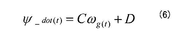
- the recursive least square method it is possible to determine the sensitivity coefficients C and the offset coefficient D.
- the sensitivity coefficient C and the offset coefficient D correspond to the third information of the present invention.
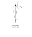
- FIG. 1 is a diagram for explaining a method of calculating a movement distance and a yaw angle change amount using one feature.
- a road sign having a flat plate shape is used as a feature.
- LiDAR is used as an external sensor.
- the vehicle travel distance ⁇ L and the yaw angle change amount ⁇ are calculated by the following procedure. (1) at a point P 1 of the current vehicle, it is measured by LiDAR the distance and direction to a predetermined feature A.
- the moving distance ⁇ L is obtained by using the cosine theorem for triangle composed of feature A and the vehicle position P 1 and the vehicle position P 2. Further, the yaw angle change amount ⁇ is obtained by subtracting ⁇ from ⁇ A2 , and ⁇ is obtained by adding ⁇ A1 and ⁇ . Therefore, using the distances r A1 , r A2 , angles ⁇ A1 , ⁇ A2 , and ⁇ , the movement distance ⁇ L and the yaw angle change amount ⁇ are calculated by the following equations.
- the yaw angle ⁇ can be calculated by integrating the yaw angle change amount ⁇
- the yaw rate ⁇ _dot (t) can be calculated by dividing the yaw angle change quantity ⁇ by the predetermined time ⁇ t.
- the vehicle body speed V can be calculated by dividing the moving distance ⁇ L by the predetermined time ⁇ t
- the moving distance L can also be calculated by integrating the moving distance ⁇ L.
- FIG. 2 is a block diagram illustrating a configuration of the coefficient updating apparatus 10 according to the embodiment.
- the coefficient update device 10 includes a vehicle speed sensor 7, an acceleration sensor 8, a gyro sensor 9, an external sensor (LiDAR) 12, a feature measurement unit 13, a beam angle calculation unit 14, and a coefficient calculation.
- the feature measurement unit 13, the beam angle calculation unit 14, the coefficient calculation unit 15, and the movement distance / yaw angle change amount calculation unit 16 are realized by a computer such as a CPU executing a program prepared in advance. be able to.
- the vehicle speed sensor 7 supplies the wheel rotation speed ⁇ p (t) measured based on the axle rotation pulse to the coefficient calculation unit 15.
- the acceleration sensor 8 detects the acceleration ⁇ ac (t) of the vehicle and supplies it to the coefficient calculation unit 15. Further, the gyro sensor 9 supplies the detected angular velocity ⁇ g (t) to the coefficient calculation unit 15.
- the feature measurement unit 13 measures the distance r to the feature and the angle ⁇ with the feature based on the output of the external sensor 12 and supplies the measured distance to the movement distance / yaw angle change calculation unit 16. In addition, the feature measurement unit 13 converts the distance r and the angle ⁇ into orthogonal coordinates (x, y, z) in which the traveling direction is x, the horizontal direction is y, and the height direction is z. The coordinates are supplied to the beam angle calculation unit 14.
- the beam angle calculation unit 14 is also referred to as an angle ⁇ (hereinafter referred to as “beam angle”) formed by the beam from the external sensor 12 and the normal vector of the planar plate-like feature based on the output of the external sensor 12. ) And is supplied to the movement distance / yaw angle change amount calculation unit 16.
- the movement distance / yaw angle change amount calculation unit 16 uses the distance r to the feature at different times, the angle ⁇ with the feature, and the beam angle ⁇ according to the above formulas (11) and (12).
- the movement distance ⁇ L and the yaw angle change amount ⁇ are calculated and supplied to the coefficient calculation unit 15.
- the coefficient calculation unit 15 first calculates the vehicle body speed V (t) by dividing the movement distance ⁇ L by the predetermined time ⁇ t. Next, the coefficient calculation unit 15 calculates the conversion coefficient K of the vehicle speed sensor 7 according to the equation (1) based on the vehicle body speed V (t) and the wheel rotation speed ⁇ p (t) output from the vehicle speed sensor 7. ,Update. Further, the coefficient calculation unit 15 is based on the vehicle body speed V (t) , the vehicle body speed V (t ⁇ 1) one time before, the time interval ⁇ t, and the acceleration ⁇ ac (t) output from the acceleration sensor 8. The sensitivity coefficient A and the offset B of the acceleration sensor 8 are calculated and updated by the equations (2) to (3).
- the coefficient calculation unit 15 uses the equation (7) based on the angular velocity ⁇ g (t) supplied from the gyro sensor 9 and the yaw angle change amount ⁇ supplied from the movement distance / yaw angle change amount calculation unit 16.
- the sensitivity coefficient C and the offset coefficient D of the gyro sensor are calculated and updated by (8) to (8).
- the feature measurement unit 13 is an example of the first acquisition unit of the present invention
- the beam angle calculation unit 14 includes the second acquisition unit, the first to second direction determination units, and the first to first of the present invention.
- 6 is an example of the first and second midpoint determination units
- the coefficient calculation unit 15 is an example of the first to third correction units of the present invention
- the movement distance / yaw angle change amount calculation unit 16 is the main calculation unit. It is an example of the calculation part of invention.
- the yaw angle change amount corresponds to the change amount in the traveling direction in the present invention.
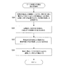
- FIG. 3 is a flowchart of the coefficient update process.
- the coefficient updating apparatus 10 measures one feature A by the external sensor 12, and acquires measurement data including the distance r to the feature and the angle ⁇ with the feature (step S10).
- the coefficient update device 10 calculates the beam angle ⁇ using the measurement data (step S11). The method for calculating the beam angle ⁇ will be described in detail later.
- the coefficient updating apparatus 10 determines whether or not there is measurement data of the feature A one hour before (step S12). When there is no measurement data one hour before (step S12: NO), the coefficient update device 10 increments the time (step S13), and the process returns to step S10.
- step S12 when there is measurement data one hour ago (step S12: YES), the coefficient updating apparatus 10 determines the distance r A1 , angle ⁇ A1 , beam angle ⁇ 1 of the feature A one hour ago, and the ground at the current time. Using the object distance r A2 , the angle ⁇ A2 , and the beam angle ⁇ 2 , the yaw angle change amount ⁇ and the movement distance ⁇ L are calculated from the equations (11) and (12) (step S14).
- the coefficient updating apparatus 10 calculates the measured vehicle body speed V (t) from the movement distance ⁇ L and the time interval ⁇ t, and calculates the true angular velocity (measurement) using the equation (7) from the yaw angle change amount ⁇ and the time interval ⁇ t. Yaw rate) ⁇ _dot (t) is calculated (step S15).
- the coefficient updating device 10 calculates and updates the conversion coefficient K from the obtained measured vehicle body speed V (t) and the output ⁇ p (t) of the vehicle speed sensor according to the equation (1), and the obtained measured vehicle body. From the speed V (t) , the measured vehicle body speed V (t-1) one time ago, the time interval ⁇ t, and the output ⁇ ac (t ) of the acceleration sensor, the sensitivity coefficient A and the offset coefficient B of the acceleration sensor are obtained by the equation The sensitivity coefficient C and the offset coefficient D are calculated from the measured yaw rate ⁇ _dot (t) and the output ⁇ g (t) of the gyro sensor ⁇ g (t) and updated (step S16). .
- the first embodiment is a method for accurately obtaining the beam angle ⁇ .
- FIG. 4B shows a state where a circular road sign is measured by LiDAR as an example of the target feature.
- a plurality of measurement points are formed on a road sign by a plurality of LiDAR beams.
- the beam angle calculation unit 14 acquires measurement values of a plurality of beams that hit the target feature.
- the beam angle calculation unit 14 determines that the measurement point having the reflectance equal to or higher than the predetermined threshold is the measurement point on the road sign. To do. Thereby, the beam angle calculation unit 14 acquires a plurality of measurement points existing on the road sign.
- the white circles in FIG. 4B image a beam that is not detected below the threshold.
- the beam angle calculation unit 14 coordinates (x 1 , y 1 , z 1 ), (x 2 , y 2 , z 2 ), (x 2 , y 2 , z 2 ),.
- the coordinates G (x g , y g , z g ) of the barycentric point are obtained from x n , y n , z n ).
- the beam angle calculation unit 14 uses the coordinates G (x g , y g , z g ) of the centroid point to move the centroid point (x g , y g , Find direction vectors up to z g ).
- the beam angle calculation unit 14 calculates the coordinates (x 1 , y 1 , z 1 ), (x 2 , y 2 , z 2 ), ... (x n , y n , z n ) of each measurement point, By using the method of least squares, a plane expression that defines the surface of the road sign is generated, and a normal vector of the plane is obtained. Then, the beam angle calculation unit 14 obtains a beam angle ⁇ , which is an angle formed by the two vectors, from the plane normal vector and the xy component of the direction vector from the vehicle to the center of gravity.
- the beam angle calculation unit 14 calculates a plane equation from a plurality of measurement points (x k , y k , z k ) existing on the road sign.
- Equation (16) ( ⁇ , ⁇ , ⁇ ) that minimizes Equation (16) is obtained by the method of least squares.
- the ( ⁇ , ⁇ , ⁇ ) that minimizes the equation (16) becomes 0 when the equation (16) is partially differentiated.
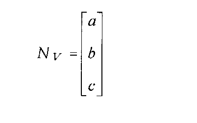
- the normal vector N V or less (see FIG. 6 (A)).
- the direction vector DV is as follows (see FIG. 6B).
- the direction vector DV is as follows (see FIG. 6C).
- the beam angle ⁇ is obtained from the following equation.
- the first embodiment obtains a plane equation by the least square method, as shown in FIG. 7B, the normal vector is obtained even if the feature is somewhat curved. be able to. Further, as shown in FIG. 7C, even if there is some unevenness on the surface of the feature, a plane equation by the least square method can be created, and a normal vector can be obtained.
- FIG. 8 is a flowchart of beam angle calculation processing according to the first embodiment. This process corresponds to step S11 of the coefficient update process shown in FIG.
- the beam angle calculation unit 14 obtains the center of gravity G (x g , y g , z g ) from n pieces of data (x k , y k , z k ) obtained by measuring the feature A with LiDAR.
- the direction vector D V (x g , y g , z g ) from the vehicle to the center of gravity G is calculated.
- the beam angle calculation unit 14 obtains the distance r A [t] and the angle ⁇ A [t] from the vehicle to the center of gravity G (step S21).
- the second embodiment is a method for simply obtaining the beam angle ⁇ .
- FIG. 9 shows a calculation method of the beam angle ⁇ according to the second embodiment.
- the position of the vehicle is the origin O
- both ends of the planar plate-like feature are points C and E.
- the beam angle calculation unit 14 extracts the distance to the end points C and E, that is, the OC length and the OE length, and the angle ⁇ between them from the measurement data of the feature.
- the beam angle calculation unit 14 obtains the CE length by the cosine theorem for the triangle ⁇ OCE as follows.
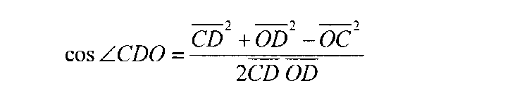
- the beam angle calculation unit 14 obtains the angle of ⁇ OCE using the cosine theorem using the obtained CE length as follows.
- the beam angle calculation unit 14 obtains the angle of the CDO using the obtained OD length.
- the beam angle calculation unit 14 subtracts the angle of the CDO from 90 degrees to obtain the angle ⁇ .
- FIG. 10 is a flowchart of beam angle calculation processing according to the second embodiment. This process corresponds to step S11 of the coefficient update process shown in FIG.
- the beam angle calculation unit 14 selects the two beams that are farthest in the horizontal direction from among the plurality of beams that have detected the feature A, obtains both end points C and E of the feature, and both end points C and E Distances OC, OE and an angle ⁇ therebetween are acquired (step S31).
- the beam angle calculation unit 14 obtains the midpoint D of the end points C and E, and obtains the distance (OD length) from the vehicle to the midpoint D (step S32).
- the beam angle calculation unit 14 obtains an angle ( ⁇ CDO) formed by the straight line OD connecting the vehicle and the midpoint D and the plane of the feature (step S33).
- the beam angle calculation unit 14 subtracts the obtained angle ( ⁇ CDO) from 90 degrees to calculate the angle ⁇ (step S34).
- the calculation process of the beam angle ⁇ ends.
- the third embodiment is a method of approximately obtaining the beam angle ⁇ .
- FIG. 11 shows a calculation method of the beam angle ⁇ according to the third embodiment.
- the position of the vehicle is the origin O
- both ends of the planar plate-like feature are points C and E.
- the beam angle calculation unit 14 first extracts the distance to the end points C and E, that is, the OC length and the OE length, and the angle ⁇ between them from the measurement data of the feature.
- triangle ⁇ OCF is an isosceles triangle
- the straight line OC and the straight line OE can be regarded as substantially parallel. Therefore, when the triangle ⁇ CFE is regarded as a right triangle whose ⁇ CFE is a right angle, the angle ⁇ is obtained as follows.
- FIG. 12 is a flowchart of a beam angle calculation process according to the third embodiment. This process corresponds to step S11 of the coefficient update process shown in FIG.
- the beam angle calculation unit 14 selects the two beams that are farthest in the horizontal direction from the plurality of beams that have detected the feature A, obtains the end points C and E of the feature, and reaches the end points C and E. Distances OC and OE and an angle ⁇ therebetween are acquired (step S41).
- the beam angle calculation unit 14 provides the point F on the straight line OE from the vehicle to the end point E, and calculates the FE length from the point F to the end point E by the above-described equation (29) (step S42).
- the beam angle calculation unit 14 calculates the CF length by the equation (30) using the OC length and the angle ⁇ (step S43). And the beam angle calculation part 14 calculates angle (phi) by Formula (31) using FE length and CF length (step S44). Thus, the calculation process of the beam angle ⁇ ends.
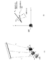
- FIG. 13A shows how the vehicle moves while measuring one feature with LiDAR.
- the vehicle When measuring the left edge of the feature is the vehicle is in the position P 1, when measuring the right edge of a feature is, the vehicle is moving to the position P n.
- FIG. 13B is a diagram in which the coordinates (r, ⁇ ) of points on the feature measured by LiDAR in the example of FIG. 13A are converted into (x, y) coordinates with the vehicle position as the origin. Indicates. As the vehicle moves, the distance and direction to the feature changes, and the plane of the feature becomes distorted. As a result, the center (or centroid) coordinates of the feature and the normal vector are shifted.
- the scan period of the horizontal scan type LiDAR is T [s]
- the speed at which the beam moves is r ⁇ [m / s]. If there is a road sign with a width W [m], the time ⁇ T for scanning the road sign is as follows.
- the road sign measurement time estimated in the above consideration is about several ms, it can be considered that there is almost no change in vehicle speed or yaw rate within that time. Therefore, using the vehicle speed and yaw rate values calculated at the previous time, calculate the direction change and position change of the vehicle during the current feature measurement, and use the changes to measure each measurement point. What is necessary is just to obtain
- the feature coordinates measured by P k points converted into values using a coordinate system P 1 point.
- coordinates are rotated to a coordinate axis indicated by a broken line at a point P k , and then a difference ( ⁇ x k , ⁇ y k ) between positions in the x direction and the y direction is added.
- ⁇ x k and ⁇ y k can be expressed as follows.
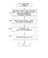
- FIG. 15 is a flowchart of the coordinate calculation processing of the measurement points of the feature in consideration of the movement of the vehicle within the feature measurement time. This process is performed by the above-described feature measuring unit 13.
- the feature measuring unit 13 reads the vehicle speed V (t-1) and yaw rate ⁇ _dot (t-1) measured (or estimated) at the previous time (step S50), and has a planar road sign.
- the measurement data of n points for the feature A as a target is acquired (step S51).
- feature measuring unit 13 sets the data P 1 at the left end of the measurement data of the feature in the position and orientation of the reference (step S52).
- the feature measuring unit 13 sets “1” to the coefficient k (step S53), and determines whether the coefficient k is equal to or less than the number of measurement data n (step S54). If the coefficient k is less than or equal to the measurement data number n (step S54: YES), feature measuring unit 13 obtains the time difference Delta] t k from point P 1 to the point P k (step S55).
- the feature measuring unit 13 obtains an angle change ⁇ k from the point P 1 to the point P k using the above-described equation (33) (step S56), and further calculates equations (34) and (35). Using this, the difference ( ⁇ x k , ⁇ y k ) between the points P 1 and P k is obtained (step S57). Then, the feature measuring unit 13 calculates the coordinates of the feature at the point P k in the coordinate system with reference to the point P 1 using the equation (36) (step S58).
- the feature measuring unit 13 increments the coefficient k (step S59) and returns to step S54. Then, when the coefficient k exceeds the number of measurement data n (step S54: NO), the process ends.
- the yaw angle ⁇ can be calculated by integrating the yaw angle change amount ⁇
- the yaw rate ⁇ _dot (t) can be calculated by dividing the yaw angle change quantity ⁇ by the predetermined time ⁇ t.
- the vehicle body speed V can be calculated by dividing the moving distance ⁇ L by the predetermined time ⁇ t
- the moving distance L can also be calculated by integrating the moving distance ⁇ L.
- the present invention can be used for an apparatus mounted on a moving body.
Landscapes
- Engineering & Computer Science (AREA)
- Physics & Mathematics (AREA)
- Automation & Control Theory (AREA)
- Mathematical Physics (AREA)
- Transportation (AREA)
- Mechanical Engineering (AREA)
- General Physics & Mathematics (AREA)
- Radar, Positioning & Navigation (AREA)
- Remote Sensing (AREA)
- Measurement Of Distances Traversed On The Ground (AREA)
- Navigation (AREA)
Abstract
測定装置は、第1時刻及び第2時刻それぞれにおける、移動体から1の地物上の少なくとも2つの位置までのそれぞれの距離及び前記移動体からみた前記地物の方向と前記移動体の進行方向とがなす角度をそれぞれ取得し、その取得結果に基づき、前記第1時刻から前記第2時刻までの前記移動体の移動距離と進行方向の変化量を算出する。
Description
本発明は、移動体の進行方向の変化を検出する技術に関する。
移動体の前方に存在する物体を認識して、移動体のヨーレートを補正する手法が知られている。特許文献1は、移動体の前方に存在する固定物を認識し、その固定物が自車両に対して相対的に移動する移動軌跡に基づいて、ヨーレートセンサのずれ量を補正する手法を記載している。
特許文献1に記載の手法では、上記の移動軌跡の他に、車速、旋回半径からのずれ量、固定物が横方向に相対的に移動する横移動量など、推定ヨーレートの算出に用いるパラメータが多く、これらのパラメータを取得するセンサのずれ量も考慮しなくてはならない。
本発明が解決しようとする課題としては、上記のものが例として挙げられる。本発明は、1つのセンサで移動体の移動量とヨー角を算出し、移動距離と進行方向の変化量を得ることが可能な測定装置を提供することを目的とする。
請求項1に記載の発明は、測定装置であって、第1時刻及び第2時刻それぞれにおける、移動体から1の地物上の少なくとも2つの位置までのそれぞれの距離及び前記移動体からみた前記地物の方向と前記移動体の進行方向とがなす角度をそれぞれ取得する第1取得部と、前記第1取得部の取得結果に基づき、前記第1時刻から前記第2時刻までの前記移動体の移動距離及び前記移動体の進行方向の変化量のうち少なくとも一方を算出する算出部と、を備えることを特徴とする。
請求項10に記載の発明は、測定装置により実行される測定方法であって、第1時刻及び第2時刻それぞれにおける、移動体から1の地物上の少なくとも2つの位置までのそれぞれの距離及び前記移動体からみた前記地物の方向と前記移動体の進行方向とがなす角度をそれぞれ取得する第1取得工程と、前記第1取得部の取得結果に基づき、前記第1時刻から前記第2時刻までの前記移動体の移動距離及び前記移動体の進行方向の変化量のうち少なくとも一方を算出する算出工程と、を備えることを特徴とする。
請求項11に記載の発明は、コンピュータを備える測定装置によって実行されるプログラムであって、第1時刻及び第2時刻それぞれにおける、移動体から1の地物上の少なくとも2つの位置までのそれぞれの距離及び前記移動体からみた前記地物の方向と前記移動体の進行方向とがなす角度をそれぞれ取得する第1取得部、前記第1取得部の取得結果に基づき、前記第1時刻から前記第2時刻までの前記移動体の移動距離及び前記移動体の進行方向の変化量のうち少なくとも一方を算出する算出部、として前記コンピュータを機能させることを特徴とする。
本発明の好適な実施形態では、測定装置は、第1時刻及び第2時刻それぞれにおける、移動体から1の地物上の少なくとも2つの位置までのそれぞれの距離及び前記移動体からみた前記地物の方向と前記移動体の進行方向とがなす角度をそれぞれ取得する第1取得部と、前記第1取得部の取得結果に基づき、前記第1時刻から前記第2時刻までの前記移動体の移動距離及び前記移動体の進行方向の変化量のうち少なくとも一方を算出する算出部と、を備える。
上記の測定装置は、第1時刻及び第2時刻それぞれにおける、移動体から1の地物上の少なくとも2つの位置までのそれぞれの距離及び前記移動体からみた前記地物の方向と前記移動体の進行方向とがなす角度をそれぞれ取得し、その取得結果に基づき、前記第1時刻から前記第2時刻までの前記移動体の移動距離及び前記移動体の進行方向の変化量のうち少なくとも一方を算出する。これにより、移動体から計測できる任意の地物を利用して、移動体の移動距離及び移動体の進行方向の変化量のうち少なくとも一方を算出することができる。
上記の測定装置の一態様は、前記少なくとも2つの位置の座標を取得する第2取得部を更に備え、前記算出部は、前記第1時刻及び前記第2時刻における、(i)前記移動体から前記少なくとも2つの位置までのそれぞれの距離及び前記少なくとも2つの位置の座標に基づいて算出される、前記地物の表面に対する法線と前記移動体からみた前記地物上の1つの位置の方向とがなす角度、並びに(ii)前記移動体からみた前記1つの位置の方向と前記移動体の進行方向とがなす角度、に基づき前記移動距離及び前記変化量のうち少なくとも一方を算出する。
上記の測定装置の他の一態様では、前記第1取得部は、前記移動体から前記1の地物の少なくとも3つの位置までの距離及び前記移動体から見た前記少なくとも3つの位置の方向から、前記少なくとも3つの位置の座標を計算する第1計算部と、前記少なくとも3つの位置の座標に基づいて前記地物の表面の重心点の座標を計算し、前記移動体からみた前記重心点の方向を決定する第1方向決定部と、前記少なくとも3つの位置の座標に基づいて前記地物の表面を規定する平面の式を計算し、前記平面の式に基づいて前記地物の表面に対する法線の方向を決定する第2方向決定部と、前記重心点の方向と前記法線の方向とのなす角度を計算する第2計算部と、を備え、前記算出部は、前記第1時刻及び第2時刻それぞれにおける、前記移動体から前記重心点までの距離、前記移動体からみた前記重心点の方向と前記移動体の進行方向とがなす角度、及び、前記重心点の方向と前記法線の方向とのなす角度に基づいて、前記移動距離及び前記変化量のうち少なくとも一方を算出する。
上記の測定装置の他の一態様では、前記第1取得部は、前記移動体から前記1の地物の両端点までの距離、及び、前記移動体からみた前記両端点それぞれの方向がなす角度を計算する第3計算部と、前記両端点までの距離、及び、前記移動体からみた前記両端点それぞれの方向がなす角に基づいて、前記1の地物の中点の座標を決定する第1中点決定部と、前記移動体からみた前記中点の方向と、前記中点における前記地物の表面に対する法線の方向とがなす角度を計算する第4計算部と、を備え、前記算出部は、前記第1時刻及び第2時刻それぞれにおける、前記移動体から前記中点までの距離、前記移動体からみた前記中点の方向と前記移動体の進行方向とがなす角度、及び、前記中点の方向と前記法線の方向とがなす角度に基づいて、前記移動距離及び前記変化量のうち少なくとも一方を算出する。
上記の測定装置の他の一態様では、前記第1取得部は、前記移動体から前記1の地物の両端点までの距離、及び、前記移動体からみた前記両端点それぞれの方向のなす角度を計算する第5計算部と、前記両端点までの距離、及び、前記移動体からみた前記両端点それぞれの方向がなす角に基づいて、前記1の地物の中点の座標を決定する第2中点決定部と、前記移動体からみた前記両端点それぞれの方向が平行であるとみなして、前記移動体からみた前記中点の方向と、前記中点における前記地物の表面に対する法線の方向とがなす角度を計算する第6計算部と、を備え、前記算出部は、前記第1時刻及び第2時刻それぞれにおける、前記移動体から前記中点までの距離、前記移動体からみた前記中点の方向と前記移動体の進行方向とがなす角度、及び、前記中点の方向と前記法線の方向とがなす角度に基づいて、前記移動距離及び前記変化量のうち少なくとも一方を算出する。
上記の測定装置の他の一態様は、前記地物上の複数の位置のうちの1つを計測したときの前記移動体の位置である移動体位置を基準位置とし、前記複数の位置のうち前記基準位置以外の前記移動体位置で計測した位置の座標を、前記基準位置の座標系における座標に変換する座標変換部を備える。この態様では、地物を計測している時間内における移動体の移動を考慮して位置座標を補正することにより、移動体の進行方向の変化量を高精度で算出することができる。
上記の測定装置の他の一態様では、前記算出部は前記移動距離を算出し、前記測定装置は、前記移動距離に基づき算出される、単位時間あたりの移動距離に基づき、前記移動体に搭載される車速センサの前記第2時刻における出力結果から前記移動体の速度を算出するための第1情報を補正する第1補正部を更に備える。この態様では、算出される移動距離に基づいて、移動体の車速センサを適切に補正することができる。
上記の測定装置の他の一態様では、前記算出部は前記移動距離を算出し、前記測定装置は、前記移動距離に基づき算出される、単位時間あたりの移動距離に基づき、前記移動体に搭載される加速度センサの前記第2時刻における出力結果から前記移動体の速度を算出するための第2情報を補正する第2補正部を更に備える。この態様では、算出される移動距離に基づいて、移動体の加速度センサを適切に補正することができる。
上記の測定装置の他の一態様では、前記算出部は前記変化量を算出し、前記測定装置は、前記変化量に基づき算出される、単位時間あたりの前記進行方向の変化量に基づき、前記移動体に搭載される角速度センサの前記第2時刻における出力結果から前記移動体のヨーレートを算出するための第3情報を補正する第3補正部を更に備える。この態様では、算出される進行方向の変化量に基づいて、移動体の角速度センサを適切に補正することができる。
本発明の他の好適な実施形態は、測定装置により実行される測定方法であって、第1時刻及び第2時刻それぞれにおける、移動体から1の地物上の少なくとも2つの位置までのそれぞれの距離及び前記移動体からみた前記地物の方向と前記移動体の進行方向とがなす角度をそれぞれ取得する第1取得工程と、前記第1取得部の取得結果に基づき、前記第1時刻から前記第2時刻までの前記移動体の移動距離及び前記移動体の進行方向の変化量のうち少なくとも一方を算出する算出工程と、を備える。これにより、移動体から計測できる任意の地物を利用して、移動体の移動距離及び移動体の進行方向の変化量のうち少なくとも一方を算出することができる。
本発明の他の好適な実施形態では、コンピュータを備える測定装置によって実行されるプログラムは、第1時刻及び第2時刻それぞれにおける、移動体から1の地物上の少なくとも2つの位置までのそれぞれの距離及び前記移動体からみた前記地物の方向と前記移動体の進行方向とがなす角度をそれぞれ取得する第1取得部、前記第1取得部の取得結果に基づき、前記第1時刻から前記第2時刻までの前記移動体の移動距離及び前記移動体の進行方向の変化量のうち少なくとも一方を算出する算出部、として前記コンピュータを機能させる。これにより、移動体から計測できる任意の地物を利用して、移動体の移動距離及び移動体の進行方向の変化量のうち少なくとも一方を算出することができる。このプログラムは、記憶媒体に記憶して利用することができる。
以下、図面を参照して本発明の好適な実施例について説明する。
[1]背景
従来のカーナビゲーション装置に搭載されている自車位置推定システムでは、車速センサから算出される速度や加速度センサの出力から算出される速度と、ジャイロセンサの出力から算出されるヨー角とを用いて車両の移動状態を測定し、GPS情報と統合することにより現在位置を推定する複合航法システムが用いられている。複合航法システムによる自車位置推定精度向上のためには、車体速度とヨー角を正確に把握する必要がある。
従来のカーナビゲーション装置に搭載されている自車位置推定システムでは、車速センサから算出される速度や加速度センサの出力から算出される速度と、ジャイロセンサの出力から算出されるヨー角とを用いて車両の移動状態を測定し、GPS情報と統合することにより現在位置を推定する複合航法システムが用いられている。複合航法システムによる自車位置推定精度向上のためには、車体速度とヨー角を正確に把握する必要がある。
車両の車体速度は、車速センサから出力される車軸回転パルスに基づく車輪回転速度に変換係数を乗算することにより得られる。また、車体速度は、加速度センサから出力される検出加速度と、加速度センサの感度係数及びオフセット係数とに基づいて算出することができる。さらに、車両のヨー角は、ジャイロセンサから出力される角速度と、ジャイロセンサの感度係数及びオフセット係数とに基づいて算出することができる。
一般的に、車速センサの変換係数、加速度センサの感度とオフセット、及び、ジャイロセンサの感度とオフセットは、温度や振動などによって変化する特性がある。そのため、それらの誤差を含んだ状態で車体速度やヨー角を算出すると、誤差が蓄積し、計算される車体速度やヨー角は実際の値から大きくずれてしまう。従って、車体速度やヨー角を高精度に推定するためには、車速センサの変換係数、加速度センサの感度とオフセット、ジャイロセンサの感度とオフセットを継続的に補正することが必要である。
従来のカーナビゲーション装置では、GPS情報に基づくドップラー速度を用いて車速センサ出力から車体速度を求める変換係数や加速度センサの感度とオフセットの補正を行っており、GPS情報の方位変化量を用いてジャイロセンサの感度とオフセットの補正を行っている。そのため、都市部のようなGPSの受信状態の悪い環境では補正の精度が劣化する。また、トンネルや地下駐車場のようなGPS測位ができない環境では補正ができない。よって、GPSの受信状態に関わらず、継続的に変換係数や感度とオフセットの補正を行うことが要求される。
本実施例による係数更新装置は、GPS情報を用いずに、外界センサによる1つの地物の計測結果に基づいて車両の移動距離とヨー角変化量を算出し、車速センサから車体速度を求めるための変換係数、加速度センサの感度とオフセット、及び、ジャイロセンサの感度とオフセットを補正する。また、係数更新装置は移動距離を所定時間で除算することにより車体速度Vを算出することができる。なお、外界センサとしては、LiDAR(Light Detection And Ranging)が挙げられる。
[2]係数の推定方法
[2.1]車速センサから車体速度を求めるための変換係数の推定方法
真の車体速度V(t)と、車速センサから出力される車軸回転パルスに基づく車輪回転速度ωp(t)との関係は、変換係数Kを用いて次のように表すことができる。
[2.1]車速センサから車体速度を求めるための変換係数の推定方法
真の車体速度V(t)と、車速センサから出力される車軸回転パルスに基づく車輪回転速度ωp(t)との関係は、変換係数Kを用いて次のように表すことができる。

[2.2]加速度センサの感度係数とオフセット係数の推定方法
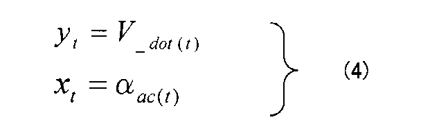
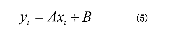
真の車体加速度V_dot(t)と、加速度センサで検出する加速度αac(t)との関係は、感度係数Aとオフセット係数Bを用いて次のように表すことができる。
真の車体加速度V_dot(t)と、加速度センサで検出する加速度αac(t)との関係は、感度係数Aとオフセット係数Bを用いて次のように表すことができる。


[2.3]ジャイロセンサの感度係数とオフセット係数の推定方法
真の角速度Ψ_dot(t)と、ジャイロセンサで検出する角速度ωg(t)との関係は、感度係数Cとオフセット係数Dを用いて次のように表すことができる。
真の角速度Ψ_dot(t)と、ジャイロセンサで検出する角速度ωg(t)との関係は、感度係数Cとオフセット係数Dを用いて次のように表すことができる。



[3]移動距離とヨー角変化量の算出方法
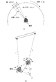
以下、外界センサを用いて車両の移動距離ΔLとヨー角変化量ΔΨを求める方法を説明する。図1は、1つの地物を用いて移動距離とヨー角変化量を算出する方法を説明する図である。なお、前提として、平面板状である道路標識を地物として利用するものとする。また、外界センサとしてLiDARを用いるものとする。以下の手順により、車両の移動距離ΔLとヨー角変化量ΔΨを算出する。
(1)現在の車両の地点P1において、所定の地物Aまでの距離と方向をLiDARにより計測する。
(2)地物を検出した複数のビームから、地物の重心点又は中点の座標を求め、車両から地物までの距離rA1と角度θA1を求める。
(3)地物が平面板状であることを前提に、地物の法線ベクトルと、LiDARのビームとの角度φ1を算出する。
(4)所定時間Δt経過後、地点P2において上記(1)~(3)の処理を行い、距離rA2、角度θA2、角度φ2を算出する。
(5)下記の式により角度φ2とφ1の差分Δφを求める。
以下、外界センサを用いて車両の移動距離ΔLとヨー角変化量ΔΨを求める方法を説明する。図1は、1つの地物を用いて移動距離とヨー角変化量を算出する方法を説明する図である。なお、前提として、平面板状である道路標識を地物として利用するものとする。また、外界センサとしてLiDARを用いるものとする。以下の手順により、車両の移動距離ΔLとヨー角変化量ΔΨを算出する。
(1)現在の車両の地点P1において、所定の地物Aまでの距離と方向をLiDARにより計測する。
(2)地物を検出した複数のビームから、地物の重心点又は中点の座標を求め、車両から地物までの距離rA1と角度θA1を求める。
(3)地物が平面板状であることを前提に、地物の法線ベクトルと、LiDARのビームとの角度φ1を算出する。
(4)所定時間Δt経過後、地点P2において上記(1)~(3)の処理を行い、距離rA2、角度θA2、角度φ2を算出する。
(5)下記の式により角度φ2とφ1の差分Δφを求める。


[4]係数更新装置
次に、上記のようにして算出された移動距離ΔL及びヨー角変化量ΔΨを用いて、車速センサの変換係数K、加速度センサの感度係数A及びオフセットB、ジャイロセンサの感度係数C及びオフセット係数Dを更新する係数更新装置について説明する。図2は、実施例による係数更新装置10の構成を示すブロック図である。図示のように、係数更新装置10は、車速センサ7と、加速度センサ8と、ジャイロセンサ9と、外界センサ(LiDAR)12と、地物計測部13と、ビーム角度算出部14と、係数計算部15と、移動距離・ヨー角変化量計算部16とを備える。なお、地物計測部13、ビーム角度算出部14、係数計算部15、及び、移動距離・ヨー角変化量計算部16は、CPUなどのコンピュータが予め用意されたプログラムを実行することにより実現することができる。
次に、上記のようにして算出された移動距離ΔL及びヨー角変化量ΔΨを用いて、車速センサの変換係数K、加速度センサの感度係数A及びオフセットB、ジャイロセンサの感度係数C及びオフセット係数Dを更新する係数更新装置について説明する。図2は、実施例による係数更新装置10の構成を示すブロック図である。図示のように、係数更新装置10は、車速センサ7と、加速度センサ8と、ジャイロセンサ9と、外界センサ(LiDAR)12と、地物計測部13と、ビーム角度算出部14と、係数計算部15と、移動距離・ヨー角変化量計算部16とを備える。なお、地物計測部13、ビーム角度算出部14、係数計算部15、及び、移動距離・ヨー角変化量計算部16は、CPUなどのコンピュータが予め用意されたプログラムを実行することにより実現することができる。
車速センサ7は、車軸回転パルスに基づき計測される車輪回転速度ωp(t)を係数計算部15へ供給する。加速度センサ8は、車両の加速度αac(t)を検出し、係数計算部15へ供給する。また、ジャイロセンサ9は、検出した角速度ωg(t)を係数計算部15へ供給する。
地物計測部13は、外界センサ12の出力に基づいて地物までの距離r及び地物との角度θを計測して移動距離・ヨー角変化量計算部16へ供給する。また、地物計測部13は、距離rと角度θを、進行方向をx、横方向をy、高さ方向をzとする直交座標(x,y,z)に変換し、各計測点の座標としてビーム角度算出部14へ供給する。
ビーム角度算出部14は、外界センサ12の出力に基づいて、外界センサ12からのビームと、平面板状である地物の法線ベクトルとのなす角度φ(以下、「ビーム角度」とも呼ぶ。)を算出し、移動距離・ヨー角変化量計算部16へ供給する。移動距離・ヨー角変化量計算部16は、異なる時刻における地物までの距離rと、地物との角度θと、ビーム角度φとを用いて、前述の式(11)、(12)により、移動距離ΔL及びヨー角変化量ΔΨを算出し、係数計算部15へ供給する。
係数計算部15は、まず、移動距離ΔLを所定時間Δtで除算して車体速度V(t)を算出する。次に、係数計算部15は、車体速度V(t)と車速センサ7から出力された車輪回転速度ωp(t)に基づいて、式(1)により車速センサ7の変換係数Kを算出し、更新する。また、係数計算部15は、車体速度V(t)と1時刻前の車体速度V(t-1)と時間間隔Δtと、加速度センサ8から出力された加速度αac(t)に基づいて、式(2)~(3)により加速度センサ8の感度係数A及びオフセットBを算出し、更新する。さらに、係数計算部15は、ジャイロセンサ9から供給された角速度ωg(t)と、移動距離・ヨー角変化量計算部16から供給されたヨー角変化量ΔΨに基づいて、式(7)~(8)によりジャイロセンサの感度係数C及びオフセット係数Dを算出し、更新する。
上記の構成において、地物計測部13は本発明の第1取得部の一例であり、ビーム角度算出部14は本発明の第2取得部、第1~第2方向決定部、第1~第6計算部、第1~第2中点決定部の一例であり、係数計算部15は本発明の第1~第3補正部の一例であり、移動距離・ヨー角変化量計算部16は本発明の算出部の一例である。また、ヨー角変化量は本発明における進行方向の変化量に相当する。
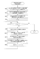
次に、上記の係数更新装置10による係数更新処理について説明する。図3は、係数更新処理のフローチャートである。まず、係数更新装置10は、外界センサ12により1つの地物Aを計測し、地物との距離r及び地物との角度θを含む計測データを取得する(ステップS10)。次に、係数更新装置10は、それら計測データを用いて、ビーム角度φを算出する(ステップS11)。なお、ビーム角度φの算出方法については後に詳しく説明する。
次に、係数更新装置10は、地物Aの1時刻前の計測データがあるか否かを判定する(ステップS12)。1時刻前の計測データが無い場合(ステップS12:NO)、係数更新装置10は時刻をインクリメントし(ステップS13)、処理はステップS10へ戻る。
一方、1時刻前の計測データがある場合(ステップS12:YES)、係数更新装置10は、1時刻前の地物Aの距離rA1、角度θA1、ビーム角度φ1と、現在時刻の地物の距離rA2、角度θA2、ビーム角度φ2を用いて、式(11)、(12)によりヨー角変化量ΔΨ及び移動距離ΔLを算出する(ステップS14)。そして、係数更新装置10は、移動距離ΔLと時間間隔Δtから計測車体速度V(t)を算出し、ヨー角変化量ΔΨと時間間隔Δtから、式(7)を用いて真の角速度(計測ヨーレート)Ψ_dot(t)を算出する(ステップS15)。
次に、係数更新装置10は、得られた計測車体速度V(t)と車速センサの出力ωp(t)から式(1)により変換係数Kを算出して更新し、得られた計測車体速度V(t)と1時刻前の計測車体速度V(t-1)と時間間隔Δtと加速度センサの出力αac(t)から式(2)により加速度センサの感度係数Aとオフセット係数Bを算出して更新し、さらに得られた計測ヨーレートΨ_dot(t)とジャイロセンサの出力ωg(t)から式(8)により感度係数Cとオフセット係数Dを算出して更新する(ステップS16)。
[5]ビーム角度の算出方法
次に、上記のビーム角度φの算出方法について詳しく説明する。
次に、上記のビーム角度φの算出方法について詳しく説明する。
[5.1]第1実施例
まず、ビーム角度φの算出方法の第1実施例を説明する。第1実施例は、ビーム角度φを正確に求める方法である。
まず、ビーム角度φの算出方法の第1実施例を説明する。第1実施例は、ビーム角度φを正確に求める方法である。
[5.1.1]概要説明
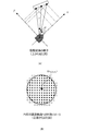
LiDARによる計測によって、車両位置から地物までの距離rと、水平角度θと、垂直角度とが得られる。係数更新装置10のビーム角度算出部14は、図4(A)に示すように、LiDARにより得られる距離と角度データを、車両の進行方向をx、横方向をy、高さ方向をzとする直交座標(x,y,z)に変換する。
LiDARによる計測によって、車両位置から地物までの距離rと、水平角度θと、垂直角度とが得られる。係数更新装置10のビーム角度算出部14は、図4(A)に示すように、LiDARにより得られる距離と角度データを、車両の進行方向をx、横方向をy、高さ方向をzとする直交座標(x,y,z)に変換する。
図4(B)は、対象となる地物の例として、円形の道路標識をLiDARにより計測した様子を示す。LiDARの複数のビームにより、道路標識上に複数の計測点が形成される。ビーム角度算出部14は、対象とする地物に当たった複数のビームの計測値を取得する。このとき、地物の縁にかかるビームは反射率が低くなるため検出されないので、ビーム角度算出部14は、所定の閾値以上の反射率を有する計測点を道路標識上の計測点であると判定する。これにより、ビーム角度算出部14は、道路標識上に存在する複数の計測点を取得する。図4(B)の白抜きの丸は、閾値以下で検出されなかったビームをイメージしている。
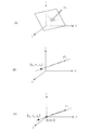
次に、ビーム角度算出部14は、図4(B)に示すように、各計測点の座標(x1,y1,z1)、(x2,y2,z2)、・・(xn,yn,zn)から、重心点の座標G(xg,yg,zg)を求める。次に、図5に示すように、ビーム角度算出部14は、重心点の座標G(xg,yg,zg)を用いて、車両(原点)から重心点(xg,yg,zg)までの方向ベクトルを求める。また、ビーム角度算出部14は、各計測点の座標(x1,y1,z1)、(x2,y2,z2)、・・(xn,yn,zn)から、最小2乗法により、道路標識の表面を規定する平面の式を生成し、その平面の法線ベクトルを求める。そして、ビーム角度算出部14は、平面の法線ベクトル及び車両から重心点までの方向ベクトルのxy成分から、2つのベクトルのなす角度であるビーム角度φを求める。
[5.1.2]詳細説明
次に、上記の算出方法を詳しく説明する。まず、円形の道路標識を含む平面の方程式の求め方を説明する。具体的に、ビーム角度算出部14は、道路標識上に存在する複数の計測点(xk,yk,zk)から、平面の方程式
次に、上記の算出方法を詳しく説明する。まず、円形の道路標識を含む平面の方程式の求め方を説明する。具体的に、ビーム角度算出部14は、道路標識上に存在する複数の計測点(xk,yk,zk)から、平面の方程式


式(15)に(xk,yk)を代入して計算する右辺の値と、zkの値の誤差の総和eは以下の式となる。

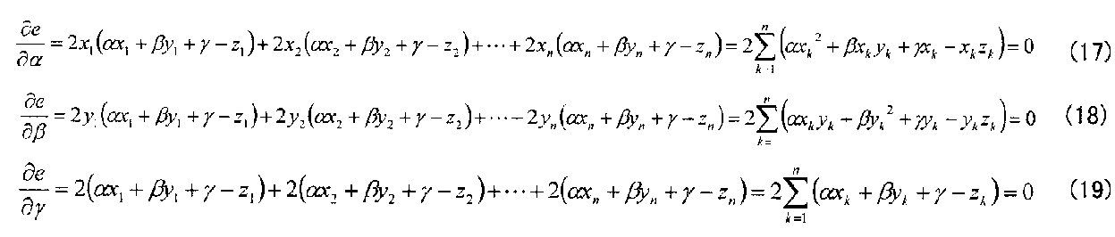




式(22)を式(14)に代入すると、


これを式(22)に代入するとa,b,dが求まり、最終的に以下の結果を得る。


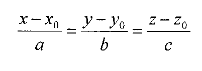


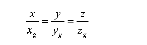


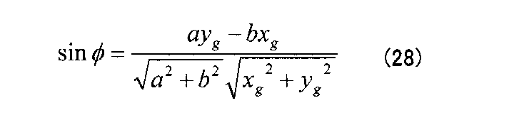
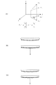
上記のように、第1実施例は、最小2乗法で平面の方程式を求めているため、図7(B)に示すように、地物が多少曲面形状であったとしても法線ベクトルを求めることができる。さらに、図7(C)に示すように、地物の面に多少の凹凸があったとしても、最小2乗法による平面の方程式を作成することができ、法線ベクトルを求めることができる。
[5.1.3]算出処理
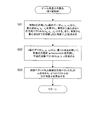
次に、ビーム角度φの算出処理について説明する。図8は、第1実施例によるビーム角度の算出処理のフローチャートである。なお、この処理は、図3に示す係数更新処理のステップS11に相当する。
次に、ビーム角度φの算出処理について説明する。図8は、第1実施例によるビーム角度の算出処理のフローチャートである。なお、この処理は、図3に示す係数更新処理のステップS11に相当する。
まず、ビーム角度算出部14は、LiDARにより地物Aを計測して得たn個のデータ(xk,yk,zk)から、重心点G(xg,yg,zg)を算出し、車両から重心点Gへの方向ベクトルDV(xg,yg,zg)とする。また、ビーム角度算出部14は、車両から重心点Gまでの距離rA[t]と角度θA[t]を求める(ステップS21)。
次に、ビーム角度算出部14は、n個のデータ(xk,yk,zk)から、最小2乗法を用いて、平面の方程式ax+by+cz+d=0を作成し、平面の法線ベクトルNV(a,b,c)を求める(ステップS22)。そして、ビーム角度算出部14は、法線ベクトルNVと方向ベクトルDVのxy成分から、2つのベクトルがなす角度φを算出する(ステップS23)。以上でビーム角度φの算出処理は終了する。
[5.2]第2実施例
次に、ビーム角度φの算出方法の第2実施例を説明する。第2実施例は、ビーム角度φを簡易的に求める方法である。
次に、ビーム角度φの算出方法の第2実施例を説明する。第2実施例は、ビーム角度φを簡易的に求める方法である。
[5.2.1]算出方法
図9は、第2実施例によるビーム角度φの算出方法を示す。図9において、車両の位置を原点Oとし、平面板状の地物の両端が点C、Eであるとする。ビーム角度算出部14は、まず、地物の計測データから、その両端点C、Eまでの距離、即ち、OC長、OE長と、その間の角度Δθを抽出する。
図9は、第2実施例によるビーム角度φの算出方法を示す。図9において、車両の位置を原点Oとし、平面板状の地物の両端が点C、Eであるとする。ビーム角度算出部14は、まず、地物の計測データから、その両端点C、Eまでの距離、即ち、OC長、OE長と、その間の角度Δθを抽出する。
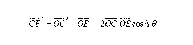
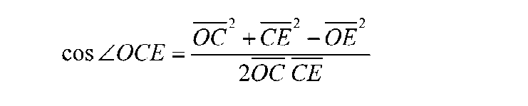
次に、ビーム角度算出部14は、三角形△OCEに対する余弦定理により、下記のようにCE長を求める。


[5.2.2]算出処理
次に、ビーム角度φの算出処理について説明する。図10は、第2実施例によるビーム角度の算出処理のフローチャートである。なお、この処理は、図3に示す係数更新処理のステップS11に相当する。
まず、ビーム角度算出部14は、地物Aを検出した複数のビームのうち、横方向に最も離れた2つのビームを選択して地物の両端点C、Eを求め、両端点C、Eまでの距離OC、OE及びその間の角度Δθを取得する(ステップS31)。次に、ビーム角度算出部14は、両端点C、Eの中点Dを求め、車両からその中点Dまでの距離(OD長)求める(ステップS32)。次に、ビーム角度算出部14は、車両と中点Dとを結んだ直線ODと地物の平面とがなす角度(∠CDO)を求める(ステップS33)。そして、ビーム角度算出部14は、求めた角度(∠CDO)を90度から減算して角度φを算出する(ステップS34)。以上でビーム角度φの算出処理は終了する。
[5.3]第3実施例
次に、ビーム角度φの算出方法の第3実施例を説明する。第3実施例は、ビーム角度φを近似的に求める方法である。
次に、ビーム角度φの算出方法の第3実施例を説明する。第3実施例は、ビーム角度φを近似的に求める方法である。
[5.3.1]算出方法
図11は、第3実施例によるビーム角度φの算出方法を示す。図11において、車両の位置を原点Oとし、平面板状の地物の両端が点C、Eであるとする。ビーム角度算出部14は、まず地物の計測データから、その両端点C、Eまでの距離、即ち、OC長、OE長と、その間の角度Δθを抽出する。
図11は、第3実施例によるビーム角度φの算出方法を示す。図11において、車両の位置を原点Oとし、平面板状の地物の両端が点C、Eであるとする。ビーム角度算出部14は、まず地物の計測データから、その両端点C、Eまでの距離、即ち、OC長、OE長と、その間の角度Δθを抽出する。
次に、直線OE上に、OC長と同じ長さとなる点Fを設けると、

また、三角形△OCFは二等辺三角形であるので、

ここで、車両から地物までの距離が数メートル以上であれば、直線OCと直線OEはほぼ平行とみなすことができる。よって、三角形△CFEを、∠CFEが直角である直角三角形とみなすと、角度φは以下のように得られる。

[5.3.2]算出処理
次に、ビーム角度φの算出処理について説明する。図12は、第3実施例によるビーム角度の算出処理のフローチャートである。なお、この処理は、図3に示す係数更新処理のステップS11に相当する。
まず、ビーム角度算出部14は、地物Aを検出した複数のビームのうち横方向に最も離れた2つのビームを選択して地物の両端点C、Eを求め、両端点C、Eまでの距離OC、OE及びその間の角度Δθを取得する(ステップS41)。次に、ビーム角度算出部14は、車両から端点Eまでの直線OE上に点Fを設け、前述の式(29)により点Fから端点EまでのFE長を算出する(ステップS42)。
次に、ビーム角度算出部14は、OC長と角度Δθを用いて、式(30)によりCF長を算出する(ステップS43)。そして、ビーム角度算出部14は、FE長とCF長を用いて、式(31)により角度φを算出する(ステップS44)。以上でビーム角度φの算出処理は終了する。
[6]地物計測中の車両の移動を考慮した地物の計測点の座標計算
上述したヨー角変化量ΔΨの算出は、地物の法線ベクトルと車両から地物までの方向ベクトルとがなす角度φを求めることにより行われる。しかし、水平方向にスキャンするタイプのLiDARの場合、対象とする地物の左端と右端を計測する時刻が異なるので、その時間内に車両自身が移動すると、計測の基準位置と基準方位が異なることになる。よって、計測の基準位置と基準方位を合わせないままでは、角度φの算出に含まれる誤差が大きくなってしまう。
上述したヨー角変化量ΔΨの算出は、地物の法線ベクトルと車両から地物までの方向ベクトルとがなす角度φを求めることにより行われる。しかし、水平方向にスキャンするタイプのLiDARの場合、対象とする地物の左端と右端を計測する時刻が異なるので、その時間内に車両自身が移動すると、計測の基準位置と基準方位が異なることになる。よって、計測の基準位置と基準方位を合わせないままでは、角度φの算出に含まれる誤差が大きくなってしまう。
図13(A)は、LiDARにより1つの地物を計測する間に車両が移動する様子を示す。地物の左端を計測するときには車両は位置P1にあり、地物の右端を計測するときには車両は位置Pnに移動している。
図13(B)は、図13(A)の例においてLiDARで計測した地物上の点の座標(r、θ)を、車両の位置を原点とした(x,y)座標に変換したものを示す。車両の移動に伴って、地物までの距離と方向が変化するため、地物の平面が歪んだものとなってしまう。その結果、地物の中心(又は重心)座標と法線ベクトルとがずれてしまう。
図14(A)に示すように、水平スキャン型のLiDARのスキャン周期がT[s]の場合、スキャン角周波数ω[rad/s]は、ω=2π/Tとなり、r[m]先でのビームが移動する速度はrω[m/s]となる。そこに幅W[m]の道路標識があった場合、その道路標識をスキャンする時間ΔTは以下となる。

従って、車両の速度が速いほど、また対象の地物が近いほど、地物の計測時間内における車両の移動距離が長くなる。その移動距離を考慮せずに計算を行うと、前述のように誤差が大きくなってしまう。よって、車体速度とヨー角変化量の高精度な算出のためには、地物の計測時間内における車両の移動を考慮する必要がある。
上記の考察で見積もりした道路標識の計測時間は数ms程度であるため、その時間内では車両の速度やヨーレートの変化はほぼ無いとみなすことができる。よって、前の時刻で計算された自車の速度とヨーレートの値を用いて、現在の地物計測中における車両の方向変化分と位置変化分を算出し、その変化分を用いて各計測点の座標を求めればよい。
例えば、図14(B)において、Pk点で計測した地物の座標を、P1点の座標系を用いた値に変換する。順番としては、まずPk点において破線で示す座標軸へと座標を回転させ、その後、x方向とy方向の位置の差分(Δxk,Δyk)を加算する。
まず、Pk点で計測した距離rkと角度θkから、以下のようにPk点を原点とするxy座標系の値(xk,yk)が得られているものとする。


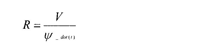
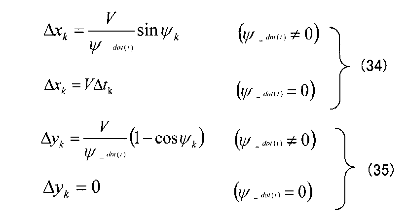
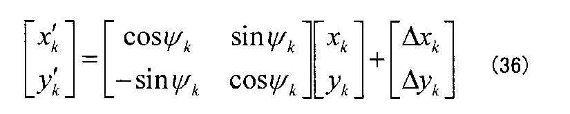
図15は、地物計測時間内の車両の移動を考慮した、地物の計測点の座標計算処理のフローチャートである。この処理は、前述の地物計測部13により行われる。まず、地物計測部13は、前の時刻で計測(あるいは推定)した自車の速度V(t-1)とヨーレートΨ_dot(t-1)を読み出し(ステップS50)、平面形状の道路標識である地物Aを対象としたn点の計測データを取得する(ステップS51)。次に、地物計測部13は、地物の計測データの左端のデータP1を基準の位置及び方位に設定する(ステップS52)。
次に、地物計測部13は、係数kに「1」をセットし(ステップS53)、係数kが計測データ数n以下か否かを判定する(ステップS54)。係数kが計測データ数n以下である場合(ステップS54:YES)、地物計測部13は点P1から点Pkまでの時間差Δtkを求める(ステップS55)。
次に、地物計測部13は、前述の式(33)を用いて、P1点からPk点までの角度変化Ψkを求め(ステップS56)、さらに式(34)、(35)を用いてP1点からPk点までの位置の差(Δxk,Δyk)を求める(ステップS57)。そして、地物計測部13は、式(36)を用いて、P1点を基準とした座標系におけるPk点での地物の座標を算出する(ステップS58)。
次に、地物計測部13は、係数kをインクリメントし(ステップS59)、ステップS54へ戻る。そして、係数kが計測データ数nを超えると(ステップS54:NO)、処理は終了する。こうして得られた計測データを用いてビーム角度φを算出することにより、地物の計測時間内の車両の移動分を補正し、移動距離ΔL及びヨー角変化量を高精度で算出することが可能となる。また、ヨー角変化量ΔΨを積分することにより、ヨー角Ψを算出することができ、ヨー角変化量ΔΨを所定時間Δtで除算することによりヨーレートΨ_dot(t)を算出することができる。さらに、移動距離ΔLを所定時間Δtで除算することにより車体速度Vを算出することができ、移動距離ΔLを積分することにより移動距離Lを算出することもできる。
[7]変形例
地物の平面に対してLiDARのビームが小さな角度で入射すると、距離計測値の誤差が大きくなるため、その状態で算出する車体速度とヨー角変化量にも誤差が大きくなる。従って、地物の法線ベクトルと車両から地物までの方向ベクトルとのなす角度φが大きいときは、誤差が大きいと判断し、車速センサの変換係数や、加速度センサとジャイロセンサの感度係数とオフセット係数を算出する際、重み付け値を小さくして平均化処理を行うことが好ましい。これにより、誤差の含まれる算出値の影響を小さくして、感度係数やオフセット係数を算出することができる。
地物の平面に対してLiDARのビームが小さな角度で入射すると、距離計測値の誤差が大きくなるため、その状態で算出する車体速度とヨー角変化量にも誤差が大きくなる。従って、地物の法線ベクトルと車両から地物までの方向ベクトルとのなす角度φが大きいときは、誤差が大きいと判断し、車速センサの変換係数や、加速度センサとジャイロセンサの感度係数とオフセット係数を算出する際、重み付け値を小さくして平均化処理を行うことが好ましい。これにより、誤差の含まれる算出値の影響を小さくして、感度係数やオフセット係数を算出することができる。
本発明は、移動体に搭載する装置に利用することができる。
7 車速センサ
8 加速度センサ
9 ジャイロセンサ
12 外界センサ
13 地物計測部
14 ビーム角度算出部
15 係数計算部
16 ヨー角変化量計算部
8 加速度センサ
9 ジャイロセンサ
12 外界センサ
13 地物計測部
14 ビーム角度算出部
15 係数計算部
16 ヨー角変化量計算部
Claims (12)
- 第1時刻及び第2時刻それぞれにおける、移動体から1の地物上の少なくとも2つの位置までのそれぞれの距離及び前記移動体からみた前記地物の方向と前記移動体の進行方向とがなす角度をそれぞれ取得する第1取得部と、
前記第1取得部の取得結果に基づき、前記第1時刻から前記第2時刻までの前記移動体の移動距離及び前記移動体の進行方向の変化量のうち少なくとも一方を算出する算出部と、
を備えることを特徴とする測定装置。 - 前記少なくとも2つの位置の座標を取得する第2取得部を更に備え、
前記算出部は、前記第1時刻及び前記第2時刻における、(i)前記移動体から前記少なくとも2つの位置までのそれぞれの距離及び前記少なくとも2つの位置の座標に基づいて算出される、前記地物の表面に対する法線と前記移動体からみた前記地物上の1つの位置の方向とがなす角度、並びに(ii)前記移動体からみた前記1つの位置の方向と前記移動体の進行方向とがなす角度、に基づき前記移動距離及び前記変化量のうち少なくとも一方を算出することを特徴とする請求項1に記載の測定装置。 - 前記第1取得部は、
前記移動体から前記1の地物の少なくとも3つの位置までの距離及び前記移動体から見た前記少なくとも3つの位置の方向から、前記少なくとも3つの位置の座標を計算する第1計算部と、
前記少なくとも3つの位置の座標に基づいて前記地物の表面の重心点の座標を計算し、前記移動体からみた前記重心点の方向を決定する第1方向決定部と、
前記少なくとも3つの位置の座標に基づいて前記地物の表面を規定する平面の式を計算し、前記平面の式に基づいて前記地物の表面に対する法線の方向を決定する第2方向決定部と、
前記重心点の方向と前記法線の方向とのなす角度を計算する第2計算部と、を備え、
前記算出部は、前記第1時刻及び第2時刻それぞれにおける、前記移動体から前記重心点までの距離、前記移動体からみた前記重心点の方向と前記移動体の進行方向とがなす角度、及び、前記重心点の方向と前記法線の方向とのなす角度に基づき、前記移動距離及び前記変化量のうち少なくとも一方を算出することを特徴とする請求項1に記載の測定装置。 - 前記第1取得部は、
前記移動体から前記1の地物の両端点までの距離、及び、前記移動体からみた前記両端点それぞれの方向がなす角度を計算する第3計算部と、
前記両端点までの距離、及び、前記移動体からみた前記両端点それぞれの方向がなす角に基づいて、前記1の地物の中点の座標を決定する第1中点決定部と、
前記移動体からみた前記中点の方向と、前記中点における前記地物の表面に対する法線の方向とがなす角度を計算する第4計算部と、を備え、
前記算出部は、前記第1時刻及び第2時刻それぞれにおける、前記移動体から前記中点までの距離、前記移動体からみた前記中点の方向と前記移動体の進行方向とがなす角度、及び、前記中点の方向と前記法線の方向とがなす角度に基づき、前記移動距離及び前記変化量のうち少なくとも一方を算出することを特徴とする請求項1に記載の測定装置。 - 前記第1取得部は、
前記移動体から前記1の地物の両端点までの距離、及び、前記移動体からみた前記両端点それぞれの方向のなす角度を計算する第5計算部と、
前記両端点までの距離、及び、前記移動体からみた前記両端点それぞれの方向がなす角に基づき前記1の地物の中点の座標を決定する第2中点決定部と、
前記移動体からみた前記両端点それぞれの方向が平行であるとみなして、前記移動体からみた前記中点の方向と、前記中点における前記地物の表面に対する法線の方向とがなす角度を計算する第6計算部と、を備え、
前記算出部は、前記第1時刻及び第2時刻それぞれにおける、前記移動体から前記中点までの距離、前記移動体からみた前記中点の方向と前記移動体の進行方向とがなす角度、及び、前記中点の方向と前記法線の方向とがなす角度に基づいて、前記移動距離及び前記変化量のうち少なくとも一方を算出することを特徴とする請求項1に記載の測定装置。 - 前記地物上の複数の位置のうちの1つを計測したときの前記移動体の位置である移動体位置を基準位置とし、前記複数の位置のうち前記基準位置以外の前記移動体位置で計測した位置の座標を、前記基準位置の座標系における座標に変換する座標変換部を備えることを特徴とする請求項1乃至5のいずれか一項に記載の測定装置。
- 前記算出部は前記移動距離を算出し、
前記測定装置は、前記移動距離に基づき算出される、単位時間あたりの移動距離に基づき、前記移動体に搭載される車速センサの前記第2時刻における出力結果から前記移動体の速度を算出するための第1情報を補正する第1補正部を更に備えることを特徴とする請求項1乃至6のいずれか一項に記載の測定装置。 - 前記算出部は前記移動距離を算出し、
前記測定装置は、前記移動距離に基づき算出される、単位時間あたりの移動距離に基づき、前記移動体に搭載される加速度センサの前記第2時刻における出力結果から前記移動体の速度を算出するための第2情報を補正する第2補正部を更に備えることを特徴とする請求項1乃至6のいずれか一項に記載の測定装置。 - 前記算出部は前記変化量を算出し、
前記測定装置は、前記変化量に基づき算出される、単位時間あたりの前記進行方向の変化量に基づき、前記移動体に搭載される角速度センサの前記第2時刻における出力結果から前記移動体のヨーレートを算出するための第3情報を補正する第3補正部を更に備えることを特徴とする請求項1乃至6のいずれか一項に記載の測定装置。 - 測定装置により実行される測定方法であって、
第1時刻及び第2時刻それぞれにおける、移動体から1の地物上の少なくとも2つの位置までのそれぞれの距離及び前記移動体からみた前記地物の方向と前記移動体の進行方向とがなす角度をそれぞれ取得する第1取得工程と、
前記第1取得部の取得結果に基づき、前記第1時刻から前記第2時刻までの前記移動体の移動距離及び前記移動体の進行方向の変化量のうち少なくとも一方を算出する算出工程と、
を備えることを特徴とする測定方法。 - コンピュータを備える測定装置によって実行されるプログラムであって、
第1時刻及び第2時刻それぞれにおける、移動体から1の地物上の少なくとも2つの位置までのそれぞれの距離及び前記移動体からみた前記地物の方向と前記移動体の進行方向とがなす角度をそれぞれ取得する第1取得部、
前記第1取得部の取得結果に基づき、前記第1時刻から前記第2時刻までの前記移動体の移動距離及び前記移動体の進行方向の変化量のうち少なくとも一方を算出する算出部、
として前記コンピュータを機能させることを特徴とするプログラム。 - 請求項11に記載のプログラムを記憶した記憶媒体。
Priority Applications (2)
| Application Number | Priority Date | Filing Date | Title |
|---|---|---|---|
| PCT/JP2016/060509 WO2017168654A1 (ja) | 2016-03-30 | 2016-03-30 | 測定装置、測定方法、及び、プログラム |
| JP2018507956A JP6707627B2 (ja) | 2016-03-30 | 2016-03-30 | 測定装置、測定方法、及び、プログラム |
Applications Claiming Priority (1)
| Application Number | Priority Date | Filing Date | Title |
|---|---|---|---|
| PCT/JP2016/060509 WO2017168654A1 (ja) | 2016-03-30 | 2016-03-30 | 測定装置、測定方法、及び、プログラム |
Publications (1)
| Publication Number | Publication Date |
|---|---|
| WO2017168654A1 true WO2017168654A1 (ja) | 2017-10-05 |
Family
ID=59963760
Family Applications (1)
| Application Number | Title | Priority Date | Filing Date |
|---|---|---|---|
| PCT/JP2016/060509 Ceased WO2017168654A1 (ja) | 2016-03-30 | 2016-03-30 | 測定装置、測定方法、及び、プログラム |
Country Status (2)
| Country | Link |
|---|---|
| JP (1) | JP6707627B2 (ja) |
| WO (1) | WO2017168654A1 (ja) |
Cited By (2)
| Publication number | Priority date | Publication date | Assignee | Title |
|---|---|---|---|---|
| CN110988989A (zh) * | 2019-12-05 | 2020-04-10 | 大连民族大学 | 一种爆破振动速度幅值和方向修正的方法 |
| GB2590429A (en) * | 2019-12-17 | 2021-06-30 | Stephen Mitchell John | Intelligent speed mapping |
Citations (9)
| Publication number | Priority date | Publication date | Assignee | Title |
|---|---|---|---|---|
| JPH10142336A (ja) * | 1996-11-06 | 1998-05-29 | Mitsubishi Motors Corp | 車両の走行レーン認識装置 |
| JP2005025497A (ja) * | 2003-07-02 | 2005-01-27 | Nissan Motor Co Ltd | 標識認識装置 |
| JP2006160116A (ja) * | 2004-12-08 | 2006-06-22 | Toyota Central Res & Dev Lab Inc | 車両運動推定装置及び移動体検出装置 |
| JP2008008783A (ja) * | 2006-06-29 | 2008-01-17 | Toyota Motor Corp | 車輪速パルス補正装置 |
| JP2008249639A (ja) * | 2007-03-30 | 2008-10-16 | Mitsubishi Electric Corp | 自己位置標定装置、自己位置標定方法および自己位置標定プログラム |
| US20100017128A1 (en) * | 2007-06-05 | 2010-01-21 | Gm Global Technology Operations, Inc. | Radar, Lidar and camera enhanced methods for vehicle dynamics estimation |
| JP2013072782A (ja) * | 2011-09-28 | 2013-04-22 | Aisin Aw Co Ltd | 移動体位置検出システム、移動体位置検出装置、移動体位置検出方法及びコンピュータプログラム |
| JP2014098613A (ja) * | 2012-11-14 | 2014-05-29 | Kddi Corp | ジャイロセンサの較正機能を備えた角速度測定装置、較正プログラム及び方法 |
| US20150025786A1 (en) * | 2012-02-28 | 2015-01-22 | Continental Automotive Gmbh | Method And Device For Determining The Speed And/Or Position Of A Vehicle |
-
2016
- 2016-03-30 JP JP2018507956A patent/JP6707627B2/ja active Active
- 2016-03-30 WO PCT/JP2016/060509 patent/WO2017168654A1/ja not_active Ceased
Patent Citations (9)
| Publication number | Priority date | Publication date | Assignee | Title |
|---|---|---|---|---|
| JPH10142336A (ja) * | 1996-11-06 | 1998-05-29 | Mitsubishi Motors Corp | 車両の走行レーン認識装置 |
| JP2005025497A (ja) * | 2003-07-02 | 2005-01-27 | Nissan Motor Co Ltd | 標識認識装置 |
| JP2006160116A (ja) * | 2004-12-08 | 2006-06-22 | Toyota Central Res & Dev Lab Inc | 車両運動推定装置及び移動体検出装置 |
| JP2008008783A (ja) * | 2006-06-29 | 2008-01-17 | Toyota Motor Corp | 車輪速パルス補正装置 |
| JP2008249639A (ja) * | 2007-03-30 | 2008-10-16 | Mitsubishi Electric Corp | 自己位置標定装置、自己位置標定方法および自己位置標定プログラム |
| US20100017128A1 (en) * | 2007-06-05 | 2010-01-21 | Gm Global Technology Operations, Inc. | Radar, Lidar and camera enhanced methods for vehicle dynamics estimation |
| JP2013072782A (ja) * | 2011-09-28 | 2013-04-22 | Aisin Aw Co Ltd | 移動体位置検出システム、移動体位置検出装置、移動体位置検出方法及びコンピュータプログラム |
| US20150025786A1 (en) * | 2012-02-28 | 2015-01-22 | Continental Automotive Gmbh | Method And Device For Determining The Speed And/Or Position Of A Vehicle |
| JP2014098613A (ja) * | 2012-11-14 | 2014-05-29 | Kddi Corp | ジャイロセンサの較正機能を備えた角速度測定装置、較正プログラム及び方法 |
Cited By (2)
| Publication number | Priority date | Publication date | Assignee | Title |
|---|---|---|---|---|
| CN110988989A (zh) * | 2019-12-05 | 2020-04-10 | 大连民族大学 | 一种爆破振动速度幅值和方向修正的方法 |
| GB2590429A (en) * | 2019-12-17 | 2021-06-30 | Stephen Mitchell John | Intelligent speed mapping |
Also Published As
| Publication number | Publication date |
|---|---|
| JP6707627B2 (ja) | 2020-06-10 |
| JPWO2017168654A1 (ja) | 2019-02-14 |
Similar Documents
| Publication | Publication Date | Title |
|---|---|---|
| JP2022113746A (ja) | 判定装置 | |
| WO2019188745A1 (ja) | 情報処理装置、制御方法、プログラム及び記憶媒体 | |
| JP4199553B2 (ja) | ハイブリッド航法装置 | |
| CN111380573B (zh) | 用于校准运动的对象传感器的取向的方法 | |
| US12085653B2 (en) | Position estimation device, estimation device, control method, program and storage media | |
| JP7155284B2 (ja) | 計測精度算出装置、自己位置推定装置、制御方法、プログラム及び記憶媒体 | |
| WO2017150106A1 (ja) | 車載装置、及び、推定方法 | |
| JP7487388B2 (ja) | 測定装置、測定方法、及び、プログラム | |
| JP2024161105A (ja) | 自己位置推定装置、制御方法、プログラム及び記憶媒体 | |
| WO2018212292A1 (ja) | 情報処理装置、制御方法、プログラム及び記憶媒体 | |
| JPWO2017168586A1 (ja) | 算出装置、制御方法、プログラム及び記憶媒体 | |
| JPWO2017109978A1 (ja) | 距離推定装置、距離推定方法及びプログラム | |
| JP6707627B2 (ja) | 測定装置、測定方法、及び、プログラム | |
| JP6503477B2 (ja) | 距離推定装置、距離推定方法及びプログラム | |
| CN105759292B (zh) | 一种差分gps与机器人的相对位置参数标定方法及系统 | |
| WO2017168588A1 (ja) | 測定装置、測定方法、及び、プログラム | |
| JP2017181195A (ja) | 測定装置、測定方法、及び、プログラム | |
| JP2017177940A (ja) | 算出装置、制御方法、プログラム及び記憶媒体 | |
| TWI394944B (zh) | 車輛姿態估測系統與方法 | |
| JP3551661B2 (ja) | ナビゲーション装置 | |
| CN114080548A (zh) | 车载传感器装置 | |
| WO2017109976A1 (ja) | 距離推定装置、距離推定方法及びプログラム | |
| WO2018163750A1 (ja) | 距離推定装置、距離推定方法及びプログラム | |
| WO2019124279A1 (ja) | 情報処理装置 | |
| WO2018212290A1 (ja) | 情報処理装置、制御方法、プログラム及び記憶媒体 |
Legal Events
| Date | Code | Title | Description |
|---|---|---|---|
| WWE | Wipo information: entry into national phase |
Ref document number: 2018507956 Country of ref document: JP |
|
| NENP | Non-entry into the national phase |
Ref country code: DE |
|
| 121 | Ep: the epo has been informed by wipo that ep was designated in this application |
Ref document number: 16896873 Country of ref document: EP Kind code of ref document: A1 |
|
| 122 | Ep: pct application non-entry in european phase |
Ref document number: 16896873 Country of ref document: EP Kind code of ref document: A1 |