WO2017168501A1 - タイヤ状態監視装置 - Google Patents
タイヤ状態監視装置 Download PDFInfo
- Publication number
- WO2017168501A1 WO2017168501A1 PCT/JP2016/059855 JP2016059855W WO2017168501A1 WO 2017168501 A1 WO2017168501 A1 WO 2017168501A1 JP 2016059855 W JP2016059855 W JP 2016059855W WO 2017168501 A1 WO2017168501 A1 WO 2017168501A1
- Authority
- WO
- WIPO (PCT)
- Prior art keywords
- shaped terminal
- terminal portion
- gate
- circuit board
- monitoring device
- Prior art date
- Legal status (The legal status is an assumption and is not a legal conclusion. Google has not performed a legal analysis and makes no representation as to the accuracy of the status listed.)
- Ceased
Links
Images





Classifications
-
- B—PERFORMING OPERATIONS; TRANSPORTING
- B60—VEHICLES IN GENERAL
- B60C—VEHICLE TYRES; TYRE INFLATION; TYRE CHANGING; CONNECTING VALVES TO INFLATABLE ELASTIC BODIES IN GENERAL; DEVICES OR ARRANGEMENTS RELATED TO TYRES
- B60C23/00—Devices for measuring, signalling, controlling, or distributing tyre pressure or temperature, specially adapted for mounting on vehicles; Arrangement of tyre inflating devices on vehicles, e.g. of pumps or of tanks; Tyre cooling arrangements
- B60C23/02—Signalling devices actuated by tyre pressure
- B60C23/04—Signalling devices actuated by tyre pressure mounted on the wheel or tyre
-
- B—PERFORMING OPERATIONS; TRANSPORTING
- B60—VEHICLES IN GENERAL
- B60C—VEHICLE TYRES; TYRE INFLATION; TYRE CHANGING; CONNECTING VALVES TO INFLATABLE ELASTIC BODIES IN GENERAL; DEVICES OR ARRANGEMENTS RELATED TO TYRES
- B60C23/00—Devices for measuring, signalling, controlling, or distributing tyre pressure or temperature, specially adapted for mounting on vehicles; Arrangement of tyre inflating devices on vehicles, e.g. of pumps or of tanks; Tyre cooling arrangements
- B60C23/02—Signalling devices actuated by tyre pressure
- B60C23/04—Signalling devices actuated by tyre pressure mounted on the wheel or tyre
- B60C23/0408—Signalling devices actuated by tyre pressure mounted on the wheel or tyre transmitting the signals by non-mechanical means from the wheel or tyre to a vehicle body mounted receiver
- B60C23/0422—Signalling devices actuated by tyre pressure mounted on the wheel or tyre transmitting the signals by non-mechanical means from the wheel or tyre to a vehicle body mounted receiver characterised by the type of signal transmission means
- B60C23/0433—Radio signals
- B60C23/0447—Wheel or tyre mounted circuits
- B60C23/0452—Antenna structure, control or arrangement
-
- G—PHYSICS
- G08—SIGNALLING
- G08C—TRANSMISSION SYSTEMS FOR MEASURED VALUES, CONTROL OR SIMILAR SIGNALS
- G08C17/00—Arrangements for transmitting signals characterised by the use of a wireless electrical link
Definitions
- the present invention relates to a tire condition monitoring device that is attached to a tire wheel and detects the condition of the tire and wirelessly transmits it.
- Patent Document 1 As a conventional tire condition monitoring device, a device equipped with a loop antenna for wireless transmission is known (for example, see Patent Document 1).
- the present invention aims to provide a tire condition monitoring apparatus that can satisfy such a demand.
- the invention of claim 1 is a tire condition monitoring device that is attached to a tire wheel, detects the condition of the tire and wirelessly transmits the tire condition, and is mounted on the circuit board and the circuit board. Wireless transmission is performed using a battery as a power source of the mounted circuit, a bus bar protruding from the circuit board and connecting the battery and the mounted circuit, and a closed circuit including the bus bar as a loop antenna.
- a tire condition monitoring device including a transmission circuit.
- the bus bar includes a gate-shaped terminal portion formed by connecting a pair of leg portions protruding from one surface of the front and back surfaces of the circuit board with a bridging portion, and the battery. 2.
- the closed circuit including the one pair of electrodes in contact with the bridge portion and the pair of leg portions of the gate-shaped terminal portion and the bridge portion in series is used as the loop antenna. It is a tire condition monitoring apparatus of description.
- the gate-shaped terminal portion connects the first portion and the second portion of the mounting circuit so as to be at the same potential in terms of direct current, and the first portion and the portal shape.
- the tire condition monitoring device according to claim 2, wherein an AC blocking section that disconnects the terminal section in an AC manner is provided.
- the bus bar is provided with an L-shaped terminal portion that protrudes and bends from one surface on the front and back sides of the circuit board, and the battery has a front end side with respect to the bent portion of the L-shaped terminal portion.
- the closed circuit is sandwiched between the cantilever portion and the bridge portion, and includes the one leg portion of the gate-shaped terminal portion, the bridge portion, the battery, and the L-shaped terminal portion in series.
- the first gate-shaped terminal portion and the second gate-shaped terminal portion are provided on one surface and the other surface of the circuit board, and the first gate shape.
- One leg portion of the terminal portion and one leg portion of the second portal terminal portion are connected, and the first portal terminal portion and the second portal terminal portion are provided in series.
- the bus bar is provided with a pair of L-shaped terminal portions protruding and bent from one surface of the circuit board, and the battery is provided on the one surface of the circuit board.
- the closed circuit that is disposed oppositely and is sandwiched between the cantilever portions on the tip side of the bent portion of the pair of L-shaped terminal portions, and includes the pair of L-shaped terminal portions and the battery.
- the mounting circuit of the circuit board and the battery are connected by a bus bar protruding from the circuit board. And since the closed circuit including the bus bar is used as a loop antenna and the detection result of the tire condition is transmitted wirelessly, it is possible to reduce the size and cost compared to the conventional one having a loop antenna dedicated to wireless transmission. become.
- the bus bar may extend sideways substantially parallel to the front and back surfaces of the circuit board, or may protrude from one or both sides of the front and back surfaces of the circuit board.
- the bus bar is provided with an L-shaped terminal portion or a gate-shaped terminal portion protruding from one surface of the front and back of the circuit board and connected to the battery.
- the battery can be disposed opposite to the circuit board to achieve a compact configuration.
- the gate-shaped terminal portion is used to make the first part and the second part in the mounting circuit have the same potential in a direct current manner. Effective use of the shaped terminal portion is achieved.
- a closed circuit is provided in which a battery is sandwiched between an L-shaped terminal portion and a gate-shaped terminal portion, and a pair of leg portions and a bridging portion are connected in series.
- both the L-shaped terminal portion, the one leg portion, the bridge portion, and the closed circuit including the battery may be used as the loop antenna.
- the first gate-shaped terminal portion protruding from one surface of the front and back of the circuit board and the second gate-shaped terminal portion protruding from the other surface are included.
- a closed circuit may be used as a loop antenna.
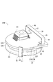
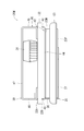
- FIG. 1 is a side sectional view showing a state in which a tire condition monitoring device according to a first embodiment of the present invention is attached to a tire wheel.
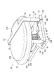
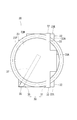
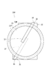
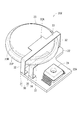
- Perspective view of tire condition monitoring device Top view of tire condition monitoring device Circuit diagram of tire condition monitoring device Conceptual diagram of a vehicle equipped with a tire condition monitoring device The top view of the tire condition monitoring device of a 2nd embodiment Circuit diagram of tire condition monitoring device The perspective view of the tire condition monitoring apparatus of 3rd Embodiment Side view of tire condition monitoring device Circuit diagram of tire condition monitoring device The perspective view of the tire condition monitoring apparatus of 4th Embodiment The perspective view of the tire condition monitoring apparatus of 5th Embodiment Circuit diagram of tire condition monitoring device according to modification
- reference numeral 10 denotes a tire valve, which is press-fitted into a valve mounting hole 92 formed in the rim 91 of the tire wheel 90. And the tire condition monitoring apparatus 20 of this embodiment is attached to the part located inside the rim 91 among the tire valves 10.
- the tire condition monitoring device 20 accommodates a circuit board 22, a button battery 23, and the like inside a case 21, and only the portion accommodated in the case 21 is shown in FIG.
- the circuit board 22 has, for example, a shape having a notch 22C on one long side of a rectangle.
- the pressure sensor 25, the temperature sensor 26, the acceleration sensor 49, the reception circuit 27, the transmission circuit 41, and the control IC 24 shown in FIG. are connected by printed wiring, vias, through-holes, and the like to constitute the mounting circuit 40 according to the present invention.
- the receiving antenna 27A connected to the receiving circuit 27 is received in, for example, the notch 22C described above.
- the button battery 23 has a diameter substantially the same as the longitudinal direction of the entire circuit board 22 as shown in FIG. As shown in FIG. 2, the button battery 23 is held in a state facing the circuit board 22 with a space therebetween by the bus bar 30 protruding from the front side surface 22 ⁇ / b> A of the circuit board 22.
- the bus bar 30 includes a gate-shaped terminal portion 31 and an L-shaped terminal portion 35 as shown in FIG.
- the gate-shaped terminal portion 31 has a structure in which one end portion of a pair of leg portions 32, 32 is bridged by a bridging portion 33.
- contact pieces 34A and 34A are bent at right angles from the other end portions of the pair of leg portions 32 and 32 toward the sides approaching each other. ing.
- a part of each abutting piece 34A is cut out in a cantilever shape to form a positioning piece 34B extending straight from each leg 32.
- a pair of short side surfaces 22E and 22E (one side surface 22E in FIG. 2) of the outer edge of the circuit board 22. Only a groove portion 22D is formed near one end.
- the contact piece 34A is superposed on the front side surface 22A of the circuit board 22 and soldered in a state where the positioning piece 34B is received in the groove 22D.
- the protrusion 33 ⁇ / b> A protrudes from the center of the bridging portion 33 on the side away from the center of the circuit board 22.
- the L-shaped terminal portion 35 includes a leg portion 36 that is shorter than the leg portion 32 of the gate-shaped terminal portion 31 and a cantilever portion 37 bent at a right angle from one end portion of the leg portion 36.
- the other end portion of the leg portion 36 of the L-shaped terminal portion 35 is also provided with a contact piece 34 ⁇ / b> A and a positioning piece 34 ⁇ / b> B like the leg portion 32 of the gate-shaped terminal portion 31.
- the groove 22D is also formed on one side surface 22E of the circuit board 22 near the other end, and the contact piece 34A is connected to the circuit in a state where the positioning piece 34B of the L-shaped terminal portion 35 is received therein.
- the substrate 22 is superposed on the front side surface 22A and soldered.
- the cantilever portion 37 extends from one end portion of the leg portion 36 toward the center portion side of the circuit board 22. Then, the positive electrode 23P of the button battery 23 is directed to the circuit board 22 side, the cantilever part 37 is addressed, and the bridging part 33 is addressed to the negative electrode 23M of the button battery 23 from the side opposite to the circuit board 22.
- the button battery 23 is sandwiched between the cantilever portion 37 and the bridging portion 33.
- the control IC 24, the transmission circuit 41, etc. of the mounting circuit 40 are arranged.
- the cantilever portion 37 and the bridging portion 33 are brazed to the button battery 23.
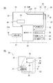
- FIG. 4A the circuit configuration of the tire condition monitoring device 20 is shown separately for the bus bar 30 (the gate-shaped terminal portion 31 and the L-shaped terminal portion 35) and the mounting circuit 40 other than the bus bar 30,
- FIG. 4B shows a simplified portion of the circuit of the tire condition monitoring device 20 related to wireless transmission.
- the gate-shaped terminal portion 31 and the L-shaped terminal portion 35 are indicated by thick lines.
- the positive electrode 23P of the button battery 23 is connected to the power receiving terminal A of the control IC 24 via the L-shaped terminal portion 35, and the negative electrode 23M of the button battery 23 is connected to the portal terminal portion.
- 31 is connected to the ground terminal B of the control IC 24 through the bridging portion 33 and the one leg portion 32.
- a ground conductor 29 made of, for example, a relatively large solder layer or metal block is mounted on the circuit board 22, and the ground terminal B of the control IC 24 is connected to the ground conductor 29.
- the input of the transmission circuit 41 is connected to the output terminal C of the control IC 24, and the output of the transmission circuit 41 passes through the other leg portion 32 of the gate-shaped terminal portion 31 and the bridging portion 33.
- the negative electrode 23M is connected.
- the transmission circuit 41 is provided with a DC blocking unit (specifically, a conductor) (not shown) that blocks DC.
- the ground conductor 29 is located in front of the ground conductor 29 (that is, the common connection portion of the gate-shaped terminal portion 31, the ground terminal B, and the ground conductor 29, and the ground conductor).
- Inductor 28 for restricting the output of transmission circuit 41 from flowing into conductor 29 for ground may be provided between body 29).
- the ground conductor 29 corresponds to the “first portion” of the present invention
- the output terminal C of the control IC 24 corresponds to the “second portion” of the present invention
- the inductor 28 corresponds to the “second portion” of the present invention.
- the tire condition monitoring device 20 includes an AC closed circuit C1 including the control IC 24, the transmission circuit 41, one leg 32, the bridging part 33, and the other leg 32 in series (FIG. 4B). And a closed circuit C2 (see FIG. 4B) having an AC 24 for control, a transmission circuit 41, one leg 32, a bridging portion 33, and an L-shaped terminal portion 35 in series. Yes. Then, the control IC 24 performs wireless transmission using these closed circuits C1 and C2 as loop antennas (specifically, minute loop antennas).
- the tire condition monitoring device 20 receives the inquiry signal from the transmission circuit 52 of the main body device 50 mounted on the vehicle main body 99 shown in FIG. 5, and the reception circuit 27 of the tire condition monitoring device 20 receives it. If the acceleration sensor 49 detects the start or stop of the vehicle 100, the control IC 24 detects the pressure and temperature in the tire 97 as the state of the tire 97 by the pressure sensor 25 and the temperature sensor 26. To do. Then, the control IC 24 controls the transmission circuit 41, modulates the detection result with a high frequency (for example, 300 to 400 [MHz]) carrier wave, and outputs it to the closed circuits C1 and C2.
- a high frequency for example, 300 to 400 [MHz]
- the closed circuits C1 and C2 become loop antennas, and the detection result of the state of the tire 97 is wirelessly transmitted.
- the control IC 51 of the main body device 50 performs abnormality determination or outputs a detection result to a monitor (not shown).
- the state of the tire 97 can also be confirmed with a smart phone by downloading a predetermined application onto the smart phone.
- the mounting circuit 40 of the circuit board 22 and the button battery 23 are connected by the bus bar 30 protruding from the circuit board 22. Since the closed circuit C1 and C2 including the bus bar 30 is used as a loop antenna to wirelessly transmit the detection result of the state of the tire 97, the size and size can be reduced as compared with the conventional one having a loop antenna dedicated to wireless transmission. Cost reduction is possible.
- the bus bar 30 is provided with an L-shaped terminal portion 35 and a gate-shaped terminal portion 31 protruding from the front side surface 22A of the circuit board 22 and connected to the button battery 23, so that the button battery 23 is disposed opposite to the circuit board 22. A compact configuration can be achieved. Furthermore, the gate-shaped terminal portion 31 is used to effectively make the output terminal C of the control IC 24 and the ground conductor 29 have the same potential in terms of direct current.
- the tire condition monitoring device 20V of the present embodiment includes an L-shaped terminal portion 35 instead of the gate-shaped terminal portion 31 in the tire condition monitoring device 20 of the first embodiment, and includes two L-shaped terminals.
- the button battery 23 is sandwiched between the cantilever portions 37, 37 of the portions 35, 35.
- one L-shaped terminal portion 35 includes a power receiving terminal A of the control IC 24 and a positive electrode 23P of the button battery 23, as in the tire condition monitoring device 20 of the first embodiment. Are connected.
- the other L-shaped terminal portion 35 instead of the gate-shaped terminal portion 31 has one end connected to the negative electrode 23M of the button battery 23 and the other end connected to the ground terminal B of the control IC 24 via the inductor 28. Yes.
- a ground conductor 29 is connected to a common connection portion between the ground terminal B and the inductor 28.
- the output of the transmission circuit 41 connected to the output terminal C of the control IC 24 is connected to a common connection portion between the inductor 28 and the L-shaped terminal portion 35.
- a closed circuit C3 including a pair of L-shaped terminal portions 35 and 35 and a button battery 23 in series is configured as shown in FIG. 7B. .
- the transmission circuit 41 modulates the detection result of the state of the tire 97 with a high-frequency carrier wave and outputs it to the closed circuit C3, whereby the closed circuit C3 becomes a loop antenna, and the detection result of the state of the tire 97 is obtained. Wirelessly transmitted.
- the tire condition monitoring device 20W of the present embodiment is shown in FIGS.
- the circuit board 22 of the tire condition monitoring device 20W has a shape in which a semicircle is combined with one side of a quadrangle. That is, the circuit board 22 includes a semicircular portion 22N and a rectangular portion 22M.
- the diameter of the semicircular portion 22N is substantially the same as the diameter of the button battery 23, and the button battery 23 and the semicircular portion 22N are held by the bus bar 30 in a state where they are arranged on the concentric axis. Yes.
- the bus bar 30 includes an L-shaped terminal portion 35, a first gate-shaped terminal portion 42, and a second gate-shaped terminal portion 45.
- the second gate-shaped terminal portion 45 includes a pair of leg portions 46 and 46 from a bridging portion 47 extending in parallel with the side opposite to the semicircular portion 22N of the circuit board 22.
- a structure bent at a right angle is formed, the leg portions 46 are fixed to the front side surface 22A of the rectangular portion 22M of the circuit board 22, and the bridging portion 47 is opposed to the circuit board 22 with a space therebetween.
- the first gate terminal portion 42 has a pair of leg portions 43, 43 at a right angle from a bridge portion 44 extending in parallel with the bridge portion 47 of the second gate terminal portion 45.
- the leg portions 43 and 43 are fixed to the back side surface 22B of the rectangular portion 22M of the circuit board 22, and the bridging portion 44 is opposed to the circuit board 22 with a space therebetween.
- one leg 43 of the first gate-shaped terminal portion 42 penetrates the slit 22 ⁇ / b> F formed in the circuit board 22 and protrudes to the front side surface 22 ⁇ / b> A side of the circuit board 22. It is connected to one leg portion 46 of the two portal terminal portions 45. Further, as shown in FIG.
- the amount of protrusion from the circuit board 22 is larger in the second gate terminal portion 45 than in the first gate terminal portion 42, and the second gate terminal.
- a control IC 24 is mounted on the front side surface 22A side of the circuit board 22 from which the portion 45 projects.
- the mounting circuits on the front and back of the circuit board 22 are connected by vias, through holes, and the like.
- the leg portion 36 of the L-shaped terminal portion 35 is disposed on the outer edge portion of the semicircular portion 22N of the circuit board 22 and protrudes from the back side surface 22B, and the cantilever portion 37 extends from the leg portion 36 to the semicircular portion 22N. It extends toward the center of the circle.
- the negative electrode 23M of the button battery 23 abuts against the bridging portion 44 of the first gate-shaped terminal portion 42 from the opposite side of the circuit board 22, and the cantilever portion 37 of the L-shaped terminal portion 35 contacts the positive electrode 23P of the button battery 23. Are in contact. That is, the button battery 23 is sandwiched between the first gate-shaped terminal portion 42 and the L-shaped terminal portion 35.
- FIG. 10 shows a circuit configuration of the tire condition monitoring device 20W.
- the portal terminal portion 31 of the tire condition monitoring device 20 of the first embodiment and The second gate terminal portion 45 is interposed between the control IC 24 and the ground terminal B. That is, the closed circuit C4 including the first gate-shaped terminal portion 42 and the second gate-shaped terminal portion 45 in series is used as a loop antenna.
- the first gate-shaped terminal portion 42 protruding from one surface of the front and back of the circuit board 22 and the second gate-shaped terminal portion protruding from the other surface. Since the closed circuit C4 including 45 is provided as a loop antenna, the balance of the protruding portions on the front and back of the circuit board 22 is improved, and a compact configuration can be achieved.
- the tire condition monitoring device 20X of the present embodiment is shown in FIG. 11, and the bridge portion 33 of the gate-shaped terminal portion 31 and the cantilever portion of the L-shaped terminal portion 35 provided on the front side surface 22A of the circuit board 22. 37 are arranged in parallel.
- the cantilever portion 37 is positioned below the bridging portion 33, the button battery 23 is sandwiched between the cantilever portion 37 and the bridging portion 33, and the positive electrode 23 ⁇ / b> P of the button battery 23 is the L-shaped terminal portion 35.
- the negative electrode 23 ⁇ / b> M of the button battery 23 is connected to the portal terminal portion 31.
- the button battery 23 is sandwiched between the cantilever portion 37 and the bridging portion 33 at a position off the center, and the opposite side of the sandwiched portion projects laterally from the circuit board 22. Further, the circuit configuration of the tire condition monitoring device 20X is the same as that of the tire condition monitoring device 20 of the first embodiment shown in FIG.
- the tire condition monitoring device 20Y of this embodiment is shown in FIG. 12, and the bus bar 30 includes a crank-shaped terminal portion 60 and an L-shaped terminal portion 61.
- the L-shaped terminal portion 61 rises from one side edge portion of the front side surface 22 ⁇ / b> A of the circuit board 22, bends at a right angle, and extends in a cantilever shape to the side of the circuit board 22.
- the crank-shaped terminal portion 60 stands up from a position away from the crank-shaped terminal portion 60 in one side edge portion of the front side surface 22A of the circuit board 22 and then bends in a crank shape. Thus, it extends in a cantilever shape to the side of the circuit board 22.
- the button battery 23 is sandwiched between the crank-type terminal portion 60 and the L-type terminal portion 61 at a side position of the circuit board 22.
- the circuit configuration of the tire condition monitoring device 20Y is the same as that of the tire condition monitoring device 20V of the second embodiment shown in FIG.
- the negative electrode 23M of the button battery 23 is connected to the ground of the mounting circuit 40 by the gate-shaped terminal portion 31, but the positive electrode 23P of the button battery 23 is connected to the mounting circuit. It is good also as a structure connected to 40 ground.
- the button battery 23 is provided as a battery, but a battery other than the button battery may be provided.
Landscapes
- Engineering & Computer Science (AREA)
- Mechanical Engineering (AREA)
- Computer Networks & Wireless Communication (AREA)
- Physics & Mathematics (AREA)
- General Physics & Mathematics (AREA)
- Arrangements For Transmission Of Measured Signals (AREA)
- Measuring Fluid Pressure (AREA)
Abstract
【課題】小型化及び低コスト化が可能なタイヤ状態監視装置を提供する。 【解決手段】本発明のタイヤ状態監視装置では、回路基板から突出するバスバーが設けられ、このバスバーにより回路基板の実装回路と電池との間が接続されている。そして、そのバスバーを含む閉回路をループアンテナとして利用してタイヤの状態の検出結果を無線送信するので、無線送信専用にループアンテナを備えた従来のタイヤ状態監視装置に比べて、小型化及び低コスト化が可能になる。
Description
本発明は、タイヤホイールに取り付けられ、タイヤの状態を検出して無線送信するタイヤ状態監視装置に関する。
従来のタイヤ状態監視装置として、無線送信を行うためにループアンテナを備えたものが知られている(例えば、特許文献1参照)。
しかしながら、上述した従来のタイヤ状態監視装置に対して、小型化及び低コスト化の要望があり、本発明は、そのような要望を満たすことが可能なタイヤ状態監視装置の提供を目的とする。
上記目的を達成するためになされた請求項1の発明は、タイヤホイールに取り付けられ、タイヤの状態を検出して無線送信するタイヤ状態監視装置であって、回路基板と、前記回路基板に実装されている実装回路の電源である電池と、前記回路基板から突出して、前記電池と前記実装回路との間を接続するバスバーと、前記バスバーを含む閉回路をループアンテナとして利用して無線送信を行う送信回路とを備えるタイヤ状態監視装置である。
請求項2の発明は、前記バスバーには、前記回路基板の表裏の一方の面から突出した1対の脚部の間を架橋部で連絡してなる門形端子部が備えられて、前記電池の一方の電極が、前記架橋部に当接され、前記門形端子部の前記1対の脚部と前記架橋部とを直列に備える前記閉回路が前記ループアンテナとして利用される請求項1に記載のタイヤ状態監視装置である。
請求項3の発明は、前記門形端子部は、前記実装回路における第1の部位と第2の部位とを直流的に同電位となるように接続し、前記第1の部位と前記門形端子部との間を交流的に断絶する交流遮断部が設けられている請求項2に記載のタイヤ状態監視装置である。
請求項4の発明は、前記バスバーには、前記回路基板の表裏の一方の面から突出しかつ屈曲したL形端子部が備えられ、前記電池が、前記L形端子部のうち屈曲部分より先端側の片持ち梁部と前記架橋部との間に挟持され、前記門形端子部の一方の前記脚部と前記架橋部と前記電池と前記L形端子部とを直列に備える前記閉回路が前記ループアンテナとして利用される請求項2又は3に記載のタイヤ状態監視装置である。
請求項5の発明は、前記回路基板の表裏の一方の面と他方の面とに第1の前記門形端子部と第2の前記門形端子部とが設けられ、前記第1の門形端子部の一方の前記脚部と前記第2の門形端子部の一方の脚部とが接続されて、前記第1の門形端子部と前記第2の門形端子部とを直列に備える前記閉回路が前記ループアンテナとして利用される請求項2乃至4の何れか1の請求項に記載のタイヤ状態監視装置である。
請求項6の発明は、前記バスバーには、前記回路基板の表裏の一方の面から突出しかつ屈曲した1対のL形端子部が備えられ、前記電池は、前記回路基板の前記一方の面に対向配置されて、前記1対のL形端子部のうち屈曲部分より先端側の片持ち梁部同士の間に挟持され、前記1対のL形端子部と前記電池とを含む前記閉回路が前記ループアンテナとして利用される請求項1に記載のタイヤ状態監視装置である。
請求項1のタイヤ状態監視装置では、回路基板から突出するバスバーにより回路基板の実装回路と電池との間が接続されている。そして、そのバスバーを含む閉回路をループアンテナとして利用してタイヤの状態の検出結果を無線送信するので、無線送信専用にループアンテナを備えた従来のものに比べて小型化及び低コスト化が可能になる。
ここで、バスバーは、回路基板の表裏の面と略平行になって側方に延びていてもよいし、回路基板の表裏の片面又は両面から突出していてもよい。また、例えば、請求項2及び請求項6のタイヤ状態監視装置のように、バスバーに回路基板の表裏の一方の面から突出したL形端子部又は門形端子部を設けて電池に接続することで、回路基板に電池を対向配置してコンパクトな構成にすることができる。
さらには、請求項3のタイヤ状態監視装置のように、門形端子部を、実装回路における第1の部位と第2の部位とを直流的に同電位にするために使用することで、門形端子部の有効利用が図られる。
また、請求項4のタイヤ状態監視装置のように、L形端子部と門形端子部とで電池を挟持し、門形端子部の1対の脚部と架橋部とを直列に備える閉回路と、L形端子部と一方の脚部と架橋部と電池とを含む閉回路との両方をループアンテナとして利用してもよい。
さらには、請求項5のタイヤ状態監視装置のように、回路基板の表裏の一方の面から突出した第1の門形端子部と他方の面から突出した第2の門形端子部とを含む閉回路をループアンテナとして利用してもよく、そのような構成にすれば、回路基板の表裏における突出部分のバランスがよくなり、コンパクトな構成にすることができる。
[第1実施形態]
以下、本発明の一実施形態を、図1~図5に基づいて説明する。図1において、符号10は、タイヤバルブであって、タイヤホイール90のリム91に形成されたバルブ取付孔92に圧入されている。そして、そのタイヤバルブ10のうちリム91の内側に位置する部分に本実施形態のタイヤ状態監視装置20が取り付けている。
以下、本発明の一実施形態を、図1~図5に基づいて説明する。図1において、符号10は、タイヤバルブであって、タイヤホイール90のリム91に形成されたバルブ取付孔92に圧入されている。そして、そのタイヤバルブ10のうちリム91の内側に位置する部分に本実施形態のタイヤ状態監視装置20が取り付けている。
タイヤ状態監視装置20は、ケース21の内部に回路基板22、ボタン電池23等を収容してなり、図2には、そのケース21に収容されている部分のみが示されている。同図に示すように、回路基板22は、例えば長方形の一方の長辺に切欠部22Cを備えた形状をなしている。回路基板22の表側面22A又は裏側面22Bには、図4(A)に示した圧力センサ25、温度センサ26、加速度センサ49、受信回路27、送信回路41及び制御用IC24が実装されかつ、それらがプリント配線、ビア、スルーホール等で接続されて本発明に係る実装回路40が構成されている。なお、受信回路27に接続されている受信用アンテナ27Aは、例えば、上記した切欠部22Cに受容されている。
ボタン電池23は、図3に示すように回路基板22全体の長手方向と略同一の直径を有する。そして、図2に示すように、回路基板22の表側面22Aから突出したバスバー30により、ボタン電池23が回路基板22に対して空間を空けて対向した状態に保持されている。
バスバー30は、図3に示すように、門形端子部31とL形端子部35とからなる。門形端子部31は、図2に示すように、1対の脚部32,32の一端部間を架橋部33で架橋した構造をなしている。また、1対の脚部32,32の他端部からは、互いに接近する側に当接片34A,34A(図2には一方の当接片34Aのみが示されている)が直角曲げされている。さらに、各当接片34Aの一部が片持ち梁状に切り離されて、各脚部32から真っ直ぐ延びた位置決片34Bになっている。また、これら1対の脚部32,32の位置決片34B,34Bに対応して、回路基板22の外縁のうち1対の短辺側の側面22E,22E(図2には一方の側面22Eのみが示されている)には、一端寄り位置に溝部22Dが形成されている。そして、位置決片34Bが溝部22Dに受容された状態で当接片34Aが回路基板22の表側面22Aに重ねられて半田付けされている。なお、架橋部33の中央からは、回路基板22の中央部から離れる側に突部33Aが張り出している。
L形端子部35は、門形端子部31の脚部32より短い脚部36と、その脚部36の一端部から直角に曲がった片持ち梁部37とを備える。また、L形端子部35の脚部36の他端部にも、門形端子部31の脚部32と同様に当接片34Aと位置決片34Bとが備えられている。そして、回路基板22における一方の側面22Eには、他端寄り位置にも溝部22Dが形成され、そこにL形端子部35の位置決片34Bが受容された状態で、当接片34Aが回路基板22の表側面22Aに重ねられて半田付けされている。また、片持ち梁部37は、図3に示すように、脚部36の一端部から回路基板22の中央部側に向かって延びている。そして、ボタン電池23の正極23Pが回路基板22側を向けられて、片持ち梁部37が宛がわれ、回路基板22と反対側からボタン電池23の負極23Mに架橋部33が宛がわれて、こらら片持ち梁部37と架橋部33とによりボタン電池23が挟持されている。そして、回路基板22とボタン電池23との間に、実装回路40のうち制御用IC24、送信回路41等が配置されている。なお、片持ち梁部37及び架橋部33は、ボタン電池23に蝋付けされている。
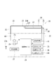
図4(A)には、タイヤ状態監視装置20の回路の構成が、バスバー30(門形端子部31及びL形端子部35)と、バスバー30以外の実装回路40とに分けて示され、図4(B)には、タイヤ状態監視装置20の回路のうち無線送信に係る部位が簡素化されて示されている。なお、図4(A)では、門形端子部31及びL形端子部35が太線で示されている。
図4(A)に示すように、ボタン電池23の正極23Pは、L形端子部35を介して制御用IC24の受電用端子Aに接続され、ボタン電池23の負極23Mは、門形端子部31の架橋部33と一方の脚部32とを介して制御用IC24のグランド用端子Bに接続されている。また、回路基板22には、例えば、比較的大きな半田層又は金属ブロックからなるグランド用導電体29が実装され、そのグランド用導電体29に制御用IC24のグランド用端子Bが接続されている。さらには、制御用IC24の出力端子Cに送信回路41の入力が接続され、その送信回路41の出力が、門形端子部31の他方の脚部32と架橋部33を介してボタン電池23の負極23Mが接続されている。また、送信回路41には、直流を遮断する図示しない直流遮断部(具体的には、コンダクタ)が備えられている。
なお、本実施形態において、図13に示すように、グランド用導電体29の手前(即ち、門形端子部31とグランド用端子Bとグランド用導電体29との共通接続部分と、グランド用導電体29との間)に、送信回路41の出力がグランド用導電体29に流れ込むことを規制するためのインダクタ28を設けてもよい。この場合、グランド用導電体29が本発明の「第1の部位」に相当すると共に、制御用IC24の出力端子Cが本発明の「第2の部位」に相当し、インダクタ28が本発明の「交流遮断部」に相当する。
これらにより、タイヤ状態監視装置20には、制御用IC24と送信回路41と一方の脚部32と架橋部33と他方の脚部32とを直列に備える交流の閉回路C1(図4(B)参照)と、制御用IC24と送信回路41と一方の脚部32と架橋部33とL形端子部35とを直列に備える交流の閉回路C2(図4(B)参照)とが構成されている。そして、制御用IC24がこれら閉回路C1,C2をループアンテナ(詳細には、微小ループアンテナ)として利用して無線送信を行う。
具体的には、タイヤ状態監視装置20は、図5に示す車両本体99に搭載された本体装置50の送信回路52から質問信号を送信され、それをタイヤ状態監視装置20の受信回路27が受信した場合、或いは、加速度センサ49で車両100の発進又は停止を検出した場合に、制御用IC24が、圧力センサ25及び温度センサ26によりタイヤ97の状態として、タイヤ97内の圧力と温度とを検出する。そして、制御用IC24が送信回路41を制御し、検出結果を高周波(例えば、300~400[MHz])の搬送波で変調して閉回路C1,C2に出力する。これにより、閉回路C1,C2がループアンテナとなって、タイヤ97の状態の検出結果が無線送信される。なお、タイヤ状態監視装置20からの無線信号が本体装置50の受信回路53で受信されると、本体装置50の制御用IC51が異常判別を行ったり、検出結果を図示しないモニタに出力したりする。また、スマートフォンに所定のアプリケーションをダウンロードしておくことで、スマートフォンでタイヤ97の状態を確認することもできる。
上記したように本実施形態のタイヤ状態監視装置20では、回路基板22から突出するバスバー30により回路基板22の実装回路40とボタン電池23との間が接続されている。そして、そのバスバー30を含む閉回路C1,C2をループアンテナとして利用してタイヤ97の状態の検出結果を無線送信するので、無線送信専用にループアンテナを備えた従来のものに比べて小型化及び低コスト化が可能になる。また、バスバー30に回路基板22の表側面22Aから突出したL形端子部35及び門形端子部31を設けてボタン電池23に接続することで、回路基板22にボタン電池23を対向配置してコンパクトな構成にすることができる。さらには、門形端子部31が、制御用IC24の出力端子Cとグランド用導電体29とを直流的に同電位にするために使用されて、有効利用されている。
[第2実施形態]
本実施形態のタイヤ状態監視装置20Vは、図6に示すように、第1実施形態のタイヤ状態監視装置20における門形端子部31に代えてL形端子部35を備え、2つのL形端子部35,35の片持ち梁部37,37でボタン電池23を挟持した構造になっている。図7(A)に示すように、一方のL形端子部35は、前記第1実施形態のタイヤ状態監視装置20と同様に、制御用IC24の受電用端子Aとボタン電池23の正極23Pとの間を接続している。門形端子部31に代わる他方のL形端子部35は、一端部がボタン電池23の負極23Mに接続され、他端部がインダクタ28を介して制御用IC24のグランド用端子Bに接続されている。また、グランド用端子Bとインダクタ28との共通接続部分に、グランド用導電体29が接続されている。さらには、インダクタ28とL形端子部35との共通接続部分に、制御用IC24の出力端子Cに接続された送信回路41の出力が接続されている。これらにより、本実施形態のタイヤ状態監視装置20Vでは、図7(B)に示すように1対のL形端子部35,35とボタン電池23とを直列に備えた閉回路C3が構成される。そして、送信回路41が、タイヤ97の状態の検出結果を高周波の搬送波で変調して閉回路C3に出力し、これにより、閉回路C3がループアンテナとなって、タイヤ97の状態の検出結果が無線送信される。
本実施形態のタイヤ状態監視装置20Vは、図6に示すように、第1実施形態のタイヤ状態監視装置20における門形端子部31に代えてL形端子部35を備え、2つのL形端子部35,35の片持ち梁部37,37でボタン電池23を挟持した構造になっている。図7(A)に示すように、一方のL形端子部35は、前記第1実施形態のタイヤ状態監視装置20と同様に、制御用IC24の受電用端子Aとボタン電池23の正極23Pとの間を接続している。門形端子部31に代わる他方のL形端子部35は、一端部がボタン電池23の負極23Mに接続され、他端部がインダクタ28を介して制御用IC24のグランド用端子Bに接続されている。また、グランド用端子Bとインダクタ28との共通接続部分に、グランド用導電体29が接続されている。さらには、インダクタ28とL形端子部35との共通接続部分に、制御用IC24の出力端子Cに接続された送信回路41の出力が接続されている。これらにより、本実施形態のタイヤ状態監視装置20Vでは、図7(B)に示すように1対のL形端子部35,35とボタン電池23とを直列に備えた閉回路C3が構成される。そして、送信回路41が、タイヤ97の状態の検出結果を高周波の搬送波で変調して閉回路C3に出力し、これにより、閉回路C3がループアンテナとなって、タイヤ97の状態の検出結果が無線送信される。
[第3実施形態]
本実施形態のタイヤ状態監視装置20Wは、図8~図10に示されている。このタイヤ状態監視装置20Wの回路基板22は、四角形の一辺に半円を合体させた形状をなしている。即ち、回路基板22は、半円部22Nと矩形部22Mとからなる。また、その半円部22Nの直径はボタン電池23の直径と略同じ大きさになっていて、ボタン電池23と半円部22Nとが同心軸上に配置された状態にバスバー30によって保持されている。
本実施形態のタイヤ状態監視装置20Wは、図8~図10に示されている。このタイヤ状態監視装置20Wの回路基板22は、四角形の一辺に半円を合体させた形状をなしている。即ち、回路基板22は、半円部22Nと矩形部22Mとからなる。また、その半円部22Nの直径はボタン電池23の直径と略同じ大きさになっていて、ボタン電池23と半円部22Nとが同心軸上に配置された状態にバスバー30によって保持されている。
バスバー30は、L形端子部35と第1の門形端子部42と第2の門形端子部45とからなる。図8に示すように、第2の門形端子部45は、回路基板22のうち半円部22Nと反対側の側辺と平行に延びた架橋部47から1対の脚部46,46を直角に曲げた構造をなし、脚部46,46が回路基板22の矩形部22Mにおける表側面22Aに固定されて架橋部47が回路基板22に対して空間を空けて対向している。
また、図9に示すように、第1の門形端子部42は、第2の門形端子部45の架橋部47と平行に延びた架橋部44から1対の脚部43,43を直角に曲げた構造をなし、脚部43,43が回路基板22の矩形部22Mにおける裏側面22Bに固定されて架橋部44が回路基板22に対して空間を空けて対向している。そして、図8に示すように、第1の門形端子部42の一方の脚部43が、回路基板22に形成されたスリット22Fを貫通して回路基板22の表側面22A側に突出し、第2の門形端子部45の一方の脚部46に繋がっている。また、図9に示すように、回路基板22からの突出量は、第1の門形端子部42より第2の門形端子部45の方が大きくなっていて、その第2の門形端子部45が突出する回路基板22の表側面22A側に制御用IC24が実装されている。なお、回路基板22の表裏の実装回路は、ビア、スルーホール等によって接続されている。
また、L形端子部35の脚部36は、回路基板22の半円部22Nにおける外縁部に配置されて裏側面22Bから突出し、その脚部36から片持ち梁部37が半円部22Nの円子の中心側に向かって延びている。そして、ボタン電池23の負極23Mが第1の門形端子部42の架橋部44に回路基板22の反対側から当接し、ボタン電池23の正極23PにL形端子部35の片持ち梁部37が当接している。即ち、第1の門形端子部42とL形端子部35とによってボタン電池23が挟持されている。
図10には、このタイヤ状態監視装置20Wの回路の構成が示されている。この図10と図4(A)とに比較して示されているように、本実施形態のタイヤ状態監視装置20Wでは、第1実施形態のタイヤ状態監視装置20のうち門形端子部31と制御用IC24のグランド用端子Bとの間に、第2の門形端子部45を介在させた構成になっている。つまり、第1の門形端子部42と第2の門形端子部45とを直列に備える閉回路C4がループアンテナとして利用される構成になっている。
このように本実施形態のタイヤ状態監視装置20Wによれば、回路基板22の表裏の一方の面から突出した第1の門形端子部42と他方の面から突出した第2の門形端子部45とを含む閉回路C4をループアンテナとして備えたことで、回路基板22の表裏における突出部分のバランスがよくなり、コンパクトな構成にすることができる。
[第4実施形態]
本実施形態のタイヤ状態監視装置20Xは、図11に示されており、回路基板22の表側面22Aに設けられた門形端子部31の架橋部33とL形端子部35の片持ち梁部37とが平行に配置されている。そして、片持ち梁部37が架橋部33の下方に位置し、それら片持ち梁部37と架橋部33との間にボタン電池23が挟持されてボタン電池23の正極23PがL形端子部35に接続される一方、ボタン電池23の負極23Mが門形端子部31に接続されている。なお、ボタン電池23は、中心から外れた位置を片持ち梁部37と架橋部33とに挟持され、その挟持された部分の反対側は、回路基板22から側方に張り出している。また、タイヤ状態監視装置20Xの回路の構成は、図4に示された第1実施形態のタイヤ状態監視装置20と同じになっている。
本実施形態のタイヤ状態監視装置20Xは、図11に示されており、回路基板22の表側面22Aに設けられた門形端子部31の架橋部33とL形端子部35の片持ち梁部37とが平行に配置されている。そして、片持ち梁部37が架橋部33の下方に位置し、それら片持ち梁部37と架橋部33との間にボタン電池23が挟持されてボタン電池23の正極23PがL形端子部35に接続される一方、ボタン電池23の負極23Mが門形端子部31に接続されている。なお、ボタン電池23は、中心から外れた位置を片持ち梁部37と架橋部33とに挟持され、その挟持された部分の反対側は、回路基板22から側方に張り出している。また、タイヤ状態監視装置20Xの回路の構成は、図4に示された第1実施形態のタイヤ状態監視装置20と同じになっている。
[第5実施形態]
本実施形態のタイヤ状態監視装置20Yは、図12に示されており、バスバー30がクランク形端子部60とL形端子部61とからなる。L形端子部61は、回路基板22の表側面22Aの一側縁部から起立してから直角に曲がって回路基板22の側方へと片持ち梁状に延びている。また、クランク形端子部60は、回路基板22の表側面22Aの一側縁部のうちクランク形端子部60から離れた位置から起立してからクランク状に曲がり、回路基板22の裏側面22B側で回路基板22の側方へと片持ち梁状に延びている。そして、回路基板22の側方位置でクランク形端子部60とL形端子部61との間にボタン電池23が挟持されている。また、タイヤ状態監視装置20Yの回路の構成は、図7に示された第2実施形態のタイヤ状態監視装置20Vと同じになっている。
本実施形態のタイヤ状態監視装置20Yは、図12に示されており、バスバー30がクランク形端子部60とL形端子部61とからなる。L形端子部61は、回路基板22の表側面22Aの一側縁部から起立してから直角に曲がって回路基板22の側方へと片持ち梁状に延びている。また、クランク形端子部60は、回路基板22の表側面22Aの一側縁部のうちクランク形端子部60から離れた位置から起立してからクランク状に曲がり、回路基板22の裏側面22B側で回路基板22の側方へと片持ち梁状に延びている。そして、回路基板22の側方位置でクランク形端子部60とL形端子部61との間にボタン電池23が挟持されている。また、タイヤ状態監視装置20Yの回路の構成は、図7に示された第2実施形態のタイヤ状態監視装置20Vと同じになっている。
[他の実施形態]
本発明は、前記実施形態に限定されるものではなく、例えば、以下に説明するような実施形態も本発明の技術的範囲に含まれ、さらに、下記以外にも要旨を逸脱しない範囲内で種々変更して実施することができる。
本発明は、前記実施形態に限定されるものではなく、例えば、以下に説明するような実施形態も本発明の技術的範囲に含まれ、さらに、下記以外にも要旨を逸脱しない範囲内で種々変更して実施することができる。
(1)前記第1実施形態のタイヤ状態監視装置20では、ボタン電池23の負極23Mが門形端子部31によって実装回路40のグランドに接続されていたが、ボタン電池23の正極23Pが実装回路40のグランドに接続された構成としてもよい。
(2)前記第1~第5の実施形態のタイヤ状態監視装置20~20Yでは、電池としてボタン電池23を備えていたが、ボタン電池以外の電池を備えていてもよい。
20,20V,20W,20X,20Y タイヤ状態監視装置
22 回路基板
22A 表側面
22B 裏側面
23 ボタン電池(電池)
28 インダクタ(交流遮断部)
29 グランド用導電体(第1の部位)
30 バスバー
31,42,45 門形端子部
32,43,46 脚部
33,44,47 架橋部
35,61 L形端子部
37 片持ち梁部
40 実装回路
41 送信回路
60 クランク形端子部
90 タイヤホイール
97 タイヤ
A 受電用端子
B グランド用端子
C 出力端子(第2の部位)
C1~C4 閉回路
22 回路基板
22A 表側面
22B 裏側面
23 ボタン電池(電池)
28 インダクタ(交流遮断部)
29 グランド用導電体(第1の部位)
30 バスバー
31,42,45 門形端子部
32,43,46 脚部
33,44,47 架橋部
35,61 L形端子部
37 片持ち梁部
40 実装回路
41 送信回路
60 クランク形端子部
90 タイヤホイール
97 タイヤ
A 受電用端子
B グランド用端子
C 出力端子(第2の部位)
C1~C4 閉回路
Claims (6)
- タイヤホイールに取り付けられ、タイヤの状態を検出して無線送信するタイヤ状態監視装置であって、
回路基板と、
前記回路基板に実装されている実装回路の電源である電池と、
前記回路基板から突出して、前記電池と前記実装回路との間を接続するバスバーと、
前記バスバーを含む閉回路をループアンテナとして利用して無線送信を行う送信回路とを備えるタイヤ状態監視装置。 - 前記バスバーには、前記回路基板の表裏の一方の面から突出した1対の脚部の間を架橋部で連絡してなる門形端子部が備えられて、前記電池の一方の電極が、前記架橋部に当接され、
前記門形端子部の前記1対の脚部と前記架橋部とを直列に備える前記閉回路が前記ループアンテナとして利用される請求項1に記載のタイヤ状態監視装置。 - 前記門形端子部は、前記実装回路における第1の部位と第2の部位とを直流的に同電位となるように接続し、前記第1の部位と前記門形端子部との間を交流的に断絶する交流遮断部が設けられている請求項2に記載のタイヤ状態監視装置。
- 前記バスバーには、前記回路基板の表裏の一方の面から突出しかつ屈曲したL形端子部が備えられ、
前記電池が、前記L形端子部のうち屈曲部分より先端側の片持ち梁部と前記架橋部との間に挟持され、
前記門形端子部の一方の前記脚部と前記架橋部と前記電池と前記L形端子部とを直列に備える前記閉回路が前記ループアンテナとして利用される請求項2又は3に記載のタイヤ状態監視装置。 - 前記回路基板の表裏の一方の面と他方の面とに第1の前記門形端子部と第2の前記門形端子部とが設けられ、前記第1の門形端子部の一方の前記脚部と前記第2の門形端子部の一方の脚部とが接続されて、前記第1の門形端子部と前記第2の門形端子部とを直列に備える前記閉回路が前記ループアンテナとして利用される請求項2乃至4の何れか1の請求項に記載のタイヤ状態監視装置。
- 前記バスバーには、前記回路基板の表裏の一方の面から突出しかつ屈曲した1対のL形端子部が備えられ、
前記電池は、前記回路基板の前記一方の面に対向配置されて、前記1対のL形端子部のうち屈曲部分より先端側の片持ち梁部同士の間に挟持され、
前記1対のL形端子部と前記電池とを含む前記閉回路が前記ループアンテナとして利用される請求項1に記載のタイヤ状態監視装置。
Priority Applications (2)
| Application Number | Priority Date | Filing Date | Title |
|---|---|---|---|
| JP2016546534A JP6545178B2 (ja) | 2016-03-28 | 2016-03-28 | タイヤ状態監視装置 |
| PCT/JP2016/059855 WO2017168501A1 (ja) | 2016-03-28 | 2016-03-28 | タイヤ状態監視装置 |
Applications Claiming Priority (1)
| Application Number | Priority Date | Filing Date | Title |
|---|---|---|---|
| PCT/JP2016/059855 WO2017168501A1 (ja) | 2016-03-28 | 2016-03-28 | タイヤ状態監視装置 |
Publications (1)
| Publication Number | Publication Date |
|---|---|
| WO2017168501A1 true WO2017168501A1 (ja) | 2017-10-05 |
Family
ID=59963628
Family Applications (1)
| Application Number | Title | Priority Date | Filing Date |
|---|---|---|---|
| PCT/JP2016/059855 Ceased WO2017168501A1 (ja) | 2016-03-28 | 2016-03-28 | タイヤ状態監視装置 |
Country Status (2)
| Country | Link |
|---|---|
| JP (1) | JP6545178B2 (ja) |
| WO (1) | WO2017168501A1 (ja) |
Citations (2)
| Publication number | Priority date | Publication date | Assignee | Title |
|---|---|---|---|---|
| JP2006074369A (ja) * | 2004-09-01 | 2006-03-16 | Pacific Ind Co Ltd | タイヤ状態監視装置の送信機及び同送信機に用いられるアンテナ |
| JP2010088098A (ja) * | 2008-09-02 | 2010-04-15 | Panasonic Corp | 計測装置及び計測装置から出力される計測値を送受信する無線装置 |
Family Cites Families (1)
| Publication number | Priority date | Publication date | Assignee | Title |
|---|---|---|---|---|
| JP3930024B2 (ja) * | 2004-02-17 | 2007-06-13 | 京セラ株式会社 | タイヤ空気圧情報送信装置及びこれを用いたタイヤ空気圧情報送信装置付きホイール |
-
2016
- 2016-03-28 JP JP2016546534A patent/JP6545178B2/ja not_active Expired - Fee Related
- 2016-03-28 WO PCT/JP2016/059855 patent/WO2017168501A1/ja not_active Ceased
Patent Citations (2)
| Publication number | Priority date | Publication date | Assignee | Title |
|---|---|---|---|---|
| JP2006074369A (ja) * | 2004-09-01 | 2006-03-16 | Pacific Ind Co Ltd | タイヤ状態監視装置の送信機及び同送信機に用いられるアンテナ |
| JP2010088098A (ja) * | 2008-09-02 | 2010-04-15 | Panasonic Corp | 計測装置及び計測装置から出力される計測値を送受信する無線装置 |
Also Published As
| Publication number | Publication date |
|---|---|
| JP6545178B2 (ja) | 2019-07-17 |
| JPWO2017168501A1 (ja) | 2018-10-04 |
Similar Documents
| Publication | Publication Date | Title |
|---|---|---|
| JP6212405B2 (ja) | 無線機 | |
| TWI619303B (zh) | 天線結構及應用該天線結構的無線通訊裝置 | |
| JP2009017284A (ja) | アンテナ装置 | |
| JP6365046B2 (ja) | アンテナ装置 | |
| JP6271480B2 (ja) | 通信装置、スマートメータ | |
| US20180151952A1 (en) | Communication Module and Communication Device Including Same | |
| JP2015106919A (ja) | 多周波アンテナモジュール | |
| JP2016136711A (ja) | アンテナ構造及びこのアンテナ構造を備える無線通信装置 | |
| WO2012076627A3 (fr) | Carte électronique ayant un connecteur externe | |
| TWI619314B (zh) | 多頻天線 | |
| CN103022637B (zh) | 一种内置天线、内置天线的移动终端及其通信方法 | |
| TWI532259B (zh) | 寬頻天線元件 | |
| US20130057452A1 (en) | High-frequency module and high-frequency device using the same | |
| TWI685143B (zh) | 行動裝置 | |
| TWI573317B (zh) | 無線通訊裝置 | |
| JP6545178B2 (ja) | タイヤ状態監視装置 | |
| JP2014110651A (ja) | 整流回路 | |
| JP2011188365A (ja) | アンテナ装置 | |
| JP2021072349A (ja) | 高周波モジュール及び通信装置 | |
| CN102956991B (zh) | 天线 | |
| TW201415709A (zh) | 天線組件及具有該天線組件之無線通訊裝置 | |
| TWI506857B (zh) | 應用於射頻檢測程序之印刷式天線模組 | |
| JP2008167098A (ja) | アンテナ装置及び該アンテナ装置を用いた携帯無線機 | |
| CN110690554A (zh) | 天线结构及具有该天线结构的无线通信装置 | |
| JP2014220739A (ja) | プリント基板ダイポールアンテナ |
Legal Events
| Date | Code | Title | Description |
|---|---|---|---|
| ENP | Entry into the national phase |
Ref document number: 2016546534 Country of ref document: JP Kind code of ref document: A |
|
| NENP | Non-entry into the national phase |
Ref country code: DE |
|
| 121 | Ep: the epo has been informed by wipo that ep was designated in this application |
Ref document number: 16896721 Country of ref document: EP Kind code of ref document: A1 |
|
| 122 | Ep: pct application non-entry in european phase |
Ref document number: 16896721 Country of ref document: EP Kind code of ref document: A1 |