WO2017164271A1 - 金属回収装置 - Google Patents
金属回収装置 Download PDFInfo
- Publication number
- WO2017164271A1 WO2017164271A1 PCT/JP2017/011596 JP2017011596W WO2017164271A1 WO 2017164271 A1 WO2017164271 A1 WO 2017164271A1 JP 2017011596 W JP2017011596 W JP 2017011596W WO 2017164271 A1 WO2017164271 A1 WO 2017164271A1
- Authority
- WO
- WIPO (PCT)
- Prior art keywords
- container
- cathode
- metal
- activated carbon
- anode
- Prior art date
- Legal status (The legal status is an assumption and is not a legal conclusion. Google has not performed a legal analysis and makes no representation as to the accuracy of the status listed.)
- Ceased
Links
Images



Classifications
-
- C—CHEMISTRY; METALLURGY
- C02—TREATMENT OF WATER, WASTE WATER, SEWAGE, OR SLUDGE
- C02F—TREATMENT OF WATER, WASTE WATER, SEWAGE, OR SLUDGE
- C02F1/00—Treatment of water, waste water, or sewage
- C02F1/28—Treatment of water, waste water, or sewage by sorption
-
- C—CHEMISTRY; METALLURGY
- C02—TREATMENT OF WATER, WASTE WATER, SEWAGE, OR SLUDGE
- C02F—TREATMENT OF WATER, WASTE WATER, SEWAGE, OR SLUDGE
- C02F1/00—Treatment of water, waste water, or sewage
- C02F1/46—Treatment of water, waste water, or sewage by electrochemical methods
- C02F1/461—Treatment of water, waste water, or sewage by electrochemical methods by electrolysis
-
- C—CHEMISTRY; METALLURGY
- C25—ELECTROLYTIC OR ELECTROPHORETIC PROCESSES; APPARATUS THEREFOR
- C25C—PROCESSES FOR THE ELECTROLYTIC PRODUCTION, RECOVERY OR REFINING OF METALS; APPARATUS THEREFOR
- C25C1/00—Electrolytic production, recovery or refining of metals by electrolysis of solutions
- C25C1/20—Electrolytic production, recovery or refining of metals by electrolysis of solutions of noble metals
-
- C—CHEMISTRY; METALLURGY
- C25—ELECTROLYTIC OR ELECTROPHORETIC PROCESSES; APPARATUS THEREFOR
- C25C—PROCESSES FOR THE ELECTROLYTIC PRODUCTION, RECOVERY OR REFINING OF METALS; APPARATUS THEREFOR
- C25C7/00—Constructional parts, or assemblies thereof, of cells; Servicing or operating of cells
-
- C—CHEMISTRY; METALLURGY
- C25—ELECTROLYTIC OR ELECTROPHORETIC PROCESSES; APPARATUS THEREFOR
- C25C—PROCESSES FOR THE ELECTROLYTIC PRODUCTION, RECOVERY OR REFINING OF METALS; APPARATUS THEREFOR
- C25C7/00—Constructional parts, or assemblies thereof, of cells; Servicing or operating of cells
- C25C7/02—Electrodes; Connections thereof
Definitions
- the present invention relates to a recovery device for recovering metal from a waste liquid containing metal by an electrolytic method.
- an electrolytic (reduction) method is generally used as a means for recovering noble metal remaining in various waste liquids such as a noble metal plating solution.
- a waste liquid is introduced into an electrolytic cell, an insoluble anode and a cathode are immersed in the electrolytic tank, and a metal ion in the liquid is reduced and precipitated by energization.
- Patent Document 1 and Patent Document 2 disclose metal recovery devices.
- the metal recovery device disclosed in Patent Document 1 is a cylindrical container that constitutes an electrolytic cell, and a pipe-shaped container that is disposed at the center of the container and has an opening at the bottom so that waste liquid flows from the container top to the container bottom.
- a metal recovery device comprising an anode and a cylindrical cathode disposed along the inner periphery of the container, and a first tube in a net or lath shape that is electrically connected to the cathode on the inner periphery of the cathode The body is placed.
- a noble metal recovery device disclosed in Patent Document 2 includes a cylindrical metal container that constitutes an electrolytic cell, an insulating lid body that has a waste liquid outlet that can be hermetically sealed and removed, and an insulating lid body.
- a pipe-shaped anode that passes through the center and circulates the waste liquid from the top to the bottom, a cylindrical expander cathode that is disposed along the inner periphery of the metal container, and an outer periphery of the pipe-shaped anode.
- a noble metal recovery device including a cylindrical expander anode.
- the upper part of the expander cathode is connected and fixed to the upper shoulder of the metal container in an inverted L-shaped cross section
- the lower part of the expander cathode is connected and fixed to the bottom of the metal container
- both ends of the expander anode are pipes Connected and fixed in a U-shaped cross section.
- the technology disclosed in the above-mentioned patent document is advantageous for dissolution during purification of recovered materials by suppressing the amount of precipitation due to current anomalies, the variation in precipitated particles, and the short-circuit failure due to the abnormal precipitation of noble metals resulting from current concentration. It aims to deposit good uniform noble metals stably.
- an object of the present invention is to provide a metal recovery apparatus for recovering all metals including precious metals in a highly efficient and stable manner.
- the metal recovery device of the present invention is a metal recovery device for recovering metal in an aqueous solution, and is a container constituting an electrolytic cell, an anode disposed inside the container, and a cathode disposed inside the container.
- the activated carbon molded body is obtained by molding activated carbon having a BET specific surface area of 100 to 5000 m 2 / g calculated by a nitrogen adsorption method.
- the activated carbon molded body is formed into a filter shape.
- the container is a cylindrical container
- the anode is a rod-shaped body arranged to extend in the longitudinal direction of the cylindrical container
- the cathode surrounds the anode. It is the cylindrical body arrange
- the container is a box-shaped container
- the anode is a plate-shaped body disposed inside the box-shaped container
- the cathode is disposed so as to face the anode. Plate-shaped body.
- the metal recovery apparatus of the present invention it is possible to dramatically improve the recovery efficiency by using an activated carbon molded body having a large specific surface area as the cathode material. Further, by using activated carbon having excellent performance for metal adsorption in the activated carbon molded body as the cathode, it is possible to achieve excellent recovery characteristics due to the combined action of adsorption and electrolysis.
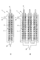
- FIG. 1 is a schematic cross-sectional view showing an embodiment of the metal recovery apparatus of the present invention, (a) is a cross-sectional view taken along line AA in FIG. 2, and (b) is a cross-sectional view taken along line B-- in FIG. Sectional drawing along a B line.
- FIG. 2 is an exploded perspective view of a part of the metal recovery apparatus according to the embodiment.
- FIG. 3 is a conceptual diagram of a metal recovery system using a metal recovery device.
- FIG. 4 is a schematic cross-sectional view showing another embodiment of the metal recovery apparatus of the present invention, (a) is an embodiment in which FIG.
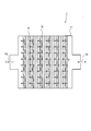
- FIG. 5 is a schematic cross-sectional view showing still another embodiment of the metal recovery apparatus of the present invention, in which a plurality of plate-like anodes and cathodes are arranged inside a box-like container.
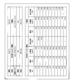
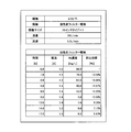
- FIG. 6 is a table showing the results of the Pd waste liquid recovery test, and shows the results of both the apparatus using the activated carbon filter of the embodiment of the present invention as the cathode and the apparatus using the conventional Ti electrode as the cathode.
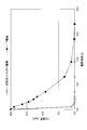
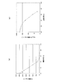
- FIG. 7 is a graph corresponding to the table of FIG.
- FIG. 10 is a graph corresponding to the table of FIG. 9, (a) is a graph in which the vertical axis indicates Rh concentration [mg / L], and (b) is a graph in which the vertical axis indicates log 10 [Rh concentration [mg / L]. L]].
- FIG. 1 is a schematic cross-sectional view showing an embodiment of the metal recovery apparatus of the present invention
- FIG. 1 (a) is a cross-sectional view taken along the line AA in FIG. 2
- FIG. 3 is a cross-sectional view taken along line BB in FIG.
- FIG. 2 is an exploded perspective view of a part of the embodiment.
- the metal recovery apparatus 1 of the embodiment is made of a resin and has a cylindrical container 11 that constitutes an electrolytic cell, and an outer shape of the upper cover 12 and a lower cover 13 that seals the upper and lower ends of the container 11.
- the A support base 14 is formed in the container 11 and immediately above the lower lid 13. Further, a rod-like anode (anode) 15 and a cylindrical cathode (cathode) 16 are arranged inside the container 11 while being supported by an upper support plate 17 and a lower support plate 18.
- the lower support plate 18 is disposed on the support base 14, and the anode 15 is supported by these members while penetrating the lower lid 13, the support base 14, and the lower support plate 18.
- a metal cathode terminal 19 is fixed to the cathode 16, and the cathode terminal 19 is supported by these members while penetrating the upper support plate 17 and the upper lid 12.
- FIG. 1B shows the cathode terminal 19 which does not appear originally.
- the upper lid 12 is formed with an introduction path 12a for introducing an aqueous solution (waste liquid) containing a metal to be collected into a container 11 serving as an electrolytic tank, and a discharge path 12b for discharging the treated waste liquid from the container 11.
- the waste liquid is introduced from the outside of the container 11 into the introduction path 12a as indicated by an arrow A, and is processed in the process of passing through the cathode 16 toward the anode 15 as indicated by an arrow B. Further, as shown by the arrow C, the processed waste liquid is discharged from the discharge path 12b to the outside of the container 11.
- the container 11 is a cylindrical container
- the anode 15 is a rod-shaped body arranged so as to extend in the longitudinal direction of the cylindrical container.
- the anode 15 is preferably an insoluble material, and as the material, at least the surface is preferably made of a platinum group metal, alloy or oxide. Further, a valve metal such as titanium plated with platinum or a platinum alloy or coated with iridium oxide or ruthenium oxide is more preferable in terms of cost and durability.
- the cathode 16 disposed adjacent to the anode 15 is formed of an activated carbon molded body made of activated carbon.
- the activated carbon molded body is an activated carbon filter formed in a filter shape, and is a hollow cylindrical body arranged so as to surround the periphery of the anode 15.
- the rod-shaped anode 15 is disposed in the cylindrical space at the center of the cathode 16.
- FIG. 1 only the anode 15 and the cathode 16 are hatched for the sake of easy understanding (the same applies to other drawings).
- the activated carbon used in the activated carbon molding of the present invention can be selected from the range where the BET specific surface area calculated by the nitrogen adsorption method is about 100 to 5000 m 2 / g, for example, 300 to 4000 m 2 / g, preferably 500 to 3000 m. It is about 2 / g. If the specific surface area is too small, the recovery efficiency decreases due to a decrease in the volume used for electrodeposition.
- the shape of the activated carbon used in the activated carbon molded body of the present invention is not particularly limited, and may be granular, fibrous, or indefinite, but is usually granular or fibrous.
- the average primary particle size of the granular activated carbon may be, for example, about 1 ⁇ m to 5 mm (particularly 10 ⁇ m to 2 mm).
- the average fiber diameter of the fibrous activated carbon is, for example, 1 to 500 ⁇ m, preferably about 2 to 300 ⁇ m, and particularly about 5 to 50 ⁇ m.
- the activated carbon molded body used in the present invention only needs to contain the activated carbon.
- it may be a molded body of a mixture including the activated carbon and a binder.
- the molding by the simple substance of activated carbon fiber may be sufficient.
- the specific surface area of the activated carbon molding can be selected from a range of about 500 to 2500 m 2 / g, for example.
- the binder only needs to be able to fix the activated carbon to the molded body.
- the binder may be a binder for binding the activated carbon to form the molded body, or a binder for supporting the activated carbon on the base material constituting the molded body. May be.
- the binder fibrillated fibers and / or thermoplastic binder particles are usually used.
- FIG. 3 shows a metal recovery system 100 including the metal recovery apparatus 1, and the metal recovery system 100 includes a metal recovery apparatus 1, a recovery waste liquid tank 20, a pump 21, a filter 22, and a power supply 30.
- the waste liquid is sent from the recovery waste liquid tank 20 containing the metal-containing waste liquid by the pump 21 or the like, and the sent waste liquid is introduced into the introduction path 12a of the metal recovery apparatus 1 (arrow in FIG. 1). A).
- the waste liquid flows through the container 11 from the top to the bottom, and passes through the cathode 16 of the activated carbon filter toward the anode 15 (arrow B in FIG. 1).
- the power source 30 is electrically connected to the anode 15 via the anode 15 and the cathode terminal 19, and a voltage is applied between the anode 15 and the cathode 16 to cause electrolysis.
- the metal in the waste liquid is adsorbed by the cathode 16 and collected.
- the waste liquid thus treated flows through the container 11 from the bottom to the top and is discharged from the discharge path 12b (arrow C in FIG. 1).
- the discharged waste liquid is returned to the recovered waste liquid tank 20 through the filter 22, and the returned waste liquid is circulated.
- the space velocity SV of the recovered waste liquid in the metal recovery apparatus 1 varies depending on the metal ion species in the target waste liquid, electrolysis conditions, etc., but the space velocity SV is not particularly limited.
- the space velocity SV is preferably, for example, 10 to 10,000 / h, and more preferably 50 to 5,000 / h. The higher the space velocity SV, the larger the amount of treatment, but the shorter the contact time with the cathode 16, the lower the metal recovery rate.
- the space velocity is relatively high, for example, when the aqueous solution is passed through the activated carbon molded body under a relatively high speed condition of a space velocity of 500 / h or more, A relatively high recovery rate can be maintained. From this, even if the space velocity SV is within the above range, a sufficiently excellent recovery rate can be realized.
- the space velocity SV can be measured by a known method.
- the space velocity SV is calculated, for example, by measuring the flow rate and dividing the measured flow rate by the volume of the activated carbon molded body that is the cathode 16.
- the current density of the cathode 16 is preferably 1.0 ⁇ 10 ⁇ 8 to 1.0 ⁇ 10 ⁇ 6 A / dm 2 .
- the method for desorbing the metal electrodeposited on the cathode 16 is not particularly limited.
- the activated carbon molded body on which the metal is electrodeposited is directly dissociated as a metal salt with an inorganic strong acid or alkaline solution and reduced, and then recovered as a metal
- Examples include a method in which an activated carbon molded body electrodeposited with carbon is burned to be ashed, extracted from the obtained ashed product with a strong inorganic acid or the like, and reduced.
- recovering as an alloy is mentioned.
- FIG. 4 (a) and 4 (b) show a metal recovery apparatus 1 of another embodiment.
- the container 11 is a cylindrical container
- the anode Reference numeral 15 denotes a rod-like body arranged inside the cylindrical container, and a cylindrical body arranged so that the cathode 16 faces the anode 15.
- the sent waste liquid is introduced into the introduction path 12a of the metal recovery apparatus 1 (arrow A).
- the waste liquid flows through the container 11 in the lateral direction, and passes through the cathode 16 of the activated carbon filter toward the anode 15 (arrow B). In this process, the metal in the waste liquid is adsorbed by the cathode 16 and collected.
- the waste liquid thus treated further flows in the container 11 in the lateral direction and is discharged from the discharge path 12b (arrow C).
- FIG. 5 shows a metal recovery apparatus 1 of still another embodiment.
- the container 11 is a box-shaped container
- the anode 15 is a plate-shaped body disposed inside the box-shaped container
- the cathode 16 is a plate-shaped body disposed so as to face the anode 15.
- the plurality of anodes 15 and cathodes 16 are alternately arranged along the flow direction of the waste liquid.
- the sent waste liquid is introduced into the introduction path 12a of the metal recovery apparatus 1 (arrow A).
- the waste liquid flows through the container 11 in the lateral direction, and passes through the cathode 16 of the activated carbon filter toward the anode 15 (arrow B).
- the metal in the waste liquid is adsorbed by the cathode 16 and collected.
- a gap or the like (not shown) is provided in the anode 15 and the container 11 so that the waste liquid can pass through.
- the anode 15 may also be provided with a hole for passing the waste liquid. Then, the waste liquid processed by passing through all the anodes 15 and the cathodes 16 is discharged from the discharge path 12b (arrow C).
- FIG. 6 is a table showing the recovery test results of the Pd waste liquid. Both the apparatus using the activated carbon filter of the embodiment of the present invention as a cathode (activated carbon filter electrode) and the apparatus using a conventional Ti electrode as a cathode. It is a table
- the target liquid is a Pd-containing alkaline liquid, the liquid volume is 40 L, the flow rate is 20 L / min, and the current value is about 3.0 A.
- FIG. 7 is a graph corresponding to the table of FIG. 6, in which the vertical axis represents Pd concentration [mg / L].
- FIG. 8 is a graph corresponding to the table of FIG. 6, and the vertical axis is log 10 [Pd concentration [mg / L]].
- the concentration of Pd in the recovered liquid decreases more rapidly with the passage of electrolysis time than when using the conventional Ti electrode, and more It is understood that Pd can be efficiently recovered.
- the table in FIG. 9 shows the results of the Rh waste liquid recovery test, and the results of the apparatus using the activated carbon filter of the present invention as the cathode.
- Test conditions are an Rh concentration of 100 mg / L, a liquid volume of 20 L, and a flow rate of 200 L / hr.
- the graph of FIG. 10 corresponds to the table of FIG. 9, FIG. 10A shows the Rh concentration [mg / L] on the vertical axis, and FIG. 10B shows the vertical axis of FIG. Logarithmic notation, that is, log 10 [Rh concentration [mg / L]]. From the table in FIG. 9 and the graph in FIG. 10, it is understood that by using the activated carbon filter of the embodiment as the cathode, the concentration of Rh in the recovered liquid decreases with the passage of electrolysis time, and Rh can be reliably recovered.
- the entire cathode 16 is composed of an activated carbon filter, and the area of the cathode 16 is extremely large. Therefore, the adhesion efficiency and deposition efficiency of the metal in the aqueous solution to the cathode 16 are high.
- the metal can be electrodeposited inside the activated carbon filter constituting the cathode 16, it is possible to prevent the metal fine particles from floating in the waste liquid. That is, by using activated carbon having a performance excellent in metal adsorption as the material of the cathode 16, excellent recovery characteristics due to a combined action of adsorption and electrolysis can be achieved.
- the metal recovery apparatus has excellent performance for recovering all metals, but particularly has excellent performance for recovering precious metals, especially poorly soluble platinum group metals such as Pt, Pd, Rh, and Ir.
- the effect as mentioned above can be exhibited by constituting at least a part of the cathode 16 with the activated carbon molded body and the activated carbon filter of the present embodiment.
- the cathode and metal filter which were conventionally separate members, are formed of an integral member (cathode of activated carbon molding). Therefore, the replacement of the cathode and the replacement of the filter cartridge can be performed in one process, and maintenance and replacement are facilitated.
Landscapes
- Chemical & Material Sciences (AREA)
- Engineering & Computer Science (AREA)
- Organic Chemistry (AREA)
- Electrochemistry (AREA)
- Chemical Kinetics & Catalysis (AREA)
- Materials Engineering (AREA)
- Metallurgy (AREA)
- Life Sciences & Earth Sciences (AREA)
- Hydrology & Water Resources (AREA)
- Environmental & Geological Engineering (AREA)
- Water Supply & Treatment (AREA)
- General Chemical & Material Sciences (AREA)
- Electrolytic Production Of Metals (AREA)
- Water Treatment By Electricity Or Magnetism (AREA)
- Water Treatment By Sorption (AREA)
Abstract
水溶液中の金属を回収する金属回収装置であって、電解槽を構成する容器(11)と、容器(11)の内部に配置された陽極(15)と、容器(11)の内部に配置された陰極(16)と、を備え、陰極(16)が活性炭成型体により構成され、活性炭成型体は、窒素吸着法により算出されるBET比表面積が100~5000m2/gである活性炭を成型したものである、金属回収装置(1)。
Description
本発明は、金属を含む廃液から金属を電解法により回収するための回収装置に関する。
例えば、貴金属めっき液といった各種廃液中に残留する貴金属を回収する手段として、電解(還元)法が一般的に用いられている。この電解法による貴金属回収装置では、電解槽中に廃液を導入し、これに不溶性陽極及び陰極を浸漬させて通電することで液中の金属イオンを還元析出させるものである。
特許文献1および特許文献2は、金属の回収装置を開示している。特許文献1に開示の金属回収装置は、電解槽を構成する円筒状の容器と、容器の中心に配置され、廃液を容器上部から容器底部へと流通させるように底部に開口を有するパイプ状の陽極と、容器の内周に沿って配置される筒状の陰極と、を備える金属回収装置であり、陰極の内周に、陰極と電気的に接続される網状又はラス状の第1の筒体が配置されている。
特許文献2に開示の貴金属回収装置は、電解槽を構成する円筒状の金属製容器と、金属製容器を密閉し取外し可能な、廃液流出口を有する絶縁性蓋体と、絶縁性蓋体の中心を貫通し、廃液を上部から底部へと流通させるパイプ状陽極と、金属製容器の内周に沿って配置される筒状のエキスパンダ陰極と、パイプ状陽極の外周に沿って配置される筒状のエキスパンダ陽極と、を備える貴金属回収装置である。エキスパンダ陰極の上部は金属製容器の上肩部と断面逆L字形に接続固定されており、エキスパンダ陰極の下部は金属製容器の底部と接続固定されており、エキスパンダ陽極の両端はパイプ状陽極と断面コの字形に接続固定されている。
上記特許文献に開示の技術は、電流異常による析出量や析出粒子のばらつきや、電流集中に由来する貴金属の異常析出による短絡不良を抑制することにより、回収物の精製の際の溶解に都合の良い均一な貴金属を安定的に析出させることを図っている。
しかしながら、上記特許文献に記載の技術においても、実用上十分な貴金属の回収効率を達成することが困難であり、一層の回収効率の向上が望まれている。
そこで、本発明は、貴金属を含む金属全般を高効率かつ安定的に回収するための金属回収装置を提供することを目的とする。
本発明の金属回収装置は、水溶液中の金属を回収する金属回収装置であって、電解槽を構成する容器と、前記容器の内部に配置された陽極と、前記容器の内部に配置された陰極と、を備え、前記陰極が活性炭成型体により構成され、前記活性炭成型体は、窒素吸着法により算出されるBET比表面積が100~5000m2/gである活性炭を成型したものである。
本発明の実施態様の一例として、例えば、前記活性炭成型体がフィルター状に成形されたものである。
本発明の実施態様の一例として、例えば、前記容器が筒状容器であり、前記陽極が前記筒状容器の長手方向に延びるように配置された棒状体であり、前記陰極が前記陽極の周囲を取り囲むように配置された筒状体である。
本発明の実施態様の一例として、例えば、前記容器が箱状容器であり、前記陽極が前記箱状容器の内部に配置された板状体であり、前記陰極が前記陽極に対面するように配置された板状体である。
本発明の金属回収装置によれば、陰極の材料に比表面積の大きな活性炭成型体を用いる事で、回収効率を飛躍的に向上させる事が出来る。また、陰極である活性炭成型体に金属の吸着に優れた性能を持つ活性炭を利用する事により吸着と電解の複合的作用による優れた回収特性を達成することができる。
以下、本発明の金属回収装置の実施の形態を、図面を用いて説明する。図1は、本発明の金属回収装置の一実施形態を示す断面概略図であり、図1(a)は図2におけるA-A線に沿った断面図であり、図1(b)は図2におけるB-B線に沿った断面図である。図2は、同実施形態の一部の分解斜視図である。
実施形態の金属回収装置1は、樹脂製であって電解槽を構成する筒状の容器11と、容器11の上端および下端を封止する上蓋12と下蓋13とから、その外形が構成される。容器11の内部であって、下蓋13の直上には支持台14が形成されている。さらに、棒状の陽極(アノード)15および円筒状の陰極(カソード)16が、上支持板17および下支持板18により支持されつつ、容器11の内部に配置されている。
下支持板18は支持台14の上に配置され、陽極15は下蓋13、支持台14、下支持板18を貫通しつつ、これらの部材によって支持されている。一方、陰極16には金属製の陰極端子19が固定され、この陰極端子19は上支持板17および上蓋12を貫通しつつ、これらの部材によって支持されている。構成を容易に把握するため、図1(b)では、本来表れない陰極端子19を示している。
上蓋12には、回収対象の金属を含む水溶液(廃液)を電解槽である容器11に導入する導入路12aおよび処理済みの廃液を容器11から排出する排出路12bが形成されている。廃液は容器11の外部から矢印Aで示すように導入路12aに導入され、矢印Bで示すように陰極16を通過して陽極15に向かう過程で処理される。さらに処理済みの廃液は、矢印Cで示すように、排出路12bから容器11の外部へ排出される。
本実施形態において、容器11は筒状容器であり、陽極15は筒状容器の長手方向に延びるように配置された棒状体である。陽極15は、不溶性の材料が好ましくその材質としては、少なくとも表面が白金族の金属、合金または酸化物よりなるものが好ましい。更に、チタン等のバルブ金属に白金または白金合金をめっきしたものあるいは酸化イリジウムまたは酸化ルテニウムを被覆したものがコスト的にも耐久性においてもより好ましい。
本実施形態において、陽極15に隣接して配置された陰極16は、活性炭を材料とした活性炭成型体により形成される。特に本実施形態では、この活性炭成型体がフィルター状に成形された活性炭フィルターの態様をとり、陽極15の周囲を取り囲むように配置された中空の筒状体である。言い換えると、棒状体の陽極15が、陰極16の中心の筒状空間に配置されている。尚、図1では、理解を容易にするため、陽極15および陰極16にのみハッチングが施されている(他の図でも同様)。
本発明の活性炭成型体に使用する活性炭は、窒素吸着法により算出されるBET比表面積が100~5000m2/g程度の範囲から選択でき、例えば、300~4000m2/g、好ましくは500~3000m2/g程度である。比表面積が小さすぎると、電着に供する容積の低下により回収効率が低下し、大きすぎると、嵩密度の低下により電気抵抗が高くなり、効率が低下する。
本発明の活性炭成型体に使用する活性炭の形状は、特に限定されず、粒状、繊維状、不定形状などであってもよいが、通常、粒状又は繊維状である。粒状活性炭の平均一次粒径は、例えば、1μm~5mm(特に10μm~2mm)程度であってもよい。繊維状活性炭の平均繊維径は、例えば、1~500μm、好ましくは2~300μm程度であり、特に5~50μm程度であってもよい。
本発明に使用する活性炭成型体は、前記活性炭を含んでいればよく、例えば、前記活性炭とバインダとを含む混合物の成型体であってもよい。また、活性炭繊維の単体による成型体であってもよい。また、活性炭成型体の比表面積は、例えば500~2500m2/g程度の範囲から選択できる。
バインダは、活性炭を成型体に固定できればよく、例えば、活性炭を結合して成型体を形成するためのバインダであってもよく、成型体を構成する基材に活性炭を担持させるためのバインダであってもよい。バインダとしては、通常、フィブリル化繊維及び/又は熱可塑性バインダ粒子が使用される。
次に、金属回収装置1を用いた金属回収システムおよび金属回収方法について、図3を用いて説明する。図3は金属回収装置1を含む金属回収システム100を示し、金属回収システム100は、金属回収装置1と、回収廃液槽20と、ポンプ21と、フィルター22と、電源30とを含む。金属回収方法において、金属を含む廃液を収容する回収廃液槽20から廃液をポンプ21などで送液し、送液された廃液が金属回収装置1の導入路12aに導入される(図1の矢印A)。廃液は容器11を上部から底部へと流通しつつ、活性炭フィルターの陰極16を通過して陽極15に向かう(図1の矢印B)。電源30は陽極15と、陰極端子19を介して陰極16に電気的に接続されており、陽極15と陰極16の間に電圧が印加されて電気分解が生ずる。この過程で、廃液中の金属が陰極16により吸着され、回収される。このようにして処理された廃液は、容器11を底部から上部へ流通し、排出路12bから排出される(図1の矢印C)。排出された廃液は、フィルター22を通して回収廃液槽20へ戻され、その戻された廃液が循環される。
本発明の金属回収装置において、回収廃液の金属回収装置1内の空間速度SVは対象となる廃液中の金属イオン種、電解条件等により異なるが、空間速度SVは、特に限定されない。空間速度SVとしては、例えば、10~10,000/hであることが好ましく、50~5,000/hであることがより好ましい。空間速度SVは、高いほど処理量が増えるが、陰極16との接触時間が短くなるので、金属の回収率が低下する傾向がある。本実施形態に係る回収方法では、比較的速い空間速度であっても、例えば、空間速度500/h以上という比較的高速な条件下で、活性炭成型体に水溶液を通過させる場合であっても、比較的高い回収率が維持できる。このことから、空間速度SVが上記範囲内であっても、充分に優れた回収率を実現できる。
なお、空間速度SVは、公知の方法で測定することができる。空間速度SVは、例えば、流量を測定し、その測定した流量を、陰極16である活性炭成型体の体積で除することによって、算出される。また、陰極16の電流密度は1.0×10⁻⁸~1.0×10⁻⁶A/dm2で行うことが望ましい。
陰極16に電着した金属を脱着する方法としては、特に限定されない。この脱着方法としては、具体的には、金属が電着された活性炭成型体を、直接、無機強酸やアルカリ溶液等で金属塩として解離させ、還元することにより、金属として回収する方法や、金属を電着した活性炭成型体を燃焼させて灰化し、得られた灰化物から無機強酸等で抽出し、還元する方法等が挙げられる。また、燃焼させて得られた灰化物を銅等の金属と同時に熔融させ、合金として回収する方法が挙げられる。
図4(a)および図4(b)は他の実施形態の金属回収装置1を示し、図4(a)および図4(b)の双方において、容器11が筒状の容器であり、陽極15が筒状の容器の内部に配置された棒状体であり、陰極16が陽極15に対面するように配置された筒状体である。図4(a)において、送液された廃液が金属回収装置1の導入路12aに導入される(矢印A)。廃液は容器11を横方向に流通しつつ、活性炭フィルターの陰極16を通過して陽極15に向かう(矢印B)。この過程で、廃液中の金属が陰極16により吸着され、回収される。このようにして処理された廃液は、さらに容器11内を横方向へ流通し、排出路12bから排出される(矢印C)。図4(b)も同様であるが、図4(a)における陽極15と陰極16の組み合わせが3組、容器11の上下または水平方向に設けられている。
図5はさらに他の実施形態の金属回収装置1を示す。本実施形態においては容器11が箱状容器であり、陽極15が箱状容器の内部に配置された板状体であり、陰極16が陽極15に対面するように配置された板状体である。そして本実施形態においては、複数の陽極15と陰極16が、廃液の流通方向にそって交互に配置されている。送液された廃液が金属回収装置1の導入路12aに導入される(矢印A)。廃液は容器11を横方向に流通しつつ、活性炭フィルターの陰極16を通過して陽極15に向かう(矢印B)。この過程で、廃液中の金属が陰極16により吸着され、回収される。陽極15と容器11には図示せぬ隙間などが設けられており、廃液は通過することができる。陽極15も廃液の通過用の穴を設けてもよい。そして総ての陽極15と陰極16と通過して処理された廃液は、排出路12bから排出される(矢印C)。
図6は、Pd廃液の回収試験結果を示す表であり、本発明の実施形態の活性炭フィルターを陰極(活性炭フィルター電極)として用いた装置と、従来型のTi電極を陰極として用いた装置の双方の結果を示す表である。対象液はPd含有アルカリ液であり、液量は40L、流量は20L/min、電流値は約3.0Aである。また、図7は、図6の表に対応したグラフであり、縦軸をPd濃度[mg/L]としたグラフである。図8は、図6の表に対応したグラフであり、縦軸をlog10[Pd濃度[mg/L]]としたグラフである。
図6~図8より、実施形態の活性炭フィルターを陰極に用いることにより、従来のTi電極を用いた場合に比べて、電解時間の経過とともに回収液中のPdの濃度がより速く減少し、より効率的にPdを回収できることが理解される。
図9の表は、Rh廃液の回収試験結果であり、本発明の活性炭フィルターを陰極に用いた装置の結果である。試験条件(電解条件)は、Rh濃度100mg/L、液量20L、流量200L/hrである。図10のグラフは図9の表に対応したものであり、図10(a)は縦軸をRh濃度[mg/L]とし、図10(b)は、図10(a)の縦軸を対数標記にしたもの、すなわち、log10[Rh濃度[mg/L]]としたものである。図9の表および図10のグラフから、実施形態の活性炭フィルターを陰極に用いることにより、電解時間の経過とともに回収液中のRhの濃度が減少し、確実にRhを回収できることが理解される。
これまでの金属回収においては、TiやSUS等の金属を電極として電解回収するケースが一般的である。また、カーボン粒子等の流動床を電極として回収するケースも知られている。しかしながら、金属の中でも特に白金族金属は、電解回収した後、王水、シアン化アルカリ等の薬液で溶解し、電極から剥離することが困難である。また、これらの金属は電極への密着性が悪く、金属微粒子が廃液中に浮遊し、配管内をめっきする等の不具合を起こすことがある。
本実施形態では、陰極16の全体が活性炭フィルターにより構成されており、陰極16の面積が極めて大きくなっている。したがって、水溶液中の金属の陰極16への密着効率、析出効率が高い。また、陰極16を構成する活性炭フィルターの内部に金属を電着させることができるため、金属微粒子が廃液中に浮遊することも防止できる。すなわち、陰極16の材料に、金属の吸着に優れた性能を持つ活性炭を利用することにより、吸着と電解の複合的作用による優れた回収特性を達成することができる。さらに、金属の吸着回収後、陰極16を焼成灰化すれば、回収精製が容易となる。本実施形態の金属回収装置は、金属全般の回収に優れた性能を有するが、特に貴金属、とりわけPt、Pd、Rh、Ir等の難溶解性の白金族金属の回収に優れた性能を有する。なお、陰極16の少なくとも一部を本実施形態の活性炭成型体、活性炭フィルターにより構成することにより、上述したような効果を発揮し得る。
また、本実施形態では、従来は別々の部材であった陰極と金属のフィルター(フィルターカートリッジ)が、一体の部材(活性炭成型体の陰極)で構成されていると把握される。よって、陰極の交換とフィルターカートリッジの交換を一つのプロセスで行うことが可能となり、保守交換が容易となる。
本出願は、2016年3月24日出願の日本特許出願、特願2016-060239に基づくものであり、その内容はここに参照として取り込まれる。
1 金属回収装置
11 容器
12 上蓋
13 下蓋
14 支持台
15 陽極
16 陰極(活性炭成型体、活性炭フィルター)
17 上支持板
18 下支持板
19 陰極端子
20 回収廃液槽
21 ポンプ
22 フィルター
30 電源
100 金属回収システム
11 容器
12 上蓋
13 下蓋
14 支持台
15 陽極
16 陰極(活性炭成型体、活性炭フィルター)
17 上支持板
18 下支持板
19 陰極端子
20 回収廃液槽
21 ポンプ
22 フィルター
30 電源
100 金属回収システム
Claims (5)
- 水溶液中の金属を回収する金属回収装置であって、
電解槽を構成する容器と、
前記容器の内部に配置された陽極と、
前記容器の内部に配置された陰極と、を備え、
前記陰極が活性炭成型体により構成され、
前記活性炭成型体は、窒素吸着法により算出されるBET比表面積が100~5000m2/gである活性炭を成型したものである、
金属回収装置。 - 前記活性炭成型体がフィルター状に成形されたものである、請求項1に記載の金属回収装置。
- 回収対象の金属が貴金属である、請求項1に記載の金属回収装置。
- 前記容器が筒状容器であり、
前記陽極が前記筒状容器の長手方向に延びるように配置された棒状体であり、
前記陰極が前記陽極の周囲を取り囲むように配置された筒状体である、請求項1に記載の金属回収装置。 - 前記容器が箱状容器であり、
前記陽極が前記箱状容器の内部に配置された板状体であり、
前記陰極が前記陽極に対面するように配置された板状体である、請求項1に記載の金属回収装置。
Applications Claiming Priority (2)
| Application Number | Priority Date | Filing Date | Title |
|---|---|---|---|
| JP2016060239A JP2017172007A (ja) | 2016-03-24 | 2016-03-24 | 金属回収装置 |
| JP2016-060239 | 2016-03-24 |
Publications (1)
| Publication Number | Publication Date |
|---|---|
| WO2017164271A1 true WO2017164271A1 (ja) | 2017-09-28 |
Family
ID=59900391
Family Applications (1)
| Application Number | Title | Priority Date | Filing Date |
|---|---|---|---|
| PCT/JP2017/011596 Ceased WO2017164271A1 (ja) | 2016-03-24 | 2017-03-23 | 金属回収装置 |
Country Status (2)
| Country | Link |
|---|---|
| JP (1) | JP2017172007A (ja) |
| WO (1) | WO2017164271A1 (ja) |
Cited By (1)
| Publication number | Priority date | Publication date | Assignee | Title |
|---|---|---|---|---|
| WO2025169771A1 (ja) * | 2024-02-06 | 2025-08-14 | 株式会社村田製作所 | めっき組成物の製造方法および製造装置 |
Citations (7)
| Publication number | Priority date | Publication date | Assignee | Title |
|---|---|---|---|---|
| JPH02170993A (ja) * | 1988-12-23 | 1990-07-02 | Osaka Gas Co Ltd | 貴金属回収方法およびそれに使用する貴金属回収用流動床 |
| JPH04308097A (ja) * | 1991-04-04 | 1992-10-30 | Tsurumi Soda Kk | 金属イオンの除去装置 |
| JPH10174975A (ja) * | 1996-12-20 | 1998-06-30 | Konica Corp | 固定床型多孔質電極電解槽とそれを用いた水処理方法及び水処理装置 |
| JPH11158681A (ja) * | 1997-11-20 | 1999-06-15 | Mitsui Mining & Smelting Co Ltd | セレン含有被処理水の処理方法 |
| JP2004059948A (ja) * | 2002-07-25 | 2004-02-26 | Mishima Kosan Co Ltd | 金属溶解液からの金属回収方法およびその装置 |
| JP2006510481A (ja) * | 2002-12-19 | 2006-03-30 | 株式会社荏原製作所 | 廃水中の金属イオンの電解除去回収方法および装置 |
| WO2008039192A1 (en) * | 2006-09-26 | 2008-04-03 | Everclear Solutions, Inc. | Devices and methods of copper recovery |
-
2016
- 2016-03-24 JP JP2016060239A patent/JP2017172007A/ja active Pending
-
2017
- 2017-03-23 WO PCT/JP2017/011596 patent/WO2017164271A1/ja not_active Ceased
Patent Citations (7)
| Publication number | Priority date | Publication date | Assignee | Title |
|---|---|---|---|---|
| JPH02170993A (ja) * | 1988-12-23 | 1990-07-02 | Osaka Gas Co Ltd | 貴金属回収方法およびそれに使用する貴金属回収用流動床 |
| JPH04308097A (ja) * | 1991-04-04 | 1992-10-30 | Tsurumi Soda Kk | 金属イオンの除去装置 |
| JPH10174975A (ja) * | 1996-12-20 | 1998-06-30 | Konica Corp | 固定床型多孔質電極電解槽とそれを用いた水処理方法及び水処理装置 |
| JPH11158681A (ja) * | 1997-11-20 | 1999-06-15 | Mitsui Mining & Smelting Co Ltd | セレン含有被処理水の処理方法 |
| JP2004059948A (ja) * | 2002-07-25 | 2004-02-26 | Mishima Kosan Co Ltd | 金属溶解液からの金属回収方法およびその装置 |
| JP2006510481A (ja) * | 2002-12-19 | 2006-03-30 | 株式会社荏原製作所 | 廃水中の金属イオンの電解除去回収方法および装置 |
| WO2008039192A1 (en) * | 2006-09-26 | 2008-04-03 | Everclear Solutions, Inc. | Devices and methods of copper recovery |
Cited By (1)
| Publication number | Priority date | Publication date | Assignee | Title |
|---|---|---|---|---|
| WO2025169771A1 (ja) * | 2024-02-06 | 2025-08-14 | 株式会社村田製作所 | めっき組成物の製造方法および製造装置 |
Also Published As
| Publication number | Publication date |
|---|---|
| JP2017172007A (ja) | 2017-09-28 |
Similar Documents
| Publication | Publication Date | Title |
|---|---|---|
| US4834850A (en) | Efficient electrolytic precious metal recovery system | |
| FI57133C (fi) | Elektrokemisk process och cell foer utfoerande av processen | |
| EP0717792B1 (en) | Cell for the recovery of metals from dilute solutions | |
| US4004994A (en) | Electrochemical removal of contaminants | |
| US5558755A (en) | Method for removing contaminants from an aqueous medium | |
| EP0171478B1 (en) | Electrolyzing process and electrolytic cell employing fluidized bed | |
| JP4666418B1 (ja) | 貴金属回収装置及び回収方法 | |
| JP2010163699A (ja) | 電解採取により金属粉末を生成するための装置 | |
| CN108430934B (zh) | 水处理装置及水处理方法 | |
| US20030000842A1 (en) | Method and device for the regulation of the concentration of metal ions in an electrolyte and use thereof | |
| WO2017164271A1 (ja) | 金属回収装置 | |
| RU2404927C2 (ru) | Способ извлечения благородных металлов из водных растворов и устройство для его реализации | |
| JPH01162789A (ja) | 担体上に担持された金属の回収方法及び装置 | |
| JP5898346B2 (ja) | 陽極および電解槽の運転方法 | |
| JP2008279408A (ja) | 水処理装置及び水処理システム | |
| JP2001029956A (ja) | 電気分解方法 | |
| US4000056A (en) | Apparatus for electrolytic metal recovery | |
| CN1041578A (zh) | 净化液体介质用的电解装置 | |
| KR101681196B1 (ko) | 유가금속 회수장치 | |
| KR101048791B1 (ko) | 과립 촉매로부터 백금족 금속을 전기화학방식으로 침출하기위한 수직 흐름 전해조 | |
| JPH0788474A (ja) | 高純度水の製造方法 | |
| RU83245U1 (ru) | Устройство для извлечения благородных металлов из водных растворов | |
| JPH0413432B2 (ja) | ||
| JPS641961Y2 (ja) | ||
| CA1047966A (en) | Method of removing mercury from solution using particulate zinc cathode |
Legal Events
| Date | Code | Title | Description |
|---|---|---|---|
| NENP | Non-entry into the national phase |
Ref country code: DE |
|
| 121 | Ep: the epo has been informed by wipo that ep was designated in this application |
Ref document number: 17770311 Country of ref document: EP Kind code of ref document: A1 |
|
| 122 | Ep: pct application non-entry in european phase |
Ref document number: 17770311 Country of ref document: EP Kind code of ref document: A1 |