WO2017163987A1 - Electric resistance welded steel tube for line pipe - Google Patents
Electric resistance welded steel tube for line pipe Download PDFInfo
- Publication number
- WO2017163987A1 WO2017163987A1 PCT/JP2017/010023 JP2017010023W WO2017163987A1 WO 2017163987 A1 WO2017163987 A1 WO 2017163987A1 JP 2017010023 W JP2017010023 W JP 2017010023W WO 2017163987 A1 WO2017163987 A1 WO 2017163987A1
- Authority
- WO
- WIPO (PCT)
- Prior art keywords
- less
- steel pipe
- erw
- amount
- base material
- Prior art date
Links
Images
Classifications
-
- C—CHEMISTRY; METALLURGY
- C22—METALLURGY; FERROUS OR NON-FERROUS ALLOYS; TREATMENT OF ALLOYS OR NON-FERROUS METALS
- C22C—ALLOYS
- C22C38/00—Ferrous alloys, e.g. steel alloys
- C22C38/04—Ferrous alloys, e.g. steel alloys containing manganese
-
- C—CHEMISTRY; METALLURGY
- C21—METALLURGY OF IRON
- C21D—MODIFYING THE PHYSICAL STRUCTURE OF FERROUS METALS; GENERAL DEVICES FOR HEAT TREATMENT OF FERROUS OR NON-FERROUS METALS OR ALLOYS; MAKING METAL MALLEABLE, e.g. BY DECARBURISATION OR TEMPERING
- C21D8/00—Modifying the physical properties by deformation combined with, or followed by, heat treatment
- C21D8/02—Modifying the physical properties by deformation combined with, or followed by, heat treatment during manufacturing of plates or strips
- C21D8/0205—Modifying the physical properties by deformation combined with, or followed by, heat treatment during manufacturing of plates or strips of ferrous alloys
-
- C—CHEMISTRY; METALLURGY
- C21—METALLURGY OF IRON
- C21D—MODIFYING THE PHYSICAL STRUCTURE OF FERROUS METALS; GENERAL DEVICES FOR HEAT TREATMENT OF FERROUS OR NON-FERROUS METALS OR ALLOYS; MAKING METAL MALLEABLE, e.g. BY DECARBURISATION OR TEMPERING
- C21D8/00—Modifying the physical properties by deformation combined with, or followed by, heat treatment
- C21D8/02—Modifying the physical properties by deformation combined with, or followed by, heat treatment during manufacturing of plates or strips
- C21D8/0221—Modifying the physical properties by deformation combined with, or followed by, heat treatment during manufacturing of plates or strips characterised by the working steps
- C21D8/0226—Hot rolling
-
- C—CHEMISTRY; METALLURGY
- C21—METALLURGY OF IRON
- C21D—MODIFYING THE PHYSICAL STRUCTURE OF FERROUS METALS; GENERAL DEVICES FOR HEAT TREATMENT OF FERROUS OR NON-FERROUS METALS OR ALLOYS; MAKING METAL MALLEABLE, e.g. BY DECARBURISATION OR TEMPERING
- C21D8/00—Modifying the physical properties by deformation combined with, or followed by, heat treatment
- C21D8/10—Modifying the physical properties by deformation combined with, or followed by, heat treatment during manufacturing of tubular bodies
- C21D8/105—Modifying the physical properties by deformation combined with, or followed by, heat treatment during manufacturing of tubular bodies of ferrous alloys
-
- C—CHEMISTRY; METALLURGY
- C21—METALLURGY OF IRON
- C21D—MODIFYING THE PHYSICAL STRUCTURE OF FERROUS METALS; GENERAL DEVICES FOR HEAT TREATMENT OF FERROUS OR NON-FERROUS METALS OR ALLOYS; MAKING METAL MALLEABLE, e.g. BY DECARBURISATION OR TEMPERING
- C21D9/00—Heat treatment, e.g. annealing, hardening, quenching or tempering, adapted for particular articles; Furnaces therefor
- C21D9/08—Heat treatment, e.g. annealing, hardening, quenching or tempering, adapted for particular articles; Furnaces therefor for tubular bodies or pipes
-
- C—CHEMISTRY; METALLURGY
- C22—METALLURGY; FERROUS OR NON-FERROUS ALLOYS; TREATMENT OF ALLOYS OR NON-FERROUS METALS
- C22C—ALLOYS
- C22C38/00—Ferrous alloys, e.g. steel alloys
- C22C38/001—Ferrous alloys, e.g. steel alloys containing N
-
- C—CHEMISTRY; METALLURGY
- C22—METALLURGY; FERROUS OR NON-FERROUS ALLOYS; TREATMENT OF ALLOYS OR NON-FERROUS METALS
- C22C—ALLOYS
- C22C38/00—Ferrous alloys, e.g. steel alloys
- C22C38/02—Ferrous alloys, e.g. steel alloys containing silicon
-
- C—CHEMISTRY; METALLURGY
- C22—METALLURGY; FERROUS OR NON-FERROUS ALLOYS; TREATMENT OF ALLOYS OR NON-FERROUS METALS
- C22C—ALLOYS
- C22C38/00—Ferrous alloys, e.g. steel alloys
- C22C38/06—Ferrous alloys, e.g. steel alloys containing aluminium
-
- C—CHEMISTRY; METALLURGY
- C22—METALLURGY; FERROUS OR NON-FERROUS ALLOYS; TREATMENT OF ALLOYS OR NON-FERROUS METALS
- C22C—ALLOYS
- C22C38/00—Ferrous alloys, e.g. steel alloys
- C22C38/12—Ferrous alloys, e.g. steel alloys containing tungsten, tantalum, molybdenum, vanadium, or niobium
-
- C—CHEMISTRY; METALLURGY
- C22—METALLURGY; FERROUS OR NON-FERROUS ALLOYS; TREATMENT OF ALLOYS OR NON-FERROUS METALS
- C22C—ALLOYS
- C22C38/00—Ferrous alloys, e.g. steel alloys
- C22C38/14—Ferrous alloys, e.g. steel alloys containing titanium or zirconium
-
- C—CHEMISTRY; METALLURGY
- C21—METALLURGY OF IRON
- C21D—MODIFYING THE PHYSICAL STRUCTURE OF FERROUS METALS; GENERAL DEVICES FOR HEAT TREATMENT OF FERROUS OR NON-FERROUS METALS OR ALLOYS; MAKING METAL MALLEABLE, e.g. BY DECARBURISATION OR TEMPERING
- C21D2211/00—Microstructure comprising significant phases
- C21D2211/002—Bainite
-
- C—CHEMISTRY; METALLURGY
- C21—METALLURGY OF IRON
- C21D—MODIFYING THE PHYSICAL STRUCTURE OF FERROUS METALS; GENERAL DEVICES FOR HEAT TREATMENT OF FERROUS OR NON-FERROUS METALS OR ALLOYS; MAKING METAL MALLEABLE, e.g. BY DECARBURISATION OR TEMPERING
- C21D2211/00—Microstructure comprising significant phases
- C21D2211/005—Ferrite
Definitions
- This disclosure relates to ERW steel pipes for line pipes.
- the metal structure of a hot-rolled steel sheet for producing an ERW steel pipe is a microstructure made of ferrite and martensite having an area ratio of 1 to 20%, so that the direction of the axis of the ERW steel pipe is increased.
- Techniques for lowering the yield ratio have been proposed.
- Nb amount is 0.003% or more and 0.02
- a method for manufacturing an ERW steel pipe using a steel slab of less than% is proposed.
- Patent Document 1 Japanese Patent No. 4466320 Patent Document 2: Japanese Patent Laid-Open No. 10-176239 Patent Document 3: International Publication No. 2012/133558
- An object of the present disclosure is to provide an ERW steel pipe for a line pipe that has a certain degree of tensile strength and yield strength, has a reduced yield ratio, and is excellent in toughness of a base material portion and an ERW weld portion.
- Means for solving the above problems include the following aspects. ⁇ 1> Including the base metal part and the ERW welded part,
- the chemical composition of the base material part is mass%, C: 0.080 to 0.120%, Mn: 0.30 to 1.00% Ti: 0.005 to 0.050%, Nb: 0.010 to 0.100%, N: 0.001 to 0.020%, Si: 0.010 to 0.450%, Al: 0.001 to 0.100%, P: 0 to 0.030%, S: 0 to 0.0100%, Mo: 0 to 0.50%, Cu: 0 to 1.00%, Ni: 0 to 1.00%, Cr: 0 to 1.00%, V: 0 to 0.100%, Ca: 0 to 0.0100%, Mg: 0 to 0.0100%, REM: 0 to 0.0100% and the balance: Fe and impurities, CMeq represented by the following formula (1) is 0.170 to 0.300, The ratio of mass% of Mn to mass% of Si is 2.0 or
- Yield strength in the tube axis direction is 390 to 562 MPa
- the tensile strength in the tube axis direction is 520 to 690 MPa
- the yield ratio in the tube axis direction is 90% or less
- the Charpy absorbed energy in the pipe circumferential direction in the base material part is 100 J or more at 0 ° C.
- CMeq C + Mn / 6 + Cr / 5 + (Ni + Cu) / 15 + Nb + Mo / 3 + V
- Formula (1) LR (2.1 ⁇ C + Nb) / Mn Formula (2) [In Formula (1) and Formula (2), C, Mn, Cr, Ni, Cu, Nb, Mo, and V represent the mass% of each element, respectively.
- the chemical composition of the base material part is mass%, Mo: more than 0% and 0.50% or less, Cu: more than 0% and 1.00% or less, Ni: more than 0% and 1.00% or less, Cr: more than 0% and 1.00% or less, V: more than 0% and 0.100% or less, Ca: more than 0% and 0.0100% or less,
- the electric-welded steel pipe for line pipes according to ⁇ 1> which contains one or more of Mg: more than 0% and not more than 0.0100% and REM: more than 0% and not more than 0.0100%.
- ⁇ 3> When the metal structure of the base material portion is observed at a magnification of 100,000 using a transmission electron microscope, the area ratio of precipitates having an equivalent circle diameter of 100 nm or less is 0.10 to 1.00%.
- ⁇ 4> The ERW steel pipe for line pipes according to any one of ⁇ 1> to ⁇ 3>, wherein the Nb content in the chemical composition of the base material part is 0.020% or more by mass%.
- ⁇ 5> The electric-welded steel pipe for line pipes according to any one of ⁇ 1> to ⁇ 4>, wherein the wall thickness is 10 to 25 mm and the outer diameter is 114.3 to 609.6 mm.
- an ERW steel pipe for a line pipe that has a certain degree of tensile strength and yield strength, has a reduced yield ratio, and is excellent in toughness of a base material portion and an ERW weld portion.
- a numerical range expressed using “to” means a range including numerical values described before and after “to” as a lower limit value and an upper limit value.
- “%” indicating the content of a component (element) means “% by mass”.
- the content of C (carbon) may be expressed as “C amount”.
- the content of other elements may be expressed in the same manner.
- the term “process” is not limited to an independent process, and is included in this term if the intended purpose of the process is achieved even when it cannot be clearly distinguished from other processes. It is.
- the ERW steel pipe for line pipes of the present disclosure (hereinafter, also simply referred to as “ERW steel pipe”) includes a base metal part and an ERW weld part, and the base metal part has a chemical composition of mass%, C: 0.00.
- Mn 0.30 to 1.00%
- Ti 0.005 to 0.050%
- Nb 0.010 to 0.100%
- N 0.001 to 0.020%
- Si 0.010 to 0.450%
- Al 0.001 to 0.100%
- P 0 to 0.030%
- S 0 to 0.0100%
- Mo 0 to 0.50%
- Cu 0 to 1.00%
- Cr 0 to 1.00%
- V 0 to 0.100%
- Ca 0 to 0.0100%
- Mg 0 to 0 0.0100%
- REM 0 to 0.0100%
- CMeq represented by the following formula (1) is 0.170 to 0.3
- the ratio of mass% of Mn to mass% of Si (hereinafter also referred to as “Mn / Si ratio”) is 2.0 or more
- LR represented by the following formula (2) is 0.210 or more.
- the area ratio of the first phase made of ferrite (hereinafter also referred to as “ferrite fraction”) is 60 to 98. %
- the remaining second phase includes tempered bainite, the yield strength in the tube axis direction (hereinafter also referred to as “YS”) is 390 to 562 MPa, and the tensile strength in the tube axis direction (hereinafter referred to as “TS”).
- the yield ratio in the tube axis direction (hereinafter also referred to as “YR”) is 90% or less, and the Charpy absorbed energy in the tube circumferential direction in the base material portion is 100 J or more at 0 ° C. In the ERW weld Charpy absorbed energy takes the tube circumferential direction, is 80J or more at 0 ° C..
- the electric resistance steel pipe of this indication contains a base material part and an electric resistance welding part.
- ERW steel pipes are generally made into open pipes by forming hot-rolled steel sheets into tubes (hereinafter also referred to as “roll forming”). It is manufactured by forming an electric resistance welded portion and then, if necessary, seam heat treating the electro-welded weld.
- the base metal portion refers to a portion other than the ERW weld and the heat affected zone.
- the heat affected zone (hereinafter also referred to as “HAZ”) is the effect of heat by electric resistance welding (when seam heat treatment is performed after electric resistance welding, heat generated by electric resistance welding and seam heat treatment).
- the electric resistance welded portion may be simply referred to as a “welded portion”.
- the electric resistance welded steel pipe of the present disclosure includes a certain amount of YS and TS (that is, YS and TS in the above-described range), YR is reduced to 90% or less, and is excellent in toughness of the base material portion and the electric resistance welded portion.
- being excellent in toughness means that Charpy absorbed energy (J) (hereinafter also referred to as “vE”) in the pipe circumferential direction at 0 ° C. is large.
- J Charpy absorbed energy
- vE Charpy absorbed energy
- the vE in the base metal part is 100 J or more
- the vE in the ERW weld part is 80 J or more.
- the ERW steel pipe of this indication has low YR, the effect which can control buckling of an ERW steel pipe is expected.
- buckling suppression of a steel pipe there is a case where a steel pipe for a submarine line pipe is laid by reeling.
- steel pipes are manufactured in advance on land, and the manufactured steel pipes are wound on a barge ship spool.
- the rolled steel pipe is laid on the seabed while unwinding at sea.
- the steel pipe may be buckled because plastic bending is applied to the steel pipe at the time of winding or unwinding the steel pipe.
- the buckling of the steel pipe occurs, the laying work must be stopped and the damage is enormous.
- the buckling of the steel pipe can be suppressed by reducing the YR of the steel pipe. Therefore, according to the ERW steel pipe of the present disclosure, for example, it is expected that the buckling at the time of laying laying when used as an ERW steel pipe for a submarine line pipe can be suppressed.
- the ERW steel pipe of the present disclosure is excellent in the toughness of the base metal part and the ERW welded part, when used as an ERW steel pipe for a line pipe, it is expected to have an excellent effect of stopping crack propagation during bursting. Is done.
- YS, TS, YR, vE of the base metal part, and vE of the ERW welded part are the above chemical composition (including CMeq, Mn / Si ratio, and LR) in the ERW steel pipe, and the above metal structure. Achieved by a combination of
- C 0.080 to 0.120% C is an element necessary for forming the second phase.
- the C content is 0.080% or more, it is easy to achieve a ferrite fraction of 98% or less, and it is easy to achieve that the LR is 0.210 or more. As a result, it is easy to achieve YR 90% or less. Therefore, the C amount is 0.080% or more.
- the amount of C is preferably 0.085% or more.
- the amount of C in the present disclosure is 0.120% or less.
- the amount of C is preferably 0.115% or less, more preferably 0.110% or less.
- Mn 0.30 to 1.00%
- Mn is an element that enhances the hardenability of steel.
- Mn is an essential element for detoxification of S.
- the amount of Mn is preferably 0.40% or more, more preferably 0.50% or more.
- the amount of Mn exceeds 1.00%, coarse MnS may be generated at the center of the plate thickness, and the toughness of the base metal and the ERW weld may be impaired.
- the amount of Mn exceeds 1.00%, LR0.210 or more may not be achieved, and as a result, YR90% or less may not be achieved. Therefore, the amount of Mn is 1.00% or less.
- the amount of Mn is preferably 0.90% or less, more preferably 0.85% or less.
- Ti 0.005 to 0.050%
- Ti is an element that forms carbonitrides and contributes to refinement of the crystal grain size. From the viewpoint of ensuring the toughness of the base metal and the ERW weld, the Ti content is 0.005% or more. On the other hand, if the amount of Ti exceeds 0.050%, coarse TiN is generated, and the toughness of the base material and the ERW weld may deteriorate. Therefore, the Ti amount is 0.050% or less.
- the amount of Ti is preferably 0.040% or less, more preferably 0.030 or less, and particularly preferably 0.025%.
- Nb 0.010 to 0.100%
- Nb is an element that contributes to toughness improvement and YR reduction.
- the Nb content is 0.010% or more.
- the Nb amount is preferably 0.020% or more.
- the Nb content exceeds 0.100%, the toughness deteriorates due to coarse carbides. For this reason, the amount of Nb is 0.100% or less.
- the Nb amount is preferably 0.090% or less.
- N 0.001 to 0.020%
- N is an element that suppresses the coarsening of crystal grains by forming nitrides, and as a result, improves the toughness of the base metal part and the ERW weld part.
- the N content is 0.001% or more.
- the amount of N is preferably 0.003% or more.
- the N content is 0.020% or less.
- the N content is preferably 0.015% or less, more preferably 0.010% or less, and particularly preferably 0.008% or less.
- Si 0.010 to 0.450% Si is an element that functions as a deoxidizer for steel. More specifically, when the Si amount is 0.010% or more, the generation of coarse oxides in the base material portion and the ERW weld portion is suppressed, and as a result, the base material portion and the ERW weld portion are suppressed. Toughness is improved. Therefore, the amount of Si is 0.010% or more. The amount of Si is preferably 0.015% or more, and more preferably 0.020% or more. On the other hand, if the amount of Si exceeds 0.450%, inclusions are generated in the ERW weld, and Charpy absorbed energy may be reduced and toughness may be deteriorated. Therefore, the amount of Si is 0.450% or less. The amount of Si is preferably 0.400% or less, more preferably 0.350% or less, and particularly preferably 0.300% or less.
- Al 0.001 to 0.100%
- Al is an element that functions as a deoxidizer. More specifically, when the Al amount is 0.001% or more, generation of coarse oxides in the base metal part and the ERW weld part is suppressed, and as a result, the base metal part and the ERW weld part are suppressed. Toughness is improved. Therefore, the Al content is 0.001% or more.
- the amount of Al is preferably 0.010% or more, and more preferably 0.015% or more.
- the Al content exceeds 0.100%, the toughness of the welded portion may deteriorate with the generation of the Al-based oxide during ERW welding. Therefore, the Al content is 0.100% or less.
- the amount of Al is preferably 0.090% or less.
- P 0 to 0.030%
- P is an impurity element.
- the amount of P is preferably 0.025% or less, more preferably 0.020% or less, further preferably 0.015% or less, and more preferably 0.010% or less.
- the amount of P may be 0%. From the viewpoint of reducing the dephosphorization cost, the amount of P may be more than 0% or 0.001% or more.
- S 0 to 0.0100% S is an impurity element. If the amount of S exceeds 0.0100%, the toughness may be impaired. Therefore, the amount of S is 0.0100% or less.
- the amount of S is preferably 0.0070 or less, more preferably 0.0050% or less, and more preferably 0.0030% or less.
- the amount of S may be 0%. From the viewpoint of reducing the desulfurization cost, the S amount may be more than 0%, may be 0.0001% or more, and may be 0.0003% or more.
- Mo 0 to 0.50% Mo is an arbitrary element. Therefore, the Mo amount may be 0%. Mo is an element that improves the hardenability of the steel material and contributes to the high strength of the steel material. From the viewpoint of this effect, the Mo amount may be more than 0%, 0.01% or more, or 0.03% or more. On the other hand, if the amount of Mo exceeds 0.50%, the toughness may be reduced due to the formation of Mo carbonitride. Therefore, the Mo amount is 0.50% or less. The amount of Mo is preferably 0.40% or less, more preferably 0.30% or less, still more preferably 0.20% or less, and particularly preferably 0.10% or less.
- Cu 0 to 1.00% Cu is an arbitrary element. Therefore, the amount of Cu may be 0%. Cu is an element effective for improving the strength of the base material. From the viewpoint of this effect, the amount of Cu may be more than 0%, 0.01% or more, or 0.03% or more. On the other hand, when the amount of Cu exceeds 1.00%, fine Cu particles are generated, and the toughness may be remarkably deteriorated. Therefore, the amount of Cu is 1.00% or less.
- the amount of Cu is preferably 0.80% or less, more preferably 0.70% or less, still more preferably 0.60% or less, and particularly preferably 0.50% or less.
- Ni 0 to 1.00%
- Ni is an arbitrary element. Therefore, the Ni amount may be 0%.
- Ni is an element that contributes to improvement in strength and toughness. From the viewpoint of this effect, the Ni content may be greater than 0%, 0.01% or more, or 0.05% or more. On the other hand, if the Ni content exceeds 1.00%, the strength may be too high. Therefore, the Ni content is 1.00% or less.
- the amount of Ni is preferably 0.80% or less, more preferably 0.70% or less, and still more preferably 0.60% or less.
- Cr 0 to 1.00% Cr is an arbitrary element. Therefore, the Cr amount may be 0%. Cr is an element that improves hardenability. From the viewpoint of this effect, the Cr content may be more than 0%, 0.01% or more, or 0.05% or more. On the other hand, if the Cr content exceeds 1.00%, the toughness of the welded portion may be deteriorated by the Cr-based inclusions generated in the ERW welded portion. Therefore, the Cr content is 1.00% or less.
- the amount of Cr is preferably 0.80% or less, more preferably 0.70% or less, still more preferably 0.50% or less, and particularly preferably 0.30% or less.
- V 0 to 0.100%
- V is an arbitrary element. Therefore, the V amount may be 0%.
- V is an element that contributes to improved toughness and YR reduction. From the viewpoint of this effect, the V amount may be greater than 0%, may be 0.005% or more, and may be 0.010% or more.
- the amount of V exceeds 0.100%, the toughness may be deteriorated by the V carbonitride. Therefore, the V amount is 0.100% or less.
- the amount of V is preferably 0.080% or less, more preferably 0.070% or less, still more preferably 0.050% or less, and particularly preferably 0.030% or less.
- Ca 0 to 0.0100% Ca is an arbitrary element. Therefore, the Ca content may be 0%. Ca is an element that controls the form of sulfide inclusions and improves low-temperature toughness. From the viewpoint of such an effect, the Ca content may be greater than 0%, may be 0.0001% or more, may be 0.0010% or more, or may be 0.0030% or more. It may be 0.0050% or more. On the other hand, if the Ca content exceeds 0.0100%, large clusters or large inclusions made of CaO—CaS are generated, which may adversely affect toughness. Therefore, the Ca content is 0.0100% or less. The Ca content is preferably 0.0090% or less, more preferably 0.0080% or less, and particularly preferably 0.0060% or less.
- Mg 0 to 0.0100% Mg is an arbitrary element. Therefore, the amount of Mg may be 0%. Mg is an effective element as a deoxidizing agent and a desulfurizing agent. In particular, Mg is an element that generates fine oxides and contributes to improvement in toughness of HAZ (Heat affected zone). From the viewpoint of such an effect, the amount of Mg may be more than 0%, may be 0.0001% or more, may be 0.0010% or more, or may be 0.0020% or more. It may be 0.0030% or more, or 0.0050% or more.
- the amount of Mg exceeds 0.0100%, the oxide tends to agglomerate or coarsen, resulting in a decrease in HIC resistance (Hydrogen-Induced Cracking Resistance) or a decrease in the toughness of the base material or HAZ. There is a risk. Therefore, the amount of Mg is 0.0100% or less. The amount of Mg is preferably 0.0060% or less.
- REM 0 to 0.0100% REM is an arbitrary element. Therefore, the REM amount may be 0%.
- “REM” is a rare earth element, that is, Sc, Y, La, Ce, Pr, Nd, Pm, Sm, Eu, Gd, Tb, Dy, Ho, Er, Tm, Yb, and Lu. It refers to at least one element selected.
- REM is an element effective as a deoxidizer and a desulfurizer. From the viewpoint of this effect, the amount of REM may be greater than 0%, may be 0.0001% or more, and may be 0.0010% or more.
- the amount of REM exceeds 0.0100%, a coarse oxide is formed, and as a result, there is a possibility that the HIC resistance is lowered or the toughness of the base material or HAZ is lowered. Therefore, the amount of REM is 0.0100% or less.
- the amount of REM is preferably 0.0070% or less, and more preferably 0.0050% or less.
- the chemical composition of the base metal part is Mo: more than 0% to 0.50% or less, Cu: more than 0% to 1.00% or less, Ni: more than 0% to 1.00, from the viewpoint of obtaining the effect of any element described above.
- the more preferable amount of each arbitrary element is as described above.
- the remainder excluding the above-described elements is Fe and impurities.
- the impurity refers to a component contained in the raw material or a component mixed in the manufacturing process and not intentionally contained in the steel.
- impurities include all elements other than the elements described above.
- the element as the impurity may be only one type or two or more types.
- the impurities include O, B, Sb, Sn, W, Co, As, Pb, Bi, and H.
- O is preferably controlled so that the content is 0.006% or less.
- Sb, Sn, W, Co, and As are usually mixed with a content of 0.1% or less, and Pb and Bi are mixed with a content of 0.005% or less.
- Pb and Bi are mixed with a content of 0.005% or less.
- CMeq 0.170-0.300
- CMeq represented by the following formula (1) is 0.170 to 0.300.
- CMeq C + Mn / 6 + Cr / 5 + (Ni + Cu) / 15 + Nb + Mo / 3 + V
- C, Mn, Cr, Ni, Cu, Nb, Mo, and V represent the mass% of each element, respectively.
- CMeq has a positive correlation with the yield strength. From the viewpoint of easily achieving a yield strength of 390 MPa or more, CMeq is 0.170 or more. CMeq is preferably 0.180 or more, more preferably 0.200 or more, and further preferably 0.230 or more. On the other hand, from the viewpoint of easily achieving a yield strength of 562 MPa or less, CMeq is 0.300 or less. CMeq is preferably 0.290 or less, and more preferably 0.275 or less.
- LR 0.210 or more
- LR represented by the following formula (2) is 0.210 or more.
- YR 90% or less
- YR may exceed 90%. The reason for this is considered to be that the amount of precipitates in the steel is reduced and the work hardening ability is lowered (ie, TS is lowered).
- formula (2) The technical meaning of formula (2) is as follows.
- the reason why the C amount and the Nb amount are arranged in the molecule is that C and Nb form precipitates, thereby improving the work hardening ability of the steel (that is, TS increases), and as a result. This is because YR of steel is considered to be reduced.
- the reason for multiplying the amount of C by “2.1” is that the effect of improving the work hardening ability due to the above-described precipitate formation is considered to be about 2.1 times the effect of containing Cb compared to the effect of containing Nb. It is.
- the reason for arranging the amount of Mn in the denominator is that although the steel can be transformed at a relatively low temperature by the inclusion of Mn, the work hardening ability of the steel itself is impaired by the inclusion of Mn (that is, , TS decreases), and as a result, the YR of steel increases.
- LR has a positive correlation with the Nb amount and the C amount, and has a negative correlation with the Mn amount.
- the Nb amount 0.210 or more depending on the amount of C and the amount of Mn.
- YR 90% or less can be achieved.
- YR of 90% or less is achieved by satisfying conditions other than LR and LR of 0.210 or more. obtain.
- LR is preferably 0.230 or more and more preferably 0.270 or more from the viewpoint of easily achieving 90% or less of YR. There is no particular limitation on the upper limit of LR. LR is preferably 0.500 or less, more preferably 0.450 or less, and particularly preferably 0.400 or less, from the viewpoint of the suitability for manufacturing an electric resistance welded steel pipe.
- the Mn / Si ratio (that is, the ratio Mn / Si ratio of Mn to Si mass%) is 2.0 or more.
- the Mn / Si ratio is 2.0 or more, whereby the toughness of the ERW welded portion is improved, and vE in the ERW welded portion (that is, Charpy absorption in the pipe circumferential direction at 0 ° C.). Energy) is 80 J or more.
- vE may be less than 80J.
- the reason for this is considered to be that when the Mn / Si ratio is less than 2.0, the toughness deteriorates due to the MnSi inclusions being the starting point of brittle fracture in the ERW weld.
- the Mn / Si ratio is preferably 2.1 or more from the viewpoint of further improving the toughness of the ERW weld. There is no restriction
- the Mn / Si ratio is preferably 50 or less, more preferably 40 or less, and particularly preferably 30 or less, from the viewpoint of further improving the toughness of the ERW weld and the toughness of the base material.
- the metal structure of the base metal part is a ferrite fraction (that is, the first phase composed of ferrite) when the metal structure is observed at a magnification of 1000 times using a scanning electron microscope. Area ratio) is 60 to 98%, and the remaining second phase is at least one of tempered bainite and pearlite.
- YR of 90% or less can be achieved when the ferrite fraction is 60% or more.
- the ferrite fraction is preferably 65% or more, and more preferably 70% or more.
- TS520MPa or more can be achieved because a ferrite fraction is 98% or less as mentioned above.
- the ferrite fraction is preferably 95% or less, more preferably 92% or less.
- the remaining second phase includes tempered bainite.
- the fact that the second phase contains tempered bainite means that the ERW steel pipe of the present disclosure is tempered after pipe forming (that is, after ERW welding (after seam heat treatment if seam heat treatment is applied after ERW welding)).
- tempered bainite means that the ERW steel pipe of the present disclosure is tempered after pipe forming (that is, after ERW welding (after seam heat treatment if seam heat treatment is applied after ERW welding)).
- the ERW steel pipe of the present disclosure is an ERW steel pipe that has been tempered after pipe making, whereby YR of 90% or less can be achieved.
- the reason is considered that YR is lowered by tempering after pipe making.
- the reason why YR decreases due to tempering after pipe forming is that YS decreases as the dislocation density decreases, and that work hardening increases due to precipitation of cementite on the dislocations (ie, TS increases). Conceivable.
- the second phase only needs to contain tempered bainite, may be a phase composed only of tempered bainite, or may contain a structure other than tempered bainite.
- Examples of the structure other than tempered bainite include pearlite.
- the concept of “perlite” includes pseudo pearlite.
- the specific precipitate area ratio of 0.10 to 1.00% can be achieved by tempering at a temperature of 400 ° C. or higher and Ac1 point or lower after pipe forming.
- a steel slab (slab) having the above-described chemical composition it is preferable to heat a steel slab (slab) having the above-described chemical composition to a temperature of 1150 ° C to 1350 ° C.
- the toughness of the base material part of an electric-resistance-welded steel pipe can be improved more as the temperature which heats a steel piece is 1150 degreeC or more. The reason for this is considered to be that when the temperature at which the steel slab is heated is 1150 ° C. or higher, the formation of undissolved Nb carbide can be suppressed.
- the toughness of the base material part of an ERW steel pipe can be improved more as the temperature which a steel piece heats is 1350 degrees C or less. The reason for this is considered that the coarsening of the metal structure can be suppressed when the heating temperature of the steel slab is 1350 ° C. or less.
Abstract
Provided is an electric resistance welded steel tube for line pipes in which: the chemical composition of the base material part comprises, in terms of mass%, C: 0.080-0.120%, Mn: 0.30-1.00%, Ti: 0.005-0.050%, Nb: 0.010-0.100%, N: 0.001-0.020 %, Si: 0.010-0.450 %, and Al: 0.001-0.100 %, the balance being Fe and impurities; CMeq expressed by equation (1) is 0.170-0.300; the Mn/Si ratio is at least 2.0; LR expressed by equation (2) is at least 0.210; and when the metallographic structure of the base material part is observed using SEM with magnification factor of 1,000, the ferrite area ratio is 60-98% and the balance comprises tempered bainite. Equation (1): CMeq = C+Mn/6+Cr/5 + (Ni+Cu)/15 + Nb + Mo/3 + V Equation (2): LR = (2.1×C+Nb)/Mn
Description
本開示は、ラインパイプ用電縫鋼管に関する。
This disclosure relates to ERW steel pipes for line pipes.
近年、主に原油又は天然ガスの輸送手段の一つである、ラインパイプの重要性がより高まっている。
ラインパイプとして用いられる電縫鋼管(即ち、ラインパイプ用電縫鋼管)に対し、電縫鋼管の管軸方向の降伏比を低くすることが求められる場合がある。
例えば、特許文献1では、造管成形前に、素材である帯鋼に例えば曲げ-曲げ戻し処理による繰返しひずみを付与してバウシンガー効果を誘起させることにより、得られる電縫鋼管の管軸方向の降伏比を低くする技術が開示されている。
また、特許文献2では、電縫鋼管製造用の熱延鋼板の金属組織を、フェライトと面積率1~20%のマルテンサイトとからなるミクロ組織とすることにより、電縫鋼管の管軸方向の降伏比を低くする技術が提案されている。
また、特許文献3では、塗装加熱による降伏比の上昇を抑制し、変形特性を向上させた耐歪み時効性にすぐれた電縫鋼管の製造方法として、Nb量が0.003%以上0.02%未満である鋼片を用いた電縫鋼管の製造方法が提案されている。この特許文献3の段落0019には、「Nb量が多い従来の電縫鋼管では、造管時に導入された加工歪みによりNb炭化物の析出が進行し、降伏強度及び引張強度が上昇する。このような析出強化では、特に降伏強度が大きく上昇し、その結果、降伏比がかえって上昇することを解明した。」と記載されている。 In recent years, the importance of line pipes, which are one of the means of transporting crude oil or natural gas, has been increasing.
In some cases, it is required to lower the yield ratio of the ERW steel pipe in the axial direction of the ERW steel pipe used as the line pipe (that is, the ERW steel pipe for line pipe).
For example, in Patent Document 1, before forming pipes, the axial direction of the ERW steel pipe obtained by inducing a Bausinger effect by applying repeated strain by, for example, bending and unbending treatment to the steel strip as a raw material. A technique for lowering the yield ratio is disclosed.
In Patent Document 2, the metal structure of a hot-rolled steel sheet for producing an ERW steel pipe is a microstructure made of ferrite and martensite having an area ratio of 1 to 20%, so that the direction of the axis of the ERW steel pipe is increased. Techniques for lowering the yield ratio have been proposed.
Moreover, in patent document 3, as for the manufacturing method of the ERW steel pipe excellent in the distortion aging resistance which suppressed the raise of the yield ratio by coating heating and improved the deformation | transformation characteristic, Nb amount is 0.003% or more and 0.02 A method for manufacturing an ERW steel pipe using a steel slab of less than% is proposed. In paragraph 0019 of Patent Document 3, in the conventional ERW steel pipe with a large amount of Nb, precipitation of Nb carbide proceeds due to processing strain introduced at the time of pipe making, and yield strength and tensile strength increase. It has been clarified that the yield strength is significantly increased by the strong precipitation strengthening, and as a result, the yield ratio is increased. "
特許文献1:特許第4466320号公報
特許文献2:特開平10-176239号公報
特許文献3:国際公開第2012/133558号 Patent Document 1: Japanese Patent No. 4466320 Patent Document 2: Japanese Patent Laid-Open No. 10-176239 Patent Document 3: International Publication No. 2012/133558
特許文献2:特開平10-176239号公報
特許文献3:国際公開第2012/133558号 Patent Document 1: Japanese Patent No. 4466320 Patent Document 2: Japanese Patent Laid-Open No. 10-176239 Patent Document 3: International Publication No. 2012/133558
しかし、特許文献1の技術では、帯鋼へひずみを付与する工程が必要であるため工程数が増加し、その結果、電縫鋼管の製造コストが増加する場合がある。
また、特許文献2の技術に対し、電縫鋼管の母材部の靭性をより向上させることが求められる場合がある。
また、特許文献3の技術に対し、Nb量を低減させる方法以外の方法によって電縫鋼管のYRを低減させることが求められる場合がある。 However, in the technique of Patent Document 1, since a process of applying strain to the steel strip is necessary, the number of processes increases, and as a result, the manufacturing cost of the ERW steel pipe may increase.
Moreover, with respect to the technique of Patent Document 2, it may be required to further improve the toughness of the base material portion of the ERW steel pipe.
Moreover, it may be calculated | required with respect to the technique of patent document 3 to reduce YR of an ERW steel pipe by methods other than the method of reducing the amount of Nb.
本開示の課題は、ある程度の引張強度及び降伏強度を有し、降伏比が低減され、母材部及び電縫溶接部の靭性に優れたラインパイプ用電縫鋼管を提供することである。
An object of the present disclosure is to provide an ERW steel pipe for a line pipe that has a certain degree of tensile strength and yield strength, has a reduced yield ratio, and is excellent in toughness of a base material portion and an ERW weld portion.
上記課題を解決するための手段には、以下の態様が含まれる。
<1> 母材部及び電縫溶接部を含み、
前記母材部の化学組成が、質量%で、
C :0.080~0.120%、
Mn:0.30~1.00%、
Ti:0.005~0.050%、
Nb:0.010~0.100%、
N :0.001~0.020%、
Si:0.010~0.450%、
Al:0.001~0.100%、
P :0~0.030%、
S :0~0.0100%、
Mo:0~0.50%、
Cu:0~1.00%、
Ni:0~1.00%、
Cr:0~1.00%、
V :0~0.100%、
Ca:0~0.0100%、
Mg:0~0.0100%、
REM:0~0.0100%、並びに
残部:Fe及び不純物からなり、
下記式(1)で示されるCMeqが0.170~0.300であり、
Siの質量%に対するMnの質量%の比が2.0以上であり、
下記式(2)で示されるLRが0.210以上であり、
前記母材部の金属組織を走査型電子顕微鏡を用いて1000倍の倍率で観察した場合に、フェライトからなる第一相の面積率が60~98%であり、残部である第二相が焼戻しベイナイトを含み、
管軸方向の降伏強度が390~562MPaであり、
管軸方向の引張強度が520~690MPaであり、
管軸方向の降伏比が90%以下であり、
前記母材部における管周方向のシャルピー吸収エネルギーが、0℃において100J以上であり、
前記電縫溶接部における管周方向のシャルピー吸収エネルギーが、0℃において80J以上である
ラインパイプ用電縫鋼管。
CMeq=C+Mn/6+Cr/5+(Ni+Cu)/15+Nb+Mo/3+V … 式(1)
LR=(2.1×C+Nb)/Mn … 式(2)
〔式(1)及び式(2)において、C、Mn、Cr、Ni、Cu、Nb、Mo、及びVは、それぞれ、各元素の質量%を表す。〕
<2> 前記母材部の化学組成が、質量%で、
Mo:0%超0.50%以下、
Cu:0%超1.00%以下、
Ni:0%超1.00%以下、
Cr:0%超1.00%以下、
V :0%超0.100%以下、
Ca:0%超0.0100%以下、
Mg:0%超0.0100%以下、及び
REM:0%超0.0100%以下
の1種又は2種以上を含有する<1>に記載のラインパイプ用電縫鋼管。
<3> 前記母材部の金属組織を透過型電子顕微鏡を用いて100000倍の倍率で観察した場合に、円相当径100nm以下の析出物の面積率が0.10~1.00%である<1>又は<2>に記載のラインパイプ用電縫鋼管。
<4> 前記母材部の化学組成におけるNbの含有量が、質量%で、0.020%以上である<1>~<3>のいずれか1つに記載のラインパイプ用電縫鋼管。
<5> 肉厚が10~25mmであり、外径が114.3~609.6mmである<1>~<4>のいずれか1つに記載のラインパイプ用電縫鋼管。 Means for solving the above problems include the following aspects.
<1> Including the base metal part and the ERW welded part,
The chemical composition of the base material part is mass%,
C: 0.080 to 0.120%,
Mn: 0.30 to 1.00%
Ti: 0.005 to 0.050%,
Nb: 0.010 to 0.100%,
N: 0.001 to 0.020%,
Si: 0.010 to 0.450%,
Al: 0.001 to 0.100%,
P: 0 to 0.030%,
S: 0 to 0.0100%,
Mo: 0 to 0.50%,
Cu: 0 to 1.00%,
Ni: 0 to 1.00%,
Cr: 0 to 1.00%,
V: 0 to 0.100%,
Ca: 0 to 0.0100%,
Mg: 0 to 0.0100%,
REM: 0 to 0.0100% and the balance: Fe and impurities,
CMeq represented by the following formula (1) is 0.170 to 0.300,
The ratio of mass% of Mn to mass% of Si is 2.0 or more,
LR represented by the following formula (2) is 0.210 or more,
When the metal structure of the base material part is observed at a magnification of 1000 times using a scanning electron microscope, the area ratio of the first phase made of ferrite is 60 to 98%, and the remaining second phase is tempered. Including bainite,
Yield strength in the tube axis direction is 390 to 562 MPa,
The tensile strength in the tube axis direction is 520 to 690 MPa,
The yield ratio in the tube axis direction is 90% or less,
The Charpy absorbed energy in the pipe circumferential direction in the base material part is 100 J or more at 0 ° C.,
An electric resistance welded steel pipe for line pipes, wherein Charpy absorbed energy in the pipe circumferential direction in the electric resistance welded portion is 80 J or more at 0 ° C.
CMeq = C + Mn / 6 + Cr / 5 + (Ni + Cu) / 15 + Nb + Mo / 3 + V Formula (1)
LR = (2.1 × C + Nb) / Mn Formula (2)
[In Formula (1) and Formula (2), C, Mn, Cr, Ni, Cu, Nb, Mo, and V represent the mass% of each element, respectively. ]
<2> The chemical composition of the base material part is mass%,
Mo: more than 0% and 0.50% or less,
Cu: more than 0% and 1.00% or less,
Ni: more than 0% and 1.00% or less,
Cr: more than 0% and 1.00% or less,
V: more than 0% and 0.100% or less,
Ca: more than 0% and 0.0100% or less,
The electric-welded steel pipe for line pipes according to <1>, which contains one or more of Mg: more than 0% and not more than 0.0100% and REM: more than 0% and not more than 0.0100%.
<3> When the metal structure of the base material portion is observed at a magnification of 100,000 using a transmission electron microscope, the area ratio of precipitates having an equivalent circle diameter of 100 nm or less is 0.10 to 1.00%. The electric resistance welded steel pipe for line pipes according to <1> or <2>.
<4> The ERW steel pipe for line pipes according to any one of <1> to <3>, wherein the Nb content in the chemical composition of the base material part is 0.020% or more by mass%.
<5> The electric-welded steel pipe for line pipes according to any one of <1> to <4>, wherein the wall thickness is 10 to 25 mm and the outer diameter is 114.3 to 609.6 mm.
本開示によれば、ある程度の引張強度及び降伏強度を備え、降伏比が低減され、母材部及び電縫溶接部の靭性に優れたラインパイプ用電縫鋼管が提供される。
According to the present disclosure, there is provided an ERW steel pipe for a line pipe that has a certain degree of tensile strength and yield strength, has a reduced yield ratio, and is excellent in toughness of a base material portion and an ERW weld portion.
本明細書において、「~」を用いて表される数値範囲は、「~」の前後に記載される数値を下限値及び上限値として含む範囲を意味する。
本明細書において、成分(元素)の含有量を示す「%」は、「質量%」を意味する。
本明細書において、C(炭素)の含有量を、「C量」と表記することがある。他の元素の含有量についても同様に表記することがある。
本明細書において、「工程」との用語は、独立した工程だけではなく、他の工程と明確に区別できない場合であってもその工程の所期の目的が達成されれば、本用語に含まれる。 In the present specification, a numerical range expressed using “to” means a range including numerical values described before and after “to” as a lower limit value and an upper limit value.
In this specification, “%” indicating the content of a component (element) means “% by mass”.
In the present specification, the content of C (carbon) may be expressed as “C amount”. The content of other elements may be expressed in the same manner.
In this specification, the term “process” is not limited to an independent process, and is included in this term if the intended purpose of the process is achieved even when it cannot be clearly distinguished from other processes. It is.
本開示のラインパイプ用電縫鋼管(以下、単に「電縫鋼管」ともいう)は、母材部及び電縫溶接部を含み、母材部の化学組成が、質量%で、C:0.080~0.120%、Mn:0.30~1.00%、Ti:0.005~0.050%、Nb:0.010~0.100%、N:0.001~0.020%、Si:0.010~0.450%、Al:0.001~0.100%、P:0~0.030%、S:0~0.0100%、Mo:0~0.50%、Cu:0~1.00%、Ni:0~1.00%、Cr:0~1.00%、V:0~0.100%、Ca:0~0.0100%、Mg:0~0.0100%、REM:0~0.0100%、並びに、残部:Fe及び不純物からなり、下記式(1)で示されるCMeqが0.170~0.300であり、Siの質量%に対するMnの質量%の比(以下、「Mn/Si比」ともいう)が2.0以上であり、下記式(2)で示されるLRが0.210以上であり、母材部の金属組織を走査型電子顕微鏡を用いて1000倍の倍率で観察した場合に、フェライトからなる第一相の面積率(以下、「フェライト分率」ともいう)が60~98%であり、残部である第二相が焼戻しベイナイトを含み、管軸方向の降伏強度(以下、「YS」ともいう)が390~562MPaであり、管軸方向の引張強度(以下、「TS」ともいう)が520~690MPaであり、管軸方向の降伏比(以下、「YR」ともいう)が90%以下であり、母材部における管周方向のシャルピー吸収エネルギーが、0℃において100J以上であり、電縫溶接部における管周方向のシャルピー吸収エネルギーが、0℃において80J以上である。
CMeq=C+Mn/6+Cr/5+(Ni+Cu)/15+Nb+Mo/3+V … 式(1)
LR=(2.1×C+Nb)/Mn … 式(2)
〔式(1)及び式(2)において、C、Mn、Cr、Ni、Cu、Nb、Mo、及びVは、それぞれ、各元素の質量%を表す。〕 The ERW steel pipe for line pipes of the present disclosure (hereinafter, also simply referred to as “ERW steel pipe”) includes a base metal part and an ERW weld part, and the base metal part has a chemical composition of mass%, C: 0.00. 080 to 0.120%, Mn: 0.30 to 1.00%, Ti: 0.005 to 0.050%, Nb: 0.010 to 0.100%, N: 0.001 to 0.020% , Si: 0.010 to 0.450%, Al: 0.001 to 0.100%, P: 0 to 0.030%, S: 0 to 0.0100%, Mo: 0 to 0.50%, Cu: 0 to 1.00%, Ni: 0 to 1.00%, Cr: 0 to 1.00%, V: 0 to 0.100%, Ca: 0 to 0.0100%, Mg: 0 to 0 0.0100%, REM: 0 to 0.0100%, and the balance: Fe and impurities, and CMeq represented by the following formula (1) is 0.170 to 0.3 The ratio of mass% of Mn to mass% of Si (hereinafter also referred to as “Mn / Si ratio”) is 2.0 or more, and LR represented by the following formula (2) is 0.210 or more. When the metal structure of the base material is observed at a magnification of 1000 times using a scanning electron microscope, the area ratio of the first phase made of ferrite (hereinafter also referred to as “ferrite fraction”) is 60 to 98. %, The remaining second phase includes tempered bainite, the yield strength in the tube axis direction (hereinafter also referred to as “YS”) is 390 to 562 MPa, and the tensile strength in the tube axis direction (hereinafter referred to as “TS”). ) Is 520 to 690 MPa, the yield ratio in the tube axis direction (hereinafter also referred to as “YR”) is 90% or less, and the Charpy absorbed energy in the tube circumferential direction in the base material portion is 100 J or more at 0 ° C. In the ERW weld Charpy absorbed energy takes the tube circumferential direction, is 80J or more at 0 ° C..
CMeq = C + Mn / 6 + Cr / 5 + (Ni + Cu) / 15 + Nb + Mo / 3 + V Formula (1)
LR = (2.1 × C + Nb) / Mn Formula (2)
[In Formula (1) and Formula (2), C, Mn, Cr, Ni, Cu, Nb, Mo, and V represent the mass% of each element, respectively. ]
本開示の電縫鋼管は、母材部及び電縫溶接部を含む。
電縫鋼管は、一般的に、熱延鋼板を管状に成形(以下、「ロール成形」ともいう)することによりオープン管とし、得られたオープン管の突合せ部を電縫溶接して電縫溶接部(electric resistance welded portion)を形成し、次いで、必要に応じ、電縫溶接部をシーム熱処理することによって製造される。
本開示の電縫鋼管において、母材部(base metal portion)とは、電縫溶接部及び熱影響部以外の部分を指す。
ここで、熱影響部(heat affected zone;以下、「HAZ」とも称する)とは、電縫溶接による熱の影響(電縫溶接後にシーム熱処理を行う場合には、電縫溶接及びシーム熱処理による熱の影響)を受けた部分を指す。
本明細書中では、電縫溶接部を、単に「溶接部」と称することがある。 The electric resistance steel pipe of this indication contains a base material part and an electric resistance welding part.
ERW steel pipes are generally made into open pipes by forming hot-rolled steel sheets into tubes (hereinafter also referred to as “roll forming”). It is manufactured by forming an electric resistance welded portion and then, if necessary, seam heat treating the electro-welded weld.
In the ERW steel pipe of the present disclosure, the base metal portion refers to a portion other than the ERW weld and the heat affected zone.
Here, the heat affected zone (hereinafter also referred to as “HAZ”) is the effect of heat by electric resistance welding (when seam heat treatment is performed after electric resistance welding, heat generated by electric resistance welding and seam heat treatment). The part affected.
In this specification, the electric resistance welded portion may be simply referred to as a “welded portion”.
本開示の電縫鋼管は、ある程度のYS及びTS(即ち、上述した範囲のYS及びTS)を備え、YRが90%以下に低減され、母材部及び電縫溶接部の靭性に優れる。
本開示において、靭性に優れるとは、0℃における管周方向のシャルピー吸収エネルギー(J)(以下、「vE」とも称する)が大きいことを意味する。
具体的には、本開示の電縫鋼管は、母材部におけるvEが100J以上であり、電縫溶接部におけるvEが80J以上である。 The electric resistance welded steel pipe of the present disclosure includes a certain amount of YS and TS (that is, YS and TS in the above-described range), YR is reduced to 90% or less, and is excellent in toughness of the base material portion and the electric resistance welded portion.
In the present disclosure, being excellent in toughness means that Charpy absorbed energy (J) (hereinafter also referred to as “vE”) in the pipe circumferential direction at 0 ° C. is large.
Specifically, in the ERW steel pipe of the present disclosure, the vE in the base metal part is 100 J or more, and the vE in the ERW weld part is 80 J or more.
本開示の電縫鋼管はYRが低いので、電縫鋼管の座屈を抑制できる効果が期待される。
鋼管の座屈抑制が求められる場合の一例として、海底ラインパイプ用の鋼管をリーリング敷設によって敷設する場合が挙げられる。リーリング敷設では、あらかじめ陸上で鋼管を製造し、製造された鋼管をバージ船のスプール上に巻取る。巻取られた鋼管を海上で巻き出しながら海底に敷設する。このリーリング敷設では、鋼管の巻取り時又は巻き出し時に鋼管に塑性曲げが付与されるため、鋼管が座屈する場合がある。鋼管の座屈が発生すると、敷設作業を停止せざるを得ず、その損害は莫大である。
鋼管の座屈は、鋼管のYRを低減することによって抑制できる。
従って、本開示の電縫鋼管によれば、例えば、海底ラインパイプ用電縫鋼管として用いた場合のリーリング敷設時の座屈を抑制できるという効果が期待される。 Since the ERW steel pipe of this indication has low YR, the effect which can control buckling of an ERW steel pipe is expected.
As an example of the case where buckling suppression of a steel pipe is required, there is a case where a steel pipe for a submarine line pipe is laid by reeling. In reeling laying, steel pipes are manufactured in advance on land, and the manufactured steel pipes are wound on a barge ship spool. The rolled steel pipe is laid on the seabed while unwinding at sea. In this reeling laying, the steel pipe may be buckled because plastic bending is applied to the steel pipe at the time of winding or unwinding the steel pipe. When the buckling of the steel pipe occurs, the laying work must be stopped and the damage is enormous.
The buckling of the steel pipe can be suppressed by reducing the YR of the steel pipe.
Therefore, according to the ERW steel pipe of the present disclosure, for example, it is expected that the buckling at the time of laying laying when used as an ERW steel pipe for a submarine line pipe can be suppressed.
更に、本開示の電縫鋼管は、母材部及び電縫溶接部の靭性に優れるので、ラインパイプ用電縫鋼管として用いた場合における、バースト時の亀裂伝播の停止特性に優れるという効果が期待される。
Furthermore, since the ERW steel pipe of the present disclosure is excellent in the toughness of the base metal part and the ERW welded part, when used as an ERW steel pipe for a line pipe, it is expected to have an excellent effect of stopping crack propagation during bursting. Is done.
上述した、YS、TS、YR、母材部のvE、及び、電縫溶接部のvEは、電縫鋼管における上記化学組成(CMeq、Mn/Si比、及びLRを含む)と上記金属組織との組み合わせによって達成される。
The above-mentioned YS, TS, YR, vE of the base metal part, and vE of the ERW welded part are the above chemical composition (including CMeq, Mn / Si ratio, and LR) in the ERW steel pipe, and the above metal structure. Achieved by a combination of
〔母材部の化学組成〕
以下、母材部の化学組成に関し、まず、化学組成における各成分について説明し、引き続き、CMeq、Mn/Si比、及びLRについて説明する。 [Chemical composition of base material]
Hereinafter, regarding the chemical composition of the base material part, first, each component in the chemical composition will be described, and subsequently, CMeq, Mn / Si ratio, and LR will be described.
C:0.080~0.120%
Cは、第二相を形成させるために必要な元素である。
C量が0.080%以上であると、フェライト分率98%以下を達成し易く、また、LRが0.210以上であることを達成し易い。その結果、YR90%以下を達成し易い。従って、C量は0.080%以上である。C量は、好ましくは0.085%以上である。
一方、C量が0.120%以下であると、フェライト分率60%以上を達成し易い。その結果、YR90%以下を達成し易い。従って、本開示におけるC量は0.120%以下である。C量は、好ましくは0.115%以下であり、より好ましくは0.110%以下である。 C: 0.080 to 0.120%
C is an element necessary for forming the second phase.
When the C content is 0.080% or more, it is easy to achieve a ferrite fraction of 98% or less, and it is easy to achieve that the LR is 0.210 or more. As a result, it is easy to achieve YR 90% or less. Therefore, the C amount is 0.080% or more. The amount of C is preferably 0.085% or more.
On the other hand, when the C content is 0.120% or less, it is easy to achieve a ferrite fraction of 60% or more. As a result, it is easy to achieve YR 90% or less. Therefore, the amount of C in the present disclosure is 0.120% or less. The amount of C is preferably 0.115% or less, more preferably 0.110% or less.
Mn:0.30~1.00%
Mnは、鋼の焼入れ性を高める元素である。また、Mnは、Sの無害化のためにも必須の元素である。
Mn量が0.30%未満であると、Sによる脆化が起こり、母材及び電縫溶接部の靭性が劣化する場合がある。従って、Mn量は0.30%以上である。Mn量は、好ましくは0.40%以上であり、より好ましくは0.50%以上である。
一方、Mn量が1.00%を超えると、板厚の中央部に粗大なMnSが生成して、母材及び電縫溶接部の靭性を損なう場合がある。また、Mn量が1.00%を超えると、LR0.210以上を達成できない場合があり、その結果、YR90%以下を達成できない場合がある。従って、Mn量は1.00%以下である。Mn量は、好ましくは0.90%以下であり、より好ましくは0.85%以下である。 Mn: 0.30 to 1.00%
Mn is an element that enhances the hardenability of steel. Mn is an essential element for detoxification of S.
When the amount of Mn is less than 0.30%, embrittlement due to S occurs, and the toughness of the base material and the ERW weld may deteriorate. Therefore, the amount of Mn is 0.30% or more. The amount of Mn is preferably 0.40% or more, more preferably 0.50% or more.
On the other hand, if the amount of Mn exceeds 1.00%, coarse MnS may be generated at the center of the plate thickness, and the toughness of the base metal and the ERW weld may be impaired. Moreover, when the amount of Mn exceeds 1.00%, LR0.210 or more may not be achieved, and as a result, YR90% or less may not be achieved. Therefore, the amount of Mn is 1.00% or less. The amount of Mn is preferably 0.90% or less, more preferably 0.85% or less.
Ti:0.005~0.050%
Tiは、炭窒化物を形成し、結晶粒径の微細化に寄与する元素である。
母材及び電縫溶接部の靭性を確保する観点から、Ti量は、0.005%以上である。
一方、Ti量が0.050%を超えると、粗大なTiNが生成され、母材及び電縫溶接部の靭性が劣化する場合がある。従って、Ti量は0.050%以下である。Ti量は、好ましくは0.040%以下であり、更に好ましくは0.030以下であり、特に好ましくは0.025%である。 Ti: 0.005 to 0.050%
Ti is an element that forms carbonitrides and contributes to refinement of the crystal grain size.
From the viewpoint of ensuring the toughness of the base metal and the ERW weld, the Ti content is 0.005% or more.
On the other hand, if the amount of Ti exceeds 0.050%, coarse TiN is generated, and the toughness of the base material and the ERW weld may deteriorate. Therefore, the Ti amount is 0.050% or less. The amount of Ti is preferably 0.040% or less, more preferably 0.030 or less, and particularly preferably 0.025%.
Nb:0.010~0.100%
Nbは、靭性の向上及びYR低減に寄与する元素である。
未再結晶圧延による靭性向上のため、Nb量は0.010%以上である。Nb量は、好ましくは0.020%以上である。
一方、Nb量が0.100%を超えると、粗大炭化物により靭性が劣化する。このため、Nb量は0.100%以下である。Nb量は、好ましくは0.090%以下である。 Nb: 0.010 to 0.100%
Nb is an element that contributes to toughness improvement and YR reduction.
In order to improve toughness by non-recrystallization rolling, the Nb content is 0.010% or more. The Nb amount is preferably 0.020% or more.
On the other hand, if the Nb content exceeds 0.100%, the toughness deteriorates due to coarse carbides. For this reason, the amount of Nb is 0.100% or less. The Nb amount is preferably 0.090% or less.
N:0.001~0.020%
Nは、窒化物を形成することで結晶粒の粗大化を抑制し、その結果、母材部及び電縫溶接部の靭性を向上させる元素である。かかる効果の観点から、N量は0.001%以上である。N量は、好ましくは0.003%以上である。
一方、N量が0.020%を超えると、合金炭化物の生成量が増加し、母材部及び電縫溶接部の靭性が劣化する。従って、N量は0.020%以下である。N量は、好ましくは0.015%以下であり、より好ましくは0.010%以下であり、特に好ましくは0.008%以下である。 N: 0.001 to 0.020%
N is an element that suppresses the coarsening of crystal grains by forming nitrides, and as a result, improves the toughness of the base metal part and the ERW weld part. From the viewpoint of this effect, the N content is 0.001% or more. The amount of N is preferably 0.003% or more.
On the other hand, if the N content exceeds 0.020%, the amount of alloy carbide produced increases, and the toughness of the base metal part and the ERW weld part deteriorates. Therefore, the N amount is 0.020% or less. The N content is preferably 0.015% or less, more preferably 0.010% or less, and particularly preferably 0.008% or less.
Si:0.010~0.450%
Siは、鋼の脱酸剤として機能する元素である。より詳細には、Si量が0.010%以上であると、母材部及び電縫溶接部に粗大な酸化物が生成されることが抑制され、その結果、母材部及び電縫溶接部の靭性が向上する。従って、Si量は0.010%以上である。Si量は、好ましくは0.015%以上であり、より好ましくは0.020%以上である。
一方、Si量が0.450%を超えると電縫溶接部に介在物が生成し、シャルピー吸収エネルギーが低下し靭性が劣化する場合がある。従って、Si量は0.450%以下である。Si量は、好ましくは0.400%以下であり、より好ましくは0.350%以下であり、特に好ましくは0.300%以下である。 Si: 0.010 to 0.450%
Si is an element that functions as a deoxidizer for steel. More specifically, when the Si amount is 0.010% or more, the generation of coarse oxides in the base material portion and the ERW weld portion is suppressed, and as a result, the base material portion and the ERW weld portion are suppressed. Toughness is improved. Therefore, the amount of Si is 0.010% or more. The amount of Si is preferably 0.015% or more, and more preferably 0.020% or more.
On the other hand, if the amount of Si exceeds 0.450%, inclusions are generated in the ERW weld, and Charpy absorbed energy may be reduced and toughness may be deteriorated. Therefore, the amount of Si is 0.450% or less. The amount of Si is preferably 0.400% or less, more preferably 0.350% or less, and particularly preferably 0.300% or less.
Al:0.001~0.100%
Alは、Siと同様に、脱酸剤として機能する元素である。より詳細には、Al量が0.001%以上であると、母材部及び電縫溶接部に粗大な酸化物が生成されることが抑制され、その結果、母材部及び電縫溶接部の靭性が向上する。従って、Al量は0.001%以上である。Al量は、好ましくは0.010%以上であり、より好ましくは0.015%以上である。
一方、Al量が0.100%を越えると、電縫溶接時のAl系酸化物の生成に伴い、溶接部靭性が劣化する場合がある。従って、Al量は0.100%以下である。Al量は、好ましくは0.090%以下である。 Al: 0.001 to 0.100%
Al, like Si, is an element that functions as a deoxidizer. More specifically, when the Al amount is 0.001% or more, generation of coarse oxides in the base metal part and the ERW weld part is suppressed, and as a result, the base metal part and the ERW weld part are suppressed. Toughness is improved. Therefore, the Al content is 0.001% or more. The amount of Al is preferably 0.010% or more, and more preferably 0.015% or more.
On the other hand, if the Al content exceeds 0.100%, the toughness of the welded portion may deteriorate with the generation of the Al-based oxide during ERW welding. Therefore, the Al content is 0.100% or less. The amount of Al is preferably 0.090% or less.
P:0~0.030%
Pは、不純物元素である。P量が0.030%を超えると、粒界に偏析することで靭性を損なう場合がある。従って、P量は0.030%以下である。P量は、好ましくは0.025%以下であり、より好ましくは0.020%以下であり、更に好ましくは0.015%以下であり、より好ましくは0.010%以下である。
P量は0%であってもよい。脱燐コスト低減の観点から、P量は、0%超であってもよく、0.001%以上であってもよい。 P: 0 to 0.030%
P is an impurity element. When the amount of P exceeds 0.030%, the toughness may be impaired due to segregation at the grain boundaries. Therefore, the amount of P is 0.030% or less. The amount of P is preferably 0.025% or less, more preferably 0.020% or less, further preferably 0.015% or less, and more preferably 0.010% or less.
The amount of P may be 0%. From the viewpoint of reducing the dephosphorization cost, the amount of P may be more than 0% or 0.001% or more.
S:0~0.0100%
Sは、不純物元素である。S量が0.0100%を超えると、靭性を損なう場合がある。従って、S量は0.0100%以下である。S量は、好ましくは0.0070以下であり、より好ましくは0.0050%以下であり、より好ましくは0.0030%以下である。
S量は0%であってもよい。脱硫コスト低減の観点から、S量は、0%超であってもよく、0.0001%以上であってもよく、0.0003%以上であってもよい。 S: 0 to 0.0100%
S is an impurity element. If the amount of S exceeds 0.0100%, the toughness may be impaired. Therefore, the amount of S is 0.0100% or less. The amount of S is preferably 0.0070 or less, more preferably 0.0050% or less, and more preferably 0.0030% or less.
The amount of S may be 0%. From the viewpoint of reducing the desulfurization cost, the S amount may be more than 0%, may be 0.0001% or more, and may be 0.0003% or more.
Mo:0~0.50%
Moは、任意の元素である。従って、Mo量は0%であってもよい。
Moは、鋼材の焼入れ性を向上させ、鋼材の高強度に寄与する元素である。かかる効果の観点から、Mo量は、0%超であってもよく、0.01%以上であってもよく、0.03%以上であってもよい。
一方、Mo量が0.50%を超えると、Mo炭窒化物の生成により靭性を低下させる可能性がある。従って、Mo量は0.50%以下である。Mo量は、好ましくは0.40%以下であり、より好ましくは0.30%以下であり、更に好ましくは0.20%以下であり、特に好ましくは0.10%以下である。 Mo: 0 to 0.50%
Mo is an arbitrary element. Therefore, the Mo amount may be 0%.
Mo is an element that improves the hardenability of the steel material and contributes to the high strength of the steel material. From the viewpoint of this effect, the Mo amount may be more than 0%, 0.01% or more, or 0.03% or more.
On the other hand, if the amount of Mo exceeds 0.50%, the toughness may be reduced due to the formation of Mo carbonitride. Therefore, the Mo amount is 0.50% or less. The amount of Mo is preferably 0.40% or less, more preferably 0.30% or less, still more preferably 0.20% or less, and particularly preferably 0.10% or less.
Cu:0~1.00%
Cuは、任意の元素である。従って、Cu量は0%であってもよい。
Cuは、母材の強度向上に有効な元素である。かかる効果の観点から、Cu量は、0%超であってもよく、0.01%以上であってもよく、0.03%以上であってもよい。
一方、Cu量が1.00%を超えると、微細なCu粒子を生成し、靭性を著しく劣化させるおそれがある。従って、Cu量は1.00%以下である。Cu量は、好ましくは0.80%以下であり、より好ましくは0.70%以下であり、更に好ましくは0.60%以下であり、特に好ましくは0.50%以下である。 Cu: 0 to 1.00%
Cu is an arbitrary element. Therefore, the amount of Cu may be 0%.
Cu is an element effective for improving the strength of the base material. From the viewpoint of this effect, the amount of Cu may be more than 0%, 0.01% or more, or 0.03% or more.
On the other hand, when the amount of Cu exceeds 1.00%, fine Cu particles are generated, and the toughness may be remarkably deteriorated. Therefore, the amount of Cu is 1.00% or less. The amount of Cu is preferably 0.80% or less, more preferably 0.70% or less, still more preferably 0.60% or less, and particularly preferably 0.50% or less.
Ni:0~1.00%
Niは、任意の元素である。従って、Ni量は0%であってもよい。
Niは、強度及び靭性の向上に寄与する元素である。かかる効果の観点から、Ni量は、0%超であってもよく、0.01%以上であってもよく、0.05%以上であってもよい。
一方、Ni量が1.00%を超えると、強度が高くなりすぎるおそれがある。従って、Ni量は1.00%以下である。Ni量は、好ましくは0.80%以下であり、より好ましくは0.70%以下であり、更に好ましくは0.60%以下である。 Ni: 0 to 1.00%
Ni is an arbitrary element. Therefore, the Ni amount may be 0%.
Ni is an element that contributes to improvement in strength and toughness. From the viewpoint of this effect, the Ni content may be greater than 0%, 0.01% or more, or 0.05% or more.
On the other hand, if the Ni content exceeds 1.00%, the strength may be too high. Therefore, the Ni content is 1.00% or less. The amount of Ni is preferably 0.80% or less, more preferably 0.70% or less, and still more preferably 0.60% or less.
Cr:0~1.00%
Crは、任意の元素である。従って、Cr量は0%であってもよい。
Crは、焼入れ性を向上させる元素である。かかる効果の観点から、Cr量は、0%超であってもよく、0.01%以上であってもよく、0.05%以上であってもよい。
一方、Cr量が1.00%を超えると、電縫溶接部に生成したCr系介在物により溶接部の靭性が劣化するおそれがある。従って、Cr量は1.00%以下である。Cr量は、好ましくは0.80%以下であり、より好ましくは0.70%以下であり、更に好ましくは0.50%以下であり、特に好ましくは0.30%以下である。 Cr: 0 to 1.00%
Cr is an arbitrary element. Therefore, the Cr amount may be 0%.
Cr is an element that improves hardenability. From the viewpoint of this effect, the Cr content may be more than 0%, 0.01% or more, or 0.05% or more.
On the other hand, if the Cr content exceeds 1.00%, the toughness of the welded portion may be deteriorated by the Cr-based inclusions generated in the ERW welded portion. Therefore, the Cr content is 1.00% or less. The amount of Cr is preferably 0.80% or less, more preferably 0.70% or less, still more preferably 0.50% or less, and particularly preferably 0.30% or less.
V:0~0.100%
Vは、任意の元素である。従って、V量は0%であってもよい。
Vは、靭性の向上及びYR低減に寄与する元素である。かかる効果の観点から、V量は、0%超であってもよく、0.005%以上であってもよく、0.010%以上であってもよい。
一方、V量が0.100%を超えると、V炭窒化物により、靭性が劣化するおそれがある。従って、V量は、0.100%以下である。V量は、好ましくは0.080%以下であり、より好ましくは0.070%以下であり、更に好ましくは0.050%以下であり、特に好ましくは0.030%以下である。 V: 0 to 0.100%
V is an arbitrary element. Therefore, the V amount may be 0%.
V is an element that contributes to improved toughness and YR reduction. From the viewpoint of this effect, the V amount may be greater than 0%, may be 0.005% or more, and may be 0.010% or more.
On the other hand, if the amount of V exceeds 0.100%, the toughness may be deteriorated by the V carbonitride. Therefore, the V amount is 0.100% or less. The amount of V is preferably 0.080% or less, more preferably 0.070% or less, still more preferably 0.050% or less, and particularly preferably 0.030% or less.
Ca:0~0.0100%
Caは、任意の元素である。従って、Ca量は0%であってもよい。
Caは、硫化物系介在物の形態を制御し、低温靭性を向上させる元素である。かかる効果の観点から、Ca量は、0%超であってもよく、0.0001%以上であってもよく、0.0010%以上であってもよく、0.0030%以上であってもよく、0.0050%以上であってもよい。
一方、Ca量が0.0100%を超えると、CaO-CaSからなる大型のクラスター又は大型の介在物が生成され、靭性に悪影響を及ぼすおそれがある。従って、Ca量は、0.0100%以下である。Ca量は、好ましくは0.0090%以下であり、より好ましくは0.0080%以下であり、特に好ましくは0.0060%以下である。 Ca: 0 to 0.0100%
Ca is an arbitrary element. Therefore, the Ca content may be 0%.
Ca is an element that controls the form of sulfide inclusions and improves low-temperature toughness. From the viewpoint of such an effect, the Ca content may be greater than 0%, may be 0.0001% or more, may be 0.0010% or more, or may be 0.0030% or more. It may be 0.0050% or more.
On the other hand, if the Ca content exceeds 0.0100%, large clusters or large inclusions made of CaO—CaS are generated, which may adversely affect toughness. Therefore, the Ca content is 0.0100% or less. The Ca content is preferably 0.0090% or less, more preferably 0.0080% or less, and particularly preferably 0.0060% or less.
Mg:0~0.0100%
Mgは、任意の元素である。従って、Mg量は0%であってもよい。
Mgは、脱酸剤及び脱硫剤として有効な元素であり、特に、微細な酸化物を生じて、HAZ(Heat affected zone)の靭性の向上にも寄与する元素である。かかる効果の観点から、Mg量は、0%超であってもよく、0.0001%以上であってもよく、0.0010%以上であってもよく、0.0020%以上であってもよく、0.0030%以上であってもよく、0.0050%以上であってもよい。
一方、Mg量が0.0100%を超えると、酸化物が凝集又は粗大化し易くなり、その結果、耐HIC性(Hydrogen-Induced Cracking Resistance)の低下、又は、母材若しくはHAZの靱性の低下をもたらすおそれがある。従って、Mg量は0.0100%以下である。Mg量は、0.0060%以下が好ましい。 Mg: 0 to 0.0100%
Mg is an arbitrary element. Therefore, the amount of Mg may be 0%.
Mg is an effective element as a deoxidizing agent and a desulfurizing agent. In particular, Mg is an element that generates fine oxides and contributes to improvement in toughness of HAZ (Heat affected zone). From the viewpoint of such an effect, the amount of Mg may be more than 0%, may be 0.0001% or more, may be 0.0010% or more, or may be 0.0020% or more. It may be 0.0030% or more, or 0.0050% or more.
On the other hand, if the amount of Mg exceeds 0.0100%, the oxide tends to agglomerate or coarsen, resulting in a decrease in HIC resistance (Hydrogen-Induced Cracking Resistance) or a decrease in the toughness of the base material or HAZ. There is a risk. Therefore, the amount of Mg is 0.0100% or less. The amount of Mg is preferably 0.0060% or less.
REM:0~0.0100%
REMは、任意の元素である。従って、REM量は0%であってもよい。
ここで、「REM」は希土類元素、即ち、Sc、Y、La、Ce、Pr、Nd、Pm、Sm、Eu、Gd、Tb、Dy、Ho、Er、Tm、Yb、及びLuからなる群から選択される少なくとも1種の元素を指す。
REMは、脱酸剤及び脱硫剤として有効な元素である。かかる効果の観点から、REM量は、0%超であってもよく、0.0001%以上であってもよく、0.0010%以上であってもよい。
一方、REM量が0.0100%を超えると、粗大な酸化物を生じ、その結果、耐HIC性の低下、又は、母材若しくはHAZの靱性の低下をもたらすおそれがある。従って、REM量は0.0100%以下である。REM量は、好ましくは0.0070%以下であり、より好ましくは0.0050%以下である。 REM: 0 to 0.0100%
REM is an arbitrary element. Therefore, the REM amount may be 0%.
Here, “REM” is a rare earth element, that is, Sc, Y, La, Ce, Pr, Nd, Pm, Sm, Eu, Gd, Tb, Dy, Ho, Er, Tm, Yb, and Lu. It refers to at least one element selected.
REM is an element effective as a deoxidizer and a desulfurizer. From the viewpoint of this effect, the amount of REM may be greater than 0%, may be 0.0001% or more, and may be 0.0010% or more.
On the other hand, when the amount of REM exceeds 0.0100%, a coarse oxide is formed, and as a result, there is a possibility that the HIC resistance is lowered or the toughness of the base material or HAZ is lowered. Therefore, the amount of REM is 0.0100% or less. The amount of REM is preferably 0.0070% or less, and more preferably 0.0050% or less.
母材部の化学組成は、上述した任意の元素による効果を得る観点から、Mo:0%超0.50%以下、Cu:0%超1.00%以下、Ni:0%超1.00%以下、Cr:0%超1.00%以下、V:0%超0.100%以下、Ca:0%超0.0100%以下、Mg:0%超0.0100%以下、及びREM:0%超0.0100%以下の1種又は2種以上を含有してもよい。
各任意の元素のより好ましい量については、それぞれ前述したとおりである。 The chemical composition of the base metal part is Mo: more than 0% to 0.50% or less, Cu: more than 0% to 1.00% or less, Ni: more than 0% to 1.00, from the viewpoint of obtaining the effect of any element described above. %: Cr: more than 0% and 1.00% or less, V: more than 0% and 0.100% or less, Ca: more than 0% and 0.0100% or less, Mg: more than 0% and 0.0100% or less, and REM: You may contain 1 type or 2 types or more of more than 0% and 0.0100% or less.
The more preferable amount of each arbitrary element is as described above.
残部:Fe及び不純物
母材部の化学組成において、上述した各元素を除いた残部は、Fe及び不純物である。
ここで、不純物とは、原材料に含まれる成分、または、製造の工程で混入する成分であって、意図的に鋼に含有させたものではない成分を指す。
不純物としては、上述した元素以外のあらゆる元素が挙げられる。不純物としての元素は、1種のみであっても2種以上であってもよい。
不純物として、例えば、O、B、Sb、Sn、W、Co、As、Pb、Bi、Hが挙げられる。
上述した元素のうち、Oは、含有量0.006%以下となるように制御することが好ましい。
また、その他の元素について、通常、Sb、Sn、W、Co、及びAsについては含有量0.1%以下の混入が、Pb及びBiについては含有量0.005%以下の混入が、Bについては含有量0.0003%以下の混入が、Hについては含有量0.0004%以下の混入が、それぞれあり得るが、その他の元素の含有量については、通常の範囲であれば、特に制御する必要はない。 Remainder: Fe and impurities In the chemical composition of the base metal part, the remainder excluding the above-described elements is Fe and impurities.
Here, the impurity refers to a component contained in the raw material or a component mixed in the manufacturing process and not intentionally contained in the steel.
Examples of impurities include all elements other than the elements described above. The element as the impurity may be only one type or two or more types.
Examples of the impurities include O, B, Sb, Sn, W, Co, As, Pb, Bi, and H.
Among the elements described above, O is preferably controlled so that the content is 0.006% or less.
As for other elements, Sb, Sn, W, Co, and As are usually mixed with a content of 0.1% or less, and Pb and Bi are mixed with a content of 0.005% or less. Can be mixed with a content of 0.0003% or less, and H can be mixed with a content of 0.0004% or less, but the content of other elements is controlled within the normal range. There is no need.
CMeq:0.170~0.300
母材部の化学組成において、下記式(1)で示されるCMeqは、0.170~0.300である。
CMeq=C+Mn/6+Cr/5+(Ni+Cu)/15+Nb+Mo/3+V … 式(1)
〔式(1)において、C、Mn、Cr、Ni、Cu、Nb、Mo、及びVは、それぞれ、各元素の質量%を表す。〕 CMeq: 0.170-0.300
In the chemical composition of the base material part, CMeq represented by the following formula (1) is 0.170 to 0.300.
CMeq = C + Mn / 6 + Cr / 5 + (Ni + Cu) / 15 + Nb + Mo / 3 + V Formula (1)
[In Formula (1), C, Mn, Cr, Ni, Cu, Nb, Mo, and V represent the mass% of each element, respectively. ]
CMeqは、降伏強度に対し、正の相関がある。
降伏強度390MPa以上を達成し易い観点から、CMeqは0.170以上である。CMeqは、好ましくは0.180以上であり、より好ましくは0.200以上であり、更に好ましくは0.230以上である。
一方、降伏強度562MPa以下を達成し易い観点から、CMeqは、0.300以下である。CMeqは、好ましくは0.290以下であり、より好ましくは0.275以下である。 CMeq has a positive correlation with the yield strength.
From the viewpoint of easily achieving a yield strength of 390 MPa or more, CMeq is 0.170 or more. CMeq is preferably 0.180 or more, more preferably 0.200 or more, and further preferably 0.230 or more.
On the other hand, from the viewpoint of easily achieving a yield strength of 562 MPa or less, CMeq is 0.300 or less. CMeq is preferably 0.290 or less, and more preferably 0.275 or less.
LR:0.210以上
母材部の化学組成において、下記式(2)で示されるLRが、0.210以上である。
本開示の電縫鋼管では、LRが0.210以上であることにより、YR90%以下が達成され得る。
LRが0.210未満である場合には、YRが90%を超える場合がある。この理由は、鋼中の析出物量が少なくなり、加工硬化能が低下する(即ち、TSが低下する)ためと考えられる。 LR: 0.210 or more In the chemical composition of the base material part, LR represented by the following formula (2) is 0.210 or more.
In the electric resistance welded steel pipe of the present disclosure, when LR is 0.210 or more, YR of 90% or less can be achieved.
When LR is less than 0.210, YR may exceed 90%. The reason for this is considered to be that the amount of precipitates in the steel is reduced and the work hardening ability is lowered (ie, TS is lowered).
LR=(2.1×C+Nb)/Mn … 式(2)
〔式(2)において、C、Nb、及びMnは、それぞれ、各元素の質量%を表す。〕 LR = (2.1 × C + Nb) / Mn Formula (2)
[In Formula (2), C, Nb, and Mn represent the mass% of each element, respectively. ]
〔式(2)において、C、Nb、及びMnは、それぞれ、各元素の質量%を表す。〕 LR = (2.1 × C + Nb) / Mn Formula (2)
[In Formula (2), C, Nb, and Mn represent the mass% of each element, respectively. ]
式(2)の技術的な意味は以下のとおりである。
式(2)において、C量及びNb量を分子に配置する理由は、C及びNbが析出物を形成することにより、鋼の加工硬化能が向上し(即ち、TSが上昇し)、その結果、鋼のYRが低減されると考えられるためである。
C量に「2.1」を乗じる理由は、上述した析出物形成による加工硬化能向上の効果に関し、Cの含有による効果はNbの含有による効果の約2.1倍であると考えられるためである。
式(2)において、Mn量を分母に配置する理由は、Mnの含有により鋼を比較的低温で変態させることが可能となるものの、Mnの含有によって鋼の加工硬化能自体が損なわれ(即ち、TSが低下し)、その結果、鋼のYRが上昇するためである。 The technical meaning of formula (2) is as follows.
In the formula (2), the reason why the C amount and the Nb amount are arranged in the molecule is that C and Nb form precipitates, thereby improving the work hardening ability of the steel (that is, TS increases), and as a result. This is because YR of steel is considered to be reduced.
The reason for multiplying the amount of C by “2.1” is that the effect of improving the work hardening ability due to the above-described precipitate formation is considered to be about 2.1 times the effect of containing Cb compared to the effect of containing Nb. It is.
In the formula (2), the reason for arranging the amount of Mn in the denominator is that although the steel can be transformed at a relatively low temperature by the inclusion of Mn, the work hardening ability of the steel itself is impaired by the inclusion of Mn (that is, , TS decreases), and as a result, the YR of steel increases.
上述したとおり、LRは、Nb量及びC量に対して正の相関があり、Mn量に対して負の相関がある。
本開示の電縫鋼管では、LRが0.210以上であることを満足することにより、Nb量が比較的多い場合、例えば、特許文献3(国際公開第2012/133558号)におけるNb量(0.003%以上0.02%未満)よりも多い場合であっても、C量及びMn量によってはLRが0.210以上となる場合がある。この場合には、YR90%以下が達成され得る。
なお、本開示の電縫鋼管では、Nb量が0.02%未満である場合においても、LRが0.210以上であること及びLR以外の条件を満足することにより、YR90%以下が達成され得る。 As described above, LR has a positive correlation with the Nb amount and the C amount, and has a negative correlation with the Mn amount.
In the electric resistance welded steel pipe of the present disclosure, when the LR is 0.210 or more, and the Nb amount is relatively large, for example, the Nb amount (0 in International Publication No. 2012/133558) (0 Even if it is more than 0.003% and less than 0.02%), LR may be 0.210 or more depending on the amount of C and the amount of Mn. In this case, YR 90% or less can be achieved.
In the ERW steel pipe of the present disclosure, even when the Nb amount is less than 0.02%, YR of 90% or less is achieved by satisfying conditions other than LR and LR of 0.210 or more. obtain.
LRは、YR90%以下をより達成し易い観点から、好ましくは0.230以上であり、より好ましくは0.270以上である。
LRの上限には特に制限はない。LRは、電縫鋼管の製造適性の観点から、好ましくは0.500以下であり、より好ましくは0.450以下であり、特に好ましくは0.400以下である。 LR is preferably 0.230 or more and more preferably 0.270 or more from the viewpoint of easily achieving 90% or less of YR.
There is no particular limitation on the upper limit of LR. LR is preferably 0.500 or less, more preferably 0.450 or less, and particularly preferably 0.400 or less, from the viewpoint of the suitability for manufacturing an electric resistance welded steel pipe.
Mn/Si比:2.0以上
母材部の化学組成において、Mn/Si比(即ち、Siの質量%に対するMnの質量%の比Mn/Si比)は、2.0以上である。
本開示の電縫鋼管では、Mn/Si比が2.0以上であることにより、電縫溶接部の靭性が向上し、電縫溶接部におけるvE(即ち、0℃における管周方向のシャルピー吸収エネルギー)が80J以上となる。
Mn/Si比が2.0未満である場合には、vEが80J未満となる場合がある。この理由は、Mn/Si比が2.0未満である場合、電縫溶接部において、MnSi系の介在物が脆性破壊の起点となることにより、靭性が劣化するためと考えられる。
Mn/Si比は、電縫溶接部の靭性をより向上させる観点から、好ましくは2.1以上である。
Mn/Si比の上限には特に制限はない。Mn/Si比は、電縫溶接部の靭性及び母材部の靭性をより向上させる観点から、好ましくは50以下であり、より好ましくは40以下であり、特に好ましくは30以下である。 Mn / Si ratio: 2.0 or more In the chemical composition of the base material part, the Mn / Si ratio (that is, the ratio Mn / Si ratio of Mn to Si mass%) is 2.0 or more.
In the ERW steel pipe of the present disclosure, the Mn / Si ratio is 2.0 or more, whereby the toughness of the ERW welded portion is improved, and vE in the ERW welded portion (that is, Charpy absorption in the pipe circumferential direction at 0 ° C.). Energy) is 80 J or more.
When the Mn / Si ratio is less than 2.0, vE may be less than 80J. The reason for this is considered to be that when the Mn / Si ratio is less than 2.0, the toughness deteriorates due to the MnSi inclusions being the starting point of brittle fracture in the ERW weld.
The Mn / Si ratio is preferably 2.1 or more from the viewpoint of further improving the toughness of the ERW weld.
There is no restriction | limiting in particular in the upper limit of Mn / Si ratio. The Mn / Si ratio is preferably 50 or less, more preferably 40 or less, and particularly preferably 30 or less, from the viewpoint of further improving the toughness of the ERW weld and the toughness of the base material.
〔母材部の金属組織〕
本開示の電縫鋼管において、母材部の金属組織は、この金属組織を走査型電子顕微鏡を用いて1000倍の倍率で観察した場合に、フェライト分率(即ち、フェライトからなる第一相の面積率)が60~98%であり、残部である第二相が焼戻しベイナイト及びパーライトの少なくとも一方である。 [Metal structure of base material]
In the electric resistance welded steel pipe of the present disclosure, the metal structure of the base metal part is a ferrite fraction (that is, the first phase composed of ferrite) when the metal structure is observed at a magnification of 1000 times using a scanning electron microscope. Area ratio) is 60 to 98%, and the remaining second phase is at least one of tempered bainite and pearlite.
本開示の電縫鋼管では、フェライト分率が60%以上であることにより、YR90%以下が達成され得る。フェライト分率は、好ましくは65%以上であり、より好ましくは70%以上である。
また、本開示の電縫鋼管では、前述のとおり、フェライト分率が98%以下であることにより、TS520MPa以上が達成され得る。フェライト分率は、好ましくは95%以下であり、より好ましくは92%以下である。 In the electric resistance welded steel pipe of the present disclosure, YR of 90% or less can be achieved when the ferrite fraction is 60% or more. The ferrite fraction is preferably 65% or more, and more preferably 70% or more.
Moreover, in the electric-resistance-welded steel pipe of this indication, TS520MPa or more can be achieved because a ferrite fraction is 98% or less as mentioned above. The ferrite fraction is preferably 95% or less, more preferably 92% or less.
本開示の電縫鋼管において、残部である第二相は焼戻しベイナイトを含む。
第二相が焼戻しベイナイトを含むことは、本開示の電縫鋼管が、造管後(即ち、電縫溶接後(電縫溶接後にシーム熱処理が施された場合にはシーム熱処理後))、焼戻しが施された電縫鋼管であることを意味する。 In the electric resistance welded steel pipe of the present disclosure, the remaining second phase includes tempered bainite.
The fact that the second phase contains tempered bainite means that the ERW steel pipe of the present disclosure is tempered after pipe forming (that is, after ERW welding (after seam heat treatment if seam heat treatment is applied after ERW welding)). Means an electric resistance welded steel pipe.
本開示の電縫鋼管が、造管後に焼戻しが施された電縫鋼管であることにより、YR90%以下が達成され得る。この理由は、造管後の焼戻しによってYRが下がるためと考えられる。造管後の焼戻しによってYRが下がる理由は、転位密度が低下することによってYSが下がり、かつ、転位上にセメンタイトが析出することによって加工硬化が大きくなる(即ち、TSが上昇する)ため、と考えられる。
</ RTI> The ERW steel pipe of the present disclosure is an ERW steel pipe that has been tempered after pipe making, whereby YR of 90% or less can be achieved. The reason is considered that YR is lowered by tempering after pipe making. The reason why YR decreases due to tempering after pipe forming is that YS decreases as the dislocation density decreases, and that work hardening increases due to precipitation of cementite on the dislocations (ie, TS increases). Conceivable.
本明細書において、焼戻しベイナイトは、その組織中に粒状のセメンタイトを含む点で、焼戻しベイナイトではないベイナイトと区別される。
本明細書における「ベイナイト」の概念には、ベイニティックフェライト、グラニュラーベイナイト、上部ベイナイト、及び下部ベイナイトが包含される。 In the present specification, tempered bainite is distinguished from bainite that is not tempered bainite in that it contains granular cementite in its structure.
The concept of “bainite” in this specification includes bainitic ferrite, granular bainite, upper bainite, and lower bainite.
第二相は、焼戻しベイナイトを含んでいればよく、焼戻しベイナイトのみからなる相であってもよいし、焼戻しベイナイト以外の組織を含んでいてもよい。
焼戻しベイナイト以外の組織としては、パーライトが挙げられる。
本明細書における「パーライト」の概念には、擬似パーライトも包含される。 The second phase only needs to contain tempered bainite, may be a phase composed only of tempered bainite, or may contain a structure other than tempered bainite.
Examples of the structure other than tempered bainite include pearlite.
In the present specification, the concept of “perlite” includes pseudo pearlite.
母材部の金属組織において、フェライト分率の測定及び第二相の特定は、母材90°位置のL断面における肉厚1/4位置の金属組織をナイタールエッチングし、ナイタールエッチング後の金属組織の写真(以下、「金属組織写真」ともいう)を、走査型電子顕微鏡(SEM)を用いて1000倍の倍率で観察することにより行う。ここで、金属組織写真は、1000倍の視野で10視野分(断面の実面積として0.12mm2分)撮影する。撮影した金属組織写真を画像処理することにより、フェライト分率の測定及び第二相の特定を行う。画像処理は、例えば(株)ニレコ製の小型汎用画像解析装置LUZEX APを用いて行う。
In the metal structure of the base metal part, the ferrite fraction measurement and the identification of the second phase are performed by performing a nital etching on the metal structure at the thickness 1/4 position in the L cross section of the base material 90 ° position, and after the nital etching. A metal structure photograph (hereinafter, also referred to as “metal structure photograph”) is observed by observing at a magnification of 1000 times using a scanning electron microscope (SEM). Here, the metal structure photograph is taken for 10 fields of view at a magnification of 1000 times (0.12 mm 2 minutes as the actual area of the cross section). Image processing is performed on the photographed metal structure photograph to measure the ferrite fraction and identify the second phase. The image processing is performed using, for example, a small general-purpose image analyzer LUZEX AP manufactured by Nireco Corporation.
本明細書において、「母材90°位置」とは、電縫溶接部から管周方向に90°ずれた位置を指し、「L断面」とは、管軸方向及び肉厚方向に対して平行な断面を指し、「肉厚1/4位置」とは、電縫鋼管の外周面からの距離が肉厚の1/4である位置を指す。
また、本明細書において、管軸方向を「L方向」と称することがある。 In this specification, the “base material 90 ° position” refers to a position shifted by 90 ° in the pipe circumferential direction from the ERW weld, and the “L cross section” is parallel to the pipe axis direction and the thickness direction. A “thickness ¼ position” indicates a position where the distance from the outer peripheral surface of the ERW steel pipe is ¼ of the thickness.
In this specification, the tube axis direction may be referred to as the “L direction”.
図1は、本開示における母材部の金属組織の一例を示す走査型電子顕微鏡写真(SEM写真;倍率1000倍)である。
図1のSEM写真は、後述の実施例17において、フェライト分率の測定及び第二相の特定に用いたSEM写真のうちの一枚(1視野)である。
図1に示すように、フェライトからなる第一相、及び、焼戻しベイナイトを含む第二相が確認できる。特に、白色の点(セメンタイト)が存在することから、第二相が焼戻しベイナイトを含むことがわかる。 FIG. 1 is a scanning electron micrograph (SEM photograph; magnification 1000 times) showing an example of the metal structure of the base material part in the present disclosure.
The SEM photograph in FIG. 1 is one (one field of view) of the SEM photographs used for the measurement of the ferrite fraction and the identification of the second phase in Example 17 described later.
As shown in FIG. 1, a first phase composed of ferrite and a second phase containing tempered bainite can be confirmed. In particular, the presence of white spots (cementite) indicates that the second phase contains tempered bainite.
母材部の金属組織は、この金属組織を透過型電子顕微鏡を用いて100000倍の倍率で観察した場合に、円相当径100nm以下の析出物(以下、「特定析出物」ともいう)の面積率(以下、「特定析出物面積率」ともいう)が0.10~1.00%であることが好ましい。
特定析出物面積率が0.10%以上であると、YRが90%以下であることをより達成し易い。この理由は、特定析出物(即ち、円相当径100nm以下の析出物)が加工硬化特性の向上(即ち、TSの上昇)に寄与し、その結果、YRが低下するためと考えられる。
一方、特定析出物面積率が1.00%以下であると、脆性破壊が抑制される(即ち、母材部の靭性に優れる)。特定析出物面積率は、好ましくは0.80%以下であり、より好ましくは0.70%以下である。 The metal structure of the base metal part is the area of a precipitate having an equivalent circle diameter of 100 nm or less (hereinafter also referred to as “specific precipitate”) when the metal structure is observed at a magnification of 100,000 using a transmission electron microscope. The ratio (hereinafter also referred to as “specific precipitate area ratio”) is preferably 0.10 to 1.00%.
When the specific precipitate area ratio is 0.10% or more, it is easier to achieve that YR is 90% or less. The reason for this is considered to be that the specific precipitate (that is, the precipitate having an equivalent circle diameter of 100 nm or less) contributes to the improvement of work-hardening properties (that is, the increase in TS), and as a result, YR decreases.
On the other hand, when the specific precipitate area ratio is 1.00% or less, brittle fracture is suppressed (that is, excellent toughness of the base material portion). The specific precipitate area ratio is preferably 0.80% or less, and more preferably 0.70% or less.
特定析出物面積率が0.10~1.00%であることは、造管後、400℃以上Ac1点以下の温度での焼戻しを行うことによって達成され得る。
The specific precipitate area ratio of 0.10 to 1.00% can be achieved by tempering at a temperature of 400 ° C. or higher and Ac1 point or lower after pipe forming.
本開示において、析出物面積率(即ち、円相当径100nm以下の析出物の面積率)は、母材90°位置のL断面における肉厚1/4位置の金属組織を、透過型電子顕微鏡(TEM)を用いて100000倍の倍率で観察することにより測定する。
より詳細には、まず、母材90°位置のL断面における肉厚1/4位置から採取したサンプルに基づき、アセチルアセトン10容積%、テトラメチルアンモニウムクロライド1容積%、及びメチルアルコール89容積%からなる電解液を用いたSPEED法により、TEM観察用レプリカを作製する。得られたTEM観察用レプリカを、TEMを用いて100000倍の倍率で観察することにより、1μm四方の視野サイズのTEM像を10視野分取得する。取得したTEM像の全面積に対する円相当径100nm以下の析出物の面積率を算出し、得られた結果を特定析出物面積率(%)とする。
なお、上記SPEED法におけるエッチングの条件は、参照電極として飽和甘こう電極を用い、約80平方ミリメートルの表面積に対して-200mVの電圧で10クーロンの電荷を印加する条件とする。 In the present disclosure, the area ratio of precipitates (that is, the area ratio of precipitates having a circle-equivalent diameter of 100 nm or less) is determined by using a transmission electron microscope ( TEM) and observing at a magnification of 100,000 times.
More specifically, based on a sample taken from a thickness 1/4 position in the L cross section of the base material at 90 °, it is composed of 10% by volume of acetylacetone, 1% by volume of tetramethylammonium chloride, and 89% by volume of methyl alcohol. A replica for TEM observation is produced by the SPEED method using an electrolytic solution. The obtained TEM observation replica is observed at a magnification of 100000 times using a TEM, thereby acquiring 10 TEM images of a 1 μm square field size. The area ratio of precipitates having an equivalent circle diameter of 100 nm or less with respect to the total area of the acquired TEM image is calculated, and the obtained result is defined as a specific precipitate area ratio (%).
The etching conditions in the SPEED method are such that a saturated gypsum electrode is used as a reference electrode and a charge of 10 coulomb is applied at a voltage of −200 mV to a surface area of about 80 square millimeters.
なお、特定析出物(即ち、円相当径100nm以下の析出物)は、具体的には、Fe以外の金属の炭化物、Fe以外の金属の窒化物、及びFe以外の金属の炭窒化物からなる群から選択される少なくとも1種であると考えられる。
ここでいうFe以外の金属としては、Ti及びNbが考えられる。また、化学組成が、V、Mo及びCrの少なくとも1種を含有する場合には、上記Fe以外の金属として、このV、Mo及びCrの少なくとも1種も考えられる。 The specific precipitate (that is, the precipitate having an equivalent circle diameter of 100 nm or less) is specifically composed of a carbide of a metal other than Fe, a nitride of a metal other than Fe, and a carbonitride of a metal other than Fe. It is considered to be at least one selected from the group.
Ti and Nb can be considered as metals other than Fe here. Moreover, when a chemical composition contains at least 1 sort (s) of V, Mo, and Cr, at least 1 sort (s) of this V, Mo, and Cr is also considered as metals other than the said Fe.
〔管軸方向の降伏強度(YS)〕
本開示の電縫鋼管は、管軸方向の降伏強度(YS)が390~562MPaである。
管軸方向のYSは、好ましくは430MPa以上であり、より好ましくは450MPa以上であり、より好ましくは470MPa以上であり、特に好ましくは500MPa以上である。
管軸方向のYSは、好ましくは550MPa以下であり、より好ましくは540MPa以下であり、特に好ましくは530MPa以下である。 [Yield strength in the pipe axis direction (YS)]
The electric resistance welded steel pipe of the present disclosure has a yield strength (YS) in the pipe axis direction of 390 to 562 MPa.
YS in the tube axis direction is preferably 430 MPa or more, more preferably 450 MPa or more, more preferably 470 MPa or more, and particularly preferably 500 MPa or more.
YS in the tube axis direction is preferably 550 MPa or less, more preferably 540 MPa or less, and particularly preferably 530 MPa or less.
管軸方向のYSが562MPa以下であることは、造管後、焼戻しを行うことによって達成され得る。この理由は、造管後の焼戻しによって造管ひずみが緩和され、転位密度が下がるためと考えられる。
The fact that the YS in the pipe axis direction is 562 MPa or less can be achieved by tempering after pipe making. The reason for this is considered to be that the tube-forming strain is relaxed by tempering after tube-making, and the dislocation density is lowered.
〔管軸方向の引張強度(TS)〕
本開示の電縫鋼管は、管軸方向の引張強度(TS)が520~690MPaである。
管軸方向のTSは、好ましくは550MPa以上であり、より好ましくは580MPa以上である。
管軸方向のTSは、好ましくは680MPa以下であり、より好ましくは660MPa以下であり、特に好ましくは650MPa以下である。 [Tensile strength in the tube axis direction (TS)]
The electric resistance welded steel pipe of the present disclosure has a tensile strength (TS) in the pipe axis direction of 520 to 690 MPa.
TS in the tube axis direction is preferably 550 MPa or more, and more preferably 580 MPa or more.
TS in the tube axis direction is preferably 680 MPa or less, more preferably 660 MPa or less, and particularly preferably 650 MPa or less.
〔管軸方向の降伏比〕
本開示の電縫鋼管は、管軸方向の降伏比(YR=(YS/TS)×100)が、90%以下である。
これにより、敷設時等における電縫鋼管の座屈が抑制される。 [Yield ratio in the tube axis direction]
The electric resistance welded steel pipe of the present disclosure has a yield ratio (YR = (YS / TS) × 100) in the pipe axis direction of 90% or less.
Thereby, buckling of the ERW steel pipe at the time of laying etc. is controlled.
管軸方向のYRが90%以下であることは、造管後、焼戻しを行うことによって達成され得る。この理由は、転位密度が低下することでYSが下がり、かつ、転位上にセメンタイトが微細に析出することで加工硬化が大きくなる(即ち、TSが上昇する)ためと考えられる。
The fact that the YR in the pipe axis direction is 90% or less can be achieved by tempering after pipe making. This is presumably because YS decreases as the dislocation density decreases, and work hardening increases (ie, TS increases) due to fine precipitation of cementite on the dislocations.
〔電縫鋼管の肉厚〕
本開示の電縫鋼管の肉厚は、好ましくは10~25mmである。
肉厚が10mm以上であると、熱延鋼板を管状に成形する際の歪みを利用してYRを低下させやすい点で有利である。肉厚は、より好ましくは12mm以上である。
肉厚が25mm以下であると、電縫鋼管の製造適性(詳細には、熱延鋼板を管状に成形する際の成形性)の点で有利である。肉厚は、より好ましくは20mm以下である。 [Wall thickness of ERW steel pipe]
The wall thickness of the electric resistance welded steel pipe of the present disclosure is preferably 10 to 25 mm.
When the wall thickness is 10 mm or more, it is advantageous in that the YR is easily lowered by utilizing strain when the hot-rolled steel sheet is formed into a tubular shape. The wall thickness is more preferably 12 mm or more.
If the wall thickness is 25 mm or less, it is advantageous in terms of the suitability for producing an electric resistance steel pipe (specifically, the formability when forming a hot-rolled steel sheet into a tubular shape). The wall thickness is more preferably 20 mm or less.
〔電縫鋼管の外形〕
本開示の電縫鋼管の外径は、好ましくは114.3~609.6mm(即ち、4.5~24インチ)である。
外径が114.3mm以上であると、ラインパイプ用電縫鋼管としてより好適である。外径は、好ましくは139.7mm(即ち、5.5インチ)以上、より好ましくは177.8mm(即ち、7インチ)以上である。
外径が609.6mm以下であると、熱延鋼板を管状に成形する際の歪みを利用してYRを低下させやすい点で有利である。外径は、好ましくは406.4mm(即ち、16インチ)以下、より好ましくは304.8mm(即ち、12インチ)以下である。 [Outer shape of ERW steel pipe]
The outer diameter of the electric resistance welded steel pipe of the present disclosure is preferably 114.3 to 609.6 mm (ie, 4.5 to 24 inches).
When the outer diameter is 114.3 mm or more, it is more suitable as an ERW steel pipe for line pipes. The outer diameter is preferably 139.7 mm (ie 5.5 inches) or more, more preferably 177.8 mm (ie 7 inches) or more.
When the outer diameter is 609.6 mm or less, it is advantageous in that the YR can be easily reduced by utilizing strain when the hot-rolled steel sheet is formed into a tubular shape. The outer diameter is preferably 406.4 mm (ie 16 inches) or less, more preferably 304.8 mm (ie 12 inches) or less.
〔製法の一例〕
本開示の電縫鋼管の製法の一例として、以下の製法Aが挙げられる。
製法Aは、
上述した化学組成を有する熱延鋼板を用いてアズロール電縫鋼管を製造する工程と、
アズロール電縫鋼管に対し焼戻しを施すことにより電縫鋼管を得る焼戻し工程と、
を有する。 [Example of production method]
The following manufacturing method A is mentioned as an example of the manufacturing method of the ERW steel pipe of this indication.
Process A is
A step of producing an azurol ERW pipe using the hot-rolled steel sheet having the chemical composition described above;
A tempering step of obtaining an ERW steel pipe by tempering the as-roll ERW steel pipe,
Have
上記製法Aによれば、焼戻し工程を有することにより、前述した理由により、YRが90%以下である電縫鋼管を製造し易い。
According to the above production method A, it is easy to produce an ERW steel pipe having a YR of 90% or less due to the above-mentioned reason by having a tempering step.
焼戻し温度(即ち、焼戻しにおける保持温度)は、400℃以上Ac1点以下であることが好ましい。
焼戻し温度が400℃以上であると、セメンタイト及び特定析出物(円相当径100nm以下の析出物)をより析出させやすいので、YR90%以下をより達成し易い。焼戻し温度として、より好ましくは420℃以上である。
焼戻し温度がAc1点以下であると、析出物が粗大となることをより抑制できる。焼戻し温度は、鋼のAc1点にもよるが、720℃以下であることも好ましく、710℃以下であることも好ましく、700℃以下であることも好ましい。 The tempering temperature (that is, the holding temperature in tempering) is preferably 400 ° C. or higher and Ac1 point or lower.
When the tempering temperature is 400 ° C. or higher, cementite and specific precipitates (precipitates having a circle-equivalent diameter of 100 nm or less) are more likely to be precipitated, so that it is easier to achieve YR of 90% or less. The tempering temperature is more preferably 420 ° C. or higher.
It can suppress more that a precipitate becomes coarse as tempering temperature is below Ac1 point. The tempering temperature is also preferably 720 ° C. or lower, preferably 710 ° C. or lower, and preferably 700 ° C. or lower, although it depends on the Ac1 point of the steel.
ここで、Ac1点は、鋼の温度を上昇させた際、オーステナイトへの変態が開始される温度を意味する。
Ac1点は、下記式によって算出される。
Ac1点(℃) =750.8-26.6C+17.6Si-11.6Mn-22.9Cu-23Ni+24.1Cr+22.5Mo-39.7V-5.7Ti+232.4Nb-169.4Al
〔ここで、C、Si、Mn、Ni、Cu、Cr、Mo、V、Ti、Nb、及びAlは、それぞれ、各元素の質量%である。Ni、Cu、Cr、Mo、及びVは任意の元素であり、これら任意の元素のうち、鋼片に含有されていない元素については、0質量%としてAc1点を計算する。〕 Here, Ac1 point means the temperature at which transformation to austenite is started when the temperature of the steel is raised.
The Ac1 point is calculated by the following formula.
Ac1 point (° C) = 750.8-26.6C + 17.6Si-11.6Mn-22.9Cu-23Ni + 24.1Cr + 22.5Mo-39.7V-5.7Ti + 232.4Nb-169.4Al
[Here, C, Si, Mn, Ni, Cu, Cr, Mo, V, Ti, Nb, and Al are mass% of each element, respectively. Ni, Cu, Cr, Mo, and V are arbitrary elements, and among these optional elements, the Ac1 point is calculated as 0% by mass for an element that is not contained in the steel slab. ]
焼戻し工程における焼戻し時間(即ち、焼戻し温度での保持時間)は、YRをより低下させやすい点で、5分以上であることが好ましい。
The tempering time in the tempering step (that is, the holding time at the tempering temperature) is preferably 5 minutes or more from the viewpoint of easily reducing YR.
製法Aにおいて、アズロール電縫鋼管とは、熱延鋼板をロール成形(即ち、管状の成形)して製造される電縫鋼管であって、ロール成形後、シーム熱処理以外の熱処理が施されていない電縫鋼管を指す。
製法Aにおけるアズロール電縫鋼管を製造する工程の好ましい態様については後述する。 In production method A, an as-roll electric-welded steel pipe is an electric-welded steel pipe manufactured by roll-forming (that is, tubular forming) a hot-rolled steel sheet, and is not subjected to heat treatment other than seam heat treatment after roll-forming. ERW steel pipe.
The preferable aspect of the process which manufactures the as-roll electric-resistance-welded steel pipe in the manufacturing method A is mentioned later.
製法Aは、アズロール電縫鋼管を製造する工程と、焼戻し工程と、の間に、アズロール電縫鋼管の形状を、サイザーにより、調整前後の真円度の変化量(以下、「サイザー真円度変化量(%)」ともいう)が1.0%以上となる条件で調整するサイザー工程を有することが好ましい。
製法Aがサイザー工程を有する場合には、上述した特定析出物面積率が0.10~1.00%である電縫鋼管をより製造し易い。
この理由は、サイザー真円度変化量が1.0%以上となる条件の上記サイザー工程により、アズロール電縫鋼管の内部に、ある程度の量以上の転位が導入され、その後、アズロール電縫鋼管に対し400℃以上Ac1点以下の温度の焼戻しを施すことにより、転位上に微細な特定析出物が析出しやすくなるため、と考えられる。 In the manufacturing method A, the amount of change in roundness before and after adjustment by the sizer (hereinafter, “sizer roundness”) It is preferable to have a sizer process that is adjusted under the condition that the amount of change (also referred to as “change amount (%)” is 1.0% or more.
When production method A includes a sizer process, it is easier to produce the above-mentioned electric resistance welded steel pipe having a specific precipitate area ratio of 0.10 to 1.00%.
The reason for this is that the sizer roundness change amount of 1.0% or more introduces a certain amount or more of dislocations into the inside of the as-rolled electric-welded steel pipe, and then into the as-rolled electric-welded steel pipe. On the other hand, it is considered that fine specific precipitates are easily deposited on dislocations by tempering at a temperature of 400 ° C. or more and Ac1 point or less.
ここで、アズロール電縫鋼管の真円度は、以下のようにして求める。
まず、アズロール電縫鋼管の外径を、管周方向について45°ピッチで測定することにより4つの測定値を得る。得られた4つの測定値における、最大値、最小値、及び平均値をそれぞれ求める。最大値、最小値、及び平均値に基づき、以下の式によってアズロール電縫鋼管の真円度を求める。
アズロール電縫鋼管の真円度 = (最大値-最小値)/平均値 Here, the roundness of the as-roll ERW pipe is obtained as follows.
First, four measured values are obtained by measuring the outer diameter of an as-roll ERW steel pipe at a 45 ° pitch in the pipe circumferential direction. A maximum value, a minimum value, and an average value are obtained from the four obtained measurement values. Based on the maximum value, the minimum value, and the average value, the roundness of the as-rolled electric resistance welded steel pipe is obtained by the following formula.
Roundness of AZROLL ERW pipe = (maximum value-minimum value) / average value
また、サイザー真円度変化量(%)は、サイザーによる形状調整前のアズロール電縫鋼管の真円度、及び、サイザーによる形状調整後のアズロール電縫鋼管の真円度に基づき、下記式によって求める。
サイザー真円度変化量(%) = (|サイザーによる形状調整後のアズロール電縫鋼管の真円度-サイザーによる形状調整前のアズロール電縫鋼管の真円度|/サイザーによる形状調整前のアズロール電縫鋼管の真円度)×100 The change in size (%) of the sizer roundness is based on the roundness of the as-rolled ERW pipe before shape adjustment by the sizer and the roundness of the Azuroll-ERW pipe after shape adjustment by the sizer. Ask.
Amount of change in roundness of sizer (%) = (| Roundness of as-roll ERW pipe after shape adjustment by sizer-Roundness of Azuroll ERW pipe before shape adjustment by sizer | / Azroll before shape adjustment by sizer Roundness of ERW pipe) x 100
製法Aにおけるアズロール電縫鋼管を製造する工程は、
上述した化学組成を有する鋼片(スラブ)を加熱し、加熱された鋼片を熱間圧延することにより、熱延鋼板を得る熱間圧延工程と、
熱間圧延工程で得られた熱延鋼板を冷却する冷却工程と、
冷却工程で冷却された熱延鋼板を巻き取ることにより、熱延鋼板からなるホットコイルを得る巻き取り工程と、
ホットコイルから熱延鋼板を巻き出し、巻き出された熱延鋼板をロール成形することによりオープン管とし、得られたオープン管の突合せ部を電縫溶接して電縫溶接部を形成することにより、アズロール電縫鋼管を得る造管工程と、
を有することが好ましい。
造管工程は、電縫溶接後、必要に応じ、電縫溶接部に対しシーム熱処理を施してもよい。 The process for producing an as-roll ERW steel pipe in production method A is as follows:
A hot-rolling step of obtaining a hot-rolled steel sheet by heating a steel slab (slab) having the above-described chemical composition and hot-rolling the heated steel slab,
A cooling step for cooling the hot-rolled steel sheet obtained in the hot rolling step;
By winding the hot rolled steel sheet cooled in the cooling process, a winding process for obtaining a hot coil made of the hot rolled steel sheet,
By unwinding the hot-rolled steel sheet from the hot coil, roll-forming the unrolled hot-rolled steel sheet to form an open pipe, and forming the ERW welded part by electro-welding the butt portion of the obtained open pipe A pipe making process for obtaining an as-roll ERW steel pipe,
It is preferable to have.
In the pipe making process, seam heat treatment may be applied to the ERW welded portion as necessary after ERW welding.
熱間圧延工程では、上述した化学組成を有する鋼片(スラブ)を1150℃~1350℃の温度に加熱することが好ましい。
鋼片を加熱する温度が1150℃以上であると、電縫鋼管の母材部の靭性をより向上させることができる。この理由は、鋼片を加熱する温度が1150℃以上であると、未固溶のNb炭化物の生成を抑制できるためと考えられる。
鋼片の加熱する温度が1350℃以下であると、電縫鋼管の母材部の靭性をより向上させることができる。この理由は、鋼片の加熱温度が1350℃以下であると、金属組織の粗大化を抑制できるためと考えられる。 In the hot rolling step, it is preferable to heat a steel slab (slab) having the above-described chemical composition to a temperature of 1150 ° C to 1350 ° C.
The toughness of the base material part of an electric-resistance-welded steel pipe can be improved more as the temperature which heats a steel piece is 1150 degreeC or more. The reason for this is considered to be that when the temperature at which the steel slab is heated is 1150 ° C. or higher, the formation of undissolved Nb carbide can be suppressed.
The toughness of the base material part of an ERW steel pipe can be improved more as the temperature which a steel piece heats is 1350 degrees C or less. The reason for this is considered that the coarsening of the metal structure can be suppressed when the heating temperature of the steel slab is 1350 ° C. or less.
熱間圧延工程では、例えば1150℃~1350℃の温度に加熱された鋼片を、Ar3点+100℃以上の温度で熱間圧延することが好ましい。これにより、熱延鋼板の焼入れ性を向上させることができる。
In the hot rolling step, for example, a steel slab heated to a temperature of 1150 ° C. to 1350 ° C. is preferably hot rolled at a temperature of Ar 3 point + 100 ° C. or higher. Thereby, the hardenability of a hot-rolled steel sheet can be improved.
ここで、Ar3点は、母材部の化学組成から、下記式によって求める。
Ar3(℃)=910-310C-80Mn-55Ni-20Cu-15Cr-80Mo
〔ここで、C、Mn、Ni、Cu、Cr、及びMoは、それぞれ、各元素の質量%である。Ni、Cu、Cr、及びMoは任意の元素であり、これら任意の元素のうち、鋼片に含有されていない元素については、0質量%としてAr3点を計算する。〕 Here, the Ar3 point is determined by the following formula from the chemical composition of the base material part.
Ar3 (° C.) = 910-310C-80Mn-55Ni-20Cu-15Cr-80Mo
[Here, C, Mn, Ni, Cu, Cr, and Mo are the mass% of each element, respectively. Ni, Cu, Cr, and Mo are arbitrary elements, and among these optional elements, an Ar3 point is calculated as 0% by mass for an element that is not contained in the steel slab. ]
冷却工程では、熱間圧延工程で得られた熱延鋼板を、冷却開始温度をAr3点以上として冷却することが好ましい。これにより、母材部の強度及び靭性をより向上させることができる。この理由は、冷却開始温度をAr3点以上とすることにより、粗大なポリゴナルフェライトの生成が抑制されるためと考えられる。
In the cooling step, it is preferable to cool the hot-rolled steel sheet obtained in the hot rolling step with a cooling start temperature of Ar3 point or higher. Thereby, the intensity | strength and toughness of a base material part can be improved more. The reason for this is considered to be that the formation of coarse polygonal ferrite is suppressed by setting the cooling start temperature to the Ar3 point or higher.
冷却工程では、熱間圧延工程で得られた熱延鋼板を、5℃/s~80℃/sの冷却速度で冷却することが好ましい。
冷却速度が5℃/s以上であると、母材部の靭性劣化がより抑制される。この理由は、冷却工程における冷却速度が5℃/s以上であることにより、粗大なフェライトの生成が抑制されるためと考えられる。
冷却速度が80℃/s以下であると、母材部の靭性劣化が抑制される。この理由は、冷却工程における冷却速度が80℃/s以下であることにより、第二相分率が過剰となること(即ち、フェライト分率が60%未満となること)が抑制されるためと考えられる。 In the cooling step, it is preferable to cool the hot-rolled steel sheet obtained in the hot rolling step at a cooling rate of 5 ° C./s to 80 ° C./s.
When the cooling rate is 5 ° C./s or more, the toughness deterioration of the base material portion is further suppressed. The reason for this is considered to be that the formation of coarse ferrite is suppressed when the cooling rate in the cooling step is 5 ° C./s or more.
When the cooling rate is 80 ° C./s or less, the toughness deterioration of the base material portion is suppressed. This is because, when the cooling rate in the cooling step is 80 ° C./s or less, the second phase fraction is suppressed from being excessive (that is, the ferrite fraction is less than 60%). Conceivable.
巻き取り工程は、冷却工程で冷却された熱延鋼板を、450~650℃の巻き取り温度にて巻き取ることが好ましい。
巻き取り温度が450℃以上であると、母材部の靭性劣化が抑制される。この理由は、巻き取り温度が450℃以上であると、マルテンサイトの生成が抑制されるためと考えられる。
巻き取り温度が650℃以下であると、YRの上昇を抑制できる。この理由は、巻き取り温度が650℃以下であると、Nb炭窒化物の過剰な生成が抑制され、その結果、YSの上昇が抑制されるためと考えられる。 In the winding process, it is preferable to wind the hot-rolled steel sheet cooled in the cooling process at a winding temperature of 450 to 650 ° C.
When the winding temperature is 450 ° C. or higher, the toughness deterioration of the base material portion is suppressed. The reason for this is considered to be that when the winding temperature is 450 ° C. or higher, the formation of martensite is suppressed.
When the winding temperature is 650 ° C. or lower, the increase in YR can be suppressed. The reason for this is considered to be that when the winding temperature is 650 ° C. or lower, excessive generation of Nb carbonitride is suppressed, and as a result, an increase in YS is suppressed.
以下、本開示の実施例を示すが、本開示は以下の実施例には限定されない。
Hereinafter, examples of the present disclosure will be described, but the present disclosure is not limited to the following examples.
〔実施例1~17、比較例1~26〕
<ホットコイルの製造>
表1及び表2に示す化学組成を有する鋼片を、1250℃の温度に加熱し、加熱された鋼片を熱間圧延して熱延鋼板とし、得られた熱延鋼板を、冷却開始温度を820℃とし、冷却速度50℃/sにて冷却し、冷却された熱延鋼板を巻き取り温度550℃にて巻き取ることにより、熱延鋼板からなるホットコイルを得た。 [Examples 1 to 17, Comparative Examples 1 to 26]
<Manufacture of hot coils>
The steel slab having the chemical composition shown in Table 1 and Table 2 is heated to a temperature of 1250 ° C., the heated steel slab is hot-rolled to form a hot-rolled steel sheet, and the obtained hot-rolled steel sheet is cooled to a cooling start temperature. Was cooled at a cooling rate of 50 ° C./s, and the cooled hot-rolled steel sheet was wound at a winding temperature of 550 ° C. to obtain a hot coil made of a hot-rolled steel sheet.
各実施例及び各比較例において、表1及び表2に示した元素を除いた残部は、Fe及び不純物である。
表1及び2中、実施例11におけるREMはCeであり、実施例16におけるREMはNdであり、実施例17におけるREMはLaである。
表1~3中、下線を付した数値は、本開示の範囲外の数値である。 In each example and each comparative example, the remainder excluding the elements shown in Tables 1 and 2 is Fe and impurities.
In Tables 1 and 2, REM in Example 11 is Ce, REM in Example 16 is Nd, and REM in Example 17 is La.
In Tables 1 to 3, the numbers underlined are values outside the scope of the present disclosure.
<アズロール電縫鋼管の製造>
上記ホットコイルから熱延鋼板を巻き出し、巻き出された熱延鋼板をロール成形することによりオープン管とし、得られたオープン管の突合せ部を電縫溶接して電縫溶接部(以下、「溶接部」ともいう)を形成し、次いで溶接部をシーム熱処理することにより、アズロール電縫鋼管を得た。 <Manufacture of AZROLL ERW pipe>
The hot-rolled steel sheet is unwound from the hot coil, and the unrolled hot-rolled steel sheet is roll-formed to form an open pipe. The butt portion of the obtained open pipe is electro-welded and electro-welded (hereinafter referred to as “ As welded part "was formed, and then the welded part was subjected to seam heat treatment to obtain an as-rolled electric resistance welded steel pipe.
<電縫鋼管の製造(サイザー及び焼戻し)>
上記アズロール電縫鋼管の形状を、サイザーにより、表3に示すサイザー真円度変化量(%)となる条件で調整した。
形状調整後のアズロール電縫鋼管に対し、表3に示す焼戻し温度及び焼戻し時間による焼戻しを施すことにより、電縫鋼管を得た。
得られた電縫鋼管の外径は219mmであり、この電縫鋼管の肉厚は15.9mmであった。
なお、以上の製造工程は、鋼の化学組成に影響を及ぼさない。従って、得られた電縫鋼管の母材部の化学組成は、原料である鋼片の化学組成と同一とみなせる。 <Manufacturing of electric resistance steel pipe (sizer and tempering)>
The shape of the as-rolled electric resistance welded steel pipe was adjusted by a sizer under the condition that the amount of change in circularity (%) shown in Table 3 was obtained.
The as-rolled electric resistance welded steel pipe after shape adjustment was tempered at the tempering temperature and tempering time shown in Table 3 to obtain an electric resistance welded steel pipe.
The outer diameter of the obtained ERW steel pipe was 219 mm, and the thickness of this ERW steel pipe was 15.9 mm.
In addition, the above manufacturing process does not affect the chemical composition of steel. Therefore, it can be considered that the chemical composition of the base material part of the obtained ERW steel pipe is the same as the chemical composition of the steel slab which is a raw material.
<測定>
得られた電縫鋼管について、以下の測定を行った。
結果を表3に示す。 <Measurement>
The following measurements were performed on the obtained ERW steel pipe.
The results are shown in Table 3.
得られた電縫鋼管について、以下の測定を行った。
結果を表3に示す。 <Measurement>
The following measurements were performed on the obtained ERW steel pipe.
The results are shown in Table 3.
(フェライト分率の測定及び第二相の組織の確認)
前述した方法により、フェライト分率(表3では「F分率」)を測定し、第二相の種類を確認した。
表3中、TBは、焼戻しベイナイトを意味し、Pは、パーライトを意味し、MAは、島状マルテンサイトを意味する。 (Measurement of ferrite fraction and confirmation of second phase structure)
By the method described above, the ferrite fraction ("F fraction" in Table 3) was measured to confirm the type of the second phase.
In Table 3, TB means tempered bainite, P means pearlite, and MA means island martensite.
(YS、TS、及びYRの測定)
電縫鋼管の母材90°位置から、引張試験用の試験片を、引張試験の試験方向(引張方向)が電縫鋼管の管軸方向(以下、「L方向」とも称する)となる向きに採取した。ここで、試験片の形状は、アメリカ石油協会規格API 5L(以下、単に「API 5L」とする)に準拠する平板形状とした。
採取した試験片を用い、室温にて、API 5Lに準拠し、試験方向を電縫鋼管のL方向とする引張試験を行い、電縫鋼管のL方向のTS、及び、電縫鋼管のL方向のYSをそれぞれ測定した。
また、算出式「(YS/TS)×100」により、電縫鋼管のL方向のYR(%)を求めた。 (Measurement of YS, TS, and YR)
From the 90 ° position of the base material of the ERW steel pipe, the test piece for the tensile test is oriented so that the test direction (tensile direction) of the tensile test is the pipe axis direction of the ERW steel pipe (hereinafter also referred to as “L direction”). Collected. Here, the shape of the test piece was a flat plate conforming to the American Petroleum Institute Standard API 5L (hereinafter simply referred to as “API 5L”).
Using the sampled specimens, at room temperature, in accordance with API 5L, a tensile test is performed in which the test direction is the L direction of the ERW steel pipe, the L direction TS of the ERW steel pipe, and the L direction of the ERW steel pipe YS of each was measured.
Further, the YR (%) in the L direction of the ERW steel pipe was obtained by the calculation formula “(YS / TS) × 100”.
(母材部のvE(J)(0℃におけるシャルピー吸収エネルギー)の測定)
電縫鋼管の母材90℃位置からVノッチ付きフルサイズ試験片(シャルピー衝撃試験用の試験片)を採取した。Vノッチ付きフルサイズ試験片は、試験方向が管周方向(C方向)となるように採取した。採取されたVノッチ付きフルサイズ試験片について、0℃の温度条件下で、API 5Lに準拠してシャルピー衝撃試験を行い、vE(J)を測定した。
以上の測定を、電縫鋼管1つ当たり5回行い、5回の測定値の平均値を、その電縫鋼管の母材部のvE(J)とした。 (Measurement of vE (J) of base metal part (Charpy absorbed energy at 0 ° C.))
A full-size test piece with V-notch (test piece for Charpy impact test) was taken from the base metal position of the electric resistance steel pipe at 90 ° C. A full-size test piece with a V-notch was collected such that the test direction was the pipe circumferential direction (C direction). The collected full-size test piece with V notch was subjected to a Charpy impact test in accordance with API 5L under a temperature condition of 0 ° C., and vE (J) was measured.
The above measurement was performed 5 times per ERW steel pipe, and the average value of the 5 measurements was taken as vE (J) of the base material part of the ERW steel pipe.
(溶接部のvE(J)(0℃におけるシャルピー吸収エネルギー)の測定)
Vノッチ付きフルサイズ試験片を採取した位置を、電縫鋼管の溶接部に変更したこと以外は、母材部のvE(J)の測定と同様の操作を行った。 (Measurement of vE (J) (Charpy absorbed energy at 0 ° C.) of weld)
The same operation as the measurement of vE (J) of the base metal part was performed except that the position where the V-notched full-size test piece was collected was changed to the welded part of the ERW steel pipe.
(特定析出物面積率の測定)
前述した方法により、特定析出物面積率(即ち、円相当径100nm以下の析出物の面積率;表3では単に「析出物面積率(%)」と表記する)を測定した。 (Measurement of specific precipitate area ratio)
The specific precipitate area ratio (that is, the area ratio of precipitates having an equivalent circle diameter of 100 nm or less; simply expressed as “precipitate area ratio (%)” in Table 3) was measured by the method described above.

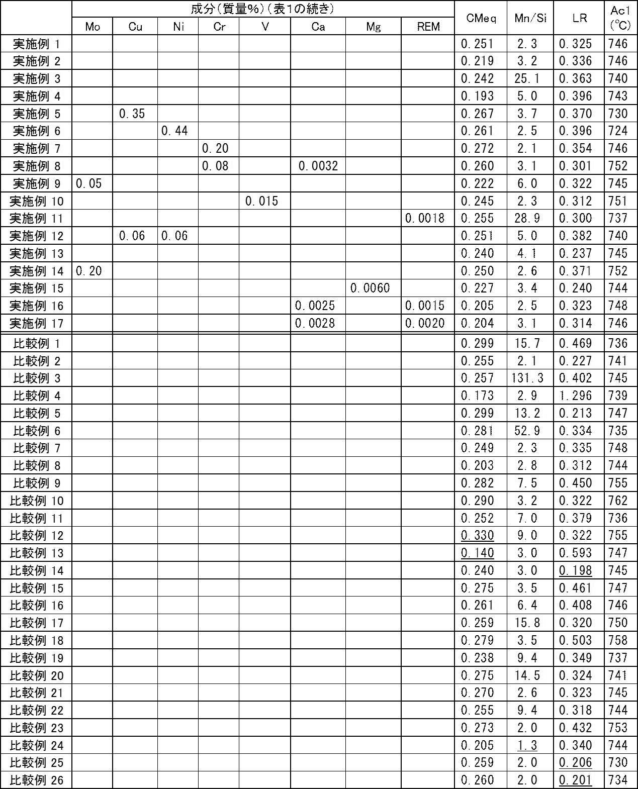

表1~表3に示すように、各実施例の電縫鋼管は、本開示における、TS、YS、YR、vE(母材部)、及びvE(溶接部)を満足した。即ち、各実施例の電縫鋼管は、ある程度の引張強度及び降伏強度を有し、降伏比が低減され、母材部及び溶接部の靭性に優れることが示された。
As shown in Tables 1 to 3, the ERW steel pipe of each example satisfied TS, YS, YR, vE (base material part), and vE (welded part) in the present disclosure. That is, it was shown that the ERW steel pipe of each example has a certain degree of tensile strength and yield strength, the yield ratio is reduced, and the toughness of the base metal part and the welded part is excellent.
C量が上限を超過した比較例1では、F分率が低下し、YRが高くなった。
Si量が上限を超過した比較例2では、溶接部の靭性が劣化した。
Si量が下限を下回った比較例3では、母材部及び溶接部の靭性が劣化した。この理由は、脱酸が不十分となり粗大な酸化物が生じたためと考えられる。
Mn量が下限を下回った比較例4では、母材部及び溶接部の靭性が劣化した。この理由は、S起因の脆化が起こったためと考えられる。
Mn量が上限を超過した比較例5では、母材部及び溶接部の靭性が劣化した。この理由は、MnS起因の割れが生じ易くなったためと考えられる。
Tiが下限を下回った比較例6では、母材部及び溶接部の靭性が劣化した。この理由は、結晶粒が粗大になったためと考えられる。
Tiが上限を超過した比較例7では、母材部及び溶接部の靭性が劣化した。この理由は、粗大なTiNが生成したためと考えられる。
Nbが下限を下回った比較例8では、母材部の靭性が劣化した。この理由は、未再結晶圧延が不十分となったためと考えられる。
Nbが上限を超過した比較例9では、母材部及び溶接部の靭性が劣化した。この理由は、粗大なNb炭窒化物が生成したためと考えられる。
Alが下限を下回った比較例10では、母材部及び溶接部の靭性が劣化した。この理由は、この理由は、脱酸が不十分となったためと考えられる。
Alが上限を超過した比較例11では、溶接部の靭性が劣化した。この理由は、Al系介在物が多量に生成されたためと考えられる。
CMeqが上限を超過した比較例12では、YS及びTSが上限を超えた。
CMeqが下限を下回った比較例13では、F分率が上限を超過し、TSが下限を下回った。 In Comparative Example 1 in which the amount of C exceeded the upper limit, the F fraction decreased and YR increased.
In Comparative Example 2 in which the Si amount exceeded the upper limit, the toughness of the welded portion deteriorated.
In Comparative Example 3 in which the Si amount was below the lower limit, the toughness of the base metal part and the welded part deteriorated. This is probably because deoxidation was insufficient and a coarse oxide was generated.
In Comparative Example 4 where the amount of Mn was below the lower limit, the toughness of the base metal part and the welded part deteriorated. The reason is considered to be that embrittlement due to S occurred.
In Comparative Example 5 in which the amount of Mn exceeded the upper limit, the toughness of the base metal part and the welded part deteriorated. The reason for this is considered to be that cracks due to MnS are likely to occur.
In Comparative Example 6 where Ti was below the lower limit, the toughness of the base metal part and the welded part deteriorated. The reason for this is considered that the crystal grains became coarse.
In Comparative Example 7 where Ti exceeded the upper limit, the toughness of the base metal part and the welded part deteriorated. The reason for this is considered to be that coarse TiN was generated.
In Comparative Example 8 where Nb was below the lower limit, the toughness of the base material portion was deteriorated. The reason for this is considered to be that non-recrystallization rolling has become insufficient.
In Comparative Example 9 where Nb exceeded the upper limit, the toughness of the base metal part and the welded part deteriorated. The reason for this is considered to be that coarse Nb carbonitride was produced.
In Comparative Example 10 where Al was below the lower limit, the toughness of the base metal part and the welded part deteriorated. The reason for this is considered that deoxidation is insufficient.
In Comparative Example 11 in which Al exceeded the upper limit, the toughness of the welded portion deteriorated. The reason for this is considered that a large amount of Al-based inclusions were generated.
In Comparative Example 12 where CMeq exceeded the upper limit, YS and TS exceeded the upper limit.
In Comparative Example 13 in which CMeq was below the lower limit, the F fraction exceeded the upper limit, and TS was below the lower limit.
LRが0.210を下回った比較例14では、降伏比が90%を超えた。
比較例15では、YS及びYRが上限を超過した。この理由は、焼戻し温度が低すぎたために、焼戻しによって造管ひずみを緩和させる効果(即ち、焼戻しによって転位密度を低減させる効果)が不十分であり、かつ、転位上析出が不十分であったためと考えられる。
比較例16では、母材部及び溶接部の靭性が低下した(即ち、母材部及び溶接部のvEが、いずれも下限を下回った)。この理由は、焼戻し温度が高すぎたために、一部の領域においてオーステナイトへの変態が起こり、上記一部の領域でCの濃度が高くなり、その結果、その後の冷却により、島状マルテンサイト(MA)が生成されたためと考えられる。
比較例17では、YRが90%を超えた。この理由は、サイザー真円度変化量が小さかったため、転位の導入及び転位上析出が不十分であったためと考えられる。
比較例18では、YRが90%を超えた。この理由は、焼戻し時間が短かったために、転位上析出が不十分であったためと考えられる。
N量が下限を下回った比較例19では、母材部及び溶接部の靭性が劣化した。この理由は、結晶粒が粗大となったためと考えられる。
N量が上限を超えた比較例20では、母材部及び溶接部の靭性が劣化した。この理由は、炭化物が粗大となったためと考えられる。
比較例21~23では、YRが90%を超えた。この理由は、サイザー真円度変化量が小さかったため、転位の導入及び転位上析出が不十分であったためと考えられる。
Mn/Si比が2.0以下である比較例24では、溶接部の靭性が劣化した。
LRが0.210を下回った比較例25及び26では、降伏比が90%を超えた。 In Comparative Example 14 where LR was less than 0.210, the yield ratio exceeded 90%.
In Comparative Example 15, YS and YR exceeded the upper limit. This is because the tempering temperature was too low, so the effect of relaxing pipe forming strain by tempering (that is, the effect of reducing dislocation density by tempering) was insufficient, and precipitation on dislocations was insufficient. it is conceivable that.
In Comparative Example 16, the toughness of the base metal part and the welded part was reduced (that is, the vE of the base metal part and the welded part was below the lower limit). The reason for this is that since the tempering temperature is too high, transformation into austenite occurs in some areas, and the concentration of C increases in the above-mentioned some areas. As a result, the island-like martensite ( This is probably because MA) was generated.
In Comparative Example 17, YR exceeded 90%. The reason for this is thought to be that introduction of dislocations and precipitation on dislocations were insufficient because the change in sizer roundness was small.
In Comparative Example 18, YR exceeded 90%. The reason for this is thought to be that precipitation on dislocations was insufficient because the tempering time was short.
In Comparative Example 19 in which the N amount was below the lower limit, the toughness of the base metal part and the welded part deteriorated. The reason for this is considered to be that the crystal grains became coarse.
In Comparative Example 20 in which the N amount exceeded the upper limit, the toughness of the base metal part and the welded part deteriorated. The reason for this is thought to be that the carbide became coarse.
In Comparative Examples 21 to 23, YR exceeded 90%. The reason for this is thought to be that introduction of dislocations and precipitation on dislocations were insufficient because the change in sizer roundness was small.
In Comparative Example 24 where the Mn / Si ratio was 2.0 or less, the toughness of the welded portion deteriorated.
In Comparative Examples 25 and 26 in which the LR was below 0.210, the yield ratio exceeded 90%.
日本国特許出願2016-056858の開示はその全体が参照により本明細書に取り込まれる。
本明細書に記載された全ての文献、特許出願、および技術規格は、個々の文献、特許出願、および技術規格が参照により取り込まれることが具体的かつ個々に記された場合と同程度に、本明細書中に参照により取り込まれる。 The disclosure of Japanese Patent Application No. 2016-056858 is incorporated herein by reference in its entirety.
All documents, patent applications, and technical standards mentioned in this specification are to the same extent as if each individual document, patent application, and technical standard were specifically and individually described to be incorporated by reference, Incorporated herein by reference.
Claims (5)
- 母材部及び電縫溶接部を含み、
前記母材部の化学組成が、質量%で、
C :0.080~0.120%、
Mn:0.30~1.00%、
Ti:0.005~0.050%、
Nb:0.010~0.100%、
N :0.001~0.020%、
Si:0.010~0.450%、
Al:0.001~0.100%、
P :0~0.030%、
S :0~0.0100%、
Mo:0~0.50%、
Cu:0~1.00%、
Ni:0~1.00%、
Cr:0~1.00%、
V :0~0.100%、
Ca:0~0.0100%、
Mg:0~0.0100%、
REM:0~0.0100%、並びに
残部:Fe及び不純物からなり、
下記式(1)で示されるCMeqが0.170~0.300であり、
Siの質量%に対するMnの質量%の比が2.0以上であり、
下記式(2)で示されるLRが0.210以上であり、
前記母材部の金属組織を走査型電子顕微鏡を用いて1000倍の倍率で観察した場合に、フェライトからなる第一相の面積率が60~98%であり、残部である第二相が焼戻しベイナイトを含み、
管軸方向の降伏強度が390~562MPaであり、
管軸方向の引張強度が520~690MPaであり、
管軸方向の降伏比が90%以下であり、
前記母材部における管周方向のシャルピー吸収エネルギーが、0℃において100J以上であり、
前記電縫溶接部における管周方向のシャルピー吸収エネルギーが、0℃において80J以上である
ラインパイプ用電縫鋼管。
CMeq=C+Mn/6+Cr/5+(Ni+Cu)/15+Nb+Mo/3+V … 式(1)
LR=(2.1×C+Nb)/Mn … 式(2)
〔式(1)及び式(2)において、C、Mn、Cr、Ni、Cu、Nb、Mo、及びVは、それぞれ、各元素の質量%を表す。〕 Including the base metal part and the ERW welded part,
The chemical composition of the base material part is mass%,
C: 0.080 to 0.120%,
Mn: 0.30 to 1.00%
Ti: 0.005 to 0.050%,
Nb: 0.010 to 0.100%,
N: 0.001 to 0.020%,
Si: 0.010 to 0.450%,
Al: 0.001 to 0.100%,
P: 0 to 0.030%,
S: 0 to 0.0100%,
Mo: 0 to 0.50%,
Cu: 0 to 1.00%,
Ni: 0 to 1.00%,
Cr: 0 to 1.00%,
V: 0 to 0.100%,
Ca: 0 to 0.0100%,
Mg: 0 to 0.0100%,
REM: 0 to 0.0100% and the balance: Fe and impurities,
CMeq represented by the following formula (1) is 0.170 to 0.300,
The ratio of mass% of Mn to mass% of Si is 2.0 or more,
LR represented by the following formula (2) is 0.210 or more,
When the metal structure of the base material part is observed at a magnification of 1000 times using a scanning electron microscope, the area ratio of the first phase made of ferrite is 60 to 98%, and the remaining second phase is tempered. Including bainite,
Yield strength in the tube axis direction is 390 to 562 MPa,
The tensile strength in the tube axis direction is 520 to 690 MPa,
The yield ratio in the tube axis direction is 90% or less,
The Charpy absorbed energy in the pipe circumferential direction in the base material part is 100 J or more at 0 ° C.,
An electric resistance welded steel pipe for line pipes, wherein Charpy absorbed energy in the pipe circumferential direction in the electric resistance welded portion is 80 J or more at 0 ° C.
CMeq = C + Mn / 6 + Cr / 5 + (Ni + Cu) / 15 + Nb + Mo / 3 + V Formula (1)
LR = (2.1 × C + Nb) / Mn Formula (2)
[In Formula (1) and Formula (2), C, Mn, Cr, Ni, Cu, Nb, Mo, and V represent the mass% of each element, respectively. ] - 前記母材部の化学組成が、質量%で、
Mo:0%超0.50%以下、
Cu:0%超1.00%以下、
Ni:0%超1.00%以下、
Cr:0%超1.00%以下、
V :0%超0.100%以下、
Ca:0%超0.0100%以下、
Mg:0%超0.0100%以下、及び
REM:0%超0.0100%以下
の1種又は2種以上を含有する請求項1に記載のラインパイプ用電縫鋼管。 The chemical composition of the base material part is mass%,
Mo: more than 0% and 0.50% or less,
Cu: more than 0% and 1.00% or less,
Ni: more than 0% and 1.00% or less,
Cr: more than 0% and 1.00% or less,
V: more than 0% and 0.100% or less,
Ca: more than 0% and 0.0100% or less,
The ERW steel pipe for line pipes according to claim 1, comprising one or more of Mg: more than 0% and 0.0100% or less and REM: more than 0% and 0.0100% or less. - 前記母材部の金属組織を透過型電子顕微鏡を用いて100000倍の倍率で観察した場合に、円相当径100nm以下の析出物の面積率が0.10~1.00%である請求項1又は請求項2に記載のラインパイプ用電縫鋼管。 2. The area ratio of precipitates having a circle-equivalent diameter of 100 nm or less is 0.10 to 1.00% when the metal structure of the base material part is observed at a magnification of 100000 times using a transmission electron microscope. Or the electric-resistance-welded steel pipe for line pipes of Claim 2.
- 前記母材部の化学組成におけるNbの含有量が、質量%で、0.020%以上である請求項1~請求項3のいずれか1項に記載のラインパイプ用電縫鋼管。 The ERW steel pipe for a line pipe according to any one of claims 1 to 3, wherein the Nb content in the chemical composition of the base material part is 0.020% or more by mass%.
- 肉厚が10~25mmであり、外径が114.3~609.6mmである請求項1~請求項4のいずれか1項に記載のラインパイプ用電縫鋼管。 The ERW steel pipe for a line pipe according to any one of claims 1 to 4, wherein the wall thickness is 10 to 25 mm and the outer diameter is 114.3 to 609.6 mm.
Priority Applications (4)
| Application Number | Priority Date | Filing Date | Title |
|---|---|---|---|
| KR1020187015522A KR20180077259A (en) | 2016-03-22 | 2017-03-13 | Steel pipe for line pipe |
| EP17770030.9A EP3375900A4 (en) | 2016-03-22 | 2017-03-13 | Electric resistance welded steel tube for line pipe |
| JP2017535722A JP6213703B1 (en) | 2016-03-22 | 2017-03-13 | ERW steel pipe for line pipe |
| CN201780004490.4A CN108368582A (en) | 2016-03-22 | 2017-03-13 | Spool electric welded steel pipe |
Applications Claiming Priority (2)
| Application Number | Priority Date | Filing Date | Title |
|---|---|---|---|
| JP2016056858 | 2016-03-22 | ||
| JP2016-056858 | 2016-03-22 |
Publications (1)
| Publication Number | Publication Date |
|---|---|
| WO2017163987A1 true WO2017163987A1 (en) | 2017-09-28 |
Family
ID=59899525
Family Applications (1)
| Application Number | Title | Priority Date | Filing Date |
|---|---|---|---|
| PCT/JP2017/010023 WO2017163987A1 (en) | 2016-03-22 | 2017-03-13 | Electric resistance welded steel tube for line pipe |
Country Status (5)
| Country | Link |
|---|---|
| EP (1) | EP3375900A4 (en) |
| JP (1) | JP6213703B1 (en) |
| KR (1) | KR20180077259A (en) |
| CN (1) | CN108368582A (en) |
| WO (1) | WO2017163987A1 (en) |
Cited By (4)
| Publication number | Priority date | Publication date | Assignee | Title |
|---|---|---|---|---|
| JP6693610B1 (en) * | 2019-08-23 | 2020-05-13 | 日本製鉄株式会社 | ERW steel pipe for line pipe |
| WO2020171209A1 (en) * | 2019-02-21 | 2020-08-27 | 日本製鉄株式会社 | High-strength electric-resistance-welded steel pipe, and method for using high-strength electric-resistance-welded steel pipe in construction work to stabilize foundation |
| WO2021200402A1 (en) | 2020-04-02 | 2021-10-07 | Jfeスチール株式会社 | Electroseamed steel pipe, and method for manufacturing same |
| WO2022075027A1 (en) * | 2020-10-05 | 2022-04-14 | Jfeスチール株式会社 | Electric resistance welded steel pipe and method for manufacturing same |
Families Citing this family (5)
| Publication number | Priority date | Publication date | Assignee | Title |
|---|---|---|---|---|
| CN113677816B (en) * | 2019-03-29 | 2022-11-22 | 杰富意钢铁株式会社 | Electric resistance welded steel pipe, method for producing same, and steel pipe pile |
| TR201921217A2 (en) * | 2019-12-24 | 2021-07-26 | Tirsan Kardan Sanayi Ve Ticaret Anonim Sirketi | High strength, low alloy steel composition |
| EP4066954A4 (en) * | 2020-02-10 | 2023-07-05 | Nippon Steel Corporation | Line pipe-use electric resistance welded steel pipe |
| WO2022044271A1 (en) | 2020-08-28 | 2022-03-03 | 日本製鉄株式会社 | Electric resistance welded steel pipe |
| WO2023014330A1 (en) * | 2021-08-04 | 2023-02-09 | Ti̇rsan Kardan Sanayi̇ Ve Ti̇caret Anoni̇m Şi̇rketi̇ | New micro-alloy steel |
Citations (9)
| Publication number | Priority date | Publication date | Assignee | Title |
|---|---|---|---|---|
| JPH10176239A (en) | 1996-10-17 | 1998-06-30 | Kobe Steel Ltd | High strength and low yield ratio hot rolled steel sheet for pipe and its production |
| JP2002302716A (en) * | 2001-04-06 | 2002-10-18 | Sumitomo Metal Ind Ltd | Electric resistance welded tube having excellent strength and toughness and production method therefor |
| JP2007015008A (en) * | 2005-07-11 | 2007-01-25 | Jfe Steel Kk | Method for producing low yr electric resistance welded tube for line pipe |
| JP2010506044A (en) * | 2006-10-06 | 2010-02-25 | エクソンモービル アップストリーム リサーチ カンパニー | Low yield ratio dual phase steel line tube with excellent strain aging resistance |
| JP4466320B2 (en) | 2004-10-27 | 2010-05-26 | Jfeスチール株式会社 | Manufacturing method of low yield ratio ERW steel pipe for line pipe |
| WO2012133558A1 (en) | 2011-03-30 | 2012-10-04 | 新日本製鐵株式会社 | Electroseamed steel pipe and process for producing same |
| WO2013027779A1 (en) * | 2011-08-23 | 2013-02-28 | 新日鐵住金株式会社 | Thick-walled electric-resistance-welded steel pipe and process for producing same |
| JP2014189808A (en) * | 2013-03-26 | 2014-10-06 | Kobe Steel Ltd | Low yield ratio-type high strength steel sheet excellent in hydrogen induced cracking resistance and bendability |
| JP2016056858A (en) | 2014-09-08 | 2016-04-21 | 株式会社テイエルブイ | Steam trap |
Family Cites Families (9)
| Publication number | Priority date | Publication date | Assignee | Title |
|---|---|---|---|---|
| JPH06158177A (en) * | 1992-11-26 | 1994-06-07 | Sumitomo Metal Ind Ltd | Production of high toughness electric resistance welded pipe |
| EP1473376B1 (en) * | 2002-02-07 | 2015-11-18 | JFE Steel Corporation | High strength steel plate and method for production thereof |
| JP4266194B2 (en) * | 2004-09-16 | 2009-05-20 | 株式会社東芝 | Heat resistant steel, heat treatment method for heat resistant steel, and steam turbine rotor for high temperature |
| JP4881773B2 (en) * | 2007-03-23 | 2012-02-22 | 株式会社神戸製鋼所 | Low yield ratio high strength steel plate with excellent low temperature toughness of weld heat affected zone |
| KR101257547B1 (en) * | 2007-07-23 | 2013-04-23 | 신닛테츠스미킨 카부시키카이샤 | Steel pipes excellent in deformation characteristics and process for manufacturing the same |
| WO2011052095A1 (en) * | 2009-10-28 | 2011-05-05 | 新日本製鐵株式会社 | Steel plate for line pipes with excellent strength and ductility and process for production of same |
| CN103014554B (en) * | 2011-09-26 | 2014-12-03 | 宝山钢铁股份有限公司 | Low-yield-ratio high-tenacity steel plate and manufacture method thereof |
| JP5708723B2 (en) * | 2013-07-09 | 2015-04-30 | Jfeスチール株式会社 | Thick ERW steel pipe with excellent low temperature fracture toughness for line pipe and method for producing the same |
| EP3128029B1 (en) * | 2014-03-31 | 2020-05-27 | JFE Steel Corporation | Steel material for highly-deformable line pipes having superior strain aging characteristics and anti-hic characteristics, method for manufacturing same, and welded steel pipe |
-
2017
- 2017-03-13 CN CN201780004490.4A patent/CN108368582A/en active Pending
- 2017-03-13 WO PCT/JP2017/010023 patent/WO2017163987A1/en active Application Filing
- 2017-03-13 JP JP2017535722A patent/JP6213703B1/en not_active Expired - Fee Related
- 2017-03-13 KR KR1020187015522A patent/KR20180077259A/en active IP Right Grant
- 2017-03-13 EP EP17770030.9A patent/EP3375900A4/en not_active Withdrawn
Patent Citations (9)
| Publication number | Priority date | Publication date | Assignee | Title |
|---|---|---|---|---|
| JPH10176239A (en) | 1996-10-17 | 1998-06-30 | Kobe Steel Ltd | High strength and low yield ratio hot rolled steel sheet for pipe and its production |
| JP2002302716A (en) * | 2001-04-06 | 2002-10-18 | Sumitomo Metal Ind Ltd | Electric resistance welded tube having excellent strength and toughness and production method therefor |
| JP4466320B2 (en) | 2004-10-27 | 2010-05-26 | Jfeスチール株式会社 | Manufacturing method of low yield ratio ERW steel pipe for line pipe |
| JP2007015008A (en) * | 2005-07-11 | 2007-01-25 | Jfe Steel Kk | Method for producing low yr electric resistance welded tube for line pipe |
| JP2010506044A (en) * | 2006-10-06 | 2010-02-25 | エクソンモービル アップストリーム リサーチ カンパニー | Low yield ratio dual phase steel line tube with excellent strain aging resistance |
| WO2012133558A1 (en) | 2011-03-30 | 2012-10-04 | 新日本製鐵株式会社 | Electroseamed steel pipe and process for producing same |
| WO2013027779A1 (en) * | 2011-08-23 | 2013-02-28 | 新日鐵住金株式会社 | Thick-walled electric-resistance-welded steel pipe and process for producing same |
| JP2014189808A (en) * | 2013-03-26 | 2014-10-06 | Kobe Steel Ltd | Low yield ratio-type high strength steel sheet excellent in hydrogen induced cracking resistance and bendability |
| JP2016056858A (en) | 2014-09-08 | 2016-04-21 | 株式会社テイエルブイ | Steam trap |
Non-Patent Citations (1)
| Title |
|---|
| See also references of EP3375900A4 * |
Cited By (11)
| Publication number | Priority date | Publication date | Assignee | Title |
|---|---|---|---|---|
| WO2020171209A1 (en) * | 2019-02-21 | 2020-08-27 | 日本製鉄株式会社 | High-strength electric-resistance-welded steel pipe, and method for using high-strength electric-resistance-welded steel pipe in construction work to stabilize foundation |
| JPWO2020171209A1 (en) * | 2019-02-21 | 2021-03-11 | 日本製鉄株式会社 | How to use high-strength electric resistance pipes and high-strength electric resistance pipes for ground stabilization work |
| CN113423846A (en) * | 2019-02-21 | 2021-09-21 | 日本制铁株式会社 | Use method of high-strength electric welding steel pipe and high-strength electric welding steel pipe for foundation stabilization engineering |
| CN113423846B (en) * | 2019-02-21 | 2022-09-20 | 日本制铁株式会社 | Use method of high-strength electric welding steel pipe and high-strength electric welding steel pipe for foundation stabilization engineering |
| JP6693610B1 (en) * | 2019-08-23 | 2020-05-13 | 日本製鉄株式会社 | ERW steel pipe for line pipe |
| WO2021038632A1 (en) | 2019-08-23 | 2021-03-04 | 日本製鉄株式会社 | Electric-resistance-welded steel pipe for line pipes |
| KR20220002484A (en) | 2019-08-23 | 2022-01-06 | 닛폰세이테츠 가부시키가이샤 | Electric resistance welded steel pipe for line pipe |
| WO2021200402A1 (en) | 2020-04-02 | 2021-10-07 | Jfeスチール株式会社 | Electroseamed steel pipe, and method for manufacturing same |
| KR20220145392A (en) | 2020-04-02 | 2022-10-28 | 제이에프이 스틸 가부시키가이샤 | Electric resistance welded pipe and manufacturing method thereof |
| WO2022075027A1 (en) * | 2020-10-05 | 2022-04-14 | Jfeスチール株式会社 | Electric resistance welded steel pipe and method for manufacturing same |
| JP7081727B1 (en) * | 2020-10-05 | 2022-06-07 | Jfeスチール株式会社 | Electric pipe and its manufacturing method |
Also Published As
| Publication number | Publication date |
|---|---|
| JP6213703B1 (en) | 2017-10-18 |
| EP3375900A1 (en) | 2018-09-19 |
| EP3375900A4 (en) | 2019-07-17 |
| JPWO2017163987A1 (en) | 2018-03-29 |
| CN108368582A (en) | 2018-08-03 |
| KR20180077259A (en) | 2018-07-06 |
Similar Documents
| Publication | Publication Date | Title |
|---|---|---|
| JP6213703B1 (en) | ERW steel pipe for line pipe | |
| JP6288390B1 (en) | AZROLL ERW Steel Pipe for Line Pipe | |
| US7879287B2 (en) | Hot-rolled steel sheet for high-strength electric-resistance welded pipe having sour-gas resistance and excellent weld toughness, and method for manufacturing the same | |
| KR101333854B1 (en) | Thick high-tensile-strength hot-rolled steel sheet with excellent low-temperature toughness and process for production of same | |
| JP5293903B1 (en) | Thick ERW Steel Pipe and Method for Manufacturing the Same | |
| JP6260757B1 (en) | AZROLL ERW Steel Pipe and Hot Rolled Steel Sheet for Line Pipe | |
| WO2018008194A1 (en) | Electroseamed steel pipe for line pipe | |
| JP6587041B1 (en) | ERW steel pipe for line pipe | |
| WO2015012317A1 (en) | Steel plate for line pipe, and line pipe | |
| JP6575734B1 (en) | ERW steel pipe for line pipe | |
| JP2015190026A (en) | Thick high strength electroseamed steel pipe for linepipe and manufacturing method therefor | |
| WO2017110254A1 (en) | As-rolled type k55 electric-resistance-welded oil well pipe, and hot-rolled steel plate | |
| WO2018139096A1 (en) | Electric resistance welded steel tube for coiled tubing, and production method therefor | |
| WO2018066249A1 (en) | Electric resistance-welded steel pipe for torsion beam | |
| JP2018178210A (en) | Electroseamed steel pipe for linepipe and manufacturing method therefor | |
| JP6213702B1 (en) | ERW steel pipe for line pipe | |
| JP6693610B1 (en) | ERW steel pipe for line pipe | |
| JP7200588B2 (en) | ERW steel pipe for oil well and manufacturing method thereof | |
| JP7448804B2 (en) | ERW steel pipes for line pipes and hot rolled steel plates for line pipes | |
| WO2019234851A1 (en) | Electric resistance welded steel pipe for oil wells | |
| JP2023171336A (en) | Electroseamed steel pipe and steel sheet to be served as raw material of electroseamed steel pipe |
Legal Events
| Date | Code | Title | Description |
|---|---|---|---|
| ENP | Entry into the national phase |
Ref document number: 2017535722 Country of ref document: JP Kind code of ref document: A |
|
| ENP | Entry into the national phase |
Ref document number: 20187015522 Country of ref document: KR Kind code of ref document: A |
|
| WWE | Wipo information: entry into national phase |
Ref document number: 2017770030 Country of ref document: EP |
|
| NENP | Non-entry into the national phase |
Ref country code: DE |